Watchdog NTC to F500 with Ethernet interface REV3 · 9 137 – 153 274 – 307 10 154 - 170 308 -...
25
F500 Elite. FIELDBUS ADAPTER. Watchdog NTC Elite to Ethernet/Modbus TCP communications. (Software Version 9.5.x)
Transcript of Watchdog NTC to F500 with Ethernet interface REV3 · 9 137 – 153 274 – 307 10 154 - 170 308 -...

F500 Elite.
FIELDBUS ADAPTER.
Watchdog NTC Elite to Ethernet/Modbus TCP
communications. (Software Version 9.5.x)

Watchdog NTC to F500 with Ethernet interface REV3.doc 2
CONTENTS INTRODUCTION 1 SPECIFICATIONS 2 INSTALLATION INSTRUCTIONS 3 ELECTRICAL WIRING 4 OPERATING INSTRUCTIONS
FAULT FINDING
CONTACT INFORMATION
DRAWINGS A CONNECTING THE F500 ELITE TO AN AC SUPPLY B CONNECTING THE F500 ELITE TO A DC SUPPLY C F500 ELITE TO WATCHDOG ELITE CONNECTIONS D F500 ELITE TO VT100 SERIAL TERMINAL CONNECTIONS E GENERAL CONNECTION DETAIL APPENDIX A – SETTING THE MODULE SWITCHES APPENDIX B – CHANGING THE DEFAULT IP ADDRESS
Watchdog NTC to F500 with Ethernet interface REV3.doc 3
F500 FIELDBUS ADAPTER.
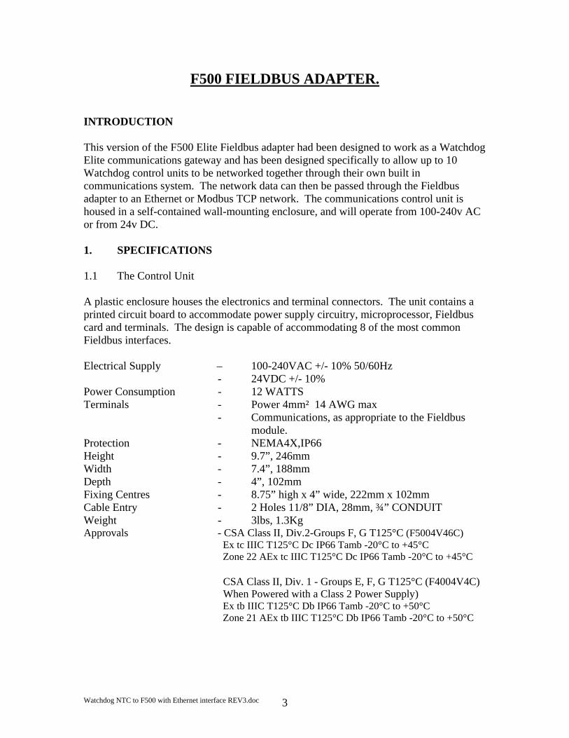
INTRODUCTION This version of the F500 Elite Fieldbus adapter had been designed to work as a Watchdog Elite communications gateway and has been designed specifically to allow up to 10 Watchdog control units to be networked together through their own built in communications system. The network data can then be passed through the Fieldbus adapter to an Ethernet or Modbus TCP network. The communications control unit is housed in a self-contained wall-mounting enclosure, and will operate from 100-240v AC or from 24v DC. 1. SPECIFICATIONS 1.1 The Control Unit A plastic enclosure houses the electronics and terminal connectors. The unit contains a printed circuit board to accommodate power supply circuitry, microprocessor, Fieldbus card and terminals. The design is capable of accommodating 8 of the most common Fieldbus interfaces. Electrical Supply – 100-240VAC +/- 10% 50/60Hz
- 24VDC +/- 10% Power Consumption - 12 WATTS Terminals - Power 4mm² 14 AWG max
- Communications, as appropriate to the Fieldbus module.
Protection - NEMA4X,IP66 Height - 9.7”, 246mm Width - 7.4”, 188mm Depth - 4”, 102mm Fixing Centres - 8.75” high x 4” wide, 222mm x 102mm Cable Entry - 2 Holes 11/8” DIA, 28mm, ¾” CONDUIT Weight - 3lbs, 1.3Kg Approvals - CSA Class II, Div.2-Groups F, G T125°C (F5004V46C)
Ex tc IIIC T125°C Dc IP66 Tamb -20°C to +45°C Zone 22 AEx tc IIIC T125°C Dc IP66 Tamb -20°C to +45°C
CSA Class II, Div. 1 - Groups E, F, G T125°C (F4004V4C) When Powered with a Class 2 Power Supply) Ex tb IIIC T125°C Db IP66 Tamb -20°C to +50°C Zone 21 AEx tb IIIC T125°C Db IP66 Tamb -20°C to +50°C

Watchdog NTC to F500 with Ethernet interface REV3.doc 4
2. INSTALLATION INSTRUCTIONS The Control Unit The Control Unit box should be installed in a suitable control or starter switch room. The box should have sufficient space to open the lid for wiring.
The Control Unit is susceptible to static voltage. Connection of a clean ground to terminal 29 is essential for optimum performance. Prior to this connection, static handling precautions should be taken.
3 ELECRICAL WIRING Refer to Drawings A, B, C & E When installing the equipment in an area which is likely to be hazardous from Ignitable Dusts, use liquid tight conduit and fittings and follow all local codes. 4 OPERATING INSTRUCTIONS The Fieldbus Adapter is a self contained unit and there are no user configurable options with the exception of the Ethernet IP address. The adapter is equipped with three communications ports; RS232, RS485 and Ethernet TCP. The RS232 is a simple interface which can be used for diagnostics purposes. The data from this port is formatted to work with a VT100 display terminal. Any terminal or terminal emulator capable of supporting the VT series or compatible commands can be used with this port although the data has been optimised to work with VT100. The RS232 port operates at a fixed data rate of 9600, N, 8, 1. The RS485 port is a four wire, twin twisted pair full duplex serial port and has been specifically configured to work with the Watchdog communications network. You should not connect any other devices to this port unless you wish to monitor the Watchdog data directly. If this is the case then contact your supplier for details relating to the Watchdog command protocol. The Ethernet port meets the requirements of the 10/100Base-T twisted pair Ethernet physical layer. The Ethernet Fieldbus adapter module is designed for use with the general and the Modbus form of the TCP/IP communications model. The Fieldbus module should be connected through a standard Ethernet communications hub/switch. Alternatively, a peer to peer connection could be made using a single crossover or uplink cable. The Fieldbus Ethernet module will support up to 16 simultaneous Ethernet TCP connections. The default configurations used by the Fieldbus module are as follows. IP Address. 192.168.0. X Port 502

Watchdog NTC to F500 with Ethernet interface REV3.doc 5
This module is currently configured for use as part of an intranet network only therefore further settings are not required. By default, the following settings are also applied. Subnet address 255.255.255.0 Gateway Address 0.0.0.0. These settings can be ignored as they are only useful when connecting to an internet network. The last byte of the IP address “X” refers to the settings made on the switches located on the Ethernet module. The switch block contains 8 switches which represent the last 255 addresses of the IP address 192.168.0.1-255. The right most switch (switch 8) is the Least Significant Bit and the leftmost switch (switch 1) is the Most Significant Bit of the address. The switch is on (selected) when in the down position. If all switches are off (all up) then a fault condition is indicated by led 2 flashing green at the rate of about once every second. The address of the module can be changed at any time without the need to recycle power. Caution must always be exercised when working with an open unit when power is still applied.
The above diagram shows the location of the main parts of the Ethernet Fieldbus module.

Watchdog NTC to F500 with Ethernet interface REV3.doc 6
The Ethernet connections are shown below and are identical to the standard Ethernet RJ45 connections.
The status LED’s are grouped in a single block of four and indicate the following status. Led 1 Status Colour Frequency Description Green Steady on Indicated that the module is connected to an Ethernet network. Led 2 Status Colour Frequency Description Green 1 Hz Indicated that the used IP address is not set by the value of the
DIP switches. Red 1 Hz The Ethernet MAC address is not correct. The module will
not be able to initialise, please contact your supplier. Red 2 Hz This module failed to load Ethernet configuration from the
Flash memory. Red 4 Hz Internal error, please contact your supplier.
Connector Pin
Signal Description.
1 TD+ Positive Transmit Data 2 TD- Negative Transmit data3 RD+ Positive Receive Data 4 No Connection 5 No Connection 6 RD- Negative Receive Data 7 No Connection 8 No Connection Casing PE Protective Earth

Watchdog NTC to F500 with Ethernet interface REV3.doc 7
Led 3 Status Colour Frequency Description Green - Indicates the number of Modbus TCP connections that are
currently established to the module. The LED flashes to indicate the number of connections. For example, if three connections are made then the LED will flash three times, the LED will be off for a period of about two seconds and then the flash cycle will repeat.
Led 4 Status Colour Frequency Description Green - Flashes from green to off when a packet is received or transmitted. The following exception status codes may be generated by the F500. These codes are generated when you are using an incorrect data polling method. Exception Code
Name Description
01 Illegal Function
This module does not support the function code in the query
02 Illegal Data Address
The data address received in the query is outside the initialised memory area in the module.
03 Illegal Data Value
The data in the request is illegal

Watchdog NTC to F500 with Ethernet interface REV3.doc 8
When using the interface as general Ethernet interface, the Modbus references may be ignored. The functionality is identical for both Ethernet and Modbus.
The Watchdog data is automatically read for up to 10 controllers. The data returned is processed and stored in the following format. The position of the data is fixed within the input data table. Although data is returned in a word format, much of the data is in either byte pairs (2 bytes per word) or as two single bytes; more on this later. Word 0 (Byte 1) is used to indicate the number of Watchdogs that are responding to the request for data. Word 0 (Byte 0) is unused. This only occurs once in the entire table. The remaining data stored in the input bytes is constructed as follows.
All the values are stored in Hexadecimal Number of Watchdogs detected this time (Byte 1,0) Once only Watchdog current speed (Byte 3,2) Watchdog current operating status (Byte 5,4) Under speed alarm and stop in % (Byte 7,6) Over speed alarm and stop in % (Byte 9,8) Current calibration value in PPM (Byte 11,10) Display scaling factor (Byte 13,12) NTC Temperature 1 and 2 (Byte 15, 14) NTC Temperature 3 and 4 (Byte 17, 16) NTC Temperature 5 and 6 (Byte 19, 18) NTC temperature sensor status 1 and 2 (Byte 21,20) NTC temperature sensor status 3 and 4 (Byte 23,22) NTC temperature sensor status 5 and 6 (Byte 25,24) Sensor 1 and sensor 2 alarm level (Byte 27,26) Sensor 3 and sensor 4 alarm level (Byte 29,28) Sensor 5 and sensor 6 alarm level (Byte 31,30) Number of sensors in use (Byte 33), Relay status (Byte 32) Persistent alarm value (Byte 35), update counter (Byte 34 The data from each Watchdog is stored in 17 consecutive words (or 34 bytes) of data. The first two bytes of the group of 34 (e.g. 3 & 2) represent the Watchdog speed. The second two bytes of the group of 34 (e.g. 5 & 4) represent the Watchdog status. The Watchdog speed is encoded in the following manner. Four hexadecimal digits are used to represent the measured speed for the Watchdog. The rightmost three and a half are the main body of the speed and the upper half of the fourth is the position of the decimal place within the information. If the most significant two bits are ‘00’ then decoding of the speed is not required. If the two bits are ‘01’, then the
Watchdog Address
Input Words
Input Byte
- 0 0-1 1 1 – 17 2 – 35 2 18 – 34 36 – 69 3 35 – 51 70 -104 4 52 – 68 105 -137 5 69 – 85 138 -171 6 86 – 102 172 - 205 7 103 – 119 206 - 239 8 120 – 136 240 - 273 9 137 – 153 274 – 30710 154 - 170 308 - 341

Watchdog NTC to F500 with Ethernet interface REV3.doc 9
resulting value should be divided by 10 and if the two bits are ‘10’ then the speed should be divided by 100. The top two bits should never be ‘11’ as this has no meaning. Bit 7
Bit 6
Description (e.g. most significant bits of the first speed byte 3)
0 0 Bits 5-0 of the first byte and the whole second represent the speed. 0 1 Same as above but the speed and should be divided by 10 1 0 Same as above but the speed and should be divided by 100 1 1 Not used.
An example of this can be seen below. Watchdog speed = 6E (e.g. byte 3) & 1E (e.g. byte 2). The leftmost digit (6) = ‘0110’ in binary which can be separated into ‘01’ (bits 7 and 6) for speed scaling and ‘10’ (bits 5 and 4) for the upper speed digit. If you strip off bits 7 and 6 you are left with a decoded value of 2E & 1E for the speed and ‘01’ or divide by 10 for the scaling. The speed 2E1E converted to decimal = 11806 and then divided by 10 results in an actual speed of 1180.6. By default the Watchdog will display speed in pulses per minute but it can be scaled to display any value required, refer to the Watchdog manual for further detail. The Watchdog status is encoded as described in the following manner. Two data bytes are used to represent the status for the Watchdog. The first status byte (e.g. byte 5) is the status code and the second byte (e.g. byte 4) represents any data which is associated with the status code. All data is in hexadecimal. Status Code
(Byte 5) Status Data
(Byte 4) What it means. 09 % Complete Watchdog is calibrating (% complete). 0F - Elevator is stopped due to persistent belt slip. 10 - Elevator is stopped due to persistent over calibration. 11 - Misalignment detected on Top & Bottom sensors. 22 - Elevator is stopped and is ready to run (Normal stop
condition) 23 Start-up Delay
In seconds Elevator is accelerating. (xx seconds remain)
24 Speed % Elevator running within programmed limits. 25 Speed % Stop relay has been de-energised (Fault stop
condition) 27 Time to alarm
In seconds Misalignment detected. (xx seconds to alarm)
2A Time to alarm In seconds
Over speeding: Alarm relay about to de-energise (xx seconds to alarm)
2D - Misalignment detected at the top of the elevator. 2F Time to stop
In seconds Over speeding: Stop relay about to de-energise (xx seconds to stop)
31 - Speed display is over range: check the scaling factor. 32 - Start elevator to commence calibration procedure. 36 1-4 Watchdog has detected an internal fault. 39 Time to alarm
In seconds Belt slipping. (xx seconds to alarm)
Watchdog NTC to F500 with Ethernet interface REV3.doc 10
3A Time to stop In seconds
Belt slipping: Stop relay about to de-energise. (xx seconds to stop)
3B - Elevator stopped due to lack of acceleration. 3C Time to stop
In seconds Persistent alarm. (xx seconds to alarm)
3D - Elevator stopped: Speed has exceeded over speed limit.
3E - Interlock signal off, waiting for zero speed. 3F - Elevator stopped: Persistent alarm condition. 40 - Elevator stopped: Severe under speed. 41 - Watchdog is not calibrated: Please see the manual. 42 - Misalignment detected at the bottom of the elevator. 44 - Wrong access code used when changing setup. 46 Speed % Elevator speed less than alarm level (slipping) 47 Speed % Elevator speed more than alarm level ( Over speeding) 49 - Suspected open circuit or faulty PTC bearing
temperature sensor. 4A - Suspected fault on one or more MAS. Could be mains
pickup. 4E - Plug switch is open. 50 - PTC Hot bearing at zone 1. 51 - PTC Hot bearing at zone 2. 52 - PTC Hot bearing at zone 3. 53 - PTC Hot bearing at zone 4. 54 - PTC Hot bearing at zone 5. 55 - PTC Hot bearing at zone 6. 56 - HBS is open circuit at zone 1 57 - HBS is open circuit at zone 2 58 - HBS is open circuit at zone 3 59 - HBS is open circuit at zone 4 5A - HBS is open circuit at zone 5 5B - HBS is open circuit at zone 6
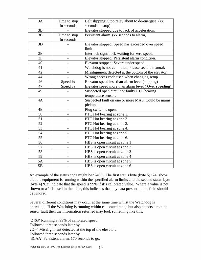
An example of the status code might be ‘2463’. The first status byte (byte 5) ‘24’ show that the equipment is running within the specified alarm limits and the second status byte (byte 4) ‘63’ indicate that the speed is 99% if it’s calibrated value. Where a value is not shown or a ‘-‘is used in the table, this indicates that any data present in this field should be ignored. Several different conditions may occur at the same time whilst the Watchdog is operating. If the Watchdog is running within calibrated range but also detects a motion sensor fault then the information returned may look something like this. ‘2463’ Running at 99% of calibrated speed. Followed three seconds later by 2D--’ Misalignment detected at the top of the elevator. Followed three seconds later by ‘3CAA’ Persistent alarm, 170 seconds to go.

Watchdog NTC to F500 with Ethernet interface REV3.doc 11
The messages would then repeat with any new values in the status data field. Due to some limitations in the speeds involved in updating the Watchdog information, rapid changed of data could be missed or be present for only a very short period of time. If the Watchdog is placed in one of the two test modes, the messages below will be returned in the following order. Bytes 3 and 2
Bytes 5 and 4
The first two bytes show the speed data and the second two bytes show the status and status data.
xx & xx 06 & xx Over speed Stop as a percentage of calibrated speed. xx & xx 05 & xx Over speed Alarm as a percentage of calibrated speed. xx & xx 02 & xx The actual calibrated speed xx & xx 03 & xx Under speed Alarm as a percentage of calibrated speed. xx & xx 04 & xx Under speed Stop as a percentage of calibrated speed.
----- 07 & -- Performing internal test. ---- 4C & -- Testing the Alarm relay. ---- 4D & -- Testing the Stop relay.
Codes 4C and 4D are only returned if the extended test is in operation. Under speed alarm and stop in % (Byte 7, 6) These two bytes show (in % of calibrated speed) the under speed alarm and stop levels. These represent the point at which the Watchdog will generate an alarm or stop condition. Example, if byte 7 is ‘0A’ and byte 6 is ‘14’ then this means that the Watchdog will generate an under speed alarm at 10% (0A) below calibrated speed and will generate a stop condition at 20% (14) below the calibrated speed. Over speed alarm and stop in % (Byte 9, 8) These two bytes show (in % of calibrated speed) the over speed alarm and stop levels. These represent the point at which the Watchdog will generate an alarm or stop condition. Example, if byte 7 is ‘0A’ and byte 6 is ‘14’ then this means that the Watchdog will generate an over speed alarm at 10% (0A) above calibrated speed and will generate a stop condition at 20% (14) above the calibrated speed. Current calibration value in PPM (Byte 11, 10) These two bytes represent the current calibration speed value in Pulses Per Minute (Default). The representation can be changed to other scaled values by using the display scaling value below. Refer to the Watchdog manual for further details about display scaling. Display scaling factor (Byte 13, 12) These two bytes contain a value which is used by the Watchdog to scale the information on the display into a format which represents more accurately what the elevator is doing. The default scaling factor (04B0) results in the display showing the current speed in PPM. Refer to the Watchdog manual for further details about display scaling.
Watchdog NTC to F500 with Ethernet interface REV3.doc 12
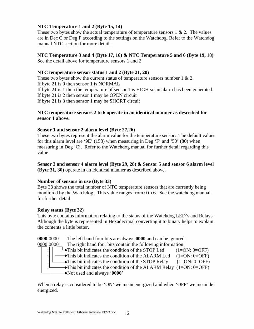
NTC Temperature 1 and 2 (Byte 15, 14) These two bytes show the actual temperature of temperature sensors 1 & 2. The values are in Dec C or Deg F according to the settings on the Watchdog. Refer to the Watchdog manual NTC section for more detail. NTC Temperature 3 and 4 (Byte 17, 16) & NTC Temperature 5 and 6 (Byte 19, 18) See the detail above for temperature sensors 1 and 2 NTC temperature sensor status 1 and 2 (Byte 21, 20) These two bytes show the current status of temperature sensors number 1 & 2. If byte 21 is 0 then sensor 1 is NORMAL If byte 21 is 1 then the temperature of sensor 1 is HIGH so an alarm has been generated. If byte 21 is 2 then sensor 1 may be OPEN circuit If byte 21 is 3 then sensor 1 may be SHORT circuit NTC temperature sensors 2 to 6 operate in an identical manner as described for sensor 1 above. Sensor 1 and sensor 2 alarm level (Byte 27,26) These two bytes represent the alarm value for the temperature sensor. The default values for this alarm level are ‘9E’ (158) when measuring in Deg ‘F’ and ‘50’ (80) when measuring in Deg ‘C’. Refer to the Watchdog manual for further detail regarding this value. Sensor 3 and sensor 4 alarm level (Byte 29, 28) & Sensor 5 and sensor 6 alarm level (Byte 31, 30) operate in an identical manner as described above. Number of sensors in use (Byte 33) Byte 33 shows the total number of NTC temperature sensors that are currently being monitored by the Watchdog. This value ranges from 0 to 6. See the watchdog manual for further detail. Relay status (Byte 32) This byte contains information relating to the status of the Watchdog LED’s and Relays. Although the byte is represented in Hexadecimal converting it to binary helps to explain the contents a little better. 0000:0000 The left hand four bits are always 0000 and can be ignored. 0000:0000 The right hand four bits contain the following information. : This bit indicates the condition of the STOP Led (1=ON: 0=OFF) : This bit indicates the condition of the ALARM Led (1=ON: 0=OFF) : This bit indicates the condition of the STOP Relay (1=ON: 0=OFF)
: This bit indicates the condition of the ALARM Relay (1=ON: 0=OFF)
Not used and always ‘0000’ When a relay is considered to be ‘ON’ we mean energized and when ‘OFF’ we mean de-energized.

Watchdog NTC to F500 with Ethernet interface REV3.doc 13
0000:0000 = 00 then no conditions exist 0000:0010 = 02 then the alarm Led is on 0000:1010 = 0A then the alarm Led and Alarm Relay are active 0000:0011 = 03 then both Led’s are ‘on’ and both Relays are ‘off’ (de-energized) Persistent alarm value NTC only (Byte 35) This is how long the temperature alarm will take in seconds before stopping the elevator. The default value is ‘B4’ 180 seconds. If this value reaches ‘0’ then the elevator will be stopped. Update counter (Byte 34) Every time the F500 successfully receives information from the chosen watchdog, then this counter value will be incremented by 1. The watchdog treats serial communications as low priority so occasionally requests for data can be ignored. It is advisable to keep checking this value so as to know when new data has arrived in the F500. The counter will increment from 0 to 255 and then return to 0 again in a continuous loop. Below is an example of the data returned when the F500 is polling Watchdogs.
Words 1 to 17 (pink) represent Watchdog 1. These are currently all 0 because watchdog 1 isn’t present at this time. Words 18 to 34 (green) represent Watchdog 2. Word 18 which is 0484 HEX tells us that the Watchdog is currently running at 1156 pulses per minutes. Word 19 which is 2465 HEX tells us that the Watchdog is ‘running (24) at 101% (65) of the calibrated speed. The remainder of the information in the example can be decoded using the information as previously described. Words 35 to 51 (blue) represent Watchdog 3. Word 35 which is 0000 HEX tells us that the Watchdog is currently NOT running. Word 36 which is 4100 HEX tells us that the Watchdog is in fact NOT calibrated (41), see the Watchdog manual for more detail about calibration.
Watchdog NTC to F500 with Ethernet interface REV3.doc 14
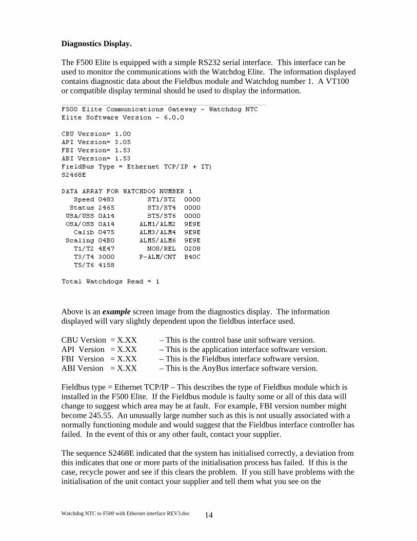
Diagnostics Display. The F500 Elite is equipped with a simple RS232 serial interface. This interface can be used to monitor the communications with the Watchdog Elite. The information displayed contains diagnostic data about the Fieldbus module and Watchdog number 1. A VT100 or compatible display terminal should be used to display the information.
Above is an example screen image from the diagnostics display. The information displayed will vary slightly dependent upon the fieldbus interface used. CBU Version = X.XX – This is the control base unit software version. API Version = X.XX – This is the application interface software version. FBI Version = X.XX – This is the Fieldbus interface software version. ABI Version = X.XX – This is the AnyBus interface software version. Fieldbus type = Ethernet TCP/IP – This describes the type of Fieldbus module which is installed in the F500 Elite. If the Fieldbus module is faulty some or all of this data will change to suggest which area may be at fault. For example, FBI version number might become 245.55. An unusually large number such as this is not usually associated with a normally functioning module and would suggest that the Fieldbus interface controller has failed. In the event of this or any other fault, contact your supplier. The sequence S2468E indicated that the system has initialised correctly, a deviation from this indicates that one or more parts of the initialisation process has failed. If this is the case, recycle power and see if this clears the problem. If you still have problems with the initialisation of the unit contact your supplier and tell them what you see on the

Watchdog NTC to F500 with Ethernet interface REV3.doc 15
diagnostics display. The main area of the display shows the complete data from Watchdog address number 1 as described on pages 8 to 13 of this manual. Diagnostics LED. Located on the main circuit board, just above the RS485 connections to the Watchdog you will find an LED indicator (usually RED). This indicator will flash every time the F500 attempts to communicate with the Watchdogs. The LED will normally flash at a consistent rate followed by a very short pause. The short pause indicates that the F500 is updating the information which it stores internally. A significant deviation from this sequence is an indication that there is a problem. If this happens, contact your supplier for further information.

Watchdog NTC to F500 with Ethernet interface REV3.doc 16
CHECK LIST
For problems after initial start-up 1. Is there excessive interference on the electrical power supply? Power
conditioners and surge (spike) suppressor may have to be fitted. 2. Has the wiring for the Watchdog and Fieldbus been routed away from power
cables? 3. Is the F500 Elite circuit properly grounded? 4. Is the Micro-processor control unit overheating, if so mount in temperature-
controlled environment of maximum temperature 104°F (40°C). 5. Check that high powered ‘Walkie Talkie’ radios are not operated immediately
near the control unit or Watchdogs as this will affect the performance. 6. Check that the communications/power cable is connected correctly and in
accordance with DRG A,B,C and E. 7. Check that there is no exception status reported. 8. If only part of the diagnostics data is displayed on the terminal screen then turn
the F500 Elite off then back on again without removing power to the display terminal.
9. If the Watchdogs are not responding or are intermittent, check that the termination
resistors are correctly fitted.

Watchdog NTC to F500 with Ethernet interface REV3.doc 17
CONTACT INFORMATION
WWW.GO4B.COM

Watchdog NTC to F500 with Ethernet interface REV3.doc 18
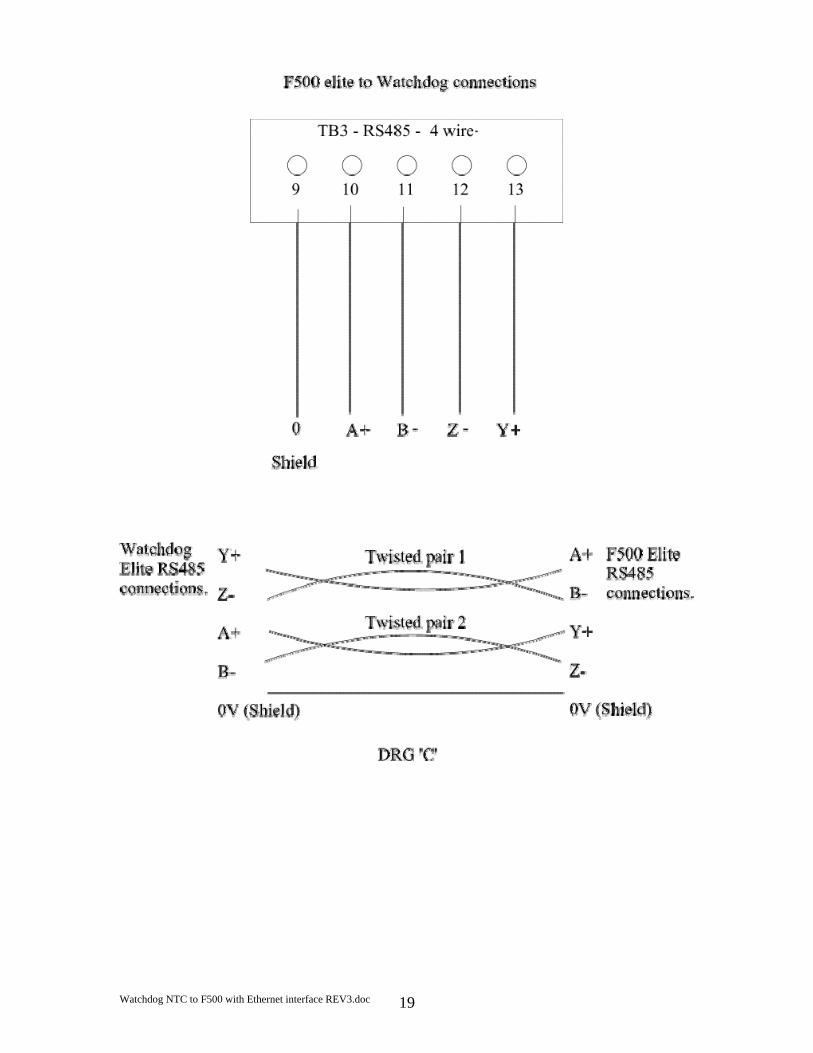
Watchdog NTC to F500 with Ethernet interface REV3.doc 19

Watchdog NTC to F500 with Ethernet interface REV3.doc 20
On more recent versions of the F500 TB1 may be a standard 9 pin Dee connector. This Dee connector is
designed to work with a standard 9 pin to 9 pin serial lead for monitoring the F500

Watchdog NTC to F500 with Ethernet interface REV3.doc 21
Connect 120 OHM ½ watt resistors between A+ and B- and between Y+ and Z- at both the F500 elite end and at the Watchdog which is furthest away from the F500 elite.
PC or Other
Ethernet Device
Maximum of 10 Watchdogs

Watchdog NTC to F500 with Ethernet interface REV3.doc 22
Appendix ‘A’
The table below represents the settings for the Ethernet address switch as described on page 5. The F500 is supplied with a default IP address of 192.168.0.100. The last three numbers of the address can be changed to eliminate conflicts with existing IP address’s already in use on your Ethernet system. The switches are numbered 1 to 8 left to right and switch 8 represents the lowest binary number. In the table below a ‘0’ represents the switch in the OFF or UP position and a ‘1’ represents the switch in the DOWN or ON position. The table is made up in the following format ABC 12345678 Where ABC is the last part of the IP address 192.168.0.ABC and 12345678 represents the switch number from left to right. 001 00000001 033 00100001 065 01000001 097 01100001002 00000010 034 00100010 066 01000010 098 01100010003 00000011 035 00100011 067 01000011 099 01100011004 00000100 036 00100100 068 01000100 100 01100100005 00000101 037 00100101 069 01000101 101 01100101006 00000110 038 00100110 070 01000110 102 01100110007 00000111 039 00100111 071 01000111 103 01100111008 00001000 040 00101000 072 01001000 104 01101000009 00001001 041 00101001 073 01001001 105 01101001010 00001010 042 00101010 074 01001010 106 01101010011 00001011 043 00101011 075 01001011 107 01101011012 00001100 044 00101100 076 01001100 108 01101100013 00001101 045 00101101 077 01001101 109 01101101014 00001110 046 00101110 078 01001110 110 01101110015 00001111 047 00101111 079 01001111 111 01101111016 00010000 048 00110000 080 01010000 112 01110000017 00010001 049 00110001 081 01010001 113 01110001018 00010010 050 00110010 082 01010010 114 01110010019 00010011 051 00110011 083 01010011 115 01110011020 00010100 052 00110100 084 01010100 116 01110100021 00010101 053 00110101 085 01010101 117 01110101022 00010110 054 00110110 086 01010110 118 01110110023 00010111 055 00110111 087 01010111 119 01110111024 00011000 056 00111000 088 01011000 120 01111000025 00011001 057 00111001 089 01011001 121 01111001026 00011010 058 00111010 090 01011010 122 01111010027 00011011 059 00111011 091 01011011 123 01111011028 00011100 060 00111100 092 01011100 124 01111100029 00011101 061 00111101 093 01011101 125 01111101030 00011110 062 00111110 094 01011110 126 01111110031 00011111 063 00111111 095 01011111 127 01111111032 00100000 064 01000000 096 01100000 128 10000000

Watchdog NTC to F500 with Ethernet interface REV3.doc 23
129 10000001 161 10100001 193 11000001 225 11100001130 10000010 162 10100010 194 11000010 226 11100010131 10000011 163 10100011 195 11000011 227 11100011132 10000100 164 10100100 196 11000100 228 11100100133 10000101 165 10100101 197 11000101 229 11100101134 10000110 166 10100110 198 11000110 230 11100110135 10000111 167 10100111 199 11000111 231 11100111136 10001000 168 10101000 200 11001000 232 11101000137 10001001 169 10101001 201 11001001 233 11101001138 10001010 170 10101010 202 11001010 234 11101010139 10001011 171 10101011 203 11001011 235 11101011140 10001100 172 10101100 204 11001100 236 11101100141 10001101 173 10101101 205 11001101 237 11101101142 10001110 174 10101110 206 11001110 238 11101110143 10001111 175 10101111 207 11001111 239 11101111144 10010000 176 10110000 208 11010000 240 11110000145 10010001 177 10110001 209 11010001 241 11110001146 10010010 178 10110010 210 11010010 242 11110010147 10010011 179 10110011 211 11010011 243 11110011148 10010100 180 10110100 212 11010100 244 11110100149 10010101 181 10110101 213 11010101 245 11110101150 10010110 182 10110110 214 11010110 246 11110110151 10010111 183 10110111 215 11010111 247 11110111152 10011000 184 10111000 216 11011000 248 11111000153 10011001 185 10111001 217 11011001 249 11111001154 10011010 186 10111010 218 11011010 250 11111010155 10011011 187 10111011 219 11011011 251 11111011156 10011100 188 10111100 220 11011100 252 11111100157 10011101 189 10111101 221 11011101 253 11111101158 10011110 190 10111110 222 11011110 254 11111110159 10011111 191 10111111 223 11011111 255 11111111160 10100000 192 11000000 224 11100000
The entry in the table above which has a grey background represents the default switch settings.
Watchdog NTC to F500 with Ethernet interface REV3.doc 24
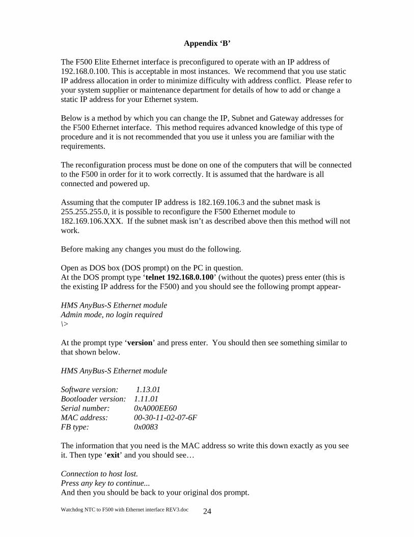
Appendix ‘B’
The F500 Elite Ethernet interface is preconfigured to operate with an IP address of 192.168.0.100. This is acceptable in most instances. We recommend that you use static IP address allocation in order to minimize difficulty with address conflict. Please refer to your system supplier or maintenance department for details of how to add or change a static IP address for your Ethernet system. Below is a method by which you can change the IP, Subnet and Gateway addresses for the F500 Ethernet interface. This method requires advanced knowledge of this type of procedure and it is not recommended that you use it unless you are familiar with the requirements. The reconfiguration process must be done on one of the computers that will be connected to the F500 in order for it to work correctly. It is assumed that the hardware is all connected and powered up. Assuming that the computer IP address is 182.169.106.3 and the subnet mask is 255.255.255.0, it is possible to reconfigure the F500 Ethernet module to 182.169.106.XXX. If the subnet mask isn’t as described above then this method will not work. Before making any changes you must do the following. Open as DOS box (DOS prompt) on the PC in question. At the DOS prompt type ‘telnet 192.168.0.100’ (without the quotes) press enter (this is the existing IP address for the F500) and you should see the following prompt appear- HMS AnyBus-S Ethernet module Admin mode, no login required \> At the prompt type ‘version’ and press enter. You should then see something similar to that shown below. HMS AnyBus-S Ethernet module Software version: 1.13.01 Bootloader version: 1.11.01 Serial number: 0xA000EE60 MAC address: 00-30-11-02-07-6F FB type: 0x0083 The information that you need is the MAC address so write this down exactly as you see it. Then type ‘exit’ and you should see… Connection to host lost. Press any key to continue... And then you should be back to your original dos prompt.

Watchdog NTC to F500 with Ethernet interface REV3.doc 25
Set all of the F500 switches to the UP position (off). Now type the following, the [] characters is used to represent a space just to make it clearer. Arp[]–s[]182.169.106.XXX[] followed by the MAC address that you wrote down earlier. For example, you could type:- Arp[]–s[]182.169.106.100[]00-30-11-02-07-6F then press the enter key. The last part of the IP address (100) is a randomly chosen number that doesn’t conflict with any other IP address on the system. The actual address you will end up using will be set by the F500 Ethernet module switches. Still at the dos prompt type arp[]-a and press enter. You should see something similar to this. Interface: 182.169.106.30 --- 0x10003 Internet Address Physical Address Type 182.169.106.100 00-30-11-02-07-6f static 182.169.106.3 00-40-2b-25-ed-ac dynamic What you see doesn’t ready matter as long as you see your IP and MAC address as entered. Now type ping 182.169.106.100 and press enter. You should now see:- Pinging 182.169.106.100 with 32 bytes of data: Reply from 182.169.106.100: bytes=32 time=3ms TTL=30 Reply from 182.169.106.100: bytes=32 time=1ms TTL=30 Reply from 182.169.106.100: bytes=32 time=1ms TTL=30 Reply from 182.169.106.100: bytes=32 time<1ms TTL=30 Ping statistics for 182.169.106.100: Packets: Sent = 4, Received = 4, Lost = 0 (0% loss), Approximate round trip times in milliseconds: Minimum = 0ms, Maximum = 3ms, Average = 1ms If you don’t get this or similar as the result then you will have to repeat the cycle again. The process is now complete. If required, you can leave the F500 module switches set to all off and you will be able to use the fixed address that you programmed (182.168.106.100 in the example) or you can set the switches according the table in Appendix ‘A’ of this manual if you want a different ending address.