Wastewater Treatment System Needs Assessment May 2017 · standby) 15 HP blowers. Flow exits the...
79
207 North Stewart Street |Geneseo, IL, 61254 Wastewater Treatment System Needs Assessment May 2017 Prepared by: Donohue & Associates, Inc. 1605 South State Street, Suite 1C |Champaign, IL, 61820 donohue-associates.com Donohue Project No.: 13173
Transcript of Wastewater Treatment System Needs Assessment May 2017 · standby) 15 HP blowers. Flow exits the...
207 North Stewart Street |Geneseo, IL, 61254
Wastewater Treatment System Needs Assessment May 2017
Prepared by:
Donohue & Associates, Inc. 1605 South State Street, Suite 1C |Champaign, IL, 61820 donohue-associates.com
Donohue Project No.: 13173
City of Geneseo May, 2017
Wastewater Needs Assessment Donohue & Associates, Inc. Page ii
TABLE OF CONTENTS
Chapter 1 – Executive Summary ........................................................................................................... 1
1.1 Overview ............................................................................................................................ 1
1.2 Recommended Upgrades .................................................................................................... 1
1.3 Cost Opinions ...................................................................................................................... 1
Chapter 2 – Project Background ........................................................................................................... 3
2.1 Study Objective ................................................................................................................... 3
2.2 Facility Overview ................................................................................................................. 3
2.3 NPDEs Permit ...................................................................................................................... 5
Chapter 3 – Identified Improvements ................................................................................................... 8
3.1 Headworks .......................................................................................................................... 8
3.2 Excess Flow Pump Station ................................................................................................. 13
3.3 Grit Removal ..................................................................................................................... 14
3.4 Raw Influent Pumping ....................................................................................................... 16
3.5 Primary Treatment ............................................................................................................ 16
3.6 Trickling Filters .................................................................................................................. 18
3.7 Aeration ............................................................................................................................ 20
3.8 Final Clarification .............................................................................................................. 23
3.9 Secondary Control Building ............................................................................................... 24
3.10 Digestion ........................................................................................................................... 25
3.11 Dewatering ....................................................................................................................... 27
3.12 Effluent Pumping .............................................................................................................. 27
3.13 Lift Stations ....................................................................................................................... 28
3.14 Change in Regulations ....................................................................................................... 28
3.14.1 Disinfection ....................................................................................................................... 28
3.14.2 Phosphorus Removal......................................................................................................... 29

City of Geneseo May, 2017
Wastewater Needs Assessment Donohue & Associates, Inc. Page iii
LIST OF TABLES Table 2-1 Outfall 001 Limits ..................................................................................................................... 6
Table 2-2 Outfall 004 Limits ..................................................................................................................... 7
Table 2-3 Outfall 005 Limits ..................................................................................................................... 7

City of Geneseo May, 2017
Wastewater Needs Assessment Donohue & Associates, Inc. Page iv
LIST OF FIGURES Figure 2-1 Geneseo WWTP and Excess Flow Lagoon Aerial ...................................................................... 4
Figure 2-2 Geneseo WWTP ...................................................................................................................... 5
Figure 3-1 Headworks Building ............................................................................................................... 8
Figure 3-2 Manual Bypass Bar Screen ...................................................................................................... 9
Figure 3-3 Mechanically Cleaned Bar Screen ............................................................................................ 9
Figure 3-4 Parshall Flume - 12" .............................................................................................................. 10
Figure 3-5 Bar Screening Manual Removal ............................................................................................. 10
Figure 3-6 Proposed Location of New Screenings Washer and Compactor, Aerial View .......................... 11
Figure 3-7 Proposed Location of New Screening washer and Compactor, Outside View ......................... 11
Figure 3-8 Butterfly Valve ...................................................................................................................... 12
Figure 3-9 Concrete Barrier for Flooding Prevention .............................................................................. 13
Figure 3-10 Grit Tank ............................................................................................................................. 14
Figure 3-11 Grit Classifier....................................................................................................................... 15
Figure 3-12 Influent Pumps.................................................................................................................... 16
Figure 3-13 Primary Clarifier .................................................................................................................. 17
Figure 3-14 Primary Clarifier Concrete Spalling ...................................................................................... 18
Figure 3-15 Primary Sludge Pump ......................................................................................................... 18
Figure 3-16 Rock and Plastic Trickling Filters .......................................................................................... 19
Figure 3-17 Filter Feed Pumps ............................................................................................................... 20
Figure 3-18 Aeration Basins ................................................................................................................... 21
Figure 3-19 Three 15-HP Blowers ........................................................................................................... 22
Figure 3-20 Final Clarifier ....................................................................................................................... 23
Figure 3-21 Primary Digester ................................................................................................................. 25
Figure 3-22 Secondary Digester ............................................................................................................. 26
Figure 3-23 Chlorination Basin ............................................................................................................... 29
City of Geneseo May, 2017
Wastewater Needs Assessment Donohue & Associates, Inc. Page v
APPENDICES Appendix A – Flow Schematic Appendix B – Hydraulic Profile Appendix C – NPDES Permit Appendix D – Cost Estimates

City of Geneseo May, 2017
Wastewater Needs Assessment Donohue & Associates, Inc. Page vi
ABBREVIATIONS BOD Biological Oxygen Demand DO Dissolved Oxygen GPD Gallon per Day GPM Gallon per Minute IEPA Illinois Environmental Protection Agency MGD Million Gallons per Day NPDES National Pollutant Discharge Elimination System TSS Total Suspended Solids WWTP Wastewater Treatment Plant
City of Geneseo May, 2017
Wastewater Needs Assessment Donohue & Associates, Inc. Page 1
CHAPTER 1 – EXECUTIVE SUMMARY
OVERVIEW
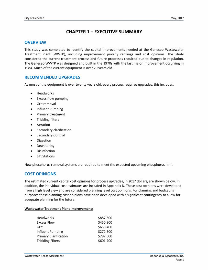
This study was completed to identify the capital improvements needed at the Geneseo Wastewater Treatment Plant (WWTP), including improvement priority rankings and cost opinions. The study considered the current treatment process and future processes required due to changes in regulation. The Geneseo WWTP was designed and built in the 1970s with the last major improvement occurring in 1984. Much of the current equipment is over 20 years old.
RECOMMENDED UPGRADES
As most of the equipment is over twenty years old, every process requires upgrades, this includes:
Headworks
Excess flow pumping
Grit removal
Influent Pumping
Primary treatment
Trickling filters
Aeration
Secondary clarification
Secondary Control
Digestion
Dewatering
Disinfection
Lift Stations
New phosphorus removal systems are required to meet the expected upcoming phosphorus limit.
COST OPINIONS
The estimated current capital cost opinions for process upgrades, in 2017 dollars, are shown below. In addition, the individual cost estimates are included in Appendix D. These cost opinions were developed from a high level view and are considered planning level cost opinions. For planning and budgeting purposes these planning cost opinions have been developed with a significant contingency to allow for adequate planning for the future. Wastewater Treatment Plant Improvements Headworks $887,600 Excess Flow $450,900 Grit $658,400 Influent Pumping $272,500 Primary Clarification $787,600 Trickling Filters $601,700
City of Geneseo May, 2017
Wastewater Needs Assessment Donohue & Associates, Inc. Page 2
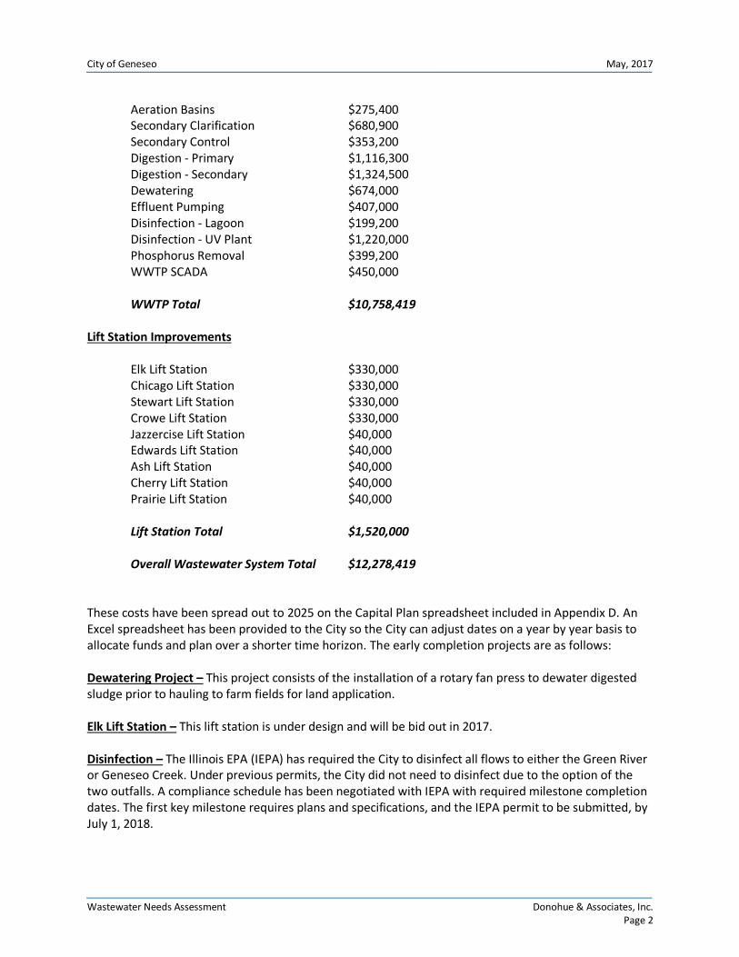
Aeration Basins $275,400 Secondary Clarification $680,900 Secondary Control $353,200 Digestion - Primary $1,116,300 Digestion - Secondary $1,324,500 Dewatering $674,000 Effluent Pumping $407,000 Disinfection - Lagoon $199,200 Disinfection - UV Plant $1,220,000 Phosphorus Removal $399,200 WWTP SCADA $450,000 WWTP Total $10,758,419 Lift Station Improvements Elk Lift Station $330,000 Chicago Lift Station $330,000 Stewart Lift Station $330,000 Crowe Lift Station $330,000 Jazzercise Lift Station $40,000 Edwards Lift Station $40,000 Ash Lift Station $40,000 Cherry Lift Station $40,000 Prairie Lift Station $40,000 Lift Station Total $1,520,000 Overall Wastewater System Total $12,278,419 These costs have been spread out to 2025 on the Capital Plan spreadsheet included in Appendix D. An Excel spreadsheet has been provided to the City so the City can adjust dates on a year by year basis to allocate funds and plan over a shorter time horizon. The early completion projects are as follows: Dewatering Project – This project consists of the installation of a rotary fan press to dewater digested sludge prior to hauling to farm fields for land application. Elk Lift Station – This lift station is under design and will be bid out in 2017. Disinfection – The Illinois EPA (IEPA) has required the City to disinfect all flows to either the Green River or Geneseo Creek. Under previous permits, the City did not need to disinfect due to the option of the two outfalls. A compliance schedule has been negotiated with IEPA with required milestone completion dates. The first key milestone requires plans and specifications, and the IEPA permit to be submitted, by July 1, 2018.
City of Geneseo May, 2017
Wastewater Needs Assessment Donohue & Associates, Inc. Page 3
CHAPTER 2 – PROJECT BACKGROUND
STUDY OBJECTIVE
The objective of this needs assessment is to identify the major capital improvements needed at the Geneseo Wastewater Treatment Plant (WWTP), including improvement priority rankings and high level cost opinions. The report will include current treatment process and future processes required due to changes in regulation.
FACILITY OVERVIEW
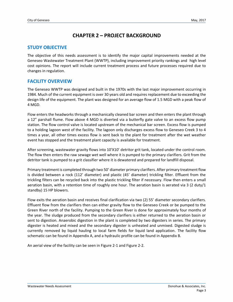
The Geneseo WWTP was designed and built in the 1970s with the last major improvement occurring in 1984. Much of the current equipment is over 30 years old and requires replacement due to exceeding the design life of the equipment. The plant was designed for an average flow of 1.5 MGD with a peak flow of 4 MGD.
Flow enters the headworks through a mechanically cleaned bar screen and then enters the plant through a 12” parshall flume. Flow above 4 MGD is diverted via a butterfly gate valve to an excess flow pump station. The flow control valve is located upstream of the mechanical bar screen. Excess flow is pumped to a holding lagoon west of the facility. The lagoon only discharges excess flow to Geneseo Creek 3 to 4 times a year, all other times excess flow is sent back to the plant for treatment after the wet weather event has stopped and the treatment plant capacity is available for treatment.
After screening, wastewater gravity flows into 10’X10’ detritor grit tank, located under the control room. The flow then enters the raw sewage wet well where it is pumped to the primary clarifiers. Grit from the detritor tank is pumped to a grit classifier where it is dewatered and prepared for landfill disposal.
Primary treatment is completed through two 50’ diameter primary clarifiers. After primary treatment flow is divided between a rock (112’ diameter) and plastic (45’ diameter) trickling filter. Effluent from the trickling filters can be recycled back into the plastic trickling filter if necessary. Flow then enters a small aeration basin, with a retention time of roughly one hour. The aeration basin is aerated via 3 (2 duty/1 standby) 15 HP blowers.
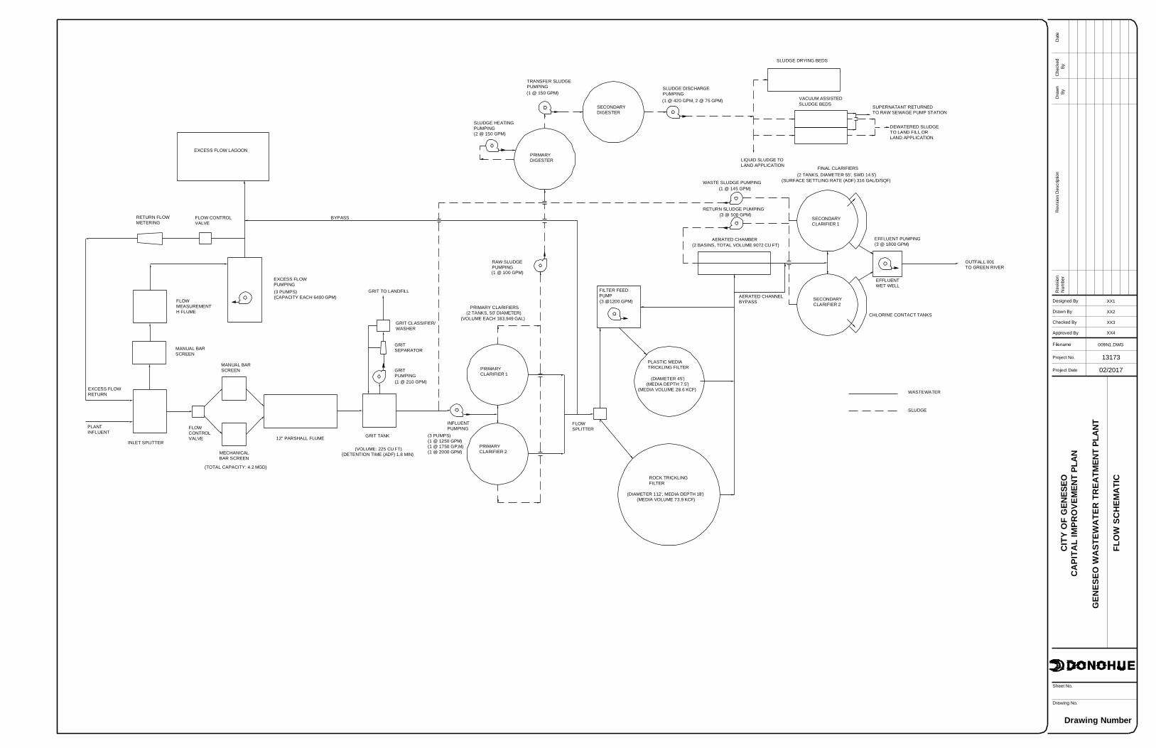
Flow exits the aeration basin and receives final clarification via two (2) 55’ diameter secondary clarifiers. Effluent flow from the clarifiers then can either gravity flow to the Geneseo Creek or be pumped to the Green River north of the facility. Pumping to the Green River is done for approximately four months of the year. The sludge produced from the secondary clarifiers is either returned to the aeration basin or sent to digestion. Anaerobic digestion in the plant is completed by two digesters in series. The primary digester is heated and mixed and the secondary digester is unheated and unmixed. Digested sludge is currently removed by liquid hauling to local farm fields for liquid land application. The facility flow schematic can be found in Appendix A, and a hydraulic profile can be found in Appendix B.
An aerial view of the facility can be seen in Figure 2-1 and Figure 2-2.

City of Geneseo May, 2017
Wastewater Needs Assessment Donohue & Associates, Inc. Page 4
Figure 2-1 Geneseo WWTP and Excess Flow Lagoon Aerial
Excess Flow Lagoon
Geneseo WWTP
City of Geneseo May, 2017
Wastewater Needs Assessment Donohue & Associates, Inc. Page 5
Figure 2-2 Geneseo WWTP
NPDES PERMIT
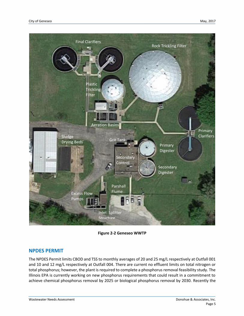
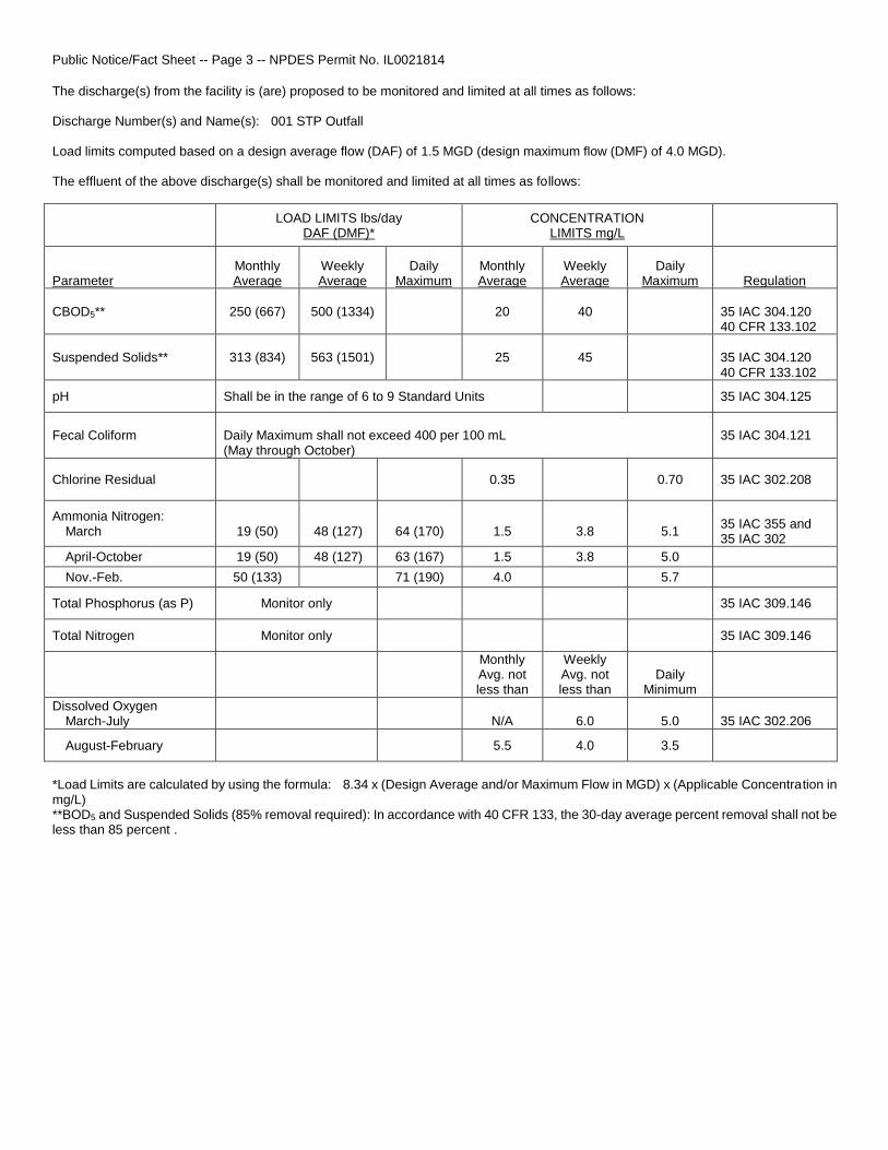
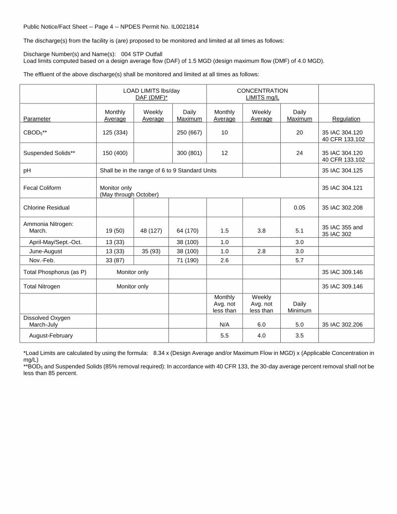
The NPDES Permit limits CBOD and TSS to monthly averages of 20 and 25 mg/L respectively at Outfall 001 and 10 and 12 mg/L respectively at Outfall 004. There are current no effluent limits on total nitrogen or total phosphorus; however, the plant is required to complete a phosphorus removal feasibility study. The Illinois EPA is currently working on new phosphorus requirements that could result in a commitment to achieve chemical phosphorus removal by 2025 or biological phosphorus removal by 2030. Recently the
Final Clarifiers Rock Trickling Filter
Plastic Trickling Filter
Primary Clarifiers
Primary Digester
Secondary Digester
Grit Tank
Aeration Basins
Sludge Drying Beds
Parshall Flume
Inlet Splitter Structure
Excess Flow Pumps
Secondary Control
City of Geneseo May, 2017
Wastewater Needs Assessment Donohue & Associates, Inc. Page 6
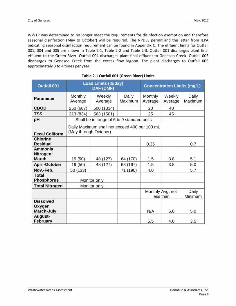
WWTP was determined to no longer meet the requirements for disinfection exemption and therefore seasonal disinfection (May to October) will be required. The NPDES permit and the letter from IEPA indicating seasonal disinfection requirement can be found in Appendix C. The effluent limits for Outfall 001, 004 and 005 are shown in Table 2-1, Table 2-2 and Table 2-3. Outfall 001 discharges plant final effluent to the Green River. Outfall 004 discharges plant final effluent to Geneseo Creek. Outfall 005 discharges to Geneseo Creek from the excess flow lagoon. The plant discharges to Outfall 005 approximately 3 to 4 times per year.
Table 2-1 Outfall 001 (Green River) Limits
Outfall 001 Load Limits (lb/day)
DAF (DMF) Concentration Limits (mg/L)
Parameter Monthly Average
Weekly Average
Daily Maximum
Monthly Average
Weekly Average
Daily Maximum
CBOD 250 (667) 500 (1334) 20 40
TSS 313 (834) 563 (1501) 25 45
pH Shall be in range of 6 to 9 standard units
Fecal Coliform
Daily Maximum shall not exceed 400 per 100 mL (May through October)
Chlorine Residual 0.35 0.7 Ammonia Nitrogen: March 19 (50) 48 (127) 64 (170) 1.5 3.8 5.1
April-October 19 (50) 48 (127) 63 (167) 1.5 3.8 5.0
Nov.-Feb. 50 (133) 71 (190) 4.0 5.7
Total Phosphorus Monitor only
Total Nitrogen Monitor only
Monthly Avg. not
less than Daily
Minimum Dissolved Oxygen March-July N/A 6.0 5.0
August-February 5.5 4.0 3.5

City of Geneseo May, 2017
Wastewater Needs Assessment Donohue & Associates, Inc. Page 7
Table 2-2 Outfall 004 (Geneseo Creek) Limits
Outfall 004 Load Limits (lb/day)
DAF (DMF) Concentration Limits (mg/L)
Parameter Monthly Average
Weekly Average
Daily Maximum
Monthly Average
Weekly Average
Daily Maximum
CBOD 125 (334) 250 (667) 10 20
TSS 150 (400) 300 (801) 12 24
pH Shall be in range of 6 to 9 standard units
Fecal Coliform Monitor Only (May through October)
Chlorine Residual 0.05
Ammonia Nitrogen: March 19 (50) 48 (127) 64 (170) 1.5 3.8 5.1
April-May/Sept.-Oct. 13 (33) 38 (100) 1.0 3.0
June-August 13 (33) 35 (93) 38 (100) 1.0 2.8 3.0
Nov. Feb. 33 (87) 71 (190) 2.6 5.7 Total Phosphorus Monitor only
Total Nitrogen Monitor only
Monthly Avg. not
less than Daily
Minimum Dissolved Oxygen March-July N/A 6.0 5.0 August-February 5.5 4.0 3.5
Table 2-3 Outfall 005 Limits
Outfall 005 Concentration Limits (mg/L)
Parameter Monthly Average Weekly Average
BOD 30 45
TSS 30 45
pH Shall be in range of 6 to 9 standard units
Fecal Coliform Daily Maximum Shall Not Exceed 400 per 100 mL
Chlorine Residual 0.75
Ammonia Nitrogen (as N) Monitor Only
Total Phosphorus (as P) Monitor Only
City of Geneseo May, 2017
Wastewater Needs Assessment Donohue & Associates, Inc. Page 8
CHAPTER 3 – IDENTIFIED IMPROVEMENTS
The Geneseo WWTP was designed and built in the 1970’s. It was last upgraded in 1984. Much of the plant process equipment is over thirty years old. The following sections detail the proposed improvements to the facility.
3.1 HEADWORKS
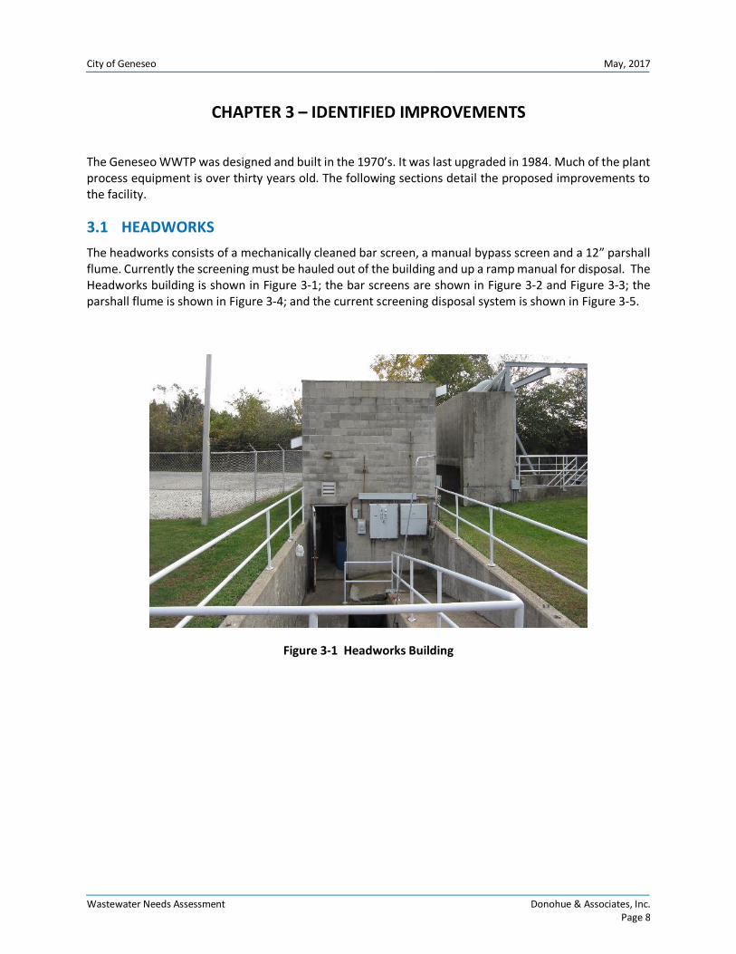
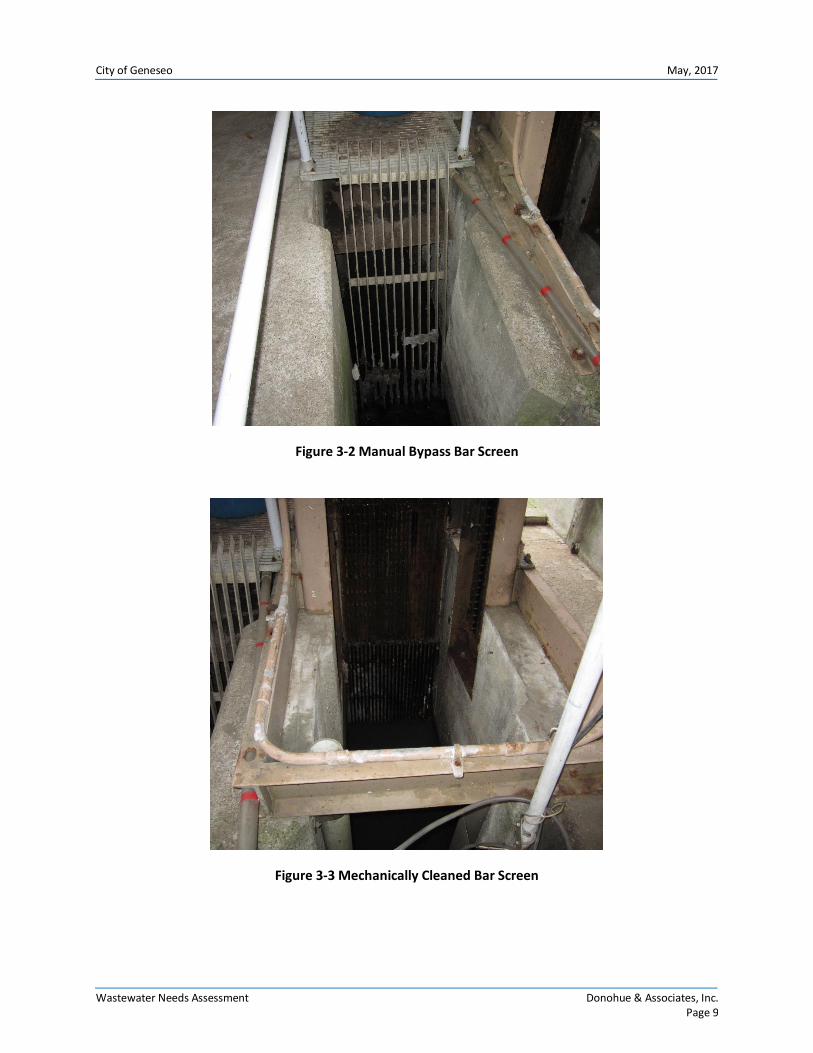
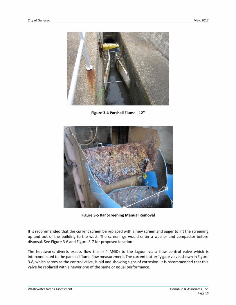
The headworks consists of a mechanically cleaned bar screen, a manual bypass screen and a 12” parshall flume. Currently the screening must be hauled out of the building and up a ramp manual for disposal. The Headworks building is shown in Figure 3-1; the bar screens are shown in Figure 3-2 and Figure 3-3; the parshall flume is shown in Figure 3-4; and the current screening disposal system is shown in Figure 3-5.
Figure 3-1 Headworks Building
City of Geneseo May, 2017
Wastewater Needs Assessment Donohue & Associates, Inc. Page 9
Figure 3-2 Manual Bypass Bar Screen
Figure 3-3 Mechanically Cleaned Bar Screen
City of Geneseo May, 2017
Wastewater Needs Assessment Donohue & Associates, Inc. Page 10
Figure 3-4 Parshall Flume - 12"
Figure 3-5 Bar Screening Manual Removal
It is recommended that the current screen be replaced with a new screen and auger to lift the screening up and out of the building to the west. The screenings would enter a washer and compactor before disposal. See Figure 3-6 and Figure 3-7 for proposed location.
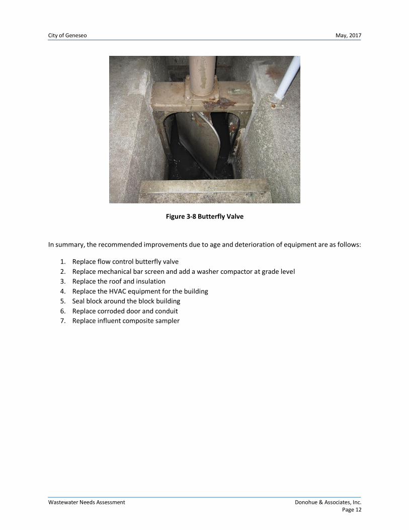
The headworks diverts excess flow (i.e. > 4 MGD) to the lagoon via a flow control valve which is interconnected to the parshall flume flow measurement. The current butterfly gate valve, shown in Figure 3-8, which serves as the control valve, is old and showing signs of corrosion. It is recommended that this valve be replaced with a newer one of the same or equal performance.

City of Geneseo May, 2017
Wastewater Needs Assessment Donohue & Associates, Inc. Page 11
The block around the headworks building needs to be sealed. In addition, the following are also recommended for replacement as they have exceeded their design life: conduit on the outside of the headworks building; roof on the headworks building; the door to the headworks building.
Figure 3-6 Proposed Location of New Screenings Washer and Compactor, Aerial View
Figure 3-7 Proposed Location of New Screening washer and Compactor, Outside View
Proposed location of washer and compactor
City of Geneseo May, 2017
Wastewater Needs Assessment Donohue & Associates, Inc. Page 12
Figure 3-8 Butterfly Valve
In summary, the recommended improvements due to age and deterioration of equipment are as follows:
1. Replace flow control butterfly valve
2. Replace mechanical bar screen and add a washer compactor at grade level
3. Replace the roof and insulation
4. Replace the HVAC equipment for the building
5. Seal block around the block building
6. Replace corroded door and conduit
7. Replace influent composite sampler

City of Geneseo May, 2017
Wastewater Needs Assessment Donohue & Associates, Inc. Page 13
3.2 EXCESS FLOW PUMP STATION
The excess flow pump station consists of three 6400 gpm pumps that can pump a total of 18.4 MGD (2 duty/1 standby). The pumps currently have soft starts that were put in service in 1986. The excess flow is currently pumped 308 feet through a 30” line to manhole #4 where it then flows into 24” line that leads 260 feet into the lagoon. The facility is currently having problems with the manhole over flowing. A concrete surge tower, shown in Figure 3-9, has been built to mitigate the surge. Since the original gravity flow piping was not designed for this pressure condition, there is leakage near the surge tower which is undermining the foundation.
It is recommended that the manhole be removed and either be replaced with an elbow fitting to connect the 30” and 24” pipes or a better designed surge tower to accommodate the short term spike in the hydraulic grade line. It is also recommended to replace the soft starts with VFDs to attenuate the flow surge. A more detailed hydraulic evaluation should be completed to make sure the improvements do not cause a backup to the primary clarifier bypass structure.
Figure 3-9 Concrete Surge Tower
In summary, the recommended improvements due to age and deterioration of equipment are as follows:
1. Replace the current excess flow pumps with new pumps
2. Replace the aged soft starts with new VFD’s for surge attenuation
3. Replace mag meter that controls return flow from the lagoon
4. Hydraulic evaluation and replacement of concrete surge tower to avoid washout and collapse
City of Geneseo May, 2017
Wastewater Needs Assessment Donohue & Associates, Inc. Page 14
3.3 GRIT REMOVAL
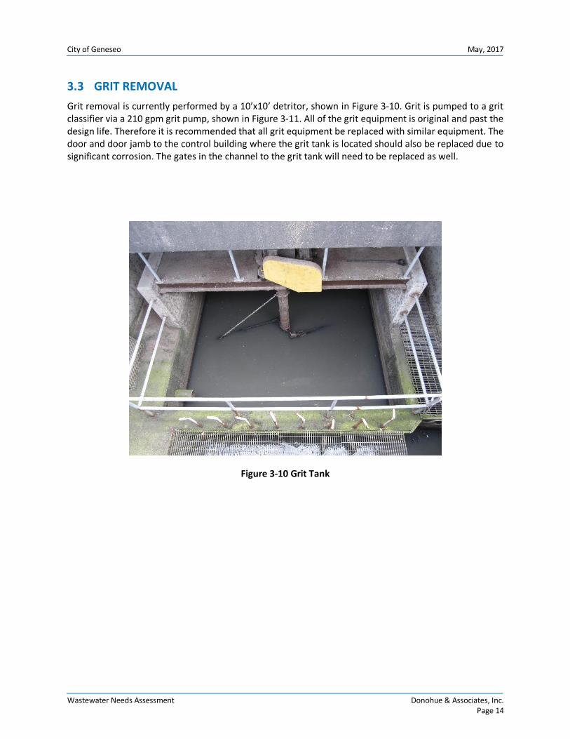
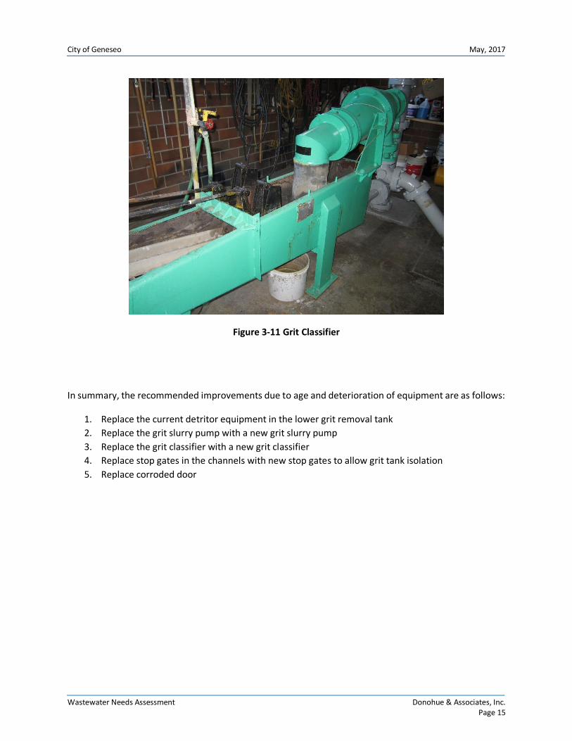
Grit removal is currently performed by a 10’x10’ detritor, shown in Figure 3-10. Grit is pumped to a grit classifier via a 210 gpm grit pump, shown in Figure 3-11. All of the grit equipment is original and past the design life. Therefore it is recommended that all grit equipment be replaced with similar equipment. The door and door jamb to the control building where the grit tank is located should also be replaced due to significant corrosion. The gates in the channel to the grit tank will need to be replaced as well.
Figure 3-10 Grit Tank
City of Geneseo May, 2017
Wastewater Needs Assessment Donohue & Associates, Inc. Page 15
Figure 3-11 Grit Classifier
In summary, the recommended improvements due to age and deterioration of equipment are as follows:
1. Replace the current detritor equipment in the lower grit removal tank
2. Replace the grit slurry pump with a new grit slurry pump
3. Replace the grit classifier with a new grit classifier
4. Replace stop gates in the channels with new stop gates to allow grit tank isolation
5. Replace corroded door
City of Geneseo May, 2017
Wastewater Needs Assessment Donohue & Associates, Inc. Page 16
3.4 RAW INFLUENT PUMPING
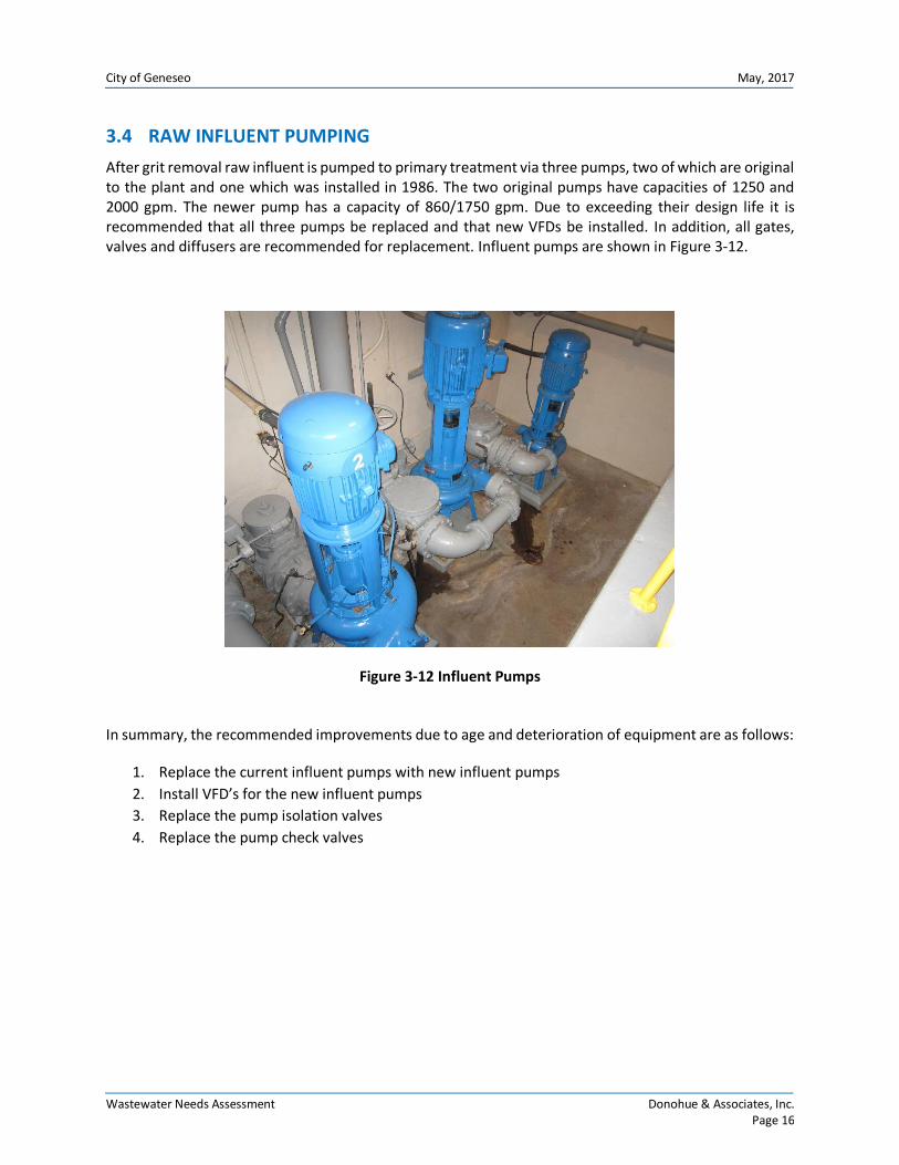
After grit removal raw influent is pumped to primary treatment via three pumps, two of which are original to the plant and one which was installed in 1986. The two original pumps have capacities of 1250 and 2000 gpm. The newer pump has a capacity of 860/1750 gpm. Due to exceeding their design life it is recommended that all three pumps be replaced and that new VFDs be installed. In addition, all gates, valves and diffusers are recommended for replacement. Influent pumps are shown in Figure 3-12.
Figure 3-12 Influent Pumps
In summary, the recommended improvements due to age and deterioration of equipment are as follows:
1. Replace the current influent pumps with new influent pumps
2. Install VFD’s for the new influent pumps
3. Replace the pump isolation valves
4. Replace the pump check valves
City of Geneseo May, 2017
Wastewater Needs Assessment Donohue & Associates, Inc. Page 17
3.5 PRIMARY TREATMENT
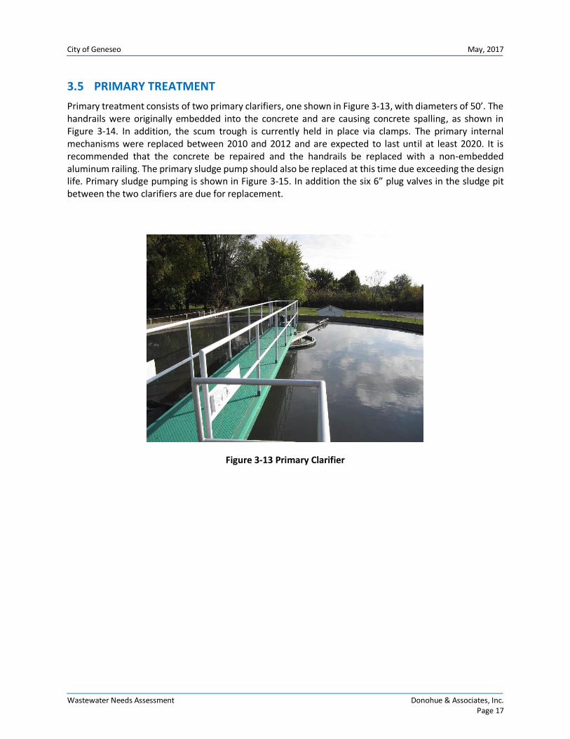
Primary treatment consists of two primary clarifiers, one shown in Figure 3-13, with diameters of 50’. The handrails were originally embedded into the concrete and are causing concrete spalling, as shown in Figure 3-14. In addition, the scum trough is currently held in place via clamps. The primary internal mechanisms were replaced between 2010 and 2012 and are expected to last until at least 2020. It is recommended that the concrete be repaired and the handrails be replaced with a non-embedded aluminum railing. The primary sludge pump should also be replaced at this time due exceeding the design life. Primary sludge pumping is shown in Figure 3-15. In addition the six 6” plug valves in the sludge pit between the two clarifiers are due for replacement.
Figure 3-13 Primary Clarifier

City of Geneseo May, 2017
Wastewater Needs Assessment Donohue & Associates, Inc. Page 18
Figure 3-14 Primary Clarifier Concrete Spalling
Figure 3-15 Primary Sludge Pump
In summary, the recommended improvements due to age and deterioration of equipment are as follows:
1. Replace the current clarifier equipment with new clarifier equipment
2. Replace handrail and repair concrete
3. Replace plug valves and primary sludge pump
City of Geneseo May, 2017
Wastewater Needs Assessment Donohue & Associates, Inc. Page 19
3.6 TRICKLING FILTERS
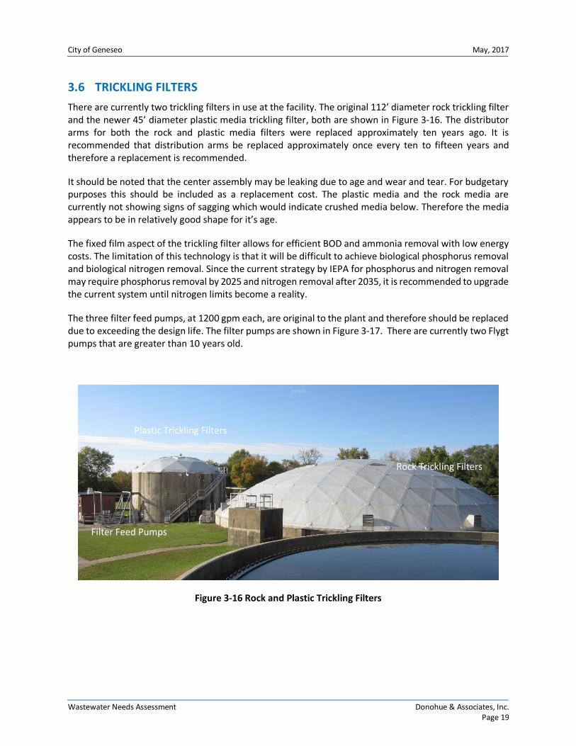
There are currently two trickling filters in use at the facility. The original 112’ diameter rock trickling filter and the newer 45’ diameter plastic media trickling filter, both are shown in Figure 3-16. The distributor arms for both the rock and plastic media filters were replaced approximately ten years ago. It is recommended that distribution arms be replaced approximately once every ten to fifteen years and therefore a replacement is recommended.
It should be noted that the center assembly may be leaking due to age and wear and tear. For budgetary purposes this should be included as a replacement cost. The plastic media and the rock media are currently not showing signs of sagging which would indicate crushed media below. Therefore the media appears to be in relatively good shape for it’s age.
The fixed film aspect of the trickling filter allows for efficient BOD and ammonia removal with low energy costs. The limitation of this technology is that it will be difficult to achieve biological phosphorus removal and biological nitrogen removal. Since the current strategy by IEPA for phosphorus and nitrogen removal may require phosphorus removal by 2025 and nitrogen removal after 2035, it is recommended to upgrade the current system until nitrogen limits become a reality.
The three filter feed pumps, at 1200 gpm each, are original to the plant and therefore should be replaced due to exceeding the design life. The filter pumps are shown in Figure 3-17. There are currently two Flygt pumps that are greater than 10 years old.
Figure 3-16 Rock and Plastic Trickling Filters
Rock Trickling Filters
Plastic Trickling Filters
Filter Feed Pumps

City of Geneseo May, 2017
Wastewater Needs Assessment Donohue & Associates, Inc. Page 20
Figure 3-17 Filter Feed Pumps
In summary, the recommended improvements due to age and deterioration of equipment are as follows:
1. Replace distributor arms for the rock filter and plastic media filter
2. Replace the center assembly
3. Replace the filter feed pumps
City of Geneseo May, 2017
Wastewater Needs Assessment Donohue & Associates, Inc. Page 21
3.7 AERATION
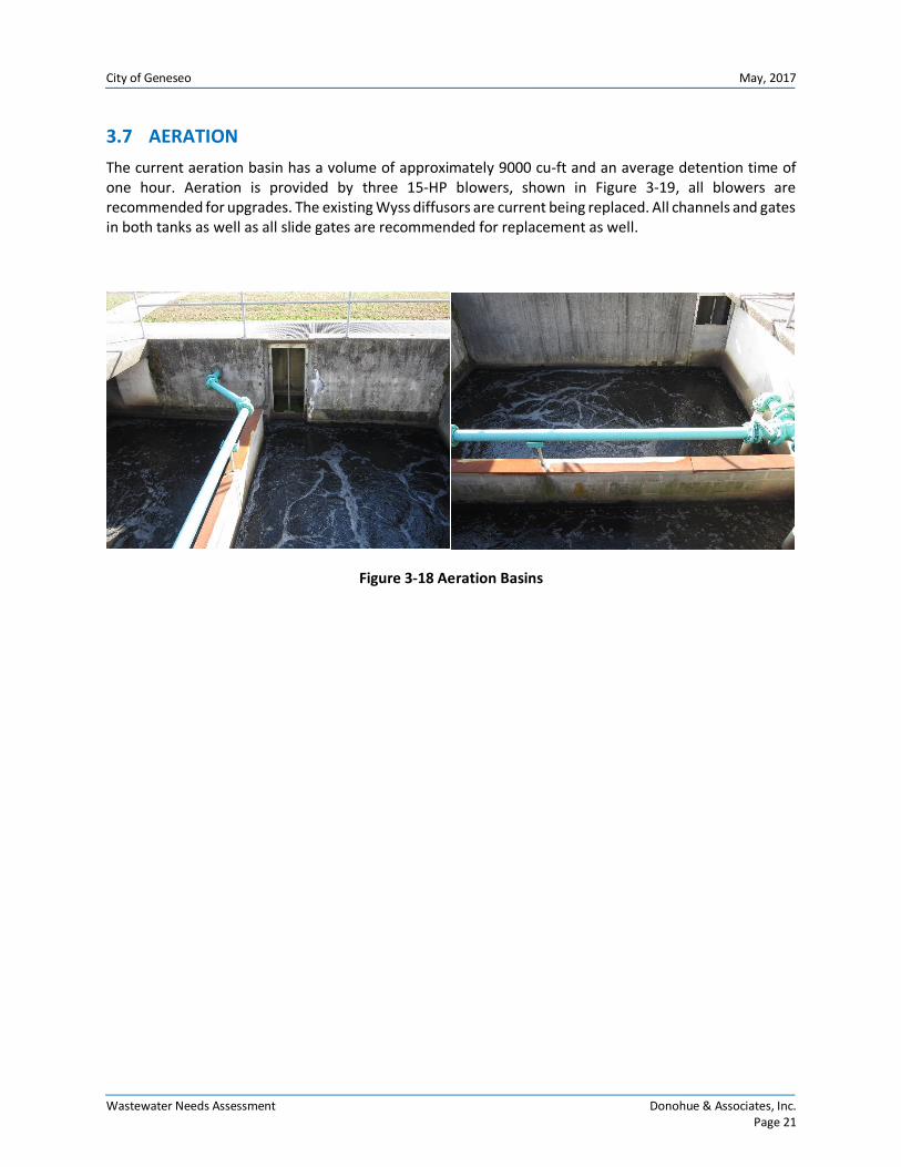
The current aeration basin has a volume of approximately 9000 cu-ft and an average detention time of one hour. Aeration is provided by three 15-HP blowers, shown in Figure 3-19, all blowers are recommended for upgrades. The existing Wyss diffusors are current being replaced. All channels and gates in both tanks as well as all slide gates are recommended for replacement as well.
Figure 3-18 Aeration Basins

City of Geneseo May, 2017
Wastewater Needs Assessment Donohue & Associates, Inc. Page 22
Figure 3-19 Three 15-HP Blowers
In summary, the recommended improvements due to age and deterioration of equipment are as follows:
1. Replace positive displacement blowers with new blowers
2. Replace gates in aeration tanks
City of Geneseo May, 2017
Wastewater Needs Assessment Donohue & Associates, Inc. Page 23
3.8 FINAL CLARIFICATION
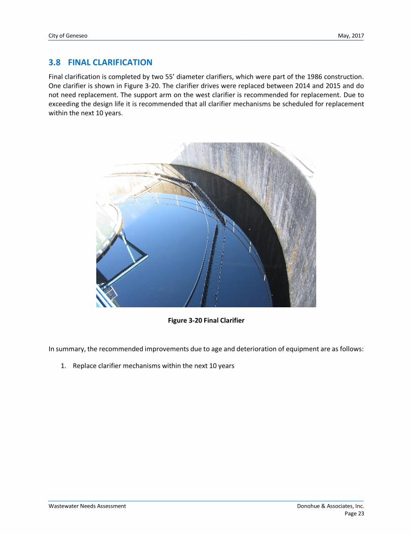
Final clarification is completed by two 55’ diameter clarifiers, which were part of the 1986 construction. One clarifier is shown in Figure 3-20. The clarifier drives were replaced between 2014 and 2015 and do not need replacement. The support arm on the west clarifier is recommended for replacement. Due to exceeding the design life it is recommended that all clarifier mechanisms be scheduled for replacement within the next 10 years.
Figure 3-20 Final Clarifier
In summary, the recommended improvements due to age and deterioration of equipment are as follows:
1. Replace clarifier mechanisms within the next 10 years

City of Geneseo May, 2017
Wastewater Needs Assessment Donohue & Associates, Inc. Page 24
3.9 SECONDARY CONTROL BUILDING
Return activated sludge pumping is completed by three 500 gpm pumps. Waste activated sludge pumping is completed by one 145 gpm pump. The secondary control building houses all of the RAS and WAS pumping, including:
1 waste sludge pump
3 return sludge pumps
VFDs
It is recommended that all sludge pumping be replaced with the same or similar equipment. The control building also contains non-potable water system pumps and a hydropneumatic tank which have reached the end of their design life. It is recommended that the pumps and the tank be replaced.
In summary, the recommended improvements due to age and deterioration of equipment are as follows:
1. Replace RAS and WAS pumps
2. Replace VFD’s with new VFD’s
3. Replace non-potable water system and hydropneumatic tank
City of Geneseo May, 2017
Wastewater Needs Assessment Donohue & Associates, Inc. Page 25
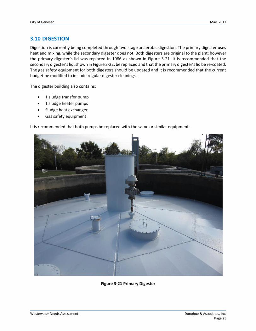
3.10 DIGESTION
Digestion is currently being completed through two stage anaerobic digestion. The primary digester uses heat and mixing, while the secondary digester does not. Both digesters are original to the plant; however the primary digester’s lid was replaced in 1986 as shown in Figure 3-21. It is recommended that the secondary digester’s lid, shown in Figure 3-22, be replaced and that the primary digester’s lid be re-coated. The gas safety equipment for both digesters should be updated and it is recommended that the current budget be modified to include regular digester cleanings.
The digester building also contains:
1 sludge transfer pump
1 sludge heater pumps
Sludge heat exchanger
Gas safety equipment
It is recommended that both pumps be replaced with the same or similar equipment.
Figure 3-21 Primary Digester

City of Geneseo May, 2017
Wastewater Needs Assessment Donohue & Associates, Inc. Page 26
Figure 3-22 Secondary Digester
In summary, the recommended improvements due to age and deterioration of equipment are as follows:
1. Replace secondary digester lid
2. Re-coat primary digester lid
3. Replace sludge heat exchanger with new sludge heat exchanger
4. Replace sludge transfer pump (part of dewatering project)
5. Replace current digester mixing system in the primary digester with new digester mixing system
6. Replace the current gas safety equipment with new gas safety equipment
City of Geneseo May, 2017
Wastewater Needs Assessment Donohue & Associates, Inc. Page 27
3.11 DEWATERING
Dewatering was done in the past using the vacuum assisted drying beds; however, problems with the drying beds have led to sludge being land applied in its liquid state. Due to resistance from the agricultural community a new dewatering system should be installed. The City has already completed a dewatering study, completed by Donohue & Associates, Inc., which recommended the installation of a rotary fan press. Based on the study, the WWTP currently produces 600,000 gallons per year of digested sludge, leading to approximately 200,000 pounds per year of dry solids. The plant staff would like to dewater one day (6-8 hours) every other week for a total of 156 to 208 hours per year. This required a minimum hydraulic capacity of 48 gpm and dry solids capacity of 962 pounds per hour. Both rotary fan presses and screw presses were investigated. Based on economic analysis the rotary fan press would be lower in both capital costs and annual costs. In addition, the fan press has a smaller footprint leading to an easier installation. The fan press initial overall project capital cost including installation would be $674,000, based on a quote from March 2014 converted to December 2016 dollars.
In summary, the recommended improvements for dewatering equipment are as follows:
1. Install rotary fan press dwatering unit
2. Replace sludge transfer pump with new transfer pump to meet the requirements of the rotary
fan press
3. Install a new emulsified polymer addition system for the rotary fan press
3.12 EFFLUENT PUMPING
Effluent pumping is utilized approximately 4 months of the year, November through February, to pump flow to the Green River. Effluent pumping is completed only to exercise the pumps. Currently there are three 1800 gpm pumps that are original to the facility. While these pumps are not used frequently it is recommended that they be replaced with the same or similar equipment and VFDs be installed. Note that a gravity line was added during the 1986 improvements. Due to high water levels in Geneseo Creek during heavy wet weather events, it is sometimes not possible to gravity flow to the Creek. In addition, with the additional future requirement for disinfection, there will be no advantage for discharging to Geneseo Creek versus the Green River. Since the effluent limits at the Green River outfall are less stringent, and since the disinfection system will require pumped flow to function, the effluent pumps will need to be used year round.
In summary, the recommended improvements due to age and deterioration of equipment are as follows:
1. Replace effluent pumps with new effluent pumps
2. Install VFD’s with new effluent pumps
3. Replace the isolation and check valves for each pump

City of Geneseo May, 2017
Wastewater Needs Assessment Donohue & Associates, Inc. Page 28
3.13 LIFT STATIONS
There are currently 9 lift stations throughout the collection system, consisting of 4 dry pit lift stations and 5 submersible pump stations.
The dry pit lift stations include:
Elk Lift Station
Chicago Lift Station
Stewart Lift Station
Crowe Lift Station
The submersible pump stations include:
Jazzercise Lift Station
Edwards Lift Station
Ash Lift Station
Cherry Lift Station
Prairie Lift Station
It is recommended that all of the dry pit lift stations be upgraded to submersible pump stations for ease of maintenance and safety. The control systems at the submersible pump lift stations should be replaced with more modern control systems.
3.14 ELECTRICAL AND CONTROL SYSTEMS
The existing treatment plant was last upgraded in 1986. There have been significant changes to electrical
codes since this upgrade and it is expected that with each individual project significant electrical upgrades
could be required. Therefore, while some dollars for electrical have been accounted for, the contingency
for each project was set at 30% due to the high level nature of the cost opinions for each project.
In terms of SCADA, which stands for Supervisory Control and Data Acquisition, the existing treatment has
very limited SCADA capabilities. We have included a line item in the overall cost opinion to account for a
stand alone SCADA implementation project.
3.15 CHANGE IN REGULATIONS
While the WWTP does not currently have disinfection or phosphorus removal requirements, new NPDES Permit will require seasonal disinfection, as indicated by the letter from IEPA shown in Appendix C, and phosphorus removal. The completion of a phosphorus removal feasibility study in anticipation of an upcoming phosphorus limit is currently being completed.
3.15.1 DISINFECTION
The facility currently has a gas chlorination system, located next to the control building. This system has not been in services for several years and is in considerable disrepair. The gaseous chlorine had been delivered in one ton cylinders in the past. Due to the potential dangers of gaseous chlorine, and the

City of Geneseo May, 2017
Wastewater Needs Assessment Donohue & Associates, Inc. Page 29
considerable revisions to the chemical feed facilities required, the City is desiring to use ultraviolet disinfection to meet the future disinfection requirements.
The excess flow lagoon currently has no disinfection capabilities. During the ultraviolet disinfection improvements, a small chemical feed facility will be installed near the lagoon overflow point to allow for disinfection before it overflows to the Geneseo Creek.
Figure 3-23 Chlorination Basin
3.15.2 PHOSPHORUS REMOVAL
While a phosphorus limit is not currently in place, a phosphorus limit compliance schedule is expected on the next issued NDPES permit. This compliance schedule will most likely require chemical phosphorus removal by 2025. While no upgrades are needed at this time, it is recommended that phosphorus removal alternative be considered during plant upgrades.
Since biological phosphorus removal is not feasible for this treatment plant a chemical addition system will need to be added. It is anticipated this system will consist of a 2,000 gallon storage tank and an alum chemical feed system. The phosphorus removal chemical feed system will be installed in a new chemical feed building.
Chlorination Basin

FLO
WSC
HEM
ATIC
Drawing Number
XX1
XX2
XX3
XX4
Drawing No.
Designed By
Checked By
Filename
Approved By
Project No.
Drawn By
Rev
isio
nN
umbe
rR
evis
ion
Des
crip
tion
Dra
wn
ByD
ate
Che
cked
By
Sheet No.
Project Date
CIT
YO
FG
ENES
EOC
API
TAL
IMPR
OVE
MEN
TPL
AN
GEN
ESEO
WA
STEW
ATE
RTR
EATM
ENT
PLAN
T
13173
02/2017
009N1.DWG
INLET SPLITTER
PLANTINFLUENT
EXCESS FLOWRETURN
MANUAL BARSCREEN
FLOWMEASUREMENTH FLUME
EXCESS FLOWPUMPING
RETURN FLOWMETERING
FLOW CONTROLVALVE
EXCESS FLOW LAGOON
MANUAL BARSCREEN
MECHANICALBAR SCREEN
FLOWCONTROLVALVE 12" PARSHALL FLUME GRIT TANK
PRIMARY CLARIFIERS
PLASTIC MEDIATRICKLING FILTER
ROCK TRICKLINGFILTER
FINAL CLARIFIERS
AERATED CHAMBER
OUTFALL 001TO GREEN RIVER
CHLORINE CONTACT TANKS
INFLUENTPUMPING
GRITPUMPING
GRIT CLASSIFIER/WASHER
GRIT TO LANDFILL FILTER FEEDPUMP
FLOWSPLITTER
AERATED CHANNELBYPASS
EFFLUENTWET WELL
RETURN SLUDGE PUMPING
WASTE SLUDGE PUMPING
RAW SLUDGEPUMPING
TRANSFER SLUDGEPUMPING SLUDGE DISCHARGE
PUMPING
PRIMARYDIGESTER
SECONDARYDIGESTER
SLUDGE HEATINGPUMPING
SLUDGE DRYING BEDS
VACUUM ASSISTEDSLUDGE BEDS
LIQUID SLUDGE TOLAND APPLICATION
DEWATERED SLUDGETO LAND FILL ORLAND APPLICATION
SUPERNATANT RETURNEDTO RAW SEWAGE PUMP STATION
WASTEWATER
SLUDGE
GRITSEPARATOR
(TOTAL CAPACITY: 4.2 MGD)
(VOLUME: 225 CU FT)(DETENTION TIME (ADF) 1.8 MIN)
(2 TANKS, 50' DIAMETER)(VOLUME EACH 183,949 GAL)
(DIAMETER 112', MEDIA DEPTH 18')(MEDIA VOLUME 73.9 KCF)
(DIAMETER 45')(MEDIA DEPTH 7.5')
(MEDIA VOLUME 28.6 KCF)
(2 BASINS, TOTAL VOLUME 9072 CU FT)
(2 TANKS, DIAMETER 55', SWD 14.5')(SURFACE SETTLING RATE (ADF) 316 GAL/D/SQF)
PRIMARYCLARIFIER 1
PRIMARYCLARIFIER 2
SECONDARYCLARIFIER 1
SECONDARYCLARIFIER 2
BYPASS
(3 PUMPS)(CAPACITY EACH 6400 GPM)
(3 PUMPS)(1 @ 1250 GPM)(1 @ 1750 GP,M)(1 @ 2000 GPM)
(1 @ 210 GPM)
(3 @1200 GPM)
(1 @ 145 GPM)
(3 @ 500 GPM)
EFFLUENT PUMPING(3 @ 1800 GPM)
(1 @ 100 GPM)
(1 @ 150 GPM)
(2 @ 150 GPM)
(1 @ 420 GPM, 2 @ 75 GPM)

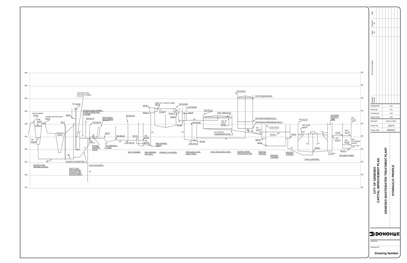
HYD
RA
ULI
CPR
OFI
LE
Drawing Number
XX1
XX2
XX3
XX4
Drawing No.
Designed By
Checked By
Filename
Approved By
Project No.
Drawn By
Rev
isio
nN
umbe
rR
evis
ion
Des
crip
tion
Dra
wn
ByD
ate
Che
cked
By
Sheet No.
Project Date
CIT
YO
FG
ENES
EOC
API
TAL
IMPR
OVE
MEN
TPL
AN
GEN
ESEO
WA
STEW
ATE
RTR
EATM
ENT
PLAN
T
13173
02/2017
001GX1.DWG
610
620
630
640
650
660
610
620
630
640
650
660
570
580
590
600 600
590
580
570
TOP OF BERM621.20
HWL618.20
LWL609.50
OVERFLOW SPILLWAY620.20
GENESEOCREEK
24"
EXCESS FLOWHOLDING LAGOON
EXCESS FLOW RETURN
30"
MH 4
624.50
TOC 632.00
INLET FLOWSPLITTER ANDEXCESS FLOWBYPASS PUMPS
EXCESS FLOWINFLUENT PUMPS
EXCESS FLOW CHANNELW/ BAR SCREEN ANDH. FLUME
TOC 621.20
TOC 619.22
MECHANICALBAR SCREEN
INV609.14
30"
PLANT INFLUENTS
BYPASSCONTROLVALVE
4"
609.70
12" PARSHALLFLUME
INV 607.64 607.81
INV 607.53
TOC 621.50
GRIT CHAMBER RAW SEWAGEWET WELL
PRIMARY CLARIFIERS TRICKLING FILTERFEED PUMPS
ROCK TRICKLING FILTER PLASTIC MEDIATRICKLING FILTER
AERATEDCHANNEL
AERATEDCHAMBER
AERATEDCHANNEL
FINAL CLARIFIERS
EFFLUENT PUMPS
HWL607.50
LWL603.00 RAW SEWAGE
PUMPS
16"
628.92
632.94POINT OF V-NOTCH WEIR632.00
632.10630.00
628.92
TOC 633.86
16"
621.85
16"
TOC 619.88
TOC 633.00
609.00
16"
INV 607.50607.00
16"
TOC 627.73DIST. ARM 625.70
TOP OFROCK624.90
BOTTOM OFUNDERDRAIN 615.50
30"
BOTTOM OF MEDIA 622.00
BOTTOM OF UNDERDRAIN 616.75
TOP OF MEDIA 640.00
TOC 643.00
30"
INV612.00
609.00
603.00
614.00
TOC 619.53
609.00
24"
TOC 621.20
SET WEIR613.50
590.34
599.10
CHLORINECONTACTTANK
601.50
INV611.92
611.80HWL611.00
LWL604.00
18"
001TO GREENRIVER
TOC621.20


NPDES Permit No. IL0021814
Notice No. SKT:16040801.bah
Public Notice Beginning Date: July 15, 2016
Public Notice Ending Date: August 15, 2016
National Pollutant Discharge Elimination System (NPDES)
Permit Program
PUBLIC NOTICE/FACT SHEET of
Draft Reissued NPDES Permit to Discharge into Waters of the State
Public Notice/Fact Sheet Issued By:
Illinois EPA Division of Water Pollution Control Permit Section 1021 North Grand Avenue East Post Office Box 19276 Springfield, Illinois 62794-9276 217/782-0610
Name and Address of Discharger: Name and Address of Facility:
City of Geneseo 115 South Oakwood Avenue Geneseo, Illinois 61254
City of Geneseo STP 207 North Stewart Street Geneseo, Illinois 61254 (Henry County)
The Illinois Environmental Protection Agency (IEPA) has made a tentative determination to issue a NPDES Permit to discharge into the waters of the state and has prepared a draft Permit and associated fact sheet for the above named discharger. The Public Notice period will begin and end on the dates indicated in the heading of this Public Notice/Fact Sheet. All comments on the draft Permit and requests for hearing must be received by the IEPA by U.S. Mail, carrier mail or hand delivered by the Public Notice Ending Date. Interested persons are invited to submit written comments on the draft Permit to the IEPA at the above address. Commentors shall provide his or her name and address and the nature of the issues proposed to be raised and the evidence proposed to be presented with regards to those issues. Commentors may include a request for public hearing. Persons submitting comments and/or requests for public hearing shall also send a copy of such comments or requests to the Permit applicant. The NPDES Permit and notice numbers must appear on each comment page. The application, engineer's review notes including load limit calculations, Public Notice/Fact Sheet, draft Permit, comments received, and other documents are available for inspection and may be copied at the IEPA between 9:30 a.m. and 3:30 p.m. Monday through Friday when scheduled by the interested person. If written comments or requests indicate a significant degree of public interest in the draft Permit, the permitting authority may, at its discretion, hold a public hearing. Public notice will be given 45 days before any public hearing. Response to comments will be provided when the final Permit is issued. For further information, please call Surinder Tandon at 217/782-0610. The following water quality and effluent standards and limitations were applied to the discharge: Title 35: Environmental Protection, Subtitle C: Water Pollution, Chapter I: Pollution Control Board and the Clean Water Act were applied in determining the applicable standards, limitations and conditions contained in the draft Permit. The applicant is engaged in treating domestic wastewater for the City of Geneseo. The length of the Permit is approximately 5 years. The effluent is discharged to the Green River through outfall 001 or to Geneseo Creek through outfall 004. The seven day once in ten year low flow (7Q10) of Green River is 46.1 cfs. The seven day once in ten year low flow (7Q10) of Geneseo CreeK is 0.03 cfs. The design average flow (DAF) for the facility is 1.5 million gallons per day (MGD) and the design maximum flow (DMF) for the facility is 4.0 MGD. Treatment consists of screening, grit removal, primary clarifiers, activated sludge, trickling filters, final clarifiers and chlorination. Sludge is treated by anaerobic digestion, drying beds and then land applied.

Public Notice/Fact Sheet -- Page 2 -- NPDES Permit No. IL0021814
This Reissued Permit does not increase the facility’s DAF, DMF, concentration limits, and/or load limits. Pursuant to the waiver provisions authorized by 40 CFR § 123.24, this draft permit is within the class, type, and size for which the Regional Administrator, Region V, has waived his right to review, object, or comment on this draft permit action. This Permit recognizes and continues the year-round disinfection exemption approved by the IEPA on June 29, 1989 and included in past NPDES permit actions since that date. It is the IEPA’s tentative decision that under Illinois Pollution Control Board regulations, the following reach of waterbody is not classified for primary contact use activities and is not subject to the fecal coliform water quality standard of 35 Ill. Adm. Code 302.209. This draft permit does not contain requirements for disinfection of the discharge from discharge numbers(s) 004. Geneseo Creek, from the facility discharge in Section 17, T17N, R3E, to the confluence with Green River has been determined to be unsuited to support primary contact activities (swimming) due to physical, hydrologic or geographic configuration. Anyone knowing of primary contact activities occurring within this water segment is invited to submit comments to the IEPA. Comments should give the nature of the activities (i.e swimming, fishing, canoeing, etc.), the location and months of the year when these activities have been observed. The IEPA is also interested in obtaining information on the proximity of residential dwellings and the accessibility of the public to this water segment. Anyone with such information is asked to submit comments to the IEPA on this draft permit action. Instructions for submitting comments are contained earlier in this document. Application is made for the existing discharge(s) which are located in Henry County, Illinois. The following information identifies the discharge point, receiving stream and stream classifications:
Discharge Number
Receiving Stream
Latitude
Longitude
Stream Classification
Integrity Rating
001 Green River 41° 29′ 05″ North 90° 11′ 15″ West General Use Not Rated
004 Geneseo Creek 41° 27′ 38″ North 90° 10′ 02″ West General Use Not Rated
005 Geneseo Creek 41° 27′ 38″ North 90° 10′ 06″ West General Use Not Rated
To assist you further in identifying the location of the discharge(s) please see the attached map.
Green River, Waterbody Segment PB-09, is listed on the draft 2014 Illinois Integrated Water Quality Report and 303(d) List as impaired. The following parameters have been identified as the pollutants causing impairment:
Potential Causes Uses Impaired
Unknown Aquatic life
Outfall 004 from the subject facility discharges to Geneseo Creek at a point where 0.03 cfs of flow exists upstream of the outfall during critical 7Q10 low-flow conditions. Geneseo Creek is classified as a General Use Water at this location. Geneseo Creek (segment PBE-01) is listed on the draft 2014 Illinois Integrated Water Quality Report and Section 303(d) List as an impaired water body for aquatic life use. The causes of impairment are given as alteration of stream-side vegetative cover (non-pollutant) and sedimentation/siltation. Geneseo Creek at this location has not been given an integrity rating in the 2008 Illinois Department of Natural Resources Publication Integrating Multiple Taza in Biological Stream Rating System. Geneseo Creek is not designated as an enhanced water pursuant to the dissolved oxygen water quality standard at this location. The next downstream segment is P-25, Rock River, and is listed on the draft 2014 Illinois Integrated Water Quality Report and Section 303(d) List as impaired for aquatic life and fish consumption uses. The cause of aquatic life use impairment is cause unknown. The causes of fish consumption use impairment are mercury and PCBs. Aesthetic quality use was not assessed. The next downstream segments are on the Mississippi River. All Illinois segments of the Mississippi River are fully supportive of aquatic life and aesthetic quality uses. There are no downstream instances of impairment due to aquatic algae, aquatic plants or dissolved oxygen.
Public Notice/Fact Sheet -- Page 3 -- NPDES Permit No. IL0021814
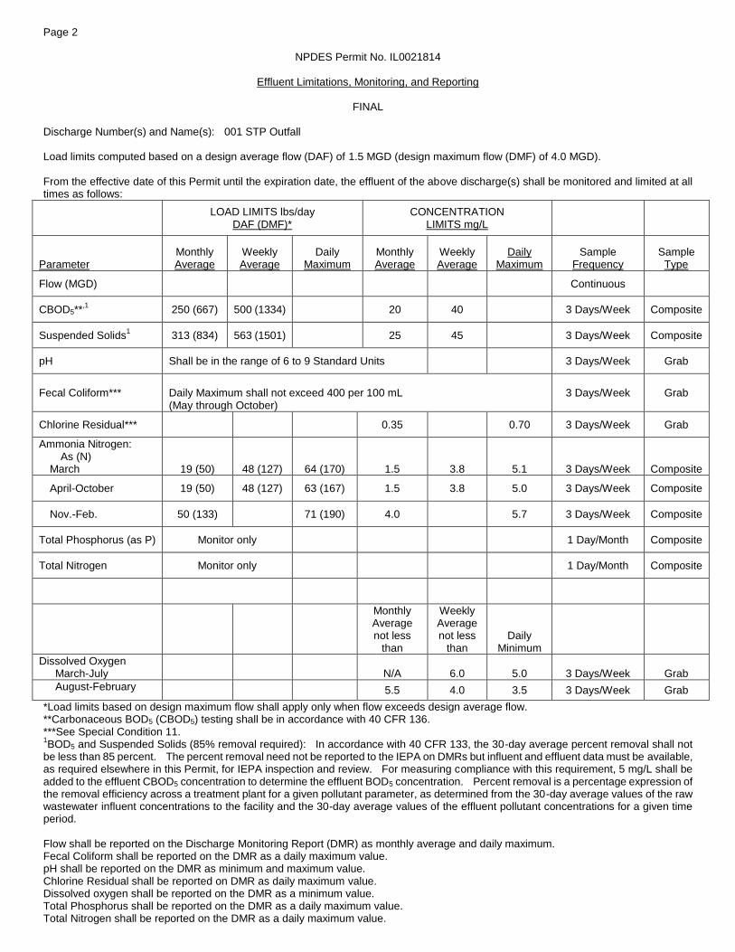
The discharge(s) from the facility is (are) proposed to be monitored and limited at all times as follows: Discharge Number(s) and Name(s): 001 STP Outfall Load limits computed based on a design average flow (DAF) of 1.5 MGD (design maximum flow (DMF) of 4.0 MGD). The effluent of the above discharge(s) shall be monitored and limited at all times as follows:
LOAD LIMITS lbs/day DAF (DMF)*
CONCENTRATION LIMITS mg/L
Parameter
Monthly Average
Weekly Average
Daily Maximum
Monthly Average
Weekly Average
Daily Maximum
Regulation
CBOD5** 250 (667) 500 (1334) 20 40 35 IAC 304.120 40 CFR 133.102
Suspended Solids** 313 (834) 563 (1501) 25 45 35 IAC 304.120 40 CFR 133.102
pH Shall be in the range of 6 to 9 Standard Units 35 IAC 304.125
Fecal Coliform
Daily Maximum shall not exceed 400 per 100 mL (May through October)
35 IAC 304.121
Chlorine Residual 0.35 0.70 35 IAC 302.208
Ammonia Nitrogen: March
19 (50)
48 (127)
64 (170)
1.5
3.8
5.1
35 IAC 355 and 35 IAC 302
April-October 19 (50) 48 (127) 63 (167) 1.5 3.8 5.0
Nov.-Feb. 50 (133) 71 (190) 4.0 5.7
Total Phosphorus (as P) Monitor only 35 IAC 309.146
Total Nitrogen Monitor only 35 IAC 309.146
Monthly Avg. not less than
Weekly Avg. not less than
Daily
Minimum
Dissolved Oxygen March-July
N/A
6.0
5.0
35 IAC 302.206
August-February 5.5 4.0 3.5
*Load Limits are calculated by using the formula: 8.34 x (Design Average and/or Maximum Flow in MGD) x (Applicable Concentration in mg/L) **BOD5 and Suspended Solids (85% removal required): In accordance with 40 CFR 133, the 30-day average percent removal shall not be less than 85 percent .
Public Notice/Fact Sheet -- Page 4 -- NPDES Permit No. IL0021814
The discharge(s) from the facility is (are) proposed to be monitored and limited at all times as follows: Discharge Number(s) and Name(s): 004 STP Outfall Load limits computed based on a design average flow (DAF) of 1.5 MGD (design maximum flow (DMF) of 4.0 MGD). The effluent of the above discharge(s) shall be monitored and limited at all times as follows:
LOAD LIMITS lbs/day DAF (DMF)*
CONCENTRATION LIMITS mg/L
Parameter
Monthly Average
Weekly Average
Daily Maximum
Monthly Average
Weekly Average
Daily Maximum
Regulation
CBOD5** 125 (334) 250 (667) 10 20 35 IAC 304.120 40 CFR 133.102
Suspended Solids** 150 (400) 300 (801) 12 24 35 IAC 304.120 40 CFR 133.102
pH Shall be in the range of 6 to 9 Standard Units 35 IAC 304.125
Fecal Coliform
Monitor only (May through October)
35 IAC 304.121
Chlorine Residual 0.05 35 IAC 302.208
Ammonia Nitrogen: March.
19 (50)
48 (127)
64 (170)
1.5
3.8
5.1
35 IAC 355 and 35 IAC 302
April-May/Sept.-Oct. 13 (33) 38 (100) 1.0 3.0
June-August 13 (33) 35 (93) 38 (100) 1.0 2.8 3.0
Nov.-Feb. 33 (87) 71 (190) 2.6 5.7
Total Phosphorus (as P) Monitor only 35 IAC 309.146
Total Nitrogen Monitor only 35 IAC 309.146
Monthly Avg. not less than
Weekly Avg. not less than
Daily
Minimum
Dissolved Oxygen March-July
N/A
6.0
5.0
35 IAC 302.206
August-February 5.5 4.0 3.5
*Load Limits are calculated by using the formula: 8.34 x (Design Average and/or Maximum Flow in MGD) x (Applicable Concentration in mg/L) **BOD5 and Suspended Solids (85% removal required): In accordance with 40 CFR 133, the 30-day average percent removal shall not be less than 85 percent.
Public Notice/Fact Sheet -- Page 5 -- NPDES Permit No. IL0021814
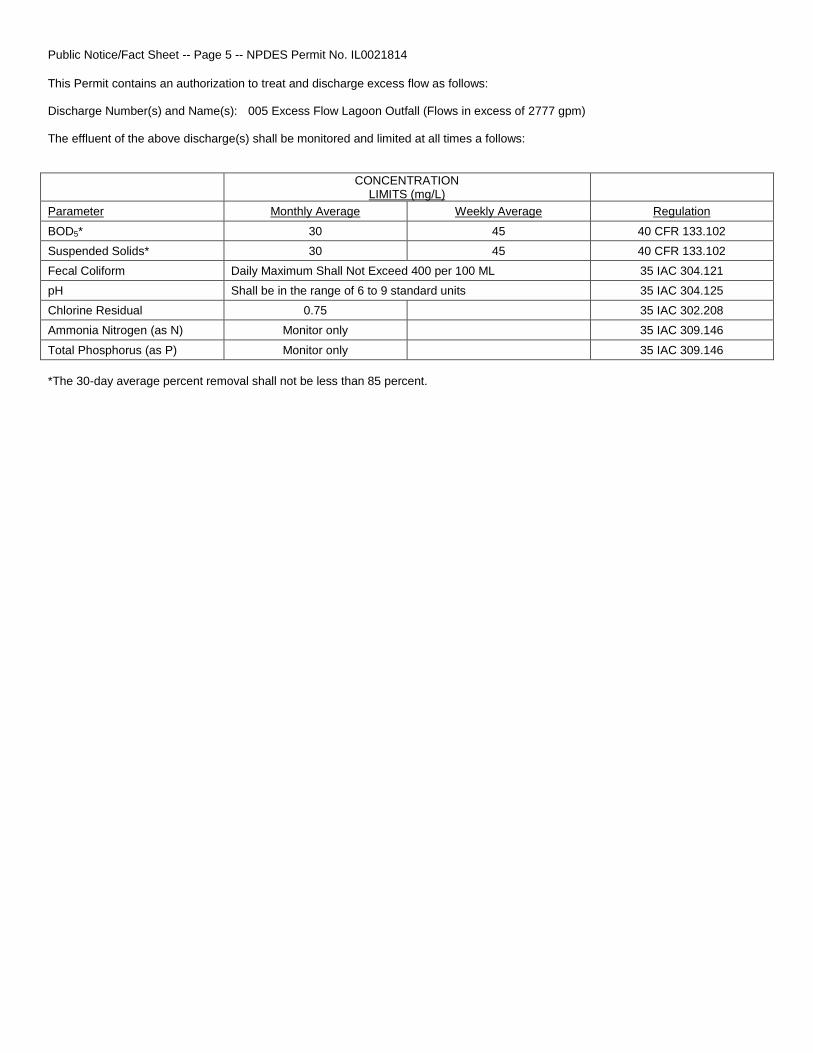
This Permit contains an authorization to treat and discharge excess flow as follows: Discharge Number(s) and Name(s): 005 Excess Flow Lagoon Outfall (Flows in excess of 2777 gpm) The effluent of the above discharge(s) shall be monitored and limited at all times a follows:
CONCENTRATION
LIMITS (mg/L)
Parameter Monthly Average Weekly Average Regulation
BOD5* 30 45 40 CFR 133.102
Suspended Solids* 30 45 40 CFR 133.102
Fecal Coliform Daily Maximum Shall Not Exceed 400 per 100 ML 35 IAC 304.121
pH Shall be in the range of 6 to 9 standard units 35 IAC 304.125
Chlorine Residual 0.75 35 IAC 302.208
Ammonia Nitrogen (as N) Monitor only 35 IAC 309.146
Total Phosphorus (as P) Monitor only 35 IAC 309.146
*The 30-day average percent removal shall not be less than 85 percent.

Public Notice/Fact Sheet -- Page 6 -- NPDES Permit No. IL0021814
This draft Permit also contains the following requirements as special conditions: 1. Reopening of this Permit to include different final effluent limitations. 2. Operation of the facility by or under the supervision of a certified operator. 3. Submission of the operational data in a specified form and at a required frequency at any time during the effective term of this
Permit. 4. More frequent monitoring requirement without Public Notice. 5. Prohibition against causing or contributing to violations of water quality standards. 6. Recording the monitoring results on Discharge Monitoring Report Forms using one such form for each outfall each month and
submitting the forms to IEPA each month. 7. The provisions of 40 CFR Section 122.41(m) & (n) are incorporated herein by reference. 8. Effluent sampling point location. 9. Controlling the sources of infiltration and inflow into the sewer system. 10. A requirement to monitor and a limit of 0.05 mg/L for residual chlorine when it is used. 11. Seasonal fecal coliform limits. 12. Monitoring for arsenic, barium, cadmium, hexavalent chromium, total chromium, copper, available cyanide, total cyanide,
fluoride, dissolved iron, total iron, lead, manganese, mercury, nickel, oil, phenols, selenium, silver and zinc is required to be conducted semi-annually beginning 3 months from the effective date.
13. Submission of annual fiscal data. 14. A requirement for biomonitoring of the effluent. 15. Submission of semi annual reports indicating the quantities of sludge generated and disposed. 16. Capacity, Management, Operations, and Maintenance (CMOM) plan. 17. Reopening of this Permit to include revised effluent limitations based on a Total Maximum Daily Load (TMDL) or other water
quality study. 18. Phosphorus Reduction Feasibility Plan 19. Phosphorus Removal Optimization Plan

Public Notice/Fact Sheet -- Page 7 -- NPDES Permit No. IL0021814

NPDES Permit No. IL0021814
Illinois Environmental Protection Agency
Division of Water Pollution Control
1021 North Grand Avenue East
Post Office Box 19276
Springfield, Illinois 62794-9276
NATIONAL POLLUTANT DISCHARGE ELIMINATION SYSTEM
Reissued (NPDES) Permit
Expiration Date: Issue Date: Effective Date:
Name and Address of Permittee: Facility Name and Address:
City of Geneseo 115 South Oakwood Avenue Geneseo, Illinois 61254
City of Geneseo STP 207 North Stewart Street Geneseo, Illinois 61254 (Henry County)
Receiving Waters: Green River and Geneseo Creek In compliance with the provisions of the Illinois Environmental Protection Act, Title 35 of the Ill. Adm. Code, Subtitle C, Chapter I, and the Clean Water Act (CWA), the above-named Permittee is hereby authorized to discharge at the above location to the above-named receiving stream in accordance with the Effluent Limitations, Monitoring, and Reporting requirements; Special Conditions and Attachment H Standard Conditions attached herein. Permittee is not authorized to discharge after the above expiration date. In order to receive authorization to discharge beyond the expiration date, the Permittee shall submit the proper application as required by the Illinois Environmental Protection Agency (IEPA) not later than 180 days prior to the expiration date.
Alan Keller, P.E. Manager, Permit Section Division of Water Pollution Control
SAK:SKT:16040801.bah
Page 2
NPDES Permit No. IL0021814
Effluent Limitations, Monitoring, and Reporting
FINAL
Discharge Number(s) and Name(s): 001 STP Outfall Load limits computed based on a design average flow (DAF) of 1.5 MGD (design maximum flow (DMF) of 4.0 MGD). From the effective date of this Permit until the expiration date, the effluent of the above discharge(s) shall be monitored and limited at all times as follows:
LOAD LIMITS lbs/day DAF (DMF)*
CONCENTRATION LIMITS mg/L
Parameter
Monthly Average
Weekly Average
Daily Maximum
Monthly Average
Weekly Average
Daily Maximum
Sample Frequency
Sample Type
Flow (MGD) Continuous
CBOD5**,1
250 (667) 500 (1334) 20 40 3 Days/Week Composite
Suspended Solids1
313 (834) 563 (1501) 25 45 3 Days/Week Composite
pH Shall be in the range of 6 to 9 Standard Units 3 Days/Week Grab
Fecal Coliform***
Daily Maximum shall not exceed 400 per 100 mL (May through October)
3 Days/Week Grab
Chlorine Residual*** 0.35 0.70 3 Days/Week Grab
Ammonia Nitrogen: As (N)
March
19 (50)
48 (127)
64 (170)
1.5
3.8
5.1
3 Days/Week
Composite
April-October 19 (50) 48 (127) 63 (167) 1.5 3.8 5.0 3 Days/Week Composite
Nov.-Feb. 50 (133) 71 (190) 4.0 5.7 3 Days/Week Composite
Total Phosphorus (as P) Monitor only 1 Day/Month Composite
Total Nitrogen Monitor only 1 Day/Month Composite
Monthly Average not less
than
Weekly Average not less
than
Daily Minimum
Dissolved Oxygen March-July
N/A
6.0
5.0
3 Days/Week
Grab
August-February 5.5 4.0 3.5 3 Days/Week Grab
*Load limits based on design maximum flow shall apply only when flow exceeds design average flow. **Carbonaceous BOD5 (CBOD5) testing shall be in accordance with 40 CFR 136. ***See Special Condition 11. 1BOD5 and Suspended Solids (85% removal required): In accordance with 40 CFR 133, the 30-day average percent removal shall not
be less than 85 percent. The percent removal need not be reported to the IEPA on DMRs but influent and effluent data must be available, as required elsewhere in this Permit, for IEPA inspection and review. For measuring compliance with this requirement, 5 mg/L shall be added to the effluent CBOD5 concentration to determine the effluent BOD5 concentration. Percent removal is a percentage expression of the removal efficiency across a treatment plant for a given pollutant parameter, as determined from the 30-day average values of the raw wastewater influent concentrations to the facility and the 30-day average values of the effluent pollutant concentrations for a given time period. Flow shall be reported on the Discharge Monitoring Report (DMR) as monthly average and daily maximum. Fecal Coliform shall be reported on the DMR as a daily maximum value. pH shall be reported on the DMR as minimum and maximum value. Chlorine Residual shall be reported on DMR as daily maximum value. Dissolved oxygen shall be reported on the DMR as a minimum value. Total Phosphorus shall be reported on the DMR as a daily maximum value. Total Nitrogen shall be reported on the DMR as a daily maximum value.

Page 3
NPDES Permit No. IL0021814
Effluent Limitations, Monitoring, and Reporting
FINAL
Discharge Number(s) and Name(s): 004 STP Outfall Load limits computed based on a design average flow (DAF) of 1.5 MGD (design maximum flow (DMF) of 4.0 MGD). From the effective date of this Permit until the expiration date, the effluent of the above discharge(s) shall be monitored and limited at all times as follows:
LOAD LIMITS lbs/day DAF (DMF)*
CONCENTRATION LIMITS mg/L
Parameter
Monthly Average
Weekly Average
Daily Maximum
Monthly Average
Weekly Average
Daily Maximum
Sample Frequency
Sample Type
Flow (MGD) Continuous
CBOD5**,1
125 (334) 250 (667) 10 20 3 Days/Week Composite
Suspended Solids1
150 (400) 300 (801) 12 24 3 Days/Week Composite
pH Shall be in the range of 6 to 9 Standard Units 3 Days/Week Grab
Fecal Coliform Monitor only (May through October)
3 Days/Week Grab
Chlorine Residual 0.05 *** Grab
Ammonia Nitrogen: As (N)
March
19 (50)
48 (127)
64 (170)
1.5
3.8
5.1
3 Days/Week
Composite
April-May/Sept.-Oct. 13 (33) 38 (100) 1.0 3.0 3 Days/Week Composite
June-August 13 (33) 35 (93) 38 (100) 1.0 2.8 3.0 3 Days/Week Composite
Nov.-Feb. 33 (87) 71 (190) 2.6 5.7 3 Days/Week Composite
Total Phosphorus (as P) Monitor only 1 Day/Month Composite
Total Nitrogen Monitor only 1 Day/Month Composite
Monthly Average not less
than
Weekly Average not less
than
Daily Minimum
Dissolved Oxygen March-July
N/A
6.0
5.0
3 Days/Week
Grab
August-February 5.5 4.0 3.5 3 Days/Week Grab
*Load limits based on design maximum flow shall apply only when flow exceeds design average flow. **Carbonaceous BOD5 (CBOD5) testing shall be in accordance with 40 CFR 136. ***See Special Condition 10. 1BOD5 and Suspended Solids (85% removal required): In accordance with 40 CFR 133, the 30-day average percent removal shall not
be less than 85 percent. The percent removal need not be reported to the IEPA on DMRs but influent and effluent data must be available, as required elsewhere in this Permit, for IEPA inspection and review. For measuring compliance with this requirement, 5 mg/L shall be added to the effluent CBOD5 concentration to determine the effluent BOD5 concentration. Percent removal is a percentage expression of the removal efficiency across a treatment plant for a given pollutant parameter, as determined from the 30-day average values of the raw wastewater influent concentrations to the facility and the 30-day average values of the effluent pollutant concentrations for a given time period. Flow shall be reported on the Discharge Monitoring Report (DMR) as monthly average and daily maximum. Fecal Coliform shall be reported on the DMR as a daily maximum value. pH shall be reported on the DMR as minimum and maximum value. Chlorine Residual shall be reported on DMR as daily maximum value. Total Phosphorous shall be reported on the DMR as daily maximum value. Total Nitrogen shall be reported on the DMR as daily maximum value. Dissolved oxygen shall be reported on the DMR as a minimum value.
Page 4
NPDES Permit No. IL0021814
Effluent Limitations, Monitoring, and Reporting
FINAL
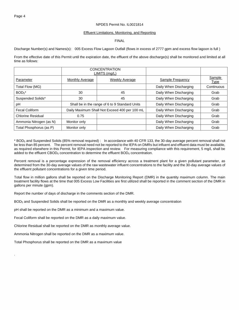
Discharge Number(s) and Names(s): 005 Excess Flow Lagoon Outfall (flows in excess of 2777 gpm and excess flow lagoon is full ) From the effective date of this Permit until the expiration date, the effluent of the above discharge(s) shall be monitored and limited at all time as follows:
CONCENTRATION LIMITS (mg/L)
Parameter Monthly Average Weekly Average Sample Frequency Sample
Type
Total Flow (MG) Daily When Discharging Continuous
BOD5* 30 45 Daily When Discharging Grab
Suspended Solids* 30 45 Daily When Discharging Grab
pH Shall be in the range of 6 to 9 Standard Units Daily When Discharging Grab
Fecal Coliform Daily Maximum Shall Not Exceed 400 per 100 mL Daily When Discharging Grab
Chlorine Residual 0.75 Daily When Discharging Grab
Ammonia Nitrogen (as N) Monitor only Daily When Discharging Grab
Total Phosphorus (as P) Monitor only Daily When Discharging Grab
* BOD5 and Suspended Solids (85% removal required) : In accordance with 40 CFR 133, the 30-day average percent removal shall not be less than 85 percent. The percent removal need not be reported to the IEPA on DMRs but influent and effluent data must be available, as required elsewhere in this Permit, for IEPA inspection and review. For measuring compliance with this requirement, 5 mg/L shall be added to the effluent CBOD5 concentration to determine the effluent BOD5 concentration. Percent removal is a percentage expression of the removal efficiency across a treatment plant for a given pollutant parameter, as determined from the 30-day average values of the raw wastewater influent concentrations to the facility and the 30-day average values of the effluent pollutant concentrations for a given time period. Total flow in million gallons shall be reported on the Discharge Monitoring Report (DMR) in the quantity maximum column. The main treatment facility flows at the time that 005 Excess Low Facilities are first utilized shall be reported in the comment section of the DMR in gallons per minute (gpm). Report the number of days of discharge in the comments section of the DMR. BOD5 and Suspended Solids shall be reported on the DMR as a monthly and weekly average concentration pH shall be reported on the DMR as a minimum and a maximum value. Fecal Coliform shall be reported on the DMR as a daily maximum value. Chlorine Residual shall be reported on the DMR as monthly average value. Ammonia Nitrogen shall be reported on the DMR as a maximum value. Total Phosphorus shall be reported on the DMR as a maximum value .
Page 5
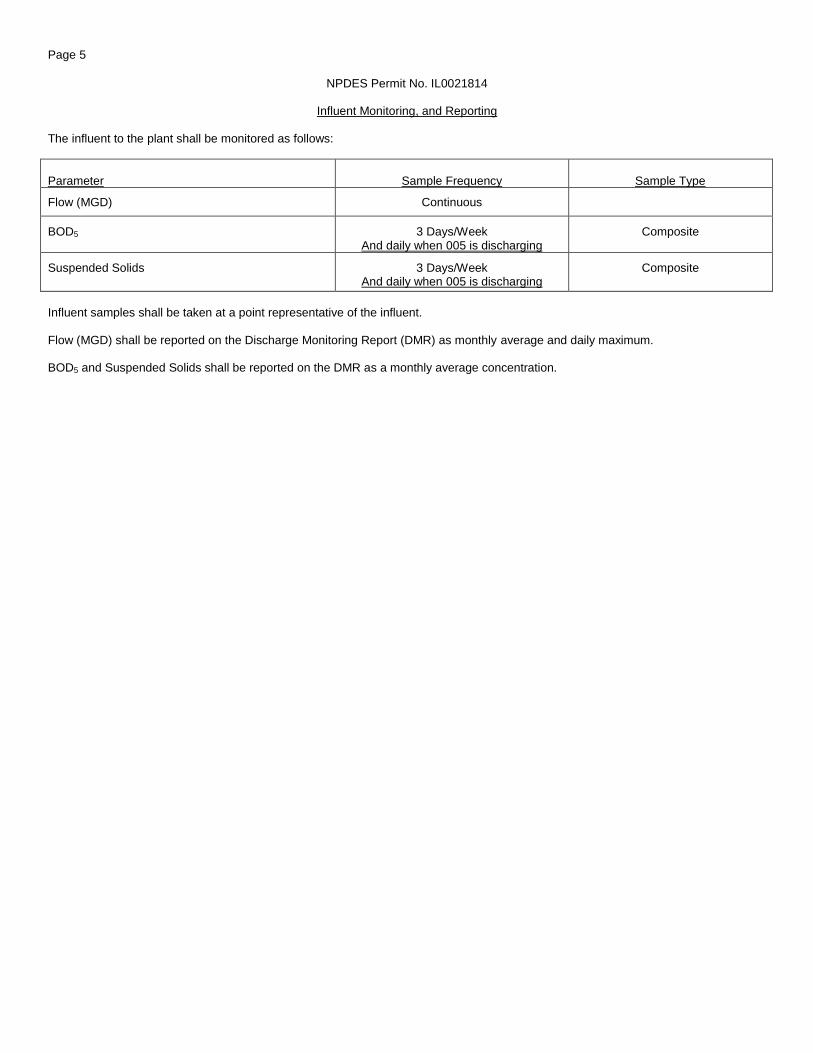
NPDES Permit No. IL0021814
Influent Monitoring, and Reporting The influent to the plant shall be monitored as follows:
Parameter Sample Frequency Sample Type
Flow (MGD) Continuous
BOD5 3 Days/Week And daily when 005 is discharging
Composite
Suspended Solids 3 Days/Week And daily when 005 is discharging
Composite
Influent samples shall be taken at a point representative of the influent. Flow (MGD) shall be reported on the Discharge Monitoring Report (DMR) as monthly average and daily maximum. BOD5 and Suspended Solids shall be reported on the DMR as a monthly average concentration.
Page 6 NPDES Permit No. IL0021814
Special Conditions
SPECIAL CONDITION 1. This Permit may be modified to include different final effluent limitations or requirements which are consistent with applicable laws and regulations. The IEPA will public notice the permit modification. SPECIAL CONDITION 2. The use or operation of this facility shall be by or under the supervision of a Certified Class 1 operator. SPECIAL CONDITION 3. The IEPA may request in writing submittal of operational information in a specified form and at a required frequency at any time during the effective period of this Permit. SPECIAL CONDITION 4. The IEPA may request more frequent monitoring by permit modification pursuant to 40 CFR § 122.63 and Without Public Notice. SPECIAL CONDITION 5. The effluent, alone or in combination with other sources, shall not cause a violation of any applicable water quality standard outlined in 35 Ill. Adm. Code 302 and 303. SPECIAL CONDITION 6. The Permittee shall record monitoring results on Discharge Monitoring Report (DMR) Forms using one such form for each outfall each month. In the event that an outfall does not discharge during a monthly reporting period, the DMR Form shall be submitted with no discharge indicated. The Permittee will be required to submit electronic DMRs (NetDMRs) instead of mailing paper DMRs to the IEPA beginning December 21, 2016. More information, including registration information for the NetDMR program, can be obtained on the IEPA website, http://www.epa.state.il.us/water/net-dmr/index.html. The completed Discharge Monitoring Report forms shall be submitted to IEPA no later than the 25th day of the following month, unless otherwise specified by the permitting authority. Permittees not using NetDMRs during the interim period before December 21, 2016 shall mail Discharge Monitoring Reports with an original signature to the IEPA at the following address:
Illinois Environmental Protection Agency Division of Water Pollution Control Attention: Compliance Assurance Section, Mail Code # 19 1021 North Grand Avenue East Post Office Box 19276 Springfield, Illinois 62794-9276
SPECIAL CONDITION 7. The provisions of 40 CFR Section 122.41(m) & (n) are incorporated herein by reference. SPECIAL CONDITION 8. Samples taken in compliance with the effluent monitoring requirements shall be taken at a point representative of the discharge, but prior to entry into the receiving stream. SPECIAL CONDITION 9. Consistent with permit modification procedures in 40 CFR 122.62 and 63, this Permit may be modified to include requirements for the Permittee on a continuing basis to evaluate and detail its efforts to effectively control sources of infiltration and inflow into the sewer system and to submit reports to the IEPA if necessary.
SPECIAL CONDITION 10. For Discharge No. 004, any use of chlorine to control slime growths, odors or as an operational control, etc. shall not exceed the limit of 0.05 mg/L (daily maximum) total residual chlorine in the effluent. Sampling is required on a daily grab basis during the chlorination process. Reporting shall be submitted on the DMR’s on a monthly basis. SPECIAL CONDITION 11. Fecal Coliform limits for Discharge Number 001 are effective May thru October. Sampling of Fecal Coliform is only required during this time period. The total residual chlorine limit is applicable at all times. If the Permittee is chlorinating for any purpose during the months of November through April, sampling is required on a daily grab basis. Sampling frequency for the months of May through October shall be as indicated on effluent limitations, monitoring and reporting page of this Permit. SPECIAL CONDITION 12. The Permittee shall conduct semi-annual monitoring of the effluent and report concentrations (in mg/l) of the following listed parameters. Monitoring shall begin three (3) months from the effective date of this permit. The sample shall be a 24-hour effluent composite except as otherwise specifically provided below and the results shall be submitted on Discharge Monitoring Report Forms to IEPA unless otherwise specified by the IEPA. The parameters to be sampled and the minimum reporting limits to be attained are as follows:

Page 7 NPDES Permit No. IL0021814
Special Conditions
STORET Minimum CODE PARAMETER reporting limit 01002 Arsenic 0.05 mg/L 01007 Barium 0.5 mg/L 01027 Cadmium 0.001 mg/L 01032 Chromium (hexavalent) (grab) 0.01 mg/L 01034 Chromium (total) 0.05 mg/L 01042 Copper 0.005 mg/L 00720 Cyanide (total) (grab)*** 5.0 ug/L 00722 Cyanide (grab) (available**** or amenable to chlorination)*** 5.0 ug/L 00951 Fluoride 0.1 mg/L 01045 Iron (total) 0.5 mg/L 01046 Iron (Dissolved) 0.5 mg/L 01051 Lead 0.05 mg/L 01055 Manganese 0.5 mg/L 71900 Mercury (grab)** 1.0 ng/L* 01067 Nickel 0.005 mg/L 00556 Oil (hexane soluble or equivalent) (Grab Sample only) 5.0 mg/L 32730 Phenols (grab) 0.005 mg/L 01147 Selenium 0.005 mg/L 01077 Silver (total) 0.003 mg/L 01092 Zinc 0.025 mg/L Minimum Reporting Limits are defined as – (1) The minimum value below which data are documented as non-detects. (2) Three to ten times the method detection limit. (3) The minimum value of the calibration range. All sample containers, preservative, holding times, analyses, method detection limit determinations and quality assurance/quality control requirements shall be in accordance with 40 CFR 136. Unless otherwise indicated, concentrations refer to the total amount of the constituent present in all phases, whether solid, suspended or dissolved, elemental or combined, including all oxidation states. *1.0 ng/L = 1 part per trillion. **Utilize USEPA Method 1631E and the digestion procedure described in Section 11.1.1.2 of 1631E. ***Analysis for cyanide (available or amenable to chlorination) is only required if cyanide (total) is detected or more than the minimum reporting limit. ****US EPA Method OIA-1677. The Permittee shall provide a report briefly describing the permittee’s pretreatment activities and an updated listing of the Permittee’s significant industrial users. The list should specify which categorical pretreatment standards, if any, are applicable to each Industrial User. Permittees who operate multiple plants may provide a single report. Such report shall be submitted within six (6) months of the effective date of this Permit to the following addresses: U.S. Environmental Protection Agency Region 5 77 West Jackson Blvd. Chicago, Illinois 60604 Attention: Water Assurance Branch Enforcement and Compliance Illinois Environmental Protection Agency Division of Water Pollution Control Attention: Compliance assurance Section, Mail Code #19 1021 North Grand Avenue East Post Office Box 19276 Springfield, Illinois 62794-9276 SPECIAL CONDITION 13. During January of each year the Permittee shall submit annual fiscal data regarding sewerage system operations to the Illinois Environmental Protection Agency/Division of Water Pollution Control/Compliance Assurance Section. The Permittee may use any fiscal year period provided the period ends within twelve (12) months of the submission date. Submission shall be on forms provided by IEPA titled “Fiscal Report Form For NPDES Permittees”.
Page 8
NPDES Permit No. IL0021814
Special Conditions
SPECIAL CONDITION 14. The Permittee shall conduct biomonitoring of the effluent from Discharge Number(s) 001 and 004. Biomonitoring 1. Acute Toxicity - Standard definitive acute toxicity tests shall be run on at least two trophic levels of aquatic species (fish,
invertebrate) representative of the aquatic community of the receiving stream. Testing must be consistent with Methods for Measuring the Acute Toxicity of Effluents and Receiving Waters to Freshwater and Marine Organisms (Fifth Ed.) EPA/821-R-02-012. Unless substitute tests are pre-approved; the following tests are required:
a. Fish - 96 hour static LC50 Bioassay using fathead minnows (Pimephales promelas).
b. Invertebrate 48-hour static LC50 Bioassay using Ceriodaphnia.
2. Testing Frequency - The above tests shall be conducted using 24-hour composite samples unless otherwise authorized by the
IEPA. Samples must be collected in the 18th, 15th, 12th, and 9th month prior to the expiration date of this Permit. 3. Reporting - Results shall be reported according to EPA/821-R-02-012, Section 12, Report Preparation, and shall be submitted to
IEPA, Bureau of Water, Compliance Assurance Section within one week of receipt from the laboratory. Reports are due to the IEPA no later than the 16th, 13th, 10th, and 7th month prior to the expiration date of this Permit.
4. Toxicity - Should a bioassay result in toxicity to >20% of organisms test in the 100% effluent treatment, the IEPA may require,
upon notification, six (6) additional rounds of monthly testing on the affected organism(s) to be initiated within 30 days of the toxic bioassay. Results shall be submitted to IEPA within (1) week of becoming available to the Permittee. Should any of the additional bioassays result in toxicity to >50% of organisms tested in the 100% effluent treatments, the Permittee shall immediately notify IEPA in writing of the test results.
5. Toxicity Reduction Evaluation and Identification - Should the biomonitoring program identify toxicity and result in notification by
IEPA, the permittee shall develop a plan for toxicity reduction evaluation and identification. This plan shall be developed and implemented in accordance with Toxicity Reduction Evaluation Guidance for Municipal Wastewater Treatment Plants, EPA/833B-99/002, and shall include an evaluation to determine which chemicals have a potential for being discharged in the plant wastewater, a monitoring program to determine their presence or absence and to identify other compounds which are not being removed by treatment, and other measures as appropriate. The Permittee shall submit to the IEPA its plan within ninety (90) days following notification by the IEPA. The Permittee shall implement the plan within ninety (90) days of notification date of the permittee above or other such date as is received by letter from IEPA.
The IEPA may modify this Permit during its term to incorporate additional requirements or limitations based on the results of the biomonitoring. In addition, after review of the monitoring results and toxicity reduction evaluation, the IEPA may modify this Permit to include numerical limitations for specific toxic pollutants and additional whole effluent toxicity monitoring to confirm the results of the evaluation. Modifications under this condition shall follow public notice and opportunity for hearing.
SPECIAL CONDITION 15. For the duration of this Permit, the Permittee shall determine the quantity of sludge produced by the treatment facility in dry tons or gallons with average percent total solids analysis. The Permittee shall maintain adequate records of the quantities of sludge produced and have said records available for U.S. EPA and IEPA inspection. The Permittee shall submit to the IEPA, at a minimum, a semi-annual summary report of the quantities of sludge generated and disposed of, in units of dry tons or gallons (average total percent solids) by different disposal methods including but not limited to application on farmland, application on reclamation land, landfilling, public distribution, dedicated land disposal, sod farms, storage lagoons or any other specified disposal method. Said reports shall be submitted to the IEPA by January 31 and July 31 of each year reporting the preceding January thru June and July thru December interval of sludge disposal operations. Duty to Mitigate. The Permittee shall take all reasonable steps to minimize any sludge use or disposal in violation of this Permit. Sludge monitoring must be conducted according to test procedures approved under 40 CFR 136 unless otherwise specified in 40 CFR 503, unless other test procedures have been specified in this Permit. Planned Changes. The Permittee shall give notice to the IEPA on the semi-annual report of any changes in sludge use and disposal. The Permittee shall retain records of all sludge monitoring, and reports required by the Sludge Permit as referenced in Standard Condition 25 for a period of at least five (5) years from the date of this Permit. If the Permittee monitors any pollutant more frequently than required by this permit or the Sludge Permit, the results of this monitoring shall be included in the reporting of data submitted to the IEPA.

Page 9
NPDES Permit No. IL0021814
Special Conditions
The Permittee shall comply with existing federal regulations governing sewage sludge use or disposal and shall comply with all existing applicable regulations in any jurisdiction in which the sewage sludge is actually used or disposed. The Permittee shall comply with standards for sewage sludge use or disposal established under section 405(d) of the CWA within the time provided in the regulations that establish the standards for sewage sludge use or disposal even if the permit has not been modified to incorporate the requirement. The Permittee shall ensure that the applicable requirements in 40 CFR Part 503 are met when the sewage sludge is applied to the land, placed on a surface disposal site, or fired in a sewage sludge incinerator. Monitoring reports for sludge shall be reported on the form titled “Sludge Management Reports” to the following address:
Illinois Environmental Protection Agency Bureau of Water Compliance Assurance Section Mail Code #19 1021 North Grand Avenue East Post Office Box 19276 Springfield, Illinois 62794-9276
SPECIAL CONDITION 16. The Permittee shall work towards the goals of achieving no discharges from sanitary sewer overflows or basement back-ups and ensuring that overflows or back-ups, when they do occur do not cause or contribute to violations of applicable standards or cause impairment in any adjacent receiving water. Overflows from sanitary sewers are expressly prohibited by this permit and by Ill. Adm. Code 306.304. In order to accomplish these goals of complying with this prohibition and mitigating the adverse impacts of any such overflows if they do occur, the Permittee shall (A) identify and report to IEPA all SSOs that do occur, and (B) develop, implement and submit to the IEPA a Capacity, Management, Operations, and Maintenance (CMOM) plan which includes an Asset Management strategy within 18 months of the effective date of this Permit or review and revise any existing plan accordingly. The Permittee shall modify the Plan to incorporate any comments that it receives from IEPA and shall implement the modified plan as soon as possible. The Permittee should work as appropriate, in consultation with affected authorities at the local, county, and/or state level to develop the plan components involving third party notification of overflow events. The Permittee may be required to construct additional sewage transport and/or treatment facilities in future permits or other enforceable documents should the implemented CMOM plan indicate that the Permittee’s facilities are not capable of conveying and treating the flow for which they are designed. The CMOM plan shall include the following elements:
A. Measures and Activities:
1. A complete map and system inventory for the collection system owned and operated by the Permittee; 2. Organizational structure; budgeting; training of personnel; legal authorities; schedules for maintenance, sewer system
cleaning, and preventative rehabilitation; checklists, and mechanisms to ensure that preventative maintenance is performed on equipment owned and operated by the Permittee;
3. Documentation of unplanned maintenance; 4. An assessment of the capacity of the collection and treatment system owned and operated by the Permittee at critical
junctions and immediately upstream of locations where overflows and backups occur or are likely to occur; use flow monitoring as necessary;
5. Identification and prioritization of structural deficiencies in the system owned and operated by the Permittee; 6. Operational control, including documented system control procedures, scheduled inspections and testing; 7. The Permittee shall develop and implement an Asset Management strategy to ensure the long-term sustainability of the
collection system. Asset Management shall be used to assist the Permittee in making decisions on when it is most appropriate to repair, replace or rehabilitate particular assets and develop long-term funding strategies; and
8. Asset Management shall include but is not limited to the following elements: a. Asset Inventory and State of the Asset; b. Level of Service; c. Critical Asset Identification; d. Life Cycle Cost; and e. Long-Term Funding Strategy.
B. Design and Performance Provisions:
1. Monitor the effectiveness of CMOM; 2. Upgrade the elements of the CMOM plan as necessary; and 3. Maintain a summary of CMOM activities.
Page 10
NPDES Permit No. IL0021814
Special Conditions
C. Overflow Response Plan:
1. Know where overflows and back-ups within the facilities owned and operated by the Permittee occur; 2. Respond to each overflow or back-up to determine additional actions such as clean up; and 3. Locations where basement back-ups and/or sanitary sewer overflows occur shall be evaluated as soon as practicable
for excessive inflow/infiltration, obstructions or other causes of overflows or back-ups as set forth in the System Evaluation Plan.
D. System Evaluation Plan:
1. Summary of existing SSO and Excessive I/I areas in the system and sources of contribution; 2. Evaluate plans to reduce I/I and eliminate SSOs; 3. Special provisions for Pump Stations and force mains and other unique system components; and 4. Construction plans and schedules for correction.
E. Reporting and Monitoring Requirements:
1. Program for SSO detection and reporting; and 2. Program for tracking and reporting basement back-ups, including general public complaints.
F. Third Party Notice Plan:
1. Describes how, under various overflow scenarios, the public, as well as other entities, would be notified of overflows
within the Permittee’s system that may endanger public health, safety or welfare; 2. Identifies overflows within the Permittee’s system that would be reported, giving consideration to various types of
events including events with potential widespread impacts; 3. Identifies who shall receive the notification; 4. Identifies the specific information that would be reported including actions that will be taken to respond to the overflow; 5. Includes a description of the lines of communication; and 6. Includes the identities and contact information of responsible POTW officials and local, county, and/or state level
officials. For additional information concerning USEPA CMOM guidance and Asset Management please refer to the following web site addresses. http://www.epa.gov/npdes/pubs/cmom_guide_for_collection_systems.pdf and http://water.epa.gov/type/watersheds/wastewater/upload/guide_smallsystems_assetmanagement_bestpratices.pdf SPECIAL CONDITION 17. This Permit may be modified to include alternative or additional final effluent limitations pursuant to an approved Total Maximum Daily Load (TMDL) Study or upon completion of an alternate Water Quality Study. SPECIAL CONDITION NO. 18. The Permittee shall, within eighteen (18) months of the effective date of this permit, prepare and submit to the Agency a feasibility study that identifies the method, timeframe, and costs of reducing phosphorus levels in its discharge to a level consistently meeting a potential future effluent limit of 1 mg/L , 0.5 mg/L and 0.1 mg/L. The study shall evaluate the construction and O & M costs of the application of these limits on a monthly, seasonal and annual average basis. SPECIAL CONDITION NO. 19. The Permittee shall develop and submit to the Agency a Phosphorus Discharge Optimization Plan within eighteen (18) months of the effective date of this permit. The plan shall include a schedule for the implementation of these optimization measures. Annual progress reports on the optimization of the existing treatment facilities shall be submitted to the Agency by March 31 of each year. In developing the plan, the Permittee shall evaluate a range of measures for reducing phosphorus discharges from the treatment plant, including possible source reduction measures, operational improvements, and minor facility modifications that will optimize reductions in phosphorus discharges from the wastewater treatment facility. The Permittee’s evaluation shall include, but not be limited to, an evaluation of the following optimization measures:
A. WWTF influent reduction measures.
1. Evaluate the phosphorus reduction potential of users.
2. Determine which sources have the greatest opportunity for reducing phosphorus (i.e., industrial, commercial, institutional,
municipal and others).
a. Determine whether known sources (i.e., restaurant and food preparation) can adopt phosphorus minimization and
water conservation plans.
b. Evaluate and implement local limits on influent sources of excessive phosphorus.
Page 11
NPDES Permit No. IL0021814
Special Conditions
B. WWTF effluent reduction measures.
1. Reduce phosphorus discharges by optimizing existing treatment processes.
a. Adjust the solids retention time for nitrification, denitrification, or biological phosphorus removal.
b. Adjust aeration rates to reduce dissolved oxygen and promote simultaneous nitrification-denitrification.
c. Add baffles to existing units to improve microorganism conditions by creating divided anaerobic, anoxic, and aerobic
zones.
d. Change aeration settings in plug flow basins by turning off air or mixers at the inlet side of the basin system.
e. Minimize impact on recycle streams by improving aeration within holding tanks.
f. Reconfigure flow through existing basins to enhance biological nutrient removal.
g. Increase volatile fatty acids for biological phosphorus removal.


Wastewater Treatment Plant Improvements2017 Capital
Cost
Headworks $887,563Excess Flow $450,929Grit $658,301Influent Pumping $272,464Primary Clarification $787,631Trickling Filters $601,738Aeration Basins $275,407Secondary Clarification $680,926Secondary Control $353,194Digestion - Primary $1,116,345Digestion - Secondary $1,324,477Dewatering $674,000Effluent Pumping $407,014Disinfection - Lagoon $199,209Disinfection - UV Plant $1,219,984Phosphorus Removal $399,240WWTP SCADA $450,000
WWTP Total $10,758,419
Lift Station ImprovementsElk Lift Station $330,000Chicago Lift Station $330,000Stewart Lift Station $330,000Crowe Lift Station $330,000Jazzercise Lift Station $40,000Edwards Lift Station $40,000Ash Lift Station $40,000Cherry Lift Station $40,000Prairie Lift Station $40,000
Lift Station Total $1,520,000
Overall Wastewater System Total $12,278,419
SUMMARY - COST OPINION

City of Geneseo - Wastewater System Capital Improvement Plan Revised 5/22/17
Inflation percent per year 3%
Cost EstimateProposed Year of
Replacement Inflated Cost 2017 2018 2019 2020 2021 2022 2023 2024 2025 2026 2027 2028 2029 2030 2031 2032
Headworks $887,563 2018 $914,190 $914,190
Excess Flow $450,929 2019 $478,391 $478,391
Grit $658,301 2023 $786,046 $786,046
Influent Pumping $272,464 2020 $297,728 $297,728
Primary Clarification $787,631 2022 $913,081 $913,081
Trickling Filters $601,738 2021 $677,261 $677,261
Aeration Basins $275,407 2021 $309,973 $309,973
Secondary Clarification $680,926 2022 $789,380 $789,380
Secondary Control $353,194 2023 $421,732 $421,732
Digestion - Primary $1,116,345 2025 $1,414,152 $1,414,152
Digestion - Secondary $1,324,477 2024 $1,628,939 $1,628,939
Dewatering $674,000 2017 $674,000 $674,000
Effluent Pumping $407,014 2020 $444,755 $444,755
Disinfection - Lagoon $199,209 2019 $211,341 $211,341
Disinfection - UV Plant $1,129,984 2019 $1,198,800 $1,198,800Design Engineering - Disinfection $90,000 2018 $90,000 $90,000
Phosphorus Removal $399,240 2025 $505,745 $505,745
WWTP SCADA $450,000 2019 $477,405 $477,405
WWTP Total $10,758,419 $12,232,917
Elk Lift Station $330,000 2017 $330,000 $330,000
Chicago Lift Station $330,000 2018 $339,900 $339,900
Stewart Lift Station $330,000 2019 $350,097 $350,097
Crowe Lift Station $330,000 2020 $360,600 $360,600
Jazzercise Lift Station $40,000 2017 $40,000 $40,000
Edwards Lift Station $40,000 2018 $41,200 $41,200
Ash Lift Station $40,000 2019 $42,436 $42,436
Cherry Lift Station $40,000 2020 $43,709 $43,709
Prairie Lift Station $40,000 2021 $45,020 $45,020
Collection System Total $1,520,000 $1,592,962
Assume Jan 1 2018 effective date $0
CMOM - 18 months $20,000 2019 $21,218 $21,218
Phosphorus Feasibility Study $16,000 2017 $16,000 $16,000
Phosphorus Discharge Optimization Plan $0 2017 $0 $0
NPDES Permit Requirements Total $36,000 $37,218
CIP Total $12,314,419 $13,863,097 $1,060,000 $1,385,290 $2,779,687 $1,146,792 $1,032,254 $1,702,460 $1,207,777 $1,628,939 $1,919,897 $0 $0 $0 $0 $0 $0 $0
Wastewater Treatment Plant
Lift Stations
NPDES Permit Requirements

General Description
Unit Cost Initial CostITEM Units Quantity ($) ($)
Architectural/Structural0 See Worksheet for Detailed Cost Breakdown 00 See Worksheet for Detailed Cost Breakdown 00 See Worksheet for Detailed Cost Breakdown 00 See Worksheet for Detailed Cost Breakdown 00 See Worksheet for Detailed Cost Breakdown 0
Mech Bar Screen (screen, screw conveyor, washpress) Each 1 310,000 310,000Install screens Each 1 46,500 46,500Conduit, Roof and Door Replacement Each 1 25,000 25,000Flow Control Valve Each 1 15,000 15,000New Influent Composite Sampler Each 1 6,000 6,000
Civil % Not Listed Above % 2% $8,050Process-Mechanical Piping % Not Listed Above % 2% $8,050Electrical % Not Listed Above % 5% $20,125Instrumentation and Control % Not Listed Above % 5% $20,125Plumbing % Not Listed Above % 2% $8,050HVAC % Not Listed Above % 2% $8,050
Subtotal 474,950
Contingency 30% 142,485
Subtotal 617,435
Contractor Overhead & Profit 25% 154,359
Total Construction Cost 771,794
Engineering 15% 115,769
Total Initial Cost 887,563
CIT OF GENESEOGENESEO WWTP
GENESEO, IL
HEADWORKS
INITIAL COST ESTIMATE
Headworks need to update screens, auger, washer and compactor, blocks around the headworks building need to be sealed. Replaceconduit on the outside of the headworks building, replace roof, replace door. Replace control valve.

General Description
Unit Cost Initial CostITEM Units Quantity ($) ($)
Architectural/Structural0 See Worksheet for Detailed Cost Breakdown 00 See Worksheet for Detailed Cost Breakdown 00 See Worksheet for Detailed Cost Breakdown 00 See Worksheet for Detailed Cost Breakdown 00 See Worksheet for Detailed Cost Breakdown 0
Influent pumps Each 3 25,000 75,000VFDs Each 3 30,000 90,000Demolition of existing structure/manhole Each 1 5,000 5,000Check valve structure new elbow connection Each 1 15,000 15,000Mag meter Each 1 5,000 5,000
Civil % Not Listed Above % 10% $19,000Process-Mechanical Piping % Not Listed Above % 5% $9,500Electrical % Not Listed Above % 10% $19,000Instrumentation and Control % Not Listed Above % 2% $3,800Plumbing % Not Listed Above % 0% $0HVAC % Not Listed Above % 0% $0
Subtotal 241,300
Contingency 30% 72,390
Subtotal 313,690
Contractor Overhead & Profit 25% 78,423
Total Construction Cost 392,113
Engineering 15% 58,817
Total Initial Cost 450,929
CIT OF GENESEOGENESEO WWTP
GENESEO, IL
EXCESS FLOW PUMP STATION
INITIAL COST ESTIMATE
Remove manhole and replace with elbow fitting (30" and 24"), replace VFD with soft starts
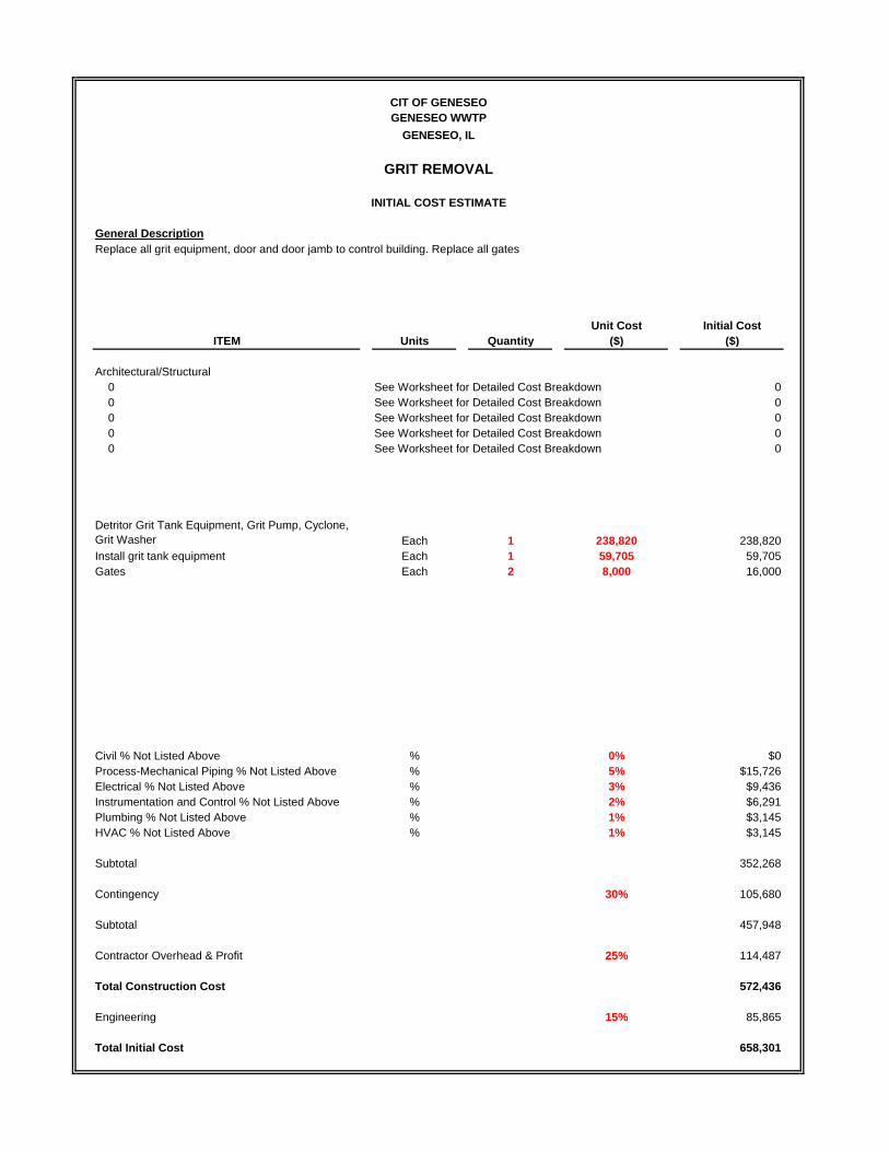
General Description
Unit Cost Initial CostITEM Units Quantity ($) ($)
Architectural/Structural0 See Worksheet for Detailed Cost Breakdown 00 See Worksheet for Detailed Cost Breakdown 00 See Worksheet for Detailed Cost Breakdown 00 See Worksheet for Detailed Cost Breakdown 00 See Worksheet for Detailed Cost Breakdown 0
Detritor Grit Tank Equipment, Grit Pump, Cyclone,Grit Washer Each 1 238,820 238,820Install grit tank equipment Each 1 59,705 59,705Gates Each 2 8,000 16,000
Civil % Not Listed Above % 0% $0Process-Mechanical Piping % Not Listed Above % 5% $15,726Electrical % Not Listed Above % 3% $9,436Instrumentation and Control % Not Listed Above % 2% $6,291Plumbing % Not Listed Above % 1% $3,145HVAC % Not Listed Above % 1% $3,145
Subtotal 352,268
Contingency 30% 105,680
Subtotal 457,948
Contractor Overhead & Profit 25% 114,487
Total Construction Cost 572,436
Engineering 15% 85,865
Total Initial Cost 658,301
CIT OF GENESEOGENESEO WWTP
GENESEO, IL
GRIT REMOVAL
INITIAL COST ESTIMATE
Replace all grit equipment, door and door jamb to control building. Replace all gates

General Description
Unit Cost Initial CostITEM Units Quantity ($) ($)
Architectural/Structural0 See Worksheet for Detailed Cost Breakdown 00 See Worksheet for Detailed Cost Breakdown 00 See Worksheet for Detailed Cost Breakdown 00 See Worksheet for Detailed Cost Breakdown 00 See Worksheet for Detailed Cost Breakdown 0
Influent pumps Each 3 20,000 60,000VFDs Each 3 10,000 30,000Valves Each 9 3,500 31,500
000000
Civil % Not Listed Above % 0% $0Process-Mechanical Piping % Not Listed Above % 5% $6,075Electrical % Not Listed Above % 10% $12,150Instrumentation and Control % Not Listed Above % 5% $6,075Plumbing % Not Listed Above % 0% $0HVAC % Not Listed Above % 0% $0
Subtotal 145,800
Contingency 30% 43,740
Subtotal 189,540
Contractor Overhead & Profit 25% 47,385
Total Construction Cost 236,925
Engineering 15% 35,539
Total Initial Cost 272,464
CIT OF GENESEOGENESEO WWTP
GENESEO, IL
INFLUENT PUMPING
INITIAL COST ESTIMATE
Replace all influent pumps and VFDs. Replace all valves.

General Description
Unit Cost Initial CostITEM Units Quantity ($) ($)
Architectural/Structural0 See Worksheet for Detailed Cost Breakdown 00 See Worksheet for Detailed Cost Breakdown 00 See Worksheet for Detailed Cost Breakdown 00 See Worksheet for Detailed Cost Breakdown 00 See Worksheet for Detailed Cost Breakdown 0
Primary Clarifier Mechanisms each 2 115,000 230,000Install primary clarifier mechanisms each 2 28,750 57,500Handrail Replacement LF 150 60 9,000Primary Sludge Pumping each 1 25,000 25,0006" Plug Valves each 6 5,000 30,000Concrete Repairs each 1 15,000 15,000
Civil % Not Listed Above % 0% $0Process-Mechanical Piping % Not Listed Above % 8% $29,320Electrical % Not Listed Above % 5% $18,325Instrumentation and Control % Not Listed Above % 2% $7,330Plumbing % Not Listed Above % 0% $0HVAC % Not Listed Above % 0% $0
Subtotal 421,475
Contingency 30% 126,443
Subtotal 547,918
Contractor Overhead & Profit 25% 136,979
Total Construction Cost 684,897
Engineering 15% 102,735
Total Initial Cost 787,631
CIT OF GENESEOGENESEO WWTP
GENESEO, IL
PRIMARY TREATMENT
INITIAL COST ESTIMATE
Replacement of primary clarifier equipment. Concrete to be repaired and the handrails be replaced with a non-embedded aluminumrailing. Primary sludge pumping should also be replaced at this time due to normal wear and tear. As well the six 6” plug valves in thesludge pit between the two clarifiers is due for replacement.
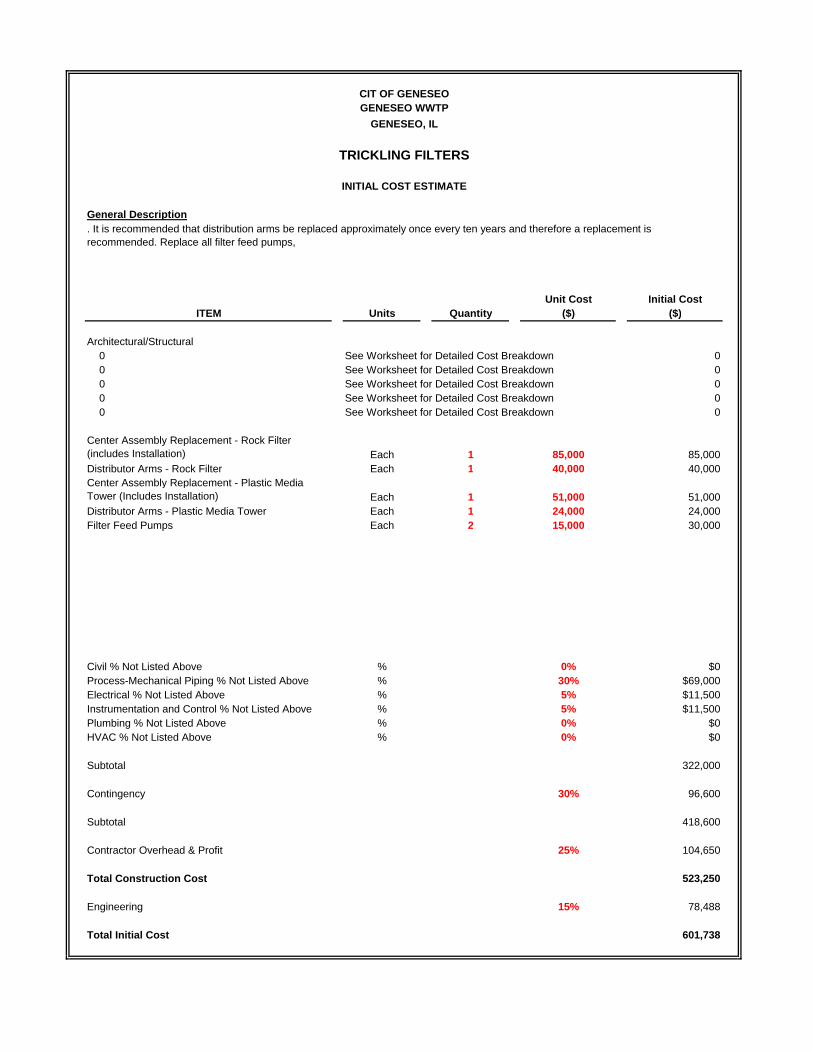
General Description
Unit Cost Initial CostITEM Units Quantity ($) ($)
Architectural/Structural0 See Worksheet for Detailed Cost Breakdown 00 See Worksheet for Detailed Cost Breakdown 00 See Worksheet for Detailed Cost Breakdown 00 See Worksheet for Detailed Cost Breakdown 00 See Worksheet for Detailed Cost Breakdown 0
Center Assembly Replacement - Rock Filter(includes Installation) Each 1 85,000 85,000Distributor Arms - Rock Filter Each 1 40,000 40,000Center Assembly Replacement - Plastic MediaTower (Includes Installation) Each 1 51,000 51,000Distributor Arms - Plastic Media Tower Each 1 24,000 24,000Filter Feed Pumps Each 2 15,000 30,000
Civil % Not Listed Above % 0% $0Process-Mechanical Piping % Not Listed Above % 30% $69,000Electrical % Not Listed Above % 5% $11,500Instrumentation and Control % Not Listed Above % 5% $11,500Plumbing % Not Listed Above % 0% $0HVAC % Not Listed Above % 0% $0
Subtotal 322,000
Contingency 30% 96,600
Subtotal 418,600
Contractor Overhead & Profit 25% 104,650
Total Construction Cost 523,250
Engineering 15% 78,488
Total Initial Cost 601,738
CIT OF GENESEOGENESEO WWTP
GENESEO, IL
TRICKLING FILTERS
INITIAL COST ESTIMATE
. It is recommended that distribution arms be replaced approximately once every ten years and therefore a replacement isrecommended. Replace all filter feed pumps,

General Description
Unit Cost Initial CostITEM Units Quantity ($) ($)
Architectural/Structural0 See Worksheet for Detailed Cost Breakdown 00 See Worksheet for Detailed Cost Breakdown 00 See Worksheet for Detailed Cost Breakdown 00 See Worksheet for Detailed Cost Breakdown 00 See Worksheet for Detailed Cost Breakdown 0
Blowers Each 3 15,000 45,000Slide Gates Each 9 7,500 67,500
Civil % Not Listed Above % 0% $0Process-Mechanical Piping % Not Listed Above % 10% $11,250Electrical % Not Listed Above % 8% $9,000Instrumentation and Control % Not Listed Above % 8% $9,000Plumbing % Not Listed Above % 2% $2,250HVAC % Not Listed Above % 3% $3,375
Subtotal 147,375
Contingency 30% 44,213
Subtotal 191,588
Contractor Overhead & Profit 25% 47,897
Total Construction Cost 239,484
Engineering 15% 35,923
Total Initial Cost 275,407
CIT OF GENESEOGENESEO WWTP
GENESEO, IL
AERATION BASINS
INITIAL COST ESTIMATE
Replace all blowers, channels and gates

General Description
Unit Cost Initial CostITEM Units Quantity ($) ($)
Architectural/Structural0 See Worksheet for Detailed Cost Breakdown 00 See Worksheet for Detailed Cost Breakdown 00 See Worksheet for Detailed Cost Breakdown 00 See Worksheet for Detailed Cost Breakdown 00 See Worksheet for Detailed Cost Breakdown 0
Clarifier Mechanisms Each 2 132,500 265,000Install clarifier mechanisms Each 2 33,125 66,250
0
Civil % Not Listed Above % 0% $0Process-Mechanical Piping % Not Listed Above % 0% $0Electrical % Not Listed Above % 5% $16,563Instrumentation and Control % Not Listed Above % 5% $16,563Plumbing % Not Listed Above % 0% $0HVAC % Not Listed Above % 0% $0
Subtotal 364,375
Contingency 30% 109,313
Subtotal 473,688
Contractor Overhead & Profit 25% 118,422
Total Construction Cost 592,109
Engineering 15% 88,816
Total Initial Cost 680,926
CIT OF GENESEOGENESEO WWTP
GENESEO, IL
FINAL CLARIFICATION
INITIAL COST ESTIMATE
Due to exceeding design life it is recommended that all clarifier mechanisms be replaced by the same or similar equipment.

General Description
Unit Cost Initial CostITEM Units Quantity ($) ($)
Architectural/Structural0 See Worksheet for Detailed Cost Breakdown 00 See Worksheet for Detailed Cost Breakdown 00 See Worksheet for Detailed Cost Breakdown 00 See Worksheet for Detailed Cost Breakdown 00 See Worksheet for Detailed Cost Breakdown 0
RAS Pumps Each 3 20,000 60,000WAS Pumps Each 1 15,000 15,000VFDs Each 4 10,000 40,000Non-potable water system, hydropneumatic tank Each 1 25,000 25,000
Civil % Not Listed Above % 0% $0Process-Mechanical Piping % Not Listed Above % 15% $21,000Electrical % Not Listed Above % 10% $14,000Instrumentation and Control % Not Listed Above % 10% $14,000Plumbing % Not Listed Above % 0% $0HVAC % Not Listed Above % 0% $0
Subtotal 189,000
Contingency 30% 56,700
Subtotal 245,700
Contractor Overhead & Profit 25% 61,425
Total Construction Cost 307,125
Engineering 15% 46,069
Total Initial Cost 353,194
CIT OF GENESEOGENESEO WWTP
GENESEO, IL
SECONDARY CONTROL
INITIAL COST ESTIMATE
Replace all sludge pumping, VFDs. Replace all RAS and WAS pumps.
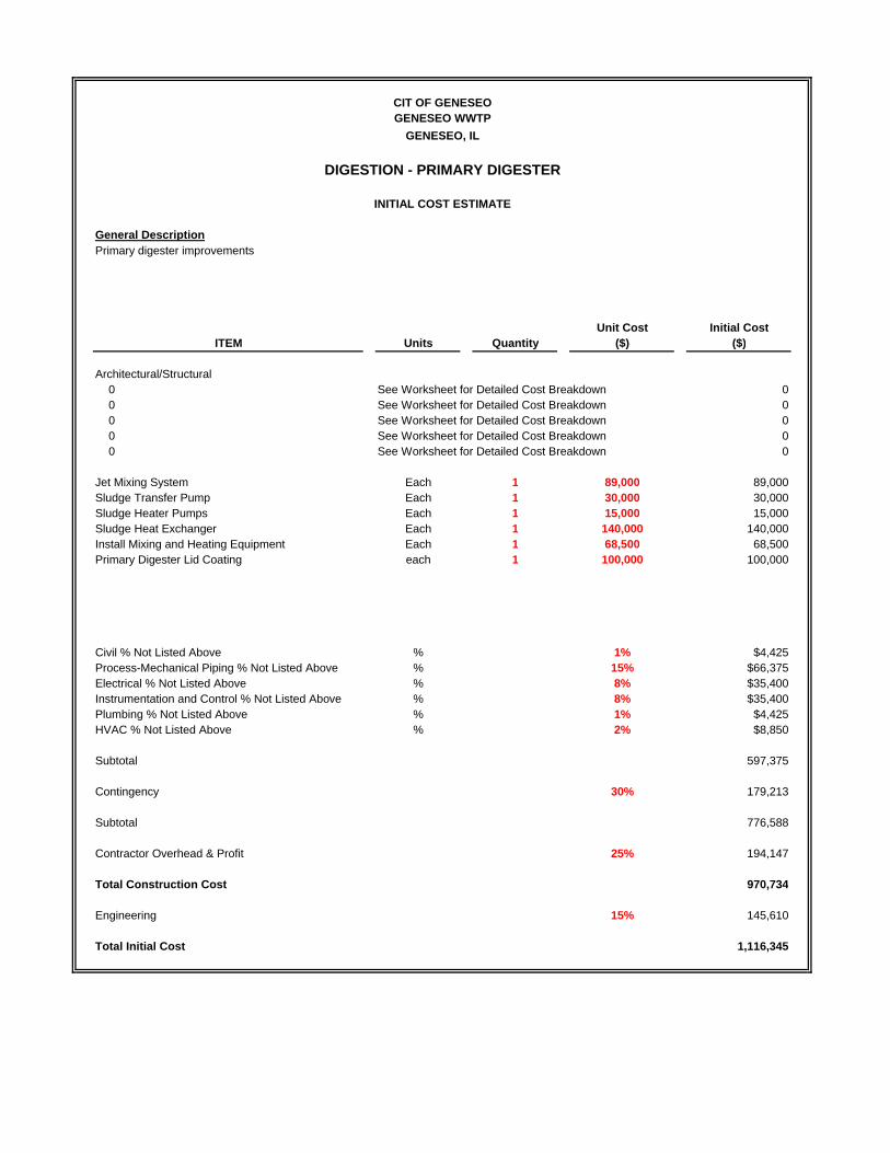
General Description
Unit Cost Initial CostITEM Units Quantity ($) ($)
Architectural/Structural0 See Worksheet for Detailed Cost Breakdown 00 See Worksheet for Detailed Cost Breakdown 00 See Worksheet for Detailed Cost Breakdown 00 See Worksheet for Detailed Cost Breakdown 00 See Worksheet for Detailed Cost Breakdown 0
Jet Mixing System Each 1 89,000 89,000Sludge Transfer Pump Each 1 30,000 30,000Sludge Heater Pumps Each 1 15,000 15,000Sludge Heat Exchanger Each 1 140,000 140,000Install Mixing and Heating Equipment Each 1 68,500 68,500Primary Digester Lid Coating each 1 100,000 100,000
Civil % Not Listed Above % 1% $4,425Process-Mechanical Piping % Not Listed Above % 15% $66,375Electrical % Not Listed Above % 8% $35,400Instrumentation and Control % Not Listed Above % 8% $35,400Plumbing % Not Listed Above % 1% $4,425HVAC % Not Listed Above % 2% $8,850
Subtotal 597,375
Contingency 30% 179,213
Subtotal 776,588
Contractor Overhead & Profit 25% 194,147
Total Construction Cost 970,734
Engineering 15% 145,610
Total Initial Cost 1,116,345
CIT OF GENESEOGENESEO WWTP
GENESEO, IL
DIGESTION - PRIMARY DIGESTER
INITIAL COST ESTIMATE
Primary digester improvements
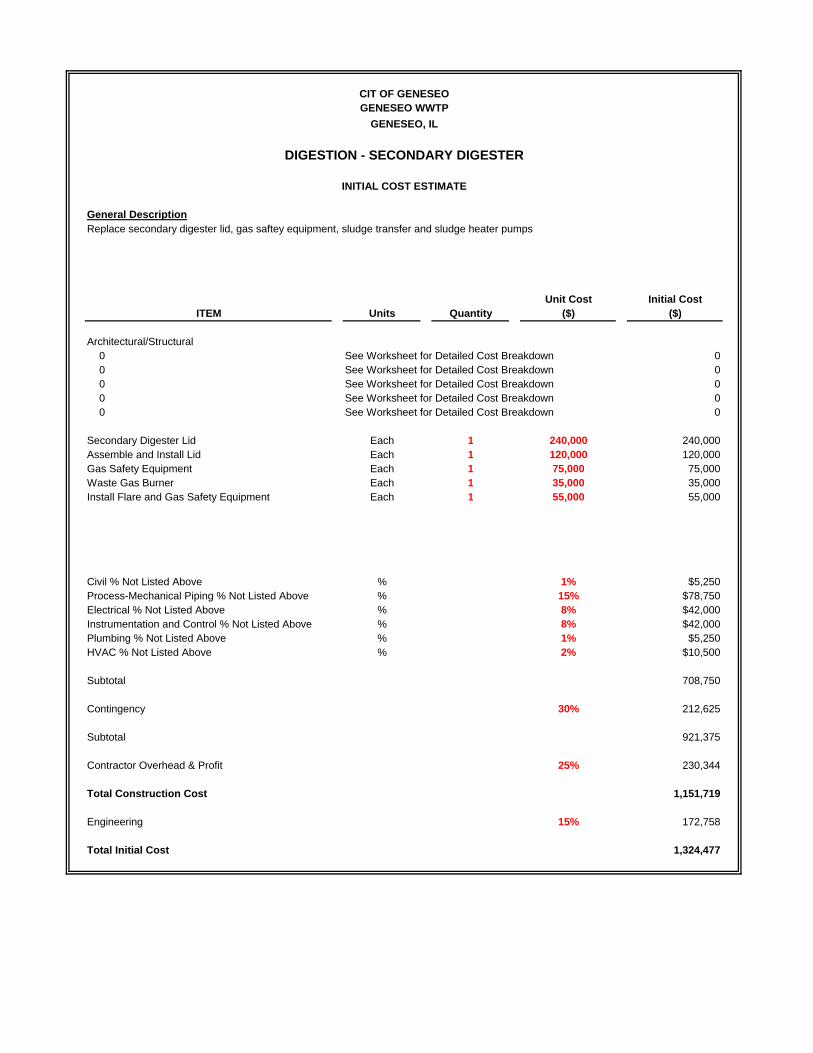
General Description
Unit Cost Initial CostITEM Units Quantity ($) ($)
Architectural/Structural0 See Worksheet for Detailed Cost Breakdown 00 See Worksheet for Detailed Cost Breakdown 00 See Worksheet for Detailed Cost Breakdown 00 See Worksheet for Detailed Cost Breakdown 00 See Worksheet for Detailed Cost Breakdown 0
Secondary Digester Lid Each 1 240,000 240,000Assemble and Install Lid Each 1 120,000 120,000Gas Safety Equipment Each 1 75,000 75,000Waste Gas Burner Each 1 35,000 35,000Install Flare and Gas Safety Equipment Each 1 55,000 55,000
Civil % Not Listed Above % 1% $5,250Process-Mechanical Piping % Not Listed Above % 15% $78,750Electrical % Not Listed Above % 8% $42,000Instrumentation and Control % Not Listed Above % 8% $42,000Plumbing % Not Listed Above % 1% $5,250HVAC % Not Listed Above % 2% $10,500
Subtotal 708,750
Contingency 30% 212,625
Subtotal 921,375
Contractor Overhead & Profit 25% 230,344
Total Construction Cost 1,151,719
Engineering 15% 172,758
Total Initial Cost 1,324,477
CIT OF GENESEOGENESEO WWTP
GENESEO, IL
DIGESTION - SECONDARY DIGESTER
INITIAL COST ESTIMATE
Replace secondary digester lid, gas saftey equipment, sludge transfer and sludge heater pumps

General Description
Unit Cost Initial CostITEM Units Quantity ($) ($)
Architectural/Structural0 See Worksheet for Detailed Cost Breakdown 00 See Worksheet for Detailed Cost Breakdown 00 See Worksheet for Detailed Cost Breakdown 00 See Worksheet for Detailed Cost Breakdown 00 See Worksheet for Detailed Cost Breakdown 0
Fan Press Each 1 674,000 674,00000
Civil % Not Listed Above % 0% $0Process-Mechanical Piping % Not Listed Above % 0% $0Electrical % Not Listed Above % 0% $0Instrumentation and Control % Not Listed Above % 0% $0Plumbing % Not Listed Above % 0% $0HVAC % Not Listed Above % 0% $0
Subtotal 674,000
Contingency 0% 0
Subtotal 674,000
Contractor Overhead & Profit 0% 0
Total Construction Cost 674,000
Engineering 0% 0
Total Initial Cost 674,000
CIT OF GENESEOGENESEO WWTP
GENESEO, IL
DEWATERING
INITIAL COST ESTIMATE
Install Fan Press
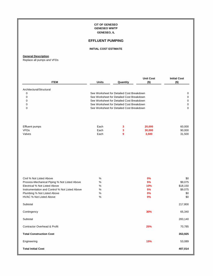
General Description
Unit Cost Initial CostITEM Units Quantity ($) ($)
Architectural/Structural0 See Worksheet for Detailed Cost Breakdown 00 See Worksheet for Detailed Cost Breakdown 00 See Worksheet for Detailed Cost Breakdown 00 See Worksheet for Detailed Cost Breakdown 00 See Worksheet for Detailed Cost Breakdown 0
Effluent pumps Each 3 20,000 60,000VFDs Each 3 30,000 90,000Valves Each 9 3,500 31,500
Civil % Not Listed Above % 0% $0Process-Mechanical Piping % Not Listed Above % 5% $9,075Electrical % Not Listed Above % 10% $18,150Instrumentation and Control % Not Listed Above % 5% $9,075Plumbing % Not Listed Above % 0% $0HVAC % Not Listed Above % 0% $0
Subtotal 217,800
Contingency 30% 65,340
Subtotal 283,140
Contractor Overhead & Profit 25% 70,785
Total Construction Cost 353,925
Engineering 15% 53,089
Total Initial Cost 407,014
CIT OF GENESEOGENESEO WWTP
GENESEO, IL
EFFLUENT PUMPING
INITIAL COST ESTIMATE
Replace all pumps and VFDs

General Description
Unit Cost Initial CostITEM Units Quantity ($) ($)
Architectural/Structural0 See Worksheet for Detailed Cost Breakdown 00 See Worksheet for Detailed Cost Breakdown 00 See Worksheet for Detailed Cost Breakdown 00 See Worksheet for Detailed Cost Breakdown 00 See Worksheet for Detailed Cost Breakdown 0
Sodium Hypchlorite Tanks and Containment Each 1 20,000 20,000Hypo Chem Feed System Each 1 21,000 21,000Bisulfite Tote Containment System Each 1 3,000 3,000Bisulfite Chem Feed System Each 1 21,000 21,000
Civil % Not Listed Above % 3% $1,950Process-Mechanical Piping % Not Listed Above % 30% $19,500Electrical % Not Listed Above % 12% $7,800Instrumentation and Control % Not Listed Above % 12% $7,800Plumbing % Not Listed Above % 2% $1,300HVAC % Not Listed Above % 5% $3,250
Subtotal 106,600
Contingency 30% 31,980
Subtotal 138,580
Contractor Overhead & Profit 25% 34,645
Total Construction Cost 173,225
Engineering 15% 25,984
Total Initial Cost 199,209
CIT OF GENESEOGENESEO WWTP
GENESEO, IL
DISINFECTION
INITIAL COST ESTIMATE
Disinfection equipment and storage at lagoon
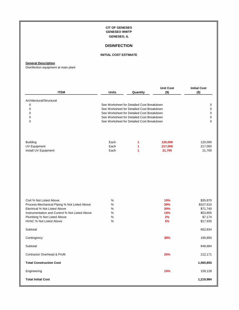
General Description
Unit Cost Initial CostITEM Units Quantity ($) ($)
Architectural/Structural0 See Worksheet for Detailed Cost Breakdown 00 See Worksheet for Detailed Cost Breakdown 00 See Worksheet for Detailed Cost Breakdown 00 See Worksheet for Detailed Cost Breakdown 00 See Worksheet for Detailed Cost Breakdown 0
Building Each 1 120,000 120,000UV Equipment Each 1 217,000 217,000Install UV Equipment Each 1 21,700 21,700
Civil % Not Listed Above % 10% $35,870Process-Mechanical Piping % Not Listed Above % 30% $107,610Electrical % Not Listed Above % 20% $71,740Instrumentation and Control % Not Listed Above % 15% $53,805Plumbing % Not Listed Above % 2% $7,174HVAC % Not Listed Above % 5% $17,935
Subtotal 652,834
Contingency 30% 195,850
Subtotal 848,684
Contractor Overhead & Profit 25% 212,171
Total Construction Cost 1,060,855
Engineering 15% 159,128
Total Initial Cost 1,219,984
INITIAL COST ESTIMATE
Disinfection equipment at main plant
CIT OF GENESEOGENESEO WWTP
GENESEO, IL
DISINFECTION

General Description
Unit Cost Initial CostITEM Units Quantity ($) ($)
Architectural/Structural0 See Worksheet for Detailed Cost Breakdown 00 See Worksheet for Detailed Cost Breakdown 00 See Worksheet for Detailed Cost Breakdown 00 See Worksheet for Detailed Cost Breakdown 00 See Worksheet for Detailed Cost Breakdown 0
Fiberglass Building / Foundation Each 1 35,000 35,000Alum Tanks and Containment Each 1 7,000 7,000Alum Chem Feed System Each 1 21,000 21,000Chem Feed Piping Each 1 15,000 15,000
Civil % Not Listed Above % 5% $3,900Process-Mechanical Piping % Not Listed Above % 30% $23,400Electrical % Not Listed Above % 12% $9,360Instrumentation and Control % Not Listed Above % 12% $9,360Plumbing % Not Listed Above % 2% $1,560HVAC % Not Listed Above % 5% $3,900
Subtotal 129,480
Contingency 30% 38,844
Subtotal 168,324
Contractor Overhead & Profit 25% 42,081
Total Construction Cost 210,405
Engineering 15% 31,561
Total Initial Cost 241,966
CIT OF GENESEOGENESEO WWTP
GENESEO, IL
PHOSPHORUS REMOVAL
INITIAL COST ESTIMATE
Alum equipment and storage, assuming old chlorine room can be used.