
Wastewater Pump Station Guideline · pump station, to establish some level of uniformity between...
49
Wastewater Pump Station Guidelines Sewers and Drainage Design Branch
Transcript of Wastewater Pump Station Guideline · pump station, to establish some level of uniformity between...

Wastewater Pump Station Guidelines
Sewers and Drainage Design Branch


CITY OF VANCOUVER WASTEWATER PUMP STATION GUIDELINES Pump Stations Engineering Services Page 2 May 2018
v. 1.0
1.0 GENERAL .1 The requirements of this specification are a general guideline
only. Detailed criteria and specific requirements should be obtained from, and reviewed with the Engineer. Good engineering design practice shall be used in the design of the sanitary sewage pumping stations.
.2 This specification is intended to give a general description of the pump station requirements and does not purport to describe all details of the equipment to be furnished.
.3 This specification is intended to improve the reliability of the pump station, to establish some level of uniformity between stations, maximize safety and efficiency of operations crews, reduce life cycle cost, and to preserve the quality of water bodies around the City of Vancouver by preventing sewage overflow from the sewage collection system.
.4 All references to Engineer shall mean the City Engineer. 1.1 Business Case .1 A business case shall be performed for all proposed new pump
stations. The business case shall include a life cycle cost analysis (“LCA”) that shall compare the construction, operation, and maintenance costs, over the life cycle of the pump station and a reasonable gravity sewer alternative. At a minimum, the following operational and maintenance costs shall be included in the LCA: labour, power consumption, equipment replacement, and routine maintenance. Pump stations will only be considered a viable option if the cost analysis clearly shows that the gravity sewers are not economically feasible.
1.2 General Requirements .1 Sanitary sewage pumping stations for the City of Vancouver
may be wet pit stations with submersible pumps, wet/dry pit stations with vertical centrifugal pumps, or self-priming suction lift pumps. The chosen configuration shall be the one that has an acceptable life cycle cost and is demonstrated to be an appropriate configuration for the site conditions.
.2 At least two pumps shall be provided. If only two units are provided, they should have the same capacity. Each shall be capable of handling the expected maximum flow. Where three or more units are provided, they must be of such capacity that with any one unit out of service, the remaining units will have capacity to handle maximum sewage flows. The station should be designed to operate at optimal efficiency for the typical flow conditions.
.3 Velocity in the discharge piping shall be: Minimum 0.6 m/s Maximum 2.5 m/s

CITY OF VANCOUVER WASTEWATER PUMP STATION GUIDELINES Pump Stations Engineering Services Page 3 May 2018
v. 1.0
.4 All building materials, paints, mechanical, and electrical components shall be free of lead, asbestos, and other hazardous materials.
.5 The station shall be designed and built to the appropriate codes for a post-disaster building.
1.3 Capacity .1 The station shall be designed to meet the maximum flow
conditions as per the City of Vancouver Sewer Design Standards.
.2 The station shall be designed to efficiently handle both existing and future flow conditions.
1.4 Odour Control .1 Where required, a suitable odour control system shall be
provided to the satisfaction of the Engineer. .2 Where odour control is not required, provisions shall be
provided to facilitate easy installation of a future odour control system.
3. At minimum, the Odour Control System shall utilize a Camfil Farr Model 3 Glide/Pack with a least 2 sets of rechargeable carbon filter panels and one disposable pre-filter panel. The system shall include a magnehelic differential pressure gauge, stainless steel ducting, airflow fans, and louvers to suit.
1.5 Station Facilities .1 On a case-by-case basis, pump station building structures may
be required by the Engineer to incorporate the following: i) Service sink, c/w paper towel holder and waste bin ii) Enclosed water closet c/w toilette paper holder. iii) Eyewash station.
1.6 Water Service .1 A 50 mm or larger water connection with approved backflow
preventer shall be provided where practical. 1.7 Landscaping .1 Sites shall be landscaped to blend with the surrounding
environment to render a pleasing overall appearance. Consideration shall be made to minimize grounds-keeping maintenance.
.2 Landscaping must be appropriate to facilitate the necessary pump station maintenance activities.
1.8 Architectural and Building Envelope .1 Sanitary sewage pumping stations shall be designed to be in
harmony with surrounding development. .2 Consideration shall be made to minimize maintenance
requirements.

CITY OF VANCOUVER WASTEWATER PUMP STATION GUIDELINES Pump Stations Engineering Services Page 4 May 2018
v. 1.0
.3 The following shall apply to any buildings or structures that form part of the pump station facility:
i) Maintenance Access a. All mechanical and electrical rooms shall contain
double doors for maintenance purposes. b. Thresholds at maintenance doors shall be flush.
ii) Buildings should have sloping roofs and overhangs. iii) Exterior doors shall be commercial quality steel,
manufactured from paintable 18ga. galvanneal sheet steel. Exterior doors shall have continuously welded seams, be vertically steel stiffened, filled with polystyrene and equipped with a welded steel top cap.
iv) Pressed steel door frames shall be of commercial quality, fully welded, 16Ga. galvanneal steel supplied with appropriate anchors to rigidly secure frames to the building structure.
v) All door hardware to be of commercial grade. 2.0 EMERGENCY OPERATION .1 The objective of this section is to provide provisions to protect
public health by preventing back up of wastewater and subsequent wastewater discharge to basements, streets, and other public and private property and to prevent the discharge of wastewater into the environment in the event of a power failure, mechanical failure, forcemain failure or other mechanism that might cause the station to not operate at full capacity.
2.1 By-Pass Pumping .1 Pumping stations shall be designed with provisions to allow
temporary by-pass pumping around the station. .2 The design shall enable the isolation of the forcemain and the
pumping station by means of isolation valves. .3 By-pass pumping discharge shall be to a quick coupling of the
“Camlock” type (150mm) located in a 1200 mm diameter manhole or buried chamber with hatch.
.4 Camlock & isolation valves shall be operable from ground level without the need for confined space entry equipment or special procedures.
.5 Specific details for the by-passing arrangement shall be confirmed with the Engineer.
2.2 Emergency Power .1 Provisions shall be made for supply of emergency power to the
pump station in the event of a power failure. Emergency power shall be provided via either of the following methods:
i) An on-site standby generator, capable of running the
station systems and maintaining the design flow capacity, shall be provided and connected to an automatic transfer

CITY OF VANCOUVER WASTEWATER PUMP STATION GUIDELINES Pump Stations Engineering Services Page 5 May 2018
v. 1.0
switch. Generator requirements shall be reviewed with the Engineer.
ii) Provisions to connect to existing City mobile generators, including a manual or automatic transfer switch, appropriate male gen-set plug and cable compatible with existing City mobile generators, and small lockable stainless steel pass-through door for the power cable and plug.
See Section 5.9 of these requirements for additional requirements.
2.3 Storage .1 If the station does not contain an on-site generator, provisions
shall be made for a minimum of 2 hours of storage during peak flow conditions (or as otherwise determined by the Engineer).
.2 If the station has an on-site generator, there is no requirement to provide storage unless otherwise determined by the City Engineer.
2.4 Overflow .1 An overflow shall be provided at the highest elevation possible
by connecting an upstream sanitary manhole to a manhole of an adjacent sanitary system or, if this is not possible, to a storm manhole. The overflow shall have a submerged inlet to limit the escape of solids, floatables and scum into the storm manhole. The overflow elevation shall be confirmed by the Engineer.
.2 An overflow connection made directly from the wet well is not acceptable.
.3 An adjustable visual marker shall be placed in the wet well to indicate the overflow elevation.
3.0 MECHANICAL 3.1 Sewage Pumps .1 Pumps shall be designed to handle raw sewage. All passages
and openings shall be large enough to pass a sphere 75 mm in diameter. For very small pump applications, the sphere diameter may be reduced to 50 mm, subject to approval by the City Engineer.
.2 The horsepower rating of the pump motors shall be such that they will carry continuously the maximum load between shutoff and runout conditions without exceeding the name plate rating.
.3 Each Pump shall have a factory applied data plate that shall contain at a minimum the following information:
i) Manufacturer’s information ii) Capacity and standard operating head of the pump iii) Pump identification number as per scheduling practice
of the record drawings. .4 Wet Well Installations

CITY OF VANCOUVER WASTEWATER PUMP STATION GUIDELINES Pump Stations Engineering Services Page 6 May 2018
v. 1.0
i) The pumps shall be the submersible type. Provisions shall be made for removal and reinstallation of the pumps without entry into the wet well.
ii) Power cables shall be factory sealed into the motor, and be of sufficient length to be connected to a junction box located above grade and outside the wet well.
iii) Each pump shall be supplied complete with an anchor frame, self-seating discharge connection, stainless steel upper and lower guide rail holders, stainless steel guide rails and stainless steel lifting chain or cable so that the pump can be removed without personnel entering the wet well. The lifting chain or cable shall be mechanically fastened to the pump and supported at the upper end by a stainless steel chain hook or clip located close to the guide rails.
iv) Anchor frames shall be epoxy coated ductile iron and supplied with stainless steel bolts, nuts, and washers.
v) Pipe supports shall be stainless steel. .5 Dry well Installations
i) Pumps and motors shall be submersible type if there is risk of dry well flooding.
ii) Pump bases whether employing a corrosion resistant pan or hand trowelled grout shall allow complete and unobstructed draining of all liquids to the floor.
.6 Pumps and Motors shall be dynamically balanced with couplers installed. In-situ testing shall be done on the installed units to confirm acceptable vibration levels. Testing to be performed by industry professionals. Vibration analysis to be included in the maintenance manual.
3.2 Sewage Piping Systems .1 75mm and smaller piping All sewage piping 75mm and smaller shall:
i) be Stainless Steel. ii) have threaded joints
.2 100mm and larger piping i) Piping 100mm to 250mm diameter to be minimum
schedule 40. ii) Piping 300mm to 600mm diameter
a. Steel Piping to have 0.375 inch minimum wall thickness.
i. Steel piping shall be internally coated and externally coated or painted to the satisfaction of the Engineer.
b. Stainless Steel piping shall be 316L SCH. 40 iii) Piping shall have flanged joints. Groove type couplings
are not to be used unless approved by the Engineer. iv) All bolts, nuts, and washers to be corrosion resistant.
Bolts, nuts, and washers shall not be painted unless

CITY OF VANCOUVER WASTEWATER PUMP STATION GUIDELINES Pump Stations Engineering Services Page 7 May 2018
v. 1.0
approved by the Engineer. If corrosion is a concern, options should be reviewed with the Engineer.
v) Field cuts in steel pipe shall be dressed with I.T.W. Devcon brushable ceramic or approved equal and allowed curing time prior to assembly.
.3 A bell mouth shall be installed on the pump intake. .4 Piping to be hydraulically and seismically restrained. .5 The main discharge header piping shall be equipped with a 2”
weldolet complete with a drain valve. .6 One spare 2” weldolet c/w isolation valve shall be provided on
the top side of the discharge header. .7 Any branches on the main header pipe for future expansion
shall be fitted with isolating discharge valve and blanking plate or blind flange.
3.3 Valves, Fittings, Appurtuences .1 Isolating valves, check valves and pump control valves shall be
located in a separate valve chamber(s) or valve room(s), away from the raw sewage wet well chamber to minimize the risks associated with Worksafe confined space entry procedures, for easily accessible operation and maintenance procedures, and to eliminate excessive corrosion of the components.
.2 Check valves i) Check valves shall be provided on the discharge side of
each pump and shall be placed in the horizontal position. ii) Check valves shall be outside lever and weight type.
Resilient seat check valves with a mechanical post indicator and manual opening operator may be considered with the approval of the Engineer.
iii) Check valves shall be flanged and of ductile iron body material.
iv) Check valves must be able to be opened manually. v) Where damaging effects of water hammer are
anticipated, valves with controlled rate of closure shall be considered.
.3 Isolating (shut-off) Valves i) Isolating valves shall be located on both suction and
discharge sides of each pump. ii) Isolation valves shall be flanged, ductile iron body
material, eccentric plug valves (full port for suction side valves) unless otherwise approved by the Engineer.
iii) Isolation valves shall be complete with: a. Gear actuator, handwheel and position indicator. b. Chain actuated handwheel or electronic
actuators where valve is located 1.8m or more above the operational floor surface.
.4 Ball Valves – 50mm and smaller (for instrument isolation or other service)

CITY OF VANCOUVER WASTEWATER PUMP STATION GUIDELINES Pump Stations Engineering Services Page 8 May 2018
v. 1.0
i) 304 Stainless Steel Construction ii) Threaded Ends (N.P.T. Standard) iii) Full Port iv) Minimum 2070 kPa (300 PSI) rated v) Lever Actuator with lock
.5 Indicating Pressure Sensors and Gauges: i) Shall be provided on the suction side and discharge side
of each pump, and on the main header pipe. ii) Gauges shall be located practically so that they function
properly and can be easily seen by operation staff performing maintenance work. Tappings into the piping for all gauges and transmitters shall be to the side of the pipe (3 or 9 o’clock position).
iii) Isolation valves and stainless steel diaphragm seals or inline ring seals shall be provided at gauges, complete with air bleeder device.
iv) Analog Gauges a. Shall be liquid filled process gauges. b. Indication shall be psi (in max 2 lb) increments,
with secondary kPa indication. c. Indication range shall be from -13 psi to +125
psi, or as determined by the City Engineer d. Shall have a 4.5” diameter face.
v) Pressure Transmitter: a. Shall be provided on the main header
discharge pipe. b. Shall be hardwired to the RTU and PLC.
.6 Air Release Valves: i) Discharge piping shall be designed where possible to
avoid localized high points. Where unavoidable, automatic air relief valves shall be installed at high points in sewage piping to prevent air locking.
ii) Air release valves shall be Vent-O-Mat RGXb series, or alternative approved by the Engineer.
iii) The air release valves shall be exhausted to the wet well.
iv) Air release valves shall be installed c/w an isolation valves.
4.0 GENERAL FACILITY REQUIREMENTS 4.1 General Chamber Requirements
.1 Chamber roofs: i) Shall be designed to withstand full HS-20 loading in
roadways and full traffic areas and incidental H-20 in non-traffic areas.
ii) Shall be flush or below grade and not present a trip hazard where practical. Design shall consider surrounding landscaping.
CITY OF VANCOUVER WASTEWATER PUMP STATION GUIDELINES Pump Stations Engineering Services Page 9 May 2018
v. 1.0
iii) Shall be outfitted with support for davit cranes or other hoisting mechanism as appropriate for equipment contained within the chamber or personnel that may enter the chamber (see Section 4.4 for information on lifting davits).
.2 Access hatches (where applicable): i) Shall be appropriately sized for removal of equipment
and entry and exit of personnel. ii) Shall be designed to withstand full HS-20 loading in
roadways and full traffic areas and incidental H-20 in non-traffic areas.
iii) Shall be mounted flush and not present a tripping hazard.
iv) Shall be equipped with a locking mechanism. On exterior access hatches this shall consist of a watertight slam-lock mechanism and an oversized recessed padlock hasp with a flush hinged cover plate which does not present a tripping hazard. Interior hatches may only require a slam-lock mechanism.
v) Shall have appropriate slip protection surface. vi) Shall have gas spring assisted lids which lock in the
open position. vii) Chambers containing motors or other electrically
sensitive equipment shall have gutters in the hatch that collects and prevents water from dripping onto equipment. The water from the gutter shall be piped to a drain or sump pump.
viii) Telescoping ladder extension safety posts shall be installed at all man entry points to underground chambers.
ix) Shall contain fall protection grids (fall protection meshing is not acceptable).
.3 Lighting requirements shall be reviewed with the City Engineer on a case-by-case basis.
.4 Ventilation requirements shall be reviewed with the City Engineer on a case-by-case basis.
.5 Ladder/platform requirements shall be reviewed with the City Engineer on a case-by-case basis.
4.2 Wet well Requirements .1 If constant speed pumps are used, storage volume of the wet
well shall be adequate to prevent the short cycling of the pumps (i.e. frequent starting and stopping).
.2 All electrical equipment in the wet well shall be explosion proof. .3 Where four or more pumps are to be installed the wet well shall
be divided into at least two sections so that any section maybe taken out of service for inspection, cleaning, or repairs. Each section of the wet well shall have an individual inlet equipped with a sluice gate designed to divert flow from the section that
CITY OF VANCOUVER WASTEWATER PUMP STATION GUIDELINES Pump Stations Engineering Services Page 10 May 2018
v. 1.0
has been removed from service. Each of the set wet well sections shall be interconnected with a sluice gate that will be open during normal station operation. Access shall be provided for each section.
.4 Platforms shall be removable if required to access or remove equipment.
.5 Provisions shall be provided for removal of pumps and mixers through the use of overhead cranes or removable lifting davits without the need for wet well entry.
.6 Ladders shall be constructed of non-corrosive material, and platforms and handrails shall be constructed of fibreglass where possible and anchored using stainless steel fasteners.
.7 Where wet well walls are concrete, the concrete shall be epoxy coated as appropriate.
.8 Sloping sump bottoms and filleted corners shall be provided in the wet well to direct sewage flow to the pump suction inlets and to minimize solids deposition on the bottom.
.9 Ventilation requirements to be reviewed with the Engineer.
.10 Where used, inlet baffles shall be stainless steel.
.11 A sluice gate shall be installed at the inlet to the wet well. Sluice gate shall be designed and be of appropriate material for a wet well application. Mounting shall be as per the manufacturer’s instructions.
.12 Mixer i) A submersible mixer pump suitable for operation in
sewage pump station wet well shall be installed, except in specially designed self-cleaning wet wells.
ii) The mixer shall have stainless steel construction throughout for all mounting hardware including lifting cable, support cable, lift cable holding clamp, mast, supports and related installation/operating hardware.
iii) Where appropriate, the mixer shall be Flygt SR-4630. Other mixers may only be used with the approval of the Engineer.
iv) The mixer pump shall be mounted in a manner that will allow removal and installation without personnel entering the wet well.
.13 Wet well shall not leak.
4.3 Dry well Requirements .1 The dry well shall be ventilated by a mechanical air exhaust
system. Ventilation requirements shall be discussed with Engineer.
.2 Drainage i) Dry well floors shall be constructed to drain by gravity
into trench drains channelled to a sump. Minimum slope shall be 1%.
ii) Trench drains shall be covered with corrosion resistant gratings.

CITY OF VANCOUVER WASTEWATER PUMP STATION GUIDELINES Pump Stations Engineering Services Page 11 May 2018
v. 1.0
iii) A sump pump shall be installed in the sump, and discharge above the higher of either the highest possible water level in the wet well, or 0.3 meters above the 100 year flood level.
iv) The sump pump shall be operated by a float control system and equipped with an external float and replaceable float switch.
v) Sump pump shall be equipped with a 4-20 mA output and analog signal to be brought to the PLC.
.3 All lift stations shall be sized to conform with the following clearances unless otherwise approved:
i) A minimum of 0.6m between the pump/motor assembly’s projections and the inside station wall surface.
ii) A minimum of 0.9m clear floor space between adjacent pump/motor assemblies.
iii) Adequate horizontal and vertical clearance shall be provided for removal of all equipment that requires disassembling and/or lifting for removal or for other maintenance purposes.
iv) Pumps and motor assembly shall be accessible for maintenance on three sides without having to climb over piping or other pieces of equipment.
v) Detailed analysis and review of the working clearance shall be reviewed for all equipment installations.
4.4 Lifting Davits
.1 Where portable lifting davits are required, the lifting davit shall: i) Have a minimum lifting capacity of 250 kg. ii) Have adjustable Boom Length and Height iii) Break down for easy storage iv) Rotate 360 degrees v) Have a spur gear hand winch that is self-breaking in
forward and reverse direction vi) Have a stainless steel rope affixed to a swivelling catch
type hook. vii) Have a lifting height suitable for intended use including
considering size of equipment that may need to be lifted out of the chamber.
.2 The lifting davit receiver shall: i) Have a flush mounted base (for installation through
cored hole in concrete slab) so as to not pose a tripping hazard.
ii) Have a cover plate or plug that shall be anchored down when davit not in use. Plate and anchoring components shall be countersunk so as to not pose a tripping hazard.

CITY OF VANCOUVER WASTEWATER PUMP STATION GUIDELINES Pump Stations Engineering Services Page 12 May 2018
v. 1.0
4.5 Cranes .1 Where permanent cranes are installed in the pump station, the
crane manufacturer’s technical representative shall make a complete operational and performance test of the crane. The crane shall be certified in place and be labelled with the appropriate Load Rating Decal.
4.6 Flow Measurement
.1 Flow measurement devices are required for all pumping stations.
.2 Flow measuring devices shall be properly located for accurate readings.
.3 Flow monitoring equipment shall be able to determine and record rate of flow, duration, volumetric sum, and frequency for each pump and each bypass, and interface with City SCADA requirements.
.4 The approved flow meter is the Siemens Sitrans FM Magflow MAG 5100 W electromagnetic flowmeter tube and MAG 6000 remote mounted transmitter. Other flow measuring devices may only be used with the approval of the Engineer.
5.0 ELECTRICAL 5.1 General .1 The installation shall comply with requirements of the current
edition of the Canadian Electrical Code as amended by the province of British Columbia and the local authority having jurisdiction.
.2 All materials shall be new, and all electrical work shall comply with the latest revisions of CSA standards and codes, and satisfy regulatory requirements of authorities having jurisdiction. Where equipment or materials are specified by technical description only, they shall be of the best commercial quality obtainable for the purpose. All work shall be executed in a neat and professional workmanlike manner by qualified tradespeople.
.3 The Electrical Contractor shall obtain all required electrical permits, and arrange for all necessary electrical inspections, including final inspection, and provide copies of all permits and inspections to the Engineer.
.4 Record Drawings i) The Electrical Contractor shall accurately record daily, all
conduit, fixtures, and equipment as actually installed on the project. Any changes to the contract work shall be similarly recorded on the redline drawings.
ii) As built drawings shall be provided for all control panels, motor control centre, and all new and modified connections to the existing RTU panel. All wiring and components such as relays, contacts, terminal blocks,

CITY OF VANCOUVER WASTEWATER PUMP STATION GUIDELINES Pump Stations Engineering Services Page 13 May 2018
v. 1.0
devices and instruments shall be labelled and identified in the field and on the as-built drawings. As-built drawings shall include a complete bill of materials for each MCC section, equipment layout diagrams, and detailed motor control wiring diagrams for each individual load including all PLC and RTU signal terminations and wire tags.
iii) Wires with terminations in different enclosures shall be labelled with heat shrink labels identifying the starting and landing terminal on each end of the wire. Discuss labelling convention with City.
.5 House Power i) A separate house panel-board, 42cct type, 225A rated, 3-
phase, 4wire, copper bus, fully rated shall be provided for the station
ii) All lights and power receptacles shall be fed from the house panel
iii) The receptacles shall be arranged to be suitable for use by operations and maintenance personnel
.6 The following wires shall be separated from each other by use of separate conduits or cables:
i) 120/240 VAC power ii) 24 VDC power and control iii) analog and data.
.7 The uniformity of manufacture shall be maintained for any particular item throughout the project.
.8 The engineer reserves the right to modify the location of any equipment to within 3m of points indicated within the plans without extra charges providing the Contractor is advised prior to installation.
.9 An arc flash hazard assessment shall be completed as per the latest revision of CSA Z462.
.10 Spare wires shall be labelled as ‘spare’ and shall be terminated to spare terminal blocks. Wires with terminations in different enclosures shall be labelled with heat shrink labels identifying the starting and landing terminal on each end of the wire. Contractor to review labelling convention with the City prior to start of work.
5.2 Labelling of Conduits, Cables, and Enclosures .1 All conduits, cables, and junction boxes shall be labelled. .2 Labelling shall reflect the drawings and City naming
convention. .3 All name plates shall be black lamicoid with white engraved
letters. The use of “Dymo” type tape markers will not be permitted.
.4 Name plates shall reflect naming convention on the record drawings.
.5 Arc flash warning labels shall be installed as per CSA Z462.

CITY OF VANCOUVER WASTEWATER PUMP STATION GUIDELINES Pump Stations Engineering Services Page 14 May 2018
v. 1.0
5.3 Control Systems .1 The basic operation and control philosophy for City sewage
pump stations is described in Appendix B. .2 The control panel door layout shall be based on the drawing
shown in Appendix C. .3 Programmable Logic Controller (PLC)
i) There shall be redundant PLC’s, with the secondary PLC set in a cold standby configuration. a. Failure of the primary system shall automatically
cause a switch to the secondary system utilizing timer relays.
b. The secondary switch shall not automatically switch back to the primary system. Switch back to the primary system shall be done manually through a hardwire switch.
c. PLC cabinetry shall show status of which system is active.
d. A manual switching option shall also be provided. ii) The PLC shall be an Allen Bradley CompactLogix
System or similar approved by the City Engineer. iii) The following PLC modules are approved for use:
a. 1769-L32E COMPACTLOGIX ENET, 750K MEM
b. 1769-PA4 1769 POWER SUPPLY 120V/220V AC
c. 1769-IQ32 32 POINT 24V DC INPUT MODULE
d. 1769-OW16 16 POINT AC/DC RELAY OUTPUT MODULE
e. 1769-IF8 8 CHANNEL, VOLTAGE/CURRENT I/P, ANALOG INPUT MODULE
f. 1769-OF4CI 4 CHANNEL, CURRENT ISOLATED, ANALOG OUTPUT MODULE
g. 1769-ECR RIGHT END CAP TERMINATOR
h. MVI69-MNET PROSOFT MODBUS TCP/IP COMM MODULE
Other modules may only be used with the approval of the City Engineer.
iv) Interface of all alarms between PLC and RTU shall be hardwired with the exception of some Modbus registers to be approved by the City Engineer.
v) A list of typical physical inputs and outputs to the PLC’s for sewage pump stations has been included in Appendix A. This list may change from time to time and the most up to date list should be obtained from the City. The I/O will vary depending on the type and number of equipment used in the station. All tag

CITY OF VANCOUVER WASTEWATER PUMP STATION GUIDELINES Pump Stations Engineering Services Page 15 May 2018
v. 1.0
names and descriptors used in the PLC programming must be consistent with City I/O requirements, and should be consistent between the PLC and the RTU. A formal list of all tags to be used in the PLC programming (including tagname, function, and descriptor) shall be submitted for review and approval by the City.)
vi) The DC power supply shall be redundant OMRON 240W, 10A, 24VDC, S8VS-24024AP units, with either a primary/secondary, or parallel configuration as approved by the City Engineer.
.4 Operator Interface (HMI) i) The local operator interface shall consist of a twin Allen-
Bradley Panelview HMI screens. The acceptable part numbers are;
10” screen: 2711P-T10C22D9P 15” screen: 2711P-T15C22D9P. Both units require 24VDC for power, and run a Windows CE operating system. The 15” screens shall be used within the pump control panel within pump station buildings, the 10” screens maybe used in the RTU panels. HMI panels for pump control panels located in kiosks shall be determined on a case by case basis. ii) This setup shall be in a redundant (cold standby)
configuration. The redundant configuration shall be as per Section 5.3.3 i).
iii) The operator interface (touchscreens) shall be located on the face of the control panel (control panel layout in Appendix C).
iv) Pumps that are located out of visual sight from the MCC shall be provided with two start/stop controls.
.5 Switches i) Rotary switches
a. Rotary switches shall be included on the control panel cabinet door for the following:
i. HOA (Hand-Off-Auto) pump control for each discharge pump
ii. HOA (Hand-Off-Auto) pump control for each mixer pump (if station equipped)
iii. Level Transmitter primary/secondary selection
iv. PLC primary/secondary selection v. Control Power primary/secondary
selection b. Rotary switches shall be 30mm diameter, NEMA
4X, with contact blocks c. Switches shall be IDEC or Allen Bradley with the
approval of the Engineer. Other Switches may

CITY OF VANCOUVER WASTEWATER PUMP STATION GUIDELINES Pump Stations Engineering Services Page 16 May 2018
v. 1.0
only be used with the approval of the City Engineer.
ii) Push button switches a. Push button switches shall be included on the
control panel cabinet door for the following: i. Pump Sequence Selector ii. Alarm Reset/Lamp Test
b. Push button switches shall be 30mm diameter, NEMA 4X, oil-tight, with contact blocks
c. Permitted switch manufacturers include: Allen Bradley, and IDEC. Other Switches may only be used with the approval of the City Engineer.
iii) E-STOP a. An E-STOP shall be provided near the location
of each pump control. b. Each E-STOP shall have:
i. a red mushroom operator ii. push-pull/twist action iii. switch shroud to prevent accidental
stops iv) Toggle switches are not permitted.
.6 Indication Lights i) The following indication lights shall be included on the
control panel cabinet door: a. HOA (Hand-Off-Auto) Pump Status Indication
i. Pump Status Indication shall be illuminated with the following colour scheme:
HAND: Amber or Orange OFF: Red AUTO: Green RUN Status: Yellow ii. Permitted indication device is IDEC
SLC30N-0202-DD2F. Other indication devices may only be used with the approval of the City Engineer.
b. Primary/Secondary Indicators i. All Primary/Secondary Indicators shall
be illuminated with the following colour scheme:
PRIMARY: Yellow SECONDARY: Blue
ii. Permitted indication device is IDEC SLC30N-0201-DD2H. Other indication devices may only be used with the approval of the City Engineer.
.7 Convenience Connections. i) A 120V power receptacle shall be provided inside the
control panel. This receptacle shall not be connected to the uninterruptable power source if station equipped.
CITY OF VANCOUVER WASTEWATER PUMP STATION GUIDELINES Pump Stations Engineering Services Page 17 May 2018
v. 1.0
ii) An ethernet port shall be provided inside the control panel for laptop connectivity.
.8 Wiring i) 600 volt wiring shall be copper TECK90 or RW90, with
1000 volt insulation and bearing CSA labelling. ii) 600 volt wiring colour coding:
Phase A red Phase B black Phase C blue Neutral white Ground green
iii) 120/240 volt wiring shall be copperTECK90 or RW90, with 600 volt insulation and bearing CSA labelling.
iv) No conductor smaller than #12 AWG shall be used for branch circuit wiring.
v) Approved TECK90 connectors are to be utilized. XP type TECK connectors are required for classified area.
vi) All cables shall be identified with aluminum cable markers on both ends of the conductor.
vii) Control wiring to be #16 type TEW, colour coding: Neutral AC white Hot AC blue Positive 24 VDC red Negative 24 VDC black 120 VAC Earth Ground green PLC-1 Discrete Input orange PLC-1 Discrete Output brown PLC-2 Discrete Input yellow PLC-2 Discrete Output purple
viii) Analog signal wiring shall be Belden #8760, #18 2 wire shielded or equivalent as appropriate as approved by the City Engineer. Colour coding:
Analog Positive Signal white or clear Instrumentation (Sensors) black
ix) Instrumentation cables shall be #18 stranded conductors, individual shielded pairs with shields grounded at one end only (opposite instrument). Shielding shall be continuous through terminal blocks where applicable. Shielding to be isolated at the instrument end of the wire by wrapping with heat shrink.
x) Spare wires shall be labelled as ‘spare’ and shall be terminated to spare terminal blocks.
xi) Provide adequate grounding and bonding of all components including wire raceways, pumps, metal hatch covers and instruments.
xii) Panduits are not to be greater than 70% full to allow additional changes and future additions.
.9 Control Terminals i) Discrete Inputs shall have tubular screw with pressure
plate suitable for two #14 wires per terminal or front entry

CITY OF VANCOUVER WASTEWATER PUMP STATION GUIDELINES Pump Stations Engineering Services Page 18 May 2018
v. 1.0
cage clamp type with jumpers and suitable for one #14 wire per terminal.
ii) Analog Inputs shall have three connections per side`, each suitable for #22-12 wire.
.10 Relays i) Timing Relays shall be:
OMRON H3CR-H8L, plug in type with track mounted 8-pin socket, or acceptable equivalent product.
ii) Control Relays shall be: OMRON LY4N-D2 or MY4N-D2, 4 pole double-throw plug-in type with track mounted sockets (minimum 6 amps), or acceptable equivalent product.
.11 Control Power Conditioning Transformers to be manufactured by Sola/Hevi Duty. The electrical designer to specify appropriate model. Other power conditioning transformers may be used with the approval of the Engineer.
5.4 Cabinetry Requirements .1 If an external free standing kiosk is to be used to house the
electrical equipment, the following shall apply: i) All electrical and control equipment shall be housed in
CSA Type 3R enclosures. ii) The kiosk shall be fabricated from 12 gauge stainless
steel plate. The kiosk shall be painted on the inside and outside with an epoxy primer and an epoxy finish coating of 6 mil in lamp post green.
iii) Ventilation openings shall be screened from the inside to prevent entry of foreign materials (i.e. insects, leaves, etc.)
iv) Space shall be made available inside the kiosk for mounting of all electrical components.
v) Doors shall have concealed stainless steel hinges and locking device suitable for a padlock. Arrangements of the doors shall provide unobstructed access to the electrical equipment.
vi) The main disconnect switch and adequate space acceptable to B.C. Hydro for the billing meter shall be provided in a separate compartment of the kiosk, complete with door closing mechanism and separate provision for padlocking.
vii) A separate conduit from the wet well to the inside of the kiosk is required for each pump cable. Splices are not allowed on the pump cables. Pump cable connections must be made in a separate compartment of the kiosk. A provision shall be made to prevent sewer gases from entering all other compartments of the kiosk, in accordance with the latest revision of Section 18 of the Canadian Electrical Code. Sealed junction boxes, if used for this purpose, shall not be smaller than 100 x 100 x 75 mm deep (or larger as appropriate for the

CITY OF VANCOUVER WASTEWATER PUMP STATION GUIDELINES Pump Stations Engineering Services Page 19 May 2018
v. 1.0
application) and must be suitable for Class I Div II service.
viii) The kiosk and doors shall be properly bonded and grounded.
ix) All kiosks shall be outfitted with: a. An internal light to illuminate the enclosure
automatically controlled by door activated switches.
b. A venting fan controlled by a reverse acting thermostatic switch.
c. A thermostatically controlled baseboard heater. d. Two convenience duplex outlets with ground
fault protection shall be provided for operation of 120 VAC devices. One outlet shall be installed inside each compartment of the kiosk.
e. A WP lock type L5-15R receptacle outlet located on the control panel side of the Kiosk.
x) A recessed vandal proof padlock box shall be provided, but should allow operations crews to cut lock with bolt cutters in emergency.
xi) The concrete slab for the kiosk shall be designed to withstand seismic conditions, shall be raised 100 mm above ground level, and extended 50 mm around the base plate.
.2 If the MCC is housed within a building, it shall meet the following specifications:
i) The control equipment shall be mounted in metal enclosed sections joined to form a ridged, free standing, dead front, CSA Type 1 enclosure, designed to operate at the designed pump station service voltage. Vertical sections shall have top and bottom horizontal wiring spaces and a full length barrier to isolate bus sections from unit modules. A full length ground bus shall be provided outfitted with screws and clamp washers in each section.
ii) Motor starter compartment doors shall have mechanical interlocks so door cannot be opened with unit energized, however a defeat mechanism shall allow intentional access.
5.5 SCADA .1 Adequate space and provisions shall be provided for the
installation of the City’s SCADA panel and associated appurtenances.
.2 Remote Terminal Unit (RTU) i) The Remote Terminal Unit (RTU) shall be a Motorola
ACE 3600 Series. ii) The following RTU modules are approved for use.
Modules other than those listed below will not be

CITY OF VANCOUVER WASTEWATER PUMP STATION GUIDELINES Pump Stations Engineering Services Page 20 May 2018
v. 1.0
permitted unless approval is granted by the City Engineer:
a. V107 7 I/O Slot Frame b. V056 48 X 48 cm Metal Chassis c. V261 AC PS 100-240 V with Battery
Charger d. V328 10 ah Backup Battery e. V446 ACE CPU3640 f. V212 Plug-in Ethernet 10/100 M Port g. V379 32 DI Fast 24V DC h. V463 16 AI, +/- 20mA i. V616 16 DO EE relay 2A
iii) Interposing relays shall be required for all I/O (DI’s and DO’s) to the RTU (including those that are not currently assigned (reserved) – see I/O commentary below.) DI’s to be Phoenix Contacts [Confirm Part Number with City], DO’s to be Omron [Confirm Part Number with City]
iv) I/O a. Please see Appendix A for a list that contains
the tagname and descriptors of physical inputs/outputs (I/O) to the SCADA panel that are used for the sewage pump stations. Tag I/O addressing shall be obtained from the City.
b. This list may change from time to time and the most up to date Tag List should be obtained from the City.
c. All tag names, descriptors, and addressing must be consistent with City I/O requirements, and tag names and descriptors should be consistent between the PLC and the RTU.
d. Tags have been assigned particular addresses consistent across the City’s stations. I/O addresses for tags that are not used for a particular station shall remain unused (reserved) to maintain consistency with I/O addressing across stations.
e. If an additional tag(s) is to be used that does not have an I/O address assigned within the City’s I/O standards, then the addressing, tagname, and descriptor must be verified with the City Engineer.
f. A formal I/O list shall be submitted for approval by the City. This I/O list shall include the RTU addressing, Program addressing, HMI Tagname, and tag descriptor.
v) The HMI screen shall be Beijer Exter iX T15B (c/w iX software).
vi) Spare wires shall be labelled as ‘spare’ and shall be terminated to spare terminal blocks.

CITY OF VANCOUVER WASTEWATER PUMP STATION GUIDELINES Pump Stations Engineering Services Page 21 May 2018
v. 1.0
5.6 Level Control .1 The level control shall use an ultrasonic system for monitoring
of sewage levels. The following equipment shall be used: i) Siemens MultiRanger 200 HMI with 6 relays. Panel
mount design shall be used if cabinet has double doors, otherwise the Wall mounts design shall be used.
ii) Siemens Echomax XPS-15 transducers iii) Flygt ENM-10 level float switches as an overriding back-
up for Emergency High sewage level only An alternate level control system shall only be used if ultrasonic system not appropriate for the application and with the approval of the City Engineer.
.2 There shall be redundant level controllers and transducers with the secondary system on cold stand-by.
.3 Transducers to be cord suspended with the cord continuous to a junction box accessible outside the wet well. Transducer wiring shall not be run in rigid conduit.
.4 Transducers shall be hung as low as possible but above the overflow spill elevation so they do not become submerged.
.5 Controller shall be placed in the control cabinet if space permits. If it is not possible to place the controller in the control cabinet, it shall be mounted on wall in a practical location as approved by the Engineer.
5.7 Pump Controls .1 Some stations, particularly those stations with dry well mounted
pumps in a separate room from the electrical control equipment, shall have a local H-O-A control for each pump mounted as close as practical to the pump, local annunciation showing the status of the pump, and one E-STOP on the pump room floor. The location and arrangement of the H-O-A switches, annunciation, and E-STOP shall be reviewed with the Engineer.
.2 General pump control philosophy and functionality is provided in Appendix B and shall be reviewed with the Engineer prior to detailed design of the control systems.
5.8 Circuit Breakers and Disconnects .1 Provide a Main Breaker with an integral solid state type
protective relay. Relay shall have adjustable long time pickup, long time delay, short time pickup, short time delay, instantaneous ground fault pickup and ground fault delay. The relay shall be complete with one L.E.D. indicator for overload, and one L.E.D indicator short circuit and ground fault. Provide C.T.s, P.T.s and zero sequence C.T. as required. The main circuit breaker shall have an auxiliary contact(s).
.2 All breakers in the MCC shall have auxiliary contacts. .3 Motor Circuit breakers shall be provided for branch disconnect
service and over-current protection of all motor, control and
CITY OF VANCOUVER WASTEWATER PUMP STATION GUIDELINES Pump Stations Engineering Services Page 22 May 2018
v. 1.0
auxiliary circuits. Provide current overload protection for the motors and complete phase protection to protect the pump motors against single phasing.
.4 All circuit breakers, motor starter reset buttons and pump control switches shall be mounted so that they are operable without opening the high voltage cabinet.
.5 All disconnects shall have auxiliary contacts wired back to the PLC to be monitored.
.6 Motor disconnect switches: i) Shall be located as close as practical to the pump
motors and as per the Canadian Electrical Code. ii) Shall have facilities to padlock the switches in "OFF"
position. 5.9 Stand-By Power Requirements .1 Generators
i) Shall run on Diesel Fuel. ii) Provide Fuel Storage for continuous 24 hr operation at full
load. iii) Shall be located in a dedicated enclosure or a room
separate from the MCC, or in an external kiosk. iv) Where the generator is constructed within the pump
station facility, it shall be fuelled from and vented to the exterior of the building.
.2 Transfer Switch i) Automatic Transfer Switch
a. Shall be CSA approved and approved by the City Engineer and BC Hydro.
ii) Manual Transfer Switch a. Shall be CSA approved and approved by the
City Engineer and BC Hydro. b. Shall have auxiliary contacts c. Shall have mechanical interlocks so door cannot
be opened with unit energized, however a defeat mechanism shall allow intentional access.
d. Shall be outfitted with a gen-set plug compatible with existing City generators as appropriate for station loading requirements (see section 5.9.4 for Plug Types).
e. Written procedures shall be provided for connecting the generator to the manual transfer switch. These procedures shall also be posted in the station.
.3 Uninterrupted Power Supply (UPS) i) Provisions shall be made to provide an uninterrupted
power supply hardwired into the control system. ii) UPS shall not be installed in the control cabinet.
Preferred location of installation shall be on top of the PLC cabinet.

CITY OF VANCOUVER WASTEWATER PUMP STATION GUIDELINES Pump Stations Engineering Services Page 23 May 2018
v. 1.0
iii) The UPS shall have sufficient battery capacity for a minimum of 2 hours run time to power all control, monitoring, and telemetry systems. Smaller battery capacity may be considered where there is an on-site generator with the approval of the Engineer.
iv) UPS shall have form ‘C’ contacts for alarming/status feedback to PLC: low battery and fault.
.4 Plug Types i) For installations without an on-site generator, the station
shall be outfitted with a plug to match the voltage and current ratings for the subject pump station.
ii) Plugs shall be a pin and sleeve device, singly rated with a non-interchangeable pin configuration, of one of the following descriptions:
Type 1 100A, 125/250 VAC, 1 phase, 3 pole, 4
wire grounding plug. Plug housing shall be yellow nylon. Hubbell Cat. #4100P12W.
Type 2 60A, 250 VAC, 3 phase, 3 pole, 4 wire
grounding plug. Plug housing shall be blue nylon. Hubbell Cat. # 460P9W
Type 3 60A, 120/208 VAC, 3 phase, 4 pole, 5
wire grounding plug. Plug housing shall be blue nylon. Hubbell Cat. #560P9W.
Type 4 100A, 120/208 VAC, 3 phase, 4 pole, 5
wire grounding plug. Plug housing shall be blue nylon. Hubbell Cat. #5100P9W.
Type 5 60A, 480 VAC, 3 pole, 4 wire grounding
plug. Plug housing shall be red nylon. Hubbell Cat. #460P7W.
Type 6 100A, 480 VAC, 3 pole, 4 wire grounding
plug. Plug housing shall be red nylon. Hubbell Cat. #4100P7W.
Type 7 200A, 600 VAC, (for use on 480 volt
system), 3 wire, 4 pole, grounding plug. The plug housing shall be painted red. Crouse Hinds Cat. #AP40467-S4.
Type 8 Not Used Type 9 60A, 600 VAC, 3 phase, 3 pole, 4 wire
grounding plug. Plug housing shall be black nylon. Hubbell Cat. #460P5W.
CITY OF VANCOUVER WASTEWATER PUMP STATION GUIDELINES Pump Stations Engineering Services Page 24 May 2018
v. 1.0
Type 10 100A, 600 VAC, 3 phase, 3 pole, 4 wire
grounding plug. Plug housing shall be black nylon. Hubbell Cat. #4100P5W.
Type 11 200A, 600 VAC, 3 wire, 4 pole grounding
plug. The plug housing shall be painted black. Crouse-Hinds Cat. #AP20467.
Type 12 400A, 600 VAC, 3 wire, 4 pole grounding
plug. The plug housing shall be painted black. Crouse-Hinds Cat. #AP40468.
iii) Plug shall be mounted in station with an accompanying
dedicated pass through hatch/door Plug shall not be located in a box mounted external to the station unless approved by the Engineer.
iv) Cable length and size to be as appropriate for the specific pump station requirements.
5.10 Hour Meters .1 A resettable hour meter shall be supplied for all pumps,
displaying accumulated time in 1/10 hour increments. .2 The Hour Meter shall be Omron H7ET unless alternate
approved by the Engineer. .3 The hour meters shall be located on the face of the control
panel as per the Standard Panel Layout (See Appendix C for Standard Panel Layout).
5.11 Power Monitoring .1 In the incoming section of the MCC install a programmable
panel mount type DPM (Digital Power Meter) for monitoring the incoming feeder electrical characteristics, wired on the line side (Hydro side) of the transfer switch, by means of 3 current transformers and line voltage by means of 3 direct fused inputs. Metering capability shall be; voltage, current, voltage imbalance, current underbalance, kW, kVAR, kVA, kWh, kVARh, power factor, frequency, kW demand, amps demand, amps THD, volts THD, and crest factor.
.2 An alphanumeric display shall show actual value monitoring and diagnostic messages.
.3 A Hydro failure monitoring device (relay) shall be installed on the Hydro line side of the transfer switch (not the load side). Refer to I/O list for Hydro failure PLC and RTU inputs.
5.12 Mixer Starter .1 To be non-reversing with motor circuit protector and adjustable
trip current. 5.13 Emergency Lighting

CITY OF VANCOUVER WASTEWATER PUMP STATION GUIDELINES Pump Stations Engineering Services Page 25 May 2018
v. 1.0
.1 Emergency Lighting shall be provided throughout the station. .2 Emergency Lighting requirements shall be discussed with the
Engineer. 5.14 Variable Frequency Drives .1 Requirements to be reviewed with the Engineer on a case-by-
case basis. .2 Where deemed desirable for pump control, V.F.D.s shall have
output amperage rating minimum 20% in excess of full load current rating on the driven motor.
.3 V.F.D. control shall have an operator interface with a display indicating operating speed in percent and current.
.4 The pump HAND-OFF-AUTO selector switch SHALL NOT be placed on the VFD enclosure, but shall remain on the main station control panel.
.5 Maximum drive sound level shall not exceed 75 dbA at one meter under all operating conditions.
.6 Drives shall have selectable V/F patterns including Constant Torque, Variable Torque, Voltage Torque Boost, and Flux Vector Control.
.7 Drives shall be capable of communicating directly as a network node on Modbus-RTU protocol over RS-485.
.8 The Drives shall have a minimum input power factor of 0.92 under all operating conditions, including no-drives-on
.9 The enclosure door shall be equipped with a potentiometer to allow for adjustment of VFD speed reference.
6.0 SEISMIC .1 Restraints shall meet the requirements of the Vancouver
Building Code. .2 A Professional Structural Engineer who specializes in the
restraint of building elements (herein referred to as Seismic Engineer) shall provide all required engineering services related to seismic restraints of equipment, ductwork and piping.
.3 The Seismic Engineer shall inspect the completed seismic installation and shall submit a statutory declaration stating that the complete seismic installation is installed in accordance with his requirements and it complies with the regulatory requirements.
.4 Prior to substantial performance, the Seismic Engineer shall provide letters of assurance for all Mechanical, Electrical, Plumbing and Fire Protection systems (if applicable).
.5 FLEX-TEND Force Balanced couplings, or approved alternative flexible couplings, shall be provided at all gravity sewer and forcemain connections to the Pump Station.
7.0 COMMISSIONING
.1 All parties involved in commissioning activities, including the Design Engineers, General Contractor, sub-trades,

CITY OF VANCOUVER WASTEWATER PUMP STATION GUIDELINES Pump Stations Engineering Services Page 26 May 2018
v. 1.0
manufacturer representatives, and PLC programmer shall be present on-site at the time of commissioning.
.2 A minimum notice of three weeks shall be provided to the Engineer to facilitate scheduling.
.3 The total time to be allotted for commissioning will depend on each project.
.4 Commissioning will not be considered completed until all components are functioning as a system as per the design and specifications.
.5 Prior to commissioning, all cabinets, enclosures, cabling, wireways, instrumentation, motors, lighting, and the balance of the electrical installation shall be left clean and free of debris.
8.0 DOCUMENTATION .1 Pre-Design Report
i) Prior to construction, the Design Engineer shall provide a pre-design report for approval by the City. The pre-design report shall contain at a minimum: a. Design flows and various stages of development
and catchment area map(s). b. System head curves for different friction
coefficients and static conditions. c. Pump Curves including modified pump curves. d. Wet well volume and pump unit cycle time e. Hydraulic assumptions, C value, forcemain plan
and profile on reduced drawings (11 x 17). f. Pump Start and Stop elevations and
corresponding wet well volumes g. Descriptions of major mechanical, hydraulic,
ventilation, electrical power and electrical control systems
h. A description of the station type and explanation detailing why the proposed station type is the most appropriate configuration for the site.
i. Drawing showing a general layout and configuration of the station layout.
j. Station storage and standby power requirements.
k. Cost estimates, including capital, operating, and maintenance costs.
.2 Commissioning Report i) Immediately following commissioning of the pumping
facility, the Designer shall submit a commissioning report.
ii) The commission report shall contain at a minimum: a. Written pump control logic narrative for the
operation of the station; b. TDH and flow values for the station (both design
values and actual values as determined through commissioning)

CITY OF VANCOUVER WASTEWATER PUMP STATION GUIDELINES Pump Stations Engineering Services Page 27 May 2018
v. 1.0
c. All station setting, set-points (including important notes for these set-points), calibration parameters, and other key operational data that is not otherwise contained in the O&M manuals
d. Include verification that all applicable equipment, systems, and components are started up, calibrated, operationally tested, adjusted and balanced, and functionally tested for acceptance by the City.
.3 Project Wrap-Up Report i) Once construction of the Project has been
completed with all deficiencies rectified and all payments made to Contractors (including any holdbacks), the Consultant shall provide a project wrap-up report:
ii) The Project Wrap-Up Report shall at a minimum include: a. Signed and sealed letter certifying that the
construction has been completed in accordance with the design drawings and specifications;
b. A detailed written summary of the Project; c. A detailed photographic log of the Project; d. Project timeline showing key project milestones
dates (including all Phase I-V project stages); e. A summary explanation of all Project
expenditures compared to the budget; f. Appendices that shall include Project meeting
notes, inspection reports, permit copies, etc.; and
g. Summary of lessons learned, including notes from a post project lessons learned meeting.
.4 Operating and Maintenance Manual Requirements i) Before acceptance of the completed pumping station
by the City, three copies of an Operating and Maintenance Manual, and three copies of the electrical drawings showing all installation modifications shall be provided to the City. This manual shall cover the operation, maintenance and servicing procedures of the station.
ii) Manuals shall be prepared by qualified and experienced personnel.
iii) Provide 215 x 280mm three hole extension type piano hinged binders, bound with heavy weight fabric, hot stamped in silver lettering front and spine. Three ring binders, Acropress, Cerlox or similar light weight or special hole binders are not acceptable.
iv) Letter each binder as follows: Front Face:
• Pump Station Name (e.g. Kent & Kinross Pump Station)

CITY OF VANCOUVER WASTEWATER PUMP STATION GUIDELINES Pump Stations Engineering Services Page 28 May 2018
v. 1.0
• “City of Vancouver” • Project Name and Year (e.g. Pump
Station Upgrade 2013) • “Operation and Maintenance Manual” • Volume number (e.g. Volume 2 of 3) • Set number (e.g. Set 2 of 3)
Spine: • Pump Station Name (e.g. Kent &
Kinross Pump Station) • “City of Vancouver” • Project Name and Year (e.g. Pump
Station Upgrade 2013) • “Operation and Maintenance Manual” • Volume number (e.g. Volume 2 of 3) • Set number (e.g. Set 2 of 3)
v) Arrange each binder as follows, using divider tabs of laminated mylar plastic:
1.0 Title Page 1.1 List of Drawings 1.2 Project Info (Including name of
project and list of all consultants and contractors)
1.3 Description of Systems 1.4 Operation of Systems 1.5 Maintenance & Lubrication 1.6 List and Addresses of Suppliers
Tab 2.0, 2.1, etc. – Certifications Tab 3.0, 3.1, etc. – Manufacturer’s
Data, Shop Drawings, Bulletins
vi) Provide preventative maintenance program in applicable sections. Provide maintenance data for finished surfaces, copies of hardware schedules, guarantees, warranties and bonds including commencement and expiry dates, instrument lists, types, services, locations, calibration info, and certificates of inspections and inspection reports.
vii) Up-to-date electrical drawings of installed or changed equipment must be included in this manual.
.5 Record Drawings i) Before acceptance of the completed pumping station
by the City, editable AutoCAD and three (3) sets of hard copies of all as-built information shall be provided to the City.
ii) The Electrical Contractor shall accurately record on the plans daily, all conduit, fixtures and equipment as actually installed on the project. Any changes to the contract work shall be similarly recorded. As-built drawings shall be provided for all electrical,

CITY OF VANCOUVER WASTEWATER PUMP STATION GUIDELINES Pump Stations Engineering Services Page 29 May 2018
v. 1.0
mechanical, structural, architectural, and equipment components and systems.
iii) Up dated as-built drawings shall accurately record on plans all piping, appurtuences, conduits, fixtures, equipment as actually installed.
iv) As-built drawings shall be provided for all control panels, and shall include a complete bill of materials, equipment layout diagram, detailed wiring diagrams identifying wires and location of wire terminations, and termination diagrams. This includes all new and/or modified connections to the existing facility RTU panel.
v) As-built drawings shall be provided for the Motor Control Center, and shall include a complete bill of materials for each MCC section, equipment layout diagram, detailed motor starter wiring diagrams for each individual load; this includes all PLC and RTU signal termination terminal block references.
9.0 WARRANTY .1 A one year warranty that the facility including all equipment and
components will be free of defects in design, material, installation, and workmanship is required.
.2 Warranty period shall start upon acceptance of the pump station by the City.
10.0 ACCEPTANCE .1 The developer or contractor shall request in writing to the City
an inspection of the pump station works. .2 Upon completion of the inspection, the City Engineer or
delegate shall develop a list of deficiencies. .3 The City shall retain a deficiency holdback in an amount which
is double the estimated cost to repair the deficiencies and work to complete items.
.4 Following an inspection to the satisfaction of the Engineer, there shall be a minimum of 2 weeks trouble free operation of all the pumping station systems before the City will accept the pump station.
.5 Following a successful 2 week trouble free operation of the pump station, the City shall accept control of the pump station operations.
.6 Before acceptance of the pump station, the contractor shall provide maintenance manuals and record drawings.
.7 After the acceptance of the pump station by the City, the contractor shall coordinate completion of remaining deficiencies and work to complete with the Engineer.
.8 The City shall retain the deficiency holdback until the deficiencies and work to complete items have been rectified to the satisfaction of the Engineer.

CITY OF VANCOUVER WASTEWATER PUMP STATION GUIDELINES Pump Stations Engineering Services Page 30 May 2018
v. 1.0
.9 Acceptance of the pump station does not constitute completion or have any implications with respect to the Builders Lien Act.
END OF SECTION

CITY OF VANCOUVER WASTEWATER PUMP STATION GUIDELINES Pump Stations Engineering Services Page 31 May 2018
v. 1.0
Appendix A
Master RTU Input/Output (I/O) List for Sewage Pumping Stations
The latest version of the Master RTU I/O list shall be obtained from the City. This is a master list that governs the general RTU I/O requirements for the City of Vancouver sewage pumping stations. This list contains tag names and descriptors of physical inputs/outputs to the SCADA panel that are used for the sewage pump stations. This list also contains all logic (memory) tags and alarms that are generated within the RTU. Using this master list as a template, a station specific RTU I/O list shall be submitted for approval by the City. This I/O list shall include the RTU addressing, HMI Tag name, and tag descriptor. All tag names, descriptors, and addressing must be consistent with City I/O requirements. Tag name descriptors should be consistent between the PLC, RTU, and the electrical record drawings. RTU tags have been assigned particular addresses consistent across the City’s stations. I/O addresses for tags that are not used for a particular station shall remain unused (reserved) to maintain consistency with I/O addressing across stations. If an additional tag(s) is to be used that does not have an I/O address assigned within the City’s I/O standards, then the addressing, tag name, and descriptor must be verified with the City Engineer.

CITY OF VANCOUVER WASTEWATER PUMP STATION GUIDELINES Pump Stations Engineering Services Page 32 May 2018
v. 1.0
Appendix B
COV Sewage Pump Station Pump Control Philosophy
Aug 23, 2017 The controls of each station shall be designed so that the failure of a single component will not prevent the operation of more than one ‘pumping unit’. Therefore devices that may cause a total station shutdown are required to be made redundant and “Secondary” automated control shall be provided. Generally speaking, redundant components shall be in a ‘cold’ standby configuration with transfer to the standby component by way of automation and a manual operator controlled transfer mechanism (switch). The standby component shall not be powered until it has been automatically switched or manually selected and then the component shall be capable of operating entirely on its own while the failed component is repaired or replaced. The failure of primary systems should alarm to the PLC HMI and SCADA system accordingly. For clarity, the following terminology is used throughout this document:
1. “HMI” – Shall be used to reference GE Fanuc iFix which is the City’s SCADA software 2. “PLC HMI” – Refers to the control system PLC display interface (i.e. touch screen) 3. “RTU” – Refers to the remote telemetry unit for the SCADA system (Motorola ACE 3600 series) 4. “MMI” – Refers to the SCADA RTU display interface (i.e. touch screen) 5. “Emergency High Level” – is the spill point elevation (elevation to be determined based on station
design) and is triggered by a float switch 6. “High Level Alarm” – is a PLC HMI set-point just above the last LAG duty pump call point (elevation to
be determined based on station design) it is triggered by the level controller analog signal and PLC set point.
7. “Low Level Alarm” – is a PLC HMI set-point below LEAD OFF and above a Pump loss of prime elevation (elevation to be determined based on station design) it is triggered by the level controller analog signal and PLC set point.
A. Control and Monitoring Equipment Configuration.
1. PLC Configuration
Sanitary pump stations shall have two PLCs, each with its own dedicated HMI, and the PLC’s shall have identical module and logic configurations (note that IP addresses are to be different). (The City’s standard PLC and PLC HMI’s shall be used.) During regular operation, the secondary PLC and its HMI will be powered down (i.e. cold stand-by). The primary PLC will pulse an output connected to a timer relay. In the event of a primary PLC fault or power failure, the timer relay time (10 seconds suggested but adjustable) will lapse and the relay contact will close enabling power to the secondary PLC and HMI. Consideration shall be provided to allow the pumps, motors, forcemain, and valves and the like to attain a normally stopped condition while the transfer to the standby component is occurring. No provision shall be made for the secondary system to switch back to the primary system automatically, switching back to the primary system shall only be done manually accompanied with a “reset” button to clear any latched alarms. Each PLC shall be wired to receive signals from either the primary or secondary level controller, whichever is the active unit and should be displayed to the corresponding PLC HMI screen and RTU MMI screen accordingly..
2. Level Controller Operation

CITY OF VANCOUVER WASTEWATER PUMP STATION GUIDELINES Pump Stations Engineering Services Page 33 May 2018
v. 1.0
The station shall have at least two ultrasonic level transducers and two level controllers, one primary and one secondary for which the operator shall have the ability to select the secondary controller via a selector switch on the control panel. (A two controller and 4 transducer configuration should be used in a two wet well station).
Siemens Controllers have an internal relay assignment for two separate alarms: 'Controller Failure' and 'Loss of Echo'. Both of these alarms shall be monitored out separately on each of the controllers. The controllers shall be selected, operated, and monitored in accordance with the following logic:
a) There shall be two level controllers. The secondary (back-up) level controller is normally in cold stand-by (OFF) and powers ON only upon automatic PLC command due to a primary controller failure, or the manually operated selector switch.
b) If the primary level controller fails: i. The primary level controller shall send a 'Primary Level Controller Failure' alarm to
the PLC and SCADA RTU. ii. The PLC shall make the secondary Level Controller the active/operational controller. iii. This secondary (now the active/operational controller) shall send 'Secondary Level
Controller Failure' and 'Secondary Level Transducer Loss of Echo' alarms if and when those conditions exist.
iv. The failed primary level controller (inactive controller) shall not send any further alarms while in the failed state
v. Upon the manual re-selection of the Primary Level controller as the active/operational controller and clearing of latched alarms with the reset button:
1) The Primary level controller shall send 'Primary Level Controller Failure' and 'Primary Level Transducer Loss of Echo' alarms if and when those conditions exist.
2) The secondary level controller (inactive controller) shall not send alarms. c) If the secondary level controller is manually selected with the sector switch:
i. The primary level controller (inactive level controller) should not alarm at all. ii. There should be a description on the PLC HMI, RTU MMI, and the RTU HMI screens
that displays: "Secondary Level Controller selected" iii. The secondary controller (active controller) shall send 'Secondary Level Controller
Failure' and 'Secondary Transducer Loss of Echo' alarms if and when those conditions exist.
When the pumps are in ‘AUTO’ mode, they are started and stopped based on PLC set points and the wet well level analog signal from the level controller in service. The output of the controllers will be a 4-20 mA scaled signal proportional to the wet well level and calibrated values determined during the wet well design. Level set points shall be adjustable on the PLC HMI screen, and are relative to the wet well floor in distance.
3. Emergency High Float
In addition to the level controllers, there is also an emergency high float located at the Emergency High Level elevation (spill point). This Emergency High float shall NOT trigger a pump start. The Emergency High Float shall use the normally closed contact and should fail on an open (Failsafe) condition (float tipped) and send the “Emergency High Level” alarm.
4. SCADA Monitoring and Alarming

CITY OF VANCOUVER WASTEWATER PUMP STATION GUIDELINES Pump Stations Engineering Services Page 34 May 2018
v. 1.0
A SCADA RTU shall monitor all discrete and analog I/O related to each pump station and transmit the data to the City of Vancouver’s SCADA system using radio transmission and SCADA communications protocols. The RTU and PLC shall not be directly connected, and there shall be relays and signal splitters in place to present each signal to the RTU and both PLCs simultaneously. The RTU should not have a direct connection. With the exception of the “Remote Start/Stop” functions, the RTU shall not have any means to control or program the station PLCs.
5. Flow Indication
Pump stations shall be equipped with one magnetic flowmeter either on the main header discharge pipe or on the forcemain in a chamber outside the station (if the station contains multiple discharge header pipes or forcemains, each shall be equipped with a flow meter). The output of the transmitter shall be 4-20mA and scaled to the amount of flow present. Reverse flow will not be measured. The flow meter shall provide a normally closed held open relay output which will indicate a flowmeter fault. The flowmeter shall also have a totalizer pulse output that will be monitored where one pulse will be equal to one cubic meter. The PLC HMI, RTU MMI, and the RTU HMI displays, should show flow rates in litres per second and gallons per minute simultaneously, and totalized flows in cu. meters. Flow alarms and warnings shall be provided as shown in the table below. Low Flow warnings & High flow alarms will only be enabled while there are one or more pumps running. The flow alarm set-points shall be adjustable via the PLC HMI. The “Flowmeter Fault” alarm shall be generated as required weather pumps are running or not.
Flow Alarms:
Event lps (gpm) / State Activation Condition
“Low Flow/ No Flow” Warning
• One pump running: xxx lps (xxx usgpm)
• Pumps running: xxx lps (xxx usgpm)
Warning shall be activated when the low flow conditions occurs for greater than 30 seconds
High Discharge Flow Alarm
Not currently used. Discuss applicability for station with City.
Logic to be discussed with the City.
“Flowmeter Fault” Alarm
Discrete (Open signal) Should be activated immediately upon flowmeter alarm contact change of state (or after a 5 second d-bounce).
6. Pump Control Valves
a) If Pump Control Valves (PCV’s) are used, each pump shall be started and stopped against a closed valve. Each PCV automatic operator shall be equipped with an open and closed limit switch and “Control Valve failure to open/close” alarm. A fault shall stop the pump, indicate

CITY OF VANCOUVER WASTEWATER PUMP STATION GUIDELINES Pump Stations Engineering Services Page 35 May 2018
v. 1.0
the cause at the PLC HMI, RTU MMI, and the RTU HMI displays and require a manual reset before a re-start could occur. The alarms should be generated if the end of travel limit switches are not reached within 60 seconds of being called to open or closed.
b) Pump Control Valves are required to operate whether the pumps are in automatic or hand mode and must be equipped with a manual override on the solenoid pilot for air operated type valve or a declutchable hand wheel for an electric motor type valve.
c) Pump control valves should also be equipped with a “Pilot Operating valve” to manually adjust valve opening and closing speeds to control transients in the discharge piping.
B. Process Control:
Each pump shall be controlled through a ‘Hand-Off-Auto’ 3-position selector switch (including a corresponding status light). Control function requirements are further defined below.
1. Position commands:
a) OFF – in this position the applicable pump will not run automatically and will be removed from the alternator sequence. Note: The pump will run in “local mode” if a start is initiated directly from the VFD (manual operator initiated) or a key switch if contactors are used.
b) HAND – in this position the applicable pump shall run without regard for the level sensing commands and will rely on an operator to start and stop.
c) AUTO – in this position the pump shall be automatically controlled by the station PLC.
2. In pump station Automatic Mode of operation (AUTO); a) The pumps shall be individually started upon a rise in the wet well to pre-set level set-points
and individually stopped upon lowering to pre-set level set-points. Under all conditions, multiple pumps are not to be started or stopped at the same time (to prevent hydro demand charges and hydraulic transients). (10 second delay on additional (lag) pump starts)
b) All the following permissive must be met for a pump to be ready to be called for service; i. Emergency Stop not activated ii. station power available iii. no pump faults iv. pump temperature not high v. pump seal not failed (this signal determined by MAS units or seal failure relays) vi. SCADA remote start/stop not activated vii. pump circuit breaker not open viii. pump selector switch not in OFF or AUTO.
c) Pumping stations that utilize Variable Frequency Drives (VFD’s) shall be controlled by the PLC and when required on PID control. Individual pump acceleration-deceleration rates and spans shall be set at the VFD. VFD drives shall be capable of communicating directly as a network node on Modbus-RTU protocol over RS-485 to the PLCs.
d) An automatic alternator programmed within the PLC shall be provided to change the sequence of operation of the pumps on the completion of each pumping cycle. Provision must be made for the pumps to run in parallel in a lead/lag configuration should the effluent level in the wet well continue to rise above the starting level for the lead pump. There shall be a push button to alternate pumps and status indicators on the control panel doors to allow the operator to manually step to any sequence. Alternator indicators should all flash when no pumps are in sequence or available to run.
e) A pump alternation timer shall be included in the station control and shall be adjustable through the PLC HMI with an adjustable set-point and disabling feature with initial settings at
CITY OF VANCOUVER WASTEWATER PUMP STATION GUIDELINES Pump Stations Engineering Services Page 36 May 2018
v. 1.0
1hr (i.e. the pumps shall alternate during pumping operation to avoid excessive continual pump run duration). This logic should only be negated if a Jockey pump is in operation.
f) Generally, all pumps shall be permitted to operate concurrently in automatic mode (although provisions for staggered start-up will be required (10second delay)). Note - in emergency operation, it may be necessary to limit the number of pumps operating based on the capacity of an emergency generator. Other exceptions to permitting all pumps to operate in automatic mode should be discussed on a case by case basis.
g) Provisions shall be made to allow for all in-service pumps to be in automatic alternating mode while other pump(s) are out of service. Out of service pumps shall be removed from the alternator sequence and not selected for operation and the alternator shall automatically select the next sequence.
h) Protection against simultaneous start-up of the pumps is to be provided through internal timers in the PLC logic (staggered start). (10 second delay)
i) In the event of a SCADA Remote Start or Stop, the pump is removed from sequence. Any local change in operation (HOA switch in HAND or OFF) will override the SCADA Remote Start/Stop as will loss of communication between the station RTU and the SCADA CFIU.
j) Consideration shall be given to ensure the station is operating at the most energy efficient manner possible.
k) If no pumps are available to operate the alternator sequence indicators shall flash and shall also be indicated on the PLC HMI, RTU MMI, and the RTU HMI displays. These displays should also indicate the reason each or all pumps are out of service.
3. In pump station Manual Mode of operation (HAND); a) When a pump is operated in the ‘hand’ position, only the normal start/stop levels shall be
bypassed to permit pumping the wet well lower than normal. The operator shall be responsible for starting and stopping the pump. All permissive shall remain functional for protection of personnel and equipment.
b) “Low Flow/ No Flow” interlocks and alarms shall not interfere with any pump operating in HAND mode.
4. Fault, Warning, and Alarm Conditions a) All Faults, warnings, and alarms shall be indicated on the PLC HMI, RTU MMI, and the RTU
HMI displays as per the City’s Master RTU I/O List (which provides specific descriptors and colour codes for enunciation).
b) A pump fault or alarm condition shall cause the control system to remove the subject pump from duty, and the fault or alarm shall be displayed on the PLC HMI, RTU MMI, and the RTU HMI displays. A manual reset (or acknowledgment) of the alarm or fault shall be required to return the pump to duty.
c) A pumping unit shall be removed from duty for the following faults and alarms: i. Motor overload. ii. Ground fault. iii. Loss of phase. iv. Motor high temperature. v. Pump volute high temperature (self-priming pumps). vi. Bearing high temperature (when monitored). vii. Pump control valve failure to open or close. viii. Excessive vibration (vertical mount dry pit motors). ix. Drive fault (solid state soft start of variable speed controllers). x. Stator housing leak xi. Pump Protection relay (e.g. MAS unit)

CITY OF VANCOUVER WASTEWATER PUMP STATION GUIDELINES Pump Stations Engineering Services Page 37 May 2018
v. 1.0
xii. Circuit Breaker Open. xiii. Disconnect Open xiv. Oil housing seal failure (water in oil)
C. Mixer Logic
For stations with a mixer pump(s) installed in the wet well, the mixer(s) is to have three (3) selectable modes of operation, as described below. Note that this description is for a typical pump station arrangement and shall be modified as required by the Engineer on a case by case basis.
1. Day of Week and Time-of-Day: In this mode of operation, the operator will be able to set a mixer
START time and a mixer STOP time on specific days of the week; the mixer will operate continuously between these two set points.
Example: START time is set to 8:00am and STOP time is set to 5:00pm on Mon, Wed, and Fri at the PLC HMI. The mixer will run continuously between 8:00am and 5:00pm on Mondays, Wednesdays, and Fridays.
2. Time-Cycle: In this mode of operation, the operator will be able to set a duty cycle timer for the mixer at the PLC HMI. The operator will be able to set an adjustable “ON CYCLE TIME” and “OFF CYCLE TIME”. When the mixer is placed into AUTO mode, the PLC will automatically start the mixer and being counting down the “ON CYCLE” timer. The mixer will run continuously until the “ON CYCLE” timer lapses, at which point the PLC will turn off the mixer and begin counting down the “OFF CYCLE” timer. When the “OFF CYCLE” timer lapses, the PLC will restart the mixer, and the process will repeat.
Example: ON CYCLE time is set to 15 minutes and OFF CYCLE time is set to 10 minutes at the PLC HMI. The operator places the mixer into AUTO mode, and the PLC starts the mixer. The mixer runs continuously for 15 minutes. The PLC stops the mixer. The mixer is off for 10 minutes. The PLC restarts the mixer, which will run continuously for another 15 minutes. This process will repeat.
3. Level Mode: (Primary mode of operation): In this mode of operation, the operator will be able to set a
single, adjustable MIXER LEVEL at the PLC HMI. When the level in the wet well rises (or is above) to the set-point, the PLC will start the mixer. The mixer will run continuously until the level in the wet well drops below the set-point, at which point the PLC will stop the mixer. The programmer shall allow a small dead-band such that the mixer will not cycle itself on and off around the set-point.
Example: Mixer LEVEL is set to 1.0m. The level in the wet well rises until the ultrasonic level controller reads 1.0m. The PLC starts the mixer. The mixer runs continuously as the level in the well continues to rise. The lead duty pump level is reached, and the lead pump is started. The level begins to drop. The level reaches 1.0m (minus dead-band) and the PLC stops the mixer. The lead duty pump continues operating until the level reaches the “Lead off” level set point.

CITY OF VANCOUVER WASTEWATER PUMP STATION GUIDELINES Pump Stations Engineering Services Page 38 May 2018
v. 1.0
Appendix C
Control Panel Layout

CITY OF VANCOUVER WASTEWATER PUMP STATION GUIDELINES Pump Stations Engineering Services Page 40 May 2018
v. 1.0
Appendix D
PLC Programming
Sewage pump station PLC programming requirements shall be discussed with the City on a case by case basis. The layout and content to be provided on the PLC screens shall be based on the screenshots provided here in this Appendix for reference. The basic programming principle is to obtain consistency among the stations, in particular for the HMI screens (functionality and layout) and tag name descriptors. Tag name descriptors shall be consistent with the City’s convention and shall be consistent between the PLC , RTU, and electrical record drawings. See Appendix A for a list of Tags and descriptors used in the City’s SCADA system. A formal list of all tags to be used in the PLC programming (including tag name, function, and descriptor) shall be submitted for review and approved by the City.
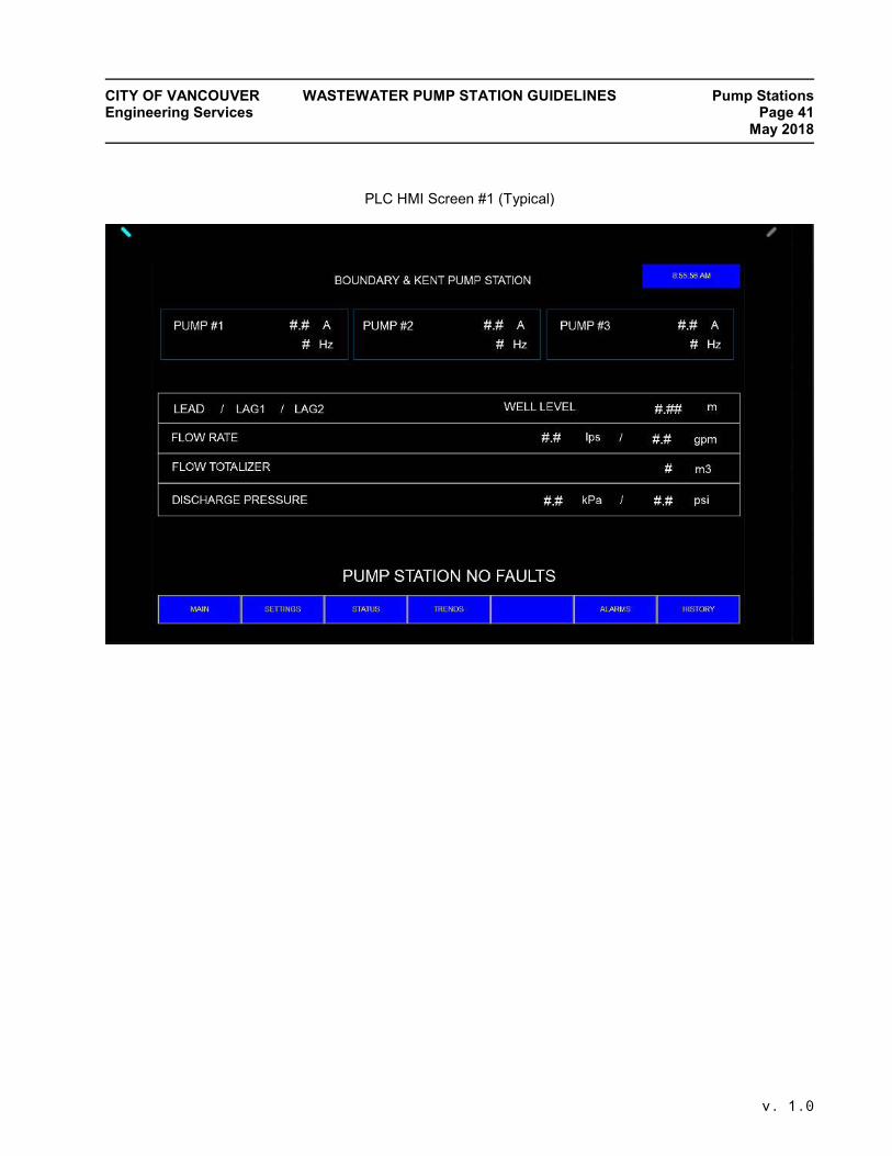
CITY OF VANCOUVER WASTEWATER PUMP STATION GUIDELINES Pump Stations Engineering Services Page 41 May 2018
v. 1.0
PLC HMI Screen #1 (Typical)

CITY OF VANCOUVER WASTEWATER PUMP STATION GUIDELINES Pump Stations Engineering Services Page 42 May 2018
v. 1.0
PLC HMI Screen #2 (Typical)

CITY OF VANCOUVER WASTEWATER PUMP STATION GUIDELINES Pump Stations Engineering Services Page 43 May 2018
v. 1.0
PLC HMI Screen #3 (Typical)
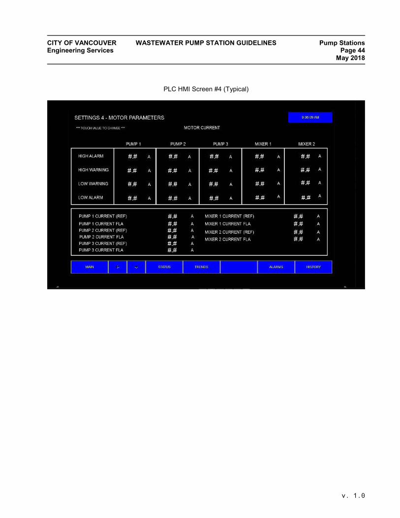
CITY OF VANCOUVER WASTEWATER PUMP STATION GUIDELINES Pump Stations Engineering Services Page 44 May 2018
v. 1.0
PLC HMI Screen #4 (Typical)
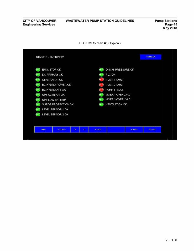
CITY OF VANCOUVER WASTEWATER PUMP STATION GUIDELINES Pump Stations Engineering Services Page 45 May 2018
v. 1.0
PLC HMI Screen #5 (Typical)

CITY OF VANCOUVER WASTEWATER PUMP STATION GUIDELINES Pump Stations Engineering Services Page 46 May 2018
v. 1.0
PLC HMI Screen #6 (Typical)

CITY OF VANCOUVER WASTEWATER PUMP STATION GUIDELINES Pump Stations Engineering Services Page 47 May 2018
v. 1.0
PLC HMI Screen #7 (Typical)
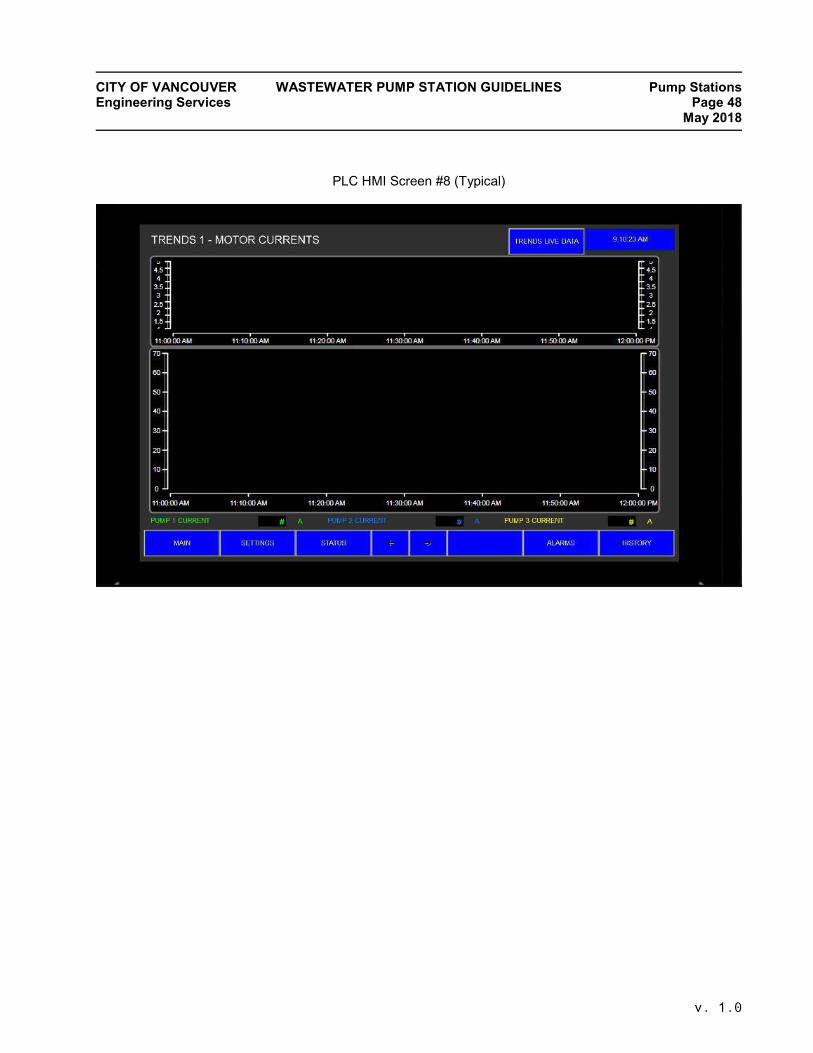
CITY OF VANCOUVER WASTEWATER PUMP STATION GUIDELINES Pump Stations Engineering Services Page 48 May 2018
v. 1.0
PLC HMI Screen #8 (Typical)


