Waste Minimiztion in the Foundry Industry - InfoHouseinfohouse.p2ric.org/ref/39/38459.pdf · WASTE...
20
WASTE MANAGEMENT^^' P 04897 HAZARDOUS WASTE MINIMIZATION: PART VI Waste Minimization in the Foundry Industry Daniel E. Oman RMT, Inc. Madison, Wisconsin ~ ~~~ ~ ~~~~~~~ ~- ~~ ~ Be foundry industry is a major consumer of waste materials (scrap). Udortunately, the recycling of these waste materials can result in the generation o f hazardous wastes that must be properly managed at a significant cost. Tdis article focuses on two waste streams in the foundry industry; calcium carbide desulfurization slag and melt emission control residuals. The author presents an overview of how foundries have evaluated different waste management options with the ultimate goal of "izi. the generation o f hazardous waste. Although there may be differences in certain operations, basic foundry pro- cesses vary only slightly from one foundry to another. All foundry opera- tions produce castings by pouring mol- ten metal into molds, often consisting of molding sand and core sand. Once the casting has hardened, it is separat- ed from the molding and core materials in the shakeout process. The castings are cleaned, inspected, and then shipped for delivery. Figure 1 is a sche- matic of a typical foundry process, showing both finished product and the types of air emissions and wastes gen- erated.' Foundries are major consumers of waste materials. Scrap iron and steel are a major source of raw materials, amounting to 85 percent or more of the ten million tons of ferrous castings pro- duced annually. Reclaimed copper, aluminum, lead, tin, zinc, and other metals are also recycled to a major ex- tent in making castings. The recycled cast product is evident everywhere in the artifads and machines which con- stitute man's material civilization. In addition, other residues from manufac- turing operations, such as asphalts, pitches, sugars, resins, and cellulose - Gpyright 1988-AFCA waste, are reused in the foundry pro- cesses. Foundry Wastes Foundry Solid Waste An overall materials balance for a foundry is shown in Figure 2. Metal for melting and core and mold materials are the major input streams, while product and waste core and mold mate- rials make up most of the output. Many foundries employ internal recycling of core and mold materials; however, these materials eventually lose their basic characteristics and are no longer suitable for use in the manufacturing process. They are then disposed in a landfill. Nonferrous foundries perform additional internal recycling because slags, dross and grinding residues may contain metal of sufficient value to be extracted in smelters. The reclaimed med is then returned to the foundry as an ingot, thereby reducing metal loss. Hazardous Waste Certain foundry processes have the potential to generate hazardous wastes within the plant. These processes in- clude the following: Melting-To reduce the sulfur con- tent of iron, some foundries use cal- cium carbide desulfurization in the production of ductile iron. The cal- cium carbide desulfurization slag generated by this process may ex- hibit the characteristic of reactiv- ity. Melting-Melt materials which contain significant amounts of cer- tain heavy metals-such as lead, cadmium, and chromium-may re- sult in wastes which are classified as hazardous due to EP toxicity. Molding-Nonferrous alloy cast- ings containing lead, such as cer- tain brasses and bronzes, may gen- erate system sand wastes which could be hazardous due to EP tox- icity. Core-making-Some core-making processes use strongly acidic or ba- sic substances for scrubbing the off-gases from the core-making process. Sludges from this scrub- bing process may exhibit the char- acteristic of a corrosive waste. Waste Management Options The basic management options for minimizing foundry wastes are as fol- lows: e Reducelalter product require- Alter raw materials Improve production process con- trol Recycle to the original manufactur- ing process e Recycle/beneficially reuse in other processes e Treatment menta 032' JAPCA
Transcript of Waste Minimiztion in the Foundry Industry - InfoHouseinfohouse.p2ric.org/ref/39/38459.pdf · WASTE...

WASTE MANAGEMENT^^' P 04897
HAZARDOUS WASTE MINIMIZATION: PART VI
Waste Minimization in the Foundry Industry Daniel E. Oman
RMT, Inc. Madison, Wisconsin
~ ~~~ ~ ~~~~~~~ ~- ~~ ~
B e foundry industry is a major consumer of waste materials (scrap). Udortunately, the recycling of these waste materials can result in the generation of hazardous wastes that must be properly managed at a significant cost. Tdis article focuses on two waste streams in the foundry industry; calcium carbide desulfurization slag and melt emission control residuals. The author presents an overview of how foundries have evaluated different waste management options with the ultimate goal of " i z i . the generation o f hazardous waste.
Although there may be differences in certain operations, basic foundry pro- cesses vary only slightly from one foundry to another. All foundry opera- tions produce castings by pouring mol- ten metal into molds, often consisting of molding sand and core sand. Once the casting has hardened, it is separat- ed from the molding and core materials in the shakeout process. The castings are cleaned, inspected, and then shipped for delivery. Figure 1 is a sche- matic of a typical foundry process, showing both finished product and the types of air emissions and wastes gen- erated.'
Foundries are major consumers of waste materials. Scrap iron and steel are a major source of raw materials, amounting to 85 percent or more of the ten million tons of ferrous castings pro- duced annually. Reclaimed copper, aluminum, lead, tin, zinc, and other metals are also recycled to a major ex- tent in making castings. The recycled cast product is evident everywhere in the artifads and machines which con- stitute man's material civilization. In addition, other residues from manufac- turing operations, such as asphalts, pitches, sugars, resins, and cellulose - Gpyright 1988-AFCA
waste, are reused in the foundry pro- cesses.
Foundry Wastes
Foundry Solid Waste
An overall materials balance for a foundry is shown in Figure 2. Metal for melting and core and mold materials are the major input streams, while product and waste core and mold mate- rials make up most of the output. Many foundries employ internal recycling of core and mold materials; however, these materials eventually lose their basic characteristics and are no longer suitable for use in the manufacturing process. They are then disposed in a landfill. Nonferrous foundries perform additional internal recycling because slags, dross and grinding residues may contain metal of sufficient value to be extracted in smelters. The reclaimed m e d is then returned to the foundry as an ingot, thereby reducing metal loss.
Hazardous Waste
Certain foundry processes have the potential to generate hazardous wastes
within the plant. These processes in- clude the following:
Melting-To reduce the sulfur con- tent of iron, some foundries use cal- cium carbide desulfurization in the production of ductile iron. The cal- cium carbide desulfurization slag generated by this process may ex- hibit the characteristic of reactiv- ity. Melting-Melt materials which contain significant amounts of cer- tain heavy metals-such as lead, cadmium, and chromium-may re- sult in wastes which are classified as hazardous due to EP toxicity. Molding-Nonferrous alloy cast- ings containing lead, such as cer- tain brasses and bronzes, may gen- erate system sand wastes which could be hazardous due to EP tox- icity. Core-making-Some core-making processes use strongly acidic or ba- sic substances for scrubbing the off-gases from the core-making process. Sludges from this scrub- bing process may exhibit the char- acteristic of a corrosive waste.
Waste Management Options
The basic management options for minimizing foundry wastes are as fol- lows: e Reducelalter product require-
Alter raw materials Improve production process con- trol Recycle to the original manufactur- ing process
e Recycle/beneficially reuse in other processes
e Treatment
menta
032' JAPCA


This paper wil l discuss how certain f " l r i e s have evaluated the applica- tion of these waste management op- tions for calcium carbide desulfuriza- tion slag and melt emission control re- siduals.
MAJOR MAT E R I A LS IN
Calcium Carbide Desulfurization Slag
Process Description
In the production of ductile iron, it is often necessary to add a desulfurizing agent in the melt because the charge materials contain excessive amounts of sulfur. One desulfurization agent com- monly used is solid calcium carbide (CaC,). Based on investigations by Talballa et a1.,2 the calcium carbide is thought to decompose to calcium and graphite. The calcium then reacts with sulfur in the melt to form calcium sul- fide (Cas) (Equation 1).
CaC, + 2Ca0 + 3FeS -+ 3CaS + 2CO + 3Fe (1)
The calcium carbide desulfurization slag is generally removed from the mol- ten iron in the ladle and placed into a hopper. T o ensure adequate sulfur re- moval, calcium carbide must be added in slight excess. Therefore, the slag contains both Cas and CaC2. The de- sulfurization process with calcium car- bide is shown in Figure 3.
Waste Characteristics
One common practice is to treat the calcium carbide desulfurization slag with water.3 This is done to generate and release acetylene gas from the un- reacted calcium carbide (Equation 2).
Flgum 1.
July 1988
Typical foundry ptocesses. (Source: EPA).
Volume 38, No. 7
CORE AND MOLD MATER1 ALS: SAND BINDERS ADDITIVES
-w MELT I NG MAT E RI AL S: METALLICS REFRACTORIES FUELS FLUXES - OTHER MATERIALS: GRINDING WHEELS SHOT ABRASIVE8 ETC.
FOUNDRY
INTERNAL PROCESS RECYCLING: ME TALL1 CS MOLDING SAND CORE SAND
1
Figure 2. Foundry materials balance.
MAJOR MATERIALS OUT
CASTINGS-PRODUCT SOLD
SOLID WASTE TO LANDFILL
USED CORE AND MOLDING SAND: SWEEPINGS, CORE BUTTS
MELTING WASTE: SLAG, REFRACTORIES FLUX, SCRUBBERS
DUST COLLECTOR: PARTICULATES, ABRASIVES, SHOT, ETC.
CaC, + 2H,O - Ca(OH), + C,H, (2) The other major reaction product is solid calcium hydroxide or lime.
Because this reaction is exothermic, a considerable amount of heat can be generated, which is particularly evi- dent when only small quantities of treatment water are used. Under these conditions, acetylene can ignite during the wetting and mixing of the slag. Fur- thermore, upward convection currents and steam generation resulting from treatment reactions may cause the re- lease of considerable amounts of fugi- tive dust.
NON-SOLID WASTES:
WATER I 0 COMBUSTION GASES,
The calcium sulfide in the slag may release sulfide into solution in the treatment process water. This sulfide will remain in solution a t high pH. However, in the neutral to acidic pH range, bisulfide (HS-) is converted to hydrogen sulfide gas (Equation 3).
HS- + H+ -H,S(g) p k = 7 (3)
During typical treatment operations, the alkaline nature of the calcium car- bide desulfurization slag preventa the pH from dropping to a point where hy- drogen sulfide gas is formed. However, the treatment water contains bisulfide, and therefore has the potential for re- leasing HzS if the wastewater is neu- tralized in a settling pond or wastewa- ter treatment plant before the sulfide has been adequately diluted.
Calcium carbide desulfurization slag has a distinctive odor. Since pure acet- ylene is odorless, the odor must be pro- duced by other trace constituents in the off-gases. A calcium carbide desul- furization slag sample from one ductile foundry was treated with water at a 1:l solid-to-liquid ratio and the gas collect- ed in a Tedlar bag for analysis by GC- MS. Several trace gases were identi- fied:
Arsine Divinyl sulfide (CHyCH)zS Ethanethiol (ethyl mercaptan) Methane Phosphine Carbon monoxide
The sum of measured volumes of these gases represented less than 1 per- cent of the total gas volume generated. However, the solubility of these gases in the reaction water was not accounted for. Any one of these gases (except
,
933

e
\

WASTE MA NAGEMEN T
I
?
C A L C I U M C A R B I D E
I N J E C T I O N
M o L T E N +vZ---- M E T A L L A D L E
I 4 [=I I
D E S U L F U R I 2 A T I O N S L A G
TREATMENT&- - W A T E R
W A T E R - i A T M E N T
S L A G
Figure 3. Process flow diagram.
methane and carbon monoxide), or a combination of them, could contribute to the observed odor. Furthermore, the reaction of the slag with water may give -- rise to potential health hazards if work- ers are exposed to excessive concentra- tions of these gases.
Field measurements were conducted a t a foundry site where calcium carbide desulfurization slag was being treated with water. Arsine and/or phosphine and carbon monoxide were detected with Draeger gas detection tubes; and divinyl sulfide was identified by GC- MS from a grab sample in a gas sam- pling bottle. It is difficult to differenti- ate between arsine and phosphine us- ing Draeger tubes. Sampling and analysis of off-gases using NIOSH methods P & CAM 265 and 216 showed that these substances, if present, were below the detection limits of these methods.
All three gases are of particular con- cern for human health reasons. The TLV (8-hour average) for carbon mon- oxide is 5.5 mg/m3, and the National Ambient Ai r Qual i ty S t a n d a r d (NAAQS) is 10 mg/m3. No standard for divinyl sulfide has been established in the United States. However, in the So- viet Union, where toxicological re- search on laboratory animals indicates that divinyl sulfide is a central nervous system depressant: a maximum al- lowable concentration (MAC) of 0.2 mg/m3 has been re~ommended.~
Regulatory Framework
Solid wastes can be classified as haz- ardous under the federal Resource Conservation a n d Recovery Act (RCRA) as either “listed” or “charac- teristic” wastes. One of the characteris- tics of a hazardous waste, as defined under 40 CFR 261.23, is reactivity. Cal- cium carbide desulfurization slag gen- erated a$ ductile iron foundries may be
considered hazardous by this defini- tion. Specifically, the calcium carbide slag reacts with water to form acetylene gas which may give rise to explosive mixtures a s def ined i n 40 C F R 261.23(3). Also, with a neutral to acidic pH value, the calcium carbide desul- furization slag may emit hydrogen sul- fide gas, which may result in its defini- tion as hazardous under 40 CFR 261.23 (5). Other gases, which are potentially toxic a t high concentrations, may also be generated during treatment of the slag (40 CFR 261.23 (4)). For these rea- sons, analysis and treatment of this type of waste is of great concern to the ductile iron foundry industry.
The ductile iron foundry industry has performed substantial studies and completed development work on each of the previously mentioned waste management options. A discussion of the results of that work follows.
Reduce/Alter Product Requirements
Like most specifications for prod- ucts, the requirements for ductile iron have been developed with time and ex- perience. The key property that differ- entiates grey iron from ductile iron is the sulfur content. There is a large body of information that relates the sulfur content of cast iron to the physi- cal properties. Individual manufactur- ers of products have also researched the properties needed for their prod- ucts, and have established specifica- tions for sulfur content and other relat- ed properties so that product require- ments are met.
However, often the material specifi- cations for products have been estab- lished not on the needs for the product but on what the state-of-the-art tech- nology is capable of producing. When this happens, a particular technology is actually being prescribed in a left- handed sort of way.
Some companies have found that they need to go back to square one and reassess the needs of the product to determine whether, for example, the sulfur content they have specified is too restrictive. Some companies have found that the product requirements can be adjusted without sacrificing the utility or the durability of the product.
What does this mean for calcium car- bide defulfurization? It means that, if a higher sulfur content is acceptable, the foundry will not have to go to the far end of what the calcium carbide desul- furization treatment process will pro- duce. Instead of having to add a 20 or 30 percent excess calcium carbide to the molten metal to ensure complete desulfurization, a lower dose could be used, resulting in far less unspent calci- um carbide in the waste; therefore, the wastes may not be classified as reactive hazardous waste.
This is not a purely hypothetical op- tion, but exists in reality within the foundry industry. Not all ductile iron foundries that employ calcium carbide desulfurization generate reactive haz- ardous waste. Whether the differences are due to more or less stringent prod- uct requirements cannot be deter- mined for certain. The quality of the charge metal purchased and the design of the desulfurization process itself also affect waste characteristics. But it is clear that if large excesses of the calci- um carbide reagent are not needed, and if the desulfurizing process equipment is efficient, the resulting calcium car- bide desulfurization slag will be far less reactive, if not nonreactive.
Alter Raw Materials
Here, the ductile iron foundry indus- try has two basic options. The first is to eliminate the generation of the reactive desulfurization slag by substituting calcium carbide with some other mate- rial or materials. A few large foundry companies have made major advance- ments in new desulfurization technol- ogies over the past two years. One such process involves the use of a mixture of calcium oxide, calcium fluoride, and two other materials. Their largest oper- ating ductile foundry has completely converted to this process. The foundry reports that, not only is the product quality satisfactory, but the plant has eliminated the generation of a major problem hazardous waste, and the eco- nomics of the process are actually bet- ter than calcium carbide desulfuriza- tion. The process this company devel- oped is proprietary and will likely be patented.
A second major option is to alter the charge metal by purchasing only scrap
934 JAPCA


that contains low sulfur content in the first place. This method is commonly used by steel foundries, since the prod- ucts they manufacture and the process- es they use generally require a higher grade of scrap with lower sulfur con- tent. The purchase of high grade low sulfur scrap may or may not, however, work for production of high quality ductile iron. Even if it will work, the supply of high quality scrap varies and the economics may favor other options.
COKE
Improve Process Control
Since the unspent calcium carbide (i.e., the calcium carbide that is not used in the desulfurization process) is what causes the slag to be classified as reactive, a logical method of eliminat- ing the hazardous characteristic would be to control the process better in order
I I L - \ F / DROP &
SWEEPINGS
L-J
to completely react the calcium carbide with the sulfur in the metal.
T h e problems here are twofold. First, the amount of sulfur in the scrap metal varies widely, so the metallurgist never knows exactly what dose is need- ed to just use up the calcium carbide. The second problem is that there is some inherent inefficiency in contact- ing the sulfur with the calcium carbide, and some metallurgists contend that an overdose will always be necessary, even if one could predict stoichiometri- cally exactly how much calcium car- bide was needed to reach a desired sul- fur content.
Typically, when a foundry begins us- ing calcium carbide for desulfurization, the level of unspent calcium carbide in the slag is very high. This level de- creases with time and experience, but often not to a level low enough SO the
FLUX
STACK EMISSIONS
METAL
A I
LEGEND - METAL FLOW LINE - NON-METAL FLOW LINE
WASTE FLOW LINE --- 0 WASTE GENERATION
WASTE MATERIALS
<-> NEW MATERIALS
/ / INTERMEDIATE PROOKl
Flgure 4. Foundry melt process schematic.
I
waste could be considered nonreactive. Recent innovation in process control for calcium carbide defulfurization in- clude methods of introducing the ma- terial as well as forms of the material itself. The most common form of calci- um carbide used is coarse granules. Some companies have experimented with very fine granules, coated gran- ules, and solid rods made of calcium carbide in an effort to control the phys- ics of the reaction more closely. Be- cause there is no established EPA test procedure for some of the reactivity criteria that come into play with this waste, it is hard to claim clear success, but a t least two calcium carbide manu- facturers appear to have come up with important developments for this basic option.
Recycle to the Orlginal Manufacturing Process
Often, calcium carbide desulfuriza- tion slag will contain from 10 percent to 50 percent metal. Because the slagging operations involve raking molten mate- rials off a ladle of 3,000”F metal, it is common to find fairly high metal con- tent in the slag. Sometimes, the metal comes in the form of large blocks or “pigs” of metal. Other times, it comes in the form of small granules of metal included in slag particles.
Several foundries have recognized for some time that there is a great deal of valuable material being wasted, and have sorted through desulfurization slag to reclaim chunks of metal for re- turn to the melting furnaces. Several foundries have also experimented with recharging of the entire mass of the slag back into the melting furnaces.
When this is done, the calcium hy- droxide is included in melting furnace slag, which is nonhazardous. Unspent calcium carbide is either used or oxi- dized in the melting furnace. However, little testing has been done to deter- mine where the sulfur actually goes. Most of it may be included in the slag, but i t may also be emitted to the air as sulfur dioxide, or, for foundries with wet emission control systems, it may be dissolved in the water.
Foundries which have tested this method have found that, with good control and metering of the recycle, the sulfur does not seem to concentrate in the metal, so the first hurdle-that of producing quality products-looks manageable.
Before, going forward with this op- tion, a foundry needs to know the envi- ronmental effects on all media for this recycling operation. It needs to know what additional contaminants are be- ing placed into the air, into the water,
July 1988 Volume 38, No. 7 935


WASTE MANAGEMENT
and into wastes from the process. But, given that those things are known and turn out favorable for the recycling, other major hurdles are the logistics of the recharge and regulatory con- straints.
Recycle/Beneficially Reuse in Other Processes
Because the calcium carbide desul- furization slag contains lime, some foundries have determined that it can be useful in dealing with other prob- lems that they may have. Since some foundries generate melt emission con- trol residuals (e.g., furnace dust) that are classified as EP-toxic due to lead and cadmium leaching, they have found that by blending calcium carbide desulfurization slag with the melt emission control residuals in proper doses, the mixture is often non-EP- toxic. Because the majority of this t rea tment effect is accomplished through the lime content of the slag, one must be concerned about overdos- ing, since raising the pH of the furnace dust too high (above about pH 11.0) will cause lead to leach out. (Lead leaches a t both low and high pHs.) RMT has experimented with treat- ment substances that, when mixed with calcium carbide desulfurization slag, will cause melt emission control residuals to be rendered non-EP-toxic, and will also ensure that the treated waste does not cause problems when disposed in a nonacidic environment.
C.
Treatment
We have seen that the state-of-the- art methods for spraying or immersing the desulfurization slag in water have the potential to cause difficult air emis- sions and industrial hygiene problems. Several foundry companies and re- search groups have evaluated three dif- ferent basic types of reactors for treat- ment of calcium carbide desulfuriza- tion slag.
The first, a reactor system involving immersion of the slag in water, is really a more controlled version of the meth- ods commonly used by foundries a t this time. The British Cast Iron Research Association has done work on these types of reactors over the past 10 years, and has developed prototypes for sys- tems to introduce the slag into the wa- ter.
Some groups experimenting with these types of processes have experi- enced problems with gas control and fires or explosions. Since the latent heat from the desulfurization slag is slow to dissipate, potentially explosive conditions can develop where the per-
I
936
sonnel operating the treatment sys- tems simply do not wait long enough to pay close enough attention to the con- dition of the slag before introducing it to the treatment systems. The proto- type systems that have been suggested and tried deal with quantities of desul- furization slag, usually less than 200 pounds per batch, and require trained and knowledgeable people to operate. The foundry industry has generally shied away from water-based reactors for the desulfurization slag based on inherent problems with process control and dependency on personnel.
A second major type of reactor in- volves thermal destruction of the calci- um carbide. At about l,XO"F, both cal- cium carbide and acetylene are ther- mally oxidized. Therefore, a system such as a rotary kiln could be used for thermal destruction of the reactivity characteristics. The additional benefit of thermal destruction is that it will also effectively deal with potential sul- fide reactivity problems. Large chunks of metals often included in the desul- furization slag will tend to be a problem for many types of thermal units. Con- cern over air emissions and cost are other hurdles to the use of thermal sys- tems for calcium carbide desulfuriza- tion slag.
Some efforts have been made to use the latent heat of the slag (the slag gen- erally runs from 2,600 to 2,900'F when it is generated) by introducing a small flow of oxygen into the very hot slag. Little serious exerimentation has been done for this method, since the system again involves a process that is differ- 'ent than what has been used in the past
and would appear to be personnel-de- pendent.
A third treatment method involves chemical reaction of the calcium car- bide, the acetylene, the other potential off-gases, and the sulfide through use of strong oxidizing agents, such as po- tassium permanganate and hydrogen peroxide. These chemicals have been shown to be effective in reducing off- gases and in eliminating sulfide reac- tivity when introduced to the water that is used to treat the slag. However, the chemical doses for achieving all of those goals are very high, and full-scale systems would be very costly.
Improve Existing Treatment Methods
Some improvements that have been made to the crude methods normally used by foundries to treat reactive cal- cium carbide desulfurization slag in- clude treatment of the waste in a tank rather than in a waste pile. The tanks, generally constructed with three verti- cal sides and a ramped floor on the fourth side, first involved placing the waste and spraying water into it. Later versions have involved deeper tanks with flat floors that will allow placing hoppers of slag in the bottom of the tanks and immersing them in water by a combination of spraying and flood- ing. Experiments have shown that, if the slag can be rapidly covered by wa- ter, as little as one foot of water over the top of the slag will act as a scrubber; and many of the gases, including acety- lene, arsine, and phosphine, will largely be dissolved in the water. When chemi- cal oxidants such as potassium per-
15
12
i 2 7 8 9 10 11 12 13 14 15
TIME (DAYS)
Figure 5. Fandry charge modification EP toxicity test results.
JAPCA

C. .
\
manganate or hydrogen peroxide are added to the water, the air pollution control effectiveness seems to increase.
However, the foundry must be con- cerned about dissolving large quanti- ties of flammable and toxic gases as well as sulfides, since introducing this water to the plant’s wastewater treat- ment system or to the sanitary sewer could cause the gases to be liberated again at some other point.
Also, there is serious question as to whether such a system would be capa- ble of obtaining a RCRA Part B Permit to operate without formal air emission control systems. These open tank sys- tems are designed to be crude but effec- tive. When one begins to try to collect flammable and toxic gases over such open tanks and to allow access of fork lift trucks to deliver and retrieve hop- pers of slag, the logic of the system falls apart very quickly and one returns to the reactor concept or other options.
Summary of Options
The best options for calcium carbide desulfurization slag management ap- pear to lie in altering the raw materials, improving the process control, and re- cycling to the original manufacturing processes, assuming the product re- quirements cannot be modified enough to eliminate the generation of reactive desulfurization slag using calcium car- bide. Several foundries and suppliers have made major advancements in each of these options, and the next two or three years will tell which of the op- tions becomes most popular.
C.
Melt Emission Control Residuals
Process Description
The production of iron castings re- quires that the metal be in a molten state so that it can be poured into the open cavity of the mold to produce the desired shape of the casting. Foundries which produce grey iron castings use one of the following three different pro- cesses to melt the grey iron: 0 Cupola
Electric arc furnace Induction furnace
The Clean Air Act set standards for the discharge of emissions into the at- mosphere. Many foundries have been required to install air pollution control equipment over their melting opera- tions to come into compliance with these regulations. Foundries typically use either a dry baghouse or some form of wet scrubber system (e.g., wet cap,
July 1988 Volume 38, No. 7
venturi, etc.) to collect the particulates for the melting operation.
A materials flow diagram for the melting operation within a typical foundry (with cupola melting) is illus- trated in Figure 4. As illustrated in this figure, new materials into the melting operation include scrap metal, fluxes, coke (source of fuel for the cupola), and refractory material. Outgoing wastes generated by the process include spent refractories, slag, bottom drop and sweepings (for cupola operations), and either baghouse dust or a wet sludge depending on the type of emission con- trol system. Typical pouring tempera- tures for grey irons range anywhere from 2,040’F to 2,700’F.
Waste Characteristics
Of all the waste generated by this process, the one that has been shown to be hazardous in some cases is the emis- sion control residuals collected by the air pollution equipment. Whether or not the emission control residual is hazardous is largely a function of the incoming quality of the metal which is charged into the furnace. The inflow of tramp metals into the furnace from other new materials, such as coke or flux, is generally small in comparison to the contribution of such metals from t h e incoming scrap. N u m e r o u s “tramp” metals or minor constituent metals contained in the scrap which is charged into the furnace include cop- per, nickel, chromium, molybdenum, tin, aluminum, and lead. In general, the higher grades of scrap exhibit lower concentrations of these metals, while the lower grades of scrap exhibit higher concentrations of the tramp metals.
T
. m 5 0.9
z 1 0.4 z
0.2
0.1
What grade of scrap is used by a given foundry islargely dictated by the quali- ty of the casting being produced. For example, foundries which are produc- ing counterweights for heavy machin- ery tend to use a much lower grade scrap than those foundries which are producing high grade industrial cast iron valves.
The reason the emission control re- siduals have sometimes exceeded EP toxicity hazardous waste limits for lead is because the melting point of grey iron is approximately 2,700°F, where the melting point for lead is only about 620’F. As the metal is melted, the lead will tend to volatilize and concentrate in the residual solid materials collected by either the baghouse or wet dust col- lection emission control system.
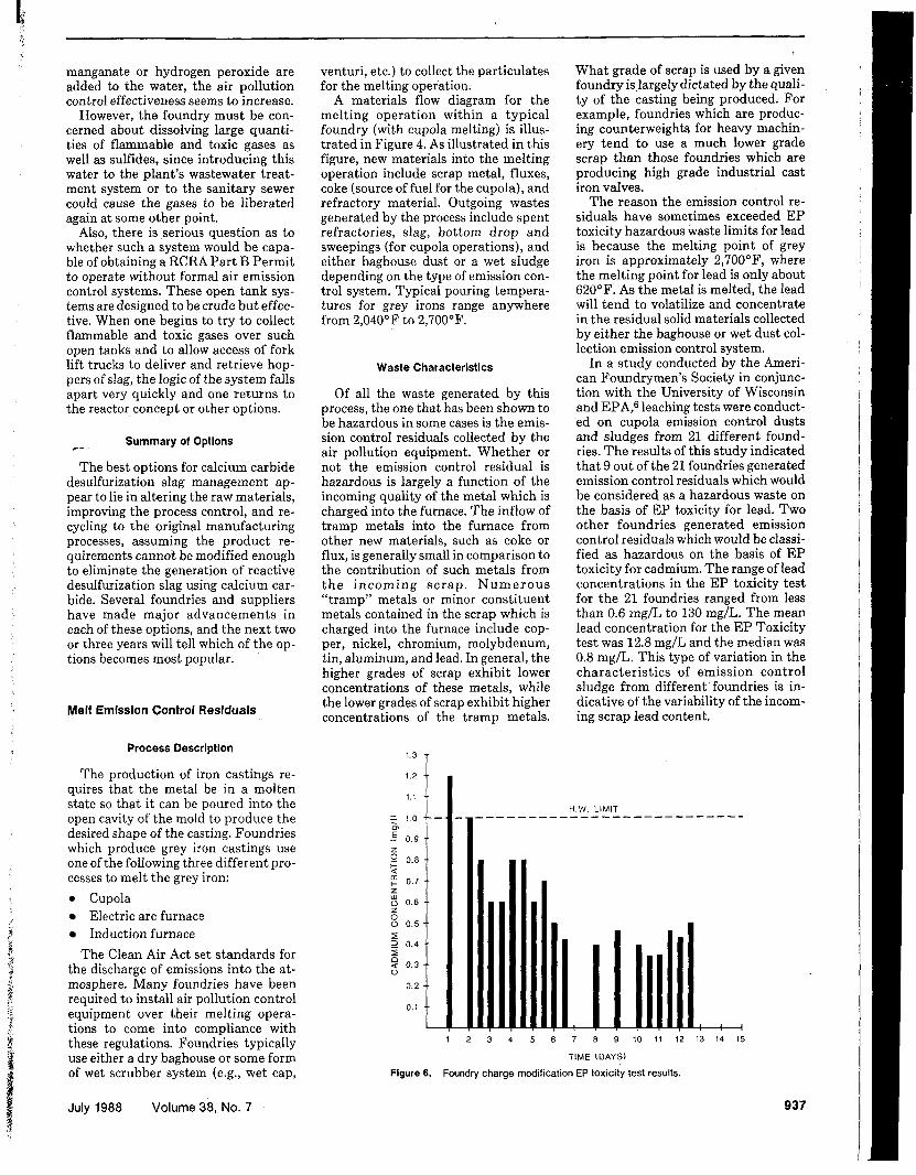
In a study conducted by the Ameri- can Foundrymen’s Society ir, conjunc- tion with the University of Wisconsin and EPA,G leaching tests were conduct- ed on cupola emission control dusts and sludges from 21 different found- ries. The results of this study indicated that 9 out of the 21 foundries generated emission control residuals which would be considered as a hazardous waste on the basis of EP toxicity for lead. TWO other foundries generated emission control residuals which would be classi- fied as hazardous on the basis of EP toxicity for cadmium. The range of lead concentrations in the EP toxicity test for the 21 foundries ranged from less than 0.6 mg/L to 130 mg/L. The mean lead concentration for the EP Toxicity test was 12.8 mg/L and the median was 0.8 mg/L. This type of variation in the characteristics of emission control sludge from different foundries is in- dicative of the variability of the incom- ing scrap lead content.
H.W LIMIT
1 2 3 4 5 6 7 8 9 1 0 1 1 1 2 1 3 1 4 1 5
TIME (DAYS)
Figure 6. Foundry charge modification EP toxicity test results.
937


WASTE MANAGEMENT
cn E - v) 3 2 5 3 In W U ; 15 W t- n w 5
LEAD H.W. LIMIT ----- I CADMIUM H.W. LIMIT -
BLANK +5% +7.5%
DOSAGE ( X IRON FILINGS)
Flgure 7. control sludge treated with metallic iron.
Lead and cadmium leachate concentrations from cupola emission
Regulatory Framework
At this time, EPA has not “listed” emission control residuals from grey
~. iron foundries as hazardous. It is un- likely that these wastes meet the char- acteristic of ignitability, corrosivity, or reactivity. However, it has been dem- onstrated in previous research that certain foundries do generate emission control residuals which meet the char- acteristics of E P toxicity. Those wastes which are classified as a haz- ardous waste on the basis of the EP toxicity criteria, must be managed ac- cording to the hazardous waste man- agement regulations promulgated un- der RCRA.
Reduce/Alter Product Requirements
The key issue in reducing or altering product requirements relative to mini- mizing the generation of EP-toxic emission control residuals is that the chief source of contamination, namely lead and/or cadmium, is not required in the production of grey iron. These materials are in fact “tramp metals” that are present in the scrap materials which are being recycled by the found- ry industry to produce their castings. In fact, elevated levels of lead in grey iron can cause negative structural af- fects on the cast iron. Therefore, while it would be fundamentally sound to at- tempt to reduce or alter lead content product requirements, in reality, lead is not even required for casting produc- tion. Therefore, this management op- tion has little usefulness in the minimi- zation of waste generation.
I
Alter Raw Materials
A predominant source of lead that is contained in the emission control re- siduals from foundry melting opera-
i tions, is contained within the scrap ma- t
terial itself. It is true that other new materials such as coke and certain flux- es may also be sources of incoming lead. However, generally these sources con- tain much lower quantities of lead than does the incoming scrap.
The first step in altering raw materi- als to successfully minimize the genera- tion of hazardous wastes from emission control residuals, is to identify the in- coming source or sources of lead and cadmium. Although the incoming scrap is generally the primary source of lead, all incoming sources should be evaluated on a preliminary basis to ver- ify this assumption. It has been the authors’s experience that, in some cases, even the soil that has adhered to the scrap coming from the scrap yard may be a source of lead. In one case, this soil material was subjected to the EP toxicity test by the author and found to exceed the hazardous waste criterion for lead in the EP toxicity test. To eliminate this source, the foundry in question placed pallets a t the base of the charge bins and had to
manually clean incoming loads of dirty scrap to eliminate this contamination source.
Once the sources of lead have been identified, the next basic step is to make purchasing arrangements to ac- quire alternative sources of new mate- rials which contain lower concentra- tions of lead and cadmium. Once these sources have been obtained, a charge modification program is developed and implemented using the new sources of raw materials. It is advisable to first purge the emission control system of residual waste material prior to imple- menting the charge modification pro- gram. In general, carryover from exist- ing waste in the emission control sys- tem can mask the true results of the charge modification program unless proper precautions have been taken to purge the system.
Figure 5 and Figure 6 illustrate a re- duction in lead and cadmium concen- trations from the EP toxicity test on emission control residuals collected during a two-week charge modification program a t a large foundry. In Figure 5, a drastic reduction in lead concentra- tion with time can be seen over the first two or three days of the charge modifi- cation program. This is typical of other charge modification programs which have been conducted, assuming ade- quate purging of the system has been performed prior to the charge modifi- cation program. According to Figure 6, the reduction in cadmium concentra- tion with time does not show the same drastic reduction experienced with lead. However, the charge modification program for this foundry was also SUC- cessful in reducing cadmium levels to below the hazardous waste limit in the EP toxicity test.
Altering raw materials has been
- h
OI
- . E 3 5 - - z I-
2 2 5 I- z Y - o 5 15
- o 0 4
0 - - - -
BLANK 15% LIME 2 0 % LIME 10% Mg(OH),
DOSAGE
0 EP TOXICITY TEST - LEAD H.W. LIMIT = WATER LEACH TEST
Figure 8. treated with lime or magnesium hydroxide.
Lead leachate concentrations from brass foundry solid waste
JAPCA 938


W 0 2 z 0 0 0
W J
4 1
a
\
\ \ AVERAGE INITIAL LEAD VALUE = 210mgl1
\ \ \ \ * \
DOSAGE (gm Mg(OH),lgm S.S)
- LEAD H . W . LIMIT Figure 9. from wastewater treated with magnesium hydroxide.
Lead leachate concentrations from cupola emission control sludge
C. shown to be a successful way to mini- mize the generation of hazardous emis- sion control residuals in the foundry industry. However, while charge modi- fication programs have been success- ful, it is generally not economical for a foundry to continue to melt the higher grade scrap and still remain competi- tive. In many cases, foundries have conducted successful charge modifica- tions only to realize that the economics of the higher grade scrap preclude its continued use in the foundry; there- fore, the charge modification program is abandoned.
Improved Process Control
The reason hazardous wastes are sometimes generated by the foundry industry is because airborne particu- lates, which prior to the Clean Air Act would have been released to the atmo- sphere, are now required to be cap- tured through air pollution control equipment. Some foundries have cho- sen to switch to induction melting fur- naces to melt grey iron. One of the ad- vantages of the electric induction melt- ing furnace is that, in general, air pollution control equipment is not nec- essary for the emissions from this oper- ation. This assumes, however, that rel- atively clean materials, (e.g., clean met- al scrap) can be used in the melting process. Obviously, the elimination of the need for collecting emissions over the melting operation eliminates the generation of air pollution control re- siduals. When this can be done, it is an effective way to minimize waste gener- ation.
R,ecycle to the Orlginal Manufacturing Process
The recharging of the emission con- trol residuals is a common practice in the steel-making i n d ~ s t r y . ~ This has been done in some cases to supplement alloy materials which are added to the melting operation. The practice of re- charging foundry emission control re- siduals has been investigated by some foundries with varying degrees of SUC- cess. Materials handling and the metal- lurgic considerations will definitely im- pact the feasibility of such an alterna- tive. This method for hazardous waste elimination is generally not used by a majority of foundries.
Recycle/Beneficlally Reuse
Another reuse alternative would be to reclaim the lead and cadmium which
50 '2 5 a 0 8
0
July 1988 Volume 38, No. 7
have concentrated in the emissioni con- trol residuals. The feasibility of this reclamation outside of the original pro- duction process largely depends on the following: 0 Concentration of metals within the
emission control residual. Cost of recovering the metals.
0 Market price for the product.
While recycling of these materials out- side the original production process has been used in the nonferrous found- ry industry (i.e., brass foundry), its ap- plication within grey iron foundries is extremely limited.
Treatment. Various chemical means have been used to reduce the leaching potential of toxic metals. The four types of chemical treatment applicable to emission control residual waste which are EP-toxic for either lead or cadmium include the following: 0 Precipitation
Absorption 0 Chemical reduction
pHcontrol This paper will highlight two of L e
four chemical t reatment methods which have been used quite extensively in the foundry industry.
Chemical reduction. Chemical treat- ment using metallic iron added to haz- ardous wastes has proved effective. Figure 7 shows that at a dosage of 5 percent (by weight) iron filings, lead leaching from a cupola emission con- trol sludge was reduced from 28.6 mg/L to less than 0.1 mg/L8 At a dosage of 7.5 percent (by weight) iron filings did not significantly increase treatment ef- fectiveness. Cadmium leaching was vir- tually unaffected by treatment at these dosages. The mechanism proposed to explain the observed decrease in lead
T //'
a
, / * /
1 1 1 1 1 1 I I 1 1 ' 1 8.0 I I " 8.5 7.0 7.5
FINAL pH IN EP TEST
Flgure 10. Percent reduction in cadmium leachate concentration vs. final pH in EP toxicity tests on cupola emission control sludge from wastewater treated with magnesium hydroxide.
939
I
I
I ,


!VAST€ MANAGEMENT
c.
leaching is a redox reaction whereby metallic iron reduces divalent lead to metallic lead.8
Evidence for a redox mechanism is found in EP toxicity test results. The addition of iron filings resulted in a fi- nal pH in the EP toxicity test slightly higher than untreated samples, indi- cating that the hydrogen ion may have been neutralized by chemical reduc- tion.
Some success has been achieved us- ing metallic iron to treat wastewater directly. An advantage of using metal- lic iron instead of iron hydroxide is that less sludge volume is generated. The presence of oxidizing agents in the wastewater can limit the effectiveness of metallic iron treatment.
p H control of solubility. Another method of chemical treatment involves the pH of the waste so metals will not be soluble when exposed to acidic con- ditions. Since the solubility of many metals, including lead and cadmium, is pH dependent, waste classified as EP- toxic can sometimes be rendered non- hazardous by adding a material that will maintain a neutral or slightly alka- line pH during leaching with an acidic liquid, so the metals will not dissolve.
One of the simplest and most cost- effective additives for this purpose is slaked lime (Ca(0H)Z). I t is well- known that lime is effective in precipi- tating lead and cadmium as insoluble hydroxides. However, excess dosages of lime can result in pH values high enough to redissolve lead. The addition of 15 percent by weight lime to brass foundry solid waste reduced lead leach- ing from 22 m g b to <O.I mg/L (final pH in EP toxicity test of 7.8). However, when a water leaching test with no acid added was used, the pH was 11.6 and lead leached at 7.2 mg/L (Figure 8). This can pose a limitation to the use of lime because most leaching at disposal sites for treated foundry wastes is like- ly to be under leaching conditions with close to neutral pH. Similar results were presented by Nagle et aL7
Because of the problem of dissolving lead a t higher pH values, magnesium hydroxide (Mg(0H)Z) is a more desir- able material for pH control than lime.g Magnesium hydroxide is buffered a t a maximum pH of approximately 10.5; therefore, the potential for dissolving lead at higher pH is minimal even if an excess of Mg(OH)* is added. Adding 10 percent Mg(0H)z by weight as a 55 per- cent slurry to the same brass solid waste reduced lead leaching to 0.3 mgl L (final pH of 8.5 in EP toxicity test). Less than 0.1 mg/L of lead leached in the water leach test (Figure 8).
Magnesium hydroxide slurry has been‘ tested on wastewaters from three
foundry cupola emission control sys- tems. Doses ranging from 0.3 to 111 grams of Mg(0H)z per gram of sus- pended solids resulted in a reduction in lead leaching from the resulting sludge to well below the hazardous waste Iim- its (Figure 9). Reduction of cadmium leaching is dependent on the final pH of the leaching medium in the E P Tox- icity test. Data for the Mg(0H)z treat- ment tests indicate that a final pH of eight or more is required for significant reduction in cadmium leaching (Figure 10).
Although magnesium hydroxide is more expensive than lime, it is prefera- ble to lime because it has the benefit of easier pH control, thereby reducing process control requirements. The re- sults of testing show that, while in many cases adding lime or magnesium hydroxide is effective in rendering a hazardous waste nonhazardous, knowl- edge of the leaching characteristics of the waste material and the treated waste mixture is important to ensure effective treatment and proper dispos- al. Also, while pH control of solubility appears to be an effective treatment method in the short-term, long-term characteristics of the chemical additive should be evaluated to ensure that the waste will remain nonhazardous over time.
Summary of Options
The best option for emission control residual management appears to be ei- ther altering the raw materials (Le., charge modification) or the use of elec- tric induction melting without air pol- lution control equipment. When these options are not feasible from an eco- nomic standpoint, the only remaining option, other than hazardous waste dis- posal, is to treat the waste using an appropriate form of chemical treat- ment.
References
1. A. T. Kearney Company. February 1971. “Systems Analysis of Emission 7,ontrol in the Iron Foundry Industry, U.S. EPA, CPA 22-69-106, Exhibit IV, Re- printed in US . EPA Environmental As- sessment of Iron Casting, EPA-60012- 80-021, January 1980, p. 17.
2. M. Talballa, P. K. Trojan, L. 0. Brock- way, “Mechanisms of desulfurization of liauid iron carbon allov with solid CaC? an‘d CaO,” Am. Foundrymen’s Soc: Trans. 84: 775 (1976).
3. T. R. Stolzenburg, “Analysis and treat- ment of reactivewaste: a case study in the ductile iron foundry industry,” Pur- due Ind. Waste Conf. Trans. May 1985.
4. B. A. Trofimov, S. V. Amosova, “Divinyl sulfide: synthesis, properties, and appli- cations,” Sulfur Reports 3: 323 (1964).
5. I. A. Glukharev, E. R. Ushdavin, A. A. Marnaeva,V. C. Gilev, A. A. Stephanova.
1980. Substantiation of the maximum al- lowable concentration of divinyl sulfide in the air of a working zone. Gigieno Truda I Professionnlly Truda. No. 7 pp. 51-52.
6. W. C. Boyle, R. K. Ham, J. Pastene, R. Stanforth, “Leachate tests on selected foundry cupola dusts and sludges,” Am. Foundrymen’s SOC. Trans. 89: 767 (1981).
7. D. L. Nagle, R. R. Stanforth, P. E. Duran- ceau, T. P. Kunes, “Treatment of hazard- ous foundry melting furnace dust and sludges,” Am. Foundrymen’s SOC. Trans. 91: 715 (1983).
6. W. A. Stephens, T. R. Stolzenbur , R R. Stanforth, J. E. Etzel, “Use of fron to Render Sludge from Ferrous Foundry Melting Furnace Emission Control Waste Nonhazardous,” presented at the 39th Annual Purdue Industrial Waste Conference, West Lafayette, IN, May 1984.
9. P. D. Turpin, et al. “Methods to treat EP-toxic foundry wastes and waste- waters,” Am. Foundrymen’s SOC. Trans. 93: 737 (1985).
I Daniel E. Oman, P.E., is manager
of engineering, a t RMT, Inc., Suite 124,1406 East Washington Avenue, Madison, WI 53707. This paper was submitted for peer review April 28, 1988; the revised manuscript was re- ceived June 1,1988.
940 JAPCA

C. .

PUBLISHER Martin E. Rivers Executive Vice President
EDITORIAL STAFF Harold M. Englund Editor Leonard F. Mafrica Associate Editor James D. Morton Production Coordinator Barbara A. Yunk Editorial Assistant
EDITORIAL REVIEW BOARD Chairman Paul J. Lioy
Robert Wood Johnson Medical School, UMDNJ
Vice Chairman Chester W. Spicer
Secretary George T. Wolff
-A Larry Anderson
Battelle Memorial Institute
General Motors Research Labs
University of Colorado at Denver Walter C. Barber
Chemical Waste Management, Inc. Eileen Brennan
Rutgers University Yoram Cohen
University of California, Los Angeles Mackenzie L. Davis
Michigan State University Thomas R. Hauser
U.S. Environmental Protection Agency Gale Hoffhagle
TRC Environmental Consultants John A. Jaksch
U.S. Environmental Protection Agency R. K. M. Jayanty
Research Triangle Institute Ralph I. Larsen
U.S. Environmental Protection Agency Michael D. Lebowitz
University of Arizona Charles G. Noll
United McGill Corporation William R. Pierson
Desert Research Institute Perry J. Samson
University of Michigan
BUSINESS STAFF Daniel R. Steam Advertising Sales Manager
Lynn K. Sullivan Marketing Liaison Assistant P.O. Box 2861 Pittsburgh, PA 15230 (412) 232-34-44
A Monthly Journal Devoted to
Air Quality and Waste Management 0 Copyright 1988
APCA Printed in the United States
JULY 1988 VOLUME 38 NUMBER 7
The International Journal of Air Pollution Control and Waste Management
Health Significance of Pulmonary Function Res nses to Airborne h i tan ts Ex sues to airborne irritants can produce measurable cgnges in a variety of pulmonary
Gctions. M. Lippmann
PM-10 Implementation of Standards. A Summary of the APCA/EPA
A summary of the complete technical program, grouped according to technical content.
The Scientific and Technical Issues Facing Post-1987 Ozone Control
Summarizes technical presentations given at an APCA international specialty conference
International Specialty Conference C. V. Mathai, D. H. Stonefield, J. G. Watson, Jr.
Strategies: A Conference Summary
on tropospheric ozone and ozone control strategies. G. T. Wolff, J. L. Hanisch, K. L. Schere, R. Cahaly
* * * *
Carbon Monoxide in an Urban Environment: Application of a Receptor Model for Source Apportionment
M. A. X. Khalil, R. A. Rasmussen
G. B. Howe, R. K. M. Jayanty,%. Jackson, C. E. Riley, G. D. McAlister
R. L. Fleischer
Evaluation of Method 25 Nonmethane Or anic Analyzer Design
Basement Ventilation Needed to Lower Indoor Radon to Acceptable Levels
The Impact of Migration on Air Quality Dose-Response Functions: A Case Study of Jacksonville, Florida
G. Erfani, F. W. Bell
An Evaluation of the Effects of Ozone In'ury on Radial Growth of
D. L. Peterson, M. J. Arbaugh Ponderosa Pine (Pinusponderosa) in t i e Southern Sierra Nevada
APCA NOTE-BOOK California Statewide Assessment of the Effects of Ozone on Crop
Productivity D. M. Olszyk, H. Cabrera, C. R. Thompson
WASTE MANAGEMENT Hazardous Waste Minimization: Part VI. Waste Minimization in the
An overview of how foundries have evaluated different waste management options, toward Foundry Industry
the goal of minimizing waste generation. D. E. Oman
A Model Analysis of Metal Partitioning in a Hazardous Waste Incineration System
C. C. Lee
CONTROL TECHNOLOGY Use of Seawater in Flue Gas Desulfurization: A New Low-Cost FGD
System for Special A plications J. g, Abrams, S. J. Zaczek, A. D. Benz, L. Awerbuch, J. Haidinger
DEPARTMENTS APCA News ....................... ,956 Index to Advertisers Business Briefs ..................... .951 Calendar .......................... ,955 Calls For Papers .................... ,978 Classified .......................... .977 The Computer Comer . . . . . . . . . . . . . . . .874 Control Technology Newsbriefs ...... ,975 Current Literature . . . . . . . . . . . . . . . . . . ,957 Debut ............................. .961 IGCI Newsletter .................... .878
881
888
895
901
907
914
917
921
928
932
941
969
. . . .980 Institutional Notes . . . . . . . . . . . . . . . . . . ,952 Legal Briefs ........................ ,979 Microcomputer Software Reviews . . . . ,948 NewsFocus ......................... 950 Personalia .......................... 953 Professional Development Programs . . ,976 Professional Services Directory . . . . . . . ,963 Washington Report . . . . . . . . . . . . . . . . . ,872 Waste Management News . . . . . . . . . . . . .876
870 JAPCA