Waste Heat Recovery · PDF file... Water tube, co-flow (concurrent flue-gas flows) ... Safety...
14
WASTE HEAT RECOVERY SYSTEMS Transparent Energy Systems Pvt. Ltd. Pune- 37. (INDIA) Tel : 020 – 24211347, Fax : 020 – 24212533. E-mail : [email protected] & [email protected]
Transcript of Waste Heat Recovery · PDF file... Water tube, co-flow (concurrent flue-gas flows) ... Safety...

WASTE HEAT RECOVERY SYSTEMS
Transparent Energy Systems Pvt. Ltd.Pune- 37. (INDIA)Tel : 020 – 24211347, Fax : 020 – 24212533.E-mail : [email protected] & [email protected]
Transparent has developed wide variety of superefficient Heat Recovery Systems forharnessing all types of waste heat, originating from various fuels and from different industrialsources.
The Waste Heat Recovery Boilers are provided with Economizers which improve their thermaloutput and efficiency.
Transparent superefficient Waste Heat Recovery Systems find ideal applications in CogenerationSystems working on Reciprocating Engines and Gas Turbines.
Converting into useful formEnergy is consumed in various forms like steam, hot water, Chilling, refrigeration etc. at differentplaces. Please refer next page for separate matrix to check different useful forms of energy to whichthis waste heat can be converted. Transparent has expertise in converting this waste energyinto the most beneficial form of energy for any customer.
Various models of heat recovery systemsTransparent has developed following wide range of ‘application specific designs andconstructions’ of Waste Heat Recovery systems / HRSGs for above applications.
Various designs of Waste Heat Recovery Systems are :
q Recostar – FI : Finned Water tube IBR.q Recostar – S : Smoke tube IBR.q Recostar – WC : Bare Water tube, IBR.q Recostar – WCOF : Water tube, co-flow (concurrent flue-gas flows) IBR.q Recostar – WCRF : Water tube cross tube IBR.q Recostar – CC : Cylindrical coil type once through.q Recostar – PC : Pancake coil type once through.q Recostar – SCMP : Smoke tube, composite unfired plus fired type.q Recostar – JW : Engine jacket water heat recovery system
INTRODUCTION
Various sources of waste heat.
Ø Exhaust heat recovery from Reciprocating Engine driven Gen-sets used for Captive Power Cogeneration and Independent Power Production.
- Heavy fuel fired- Gas fired- Diesel fired
Ø Exhaust heat recovery from Gas Turbine exhaust. Ø Jacket heat recovery from EngineØ Hot Waste Gases from
- Scrap melting steel furnaces - Cement kilns - Industrial furnaces- Incinerators- Process Waste Gases
v Type : Finned, Water Tube, IBR
v Installation : Horizontal & Vertical, Indoor as well as Outdoor
v Tube Orientation : Horizontal & Vertical
v Waste Gas Flow Direction : Horizontal/ Vertical (Upwards & Downwards)
v Quality of Waste Gases : Normally clean dust free gases
v Acceptable dust in waste gases
: Moderate dust level acceptable for Boilers having vertical finorientation with mechanized soot removal and collecting facility.
v Type of output : Steam- D&S/ Superheated, Hot Water, Hot Thermic Fluid
v Media of Waste Heat : Hot gases, Hot bulk powders, hot liquids, hot vapours.
v Waste Heat Source suitability
: Fuel cell exhaust, micro gas turbine exhaust, DG set exhaustprocess waste gases, Incinerator exhaust, furnace exhaust.
v Typical applications : Process heating, hot water generation, Thermic Fluid heating,Power generation, Cogeneration applications.
v Number of heat recovery stages possible
: 3 to 4 stages of heat recovery possible e.g. super-heaterevaporator, economizer, water preheater
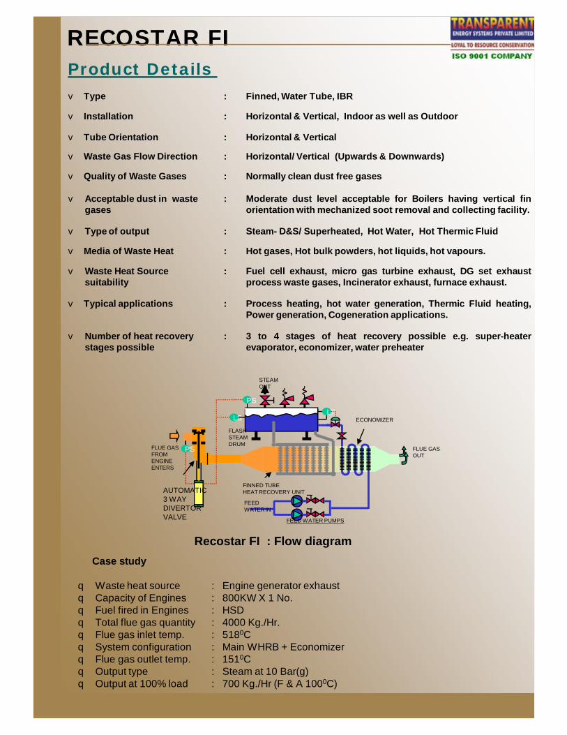
RECOSTAR FIProduct Details
FLUE GASOUT
FEED WATER IN
FEED WATER PUMPS
STEAMOUT
ECONOMIZER
FLUE GASFROM ENGINEENTERS
AUTOMATIC3 WAYDIVERTORVALVE
FLASHSTEAMDRUM
FINNED TUBEHEAT RECOVERY UNIT
LT
PS
PS
LS
Recostar FI : Flow diagramCase study
q Waste heat source : Engine generator exhaustq Capacity of Engines : 800KW X 1 No.q Fuel fired in Engines : HSDq Total flue gas quantity : 4000 Kg./Hr.q Flue gas inlet temp. : 5180Cq System configuration : Main WHRB + Economizerq Flue gas outlet temp. : 1510Cq Output type : Steam at 10 Bar(g) q Output at 100% load : 700 Kg./Hr (F & A 1000C)
v Type : Smoke Tube IBR
v Installation : Horizontal & Vertical, Indoor as well as Outdoor.
v Tube Orientation : Horizontal / Vertical.
v Waste gas flow direction : Horizontal / Vertical(upwards & downwards)
v Quality of Waste Gases : Low dust level acceptable.
v Type of heat recovery output : 1) D & S / superheated2) Hot Water3) Vapour phase Thermic Fluid Heating
v Media of Waste Heat : Hot gases, hot liquids, hot vapors
v Waste heat source suitability
: Fuel cell exhaust, Micro / miniturbine exhaust small gas turbineexhaust, DG set exhaust, process waste gases, Incineratorexhaust, furnace exhaust.
v Typical applications : Exhaust of steel furnaces, cement kilns, metal smelters,Incinerators, Industrial furnaces, DG set exhaust, process wastegases, Incinerator exhaust, furnace exhaust, Gas turbineexhaust.
v Output capacity possibilities : Typically 15 TPH
v Number of heat recovery stages possible
: 3 to 4 stages of heat recovery possible e.g. super-heater,evaporator, economizer, water preheater.
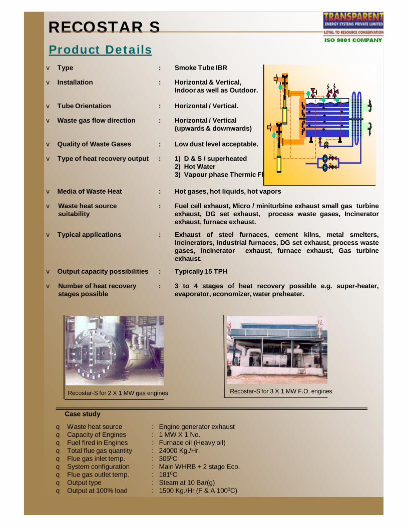
RECOSTAR SProduct Details
LT
PS
PS
LS
PS
Recostar-S for 3 X 1 MW F.O. enginesRecostar-S for 2 X 1 MW gas engines
Case study
q Waste heat source : Engine generator exhaustq Capacity of Engines : 1 MW X 1 No.q Fuel fired in Engines : Furnace oil (Heavy oil)q Total flue gas quantity : 24000 Kg./Hr.q Flue gas inlet temp. : 3050Cq System configuration : Main WHRB + 2 stage Eco.q Flue gas outlet temp. : 1810Cq Output type : Steam at 10 Bar(g) q Output at 100% load : 1500 Kg./Hr (F & A 1000C)
v Type : Water tube, coflow (Cocurrent gas flow) IBR
v Installation : Horizontal / Vertical, Indoor as well as Outdoor
v Tube Orientation : Vertical.
v Waste gas flow direction : Vertical
v Quality of Waste Gases : Specially suitable for dust laden gases. Provided with specialmechanized soot removal and collection system.
v Acceptable dust in waste gases : High dust level readily accepted
v Type of heat recovery output : 1) Steam– D & S/Superheated 2) Hot Water3) Hot Thermic Fluid
v Media of Waste Heat : Hot gases, Hot vapours
v Waste heat source suitability : Exhaust of steel furnaces, cement kilns, metal smelters,incinerators, industrial furnaces, DG set exhaust process wastegases, Incinerator exhaust, Furnace exhaust, gas turbine exhaust.
v Typical applications : Process heating, hot water generation, thermic fluid heating, powergeneration, cogeneration.
v Output capacity possibilities : No Limits.
v Number of heat recovery stages possible
: 3 to 4 stages of heat recovery possible e.g. super-heaterevaporator, economizer, water preheater
v Protection against sulphur corrosion on cold end side
: Provided by various means to ensure that metal temperature ismaintained above the actual incipient limit.
RECOSTAR WCOF Product Details
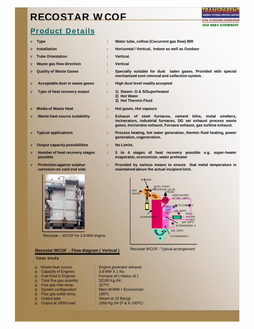
Recostar WCOF : Typical arrangement
BYPASS
AUTO. 3 WAYDIVERTOR VALVE
Steam drum
FEED WATERAT 900C
ECONOMIZER -I
EVAPORATOR
TO CHIMNEY
FEED WATERAT 180 –1850 C
STEAMHOTGAS IN
ECONOMIZER -II
155 -1600C
120 -1250C
180 -1850C
HOT GAS OUT
Recostar – WCOF for 3.8 MW engine
Case study
q Waste heat source : Engine generator exhaustq Capacity of Engines : 3.8 MW X 1 No.q Fuel fired in Engines : Furnace oil ( Heavy oil )q Total flue gas quantity : 32180 Kg./Hr.q Flue gas inlet temp. : 3270Cq System configuration : Main WHRB + Economizerq Flue gas outlet temp. : 1850Cq Output type : Steam at 10 Bar(g) q Output at 100% load : 1950 Kg./Hr (F & A 1000C)
Recostar WCOF : Flow diagram ( Vertical )

v Type : Water tube cross flow IBR
v Installation : Vertical, Indoor and Outdoor.
v Tube Orientation : Vertical.
v Waste gas flow direction : Horizontal
v Quality of Waste Gases : Moderately clean gas desired. Provided with mechanized Soot removal and collection System.
v Acceptable dust in waste gases : Moderate dust level accepted
v Type of heat recovery output : 1) Steam– D & S / Super-heater 2) Hot Water 3) Vapour phase thermic fluid
v Media of Waste Heat : Hot gases
v Waste heat source suitability : Exhaust of steel furnaces, cement kilns, metal smelters,incinerators, industrial furnaces, DG set exhaust processwaste gases, Incinerator exhaust, Furnace exhaust, gasturbine exhaust. (Gases with temperature less than 550oC)
v Typical applications : Process heating, hot water generation, thermic fluidheating, power generation, cogeneration.
v Number of heat recovery stages possible
: 3 to 4 stages of heat recovery possible e.g. super-heater,evaporator, economizer, water preheater.
RECOSTAR WCRFProduct Details
Case study
q Waste heat source : Engine generator exhaustq Capacity of Engines : 6.7 MWq Fuel fired in Engines : Natural Gasq Total flue gas quantity : 41000 Kg./Hr.q Flue gas inlet temp. : 4180Cq System configuration : Water Tube Cross Flowq Flue gas outlet temp. : 1590Cq Output type : Steam at 10 Bar(g) q Output at 100% load : 5060 Kg./Hr (F & A 1000C)
Recostar WCRF : Flow diagram ( Vertical )
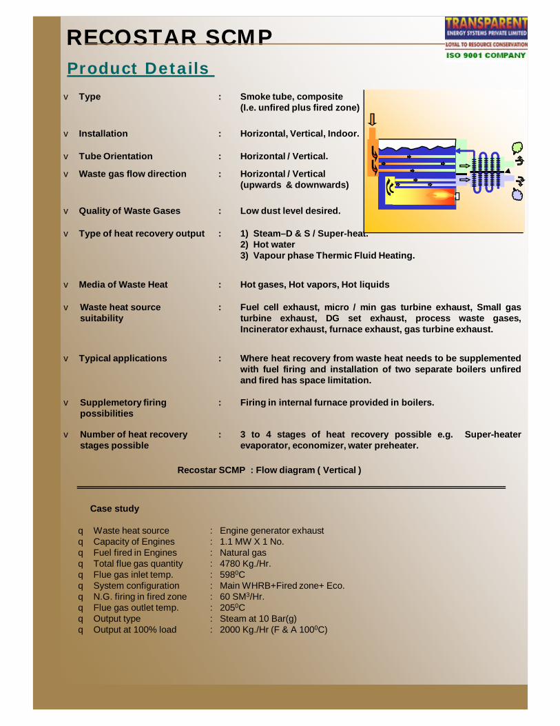
v Type : Smoke tube, composite (I.e. unfired plus fired zone)
v Installation : Horizontal, Vertical, Indoor.
v Tube Orientation : Horizontal / Vertical.
v Waste gas flow direction : Horizontal / Vertical (upwards & downwards)
v Quality of Waste Gases : Low dust level desired.
v Type of heat recovery output : 1) Steam–D & S / Super-heat.2) Hot water3) Vapour phase Thermic Fluid Heating.
v Media of Waste Heat : Hot gases, Hot vapors, Hot liquids
v Waste heat source suitability
: Fuel cell exhaust, micro / min gas turbine exhaust, Small gasturbine exhaust, DG set exhaust, process waste gases,Incinerator exhaust, furnace exhaust, gas turbine exhaust.
v Typical applications : Where heat recovery from waste heat needs to be supplementedwith fuel firing and installation of two separate boilers unfiredand fired has space limitation.
v Supplemetory firing possibilities
: Firing in internal furnace provided in boilers.
v Number of heat recovery stages possible
: 3 to 4 stages of heat recovery possible e.g. Super-heaterevaporator, economizer, water preheater.
RECOSTAR SCMP Product Details
Case study
q Waste heat source : Engine generator exhaustq Capacity of Engines : 1.1 MW X 1 No.q Fuel fired in Engines : Natural gasq Total flue gas quantity : 4780 Kg./Hr.q Flue gas inlet temp. : 5980Cq System configuration : Main WHRB+Fired zone+ Eco.q N.G. firing in fired zone : 60 SM3/Hr.q Flue gas outlet temp. : 2050Cq Output type : Steam at 10 Bar(g) q Output at 100% load : 2000 Kg./Hr (F & A 1000C)
Recostar SCMP : Flow diagram ( Vertical )
PRODUCT FEATURES
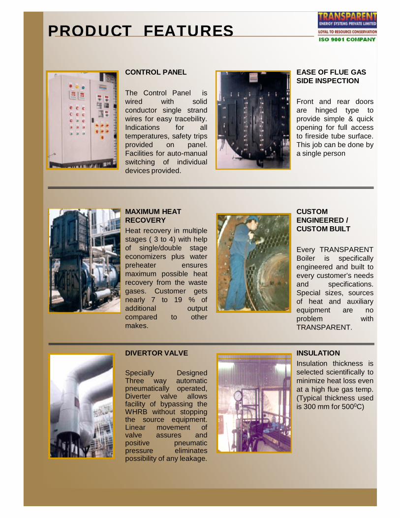
CONTROL PANEL
The Control Panel iswired with solidconductor single strandwires for easy tracebility.Indications for alltemperatures, safety tripsprovided on panel.Facilities for auto-manualswitching of individualdevices provided.
EASE OF FLUE GAS SIDE INSPECTION
Front and rear doorsare hinged type toprovide simple & quickopening for full accessto fireside tube surface.This job can be done bya single person
MAXIMUM HEAT RECOVERYHeat recovery in multiplestages ( 3 to 4) with helpof single/double stageeconomizers plus waterpreheater ensuresmaximum possible heatrecovery from the wastegases. Customer getsnearly 7 to 19 % ofadditional outputcompared to othermakes.
CUSTOM ENGINEERED / CUSTOM BUILT
Every TRANSPARENTBoiler is specificallyengineered and built toevery customer’s needsand specifications.Special sizes, sourcesof heat and auxiliaryequipment are noproblem withTRANSPARENT.
DIVERTOR VALVE
Specially DesignedThree way automaticpneumatically operated,Diverter valve allowsfacility of bypassing theWHRB without stoppingthe source equipment.Linear movement ofvalve assures andpositive pneumaticpressure eliminatespossibility of any leakage.
INSULATIONInsulation thickness isselected scientifically tominimize heat loss evenat a high flue gas temp.(Typical thickness usedis 300 mm for 5000C)

Matrix for of converting waste heat in useful form
APPLICATION SUITABILITY PRODUCT MATRIX
HOEE
LOEE
GEE
EJH
GTE
IEG
CPKG
SPF
HGP
GFG
FGFH
AC
HPC
Low Pressure Steam
Medium Pressure Steam
High Pressure Steam
Hot Thermic Fluid
Hot Water (Pressurized)
Hot Water (Non Pressurized)
Hot Air for Process (Dryer etc)
Chilled Water
Chilled Brine
Ice Making
Cold Storage
Waste Water Recycling
Power
Combustion Air Preheating
Inlet Air Cooling
Source ofWaste Heat
Useful FormOf Output
v HOEE : Heavy Oil Engine Exhaustv LOEE : Light Oil Engine Exhaustv GEE : Gas Engine Exhaustv EJH : Engine Jacket Heatv GTE : Gas Turbine Exhaustv IEG : Incinerator Exit Gasesv CPKG : Cement Plant Kiln Gasesv SPF : Steel Plant Furnacesv HGP : Hot Gases From Processv GFG : Glass Furnace Gases v FGFH : Flue Gases From Fired Heatersv AC : Air Compressorsv HPC : High Pressure Condensate
Source of Waste Heat

WHRB INSTALLATION
WHRB Installed on Natural Gas Fired Engine,
WHRB Installed on Natural Gas Fired Engine
WHRB Installed on Heavy Fuel Oil fired engine
Power Generation from waste heat in Cement Industries - Simple Rankine Cycle
Power Generation from waste heat in Cement Industries - Organic Rankine Cycle

COMPARISION
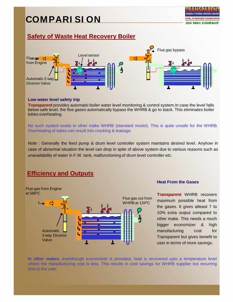
No such system exists in other make whrb (standard model). This is quite unsafe for the engine orturbine on which the WHRB is installed.Note : In case of gas fired engines or turbines, eventhough there is very little possibility of carbonaccumulation but other possibilities do exist for excessive back pressure on flue gas side. It canhappen either due to leakage of boiler tube or lube oil vapour condensation in abnormal conditions.Hence even in case of gas engines/turbines, above safety feature is of paramount importance.
Safety of Source Equipment
Back pressure control on flue gas sideTransparent provides automatic flue gas monitoring & control system. If the back pressure exceedsthe predetermined value, the Diverter Valve automatically diverts the flue gases to stack. This savesthe source (Engine or turbine) from getting subjected to excessive back pressure.
Flue gas bypass
FPS
Automatic 3 wayDivertor Valve
FPS
Flue gas from Engine
pressure sensor
Back pr. limit
Safety of Waste Heat Recovery Boiler
Flue gas bypass
SPS
Steam pr. limit
Automatic 3 wayDivertor valve
Steam pr. limit
Pressure sensorSPS
High steam pressure controlTransparent provides automatic steam pressure monitoring & control system. If the steam pressureexceeds the predetermined value, the flue gases are automatically diverted to stack. This eliminatesfrequent operation of safety relief valve.
No such system exists in other make whrb (standard model). This is quite unsafe for the WHRB. Insuch case one has to solely depend on safety valve.
Note : Frequent operation of safety valve is an undesirable situation since it is meant for ultimatesafety of boiler & supposed to operate once in a while.
COMPARISION
No such system exists in other make WHRB (standard model). This is quite unsafe for the WHRB.Overheating of tubes can result into cracking & leakage.
Note : Generally the feed pump & drum level controller system maintains desired level. Anyhow incase of abnormal situation the level can drop in spite of above system due to various reasons such asunavailability of water in F.W. tank, malfunctioning of drum level controller etc.
Safety of Waste Heat Recovery Boiler
Low water level safety tripTransparent provides automatic boiler water level monitoring & control system.In case the level falls below safe level, the flue gases automatically bypass the WHRB & go to stack. This eliminates boiler tubes overheating.
Flue gas bypass
LSL
Flue gas from Engine
Automatic 3 wayDivertor Valve
Level sensor
LSL
In other makes, eventhough economizer is provided, heat is recovered upto a temperature levelwhere the manufacturing cost is less. This results in cost savings for WHRB supplier but recurringloss to the user.
Heat From the Gases
Transparent WHRB recoversmaximum possible heat fromthe gases. It gives atleast 7 to10% extra output compared toother make. This needs a muchbigger economizer & highmanufacturing cost forTransparent but gives benefit touser in terms of more savings.
Efficiency and Outputs
Automatic3 way Divertor Valve
Flue gas from Engine at 5860C
Flue gas out from WHRB at 1340C

COMPARISIONDivertor Valve
From Engine Linearmovement
• Automatic pneumatically operated.• Linear movement of valve(poppet). No
possibility of jamming.• Positive pneumatic pressure acts as good
sealing force continuously when the valvereaches the respective positions. Thepoppet is pressed against the valve seatby pneumatic pressure eliminatingpossibility of any leakage.
• Force is applied at center of poppetensuring equal distribution throughout thesealing edges.
• Made of Stainless steel which canwork upto 8500C continuously.
• Manually operated.• Swing type movement of valve(flap).
Possibility of jamming.• No positive force is applied after the flap
reaches its respective positions.Themechanical play in the gearbox results insmall opening due to self weight of flap &flue gas back pressure. This can result inleakage in the long run.
• Force is applied at one end of flap. Thisresults in unequal force distribution.Thedistant edge gets less force.
• Made of carbon steel alloy which is notsuitable for more than 5000C.
To WHRB
Possible leakage
From Engine
Flap
Swing typemovement
Transparent Make Other Make
Transparent Group of CompaniesTransparent Group Companies, are technology leaders working in the field of Co-generationSystems( CHP), Ammonia Absorption Refrigeration Plants (AARP), Waste Heat Recovery Systems,Energy Conservation Contracts, Biomass Gasification, Water Recycling Plants. Superefficient Boilers,Energy and Water consultancy, Pollution control, Drying Plants , Noise abatement Systems etc. having Indian Patents for many of itsproducts.
Transparent Energy Systems Private LimitedOur company was incorporated on 16th April, 1986 with the name of Vapor Energy Machines Private Limited. The first commercial production was started in January, 1988. The name of the company was changed from Vapor Energy Machines Private Limited to Transparent Energy Systems Private Limited on 18th December, 1995.
1. Co-generation Systems - www.tesplcogen.comCogeneration Systems involving combined generation of- Power - Heat - Refrigeration / Chilling - Water Recycling / Desalination by multistage evaporation.Fuels and energy sources for Cogeneration.- Natural Gas - Heavy Fuel Oil (HFO) - Coal - Process Waste Heat - Biogas - HSD / Kerosene / LDO - BiomassTypes of Cogeneration Systems- Steam Engine / Turbine Based Co-generation - Reciprocating Engine Generator Based Co-generation - Gas Turbine Based Co-generation
2. Ammonia Absorption Refrigeration Plants- www.tesplaarp.com (Technology collaboration with Mattes Engineering GmbH, Germany)- Refrigerant Evaporators - Refrigerant Circulation Systems - Air Handling Units - Accessories - Flash Vessels - Ammonia Vaporizers - Turnkey Refrigeration Contracts.
3. Heat Recovery Systems – www.heatrecovery-system.comWaste Heat Recovery Boilers - Finned Tube - Water Tube - Smoke Tube Waste Heat Recovery Thermic Fluid Heaters Heat Recovery & Efficiency improvement Retrofits- Combustion Air Preheater - Economisers ( Smoke tube / water tube / finned tube type) - Condensate Recovery Systems- Blow Down Heat Recovery Systems - Flash Steam Recovery Systems
4. Boilers & Heaters – www.tespl.com (Technology Collaboration with Lamont Kessel GmbH, Germany)- 96% Superefficient Oil / Gas Fuelled Boilers - 93% Superefficient Thermic Fluid Heaters / Hot Air Generators - 89% Superefficient Agrofuelled / Coal Fired Boilers. - Superefficient High Pressure steam Boilers, (Oil / Gas / Coal / Biomass Fired)
for Cogeneration application 5. Energy Conservation Projects – www.tespl.com
Conservation of Electrical heating to Steam / Thermic Fluid / Hot Water Heating
6. Water Treatment Plants & Other Accessories – www.tespl.com
7. Bio mass Gasification - www.tespl.com(Technology collaboration with Bioenergie Beratung Bornim GmbH, Germany)
- Wet and Dry Fermentation of solid, semi solid and liquid biomass, Bio Diesel and Ethanol production
Transparent Technologies Private Limited - www.ttplpune.com
1. Dryers- spray Flash/Fluid Bed/ Flash 2. Coolers - Spray Coolers (Closed / Open Circuit) / Fluidized Bed Coolers / Bulk Flow Coolers
3. Granulators -Spray Granulators / Fluidized Bed Granulators / Rotary Granulators 4. Waste to Energy Incinerators
5. Evaporators and ConcentratorsEcokleen Pollution Control Pvt. Ltd. - www.ecokleen.com
1.Pollution Control- Scribbers/ Bag Filters / Cyclones / Multicyclones 2. Flue Gas Desulpharisation – Wet- Wet/Dry Wet/ Dry Dry Systems3. Fume and Dust Extraction Plants 4. Air stripping plants & Airborn Solvent Vapor Recovery Plants 5. Thermal Oxidation System of Airborne Solvent Vapors 6. Bulk Material Handling
Decimin Control Systems Pvt. Ltd. - www.decimin.com
Noise abatement products and systems ( in collaboration with IAC BOET STOPSON, France)- Acoustic Canopies for D G sets, Machineries- Noise silencers for engines, blowers, compressors, valve exhaust, acoustic louvers and baffles.- Gas turbine inlet / outlet systems.- ISO containerized DD sets / compressors engine house acoustic.
Ecosustain Energy Systems Pvt. Ltd. - www.ecosustainenergy.com (Co Operation Agreement with ShandongQingeng Thermal Power Equipment Co. Ltd.)
1. Steam Turbine Generators - Stage Extraction / Condensing / Back Pressure Multi-Stage / Single – Stage Superheated / Saturated Steam inlet.2. Steam Turbine Drives for Pumps / Blowers / Compressors. 3. Steam Condensers - Water cooled shell and tube, Air cooled finned tube
Ecosustain Technologies Pvt. Ltd. . - www.ecosustain.co.inWater Recovery and reuse from effluents - Turnkey solutions through CECIC - Conceptualization, Engineering, Coordination, Inspection, Commissioning
Vital Technologies used - Ultra filtration, Reverse osmosis (RO) . - Super efficient multistage evaporators and crystalisers- Ultra-violet based wet oxidation systems - High pressure thermal wet air oxidation systems- Absorption and ion exchange - Drying and incineration - Waste heat utilization