WASTE HEAT RECOVERY BOILERS - Johnston Boiler
8
Johnston Boiler Company 300 Pine Street, P.O. Box 300 Ferrysburg, MI 49409‐0300 P. 616‐842‐5050 F. 616‐842‐1854 www.johnstonboiler.com WASTE HEAT RECOVERY BOILERS
Transcript of WASTE HEAT RECOVERY BOILERS - Johnston Boiler

Johnston Boiler Company 300 Pine Street, P.O. Box 300 Ferrysburg, MI 49409‐0300 P. 616‐842‐5050 F. 616‐842‐1854 www.johnstonboiler.com
WASTE HEAT RECOVERY BOILERS

2
MAKE EVERY BTU COUNT
Waste heat is a valuable resource. Johnston Boiler Company’s line of single and triple pass Waste Heat Recovery (WHR) boilers offer your company a way to save valuable energy, energy typically lost in waste heat. The WHR se-ries are used in petrochemical plants, refineries, steel mills, ore converters, brick or cement plants, glass works, and food processing plants. The WHR boiler extracts the BTU from these exhaust gasses, putting them to use generating plant steam or hot water.
Example: A combination waste heat recovery unit (See FIG. 1) with an auxiliary gas/oil burner returned its capital in-vestment 18 months after installation in an east coast chemical plant. Estimates indicate that #2 fuel oil us-age dropped from 45 gallons per hour to approximately 7 gallons per hour. As an added benefit, the lower fuel consumption made it possible for management to add to its built-in fuel reserve for periods when fuel supplies are in short supply. This “Hybrid” WHR boiler with supplemental fuel burners generates heat continuously to meet plant steam or hot water requirements. During periods when the heat content of waste exhaust gas is insufficient, the sup-port burner will fire to provide steam within the desired range of operation.
Find out how you can get the most out of every BTU. Call Johnston Boiler Company and our design team will use our resources to help you save your resources.
WHR Boilers allow for: High efficiency heat transfer Minimum gas side pressure drop Reduced installation time and cost Use of a wide range of gas types, gas weights and gas temperatures
Design and Operating Range
Note: Design and operating conditions listed and nominal. Increased capac-ities and higher design pressures may be available for some applications.
Saturated Steam Lbs/hr 2,000—165,000
Steam Design Pressure PSIG 15—300
Hot Water MBH 2,000—165,000
Hot Water Design Pressure PSIG 30—160
Waste Heat Inlet Gas Temperature °F 600—2,500
Waste Heat Mass Gas Flow Lbs/hr 1,000—400,000
FIG. 1
Since 1864 Johnston Boiler Company has built a reputation on innovative designs and rigid adherence to quality. We believe that boilers must be dependable. Today, as in 1864, Johnston’s employees take personal pride in the quality and craftsmanship of each boiler produced.

As natural gas and oil prices continue to rise it is increasingly important to find ways to conserve fuel costs. Johnston Boiler Company’s line of WHR boilers are designed to recover heat from a variety of sources. Reducing fuel con-sumption is the key behind the Johnston Boiler Company WHR system. The WHR will save you money, money which can be reinvested into more profitable revenue streams.
Think of the WHR as a Green Money Saving Machine
Reducing Fuel Costs By Conserving EnergyReducing Fuel Costs By Conserving EnergyReducing Fuel Costs By Conserving Energy
3

We can calculate the energy conservation and applicable fuel cost reduction for this application and compare the zero fuel cost of Johnston Boiler Company’s WHR boiler with the fuel cost of a traditional gas or oil fired boiler, using the following equation.
BTU/Lb.
Steam X
Lb./Hr.
Steam Capacity
% Efficiency of
Fuel Fired Boiler X
BTU/Gal. or Cu. Ft.
of Fuel Fired
X $/Gal. or Cu/Ft.
Fuel Fired =
Fuel Cost
Per Hour
Example: Using the example from the table above with the following assumed operating conditions: Steam Operating Pressure = 100 PSIG Feedwater Temperature = 212°F Fuel Fired = #2 Oil having a HHV of 140,000 BTU/Gal. Fuel Cost = 3.58/Gal. Boiler Efficiency = 81.5% Steam Capacity = 21,165 Lb/Hr. [21,369 MBH ÷ (1,189.7 BTU/Lb. Steam @ 100 PSIG - 180.07 BTU/Lb. of
Feedwater @212°F.)]
Gas Flow Lb/Hr
Inlet Gas Temperature °F
Boiler Model Number
Gas Side Pressure Drop “
WC
Outlet Gas Temperature °F
Heat Recovered MBH
100,000 1,200 WHR-132-16 4.5 435 21,369
Following is a typical waste heat recovery application involving operating conditions relating to a Johnston Boiler Company WHR boiler installation.
X $3.58/Gal X 5,256 = $3,523,950.00/Year 187.28 =
In this example the Johnston Boiler Company waste heat recovery boiler is capable of reducing fuel costs by as much as: $402.00/Hr $9,655.00/Day $67,768.00/Week $293,662.00/Month
Estimated fuel savings are based on a conservative duty cycle of 60%
Factor this savings out for one year and the numbers become staggering
1009.63 X 21,165
81.5% X 140,000
4
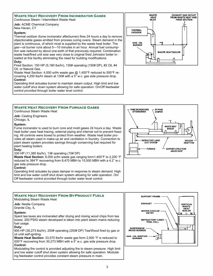
Waste Heat Recovery From Incinerator Gases Continuous Steam / Intermittent Waste Heat
Job: ACME Chemical Company New Haven, CT
System: Thermal oxidizer (fume incinerator afterburner) fires 24 hours a day to remove objectionable gases emitted from process curing ovens. Steam demand in the plant is continuous, of which most is supplied by the waste heat boiler. The gas—oil burner runs about 5—10 minutes in an hour. Annual fuel consump-tion was reduced by about one-sixth of that previously required. Combination waste heat/fired unit size was very close to original fired Johnston boiler in-stalled at this facility eliminating the need for building modifications. Duty: Fired Section: 150 HP (5,180 lbs/hr), 130# operating (150# DP), #2 Oil, #4 Oil, or Natural Gas. Waste Heat Section: 4,000 scfm waste gas @ 1,400°F reduced to 500°F re-covering 4,250 lbs/hr steam at 130# with a 5” w.c. gas side pressure drop. Control: Operating limit actuates burner to maintain steam output. High limit and low water cutoff shut down system allowing for safe operation. On/Off feedwater control provided through boiler water level control.
Waste Heat Recovery From Furnace Gases Continuous Steam Waste Heat
Job: Casting Engineers Chicago, IL
System: Fume incinerator is used to burn core and mold gases 24 hours a day. Waste heat boiler uses heat tracing, external piping and internal coil to prevent freez-ing. All controls were boxed to protect from weather. Waste heat boiler pro-vides all steam used in make-up air and ventilation in foundry. Connection to plant steam system provides savings through conserving fuel required for plant heating boilers. Duty: 330 HP (11,385 lbs/hr), 13# operating (15# DP) Waste Heat Section: 6,000 scfm waste gas ranging form1,400°F to 2,200 °F reduced to 384°F recovering from 8,470 MBH to 15,500 MBH with a 4.2” w.c. gas side pressure drop. Control: Operating limit actuates by-pass damper in response to steam demand. High limit and low water cutoff shut down system allowing for safe operation. On/Off feedwater control provided through boiler water level control.
Waste Heat Recovery From By-Product Fuels Modulating Steam Waste Heat
Job: Nestle Company Granite City, IL
System: Spent tea laves are incinerated after drying and mixing wood chips from tea boxes. 200 PSIG steam developed is taken into plant steam mains reducing fuel usage. Duty: 905 HP (30,273 lbs/hr), 200# operating (250# DP) Tea/Wood fired by gas or oil until self-igniting. Waste Heat Section: 33,570 lbs/hr waste gas form 2,000 °F is reduced to 500°F recovering from 30,273 MBH with a 5” w.c. gas side pressure drop. Control: Modulating fire control is provided adjusting fire to steam pressure. High limit and low water cutoff shut down system allowing for safe operation. Modulat-ing feedwater control provides constant steam pressure in main.
5

WHR‐1 Single Pass Waste Heat Recovery Boiler
Standard Trim/Equipment: Insula on with sheet metal jacket Flanged exhaust gas inlet/outlet Hinged front and rear tube access doors Structural steel base Manholes and handholes for inspec on and cleaning Steam trim and water column including related piping
Gauge glass with valves, try cocks, and chain operator Safety relief valves Steam pressure gauge Blowdown valves Main Blow‐off valves Primary low water cutoff with pump control
Notes: 1. Models listed are representa ve tabula ons only. Consult factory for specific applica ons 2. Consult factory for specific dimensions, weights, and capaci es
6
Dimension WHR1
54X114
WHR1
58X115
WHR1
64X115
WHR1
64X131
WHR1
72X131
WHR1
80X131
WHR1
80X179
WHR1
85X179
WHR1
91X216
WHR1
99X216
WHR1
108X216
WHR1
112X244
WHR1
112X268
WHR1
123X268
A 54 58 64 64 72 80 80 85 91 99 108 112 112 123
B 114 114 114 130 130 130 178 178 215 215 215 243 267 267
C 129 130 130 148 149 150 200 201 239 241 242 271 295 296
D 81 85 91 93 101 109 111 116 122 130 140 144 144 155
E 60 66 70 72 77 84 86 91 97 102 108 112 112 121
F 18 18 18 20 20 20 22 22 22 22 22 22 22 22
G 67 71 77 77 85 93 93 98 104 112 121 125 125 136
H 12 14 15 16 18 21 21 23 25 28 31 32 32 35
I 1.50 1.50 2 2 2 2 2 2 2 2 2 2 2 2
K 51 54 60 60 66 72 75 80 84 90 100 102 102 112
L 81 81 81 102 102 102 132 132 168 168 168 180 204 204
M 107 107 107 123 123 123 169 169 206 206 206 234 258 258
N 75 79 86 89 95 103 105 110 116 124 134 138 138 149
O 36 36 36 36 36 36 36 36 36 36 36 36 36 36
MODEL NUMBER

7
WHR‐3 Three Pass Waste Heat Recovery Boiler
Notes: 1. Models listed are representa ve tabula ons only. Consult factory for specific applica ons. 2. Consult factory for specific dimensions, weights, and capaci es
Standard Trim/Equipment: Insula on with sheet metal jacket Flanged exhaust gas inlet/outlet Hinged front and rear tube access doors Structural steel base Manholes and handholes for inspec on and cleaning Steam trim and water column including related piping
Gauge glass with valves, try cocks, and chain operator Safety relief valves Steam pressure gauge Blowdown valves Main Blow‐off valves Primary low water cutoff with pump control
Dimension WHR3
54X114
WHR3
58X115
WHR3
64X115
WHR3
64X131
WHR3
72X131
WHR3
80X131
WHR3
80X179
WHR3
85X179
WHR3
91X216
WHR3
99X216
WHR3
108X216
WHR3
112X244
WHR3
112X268
WHR3
123X268
A
B
C
D
E
F
G
H
I
K
L
M
N
O
P
MODEL NUMBER
Distributed By: Johnston Boiler Company 300 Pine Street, P.O. Box 300 Ferrysburg, MI 49409‐0300 P. 616‐842‐5050 F. 616‐842‐1854 www.johnstonboiler.com
Project Notes:
Sketch:
November 2011 Bulle n: WHR
8