Wasserzuführgerät Water Supply Unit Cuve d’ Alimentation d ... · proper repair or if...
16
Betriebsanleitung. . . . . . . . . . . . . . . . . . . . . . . . . . . . . . . . . 3 - 6 Instructions for use . . . . . . . . . . . . . . . . . . . . . . . . . . . . . . 7 - 10 Mode d’emploi . . . . . . . . . . . . . . . . . . . . . . . . . . . . . . . . 11 - 14 DE GB FR Wasserzuführgerät Water Supply Unit Cuve d’ Alimentation d’ Eau 0045 Geräte für Industrie und Handwerk
Transcript of Wasserzuführgerät Water Supply Unit Cuve d’ Alimentation d ... · proper repair or if...

Betriebsanleitung. . . . . . . . . . . . . . . . . . . . . . . . . . . . . . . . . 3 - 6
Instructions for use . . . . . . . . . . . . . . . . . . . . . . . . . . . . . . 7 - 10
Mode d’emploi . . . . . . . . . . . . . . . . . . . . . . . . . . . . . . . . 11 - 14
DE
GB
FR
WasserzuführgerätWater Supply UnitCuve d’ Alimentation d’ Eau
0045
Geräte für Industrie und Handwerk
RZ_976213.qxd 12.03.2007 13:31 Uhr Seite 1

2
RZ_976213.qxd 12.03.2007 15:34 Uhr Seite 2

3
InhaltsverzeichnisWichtige Sicherheitshinweise . . . . .3Technische Daten . . . . . . . . . . . . .4Inbetriebnahme . . . . . . . . . . . . . . .4Entleerung und Wartung . . . . . . . . .5Konformitätserklärung . . . . . . . . . .6
Wichtige SicherheitshinweiseReparaturen an diesem Gerät sind nurdurch die Servicestellen durchzufüh-ren. Ersatzteile sollten Sie bei IhremFachhändler bestellen. Soweit nichtvorrätig, besorgt er diese schnellstens.
● Dieses Gerät ist ausschließlich fürdie Wasserversorgung von Diamant-bohrgeräten zu verwenden.
● Vor jeder Inbetriebnahme des Gerä-tes die Funktion überprüfen, be-sonders auf Dichtheit von Schlauch-anschluss und Schraubverbindungenachten. Material auf Rissbildung,Sprödheit und Korrosion prüfen.
● Vor jeder Inbetriebnahme ist das Si-cherheitsventil zu überprüfen! Hierzudie Pumpe einsetzen und verschrau-ben. Pumpe solange betätigen, bisam Manometer kein Druckanstiegmehr sichtbar ist (Sicherheitsventilbläst Druck ab). Hierbei darf dermaximal angezeigte Manometer-druck 6,6 bar nicht übersteigen.
● Ein befülltes Gerät nicht längere Zeitstarker Sonneneinstrahlung ausset-zen. Betriebstemperaturen dürfen50°C nicht überschreiten.
● Gerät so aufbewahren, dass es nichtvon Kindern benutzt werden kann.
● Ein befülltes Gerät nicht unbeauf-sichtigt am Einsatzort stehen lassen.
● Gerät nicht unnötig lange Zeit unterDruck stehen lassen.
● Nach Gebrauch Behälter sofort entlee-ren und anschließend gut austrocknen(siehe Entleerung und Wartung).
● Wir empfehlen nach 5 jähriger Be-nutzung das Wasserzuführungsgerätsicherheitshalber einer besonderseingehenden Prüfung - am bestendurch den Hersteller - zu unterzie-hen. Es ist verboten, am BehälterAusbesserungen vorzunehmen.
● Achtung!Wir weisen ausdrücklich darauf hin,dass wir nach dem Produkthaftungs-gesetz nicht für durch unser Geräthervorgerufene Schäden einzustehenhaben, sofern diese durch unsachge-mäße Reparatur verursacht oder beieinem Teileaustausch nicht GLORIA-Original-Teile verwendet werden unddie Reparatur nicht vom Kunden-service oder dem autorisierten Fach-mann durchgeführt worden sind. Dieses gilt auch für Zubehörteile.
DE
RZ_976213.qxd 12.03.2007 15:34 Uhr Seite 3

4
● Die Lebensdauer des Gerätes mussdurch den Betreiber aufgrund einerGefährdungsbeurteilung unter Be-rücksichtigung der Betriebsbedin-gungen festgelegt werden. Aufgrundeiner möglichen Materialermüdungempfehlen wir dringend eine Le-bensdauer von 10 Jahren nicht zuüberschreiten.
Technische DatenTyp: 415Artikel-Nr.: 415....max. Einfüllmenge: 10 LGesamt-Behälterinhalt: 13,7 Lzul. Betriebsüberdruck : 6 barzul. Betriebstemperatur: 0°C bis
+50°CVoller Druckwechsel 0 bar bis 6 bar: max. 5000
LastwechselBehältermaterial: Stahl mit
Innenbe-schichtung
Sicherheitsventil
siehe Abb.
Zubehör Mitgelieferter Anschluss-Schlauch
InbetriebnahmeAbb.
● Vor der ersten Inbetriebnahme diemitgelieferte Schlauchleitung mon-tieren und fest verschrauben.
● Vor jeder Inbetriebnahme ist das Si-cherheitsventil Abb. (unterhalbdes Einfülltrichters) zu überprüfen.
● Hierzu die Pumpe einsetzen und ver-schrauben.
2
1
2
1
2
RZ_976213.qxd 12.03.2007 15:34 Uhr Seite 4

5
● Pumpe solange betätigen, bis amManometer kein Druckanstieg mehrsichtbar ist (Sicherheitsventil blästDruck ab). Hierbei darf der maximalangezeigte Manometerdruck 6,6 barnicht übersteigen.
● Prüfen, ob das Gerät drucklos ist,gegebenenfalls roten Druckknopfbetätigen.
● Pumpe durch Linksdrehung heraus-schrauben - hierzu vorab Pumpenge-stänge entriegeln, um 180° drehenund über den Rücken der Verriege-lungszapfen am Pumpengehäuse dieSchraubkraft übertragen.
● Behälter mit Wasser füllen. Achtung!Maximale Füllmenge beachten.
● Pumpe einsetzen und verschrauben.● Wasserzuführgerät und Bohrgerät
durch mitgelieferten Schlauch ver-binden.
● Pumpe betätigen, bis ein Betriebs-überdruck von 6 bar (roter Markie-rungsstrich am Manometer) im Be-hälter erreicht ist.
Überprüfung des Wasserstandes
Abb.
● Bei drucklosem Gerät (roten Knopfdrücken) durch Hochhalten destransparenten Schlauches am Gerät,entspricht der Wasserstand imSchlauch dem Wasserstand im Be-
hälter und kann an der Füllskala desBehälters abgelesen werden(Schlauchwaagenprinzip).
Entleerung und Wartung● Druckentlastungsventil - roter Druck-
knopf - betätigen, bis das Gerätdruckfrei ist.
● Die Pumpe wird vorsichtig, zunächstnur einige Gewindegänge durchLinksdrehung gelöst, damit evtl. imBehälter verbliebene Druckluft ent-weichen kann. Erst dann die Pumpeganz herausschrauben und aus demBehälter nehmen.
● Restwasser ausleeren.● Nach dem Entleeren das Gerät hän-
gend, Öffnung nach unten, trocknenlassen.
● Gerät drucklos lagern.
3
10
9
8
7
6
5
3
RZ_976213.qxd 12.03.2007 15:34 Uhr Seite 5
6
● Die Lebensdauer wird erheblich ver-längert wenn ab und zu der Dich-tungsring zwischen Pumpe und Be-hälter sowie innerer O-Ring mit harz-und säurefreiem Fett geschmiertwerden.
● Gerät vor Frost schützen.● Es ist verboten, am Behälter Ausbes-
serungsarbeiten (schweißen, löten)vorzunehmen.
● Bei Reparaturen nur Original GLO-RIA-Ersatzteile verwenden.
● Wichtiger Hinweis! Überdurch-schnittlich starke Beanspruchung auf-grund der Betriebsweise (einschl. desTransports zum Einsatzort und der Auf-bewahrung bei Nichtbenutzung), Um-gebungseinflüsse (des Einsatzortesund des Aufbewahrungsortes beiNichtbenutzung ), mangelhafte War-tung und Pflege können zu vorzeitigemVerschleiß des Gerätes führen. Essollte daher vor jeder Benutzung auf si-cheren und betriebsfähigen Zustand,zumindest jedoch auf äußerlich er-kennbare Schäden, geprüft werden.Insbesondere bei Auftreten sicherheits-bedenklicher Mängel, jedoch mindes-tens alle 12 Monate haben Sachkun-dige, am besten der Wartungsdienstdes Herstellers, zu prüfen, ob ein ge-fahrloser Betrieb weiterhin möglich ist.
Die am Betriebsort geltenden natio-nalen Vorschriften hinsichtlich desArbeitsschutzes sowie die geltendennationalen Vorschriften über den Be-trieb sind zu befolgen.
Technische Änderungen vorbehalten!
CE-Konformitätserklärung für eineBaugruppe im Sinne von Artikel 3,Absatz 2 der Richtlinie über Druck-geräte 97/23/EG
BRILL GLORIA Haus- und Gartengeräte GmbHDärmannsbusch 7D-58456 Witten
bestätigt, dass das Wasserzuführgerät
Art.-Nr. 415....Zertifikats – Nr. (Modul A1):07202 1403 Z 0003 / 7 / D001
mit der Richtlinie über Druckgeräte97/23/EG und anerkannten Regeln der Technik übereinstimmen.
Das Konformitätsbewertungsverfahrenfür die Baugruppe und für den Behälter basiert auf dem Modul A1 (Anhang III)der Richtlinie 97/23/EG.Benannte Stelle: TÜV NORD SystemsGmbH & Co.KG.
Witten, 08.03.07
Hans-Georg Wellerdiek(Konstruktionsleiter)
RZ_976213.qxd 12.03.2007 15:34 Uhr Seite 6

7
Table of ContentsImportant Safety Precautions . . . . . .7Technical data . . . . . . . . . . . . . . . .8Getting Started . . . . . . . . . . . . . . .8Emptying and Servicing . . . . . . . . . .9Declaration of conformity . . . . . . . .10
Important Safety PrecautionsRepairs to the equipment shouldonly be carried out by Service Sta-tions. Order spare parts from yourauthorised dealer. If the requiredparts are not in stock, he will pro-cure them for you as quickly aspossible.● This unit must be used solely for
supplying water to diamond drillingrigs.
● Check the functioning of the unit eachtime before startup, and make a spe-cial check of the hose connection andthe screw connectors. Check the ma-terial for tears, brittleness and corro-sion.
● The safety valve must be checkedeach time before startup! Insert thepump and screw it up tight. Operatethe pump until the pressure gaugeshows no further increase (the safetyvalve blows off the excess pressure).
The maximum pressure shown onthe pressure gauge must never ex-ceed 6.6 bar.
● Do not leave the filled tank in strongsunshine. Do not exceed operatingtemperatures of 50°C.
● Store the unit in a place out of thereach of children.
● Do not leave a ready-filled unit unat-tended at the place where it is beingused.
● Do not leave the unit under pressureunnecessarily for longer periods oftime.
● Thoroughly clean out the tank imme-diately after use and then dry it well(see Emptying and Servicing).
● As a precautionary measure, we re-commend that the water supply unitbe subjected to a particularly thoroughinspection every five years, preferablyby the manufacturer. Repairs to the tank are not permitted.
● Caution!Please note that under product liabil-ity law we are not liable for damageresulting from the use of our productif such damage was caused by im-proper repair or if GLORIA-originalreplacement parts were not used toreplace defective or worn-out partsand the repair was not carried out by our Customer Service or by an
GB
RZ_976213.qxd 12.03.2007 15:34 Uhr Seite 7
8
authorized service technician. This also applies to accessories.
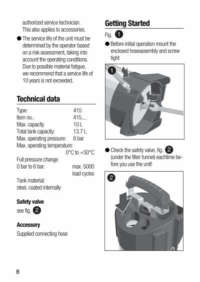
● The service life of the unit must bedetermined by the operator basedon a risk assessment, taking into account the operating conditions.Due to possible material fatigue, we recommend that a service life of10 years is not exceeded.
Technical dataType: 415 Item no.: 415....Max. capacity 10 LTotal tank capacity: 13.7 LMax. operating pressure: 6 barMax. operating temperature:
0°C to +50°CFull pressure change 0 bar to 6 bar: max. 5000
load cyclesTank material:steel, coated internally
Safety valve
see fig.
Accessory
Supplied connecting hose
Getting StartedFig.
● Before initial operation mount theenclosed hoseassembly and screwtight
● Check the safety valve, fig. (under the filter funnel) eachtime be-fore you use the unit!
2
1
2
1
2
RZ_976213.qxd 12.03.2007 15:34 Uhr Seite 8

9
● Insert the pump andsrew it in.● Operate the pump until the pressure
gauge shows notfurther increase inpressure (the safety valve blowsoffthe excess pressure). The maximumpressure shown on thepressuregauge must never exceed 6,6 bar.
● Make sure the unit is not pressur-ized. If necessary, press red push-button.
● Remove the pump by turning it to theleft. To do this, first release the pistonrod, turn it 180° and transfer the-screw force via the back of the lock-ing pins on the pumphousing.
● Fill tank. Caution!Observe the maximum filling level
● Insert pump again and screw tightby turning in a clockwisedirection.
● Connect unit and rig with suppliedhose.
● Operate pump until a max. gaugepressure of 6 bar is rea-ched (redmark on gauge).
Check of water levelFig.● When the unit is not under pressure
(press red button), hold upthe trans-parent hose. The water level in thehose is the same as that in the con-tainer and it can be read off the fill-ing level scale on the container(water balance principle).
Emptying and Servicing● Operate the pressure relief valve
(red button) until the unit is no longerunder pressure.
● Open the pump carefully, at first onlya few turns to the left, to allow anycompressed air still in the tank toescape. Only then should the pumpbe unscrewed completely and re-moved from the tank.
● Empty any remaining water.
● After emptying, hang up the openunit to dry.
● Store the unit in a depressurisedcondition.
● The service life of the unit will begreatly extended by occasionally ap-plying resin and acid-free grease tothe sealing ring between the pumpand the tank and to the inner O ring.
3
10
9
8
7
6
5
3
RZ_976213.qxd 12.03.2007 15:34 Uhr Seite 9

10
● Protect the unit against frost.
● It is forbidden to make changes tothe tank (welding, brazing, etc.).
● Only use original GLORIA spare partsfor repairs.
● Important note! Undue straincaused by the mode of operation (in-cluding transport to site where usedand storage when not in use), envi-ronmental influences (at the site where used and where stored when not in use), insufficient maintenance and care may lead to prematurewear and tear of the unit. For thisreason, always check the unit beforeuse to make sure that it is in a safeand operable condition, at least,however, for outwardly recognisablesigns of damage. To ensure contin-ued safe operation of the unit, atechnician, preferably from the man-ufacturer’s service department,should inspect the unit in the eventof defects affecting safe operation, inparticular, but at a minimum every12 months.
The national regulations applicable at the place of use regarding safetyat work and the national regulations applicable to the company must becomplied with.
We reserve the right to make technical changes!
CE-statement of conformity for amodule within the meaning of Art. 3, section 2 of the directive onpressurized equipment 97/23/EG
BRILL GLORIA Haus- und Gartengeräte GmbHDärmannsbusch 7D-58456 Witten
confirms that the water supply unit
Item no. 415....certificate - no. (Module A1):07202 1403 Z 0003 / 7 / D001
comply with the directive on pressurizedequipment 97/23/EG and the recognized rules of technology .
The procedure for the statement of con-formity for the module and for the tankis based on module A1 (Appendix III) ofdirective 97/23/EC.
Notified body, TÜV NORD SystemsGmbH & Co. KG.
Witten, 08.03.07
Hans-Georg Wellerdiek (Design Manager)
RZ_976213.qxd 12.03.2007 15:34 Uhr Seite 10

11
Table des matièresImportantes consignes de sécurité .11Caractéristiques techniques . . . . . .12Mise en service . . . . . . . . . . . . . .12Vidage et entretien . . . . . . . . . . .13Déclaration de conformité . . . . . . .14
Importantes consignes desécuritéLes réparations des appareils nedoivent être effectuées que par lesservices. Commander les piècesde rechange chez le revendeur. Sices pièces ne sont pas en réserve,il se les procurera rapidement.● Cette cuve doit être utilisée unique-
ment pour l’alimenta-tion d’ eau desappareils de forage au diamant.
● Avant chaque mise en service du va-porisateur, en vérifier le fonctionne-ment et veiller en particulier à l'étan-chéité du raccord de flexible et desraccords vissés. Contrôler le maté-riau pour s'assurer qu'il ne comporteni fissures, ni porosité, ni corrosion.
● Avant chaque mise en service, con-trôler la vanne de sécurité! Pour cefaire, installer la pompe et la visser.Actionner la pompe jusqu'à ce qu'iln'y ait plus de montée en pressionnotable sur le manomètre (la vannede sécurité dépressurise). La pres-
sion maximale indiquée sur lemanomètre ne doit pas dépasser6,6 bars.
● Ne pas exposer trop longtemps leréservoir de produit de vaporisationen plein soleil. Ne pas dépasser destempérature de service de 50°C.
● Ranger l'appareil de façon à ce qu'ilne soit pas accessible aux enfants.
● Ne pas laisser un appareil remplisans surveillance sur le lieu d'utilisa-tion.
● Ne pas laisser inutilement l’appareilsous pression pendant une périodeprolongée.
● Après utilisation, nettoyer immédia-tement et méticuleusement l'appa-reil; bien le faire sécher ensuite (voirVidage et entretien).
● Par précaution, nous conseillons defaire contrôler de façon approfondieles pulvérisateurs sous pression depréférence par le constructeur aubout de 5 années d’utilisation. Il estinterdit de procéder à des transfor-mations du réservoir.
● Attention ! Nous attirons expressément l'attentionsur le fait que nous ne pouvons pasêtre tenus responsables pour les dom-mages dus à nos appareils, conformé-ment à la loi sur la responsabilité desappareils, quand ceux-ci ont été répa-rés de façon non conforme, quand lespièces de rechange utilisées ne sont
FR
RZ_976213.qxd 12.03.2007 15:34 Uhr Seite 11

12
pas des pièces de rechange d'origineet quand la réparation n'a pas été ef-fectuée par le service après-vente ou lespécialiste autorisé. Ceci s'appliqueégalement aux accessoires.
● L’exploitant doit fixer la durée de vie del’appareil sur base d’une appréciationdu danger, en tenant compte desconditions de service. En raison d’uneéventuelle fatigue du matériau, nousrecommandons vivement de ne pasdépasser une durée de vie de 10 ans.
Caractéristiques techniquesType: 415Référence: 415....Quantité de remplissage max.: 10 LContenu global du réservoir: 13,7 LSurpression de service autorisée: 6 barsTempérature de service autorisée: 0°C à +50°CChangement de pression de 0 bar à 6 bar: maxi. 5000
alternances d'effortMatériau du réservoir:acier, intérieur recouvert
Soupape de sécurité:
voir fig.
Accessoire: flexible de raccordement livré avec leréservoir
Mise en serviceFig.
● Avant la première mise en servicemonter le flexibleet visser soigneuse-ment.
● Avant chaque mise en service, con-trôler la vanne de sécurité fig. (audessous de la trémie de remplis-sage)!
● Pour ce faire, installer la pompe et lavisser.
2
1
2
1
2
RZ_976213.qxd 12.03.2007 15:34 Uhr Seite 12

13
● Actionner la pompe jusqu’à ce qu’iln’y ait plus d’ une augmentation depression sur le manomètre (la vannede sécurité dépressurise). La pres-sion maximale indiquée sur le mano-mètre ne doit pas dépasser 6,6 bars.
● Vérifier que le réservoir n’est passous pression; le cas éché-ant, ap-puyer sur le bouton-poussoir rouge.
● Dévisser la pompe en la tournantvers la gauche - pour cefaire déver-rouiller d’abord la tringlerie depompe, la tourner à180° et transfé-rer la force de vissage par le dos dutourillonde verrouillage sur le carterde pompe.
● Remplir l'appareil. Attention !Observer la quantité de remplissagemax. (10 litres)
● Remettre et revisser la pompe entournant dans le sens desaiguillesd’une montre.
● Relier la cuve sous pression à l’ap-pareil de forage au diamant aumoyen du flexible livré avec.
● Actionner la pompe jusqu’à obtenirune surpression maximale de 6 bars(repère rouge sur le manomètre).
Contrôle du niveau d’eau
Fig.
● Lorsque la cuve n’est pas sous pres-sion (appuyer sur le bouton rouge),tenir en l’air le flexible transparent de
la cuve. Le niveau dans le flexiblecorrespond au niveau d’eau dans lacuve et peut être lue directement surl’échelle de remplissage de la cuve(principe des vases communicants!).
Vidage et entretien● Actionner le détendeur - bouton-
poussoir rouge - jusqu’à dépressuri-sation de l’appareil.
● La pompe est desserrée avec pré-cautions, d’abord de quelques toursvers la gauche, pour que l’air souspression restant encore dans le ré-servoir puisse s’échapper. Ce n’est qu’ensuite que la pompepeut être entièrement dévissée et re-tirée du réservoir.
● Vider l’eau qui reste.● Après avoir vidé l’eau, laisser sécher
la cuve oúverte et l’ac-crocher.
3
10
9
8
7
6
5
3
RZ_976213.qxd 12.03.2007 15:34 Uhr Seite 13

● Stocker l'appareil décompressé.● La durée de vie est nettement prolon-
gée quand on graisse de temps àautre le joint entre la pompe et le ré-servoir, ainsi que le joint torique inté-rieur, avec une graisse résine et sansacides.
● Protéger l'appareil contre le gel.● Il est interdit de procéder à des tra-
vaux de retouchage sur l'appareil(soudage, brasage).
● Pour les réparations, n’utiliser quedes pièces de rechange d’origineGLORIA.
● Remarque importante ! Les sollici-tations extrêmes en raison du moded’utilisation (y compris le transportjusqu’au lieu d’application et le stoc-kage en cas de non utilisation), les in-fluences extérieurs (sur le lieu d’appli-cation et de stockage en cas de nonutilisation), l’entretien insuffisant peu-vent entraîner une usure précoce del’appareil. Il est donc recommandéd’en contrôler l’état sûr et fonctionnelavant chaque utilisation, tout au moinsd’en inspecter les dommages exté-rieurs visibles. En cas, en particulier,de manques susceptibles d’entraver lasécurité, et au moins une fois par an,des spécialistes, de préférence desservices d’entretien du constructeur,doivent vérifier si une utilisation sansdangers reste garantie.
Toute entreprise se doit de respectertoutes les directives nationales en cequi concerne la sécurité y compriscelle de la sécurité de travail.
Sous réserve de modifications techniques!
Déclaration de conformité CE pourun composant correspondant à l’article 3, paragraphe 2 de la direc-tive sur les réservoirs sous pression97/23/EGBRILL GLORIA Haus- und Gartengeräte GmbH
Därmannsbusch 7D-58456 Wittenconfirme que les Vaporisateurs à grandrendementRéférence: 415....Certificat n° (Module A1):07202 1403 Z 0003 / 7 / D001sont conformes à la directive sur les ré-servoirs sous pression 97/23/EG et auxrègles reconnues de la technique.La procédure d’appréciation de laconformité pour le composant et le réservoir est basée sur module A1 (Annexe III) de la directive 97/23/EG.Organisme notifié, TÜV NORD SystemsGmbH & Co. KG.Witten, 08.03.07
Hans-Georg Wellerdiek(Chef de l'étude)
14
RZ_976213.qxd 12.03.2007 15:34 Uhr Seite 14

RZ_976213.qxd 12.03.2007 15:34 Uhr Seite 15

976
601-
00 /
03-2
007
Brill Gloria Haus- und Gartengeräte GmbHwww.gloriaindustrialsprayer.com
RZ_976213.qxd 12.03.2007 13:33 Uhr Seite 5