Washington State Department of Transportation...
10
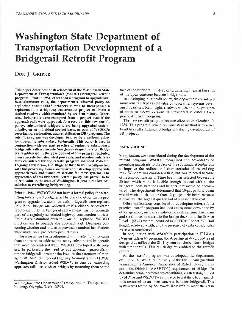
TRANSPORTATION RESEARCH RECORD 1198 45 Washington State Department of Transportation Development of a Bridgerail Retrofit Program DON J. GRIPNE This paper describes the development of the Washington State Department of Transportation's (WSDOT) bridgerail retrofit program. Prior to 1984, other than a program to upgrade low- base aluminum rails, the department's informal policy on replacing substandard bridgerails was to incorporate a replacement in a highway construction project to obtain a desired roadway width mandated by accident history. Other- wise, bridgerails were exempted from a project even if the approach rails were upgraded. As a result of this new retrofit policy, substandard bridgerails are being upgraded system- atically, on an individual project basis, as part of WSDOT's resurfacing, restoration, and rehabilitation (3R) program. The retrofit program was developed to provide a uniform policy for upgrading substandard bridgerails. This policy is used in conjunction with our past practice of replacing substandard bridgerails with a concrete New Jersey shaped barrier. Bridg- erails addressed in the development of this program included open concrete baluster, steel post rails, and wooden rails. Sys- tems considered for the retrofit program included W-beam, 12-gauge thrie beam, and 10-gauge thrie beam. In conjunction with this program, it was also important to develop appropriate approach rails and transition sections for these systems. The application of this bridgerail retrofit policy has proven to be of real value to the state of Washington. It provides a low-cost solution to retrofitting bridgerailing. Prior to 1984, WSDOT did not have a formal policy for retro- fitting substandard bridgerails. Historically, other than a pro- gram to upgrade low aluminum rails, bridgerails were replaced only if the bridge was widened or if accidents necessitated replacement. Thus, bridgerail replacement was not normally part of a regularly scheduled highway construction project. Even if a substandard bridgerail was not replaced, WSDOT practice was to upgrade the approach rail. Decisions con- cerning whether and how to improve substandard installations were made on a project-by-project basis. The impetus for the development of this retrofit policy came from the need to address the many substandard bridgerails that were encountered when WSDOT developed a 3R proj- ect. In particular, the need to add approach guardrails to timber bridgerails brought the issue to the attention of man- agement. Also, the Federal Highway Administration (FHWA) Washington Division asked WSDOT to consider extending approach rails across short bridges by mounting them to the Washington State Department of Transportation, Transportation Building, Olympia, Wash. 98504. face of the bridgerail, instead of terminating them at the ends of the open concrete baluster bridge rails. In developing the retrofit policy, the department considered numerous rail types and evaluated several rail systems devel- oped by others. Rail height, roadway width, and the presence of curbs or sidewalks were all considered as criteria for a practical retrofit program. The new retrofit program became effective on October 10, 1984. This program provides a consistent method with which to address all substandard bridgerails during development of 3R projects. BACKGROUND Many factors were considered during the development of the retrofit program. WSDOT recognized the advantages of mounting guardrails to the face of the substandard bridgerails to improve the redirectional characteristics of the existing rails. W-beam was considered first, but was rejected because of its limited flexibility. Thrie beam was selected because its 20-inch width made it flexible enough to deal with all the bridgerail configurations and heights that would be encoun- tered. The department determined that 10-gauge thrie beam would work much better than 12-gauge thrie beam because it.provided the highest quality rail at a reasonable cost. Other applications considered in developing criteria for a practical retrofit program included rail systems developed by other agencies, such as a crash-tested system using thrie beam and steel posts mounted to the bridge deck, and the Service Level 1 (SL-1) system identified in NCHRP Report 239. Rail height, roadway width, and the presence of curbs or sidewalks were also considered. In conjunction with WSDOT's participation in FHWA's Demonstration 64 program, the department developed a rail design that utilized the SL-1 system on timber deck bridges with timber rails. This rail design was added to the retrofit program. As the retrofit program was developed, the department evaluated the structural integrity of the thrie beam guardrail in meeting the American Association of State Highway Trans- portation Officials (AASHTO's) requirement of 10 kips. To determine actual performance capabilities, crash testing funded by FHW A and WSDOT was initiated to test thrie beam guard- rails mounted to an open concrete baluster bridgerail. This system was tested by Southwest Research to meet the crash
Transcript of Washington State Department of Transportation...
TRANSPORTATION RESEARCH RECORD 1198 45
Washington State Department of Transportation Development of a Bridgerail Retrofit Program
DON J. GRIPNE
This paper describes the development of the Washington State Department of Transportation's (WSDOT) bridgerail retrofit program. Prior to 1984, other than a program to upgrade lowbase aluminum rails, the department's informal policy on replacing substandard bridgerails was to incorporate a replacement in a highway construction project to obtain a desired roadway width mandated by accident history. Otherwise, bridgerails were exempted from a project even if the approach rails were upgraded. As a result of this new retrofit policy, substandard bridgerails are being upgraded systematically, on an individual project basis, as part of WSDOT's resurfacing, restoration, and rehabilitation (3R) program. The retrofit program was developed to provide a uniform policy for upgrading substandard bridgerails. This policy is used in conjunction with our past practice of replacing substandard bridgerails with a concrete New Jersey shaped barrier. Bridgerails addressed in the development of this program included open concrete baluster, steel post rails, and wooden rails. Systems considered for the retrofit program included W-beam, 12-gauge thrie beam, and 10-gauge thrie beam. In conjunction with this program, it was also important to develop appropriate approach rails and transition sections for these systems. The application of this bridgerail retrofit policy has proven to be of real value to the state of Washington. It provides a low-cost solution to retrofitting bridgerailing.
Prior to 1984, WSDOT did not have a formal policy for retrofitting substandard bridgerails. Historically, other than a program to upgrade low aluminum rails, bridgerails were replaced only if the bridge was widened or if accidents necessitated replacement. Thus, bridgerail replacement was not normally part of a regularly scheduled highway construction project. Even if a substandard bridgerail was not replaced, WSDOT practice was to upgrade the approach rail. Decisions concerning whether and how to improve substandard installations were made on a project-by-project basis.
The impetus for the development of this retrofit policy came from the need to address the many substandard bridgerails that were encountered when WSDOT developed a 3R project. In particular, the need to add approach guardrails to timber bridgerails brought the issue to the attention of management. Also, the Federal Highway Administration (FHWA) Washington Division asked WSDOT to consider extending approach rails across short bridges by mounting them to the
Washington State Department of Transportation, Transportation Building, Olympia, Wash. 98504.
face of the bridgerail, instead of terminating them at the ends of the open concrete baluster bridge rails.
In developing the retrofit policy, the department considered numerous rail types and evaluated several rail systems developed by others. Rail height, roadway width, and the presence of curbs or sidewalks were all considered as criteria for a practical retrofit program.
The new retrofit program became effective on October 10, 1984. This program provides a consistent method with which to address all substandard bridgerails during development of 3R projects.
BACKGROUND
Many factors were considered during the development of the retrofit program. WSDOT recognized the advantages of mounting guardrails to the face of the substandard bridgerails to improve the redirectional characteristics of the existing rails. W-beam was considered first, but was rejected because of its limited flexibility. Thrie beam was selected because its 20-inch width made it flexible enough to deal with all the bridgerail configurations and heights that would be encountered. The department determined that 10-gauge thrie beam would work much better than 12-gauge thrie beam because it.provided the highest quality rail at a reasonable cost.
Other applications considered in developing criteria for a practical retrofit program included rail systems developed by other agencies, such as a crash-tested system using thrie beam and steel posts mounted to the bridge deck, and the Service Level 1 (SL-1) system identified in NCHRP Report 239. Rail height, roadway width, and the presence of curbs or sidewalks were also considered.
In conjunction with WSDOT's participation in FHW A's Demonstration 64 program, the department developed a rail design that utilized the SL-1 system on timber deck bridges with timber rails. This rail design was added to the retrofit program.
As the retrofit program was developed, the department evaluated the structural integrity of the thrie beam guardrail in meeting the American Association of State Highway Transportation Officials (AASHTO's) requirement of 10 kips. To determine actual performance capabilities, crash testing funded by FHW A and WSDOT was initiated to test thrie beam guardrails mounted to an open concrete baluster bridgerail. This system was tested by Southwest Research to meet the crash

Treated timber blockout with vertical groin <Thrie Beam blocked out to curb line) nominal dimensions S4S 8" x 8" x 1'-10" ----~ Thrie Beam
Guardrail C10 Go.>
E 0 ..
aJ .. ·c .s::. t-
--~
Drill 1'4" DIA Holes <TYP>
NOTE Locate holes at least 2" from edge of baluster, spacing 6'-3" MAX
0" void CTYP>
E 0 Q)
aJ
.!! ... .s::. t-~
Top of ---~ Roadway
See Backing Plate Detail
TYPICAL BALUSTER RAIL SECTION ELEVATION OF BALUSTER
1 ·s )( 3'-6" a T each baluster post 1Yl6 " DIA hole
~ It) ·u; .. .:.< 0 I/)
C3 ,,; I) I ..., .. 0
b ~ c: 0 ()
1Vz" CLR
3 •4 a 3'-0" Weld to existing deck steel
TYPICAL BALUSTER RAIL SECTION REINFORCING
MARK 1 2 3 4 5
FIGURE I Concrete baluster retrofit with thrie beam.
for%" DIA bolt CTYP>
1"~ l-2" r-
Plate 1/4" AASHTO M 183
BACKING PLATE DETAIL
TRAFFIC BARRIER BAR LIST All reinforcing shell be MSHTO M 31 <Gr. 40>
BENDING DIAGRAM LOCATION SIZE LENGTH (AJI dimensions are out l o
Baluster Vertical 5 3'-6 " Str.I ~ out>
Baluster Too Lonait 5 Cal Str . I -----i--11 Curb to Slab Vert. 4 1'•9" ul ~ E of
Curb Horiz. 4 2'-31/, " 1
' Roodway
Curb Lonait. 4 (a) Str. I -0
.. ,;;::
Ca> Continuous with 2'-0" MIN splice w; ....,J._
~
I 2'•QU I
~I 0
Gripne
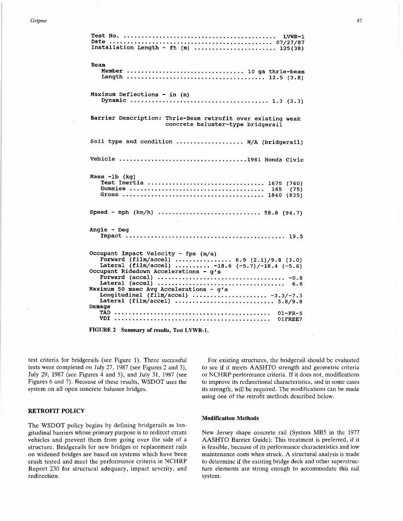
Test No. • . • . . . . • • • . . . . . . . • • . • • . • • . • • • • • • . • • • . . • . . • • LVWR-1 Date ••..••••••..•..•••.••••••••••••••••••••••.•.•. 07/27/87 Installation Length - ft (m) ••••.••••••.•.•......•• 125 (38)
Beam Member • • • . . • . . . . • . . . . . . . . . . • . . . • • • . . • • • 10 ga thrie-beam Length .••.•••.•.•••..............•..•.•...•.. 12.5 (3.8)
Maximum Deflections - in (m) Dynamic • • • . . . • . . . . • . . • . • • • • • • • . . • • . . . . . . . . . . . • 1. 3 ( 3 • 3 )
Barrier Description: Thrie-Beam retrofit over existing weak concrete baluster-type bridgerail
Soil type and condition ••••••••.•••••..•.. N/A (bridgerail)
Vehicle .•••..•..•........•••••.••• , •••..••. 1981 Honda civic
Mass -lb (kg) Test Inertia ..•..•.........•..••...•.•.•••... Dummies ..••..•.•..•..•.•....•.•••••••.......• Gross .••.•••.•..•..••..••.••••.•••••••..•..••
1675 (760) 165 (75)
1840 (835)
Speed - mph (km/h) ............................. 58. 8 (94. 7)
Angle - Deg Impact • . • . • . • • • • . . . . • . . • • • • • • • . . . . . . . • • • • . . . . . . . • . . 19. 5
Occupant Impact Velocity - fps (m/s) Forward (film/accel) •.......••..••.. 6.9 (2.1)/9.8 (3.0) Lateral (film/accel) •.....•••• -18.6 (-5.7)/-18.4 (-5.6)
Occupant Ridedown Accelerations - g's Forward ( accel) . • • . . . • • . • • • . . . . . • • • . • • . • . . . . . . . . . . • -o. 8 Lateral ( accel) . . • . . . • . . . . . . • . . . • . . . . • . • . . . . . • . • . • • 6. 6
Maximum 50 msec Avg Accelerations - g's Longitudinal (film/accel) .•••...••............ -3.3/-7.3 Lateral (film/accel) •..•••.••••.........•.....•. 5.8/9.8
Damage TAD •• , .••.••••...•..•.•••. , . , • . • • • . . . • • . . . . . . . . 01-FR-5 VDI • • • • • . • . . • • • • • • • • • . . . . • . • • • • • . . . . . . . . . . • • . . . 01FREE7
FIGURE 2 Summary of results, Test LVWR·l.
47
test criteria for bridgerails (see Figure 1). Three successful tests were completed on July 27, 1987 (see Figures 2 and 3) , July 29, 1987 (see Figures 4 and 5) , and July 31, 1987 (see Figures 6 and 7). Because of these results, WSDOT uses the system on all open concrete baluster bridges.
For existing structures , the bridgerail should be evaluated to see if it meets AASHTO strength and geometric criteria or NCHRP performance criteria. If it does not , modifications to improve its redirectional characteristics, and in some cases its strength, will be required. The modifications can be made using one of the retrofit methods described below.
RETROFIT POLICY
The WSDOT policy begins by defining bridgerails as longitudinal barriers whose primary purpose is to redirect errant vehicles and prevent them from going over the side of a structure. Bridgerails for new bridges or replacement rails on widened bridges are based on systems which have been crash tested and meet the performance criteria in NCHRP Report 230 for structural adequacy, impact severity, and redirection.
Modification Methods
New Jersey shape concrete rail (System MB5 in the 1977 AASHTO Barrier Guide) : This treatment is preferred, if it is feasible , because of its performance characteristics and low maintenance costs when struck. A structural analysis is made to determine if the existing bridge deck and other superstructure elements are strong enough to accommodate this rail system.

180 ft.
FIGURE 3 Test L VWR-1.
Test No, . . . • . . . . . . . . . . . . . . . . . . . . . . . . . . . . . . . . . . . • . . . LVWR-2 Date . . . . . . . . . . . • . . . . . . . . . . . . . . . . . . . . . . . . . . . . . . . . . . 07 /29/8 7 Installation Length - ft (m) ....................... 125(38)
Beam Member . . . . • . . . . . . • . . . . . . . • . . . • . . • . . . . . . 10 ga thrie-beam Length . . • . • . . . . . . . . . . . . . • . • . . • • . • . . . • . . . • . . . . 12 . 5 ( 3 . ·8 )
Maximum Deflections - in (m) Dynamic • . . • . . . . . . . . . . . . • . . . . . • . . . . . • . . . . . . . . . . 2 . o ( 5 . 1)
Barrier Description: Thrie-Beam retrofit over existing weak concrete baluster-type bridgerail
Soil type and condition .......•..••.•..... N/A (bridgerail)
Vehicle . . . . . • . . . . . . . . . . . . . . . . . . . . . . . . • . . . . . . . . . . 1978 Dodge
Mass -lb (kg) Test Inertia ..................•............. Dummies •.•...... .. .......................... Gross ....... ......... .....•.. ••.•..••..•.••.
4395 (1993) 330 (150)
4725 (2143)
Speed - mph (km/h) ............................. 60. 7 (97. 7)
Angle - Deg Impact • . • . • . . . . . . • . . . . . . . • . . . • . . . . . . . . • . • . . . . . . . . . . 15. 6
Occupant Impact Velocity - fps (m/s) Forward (film) ........•...•....•.....•.....•. 13.9 (4.2) Lateral (film) ............................. -18.3 (-5.6)
Occupant Ridedown Accelerations - g's Forward (film) . . . . . • . . . . . . • . . . . . . . . . . . . . . . . . . . . . . . . -5. 9 __ ...._ ____ ... ,~..!-. __ , ~ 1
J.JCl'-t::.1.a.L \ L.J....LlllJ • • .... • • • • • • • • • • • • • • • • • • • • • • • • • • • • • • • • • .J • ..L.
Maximum 50 msec Avg Accelerations - g's Longitudinal (film) ................................ -5.1 Lateral (film) . . . . . . . . . . . . . . . . . . . . . . . . . . . . • . . . . . . . . 5. 4
Damage TAD .......• .. • , . . . . . . . . . . . . . . . . . . . . . . . . . . . . . . . • 01-FR-5 VDI . . . • . . . . . . . . . . . . . . . . . . . . . . . . . • • . . . . • . . . . • . . • 01FREE7
FIGURE 4 Summary of results, Test L VWR-2.

11.5 ft .
865 ft.
FIGURE 5 Test L VWR-2.
Test No. • . . • • • . . • • . . . . . . . . . . . . . . . . . • . . . . . . . . • . . . . • . LVWR-3 Date •.•••.•...••...........•.....•................ 07/31/87 Installation Length - ft (m) .....•...........•..... 125(38)
Beam Member . • . . . . . . . . . . . • . . . . . • . . . . . . . . . . . . . 10 ga thrie-beam Length . . • . . . . . . . . . . . . . . . . • . . . • . . . . . . . . . . . • . . • 12. 5 ( 3 . 8)
Maximum Deflections - in (m) Dynamic ..••..•..........•..................... 2. 6 (6. 6)
Barrier Description: Thrie-Beam retrofit over existing weak concrete baluster-type bridgerail
Soil type and condition .............•..... N/A (bridgerail)
Vehicle ...•.•.......•.....• 1983 Chevrolet C-10 Pickup truck
Mass -lb (kg) Test Inertia •............................•.. 5070 (2299) Dummies . . . . . . . . . . . . . . . . . . • • . . . . . . . . . . . . . . . . . 330 (150) Gross •.......•..•..........•.•........•....• 5400 (2449)
Speed -mph (km/h) ............................ 66.3 (106.7)
Angle - Deg Impact . • . . • . . . . . • . . . . . . . . . . . . . . . . . . . . . . . • . . . . . . . . . . 19. 4
Occupant Impact Velocity - fps (m/s) Forward (film) . . • • • . . . . • . . . . . . • . . . • . . . . . . . . . 10.6 (3.2) Lateral (film) ............................. -18.4 (-5.6)
Occupant Ridedown Accelerations - g's Forward (film) ....•.............•.•................ -1. 3 Lateral (film) • • • • • . . . . . . . . . . • . . . . . . . • . • . . . . . . . . . . . 5.2
Maximum 50 msec Avg Accelerations - g's Longitudinal (film) ....................•........... -4.0 Lateral (film) . . . . . . . . • . . . • . . . . . . • . . . . . . . • . • . . . . . . . 5. 2
Damage TAD ....•.....•....... , . • . . . . . . . • . . . . . • . . . . . . . . . 01-FR-6 VDI ....•.•.................••.....•.. , •.. , . . . . . 01FREE8
FIGURE 6 Summary of results, Test LVWR-3.

50
_, ..... 0 9 (()
{ 8
305 ft.
FIGURE 7 Test LVWR-3.
Thrie Beam Mounted to Steel Posts
Placing thrie beam mounted to steel posts flush against the face of the curb is also an accepted system and is considered an appropriate treatment when New Jersey shape barriers are not feasible (see Figure 8) . This is a crash-tested system and can be used under the following conditions:
• The bridge is as wide as or wider than the approach roadway, and the curb is wider than 12 inches.
• The bridge width is narrower than the approach roadway , and the curb is 12 to 18 inches wide.
• The bridge has a concrete deck and inadequate steel or wood posts for the bridgerail.
• The width of an approach bridge to a steel truss bridge is narrower than the approach roadway.
The height of the thrie beam should be 2 feet 8 inches measured from the top of the roadway.
A structural analysis is needed to determine if the existing bridge deck and other superstructure elements are strong enough to accommodate this rail system.
Service Level 1 (SL-1)
When the existing bridge cannot accommodate either of the systems described above, an SL-1 system may be used (see
..
.,
W6 x 15 ~ 8'-4" Post spacing
FIGURE 8 Thrie beam mounted to steel posts.
8
B
TRANSPORTATION RESEARCH RECORD 1198
7 6 5 4 3 2 I Ml 8 8 g
Figure 9). Examples of circumstances where this system may be used are bridges with timber decks or bridges with concrete decks in locations where an adequate stiff post transition cannot be installed. WSDOT's bridge engineer is consulted for the information required to complete the bracket design so the SL-1 system can be used.
In all cases, the curb is removed from the bridge for SL-1 type rail installations. This is necessary for proper performance of this rail system and is consistent with crash-tested systems.
Existing rigid concrete rail systems that do not meet the redirectional criteria (e.g., concrete balusters, bridgerails where the face is not smooth) should also be upgraded. Based on performance history, these rails provide adequate strength for vehicle containment but can produce snagging. However, the following are recommended alternatives to improve the redirectional characteristics of the bridgerail:
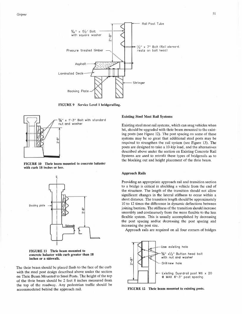
• Bridgerail with curb 18 inches or less: The thrie beams should be carried across the structure and blocked out flush with the face of the curb (see Figure 10). The preferred height of the top of the thrie beam is 2 feet 8 inches measured from the top of the roadway. When this height cannot be obtained, the beam should be installed so that the height of the top of the thrie beam is no lower than 2 feet 3 inches or the height of the bottom of the thrie beam is no higher than 1 foot 3 inches. These measurements are made from the top of the roadway.
• Bridgerail with a curb or sidewalk wider than 18 inches where the approach roadway shoulders are not carried across the structure: The thrie beam should be carried across the structure mounted flush to the face of the bridgerail (see Figure 11). The preferred height of the top of the thrie beam is 2 feet 8 inches measured from the top of the curb or sidewaik. when this height cannot be obtained, the beam should be installed so that the height of the top of the thrie beam is no lower than 2 feet 3 inches or the height of the bottom of the thrie beam is no higher than 1 foot 3 inches . These measurements are made from the top of the curb and sidewalk.
• Bridgerail with a curb wider than 18 inches where the approach roadway shoulders are carried across the structure:
Gripne
o/i6" x 1'/2" Bolt with square washer co
t
N
Presure treated timber ~
Laminated Deck
FIGURE 9 Service Level 1 bridgerailing.
%" x 1'-3" Bolt with standard nut and washer
FIGURE 10 Thrie beam mounted to concrete baluster with curb 18 inches or less.
Bocking plate
't. I
FIGURE 11 Thrie beam mounted to concrete baluster with curb greater than 18 inches or a sidewalk.
The thrie beam should be placed flush to the face of the curb with the steel post design described above under the section on Thrie Beam Mounted to Steel Posts. The height of the top of the thrie beam should be 2 feet 8 inches measured from the top of the roadway. Any pedestrian traffic should be accommodated behind the approach rail.
Rail Post Tube
,._ /"2" x 7" Bolt <Rail element rests on bolt head)
Stringer
Existing Steel Most Rail Systems
51
Existing steel most rail systems, which can snag vehicles when hit, should be upgraded with thrie beam mounted to the existing posts (see Figure 12). The post spacing on some of these systems may be so great that additional steel posts may be required to strengthen the rail system (see Figure 13). The posts are designed to take a 10-kip load, and the alternatives described above under the section on Existing Concrete Rail Systems are used to retrofit these types of bridgerails as to the blocking out and height placement of the thrie beam.
Approach Rails
Providing an appropriate approach rail and transition section to a bridge is critical in shielding a vehicle from the end of the structure. The length of the transition should not allow significant changes in the lateral stiffness to occur within a short distance. The transition length should be approximately 10 to 12 times the difference in dynamic deflections between joining barriers. The stiffness of the transition should increase smoothly and continuously from the more flexible to the less flexible system. This is usually accomplished by decreasing the post spacing and/or decreasing the post spacing and increasing the post size.
Approach rails are required on all four corners of bridges
00 '
N
existing hole
%" x/"2" Button head bolt with nut and washet
I'- Drill new hole
I r- Existing Guardrail post W6 x 20 I I!:! MAX 6'-3" post spacing
.__ _ _._ __ ............ J
FIGURE 12 Thrie beam mounted to existing posts.

52
New W6 x 20 l!l 6' - 3" MAX post spacing
1" DIA ASTM 307 --
Block up with as required to
TRANSPORTATION RESEARCH RECORD 1198
ixJ I
"4
Recessed plate flush & perpendicu lar to bolt axis
2 - 1" Self-drilling phillips red head or approved equal
FIGURE 13 Thrie beam mounted to existing posts with new posts placed between existing posts.
Rigid Object
FIGURE 14 Type 1 transition section.
timber posts
6" x 8" or 8" x 8" Treated timber post <TYPl 6'-3" Spacing <TY.Pl
\. Neutral a)(is
[fE3--~--E3------~ .,~,
FIGURE 15 Design F terminal section.
carrying two-way traffic and on both corners of the approach end for one-way traffic. The following criteria should be used for the bridgerails that will be encountered.
For rigid concrete bridge rail systems that meet the strength and performance criteria and do not need to be retrofitted, a Type 1 transition section (System Tl in the 1977 AASHTO Barrier Guide) is used (see Figure 14). The following is recommended for aligning and connecting a W-beam approach guardrail to the bridgerail.
TOP VIEW
SIDE VIEW
• Bridgerail with no curb: The approach guardrail should be lined up with the face of the bridgerail and connected to the bridge rail with a Design F terminal section (see Figure 15).
• Bridgerail with curb 18 inches or less: The approach guardrail should be lined up with the face of the curb, blocked out from the bridgerail, and connected to the bridgerail using a Design F terminal section.
• Bridgerail with a curb or sidewalk wider than 18 inches:
Gripne 53
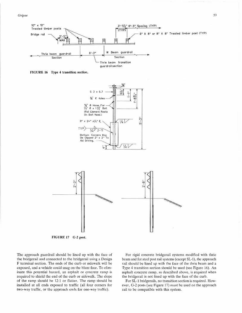
10" x 10" 3'-1Y2" 6'-3" Spacing CTYPl Treated timber posts ~ fi?i1•<TYP~~1 ...._ 6" X 8" or 8'~ X 8" Treated timber post CTYPl
Bridge rail ~~-S" MAX X rxl
~l =====:!======~==n===========t
Thrie beam uardroil W Beam guardrail
Section Section
Thrie beam transition guardrail section
FIGURE 16 Type 4 transition section.
FIGURE 17 G-2 post.
The approach guardrail should be lined up with the face of the bridgerail and connected to the bridgerail using a Design F terminal section. The ends of the curb or sidewalk will be exposed, and a vehicle could snag on the blunt face. To eliminate this potential hazard, an asphalt or concrete ramp is required to shield the end of the curb or sidewalk . The slope of the ramp should be 12:1 or flatter. The ramp should be installed at all ends exposed to traffic (all four corners for two-way traffic, or the approach ends for one-way traffic).
·~ --~ •
For rigid concrete bridgerail systems modified with thrie beam and for steel post rail systems (except SL-1), the approach rail should be lined up with the face of the thrie beam and a Type 4 transition section should be used (see Figure 16) . An asphalt concrete ramp, as described above , is required when the bridgerail is not lined up with the face of the curb.
For SL-1 bridgerails, no transition section is required . However, G-2 posts (see Figure 17) must be used on the approach rail to be compatible with this system.

54
COSTS
The bids WSDOT has received for mounting thrie beams to concrete baluster bridgerails or rails with existing steel posts range from $14 to $42 per foot. Over 16,000 feet of thrie beam have been installed on concrete baluster bridgerails. The average cost is $21.60. Where extra steel posts are required, the cost for adding each one is about $100. The cost for installing a SL-1 system on a timber rail bridge is about $80 to $85 per foot. This includes the cost of removing the existing timber rail.
IMPLEMENTATION AND CONCLUSIONS
The WSDOT retrofit applications are intended to be simple to install, requiring standard 12 feet 6 inch thrie beams to
TRANSPORT AT/ON RESEARCH RECORD 1198
keep costs down and repairs easy. To date , WSDOT has had 21 contracts that provided retrofits for 31 bridges , using thrie beams or W-beams. (Early WSDOT direction was to use W-beams under certain conditions.) Three bridges received the SL-1 system under the FHW A Demonstration 64 program.
On four other bridges , the SL-1 system was installed during 3R or safety projects .
The application of this bridgerail retrofit policy has proven to be of real value to the state of Washington and has received the full support of management and of the FHWA Washington Division . It provides a low-cost answer for retrofitting bridgerailing.