Washer, Electrical Equipment Bond WEEB - Kinetic...
12
3098177 Products are tested to UL 467, CAN/CSA-C22.2 No. 41 US/Canadian standards for safety grounding and bonding equipment Washer, Electrical Equipment Bond WEEB Patent Pending INSTALLATION INSTRUCTIONS For Kinetic Solar K-Rack only Please read carefully before installing. Wiley Electronics recommends that the sufficient details of the installation be submitted to the AHJ for approval before any work is started. WEEB-KSR WEEB-Lug 6.7 Document Number 104-0404-000075-000 Wiley Electronics LLC. 2006-2011 - All Rights Reserved Page 1 of 12
Transcript of Washer, Electrical Equipment Bond WEEB - Kinetic...

3098177
Products are tested to UL 467, CAN/CSA-C22.2 No. 41US/Canadian standards for safety grounding and bonding equipment
Washer, Electrical Equipment Bond
WEEBPatent Pending
INSTALLATION INSTRUCTIONSFor Kinetic Solar K-Rack only
Please read carefully before installing.Wiley Electronics recommends that the sufficient details of the
installation be submitted to the AHJ for approval before any workis started.
WEEB-KSR WEEB-Lug 6.7
Document Number 104-0404-000075-000Wiley Electronics LLC. 2006-2011 - All Rights Reserved
Page 1 of 12

WEEB COMPATIBILITY
Standard Top Down Clamps
The WEEBs used for bonding the PV modules to the mounting rails are compatible with various cross-sections of module frames. The following are examples of module frames that are compatible. Notice that the WEEB teeth are positioned completely under the edge of the module frame.
OK OK
The WEEB family of products can be used to bond anodized aluminum, galvanized steel, steel and other electrically conductive metal structures.All installations shall be in accordance with NEC requirements in the USA and with CSA C22.1 in Canada. The WEEBs are for use with modules that have a maximum series fuse rating of less than 25A.
X
OK
The following is an example of a module frame that is incompatible withthe WEEB. The WEEB teeth are positioned only partially under the edgeof the module due to the lip on the top edge of the module frame.
Document Number 104-0404-000075-000Wiley Electronics LLC. 2006-2011 - All Rights Reserved
Page 2 of 12

Document Number 104-0404-000075-000Wiley Electronics LLC. 2006-2011 - All Rights Reserved
Page 3 of 12
Shown here is an example of a lip that will prevent the WEEB teeth from properly penetrating the module frame. This type of frame is not compatible with the WEEB.
Shown here is an example of a groove that will prevent the WEEB teeth from properly penetrating the module frame. This type of frame is not compatible with the WEEB.
WEEB COMPATIBILITYModule frames like those shown here may have a ridge or lip on the bottom edge of the frame that would prevent the WEEB teeth from fully embedding.
Important Note:Inspect each module frame used with a WEEB to ensure that the bottom mounting face of the frame is flat, and that there are no hinderances to embedding WEEB teeth. Do not use a module with a frame that prevents the WEEB teeth from embedding fully.
X
X

NO LESS THAN 3mmNO GREATER THAN 8.5mm
NO THINNERTHAN 1.5mm
WEEB-KSR on Boxed Module FramesCertain module frames do not have enough structural strength to withstand the force required to embed a WEEB. These frames will deform and therefore not allow sufficient penetration of the WEEB teeth. The general requirements for minimum module frame thickness of "boxed" type module frames are illustrated below.
OK
Document Number 104-0404-000075-000Wiley Electronics LLC. 2006-2011 - All Rights Reserved
Page 4 of 12

Grounding Wire
Use a WEEB-KSR to bondsolar modules to module mounting rail.
Document Number 104-0404-000075-000Wiley Electronics LLC. 2006-2011 - All Rights Reserved
Page 5 of 12
Use one WEEB-Lug 6.7 per railto connect to equipment ground
Assemble splice kit with (2) WEEB-KSRs
SYSTEM OVERVIEW
Important notesUse general purpose anti-seize compound on fastener threads 1.when installing WEEBs.The NEC section 690.43 states, "Exposed non-current carrying2.metal parts of module frames, equipment, and conductorenclosures shall be grounded in accordance with 250.134 or250.136(A) regardless of voltage."WEEBs are intended for SINGLE USE ONLY. Functionality will 3.not be guaranteed if reused.
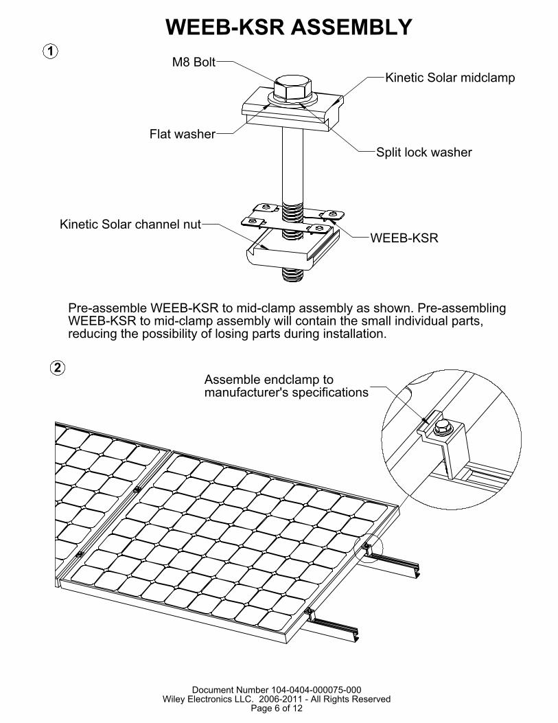
Kinetic Solar midclampM8 Bolt
Split lock washerFlat washer
WEEB-KSRKinetic Solar channel nut
Document Number 104-0404-000075-000Wiley Electronics LLC. 2006-2011 - All Rights Reserved
Page 6 of 12
Assemble endclamp tomanufacturer's specifications
2
WEEB-KSR ASSEMBLY1
Pre-assemble WEEB-KSR to mid-clamp assembly as shown. Pre-assembling WEEB-KSR to mid-clamp assembly will contain the small individual parts, reducing the possibility of losing parts during installation.

Document Number 104-0404-000075-000Wiley Electronics LLC. 2006-2011 - All Rights Reserved
Page 7 of 12
Slightly life solar module andslide WEEB-KSR and midclampassembly under the edge of the modulewhen the midclamp assemly is correctlyinstalled.
Slide pre-assembledWEEB-KSR and midclampassembly into position
3
Important note:To correctly install WEEB-KSR, ensure that both sides of the solar modules are completely positioned against the mid-clamp. Refer to WEEB compatibility page for illustrations. Visually check that WEEBs are properly positioned.
MIDCLAMP ASSEMBLY

When position of solarmodules are finalized,torque fasteners to12ft-lb / 16.3N-m usinggeneral purposeanti-seize compoundon threads.
Document Number 104-0404-000075-000Wiley Electronics LLC. 2006-2011 - All Rights Reserved
Page 8 of 12
Assemble the end clamp tomanufacturer's specification.
4
5
Important note:WEEBs are for SINGLE USE ONLY! Do not torque fasteners down if position of solar modules is not finalized. Only slightly tighten fasteners to keep modules in place.

C X R = 4 X 1WEEB-KSR NEEDED = C X R = 4 X 1 = 4
x
x
x
x
6
C X R = 5 X 1WEEB-KSR NEEDED = [C+1] X R = [5+1] X 1 = 6
x
x
x
x
x
X DENOTES PLACES TO INSTALL WEEB-KSR
WEEB-KSR LAYOUT
EVEN NUMBER OF MODULES IN ROW
ODD NUMBER OF MODULES IN ROW
x
X DENOTES PLACES TO INSTALL WEEB-KSR
Note:When replacing a single faulty module, also remove the adjacent module which contacts the same WEEBs as the faulty module. This will ensure that there are never ungrounded modules in the array.
Document Number 104-0404-000075-000Wiley Electronics LLC. 2006-2011 - All Rights Reserved
Page 9 of 12

WEEB teeth toward rail
Assemble WEEBLug-6.7 assembly and tighten fasteners to 10ft-lb/13.5 N-m, using generalpurpose anti-seize on threads.
Drill bolt clearance holediameter 17/64in / 7mm in the rail to mount the WEEBLug-6.7.
Document Number 104-0404-000075-000Wiley Electronics LLC. 2006-2011 - All Rights Reserved
Page 10 of 12
7
WEEBLUG ASSEMBLY
Important note:
WEEB-6.7 that sits under the WEEBLug is for SINGLE USE1.ONLY! Ensure position is correct before tightening.
2. The WEEBLug-6.7 may be used with a maximum equipmentground wire of 6 AWG.

Lay in equipment groundconductor and torque boltto 7 ft-lb / 10 N-m.
8
GROUND CONDUCTOR ASSEMBLY
Important note:WEEB-6.7 that sits under the WEEBLug is for SINGLE USE 1.ONLY. Ensure position is correct before tightening down.The may be used with a maximum 2.equipment ground wire of 6 AWG.
Document Number 104-0404-000075-000Wiley Electronics LLC. 2006-2011 - All Rights Reserved
Page 11 of 12

Torque fasteners to12 ft-lb / 16.3 N-m usinggeneral purpose anti-seizecompound on threads
Document Number 104-0404-000075-000Wiley Electronics LLC. 2006-2011 - All Rights Reserved
Page 12 of 12
SPLICE KIT ASSEMBLY
9 Use one (1) WEEB-KSR on each side of the splice in order to properly electrically bond the rails.