WARRNAMBOOL CITY COUNCIL · APPROVED DATE STANDARD DRAWING No REV WARRNAMBOOL CITY COUNCIL STANDARD...
52
WARRNAMBOOL CITY COUNCIL Standard Drawings Document History Revision Issued by Date 1 Warrnambool City Council 14/09/10 2 Warrnambool City Council 10/12/10 3 Warrnambool City Council 22/07/11
Transcript of WARRNAMBOOL CITY COUNCIL · APPROVED DATE STANDARD DRAWING No REV WARRNAMBOOL CITY COUNCIL STANDARD...

WARRNAMBOOL CITY COUNCIL
Standard Drawings
Document History
Revision Issued by Date 1 Warrnambool City Council 14/09/10 2 Warrnambool City Council 10/12/10 3 Warrnambool City Council 22/07/11
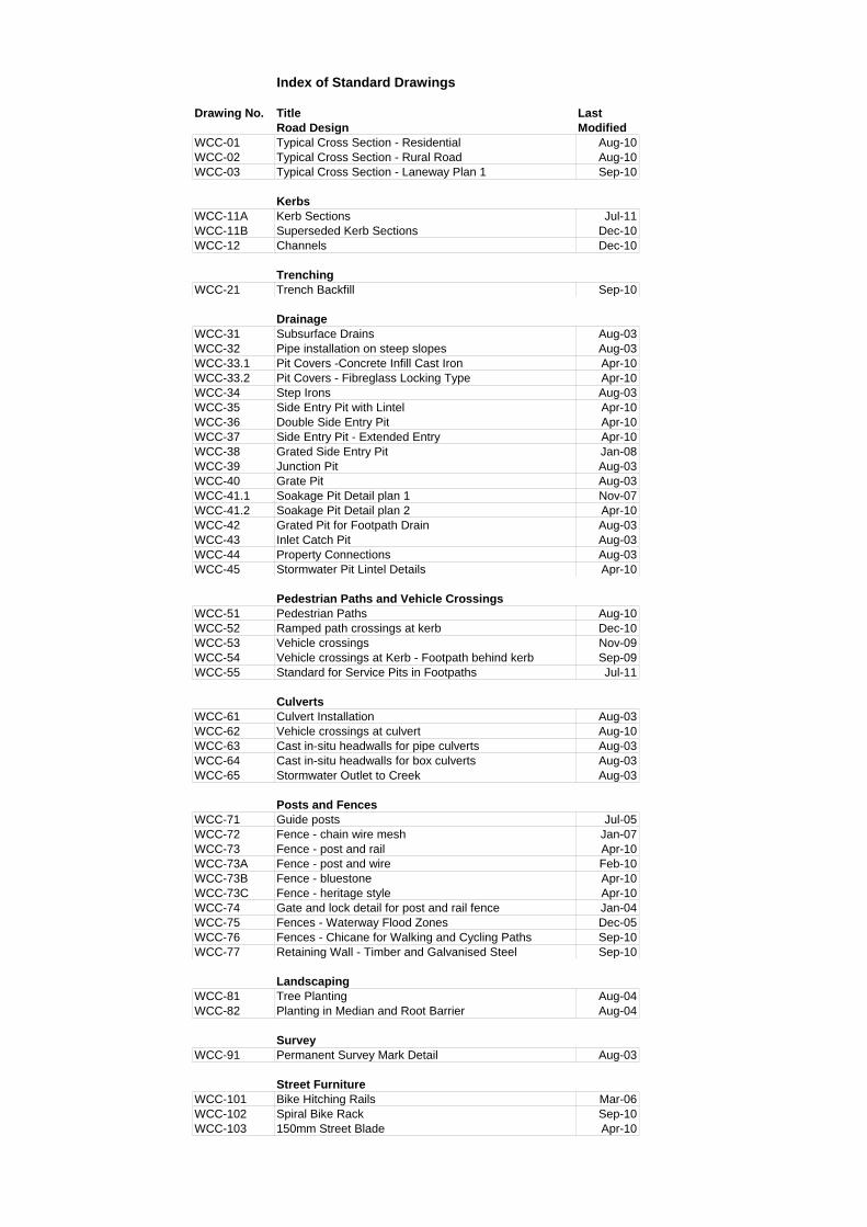
Index of Standard Drawings
Drawing No. Title LastRoad Design Modified
WCC-01 Typical Cross Section - Residential Aug-10WCC-02 Typical Cross Section - Rural Road Aug-10WCC-03 Typical Cross Section - Laneway Plan 1 Sep-10
KerbsWCC-11A Kerb Sections Jul-11WCC-11B Superseded Kerb Sections Dec-10WCC-12 Channels Dec-10
TrenchingWCC-21 Trench Backfill Sep-10
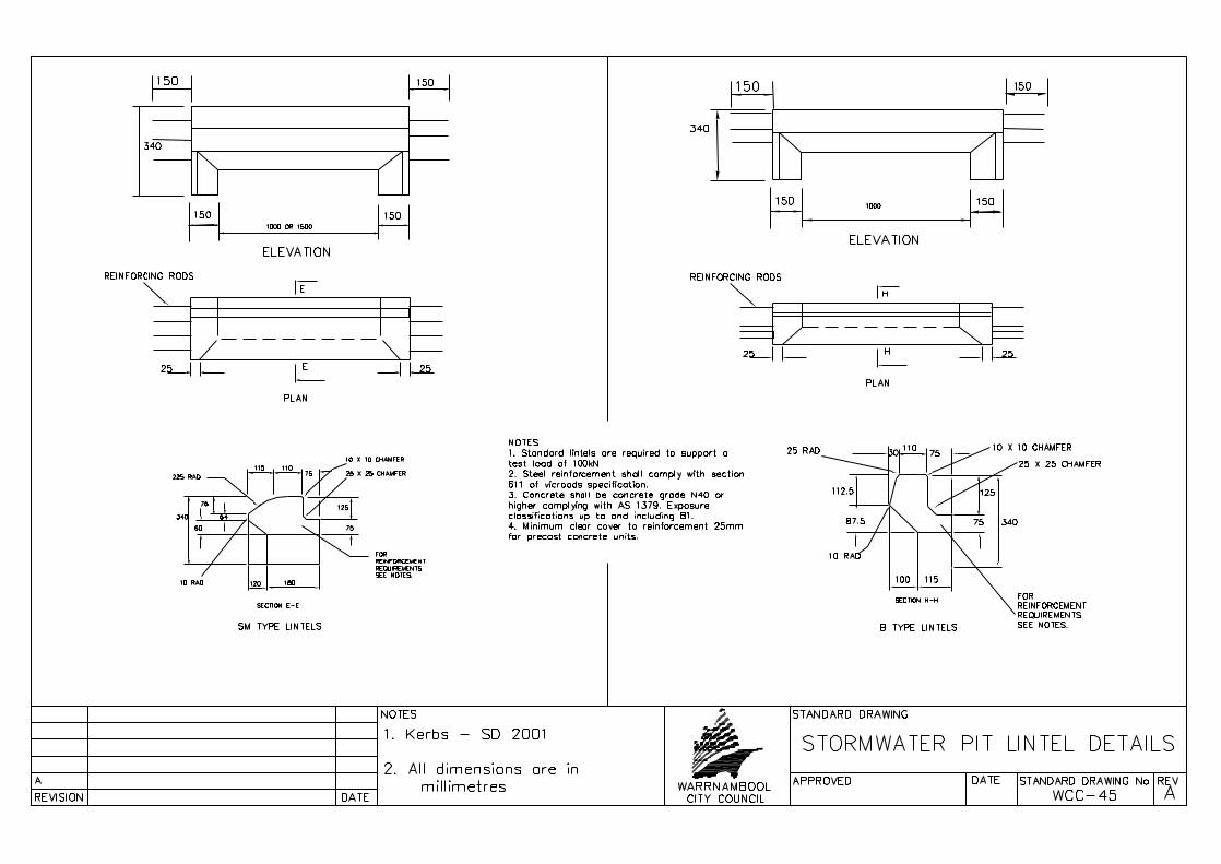
DrainageWCC-31 Subsurface Drains Aug-03WCC-32 Pipe installation on steep slopes Aug-03WCC-33.1 Pit Covers -Concrete Infill Cast Iron Apr-10WCC-33.2 Pit Covers - Fibreglass Locking Type Apr-10WCC-34 Step Irons Aug-03WCC-35 Side Entry Pit with Lintel Apr-10WCC-36 Double Side Entry Pit Apr-10WCC-37 Side Entry Pit - Extended Entry Apr-10WCC-38 Grated Side Entry Pit Jan-08WCC-39 Junction Pit Aug-03WCC-40 Grate Pit Aug-03WCC-41.1 Soakage Pit Detail plan 1 Nov-07WCC-41.2 Soakage Pit Detail plan 2 Apr-10WCC-42 Grated Pit for Footpath Drain Aug-03WCC-43 Inlet Catch Pit Aug-03WCC-44 Property Connections Aug-03WCC-45 Stormwater Pit Lintel Details Apr-10
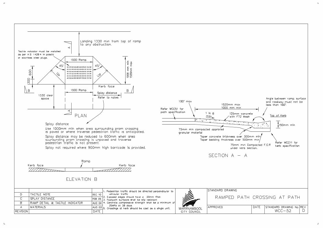
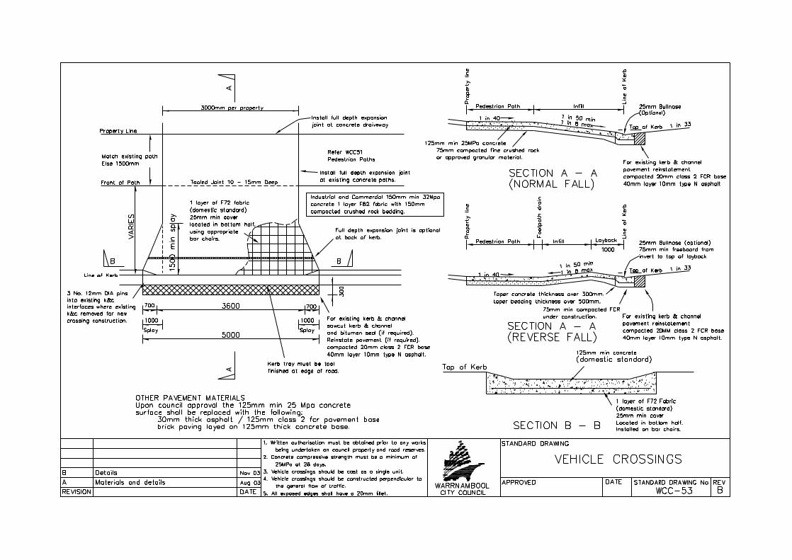
Pedestrian Paths and Vehicle CrossingsWCC-51 Pedestrian Paths Aug-10WCC-52 Ramped path crossings at kerb Dec-10WCC-53 Vehicle crossings Nov-09WCC-54 Vehicle crossings at Kerb - Footpath behind kerb Sep-09WCC-55 Standard for Service Pits in Footpaths Jul-11
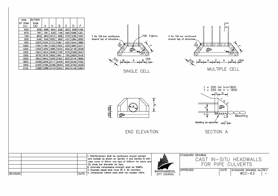
CulvertsWCC-61 Culvert Installation Aug-03WCC-62 Vehicle crossings at culvert Aug-10WCC-63 Cast in-situ headwalls for pipe culverts Aug-03WCC-64 Cast in-situ headwalls for box culverts Aug-03WCC-65 Stormwater Outlet to Creek Aug-03
Posts and FencesWCC-71 Guide posts Jul-05WCC-72 Fence - chain wire mesh Jan-07WCC-73 Fence - post and rail Apr-10WCC-73A Fence - post and wire Feb-10WCC-73B Fence - bluestone Apr-10WCC-73C Fence - heritage style Apr-10WCC-74 Gate and lock detail for post and rail fence Jan-04WCC-75 Fences - Waterway Flood Zones Dec-05WCC-76 Fences - Chicane for Walking and Cycling Paths Sep-10WCC-77 Retaining Wall - Timber and Galvanised Steel Sep-10
LandscapingWCC-81 Tree Planting Aug-04WCC-82 Planting in Median and Root Barrier Aug-04
SurveyWCC-91 Permanent Survey Mark Detail Aug-03
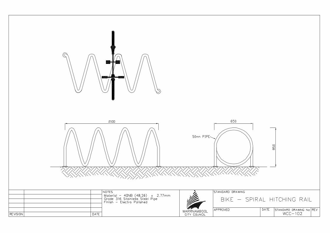
Street FurnitureWCC-101 Bike Hitching Rails Mar-06WCC-102 Spiral Bike Rack Sep-10WCC-103 150mm Street Blade Apr-10


APPROVED DATE STANDARD DRAWING No REVWARRNAMBOOLCITY COUNCILREVISION DATE
STANDARD DRAWING
RURAL ROADTYPICAL CROSS SECTION
WCC-02A SECTION NO. OCT 09
PAVEMENT COMPACTION DETAILSLAYER
BASE
SUB BASE
SUB GRADE
COMPACTION REQUIREMENTS
98% MOD A.A.S.H.O
97% MOD A.A.S.H.O
95% MOD A.A.S.H.O
NOTE: ALL PAVEMENT LAYERS MUST BETESTED IN ACCORDANCE WITH VICROADSSPECIFICATIONS WITH APPROVED A NATAACCREDITATIONSB MAY 10PAVEMENT COMPACTION DETAILS
C
C Aug 10Verge Grade

APPROVED DATE STANDARD DRAWING No REVWARRNAMBOOLCITY COUNCILREVISION DATE
STANDARD DRAWING
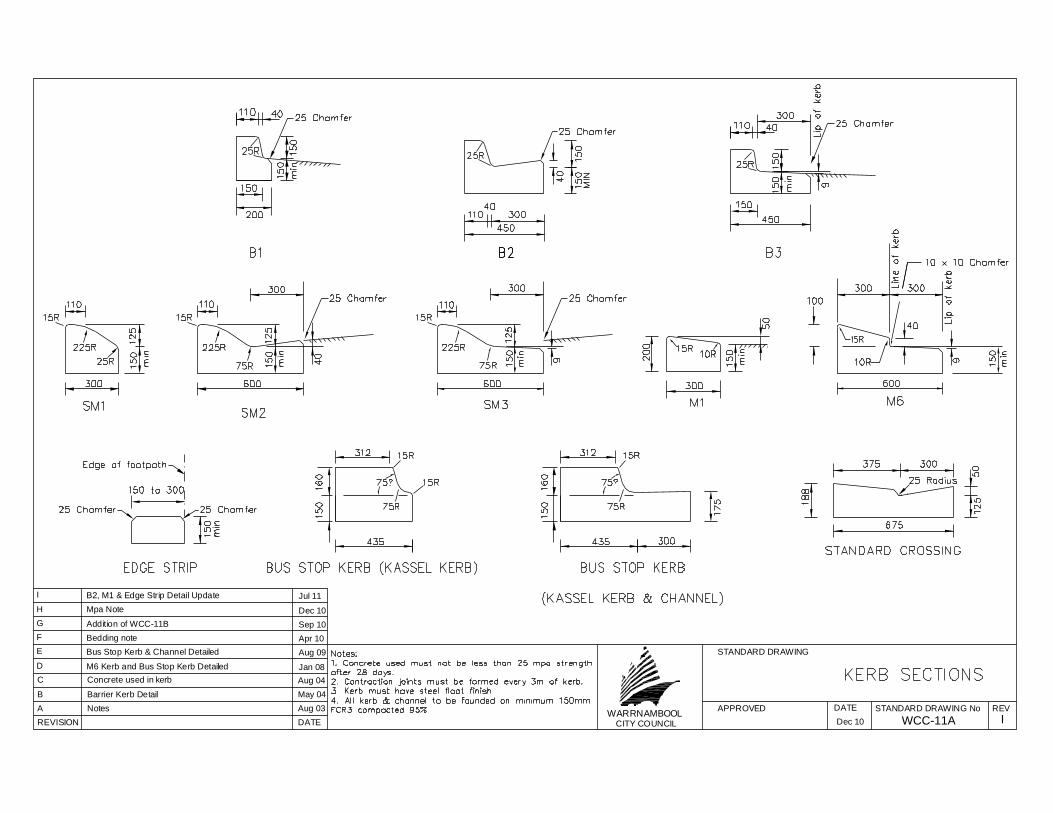
IWCC-11AA Aug 03NotesB May 04Barrier Kerb Detail
C Aug 04Concrete used in kerbD M6 Kerb and Bus Stop Kerb Detailed Jan 08
E Bus Stop Kerb & Channel Detailed Aug 09
F Bedding note Apr 10
G Addition of WCC-11B Sep 10
Dec 10
H Mpa Note Dec 10
I B2, M1 & Edge Strip Detail Update Jul 11

APPROVED DATE STANDARD DRAWING No REVWARRNAMBOOLCITY COUNCIL
STANDARD DRAWING
HWCC-11BREVISION DATEA Aug 03Notes
B May 04Barrier Kerb DetailC Aug 04Concrete used in kerbD M6 Kerb and Bus Stop Kerb Detailed Jan 08
E Bus Stop Kerb & Channel Detailed Aug 09
F Bedding note Apr 10
G Addition of WCC-11B Sep 10
Dec 10
H Mpa Note Dec 10


APPROVED DATE STANDARD DRAWING No REVWARRNAMBOOLCITY COUNCILREVISION DATE
STANDARD DRAWING
F
TRENCHING BACKFILL
WCC-21
C. TRENCHES IN FOOTPATHS
no greater than 150mm.Compaction to be minimum92% modified A.A.S.H.O.
excavation which containsno more than 20% rockfragments (150mm max size)to be compacted in layers
Ordinary earth from
or wheel rolled andapproved topsoil rammed150mm minimum council
B. TRENCHES IN NATURE STRIPS15
0mm
A. TRENCHES IN ROADS15
0 m
in
rammer to 97% modified densityin 150mm layers using vibrating
equivalent material).Class 3 F.C.R. (or approved
modified density ratio.Top (base) compacted to 98%class 2 F.C.R. in 2 X 150mm layers.
varie
s (m
in 1
50 m
m)
150m
m30
0
150m
mm
in
rolled in 150mm layers.backfill rammed orApproved granular
class 3 F.C.R.150mm compacted depth
Lower (sub base) layer compactedto 97% modified density ratio.
ratio.
300mm compacted depth
Backfill and compacted mechanically
seeded.
SURFACINGS
Footpaths
Concrete vehicular crossing
Seal
deep with 1 layer F72 mesh
25 MPa concrete, 125mm deep
Bituminous concrete (hotmix)
DEFECT LIABILITY PERIOD12 months following date of practical completion.A bond of $50 per square metre may be required for someroads openings and footpath openings prior to workscommencing. The bond will be refunded at the expiry ofdefects liability period upon approval by council's officer.
30mm residual roads
varie
s (M
in 1
50 m
m)
150
A Aug 03Notes
40mm collector roads / industrial roads
including F72 mesh.
Cut Wearing surface to form a straight edgeWearing surface
Authority Service zoneIncluding attachmentsand appendagesGranular beddingplastic index less than 3
Authority's Marker TapeAuthority Service zoneIncluding attachmentsand appendagesGranular beddingplastic index less than 3
Authority's Marker Tape
Authority Service zoneIncluding attachmentsand appendagesGranular beddingplastic index less than 3
Authority's Marker Tape
Re-seed and level to match existingSurfacing to match existing See note below
B Nov 03Services, Min cover and notes
varie
s (M
in 1
50 m
m)
Any unsuitable material to beremoved from floor of trench
Any unsuitable material to beremoved from floor of trench Any unsuitable material to be
removed from floor of trench
NotesROAD RESERVE WORKS PERMITA road reserve works permit must be obtained from councilprior to works commencing.A miniumim three working days notice to be given prior tocommencement
COMPACTION AND TESTINGMoisture content shall be adjusted to optimum at time ofcompactionComapction tests are requiered for each layer where density isspecified
Council shall at random do testing and if workmanshipor compaction is below the requirment, the trench willbe rectified by Council and any Expenses incurred indoing so shall be regharged to the contractor
(ii) bituminous concrete (hotmix) 25 mm, 75 mm base
C Seal Detail Notes Oct 06
(i) 25 MPa concrete, 100mm
D Footpath Note Nov 09
(See notes below)
E Code of Practice Note May 10
F B. Trench Note Sep 10
APPROVED DATE STANDARD DRAWING No REVWARRNAMBOOLCITY COUNCILREVISION DATE
STANDARD DRAWING
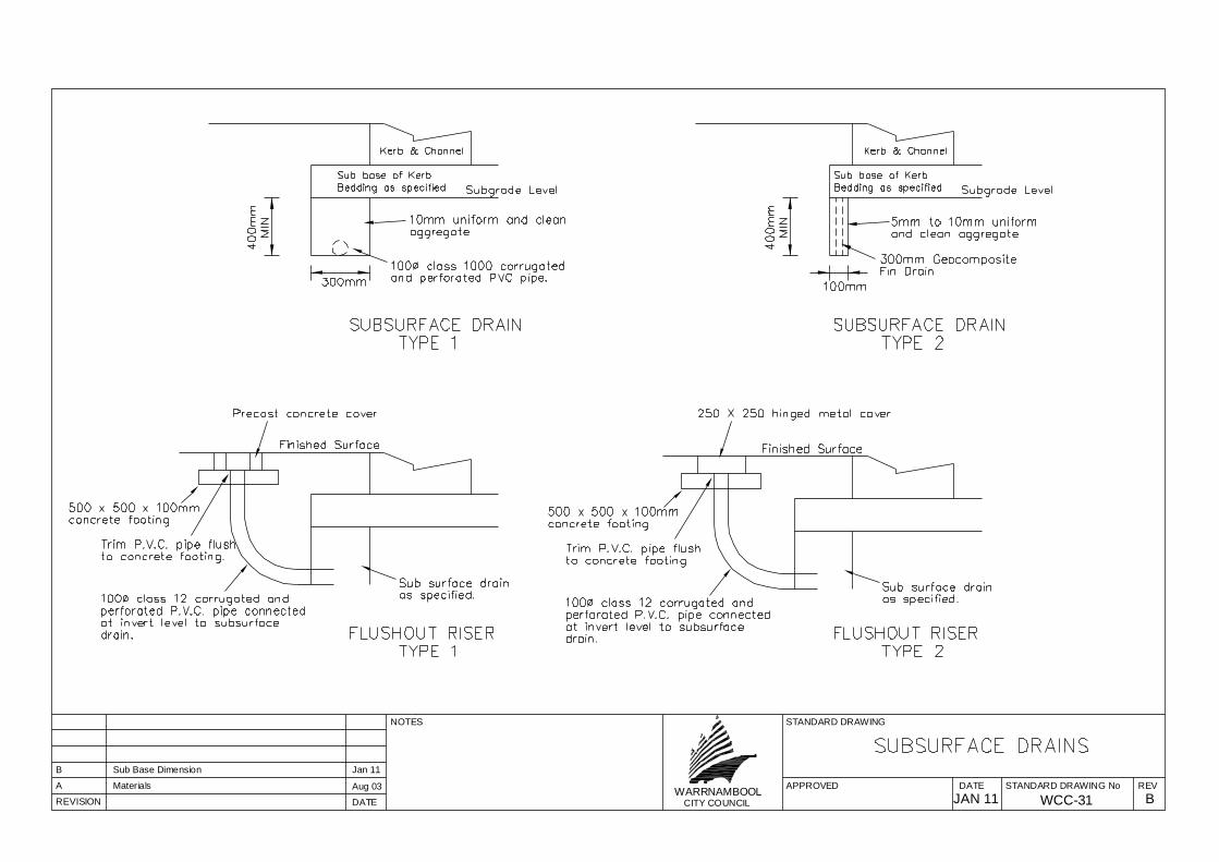
B
NOTES
WCC-31A Aug 03Materials
JAN 11
B Jan 11Sub Base Dimension

WARRNAMBOOLCITY COUNCIL A
NOTES
PIPE INSTALLATION ON STEEP SLOPES
WCC-32
Anchor blocks must be placed at maximum intervals of10 metres when slope of pipe exceeds 1 in 7.Concrete compressive strength must be a minimum of32 MPa at 28 days.
250 min
300
min
150
min
A
A
300 min
Anchor Block
SECTION A - A
APPROVED DATE STANDARD DRAWING No REV
REVISION DATE
STANDARD DRAWING
A Aug 03Notes
id12
5883
28 p
dfM
achi
ne b
y B
road
gun
Sof
twar
e -
a g
reat
PD
F w
riter
! -
a gr
eat P
DF
cre
ator
! - h
ttp://
ww
w.p
dfm
achi
ne.c
om h
ttp://
ww
w.b
road
gun.
com

APPROVED DATE STANDARD DRAWING No REVWARRNAMBOOLCITY COUNCILREVISION DATE
STANDARD DRAWING
-
NOTES
WCC-33 - SHEET 1 OF 2
CONCRETE INFILLED CAST IRON COVER & FRAME
600
Cle
ar O
peni
ng
900 Clear Opening
PIT COVERSCONCRETE INFILLED CAST IRON
LID LOADINGS(i) 210 KN FOR LIDS IN ROAD
PAVEMENT AREAS(i) 150 KN FOR ALL OTHER AREAS
Milnes Gatic cover 301C96D(or equivalent)
A Apr 10Removal o f side entry p it drawing

APPROVED DATE STANDARD DRAWING No REVWARRNAMBOOLCITY COUNCILREVISION DATE
STANDARD DRAWING
-
NOTES
WCC-33 - SHEET 2 OF 2
PIT COVERSFIBREGLASS LOCKING TYPE
Dimensiions given are for 900mm x 600mmjunction pits with 150mm thick walls.FIXING BOLTS ARE LOCATED A MIN.OF50mm FROM FACE (INTERNAL OREXTERNAL) OF PIT WALL.
25mm x 5mm cornersections weldedflush with top.
12mm dia. holescountersunk 4 places
75mm x 50mm x 5 mmgalvanised angle ironframe
Attach with 10mm dia x75mm long Dynabolt orcontinuous thread lug.
Pit wall
FRAME
SECTION A-A
A
SCALE: 1:15
LID
45mm Thick fibreglass pit lid
6mm Recess
All stainless steel lockingmechanism used inconjunction with matchinglifting handle
1100
800
50
785
1085

id12
7641
87 p
dfM
achi
ne b
y B
road
gun
Sof
twar
e -
a g
reat
PD
F w
riter
! -
a gr
eat P
DF
cre
ator
! - h
ttp://
ww
w.p
dfm
achi
ne.c
om h
ttp://
ww
w.b
road
gun.
com


APPROVED DATE STANDARD DRAWING No REVWARRNAMBOOLCITY COUNCILREVISION DATE
STANDARD DRAWING
B
CONVERTED TO GRATE PIT
WCC-38
1. For individual sizes, refer to detail drawings.2. Concrete compressive strength must be a minmimum of 25 MPa at 28 days.3. Pits deeper than 1m shall be provided with step irons. (Refer WCC-34 - Step irons)4. Rectangular precast concrete pits may be used subject to prior aproval and installation to manufacturers specification.
1000 1000
90015 15
PLAN
150 150
Finished surface
R & S grating side entry pitconversion cover weave grate
600
300
Lip of Kerb
Line of Invert
as required (or equivalent).
SECTION
SIDE ENTRY PIT
A NOV 03Pit cover description.B Photograph of pit included. JAN 08
900
Lip o
f Ker
b
Line
of I
nver
t
300 MINIMUM 600

id13
0215
78 p
dfM
achi
ne b
y B
road
gun
Sof
twar
e -
a g
reat
PD
F w
riter
! -
a gr
eat P
DF
cre
ator
! - h
ttp://
ww
w.p
dfm
achi
ne.c
om h
ttp://
ww
w.b
road
gun.
com

id13
0782
18 p
dfM
achi
ne b
y B
road
gun
Sof
twar
e -
a g
reat
PD
F w
riter
! -
a gr
eat P
DF
cre
ator
! - h
ttp://
ww
w.p
dfm
achi
ne.c
om h
ttp://
ww
w.b
road
gun.
com

APPROVED DATE STANDARD DRAWING No REVWARRNAMBOOLCITY COUNCILREVISION DATE
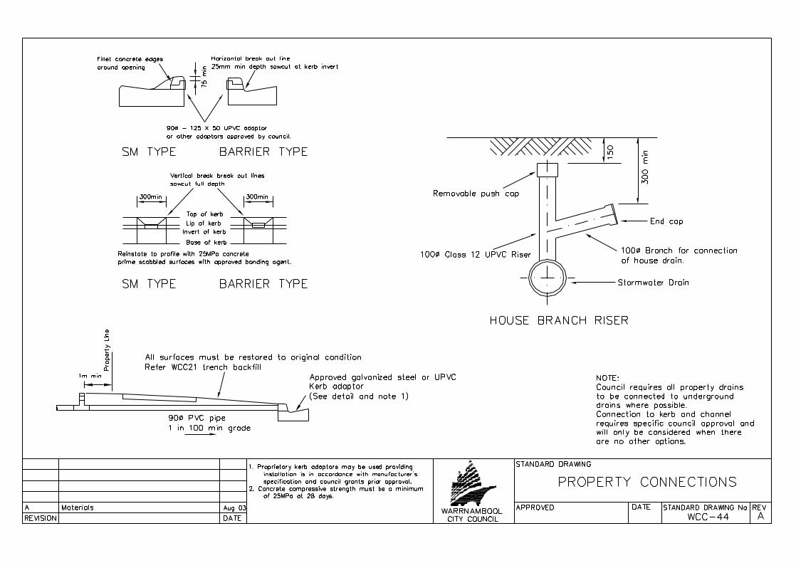
STANDARD DRAWING
C
STANDARD SOAKAGE PIT
Atlantis D-raintank (or equivalent).
PLAN
Tanks to be interlocked togethervertically and fully wrappedwith geotextile fabric 351(or equivalent).Tanks to have the followingperformance criteria:i) Tanks to have a minimum flowrate on 2000 L/Min understatic head.ii) Tanks solid wall area not toexceed 25%.iii) Tanks to be made from recycledplastic materials.
Soak area to be located in a natural or created basin (turkeys nest).The disturbed area to be rolled with hand roller and sown with approvedgrass seed. Created basins must be constructed so they appear natural.
Test holes to be full depth of the proposed soakage pit must be dug todetermined whether the soil is suitable and test carried out by a qualifiedgeotechnical engineer to establish the infiltration rate of the soil beforethe location and depth of pit is finalised.
Minimum soakage pit volume 6.8 cubic metres.
All concrete used on pit to be 32MPa andvibrated into position as per AS3600, Section 19.
All measurements in millimetres.
Step irons to WCC-34.
See sheet 2 for soakage pit sizing design guidelines.
Pit lid and frame to WCC-33.
1.
2.
3.4.
5.
7.8.
6.
PROPEX 4545 GEOTEXTILE(OR EQUIVALENT)
WEEPHOLES
SCALE 1 : 50
INLET PIPE
900
600
PIT LID & FRAME TO WCC-33
L
W
SECTION A-ASCALE 1 : 50
PIT LID & FRAME TO WCC-331 : 5 MAX1 : 40 MIN
SEE NOTE 1
Step irons - Refer WCC34
90mmØ OUTLETS CASTINTO PIT WALLS
VAR
Y AS
REQ
UIR
ED
1800
min
600
495
180180
PROPEX 4545 GEOTEXTILE(OR EQUIVALENT)
4 No 50mmØ WEEP HOLESCAST INTO PIT BASE
ATLANTIS D-RAINTANK(OR EQUIVALENT)
200
min
INLET PIPE
SECTION B-BSCALE 1 : 50
PIT LID & FRAME TO WCC-331 : 5 MAX1 : 40 MIN
SEE NOTE 1
90mmØ OUTLETS CASTINTO PIT WALLS
H
900
PROPEX 4545 GEOTEXTILE(OR EQUIVALENT)
ATLANTIS D-RAINTANK(OR EQUIVALENT)
TOPSOIL150mm
TOPSOIL150mm
4 No 50mmØ WEEP HOLESCAST INTO PIT BASE
150 150
150
VAR
Y AS
REQ
UIR
ED18
00 m
in
900m
in
450
450
WCC-41 SHEET 1 OF 2A Aug 03NotesB Jan 04New soakage pit detail
C Changed notes form Cardno advice Nov 07
No and size of weep holes subject to filtration capacity & design.9.(refer Note 9)
(refer Note 9)


id52
3512
250
pdfM
achi
ne b
y B
road
gun
Sof
twar
e -
a g
reat
PD
F w
riter
! -
a gr
eat P
DF
cre
ator
! - h
ttp://
ww
w.p
dfm
achi
ne.c
om h
ttp://
ww
w.b
road
gun.
com

id52
3597
109
pdfM
achi
ne b
y B
road
gun
Sof
twar
e -
a g
reat
PD
F w
riter
! -
a gr
eat P
DF
cre
ator
! - h
ttp://
ww
w.p
dfm
achi
ne.c
om h
ttp://
ww
w.b
road
gun.
com


Footpath
Expansion JointRef: WCC-51
CommunicationConduit
Expansion JointRef: WCC-51
Title Peg150 min
150 min Collar
150min
75 ± 25
Title Boundary
Title Peg
150min
150min
Footpath
Final Ground Level
Marker Tape
300min
150
min
300
nom
600
nom
Communication Conduit
Street Service Conduit75 ± 25Customer Service Conduits
Tool Joint
600
min
600
min
F72 Mesh

id52
3974
359
pdfM
achi
ne b
y B
road
gun
Sof
twar
e -
a g
reat
PD
F w
riter
! -
a gr
eat P
DF
cre
ator
! - h
ttp://
ww
w.p
dfm
achi
ne.c
om h
ttp://
ww
w.b
road
gun.
com

APPROVED DATE STANDARD DRAWING No REVWARRNAMBOOLCITY COUNCILREVISION DATE
STANDARD DRAWING
B
VEHICLE CROSSINGS AT CULVERT
WCC-62
Gates must open into propertyAny cattle grids must be inside property.
3m n
om.
Pro
perty
Lin
e
6m (1 design car) for residential only.11m (1 single unit truck) for farm/industrial.
Setback
17m (1 semi trailor) for dairy/stockyards.
Precast driveableendwall.
Max batter slopes 1 in 3
1 in 10 max deviation
Inve
rt of
tabl
e dr
ain
Edg
e of
pav
emen
t
Out
er e
dge
of tr
affic
lane
Cen
trlin
e of
pav
emen
t
Shoulder return3m nom radius
3m min
3m min1m min
Culvert 4.88m long (300Ømin)(Refer WCC 61 Culvert installation)
Shoulder returns3m nom radius
Letter boxes etc. to be locatedbehind edge of shoulder.
Guide posts
Pro
perty
Lin
e
Low point of access to bebehind edge of shoulder
Natural surface
Inve
rt of
dra
in
Edg
e of
pav
emen
t
CEN
TREL
INE
100mm min compacted fine crushed rock
1. Written authorisation must be obtained prior to any works being undertaken on council property and road reserves.2. Vehicle crossings should be constructed perpendicular to the general flow of traffic.3. Vehicle crossings must be located where minimum stopping sight distances for through traffic can be applied else warning signs shall be erected.
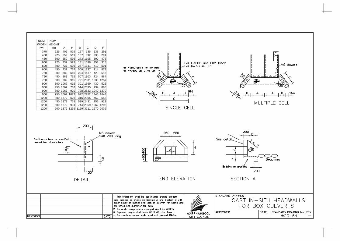
Note: Standard headwalls shall beused where the speed limit is 60km/hr or less, or where the culvert is offset more than 6metres from the edge of the traffick lane.
85° - 95°
(Refer Vicroadsstandard drawingSD 1991)
A Aug 04DRIVEABLE ENDWALL
B Aug 10MAX BATTER SLOPES 1IN3
NOM NOMWIDTH HEIGHT
(w) (h) A H B C D F375 225 402 519 167 735 238 291450 225 559 519 167 892 238 291450 300 559 595 273 1105 390 476600 225 737 529 181 1098 258 315600 300 737 605 287 1311 410 501600 450 737 757 500 1737 714 872750 300 889 610 294 1477 420 513750 450 889 762 507 1903 724 884750 600 889 915 721 2331 1030 1257900 300 1067 615 301 1669 430 525900 450 1067 767 514 2095 734 896900 600 1067 920 728 2523 1040 1270900 750 1067 1073 942 2952 1346 1643
1200 300 1372 626 316 2005 452 5521200 450 1372 778 529 2431 756 9231200 600 1372 931 744 2859 1062 12961200 900 1372 1235 1169 3711 1670 2039
id53
0949
125
pdfM
achi
ne b
y B
road
gun
Sof
twar
e -
a g
reat
PD
F w
riter
! -
a gr
eat P
DF
cre
ator
! - h
ttp://
ww
w.p
dfm
achi
ne.c
om h
ttp://
ww
w.b
road
gun.
com

APPROVED DATE STANDARD DRAWING No REVWARRNAMBOOLCITY COUNCILREVISION DATE
STANDARD DRAWING
A
NOTES
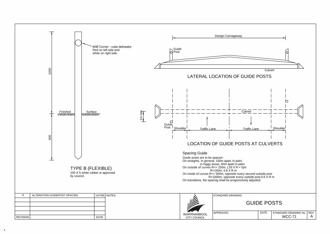
GUIDE POSTS
WCC-71
100 X 5 white rubber or approvedby council.
TYPE B (FLEXIBLE)
Finished Surface
80Ø Corner - cube delineatorRed on left side andwhite on right side.60
010
50
Design Carriageway
LATERAL LOCATION OF GUIDE POSTS
GuidePost
Culvert
Culvert
GuidePost Shoulder Traffic Lane
LOCATION OF GUIDE POSTS AT CULVERTS
Guide posts are to be spaced:-On straights, in general, 150m apart, in pairs
Spacing Guide
in foggy areas, 60m apart in pairsOn outside of curves R<= 150m, (.03 X R + 5)m
R>150m, 0.6 X R m
1m m
in
Traffic Lane Shoulder
On inside of curves R<= 500m, opposite every second outside postR>1000m, opposite every outside post.0.6 X R m
On transitions, the spacing shall be progressively adjusted.
A ALTERATION GUIDEPOST SPACING 14/7/05
id52
4296
484
pdfM
achi
ne b
y B
road
gun
Sof
twar
e -
a g
reat
PD
F w
riter
! -
a gr
eat P
DF
cre
ator
! - h
ttp://
ww
w.p
dfm
achi
ne.c
om h
ttp://
ww
w.b
road
gun.
com

$ BACK STAY DETAILS
$ BACK STAY DETAILS
id18
9453
90 p
dfM
achi
ne b
y B
road
gun
Sof
twar
e -
a g
reat
PD
F w
riter
! -
a gr
eat P
DF
cre
ator
! - h
ttp://
ww
w.p
dfm
achi
ne.c
om h
ttp://
ww
w.b
road
gun.
com


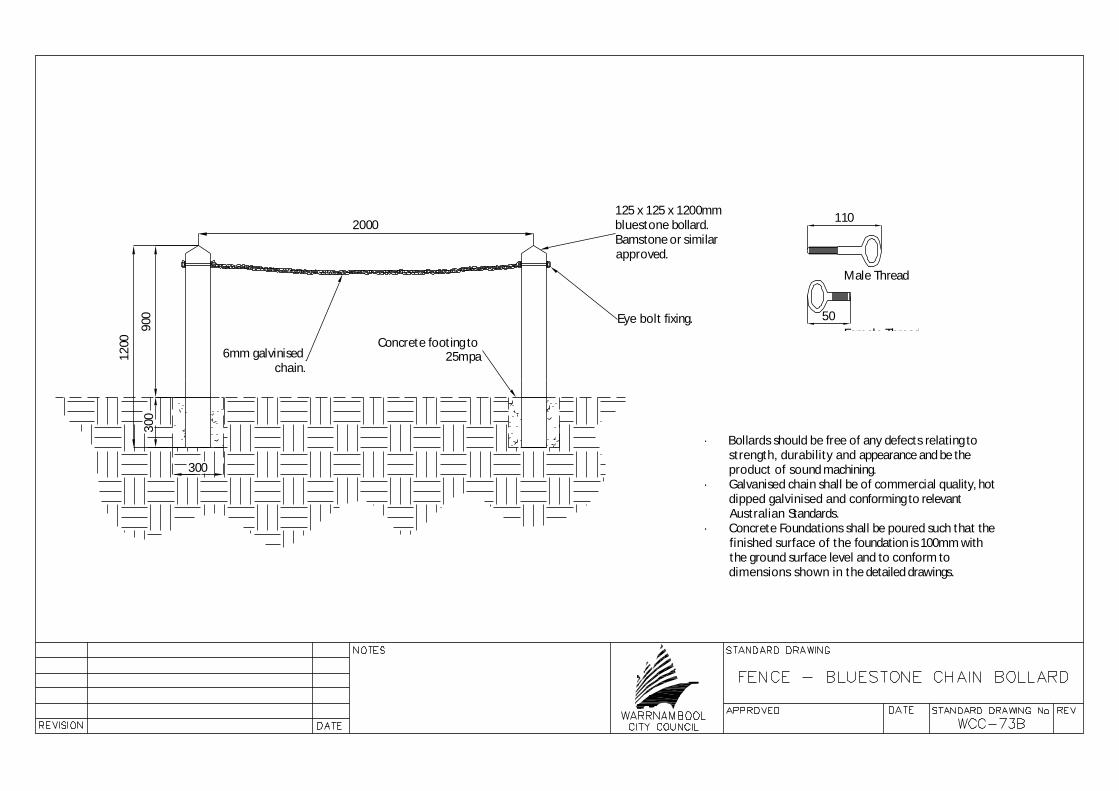
6mm galvinisedchain.
Eye bolt fixing.
Concrete footing to25mpa
900
300
1200
300
2000125 x 125 x 1200mmbluestone bollard.Bamstone or similarapproved.
110
50Female Thread
Male Thread
· Bollards should be free of any defects relating tostrength, durability and appearance and be theproduct of sound machining.
· Galvanised chain shall be of commercial quality, hotdipped galvinised and conforming to relevantAustralian Standards.
· Concrete Foundations shall be poured such that thefinished surface of the foundation is 100mm withthe ground surface level and to conform todimensions shown in the detailed drawings.
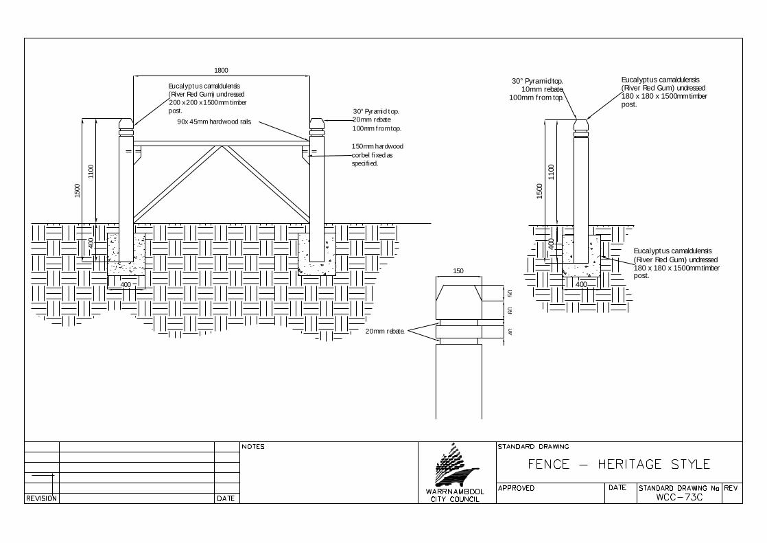
1100
400
1500
30° Pyramid top.20mm rebate100mm from top.
1800
Eucalyptus camaldulensis(River Red Gum) undressed200 x 200 x 1500mm timberpost.
90x 45mm hardwood rails.
150mm hardwoodcorbel fixed asspecified.
400
1100
400
400
1500
30° Pyramid top.10mm rebate
100mm from top.
Eucalyptus camaldulensis(River Red Gum) undressed180 x 180 x 1500mm timberpost.
Eucalyptus camaldulensis(River Red Gum) undressed180 x 180 x 1500mm timberpost.
5060
40
150
20mm rebate.

id52
4479
265
pdfM
achi
ne b
y B
road
gun
Sof
twar
e -
a g
reat
PD
F w
riter
! -
a gr
eat P
DF
cre
ator
! - h
ttp://
ww
w.p
dfm
achi
ne.c
om h
ttp://
ww
w.b
road
gun.
com

id52
4524
265
pdfM
achi
ne b
y B
road
gun
Sof
twar
e -
a g
reat
PD
F w
riter
! -
a gr
eat P
DF
cre
ator
! - h
ttp://
ww
w.p
dfm
achi
ne.c
om h
ttp://
ww
w.b
road
gun.
com
THE LOCATION OF UNDERGROUND SERVICES AREAPPROXIMATE ONLY, AND THEIR EXACT POSITIONSHOULD BE PROVEN ON SITE. NO GUARANTEE IS
GIVEN THAT ALL EXISTING SERVICES ARE SHOWN.
WARNINGBEWARE OF UNDERGROUND SERVICES
APPROVED DATE STANDARD DRAWING No REVWARRNAMBOOLCITY COUNCILREVISION DATE
STANDARD DRAWINGNOTES
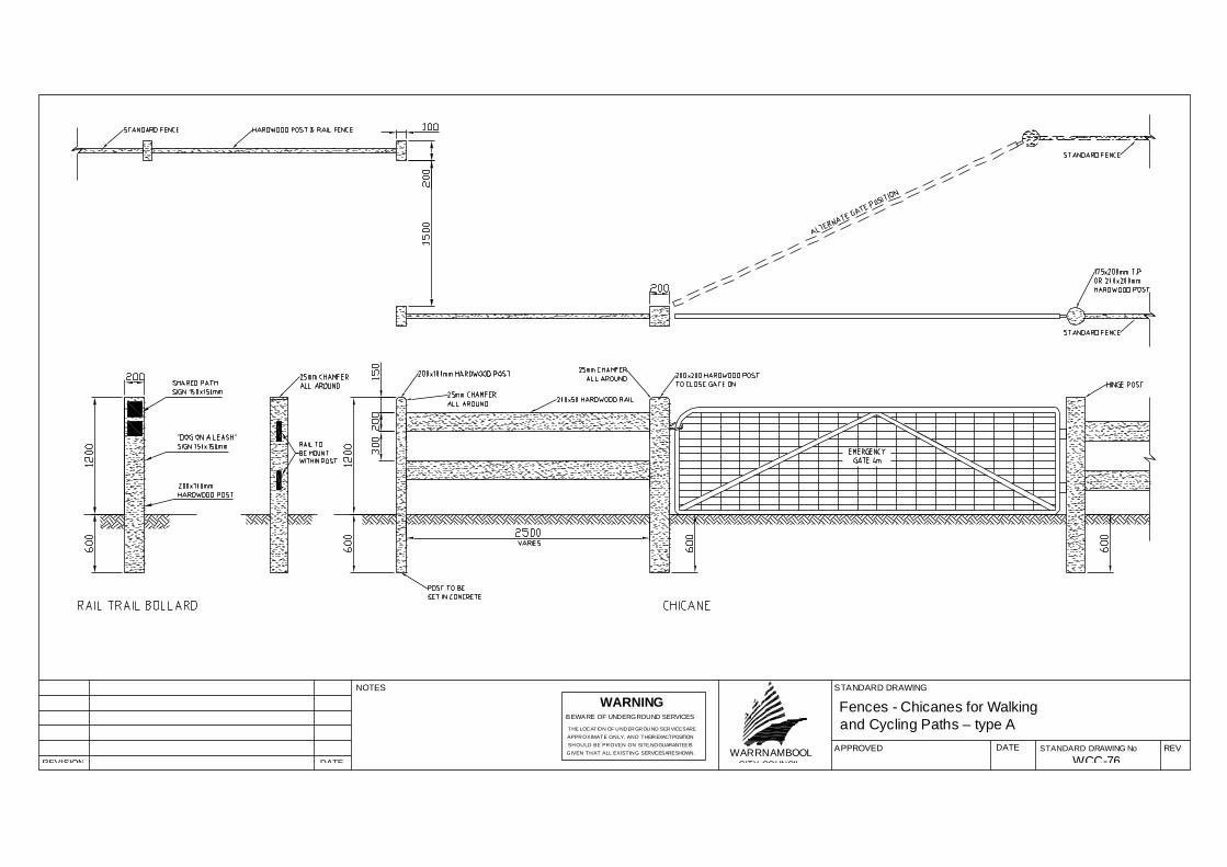
WCC-76
Fences - Chicanes for Walkingand Cycling Paths – type A

EXACT POSITION SHOULD BE PROVEN ON SITE.
WARNINGBEWARE OF UNDERGROUND SERVICES
RETAINING WALL
APPROVED DATE STANDARD DRAWING No REVWARRNAMBOOLCITY COUNCILREVISION DATE
STANDARD DRAWINGNOTES
WCC-77
···


APPROVED DATE STANDARD DRAWING No REVWARRNAMBOOLCITY COUNCILREVISION DATE
STANDARD DRAWING
-
PLANTING IN MEDIANS
WCC-82
RootBall
50
5% 5%
100 nom approved mulch
600 deep nylex root barrieror approved alternative.
Garden soil, light compaction only.
Backfill, original subgrade materiallight compaction only.
150 min loosened material
300
min
100
nom
backfillTopsoil
Backfill
Nylex root barrier
150
nom
ROOT BARRIER
Scoria filter
PLANTING IN MEDIANS
NotesPlantingProvide hole 3 to 4 times the size of plant container.The bottom of the hole shall be loosened to a depth of 150mm.Backfill with approved garden soil to 70mm below root ball level.
Prior to planting, place 5 litres of water into hole and allow to soak away.
Add approved garden soil and place indisturbed root ball into hole so thatcrown of tree is at correct level, backfill to half root ball height.
Add Agriform slow release 10 gram tablets of NPK 20:4:3:4:1 analysis to each tree.Provide 2 tablets for trees up to 500mm high, 3 tablets for trees over 500mm high.Place tablets equidistant around around plant.
Complete backfilling with approved garden soil to avoid air pockets.
Form a saucer shaped depression around base of tree and water immediately.
Weed control mat. Double outer edges and pin with 4min galvanised pegs.
Root BarriersTrench width 75mm min, 1200mm nom depth, or to solid material when approved by
Provide scoria filter and connect to an outlet pipe when directed by the superintendent.
Insert nylex root barrier and backfill using a blend of spoil from the trench and sodium
The ratio of bentonite to soil may vary depending on the type of soil:-ie 1 : 10 for clay, 1 : 1 for light sandy material.
Trench shall not be located closer than half the distance from canopy drip line and
Planting in MediansSubsoil drain to be diverted around root barrier.
uPVC unslotted pipe to be load for 3m upstream and downstream of trees.
the superintendent.
bentonite.
trunk of tree.
id52
4785
187
pdfM
achi
ne b
y B
road
gun
Sof
twar
e -
a g
reat
PD
F w
riter
! -
a gr
eat P
DF
cre
ator
! - h
ttp://
ww
w.p
dfm
achi
ne.c
om h
ttp://
ww
w.b
road
gun.
com

APPROVED DATE STANDARD DRAWING No REVWARRNAMBOOLCITY COUNCILREVISION DATE
STANDARD DRAWING
-
NOTES
WCC-91
BO
UN
DA
RY
LIN
E
BUILDING LINE
OFC
id52
4850
468
pdfM
achi
ne b
y B
road
gun
Sof
twar
e -
a g
reat
PD
F w
riter
! -
a gr
eat P
DF
cre
ator
! - h
ttp://
ww
w.p
dfm
achi
ne.c
om h
ttp://
ww
w.b
road
gun.
com

id52
4891
375
pdfM
achi
ne b
y B
road
gun
Sof
twar
e -
a g
reat
PD
F w
riter
! -
a gr
eat P
DF
cre
ator
! - h
ttp://
ww
w.p
dfm
achi
ne.c
om h
ttp://
ww
w.b
road
gun.
com
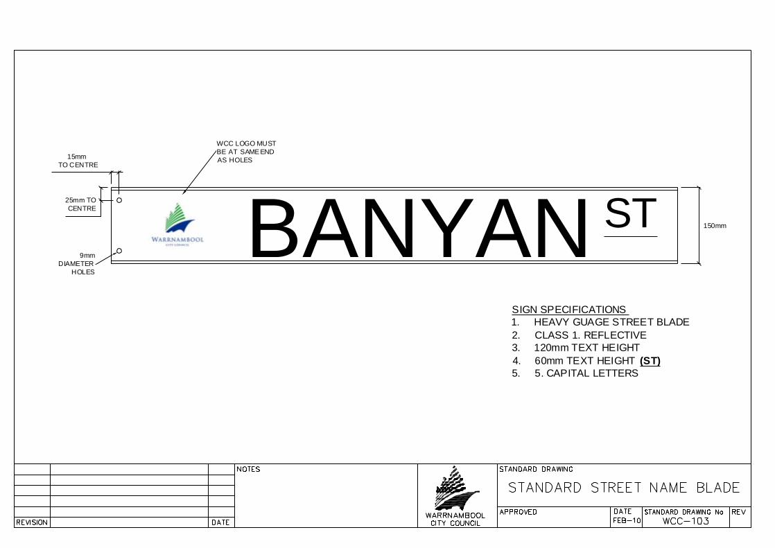
BANYAN ST15mm
TO CENTRE
25mm TO CENTRE
150mm
WCC LOGO MUSTBE AT SAME ENDAS HOLES
9mmDIAMETER
HOLES
SIGN SPECIFICATIONS1. HEAVY GUAGE STREET BLADE2. CLASS 1. REFLECTIVE3. 120mm TEXT HEIGHT4. 60mm TEXT HEIGHT (ST)5. 5. CAPITAL LETTERS