Wallops Arc Second Pointer - NASA · Wallops Arc Second Pointer WASP Description Subsystems ... •...
14
Goddard Space Flight Center 1 Wallops Arc Second Pointer WASP Description Subsystems X-Calibur Flight 2017 Test Flight Current Collaborations Wallops Flight Facility David Stuchlik – Code 820 NASA/GSFC/Wallops May 2017 https://ntrs.nasa.gov/search.jsp?R=20170004639 2018-11-11T20:13:57+00:00Z
Transcript of Wallops Arc Second Pointer - NASA · Wallops Arc Second Pointer WASP Description Subsystems ... •...
Goddard Space
Flight Center
1
Wallops Flight Facility
Wallops Arc Second Pointer
WASP Description
Subsystems
X-Calibur Flight
2017 Test Flight
Current Collaborations
Wallops Flight Facility
David Stuchlik – Code 820
NASA/GSFC/Wallops
May 2017
https://ntrs.nasa.gov/search.jsp?R=20170004639 2018-11-11T20:13:57+00:00Z

Goddard Space
Flight Center
2
Wallops Flight Facility
WASP
WASP is a NASA developed Fine
Pointing System adaptable to a
variety of Science Instruments.
Standardized System with
Reusable Parts to Minimize the
Cost to Users and NASA.
Supports Multiple Science
Disciplines and a wide range of
Masses and Inertias.
Currently Operational and
Available for Science
Collaborations
Wallops Flight FacilityWallops Flight Facility

Goddard Space
Flight Center
3
Wallops Flight Facility
616 NT
WASP Functional Overview
591 NT54 Days
Rotator provides coarse azimuth pointing of
gondola (to within ~+3°)
Fine instrument pointing achieved using
gondola mounted pitch/yaw gimbal
Two opposing gimbal hubs per axis enable
sub-arcsecond stability with a design that
eliminates static friction
Control torque for each axis provided by
large diameter brushless DC torque motor
Instrument inertial attitude integrated from
LN251 Fiber Optic Gyro
Extended Kalman Filter (EKF) used to
merge unit vectors from Star Tracker and
other sources (e.g. sun sensor or science
target) into integrated solution
Control torques computed from modified
Proportional-Integral-Derivative (PID)
compensator in each axis

Goddard Space
Flight Center
4
Wallops Flight Facility
Inner Frame
Hub
Outer Frame
Telescope
Pitch Axis
Telescope
Yaw Axis
Inner Frame
Hub
Outer Frame
Telescope
Pitch Axis
Telescope
Yaw Axis
• Gimbal Frames hold Hubs, Maintain alignment
critical to minimize required torque.
• Outer Frame can be used as Gondola Structure.
• Recent Developments– Larger Inner Frame Provides full 1 meter clearance
with existing Outer Frame
– XL Design provides ~1.2 meter clearance and has
embedded hubs to eliminate counterweights
WASP Standard Parts
X-Calibur Larger Inner Frame GHAPS XL Inner Frame
Goddard Space
Flight Center
5
Wallops Flight Facility
WASP Motor Hubs and Resolver Hubs
• Each Axis uses One Motor Hub & One Resolver
Hub.
• Constantly Rotating central shaft eliminates
static friction (Stiction) when direction is
reversed.
• Shaft Rotated with Electric Motor through
Reduction Gear.
• Motor Hub has large diameter Torque Motor
which provides the control torque.
• Resolver Hub has resolver which provides Angle
Measurement between two halves of the Hub.
• Hubs support full mass of Pointed Structure and
10 G loading.
WASP Hubs

Goddard Space
Flight Center
6
Wallops Flight Facility
Avionics Deck
• ~21” x ~17” aluminum deck
• Main Flight Computer, CARDS Flight Computer,
Enclosures for Resolver Interface, Power
Relays, Motor Driver Interface, GPS Receiver,
H-Bridge Circuits, and Housekeeping.
3 Axis Fiber Optic Gyro
• Northop Grumman (NG) LN-251 Inertial
Navigation System
• Used by WASP as Inertial Rate Unit (IRU).
• NG installed new firmware in 2016 reducing
noise and improving pointing performance.
WASP Avionics Deck & Gyro

Goddard Space
Flight Center
7
Wallops Flight Facility
Dynamic Balance Trim Weights
• Three Dynamic Balance Trim Weights flown,
one in each Axis.
• Commanded from Ground if needed.
• Brass Weight driven by small DC motor.
Caging Mechanism
• Linear Actuator and electric motor driven cam
provide redundant methods for releasing and
recaging.
• Uncage - Linear Actuator shaft retracts or motor
cam pushes latch hook.
• Cage – Shaft extended, hook spring loaded or
drive into place, then extend shaft.
WASP Trim Weights & Latch

Goddard Space
Flight Center
8
Wallops Flight Facility
• CARDS – Celestial Attitude Reference and
Determination System– COTS camera and processor, custom light baffle
– Low-cost system for providing attitude inputs into WASP
Control System
• Operational specifications• Point Grey Camera, 100 mm Stingray Lens, RTD flight
processor
• Field of View: 5.9 x 4.4 degrees
• Tracking solutions: 10 Hz
• Supplies target matched unit vectors or quaternions, depending
on the application, over Async Serial or Ethernet interface
WASP Daytime Star Tracker
Goddard Space
Flight Center
9
Wallops Flight Facility
616 NT
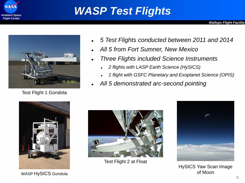
WASP Test Flights
591 NT54 Days
5 Test Flights conducted between 2011 and 2014
All 5 from Fort Sumner, New Mexico
Three Flights included Science Instruments
2 flights with LASP Earth Science (HySICS)
1 flight with GSFC Planetary and Exoplanet Science (OPIS)
All 5 demonstrated arc-second pointing
HySICS Yaw Scan Image
of Moon
Test Flight 1 Gondola
WASP HySICS Gondola
Test Flight 2 at Float

Goddard Space
Flight Center
10
Wallops Flight Facility
X-Calibur Science Flight
First Science Mission with WASP
PI Henric Krawczynski, Washington University in St. Louis (WUSTL) Measure Linear polarization of hard X-rays in the energy range of 25-70 keV.
255 shell X-ray focusing mirror and a rotating Polarimeter.
Rigid truss to maintain alignment between mirror and the detector 8 meters away
Pointing Requirements
Compute attitude with knowledge uncertainty within 30-asec (3-sigma)
Hold X-ray mirror boresight to target within 30-asec (3-sigma)
September 17, 2016, flight duration 24 hours and 37 minutes
Fort Sumner, NM. Longest flight of WASP to date
X-Calibur Design
with Antarctic Flight
Solar Panels
Goddard Space
Flight Center
11
Wallops Flight Facility
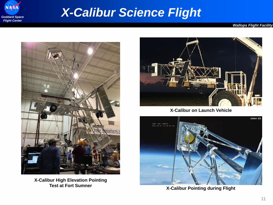
X-Calibur Science Flight
X-Calibur Pointing during Flight
X-Calibur on Launch Vehicle
X-Calibur High Elevation Pointing
Test at Fort Sumner

Goddard Space
Flight Center
12
Wallops Flight Facility
X-Calibur Pointing Performance
• Tracking errors consistent with preflight
simulation and ground testing – sub-arc
second.
• Star Tracker Residual provide indication of
attitude estimation errors that contributes to
absolute pointing error
• Roll coupling into pitch/yaw axes indicative of
misalignment between Star Tracker and
Inertial Rate Unit
• Able to identify misalignment by batch
processing 5-10 min segments of flight data
• Post Flight Improvements
• Misalignment correction technique
ground tested that eliminates roll
coupling.
• New centriod algorithm ground tested
that improves daytime performance with
high ambient background levels.
• Both to be tested on 2017 WASP Test
Flight.

Goddard Space
Flight Center
13
Wallops Flight Facility
WASP 2017 Test Flight
• Combined with CSBF LDB Test Systems
• Includes refurbished parts of X-Calibur,
OPIS, and Test Flight Two
• Evaluate daytime Star Tracker performance
improvements.
• Evaluate flight prototype GHAPS Baffle for
star tracker.
• Evaluate GHAPS configuration of modified
WASP Avionics mounting locations.
• Sept. 2017 Fort Sumner
Trim Weights
GHAPS Baffle
and Star Tracker
LN251WASP Avionics in
GHAPS OTA
Configuration 10” square steel
tube used on TF1
and TF2

Goddard Space
Flight Center
14
Wallops Flight Facility
Current WASP Mission Support
GHAPSGondola for High Altitude Planetary Science
• NASA – GRC, MSFC, GSFC, WFF
• Developing a Reusable Gondola
Platform for Planetary Science
Instruments
• One Meter optical telescope, UV, IR,
visible
• Initial flight planned for 2020.
PICTURE-CPlanetary Imaging Concept Testbed Using a
Recoverable Experiment – Coronagraph• PI Supriya Chakrabarti U Mass Lowell
(UML)
• 60 cm Telescope with Coronagraph to
Image Debris Disks of Nearby Systems
• Flights planned for 2018 and 2019.