Wall-mounted condensing boilers - BAXIservice - BAXI … HT_GB.pdf · · 2017-02-23BAXI S.p.A.,...
36
Wall-mounted condensing boilers Installer’s and User’s Instructions UNI EN ISO 9001 CERTIFICAZIONE DEI SISTEMI QUALITA' DELLE AZIENDE HT BAXI S.p.A., one of the leading European enterprises to produce central heating and hot water devices for domestic use (wall-mounted gas-operated boilers, floor-standing boilers and electrical water-heaters) has obtained the CSQ certificate of conformity to the UNI EN ISO 9001 norms. This certificate guarantees that the Quality System applied at the BAXI S.p.A. factory in Bassano del Grappa, where your boiler was produced, meets the standards of the UNI EN ISO 9001 norm, which is the strictest and concerns all organization stages and operating personnel involved in the production and distribution processes. 0085
Transcript of Wall-mounted condensing boilers - BAXIservice - BAXI … HT_GB.pdf · · 2017-02-23BAXI S.p.A.,...

Wall-mounted condensing boilers
Installer’s and User’s Instructions
UNI EN ISO 9001
CERTIFICAZIONE DEI SISTEMIQUALITA' DELLE AZIENDE
HT
BAXI S.p.A., one of the leading European enterprises to produce central heating and hot water devices for domestic use (wall-mounted gas-operated boilers, floor-standing boilers and electrical water-heaters) has obtained the CSQ certificate of conformity to the UNI EN ISO 9001 norms. This certificate guarantees that the Quality System applied at the BAXI S.p.A. factory in Bassano del Grappa, where your boiler was produced, meets the standards of the UNI EN ISO 9001 norm, which is the strictest and concerns all organization stages and operating personnel involved in the production and distribution processes.
0085
Dear Customer,
We are sure your new boiler will comply with all your requirements.
Purchasing one of the BAXI products satisfies your expectations: good functioning, simplicity and ease of use.
Do not dispose of this booklet without reading it: you can find here some very useful information, which will help you to run your boiler correctly and efficiently.
Do not leave any parts of the packaging (plastic bags, polystyrene, etc.) within childrenʼs reach as they are a potential source of danger.
BAXI boilers bear the CE mark in compliance with the basic requirements as laid down in the following Directives:- Gas Directive 90/396/CEE- Performance Directive 92/42/CEE- Electromagnetic Compatibility Directive 89/336/CEE- Low Voltage Directive 73/23/CEE
Contents
1. Instructions prior to installation 42. Instructions prior to commissioning 43. Commissioning of the boiler 54. Filling the boiler 105. Turning off the boiler 106. Prolonged standstill of the system. Frost protection 117. Gas change 118. Servicing instructions 11
Instructions pertaining to the user
9. General information 1210. Instructions prior to installation 1211. Boiler installation 1312. Boiler size 1313. Fittings present in the packaging 1414. Installation of flue and air ducts 1415. Connecting the mains supply 1816. Gas change modalities 2417. Setting the boiler parameters 2718. Control and operation devices 2819. Positioning of the ignition and flame sensing electrode 2920. Check of combustion parameters 2921. Activating the flue-sweeper function 2922. Output / pump head performances 3023. How to disassemble the DHW heat exchanger 3024. Cleaning the cold water filter 3125. Annual service 3126. Boiler schematic 32-3327. Illustrated wiring diagram 34-3528. Technical data 36
Instructions pertaining to the installer

4
Instructions pertaining to the user
2. Instructions prior to commissioning
Initial lighting of the boiler must be carried out by a licensed technician. Ensure the following ope-rations are carried out:a) compliance of boiler parameters with (electricity, water, gas) supply systems settings.b) compliance of installation with the laws and regulations in force.c) appropriate connection to the power supply and grounding of the appliance.The names of authorized Service Centres are listed on the accompanying sheet. Failure to observe the above will render the guarantee null and void.Prior to commissioning remove the protective plastic coating from the unit. Do not use any tools or abrasive detergents as you may spoil the painted surfaces.
This boiler is designed to heat water at a lower than boiling temperature at atmospheric pressure. The boiler must be connected to a central heating system and to a domestic hot water supply system in compliance with its performances and output power.Have the boiler installed by a Qualified Service Engineer and ensure the following operations are accomplished:
a) careful checking that the boiler is fit for operation with the type of gas available. For more details see the notice on the packaging and the label on the appliance itself.
b) careful checking that the flue terminal draft is appropriate; that the terminal is not obstructed and that no other appliance exhaust gases are expelled through the same flue duct, unless the flue is especially designed to collect the exhaust gas coming from more than one appliance, in conformity with the laws and regulations in force.
c) careful checking that, in case the flue has been connected to pre-existing flue ducts, thorough cleaning has been carried out in that residual combustion products may come off during operation of the boiler and obstruct the flue duct.
d) to ensure correct operation of the appliance and avoid invalidating the guarantee, observe the following precautions:
1. Hot water circuit:1.1. If the water hardness is greater than 20 °F (1 °F = 10 mg calcium carbonate per litre of water)
a polyphosphate or comparable treatment system responding to current regulations.1.2. Domestic Hot Water circuit must be thoroughly flushed after the installation of the appliance
and before its use.
2. Heating circuit2.1. new system Before proceeding with installation of the boiler, the system must be cleaned and flushed
out thoroughly to eliminate residual thread-cutting swarf, solder and solvents if any, using suitable proprietary products.
To avoid damaging metal, plastic and rubber parts, use only neutral cleaners, i.e. non-acid and non alkaline. The recommended products for cleaning are:
SENTINEL X300 or X400 and FERNOX heating circuit restore. To use this product proceeding strictly in accordance with the makerʼs directions.
2.2. existing system Before proceeding with installation of the boiler, the system must be cleaned and flushed
out to remove sludge and contaminants, using suitable proprietary products as described in section 2.1.
To avoid damaging metal, plastic and rubber parts, use only neutral cleaners, i.e. non-acid and non-alkaline such as SENTINEL X100 and FERNOX heating circuit protective. To use this product proceeding strictly in accordance with the makerʼs directions.
Remember that the presence of foreign matter in the heating system can adversely affect the operation of the boiler (e.g. overheating and noisy operation of the heat exchanger).
Failure to observe the above will render the guarantee null and void.
1. Instructions prior to installation

5
3-1. Description of keys
(2) This key can be pressed to set the central heating water output temperature as described in point 3-3.
(3) This key can be pressed to set the domestic hot water temperature as described in point 3-4.
(10) Central heating mode operating key The key can be pressed to activate four boiler central heating operating modes; these
modes are identified by a black cursor line underneath the relative symbol on the display, and are as follows:
KEYS DISPLAY SYMBOLS
Central heating mode setting key
Data display reset key
Parameter setting key (increase value)
Parameter setting key (decrease value)
Program access and scroll key
Program access and scroll keys
Reset key
Domestic hot water temperature setting key
Central heating water temperature setting key
Domestic hot water on/off key
Resettable alarm warning
Flame present (on)
Outdoor temperature
Standby (off)
Operation in manual mode at minimum temperature
Operation in manual mode at the maxi-mum temperature set
Operation in automatic mode
Operation in central heating mode
Operation in domestic hot water mode
0205
03_1
100
Figure 1
SECONDARY display
MAIN display
To correctly light the burner proceed as follows:1) provide power supply to the boiler;2) open the gas cock;3) follow the directions given below regarding the adjustments to be made at the boiler control panel.
3. Commissioning of the boiler
6
0205
03_0
800
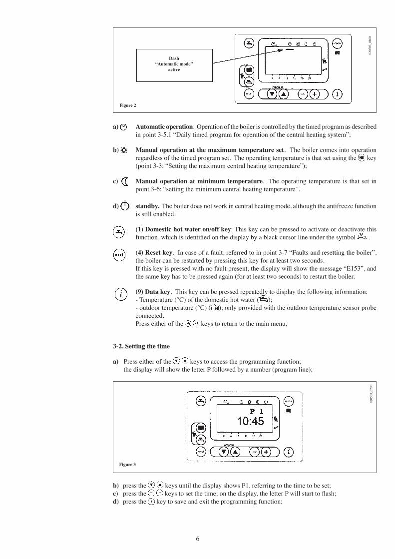
Figure 2
a) Automatic operation. Operation of the boiler is controlled by the timed program as described in point 3-5.1 “Daily timed program for operation of the central heating system”;
b) Manual operation at the maximum temperature set. The boiler comes into operation regardless of the timed program set. The operating temperature is that set using the key (point 3-3: “Setting the maximum central heating temperature”);
c) Manual operation at minimum temperature. The operating temperature is that set in point 3-6: “setting the minimum central heating temperature”.
d) standby. The boiler does not work in central heating mode, although the antifreeze function is still enabled.
(1) Domestic hot water on/off key: This key can be pressed to activate or deactivate this function, which is identified on the display by a black cursor line under the symbol .
(4) Reset key. In case of a fault, referred to in point 3-7 “Faults and resetting the boiler”, the boiler can be restarted by pressing this key for at least two seconds.
If this key is pressed with no fault present, the display will show the message “E153”, and the same key has to be pressed again (for at least two seconds) to restart the boiler.
(9) Data key. This key can be pressed repeatedly to display the following information: - Temperature (°C) of the domestic hot water ( ); - outdoor temperature (°C) ( ); only provided with the outdoor temperature sensor probe
connected. Press either of the keys to return to the main menu.
3-2. Setting the time
a) Press either of the keys to access the programming function; the display will show the letter P followed by a number (program line);
0205
03_0
700
Figure 3
Dash“Automatic mode”
active
b) press the keys until the display shows P1, referring to the time to be set;c) press the keys to set the time; on the display, the letter P will start to flash;d) press the key to save and exit the programming function;
7
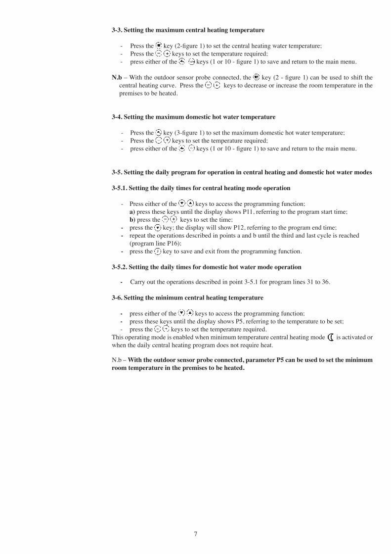
3-3. Setting the maximum central heating temperature - Press the key (2-figure 1) to set the central heating water temperature; - Press the keys to set the temperature required; - press either of the keys (1 or 10 - figure 1) to save and return to the main menu.
N.b – With the outdoor sensor probe connected, the key (2 - figure 1) can be used to shift the central heating curve. Press the keys to decrease or increase the room temperature in the premises to be heated.
3-4. Setting the maximum domestic hot water temperature - Press the key (3-figure 1) to set the maximum domestic hot water temperature; - Press the keys to set the temperature required; - press either of the keys (1 or 10 - figure 1) to save and return to the main menu.
3-5. Setting the daily program for operation in central heating and domestic hot water modes
3-5.1. Setting the daily times for central heating mode operation
- Press either of the keys to access the programming function; a) press these keys until the display shows P11, referring to the program start time; b) press the keys to set the time; - press the key; the display will show P12, referring to the program end time; - repeat the operations described in points a and b until the third and last cycle is reached (program line P16); - press the key to save and exit from the programming function.
3-5.2. Setting the daily times for domestic hot water mode operation
- Carry out the operations described in point 3-5.1 for program lines 31 to 36.
3-6. Setting the minimum central heating temperature
- press either of the keys to access the programming function; - press these keys until the display shows P5, referring to the temperature to be set; - press the keys to set the temperature required.This operating mode is enabled when minimum temperature central heating mode is activated or when the daily central heating program does not require heat.
N.b – With the outdoor sensor probe connected, parameter P5 can be used to set the minimum room temperature in the premises to be heated.

8
3-8. Fault warnings and resetting the boiler
If a fault occurs, a flashing warning code appears on the display.The fault warnings appear on the main display (figure 1 a) together with the symbol (Figure 4).To reset, press the reset button for at least two seconds.
3-7. Table of user-settable parameters
0205
03_0
500
Figure 4
Note: Parameters from P31 to P36 can be displayed only if the domestic hot water program has been enabled as described in chapter 17 for the attention of the installer (parameter H91).
Range
0…23:59
25..80
00:00…24:00
00:00…24:00
00:00…24:00
00:00…24:00
00:00…24:00
00:00…24:00
00:00…24:00
00:00…24:00
00:00…24:00
00:00…24:00
00:00…24:00
00:00…24:00
0...1
Factorysetting
———-
25
6:00
22:00
0:00
0:00
0:00
0:00
0:00
24:00
0:00
0:00
0:00
0:00
0
Parameter description
Time of day setting
Minimum central heating temperature setting (°C)
Start of first daily period of automatic central heating
End of first daily period of automatic central heating
Start of second daily period of automatic central heating
End of second daily period of automatic central heating
Start of third daily period of automatic heating
End of third daily period of automatic central heating
Start of first daily period of domestic hot water production
End of first daily period of domestic hot water production
Start of second daily period of domestic hot water production
End of second daily period of domestic hot water production
Start of third daily period of domestic hot water production
Fine End of third daily period of domestic hot water production
Reset of daily central heating and domestic hot water production programs (factory settings). Press the - + keys together for about 3 seconds; the number 1 appears on the display. Confirm by pressing either of the keys
ParameterN.
P1
P5
P11
P12
P13
P14
P15
P16
P31
P32
P33
P34
P35
P36
P45
9
0510
_270
1
Figure 4.1
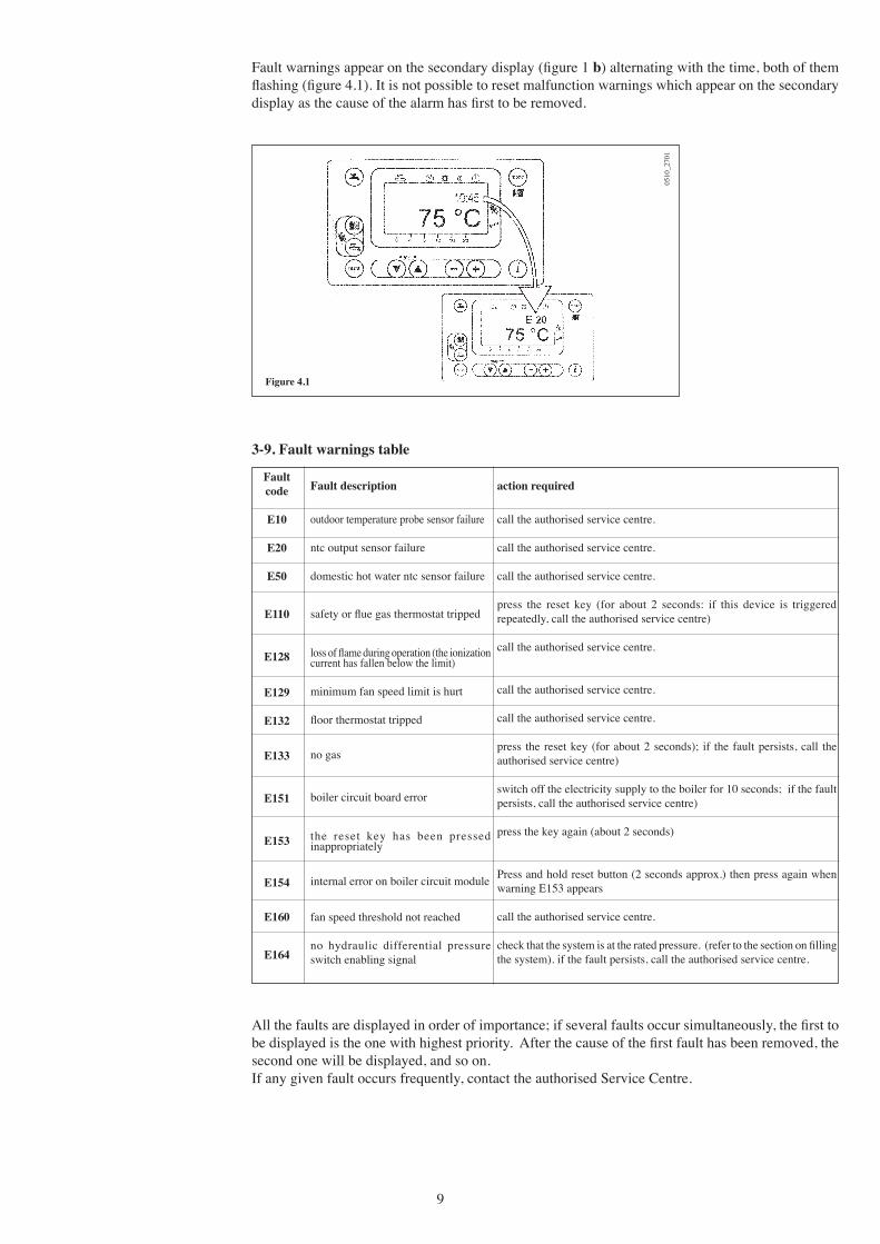
Fault warnings appear on the secondary display (figure 1 b) alternating with the time, both of them flashing (figure 4.1). It is not possible to reset malfunction warnings which appear on the secondary display as the cause of the alarm has first to be removed.
All the faults are displayed in order of importance; if several faults occur simultaneously, the first to be displayed is the one with highest priority. After the cause of the first fault has been removed, the second one will be displayed, and so on.If any given fault occurs frequently, contact the authorised Service Centre.
action required
call the authorised service centre.
call the authorised service centre.
call the authorised service centre.
press the reset key (for about 2 seconds: if this device is triggered repeatedly, call the authorised service centre)
call the authorised service centre.
call the authorised service centre.
call the authorised service centre.
press the reset key (for about 2 seconds); if the fault persists, call the authorised service centre)
switch off the electricity supply to the boiler for 10 seconds; if the fault persists, call the authorised service centre)
press the key again (about 2 seconds)
Press and hold reset button (2 seconds approx.) then press again when warning E153 appears
call the authorised service centre.
check that the system is at the rated pressure. (refer to the section on filling the system). if the fault persists, call the authorised service centre.
Fault description
outdoor temperature probe sensor failure
ntc output sensor failure
domestic hot water ntc sensor failure
safety or flue gas thermostat tripped
loss of flame during operation (the ionization current has fallen below the limit)
minimum fan speed limit is hurt
floor thermostat tripped
no gas
boiler circuit board error
the reset key has been pressed inappropriately
internal error on boiler circuit module
fan speed threshold not reached
no hydraulic differential pressure switch enabling signal
3-9. Fault warnings table
Faultcode
E10
E20
E50
E110
E128
E129
E132
E133
E151
E153
E154
E160
E164
10
To shut down the boiler switch off the electrical supply to the appliance.5. Turning off the boiler
The boiler is equipped with a hydraulic differential pressure switch that will inhibit the operation of the boiler in the event of the pump seizing or running dry.
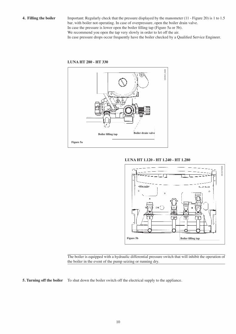
Important: Regularly check that the pressure displayed by the manometer (11 - Figure 20) is 1 to 1.5 bar, with boiler not operating. In case of overpressure, open the boiler drain valve.In case the pressure is lower open the boiler filling tap (Figure 5a or 5b).We recommend you open the tap very slowly in order to let off the air.In case pressure drops occur frequently have the boiler checked by a Qualified Service Engineer.
4. Filling the boiler
0205
03_0
400
Boiler filling tap Boiler drain valve
Figure 5a
LUNA HT 280 - HT 330
0010
2705
00
Figure 5b
LUNA HT 1.120 - HT 1.240 - HT 1.280
Boiler filling tap

11
6. Prolonged standstill of the system.
Frost protection
We recommend you avoid draining the whole system as water replacements engender purposeless and harmful limestone deposits inside the boiler and on the heating elements.In case the boiler is not operated during wintertime and is therefore exposed to danger of frost we suggest you add some specific-purpose anti-freeze to the water contained in the system (e.g.: propy-lene glycole coupled with corrosion and scaling inhibitors).The electronic management of boilers includes a ʻfrost protection ̓function in the central heating system which operates the burner to reach a heating flow temperature of 30° C when the system heating flow temperature drops below 5°C.
The frost protection function is enabled if:
* electrical supply to the boiler is on;* the gas service cock is open;* the system pressure is as required;* the boiler is not blocked.
These boilers produced for natural gas can be converted to work with LPG. Any gas change must be effected by a Qualified Service Engineer.
7. Gas change
To maintain efficient and safe operation of your boiler have it checked by a Qualified Service Engineer at the end of every operating period.Careful servicing will ensure economical operation of the system.Do not clean the outer casing of the appliance with abrasive, aggressive and/or easily flammable cleaners (i.e.: gasoline, alcohol, and so on). Always isolate the electrical supply to the appliance before cleaning it (see section 5 “Turning off the boiler”).
8. Servicing instructions
12
Instructions pertaining to the installer
This boiler is designed to heat water at a lower than boiling temperature at atmospheric pressure. The boiler must be connected to a central heating system and to a domestic hot water supply system in compliance with its performances and output power.Have the boiler installed by a Qualified Service Engineer and ensure the following operations are accomplished:
a) careful checking that the boiler is fit for operation with the type of gas available. For more details see the notice on the packaging and the label on the appliance itself.
b) careful checking that the flue terminal draft is appropriate; that the terminal is not obstructed and that no other appliance exhaust gases are expelled through the same flue duct, unless the flue is especially designed to collect the exhaust gas coming from more than one appliance, in conformity with the laws and regulations in force.
c) careful checking that, in case the flue has been connected to pre-existing flue ducts, thorough cleaning has been carried out in that residual combustion products may come off during operation of the boiler and obstruct the flue duct.
To ensure correct operation of the appliance and avoid invalidating the guarantee, observe the following precautions:
1. Hot water circuit:1.1. If the water hardness is greater than 20 °F (1 °F = 10 mg calcium carbonate per litre of water)
a polyphosphate or comparable treatment system responding to current regulations.1.2. Domestic Hot Water circuit must be thoroughly flushed after the installation of the appliance
and before its use.
2. Heating circuit
2.1. new system Before proceeding with installation of the boiler, the system must be cleaned and flushed
out thoroughly to eliminate residual thread-cutting swarf, solder and solvents if any, using suitable proprietary products.
To avoid damaging metal, plastic and rubber parts, use only neutral cleaners, i.e. non-acid and non alkaline. The recommended products for cleaning are:
SENTINEL X300 or X400 and FERNOX heating circuit restore. To use this product proceeding strictly in accordance with the makerʼs directions.
2.2. existing system Before proceeding with installation of the boiler, the system must be cleaned and flushed out
10. Instructions prior to installation
The following remarks and instructions are addressed to Service Engineers to help them carry out a faultless installation. Instructions regarding lighting and operation of the boiler are contained in the ʻInstructions pertaining to the user ̓section.Note that installation, maintenance and operation of the domestic gas appliances must be performed exclusively by qualified personnel in compliance with current standards.Please note the following:* This boiler can be connected to any type of double- or single feeding pipe convector plates,
radiators, thermoconvectors. Design the system sections as usual though taking into account the available output / pump head performances, as shown in section 22.
* Do not leave any packaging components (plastic bags, polystyrene, etc.) within childrenʼs reach as they are a potential source of danger.
* Initial lighting of the boiler must be effected by a Qualified Service Engineer.
Failure to observe the above will render the guarantee null and void.
9. General information

13
Figure 7
0205
03_0
300
12. Boiler size
Decide upon the boiler location, then tape the template on the wall.Connect the pipework to the gas and water inlets prearranged on the template lower bar.If you are either installing the boiler on a pre-existent system or substituting it, we suggest you also fit settling tanks on the system return pipework and under the boiler to collect the deposits and scaling which may remain and be circulated in the system after the purge.When the boiler is fixed on the template connect the flue and air ducts (fittings supplied by the ma-nufacturer) according to the instructions given in the following sections.Connect the condensate outlet to the siphon supplied with the boiler. Connect the siphon to a drain, making sure there is a continuous slope. Horizontal sections must be avoided.
11. Boiler installation
to remove sludge and contaminants, using suitable proprietary products as described in section 2.1.
To avoid damaging metal, plastic and rubber parts, use only neutral cleaners, i.e. non-acid and non-alkaline such as SENTINEL X100 and FERNOX heating circuit protective. To use this product proceeding strictly in accordance with the makerʼs directions.
Remember that the presence of foreign matter in the heating system can adversely affect the operation of the boiler (e.g. overheating and noisy operation of the heat exchanger).
Failure to observe the above will render the guarantee null and void.
0505
_200
1
Figure 699
1222
0300
BOILER WIDTH 450
BOILER CONNECTION POINTS
BOIL
ER H
EIG
HT
780
0211
_220
3
LUNA HT 1.280 - HT 1.240 - HT 1.120 LUNA HT 330 - HT 280
MR: G3/4 heating flowUS: G1/2 domestic hot water outletGAS: G3/4 gas inlet to the boilerES: G1/2 cold water inletRR: G3/4 heating returnSC: condensation drain
MR: G3/4 heating flowUS: G3/4 domestic hot water boiler outletGAS: G3/4 gas inlet to the boilerES: G1/2 cold water inletRR: G3/4 heating returnSC: condensation drain
14
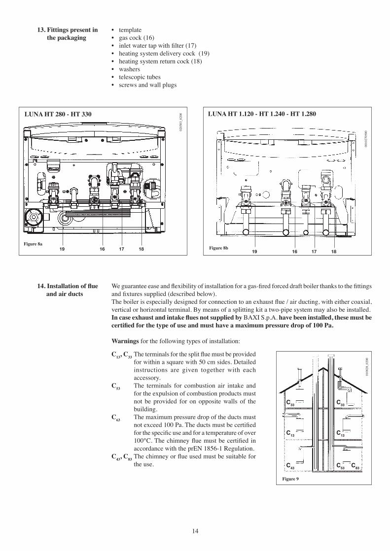
We guarantee ease and flexibility of installation for a gas-fired forced draft boiler thanks to the fittings and fixtures supplied (described below).The boiler is especially designed for connection to an exhaust flue / air ducting, with either coaxial, vertical or horizontal terminal. By means of a splitting kit a two-pipe system may also be installed.In case exhaust and intake flues not supplied by BAXI S.p.A. have been installed, these must be certified for the type of use and must have a maximum pressure drop of 100 Pa.
Warnings for the following types of installation:
14. Installation of flue and air ducts
0108
28_0
200
C33 C33
C13 C13
C43 C53 C83
Figure 9
• template• gas cock (16)• inlet water tap with filter (17)• heating system delivery cock (19)• heating system return cock (18)• washers• telescopic tubes• screws and wall plugs
13. Fittings present in the packaging
Figure 8a
0205
03_0
200LUNA HT 280 - HT 330
18171619 Figure 8b
0010
2705
00
LUNA HT 1.120 - HT 1.240 - HT 1.280
18171619
C13, C33 The terminals for the split flue must be provided for within a square with 50 cm sides. Detailed instructions are given together with each accessory.
C53 The terminals for combustion air intake and for the expulsion of combustion products must not be provided for on opposite walls of the building.
C63 The maximum pressure drop of the ducts must not exceed 100 Pa. The ducts must be certified for the specific use and for a temperature of over 100°C. The chimney flue must be certified in accordance with the prEN 1856-1 Regulation.
C43, C83 The chimney or flue used must be suitable for the use.
15
Flueterminal diameter
100 mm133 mm
-
Each 45° bendreduces the ductmax. length by
0,5 m0,25 m0,25 m
Each 90° bendreduces the ductmax. length by
1 m0,5 m0,5 m
Max. length of flue duct
10 m15 m80 m
Flue duct terminal
Coaxial Ø 60/100 mmVertical two-pipe
Horizontal two-pipe
Outerterminal diameter
100 mm80 mm80 mm
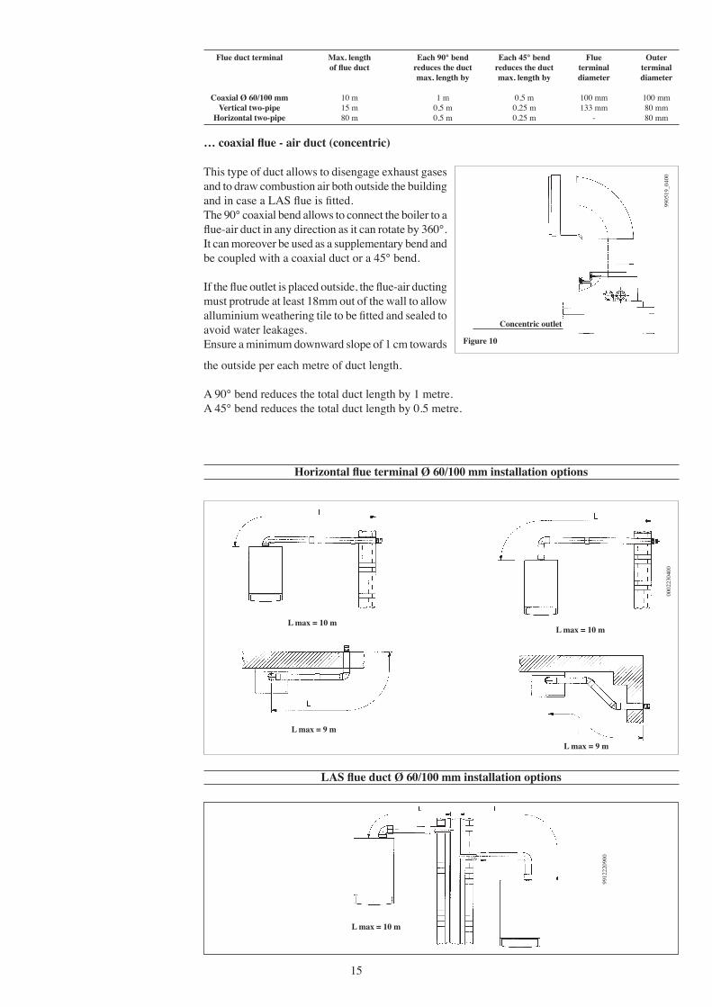
… coaxial flue - air duct (concentric)
9905
19_0
400
Concentric outlet
Figure 10
Horizontal flue terminal Ø 60/100 mm installation options
LAS flue duct Ø 60/100 mm installation options
L max = 10 m
9912
2209
00
L max = 10 m L max = 10 m
L max = 9 m
L max = 9 m
0002
2304
00
This type of duct allows to disengage exhaust gases and to draw combustion air both outside the building and in case a LAS flue is fitted.The 90° coaxial bend allows to connect the boiler to a flue-air duct in any direction as it can rotate by 360°. It can moreover be used as a supplementary bend and be coupled with a coaxial duct or a 45° bend.
If the flue outlet is placed outside, the flue-air ducting must protrude at least 18mm out of the wall to allow alluminium weathering tile to be fitted and sealed to avoid water leakages.Ensure a minimum downward slope of 1 cm towards
the outside per each metre of duct length.
A 90° bend reduces the total duct length by 1 metre.A 45° bend reduces the total duct length by 0.5 metre.
16
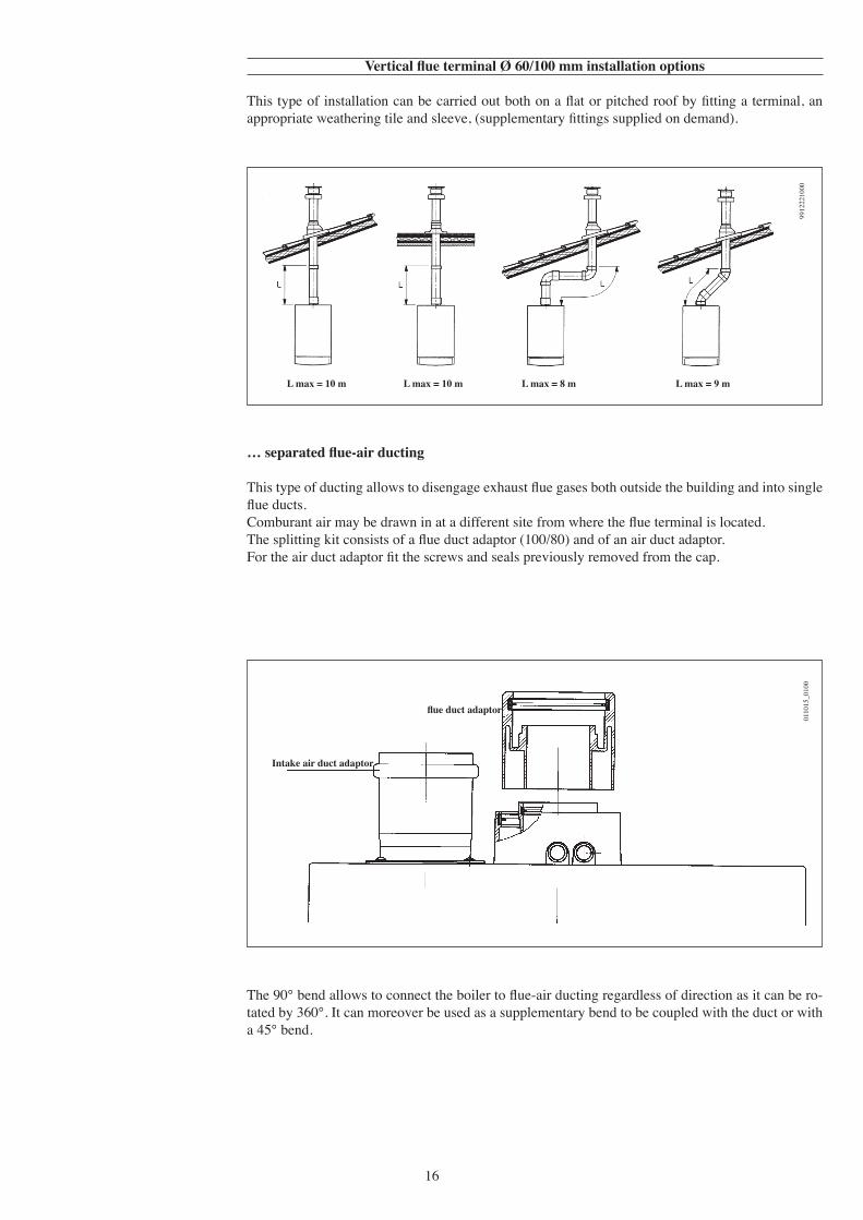
Vertical flue terminal Ø 60/100 mm installation options
This type of installation can be carried out both on a flat or pitched roof by fitting a terminal, an appropriate weathering tile and sleeve, (supplementary fittings supplied on demand).
L max = 10 m L max = 10 m L max = 9 mL max = 8 m
9912
2210
00
… separated flue-air ducting
This type of ducting allows to disengage exhaust flue gases both outside the building and into single flue ducts.Comburant air may be drawn in at a different site from where the flue terminal is located.The splitting kit consists of a flue duct adaptor (100/80) and of an air duct adaptor. For the air duct adaptor fit the screws and seals previously removed from the cap.
0110
15_0
100
flue duct adaptor
Intake air duct adaptor
The 90° bend allows to connect the boiler to flue-air ducting regardless of direction as it can be ro-tated by 360°. It can moreover be used as a supplementary bend to be coupled with the duct or with a 45° bend.
17
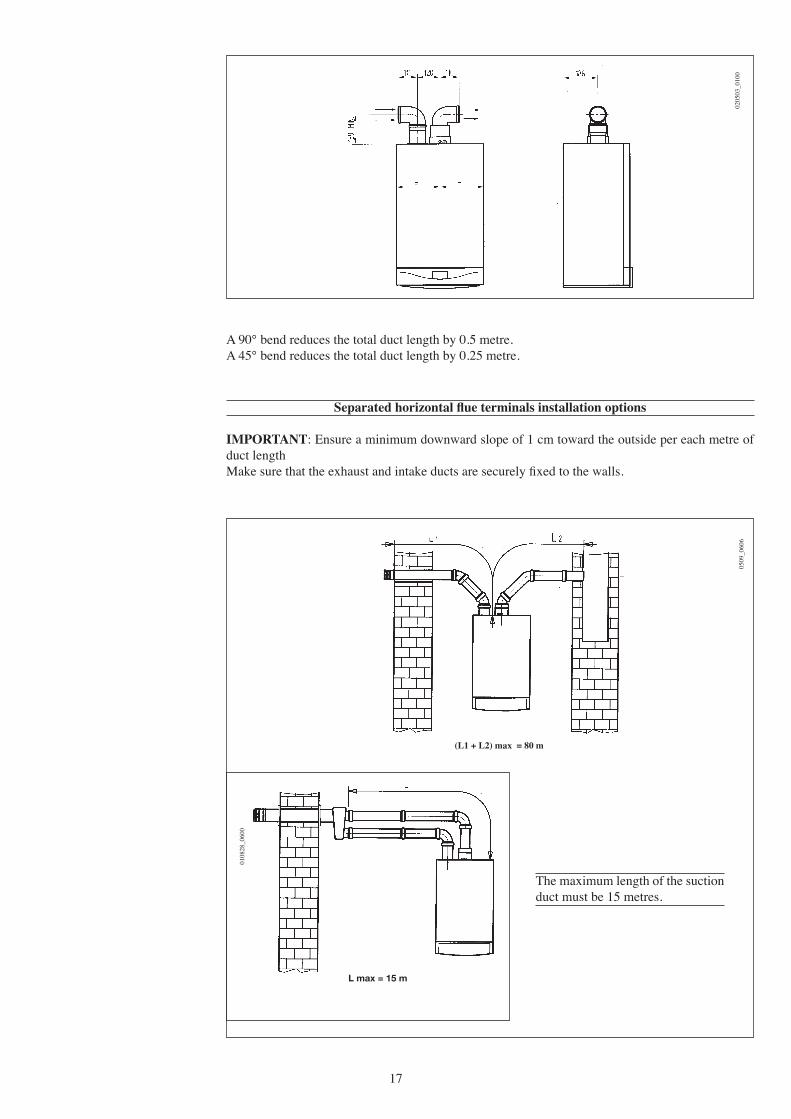
A 90° bend reduces the total duct length by 0.5 metre.A 45° bend reduces the total duct length by 0.25 metre.
0205
03_0
100
Separated horizontal flue terminals installation options
IMPORTANT: Ensure a minimum downward slope of 1 cm toward the outside per each metre of duct lengthMake sure that the exhaust and intake ducts are securely fixed to the walls.
(L1 + L2) max = 80 m
L max = 15 m
0509
_060
6
0108
28_0
600
The maximum length of the suction duct must be 15 metres.
18
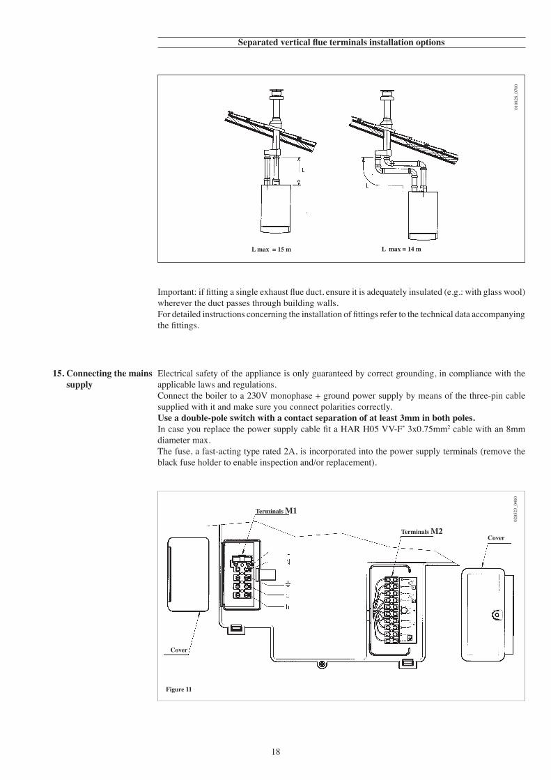
Separated vertical flue terminals installation options
Important: if fitting a single exhaust flue duct, ensure it is adequately insulated (e.g.: with glass wool) wherever the duct passes through building walls.For detailed instructions concerning the installation of fittings refer to the technical data accompanying the fittings.
L max = 14 mL max = 15 m
0108
28_0
700
Electrical safety of the appliance is only guaranteed by correct grounding, in compliance with the applicable laws and regulations.Connect the boiler to a 230V monophase + ground power supply by means of the three-pin cable supplied with it and make sure you connect polarities correctly.Use a double-pole switch with a contact separation of at least 3mm in both poles.In case you replace the power supply cable fit a HAR H05 VV-F ̓3x0.75mm2 cable with an 8mm diameter max.The fuse, a fast-acting type rated 2A, is incorporated into the power supply terminals (remove the black fuse holder to enable inspection and/or replacement).
15. Connecting the mains supply
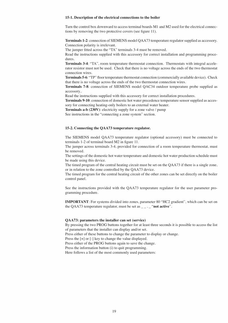
Figure 11
0205
23_0
400
Terminals M1
Terminals M2Cover
Cover
19
15-1. Description of the electrical connections to the boiler
Turn the control box downward to access terminal boards M1 and M2 used for the electrical connec-tions by removing the two protective covers (see figure 11).
Terminals 1-2: connection of SIEMENS model QAA73 temperature regulator supplied as accessory. Connection polarity is irrelevant.The jumper fitted across the “TA” terminals 3-4 must be removed.Read the instructions supplied with this accessory for correct installation and programming proce-dures.Terminals 3-4: “TA”, room temperature thermostat connection. Thermostats with integral accele-rator resistor must not be used. Check that there is no voltage across the ends of the two thermostat connection wires.Terminals 5-6: “TP” floor temperature thermostat connection (commercially available device). Check that there is no voltage across the ends of the two thermostat connection wires.Terminals 7-8: connection of SIEMENS model QAC34 outdoor temperature probe supplied as accessory..Read the instructions supplied with this accessory for correct installation procedures.Terminals 9-10: connection of domestic hot water precedence temperature sensor supplied as acces-sory for connecting heating-only boilers to an external water heater.Terminals a-b (230V): electricity supply for a zone valve / pumpSee instructions in the “connecting a zone system” section.
15-2. Connecting the QAA73 temperature regulator.
The SIEMENS model QAA73 temperature regulator (optional accessory) must be connected to terminals 1-2 of terminal board M2 in figure 11.The jumper across terminals 3-4, provided for connection of a room temperature thermostat, must be removed.The settings of the domestic hot water temperature and domestic hot water production schedule must be made using this device.The timed program of the central heating circuit must be set on the QAA73 if there is a single zone, or in relation to the zone controlled by the QAA73 device.The timed program for the central heating circuit of the other zones can be set directly on the boiler control panel.
See the instructions provided with the QAA73 temperature regulator for the user parameter pro-gramming procedure.
IMPORTANT: For systems divided into zones, parameter 80 “HC2 gradient”, which can be set on the QAA73 temperature regulator, must be set as _ _ . _ “not active”.
QAA73: parameters the installer can set (service)By pressing the two PROG buttons together for at least three seconds it is possible to access the list of parameters that the installer can display and/or set.Press either of these buttons to change the parameter to display or change.Press the [+] or [-] key to change the value displayed.Press either of the PROG buttons again to save the change.Press the information button (i) to quit programming.Here follows a list of the most commonly used parameters:

20
- fault messages
In the event of fault, the display panel on the QAA73 shows the flashing symbol . Press the infor-mation key ( ) to display the error code and a description of the fault (see table on paragraph 3.9).
Line no.
70
72
74
75
77
78
79
80
90
91
Default value
15
85
Light
On HC1
On
0
0
—.-
10 or 35
24 h/day
Range
2.5…40
25…85
Light, Heavy
on HC1on HC2on HC1+HC2 nil
On - off
0…360 min
0…360 min
2.5…40 —.- = not active
10 or 35…58
24 h/day TSP HC-1hTSP HCTSP DHW
Parameter
HC1 gradient Selection of central heating circuit temperature curve “kt”
HC1 max. output Central heating system maximum output temperature
Type of building
Room compensation Activation/deactivation of the influence of the room temperature. If it is deactivated, the outdoor temperature sensor must be installed.
Automatic adaptation of the temperature curve “kt” in relation to the room temperature.
Opt Start MaxMaximum time the boiler is switched on ahead of the timed program to optimise the temperature in the premises.
Opt Stop Max Maximum time the boiler is switched off ahead of the timed program to optimise the temperature in the premises.
HC2 gradient Selection of temperature curve “kt” of the HC2 central heating circuit of the low temperature zone if the SIEMENS AGU2.500 accessory is used.
DHW Red SetpMinimum temperature of the domestic domestic hot water DHW programSelection of the type of timed program for domestic hot water.24 h/day = always on PROG HC-1h = as HC1 central heating program less
one hour PROG HC = as central heating program PROG ACS = specific domestic hot water program
(see also program lines 30-36)
21
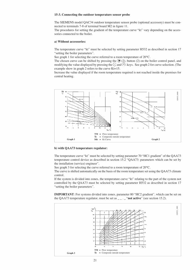
15-3. Connecting the outdoor temperature sensor probe
The SIEMENS model QAC34 outdoor temperature sensor probe (optional accessory) must be con-nected to terminals 7-8 of terminal board M2 in figure 11.The procedures for setting the gradient of the temperature curve “kt” vary depending on the acces-sories connected to the boiler.
a) Without accessories:
The temperature curve “kt” must be selected by setting parameter H532 as described in section 17 “setting the boiler parameters”.See graph 1 for selecting the curve referred to a room temperature of 20°C.The chosen curve can be shifted by pressing the (2), button (2) on the boiler control panel, and modifying the value displayed by pressing the and . keys. See graph 2 for curve selection. (The example show in graph 2 refers to the curve Kt=15.Increase the value displayed if the room temperature required is not reached inside the premises for central heating.
b) with QAA73 temperature regulator:
The temperature curve “kt” must be selected by setting parameter 70 “HC1 gradient” of the QAA73 temperature control device as described in section 15.2 “QAA73: parameters which can be set by the installation (service) engineer”.See graph 3 for selecting the curve referred to a room temperature of 20°C.The curve is shifted automatically on the basis of the room temperature set using the QAA73 climate control.If the system is divided into zones, the temperature curve “kt” relating to the part of the system not controlled by the QAA73 must be selected by setting parameter H532 as described in section 17 “setting the boiler parameters”.
IMPORTANT: For systems divided into zones, parameter 80 “HC2 gradient”, which can be set on the QAA73 temperature regulator, must be set as _ _ . _ “not active” (see section 15.2).
Graph 1 Graph 2
TM = Flow temperature Te = Composite outside temperature Sth = Kt Curve
Graph 3TM = Flow temperature Te = Composite outside temperature
0205
23_0
600
0205
23_1
000
22
c) with AGU2.500 for control of a low temperature system:
Refer to the instructions provided with the AGU2.500 accessories for connection and control of a low temperature zone.
c) with AGU2.500 for control of a low temperature system:
Refer to the instructions provided with the AGU2.500 accessories for connection and control of a low temperature zone.
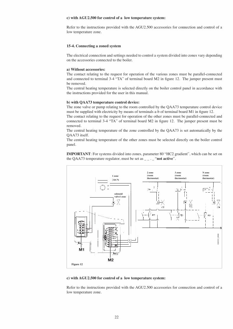
15-4. Connecting a zoned system
The electrical connection and settings needed to control a system divided into zones vary depending on the accessories connected to the boiler.
a) Without accessories:The contact relating to the request for operation of the various zones must be parallel-connected and connected to terminal 3-4 “TA” of terminal board M2 in figure 12. The jumper present must be removed.The central heating temperature is selected directly on the boiler control panel in accordance with the instructions provided for the user in this manual.
b) with QAA73 temperature control device:The zone valve or pump relating to the room controlled by the QAA73 temperature control device must be supplied with electricity by means of terminals a-b of terminal board M1 in figure 12.The contact relating to the request for operation of the other zones must be parallel-connected and connected to terminal 3-4 “TA” of terminal board M2 in figure 12. The jumper present must be removed.The central heating temperature of the zone controlled by the QAA73 is set automatically by the QAA73 itself.The central heating temperature of the other zones must be selected directly on the boiler control panel.
IMPORTANT: For systems divided into zones, parameter 80 “HC2 gradient”, which can be set on the QAA73 temperature regulator, must be set as _ _ . _ “not active”.
Figure 12
0205
23_0
900
N zone(room thermostat)
3 zone(room thermostat)
2 zone(room thermostat)
1 zone
solenoid valve1 zone
M1
M2

23
15-5. Connecting a remote water heater (for LUNA HT 1.120 - 1.240 - 1.280 models)
LUNA HT 1.120 - 1.240 - 1.280 models are designed for connection of a remote water heater since they are fitted in the factory with a motor-operated three-way valve.Make the water connections to the water heater as shown in figure 13.Connect the NTC domestic hot water priority probe supplied as an accessory to terminals 9-10 of terminal board M2 in figure 11, first removing the electrical heating element fitted.The sensor element of the NTC probe must be fitted into the well provided on the water heater.The domestic hot water temperature can be set and the timed domestic hot water program selected directly on the boiler control panel as described in the instructions provided for the user in this manual.
Figure 13
0207
_090
4
KEY
UB: domestic hot water heater unit (storage tank)UR: central heating unitV3V: three-way valve M2: connection terminal boardSB: domestic hot water heater priority sensor MR: central heating deliveryMB: domestic hot water heater deliveryRR: central heating/boiler return
24
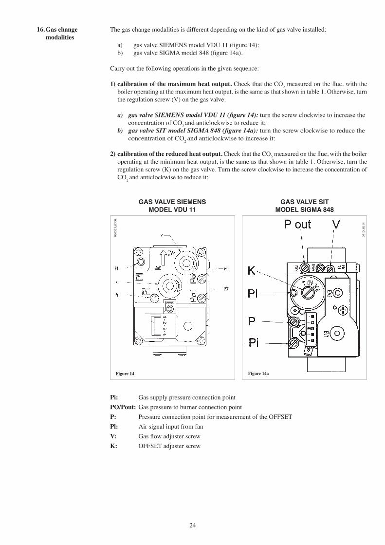
16. Gas change modalities
The gas change modalities is different depending on the kind of gas valve installed:
a) gas valve SIEMENS model VDU 11 (figure 14); b) gas valve SIGMA model 848 (figure 14a).
Carry out the following operations in the given sequence:
1) calibration of the maximum heat output. Check that the CO2 measured on the flue, with the boiler operating at the maximum heat output, is the same as that shown in table 1. Otherwise, turn the regulation screw (V) on the gas valve.
a) gas valve SIEMENS model VDU 11 (figure 14): turn the screw clockwise to increase the concentration of CO2 and anticlockwise to reduce it;
b) gas valve SIT model SIGMA 848 (figure 14a): turn the screw clockwise to reduce the concentration of CO2 and anticlockwise to increase it;
2) calibration of the reduced heat output. Check that the CO2 measured on the flue, with the boiler operating at the minimum heat output, is the same as that shown in table 1. Otherwise, turn the regulation screw (K) on the gas valve. Turn the screw clockwise to increase the concentration of CO2 and anticlockwise to reduce it;
0310
_011
4
Figure 14a
Pi: Gas supply pressure connection pointPO/Pout: Gas pressure to burner connection pointP: Pressure connection point for measurement of the OFFSETPl: Air signal input from fanV: Gas flow adjuster screwK: OFFSET adjuster screw
Figure 14
0205
23_0
700
GAS VALVE SIEMENS MODEL VDU 11
GAS VALVE SIT MODEL SIGMA 848

25
0204
29_0
400
Figure 15
To simplify calibration of the gas valve, the “calibration function” can be set directly on the boiler control panel by proceeding as follows:1) Press the keys (2-3) together until the display shows the pointer “ ” alongside the symbol
(about 6 seconds). 2) Press the keys to set the fan speed at the minimum and maximum heat output (%PWM); N.b - to set the minimum and maximum heat output quickly, press the keys respectively;3) press either of the two keys to exit the function.
LUNA HT 1.240 G20 - 2H - 20 mbar G31 - 3P - 37 mbar LUNA HT 280 CO2 max. heat output 8,7% 10% CO2 min. heat output 8,4% 9,5% Gas nozzle 7,5 mm 7,5 mm
Table 1c
Table 1b
LUNA HT 330 G20 - 2H - 20 mbar G31 - 3P - 37 mbar LUNA HT 1.280 CO2 max. heat output 8,7% 10% CO2 min. heat output 8,4% 9,8% Gas nozzle 12,0 mm 12,0 mm
Table 1a
LUNA HT 330 Gas consumption at 15 °C G20 - 2H - 20 mbar G31 - 3P - 37 mbar 1013 mbar PCI 34.02 MJ/m3 46.3 MJ/kg Consumption at max. heat output 3.59 m3/h 2.64 kg/h Consumption at min. heat output 1.06 m3/h 0.78 kg/h
Table 2a
IMPORTANT: in the case of conversion from natural gas to propane (LPG), the following operations must be performed before calibrating the gas valve as illustrated above:• Turn adjuster screw (V) on the gas valve through the number of complete revolutions specified in
table 3 or 3.1;• On the control panel display set ignition power parameters H608 and H611. The values to be input
are given in table 3 or 3.1. The programming methods are described in chapter 17;
LUNA HT 1.120 G20 - 2H - 20 mbar G31 - 3P - 37 mbar CO2 max. heat output 8,7% 10% CO2 min. heat output 8,4% 9,5% Gas nozzle 4,0 mm 4,0 mm

26
LUNA HT 280 Gas consumption at 15 °C G20 - 2H - 20 mbar G31 - 3P - 37 mbar 1013 mbar PCI 34.02 MJ/m3 46.3 MJ/kg Consumption at max. heat output 3.06 m3/h 2.25 kg/h Consumption at min. heat output 0,95 m3/h 0.70 kg/h
Table 2b
LUNA HT 1.240 Gas consumption at 15 °C G20 - 2H - 20 mbar G31 - 3P - 37 mbar 1013 mbar PCI 34.02 MJ/m3 46.3 MJ/kg Consumption at max. heat output 2.61 m3/h 1.92 kg/h Consumption at min. heat output 0.74 m3/h 0.54 kg/h
Table 2d
LUNA HT 1.120 Gas consumption at 15 °C G20 - 2H - 20 mbar G31 - 3P - 37 mbar 1013 mbar PCI 34.02 MJ/m3 46.3 MJ/kg Consumption at max. heat output 1.31 m3/h 0.96 kg/h Consumption at min. heat output 0,42 m3/h 0,31 kg/h
Table 2e
LUNA HT 1.280 Gas consumption at 15 °C G20 - 2H - 20 mbar G31 - 3P - 37 mbar 1013 mbar PCI 34.02 MJ/m3 46.3 MJ/kg Consumption at max. heat output 3.06 m3/h 2.25 kg/h Consumption at min. heat output 1,06 m3/h 0.78 kg/h
Table 2c
CLOCKWISE Parameters 608 Parameters 611 Gas boiler model regulation screw (%) (rpm) (V) turns Gas G20 Gas G31 Gas G20 Gas G31
LUNA HT 330 3 50 35 4200 3500
LUNA HT 280 4 55 35 4600 4000
LUNA HT 1.280 3 50 35 4200 3500
LUNA HT 1.240 2 55 35 4600 4000
LUNA HT 1.120 3/4 40 40 3900 3350
GAS VALVE SIT MOD. SIGMA 848
ANTICLOCKWISE Parameters 608 Parameters 611 Gas boiler model regulation screw (%) (rpm) (V) turns Gas G20 Gas G31 Gas G20 Gas G31
LUNA HT 330 4 50 35 4200 3500
LUNA HT 280 2 55 35 4600 4000
LUNA HT 1.280 4 50 35 4200 3500
LUNA HT 1.240 2 55 35 4600 4000
LUNA HT 1.120 1 40 40 3900 3350
GAS VALVE SIEMENS MOD. DVU 11
Table 3
Table 3.1

27
Parameter N.
H90
H91
H93
H505
H507
H516
H532
H533
H536
H544
H545
H552
H584
H602
H603
H615
H641
Description
Setting for domestic hot water reduced temperature (°C) S.H.W. (Sanitary Hot Water) programSelecting the sanitary hot water program:1 = S.H.W. production on 24 hours a day;0 = special program for sanitary hot water (program lines 31...36).If the preheating function has been enabled (parameter H602=1440):1 = preheating on 24 hours a day;0 = preheating controlled by special S.H.W. program (program lines 31...36).
Only for plate type heat exchangers.Economy function: allows the user to disable the preheating function while leaving sanitary hot water production enabled (key 1 - figure 1; a line appears under the
symbol).0 = disabled1 = enabledNote: The economy function can only be used if the preheating function is enabled (parameter H602 = 1440).
Maximum temperature (°C) of the central heating circuit HC1 corresponding to:- the main circuit in systems with just one zone;- the circuit of the zone where the QAA73 temperature control device is installed
in case of systems with more than one high-temperature zone;- the high temperature zone circuit in mixed systems and if the SIEMENS
AGU2.500 accessory is used.
Maximum temperature (°C) of the central heating circuit HC2 of a system with more than one zone, corresponding to the circuit of the low-temperature zone if the SIEMENS AGU2.500 accessory is used.
Automatic Summer / Winter switching temperature (°C).
Selection of temperature curve of central heating circuit HC1 (see Graph 1)
Selection of temperature curve of central heating circuit HC2 (see Graph 1)
Selection of central heating power (N. of fan rpm)
Pump post-circulation time in central heating mode (min)
Burner operating pause time between two start-ups (s)
Hydraulic system setting (see instructions provided with the SIEMENS AGU2.500 accessory)
Pump / three-way valve anti-blocking operating time (s)
Heat exchanger preheating holding time after operation in domestic hot water mode (min)
Heat exchanger preheating holding time after operation in central heating mode (min)
Programmable function:- “0” electricity supply to zone pump / valve and use of the SIEMENS AGU2.500
accessory;- “1” electricity supply to a remote LPG gas valve;- “5” electricity supply to zone pump / valve in the absence of the SIEMENS
AGU2.500 accessory.Only one of these functions can be selected.
Fan post-purge interval (s)
Factory setting
10 or 35
1
0
80
70
20
15
15
See table 4
3
180
See table 4
10
0
0
5
10
The boiler parameters may only be modified by professionally qualified staff proceeding as follows:a) press the , keys on the boilerʼs front panel together for about 3 s until the parameter H90 appears
on the display;b) press the keys to select the parameter for modification;c) press the and keys to modify the parameter;d) press the key to exit the programming function.e) when programming is finished, warning message E183 will blink for 3 seconds approx. If the warning continues to blink or if other warnings are displayed, press the reset button When warning message E153 appears, press the reset button a second time.The following are the parameters generally used:
17. Setting the boiler parameters
28
The boiler has been designed in full compliance with European reference standards and in particular is equipped with the following
• Overheat thermostat Thanks to a sensor placed on the heating flow, this thermostat interrupts the gas flow to the main
burner in case the water contained in the primary system has overheated. Under these conditions the boiler locks out and you can only repeat the ignition procedure by pressing the reset button on the boiler after you have remedied the cause of the trip.
It is forbidden to disenable this safety device
• Flue thermostat This device, positioned on the flue inside the boiler, interrupts the flow of gas to the burner if the
temperature exceeds 90 °C. After verifying the cause of the trip, press the reset button positioned on the thermostat itself, then press the release button on the boiler.
It is forbidden to disenable this safety device
• Flame ionization detector The flame sensing electrode guarantees safety of operation in case of gas failure or incomplete
interlighting of the main burner. Under such conditions the boiler is blocked. You must press the reset button on the boiler to restore the normal operating conditions.
• Hydraulic differential pressure sensor This pressure sensor, fitted on the hydraulic assembly, allows the main burner to light provided
the pump head is as required and protects the flue-water exchanger from possible lacks of water or blockings of the pump.
• Supplementary running of the pump The electronically-controlled supplementary running of the pump lasts 3 minutes, when the boiler
is in the central heating mode, after the burner has switched off due to a room thermostat inter-vention.
• Frost protection device Boilers electronic management includes a “frost protection” function in the central heating system
which operates the burner to reach a heating flow temperature of 30°C when the system heating flow temperature drops below 5 °C.
This function is enabled as long as the boiler is connected to the a.c. power and gas supplies and the pressure in the system is as specified.
• Pump-blocking prevention In case there is no call for heat either from the central heating system or from the DHW system
for 24 hours on end the pump will automatically switch on for 10 seconds.
• 3-way antiblocking valve If there is no heat demand for a period of 24 hours the 3-way valve switches completely. This function is enabled if the electrical supply to the boiler is on.
• Hydraulic safety valve (heating circuit) This device is set to 3 bar and is used for the heating circuit
The safety valve should be connected to a siphoned drain. Use as a means of draining the heating circuit is strictly prohibited.
18. Control and operation devices
Parameter N LUNA HT 280 LUNA HT 330 LUNA HT 1.120 LUNA HT 1.240 LUNA HT 1.280 H536 4900 4550 5850 5900 4550 H552 38 38 35 35 35
If the electronic circuit board is replaced, make sure that the parameters set are those specific to the boiler model, as indicated in the documentation available from the authorised Service Centre.
Table 4
29
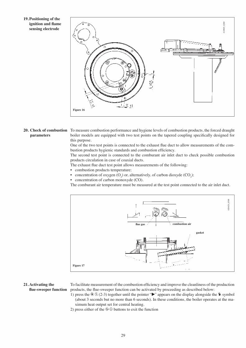
19. Positioning of the ignition and flame sensing electrode
Figure 16
0109
05_0
200
To measure combustion performance and hygiene levels of combustion products, the forced draught boiler models are equipped with two test points on the tapered coupling specifically designed for this purpose.One of the two test points is connected to the exhaust flue duct to allow measurements of the com-bustion products hygienic standards and combustion efficiency.The second test point is connected to the comburant air inlet duct to check possible combustion products circulation in case of coaxial ducts.The exhaust flue duct test point allows measurements of the following:• combustion products temperature;• concentration of oxygen (O2) or, alternatively, of carbon dioxyde (CO2);• concentration of carbon monoxyde (CO).The comburant air temperature must be measured at the test point connected to the air inlet duct.
20. Check of combustion parameters
Figure 17
0204
29_0
300
flue gas combustion air
gasket
To facilitate measurement of the combustion efficiency and improve the cleanliness of the production products, the flue-sweeper function can be activated by proceeding as described below:1) press the (2-3) together until the pointer “ ” appears on the display alongside the symbol
(about 3 seconds but no more than 6 seconds). In these conditions, the boiler operates at the ma-ximum heat output set for central heating.
2) press either of the buttons to exit the function
21. Activating the flue-sweeper function

30
0204
29_0
200
Figure 18
This is a high static head pump fit for installation on any type of single or double-pipe heating systems. The air vent valve incorporated in the pump allows quick venting of the heating system.
22. Output / pump head performances
PUM
P H
EAD
mH
2O
OUTPUT l/hh
0205
23_1
100
Graph 4
The stainless steel plate-type DHW heat exchanger is easily disassembled with a screwdriver by operating as described below:
• drain, if possible, only the boiler system, through the drain tap;• drain the DHW system from water;• remove the circulation pump;• remove the two srews (right in front of you) securing the DHW heat exchanger and pull it off its
seat (Figure 19).
23. How to disasseble the DHW heat exchanger (LUNA HT 280 - HT 330)
Figure 19 DHW heat exchanger securing screws
flow sensing securing nut
0204
29_0
100
31
To purge the exchanger and/or the DHW system we suggest the use of Cillit FFW-AL or Beckinser HF-AL.
For specific areas where water hardness exceeds 20°F (1°F = 10 mg of calcium carbonate per one litre of water) we recommend you install a polyphosphate metering device - complying with the applicable regulations - in the cold water inlet pipework.
24. Cleaning the cold water filter
(LUNA HT 280 - HT 330)
The boiler is equipped with a cold water filter placed on the hydraulic assembly. To clean it do the following:
• drain the DHW system from water.• unscrew the nut on the flow sensing assembly (Figure 19).• pull out the flow sensing device and its filter.• remove the impurities.
Important: in the event of replacements and/or cleaning of the O-rings on the hydraulic unit, do not use oil or grease as lubricant but exclusively Molykote 111.
To ensure the boiler operates at peak efficiency, the following checks must be performed every year:• check on the appearance and tightness of the gas and combustion circuit gaskets;• check on the condition and position of the ignition and flame sensing electrodes (see section
19);• check on the condition of the burner and its fixing to the aluminium flange;• check for any dirt in the combustion chamber. Use a vacuum-cleaner for this cleaning opera-
tion,• check that the gas valve is calibrated correctly (see section 16);• check if the siphon is dirty;• check on the central heating system pressure.• check on the expansion vessel pressure.
25. Annual service
32
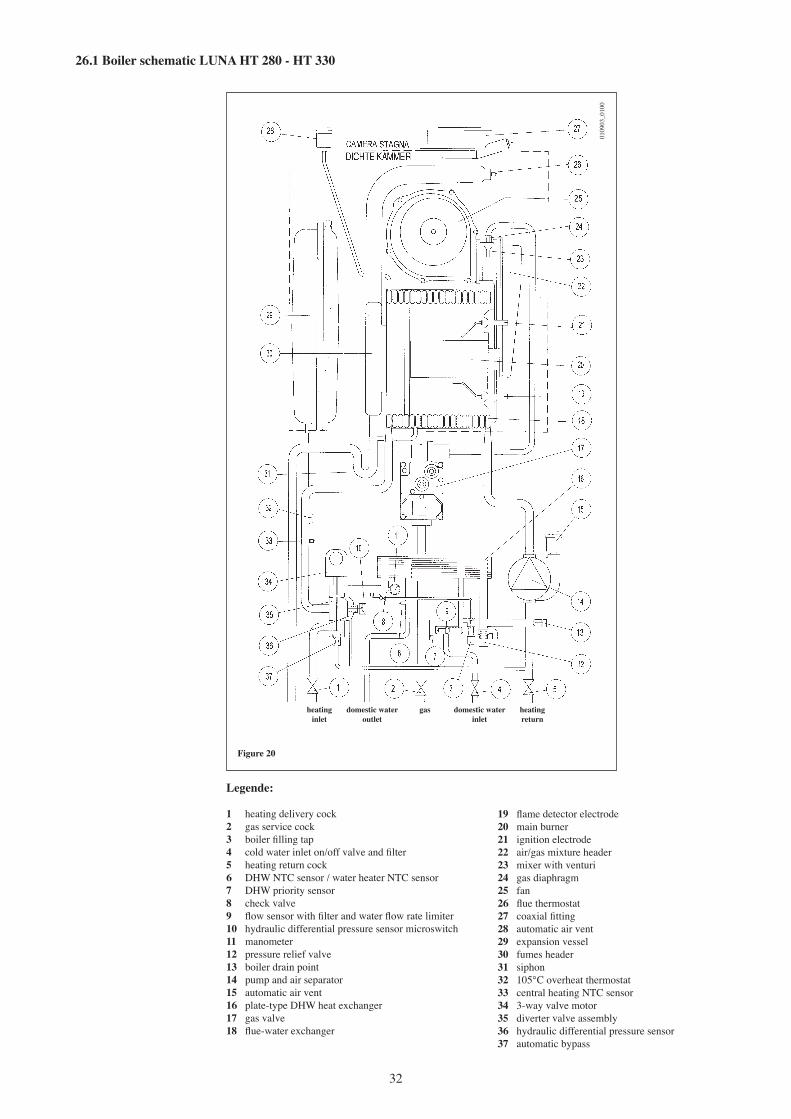
26.1 Boiler schematic LUNA HT 280 - HT 330
Legende:
1 heating delivery cock2 gas service cock3 boiler filling tap4 cold water inlet on/off valve and filter5 heating return cock6 DHW NTC sensor / water heater NTC sensor 7 DHW priority sensor8 check valve9 flow sensor with filter and water flow rate limiter10 hydraulic differential pressure sensor microswitch11 manometer12 pressure relief valve13 boiler drain point14 pump and air separator15 automatic air vent16 plate-type DHW heat exchanger17 gas valve18 flue-water exchanger
19 flame detector electrode20 main burner21 ignition electrode22 air/gas mixture header23 mixer with venturi24 gas diaphragm25 fan26 flue thermostat27 coaxial fitting28 automatic air vent29 expansion vessel30 fumes header31 siphon32 105°C overheat thermostat33 central heating NTC sensor34 3-way valve motor35 diverter valve assembly36 hydraulic differential pressure sensor37 automatic bypass
Figure 20
0109
03_0
100
heating domestic water gas domestic water heating inlet outlet inlet return
33
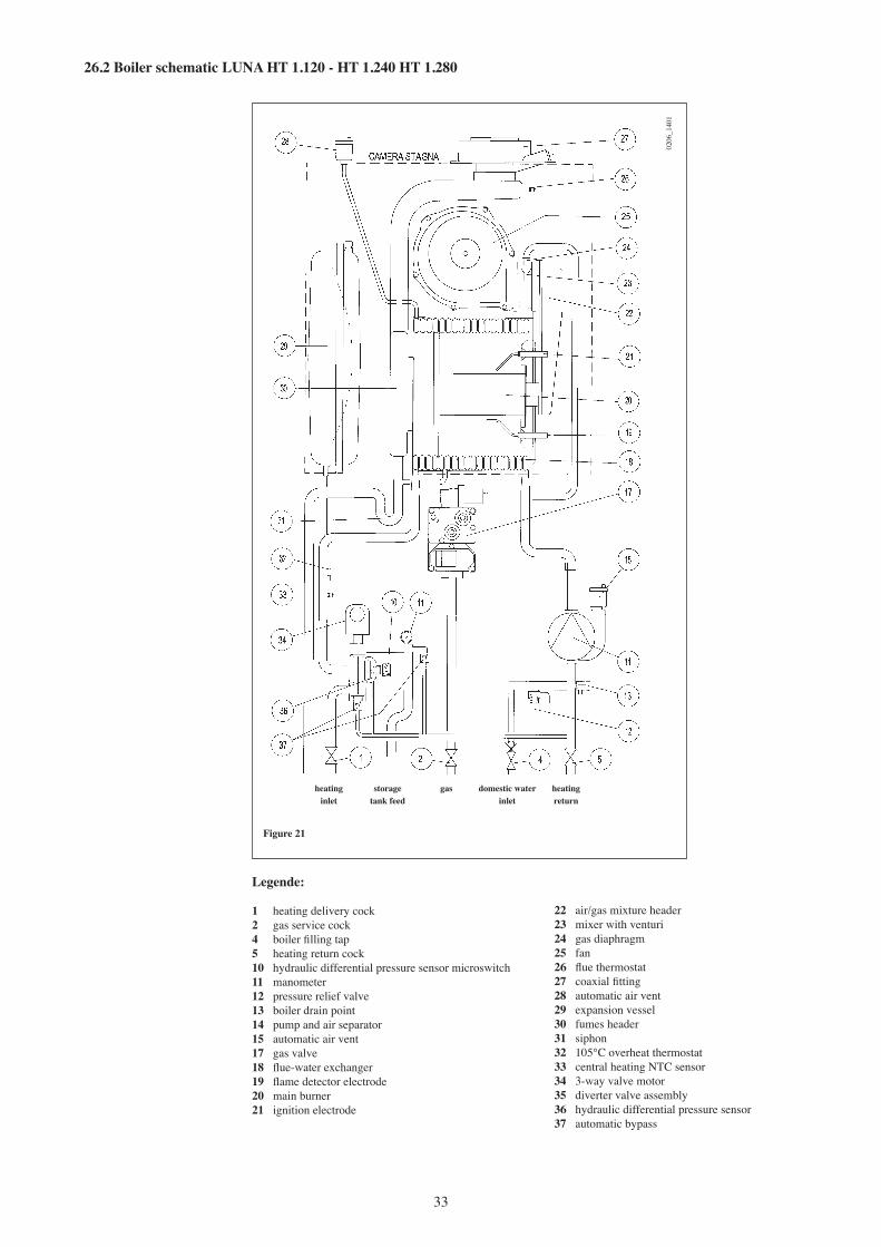
26.2 Boiler schematic LUNA HT 1.120 - HT 1.240 HT 1.280
Figure 21
0206
_140
1
heating storage gas domestic water heating inlet tank feed inlet return
Legende:
1 heating delivery cock2 gas service cock4 boiler filling tap5 heating return cock10 hydraulic differential pressure sensor microswitch11 manometer12 pressure relief valve13 boiler drain point14 pump and air separator15 automatic air vent17 gas valve18 flue-water exchanger19 flame detector electrode20 main burner21 ignition electrode
22 air/gas mixture header23 mixer with venturi24 gas diaphragm25 fan26 flue thermostat27 coaxial fitting28 automatic air vent29 expansion vessel30 fumes header31 siphon32 105°C overheat thermostat33 central heating NTC sensor34 3-way valve motor35 diverter valve assembly36 hydraulic differential pressure sensor37 automatic bypass
34
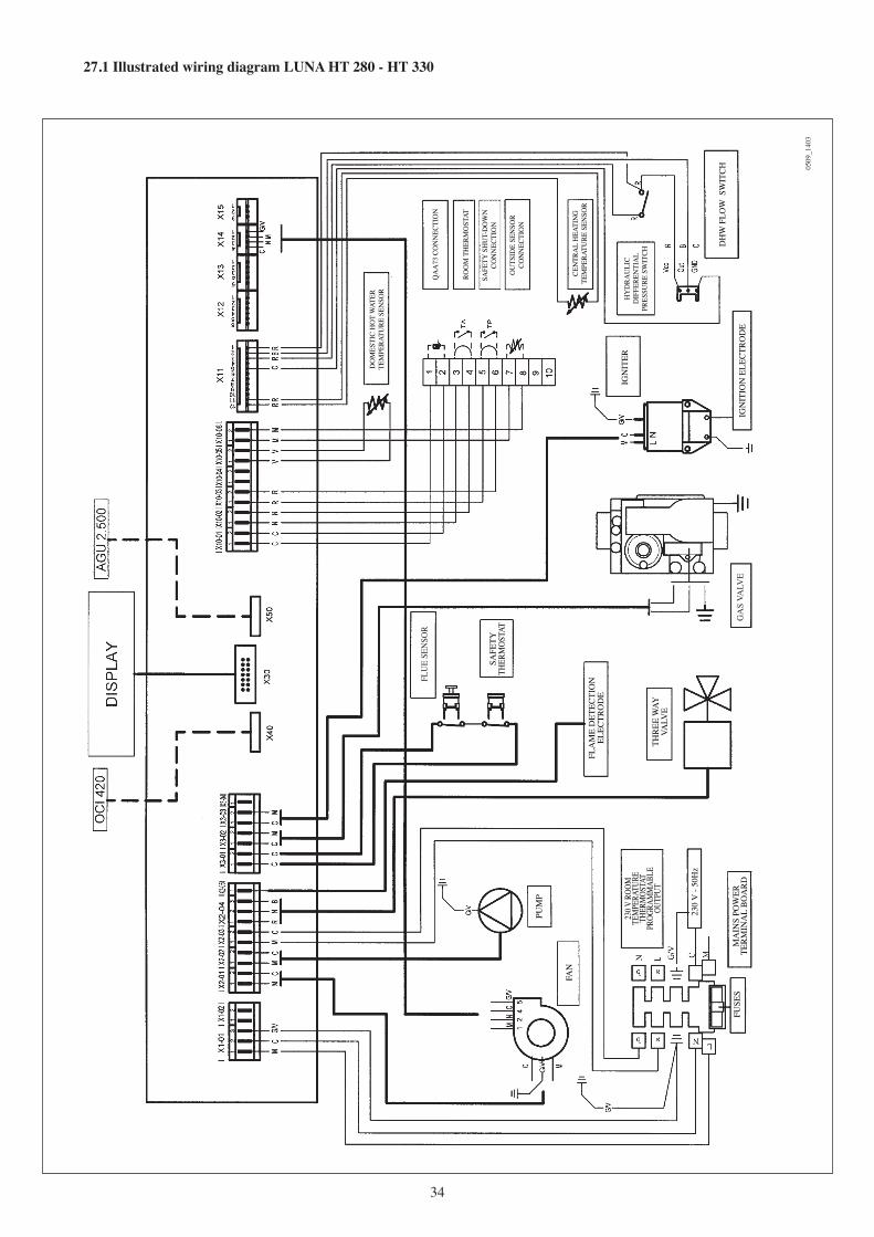
27.1 Illustrated wiring diagram LUNA HT 280 - HT 330
FAN
FUSE
S
SAFE
TY
THER
MOS
TAT
FLA
ME
DET
ECTI
ON
EL
ECTR
OD
E
GA
S VA
LVE
IGN
ITER
IGN
ITIO
N E
LEC
TRO
DE
DO
MES
TIC
HO
T W
ATER
TE
MPE
RATU
RE S
ENSO
R
THR
EE W
AY
VALV
E
PUM
P
FLU
E SE
NSO
R
230
V -
50H
z
QA
A73
CO
NN
ECTI
ON
ROO
M T
HER
MO
STAT
SAFE
TY S
HU
T-D
OW
NCO
NN
ECTI
ON
OU
TSID
E SE
NSO
RCO
NN
ECTI
ON
CEN
TRA
L H
EATI
NG
TE
MPE
RATU
RE S
ENSO
R
HY
DRA
ULI
C D
IFFE
REN
TIA
L PR
ESSU
RE S
WIT
CH
MA
INS
POW
ER
TER
MIN
AL
BO
AR
D
DH
W F
LOW
SW
ITCH 05
09_1
403
230 V
ROO
M
TEM
PERA
TURE
TH
ERM
OSTA
TPR
OGRA
MM
ABLE
OU
TPUT
35
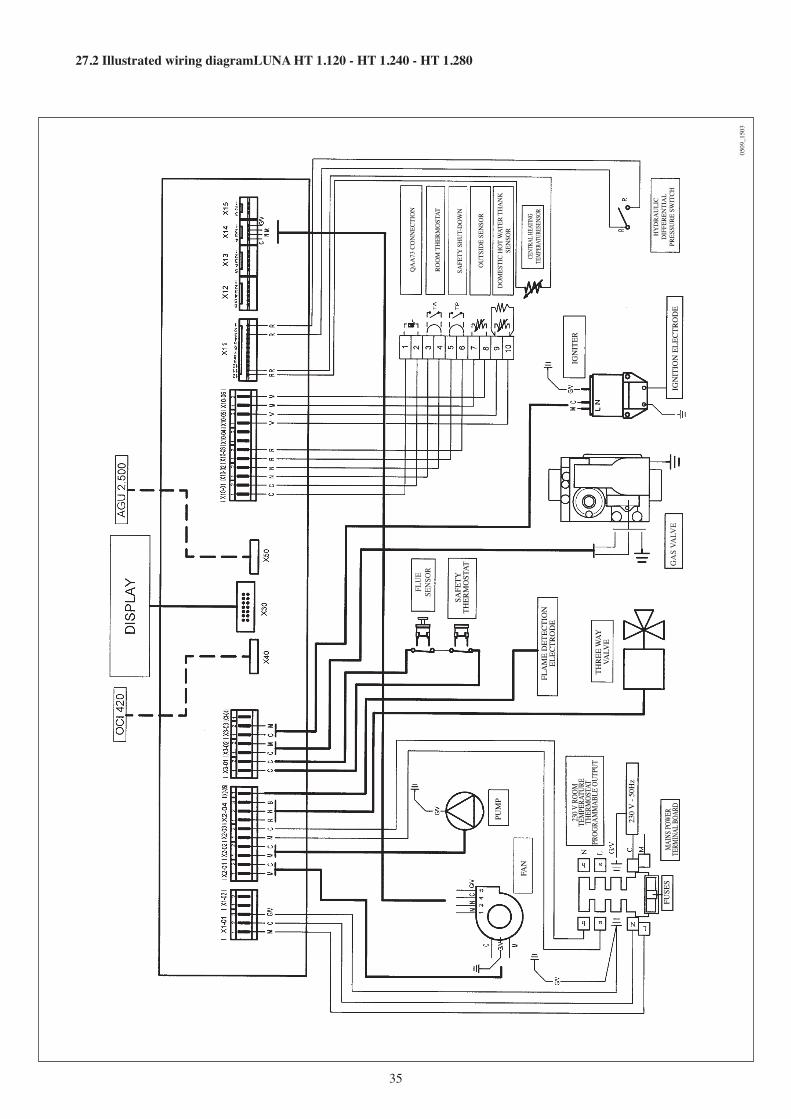
27.2 Illustrated wiring diagramLUNA HT 1.120 - HT 1.240 - HT 1.280
FAN
FUSE
S
SAFE
TY
THER
MO
STAT
FLA
ME
DET
ECTI
ON
EL
ECTR
OD
E
GA
S VA
LVE
IGN
ITER
IGN
ITIO
N E
LEC
TRO
DE
THR
EE W
AY
VALV
E
PUM
P
FLU
E SE
NSO
R
QA
A73
CO
NN
ECTI
ON
ROO
M T
HER
MO
STAT
SAFE
TY S
HU
T-D
OW
N
OU
TSID
E SE
NSO
R
DO
MES
TIC
HO
T W
ATER
TH
AN
K
SEN
SOR
CENT
RAL H
EATI
NG
TEM
PERA
TURE
SENS
OR
HY
DRA
ULI
C D
IFFE
REN
TIA
L PR
ESSU
RE S
WIT
CH
230 V
ROO
MTE
MPE
RATU
RE
THER
MOS
TAT
PROG
RAM
MAB
LE O
UTPU
T
230
V -
50H
z
MAI
NS PO
WER
TE
RMIN
AL B
OARD
0509
_150
3

BAXI S.p.A.36061 BASSANO DEL GRAPPA (VI) ITALIA
Via Trozzetti, 20Tel. 0424 - 517111
Telefax 0424/38089 code C603677
BAXI S.p.A., in its commitment to constantly improve its products, reserves the right to alter the specifications contained herein at any time and without previous warning. These Instructions are only meant to provide consumers with use information and under no circumstance should they be construed as a contract with a third party.
Boiler model LUNA HT 280 330 1.120 1.240 1.280Category II2H3P II2H3P II2H3P II2H3P II2H3P
DHW rated heat input kW 28,9 34 - - -CH rated heat input kW 24,7 28,9 12,4 24,7 28,9Reduced heat input kW 9 9,7 4 7 9,7DHW rated heat output kW 28 33 - - - kcal/h 24.080 28.380 - - -CH rated heat output 75/60°C kW 24 28 12 24 28 kcal/h 20.640 24.080 10.320 20.640 24.080CH rated heat output 50/30°C kW 25,9 30,3 13 25,9 30,3 kcal/h 22.270 26.060 11.180 22.270 26.060Rated heat output 75/60°C kW 8,7 9.4 3,9 6.8 9.4 kcal/h 7.480 8.090 3.350 5.850 8.090Rated heat output 50/30°C kW 9,5 10.2 4,2 7.4 10.2 kcal/h 8.170 8.770 3.610 6.360 8.770Useful efficiency according to 92/42/CEE directive — ★★★★ ★★★★ ★★★★ ★★★★ ★★★★Central heating system max. pressure bar 3 3 3 3 3Expansion vessel capacity l 8 10 8 8 10Expansion vessel pressure bar 0,5 0,5 0,5 0,5 0,5DHW system max. pressure bar 8 8 - - -DHW system min. dynamic pressure bar 0,2 0,2 - - -DHW system min. output l/min 2,5 2,5 - - -DHW production at ∆T=25 °C l/min 16,1 18,9 - - -DHW production at ∆T=35 °C l/min 11,5 13,5 - - -Specific output (*)“D” l/min 12,9 15,3 - - -Heating circuit temperature range °C 25÷80 25÷80 25÷80 25÷80 25÷80Domestic hot water temperature range °C 35÷60 35÷60 - - -Type — C13 - C33 - C43 - C53 - C63 - C83 - B23 Concentric flue duct diameter mm 60 60 60 60 60Concentric air duct diameter mm 100 100 100 100 1002-pipe flue duct diameter mm 80 80 80 80 802-pipe air duct diameter mm 80 80 80 80 80Max. flue mass flow rate kg/s 0,014 0,016 0,006 0,012 0,014Min. flue mass flow rate kg/s 0,004 0,005 0,002 0,003 0,005Max. flue temperature °C 75 75 73 73 75NOx class — 5 5 5 5 5 Type of gas used — G20 G20 G20 G20 G20 — G31 G31 G31 G31 G31Natural gas feeding pressure mbar 20 20 20 20 20Propane gas feeding pressure mbar 37 37 37 37 37 Power supply voltage V 230 230 230 230 230Power supply frequency Hz 50 50 50 50 50Rated power supply W 155 160 145 150 155Net weight kg 45,5 46,5 44 45 46Dimensions height mm 763 763 763 763 763 width mm 450 450 450 450 450 depth mm 354 354 354 354 354Protection-limit against humidity and water leakages (**) IPX5D IPX5D IPX5D IPX5D IPX5D (*) according to EN 625 (**) according to EN 60529
28. Technical data
Ed. 3 - 12/05