Wall-mounted compact indirect heat interface unit1 Wall-mounted compact indirect heat interface unit...
16
1 Wall-mounted compact indirect heat interface unit SATK30 series INSTRUCTIONS FOR INSTALLATION, COMMISSIONING AND MAINTENANCE CONTENTS Safety instructions Dimensions Technical specifications Installation Commissioning Electronic regulator SATK30103HE SATK30105HE Electric connections Safety and alarms Troubleshooting 2 3 4 6 7 9 10 11 12 13 Maintenance 14 Function The SATK series HIU allows independent control of heat regulation and domestic hot water production within centralised heating systems or served by district heating networks. Product range SATK30103HE Indirect wall-mounted compact HIU for instantaneous domestic hot water production, power capacity 40 kW. SATK30105HE Indirect wall-mounted compact HIU for instantaneous domestic hot water production, power capacity 65 kW. 78232.01EN www.caleffi.com Commissioning checklist 16 Operating cycles 8
Transcript of Wall-mounted compact indirect heat interface unit1 Wall-mounted compact indirect heat interface unit...
1
Wall-mounted compact indirect heat interface unit
SATK30 series
INSTRUCTIONS FOR INSTALLATION, COMMISSIONING AND MAINTENANCE
CONTENTS
Safety instructions
DimensionsTechnical specifications
Installation
Commissioning
Electronic regulator
SATK30103HE
SATK30105HE
Electric connections
Safety and alarms
Troubleshooting
2
3
4
6
7
9
10
11
12
13
Maintenance
14
Function
The SATK series HIU allows independent control of heat regulation anddomestic hot water production within centralised heating systems orserved by district heating networks.
Product range
SATK30103HE Indirect wall-mounted compact HIU forinstantaneous domestic hot water production, power capacity 40 kW.
SATK30105HE Indirect wall-mounted compact HIU forinstantaneous domestic hot water production,power capacity 65 kW.
78232.01EN
www.caleffi.com
Commissioning checklist 16
Operating cycles 8

2
WARNINGSThese instructions must be read and understood before installing and maintaining the device.IMPORTANT! FAILURE TO FOLLOW THESE INSTRUCTIONS COULD RESULT IN A SAFETY HAZARD!
1 The device must be installed, commissioned and maintained by qualified technical personnel in accordance with national regulations and/or relevant localrequirements.
2 If the device is not installed, pre-run checked and maintained correctly in accordance with the instructions provided in this manual, it may not work properly andmay endanger the user.
3 Clean the pipes of any particles, rust, incrustations, limescale, welding slag and any other contaminants. The hydraulic circuit must be clean. 4 Make sure that all connection fittings are watertight.5 When connecting water pipes, make sure that threaded connections are not mechanically overstressed. Over time this could result in breakage, with water leakscausing damage and/or injury.
6 Water temperatures higher than 50°C may cause severe burns. When installing, commissioning and maintaining the device, take the necessary precautions sothat these temperatures will not be hazardous for people.
7 In the case of particularly hard or impure water, the device must be fitted for filtering and treating the water before it enters the device, in accordance with currentlegislation. Otherwise the device may be damaged and will not work properly.
8 Any use of the device other than its intended use is prohibited.9 Any combination of the device with other system components must be made taking the operational characteristics of both units into consideration. 10 An incorrectcoupling could compromise operation of the device and/or system.
IMPORTANT: Risk of electric shock. Live parts. Shut off the electric supply before opening the device box.1 During installation and maintenance operations, always avoid direct contact with live or potentially hazardous parts.2 The device must not be exposed to water drops or humidity, direct sunlight, the elements, heat sources or high intensity electromagnetic fields. This device cannotbe used in areas at risk of explosion or fire.
3 The device must be connected to an independent bipolar switch. If work has to be done on the device, cut off the electric supply first. Do not use devices withautomatic or time reset, or which may be reset accidentally.
4 Use suitable automatic protection devices in accordance with the electrical characteristics of the region where the device is installed and in compliance with currentlegislation.
5 The device must always be earthed before it is connected to the electric supply. If the device has to be removed, always disconnect the earth connection afterdisconnecting the electric supply conductors. Check that the earth connection has been made to the highest of standards under applicable legislation.
6 Electrical installation must only be carried out by a qualified technician, in accordance with legal requirements.7 The device does not contain asbestos or mercury.8 The device is not designed for use by persons of reduced mental, physical or sensory capacity (including children) or persons lacking experience, unless they aresupervised or instructed in use of the device by a person responsible for their personal safety.
LEAVE THIS MANUAL AS A REFERENCE GUIDE FOR THE USER. DISPOSE OF THE PRODUCT IN COMPLIANCE WITH CURRENT LEGISLATIONTHE MANUFACTURER RESERVES THE RIGHT TO CEASE PRODUCTION AT ANY TIME AND TO MAKE ANY CHANGES DEEMED USEFUL ORNECESSARY WITHOUT THE OBLIGATION OF PRIOR NOTICE.
SAFETY INSTRUCTIONS
NOTES:1 Install water hammer arresters to compensate for any overpressure in the domestic water circuit;2 In the presence of hot water recirculation or if non-return valves are fitted on the domestic cold water inlet, provision must be made to accommodate expansion ofthe water contained in the system and in the heat interface unit;
3 All hydraulic connections must be checked before pressurising the system. Vibration during transport may cause the connections to become loose. DO NOT APPLYEXCESSIVE TIGHTENING TORQUE otherwise the components may be damaged.
For the updated version of the technical documentation refer to www.caleffi.com.
3
Dimensions
Technical specifications SATK30103HE
Medium: water Maximum percentage of glycol: 30%Maximum medium temperature: 85°CMax. working pressure: - primary circuit: 1,6 MPa (16 bar)
- secondary circuit: 0,3 MPa (3 bar)- domestic water circuit: 1 MPa (10 bar)
Nominal DHW exchanger capacity: 40 kWNominal heating exchanger capacity: 15 kWMaximum recommended primary circuit flow rate: 1,2 m3/hMaximum differential pressure ondomestic water modulating valves: Dp 90 kPa (0,9 bar)Domestic water circuit max. flow rate: 18 l/min (0,3 l/s)Minimum flow to activate domestic water flow meter: 2,7 l/min ±0,3Electric supply: 230 V (ac) ±10% 50 HzMax power consumption: 80 WProtection class: IP 40Pump: UPM3 15-70Pump by-pass setting: 45 kPa (0,45 bar) Actuators: stepper 24 VProbes: NTC 10 kΩSafety relief valve setting: 0,3 MPa (3 bar)Safety thermostat: 55°C ±3Expansion vessel: - capacity: 7 l
- pre-charge value: 0,1 MPa (1 bar)Pressure switch: - opening: 40 kPa (0,4 bar)
- closing: 80 kPa (0,8 bar)
MaterialsComponents: brass EN 12165 CW617NFitting pipes: steelFrame: RAL 9010 painted steelProtective shell cover: EPPHeat exchanger: brazed stainless steel
Technical specifications SATK30105HE
Medium: water Maximum percentage of glycol: 30%Maximum medium temperature: 85°CMax. working pressure: - primary circuit: 1,6 MPa (16 bar)
- secondary circuit: 0,3 MPa (3 bar)- domestic water circuit: 1 MPa (10 bar)
Nominal DHW exchanger capacity: 65 kWNominal heating exchanger capacity: 15 kWMaximum recommended primary circuit flow rate: 1,2 m3/hMaximum differential pressure on domestic water modulating valves: Dp 165 kPa (1,65 bar)Domestic water circuit max. flow rate: 27 l/min (0,45 l/s)Minimum flow to activate domestic water flow meter: 2,7 l/min ±0,3Electric supply: 230 V (ac) ±10% 50 HzMax power consumption: 80 WProtection class: IP 40Pump: UPM3 15-70Pump by-pass setting: 45 kPa (0,45 bar) Actuators: stepper 24 VProbes: NTC 10 kΩSafety relief valve setting: 0,3 MPa (3 bar)Safety thermostat: 55°C ±3Expansion vessel: - capacity: 7 l
- pre-charge value: 0,1 MPa (1 bar)Pressure switch: - opening: 40 kPa (0,4 bar)
- closing: 80 kPa (0,8 bar)
MaterialsComponents: brass EN 12165 CW617NFitting pipes: steelFrame: RAL 9010 painted steelProtective shell cover: EPPHeat exchanger: brazed stainless steel
ON DHW CH FAULT
2
1
65
630
65 101 65
10
550
159
530
565
15
292,5
SATK30105HESATK30103HE
A B C3/4” M 1/2” M 3/4” F
ON DHW CH FAULT
2
1
0
1
23
4bar
65
10
550
630
565
15
65 207 6559
530
298,5
265

4
Installation
The SATK series HIU is designed for installation in a sheltereddomestic environment (or similar), therefore cannot be installed orused outdoors, i.e. in areas directly exposed to atmosphericagents. Outdoor installation may cause malfunctioning andhazards.If the device is enclosed inside or between cabinets, sufficientspace must be provided for routine maintenance procedures. It isrecommended that electrical devices are NOT placed underneaththe HIU, as they may be damaged in the event of safety relief valveactivation if not connected to a discharge tundish, or in the event ofleaks occurring at the hydraulic fittings. If this advice is not heeded,the manufacturer cannot be held responsible for any resultingdamage.In the event of a malfunction, fault or incorrect operation, the deviceshould be deactivated; contact a qualified technician forassistance.
PreparationAfter having established the point where the device has to beinstalled, perform the following operations: · Mark the holes required for securing the HIU to the wall· Mark the position of the hydraulic connectionsCheck the measurements again and begin laying the followinglines:
• Hydraulic:1. connection to the central system line2. heating circuit connection3. domestic water circuit connection4. conveyance of safety relief valve and charging unit backflow preventer discharge
• Electric:1. 230 V (ac) – 50 Hz electric supply line2. chrono-thermostat/thermostat line (potential-free)3. centralised bus line for heat meter data transmission (if required)4. centralised electric supply line for heat meter (if required)
Before installation, it is recommended to carry out accurate flushingof all the pipes of the system in order to remove any residue orimpurities that could endanger correct operation of the HIU. Fix the HIU to the wall.
N.B.: the wall anchors (not supplied) can only guarantee effectivesupport if inserted correctly (in accordance with good technicalpractice) into walls built using solid or semi-solid bricks. If workingwith walls built using perforated bricks or blocks, mobile dividingpanels or any masonry walls other than those indicated, apreliminary static test must be carried out on the support system.
Electric connectionsMake sure that the electrical system can withstand the maximumpower consumption of the appliance, with particular emphasis onthe cross-section of the cables.If you have any doubts, contact a qualified technician to request athorough check of the electrical system.Electrical safety of the appliance is only achieved when it iscorrectly connected to an effective earthing system, constructed asspecified in current safety regulations. This is a compulsory safetyrequirement.
Heat meter installationThe HIU is designed to fit a compact heat meter (with incorporatedreturn probe) with 1” threaded connections and 130 mm gauge.Before carrying out any maintenance, repair or part replacementwork, proceed as follows:- cut off the electric supply- remove the cover- close the shut-off valves- empty the HIU using the drain cocks provided- remove the template (A)- remove the cap (B)- install the flow meter on the return pipe- install the flow probe in the M10 pocket (B).
Please refer to the heat meter technical data sheets for furtherinformation.
Connection to the main supplyThe device is supplied with an electric supply cable which is notfitted with a plug.The device should be electrically connected to a 230 V (ac) single-phase + earth mains supply using the three-wire cable marked withthe label as specified below, observing the LIVE (L) - NEUTRAL (N)polarities and the earth connection. This line must be connected toa circuit breaker device.
A
B

5
Hydraulic connectionsHydraulic connections to the centralised line must be implementedusing the manual shut-off valves supplied with the HIU, which allowany necessary maintenance work to take place without having toempty the centralised system.It is advisable to install manual shut-off valves (not supplied) alsoon the bottom connections to the apartment circuits.Before installation, it is recommended to carry out accurate flushingof all the pipes of the system in order to remove any residue orimpurities that could endanger correct operation of the HIU.In order to facilitate these operations a manual bypass flushingvalve is available (code 789100).
N.B. Install the valves as shown in the figure
ON DHW CH FAULT
2
1
0
1
23
4bar
ON DHW CH FAULT
2
1
NOTES:1 Install water hammer arresters to compensate for any overpressure in the domestic water circuit;2 In the presence of hot water recirculation or if a non-return valve is fitted into the domestic cold water inlet, provision must be made toaccommodate the expansion of the water contained within the system and the heat interface unit;
3 All hydraulic connections must be checked before pressurising the system. Vibration during transport may cause the connections to become loose.DO NOT APPLY EXCESSIVE TIGHTENING TORQUE otherwise the components may be damaged.
Key to symbols
Primary circuit flow
Primary circuit return
Domestic hot water outlet
Domestic cold water inlet
Low temperature circuit flow
Low temperature circuit return
High temperature circuit flow
High temperature circuit return
6
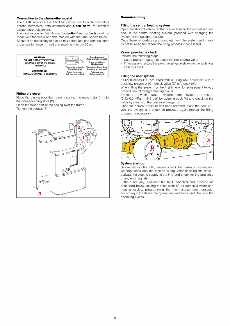
Connection to the chrono-thermostatThe SATK series HIU is fitted for connection to a thermostat orchrono-thermostat, both standard and OpenTherm, for ambienttemperature adjustment.The connection to this device (potential-free contact) must bemade with the two-wire cable marked with the label shown below.Should it be necessary to extend this cable, use one with the samecross-section (max 1 mm2) and maximum length 30 m.
Fitting the coverPlace the casing over the frame, inserting the upper tabs (1) intothe corresponding slots (2).Place the lower part of the casing over the frame. Tighten the screws (3).
3
2
1
Commissioning
Filling the central heating systemOpen the shut-off valves on the connections to the centralised lineand, in the central heating system, proceed with charging thesystem to the design pressure.Once these procedures are complete, vent the system and checkits pressure again (repeat the filling process if necessary)
Vessel pre-charge checkPerform the following steps:- Use a pressure gauge to check the pre-charge value- If necessary, restore the pre-charge value shown in the technicalspecifications.
Filling the user systemSATK30 series HIU are fitted with a filling unit equipped with abackflow preventer (C), check valve (D) and cock (A).When filling the system for the first time or for subsequent top-upprocedures following a heating circuitpressure switch fault, restore the system pressure (0,12–0,2 MPa - 1,2–2 bar) by opening cock (A) and checking thevalue by means of the pressure gauge (B).Once the correct pressure has been reached, close the cock (A),vent the system and check its pressure again (repeat the fillingprocess if necessary)
System start-upBefore starting the HIU, visually check the hydraulic connectionwatertightness and the electric wiring. After finishing the check,activate the electric supply to the HIU and check for the presenceof any error signals.If there are any, eliminate the fault indicated and proceed asdescribed below, setting the set point of the domestic water andheating cycles, programming the thermostat/chrono-thermostataccording to the desired temperatures and times, and checking theoperating cycles.
AB
CD
Raumthermostat(Potenzialfreier Kontakt)
Sonde d’ambiance(Contact sec)
Termostato de ambiente(Contacto sin potencial)
Ruimtesensor(Schoon contact)
WARNING!DO NOT CONNECT EXTERNALVOLTAGE SUPPLY TO THESE
TERMINALS
ATTENZIONE!NON ALIMENTARE IN TENSIONE
Termostato ambiente(Contatto pulito)
Room thermostat(Volt free connection)
7
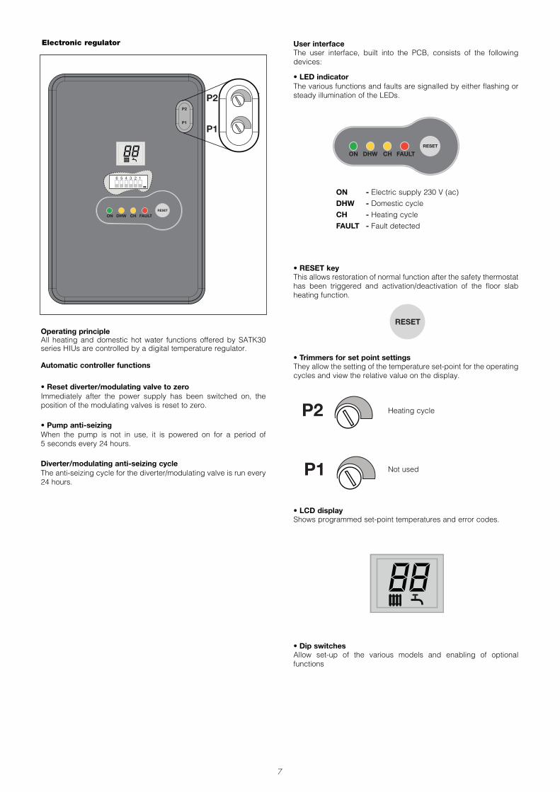
Operating principleAll heating and domestic hot water functions offered by SATK30series HIUs are controlled by a digital temperature regulator.
Automatic controller functions
• Reset diverter/modulating valve to zeroImmediately after the power supply has been switched on, theposition of the modulating valves is reset to zero.
• Pump anti-seizingWhen the pump is not in use, it is powered on for a period of 5 seconds every 24 hours.
Diverter/modulating anti-seizing cycleThe anti-seizing cycle for the diverter/modulating valve is run every24 hours.
• LCD displayShows programmed set-point temperatures and error codes.
88
• Trimmers for set point settingsThey allow the setting of the temperature set-point for the operatingcycles and view the relative value on the display.
• Dip switchesAllow set-up of the various models and enabling of optionalfunctions
User interfaceThe user interface, built into the PCB, consists of the followingdevices:
• LED indicatorThe various functions and faults are signalled by either flashing orsteady illumination of the LEDs.
ON - Electric supply 230 V (ac)DHW - Domestic cycleCH - Heating cycleFAULT - Fault detected
Heating cycle
Electronic regulator
123456
Not used
• RESET keyThis allows restoration of normal function after the safety thermostathas been triggered and activation/deactivation of the floor slabheating function.
8
5
ON
1OFF
48
60
25
48
60
8 seconds
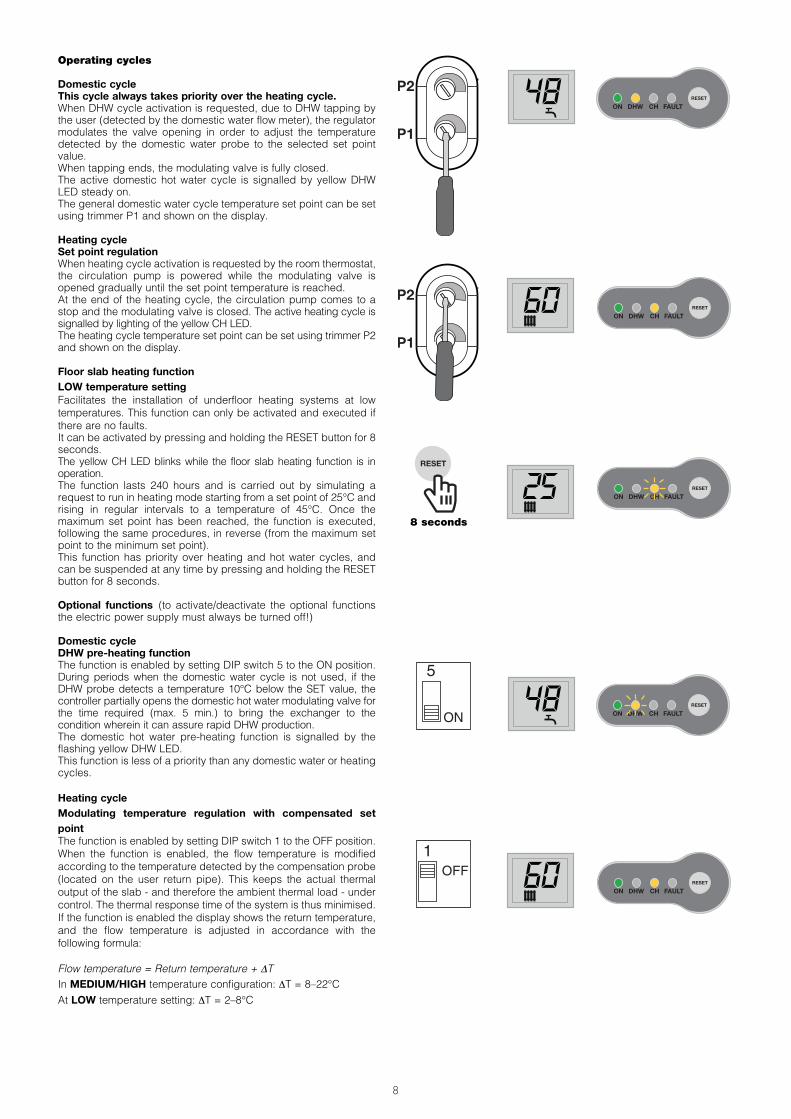
Operating cycles
Domestic cycleThis cycle always takes priority over the heating cycle.When DHW cycle activation is requested, due to DHW tapping bythe user (detected by the domestic water flow meter), the regulatormodulates the valve opening in order to adjust the temperaturedetected by the domestic water probe to the selected set pointvalue.When tapping ends, the modulating valve is fully closed.The active domestic hot water cycle is signalled by yellow DHWLED steady on.The general domestic water cycle temperature set point can be setusing trimmer P1 and shown on the display.
Heating cycle Set point regulationWhen heating cycle activation is requested by the room thermostat,the circulation pump is powered while the modulating valve isopened gradually until the set point temperature is reached.At the end of the heating cycle, the circulation pump comes to astop and the modulating valve is closed. The active heating cycle issignalled by lighting of the yellow CH LED.The heating cycle temperature set point can be set using trimmer P2and shown on the display.
Floor slab heating function LOW temperature settingFacilitates the installation of underfloor heating systems at lowtemperatures. This function can only be activated and executed ifthere are no faults.It can be activated by pressing and holding the RESET button for 8seconds.The yellow CH LED blinks while the floor slab heating function is inoperation.The function lasts 240 hours and is carried out by simulating arequest to run in heating mode starting from a set point of 25°C andrising in regular intervals to a temperature of 45°C. Once themaximum set point has been reached, the function is executed,following the same procedures, in reverse (from the maximum setpoint to the minimum set point).This function has priority over heating and hot water cycles, andcan be suspended at any time by pressing and holding the RESETbutton for 8 seconds.
Optional functions (to activate/deactivate the optional functionsthe electric power supply must always be turned off!)
Domestic cycleDHW pre-heating functionThe function is enabled by setting DIP switch 5 to the ON position.During periods when the domestic water cycle is not used, if theDHW probe detects a temperature 10°C below the SET value, thecontroller partially opens the domestic hot water modulating valve forthe time required (max. 5 min.) to bring the exchanger to thecondition wherein it can assure rapid DHW production.The domestic hot water pre-heating function is signalled by theflashing yellow DHW LED.This function is less of a priority than any domestic water or heatingcycles.
Heating cycleModulating temperature regulation with compensated setpoint The function is enabled by setting DIP switch 1 to the OFF position.When the function is enabled, the flow temperature is modifiedaccording to the temperature detected by the compensation probe(located on the user return pipe). This keeps the actual thermaloutput of the slab - and therefore the ambient thermal load - undercontrol. The thermal response time of the system is thus minimised.If the function is enabled the display shows the return temperature,and the flow temperature is adjusted in accordance with thefollowing formula:
Flow temperature = Return temperature + DTIn MEDIUM/HIGH temperature configuration: DT = 8–22°CAt LOW temperature setting: DT = 2–8°C

9
Safety thermostat cut-out Error code 69
The HIUs configured to support low temperature heatingcontinuously monitor the safety thermostat controlling the flowtemperature.If the safety thermostat is activated during a general cycle, theheating circulation pump immediately comes to a stop and themodulating valve is completely closed. After the user has removed the block imposed by the safetythermostat, operation can only be re-enabled when the modulatingvalves are completely closed again.This means that if a domestic water cycle is in progress, theactivation of the shut-off valve will be postponed until the end of thatdomestic water cycle.
Removing a faultTo restore the operating mode press the manualRESET button.
Safety and alarms
Error codes associated with faults signalled by illumination of theFAULT LED are also shown on the display.
69
Removing a faultNormal operating conditions are restored automatically once thefaulty probe is working properly again (see page 12 - “Temperatureprobe replacement”).
Probe faultIf a temperature probe fails, the associated cycle will be stoppedimmediately and disabled.Any requests to run cycles not associated to the previous one willcontinue to run normally.
Heating probe fault Error code: 5
5
Domestic water probe fault Error code: 6
6Compensation probe fault Error code: 15
Removing a faultRestore the correct switch setting in accordance with theprocedure shown on pages 10-11.
Incorrect switch settingError code 79
79
Removing a faultThe heat interface unit is disabled due to incorrect setting of thedip-switches. Restore the correct switch setting in accordance withthe procedure shown on pages 10-11.
Incorrect switch setting (heat interface unit disabled)Error code 80
80
Heating circuit pressure switch fault Error code 4
The electronic regulator continuously monitors the status of thepressure switch controlling the water pressure in the heating circuit.If the pressure switch is activated, the heating circulation pumpimmediately comes to a stop and the modulating valve is completelyclosed.This fault implies the stoppage of the heating cycle only.Domestic water drawing requests will continue to be served normally.N.B.: A low pre-charge value of the expansion vessel can cause apressure switch fault.
Removing a faultReturn to the operating mode is subordinate to restoration of thecorrect water pressure in the secondary heating circuit (see page6 - “Filling the user system”).
4

10
ON DHW CH FAULT
2
1
0
1
23
4bar
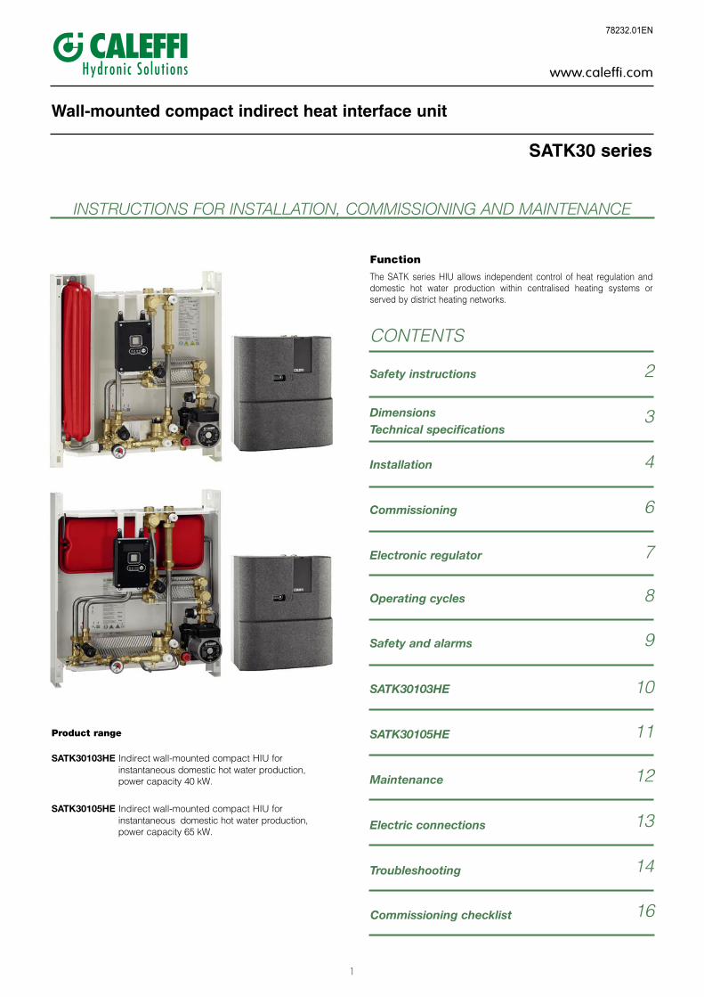
1. Frame2. Expansion vessel3. Electronic regulator4. 2-way modulating valve (primary heating)5. Heating flow temperature probe (secondary)6. DHW heat exchanger7. 2-way modulating valve - DHW 8. Thermal safety thermostat 9. DHW temperature probe10. Secondary heating drain cock 11. Filling unit with backflow preventer 12. Safety relief valve13. Flow temp. compensation return probe14. Primary circuit drain cock15. Pump UPM3 15-70 16. Protective by-pass17. DHW priority flow meter18. Pressure switch19. Secondary heating strainer20. Heating exchanger21. Heat meter spacer template22. Primary circuit strainer/flow probe pocket 23. Primary air vent cock24. Primary circuit shut-off valves
SATK30103HE Indirect HIU with high-efficiency pump. 40 kW DHW.
Functional characteristics
Heating range- LOW temperature setting 25–45°C- MEDIUM/HIGH temperature setting 45–75°C
Set point regulation
DHW production range 42–60°C
Optional functionsDomestic cycle: - DHW pre-heating functionHeating cycle: - modulating temperature regulation
with compensated set pointat LOW temperature setting:
- floor slab heating function
Characteristic components
Factory settingsThe SATK30103HE HIU is factory set to support low temperatureheating (25–45°C), according to the following switch setting.
To modify the factory settings and enable the HIU to supportmedium/high temperature systems (45–75°C), proceed as follows.
1 - cut off the electric power supply to the HIU2 - set switches 2-3 according to the following setting:
3 - disconnect the thermal safety thermostat (see page 13 ref.5) and apply a jumper on the cable (see adjacent diagram)
4 - restore the electric supply.
12356 4
ON
12356
ON
4
Factory set (do not change)
May be changed to activate optional functionsSwitch 1: modulating temperature regulation
with compensated set pointSwitch 2-3: HIGH - LOW temperature settingSwitch 5: DHW pre-heating function
OFF
ON
OFF
ON

11
ON DHW CH FAULT
2
1
0
1
23
4bar
20
11
14
19
18
17
15
16
13
12
23
21
22
3
9
4
7
10
8
6
5
2
1
24
1. Frame2. Expansion vessel3. Electronic regulator4. 2-way modulating valve (primary heating)5. Heating flow temperature probe (secondary)6. DHW heat exchanger7. 2-way modulating valve - DHW 8. Thermal safety thermostat 9. Secondary heating drain cock 10. DHW temperature probe11. Filling unit with backflow preventer 12. Safety relief valve13. Flow temp. compensation return probe14. Primary circuit drain cock15. Pump UPM3 15-7016. Protective by-pass17. Pressure switch18. Heating strainer (secondary)19. DHW priority flow meter20. Heating exchanger21. Heat meter spacer template22. Primary circuit strainer/flow probe pocket 23. Primary air vent cock24. Primary circuit shut-off valves
SATK30105HE Indirect HIU with high efficiency pump. 65 kW DHW.
Characteristic components
Factory settingsThe SATK30105HE HIU is factory set to support low temperatureheating (25–45°C), according to the following switch setting.
To modify the factory settings and enable the HIU to supportmedium/high temperature systems (45–75°C), proceed asfollows.
1 - cut off the electric power supply to the HIU2 - set switches 2-3 according to the following setting:
3 - disconnect the thermal safety thermostat (see page 13 ref. 5) and apply a jumper on the cable (see adjacentdiagram)
4 - restore the electric supply.
Functional characteristics
Heating range- LOW temperature setting 25–45°C- MEDIUM/HIGH temperature setting 45–75°C
Set point regulation
DHW production range 42–60°C
Optional functionsDomestic cycle: - DHW pre-heating functionHeating cycle: - modulating temperature regulation
with compensated set pointat LOW temperature setting:
- floor slab heating function
12356 4
ON
12356
ON
4
Factory set (do not change)OFF
ON
OFF
ON
May be changed to activate optional functionsSwitch 1: modulating temperature regulation
with compensated set pointSwitch 2-3: HIGH - LOW temperature settingSwitch 5: DHW pre-heating function

12
Maintenance
All maintenance procedures should be carried out by an authorisedtechnician.Regular maintenance guarantees better efficiency and helps tosave energy.Before carrying out any maintenance, repair or part replacementwork, proceed as follows:- Cut off the electric supply- Remove the cover- Close the shut-off valves- Empty the HIU using the drain cocks provided.
Heat exchanger replacement- Remove the heat exchanger, loosening the 2 hex socket headscrews fixing it in place (A)
- Replace the heat exchanger and the O-rings.- Tighten the two fixing screws (A).N.B. The pins fixing the heat exchanger are positioned in such a wayas to allow it to be placed only in the correct direction.
Strainer cleaningAll heat interface units have a strainer on the inlet for water from thecentralised system.To clean these strainers, carry out the following maintenanceprocedure:- Unscrew the cap (B)- Remove the strainer mesh and discard any impurities- Refit the strainer mesh- Refit the cap and tighten it.
Temperature probe replacement- Disconnect the probe cable by bending tab (C) slightly and extracting the connector (see page 13, ref. 1-3-7)
- Unscrew the probe- Fit the new probe - Reconnect the connector respecting the only possible way it canbe inserted.
Vessel pre-charge checkFor correct operation of the system periodically check (at leastonce every six months) the vessel pre-charge value.
Replacing the valve obturator- Extract the fixing clip (D) and then the actuator- Position the new actuator (E)- Insert the fixing clip, respecting the correct direction- Reconnect the connector.
Replacing the valve obturator- Disconnect the valve actuator (see previous paragraph) - Extract the obturator by unscrewing the locking nut (F)- Replace the obturator, screw on the locking nut (F) and then fitthe actuator
- Insert the fixing clip, respecting the correct direction- Reconnect the connector.
Replacing the DHW priority flow meter- Disconnect the flow meter cable acting on the connector (seepage 13, ref. 2)
- Extract the flow sensor (G)- Position the new sensor- Reconnect the connector respecting the only possible way it canbe inserted.
Replacing or cleaning the DHW priority flow meter turbineExtract the flow sensor- Unscrew and remove the cartridge (H)- Remove any impurities or change the cartridge if necessary- Screw the cartridge back into place- Refit the flow sensor
When carrying out maintenance on the electrical part, for theconnections follow the diagram on page 13.After concluding maintenance, proceed with the filling andchecking operations described in the chapter “Commissioning”and fit the cover.If you require any information regarding spare parts, please contactCaleffi spa.
AA
C
B
D E
F
G
H

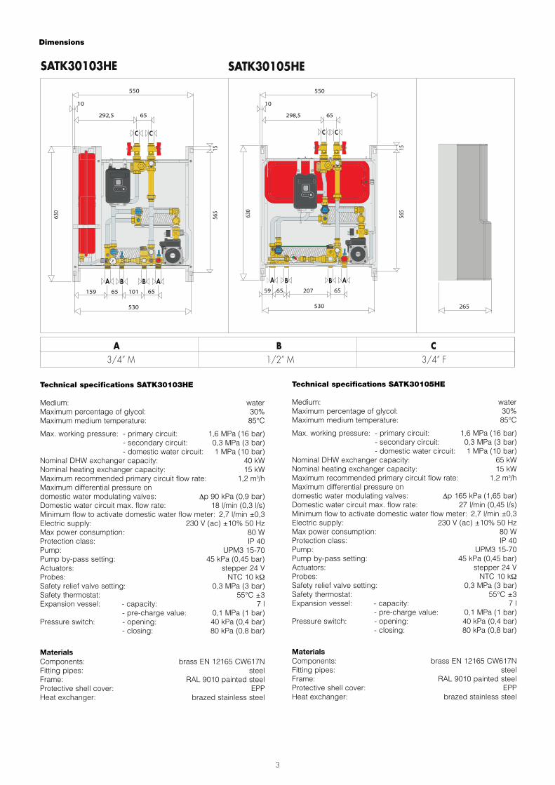
Electric connections
FUSE 5x20
1 2 3 4 65
9
10
13
11
12
6 35 4 2 1
14
7 8
Raumthermostat(Potenzialfreier Kontakt)
Sonde d’ambiance(Contact sec)
Termostato de ambiente(Contacto sin potencial)
Ruimtesensor(Schoon contact)
Termostato ambiente(Contatto pulito)
Room thermostat(Volt free connection)
* Wiring to be made during installation(Room thermostat not supplied)
(potential-free line)
MAX 30 m
1 DHW temperature probe
2 DHW priority flow meter
3 Flow temp. compensation return probe
4 DHW production valve actuator
5 Thermal safety thermostat
6 Pressure switch
7 Heating flow temperature probe
8 Heating valve actuator
9 Earth
10 Pump
11 Electric supply 230V (ac)*
12 Room thermostat*
13 Fuse
14 HIU enabling
13

14
FAULT DESCRIPTION INDICATIONS POSSIBLE CAUSE OF FAULT OPERATIONS TO BE PERFORMED
Water is notheated
DHW LED ON
primary circuit shut-off valves closed open the valvesmodulating valve actuator connector disconnected reconnect actuator connector
modulating valve actuator disconnected from valve body reconnect actuator
modulating valve actuator faulty call qualified personnel to have itreplaced
DHW temperature probe cable inverted with heatingprobe restore correct connection
presence of air in the system vent the system
electronic controller not working call qualified personnel to have itreplaced
valve obturator blocked in closed position call qualified personnel to have itreplaced
centralised system not working/cold contact person in charge of system
FAULT LED ON +error code 6 active
DHW temperature probe disconnected reconnect probe
DHW temperature probe faulty call qualified personnel to have itreplaced
FAULT LED ON +error code 79 active incorrect switch setting restore correct switch setting
FAULT LED ON +error code 80 active incorrect switch setting restore correct switch setting
DHW LED OFFDHW priority flow meter disconnected reconnect flow meter
DHW priority flow meter faulty call qualified personnel to have itreplaced
all LEDs are OFFno electric power supply restore HIU electric supply
protection fuse burnt out call qualified personnel to have itreplaced
The water is hotbut does notreach thedesired
temperature
DHW LED ON
domestic water cycle temperature set point too low increase set point
primary circuit strainer of the HIU clogged call qualified personnel to have itserviced
heat exchanger partly clogged call qualified personnel to have itserviced
modulating valve actuator faulty call qualified personnel to have itreplaced
valve obturator blocked in intermediate position call qualified personnel to have itreplaced
modulating valve actuator connector disconnected reconnect actuator connectorDHW temperature probe cable inverted with heating
probe restore correct connection
excessive demand for DHW decrease demand
electronic controller not working call qualified personnel to have itreplaced
centralised system temperature insufficient contact person in charge of systemprimary circuit flow rate insufficient contact person in charge of system
Hot watertemperature is
too highDHW LED ON
domestic water cycle temperature set point too high decrease set pointDHW temperature probe cable inverted with heating
probe restore correct connection
modulating valve actuator faulty call qualified personnel to have itreplaced
valve obturator blocked in intermediate or open position call qualified personnel to have itreplaced
electronic controller not working call qualified personnel to have itreplaced
primary circuit excessive pressure contact person in charge of system
Hot water flowrate is
insufficientDHW LED ON
HIU strainer clogged call qualified personnel to have itserviced
possible domestic water system shut-off valves partially closed open the valves
centralised domestic circuit cold water flow rateinsufficient
call qualified personnel to have itserviced
Hot water flowrate is zero
DHW LED OFF
possible domestic water system shut-off valves closed open the valves
no cold water in centralised domestic circuit call qualified personnel to have itserviced
HIU strainer completely clogged call qualified personnel to have itserviced
heat exchanger completely blocked call qualified personnel to have itserviced
Troubleshooting
15
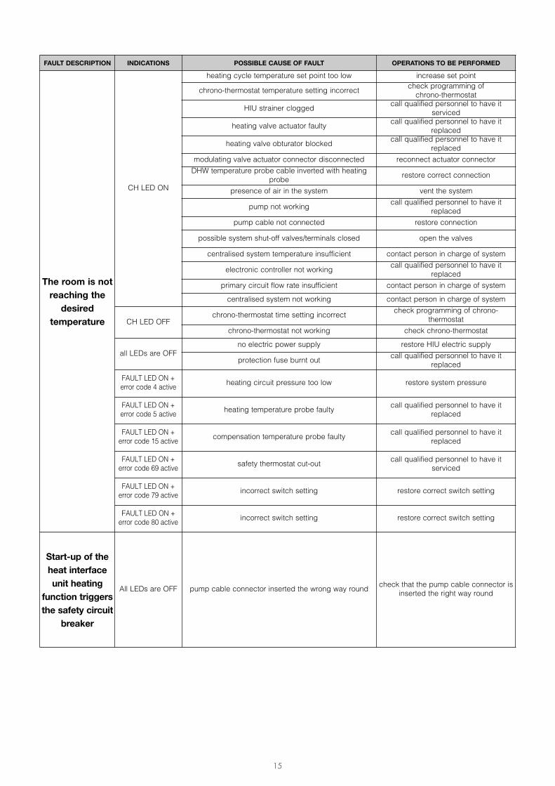
FAULT DESCRIPTION INDICATIONS POSSIBLE CAUSE OF FAULT OPERATIONS TO BE PERFORMED
The room is notreaching thedesired
temperature
CH LED ON
heating cycle temperature set point too low increase set point
chrono-thermostat temperature setting incorrect check programming of chrono-thermostat
HIU strainer clogged call qualified personnel to have itserviced
heating valve actuator faulty call qualified personnel to have itreplaced
heating valve obturator blocked call qualified personnel to have itreplaced
modulating valve actuator connector disconnected reconnect actuator connectorDHW temperature probe cable inverted with heating
probe restore correct connection
presence of air in the system vent the system
pump not working call qualified personnel to have itreplaced
pump cable not connected restore connection
possible system shut-off valves/terminals closed open the valves
centralised system temperature insufficient contact person in charge of system
electronic controller not working call qualified personnel to have itreplaced
primary circuit flow rate insufficient contact person in charge of systemcentralised system not working contact person in charge of system
CH LED OFFchrono-thermostat time setting incorrect check programming of chrono-
thermostatchrono-thermostat not working check chrono-thermostat
all LEDs are OFFno electric power supply restore HIU electric supply
protection fuse burnt out call qualified personnel to have itreplaced
FAULT LED ON +error code 4 active heating circuit pressure too low restore system pressure
FAULT LED ON +error code 5 active heating temperature probe faulty call qualified personnel to have it
replaced
FAULT LED ON +error code 15 active compensation temperature probe faulty call qualified personnel to have it
replaced
FAULT LED ON +error code 69 active safety thermostat cut-out call qualified personnel to have it
serviced
FAULT LED ON +error code 79 active incorrect switch setting restore correct switch setting
FAULT LED ON +error code 80 active incorrect switch setting restore correct switch setting
Start-up of theheat interfaceunit heating
function triggersthe safety circuit
breaker
All LEDs are OFF pump cable connector inserted the wrong way round check that the pump cable connector isinserted the right way round
16
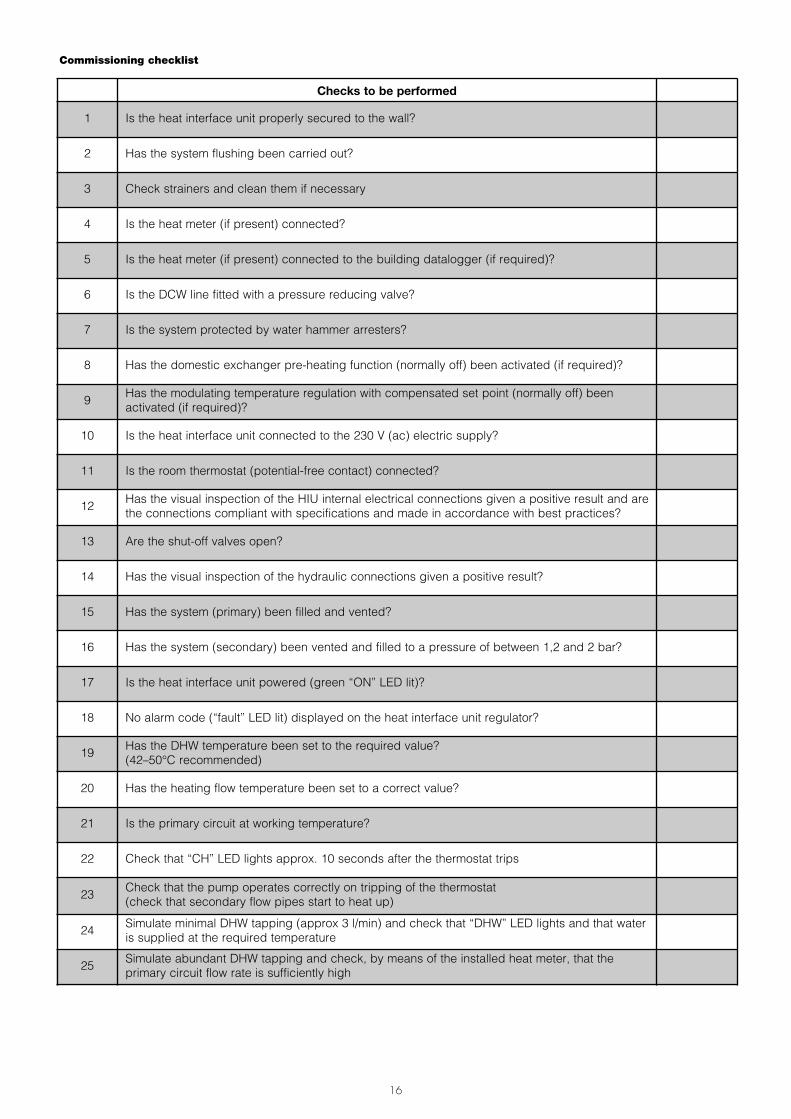
Commissioning checklist
Checks to be performed
1 Is the heat interface unit properly secured to the wall?
2 Has the system flushing been carried out?
3 Check strainers and clean them if necessary
4 Is the heat meter (if present) connected?
5 Is the heat meter (if present) connected to the building datalogger (if required)?
6 Is the DCW line fitted with a pressure reducing valve?
7 Is the system protected by water hammer arresters?
8 Has the domestic exchanger pre-heating function (normally off) been activated (if required)?
9 Has the modulating temperature regulation with compensated set point (normally off) beenactivated (if required)?
10 Is the heat interface unit connected to the 230 V (ac) electric supply?
11 Is the room thermostat (potential-free contact) connected?
12 Has the visual inspection of the HIU internal electrical connections given a positive result and arethe connections compliant with specifications and made in accordance with best practices?
13 Are the shut-off valves open?
14 Has the visual inspection of the hydraulic connections given a positive result?
15 Has the system (primary) been filled and vented?
16 Has the system (secondary) been vented and filled to a pressure of between 1,2 and 2 bar?
17 Is the heat interface unit powered (green “ON” LED lit)?
18 No alarm code (“fault” LED lit) displayed on the heat interface unit regulator?
19 Has the DHW temperature been set to the required value?(42–50°C recommended)
20 Has the heating flow temperature been set to a correct value?
21 Is the primary circuit at working temperature?
22 Check that “CH” LED lights approx. 10 seconds after the thermostat trips
23 Check that the pump operates correctly on tripping of the thermostat(check that secondary flow pipes start to heat up)
24 Simulate minimal DHW tapping (approx 3 l/min) and check that “DHW” LED lights and that wateris supplied at the required temperature
25 Simulate abundant DHW tapping and check, by means of the installed heat meter, that theprimary circuit flow rate is sufficiently high