Walking Tractor-Drawn Planter -...
14
Walking Tractor - Drawn Planter Operating Instructions Phone: +55 42 3522-2789 | +55 42 3522-1819 | +55 42 3523-7926 Rua Prefeito Alfredo Metzler, 480 - CEP 89400-000 - Porto União – SC – Brasil Website: www.knapik.com.br | E-mail: [email protected] [email protected] | [email protected] Single Row Walking Tractor-Drawn Planter for No-Till Planting and Conventional Sowing
Transcript of Walking Tractor-Drawn Planter -...
1
Walking Tractor - Drawn Planter
Operating Instructions
Phone: +55 42 3522-2789 | +55 42 3522-1819 | +55 42 3523-7926
Rua Prefeito Alfredo Metzler, 480 - CEP 89400-000 - Porto União – SC – Brasil
Website: www.knapik.com.br | E-mail: [email protected]
[email protected] | [email protected]
Single Row Walking Tractor-Drawn Planter
for No-Till Planting and Conventional Sowing
2
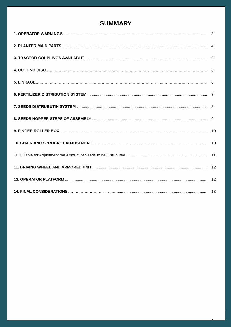
SUMMARY
1. OPERATOR WARNING S..................................................................................................................................... 3
2. PLANTER MAIN PARTS...................................................................................................................................... 4
3. TRACTOR COUPLINGS AVAILABLE ................................................................................................................. 5
4. CUTTING DISC………………………………….…………………………………………….…………………………… 6
5. LINKAGE……………………………………………………………………………………..…………………………….. 6
6. FERTILIZER DISTRIBUTION SYSTEM................................................................................................................ 7
7. SEEDS DISTRUBUTIN SYSTEM …..................................................................................................................... 8
8. SEEDS HOPPER STEPS OF ASSEMBLY .......................................................................................................... 9
9. FINGER ROLLER BOX…………………………………………………………………….…………………………...... 10
10. CHAIN AND SPROCKET ADJUSTMENT…………..………………………………………………………………... 10
10.1. Table for Adjustment the Amount of Seeds to be Distributed ........................................................................... 11
11. DRIVING WHEEL AND ARMORED UNIT .......................................................................................................... 12
12. OPERATOR PLATFORM ................................................................................................................................... 12
14. FINAL CONSIDERATIONS……….…………………….…................................................................................... 13
3
SAFETY AT WORK
Keep in mind that SAFETY requires CONTINUING WARNING,
OBSERVATION and CAUTION during storage and handling, transport and
maintenance of the planter.
PLEASE, READ THE INSTRUCTIONS MANUAL
Before mounting, adjusting or maintenance
procedures, please, consult the instructions
manual.
1. OPERATOR WARNING S
Please, avoid the improper
disposal of waste in the environment,
the planet thank to you
4
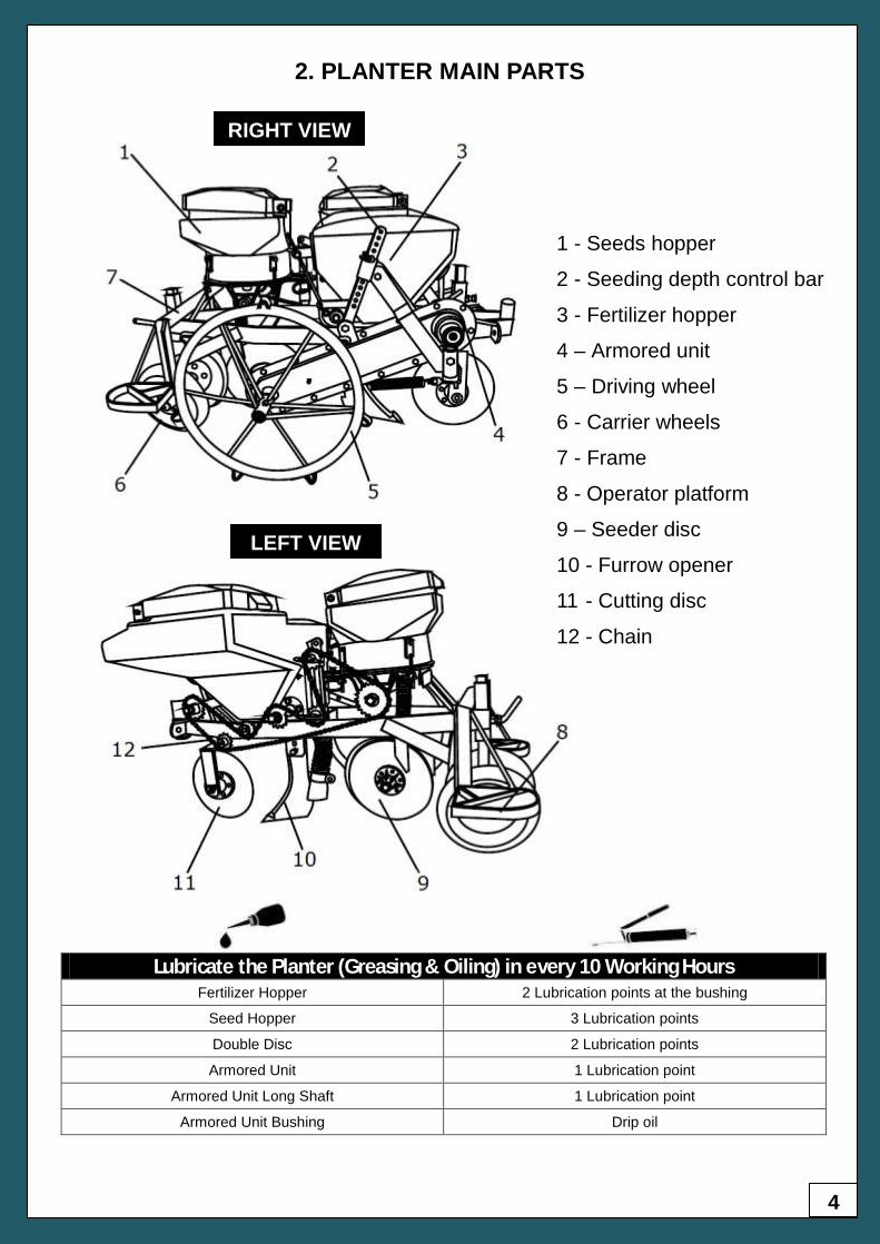
2. PLANTER MAIN PARTS
1 - Seeds hopper
2 - Seeding depth control bar
3 - Fertilizer hopper
4 – Armored unit
5 – Driving wheel
6 - Carrier wheels
7 - Frame
8 - Operator platform
9 – Seeder disc
10 - Furrow opener
11 - Cutting disc
12 - Chain
RIGHT VIEW
LEFT VIEW
Lubricate the Planter (Greasing & Oiling) in every 10 Working Hours
Fertilizer Hopper 2 Lubrication points at the bushing
Seed Hopper 3 Lubrication points
Double Disc 2 Lubrication points
Armored Unit 1 Lubrication point
Armored Unit Long Shaft 1 Lubrication point
Armored Unit Bushing Drip oil
5
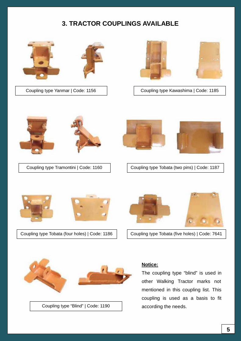
3. TRACTOR COUPLINGS AVAILABLE
Coupling type Yanmar | Code: 1156 Coupling type Kawashima | Code: 1185
Coupling type Tramontini | Code: 1160
Coupling type Tobata (two pins) | Code: 1187
Coupling type Tobata (four holes) | Code: 1186
Coupling type Tobata (five holes) | Code: 7641
Coupling type “Blind” | Code: 1190
Notice:
The coupling type “blind” is used in
other Walking Tractor marks not
mentioned in this coupling list. This
coupling is used as a basis to fit
according the needs.
6
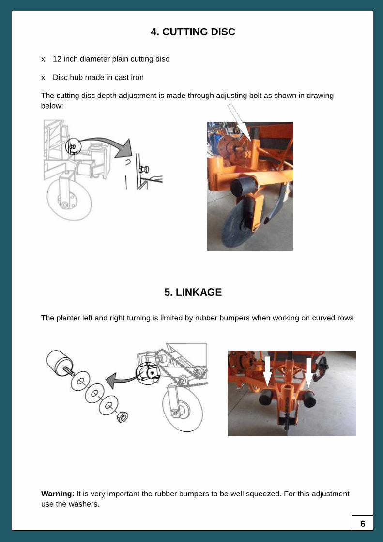
x 12 inch diameter plain cutting disc
x Disc hub made in cast iron
4. CUTTING DISC
The planter left and right turning is limited by rubber bumpers when working on curved rows
The cutting disc depth adjustment is made through adjusting bolt as shown in drawing
below:
5. LINKAGE
Warning: It is very important the rubber bumpers to be well squeezed. For this adjustment
use the washers.
7
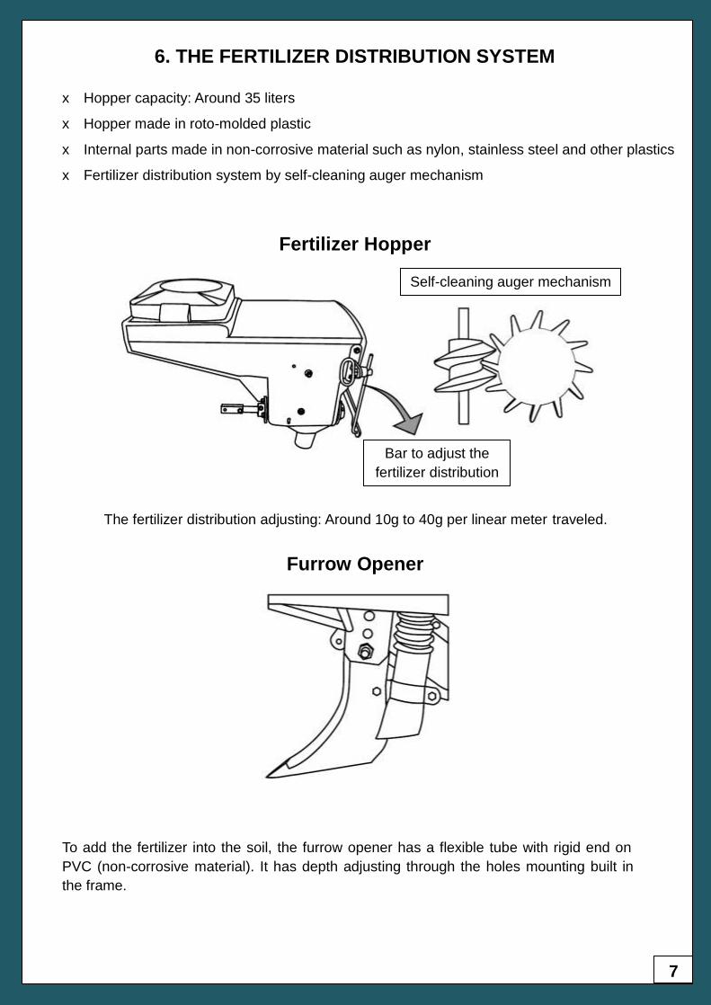
The fertilizer distribution adjusting: Around 10g to 40g per linear meter traveled.
To add the fertilizer into the soil, the furrow opener has a flexible tube with rigid end on
PVC (non-corrosive material). It has depth adjusting through the holes mounting built in
the frame.
6. THE FERTILIZER DISTRIBUTION SYSTEM
x Hopper capacity: Around 35 liters
x Hopper made in roto-molded plastic
x Internal parts made in non-corrosive material such as nylon, stainless steel and other plastics
x Fertilizer distribution system by self-cleaning auger mechanism
Fertilizer Hopper
Bar to adjust the
fertilizer distribution
Self-cleaning auger mechanism
Furrow Opener
8
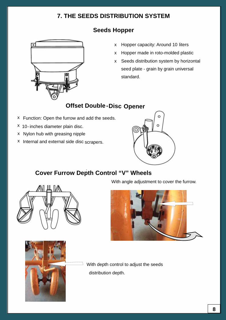
7. THE SEEDS DISTRIBUTION SYSTEM
x Hopper capacity: Around 10 liters
x Hopper made in roto-molded plastic
x Seeds distribution system by horizontal
seed plate - grain by grain universal
standard.
Offset Double -Disc
Opener
x
Function: Open the furrow and add the seeds.
x
10- inches diameter plain disc.
x
Nylon hub with greasing nipple
.
x
Internal and external side disc scrapers.
With angle adjustment to cover the furrow.
With depth control to adjust the seeds
distribution depth.
Cover Furrow Depth Control “V” Wheels
Seeds Hopper
9
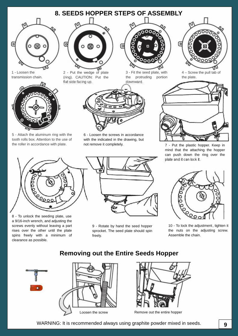
1 - Loosen the
transmission chain.
2 - Put the wedge of plate
(ring). CAUTION: Put the
flat side facing up.
3 - Fit the seed plate, with
the protruding portion
downward.
4 – Screw the pull tab of
the plate.
5 - Attach the aluminum ring with the
tooth rolls box. Attention to the use of
the roller in accordance with plate.
6 - Loosen the screws in accordance
with the indicated in the drawing, but
not remove it completely. 7 - Put the plastic hopper. Keep in
mind that the attaching the hopper
can push down the ring over the
plate and it can lock it.
8 - To unlock the seeding plate, use
a 9/16-inch wrench, and adjusting the
screws evenly without leaving a part
rises over the other until the plate
spins freely with a minimum of
clearance as possible.
9 - Rotate by hand the seed hopper
sprocket. The seed plate should spin
freely.
10 - To lock the adjustment , tighten it
the nuts on the adjusting screw.
Assemble the chain.
Removing out the Entire Seeds Hopper
Loosen the screw Remove out the entire hopper
WARNING: It is recommended always using graphite powder mixed in seeds.
8. SEEDS HOPPER STEPS OF ASSEMBLY
10
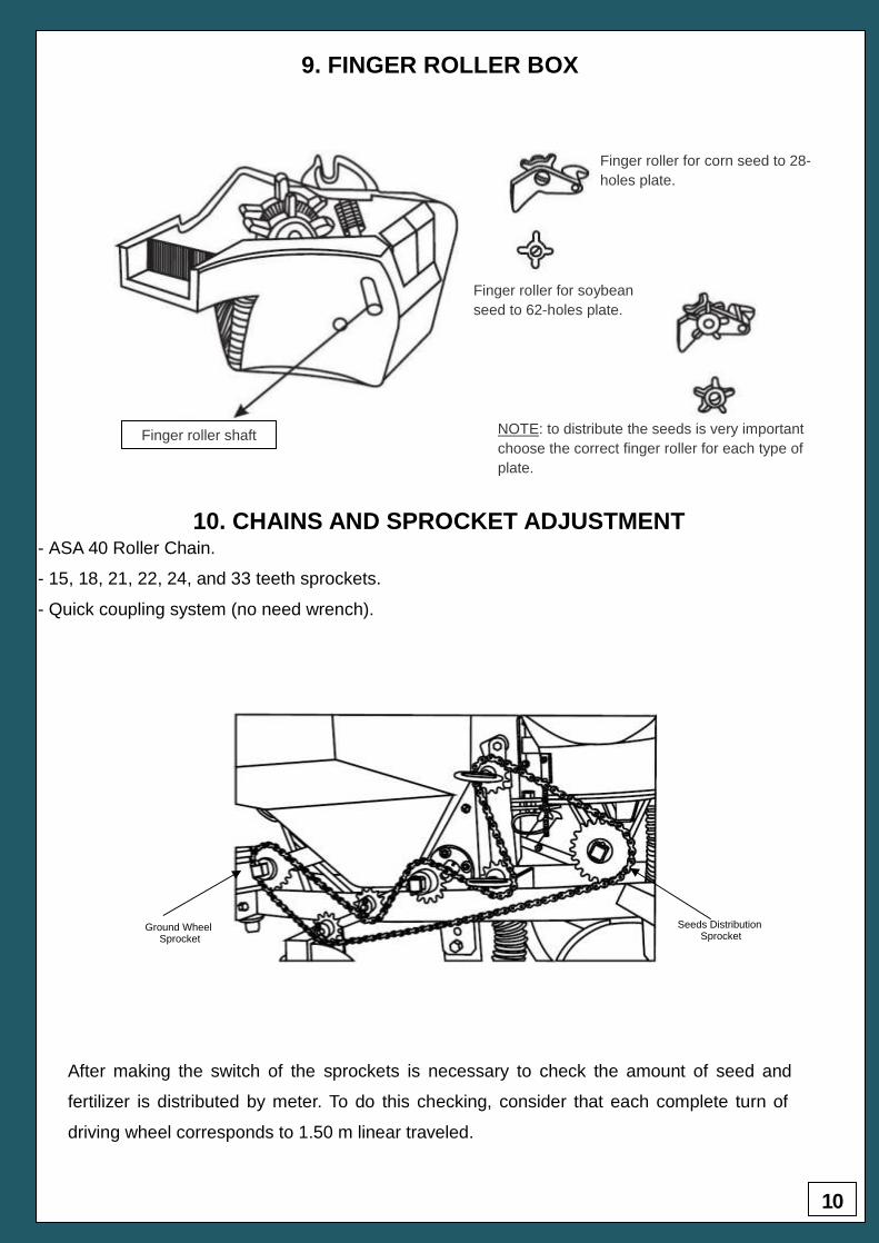
9. FINGER ROLLER BOX
Finger roller shaft
Finger roller for corn seed to 28-
holes plate.
Finger roller for soybean
seed to 62-holes plate.
NOTE: to distribute the seeds is very important
choose the correct finger roller for each type of
plate.
10. CHAINS AND SPROCKET ADJUSTMENT
- ASA 40 Roller Chain.
- 15, 18, 21, 22, 24, and 33 teeth sprockets.
- Quick coupling system (no need wrench).
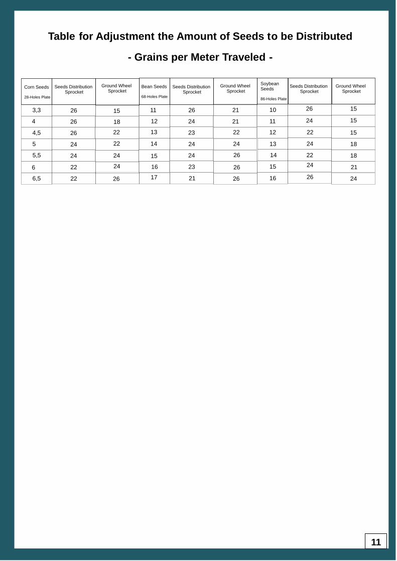
After making the switch of the sprockets is necessary to check the amount of seed and
fertilizer is distributed by meter. To do this checking, consider that each complete turn of
driving wheel corresponds to 1.50 m linear traveled.
Seeds Distribution Sprocket
Ground Wheel Sprocket
11
Table for Adjustment the Amount of Seeds to be Distributed
- Grains per Meter Traveled -
3,3
264
4,5
5
5,5
6
6,5
26
26
24
24
22
22
15
18
22
22
24
24
26
11
12
13
14
15
16
17
26
24
23
24
24
23
21
21
21
22
24
26
26
26
10
11
12
13
14
15
16
26
24
22
24
22
24
26
15
15
15
18
18
21
24
Corn Seeds
28-Holes Plate
Bean Seeds
68-Holes Plate
Soybean Seeds
86-Holes Plate
Seeds Distribution Sprocket
Seeds Distribution Sprocket
Seeds Distribution Sprocket
Ground Wheel Sprocket
Ground Wheel Sprocket
Ground Wheel Sprocket
12
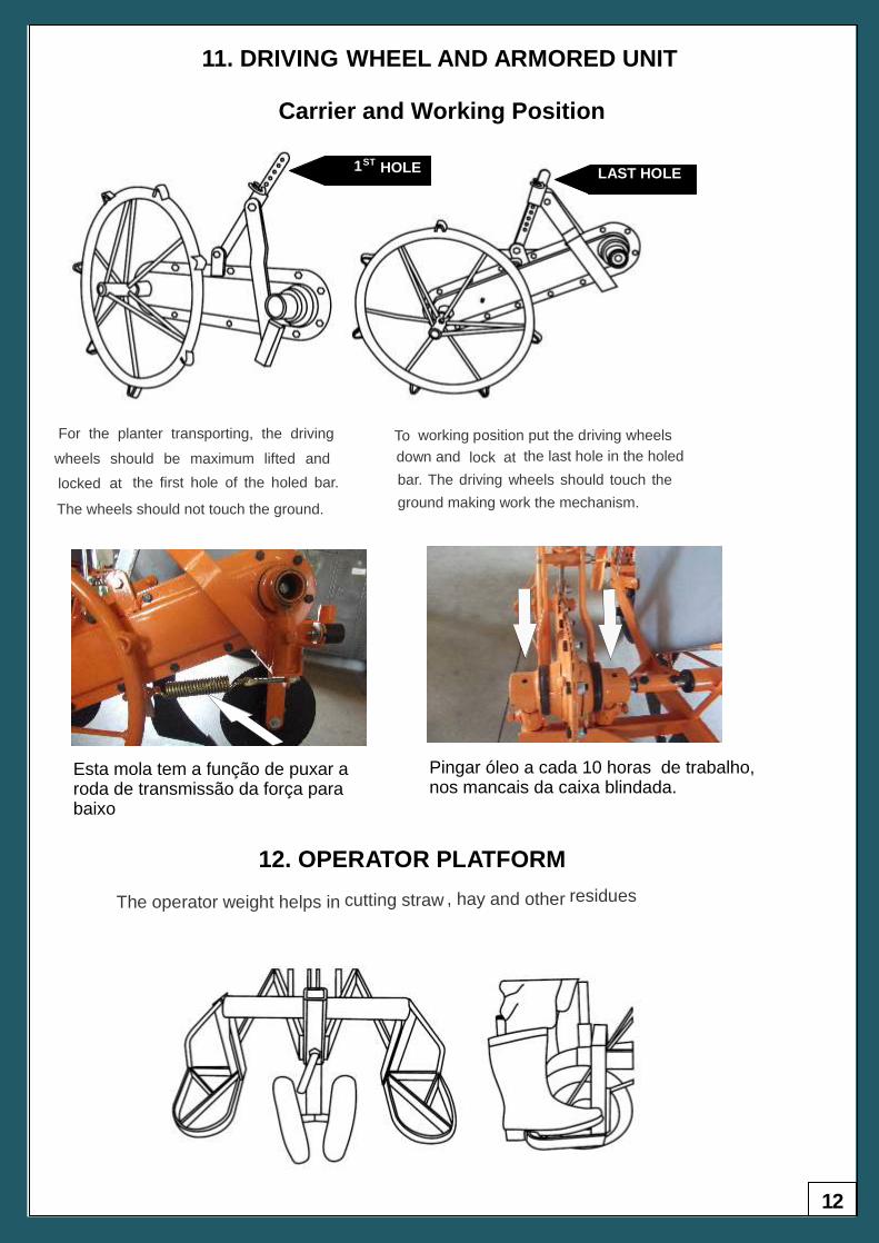
11. DRIVING WHEEL AND ARMORED UNIT
Carrier and Working Position
For the planter transporting, the driving
wheels should be maximum lifted and
locked at
the first hole of the holed bar.
The wheels should not touch the ground.
To
working position put the driving wheels
down and lock at
the last hole in the holed
bar. The driving wheels should touch the
ground making work the mechanism.
LAST HOLE
1ST
HOLE
12. OPERATOR PLATFORM
The operator weight helps in
cutting straw , hay and other
residues
.
Esta mola tem a função de puxar a roda de transmissão da força para baixo
Pingar óleo a cada 10 horas de trabalho,nos mancais da caixa blindada.

13
13. FINAL CONSIDERATIONS
In this manual, some images and drawings are not appearing the safety devices (how
to cover, guards, etc.) to be able to show clearly and give more detailed instructions.
But do not forget; never operate the machine without these devices.
Indústria Mecânica Knapik Ltda reserves the right to improve and/or modify the
technical characteristics of its products without prior notice and without obligation to
extend the improvements and modifications to the machines already sold.
14
Indústr
ia M
ecânic
a K
napik
Ltd
a
SEPTEMBER 2012 A empresa se reserva o direito de proceder alterações de seus produtos sem aviso prévio. La empresa se reserva el derecho de proceder alteraciones de sus productos sin aviso previo. The company reserves the right to modify the products without prior notice.
INDÚSTRIA MECÂNICA KNAPIK LTDA
Rua Prefeito Alfredo Metzler, 480 - Bairro Santa Rosa
89400-000 Porto União – SC – Brasil
Tels: +55 (42) 3522-2789 | +55 (42) 3522-1819 | +55 (42) 3523-7926
Web: www.knapik.com.br
Email: [email protected]