WALK-IN VAN CHASSIS - fccccommercial.com · tained as indicated in the Walk-In Van Chassis...
177
Operator’s Manual STI-471-6 A24-01451-000 WALK-IN VAN CHASSIS
Transcript of WALK-IN VAN CHASSIS - fccccommercial.com · tained as indicated in the Walk-In Van Chassis...

Operator’s Manual
STI-471-6
A24-01451-000
WALK-IN VANCHASSIS

IntroductionThis manual provides information needed to operateand understand the chassis and its components.More detailed information is contained in the Owner’sWarranty Information for North America booklet, andin the vehicle’s workshop and maintenance manuals.
Freightliner chassis are equipped with various chas-sis and cab components. Not all of the informationcontained in this manual applies to every chassis. Ifparts on your chassis differ from those shown, theymay have been installed by the body builder.
The safety or performance of your vehicle could beadversely affected by the installation of nonstandardcomponents. Note the limitations and specificationsprovided in the vehicle and chassis manuals, andconsult your selling dealer before making any altera-tions to the vehicle or chassis.
For your reference, keep this manual in the vehicleat all times.
IMPORTANT: Descriptions and specifications inthis manual were in effect at the time of printing.Freightliner Custom Chassis Corporation re-serves the right to discontinue models and tochange specifications or design at any timewithout notice and without incurring obligation.Descriptions and specifications contained in thispublication provide no warranty, expressed orimplied, and are subject to revisions and edi-tions without notice.
Environmental Concerns andRecommendationsWhenever you see instructions in this manual to dis-card materials, you should first attempt to reclaimand recycle them. To preserve our environment, fol-low appropriate environmental rules and regulationswhen disposing of materials.
Event Data RecorderThis vehicle is equipped with one or more devicesthat record specific vehicle data. The type andamount of data recorded varies depending on howthe vehicle is equipped (such as the brand of engine,if an air bag is installed, or if the vehicle features acollision avoidance system, etc.).
This vehicle is equipped with an event data recorder(EDR). The main purpose of an EDR is to recorddata in certain crash or near-crash situations, suchas air bag deployment or hitting a road obstacle, thatwill assist in understanding how a vehicle’s systemsperformed. The EDR is designed to record data re-lated to vehicle dynamics and safety systems for ap-proximately 60 seconds. This data can help providea better understanding of the circumstances in whichcrashes and injuries occur. Data recorded includesthe following items:
• how various systems in the vehicle were oper-ating
• engine system information
• how far (if at all) the driver was depressing theaccelerator
• if the driver was depressing the brake pedal
• how fast the vehicle was traveling
NOTE: Data is not recorded by the EDR undernormal driving conditions. Personal data suchas name, gender, age, and crash location arenot recorded. However, other parties such aslaw enforcement could combine the EDR datawith the type of personally identifying data rou-tinely acquired during a crash investigation.
To read data recorded by an EDR, special equipmentis required, and access to the vehicle or the EDR isneeded. In addition to the vehicle manufacturer, otherparties that have the special equipment, such as lawenforcement, can read the information if they haveaccess to the vehicle or the EDR.
Emissions and Fuel EfficiencyComplianceThis vehicle must be regularly inspected and main-tained as indicated in the Walk-In Van Chassis Main-tenance Manual, and in the Pre- and Post-Trip In-spections and Maintenance chapter in this manual, inorder to continue satisfactory performance and en-sure coverage of the vehicle under the manufactur-er’s warranty. Many maintenance procedures ensurethat the vehicle and engine continue to comply withapplicable emissions standards. Maintenance proce-dures, using components engineered to comply withgreenhouse gas emissions and fuel efficiency regula-tions, may be performed by an authorized Daimler
Foreword
STI-471-6 (11/15)A24-01451-000
Printed in U.S.A.

Trucks North America dealer, an independent outlet,or the vehicle owner or operator.
The vehicle owner is responsible for determining thesuitability of replacement components to maintaincompliance with federal and local jurisdictional regu-lations. Components including, but not limited to, low-rolling resistance tires are specifically designed andmanufactured to exacting standards for regulatoryfuel efficiency and greenhouse gas emissions compli-ance. It is important that these components are al-ways replaced with components that meet or exceedthe performance of the originally installed compo-nents.
Customer Assistance CenterHaving trouble finding service? Call the CustomerAssistance Center at 1-800-385-4357 or 1-800-FTL-HELP. Call night or day, weekdays or weekends, fordealer referral, vehicle information, breakdown coor-dination, or Fleetpack assistance. Our people areknowledgeable, professional, and committed to fol-lowing through to help you keep your vehicle moving.Please visit www.Daimler-TrucksNorthAmerica.com.
Reporting Safety DefectsIf you believe that your vehicle has a defect whichcould cause a crash or could cause injury ordeath, you should immediately inform the NationalHighway Traffic Safety Administration (NHTSA) inaddition to notifying Freightliner Custom ChassisCorporation.
If the NHTSA receives similar complaints, it mayopen an investigation, and if it finds that a safetydefect exists in a group of vehicles, it may order arecall and remedy campaign. However, NHTSAcannot become involved in individual problemsbetween you, your dealer, or Freightliner CustomChassis Corporation.
To contact NHTSA, you may call the VehicleSafety Hotline toll-free at 1-888-327-4236 (TTY:1-800-424-9153); go to www.safercar.gov; orwrite to: Administrator, NHTSA, 1200 New JerseyAvenue, SE, Washington, DC 20590. You can also
obtain other information about motor vehicle safetyfrom www.safercar.gov.
Canadian customers who wish to report a safety-related defect to Transport Canada, Defect Investi-gations and Recalls, may telephone the toll-freehotline 1-800-333-0510, or contact TransportCanada by mail at: Transport Canada, ASFAD,Place de Ville Tower C, 330 Sparks Street, Ot-tawa, Ontario, Canada K1A 0N5.
For additional road safety information, please visitthe Road Safety website at: www.tc.gc.ca/roadsafety.
© 1997–2016 Daimler Trucks North America LLC. All rights reserved. Daimler Trucks North America LLC is a Daimler
company.
No part of this publication, in whole or part, may be translated, reproduced, stored in a retrieval system, or transmittedin any form by any means, electronic, mechanical, photocopying, recording, or otherwise, without the prior written per-mission of Daimler Trucks North America LLC. For additional information, please contact Daimler Trucks NorthAmerica LLC, Service Systems and Documentation, P.O. Box 3849, Portland OR 97208-3849 U.S.A. or refer towww.Daimler-TrucksNorthAmerica.comand www.FreightlinerTrucks.com.
Foreword

ContentsChapter Page
Introduction, Environmental Concerns and Recommendations,Event Data Recorder, Emissions and Fuel Efficiency Compliance,Customer Assistance Center, Reporting Safety Defects . . . . . . . . . . . . . . . . . . . . Foreword
1 Vehicle Identification . . . . . . . . . . . . . . . . . . . . . . . . . . . . . . . . . . . . . . . . . . . . . . . . . . . . . . 1.12 Instruments . . . . . . . . . . . . . . . . . . . . . . . . . . . . . . . . . . . . . . . . . . . . . . . . . . . . . . . . . . . . . 2.13 Controls . . . . . . . . . . . . . . . . . . . . . . . . . . . . . . . . . . . . . . . . . . . . . . . . . . . . . . . . . . . . . . . . 3.14 Engines . . . . . . . . . . . . . . . . . . . . . . . . . . . . . . . . . . . . . . . . . . . . . . . . . . . . . . . . . . . . . . . . 4.15 Transmissions . . . . . . . . . . . . . . . . . . . . . . . . . . . . . . . . . . . . . . . . . . . . . . . . . . . . . . . . . . . 5.16 Steering System . . . . . . . . . . . . . . . . . . . . . . . . . . . . . . . . . . . . . . . . . . . . . . . . . . . . . . . . . 6.17 Hydraulic and Air Brake Systems . . . . . . . . . . . . . . . . . . . . . . . . . . . . . . . . . . . . . . . . . . . 7.18 Compressed Natural Gas Fuel System . . . . . . . . . . . . . . . . . . . . . . . . . . . . . . . . . . . . . . . 8.19 Hybrid Electric Vehicle . . . . . . . . . . . . . . . . . . . . . . . . . . . . . . . . . . . . . . . . . . . . . . . . . . . . 9.1
10 Pre- and Post-Trip Checklists . . . . . . . . . . . . . . . . . . . . . . . . . . . . . . . . . . . . . . . . . . . . . 10.111 Pre- and Post-Trip Inspections and Maintenance . . . . . . . . . . . . . . . . . . . . . . . . . . . . . . 11.112 Cleaning and Care . . . . . . . . . . . . . . . . . . . . . . . . . . . . . . . . . . . . . . . . . . . . . . . . . . . . . . 12.113 In an Emergency . . . . . . . . . . . . . . . . . . . . . . . . . . . . . . . . . . . . . . . . . . . . . . . . . . . . . . . 13.114 Towing . . . . . . . . . . . . . . . . . . . . . . . . . . . . . . . . . . . . . . . . . . . . . . . . . . . . . . . . . . . . . . . . 14.115 GM Gasoline Engine . . . . . . . . . . . . . . . . . . . . . . . . . . . . . . . . . . . . . . . . . . . . . . . . . . . . 15.116 Hydraulic Hybrid . . . . . . . . . . . . . . . . . . . . . . . . . . . . . . . . . . . . . . . . . . . . . . . . . . . . . . . . 16.117 Propane Fuel System . . . . . . . . . . . . . . . . . . . . . . . . . . . . . . . . . . . . . . . . . . . . . . . . . . . . 17.118 Specifications . . . . . . . . . . . . . . . . . . . . . . . . . . . . . . . . . . . . . . . . . . . . . . . . . . . . . . . . . . 18.1
Index . . . . . . . . . . . . . . . . . . . . . . . . . . . . . . . . . . . . . . . . . . . . . . . . . . . . . . . . . . . . . . . . . . I.1
1
Vehicle IdentificationComponent Information Label . . . . . . . . . . . . . . . . . . . . . . . . . . . . . . . . . . . . . . . . . . . . . . . . . . . . . . . 1.1Vehicle Identification Number (VIN) . . . . . . . . . . . . . . . . . . . . . . . . . . . . . . . . . . . . . . . . . . . . . . . . . . 1.1Emissions Labels . . . . . . . . . . . . . . . . . . . . . . . . . . . . . . . . . . . . . . . . . . . . . . . . . . . . . . . . . . . . . . . . . 1.1

Component Information LabelNOTE: Labels shown in this chapter are ex-amples only. Actual specifications may vary fromvehicle to vehicle.
The component information label lists the manufac-turer, month and year of manufacture, vehicle identifi-cation number (VIN), gross vehicle weight rating(GVWR), front and rear gross axle weight ratings(GAWR), and tire and wheel information. It also indi-cates if the vehicle has been certified as compliantwith Federal Motor Vehicle Safety Standard(FMVSS). See Fig. 1.1.
The tire and rim portion of the component informationlabel certifies suitable tire and rim combinations thatcan be installed on the vehicle for the given grossaxle weight rating. Tires and rims installed on thevehicle at the time of manufacture may have a higherload capacity than that certified by the tire and rimlabel. If the tires and rims currently on the vehiclehave a lower load capacity than that shown on the
tire and rim label, then the tires and rims determinethe load limitations on each of the axles.
Incomplete vehicles intended for service in the U.S.have an incomplete vehicle certification label at-tached by the final-stage manufacturer. This label willbe attached to the incomplete vehicle document in-cluded with the vehicle, and certifies that the vehicleconforms to all applicable FMVSS regulations in ef-fect on the date of completion.
Vehicle Identification Number(VIN)The chassis vehicle identification number is perma-nently attached to the chassis in the engine compart-ment (depending on vehicle options, usually on themetal panel where the steering driveline enters theengine compartment). See Fig. 1.2. The last six dig-its are the chassis serial number. The chassis num-ber is stamped on the left frame rail, over the frontaxle. A VIN label is also mounted by the bodybuilder. Mounting locations vary, to include the glovebox. See Fig. 1.3.
NOTE: Always include the chassis serial num-ber (last six digits of the VIN) when communi-cating with Daimler Trucks North America.
Emissions LabelsAftertreatment System IndicatorsLabelEngines and vehicles manufactured after December31, 2006 and domiciled in the U.S. or Canada arerequired to meet all EPA regulations effective as ofthe vehicle build date, and are equipped with anemission aftertreatment system (ATS). Vehicles do-miciled outside of the U.S. and Canada may not
09/11/2002 f080123
Fig. 1.1, Component Information Label
GAFFNEY, SOUTH CAROLINA, USA4UZA4FVC0TC748531
f080061a04/18/2005
Fig. 1.2, Vehicle Identification Number (VIN) Label
Vehicle Identification
1.1

have aftertreatment equipment, depending upon localstatutory emissions guidelines. See Table 1.1.
A reference label included with the driver’s documen-tation package contains important warning indicatorsin the instrument cluster that pertain to the ATS. SeeFig. 1.4.
It is a violation of U.S. federal law to alter exhaustplumbing, ATS, or other components in any way thatwould bring the engine/vehicle out of compliance withcertification requirements [Ref: 42 U.S.C. S7522(a)(3)]. It is the owner’s responsibility to maintain thevehicle so that it conforms to EPA regulations.
Vehicle Emission Control InformationLabelModel year 2013 and later vehicles meet additionalrequirements as specified by federal greenhouse gasand fuel efficiency regulations (GHG14). Model year2017 and later vehicles meet similar requirements asspecified by GHG17 requirements. These vehiclesare equipped with components that increase fuel effi-ciency and reduce GHG emissions. Componentsmay include, but are not limited to, low-rolling resis-tance tires.
Applicable Emissions System Based on Build Date and EPA RegulationsBuild Date Regulation: Emissions Components
January 1, 2007–December 31,2009
EPA07 (reduce nitrogen oxides (NOx) emissions to 1.1 g/bhp-hr, and reduceparticulate matter emissions to 0.01 g/bhp-hr): Aftertreatment device (ATD) containinga diesel particulate filter that traps soot and ash.*
January 1, 2010–December 31,2012
EPA10 (reduce NOx emissions to 0.2 g/bhp-hr): EPA07-type ATD, with additionalselective catalyst reduction (SCR) technology that utilizes diesel exhaust fluid (DEF)to convert NOx to nitrogen and water vapor.
From March 5, 2012–December31, 2015
GHG14: Aerodynamic and fuel efficiency components including, but not limited to,tires, cab/sleeper side extenders, chassis fairings, bumper, hood, vehicle speedlimiters, and idle reduction timers specifically designed to meet regulatory fuelefficiency and greenhouse gas emissions standards.
12/04/2001 f080122
Fig. 1.3, Vehicle Identification Number Label, Typical
Vehicle Identification
1.2

Applicable Emissions System Based on Build Date and EPA RegulationsBuild Date Regulation: Emissions Components
From January 1, 2016GHG17: GHG14 components plus OBD16 instrumentation and sensor upgrades, andcomponent technology that meets NHTSA and EPA 2017 fuel efficiency andgreenhouse gas emission standards (GHG17) requirements.
* Cummins, Detroit, and Mercedes-Benz ATD’s are also equipped with a diesel oxidation catalyst to break down pollutants.
Table 1.1, Applicable Emissions System Based on Build Date and EPA Regulations
A Vehicle Emission Control Information Label indi-cates compliance with GHG14 regulations. SeeFig. 1.5. It is the owner’s responsibility to maintainthe vehicle so that it conforms to EPA and NHTSAregulations.
Certified Clean Idle LabelThe California Air Resources Board (CARB) requiresmodel year 2008 and newer heavy-duty diesel en-gines to be equipped with a non-programmable en-gine shutdown system that automatically shuts downthe engine after five minutes of idling in order to limitemissions of particulate matter and NOx.
Certified vehicles are equipped with a label placednear the bottom edge of the driver-side door. SeeFig. 1.6.
f080156
EXHAUST AFTERTREATMENT SYSTEM INFORMATION
Switch.
Level 1 Level 3Level 2 Level 4Filter RegenerationRecommended.
Filter is reaching
Bring vehicle tohighway speeds to
Filter Regeneration
Filter is nowreaching maximumcapacity.
To avoid enginederate, bring vehicle
Parked RegenerationRequired − EngineDerate
Filter has reachedmaximum capacity.
Vehicle must beparked, and a Parked
Service Regeneration Required.Engine Derate To Idle Only.
Filter has exceeded maximumcapacity.
Vehicle must be parked, and aService Regeneration must be
(Solid) (Flashing) (Flashing)
CHECKINDICATORLAMP(S)
Indicator LampMessage(s)
Diesel ParticulateFilter Condition
Required Action
capacity.
STOP
allow for an AutomaticRegeneration orperform a Parked
to highway speedsto allow for anAutomaticRegeneration, orperform a ParkedRegeneration assoon as possible.
Regeneration mustbe performed.Engine will beginderate.
performed. Check engineoperator’s manual for details.Engine will shut down.
For a driver performed Parked Regeneration, vehicle must be equipped with a dash mounted Regeneration Switch.
02/20/2009
WARNING
HEST (High ExhaustSystem Temperature)
Exhaust componentsand exhaust gas are athigh temperature. Whenstationary, keep awayfrom people andflammable materials orvapors.
A regeneration is inprogress.
Flashing
Solid
Regeneration.
Necessary
Fig. 1.4, ATS Indicators
03/02/2012 f080183
Fig. 1.5, Vehicle Emission Control Information Label
Vehicle Identification
1.3

CERTIFIEDCLEAN IDLE
02/20/2012 f080179
Fig. 1.6, CARB Clean Idle Label
Vehicle Identification
1.4

2
InstrumentsAmetek Instrument Panel . . . . . . . . . . . . . . . . . . . . . . . . . . . . . . . . . . . . . . . . . . . . . . . . . . . . . . . . . . . 2.1Warning and Indicator Lights . . . . . . . . . . . . . . . . . . . . . . . . . . . . . . . . . . . . . . . . . . . . . . . . . . . . . . . . 2.9Speedometer and Tachometer . . . . . . . . . . . . . . . . . . . . . . . . . . . . . . . . . . . . . . . . . . . . . . . . . . . . . . 2.16Standard Instruments . . . . . . . . . . . . . . . . . . . . . . . . . . . . . . . . . . . . . . . . . . . . . . . . . . . . . . . . . . . . . 2.17Optional Instruments . . . . . . . . . . . . . . . . . . . . . . . . . . . . . . . . . . . . . . . . . . . . . . . . . . . . . . . . . . . . . 2.19

Ametek Instrument PanelThe following information describes a typical instru-ment panel manufactured by Ametek. Figure 2.1 andFig. 2.2 show instrument panels for vehicles that arecompliant with EPA10 and newer regulations, forboth diesel and hybrid-electric vehicles (HEV). Fig-ure 2.3 and Fig. 2.4 show instrument panels for ve-hicles that are EPA07-compliant for both diesel andHEV vehicles.
NOTE: These instrument panels are shown witha standard U.S. speedometer, which showsmiles per hour (mph) more prominently than ki-lometers per hour (km/h).
Message Display CenterThe message display is a graphical, backlit, liquidcrystal display (LCD) that relays information to thevehicle operator. The messages displayed include:
• Odometer
• Trip Odometer 1/Trip Odometer 2
• Chassis Battery Voltage
• Instantaneous Fuel Rate
• Average Fuel Rate
• Gear Attained Status
• Transmission Temperature
• Hour Meter
• Boost Pressure
• Engine Oil Pressure
• Coolant Temperature
• Fuel Level
• Percent Engine Load
• Engine RPM
During normal operation, the LCD displays the odom-eter value and chassis battery voltage on the topline, and driver selected parameters, such as the tripodometer and fuel rate, on the second and thirdlines.
Priority MessagesPriority messages (including warning messages) aredisplayed in the LCD due to various inputs or data
messages. Unless noted otherwise, the priority mes-sage will take over the whole screen, allowing mul-tiple messages to be displayed in five second inter-vals.
Self-TestWhen the ignition is turned on, a required self-testautomatically begins. Gauge needles will reset tozero during the self-test, and then immediately moveto the position dictated by the data received. Duringthis time, the warning lights, alarm (buzzer), anddriver display screen will also perform a self-test.
NOTE: The driver can activate or deactivate thestart-up self-test by accessing the setup menu.
Menu SystemThe menu system is shown on the driver displayscreen once the self-test is finished. The menu sys-tem responds to input from the driver and remainsactive as long as the ignition is on. In order for thedriver to operate the menu system, the ignition mustbe ON, and the park brake must be set (ON). Themain features of the menu system are describedbelow.
• Setup—this is used to set various parameters,which are saved when the ignition is turned off.Setup has select display units, startup screen,LCD contrast, and reset parameters.
• Maintenance—shows various maintenance in-tervals such as engine oil, air filter, etc.
• Diagnostics—this is used for setting and read-ing inputs and outputs and checking thegauges. It also shows the hardware and soft-ware version of the instrument panel, and hasmenus to retrieve active error codes from theengine, transmission, and ABS controllers.
NOTE: No lines can be highlighted in the menusystem screen. To get to the sections that canbe highlighted, press the right arrow toggle but-ton and hold it for two seconds. The displayscreen will change and the options shown canthen be highlighted. Once a selection has beenchosen and changes are made, press the rightarrow toggle button to go back to the main mes-sage display screen.
Instruments
2.1

Setup MenuSelect Display UnitsThe set units screen allows the driver to choose be-tween English or metric units of measurement for thedisplayed values. To navigate to the set units screen,see Fig. 2.5, screens H, I, and J.
Startup ScreenThe startup screen selection allows the driver to turnthe startup screen on or off.
LCD ContrastSelect contrast from the menu to set the LCD con-trast. Use the down toggle button to set the contrastto the desired level. To navigate to the contrastscreen, see Fig. 2.5, screen M.
Reset ParametersThe reset parameters screen is included with ve-hicles that have the Allison transmission prognosticsfeature.
10/13/2009 f611051
1 2
3
6
8
7 4
5
1. Fuel Gauge2. Speedometer3. Coolant Temperature Gauge4. Toggle Button, Right
5. Toggle Button, Down6. Message Display Center7. Diesel Exhaust Fluid (DEF) Gauge8. Engine Oil Pressure Gauge
Fig. 2.1, Typical Ametek Instrument Panel (diesel), EPA10 and Newer Engines
Instruments
2.2
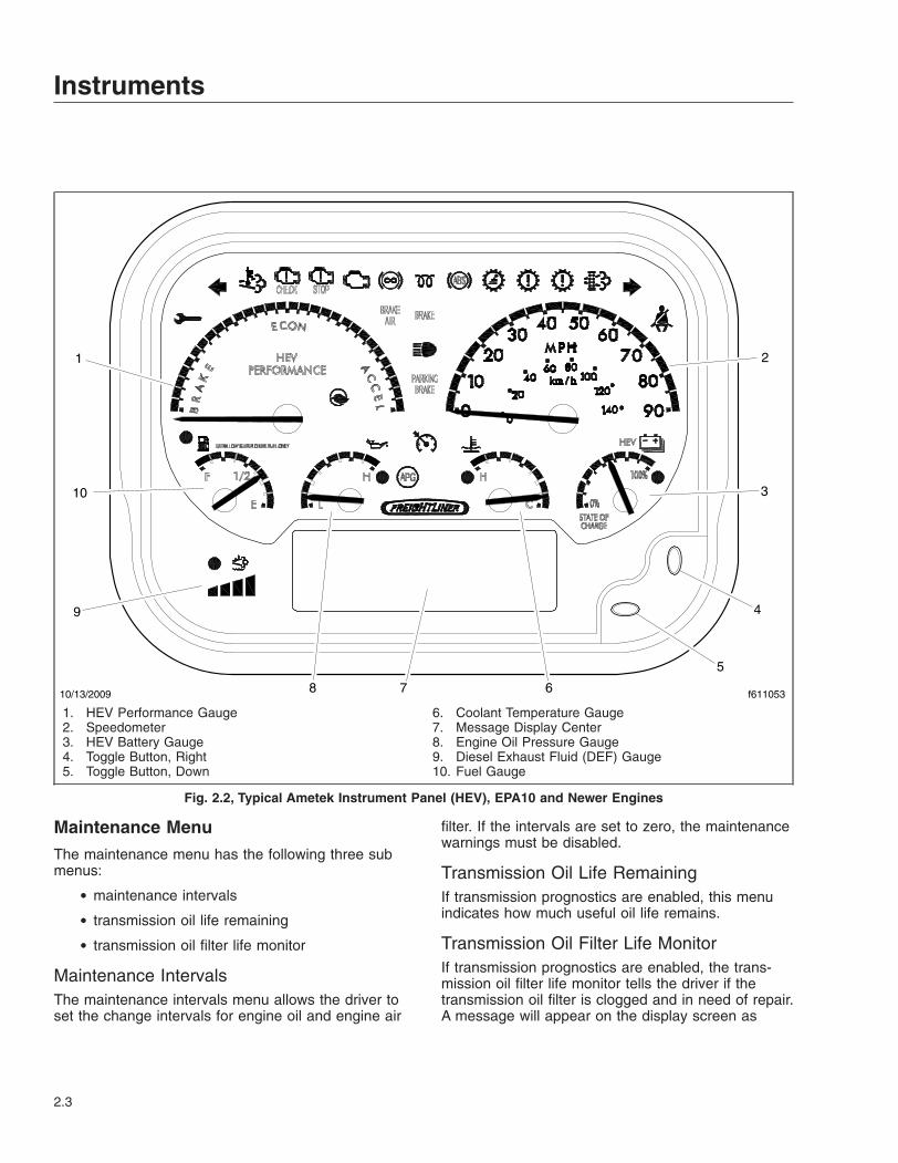
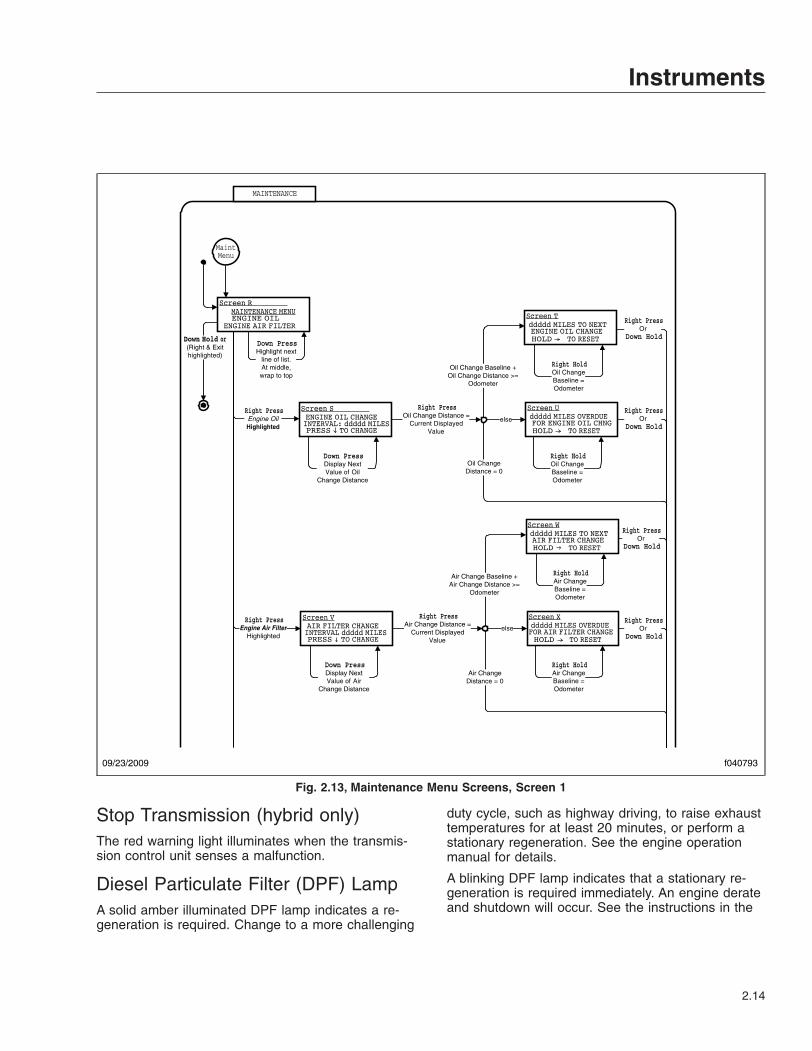
Maintenance MenuThe maintenance menu has the following three submenus:
• maintenance intervals
• transmission oil life remaining
• transmission oil filter life monitor
Maintenance IntervalsThe maintenance intervals menu allows the driver toset the change intervals for engine oil and engine air
filter. If the intervals are set to zero, the maintenancewarnings must be disabled.
Transmission Oil Life RemainingIf transmission prognostics are enabled, this menuindicates how much useful oil life remains.
Transmission Oil Filter Life MonitorIf transmission prognostics are enabled, the trans-mission oil filter life monitor tells the driver if thetransmission oil filter is clogged and in need of repair.A message will appear on the display screen as
10/13/2009 f611053
1 2
9
3
7
10
8 6
4
5
1. HEV Performance Gauge2. Speedometer3. HEV Battery Gauge4. Toggle Button, Right5. Toggle Button, Down
6. Coolant Temperature Gauge7. Message Display Center8. Engine Oil Pressure Gauge9. Diesel Exhaust Fluid (DEF) Gauge10. Fuel Gauge
Fig. 2.2, Typical Ametek Instrument Panel (HEV), EPA10 and Newer Engines
Instruments
2.3

TRANS OIL FILTER FUNCTIONAL or TRANS OILFILTER CLOGGED.
Diagnostic MenuThe diagnostic menu contains the following items:
• engine faults
• transmission faults
• ABS faults
• check outputs
• odometer diagnostics
• check gauges
• check indicators (warning lamps)
• check LCD
• check binary inputs
• check analog inputs
• check datalink
• hardware/software version
All of the items in the diagnostic menu can be ac-cessed by using the toggle buttons and selecting theauxiliary screens. Then navigate to the diagnostic
09/23/2009 f611049
1 2
3
6
7
4
5
1. Fuel Gauge2. Speedometer3. Coolant Temperature Gauge4. Toggle Button, Right
5. Toggle Button, Down6. Message Display Center7. Engine Oil Pressure Gauge
Fig. 2.3, Typical Ametek Instrument Panel (diesel), EPA07-Compliant
Instruments
2.4

sub-menu. Some of the more frequently used diag-nostic menus are described further below.
Engine FaultsThis screen displays engine fault codes that are re-ceived from the engine electronic control unit (ECU).To navigate to the engine fault screen, see Fig. 2.6,screen AA.
Transmission FaultsThis screen displays transmission fault codes thatare received from the transmission ECU. To navigate
to the transmission fault screen, see Fig. 2.6, screenAB.
ABS DiagnosticsThis screen displays Antilock Brake System (ABS)fault codes that are received from the ABS ECU. Tonavigate to the ABS diagnostic screen, see Fig. 2.6,screen AC.
Check GaugesThe check gauges screen allows the driver to seteach gauge as a percentage of scale (either 0, 50, or
09/23/2009 f611050
1 2
3
7
9
8 6
4
5
1. HEV Performance Gauge2. Speedometer3. HEV Battery Gauge4. Toggle Button, Right5. Toggle Button, Down
6. Coolant Temperature Gauge7. Message Display Center8. Engine Oil Pressure Gauge9. Fuel Gauge
Fig. 2.4, Typical Ametek Instrument Panel (HEV), EPA07-Compliant
Instruments
2.5

100%), as shown in the LCD. To navigate to thecheck gauges screen, see Fig. 2.7, AG screens.
SETUP
Down HoldOr (Right & Exit
highlighted)
Down PressCurrent Units =
Metric
Down PressCurrent Units =
English
Current Units =English
Current Units =Metric
Down PressStartup Screen =
Disabled
Down PressStartup Screen =
Enabled
Startup Screen =Enabled
Startup Screen =Disabled
Down PressNot At Min Contrast /
Decrease Contrast
Down PressAt Min Contrast /
Set Contrast to Max
Right PressStartup Screen
highlighted
Right PressSelect Display
Units highlighted
Right PressDisplay Contrast
highlighted
Right PressOr
Down Hold
Right PressOr
Down Hold
Right PressOr
Down Hold
Right PressOr
Down Hold
Right PressOr
Down Hold
Down PressHighlight next
line of list.At middle,wrap to top
Right HoldReset Parameters
Right PressReset Parameters
highlighted
Right PressOr
Down Hold
Right PressOr
Down Hold
AUXILIARYSCREENS
09/23/2009 f040792
Fig. 2.5, Setup Menu Screens
Instruments
2.6
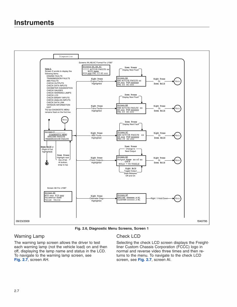
Warning LampThe warning lamp screen allows the driver to testeach warning lamp (not the vehicle load) on and thenoff, displaying the lamp name and status in the LCD.To navigate to the warning lamp screen, seeFig. 2.7, screen AH.
Check LCDSelecting the check LCD screen displays the Freight-liner Custom Chassis Corporation (FCCC) logo innormal and reverse video three times and then re-turns to the menu. To navigate to the check LCDscreen, see Fig. 2.7, screen AI.
Diagnostics
Note 5:Screen Z scrolls to display the following items: ENGINE FAULTS TRANSMISSION FAULTS ABS FAULTS CHECK OUTPUTS CHECK DATA INPUTS ODOMETER DIAGNOSTICS CHECK GAUGES CHECK WARNING LAMPS CHECK LCD CHECK BINARY INPUTS CHECK ANALOG INPUTS CHECK DATA LINK VERSION INFORMATION EXITThe text DIAGNOSTIC MENU remains fixed on the first line.
Down PressDisplay Next Fault
Down PressDisplay Next Fault
Down PressDisplay Next Fault
Right PressOr
Down Hold
Down PressChange to
Next Output
Right PressOr
Down Hold
Right HoldToggle OutputState Between
Off and On
MenuRight Press
Engine FaultsHighlighted
Right PressTrans FaultsHighlighted
Right PressABS FaultsHighlighted
Right PressCheck Outputs
Highlighted
Menu
(Right & Exithighlighted)
Menu
Right PressOr
Down HoldMenu
Right PressOr
Down HoldMenu
Screens AA,AB,AC Format For J1587
Screen AE For J1587
Down PressHighlight next
line of list.At bottom,wrap to top
Right || Hold DownRight Press
Odometer DiagHighlighted
Menu
09/23/2009 f040795
Fig. 2.6, Diagnostic Menu Screens, Screen 1
Instruments
2.7
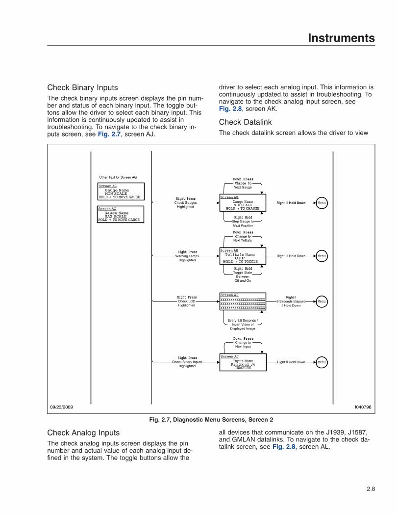
Check Binary InputsThe check binary inputs screen displays the pin num-ber and status of each binary input. The toggle but-tons allow the driver to select each binary input. Thisinformation is continuously updated to assist introubleshooting. To navigate to the check binary in-puts screen, see Fig. 2.7, screen AJ.
Check Analog InputsThe check analog inputs screen displays the pinnumber and actual value of each analog input de-fined in the system. The toggle buttons allow the
driver to select each analog input. This information iscontinuously updated to assist in troubleshooting. Tonavigate to the check analog input screen, seeFig. 2.8, screen AK.
Check DatalinkThe check datalink screen allows the driver to view
all devices that communicate on the J1939, J1587,and GMLAN datalinks. To navigate to the check da-talink screen, see Fig. 2.8, screen AL.
Down PressChange to
Next Gauge
Right HoldStep Gauge toNext Position
Right || Hold Down
Down PressChange to
Next Telltale
Right HoldToggle State
BetweenOff and On
Right || Hold Down
Every 1.5 Seconds /Invert Video of
Displayed Image
Right ||9 Seconds Elapsed
|| Hold Down
Down PressChange toNext Input
Right || Hold Down
Right PressCheck Gauges
Highlighted
Right PressWarning Lamps
Highlighted
Right PressCheck LCDHighlighted
Right PressCheck Binary Inputs
Highlighted
Menu
Menu
Menu
Menu
Other Text for Screen AG
09/23/2009 f040796
Fig. 2.7, Diagnostic Menu Screens, Screen 2
Instruments
2.8

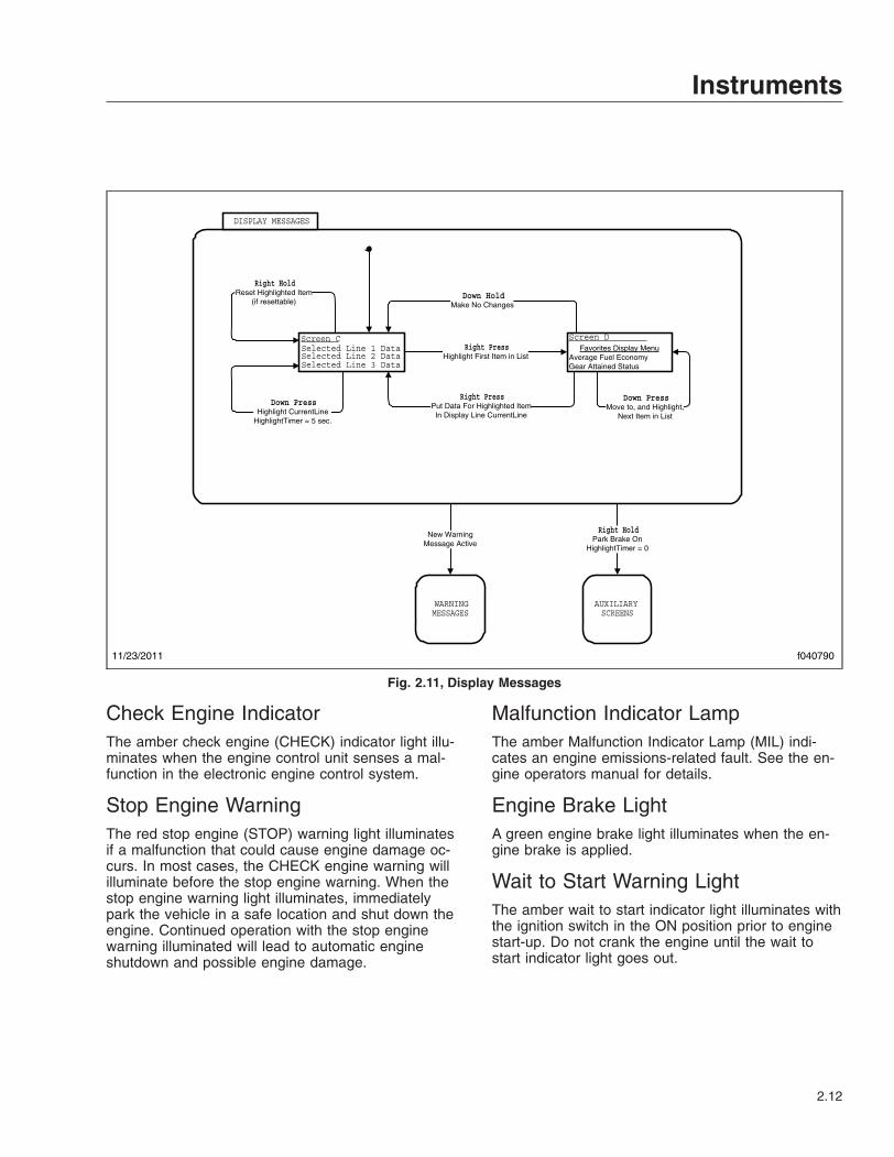
Menu NavigationThe menu navigation road maps are provided to il-lustrate the screens that are available in the menusystem. The paths to specific screens are shown,along with instructions for using the toggle buttons tomove from one screen to another. Refer to the roadmaps to change items shown in lines one, two, andthree of the display screen, view the setup screens,diagnostics, etc. See Fig. 2.5, Fig. 2.6, Fig. 2.7,Fig. 2.8, Fig. 2.9, Fig. 2.10, Fig. 2.11, Fig. 2.12,Fig. 2.13, Fig. 2.14, Fig. 2.15, Fig. 2.16, andFig. 2.17.
IMPORTANT: Follow the steps below to changethe three items (also known as favorites) shownin the message display center. The messagedisplay center is referred to as screen C inFig. 2.11.
1. With the vehicle in park, turn the ignition to ON,and allow the self test to complete.
2. Press the down toggle button to select an item tochange. The selected item will now be high-lighted.
3. Press the right toggle button once to enter thefavorites display menu, shown in Fig. 2.11, asscreen D.
4. Use the down toggle button to scroll through theavailable items.
5. Highlight the new item, then press the righttoggle button. The selected item will now appearin the message display center.
Warning and Indicator LightsGeneral InformationThe warning and indicator lights are located in theinstrument panel and contain all of the standard andoptional warning and indicator lights. See Fig. 2.18and Fig. 2.19 for diesel and HEV compliant warningand indicator lights respectively.
02/06/2012 f040797
AUXILIARYSCREENS
SOFTWARE VER: x.yyCONFIG: cccccccHARDWARE VER: z
Right || Hold DownRight Press
Version InformationHighlighted
Menu
Screen AM
Input NamePin pp of 26xx.x Units
Down PressChange toNext Input
Right || Hold Down
ECUs on Data BusJ1939 SA xxJ1939 SA yy
Down PressScroll ScreenDown 1 Line
Right || Hold Down
Right PressCheck Analog Inputs
Highlighted
Right PressCheck Data Link
Highlighted
Menu
Menu
Screen AK
Screen AL
Fig. 2.8, Diagnostic Menu Screens, Screen 3
Instruments
2.9

Maintenance Warning LightWhen the amber maintenance warning light illumi-nates, the message display center will alert the driveras follows:
• Oil Change Required—alerts the driver that theengine has reached the recommended oilchange interval.
H*
SELF TEST
DISPLAY MESSAGES
WARNING MESSAGES
Active WarningMessages
No Warnings Active orAll Warnings
Acknowledged
Right HoldPark Brake On
IGNITION ON
IGNITIONOFF
IgnitionOff
Ignition On orHeadlamps On or
Marker Lamps On orPark Brake Off
IgnitionOn
Ignition Off &Headlamps Off &
Marker Lamps Off &Park Brake On
Self TestEnabled
AUXILIARYSCREENS
ACTIVE
Ignition Off &( Headlamps On or
Marker Lamps On orPark Brake Off )
Ignition On
USB Drive Present &Park Brake On &
Vehicle Speed = 0 &Not in Self Test
H*
NORMAL MODE
DOWNLOADMODE
09/23/2009 f040788
Fig. 2.9, Ignition On, Normal Mode
Instruments
2.10

• Air Filter Reminder—the air filter requireschecking or replacement.
• Transmission Prognostics Warning—if thetransmission has prognostics enabled.
Left-Turn Signal ArrowThe green left-turn signal arrow flashes on and offwhenever the outside left-turn signal lights are flash-ing. Both turn signal arrows flash when the hazardwarning flasher is on.
High Exhaust System Temperature(HEST) LampIndicates potentially hazardous exhaust temperaturesat the outlet of the tail pipe if speed is below 5 mph
(8 km/h). It does not signify the need for service; itonly alerts the vehicle operator of high exhaust tem-peratures. See the engine operation manual for de-tails.
The amber HEST lamp will illuminate as follows:
• Slow (10-second) flash, indicates a regenera-tion is in progress, and the driver is not control-ling the engine idle speed.
• Solid illumination indicates a regeneration is inprogress, with high exhaust temperatures atthe outlet of the tailpipe, if the speed is below5 mph (8km/h). It does not signify the need forservice; it only alerts the vehicle operator ofhigh exhaust temperatures. See the engineoperator’s manual for details.
SELF TEST
DISPLAY MESSAGES
XXXXXXXXXXXXXXXXXXXXXXXXXXXXXXXXXXXXXXXXXXXXXXXXXXXXXXXXXXXXXXXXXX
XXXXXXXXXXXXXXXXXXXXXXXXXXXXXXXXXXXXXXXXXXXXXXXXXXXXXXXXXXXXXXXXXX
Screen Displayedfor 1.5 Seconds
Screen Displayedfor 1.5 Seconds
Startup Screen Enabled
The Self Test screens display the FCCClogo in normal video (Screen A) and in
reverse video (Screen B)
Startup Screen Disabled
Screen A
Screen B
02/06/2012 f040789
Fig. 2.10, Self Test
Instruments
2.11
Check Engine IndicatorThe amber check engine (CHECK) indicator light illu-minates when the engine control unit senses a mal-function in the electronic engine control system.
Stop Engine WarningThe red stop engine (STOP) warning light illuminatesif a malfunction that could cause engine damage oc-curs. In most cases, the CHECK engine warning willilluminate before the stop engine warning. When thestop engine warning light illuminates, immediatelypark the vehicle in a safe location and shut down theengine. Continued operation with the stop enginewarning illuminated will lead to automatic engineshutdown and possible engine damage.
Malfunction Indicator LampThe amber Malfunction Indicator Lamp (MIL) indi-cates an engine emissions-related fault. See the en-gine operators manual for details.
Engine Brake LightA green engine brake light illuminates when the en-gine brake is applied.
Wait to Start Warning LightThe amber wait to start indicator light illuminates withthe ignition switch in the ON position prior to enginestart-up. Do not crank the engine until the wait tostart indicator light goes out.
DISPLAY MESSAGES
Selected Line 1 DataSelected Line 2 DataSelected Line 3 Data
Favorites Display MenuAverage Fuel EconomyGear Attained Status
Right Press Highlight First Item in List
Down PressMove to, and Highlight,
Next Item in List
Right PressPut Data For Highlighted ItemIn Display Line CurrentLine
Down HoldMake No Changes
Down Press Highlight CurrentLine
HighlightTimer = 5 sec.
WARNING MESSAGES
AUXILIARY SCREENS
New WarningMessage Active
Right HoldPark Brake On
HighlightTimer = 0
Right Hold Reset Highlighted Item
(if resettable)
Screen C Screen D
11/23/2011 f040790
Fig. 2.11, Display Messages
Instruments
2.12

ABS IndicatorThe amber ABS indicator light illuminates when thereis a malfunction in the vehicle antilock brake system(ABS).
Shift Inhibit IndicatorOn vehicles equipped with Allison 2100/2200/2500series transmissions, the amber shift inhibit indicatorlight illuminates whenever all conditions for safetransmission shifting have not been met.
Check Transmission IndicatorThe amber check transmission indicator illuminateswhen the temperature of the transmission fluid goesabove the preset level set by the transmission manu-facturer.
For more information, see the transmission manufac-turer’s manual provided with the vehicle.
AUXILIARY SCREENS
SETUP MAINTENANCE DIAGNOSTICS
Down PressHighlight next
line of list.At middle,wrap to top
MAINTENANCE
DIAGNOSTICS
Right PressSetup
highlighted
Right PressDiagnosticshighlighted
Right PressMaintenancehighlighted
SETUP
SETUP.
DISPLAYMESSAGES
Down Hold
TRIP DATARight Press
Trip Datahighlighted
Screen G
02/06/2012 f040791
Fig. 2.12, Auxiliary Screens
Instruments
2.13
Stop Transmission (hybrid only)The red warning light illuminates when the transmis-sion control unit senses a malfunction.
Diesel Particulate Filter (DPF) LampA solid amber illuminated DPF lamp indicates a re-generation is required. Change to a more challenging
duty cycle, such as highway driving, to raise exhausttemperatures for at least 20 minutes, or perform astationary regeneration. See the engine operationmanual for details.
A blinking DPF lamp indicates that a stationary re-generation is required immediately. An engine derateand shutdown will occur. See the instructions in the
MAINTENANCE
(Right & Exithighlighted)
Right PressEngine OilHighlighted
Right PressEngine Air Filter
Highlighted
Down PressHighlight next
line of list.At middle,wrap to top
MaintMenu
Down PressDisplay NextValue of Air
Change Distance
Air Change Baseline +Air Change Distance >=
Odometer
Air ChangeDistance = 0
else
Right PressAir Change Distance =
Current DisplayedValue
Right HoldAir ChangeBaseline =Odometer
Right HoldAir ChangeBaseline =Odometer
Right PressOr
Down Hold
Right PressOr
Down Hold
Down PressDisplay NextValue of Oil
Change Distance
Oil Change Baseline +Oil Change Distance >=
Odometer
else
Right PressOil Change Distance =
Current DisplayedValue
Right HoldOil ChangeBaseline =Odometer
Right HoldOil ChangeBaseline =Odometer
Right PressOr
Down Hold
Right PressOr
Down Hold
Oil ChangeDistance = 0
09/23/2009 f040793
Fig. 2.13, Maintenance Menu Screens, Screen 1
Instruments
2.14

engine manufacturer’s operator’s manual to performa stationary regeneration.
Right-Turn Signal ArrowThe green right-turn signal arrow flashes on and offwhenever the outside right-turn signal lights areflashing. Both turn signal arrows flash when the haz-ard warning flasher is on.
Fasten Seat Belt WarningThe red fasten seat belt warning light (seat belt icon)illuminates for 30 seconds after the ignition switch isturned on.
WARNINGIf the vehicle is equipped with an air suspensionsystem, do not move the vehicle with the air sus-pension deflated. Doing so could result in a lossof vehicle control, possibly causing personal in-jury and property damage.
Air Brake IndicatorThe red air brake indicator activates if the pneumaticbrake system air is low, or if the air suspension islow.
Hydraulic Brake System WarningThe red brake system warning illuminates if there isa hydraulic brake system failure, or if the vehicle ispowered and the engine is not running.
Headlight High-Beam IndicatorThe blue high-beam indicator light illuminates whenthe headlights are switched to the high-beam posi-tion.
Parking Brake On IndicatorThe red parking brake indicator will flash for two min-utes if the parking brake is not set when the ignitionis turned off. It will also flash if the park brake is set
02/06/2012 f040794
AUXILIARYSCREENS
Right HoldSend SPN 1584 = 39
Right PressTransmission
Oil LifeHighlighted
Right PressTransmission
Oil FilterHighlighted
Right PressOr
Down Hold
Right PressOr
Down Hold
Right PressOr
Down Hold
MaintMenu
Right HoldSend SPN 1584 = 37
Right PressOr
Down Hold
Fig. 2.14, Maintenance Menu Screens, Screen 2
Instruments
2.15

and the vehicle is moving at a speed of 2 mph (3km/h) or more. The emergency buzzer will sounduntil the parking brake is released and the driver dis-play screen will show a PARK BRAKE SET mes-sage.
Cruise Control IndicatorA green indicator illuminates when the cruise controlis activated.
Auxiliary Power Generator (hybridonly)A green indicator illuminates when the auxiliarypower generator is activated.
Speedometer and TachometerStandard speedometers are shown in Fig. 2.1,Fig. 2.2, Fig. 2.3, and Fig. 2.4, item 2 respectively.Optional speedometer faces are available. TheNAFTA version (not shown) of the speedometer face
Trip Data
AUXILIARYSCREENS
Note 6:Screen AO scrolls to display the following items:
Trip TimeIdle TimeMax RPMAvg RPMMax SpeedAvg SpeedAvg Fuel EconomyReset AllExit
Right PressReset AllHighlighted
Correct Passcode /Reset Trip
Data
Right Press
Down PressHighlight next
line of list.At bottom,wrap to top
(Right & Exithighlighted)
Wrong Passcode /Down Press
Right Press
09/23/2009 f040798
Fig. 2.15, Trip Data
Instruments
2.16

reverses this arrangement, with km/h in larger num-bers.
A tachometer is available as an option. See "OptionalInstruments."
Standard InstrumentsFuel Level GaugeThe fuel level gauge indicates the amount of fuel inthe fuel tank.
Low Fuel Warning LightThe low fuel warning light illuminates when the fuellevel in the fuel tank drops to a predetermined level.When the low fuel warning light illuminates, refill thefuel tank as soon as possible.
Engine Oil Pressure Gauge
NOTICEA sudden decrease or absence of oil pressuremay indicate mechanical failure. Bring the vehicleto a safe stop and investigate the cause to pre-vent further damage. Do not operate the engineuntil the cause has been determined and cor-rected.
The engine oil pressure gauge is mission-critical. Ifthe engine oil pressure falls below preset levels, thecheck engine light will illuminate. If the conditiondoes not improve, the CHECK engine light will alsoilluminate and the buzzer will sound. At this point, theengine will derate or shut down, depending on thetype of engine protection system installed.
02/06/2012 f040799
WARNING MESSAGES
DISPLAY MESSAGES
H*
WARNING Warning Message
No WarningMessages in List /
Msg Displayed for 5 Sec. /Display Next Entry in
Warning Message List
Any Button Press
/Display 1st Message
in WarningMessage List
Screen AN
Fig. 2.16, Warning Messages
Instruments
2.17

Low Oil Pressure WarningThe low oil pressure (oil can symbol) warning lightilluminates and a buzzer sounds when the oil pres-sure falls below the minimum oil pressure recom-mended by the engine manufacturer.
High Coolant Temperature WarningA red high coolant temperature (thermometer sym-bol) warning light illuminates when the engine is run-ning and the engine coolant temperature exceeds themaximum coolant temperature recommended by theengine manufacturer.
Coolant Temperature Gauge
NOTICEA sudden increase in coolant temperature mayindicate engine or cooling system failure. Bringthe vehicle to a safe stop and investigate thecause to prevent further damage. Do not operate
the engine until the cause has been determinedand corrected.
The coolant temperature gauge is mission-critical. Ifthe coolant temperature rises above preset levels,the check engine light will illuminate. If the conditiondoes not improve, the CHECK engine light will alsoilluminate and the buzzer will sound. At this point, theengine will derate or shut down, depending on thetype of engine protection system installed.
Primary and Secondary Air PressureGauges
WARNINGIf air pressure falls below minimum pressure, thebraking ability of the vehicle will be limited. Slowthe vehicle down and bring it to a gradual stop.Do not attempt to move the vehicle until air pres-sure has risen above the minimum level. Movinga vehicle without adequate braking power could
IGNITION OFF
Park Brake On
Park Brake On
Park Brake Off
IGNITIONON
Headlamps Off &Marker Lamps Off &
Park Brake On
Ignition On
02/06/2012 f040800
Fig. 2.17, Ignition Off (shown when ignition is keyed OFF)
Instruments
2.18

cause an accident resulting in property damage,personal injury, or death.
Air pressure gauges register the pressure in the pri-mary and secondary air systems. Normal pressurewith the engine running is 100 to 120 psi (689 to 827kPa) in both systems.
Air pressure gauges are required on all vehicles withair brakes. A low-air-pressure warning light andbuzzer, connected to both the primary and secondarysystems, activate when air pressure in either systemdrops below a minimum pressure of 65 to 75 psi(448 to 517 kPa).
When the engine is started, the warning light andbuzzer remain on until air pressure in both systemsexceeds minimum pressure.
Optional InstrumentsAir Intake Restriction GaugeAn intake-air restriction indicator, mounted in the en-gine compartment, measures the vacuum on the en-gine side of the air cleaner at the air cleaner outlet.See Fig. 2.20.
Air intake restriction vacuum is measured in inchesof water (inH2O). For vehicles equipped with agraduated indicator or a restriction gauge on thedash, check the gauge with the engine off. If restric-tion reaches 25 inH2O, replace the air cleaner ele-ment. Reset the indicator by pressing the button onthe bottom.
NOTE: Rain or snow can wet the filter andcause a higher than normal reading temporarily.
09/21/2009 f611052
1
2
3 4 5 6 7 8 9 10 11 12 13
14
15
1920
17
18
16
1. Maintenance Warning Light2. Left-Turn Signal Arrow3. High Exhaust System
Temperature (HEST) Lamp4. Check Engine Indicator5. Stop Engine Warning6. Malfunction Indicator Lamp7. Engine Brake Light
8. Wait to Start Warning Light9. ABS Indicator10. Shift Inhibit Indicator11. Check Transmission Indicator12. Stop Transmission (hybrid only)13. Diesel Particulate Filter (DPF)
Lamp14. Right-Turn Signal Arrow
15. Fasten Seat Belt Warning16. Air Brake Indicator (low air
warning)17. Hydraulic Brake System Warning18. Headlight High-Beam Indicator19. Cruise Control Indicator20. Parking Brake On Indicator
Fig. 2.18, Warning Lights, Diesel
Instruments
2.19

Single Air Pressure Gauge forHydraulic Brakes with Air ProvisionThis option is only available with hydraulic brakeswith air provision.
Transmission Fluid TemperatureGaugeWith an Allison automatic transmission, the transmis-sion fluid temperature gauge reading should not ex-ceed 250°F (121°C) during normal operation. If thisoccurs, a warning light will activate to alert the driver.
TachometerA tachometer indicates engine speed in revolutionsper minute (rpm) and serves as a guide for shiftingthe transmission and for keeping the engine in theappropriate rpm range. For low idle and rated rpm,see the engine identification plate.
09/21/2009 f611054
1
2
3 4 5 6 7 8 9 10 11 12 13
14
15
2021
17
18
16
19
1. Maintenance Warning Light2. Left-Turn Signal Arrow3. High Exhaust System
Temperature (HEST) Lamp4. Check Engine Indicator5. Stop Engine Warning6. Malfunction Indicator Lamp7. Engine Brake Light
8. Wait to Start Warning Light9. ABS Indicator10. Shift Inhibit Indicator11. Check Transmission Indicator12. Stop Transmission Indicator13. Diesel Particulate Filter (DPF)
Lamp14. Right-Turn Signal Arrow
15. Fasten Seat Belt Warning16. Air Brake Indicator (low air
warning)17. Hydraulic Brake System Warning18. Headlight High-Beam Indicator19. Parking Brake On Indicator20. Cruise Control Indicator21. Auxiliary Power Generator
Fig. 2.19, Warning Lights, Hybrid Electric Vehicle
01/18/95 f600148a
Fig. 2.20, Air Intake Restriction Gauge
Instruments
2.20

3
ControlsIgnition Switch and Key . . . . . . . . . . . . . . . . . . . . . . . . . . . . . . . . . . . . . . . . . . . . . . . . . . . . . . . . . . . . 3.1Electrical System General Information . . . . . . . . . . . . . . . . . . . . . . . . . . . . . . . . . . . . . . . . . . . . . . . . 3.1Lighting Controls . . . . . . . . . . . . . . . . . . . . . . . . . . . . . . . . . . . . . . . . . . . . . . . . . . . . . . . . . . . . . . . . . . 3.1Turn Signal Switch . . . . . . . . . . . . . . . . . . . . . . . . . . . . . . . . . . . . . . . . . . . . . . . . . . . . . . . . . . . . . . . . 3.3Horn Controls . . . . . . . . . . . . . . . . . . . . . . . . . . . . . . . . . . . . . . . . . . . . . . . . . . . . . . . . . . . . . . . . . . . . 3.3Powertrain Controls . . . . . . . . . . . . . . . . . . . . . . . . . . . . . . . . . . . . . . . . . . . . . . . . . . . . . . . . . . . . . . . 3.3Braking and Steering Controls . . . . . . . . . . . . . . . . . . . . . . . . . . . . . . . . . . . . . . . . . . . . . . . . . . . . . . . 3.5Dash-Mounted Controls . . . . . . . . . . . . . . . . . . . . . . . . . . . . . . . . . . . . . . . . . . . . . . . . . . . . . . . . . . . . 3.6

Ignition Switch and KeyOn most vehicles, the ignition switch can be turnedto four positions: ACCESSORY, OFF, ON, andSTART. See Fig. 3.1. An optional three-position key-less ignition switch does not have the ACCESSORYposition.
The key can be inserted and removed only from theOFF position. The headlights (low beams), brakelights, fog lights, dome lights, clearance lights, turnsignals, hazard warning lights, and the parking lightsoperate with the ignition switch in the OFF position,regardless of whether the key is inserted.
Turn the key fully clockwise to the START position,only when starting the engine. When the enginestarts, release the key. When released, the key willrotate counterclockwise to the ON position.
In the ON position (key turned 45 degrees clock-wise), all electrical systems are operable. The warn-ing lights and the buzzer for low engine oil pressureoperate until the engine is started and minimum en-gine oil pressure is achieved.
Electrical System GeneralInformationThe Walk-In Van chassis uses multiple electrical sig-nals that are carried along a simplified set of wires,reducing the size of wiring bundles. There are signifi-cantly fewer wires overall, meaning less chance ofdamage, shorts, and other problems. The information
in this chapter is to help familiarize the driver with thebasic electrical system. Servicing the electrical sys-tem should be done only by qualified technicians.Special skills and equipment are required. Take thevehicle to an authorized Freightliner service facilityfor repairs.
WARNINGDo not attempt to modify, add, splice, or removeelectrical wiring on this vehicle. Doing so coulddamage the electrical system and result in a firethat could cause serious personal injury or prop-erty damage.
Battery Disconnect Switch (optional)Some Walk-In Van chassis may be equipped with abattery disconnect switch that can be used to preventunwanted drain from the vehicle battery when thevehicle is not in use or is in storage. It can also rap-idly disconnect from power supplies in the event ofan emergency. Mounting locations may vary. SeeFig. 3.2.
Lighting ControlsThe lighting controls mentioned under this headinggenerally operate through switches located on thedash.
07/10/96
1
2
34
f601179
1. Accessory (optional)2. Off
3. On4. Start
Fig. 3.1, Ignition Switch Positions
f545041
2
3
1
05/16/2007
1. Power-Off Position2. Battery Disconnected (red area)3. Power-On Position (green area)
Fig. 3.2, Battery Disconnect Switch (optional)
Controls
3.1

Headlight and Panel Light ControlsThe control knob for the headlights, side markerlights, taillights, parking lights, license plate lights,and panel lights is located on the instrument panel.See Fig. 3.3 and Fig. 3.4. Control knob positions areas follows:
• All lights are off if the knob is pushed all theway in.
• If pulled out to the first stop, all lights are onexcept the headlights.
• If pulled all the way out, all lights including theheadlights are on.
• Turn the knob to the right to brighten the panellights or turn it to the left to dim them.
• Turn the knob all the way to the left (past theclick stop) to operate the courtesy lights.
Headlight High-Beam/Dimmer SwitchThe headlight high beams are activated by pullingthe turn signal lever toward the driver. When theheadlights are on high beam, the high-beam indicatorlight comes on in the instrument panel.
Hazard Warning Light TabThe hazard warning light tab is located on the steer-ing column under the turn signal lever. See Fig. 3.5.Pull the tab out to turn on the hazard warning lights.When the hazard warning light tab is pulled out, all ofthe turn signal lights and both of the indicator lights
on the control panel will flash. To cancel the warninglights, press the tab in.
An additional hazard warning light control knob maybe installed on the dash near the headlight controls.To activate the hazard warning lights, pull this knobout.
A B C D
E08/01/96 f601188
A. OffB. All Lights Except HeadlightsC. All Lights including HeadlightsD. Panel Light BrightnessE. Courtesy Lights
Fig. 3.3, Headlight Control Knob
f60126902/24/97
1
2
34
1. Windshield Wiper/Washer Control Knob2. Headlight Control Knob3. Cargo Light Switch4. Cab Fan Switch
Fig. 3.4, Left-Hand Dash Panel
11/27/2007 f462122
Fig. 3.5, Hazard Warning Light Tab
Controls
3.2

Turn Signal SwitchThe turn signal switch lever is mounted on the steer-ing column. See Fig. 3.6. Pushing the lever downturns on the left-turn signal lights; pulling the lever upturns on the right-turn signal lights. When one of thesignal lights is on, a green indicator light flashes atthe left or right side of the warning and indicator lightpanel. When the turn is completed, the signal willcancel and the lever will return to the neutral posi-tion.
NOTE: The hazard warning light indicator on theturn signal lever is to instruct the driver to pullthe hazard warning light tab that is locatedunder the turn signal lever.
Horn ControlsTo sound the electric horn, push the horn icon on thesteering wheel. See Fig. 3.7.
Powertrain ControlsAllison Automatic TransmissionsAllison automatic transmissions have either 6 or 7shift positions on the selector lever. See Fig. 3.8.The selector lever is lighted for night driving. Elec-tronically controlled transmissions have a push-button selector. See Chapter 5 for complete trans-mission operating instructions.
f545174
1
2
03/16/2015
1. Headlight High-Beam/Dimmer Switch2. Hazard Warning Light Indicator
Fig. 3.6, Turn Signal Lever
f462078a06/28/2007
1
1. Horn Pad/Icon
Fig. 3.7, Horn Control
1
P
R
N
3
D
4
09/12/2006 f261381
Fig. 3.8, T-Handle Shift Control (typical)
Controls
3.3

Cruise Control (optional)
WARNINGDo not use the cruise control system when driv-ing conditions do not permit maintaining a con-stant speed, such as heavy traffic or on roadsthat are winding, icy, snow covered, slippery, orroads with a loose driving surface. Failure to fol-low this precaution could cause a collision orloss of vehicle control, possibly resulting in per-sonal injury or property damage.
NOTE: The maximum cruise control speed al-lowed is 75 mph (121 km/h). However, somevehicles may have a maximum cruise controlspeed that is lower than 75 mph (121 km/h), ifthe vehicle was ordered that way.
The cruise control is activated by two dash switches.See Fig. 3.9.
• The On/Off Switch—this two-position rockerswitch bears the legend SPD CNTL on thelower half of the switch. When the cruise con-trol is on, an amber light illuminates in the toppart of the switch.
• The Set/Resume Switch—this three-positionpaddle switch bears the legend RES/ACCabove the paddle and SET/CST below thepaddle.
1. To cruise at a particular speed, do these steps:
1.1 Press the upper half of the On/Off (rocker)switch on the instrument panel.
1.2 Hold the accelerator pedal down until thespeedometer reaches the desired speed.
1.3 Momentarily lower the paddle of the Set/Resume switch to SET/CST.
2. To disengage the cruise control, do these steps:
2.1 Press down the brake pedal (on automaticor manual transmission) or
Press down the clutch pedal (on manualtransmission only)
2.2 Press the lower half of the On/Off (rocker)switch on the instrument panel.
3. To resume a preselected cruise speed, do thesesteps:
3.1 If the On/Off (rocker) switch on the instru-ment panel is off, turn it on.
3.2 Momentarily raise the paddle of the Set/Resume switch to RES/ACC. Cruise willreturn to the last speed selected.
NOTE: If the ignition is shut off, the speedmemory will be lost.
4. To adjust cruise speed up, raise the paddle ofthe Set/Resume switch to RES/ACC and hold itthere until the vehicle accelerates to the newspeed, as desired.
5. To adjust the cruise speed down, lower thepaddle of the Set/Resume switch to SET/CSTand hold it there until the vehicle decelerates tothe new speed, as desired.
NOTE: For more information about cruise con-trol operation, see the engine manufacturer’sservice manual.
09/13/2001
1
2
f610510
To turn the cruise control on, press the upper half of theOn/Off (rocker) switch. To turn cruise control off, pressthe lower half of the On/Off (rocker) switch.1. Cruise Control On/Off (rocker) Switch2. Cruise Control Set/Resume (paddle) Switch
Fig. 3.9, Cruise Control Switches, Dash-Mounted
Controls
3.4

Manual Dump Valve (optional)On vehicles equipped with a manual dump valve,there are two ways to deflate the rear suspension.With the key in the OFF position, toggle the dumpvalve into the "lower" position. If the key is in the ONposition, the parking brake must be set (ON) beforethe dump valve is toggled into the "lower" position.
NOTE: If the key is turned to the ON positionand the parking brake is not engaged, the over-ride will cause reinflation of the air ride system.
Backup Alarm (optional)An optional backup alarm, sounds when Reverse ®)gear is engaged. Check the operation of the backupalarm daily, if so equipped.
Braking and Steering ControlsParking Brake ControlHand-Operated Parking BrakeOn all vehicles, a parking brake control lever is lo-cated to the left of the steering column. To apply theparking brake, depress the brake pedal, then pull upon the parking brake lever. To release the parkingbrake, depress the brake pedal and push the parkingbrake lever all the way down.
IMPORTANT: Take care to hold on to the park-ing brake lever while releasing it. Do NOT allowthe lever to slam down while releasing it.
NOTICEOvertightening of the knob can lead to cablebreakage and/or damage to the knob and lever.
If the parking brake does not hold the vehicle se-curely, depress the brake pedal and release theparking brake. Turn the knob on the end of the leverclockwise to increase the parking brake application.
If the parking brake still doesn’t hold the vehicle se-curely (after adjustment), check the brake liningthickness. For instructions, see Group 42 of theWalk-In Van Chassis Maintenance Manual.
Hydraulic Parking Brake (optional)To apply the hydraulic parking brake, pull the yellowknob labeled PARKING BRAKE on the dash panel.
In order to release the hydraulic parking brake, theengine must be running (hydraulic pressure isneeded to release the brake) and the gear selectormust be in the Neutral (N) position. To release theparking brake, push the knob in.
CAUTIONOn vehicles with hydraulic parking brakes, lossof all hydraulic pressure will cause the parkingbrake to automatically engage.
NOTE: If the gear selector is not in the Neutral(N) position and the parking brake is on, abuzzer will sound to let the driver know to placethe gear selector in the Neutral (N) position.
If the ignition key is in the OFF position and theparking brake is not applied, a buzzer will soundto let you know that you should apply the park-ing brake.
With the engine shut down, the hydraulic pumpwill actuate with your foot on the brake pedal;this could cause the battery to run down. If theengine is inoperable, see the "Emergency Re-lease of Parking Brake" procedure that follows.
Emergency Release of Parking Brake(automatic transmission)If your engine will not start and you want to releasethe parking brake, do the following. Block the wheelsand turn the ignition switch to the ON position.
NOTICEDo not crank the engine for more than 30 sec-onds at a time during any of the following proce-dures. Wait two minutes after each try to allowthe starter to cool. Failure to do so could causestarter damage.
Use the ignition switch to turn the engine over sev-eral times with the gear shift selector in the Neutral(N) position and the parking brake knob in the re-leased (pushed) position.
NOTE: The emergency release will not work inall cases. The system requires hydraulic fluid toprovide pressure for the procedure to work.Since the system is pressurized when the brakeis released, the parking brake will come back on
Controls
3.5

in 10 minutes, or longer depending on internalpressure.
Tilt/Telescope Steering ColumnLever Adjustment (optional)To change the position of the steering wheel, pull thelever upward and move the steering wheel to the de-sired position. See Fig. 3.10. Release the lever tolock the position. The steering wheel can be tilted upto provide easier exit and reentry.
If the chassis is equipped with a telescoping steeringcolumn, push the lever down and extend or retractthe steering wheel as desired.
Foot Pedal Adjustment (optional)If the tilt/telescope steering column is equipped witha foot pedal adjustment, depress the foot pedal tomove the steering column to the desired position.Release the foot pedal to lock the position. SeeFig. 3.11.
Dash-Mounted ControlsAftertreatment System (ATS) RegenSwitch
A regen switch is located on or under the dash withwhich the driver can control two states. SeeFig. 3.12. These include:
• Request regeneration
• Default (automatic regeneration)
10/12/2007 f462115
1
1. Tilt/Telescope Lever
Fig. 3.10, Tilt/Telescope Steering Column with LeverAdjustment
f462016
1
05/11/2005
1. Tilt/Telescope Foot Pedal
Fig. 3.11, Tilt/Telescope Steering Column with FootPedal Adjustment
f61084803/09/2012
RGEN
Fig. 3.12, ATS Regen Switch
Controls
3.6

See the engine operation manual for details onoperation of the regen switch.
Low Idle Adjustment SwitchNOTE: The low idle adjustment switch is notavailable on hydraulic hybrid units.
On some vehicles equipped with Cummins ISB en-gines, the engine low idle speed can be adjusted in25 rpm increments with a low idle adjustment switch.On these vehicles, the engine control unit is pro-grammed to allow low idle speeds between 700 and875 rpm.
Windshield Wiper SwitchThe windshield wipers are controlled by a dash-mounted knob. See Fig. 3.4. For a single wipe cycle,turn the knob counterclockwise. Hold it in this posi-tion until the wipers start, then release the knob. Forsteady wiping at low speed, turn the knob clockwiseone position. For high-speed wiping, turn the knobclockwise to the high-speed position.
NOTE: Heavy snow or ice can overload thewiper motor. A circuit breaker will stop the motoruntil it cools. Make sure that the windshield iscleared of snow or ice to prevent a circuit over-load.
Windshield Washer SwitchPush in and hold the windshield wiper control knobuntil the desired amount of washer fluid is sprayedon the windshield. See Fig. 3.4. The wipers will oper-ate on low speed until they are turned off.
Controls
3.7

4
EnginesEngine Starting . . . . . . . . . . . . . . . . . . . . . . . . . . . . . . . . . . . . . . . . . . . . . . . . . . . . . . . . . . . . . . . . . . . 4.1Engine Operation . . . . . . . . . . . . . . . . . . . . . . . . . . . . . . . . . . . . . . . . . . . . . . . . . . . . . . . . . . . . . . . . . 4.2High Idle Options . . . . . . . . . . . . . . . . . . . . . . . . . . . . . . . . . . . . . . . . . . . . . . . . . . . . . . . . . . . . . . . . . 4.3Exhaust Aftertreatment System (ATS) . . . . . . . . . . . . . . . . . . . . . . . . . . . . . . . . . . . . . . . . . . . . . . . . . 4.3Engine Shutdown . . . . . . . . . . . . . . . . . . . . . . . . . . . . . . . . . . . . . . . . . . . . . . . . . . . . . . . . . . . . . . . . . 4.9

Engine StartingGeneral InformationThis engine chapter is to serve as a guide for bestpractices only. Each make and model engine mayhave operating characteristics that are unique to thatparticular engine, and will be documented in the en-gine manufacturer’s literature. Always refer to specificinstructions and recommendations from the enginemanufacturer.
NOTE: Before starting the engine, read Chap-ter 2 and Chapter 3 of this manual for detailedinformation on how to read the instruments andoperate the controls.
Normal Starting
WARNINGDo not use any starting aid, such as ether, in en-gines with an air intake heater. This could causean explosion and serious personal injury ordeath.
NOTE: Cummins engines are run on a dyna-mometer before being shipped from the factory.They do not require a break-in period.
IMPORTANT: Special break-in oils are not rec-ommended for new or rebuilt Cummins engines.
NOTICEIf a vehicle does not start on the first attempt,make sure that the engine has completelystopped rotating before reapplying the starterswitch. Failure to do so can cause the pinion torelease and re-engage, which could cause ringgear and starter pinion damage.
Moving a vehicle with the starter and/or using thestarter to bump the engine for maintenance pro-cedures is strictly prohibited. Use of these meth-ods to bump the engine over or move the vehiclecan cause the pinion to release and re-engage,which could cause ring gear and starter piniondamage.
IMPORTANT: Ring gear and starter pinion dam-age caused by improper starting procedures isnot warrantable.
NOTICEDo not crank the engine for more than 30 sec-onds at a time. Wait two minutes after each try toallow the starter to cool. Failure to do so couldcause starter damage.
NOTICEIf the engine is equipped with a turbocharger,protect the turbocharger during start-up by notdepressing the accelerator pedal until normal en-gine idle oil pressure registers on the gauge.
1. Before engine start-up, complete the pre- andpost-trip inspections and maintenance proce-dures in Chapter 10.
2. Set the parking brake.
3. Place the transmission in neutral.
4. Turn the key to the ON position and allow thegauge sweep to complete. The audible alert willsound for approximately four seconds.
During cold conditions, the WAIT TO STARTlamp may illuminate. Wait until the lamp goes outbefore turning the key to START.
5. After the gauge sweep has completed, turn thekey to the START position.
NOTICEDo not rev the engine if the oil pressure gaugeindicates no oil pressure. Shut down the engineif oil pressure does not build within approxi-mately ten seconds. Check to determine thecause of the problem. Operating the engine withno oil pressure will damage the engine.
6. Apply load gradually during the warm-up period.
NOTICEIf the oil pressure gauge indicates no oil pres-sure, shut down the engine within approximatelyten seconds to avoid engine damage.
7. Check the oil pressure gauge for any drop in lu-bricating oil pressure or mechanical malfunctionin the lubricating oil system. Minimum oil pres-sure at idle is 7 psi (50 kPa).
Engines
4.1

Cold-Weather StartingSee the engine manufacturer’s operation manual forstarting aids that are approved for specific engines.
If the unit is equipped with a block heater, start theblock heater two to four hours before travel.
Engine OperationNormal Operation
WARNINGDo not operate the engine in an area where flam-mable vapors such as gasoline or diesel fumesare present. Shut off the engine when in an areawhere flammable liquids or gases are beinghandled. Failure to observe these precautionscould result in serious injury or death.
Engines produce high horsepower and peak torquecharacteristics at low rpm. Because of this, it is notnecessary to operate the engine at high rpm to de-liver the required horsepower at the wheels. Thesecharacteristics may also result in less shifting andmake shifting at lower rpm (to peak torque) morepractical.
Depending on the vehicle gearing, the posted speedlimit can sometimes allow operation in either of thetop two gears. However, for improved operating effi-ciency (fuel economy and engine life), operate in thetop gear at reduced rpm, rather than in the nextlower gear at the maximum rpm. Cruise at partialthrottle whenever road conditions and speed require-ments permit. This driving technique permits operat-ing within the most economical power range of theengine.
When approaching a hill, accelerate smoothly to startthe upgrade at full power (2000 rpm or higher is rec-ommended), then shift down as desired to maintainthe optimum vehicle speed.
Engines are designed to operate over a wide speedrange. More frequent shifting than necessary doesnot allow proper utilization of this flexibility. The driverwho stays in top gear and uses the wider speedrange will achieve the best fuel economy.
NOTICEDo not allow the engine to exceed its governedspeed, or serious engine damage could result.
The engine is effective as a brake on downhillgrades, but take care not to overspeed the enginegoing downhill. Use a combination of brakes andgears to keep the vehicle under control at all timesand to keep the engine speed below the rated gov-erned rpm.
Cold-Weather OperationSatisfactory performance of a diesel engine operatingin low ambient temperatures requires modification ofthe engine, surrounding equipment, operating prac-tices, and maintenance procedures. The lower thetemperature, the greater the amount of modificationrequired. See the engine manufacturer’s operationmanual for service products approved for use in coldweather engine operation.
If satisfactory engine temperature is not maintained,maintenance costs will increase due to greater en-gine wear. If the engine coolant gets too cold, rawfuel will wash the lubricating oil off the cylinder wallsand dilute the crankcase oil, causing all moving partsof the engine to suffer from poor lubrication.
If the engine is in good mechanical condition and theprecautions necessary for cold-weather operation aretaken, ordinary cold weather will not cause difficultyin starting or loss of efficiency.
The following points are important to observe whenoperating in cold weather.
• Check for cracks in the battery cases, for cor-rosion of the terminals, and for tightness of thecable clamps at the terminals.
• Charge the batteries to full capacity. Replacedamaged batteries.
• If equipped, turn off the battery disconnectswitch after the engine is shut down to preventbattery discharge.
• Have the alternator output checked at an au-thorized Freightliner dealer.
• Check the condition and tension of the drivebelts.
Engines
4.2

• Refer to the engine manufacturer’s operationmanual for recommended heaters, low-viscosity lubricating oils, winter-grade fuels,and approved coolants.
• Periodically check the coolant mix ratio (con-centration of antifreeze in the coolant). Addmore if necessary.
• At temperatures below -4°F (-20°C), a coolantpreheater is recommended.
High Idle OptionsNOTE: To operate the high idle options listedbelow, the vehicle must be stopped, the trans-mission shift lever placed in the Neutral (N) orPark (P) position, and the parking brake set.
IMPORTANT: Do not idle the engine for exces-sively long periods. The extreme heat maycause the bearings to seize or the oil seals toleak.
High Idle with Cruise Control1. Place the shift lever in Neutral (N) or Park (P)
and set the parking brake.
2. Press the cruise switch located on the dash tothe ON position. Press the RESUME switch toaccelerate the engine revolutions per minute(rpm) to the minimum set speed. To increase theengine rpm, press and hold the RESUME switch.To decrease the engine rpm, press and hold theSET switch.
NOTE: The rpm can also be increased by de-pressing the throttle pedal until the desired rpmis met, and then pressing the SET switch.
3. Disengage the cruise control by depressing theservice brake pedal, or by moving the ON/OFFswitch to the OFF position.
Voltage-Based Auto High Idle1. Place the shift lever in Neutral (N) or Park (P)
and set the parking brake.
2. The idle rpm will automatically increase when thevoltage drops below 12.2 volts for 10 seconds.The rpm will incrementally increase every fiveseconds until 13.4 volts is achieved and main-tained.
3. The Voltage-Based Auto High Idle system is dis-engaged by depressing the service brake pedal.
IMPORTANT: The Voltage-Based Auto High Idlesystem will not return to normal operation untilone of the following occurs: The parking brakeis depressed and released, the key switch isturned to the OFF position, or the transmissiongears are changed.
Exhaust Aftertreatment System(ATS)Vehicles and/or engines manufactured after Decem-ber 31, 2006 and domiciled in the U.S. or Canadaare required to meet all EPA and NHTSA regulationseffective as of the vehicle build date. Engines manu-factured between January 1, 2007 and December 31,2009 meet EPA07 requirements. Engines manufac-tured between January 1, 2010 and December 31,2012 meet EPA10 requirements.
Model year 2013 and later vehicles meet additionalrequirements as specified by NHTSA and EPA 2014fuel efficiency and greenhouse gas emission stan-dards (GHG14). Model year 2017 and later vehiclesmeet similar requirements as specified by GHG17requirements. These vehicles are equipped withcomponents that increase fuel efficiency and reduceGHG emissions.
IMPORTANT: Depending on local jurisdictionalguidelines, vehicles that are domiciled outside ofthe U.S. and Canada may not have emissionsaftertreatment systems (ATS) that are compliantwith EPA regulations.
NOTICEFollow these guidelines for engines that complywith EPA07 or newer regulations, or damage mayoccur to the aftertreatment device (ATD) and thewarranty may be compromised.
• Use ultralow-sulfur diesel with 15 ppm sulfurcontent or less.
• Do not use fuel blended with used engine lubeoil or kerosene.
• Engine lube oil must have a sulfated ash levelless than 1.0 wt %; currently referred to asCJ-4 oil.
Engines
4.3

IMPORTANT: Using non-specification fuels oroils can lead to shortened diesel particulate filter(DPF) cleaning or replacement intervals. Forexample, using CJ-4+ oil with 1.3% sulfated ash(30% more ash content) may result in the needfor DPF cleaning or replacement 20 to 30%sooner than would normally be required.
IMPORTANT: See the engine manufacturer’soperation manual for complete details and op-eration of the ATS.
EPA07 EnginesEngines built between January 1, 2007 and Decem-ber 31, 2009 are required to meet EPA07 guidelinesfor reduced exhaust emissions of particulate matterand nitrogen oxides (NOx). NOx is limited to justover 1 gram per brake horsepower hour (g/bhp-hr),and particulate matter cannot exceed 0.01 g/bhp-hr.
The EPA07 ATS varies according to engine manufac-turer and vehicle configuration, but the exhaust muf-fler is replaced by an aftertreatment device (ATD).Inside the ATD, the exhaust first passes over the die-sel oxidation catalyst (DOC), then passes throughthe diesel particulate filter (DPF), which traps sootparticles. The soot is burned to ash during a processcalled regeneration (regen).
EPA10 and Newer EnginesThe EPA mandates that all engines built after De-cember 31, 2009 must reduce the level of emissionsexhausted by the engine to the following levels:
• Nitrogen Oxides (NOx) – 0.2 g/bhp-hr
• Particulate Matter (PM) – .01 g/bhp-hr
To meet EPA guidelines, engines that are compliantwith EPA10 and newer regulations use an ATS thathas, in addition to a DOC/DPF device like that usedin an EPA07 ATD, a Selective Catalytic Reduction(SCR) device to reduce NOx downstream of the en-gine.
After exhaust gases leave the engine, they flow intothe ATS. First they flow into a two-part ATD, com-prised of a diesel oxidation catalyst (DOC), and adiesel particulate filter (DPF). The DPF traps sootparticles, then exhaust heat converts the soot to ashin the DPF, in a process called regeneration (regen).The harder an engine works, the better it disposes ofsoot. Passive regen occurs when the engine is run-
ning under load and regen occurs without input. Ifthe engine isn’t running hot enough, the electroniccontrols may initiate an active regen, whereby extrafuel is injected into the exhaust stream before thediesel particulate filter, to superheat the soot trappedin the filter and reduce it to ash. Both types of regenoccur without driver input.
WARNINGActive regeneration can occur automatically any-time the vehicle is moving. The exhaust gas tem-perature could reach 1500°F (816°C), which is hotenough to cause a fire, heat damage to objectsor materials, or personal injury to persons nearthe exhaust outlet.
The exhaust temperature can remain high evenafter the vehicle has stopped. When stopping thevehicle shortly after an automatic regen, ensurethe exhaust outlets are directed away from struc-tures, trees, vegetation, flammable materials, andanything else that may be damaged or injured byexposure to high heat.
Operating at reduced engine load will allow soot toaccumulate in the DPF. When this occurs, the DPFlamp illuminates, indicating that a regen must be per-formed, and the driver must either bring the vehicleup to highway speed to increase the load, or parkthe vehicle and initiate a parked regen. See ParkedRegen, later in this chapter for instructions.
After the exhaust stream passes through the ATD, itflows through another canister housing the SCR de-vice. A controlled quantity of diesel exhaust fluid(DEF) is injected into the exhaust stream, where heatconverts it to ammonia (NH3) gas. This mixture flowsthrough the SCR device, where the ammonia gasreacts with the NOx in the exhaust, to produce harm-less nitrogen (N2) and water vapor (H2O), which thenexits out of the tailpipe.
ATS Warning LampsWarning lamps in the driver’s message center alertthe driver of situations with the ATS.
• An illuminated DPF lamp indicates a regen isneeded. See Fig. 4.1.
• A slow, 10-second flashing of the high exhaustsystem temperature (HEST) lamp alerts thedriver that a parked regen is in progress, butthe exhaust temperatures are still relatively
Engines
4.4

cool. It also indicates that the high-idle speedis being controlled by the engine software, notthe driver. See Fig. 4.2.
• A steadily illuminated HEST lamp alerts theoperator of high exhaust temperatures whenvehicle speed is below 5 mph (8 km/h) while itis performing an automatic regen, and during aparked regen.
• An illuminated DEF warning lamp in the gauge,indicates that the DEF tank should be refilledat the next opportunity.
Parked Regen
DANGERDuring parked regeneration, exhaust tempera-tures are very high, and could cause a fire, heatdamage to objects or materials, or personal in-jury to persons near the exhaust outlet.
Before initiating a parked regeneration, make cer-tain the exhaust outlets are directed away fromstructures, trees, vegetation, flammable materi-als, and anything else that may be damaged orinjured by prolonged exposure to high heat.
A reference label is included with the driver’s docu-mentation package initially in the glove box, that ex-plains the ATS warnings, and actions required toavoid further engine protection sequences. SeeFig. 4.3.
The regen switch, located on the dash, is used toinitiate a parked regen of the aftertreatment device.See Fig. 4.4.
NOTE: The DPF lamp must be illuminated be-fore the regen switch will initiate a parkedregen.
To initiate a parked regeneration, perform the follow-ing steps.
1. Park the vehicle away from all combustible andflammable materials. Chock the tires. Start andwarm the engine until the coolant temperature isat least 150°F (66°C).
2. Set the parking brake. If the parking brake wasalready set, it must be released, then set again.
For manual transmissions, fully depress theclutch pedal, put the transmission in neutral, thenrelease the pedal.
If the vehicle has a two-pedal automated trans-mission, shift it into gear, then back to neutral.
IMPORTANT: The driver must remain with thevehicle during the entire regen cycle.
3. Press and hold the regen switch for 4 seconds.The engine will increase rpm and initiate theregen process.
4. The regen cycle will finish after 20 to 60 minutes,at which time engine idle speed will drop to nor-mal and the vehicle can be driven normally. TheHEST lamp may be illuminated, but will go outwhen the vehicle speed exceeds 5 mph (8 km/h),or the system has cooled to normal operatingtemperature.
5. To stop a parked regen at any time during theprocess, engage the clutch, brake, or acceleratorpedal, or turn off the engine.
09/25/2006 f610815a
Fig. 4.1, Diesel Particulate Filter (DPF) Lamp
09/25/2006 f610816a
Fig. 4.2, High Exhaust System Temperature (HEST)Lamp
Engines
4.5
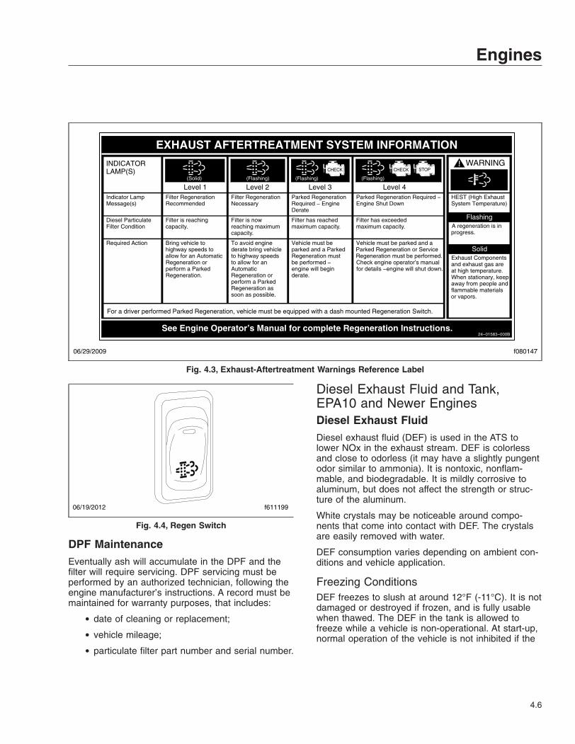
DPF MaintenanceEventually ash will accumulate in the DPF and thefilter will require servicing. DPF servicing must beperformed by an authorized technician, following theengine manufacturer’s instructions. A record must bemaintained for warranty purposes, that includes:
• date of cleaning or replacement;
• vehicle mileage;
• particulate filter part number and serial number.
Diesel Exhaust Fluid and Tank,EPA10 and Newer EnginesDiesel Exhaust FluidDiesel exhaust fluid (DEF) is used in the ATS tolower NOx in the exhaust stream. DEF is colorlessand close to odorless (it may have a slightly pungentodor similar to ammonia). It is nontoxic, nonflam-mable, and biodegradable. It is mildly corrosive toaluminum, but does not affect the strength or struc-ture of the aluminum.
White crystals may be noticeable around compo-nents that come into contact with DEF. The crystalsare easily removed with water.
DEF consumption varies depending on ambient con-ditions and vehicle application.
Freezing ConditionsDEF freezes to slush at around 12°F (-11°C). It is notdamaged or destroyed if frozen, and is fully usablewhen thawed. The DEF in the tank is allowed tofreeze while a vehicle is non-operational. At start-up,normal operation of the vehicle is not inhibited if the
f080147
EXHAUST AFTERTREATMENT SYSTEM INFORMATION
Switch.
Level 1 Level 3Level 2 Level 4Filter RegenerationRecommended
Filter is reaching
Bring vehicle tohighway speeds to
Filter RegenerationNecessary
Filter is nowreaching maximumcapacity.
To avoid enginederate bring vehicle
Parked RegenerationRequired − EngineDerate
Filter has reachedmaximum capacity.
Vehicle must beparked and a Parked
Parked Regeneration Required −Engine Shut Down
Filter has exceededmaximum capacity
Vehicle must be parked and aParked Regeneration or Service
(Solid) (Flashing) (Flashing)
CHECK CHECK
(Flashing)
INDICATORLAMP(S)
Indicator LampMessage(s)
Diesel ParticulateFilter Condition
Required Action
capacity. .
STOP
See Engine Operator’s Manual for complete Regeneration Instructions.
allow for an AutomaticRegeneration orperform a ParkedRegeneration.
to highway speedsto allow for anAutomaticRegeneration orperform a ParkedRegeneration assoon as possible.
Regeneration mustbe performed −engine will beginderate.
Regeneration must be performed.Check engine operator’s manualfor details −engine will shut down.
For a driver performed Parked Regeneration, vehicle must be equipped with a dash mounted Regeneration Switch.
06/29/2009
24−01583−000B
WARNING
HEST (High ExhaustSystem Temperature)
Exhaust Componentsand exhaust gas areat high temperature. When stationary, keepaway from people andflammable materialsor vapors.
A regeneration is inprogress.
Flashing
Solid
Fig. 4.3, Exhaust-Aftertreatment Warnings Reference Label
f61119906/19/2012
Fig. 4.4, Regen Switch
Engines
4.6
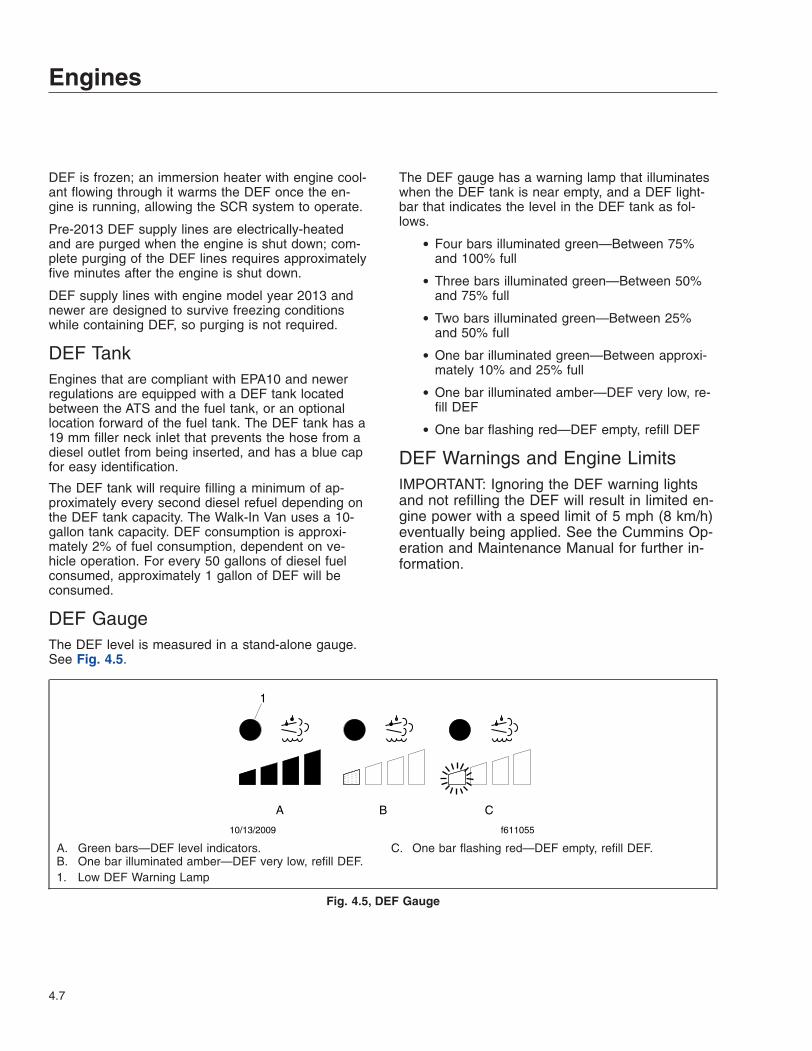
DEF is frozen; an immersion heater with engine cool-ant flowing through it warms the DEF once the en-gine is running, allowing the SCR system to operate.
Pre-2013 DEF supply lines are electrically-heatedand are purged when the engine is shut down; com-plete purging of the DEF lines requires approximatelyfive minutes after the engine is shut down.
DEF supply lines with engine model year 2013 andnewer are designed to survive freezing conditionswhile containing DEF, so purging is not required.
DEF TankEngines that are compliant with EPA10 and newerregulations are equipped with a DEF tank locatedbetween the ATS and the fuel tank, or an optionallocation forward of the fuel tank. The DEF tank has a19 mm filler neck inlet that prevents the hose from adiesel outlet from being inserted, and has a blue capfor easy identification.
The DEF tank will require filling a minimum of ap-proximately every second diesel refuel depending onthe DEF tank capacity. The Walk-In Van uses a 10-gallon tank capacity. DEF consumption is approxi-mately 2% of fuel consumption, dependent on ve-hicle operation. For every 50 gallons of diesel fuelconsumed, approximately 1 gallon of DEF will beconsumed.
DEF GaugeThe DEF level is measured in a stand-alone gauge.See Fig. 4.5.
The DEF gauge has a warning lamp that illuminateswhen the DEF tank is near empty, and a DEF light-bar that indicates the level in the DEF tank as fol-lows.
• Four bars illuminated green—Between 75%and 100% full
• Three bars illuminated green—Between 50%and 75% full
• Two bars illuminated green—Between 25%and 50% full
• One bar illuminated green—Between approxi-mately 10% and 25% full
• One bar illuminated amber—DEF very low, re-fill DEF
• One bar flashing red—DEF empty, refill DEF
DEF Warnings and Engine LimitsIMPORTANT: Ignoring the DEF warning lightsand not refilling the DEF will result in limited en-gine power with a speed limit of 5 mph (8 km/h)eventually being applied. See the Cummins Op-eration and Maintenance Manual for further in-formation.
A
1
B C
10/13/2009 f611055
A. Green bars—DEF level indicators.B. One bar illuminated amber—DEF very low, refill DEF.
C. One bar flashing red—DEF empty, refill DEF.
1. Low DEF Warning Lamp
Fig. 4.5, DEF Gauge
Engines
4.7

DEF Level Low—Initial and CriticalWarningsWhen the DEF level reads low the following warningsstrongly encourage the driver to refill the DEF tank.See Fig. 4.6.
• The DEF warning lamp illuminates constantly(initial warning).
• The DEF warning lamp flashes (critical warn-ing).
• DEF-level lightbar illuminates solid amber.
DEF EmptyWhen the DEF level reads empty, the following warn-ings are activated. See Fig. 4.7.
• One bar of the DEF-level lightbar flashes red.
• The DEF warning lamp flashes.
• The CHECK engine lamp illuminates.
Engine performance is limited, with progressivelyharsher engine power limits applied.
The DEF tank must be filled to cancel the warningsequence.
DEF Level Empty and IgnoredIf the empty warning is ignored and the DEF is notrefilled, the red STOP engine lamp illuminates in ad-dition to the DEF warning lamp and the CHECK en-gine warning lamp. See Fig. 4.8.
If the DEF tank is not refilled, a 5 mph (8 km/h)speed limit will be applied after the next engine shut-down, or while parked and idling.
DEF Quality or SCR Tampering
NOTICEOnce contaminated DEF has been detected in theSCR system, the vehicle must be taken to an au-thorized service center to check the SCR systemfor damage, and to deactivate the warning lightand engine limits.
If contaminated DEF or tampering is detected, theDEF warning light flashes, and engine performanceis limited with progressively harsher engine powerlimits applied. If the fault is not corrected, theCHECK engine lamp illuminates, then the STOP en-gine lamp illuminates and a 5 mph (8 km/h) speedlimit will be applied after the next engine shutdown,or while parked and idling. See Fig. 4.8.
A
B10/13/2009 f611056
A. DEF Warning Lamp (solid amber)B. DEF-Level Lightbar (1 bar solid amber)
Fig. 4.6, DEF Level Low Initial and Critical Warnings
10/13/2009 f611057
A
B
NOTE: Engine performance is limited.A. DEF Warning Lamp (flashing amber)B. DEF-Level Lightbar (1 bar flashing red)
Fig. 4.7, DEF Empty Warning
A
B11/18/2010 f611059bB
NOTE: The STOP engine, CHECK engine, and DEFlamps illuminate, engine power is limited, speed limit of5 mph (8 km/h).A. DEF Warning Lamp (flashing amber)B. DEF-Level Lightbar (1 bar flashing red)
Fig. 4.8, DEF Empty and Ignored Warning
Engines
4.8

Engine Shutdown
NOTICEExcept in an emergency, do not shut down theengine when the coolant temperature is above194°F (90°C). To do so could damage the engine.
1. With the vehicle stopped, place the transmissionin the neutral (N) position and set the parkingbrake.
2. It is important to idle an engine for 3 to 5 min-utes before shutting it down. This allows the lu-bricating oil and the coolant to carry heat awayfrom the combustion chambers, bearings, shafts,and seals.
IMPORTANT: Long periods of idling are notgood for an engine because the combustionchamber temperatures drop so low that the fuelmay not burn completely. This will cause carbonto clog the piston rings and may result in stuckvalves.
3. Do not idle the engine for excessively long peri-ods.
4. Turn the ignition key to the OFF position andshut down the engine.
Engines
4.9

5
TransmissionsAllison Automatic Transmissions . . . . . . . . . . . . . . . . . . . . . . . . . . . . . . . . . . . . . . . . . . . . . . . . . . . . . 5.1

Allison AutomaticTransmissionsGeneral InformationAllison four- and five-speed automatic transmissionshave six or seven shift positions on the selectorlever. The selector lever is lighted for night driving.Each forward shift position provides a range of for-ward gears that are selected automatically accordingto the speed of the vehicle, engine temperature, andthrottle position. The 1000 Series, 2000 Series, and2500 Series are fully automatic transmissions. Seethe Allison website for additional information, atwww.allisontransmission.com.
Driving PrecautionsThe vehicle operator should use care when acceler-ating or downshifting on slippery road surfaces. Sud-den acceleration or engine braking, caused by shift-ing to a lower gear range, can result in a loss ofvehicle control. This is very important on snow- orice-covered roads. See Chapter 7 for information onbrake operation.
If the vehicle is stuck in sand or mud, do not attemptto pull the vehicle out under its own power. Requestprofessional towing assistance.
NOTICEDo not attempt to rock the vehicle. If rocking thevehicle is necessary, even at low speeds, it maycause engine overheating, axle damage, trans-mission damage or failure, or tire damage.
Do not coast the vehicle in neutral. Severe trans-mission damage may result and the vehicle willnot have the benefit of engine braking.
WARNINGTo reduce the risk of personal injury, beforegoing down a steep or long grade, reduce speedand downshift the transmission. Do not hold thebrake pedal down too long or too often whilegoing down a steep or long grade. This couldcause the brakes to overheat, reducing their ef-fectiveness. As a result, the vehicle will not slowdown at the usual rate. Failure to take thesesteps could result in loss of vehicle control.
To avoid skidding on slippery roads, do not downshiftinto "1" (Low) at speeds above 20 mph (32 km/h).
On slippery surfaces, avoid quick movements of thesteering wheel. Decrease your speed and allow forextra stopping distance required by these conditions.
Avoid driving through flooded areas unless you aresure the water is no higher than the bottom of thewheel rims. Drive through slowly. Allow adequatestopping distance since wet brakes do not grip well.After driving through water, gently apply the brakesseveral times while the vehicle is moving slowly todry the brakes.
When driving on icy or graveled surfaces, reducespeed. Avoid sharp turning maneuvers.
Series 1000, 2000, and 2500Transmission Operation
WARNINGDo not leave the vehicle unattended with the en-gine running. If you leave the vehicle and the en-gine is running, the vehicle can move suddenly,which could result in personal injury or propertydamage.
1000 SeriesOn vehicles with Allison 1000 series transmissions,do the following steps if you have to leave the cabwith the engine running (for example, when checkingthe transmission fluid):
Without Park (P) Position1. Bring the vehicle to a complete stop using the
service brake.
2. Ensure that the engine is at low idle rpm.
3. Put the transmission in Neutral (N).
4. Apply the parking brake, and make sure it isproperly engaged.
5. Chock the rear tires and take any other stepsnecessary to keep the vehicle from moving.
With Park (P) Position1. Bring the vehicle to a complete stop using the
service brake.
2. Ensure that the engine is at low idle rpm.
Transmissions
5.1

3. Put the transmission in Park (P).
4. Apply the parking brake and make sure that it isproperly engaged.
5. Engage the Park (P) range by slowly releasingthe service brake.
6. Chock the rear tires and take any other stepsnecessary to keep the vehicle from moving.
2000 SeriesOn vehicles with Allison 2000 series transmissions,do the following steps if you have to leave the cabwith the engine running (for example, when checkingthe transmission fluid):
Without Auto-Apply Parking Brake (PB)Follow the instructions for vehicles with 1000 seriestransmissions, under the heading "Without Park (P)Position."
With Auto-Apply Parking Brake (PB)1. Bring the vehicle to a complete stop using the
service brake.
2. Ensure that the engine is at low idle rpm.
3. Put the transmission in Auto-Apply Parking Brake(PB).
4. Ensure that the parking brake is properly en-gaged.
5. Chock the rear tires and take any other stepsnecessary to keep the vehicle from moving.
2500 SeriesOn vehicles with 2500 series transmissions, instruc-tions are as follows.
1. Bring the vehicle to a complete stop using theservice brake.
2. Ensure that the engine is at low idle rpm.
3. Put the transmission in Park (P).
4. Apply the parking brake and make sure that it isproperly engaged.
5. Engage the Park (P) range by slowly releasingthe service brake.
6. Chock the rear tires and take any other stepsnecessary to keep the vehicle from moving.
Range Inhibit Indicator, 2000 SeriesA RANGE INHIBIT indicator is a standard feature ofthe 2000 series transmissions. The RANGE INHIBITindicator comes on to alert the driver that transmis-sion operation is being inhibited and that the rangeshifts being requested by the driver may not occur.When certain operating conditions are detected bythe TCM (transmission control module), the controlswill lock the transmission in the current operatingrange.
Shift inhibits occur under the following conditions:
• Shifts from Neutral (N) to Reverse (R) or fromNeutral (N) to a forward range when the en-gine is above idle, greater than 900 rpm.
• Forward/Reverse (R) directional shifts are typi-cally not permitted if appreciable output shaftspeed is detected.
• When some types of unusual transmission op-erating conditions are detected by the TCM,the TCM temporarily limits transmission opera-tion until the vehicle can be driven to a servicelocation. When this type of situation is de-tected, the TCM will lock the transmission in asafe gear range.
Operating Instructions, On-HighwayTransmissionsAllison 1000/2000/2500 automatic transmissions areelectronically controlled and provide five or six for-ward ranges and one Reverse (R) range. Typically, aT-handle shift control is used by the driver to selectthe ranges. See Fig. 5.1 and Fig. 5.2.
Park (P) [optional on 1000 and 2500Series]Use Park (P) when starting or shutting down the en-gine, to check vehicle accessories, and to operatethe engine in idle for longer than 5 minutes. This po-sition places the transmission in Neutral (N) and en-gages the park pawl.
Auto-Apply Parking Brake (PB) [optionalon 2000 Series]The Auto-Apply Parking Brake (PB) places the ve-hicle in Neutral (N) and applies the parking brake.
Transmissions
5.2

Reverse (R)Reverse (R) is used to back the vehicle. When theselector is in Reverse (R), the reverse warning signalwill sound. Always bring the vehicle to a completestop before shifting from a forward range to Reverse(R), or from Reverse (R) to a forward range.
NOTICEExtended idling in Reverse (R) may cause trans-mission overheating and damage.
Do not idle in Reverse (R) for more than 5 minutes.Select Park (P), Auto-Apply Parking Brake (PB), orNeutral (N) when time at idle exceeds 5 minutes.
NOTE: The shift into Reverse (R) may not suc-ceed if a range inhibitor is active. Check for illu-mination of the RANGE INHIBIT indicator.
Neutral (N)The Neutral (N) position places the transmission inNeutral (N). This position is used when starting theengine and for stationary operation.
WARNINGFailure to apply the vehicle parking brakes whenthe transmission is in neutral may allow the ve-hicle to move unexpectedly, possibly causingproperty damage or personal injury.
When Neutral (N) is selected, the vehicle servicebrakes, or parking brake must be applied. SelectingNeutral (N) does not apply vehicle brakes unless anauxiliary system to apply the parking brake is in-stalled.
WARNINGDo not coast in neutral. Coasting in neutral cancause an accident, possibly resulting in severepersonal injury or death.
Do not let the vehicle coast in Neutral (N). If the ve-hicle is allowed to coast in Neutral (N), you couldlose control of the vehicle.
1
P
R
N
3
D
4
09/12/2006 f261381
Fig. 5.1, T-Handle Shift Control (typical shifter)
07/23/2014 f611243
Fig. 5.2, T-Handle Shift Control (optional shifter)
Transmissions
5.3

NOTICECoasting in Neutral (N) can cause severe trans-mission damage.
Drive (D)
WARNINGWhen going downhill, use a combination ofdownshifting, braking, and other retarding de-vices to control vehicle speed and the engine’srated governed speed. Failure to do so could re-duce vehicle braking, possibly causing loss ofvehicle control and resulting in personal injury orproperty damage.
In the Drive (D) position, the transmission will initiallygo into First (1) range when Drive (D) is selected. Asvehicle speed increases, the transmission will upshiftautomatically through each available range up toFourth (4) range or Fifth (5) range. As the vehicleslows, the transmission will downshift automatically.
When going downhill, downshift to a lower transmis-sion range to increase engine braking and to helpmaintain control. The transmission has a feature toprevent automatic upshifting above the lower rangeselected. However, during downhill operation, thetransmission may upshift to the next higher range, ifthe engine is exceeding its governed speed in thelower range.
NOTICEDo not idle in Drive (D) for more than 5 minutes.Extended idling in Drive (D) may cause transmis-sion overheating and damage. Always selectAuto-Apply Parking Brake (PB) or Park (P) if timeat idle is longer than 5 minutes.
NOTE: The shift into Drive (D) may not succeedif a range inhibitor is active. Check for illumina-tion of the RANGE INHIBIT indicator.
Fourth and Third Ranges (4 and 3)[optional]Use the Fourth (4) or Third (3) range for city trafficand for braking on steep downgrades.
Third and Second Ranges (3 and 2)[standard]Use the Third (3) or Second (2) range for heavy citytraffic and for braking on steeper downgrades.
First Range (1)Use First (1) range when pulling through mud ordeep snow, when maneuvering in tight spaces, orwhen driving up or down very steep grades. First (1)range provides the vehicle with its maximum drivingtorque and maximum engine braking effect.
Transmissions
5.4

6
Steering SystemSteering General Information . . . . . . . . . . . . . . . . . . . . . . . . . . . . . . . . . . . . . . . . . . . . . . . . . . . . . . . . 6.1Power Steering System . . . . . . . . . . . . . . . . . . . . . . . . . . . . . . . . . . . . . . . . . . . . . . . . . . . . . . . . . . . . 6.1Tilt/Telescope Steering Column . . . . . . . . . . . . . . . . . . . . . . . . . . . . . . . . . . . . . . . . . . . . . . . . . . . . . 6.1

Steering General InformationWhen there is no load on the vehicle and the fronttires are pointed straight ahead, the steering wheelspokes should be at the 9 o’clock and 3 o’clock posi-tions, or within 10 degrees to either side. SeeFig. 6.1. See Group 46 of the Walk-In Van ChassisWorkshop Manualfor steering adjustment procedures.
Power Steering SystemThe power steering system consists of a steeringgear (which includes a manual steering mechanism,a hydraulic control valve, and a hydraulic power cyl-inder), hydraulic hoses, power steering pump, reser-voir, and other components. The power steeringpump, driven by the engine, provides the power as-sist for the steering system. If the engine is not run-ning, there is no power assist.
If the power-assist feature does not work due to hy-draulic fluid loss, steering pump damage, or someother cause, bring the vehicle to a safe stop. Do notdrive the vehicle until the cause of the problem hasbeen corrected.
WARNINGDriving the vehicle without the power-assist fea-ture of the steering system requires much greatereffort, especially in sharp turns or at low speeds,which could result in an accident and possibleinjury.
Drivers should use the power available with a powersteering system carefully. If the front tires becomelodged in a deep chuckhole or rut, drive the vehicleout instead of using the steering system to lift thetires from the hole. Also avoid turning the tires whenthey are against a curb as this places a heavy loadon steering components and could damage them.
Tilt/Telescope Steering ColumnLever Adjustment (optional)To change the position of the steering wheel, pull thelever upward and move the steering wheel to the de-sired position. See Fig. 6.2. Release the lever to lockthe position. The steering wheel can also be tilted upto provide easier exit and reentry.
If the chassis is equipped with a telescoping steeringcolumn, push the lever down and extend or retractthe steering wheel as desired.
WARNINGMake sure that the control lever is in the locked(neutral) position before driving the vehicle.Never tilt the column while driving the vehicle.Doing so could cause loss of vehicle control andresult in personal injury and property damage.
f461923 11/14/2001
1 2
10°
10° 10°
10°
1. 9 o’Clock 2. 3 o’Clock
Fig. 6.1, Steering Wheel Centered
10/12/2007 f462115
1
1. Tilt/Telescope Lever
Fig. 6.2, Tilt/Telescope Steering Column with LeverAdjustment
Steering System
6.1

Foot Pedal Adjustment (optional)If the tilt/telescope steering column is equipped witha foot pedal adjustment, depress the foot pedal tomove the steering column to the desired position.Release the foot pedal to lock the position. SeeFig. 6.3.
WARNINGMake sure that the steering column is locked be-fore driving the vehicle. Never tilt or telescopethe steering wheel while driving the vehicle.Doing so could cause loss of vehicle control,personal injury, and property damage.
f462016
1
05/11/2005
1. Tilt/Telescope Foot Pedal
Fig. 6.3, Tilt/Telescope Steering Column with FootPedal Adjustment
Steering System
6.2

7
Hydraulic and Air BrakeSystems
Hydraulic Brake System . . . . . . . . . . . . . . . . . . . . . . . . . . . . . . . . . . . . . . . . . . . . . . . . . . . . . . . . . . . . 7.1Air Brake System . . . . . . . . . . . . . . . . . . . . . . . . . . . . . . . . . . . . . . . . . . . . . . . . . . . . . . . . . . . . . . . . . 7.2

Hydraulic Brake SystemGeneral InformationThe hydraulic brake system includes a powerbooster, master cylinder, reservoir, hydraulic brakelines, a brake rotor on each wheel hub, and a brakecaliper and pad assembly at each rotor. See Fig. 7.1.
IMPORTANT: Make sure that the fluid in themaster cylinder reservoirs is up to the level ofthe ridge that surrounds the reservoir. Use onlyheavy-duty brake fluid, DOT 3, in the hydraulicbrake system.
The master cylinder controls braking power to thefront and rear brakes. The Bendix Hydro-Max®power booster is attached to the rear of the mastercylinder and is connected to the power steering sys-tem (which provides pressurized power steeringfluid). An electrically powered "reserve" pump oper-ates if there is inadequate fluid flow from the powersteering pump to the power booster. The brake sys-tem warning light comes on if there is a problemwithin the system. Bring the vehicle to a safe stopand correct the problem before continuing operationof the vehicle. See Group 42 of the Walk-In VanChassis Workshop Manual for hydraulic brake sys-tem troubleshooting and adjustment procedures.
OperationBefore driving the vehicle, secure all loose items inthe cab so that they will not fly forward during a fullbrake application. Check that the brake system warn-ing light is off after releasing the hand brake. If thewarning light does not go off, correct the problembefore continuing operation of the vehicle.
During normal braking stops, depress the foot brakecontrol pedal until braking action slows down the ve-hicle. Increase or decrease the pressure on thepedal so that the vehicle comes to a smooth, safestop. When the forward speed of the vehicle has de-creased to almost the idling speed of the engine,push the clutch pedal in (if equipped) and shift thetransmission into Neutral (N). Apply the hand parkingbrake if the vehicle is to be parked.
Meritor WABCO® Antilock BrakingSystem (ABS)The Meritor WABCO® Antilock Braking System(ABS) is an electronic wheel speed monitoring andcontrol system that works with the hydraulic brakesystem. ABS passively monitors vehicle wheel speedat all times, but controlswheel speed during an emer-gency or reduced-traction stop. In normal brakingapplications, the standard hydraulic brake system isin effect.
IMPORTANT: For proper ABS system operation,the front and rear tires must rotate at speedswithin 16% of one another. Installing differentsized tires on just the front or rear axle will re-sult in inaccurate wheel speed signals to theECU resulting in a reduced braking force, whichcould lead to longer stopping distances.
ABS includes signal-generating tone wheels and sen-sors located in the wheel hubs of each sensed axle.The sensors transmit vehicle wheel speed informa-tion to an electronic control unit (located on theframe rail) that interprets these signals to calculatewheel speed and a vehicle reference speed. If thecalculations indicate wheel lockup, the appropriatecontrol circuit signals the brake pressure modulatorto increase or decrease braking pressure until wheelslip has been corrected.
The electronic control unit also has a safety circuitthat constantly monitors the wheel sensors, brakepressure modulator, and the electrical circuitry. Thedash warning light (ABS) comes on after the ignition
04/26/2012 f460513a
A
B
A. Open caps and check fluid level.B. Fill to this level.
Fig. 7.1, Hydraulic Brake Reservoir (MT-45 and MT-55)
Hydraulic and Air Brake Systems
7.1

is switched to the ON position. Once the vehiclemoves faster than about 4 mph (6 km/h), the warninglight goes out only if all of the vehicle’s ABS compo-nents are working properly.
If during vehicle operation, the safety circuit senses afailure in any part of the ABS system (a sensor,brake pressure modulator, wiring connection, shortcircuit, etc.), the warning light (ABS) comes on andthe control circuit where the failure occurred isswitched to normal braking action. Even if the ABSsystem is partially or completely inoperative, normalbraking ability is maintained. An exception would beif the brake pressure modulator or hydraulic fluid lineis damaged. Since these components are an integralpart of the hydraulic brake system, normal brakingmay be impaired or inoperative.
IMPORTANT: If the ABS warning light does notwork as described above or comes on whiledriving, repair the ABS system immediately toensure full antilock braking capability.
See the diagnostic menu screens in Chapter 2, andfollow the steps to read the fault codes in the instru-ment panel diagnostic menu.
During emergency or reduced-traction stops, fullydepress the brake pedal until the vehicle comes to asafe stop; do not pump the brake pedal. With thebrake pedal fully depressed, the ABS system willcontrol all wheels to provide steering control and areduced braking distance.
WARNINGAlthough the ABS system improves vehicle con-trol during emergency braking situations, thedriver still has the responsibility to change driv-ing styles depending on existing traffic and roadconditions. Failure to change driving styles toaccomodate existing traffic and road conditionscould cause an accident, possibly resulting inpersonal injury or death, or property damage.
Air Brake SystemGeneral InformationA dual air brake system consists of two independentair brake systems that use a single set of brake con-trols. Each system has its own reservoir, plumbing,and brake chambers. The primary system operates
the service brakes on the rear axle; the secondarysystem operates the service brakes on the front axle.
WARNINGDo not operate the vehicle with the front brakesbacked off or disconnected. Backing off or dis-connecting the front brakes will not improve ve-hicle handling and may lead to loss of vehiclecontrol resulting in property damage or personalinjury.
Before driving your vehicle, allow time for the aircompressor to build up a minimum of 95 psi (655kPa) pressure in both the primary and the secondarysystems. Monitor the air pressure system by observ-ing the dual system air pressure gauges and the lowair-pressure warning light and buzzer. The warninglight and buzzer shut off when the pressure in bothsystems reaches 65 to 73 psi (448 to 503 kPa).
The warning light and buzzer comes on if air pres-sure drops below 65 to 73 psi (448 to 503 kPa) ineither system. If this happens, check the air systempressure gauges to determine which system has lowair pressure. Although the vehicle’s speed can bereduced using the foot brake control pedal, either thefront or the rear service brakes will not be operating,causing a longer stopping distance. Bring the vehicleto a safe stop and have the air system repaired be-fore continuing.
The parking brake will apply when air pressure dropsbelow 38 to 42 psi (262 to 290 kPa). Do not wait forthe brake to apply automatically; when the warninglight and buzzer first come on, immediately bring thevehicle to a safe stop. Before continuing operation ofthe vehicle, correct the cause of the air loss.
Air Brake System With External Fill(Shrader) ValveIf your engine will not start and it is desirable to re-lease the parking brake, do the following: Block thewheels. Turn the ignition switch to the ON position.Fill the air reservoir for the braking system by exter-nal means. The parking brake will not release untilair pressure reaches 65 psi (448 kPa). The low airbuzzer will sound until air pressure reaches 65 psi(448 kPa) with the ignition switch in the ON position.
IMPORTANT: If the air pressure in the brakingsystem drops back below 38 to 42 psi (262 to290 kPa) the parking brake will reengage.
Hydraulic and Air Brake Systems
7.2

OperationBefore driving the vehicle, secure all loose items inthe cab so that they will not fly forward during a fullbrake application. Make sure that all occupants arewearing seat belts.
During normal braking stops, depress the foot brakecontrol pedal until braking action slows down the ve-hicle. Increase or decrease the pressure on thepedal so that the vehicle comes to a smooth, safestop. When the forward speed of the vehicle has de-creased to almost the idling speed of the engine,push the clutch pedal in (if equipped) and shift thetransmission into Neutral (N). Apply the hand parkingbrake if the vehicle is to be parked.
IMPORTANT: In the event of a total loss of ser-vice brakes with full system air pressure, usethe parking brake control valve (yellow knob) tobring the vehicle to a complete stop in the saf-est location possible.
The yellow diamond-shaped knob on the controlpanel actuates the parking brake valve. Pull out theknob to apply the parking brake. See Fig. 7.2.
WARNINGIf the vehicle is equipped with an air suspensionsystem, do not move the vehicle with the air sus-pension deflated. Doing so could result in a lossof vehicle control, possibly causing personal in-jury and property damage.
NOTICEDo not use the spring brakes if the servicebrakes are hot, such as after descending a steepgrade. Also, do not use the spring parking brakesduring freezing temperatures if the servicebrakes are wet. To do so could damage the
brakes if hot, or cause them to freeze during coldweather.
If the brakes are wet, drive the vehicle in Low (L) orFirst (1) gear and lightly apply the brakes to heat anddry them.
Allow hot brakes to cool before using the parkingbrake. Always chock the tires.
Automatic Slack AdjustersAutomatic slack adjusters are required on all vehiclesequipped with air brakes manufactured after October20, 1994. Automatic slack adjusters should never bemanually adjusted except during routine maintenanceof the foundation brakes (e.g., replacing shoes), dur-ing slack adjuster installation, or in an emergencysituation.
When the brake pushrod stroke exceeds the legalbrake adjustment limit on a vehicle, there is likely amechanical problem with the foundation brake com-ponents or the adjuster is improperly installed.
Visit a repair facility as soon as possible whenbrakes equipped with automatic slack adjusters aredetermined to be out of adjustment.
NOTICEManually adjusting an automatic slack adjuster tobring the pushrod stroke within legal limits islikely masking a mechanical problem. Adjustmentis not repairing. In fact, continual adjustment ofautomatic slack adjusters may result in prema-ture wear of the adjuster itself. Further, the im-proper adjustment of some automatic slack ad-justers may cause internal damage to theadjuster, thereby preventing it from properlyfunctioning.
03/30/2010 f421624
Fig. 7.2, Parking Brake Control Knob
Hydraulic and Air Brake Systems
7.3

8
Compressed Natural GasFuel System
CNG General Information . . . . . . . . . . . . . . . . . . . . . . . . . . . . . . . . . . . . . . . . . . . . . . . . . . . . . . . . . . 8.1CNG Fuel Tank Filling Procedure . . . . . . . . . . . . . . . . . . . . . . . . . . . . . . . . . . . . . . . . . . . . . . . . . . . . 8.1Engine Starting . . . . . . . . . . . . . . . . . . . . . . . . . . . . . . . . . . . . . . . . . . . . . . . . . . . . . . . . . . . . . . . . . . . 8.2CNG Safety Precautions . . . . . . . . . . . . . . . . . . . . . . . . . . . . . . . . . . . . . . . . . . . . . . . . . . . . . . . . . . . 8.3

CNG General InformationNatural gas is a mixture of hydrocarbon gasses witha high concentration of methane gas, which burnscompletely into carbon dioxide and water, resulting inlower emissions than with diesel or gasoline.
Natural gas is less energy dense than diesel, there-fore, a larger volume of natural gas is required toproduce the same power. This is one reason for theslightly lower maximum power in natural-gas-powered vehicles. The power difference is a reduc-tion in maximum power only and does not affect nor-mal driving. The power reduction is evidenced only inwide-open throttle, high-torque conditions.
IMPORTANT: The natural gas fuel systemshould be routinely inspected for gas leakage.Use a natural gas detector to check the fueltanks, fuel filtering and regulating mechanisms,and the fuel lines. If necessary, replace leakingfuel tanks; repair or replace any lines, devices,or connections that are leaking.
Natural gas is nontoxic, but it can cause asphyxiationin certain circumstances. Commercial compressednatural gas normally contains an odor-producingchemical, which enables users to detect gas leaks,but a natural gas detector is recommended forchecking for leaks.
A typical natural gas fuel system consists of:
• Fuel supply containers or tanks storing the gasat high pressure.
• A pressure relief valve and manual shutoffvalves.
• A filling connection with a check valve to pre-vent the gas from flowing back out of the con-nection.
• A valve that automatically closes if the enginestops.
• A high-pressure fuel filter and a low-pressurefuel filter.
• A pressure regulator to reduce the fuel tankpressure to the lower pressure needed for theengine.
• A gas-air mixer to produce a flammable mix-ture for the engine.
• A pressure gauge to indicate the fuel supply inthe tanks.
CNG Fuel Tank FillingProcedureCNG is moved from the fuel station storage tanks tothe vehicle cylinders through a metered dispenser.During fueling, as pressure inside of the vehicle cyl-inders increases, so does the temperature. The dis-penser shuts off when it determines the CNG cylin-ders are full.
CNG fuel cylinders cannot be filled to their full capac-ity of 3600 psi (24 821 kPa) in cooler weather. Sincetemperature change causes gas to expand and con-tract, less pressure in the cylinders on a cold day isequal to the same amount of gas at a higher pres-sure on a warm day. The fuel station dispenser has atemperature-pressure compensating device, whichaccounts for ambient temperature during fueling. SeeTable 8.1 for approximate full cylinder pressures atvarious temperatures.
CNG Temperature/Pressure Compensation Values
Temperature:°F (°C)
Fill Station Pressure Set Point3000 psi (20 684kPa) Set Point
3600 psi (24 821kPa) Set Point
100 (37.8) 3415 (23 546) 4086 (28 172)90 (32.2) 3276 (22 587) 3909 (26 952)80 (26.7) 3138 (21 636) 3754 (25 883)70 (21.1) 3000 (20 684) 3600 (24 821)60 (15.6) 2861 (19 726) 3445 (23 752)50 (10) 2723 (18 774) 3288 (22 670)40 (4.4) 2584 (17 816) 3131 (21 587)30 (-1.1) 2446 (16 865) 2973 (20 498)20 (-6.7) 2307 (15 906) 2814 (19 402)
10 (-12.2) 2169 (14 955) 2655 (18 306)0 (-17.8) 2031 (14 003) 2495 (17 202)
-10 (-23.3) 1893 (13 052) 2336 (16 106)-20 (-28.9) 1755 (12 100) 2180 (15 031)-30 (34.4) 1616 (11 142) 2024 (13 955)-40 (-40) 1477 (10 184) 1868 (12 879)
Table 8.1, CNG Temperature/Pressure CompensationValues
Use the following steps to fuel a CNG vehicle.
1. Shut down the engine and apply the parkingbrake.
Compressed Natural Gas Fuel System
8.1

IMPORTANT: Close all windows and doors dur-ing the fueling process. Keeping windows anddoors closed allows for easier leak detectioninside the cab after fueling.
WARNINGNatural gas fuel tanks, lines, and valves are al-ways pressurized. Always observe safety precau-tions. Failure to do so could lead to loss of con-trol over a filling hose or to ignition of the naturalgas, which could cause serious bodily injury,death, or severe property damage.
2. Ensure all fuel cylinder shutoff valves are open.
3. Ensure the vehicle fuel system main shutoffvalve is open.
4. Open the CNG fuel panel access door and re-move the dust cap from the vehicle fuel fill port.
5. Ensure the O-ring is present inside the fuel fillport. If the O-ring has been dislodged or is miss-ing, the station dispensing nozzle will not con-nect securely to the fill port.
6. Turn the selector knob on the service pump tothe VENT position, if equipped.
7. Connect the quick coupling on the dispensingnozzle securely to the vehicle fuel fill port.
8. Turn the selector knob on the service pump tothe FILL position, if equipped.
IMPORTANT: If at any time the service pump orvehicle begins to vent CNG uncontrollably, notifya station attendant or activate the service sta-tion emergency shut-off switch to cease the flowof CNG.
9. Switch on the service pump. A slight hissingnoise may be heard as the fuel cylinders fill.
10. Watch the pressure gauge on the service pump.When the gauge reads approximately 3600 psi(24 821 kPa), or when the fill pressure stopsclimbing, the CNG cylinders are full. The servicepump will shut itself down automatically. SeeTable 8.1 for pressure compensation valuesbased on ambient temperatures.
11. Move the selector knob on the service pump tothe VENT position, if equipped. A short hiss will
be heard as a small amount of natural gas isvented into the hose.
WARNINGDo not attempt to remove the fill station nozzlefrom the tank fill fitting until venting of pressureis noted. If no venting occurs, ask for assistancefrom the station attendant. Removing an un-vented coupling could result in an uncontrolledhose, which could lead to property damage orpersonal injury.
12. Remove the station dispensing nozzle from thevehicle fill port.
13. Install the dust cap on the vehicle fuel fill portand close the fuel panel access door.
Engine Starting1. Set the parking brake.
2. Move the fuel shut-off valve handle to the RUNposition.
NOTICEProtect the turbocharger during engine start-upby not opening the throttle or accelerating theengine above 1000 rpm until normal engine idleoil pressure registers on the gauge.
3. For automatic transmissions, make sure that thetransmission shift control is in Neutral (N), Park(P), or the Park Brake (PB) position.
4. Turn the ignition switch to the START position.See Fig. 8.1 for the four-position ignition switchand Fig. 8.2 for the three-position ignition switch.After the engine starts, release the key.
NOTICEDo not crank the engine for more than 30 sec-onds at a time during any of the following proce-dures. Wait two minutes after each try to allowthe starter to cool. Failure to do so could causestarter damage.
5. Bring the engine up to operating speed graduallyas it warms up and develops stable oil pressure.
Compressed Natural Gas Fuel System
8.2

IMPORTANT: When the engine is started, ittakes a short time to build up a lubricating oilfilm between the shafts and bearings, and be-tween the pistons and cylinder walls. The oilpressure gauge indicates any drop in lubricatingoil pressure within 15 seconds of engine startup.See the Cummins Operation and MaintenanceManual for minimum idle oil pressure specifica-tions.
CNG Safety Precautions
DANGERNatural gas is highly flammable. Failure to ob-serve the following safety precautions could leadto the ignition of the natural gas, which couldcause serious bodily injury or death.
CNG General Safety InformationSince compressed natural gas is highly flammable, ifyou should smell gas, immediately shut off all en-gines and ignition sources. Avoid causing sparks,and stay away from arcing switches and equipment.Extinguish any cigarettes, pilot lights, flames, or othersources of ignition in the area and adjacent areas.Immediately provide extra ventilation to the area. Donot start the engine or any other type of equipmentuntil the gas leak is corrected and the area clearedof natural gas.
Natural gas is odorless before a scent is added forsafety. Natural gas is also colorless and nontoxic.Still, at high enough concentration, natural gas cansuffocate a person simply by excluding adequateoxygen to sustain life.
Natural gas is flammable in concentrations rangingfrom 4 percent to 16 percent by volume in air.
WARNINGWhen bleeding the dispensing hose after fillingthe tank, the handle gets extremely cold. Thismay freeze the hands if appropriate safety glovesare not used.
When filling the vehicle tanks with compressed natu-ral gas (CNG), vent the dispensing hose before dis-connecting it from the vehicle. The pressure in thehose may cause a disconnected hose to become un-controllable.
CNG storage tanks have a limited usable life-span,due to the high pressures that they must sustain. Pe-riodic inspections are required by law to ensure con-tinued safety in their use.
If a tank receives an impact or has deep scratches orgouges, it should be inspected before refilling.
07/10/96
1
2
34
f601179
1. Accessory (optional)2. Off
3. On4. Start
Fig. 8.1, Four-Position Ignition Switch
05/10/2001
1
23
f601179a
1. Off 2. On 3. Start
Fig. 8.2, Three-Position Ignition Switch
Compressed Natural Gas Fuel System
8.3
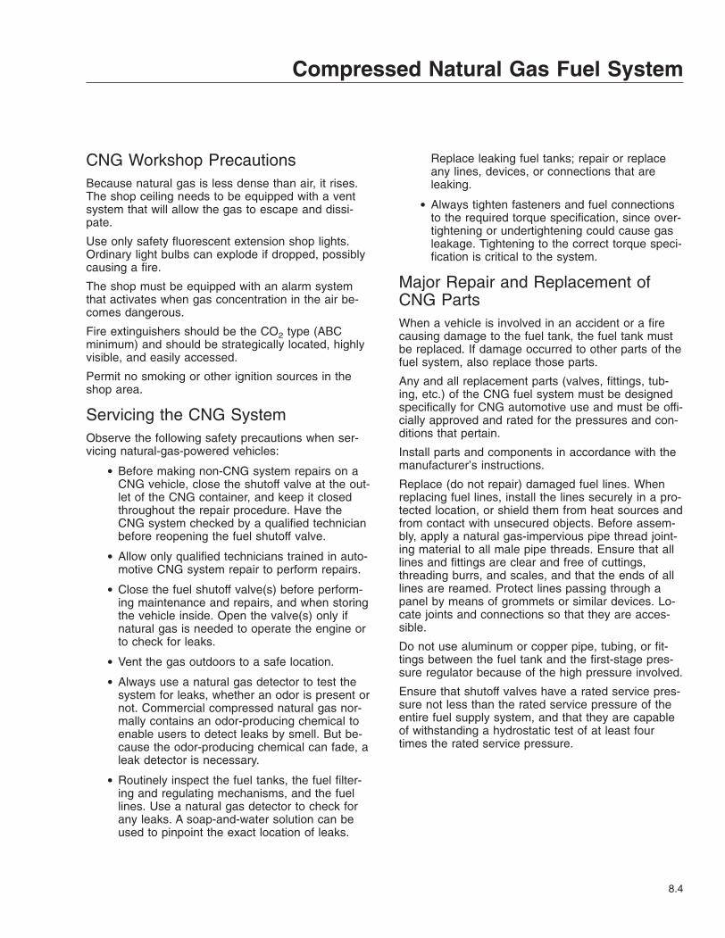
CNG Workshop PrecautionsBecause natural gas is less dense than air, it rises.The shop ceiling needs to be equipped with a ventsystem that will allow the gas to escape and dissi-pate.
Use only safety fluorescent extension shop lights.Ordinary light bulbs can explode if dropped, possiblycausing a fire.
The shop must be equipped with an alarm systemthat activates when gas concentration in the air be-comes dangerous.
Fire extinguishers should be the CO2 type (ABCminimum) and should be strategically located, highlyvisible, and easily accessed.
Permit no smoking or other ignition sources in theshop area.
Servicing the CNG SystemObserve the following safety precautions when ser-vicing natural-gas-powered vehicles:
• Before making non-CNG system repairs on aCNG vehicle, close the shutoff valve at the out-let of the CNG container, and keep it closedthroughout the repair procedure. Have theCNG system checked by a qualified technicianbefore reopening the fuel shutoff valve.
• Allow only qualified technicians trained in auto-motive CNG system repair to perform repairs.
• Close the fuel shutoff valve(s) before perform-ing maintenance and repairs, and when storingthe vehicle inside. Open the valve(s) only ifnatural gas is needed to operate the engine orto check for leaks.
• Vent the gas outdoors to a safe location.
• Always use a natural gas detector to test thesystem for leaks, whether an odor is present ornot. Commercial compressed natural gas nor-mally contains an odor-producing chemical toenable users to detect leaks by smell. But be-cause the odor-producing chemical can fade, aleak detector is necessary.
• Routinely inspect the fuel tanks, the fuel filter-ing and regulating mechanisms, and the fuellines. Use a natural gas detector to check forany leaks. A soap-and-water solution can beused to pinpoint the exact location of leaks.
Replace leaking fuel tanks; repair or replaceany lines, devices, or connections that areleaking.
• Always tighten fasteners and fuel connectionsto the required torque specification, since over-tightening or undertightening could cause gasleakage. Tightening to the correct torque speci-fication is critical to the system.
Major Repair and Replacement ofCNG PartsWhen a vehicle is involved in an accident or a firecausing damage to the fuel tank, the fuel tank mustbe replaced. If damage occurred to other parts of thefuel system, also replace those parts.
Any and all replacement parts (valves, fittings, tub-ing, etc.) of the CNG fuel system must be designedspecifically for CNG automotive use and must be offi-cially approved and rated for the pressures and con-ditions that pertain.
Install parts and components in accordance with themanufacturer’s instructions.
Replace (do not repair) damaged fuel lines. Whenreplacing fuel lines, install the lines securely in a pro-tected location, or shield them from heat sources andfrom contact with unsecured objects. Before assem-bly, apply a natural gas-impervious pipe thread joint-ing material to all male pipe threads. Ensure that alllines and fittings are clear and free of cuttings,threading burrs, and scales, and that the ends of alllines are reamed. Protect lines passing through apanel by means of grommets or similar devices. Lo-cate joints and connections so that they are acces-sible.
Do not use aluminum or copper pipe, tubing, or fit-tings between the fuel tank and the first-stage pres-sure regulator because of the high pressure involved.
Ensure that shutoff valves have a rated service pres-sure not less than the rated service pressure of theentire fuel supply system, and that they are capableof withstanding a hydrostatic test of at least fourtimes the rated service pressure.
Compressed Natural Gas Fuel System
8.4

9
Hybrid Electric VehicleSafety Precautions . . . . . . . . . . . . . . . . . . . . . . . . . . . . . . . . . . . . . . . . . . . . . . . . . . . . . . . . . . . . . . . . 9.1Foot Pedal-Operated Parking Brake . . . . . . . . . . . . . . . . . . . . . . . . . . . . . . . . . . . . . . . . . . . . . . . . . . 9.1Engine Starting and Shutdown . . . . . . . . . . . . . . . . . . . . . . . . . . . . . . . . . . . . . . . . . . . . . . . . . . . . . . 9.1T-Handle Shifter . . . . . . . . . . . . . . . . . . . . . . . . . . . . . . . . . . . . . . . . . . . . . . . . . . . . . . . . . . . . . . . . . . 9.3Disabling the Hybrid Electric Vehicle (HEV) System . . . . . . . . . . . . . . . . . . . . . . . . . . . . . . . . . . . . . 9.4In Case of an Emergency . . . . . . . . . . . . . . . . . . . . . . . . . . . . . . . . . . . . . . . . . . . . . . . . . . . . . . . . . . 9.5

Safety PrecautionsThe hybrid electric vehicle (HEV) has high-voltagecomponents, including 340-volt Direct Current (DC)batteries and a 500-volt Alternating Current (AC)motor.
Never touch or cut high-voltage cables or connec-tors. If it is necessary to remove occupants usingcutting equipment, avoid high-voltage cables and thePower Electronics Carrier (PEC). See Fig. 9.1 for thelocation of the high-voltage cables and PEC.
DANGERUnprotected contact with any live high-voltagecomponents can cause serious injury or death.
Foot Pedal-Operated ParkingBrakeTo set the foot pedal-operated parking brake, placethe gear selector in Neutral (N) and depress theparking brake foot pedal down to the floor. To releasethe parking brake, press the parking brake releaseknob located on the dash. See Fig. 9.2.
Engine Starting and ShutdownEngine StartingIMPORTANT: When starting the engine it is rec-ommended that the operator’s foot be firmlypressing the service brake pedal.
1. Set the parking brake.
IMPORTANT: The hybrid drive transmission hasa parking pawl that engages when Park (P) isselected.
WARNINGThe vehicle could roll away if the parking brakeis not set, which could result in personal injuryor property damage.
2. Start the engine with the key, or, if equipped withan ignition reader, position the wristband approxi-mately 1 inch (25 mm) above the electronicwristband reader on the ignition pad and pressthe green button located on the ignition readerfor approximately one second. Continue to pressand hold the green button to start the engine.See Fig. 9.3.
05/20/2010 f151096a
Fig. 9.1, Power Electronics Carrier (PEC) Location
Hybrid Electric Vehicle
9.1

3. Press and hold the service brake pedal.
4. Release the parking brake. See Fig. 9.2.
5. While continuing to press the service brakepedal, press Reverse (R), Neutral (N), or Drive(D) on the electronic push-button shifter to putthe vehicle into gear.
Engine Shutdown1. With the vehicle stopped, press and hold the ser-
vice brake pedal.
2. Press Park (P) on the electronic push-buttonshifter, if so equipped.
WARNINGThe vehicle could roll away if the parking brakeis not set, which could result in personal injuryor property damage.
3. Apply the parking brake.
4. Press and hold the red button located on the ig-nition reader, until the engine shuts down.
Idle-Off Shutdown ProcedureSome vehicles may be equipped with an idle-off op-tion. A warning label like the one shown in Fig. 9.4will be displayed in vehicles with this option. For theidle-off feature to activate, all of the following condi-tions must be met for 4 seconds:
• transmission shifter is in drive (D)
• vehicle grade sensor range is between –10%to 10%
• HEV battery charge is more than 30%
• battery voltage is greater than 12.3V
• previous vehicle speed (at first key start) isabove 5 mph (8 km/h)
• service brake is applied
• seat belt is fastened
03/14/2006 f430466
1
2
1. Parking Brake Foot Pedal2. Parking Brake Release Knob
Fig. 9.2, Foot Pedal-Operated Parking Brake
f610791
1
03/09/2006
2
1. Ignition Off (red) 2. Ignition On (green)
Fig. 9.3, Ignition Reader (optional on some vehicles)
Hybrid Electric Vehicle
9.2

• ABS/HSA faults are not active
• engine fault is not active
• hood is closed
• air pressure is more than 65 psi (448 kPa)
• steering pressure is less than 600 psi (4137kPa)
• HEV fault is not active
T-Handle ShifterThe hybrid electric vehicle (HEV) is equipped with anEaton automated manual transmission. A T-handleshift control is used by the driver to select the trans-mission ranges. See Fig. 9.5.
P (Park)Use park when turning the engine on or off, to checkvehicle accessories, or to operate the engine in idlefor longer than 5 minutes. This position places thetransmission in neutral and engages the park pawl ofthe transmission.
NOTE: This does not apply the parking brake.
The park pawl effectively grounds the transmis-sion output shaft, thereby preventing rotation ofthe driveline. Provided the vehicle is stationary,selecting P (Park) on the shift selector placesthe transmission in Neutral and engages thepark pawl.
R (Reverse)The reverse position selects the reverse gear oncethe vehicle speed is less than 2 mph (3 km/h). Whenthe selector is in reverse, the reverse warning signalwill sound. Always bring the vehicle to a completestop before shifting from a forward range to reverse,or from reverse to a forward range.
Do not idle in reverse for more than 5 minutes. Se-lect P (park), or N (neutral) when time at idle ex-ceeds 5 minutes.
N (Neutral)The neutral position places the transmission in neu-tral. This position is used when starting the engineand for stationary operation.
When neutral is selected, the vehicle service brakes,parking brake, or emergency brake must be applied.Selecting neutral does not apply vehicle brakes un-less an auxiliary system to apply the parking brake isinstalled.
Do not let the vehicle coast in neutral. If the vehicleis allowed to coast in neutral, the engine brake willnot work and you could lose control of the vehicle.
D (Drive)The drive position selects the default start gear andautomatically upshifts and downshifts. In the driveposition, the transmission will initially go into firstrange when drive is selected. As vehicle speed in-creases, the transmission will upshift automaticallythrough each available range up to fourth range or
06/03/2010
WARNINGSHIFT TO PARK AND APPLY PARKING BRAKE BEFORE EXITING
THE VEHICLE OR LEAVING THE DRIVER’S SEAT.
ENGINE MAY START AND STOP AUTOMATICALLY RESULTING INVEHICLE MOVEMENT IF LEFT UNATTENDED.
SEE OWNER’S MANUAL FOR ADDITIONAL SAFETY INSTRUCTIONS24−01703−000
f080165
Fig. 9.4, Idle-Off Warning Label
06/25/2010 f270162
Fig. 9.5, T-Handle Shift Control
Hybrid Electric Vehicle
9.3

fifth range. As the vehicle slows, the transmission willdownshift automatically.
When going downhill, downshift to a lower transmis-sion range to increase engine braking and to helpmaintain control. During downhill operation, the trans-mission may upshift to the next higher range, if theengine is exceeding its governed speed in the lowerrange.
H (Hold)This hold position on the T-handle shifter holds thetransmission in the current gear.
1 (Low Gear)Use first range when pulling through mud or deepsnow, when maneuvering in tight spaces, or whendriving up or down very steep grades. First rangeprovides the vehicle with its maximum driving torqueand maximum engine braking effect.
Disabling the Hybrid ElectricVehicle (HEV) SystemThe following information describes the three meth-ods to disable the HEV system.
Option 1 (preferred method)Turn off the ignition, or if equipped with an ignitionreader, press the red button on the ignition pad. SeeFig. 9.3.
• The engine will shut down.
• The dash lights will shut down.
• The HEV system will shut down.
• The HEV batteries are still active, but are iso-lated in the Power Electronics Carrier (PEC).
Option 2Disconnect the low-voltage (12 volt) vehicle batteries.See Fig. 9.6.
• The engine will shut down.
• The HEV system will shut down.
• The HEV batteries are still active, but are iso-lated in the Power Electronics Carrier.
Option 3Push in the service switch in the Power ElectronicsCarrier and shut down the engine. See Fig. 9.7.
IMPORTANT: The red service switch on thePEC should only be used for an emergencyshutdown or when the service manual ortroubleshooting guide directs the Hybrid-TrainedTechnician to perform work on the high- voltagesystem.
• Hybrid system will be disabled
05/26/2006 f151097
1
2
1. Passenger Steps 2. Ground Cable
Fig. 9.6, Battery Location
04/22/2009 f545519
Fig. 9.7, Service Switch
Hybrid Electric Vehicle
9.4

• HEV batteries are still "live" but are isolated inthe PEC.
IMPORTANT: These procedures should only beused for an emergency. If service is required onthe vehicle, refer to the "Hybrid Services Shut-down" procedure found in TRSM1000 locatedon www.roadranger.com.
In Case of an Emergency1. When conditions allow, pull the vehicle onto the
shoulder of the road and stop.
2. Apply the parking brake.
WARNINGThe vehicle could roll away if the parking brakeis not set, which could result in personal injuryor property damage.
3. Push Park (P) on the electronic push-buttonshifter, if so equipped.
4. Turn the ignition key off, or, if equipped with anignition reader, press the red button on the igni-tion pad to turn off the ignition.
5. Exit the vehicle.
If the HEV becomes involved in an accident orfire, be aware of the following:
• Use CO2 or dry chemical extinguishers.Lithium ion batteries are contained in thePower Electronics Carrier (PEC).
• The high-voltage wiring is covered in or-ange insulation or convoluted tubing andmarked with warning labels at the connec-tors.
• All Eaton® Hybrid Electric vehicles will bemarked ’Hybrid’ on the outside of the ve-hicle, along with the shift label on the dash.
• Do not cut into or open the PEC.
• Do not cut into or open the DC/AC con-verter.
• Do not cut into or open the inverter.
• Do not cut into high-voltage cables.
• Do not cut into the passenger side of thebody. The PEC is located behind the sheetmetal. See Fig. 9.1.
High-Voltage Safety FeaturesAll high-voltage safety cables are covered in orangeinsulation and clearly labeled near each connectorend. Each high-voltage component is clearly taggedwith a warning or danger label. See Fig. 9.8.
12/04/2007
To reduce risk of possible seriousinjury (Shock, Burn or Death):Components marked with HighVoltage should be avoided.Service must be performed byqualified personnel only.
You will be severely injured or killedif you do not follow the procedure.Components marked withDANGER High Voltage should beavoided. Service must beperformed by qualified personnel only.
f080151
DANGERWARNING
Fig. 9.8, High-Voltage Warning and Safety Labels
Hybrid Electric Vehicle
9.5

10
Pre- and Post-TripChecklists
Pretrip and Post-Trip Inspection General Information . . . . . . . . . . . . . . . . . . . . . . . . . . . . . . . . . . . 10.1Daily Pretrip Inspection and Maintenance Checklist . . . . . . . . . . . . . . . . . . . . . . . . . . . . . . . . . . . . . 10.2Weekly Post-Trip Inspection and Maintenance Checklist . . . . . . . . . . . . . . . . . . . . . . . . . . . . . . . . . 10.3Monthly Post-Trip Inspection and Maintenance Checklist . . . . . . . . . . . . . . . . . . . . . . . . . . . . . . . . 10.3

Pretrip and Post-TripInspection General InformationRegulations in both Canada and the United Statesclearly indicate that it is the driver’s responsibility toperform an inspection and ensure the complete road-worthiness of a vehicle, before placing it into servicefor the day. Commercial vehicles may be subject toinspection by authorized inspectors, and an unsafevehicle can be put "out of service" until the driver orowner repairs it.
Use the pretrip inspection checklist to ensure thatvehicle components are in good working conditionbefore each trip. Use the weekly and monthly post-trip inspection checklists to note any items that re-quire attention before the next trip. A driver that isfamiliar with the vehicle, and drives it regularly, canperform the daily inspections, then add the weeklyand monthly post-trip inspections as scheduled. If thedriver does not operate the vehicle on a consistentbasis, all three of the inspection procedures shouldbe performed before the trip.
Pretrip and post-trip inspections cannot be donequickly. However, careful inspections save time byeliminating stops later to adjust items overlooked orforgotten.
Numbers in parentheses within each of the checklistsreference the corresponding detailed instructionsfound under "Daily (D), Weekly (W), or Monthly (M)Procedures in Chapter 11.
If any system or component does not pass this in-spection, it must be corrected before operating thevehicle. Whenever equipment requires adjustment,replacement, repair, addition of lubricants, or achange of lubricants, see the Walk-In Van ChassisWorkshop Manual for procedures and specifications,or take the vehicle to an authorized Freightlinerdealer.
IMPORTANT: The pretrip and post-trip checklistsin this chapter, and the maintenance proceduresdetailed in Chapter 11 and in the Walk-In VanChassis Maintenance Manual are not all inclu-sive. Also, refer to the inspection and mainte-nance instructions of the major componentmanufacturers and the body manufacturer.
Pre- and Post-Trip Checklists
10.1

Daily Pretrip Inspection andMaintenance ChecklistIMPORTANT: Before performing any checks,apply the parking brake and chock the tires.
See Table 10.1 for a checklist of the procedures thatshould be performed daily, before the first trip.
Procedure Performed(check off)
Daily Pretrip Inspections/ChecksProcedureReference
_______ Drain manually drained air reservoirs (that are not equipped with automatic drainvalves) D1
Check _______ surge tank coolant level D2Inspect _______ radiator and charge air cooler D3Check _______ engine for fuel, oil, or coolant leaks D4Check _______ CNG engines for natural gas leaks, using a natural gas detector D4Check _______ intake-air restriction indicator and air intake system D5Check _______ engine oil level D6Check _______ automatic transmission fluid level, if equipped D7Check _______ fuel/water separator for contaminants and leaks, if equipped D8Check _______ fuel tank(s), fuel lines, and connections D9Check _______ fuel level D10Check _______ diesel engine fuel cap vent area is clean D10Check _______ CNG engine pressure gauge mounted in fuel fill box D10Check _______ front and rear suspension components D11Check _______ oil- and air-pressure warning systems D12Check _______ horn D13Check _______ backup alarm, if equipped –Check _______ headlights, mirrors, and window glass D14Check _______ air brake chambers and pushrods D15Check _______ slack adjusters D16Check _______ tire pressure D17Check _______ tire condition D18Check _______ rims and wheels D19Check _______ air brake system D20Check _______ parking brakes D21Inspect _______ frame rails (missing bolts), crossmembers (bent or loose) –
Check _______ mud flaps (aren’t damaged, at least 10 inches above the ground, and bracketsare secure) –
Check _______ exhaust system (mounted securely, connected tightly, no signs of leaks such assoot trails) –
Check _______ Bendix Hydro-Max® brake booster D22Inspect _______ engine and chassis wiring D23
_______ remove chocks and test service brakes D24
Inspector___________________________________________________ Date ________________
Table 10.1, Daily Pretrip Inspection and Maintenance Checklist
Pre- and Post-Trip Checklists
10.2

Weekly Post-Trip Inspectionand Maintenance ChecklistIMPORTANT: Before performing any checks,apply the parking brake and chock the tires.
See Table 10.2 for a checklist of the procedures thatshould be performed weekly, post-trip.
Procedure Performed(check off)
Weekly Post-Trip Inspections/ChecksProcedureReference
_______ Manually drain air reservoirs that are equipped with automatic drain valves —Inspect _______ batteries and battery cables W1Check _______ wheel bearing lubricant level W2Inspect _______ steering components W3Check _______ drive belts W4Check _______ drive belt tension W5Inspect _______ seat belts and tether belts —
Inspector___________________________________________________ Date ________________
Table 10.2, Weekly Post-Trip Inspection and Maintenance Checklist
Monthly Post-Trip Inspectionand Maintenance ChecklistIMPORTANT: Before performing any checks,apply the parking brake and chock the tires.
See Table 10.3 for a checklist of the procedures thatshould be performed monthly, post-trip.
Procedure Performed(check off)
Monthly Post-Trip Inspections/ChecksProcedureReference
_______ Clean the battery terminals M1Inspect _______ radiator hoses and heater hoses M2
Check _______ fluid level in the hydraulic clutch reservoir (if applicable, and if necessary, fill withDOT 6 brake fluid) —
Check _______ fluid level in the hydraulic brake fluid reservoir, if equipped M3Check _______ steering wheel play M4Check _______ outer surfaces of the hood and body (for visible surface breaks and damage) —Inspect _______ brake lining wear M5Inspect _______ driveshaft —
Inspector___________________________________________________ Date ________________
Table 10.3, Monthly Post-Trip Inspection and Maintenance Checklist
Pre- and Post-Trip Checklists
10.3
11
Pre- and Post-TripInspections and
MaintenanceSafety Precautions . . . . . . . . . . . . . . . . . . . . . . . . . . . . . . . . . . . . . . . . . . . . . . . . . . . . . . . . . . . . . . . 11.1Daily Pretrip Inspection and Maintenance Procedures . . . . . . . . . . . . . . . . . . . . . . . . . . . . . . . . . . . 11.1Weekly Post-Trip Inspection and Maintenance Procedures . . . . . . . . . . . . . . . . . . . . . . . . . . . . . . . 11.9Monthly Post-Trip Inspection and Maintenance Procedures . . . . . . . . . . . . . . . . . . . . . . . . . . . . . 11.11

Safety Precautions
DANGERWhen working on the vehicle, shut down the en-gine, set the parking brake, and chock the tires.Before working under the vehicle, always placejack stands under the frame rails to ensure thevehicle can not drop. Failure to follow thesesteps could result in serious personal injury ordeath.
Daily Pretrip Inspection andMaintenance ProceduresWhenever equipment requires adjustment, replace-ment, repair, addition of lubricants, or a change oflubricants, see the Walk-In Van Chassis WorkshopManual for repair procedures and specifications.Specific references to the manual will be foundwhere appropriate.
1. Drain manually drained air reservoirs (that arenot equipped with automatic drain valves).
Water and oil normally enter the air reservoir inthe form of vapor because of the heat generatedduring compression. After the water and oil con-dense, drain the resulting emulsion as follows:
1.1 Open the wet tank valve. The drain cockor pull chain drain is located on the for-ward end of the supply air reservoir, whichis connected directly to the air compres-sor. Block the valve open.
WARNINGWhen draining the air reservoir, do not look intothe air jets or direct them toward anyone. Dirt orsludge particles may be in the airstream andcould cause injury.
1.2 Exhaust the remaining air and moisturefrom the system by opening the draincocks on the bottoms of the remaining airreservoirs. Block the valves open.
1.3 Water and oil emulsion often form pocketsthat will not drain while compressed air isin the reservoirs. Because of these pock-ets, leave the valves blocked open duringthe first part of the pretrip inspection.
2. Check the coolant level in the surge tank.
See Fig. 11.1. If the coolant is low, add a 50/50mixture of water and the type of antifreeze cur-rently installed in your vehicle. Fill the surge tankwith coolant to the MAX line when the tank iscool. See Table 11.1 for approved coolants. Ifthe surge tank was empty, start the engine afterrefilling, then check the level again when the en-gine is at operating temperature.
Approved Coolants
Engine Type Coolant ManufacturerCoolant
Designation*
Diesel
Old World Industries Fleet Charge®
Shell Shell HD/NAntifreeze
Texaco JC04 AntifreezeVan Waters andRogers Ltd. (Canada)
Diesel AntifreezeNo. 6038
Gasoline
PropaneGM GM DEX-
COOL®†
* Freightliner-approved antifreeze must meet one of the following condi-tions: A. Ethylene glycol solution that meets GM 6038–M EngineeringStandards. B. Ethylene glycol solution that has less than 0.1% anhydroussodium metasilicate and meets either GM 1825–M or GM 1899–M Engi-neering Standards.† GM DEX-COOL is approved for use in gasoline and propane engines
only.
Table 11.1, Approved Coolants
05/31/2007 f200705
Fig. 11.1, Surge Tank Fill Cap
Pre- and Post-Trip Inspections and Maintenance
11.1

NOTICECoolant must be filled to the full line of the surgetank. Low coolant could result in engine over-heating, which could cause engine damage.
3. Inspect the radiator and charge air cooler.
3.1 Inspect the radiator and charge air coolerfor clogged fins. Use compressed air orwater directed from the fan side of thecore to backflush any material restrictingairflow.
3.2 Inspect the radiator and charge air coolerfor damage and accumulated debris.Straighten bent or damaged fins to permitairflow across all areas of the cores.
NOTE: When traveling through areas of highinsect concentration, it may be necessary toclean the exterior of the radiator or thecharge air cooler core as often as every 200miles (320 km).
3.3 Also inspect and clean the condenser. Ifclogged, the condenser can restrict airflowthrough the radiator.
3.4 Check the radiator for leaks. If leaks arefound, have the radiator repaired or re-placed. Take the vehicle to an authorizedFreightliner dealer for assistance.
4. Inspect the engine for fuel, oil, and coolant leaks.On vehicles equipped with a compressed naturalgas (CNG) engine, use a natural gas detector tocheck for natural gas leaks.
Correct any leaks found.
5. Inspect the air intake system for leaks or dam-age.
NOTICEFailure to maintain a sealed air intake systemcould allow entry of dirt and contaminants intothe engine. This could adversely affect engineperformance and result in engine damage.
5.1 Check the intake-air restriction indicator, ifso equipped.
5.2 Replace the primary filter element in theair cleaner when filter restriction reaches
25 inH2O for Cummins engines or 15inH2O for GM engines. See Group 09 ofthe Walk-In Van Chassis WorkshopManual for filter element replacement in-structions, or take the vehicle to an autho-rized Freightliner dealer. See Fig. 11.2and Fig. 11.3.
NOTE: After replacing the filter element,reset the restriction indicator by pressing therubber reset button, if so equipped.
5.3 Inspect the secondary or safety filter ele-ment in the air cleaner when replacing theprimary element, and replace it whenclogged or dirty. This element should bereplaced with every third primary elementreplacement.
5.4 Check the engine air intake piping fromthe air cleaner to the engine intake. In-spect the piping for loose connections,cracks, torn or collapsed hoses, punc-tures, and other damage. Tighten loose
09/09/2014 f090509
To replace the filter, the canister must be replaced.
Fig. 11.2, Farr Air Cleaner Filter Element
Pre- and Post-Trip Inspections and Maintenance
11.2

connections, and have damaged compo-nents replaced. Make sure the piping sys-tem is airtight so that all intake air passesthrough the air cleaner.
6. Check the engine oil level.
NOTICEOperating the engine with the oil level below theminimum fill (or "add") mark or above the maxi-mum fill (or "full") mark could result in enginedamage.
6.1 Park the vehicle on a level surface. Allowseveral minutes for the oil to drain backinto the oil pan to ensure an accuratereading.
NOTE: Follow the engine manufacturer’sguidelines for engine shutdown time require-ments prior to checking the oil level.
6.2 Pull out the dipstick and clean it with apaper towel or cloth, then push the dip-stick back in all the way. Remove it again,keeping the tip down, and check the oillevel.
6.3 If the oil is below the cross-hatched area,or the add mark, at the tip of the dipstick,add at least one quart (liter) of the recom-mended oil. See Fig. 11.4 for diesel en-gines and Fig. 11.5 for gasoline and liquidpropane gas (LPG) engines.
For diesel engines that comply withEPA07 or newer regulations, use CJ-4engine oil with less than 1% sulfated ash.
For gasoline and LPG engines, use SAE5W–30 oil that meets GM standardGM6094M and has the American Petro-leum Institute (API) symbol. Do not useSAE 10W–40 or 20W–50.
NOTICEFailure to use the recommended oil can result inengine or aftertreatment component damage andwill void the warranty.
7. Check the oil level in the automatic transmission.
NOTE: The fluid must be warm to ensure anaccurate check. The fluid level rises as tempera-ture increases.
09/03/2010 f090481
1
1. Primary Filter Element
Fig. 11.3, Donaldson Air Cleaner Filter Element10/26/2012 f012203
FULL ADD 2 QT
Fig. 11.4, Oil Dipstick (diesel engine)
08/05/2010 f012186
Oil should be within the cross-hatched area of thedipstick.
Fig. 11.5, Oil Dipstick (gasoline and propane engines)
Pre- and Post-Trip Inspections and Maintenance
11.3

With the vehicle on a level surface, check the oillevel in the transmission using one of the follow-ing procedures:
Hot Check
• Operate the transmission in a Drive (D) rangeuntil normal operating temperature, 160 to200°F (71 to 93°C), is reached.
• Park the vehicle. Shift to Neutral (N) and applythe parking brake. Let the engine run at idle.
• Wipe the dipstick clean and check the fluidlevel. A safe operating level is any level withinthe HOT-run (upper) band on the dipstick. SeeFig. 11.6.
• If the fluid is not within this range, add or drainfluid as needed to bring the level to the top ofthe HOT-run band. See the Walk-In Van Chas-sis Maintenance Manual for fluid types and ca-pacities.
IMPORTANT: Do not drain the fuel/water sepa-rator completely. Drain no more than threetablespoons of fluid at a time.
8. Check the fuel/water separator for contaminantsand leaks.
IMPORTANT: When draining fluid from a fuel/water separator, drain the fluid into an appropri-ate container and dispose of it properly. Manystates now issue fines for draining fuel/waterseparators on the ground. On all types of sepa-rators, stop draining fluid when you see fuelcome out of the separator drain valve.
9. Inspect the fuel tanks, fuel lines, and connectionsfor leaks.
On vehicles equipped with a compressed naturalgas (CNG) engine, inspect the fuel tanks, fuelregulators, fuel filters, and the fuel lines. Use anatural gas detector to check for any leaks, orspray the components with a soap-and-watersolution and check for bubbles.
9.1 Check that the fuel tanks are secured totheir mounting brackets and that themounting brackets are secured to theframe.
9.2 Replace leaking fuel tanks.
9.3 If lines or connections are leaking, havethem repaired or replaced.
For repair and/or replacement procedures,see Group 47 of the Walk-In Van ChassisWorkshop Manual, or take the vehicle into an authorized Freightliner dealer.
9.4 If equipped with fuel tank shutoff valves,be sure the valves are fully open.
WARNINGNever operate the engine with the fuel tank shut-off valves partly closed. This could damage thefuel pump, causing sudden loss of engine power,possibly resulting in serious personal injury dueto reduced vehicle control.
10. Check the fuel level in the fuel tank(s).
On vehicles equipped with a diesel engine besure that the fuel cap vent area is clean. Checkthe fuel/water separator (if so equipped) for leaksand, if needed, prime the fuel tank system.
On vehicles equipped with a compressed naturalgas (CNG) engine, check the pressure gaugemounted in the fuel fill box to determine theamount of fuel in the fuel tanks.
WARNINGNever fill fuel tanks to more than 95 percent oftheir liquid capacity. This could make them morelikely to rupture from impact, possibly causingfire and resulting in serious personal injury ordeath by burning.
02/27/2002 f270077
A
B
A. Hot-Run Band B. Cold-Run Band
Fig. 11.6, Automatic Transmission Dipstick Markings
Pre- and Post-Trip Inspections and Maintenance
11.4

IMPORTANT: Use only ultralow-sulfur diesel(ULSD) fuel with 15 ppm sulfur content orless, based on ASTM D2622 test procedure.Failure to use ultralow-sulfur diesel fuelsmay void the warranty on emissions compo-nents.
10.1 To keep condensation to a minimum, filldiesel fuel tanks at the end of each day,but not to more than 95 percent of liquidcapacity. Select the proper grade of fuel,as specified by the engine manufacturer.
WARNINGDo not mix gasoline or alcohol with diesel fuel.This mixture could cause an explosion, possiblyresulting in serious personal injury or death. Donot fill the fuel tanks in the presence of sparks,open flames, or intense heat. These could ignitethe fuel, possibly causing severe burns.
10.2 Always strain or filter diesel fuel beforeputting it into the tanks. This will lengthenthe life of the engine fuel filter and reducethe chances of dirt entering the engine.
11. Inspect the front and rear suspension compo-nents, including springs, spring hangers, shocks,and suspension brackets.
11.1 Check for broken spring leaves, looseU-bolts, cracks in the suspensionbrackets, and loose fasteners in the springhangers and shackles.
11.2 Inspect the shock absorbers for loose fas-teners and leaks.
11.3 Tighten all loose fasteners and have anycomponents replaced that are worn,cracked, or otherwise damaged.
11.4 On vehicles with air suspensions, checkfor leaks. Check air suspension compo-nents for cuts and bulges.
WARNINGDo not replace individual leaves of a damagedfront or rear suspension leaf spring assembly;replace the complete spring assembly. Visibledamage, such as cracks or breaks, to one leafcauses hidden damage to other leaves. Replace-
ment of only the visibly damaged part(s) is noassurance that the spring is safe. If cracks orbreaks exist on front spring assemblies in eitherof the two top leaves, a loss of vehicle controlcould occur. Failure to replace a damaged springassembly could cause an accident resulting inserious personal injury or property damage.
12. Check the oil- and air-pressure warning systems.
When the engine is started, oil- and air-pressurewarnings will come on until the oil and air pres-sure rise above a preset minimum. After startingthe engine, make sure the oil- and air-pressurewarning systems are operating and that thebuzzer stops sounding when the preset minimumis reached.
12.1 If the warning systems do not come onwhen the ignition is turned on, have thesystems repaired.
12.2 If the air pressure in both systems isabove the preset minimum when the en-gine is started, test the low air pressuresystem by lowering the pressure to belowthis range, or until the warning systemcomes on.
NOTE: The air pressure in both the primaryand secondary air reservoir systems mustbe above 65 psi (448 kPa) on most vehicles.
13. Make sure that the electric horn works.
If a horn is not working, have it replaced beforetrip departure.
14. Make sure all the exterior lights are working-.Check the high and low beams of the head-lights. Clean the windshield, side, and rear win-dows (if equipped) with a long-handled ortelescoping window cleaning device and stan-dard cleaning solutions. Stand only on theground, on a stepladder, or an elevated walkway.The vehicle entry/exit steps and handholds arenot designed for this purpose. The tires, fenders,engine, and other under-hood components donot have adequate gripping surfaces and hand-holds.
DANGERDo not loosen or remove the parking brake clampring for any purpose. See Fig. 11.7. The parking/emergency brake section of the brake chamber is
Pre- and Post-Trip Inspections and Maintenance
11.5

not intended to be serviced. Serious injury ordeath may result from sudden release of thepower spring.
Before doing any repairs or adjustments on aservice/parking brake chamber, read the appli-cable warnings and instructions in Group 42 ofthe Walk-In Van Chassis Workshop Manual.
15. Inspect the air brake chamber and the air brakechamber pushrods. See Fig. 11.7.
16. Inspect the slack adjusters.
16.1 Meritor Slack Adjusters: Check the bootfor cuts, tears, or other damage. Have itreplaced if necessary.
16.2 Inspect the slack adjuster boot for cuts ortears. If the boot is damaged, have it re-placed. See Fig. 11.8.
17. Check tire inflation pressures using an accuratetire pressure gauge.
Tires should be checked when cool. For inflationpressures and maximum loads (per tire) see thetire manufacturer’s guidelines.
17.1 Be sure valve stem caps are on every tireand that they are screwed on finger-tight.
17.2 Inflate the tires to the applicable pressuresif needed.
17.3 If a tire has been run flat or underinflated,check for possible wheel or tire damagebefore adding air.
Moisture inside a tire can result in bodyply separation or a sidewall rupture. Dur-ing tire inflation, compressed air reservoirsand lines must be kept dry. Use well main-tained inline moisture traps and servicethem regularly.
WARNINGDo not operate the vehicle with underinflated oroverinflated tires. Incorrect inflation can stressthe tires and make the tires and wheels suscep-tible to damage, possibly leading to wheel or tirefailure and loss of vehicle control, resulting inserious personal injury or death.
IMPORTANT: The load and cold inflationpressure must not exceed the wheel manu-facturer’s recommendations, even thoughthe tire may be approved for a higher load
1
A
02/22/2000 f421352
A. Do not remove this clamp ring.1. MGM TR-T (TR Series) Brake Chamber shown
Fig. 11.7, Parking Brake Chamber Clamp
f42139806/17/2003
1
2
3
4 5
6
78
10
9
1. 7/16-inch AdjustingNut
2. Grease Fitting3. Boot4. Link5. Brake Chamber Piston
Rod
6. Clevis7. ½-inch Clevis Pin8. 1/4-inch Clevis Pin9. Grease Relief
Opening10. Slack Adjuster Spline
Fig. 11.8, Automatic Slack Adjuster (typical)
Pre- and Post-Trip Inspections and Maintenance
11.6

inflation. Some wheels are stamped with amaximum load and maximum cold inflationrating. If they are not stamped, consult thewheel manufacturer for the correct tire infla-tion pressure for the vehicle load. If the loadexceeds the maximum wheel capacity, theload must be adjusted or reduced.
IMPORTANT: Low-rolling resistance (LRR) tiresminimize wasted energy as a tire rolls, therebydecreasing rolling effort and improving fuel effi-ciency. If tire replacement is necessary, replace-ment tires must meet or exceed the rolling resis-tance of the originally installed tires in order tomaintain compliance with greenhouse gas andfuel efficiency regulations (GHG14).
Contact your tire manufacturer/supplier to deter-mine the rolling resistance of the originally in-stalled tires. Visit www.epa.gov/smartway foradditional information and resources.
18. Inspect each tire for wear, bulges, cracks, cuts,penetrations, and oil contamination. A weeklypressure loss of 4 psi (28 kPa) or more in a tiremay indicate damage. The tire should be in-spected and if necessary, repaired or replaced.
18.1 Check the tire tread depth. If tread is lessthan 4/32 inch (3 mm) on any front tire, orless than 2/32 inch (1.5 mm) on any reartire, replace the tire.
18.2 Inspect each tire for bulges, cracks, cuts,and penetrations.
18.3 Inspect each tire for oil contamination.Fuel, oil, gasoline, and other petroleumderivatives, if allowed to contact the tires,will soften the rubber and destroy the tire.
19. Check the wheel nuts for indications of loose-ness. Examine each wheel component.
19.1 Remove all dirt and foreign material fromthe assembly. Dirt or rust streaks from thestud holes, metal buildup around studholes, or out-of-round or worn stud holesmay be caused by loose wheel nuts. SeeFig. 11.9 and Fig. 11.10.
19.2 Examine the wheel components (includingstuds and nuts) for cracks or other dam-age.
See Group 33 or Group 35 of the Walk-InVan Chassis Workshop Manual for serviceprocedures on the studs and hubs, andsee Group 40 in the same manual forwheel and tire servicing, or take the ve-hicle to an authorized Freightliner dealer.
WARNINGHave any worn or damaged wheel componentsreplaced by a qualified person using the wheelmanufacturer’s instructions and the wheel indus-try’s standard safety precautions and equipment.Otherwise a vehicle or workshop accident couldoccur, possibly resulting in serious personal in-jury or death.
19.3 Make sure all wheel nuts are tightened450 to 500 lbf·ft (610 to 678 N·m) for Ac-curide wheels with unlubricated threads.Use the tightening pattern in Fig. 11.11 for10-hole wheels and Fig. 11.12 for 8-holewheels. See Group 40 of the Walk-In VanChassis Workshop Manual.
NOTICEInsufficient wheel nut torque can cause wheelshimmy, resulting in wheel damage, stud break-age, and extreme tire tread wear. Excessivewheel nut torque can break studs, damagethreads, and crack discs in the stud hole area.Use the recommended torque values and followthe proper tightening sequence.
02/09/95 f400058
Fig. 11.9, Dirt and Rust Streaks from the Stud Holes
Pre- and Post-Trip Inspections and Maintenance
11.7

NOTE: Vehicles operating under severe oradverse conditions should be checked morefrequently.
20. Check the air brake system for proper operation.
20.1 Check the air governor cut-in and cut-outpressures as follows:
Run the engine at fast idle. The air gover-nor should cut out the air compressor atapproximately 120 psi (827 kPa). With theengine idling, apply the brake pedal sev-eral times. The air governor should cut inthe air compressor at approximately 100psi (689 kPa). If the air governor does notcut in and out as described above, it mustbe adjusted to these specifications. If theair governor cannot be adjusted or re-paired, replace it before operating the ve-hicle.
20.2 Check the air pressure buildup times asfollows:
With the air system fully charged to 120psi (827 kPa), make one full brake appli-cation and note the air pressure readingon the gauge. Continue to reduce the airpressure by moderate brake applicationsto a maximum of 90 psi (620 kPa), thenrun the engine at governed rpm. If thetime required to raise the air pressure to120 psi (827 kPa) (from the pressurenoted after one brake application) is more
02/09/95 f400001
Fig. 11.10, Worn Stud Holes
1
2
3
45
6
7
8
9
10
f400081a08/23/93
Fig. 11.11, Tightening Pattern, 10-Hole Wheels
f400052a
1 2
3
4
5 6
7
803/08/2012
Fig. 11.12, Tightening Pattern, 8-Hole Wheels
Pre- and Post-Trip Inspections and Maintenance
11.8

than 30 seconds, eliminate any leaks orreplace the air compressor before operat-ing the vehicle.
20.3 Check the air pressure reserve as follows:
With the air system fully charged to 120psi (827 kPa), stop the engine and notethe air pressure. Then make one full brakeapplication and observe the pressuredrop. If it drops more than 25 psi (172kPa), all areas of leakage must be elimi-nated before operating the vehicle.
20.4 Check the air leakage in the system asfollows:
With the parking brake (spring brake) ap-plied, the transmission out of gear, andthe tires chocked, charge the air systemuntil cut-out pressure of 120 psi (827 kPa)is reached.
With the service brakes released, shutdown the engine, wait 1 minute and notethe air pressure gauge reading. Observethe air pressure drop in psi (kPa) per min-ute.
Charge the air system until cut-out pres-sure of 120 psi (827 kPa) is reached. Withthe parking brakes released and the ser-vice brake applied, shut down the engine,wait 1 minute and note the air pressuregauge reading. Observe the air pressuredrop in psi (kPa) per minute.
If leakage exceeds the limits shown inTable 11.2, repair all areas of leakage be-fore driving the vehicle.
Maximum Allowable Service Brake LeakageBrakes Released Brakes Applied2 psi/min. (14 kPa) 3 psi/min. (21 kPa)
Table 11.2, Maximum Allowable Service BrakeLeakage
21. Test the parking brake on a 20 percent grade.
Apply the hand brake with the vehicle on a 20percent grade (or as steep a grade that the ve-hicle may normally be parked on). The ramp sur-face should be made of Portland cement orequivalent. If the parking brake does not hold thevehicle, repair the parking brake system.
22. Check the operation of the Bendix® Hydro-Maxbrake booster, as follows.
22.1 With ignition off, depress the brake pedaland listen for the back-up motor to en-gage. Also, note that the pedal force re-lieves; the pedal should depress easily.
22.2 With the ignition off, engine running, park-ing brake released, ensure that theBRAKE warning indicator light is not on.This is a dual indicator and indicates thatthe parking brake is set, and warns ifthere is a hydro-max failure other thanloss of back-up motor power.
23. Inspect the engine and chassis wiring.
Check for loose wiring, chafed insulation, anddamaged or loose hold-down clamps. Tightenloose wires or hold-down clamps; replace dam-aged wiring or clamps.
24. Test the service brakes.
When starting to move the vehicle and beforepicking up speed, test the brakes with the footpedal and parking brake control valve (yellowknob) to be sure they will bring the vehicle to asafe stop.
Weekly Post-Trip Inspectionand Maintenance Procedures1. Inspect the batteries and battery cables.
WARNINGBattery posts, terminals, and related accessoriescontain lead and lead compounds, chemicalsknown to the State of California to cause cancerand reproductive harm. To prevent possible per-sonal injury, always wash your hands after han-dling battery parts and related accessories.
1.1 Check the battery cables for chafing andproper routing. Be sure the battery hold-down is secure. If it is loose, tighten thehold-down bolts; if it is damaged, replaceit. Replace the battery cable if damaged.
1.2 If the battery is equipped with a built-inhydrometer, examine the hydrometer. If agreen dot shows in the sight glass, thebattery is sufficiently charged.
Pre- and Post-Trip Inspections and Maintenance
11.9

If the sight glass is dark, the charge is lowand the battery must be recharged.
If the sight glass is clear, the battery has alow level of electrolyte and must be re-placed.
2. Check the level of the wheel bearing lubricant inthe hub cap at each end of the front axle.
If needed, fill the hubs to the level indicated onthe hub cap. See Chapter 15, for recommendedlubricants.
IMPORTANT: Before removing the fill plug, al-ways clean the hub cap and plug.
3. Examine the steering components.
See Fig. 11.13. If repairs are needed, seeGroup 46 of the Walk-In Van Chassis WorkshopManual for instructions, or take the vehicle to anauthorized Freightliner dealer.
3.1 Check the mounting bolts and pitman armnut, for tightness.
3.2 Check the drag link nuts for missing cotterpins.
3.3 Inspect the steering drive shaft and steer-ing linkage for excessive looseness, orother damage.
3.4 Tighten loose nuts and have damagedparts replaced as needed.
4. Check the condition of the drive belts.
Check the fan belt(s), alternator belt, and refrig-erant compressor belt for signs of glazing, wear(frayed edges), damage (breaks or cracks), or oilcontamination. If a belt is glazed, worn, dam-aged, or oil soaked, replace the belt, followingthe instructions in Group 01 of the Walk-In VanChassis Workshop Manual.
5. Check the drive belt for proper tension. Use yourindex finger to apply approximately 25 pounds(11 kg) of force at the center of the belt free-span. See Fig. 11.14. Deflection should be onebelt thickness per 1 foot (300 mm) of belt free-span. If the tension is more than or less than thisvalue, measure it with a belt-tension gauge andadjust it to the proper tension. See Group 01 ofthe Walk-In Van Chassis Workshop Manual forinstructions.
NOTE: On Cummins engines, a belt tensionerautomatically adjusts the fan and alternator beltto correct tension. If the belt slips, repair or re-place the tensioner. For instructions, see theCummins Engine Operation and MaintenanceManual.
10/11/2001 f461916
1
1
1
2
3
3
1. Steering Gear Mounting Bolt2. Pitman Arm Pinch Bolt Nut3. Drag Link Nut
Fig. 11.13, Steering Gear Fasteners
10/31/94 f200036a
A
B
A. Deflection B. Belt Free-Span
Fig. 11.14, Checking Belt Tension
Pre- and Post-Trip Inspections and Maintenance
11.10
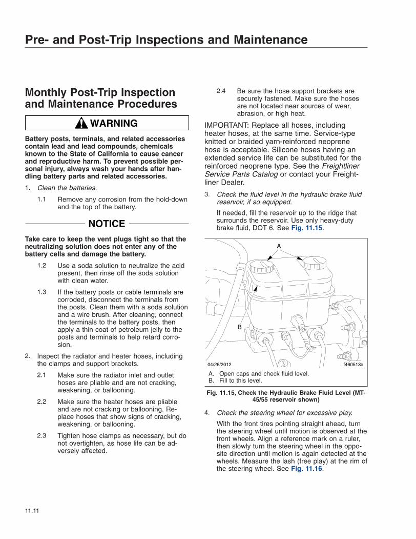
Monthly Post-Trip Inspectionand Maintenance Procedures
WARNINGBattery posts, terminals, and related accessoriescontain lead and lead compounds, chemicalsknown to the State of California to cause cancerand reproductive harm. To prevent possible per-sonal injury, always wash your hands after han-dling battery parts and related accessories.
1. Clean the batteries.
1.1 Remove any corrosion from the hold-downand the top of the battery.
NOTICETake care to keep the vent plugs tight so that theneutralizing solution does not enter any of thebattery cells and damage the battery.
1.2 Use a soda solution to neutralize the acidpresent, then rinse off the soda solutionwith clean water.
1.3 If the battery posts or cable terminals arecorroded, disconnect the terminals fromthe posts. Clean them with a soda solutionand a wire brush. After cleaning, connectthe terminals to the battery posts, thenapply a thin coat of petroleum jelly to theposts and terminals to help retard corro-sion.
2. Inspect the radiator and heater hoses, includingthe clamps and support brackets.
2.1 Make sure the radiator inlet and outlethoses are pliable and are not cracking,weakening, or ballooning.
2.2 Make sure the heater hoses are pliableand are not cracking or ballooning. Re-place hoses that show signs of cracking,weakening, or ballooning.
2.3 Tighten hose clamps as necessary, but donot overtighten, as hose life can be ad-versely affected.
2.4 Be sure the hose support brackets aresecurely fastened. Make sure the hosesare not located near sources of wear,abrasion, or high heat.
IMPORTANT: Replace all hoses, includingheater hoses, at the same time. Service-typeknitted or braided yarn-reinforced neoprenehose is acceptable. Silicone hoses having anextended service life can be substituted for thereinforced neoprene type. See the FreightlinerService Parts Catalog or contact your Freight-liner Dealer.
3. Check the fluid level in the hydraulic brake fluidreservoir, if so equipped.
If needed, fill the reservoir up to the ridge thatsurrounds the reservoir. Use only heavy-dutybrake fluid, DOT 6. See Fig. 11.15.
4. Check the steering wheel for excessive play.
With the front tires pointing straight ahead, turnthe steering wheel until motion is observed at thefront wheels. Align a reference mark on a ruler,then slowly turn the steering wheel in the oppo-site direction until motion is again detected at thewheels. Measure the lash (free play) at the rim ofthe steering wheel. See Fig. 11.16.
04/26/2012 f460513a
A
B
A. Open caps and check fluid level.B. Fill to this level.
Fig. 11.15, Check the Hydraulic Brake Fluid Level (MT-45/55 reservoir shown)
Pre- and Post-Trip Inspections and Maintenance
11.11

Excessive lash exists if steering wheel move-ment exceeds 4-3/4 inches (121 mm) with an18-inch (470 mm) steering wheel. If there is ex-cessive lash, check the steering system for wearor incorrect adjustment of the linkage and steer-ing gear before operating the vehicle.
5. Check the brake lining wear on vehiclesequipped with air brakes. Proper brake operationis dependent on periodic maintenance and in-spection of the brake linings.
5.1 Apply the parking brakes, and chock thetires to prevent vehicle movement.
5.2 If the axle assembly is not equipped witha dust shield or backing plate, measurethe axle brake lining thickness. If any ofthe brake linings are worn to less than3/16 inch (4.8 mm) at the thinnest point,replace the linings on all brake assemblieson that axle. See Group 42 of the Walk-InVan Chassis Workshop Manual for liningreplacement instructions and camshaftend play inspection.
5.3 If the axle assembly is equipped with adust shield or backing plate, remove theinspection plugs to inspect the brake liningthickness. If any of the brake linings areworn to less than approximately 3/16 inch(4.8 mm) at the thinnest point, replace thelinings on all brake assemblies on that
axle. See Group 42 of the Walk-In VanChassis Workshop Manual for lining re-placement instructions and camshaft endplay inspection.
5.4 Install the inspection plugs in the dustshields or backing plates, if so equipped.
5.5 Remove the chocks from the tires.
10/10/95 f461057
A
A. Lash Area
Fig. 11.16, Measuring Lash at the Steering Wheel
Pre- and Post-Trip Inspections and Maintenance
11.12

12
Cleaning and CareWashing and Polishing . . . . . . . . . . . . . . . . . . . . . . . . . . . . . . . . . . . . . . . . . . . . . . . . . . . . . . . . . . . . 12.1Care of Chrome Parts . . . . . . . . . . . . . . . . . . . . . . . . . . . . . . . . . . . . . . . . . . . . . . . . . . . . . . . . . . . . 12.1Dashboard and Instrument Panel Care . . . . . . . . . . . . . . . . . . . . . . . . . . . . . . . . . . . . . . . . . . . . . . . 12.1

Washing and PolishingTo extend the life of your vehicle’s finish, follow theseguidelines:
• Rinse the undercarriage regularly during thewinter months to protect it from mud and roadsalt corrosion.
• Do not let diesel fuel or antifreeze stand on apainted chassis surface. If either should occur,rinse the surface off with water.
• To prevent frame corrosion, have any nicks orother damage on the frame finish touched upas soon as possible.
To prevent delamination and deterioration of labelsand stickers on the cab, follow these guidlines care-fully:
• Do not pressure wash the label or sticker orsurfaces near it.
• Do not use strong alkaline soaps on or nearthe label or sticker.
Care of Chrome PartsTo prevent rust, keep chrome parts clean and pro-tected at all times. This is especially important duringwinter driving and in coastal areas where there isexposure to salt air.
When cleaning chrome parts, use clean water and asoft cloth or sponge. A mild detergent may also beused.
Sponge gently, then rinse. If necessary, use a non-abrasive chrome cleaner to remove stubborn rust orother material. Do not use steel wool.
To help protect the chrome after cleaning, apply acoat of polishing wax to the surface. Never use waxon parts that are exposed to high heat, such as ex-haust pipes.
Dashboard and InstrumentPanel Care
NOTICEWhen cleaning the dashboard, instrument panel,or gauge lens covers, do not use Armor-All Pro-tectant®, STP Son-of-a-Gun®, window cleaner, or
other equivalent treatments. These cleaners con-tain vinyl plasticizers which can cause stresscrazing in the interior plastic panels and can re-sult in cracking of the panels. Some cleaners canalso have an adverse effect on the clear plasticof instrument panels and gauge lens covers, re-sulting in a foggy or cloudy appearance. Thistype of damage is not covered by vehicle war-ranty.
To clean the dashboard, instrument panel, and gaugelens covers, use a cloth dampened with warm soapywater. Make certain to wring the cloth out well beforecleaning, as excess water will damage the electricalcomponents.
Cleaning and Care
12.1

13
In an EmergencyHazard Warning Lights . . . . . . . . . . . . . . . . . . . . . . . . . . . . . . . . . . . . . . . . . . . . . . . . . . . . . . . . . . . . 13.1Towing . . . . . . . . . . . . . . . . . . . . . . . . . . . . . . . . . . . . . . . . . . . . . . . . . . . . . . . . . . . . . . . . . . . . . . . . . 13.1Emergency Starting With Jumper Cables . . . . . . . . . . . . . . . . . . . . . . . . . . . . . . . . . . . . . . . . . . . . . 13.1Changing a Flat Tire . . . . . . . . . . . . . . . . . . . . . . . . . . . . . . . . . . . . . . . . . . . . . . . . . . . . . . . . . . . . . . 13.3Running Out of Fuel . . . . . . . . . . . . . . . . . . . . . . . . . . . . . . . . . . . . . . . . . . . . . . . . . . . . . . . . . . . . . . 13.3

Hazard Warning LightsThe hazard warning light tab is located on the steer-ing column. See Fig. 13.1. Pull the tab out to acti-vate the hazard warning lights. When the hazardwarning light tab is pulled out, all of the turn signallights and both of the indicator lights on the instru-ment panel will flash. To cancel the hazard warninglights, push the tab in.
An additional hazard warning light control knob maybe installed on the dash near the headlight controls.To activate the hazard warning lights, pull the knobout.
TowingSee Chapter 14 for towing information.
Emergency Starting WithJumper CablesWhen using jumper cables, follow the instructionsbelow.
WARNINGBatteries release explosive gas. Do not smokewhen working around batteries. Put out all flamesand remove all sources of sparks or intense heatin the vicinity of the battery. Do not allow the ve-
hicles to touch each other. Do not lean over thebatteries when making connections, and keep allother persons away from the batteries. Failure tofollow these precautions could lead to severepersonal injury as a result of an explosion oracid burns.
NOTICEMake sure that both starting systems are thesame voltage. Electronic devices on both ve-hicles can be damaged when connected to a ve-hicle with a different operating voltage.
1. Apply the parking brakes and turn off all lightsand other electrical devices.
IMPORTANT: Do not attempt to jump start adamaged battery.
2. Access the batteries under the passenger steps.
NOTICEAlways connect the batteries and jumper cablescorrectly (positive-to-positive and negative-to-negative). Connecting a charging device back-wards (positive-to-negative) can severely damagethe vehicle electrical content and cause non-warrantable failures.
3. Connect the positive (+) jumper cable to thepositive terminal on the discharged battery. SeeFig. 13.2.
4. Connect the other end of the positive jumpercable to the positive terminal on the booster bat-tery providing the charge.
WARNINGDo the next step exactly as instructed and do notallow the clamps of one cable to touch theclamps of the other cable. Otherwise, a sparkcould occur near a battery, possibly resulting insevere personal injury from explosion or acidburns.
5. Connect the negative (-) jumper cable to thenegative terminal on the booster battery.
6. Connect the other end of the negative jumpercable to the negative ground stud on the vehiclerequiring the jump start.
11/27/2007 f462122
Fig. 13.1, Hazard Warning Light Tab
In an Emergency
13.1

7. Start the engine of the vehicle providing the jumpstart and let the engine run for a few minutes tocharge the batteries of the other vehicle.
NOTICEDo not crank the engine for more than 30 sec-onds at a time during any of the following proce-dures. Wait two minutes after each try to allow
the starter to cool. Failure to do so could causestarter damage.
8. Attempt to start the engine of the vehicle with thebatteries receiving the charge.
9. When the engine starts, let it idle for a few min-utes.
01/07/2011 f545725
1
2
3
4
A
C
EB
D
−−
−
−
+
+
+
+
+
+
−
−
Disconnect jumper cables in the REVERSE order that they were connected.
A. Discharged BatteryB. Negative Ground Stud
C. Positive Jumper CableD. Negative Jumper Cable
E. Booster Battery
1. 1st Connection: Positive Jumper Cable to Discharged Battery2. 2nd Connection: Positive Jumper Cable to Booster Battery3. 3rd Connection: Negative Jumper Cable to Booster Battery4. 4th Connection: Negative Jumper Cable to Negative Ground Stud (discharged battery)
Fig. 13.2, Jumper Connections (three battery system shown for clarity)
In an Emergency
13.2

WARNINGDo the next step exactly as instructed and do notallow the clamps of one cable to touch theclamps of the other cable. Otherwise, a sparkcould occur near a battery, possibly resulting insevere personal injury from explosion or acidburns.
10. Disconnect the negative jumper cable from thenegative cable stud on the jump started vehicle.
11. Disconnect the negative jumper cable from thebooster battery.
12. Disconnect the positive cable from the boosterbattery.
13. Disconnect the other end of the positive jumpercable from the jump started vehicle.
14. Close the battery access door at the passengersteps.
Changing a Flat TireIMPORTANT: If a flat tire occurs while driving,gradually decrease vehicle speed. Holding thesteering wheel firmly, move the vehicle to a safelocation as quickly as possible.
1. If possible, stop the vehicle on a level surfaceaway from traffic.
2. Apply the parking brake and place the transmis-sion in Park (P). Turn the ignition switch to theOFF position.
3. Turn on the hazard warning lights.
4. Remove the spare wheel, jack, jack handle, andlug wrench (if so equipped) from storage.
5. Block the wheel diagonally opposite the wheelbeing changed.
NOTICEThe jacking point for the front and rear wheels isdirectly under the axle. Insert a wooden blockbetween the axle and the jack. Do not jack di-rectly on the axle housing.
6. Place the jack on a solid surface. Insert the jackhandle and pump the handle to slightly raise thevehicle. Do not raise the wheel off of the ground.
Loosen the wheel lug nuts, but do not removethem.
NOTE: Dual stud-piloted rear wheels are at-tached using inner and outer (2-element) lugnuts. The larger nut retains the outer dual (stud-piloted), 2-piece wheel. The inner square nutretains the inner dual (stud-piloted) wheel. Re-move and install these nuts separately. The reardual outer lug nut must be removed and loos-ened to check and retighten the inner nut. Hub-piloted wheels use a single outer lug nut thatholds both discs on the hub pilot.
7. Raise the vehicle until the wheel is off of theground. Remove the lug nuts and the wheel.
8. Install the spare wheel and lug nuts. Make surethat the beveled sides of the nuts face inward.
9. In a star pattern, tighten the nuts evenly untilsnug.
10. Lower the vehicle until the wheel touches theground. Tighten the nuts in the same pattern 450to 500 lbf·ft (610 to 678 N·m).
11. Finish lowering the vehicle to the ground, thenremove the jack.
12. Remove the block, then stow the jack, jackhandle, and lug wrench (if so equipped).
13. After operating the vehicle for 50 to 100 miles(80 to 161 km), retighten the nuts (for stud-piloted dual discs, all inner, then all outer) 450 to500 lbf·ft (610 to 678 N·m).
Running Out of FuelDiesel Engines
WARNINGDiesel fuel is flammable. When you approach avehicle and the smell of diesel fuel is present,immediately shut off all engines and ignitionsources. Avoid causing sparks and stay awayfrom arcing switches and equipment. Extinguishcigarettes, pilot lights, flames, or other sourcesof ignition in the area and adjacent areas. Imme-diately provide extra ventilation to the area. Donot start the vehicle or any other type of equip-ment until the fuel leak is corrected and the area
In an Emergency
13.3

cleared of fuel. Failure to perform these actionscould lead to the ignition of the fuel, which couldcause personal injury or death, or severe prop-erty damage.
If the vehicle runs out of fuel, try to stop the vehicleon a level location away from traffic. Add at least 2gallons (8 liters) of fuel to the fuel tank in order torestart the engine. If the vehicle is not level, up to 4gallons (16 liters) of fuel may be required. Prolongedengine cranking may be required to pump fuel fromthe fuel tank to the engine before the engine willstart.
NOTICEDo not crank the engine for more than 30 sec-onds at a time. Wait two minutes after each try toallow the starter to cool. Failure to do so couldcause starter damage.
If the vehicle will not start by cranking the engine, thefuel system may need to be primed. See the appli-cable engine manufacturer’s operation and mainte-nance manual.
Compressed Natural Gas (CNG)Engines
WARNINGCompressed natural gas is highly flammable.When inspecting or servicing a vehicle, avoidcausing sparks or using arcing switches andequipment. Extinguish cigarettes, pilot lights,flames, or other sources of ignition. Failure toperform these actions or to take other precau-tions could lead to the ignition of the natural gas,which could cause serious bodily injury, death,or severe property damage.
If the vehicle runs out of fuel, park on a level locationaway from traffic. Restart the engine after adding atleast 30 psi (207 kPa) of fuel.
NOTICEDo not crank the engine for more than 30 sec-onds at a time. Wait two minutes after each try toallow the starter to cool. Failure to do so couldcause starter damage.
In an Emergency
13.4

14
TowingFront Towing Hookup . . . . . . . . . . . . . . . . . . . . . . . . . . . . . . . . . . . . . . . . . . . . . . . . . . . . . . . . . . . . . 14.1Rear Towing Hookup . . . . . . . . . . . . . . . . . . . . . . . . . . . . . . . . . . . . . . . . . . . . . . . . . . . . . . . . . . . . . 14.1

Front Towing Hookup
WARNINGDo not tow an unbraked vehicle if the combinedweight of both vehicles is more than the sum ofthe gross axle weight ratings (GAWR) of the tow-ing vehicle. Otherwise brake capacity will be in-adequate, which could result in personal injury ordeath.
IMPORTANT: When it is necessary to tow thevehicle, make sure the instructions below areclosely followed to prevent damage to the ve-hicle.
NOTE: Towing rules and regulations vary fromfederal, state, local, and transit authority. Theselaws must be followed when towing the vehicle.
Front Towing Hookup1. Disconnect the battery ground cables.
NOTICEFailure to remove the axle shafts when towingthe vehicle with the rear wheels on the groundcould result in damage to the transmission andother parts.
Remove the rear driveshaft before towing a ve-hicle equipped with a hydraulic hybrid system.Failure to do so will damage the hydraulic hybridcomponents. Once the driveshaft has been re-moved, do not attempt to start a vehicleequipped with a hydraulic hybrid drive system.Doing so will damage the hydraulic hybrid sys-tem components.
2. Remove the drive axle shafts.
3. On a vehicle equipped with a hydraulic hybridsystem, remove the rear driveshaft.
IMPORTANT: Cover the ends of the hubs withmetal plates or plywood cut to fit the axle open-ing, and drilled to fit the axle shaft studs. Thisprevents lubricant from leaking out, and willkeep contaminants from getting into the axlelubricant and damaging the wheel bearings.
4. If additional clearance is needed for towing, re-move the bumper.
5. Attach the towing device. Due to the many vari-ables that exist in towing, positioning the liftingand towing device is the sole responsibility of thetowing-vehicle operator.
NOTICEFailure to protect the frame rails from the chainscould cause damage, leading to eventual framefailure.
6. Lift the vehicle and secure the safety chains. Ifextra towing clearance is needed, remove thefront wheels.
7. Connect the clearance lights, taillights, and sig-nal lights. Connect any special towing lights re-quired by local regulations.
WARNINGFailure to chock the tires or connect the towtruck’s air brake system before releasing thespring parking brakes could allow the disabledvehicle to suddenly roll. This could cause prop-erty damage or personal injury.
NOTICEBefore attempting to tow a vehicle with an airsuspension (and during the towing operation),ensure that the air suspension is properlycharged. Charge the suspension through theSchrader valve on the air dryer. Attempting totow a vehicle with an improperly charged air sus-pension may result in damage to the chassis andbody.
8. Chock the tires on the disabled vehicle and con-nect the towing vehicle’s air brake system to thevehicle being towed. Then, release the springparking brake and remove the chocks.
9. On vehicles equipped with hydraulic disc brakesbe sure the parking brake is released beforestarting the towing process.
Rear Towing Hookup1. Position the front tires pointing straight ahead,
and secure the steering wheel in this position.
Towing
14.1

2. Disconnect the battery ground cable.
WARNINGDue to the many variables that exist in towing,positioning the lifting and towing device is thesole responsibility of the tow vehicle operator.The operator must be familiar with standard tow-ing industry safety measures. Improper proce-dures could result in personal injury or death.
3. Attach the towing device.
4. Lift the vehicle, and secure the safety towingchains. If additional clearance is needed, removethe bumper extension, if so equipped.
5. Connect the clearance lights, taillights, and sig-nal lights. Also connect any special towing lightsrequired by local regulations.
Towing
14.2

15
GM Gasoline EngineStarting the Engine . . . . . . . . . . . . . . . . . . . . . . . . . . . . . . . . . . . . . . . . . . . . . . . . . . . . . . . . . . . . . . . 15.1Engine Break-In . . . . . . . . . . . . . . . . . . . . . . . . . . . . . . . . . . . . . . . . . . . . . . . . . . . . . . . . . . . . . . . . . 15.3Fast Idle System . . . . . . . . . . . . . . . . . . . . . . . . . . . . . . . . . . . . . . . . . . . . . . . . . . . . . . . . . . . . . . . . . 15.3Engine Coolant . . . . . . . . . . . . . . . . . . . . . . . . . . . . . . . . . . . . . . . . . . . . . . . . . . . . . . . . . . . . . . . . . . 15.4Fuel . . . . . . . . . . . . . . . . . . . . . . . . . . . . . . . . . . . . . . . . . . . . . . . . . . . . . . . . . . . . . . . . . . . . . . . . . . . 15.4Engine Oil . . . . . . . . . . . . . . . . . . . . . . . . . . . . . . . . . . . . . . . . . . . . . . . . . . . . . . . . . . . . . . . . . . . . . . 15.5Ametek Instrument Panel . . . . . . . . . . . . . . . . . . . . . . . . . . . . . . . . . . . . . . . . . . . . . . . . . . . . . . . . . . 15.5Warning and Indicator Lights . . . . . . . . . . . . . . . . . . . . . . . . . . . . . . . . . . . . . . . . . . . . . . . . . . . . . . 15.11Speedometer and Tachometer . . . . . . . . . . . . . . . . . . . . . . . . . . . . . . . . . . . . . . . . . . . . . . . . . . . . . 15.18Standard Instruments . . . . . . . . . . . . . . . . . . . . . . . . . . . . . . . . . . . . . . . . . . . . . . . . . . . . . . . . . . . . 15.18

Starting the EngineIMPORTANT: For service issues and questions,call 1-800-FTL-HELP and follow the prompts forgasoline engines. Representatives will be ableto answer questions and diagnose mechanicalissues, as well as provide detailed service repairinformation.
General InformationNOTE: Before starting the engine, read Chap-ter 2 and Chapter 3 in this manual for detailedinformation on how to read the instruments andoperate the controls.
Before operating the vehicle, perform the enginepretrip inspection and daily maintenance checksin Chapter 10 and Chapter 11 of this manual.
NOTICEIf a vehicle does not start on the first attempt,make sure that the engine has completelystopped rotating before reapplying the starterswitch. Failure to do so can cause the pinion torelease and re-engage, which could cause ringgear and starter pinion damage.
IMPORTANT: Ring gear and starter pinion dam-age caused by improper starting procedures isnot warrantable.
NOTICENever attempt to start any electronic engineusing ether or any other starting fluid. Seriousengine damage could result.
1. Set the parking brake.
2. Turn the ignition switch to the ON position. SeeFig. 15.1 for the four-position ignition switch andFig. 15.2 for the three-position ignition switch.
3. Make sure that the transmission shift control is inNeutral (N) or Park (P), and that the park brakeis set.
IMPORTANT: Do not depress the throttle pedalwhile starting the engine.
4. Turn the ignition switch to the START position.After the engine starts, release the key.
NOTICEDo not crank the engine for more than 30 sec-onds at a time. Wait two minutes after each try toallow the starter to cool. Failure to do so couldcause starter damage.
5. Bring the engine up to operating speed graduallyas it warms up and develops stable oil pressure.
IMPORTANT: When the engine is started, ittakes a short time to build up a lubricating oilfilm between the shafts and bearings, and be-tween the pistons and cylinder walls. The oilpressure gauge indicates any drop in lubricating
07/10/96
1
2
34
f601179
1. Accessory (optional)2. Off
3. On4. Start
Fig. 15.1, Four-Position Ignition Switch
05/10/2001
1
23
f601179a
1. Off 2. On 3. Start
Fig. 15.2, Three-Position Ignition Switch
GM Gasoline Engine
15.1

oil pressure within 15 seconds of engine start-up.
6. If the engine does not start after 5 to 10 sec-onds, especially in very cold weather below 0°F(–18°C), it could be flooded with too much gaso-line. Try pushing the throttle pedal all the way tothe floor and holding it there as you hold the keyin the START position for up to 15 seconds
NOTICEDo not crank the engine for more than 30 sec-onds at a time. Wait two minutes after each try toallow the starter to cool. Failure to do so couldcause starter damage.
7. If the vehicle starts briefly but then stops again,repeat the process. This will clear the excessgasoline from the engine.
8. Do not race the engine immediately after startingit. Operate the engine and transmission gentlyuntil the oil warms up and lubricates all of themoving parts.
MIL Lamp
NOTICEIf the vehicle is continually driven when the MILlamp is activated, the emission controls may notwork as well, the vehicle fuel economy may notbe as good, and the engine may not run assmoothly. This could lead to costly repairs thatmay not be covered by the vehicle warranty.
Modifications made to the engine, transmission,exhaust, intake, or fuel system of the vehicle, orreplacing the original tires with tires that do notmeet the same tire performance criteria, can af-fect the vehicle’s emission controls and cancause the MIL lamp to activate. Modifications tothese systems could lead to costly repairs notcovered by the vehicle warranty. This could alsoresult in a failure to pass required emission in-spection and/or maintenance tests.
When the MIL lamp activates, it can either flash onand off, or remain on with a constantly illuminatedlamp.
MIL Lamp Flashes
IMPORTANT: If the MIL lamp flashes on and offwhile driving the vehicle, the driver should find asafe place to park and stop the vehicle immedi-ately. See Fig. 15.3 for an example of the MILlamp. The vehicle should be taken to an autho-rized Freightliner dealer as soon as possible forservice. Continued driving with an illuminatedMIL lamp could damage the emission systemand void the warranty.
The MIL lamp illuminates to indicate a fault that af-fects the emission system; a misfire condition is oneexample. Diagnosis and service may be required. Toprevent serious damage to the vehicle, observe thefollowing guidelines:
• Reduce vehicle speed.
• Avoid hard accelerations.
• Avoid steep uphill grades.
Once the MIL lamp begins flashing, the driver shouldfind a safe place to stop. Turn the vehicle off, wait atleast 10 seconds, and then restart the vehicle. If theMIL lamp continues to flash, observe the guidelineslisted above and see a dealer for service as soon aspossible.
MIL Lamp is on Constant (steady)A constant (steady) MIL lamp indicates that an emis-sion system malfunction has been detected on thevehicle. Diagnosis and service may be required. Thefollowing information may correct an emissions sys-tem malfunction.
09/25/2006 f610814a
Fig. 15.3, MIL Lamp
GM Gasoline Engine
15.2

• Make sure the fuel cap is fully installed. Thediagnostic system can determine if the fuel caphas been left off or is incorrectly installed. Amissing or loose fuel cap allows fuel to evapo-rate into the atmosphere. A few driving tripswith the fuel cap properly installed should turnthe MIL lamp off.
• If the vehicle has been driven through a deeppuddle of water, the system could be wet. In-spect the electrical system and make sure it isnot wet. This condition is usually correctedwhen the electrical system dries out. A fewdriving trips should turn the MIL lamp off.
• Make sure to fuel the vehicle with quality fuel.Poor fuel quality causes the engine not to runas efficiently as designed and can cause—
– stalling after start-up;
– stalling when the vehicle is changed intogear;
– misfiring;
– hesitation on acceleration; or
– stumbling on acceleration.
If one or more of these conditions occur, change thefuel brand used. At least one full tank of the properfuel will be required to turn the MIL lamp off. SeeFuel in this chapter for information on the proper fuelto use.
If the MIL lamp will not go off after performing theabove steps, your dealer can check the vehicle. Thedealer has the proper test equipment and diagnostictools to fix any mechanical or electrical problems thatmay have developed. A GM dealership can alsocheck gasoline engines.
Engine Break-InThe engine will perform better over time if the guide-lines below are followed.
• Keep the vehicle speed at 55 mph (88km/h) orless for the first 500 miles (805 km).
• Do not drive at one constant speed, either fastor slow, for the first 500 miles (805 km). Do notmake full-throttle starts. Avoid downshifting tobrake or slow the vehicle.
• Avoid making hard stops for the first 200 miles(322 km). During this time, the new brakes are
not yet broken in. Making hard stops with newbrakes can lead to premature wear and earlyreplacement. This guideline should be followedeach time new brakes are installed.
• Do not tow a trailer during the break-in period.
Once the break-in period has been met, enginespeed and load can be gradually increased.
Fast Idle SystemNOTE: If the vehicle has this feature, it is avail-able for use only with cruise control. There arethree preset speeds (800, 900, or 1000 rpm)available.
The fast idle system can be used to increase engineidle speed whenever the following conditions aremet.
• The brake pedal is not pressed.
• The vehicle must not be moving and thethrottle must not be pressed.
Fast Idle Operation1. To enable the fast idle system, press and release
the cruise control ON/OFF switch.
2. For the preset fast idle, press and release thecruise control set switch. This will set the presetfast idle speed.
IMPORTANT: The fast idle system does nothave any type of light activation in the instru-ment panel. The only light that will be illumi-nated is the cruise indicator.
Any of the following actions will turn off the fast idlesystem.
• Applying the brake.
• The transmission shifter is moved out of Park(P) or Neutral (N); this will engage the trans-mission.
• Selecting the cruise control ON/OFF switchwhen it was previously on.
GM Gasoline Engine
15.3

Engine Coolant
NOTICEIf an improper coolant mixture is used, the en-gine could overheat and be damaged. The repaircost would not be covered by the warranty. Toomuch water in the mixture can freeze and crackthe engine, radiator, heater core, and other parts.
For the gasoline engine, a 50/50 mixture of cleanwater and DEX-COOL® coolant should be used. Ifthis mixture is used, nothing else needs to be added.This mixture will—
• give freezing protection down to –34°F(–37°C);
• give boiling protection up to 265°F (129°C);
• protect against rust and corrosion;
• not damage aluminum parts;
• help keep the proper engine temperature.
NOTICEIf extra inhibitors and/or additives are used in thevehicle’s cooling system, the cooling systemcould be damaged. Use only the proper mixtureof the engine coolant and water listed here forthe cooling system.
FuelIMPORTANT: Using the recommended fuel(gasoline) is important for proper maintenanceof the engine. To help keep the engine cleanand maintain optimum vehicle performance,General Motors recommends the use of gaso-line advertised as TOP TIER detergent gasoline.Any resulting engine damage due from the useof unapproved fuel (gasoline) would not be cov-ered by the vehicle warranty.
NOTICEDo not use ethanol fuel (E85) in the vehicle. Theengine is not designed for this fuel, and seriousengine damage will result if it is used.
Gasoline OctaneUse regular unleaded gasoline with a posted octanerating of 87 or higher. If the octane rating is less than87, an audible knocking noise may occur. If this hap-pens, use a gasoline rated at 87 octane or higher assoon as possible. If gasoline rated at 87 octane orhigher is being used and a heavy knocking is heard,the engine needs service.
Gasoline SpecificationsGasoline should meet the American Society for Test-ing and Materials (ASTM) specification D4814 in theUnited States or CAN/CGSB-3.5 or 3.511 in Canada.Some gasolines contain an octane-enhancing addi-tive called methylcyclopentadienyl manganese tricar-bonyl (MMT). General Motors does not recommendthe use of gasolines containing MMT. Gasoline con-taining MMT can reduce the life of spark plugs andthe performance of the emission control systemcould also be affected. The malfunction indicatorlamp (MIL) might come on if gasoline with MMT isused. If this happens, take the vehicle to a dealer forservice.
AdditivesTo provide cleaner air, all gasoline in the UnitedStates is now required to contain additives that helpprevent engine and fuel system deposits from form-ing, allowing the emission control system to workproperly. In most cases, you should not have to addanything to the fuel. However, some gasolines con-tain only the minimum amount of additive required tomeet EPA regulations. To help keep fuel injectorsand intake valves clean, or if the vehicle experiencesproblems due to dirty injectors or valves, look forgasoline that is advertised as TOP TIER detergentgasoline.
For those who do not use TOP TIER detergent gaso-line regularly, one bottle of GM Fuel System Treat-ment Plus, added to the fuel tank at every engine oilchange, can help clean deposits from fuel injectorsand intake valves. GM Fuel System Treatment Plusis the only gasoline additive recommended by Gen-eral Motors.
GM Gasoline Engine
15.4

Engine Oil
NOTICEUse engine oil that is identified as meeting GMstandard GM6094M and showing the AmericanPetroleum Institute (API) starburst symbol. Fail-ure to use the recommended oil can result in en-gine damage and will void the engine warranty.
When determining the type of engine oil to use, lookfor three things.
• Use only an oil that meets GM standardGM6094M.
• Oil grade SAE 5W–30 is best for the engine.Do not use SAE 10W–40 or 20W–50.
• The API starburst symbol. See Fig. 15.4.
If the vehicle is being operated in an area of extremecold, the use of SAE 5W–30 oil will provide easiercold starting for the engine.
Engine Oil AdditivesDo not add anything to the oil. The recommendedoils with the API starburst symbol that meet GM stan-dard GM6094M are all that is needed for good per-formance and engine protection.
Engine Oil Flushing
NOTICEEngine oil system flushing is not recommendedand could cause engine damage not covered bythe engine warranty.
Checking the Engine OilIt is important to check the oil regularly and keep it atthe proper level. In order to get an accurate reading,the oil must be warm and the vehicle must be onlevel ground.
1. Turn off the engine and give the oil several min-utes to drain back into the oil pan. If this is notdone, the oil dipstick may not show the actuallevel.
2. Pull out the dipstick and clean it with a papertowel or cloth, then push the dipstick back in allthe way. Remove it again, keeping the tip down,and check the level.
3. If the oil is below the cross-hatched area at thetip of the dipstick, add at least one quart (liter) ofthe recommended oil. See Fig. 15.5.
Changing the Engine OilThe engine oil must be changed every 3000 miles(4827 km). See maintenance operation 01–03 in theWalk-In Van Chassis Maintenance Manual for de-tailed instructions.
Ametek Instrument PanelThe following information describes the Ametek in-strument panel, used with gasoline engines. The in-strument panel is shown in Fig. 15.6.
NOTE: The instrument panel is shown with astandard U.S. speedometer, which shows milesper hour (mph) more prominently than kilome-ters per hour (km/h).
08/05/2010 f012187
Fig. 15.4, API Symbol
08/05/2010 f012186
NOTE: Oil should be above the cross-hatched area ofthe dipstick.
Fig. 15.5, Oil Dipstick
GM Gasoline Engine
15.5

Message Display CenterThe message display is a graphical, backlit, liquidcrystal display (LCD) that relays information to thevehicle operator. The messages displayed include:
• Odometer
• Trip Odometer 1/Trip Odometer 2
• Chassis Battery Voltage
• Instantaneous Fuel Rate
• Average Fuel Rate
• Gear Attained Status
• Transmission Temperature
• Hour Meter
• Boost Pressure
• Engine Oil Pressure
• Coolant Temperature
• Fuel Level
• Percent Engine Load
• Engine RPM
During normal operation, the LCD displays the odom-eter value and chassis battery voltage on the topline, and driver selected parameters, such as the tripodometer and fuel rate, on the second and thirdlines.
10/24/2014 f611240a
1
2
3
4 5
6 7
8
UNLEADED FUEL ONLY
1. Fuel Level Gauge2. Dash Message Center3. Speedometer
4. Engine Oil Pressure Gauge5. Coolant Temperature Gauge6. Dash Driver Display Screen
7. Toggle Button, Down8. Toggle Button, Right
Fig. 15.6, Gauge Layout (typical, U.S.)
GM Gasoline Engine
15.6

Priority MessagesPriority messages (including warning messages) aredisplayed in the LCD due to various inputs or datamessages. Unless noted otherwise, the priority mes-sage will take over the whole screen, allowing mul-tiple messages to be displayed in five second inter-vals.
Self-TestWhen the ignition is turned on, a required self-testautomatically begins. Gauge needles will reset tozero during the self-test, and then immediately moveto the position dictated by the data received. Duringthis time, the warning lights, alarm (buzzer), anddriver display screen will also perform a self-test.
NOTE: The driver can activate or deactivate thestart-up self-test by accessing the setup menu.
Menu SystemThe menu system is shown on the driver displayscreen once the self-test is finished. The menu sys-tem responds to input from the driver and remainsactive as long as the ignition is on. In order for thedriver to operate the menu system, the ignition mustbe ON, and the park brake must be set (ON). Themain features of the menu system are describedbelow.
• Setup—this is used to set various parameters,which are saved when the ignition is turned off.Setup has select display units, startup screen,LCD contrast, and reset parameters.
• Maintenance—shows various maintenance in-tervals such as engine oil, air filter, etc.
• Diagnostics—this is used for setting and read-ing inputs and outputs and checking thegauges. It also shows the hardware and soft-ware version of the instrument panel, and hasmenus to retrieve active error codes from theengine, transmission, and ABS controllers.
NOTE: No lines can be highlighted in the menusystem screen. To get to the sections that canbe highlighted, press the right arrow toggle but-ton and hold it for two seconds. The displayscreen will change and the options shown canthen be highlighted. Once a selection has beenchosen and changes are made, press the right
arrow toggle button to go back to the main mes-sage display screen.
Setup MenuSelect Display UnitsThe set units screen allows the driver to choose be-tween English or metric units of measurement for thedisplayed values. To navigate to the set units screen,see Fig. 15.7, screens H, I, and J.
Startup ScreenThe startup screen selection allows the driver to turnthe startup screen on or off.
LCD ContrastSelect contrast from the menu to set the LCD con-trast. Use the down toggle button to set the contrastto the desired level. To navigate to the contrastscreen, see Fig. 15.7, screen M.
Reset ParametersThe reset parameters screen is included with ve-hicles that have the Allison transmission prognosticsfeature.
Maintenance MenuThe maintenance menu has the following three submenus:
• maintenance intervals
• transmission oil life remaining
• transmission oil filter life monitor
Maintenance IntervalsThe maintenance intervals menu allows the driver toset the change intervals for engine oil and engine airfilter. If the intervals are set to zero, the maintenancewarnings must be disabled.
Transmission Oil Life RemainingIf transmission prognostics are enabled, this menuindicates how much useful oil life remains.
Transmission Oil Filter Life MonitorIf transmission prognostics are enabled, the trans-mission oil filter life monitor tells the driver if thetransmission oil filter is clogged and in need of repair.A message will appear on the display screen as
GM Gasoline Engine
15.7
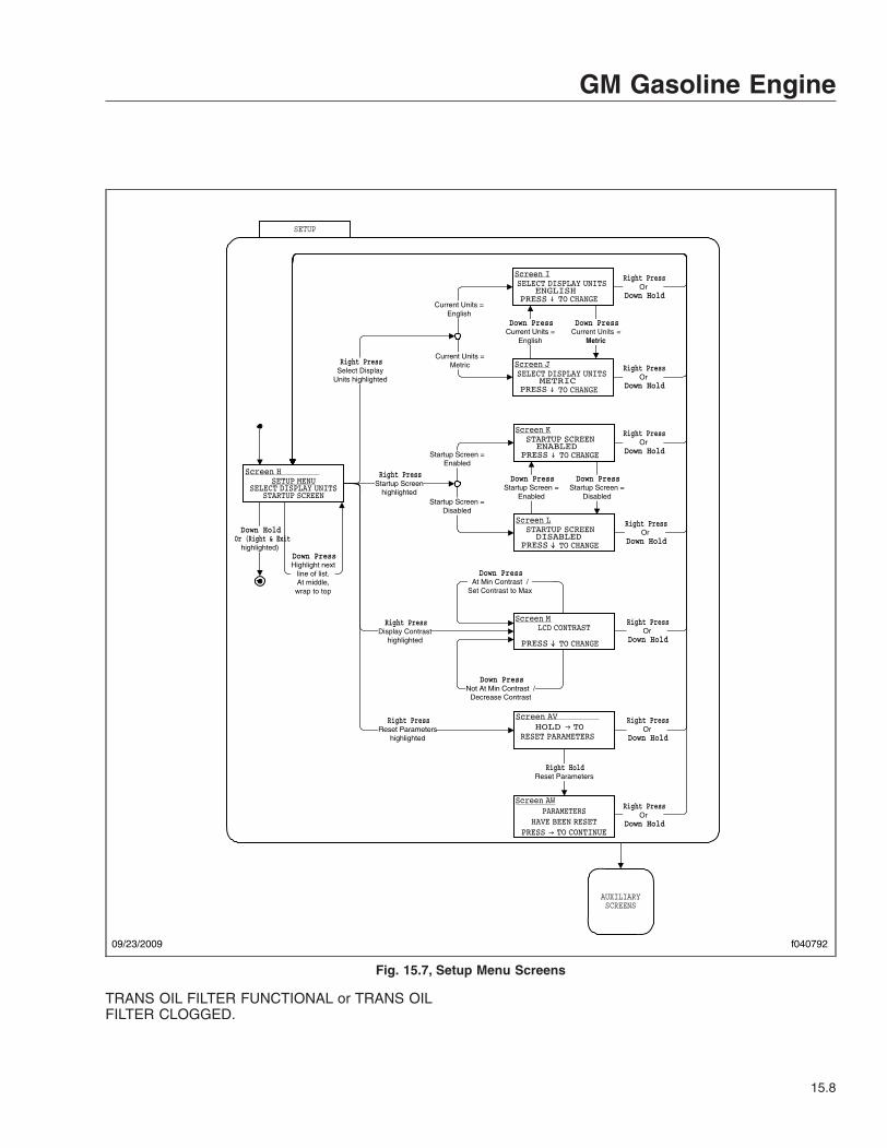
TRANS OIL FILTER FUNCTIONAL or TRANS OILFILTER CLOGGED.
SETUP
Down HoldOr (Right & Exit
highlighted)
Down PressCurrent Units =
Metric
Down PressCurrent Units =
English
Current Units =English
Current Units =Metric
Down PressStartup Screen =
Disabled
Down PressStartup Screen =
Enabled
Startup Screen =Enabled
Startup Screen =Disabled
Down PressNot At Min Contrast /
Decrease Contrast
Down PressAt Min Contrast /
Set Contrast to Max
Right PressStartup Screen
highlighted
Right PressSelect Display
Units highlighted
Right PressDisplay Contrast
highlighted
Right PressOr
Down Hold
Right PressOr
Down Hold
Right PressOr
Down Hold
Right PressOr
Down Hold
Right PressOr
Down Hold
Down PressHighlight next
line of list.At middle,wrap to top
Right HoldReset Parameters
Right PressReset Parameters
highlighted
Right PressOr
Down Hold
Right PressOr
Down Hold
AUXILIARYSCREENS
09/23/2009 f040792
Fig. 15.7, Setup Menu Screens
GM Gasoline Engine
15.8

Diagnostic MenuThe diagnostic menu contains the following items:
• engine faults
• transmission faults
• ABS faults
• check outputs
• odometer diagnostics
• check gauges
• check indicators (warning lamps)
• check LCD
• check binary inputs
• check analog inputs
• check datalink
• hardware/software version
All of the items in the diagnostic menu can be ac-cessed by using the toggle buttons and selecting theauxiliary screens. Then navigate to the diagnosticsub-menu. Some of the more frequently used diag-nostic menus are described further below.
Engine FaultsThis screen displays engine fault codes that are re-ceived from the engine electronic control unit (ECU).To navigate to the engine fault screen, see Fig. 15.8,screen AA.
Transmission FaultsThis screen displays transmission fault codes thatare received from the transmission ECU. To navigateto the transmission fault screen, see Fig. 15.8,screen AB.
ABS DiagnosticsThis screen displays Antilock Brake System (ABS)fault codes that are received from the ABS ECU. Tonavigate to the ABS diagnostic screen, see Fig. 15.8,screen AC.
Check GaugesThe check gauges screen allows the driver to seteach gauge as a percentage of scale (either 0, 50, or100%), as shown in the LCD. To navigate to thecheck gauges screen, see Fig. 15.9, AG screens.
Warning LampThe warning lamp screen allows the driver to testeach warning lamp (not the vehicle load) on and thenoff, displaying the lamp name and status in the LCD.To navigate to the warning lamp screen, seeFig. 15.9, screen AH.
Check LCDSelecting the check LCD screen displays the Freight-liner Custom Chassis Corporation (FCCC) logo innormal and reverse video three times and then re-turns to the menu. To navigate to the check LCDscreen, see Fig. 15.9, screen AI.
Check Binary InputsThe check binary inputs screen displays the pin num-ber and status of each binary input. The toggle but-tons allow the driver to select each binary input. Thisinformation is continuously updated to assist introubleshooting. To navigate to the check binary in-puts screen, see Fig. 15.9, screen AJ.
Check Analog InputsThe check analog inputs screen displays the pinnumber and actual value of each analog input de-fined in the system. The toggle buttons allow thedriver to select each analog input. This information iscontinuously updated to assist in troubleshooting. Tonavigate to the check analog input screen, seeFig. 15.10, screen AK.
Check DatalinkThe check datalink screen allows the driver to viewall devices that communicate on the J1939, J1587,and GMLAN datalinks. To navigate to the check da-talink screen, see Fig. 15.10, screen AL.
Menu NavigationThe menu navigation screens are provided to illus-trate the menu system. The paths to specific screensare shown, along with instructions for using thetoggle buttons to move from one screen to another.See Fig. 15.77, Fig. 15.8, Fig. 15.99, Fig. 15.10,Fig. 15.1111, Fig. 15.12, Fig. 15.1313, Fig. 15.14,Fig. 15.1515, Fig. 15.16, Fig. 15.1717, Fig. 15.18,and Fig. 15.1919.
IMPORTANT: Follow the steps below to changethe three items (also known as favorites) shownin the message display center. The message
GM Gasoline Engine
15.9

display center is referred to as screen C inFig. 15.13.
1. With the vehicle in park, turn the ignition to RUN,and allow the self test to complete.
2. Press the down toggle button to select an item tochange. The selected item will now be high-lighted.
3. Press the right toggle button once to enter thefavorites display menu, shown in Fig. 15.13, asscreen D.
4. Use the down toggle button to scroll through theavailable items.
5. Highlight the new item, then press the righttoggle button. The selected item will now appearin the message display center.
Diagnostics
Note 5:Screen Z scrolls to display the following items: ENGINE FAULTS TRANSMISSION FAULTS ABS FAULTS CHECK OUTPUTS CHECK DATA INPUTS ODOMETER DIAGNOSTICS CHECK GAUGES CHECK WARNING LAMPS CHECK LCD CHECK BINARY INPUTS CHECK ANALOG INPUTS CHECK DATA LINK VERSION INFORMATION EXITThe text DIAGNOSTIC MENU remains fixed on the first line.
Down PressDisplay Next Fault
Down PressDisplay Next Fault
Down PressDisplay Next Fault
Right PressOr
Down Hold
Down PressChange to
Next Output
Right PressOr
Down Hold
Right HoldToggle OutputState Between
Off and On
MenuRight Press
Engine FaultsHighlighted
Right PressTrans FaultsHighlighted
Right PressABS FaultsHighlighted
Right PressCheck Outputs
Highlighted
Menu
(Right & Exithighlighted)
Menu
Right PressOr
Down HoldMenu
Right PressOr
Down HoldMenu
Screens AA,AB,AC Format For J1587
Screen AE For J1587
Down PressHighlight next
line of list.At bottom,wrap to top
Right || Hold DownRight Press
Odometer DiagHighlighted
Menu
09/23/2009 f040795
Fig. 15.8, Diagnostic Menu Screens, Screen 1
GM Gasoline Engine
15.10
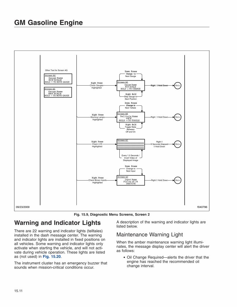
Warning and Indicator LightsThere are 22 warning and indicator lights (telltales)installed in the dash message center. The warningand indicator lights are installed in fixed positions onall vehicles. Some warning and indicator lights onlyactivate when starting the vehicle, and will not acti-vate during vehicle operation. These lights are listedas (not used) in Fig. 15.20.
The instrument cluster has an emergency buzzer thatsounds when mission-critical conditions occur.
A description of the warning and indicator lights arelisted below.
Maintenance Warning LightWhen the amber maintenance warning light illumi-nates, the message display center will alert the driveras follows:
• Oil Change Required—alerts the driver that theengine has reached the recommended oilchange interval.
Down PressChange to
Next Gauge
Right HoldStep Gauge toNext Position
Right || Hold Down
Down PressChange to
Next Telltale
Right HoldToggle State
BetweenOff and On
Right || Hold Down
Every 1.5 Seconds /Invert Video of
Displayed Image
Right ||9 Seconds Elapsed
|| Hold Down
Down PressChange toNext Input
Right || Hold Down
Right PressCheck Gauges
Highlighted
Right PressWarning Lamps
Highlighted
Right PressCheck LCDHighlighted
Right PressCheck Binary Inputs
Highlighted
Menu
Menu
Menu
Menu
Other Text for Screen AG
09/23/2009 f040796
Fig. 15.9, Diagnostic Menu Screens, Screen 2
GM Gasoline Engine
15.11

• Air Filter Reminder—the air filter requireschecking or replacement.
• Transmission Prognostics Warning—if thetransmission has prognostics enabled.
Left-Turn Signal ArrowThe green left-turn signal arrow flashes on and offwhenever the outside left-turn signal lights are flash-ing.
Both turn signal arrows flash when the hazard warn-ing flasher is turned on.
Check Engine IndicatorThe amber check engine indicator light illuminateswhen certain faults are detected. If a critical enginecondition exists (for example, low oil pressure or highcoolant temperature), the check engine light will illu-minate to alert the driver to correct the condition assoon as possible. If the condition gets worse, thestop engine light will illuminate.
NOTE: If the check engine light illuminates dur-ing vehicle operation, take the vehicle directly toan authorized Freightliner service facility.
Stop Engine WarningThe red stop engine warning light illuminates to indi-cate that the protection system available for the en-gine has been activated. The engine ECU will deratethe engine, allowing it to run, but at lower rpm andslower vehicle speed. The vehicle may be driven to asafe location.
NOTICEBecause operating the engine when the red stopengine light is illuminated can lead to severe en-gine damage, the driver must move the vehicle toa safe location as quickly as possible and shutdown the engine.
02/06/2012 f040797
AUXILIARYSCREENS
SOFTWARE VER: x.yyCONFIG: cccccccHARDWARE VER: z
Right || Hold DownRight Press
Version InformationHighlighted
Menu
Screen AM
Input NamePin pp of 26xx.x Units
Down PressChange toNext Input
Right || Hold Down
ECUs on Data BusJ1939 SA xxJ1939 SA yy
Down PressScroll ScreenDown 1 Line
Right || Hold Down
Right PressCheck Analog Inputs
Highlighted
Right PressCheck Data Link
Highlighted
Menu
Menu
Screen AK
Screen AL
Fig. 15.10, Diagnostic Menu Screens, Screen 3
GM Gasoline Engine
15.12

If the engine is shut down while the vehicle is in ser-vice, a single restart attempt may be performed. De-pending on the nature of the fault condition, a cool-down period may be required before restarting. If,upon restarting, the fault condition still exists the
lamp will come on and the engine should be shutdown. At this point, the vehicle is unsafe to drive andshould be transported to an authorized Freightlinerservice facility.
H*
SELF TEST
DISPLAY MESSAGES
WARNING MESSAGES
Active WarningMessages
No Warnings Active orAll Warnings
Acknowledged
Right HoldPark Brake On
IGNITION ON
IGNITIONOFF
IgnitionOff
Ignition On orHeadlamps On or
Marker Lamps On orPark Brake Off
IgnitionOn
Ignition Off &Headlamps Off &
Marker Lamps Off &Park Brake On
Self TestEnabled
AUXILIARYSCREENS
ACTIVE
Ignition Off &( Headlamps On or
Marker Lamps On orPark Brake Off )
Ignition On
USB Drive Present &Park Brake On &
Vehicle Speed = 0 &Not in Self Test
H*
NORMAL MODE
DOWNLOADMODE
09/23/2009 f040788
Fig. 15.11, Ignition On, Normal Mode
GM Gasoline Engine
15.13

IMPORTANT: Do not attempt to restart the en-gine while the vehicle is moving. Bring the ve-hicle to a safe stop and restart the engine withthe vehicle stopped.
Malfunction Indicator Lamp (MIL)Indicates an engine emissions-related fault. See theengine operation manual for details.
Low Air Pressure WarningThe red low air pressure warning light and emer-gency buzzer activate when the engine is turned onif air pressure in the primary or secondary air reser-voir is below 65 to 75 psi (448 to 517 kPa), and re-
main on until air pressure rises above that level inboth reservoirs.
The warning light and buzzer also activate duringoperation whenever air pressure in the primary orsecondary air reservoir falls below 65 to 75 psi (448to 517 kPa).
Wait to Start IndicatorThe amber wait to start indicator light illuminates withthe ignition switch in the ON position prior to enginestart-up. Do not crank the engine until the wait tostart indicator light goes out.
SELF TEST
DISPLAY MESSAGES
XXXXXXXXXXXXXXXXXXXXXXXXXXXXXXXXXXXXXXXXXXXXXXXXXXXXXXXXXXXXXXXXXX
XXXXXXXXXXXXXXXXXXXXXXXXXXXXXXXXXXXXXXXXXXXXXXXXXXXXXXXXXXXXXXXXXX
Screen Displayedfor 1.5 Seconds
Screen Displayedfor 1.5 Seconds
Startup Screen Enabled
The Self Test screens display the FCCClogo in normal video (Screen A) and in
reverse video (Screen B)
Startup Screen Disabled
Screen A
Screen B
02/06/2012 f040789
Fig. 15.12, Self Test
GM Gasoline Engine
15.14

ABS IndicatorThe amber antilock brake system (ABS) indicatorlight illuminates when there is a malfunction in thevehicle ABS.
NOTE: For more information about this light andthe ABS system, see Chapter 7.
Shift Inhibit IndicatorThe amber shift inhibit indicator light illuminateswhenever all conditions for safe transmission shiftinghave not been met.
Check Transmission IndicatorThe amber check transmission indicator illuminateswhen the temperature of the transmission fluid goesabove the preset level set by the transmission manu-facturer.
For more information, see the transmission manufac-turer’s manual provided with the vehicle.
Stop Transmission IndicatorThe red warning light illuminates when the transmis-sion control unit senses a malfunction.
Right-Turn Signal ArrowThe green right-turn signal arrow flashes on and offwhenever the outside right-turn signal lights areflashing.
Both turn signal arrows flash when the hazard warn-ing flasher is turned on.
Fasten Seat Belts WarningThe red fasten seat belts warning light (seat belticon) illuminates for 15 seconds after the ignitionswitch is turned on.
DISPLAY MESSAGES
Selected Line 1 DataSelected Line 2 DataSelected Line 3 Data
Favorites Display MenuAverage Fuel EconomyGear Attained Status
Right Press Highlight First Item in List
Down PressMove to, and Highlight,
Next Item in List
Right PressPut Data For Highlighted ItemIn Display Line CurrentLine
Down HoldMake No Changes
Down Press Highlight CurrentLine
HighlightTimer = 5 sec.
WARNING MESSAGES
AUXILIARY SCREENS
New WarningMessage Active
Right HoldPark Brake On
HighlightTimer = 0
Right Hold Reset Highlighted Item
(if resettable)
Screen C Screen D
11/23/2011 f040790
Fig. 15.13, Display Messages
GM Gasoline Engine
15.15

Hydraulic Brake System WarningThe red brake system warning light illuminates ifthere is a hydraulic brake system failure, or if the ve-hicle is powered and the engine is not running.
Headlight High-Beam IndicatorThe blue high-beam indicator light (sideways beamicon) illuminates when the headlight high beams areon.
Brake System Warning/Parking BrakeOn IndicatorThe red brake system warning/parking brake on indi-cator light activates whenever the parking brake isengaged.
If the vehicle is moving at a speed of 2 mph (3 km/h)or more, the emergency buzzer will sound until theparking brake is released.
AUXILIARY SCREENS
SETUP MAINTENANCE DIAGNOSTICS
Down PressHighlight next
line of list.At middle,wrap to top
MAINTENANCE
DIAGNOSTICS
Right PressSetup
highlighted
Right PressDiagnosticshighlighted
Right PressMaintenancehighlighted
SETUP
SETUP.
DISPLAYMESSAGES
Down Hold
TRIP DATARight Press
Trip Datahighlighted
Screen G
02/06/2012 f040791
Fig. 15.14, Auxiliary Screens
GM Gasoline Engine
15.16
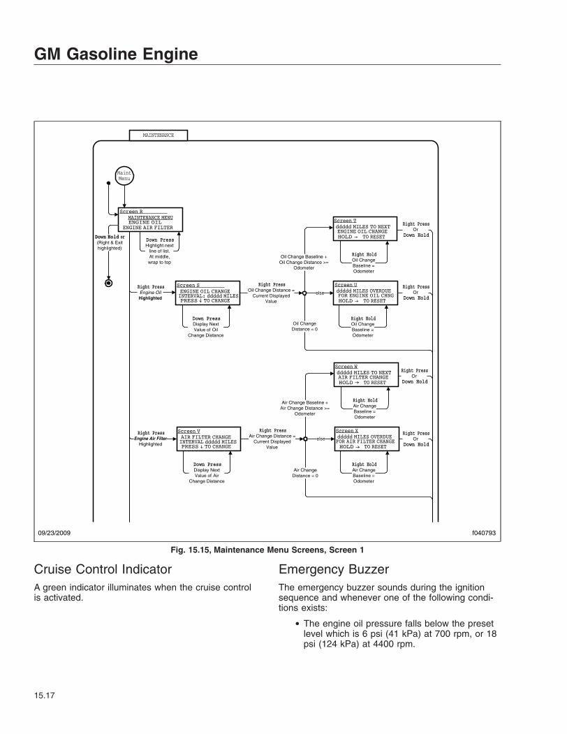
Cruise Control IndicatorA green indicator illuminates when the cruise controlis activated.
Emergency BuzzerThe emergency buzzer sounds during the ignitionsequence and whenever one of the following condi-tions exists:
• The engine oil pressure falls below the presetlevel which is 6 psi (41 kPa) at 700 rpm, or 18psi (124 kPa) at 4400 rpm.
MAINTENANCE
(Right & Exithighlighted)
Right PressEngine OilHighlighted
Right PressEngine Air Filter
Highlighted
Down PressHighlight next
line of list.At middle,wrap to top
MaintMenu
Down PressDisplay NextValue of Air
Change Distance
Air Change Baseline +Air Change Distance >=
Odometer
Air ChangeDistance = 0
else
Right PressAir Change Distance =
Current DisplayedValue
Right HoldAir ChangeBaseline =Odometer
Right HoldAir ChangeBaseline =Odometer
Right PressOr
Down Hold
Right PressOr
Down Hold
Down PressDisplay NextValue of Oil
Change Distance
Oil Change Baseline +Oil Change Distance >=
Odometer
else
Right PressOil Change Distance =
Current DisplayedValue
Right HoldOil ChangeBaseline =Odometer
Right HoldOil ChangeBaseline =Odometer
Right PressOr
Down Hold
Right PressOr
Down Hold
Oil ChangeDistance = 0
09/23/2009 f040793
Fig. 15.15, Maintenance Menu Screens, Screen 1
GM Gasoline Engine
15.17

• The air pressure falls below the preset level,which is 65 psi (448 kPa).
• The parking brake is set with the vehicle mov-ing at a speed greater than 2 mph (3 km/h).
• The coolant temperature rises above 253°F(123°C) and the check engine and stop enginelights illuminate. When the coolant temperaturefalls below 244° (118°C) the emergency buzzerand stop engine light will turn off.
NOTE: The check engine light will remain onuntil the vehicle is inspected at an authorizedFreightliner service facility.
Speedometer and TachometerSpeedometerThree kinds of speedometer faces are available. TheU.S. version of the speedometer registers speed inboth miles per hour (mph) and kilometers per hour(km/h), with mph in larger numbers. See Fig. 15.21.
The NAFTA version (not shown) of the speedometerface reverses this arrangement, with km/h in largernumbers. The metric-only version (not shown) showskm/h exclusively.
TachometerThe tachometer indicates engine speed in revolutionsper minute (rpm) and serves as a guide for shiftingthe transmission and keeping the engine in the ap-propriate rpm range. See Fig. 15.21.
Standard InstrumentsFuel Level GaugeThe fuel level gauge indicates the level of fuel in thefuel tanks. See Fig. 15.22. A low-level warning lightilluminates when the diesel fuel level registers 1/8thof capacity.
02/06/2012 f040794
AUXILIARYSCREENS
Right HoldSend SPN 1584 = 39
Right PressTransmission
Oil LifeHighlighted
Right PressTransmission
Oil FilterHighlighted
Right PressOr
Down Hold
Right PressOr
Down Hold
Right PressOr
Down Hold
MaintMenu
Right HoldSend SPN 1584 = 37
Right PressOr
Down Hold
Fig. 15.16, Maintenance Menu Screens, Screen 2
GM Gasoline Engine
15.18

Engine Oil Pressure Gauge
NOTICEA sudden decrease or absence of oil pressuremay indicate mechanical failure. Bring the vehicleto a safe stop and investigate the cause to pre-vent further damage. Do not operate the engineuntil the cause has been determined and cor-rected.
If the engine oil pressure falls below preset levels,the check engine light will illuminate. If the conditiondoes not improve, the CHECK engine light and lowoil pressure warning light will also illuminate and thebuzzer will sound. See Fig. 15.23. At this point, theengine will derate or shut down, depending on thetype of engine protection system installed.
Trip Data
AUXILIARYSCREENS
Note 6:Screen AO scrolls to display the following items:
Trip TimeIdle TimeMax RPMAvg RPMMax SpeedAvg SpeedAvg Fuel EconomyReset AllExit
Right PressReset AllHighlighted
Correct Passcode /Reset Trip
Data
Right Press
Down PressHighlight next
line of list.At bottom,wrap to top
(Right & Exithighlighted)
Wrong Passcode /Down Press
Right Press
09/23/2009 f040798
Fig. 15.17, Trip Data
GM Gasoline Engine
15.19

Coolant Temperature Gauge
NOTICEA sudden increase in coolant temperature mayindicate engine or cooling system failure. Bringthe vehicle to a safe stop and investigate thecause to prevent further damage. Do not operatethe engine until the cause has been determinedand corrected.
During normal engine operation, the coolant tem-perature gauge should read 200 to 205°F (93 to96°C). See Fig. 15.24. If the temperature remainsbelow 160°F (71°C) or exceeds 235°F (113°C), in-spect the cooling system to determine the cause.See the vehicle workshop manual for troubleshootingand repair procedures.
The coolant temperature gauge is very important.See Fig. 15.24. If the coolant temperature risesabove 253°F (123°C), the check engine and stopengine lights will illuminate, and the buzzer willsound. At this point, the engine will derate and idle
speed will increase, to speed up the cooling fan andwater pump to cool the engine.
02/06/2012 f040799
WARNING MESSAGES
DISPLAY MESSAGES
H*
WARNING Warning Message
No WarningMessages in List /
Msg Displayed for 5 Sec. /Display Next Entry in
Warning Message List
Any Button Press
/Display 1st Message
in WarningMessage List
Screen AN
Fig. 15.18, Warning Messages
GM Gasoline Engine
15.20

IGNITION OFF
Park Brake On
Park Brake On
Park Brake Off
IGNITIONON
Headlamps Off &Marker Lamps Off &
Park Brake On
Ignition On
02/06/2012 f040800
Fig. 15.19, Ignition Off (shown when ignition is keyed OFF)
GM Gasoline Engine
15.21

10/24/2014 f611241a
1
2
3 4 5 6 7 8 9 10 11 12 13 14
15
16
1718
19
20 21
22
UNLEADED FUEL ONLY
1. Maintenance Warning Light2. Left-Turn Signal Arrow3. High Exhaust System
Temperature (HEST) Lamp (notused)
4. Check Engine Indicator5. Stop Engine Warning6. Malfunction Indicator Lamp (MIL)7. Engine Brake Light (not used)
8. Low Air Pressure Warning9. Wait to Start Indicator10. ABS Indicator11. Shift Inhibit Indicator12. Check Transmission Indicator13. Stop Transmission Indicator14. Diesel Particulate Filter (DPF)
Lamp (not used)15. Right-Turn Signal Arrow
16. Fasten Seat Belts Warning17. Hydraulic Brake System Warning18. Headlight High-Beam Indicator19. Traction Control Indicator (not
used)20. Parking Brake On Indicator21. Cruise Control Indicator22. Auxiliary Power Generator (not
used)
Fig. 15.20, Gasoline Engine Warning and Indicator Lights
07/22/2014 f611239
1 2
1. Tachometer (optional) 2. Speedometer
Fig. 15.21, Speedometer and Tachometer (U.S. version)
GM Gasoline Engine
15.22

10/27/2014 f611236a
1
UNLEADED FUEL ONLY
1. Low Fuel Level Warning Light
Fig. 15.22, Fuel Level Gauge (typical gauge shown)
07/21/2014 f611237
1
1. Low Oil Pressure Warning Light
Fig. 15.23, Engine Oil Pressure Gauge
07/21/2014 f611238
1
1. High Coolant Temperature Warning Light
Fig. 15.24, Coolant Temperature Gauge
GM Gasoline Engine
15.23
16
Hydraulic HybridSafety Precautions . . . . . . . . . . . . . . . . . . . . . . . . . . . . . . . . . . . . . . . . . . . . . . . . . . . . . . . . . . . . . . . 16.1Hydraulic Hybrid Drive System . . . . . . . . . . . . . . . . . . . . . . . . . . . . . . . . . . . . . . . . . . . . . . . . . . . . . 16.2Hydraulic Gauges, Warning Indicators, and Message Displays . . . . . . . . . . . . . . . . . . . . . . . . . . . . 16.6Transmission Shift Pad . . . . . . . . . . . . . . . . . . . . . . . . . . . . . . . . . . . . . . . . . . . . . . . . . . . . . . . . . . 16.12Pretrip Inspection . . . . . . . . . . . . . . . . . . . . . . . . . . . . . . . . . . . . . . . . . . . . . . . . . . . . . . . . . . . . . . . 16.12Engine Starting and Shutdown . . . . . . . . . . . . . . . . . . . . . . . . . . . . . . . . . . . . . . . . . . . . . . . . . . . . 16.15Driving the Vehicle . . . . . . . . . . . . . . . . . . . . . . . . . . . . . . . . . . . . . . . . . . . . . . . . . . . . . . . . . . . . . . 16.17Safety Features . . . . . . . . . . . . . . . . . . . . . . . . . . . . . . . . . . . . . . . . . . . . . . . . . . . . . . . . . . . . . . . . 16.18Jumpstarting and Towing . . . . . . . . . . . . . . . . . . . . . . . . . . . . . . . . . . . . . . . . . . . . . . . . . . . . . . . . . 16.20Emergency Procedures . . . . . . . . . . . . . . . . . . . . . . . . . . . . . . . . . . . . . . . . . . . . . . . . . . . . . . . . . . 16.20

Safety PrecautionsTo ensure the safety of the driver, read and under-stand the statements that follow before operating thehydraulic hybrid vehicle.
DANGERWarning labels are placed on various compo-nents of the hydraulic hybrid drive system. Fail-ure to read and follow the directions given canlead to personal injury, loss of life, and vehicle orcomponent damage.
Never run hands, arms, or any other part of thebody over a hydraulic hose, line, fitting, or as-sembly to check for leaks. A pinhole leak can re-lease toxic fluid at more than 600 ft (183 m) persecond, acting as a hypodermic needle and pen-etrating both protective clothing and skin at shortdistances.
Never tighten or loosen a hydraulic connectionwhen the system is under pressure. The connec-tion could fail catastrophically, causing personalinjury and/or damage to the vehicle. Make certainthat all high pressure is bled from the hydraulicsystem before working on any connections.
Use extreme caution when working with hydrau-lic hoses, lines, fittings, or assemblies during in-stallation, preventive maintenance, or componentreplacement. Fluids under high pressure can bedangerous and potentially lethal. Make sure tobleed all high pressure so that hoses and compo-nents can be examined safely.
Discharging high pressure using the manualbleed valve does not release the nitrogen gasprecharge pressure within the accumulator. Thenitrogen is under high pressure and can be dan-gerous and potentially lethal if the accumulator ispunctured.
It takes approximately 10 minutes for high-pressure fluid to discharge once the manualbleed valve has been opened. Do not attempt towork on the hybrid drive system until there isverification that the high-pressure fluid has beenfully discharged.
Do not exit the vehicle before applying the parkbrake and shifting the transmission to neutral(N). Otherwise, the vehicle could roll, causingproperty damage, personal injury, or loss of life.
Failure or improper selection or use of hoses,tubing, fittings, assemblies, or related accesso-ries can cause death, personal injury, and prop-erty damage. Possible consequences of failure orimproper selection or use of these items includebut are not limited to the following:
• Fittings thrown off at high speed.
• High velocity fluid discharge.
• Explosion or burning of the discharged fluid.
• Contact with suddenly moving or falling objectsthat are controlled by the discharged fluid.
• Injection by high-pressure fluid discharge.
• Contact with discharged fluids that may causeinjury due to heat, cold, or toxicity.
• Electrocution from electric power lines.
• Whipping hoses.
• Sparking or explosion caused by static electric-ity buildup or other sources of electricity.
• Sparking or explosion while spraying paint orflammable liquids.
• Injuries resulting from inhalation, ingestion, orexposure to fluids.
NOTICEWhen the red stop transmission indicator illumi-nates, the transmission control module (TCM) orhybrid control module (HCM) senses a malfunc-tion in the hydraulic hybrid drive system and themessage center will display STOP TRANS and/orSTOP HYBRID. The vehicle will shut down imme-diately, in order to avoid damaging the hydraulichybrid system.
If the low pressure reservoir (LPR) fluid level isnot even with or higher than the LOW indicatormarks on the sight glass, do not start the vehicle.LPR pressure should be between 35 to 70 psi(241 to 483 kPa). Operating the vehicle with a lowLPR fluid level will result in damage to the hy-draulic hybrid system.
Remove the rear driveshaft before towing a ve-hicle equipped with the hydraulic hybrid drivesystem. Failure to do so will result in damage tothe hybrid drive system. Once the driveshaft hasbeen removed, do not attempt to start a vehicle
Hydraulic Hybrid
16.1

equipped with a hydraulic hybrid drive system.Doing so will damage the hydraulic hybrid sys-tem components.
NOTE: It is normal for the engine to continuerunning for up to 30 minutes after charging iscomplete, as certain parameters must be metbefore the hydraulic hybrid system can shut theengine off.
If the message SHIFT TO NEUTRAL OR PARKappears on the message display screen (withan audible chime) and the park brake engagesautomatically, the driver’s seat belt is unbuckled.Fasten the driver’s seat belt to release the parkbrake.
If the gear selection continuously flashes on theshift pad display, along with the shift inhibitwarning indicator illuminated (with an audiblechime) and the message center display screenshowing SHIFT INHIBIT, the vehicle is in coldweather startup or slow charge mode and willnot shift into drive (D) or reverse (R) until thehybrid drive system is at the proper operatingtemperature. Gear selection will be allowedonce the warning indicator is no longer illumi-nated and the message does not appear on themessage display screen.
SHIFT INHIBIT will also appear on the messagecenter display screen if an attempt is made toshift the transmission from drive (D) to reverse(R) or from reverse (R) to drive (D) and vehiclespeed is 5 mph (8 km/h) or higher. If this oc-curs, the hydraulic hybrid system will shift thetransmission into neutral (N) and N will appearas the current gear on the shift pad. The SHIFTINHIBIT message will appear on the messagedisplay center and the shift inhibit indicator willilluminate. The selected gear will continue toflash on the shift pad until the previous gear orneutral (N) is selected. The message and theindicator will turn off and the transmission shiftwill be allowed when vehicle speed is less than5 mph (8 km/h).
Hydraulic Hybrid Drive SystemVehicles equipped with the hydraulic hybrid drivesystem can be identified by the access hole on thedriver’s side of the vehicle, shown in Figure 16.1.Some units may have a door to cover the accesshole. This opening allows the driver to view the LPRpressure gauge and fluid level sight glass.
Hydraulic hybrid vehicles also utilize a hybrid perfor-mance gauge and an accumulator state-of-charge(SOC) gauge, both of which are located in the instru-ment cluster.
Functional DifferencesThe hydraulic hybrid drive system operates similarlyto a conventional drivetrain in that to move the ve-hicle, the proper gear is selected and the acceleratorpedal is pressed, and to stop the vehicle, the brakepedal is pressed. However, the hydraulic hybrid drivesystem is different in the following ways:
• It utilizes hydraulic pressure to propel the ve-hicle at speeds up to 25–30 mph (40–48 km/h).
• Only after the vehicle reaches a speed above25–30 mph (40–48 km/h), is the engine me-chanically coupled to the rear differential.
• It captures the initial kinetic energy obtainedduring braking to pressurize the hydraulic sys-tem, storing the energy in the accumulator.
• Braking is a combination of brake energy re-covery and the friction brakes. A small transi-tion from brake energy recovery mode to fric-tion braking may be when braking.
• The engine will run at a varying rpm, indepen-dent of vehicle speed, in order to run the pri-mary pump and pressurize the accumulator.This allows for the most efficient operation ofthe engine.
• It can be used to start the engine while the ve-hicle is stopped or is in motion.
• The engine can be shut off while the vehicle isstopped or in motion, and remain off duringvehicle operation, up to 25–30 mph (40–48km/h).
• If adequate energy is in the high pressure ac-cumulator and all requirements are met, it will
Hydraulic Hybrid
16.2
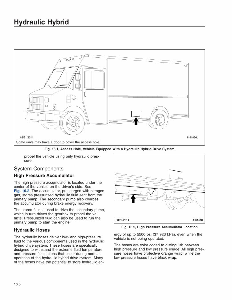
propel the vehicle using only hydraulic pres-sure.
System ComponentsHigh Pressure AccumulatorThe high pressure accumulator is located under thecenter of the vehicle on the driver’s side. SeeFig. 16.2. The accumulator, precharged with nitrogengas, stores pressurized hydraulic fluid sent from theprimary pump. The secondary pump also chargesthe accumulator during brake energy recovery.
The stored fluid is used to drive the secondary pump,which in turn drives the gearbox to propel the ve-hicle. Pressurized fluid can also be used to run theprimary pump to start the engine.
Hydraulic HosesThe hydraulic hoses deliver low- and high-pressurefluid to the various components used in the hydraulichybrid drive system. These hoses are specificallydesigned to withstand the extreme fluid temperatureand pressure fluctuations that occur during normaloperation of the hydraulic hybrid drive system. Manyof the hoses have the potential to store hydraulic en-
ergy of up to 5500 psi (37 923 kPa), even when thevehicle is not being operated.
The hoses are color coded to distinguish betweenhigh pressure and low pressure usage. All high pres-sure hoses have protective orange wrap, while thelow pressure hoses have black wrap.
03/21/2011 f151096b
Some units may have a door to cover the access hole.
Fig. 16.1, Access Hole, Vehicle Equipped With a Hydraulic Hybrid Drive System
03/22/2011 f261410
Fig. 16.2, High Pressure Accumulator Location
Hydraulic Hybrid
16.3

Low Pressure Reservoir (LPR)The LPR is located under the center of the vehicleon the driver’s side, and is visible through the bodyopening. See Fig. 16.3. The LPR is precharged withnitrogen and stores hydraulic fluid.
A sight glass mounted on the side of the LPR con-tains markings used to determine the fluid level. Thepressure gauge is used to determine nitrogen gaspressure in the LPR. See Fig. 16.4.
GearboxThe gearbox, shown in Fig. 16.5, transfers powerfrom the engine and/or the secondary pump out tothe rear wheels. The gearbox can also use thepower output of the primary pump to start the engine.
Gearbox Fluid FilterThe gearbox fluid filter, shown in Fig. 16.6, removescontaminates that occur normally as a result of theheat and friction generated by the movement of theinternal components in the gearbox. Removing theseparticles allows the fluid to lubricate and cool thecomponents, preventing premature wear and poten-tial damage.
Gear PumpThe gear pump is mounted on the back of the gear-box and is driven by the engine. See Fig. 16.7. Itcirculates hydraulic fluid through the system coolingand filtration loop, and gearbox fluid through thegearbox filtration loop.
Primary and Secondary High PressurePumpsThe primary and secondary high pressure pumps aremounted on the front of the gearbox as shown inFig. 16.8.
The primary pump is used either as a pump ormotor. In pumping mode, the pump is driven by the
03/22/2011 f261411
Fig. 16.3, Location of the LPR
03/22/2011 f261412
1
2
1. Pressure Gauge 2. Sight Glass
Fig. 16.4, LPR Sight Glass and Pressure Gauge
03/22/2011 f261414
Fig. 16.5, Gearbox
Hydraulic Hybrid
16.4
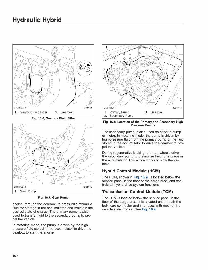
engine, through the gearbox, to pressurize hydraulicfluid for storage in the accumulator, and maintain thedesired state-of-charge. The primary pump is alsoused to transfer fluid to the secondary pump to pro-pel the vehicle.
In motoring mode, the pump is driven by the high-pressure fluid stored in the accumulator to drive thegearbox to start the engine.
The secondary pump is also used as either a pumpor motor. In motoring mode, the pump is driven byhigh-pressure fluid from the primary pump or the fluidstored in the accumulator to drive the gearbox to pro-pel the vehicle.
During regenerative braking, the rear wheels drivethe secondary pump to pressurize fluid for storage inthe accumulator. This action works to slow the ve-hicle.
Hybrid Control Module (HCM)The HCM, shown in Fig. 16.9, is located below theservice panel in the floor of the cargo area, and con-trols all hybrid drive system functions.
Transmission Control Module (TCM)The TCM is located below the service panel in thefloor of the cargo area. It is situated underneath thebulkhead connector and interfaces with most of thevehicle’s electronics. See Fig. 16.9.
03/22/2011 f261415
1
2
1. Gearbox Fluid Filter 2. Gearbox
Fig. 16.6, Gearbox Fluid Filter
03/31/2011 f261416
1
1. Gear Pump
Fig. 16.7, Gear Pump
04/04/2011 f261417
1
2
3
1. Primary Pump2. Secondary Pump
3. Gearbox
Fig. 16.8, Location of the Primary and Secondary HighPressure Pumps
Hydraulic Hybrid
16.5

Hydraulic Gauges, WarningIndicators, and MessageDisplaysGaugesThe hybrid performance gauge and the state-of-charge (SOC) gauge are two hydraulic hybrid systemgauges located in the instrument panel. SeeFig. 16.10.
Hybrid Performance GaugeThe hybrid performance gauge displays how effi-ciently the vehicle is being driven. The green ECONarea, which is the target range, represents when thevehicle is operating in the most economical range.When normal acceleration and braking occur, brakeenergy recovery maintains a high state-of-charge inthe accumulator for maximum hydraulic hybrid driveperformance.
The red BRAKE area indicates an aggressive brak-ing occurrence. Aggressive braking uses more fric-tion braking than regenerative braking to slow thevehicle, which results in less energy captured forstorage in the accumulator.
The red ACCEL area indicates when the acceleratoris fully depressed, which depletes the energy stored
in the accumulator in two ways. First, the enginewould restart sooner than normal, and reduce theamount of engine-off time. Second, if the engine isalready running, the engine’s energy is used in aless efficient manner to further accelerate the ve-hicle.
If the hybrid performance gauge does not remainwithin the ECON area, regardless of how efficientlythe brakes or accelerator are applied during opera-tion, contact a certified hydraulic hybrid drive servicetechnician to determine if there is a problem with thegauge or the system.
State-of-Charge (SOC) GaugeThe SOC gauge displays the available fluid pressure(energy) in the accumulator for use by the hydraulichybrid drive system.
Slower vehicle speeds require less energy use bythe hydraulic hybrid drive system to propel the ve-hicle, allowing it to maintain a higher percentage ofstored fluid pressure in the accumulator.
The state-of-charge can also be maintained throughnormal braking, where brake energy recovery is en-abled, allowing the rear wheels to drive the second-ary pump to pressurize the accumulator. Light tomoderate braking will increase the state-of-chargemore for a given event.
The higher the state-of-charge, the more energythere is to propel the vehicle with the hydraulic hybriddrive system rather than the engine. This results infuel savings and less wear on the engine.
The state-of-charge can also be increased by ag-gressive acceleration. However, this type of increasein the state-of-charge will decrease fuel economyand should be avoided.
If the percentage on the gauge remains in the redarea regardless of how efficiently the vehicle is oper-ated, contact a certified hydraulic hybrid drive servicetechnician to determine if there is a problem with thegauge or the system.
Warning and Indicator LightsThe warning and indicator lights are located in theinstrument panel and contain all of the standard andoptional warning and indicator lights. See Fig. 16.11.When the ignition is turned to the ON position, allindicators will illuminate for a required self-test.
04/15/2011 f2614181 2 3
1. Transmission Control Module2. Bulkhead Connectors3. Hybrid Control Module
Fig. 16.9, Floor Panel Access
Hydraulic Hybrid
16.6

The hydraulic hybrid vehicle also has unique indica-tors that are specific to the hydraulic system. Theseare the propulsion system ready and low traction in-dicators, which are described later in this section.
If an indicator—not including the READY indicator—remains illuminated after the self-test or illuminateswhile the vehicle is in operation, a fault exits in thesystem. A warning chime will sound to alert the driverwhen an indicator is illuminated.
Check Transmission and StopTransmission IndicatorsThe amber check transmission indicator illuminateswhen a problem is detected in the hydraulic hybriddrive system. See Fig. 16.11.
If the check transmission indicator illuminates, alongwith the message center displaying CHECK TRANSor CHECK HYBRID, have the vehicle serviced assoon as possible by a certified hydraulic hybrid driveservice technician.
09/22/2011 f611053a
1 2
9
3
7
10
8 6
4
5
HYBRIDPERFORMANCE
1. Hybrid Performance Gauge2. Speedometer3. State-of-Charge Gauge4. Toggle Button, Right5. Toggle Button, Down
6. Coolant Temperature Gauge7. Message Display Center8. Engine Oil Pressure Gauge9. Diesel Exhaust Fluid (DEF) Gauge10. Fuel Gauge
Fig. 16.10, Typical Ametek Instrument Panel (Hydraulic Hybrid), EPA10 and Newer Engines
Hydraulic Hybrid
16.7

NOTICEWhen the red stop transmission indicator illumi-nates, the transmission control module (TCM) orhybrid control module (HCM) senses a malfunc-tion in the hydraulic hybrid drive system and themessage center will display STOP TRANS and/orSTOP HYBRID. The vehicle will shut down imme-diately, in order to avoid damaging the hydraulichybrid system. See Fig. 16.11 for an example ofthe stop transmission indicator.
When the red stop transmission indicator illuminates,the transmission control unit senses a malfunction inthe hydraulic hybrid drive system. The vehicle willshut down immediately, in order to avoid damagingthe hydraulic hybrid system.
Propulsion System Ready IndicatorNOTE: In order for the hydraulic hybrid systemto power the vehicle, the propulsion systemmust be charged. If the propulsion system is notcharged, the engine can be used to charge thesystem and power the vehicle.
The green propulsion system ready indicator will illu-minate when the hydraulic hybrid drive system isready to propel the vehicle. When the ignition isturned to the ON position, and the propulsion systemready indicator is illuminated, the vehicle can bedriven with the engine off. See Fig. 16.11 for an ex-ample of the propulsion system ready indicator.
NOTE: To start the engine with the ready indica-tor illuminated, to heat the cab for example, turnthe ignition to the START position and hold it forat least five seconds.
09/22/2011 f611126
1
2
3 4 5 6 7 8 9 10 11 12 13
14
15
2122
17 18
16
20
19
HYBRIDPERFORMANCE
1. Maintenance Warning Light2. Left-Turn Signal Arrow3. High Exhaust System
Temperature (HEST) Lamp4. Check Engine Indicator5. Stop Engine Warning6. Malfunction Indicator Lamp7. Engine Brake Light8. Wait to Start Warning Light9. ABS Indicator
10. Shift Inhibit Indicator11. Check Transmission Indicator12. Stop Transmission Indicator13. Diesel Particulate Filter (DPF)
Lamp14. Right-Turn Signal Arrow15. Fasten Seat Belt Warning16. Air Brake Indicator (low air
warning)
17. Hydraulic Brake System Warning18. Headlight High-Beam Indicator19. Low Traction Control Indicator20. Parking Brake On Indicator21. Cruise Control Indicator22. Propulsion System Ready
Indicator
Fig. 16.11, Warning Lights, Hydraulic Hybrid Vehicle
Hydraulic Hybrid
16.8

If the propulsion system ready indicator does not illu-minate, the message START ENGINE will appear onthe message display screen and the hydraulic hybridsystem will not allow the transmission to shift untilthe system is charged. To charge the system, theengine must be running in order to drive the primarypump to pressurize fluid in the high pressure accu-mulator. Turn the ignition to the START position tostart the engine. When the engine starts, WAIT willappear in the message display screen. The WAITmessage will disappear and the propulsion systemready indicator will illuminate once the charging pro-cess is complete. The engine will turn off as long asthe engine coolant is at the proper operating tem-perature.
Shift Inhibit IndicatorThe amber shift inhibit indicator illuminates wheneverall conditions for safe transmission shifting have notbeen met. SHIFT INHIBIT will also appear in themessage display screen when the indicator illumi-nates. See Fig. 16.11 for an example of the shift in-hibit indicator. The shift inhibit indicator will illuminatedue to one or more of the following conditions:
• The propulsion system ready indicator is notilluminated.
• The temperature of the hydraulic fluid is lessthan 0°F (–18°C).
• A transmission shift is attempted when the ve-hicle’s speed is above 5 mph (8 km/h). Whenthis occurs, the gearbox will be forced to shiftinto neutral (N) and the current gear will dis-play N on the shift pad. The selected gear willcontinue to flash on the shift pad until eitherthe previous gear or neutral (N) is selected.
The indicator and message will turn off, and thetransmission can be shifted when all of the followingconditions are met:
• The propulsion system ready indicator illumi-nates.
• The temperature of the hydraulic fluid is 0°F(–18°C) or higher.
• Vehicle speed is below 5 mph (8 km/h).
Low Traction Control IndicatorThe amber low traction indicator illuminates whenwheel slippage is detected by the HCM. See
Fig. 16.11 for an example of the low traction controlindicator. LOW TRACTION will appear on the mes-sage display screen. The hybrid system will reducepower output until slippage is no longer detected.
Message DisplaysThe hydraulic hybrid vehicle uses the same instru-ment panel, by Ametek, as the standard dieselWalk-In Van. The panel operates the same way un-less noted otherwise here. See Chapter 2, Instru-ments for a detailed description of the Ametek instru-ment panel.
The following messages can appear on the messagedisplay screen. Brief descriptions for the variousmessages follow.
• low pressure reservoir (LPR) air pressure
• check transmission/check hybrid
• stop transmission/stop hybrid
• hood open
• hybrid communication fault
• hydraulic oil filter monitor
• low traction
• shift to neutral or park
• shift inhibit
• low vehicle battery voltage
Low Pressure Reservoir (LPR) AirPressureLOW LPR AIR PRESSURE will appear on the mes-sage display screen when LPR pressure falls below35 psi (241 kPa) and a warning chime will sound.
Check Transmission/Check HybridA message will appear along with the check trans-mission warning indicator when the transmission con-trol module (TCM) or the hybrid control module(HCM) detects a fault in the hydraulic hybrid system.
When the red stop transmission indicator illuminates,the message center will display STOP TRANS and/orSTOP HYBRID, due to a malfunction in the hydraulichybrid system. The vehicle will shut down immedi-ately, in order to avoid damaging the hydraulic hybridsystem. Contact a certified hydraulic hybrid servicetechnician to determine the corrective action to take.
Hydraulic Hybrid
16.9

NOTICEWhen the red stop transmission indicator illumi-nates, the TCM or HCM senses a malfunction inthe hydraulic hybrid drive system and the mes-sage center will display STOP TRANS and/orSTOP HYBRID. The vehicle will shut down imme-diately, in order to avoid damaging the hydraulichybrid system.
Stop TransmissionIf the TCM or HCM detects a serious fault within thehydraulic hybrid drive system, both the STOPTRANS and STOP HYBRID messages will appearon the message display screen and the stop trans-mission indicator will illuminate. When this occurs,the vehicle will shut down immediately, in order toavoid damaging the hydraulic hybrid system.
Hood OpenThe message HOOD OPEN will appear on the mes-sage display screen and a chime will sound to warnthe driver if the hood is open.
When the engine is off and the hood is open, thehydraulic hybrid system will prevent the engine fromstarting until the hood is closed.
Hybrid Communication FaultIf there is a loss of communication between the HCMand the instrument panel, an HHV COMM FAIL mes-sage will appear on the message display screen.
Hydraulic Oil Filter MonitorWhen the hydraulic fluid filter needs to be changed,REPLACE SYSTEM OIL FILTER will appear on themessage display screen and a chime will sound.
Low TractionWhen wheel slippage is detected by the HCM, LOWTRACTION will appear on the message displayscreen and the amber low traction indicator illumi-nates. The hybrid system will reduce power outputuntil slippage is no longer detected.
Shift to Neutral or ParkThe message SHIFT TO NEUTRAL OR PARK willappear on the message display screen if the driver’sseat belt is unbuckled and the brake pedal is re-
leased while the ignition switch is in the ON position,the engine is OFF, and the vehicle is in drive (D) orreverse (R) and moving less than 1 mph (2 km/h).When these conditions occur, the park brake will au-tomatically engage to prevent the vehicle from acci-dently moving without the driver. A warning chime willsound while the message is displayed.
The park brake will not release until either the engineis started, the ignition is in the OFF position, thedriver’s seat belt is fastened, the brake pedal is de-pressed, or the vehicle is placed in neutral (N). Oncethe park brake is released, the message will disap-pear.
Shift InhibitWhenever all conditions for safe transmission shiftinghave not been met, SHIFT INHIBIT will appear onthe message display screen and the amber shift in-hibit indicator illuminates on the instrument panel.Once the indicator and message turn off, the gear-box will be allowed to shift into the desired gear. Foradditional information, see Shift Inhibit Indicator inthis section.
Low Vehicle Battery VoltageWhen battery voltage is less than or equal to 11.9V,LOW VOLTAGE will appear on the message displayscreen. The message will only be activated if the en-gine rpm has been above 500 rpm for five seconds,or if the engine rpm is 0.
Stop Hybrid
NOTICEWhen the red STOP HYBRID message appears onthe display screen, the TCM or HCM senses amalfunction in the hydraulic hybrid drive system.The vehicle will shut down immediately, in orderto avoid damaging the hydraulic hybrid system.
The message STOP HYBRID will appear on themessage display screen when the hydraulic hybridsystem senses a malfunction. When the messageappears, the vehicle will shut down immediately toavoid damaging the hydraulic hybrid system.
Menu SystemThe hydraulic hybrid drive system has several uniquemenus available. As with the diesel operated Walk-In
Hydraulic Hybrid
16.10

Van, the menu system is shown on the driver displayscreen once the self-test is finished. The menu sys-tem responds to input from the driver and remainsactive as long as the ignition is on. In order for thedriver to operate the menu system, the ignition mustbe ON, and the park brake must be set (ON). Thedriver uses the toggle buttons to move from onemenu screen to another. See Fig. 16.10, Item 4 andItem 5 for the location of the toggle buttons. SeeChapter 2, Instruments for further information onthe Ametek menu system.
The following menus are specific to the hydraulic hy-brid vehicle:
• system oil pressure
• gear attained
• hydraulic oil temperature
• high pressure accumulator (HPA) gas pressure
• low pressure reservoir (LPR)
• transmission temperature
• primary/secondary air tank pressure
• applied air brake pressure 1 and 2
System Oil PressureThe system oil pressure menu shows the hydraulicfluid pressure within the high-pressure accumulator.
Gear AttainedThe gear attained menu lists the selected gear onthe display screen.
Hydraulic Oil TemperatureThe hydraulic oil temperature menu will display thecurrent temperature of the fluid in the hydraulic hy-brid drive system. If the system reaches 170°F(77°C), power output from the hydraulic system isreduced to allow the hydraulic fluid to cool down. Thecheck transmission indicator will illuminate and theCHECK HYBRID message will appear on the displayscreen. The driver should find a safe place to pullover and shut down the vehicle, then contact a certi-fied hydraulic hybrid drive service technician to deter-mine the corrective action to take before proceeding.
NOTICEWhen the red stop transmission indicator illumi-nates, the TCM or HCM senses a malfunction inthe hydraulic hybrid drive system and the mes-sage center will display STOP TRANS and/orSTOP HYBRID. The vehicle will shut down imme-diately, in order to avoid damaging the hydraulichybrid system.
If the hydraulic oil temperature exceeds 180°F(82°C), power output is reduced to zero. The stoptransmission indicator will illuminate and the STOPTRANS or STOP HYBRID message will appear onthe display screen. The vehicle will shut down imme-diately, in order to avoid damaging the hydraulic hy-brid system.
High Pressure Accumulator (HPA) GasPressureThe HPA gas pressure menu will display the nitrogenpressure within the high pressure accumulator.
Low Pressure Reservoir (LPR)The LPR menu will display the nitrogen gas pressurewithin the LPR.
Transmission TemperatureThe transmission temperature menu will display thecurrent temperature of the transmission fluid in thegearbox.
If the temperature exceeds 190°F (88°C), power out-put from the hydraulic system is reduced to allow thefluid in the gearbox to cool down. The check trans-mission indicator will illuminate and the CHECKTRANS message will appear on the display screen.The driver should find a safe place to pull over andshut down the vehicle, then contact a certified hy-draulic hybrid drive service technician to determinethe corrective action to take before proceeding.
NOTICEWhen the red stop transmission indicator illumi-nates, the TCM or HCM senses a malfunction inthe hydraulic hybrid drive system and the mes-sage center will display STOP TRANS and/or
Hydraulic Hybrid
16.11
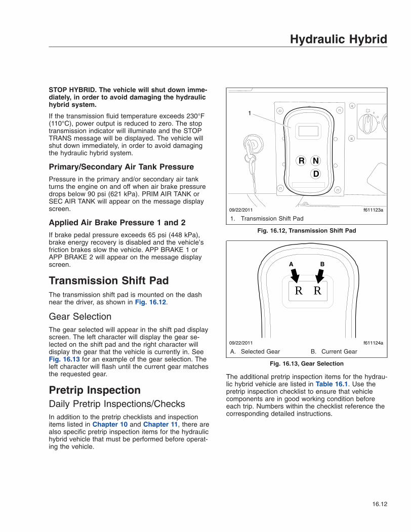
STOP HYBRID. The vehicle will shut down imme-diately, in order to avoid damaging the hydraulichybrid system.
If the transmission fluid temperature exceeds 230°F(110°C), power output is reduced to zero. The stoptransmission indicator will illuminate and the STOPTRANS message will be displayed. The vehicle willshut down immediately, in order to avoid damagingthe hydraulic hybrid system.
Primary/Secondary Air Tank PressurePressure in the primary and/or secondary air tankturns the engine on and off when air brake pressuredrops below 90 psi (621 kPa). PRIM AIR TANK orSEC AIR TANK will appear on the message displayscreen.
Applied Air Brake Pressure 1 and 2If brake pedal pressure exceeds 65 psi (448 kPa),brake energy recovery is disabled and the vehicle’sfriction brakes slow the vehicle. APP BRAKE 1 orAPP BRAKE 2 will appear on the message displayscreen.
Transmission Shift PadThe transmission shift pad is mounted on the dashnear the driver, as shown in Fig. 16.12.
Gear SelectionThe gear selected will appear in the shift pad displayscreen. The left character will display the gear se-lected on the shift pad and the right character willdisplay the gear that the vehicle is currently in. SeeFig. 16.13 for an example of the gear selection. Theleft character will flash until the current gear matchesthe requested gear.
Pretrip InspectionDaily Pretrip Inspections/ChecksIn addition to the pretrip checklists and inspectionitems listed in Chapter 10 and Chapter 11, there arealso specific pretrip inspection items for the hydraulichybrid vehicle that must be performed before operat-ing the vehicle.
The additional pretrip inspection items for the hydrau-lic hybrid vehicle are listed in Table 16.1. Use thepretrip inspection checklist to ensure that vehiclecomponents are in good working condition beforeeach trip. Numbers within the checklist reference thecorresponding detailed instructions.
R N
D
09/22/2011 f611123a
1
1. Transmission Shift Pad
Fig. 16.12, Transmission Shift Pad
09/22/2011 f611124a
R R
A B
A. Selected Gear B. Current Gear
Fig. 16.13, Gear Selection
Hydraulic Hybrid
16.12

Procedure Performed(check off)
Daily Pretrip Inspections/ChecksProcedureReference
Inspect _______ hydraulic system for fluid leaks D1Inspect _______ hydraulic system hose(s) and fitting(s) D2Check _______ LPR fluid level and pressure D3Check _______ active warning indicators D4Check _______ system faults on the message display screen D5
Inspector___________________________________________________ Date ________________
Table 16.1, Hydraulic Hybrid Daily Pretrip Inspection and Maintenance Checklist
NOTE: To help ensure that the hydraulic hybridvehicle delivers safe and reliable service, regu-larly scheduled maintenance must be performedby a certified hydraulic hybrid service technician.
Failure to follow a regular maintenance programwill result in inefficient operation, unscheduleddown-time, and will void the warranty.
Refer to the Walk-In Van Chassis MaintenanceManual for more information concerning mainte-nance intervals and the operations to be per-formed.
Daily Pretrip Inspection andMaintenance Procedures
DANGERWarning labels are placed on various compo-nents of the hydraulic hybrid drive system. Fail-ure to read and follow the directions given canlead to personal injury, loss of life, and vehicle orcomponent damage.
Never run hands, arms, or any other part of thebody over a hydraulic hose, line, fitting, or as-sembly to check for leaks. A pinhole leak can re-lease toxic fluid at more than 600 ft (183 m) persecond, acting as a hypodermic needle and pen-etrating both protective clothing and skin at shortdistances.
Never tighten or loosen a hydraulic connectionwhen the system is under pressure. The connec-tion could fail catastrophically, causing personalinjury and/or damage to the vehicle. Make certainthat all high pressure is bled from the hydraulicsystem before working on any connections.
Use extreme caution when working with hydrau-lic hoses, lines, fittings, or assemblies during in-stallation, preventive maintenance, or componentreplacement. Fluids under high pressure can bedangerous and potentially lethal. Make sure tobleed all high pressure so that hoses and compo-nents can be examined safely.
Discharging high pressure using the manualbleed valve does not release the nitrogen gasprecharge pressure within the accumulator. Thenitrogen is under high pressure and can be dan-gerous and potentially lethal if the accumulator ispunctured.
It takes approximately 10 minutes for high-pressure fluid to discharge once the manualbleed valve has been opened. Do not attempt towork on the hybrid drive system until there isverification that the high-pressure fluid has beenfully discharged.
Do not exit the vehicle before applying the parkbrake and shifting the transmission to neutral(N). Otherwise, the vehicle could roll, causingproperty damage, personal injury, or loss of life.
Failure or improper selection or use of hoses,tubing, fittings, assemblies, or related accesso-ries can cause death, personal injury, and prop-erty damage. Possible consequences of failure orimproper selection or use of these items includebut are not limited to the following:
• Fittings thrown off at high speed.
• High velocity fluid discharge.
• Explosion or burning of the discharged fluid.
• Contact with suddenly moving or falling objectsthat are controlled by the discharged fluid.
• Injection by high-pressure fluid discharge.
Hydraulic Hybrid
16.13

• Contact with discharged fluids that may causeinjury due to heat, cold, or toxicity.
• Electrocution from electric power lines.
• Whipping hoses.
• Sparking or explosion caused by static electric-ity buildup or other sources of electricity.
• Sparking or explosion while spraying paint orflammable liquids.
• Injuries resulting from inhalation, ingestion, orexposure to fluids.
1. With the ignition switch in the OFF position, visu-ally inspect the hydraulic system for fluid leaks.
If any leaks are found, contact a certified hydrau-lic hybrid service technician to determine the cor-rective action to take.
2. Inspect the hydraulic system hose(s) and fit-ting(s).
High pressure hoses used on the hydraulic hy-brid system can be identified by their orangewrapping. Low pressure hoses are wrapped inblack.
If any of the following conditions are found, con-tact a certified hydraulic hybrid service technicianto complete a system pressure bleed-down ofthe hydraulic hybrid system, and replace thehose assembly:
• fitting slippage on the hose
• exposed reinforcement
• damaged, cracked, cut, or abraded cover
• hard, stiff, heat cracked, or charred hose(s)
• leaks at the fitting(s) or in the hose(s)
• kinked, crushed, flattened, or twistedhose(s)
• blistered, soft, degraded, or loose cover
• bulges in the hose(s)
NOTICEIf the low pressure reservoir (LPR) fluid level isnot even with or higher than the LOW indicatormarks on the sight glass, do not start the vehicle.LPR pressure should be between 35 to 70 psi
(241 to 483 kPa). Operating the vehicle with a lowLPR fluid level will result in damage to the hy-draulic hybrid system.
3. Check the LPR fluid level and pressure.
With the ignition switch in the OFF position,verify that the LPR fluid level and pressure arecorrect. The fluid level should be even with orhigher than the LOW indicator marks on the sightglass, as shown in Fig. 16.14. If the fluid level isnot even with or higher than the LOW indicatormarks, contact a certified hydraulic hybrid servicetechnician to determine the corrective action totake before proceeding.
Press the valve below the gauge, shown inFig. 16.15, to read the LPR pressure. The pres-sure should be between 35 to 70 psi (241 to 483kPa). If the pressure is not within this range, con-tact a certified hydraulic hybrid service technicianto determine the corrective action to take beforeproceeding.
4. Check the active warning indicators.
When the ignition switch is turned to the ON po-sition, the warning indicators in the instrumentpanel will illuminate for a self-test and then turnoff. If the check transmission or stop transmis-sion indicator(s) remain illuminated after the self-test has completed, contact a certified hydraulichybrid technician to determine the corrective ac-tion to take before starting the vehicle.
11/14/2011 f261420
Fig. 16.14, LPR Fluid Level
Hydraulic Hybrid
16.14

5. Check for system faults on the message displayscreen.
With the ignition switch in the ON position, checkfor any system faults that appear on the mes-sage display screen. If a message appears anddoes not turn off, contact a certified hydraulichybrid technician to determine the corrective ac-tion to take before starting the vehicle.
Engine Starting and ShutdownEngine StartingNOTE: Before starting the vehicle, read Chap-ter 2 and Chapter 3 in this manual for detailedinformation on how to read the instruments andoperate the controls. Also read HydraulicGauges, Warning Indicators, and MessageDisplays in this chapter.
Before operating the vehicle, perform the enginepretrip inspection and the daily maintenancechecks in Chapter 10 and Chapter 11 of thismanual. Also perform the daily maintenancechecks listed under Pretrip Inspection in thischapter.
NOTICEMoving a vehicle with the starter and/or using thestarter to bump the engine for maintenance pro-
cedures is strictly prohibited. Use of these meth-ods to bump the engine over or move the vehiclecan cause the pinion to release and re-engage,which could cause ring gear and starter piniondamage.
IMPORTANT: Ring gear and starter pinion dam-age caused by improper starting procedures isnot warrantable.
NOTICENever attempt to start any Cummins IS serieselectronic engine (ISB, ISC, ISL) using ether orany other starting fluid. Serious engine damagecould result.
1. Fasten the driver’s seat belt.
2. Verify that the parking brake is set.
3. Turn the ignition switch to the ON position. SeeFig. 16.16 for the four-position ignition switch. Ifthe yellow WAIT TO START indicator light illumi-nates or WAIT appears on the display screen,leave the ignition switch in the ON position untileither the WAIT TO START light goes out orWAIT no longer appears on the display screen.See Table 16.2 for further information concerningthe hydraulic hybrid wait to start status.
04/14/2011 f261421
Fig. 16.15, LPR Pressure Valve
07/10/96
1
2
34
f601179
1. Accessory (optional)2. Off
3. On4. Start
Fig. 16.16, Four-Position Ignition Switch
Hydraulic Hybrid
16.15

Hydraulic Hybrid Wait to Start StatusKey Switch Status Ready Lamp Status Wait to Start Lamp Status Engine State Message Displayed
Off — — — —On Off On Off WAIT TO STARTOn Off Off Off START ENGINEOn On On Off WAITOn On Off Off —On Off On Running WAITOn Off Off Running WAITOn On On Running —On On Off Running —
Table 16.2, Hydraulic Hybrid Wait to Start Status
4. Make sure that the transmission is in the Neutral(N) position on the shift pad display. If NN is notdisplayed, press N on the shift pad.
5. Verify that the green propulsion system readyindicator is illuminated.
If the indicator is illuminated, the hydraulic hybridsystem is ready to propel the vehicle. Go toDriving the Vehicle in this chapter.
If the indicator is not illuminated, the hydraulichybrid system will not allow the vehicle to shiftinto drive (D) or reverse (R) until the high pres-sure accumulator is sufficiently charged. The en-gine must be started to allow the secondarypump to build up fluid pressure in the accumula-tor. Perform the following substeps.
IMPORTANT: Do not depress the throttlepedal while starting the engine.
5.1 Turn the ignition switch to the START po-sition. After the engine starts, release thekey in the ON position.
NOTICEDo not crank the engine for more than 30 sec-onds at a time. Wait two minutes after each try toallow the starter to cool. Failure to do so couldcause starter damage.
5.2 Bring the engine up to operating speedgradually as it warms up and developsstable oil pressure.
IMPORTANT: When the engine is started, ittakes a short time to build up a lubricating
oil film between the shafts and bearings, andbetween the pistons and cylinder walls. Theoil pressure gauge indicates any drop in lu-bricating oil pressure within 15 seconds ofengine start-up. See the Cummins Operationand Maintenance Manual for minimum idleoil pressure specifications.
NOTE: It is normal for the engine to con-tinue running for up to 30 minutes aftercharging is complete, as certain parametersmust be met before the hydraulic hybrid sys-tem can shut the engine off.
5.3 Once the system is pressurized, the en-gine will shut itself off and the propulsionsystem ready indicator will illuminate toindicate that the hydraulic hybrid system isready.
6. Go to Driving the Vehicle in this chapter.
Engine ShutdownEmergency Engine ShutdownIf any of the following occur, shut down the engineimmediately:
• The oil pressure gauge needle swings backand forth or falls sharply.
• The exhaust pipe gives off heavy smoke.
• The coolant and/or oil temperature climb ab-normally.
• Abnormal sounds suddenly occur in the engineor turbocharger.
Hydraulic Hybrid
16.16

Normal Engine Shutdown
WARNINGDo not exit the vehicle without setting the park-ing brake and placing the transmission in neutral(N). Otherwise, the vehicle could roll forward orbackward, causing property damage, personalinjury, or loss of life.
IMPORTANT: Bearings and seals in the turbo-charger are subjected to the high heat of com-bustion exhaust gases. While the engine is run-ning, this heat is carried away by oil circulation,but if the engine is stopped suddenly, the turbo-charger temperature may rise as much as 115°F(46°C).
1. With the vehicle stopped, apply the parkingbrake, and place the transmission in neutral (N).
NOTE: SHIFT INHIBIT will appear on the mes-sage center display screen if an attempt ismade to shift the transmission from drive (D) toreverse (R) or from reverse (R) to drive (D) andvehicle speed is 5 mph (8 km/h) or higher. If thisoccurs, the hydraulic hybrid system will shift thetransmission into neutral (N) and N will appearas the current gear on the shift pad. The SHIFTINHIBIT message will appear on the messagedisplay center and the shift inhibit indicator willilluminate. The selected gear will continue toflash on the shift pad until the previous gear orneutral (N) is selected. The message and theindicator will turn off and the transmission shiftwill be allowed when vehicle speed is less than5 mph (8 km/h).
2. The engine will automatically stop when thetransmission is in neutral (N).
NOTE: Long periods of idling are not good foran engine because the combustion chambertemperatures drop so low that the fuel may notburn completely. This will cause carbon to clogthe injector spray holes and piston rings, andmay result in stuck valves.
NOTICEDo not rev the engine before shutting it down.Revving the engine before shutdown will damagethe turbocharger.
3. Shut down the vehicle by turning the ignitionswitch to the OFF position.
Driving the Vehicle1. Press the brake pedal and select the appropriate
gear on the transmission shift pad.
If the message SHIFT TO NEUTRAL OR PARKappears on the message display screen (withan audible chime) and the park brake engagesautomatically, the driver’s seat belt is unbuckled.Fasten the driver’s seat belt to release the parkbrake.
2. Release the parking brake.
3. Release the brake pedal and then press thethrottle.
4. Monitor all gauges, warning indicators, and themessage display screen. If any of these indicatea system issue, refer to the appropriate sectionof this manual.
Fuel EconomyTo get the best fuel economy and use of the hydrau-lic hybrid system, observe the following guidelines:
• During acceleration and braking, try to staywithin the ECON area of the high performancegauge.
• Reduce harsh acceleration. Aggressive accel-eration causes the engine to start sooner andreduces fuel economy. Maintaining throttlepedal positions below 50% will improve overallfuel economy.
• Reduce harsh braking. The state of charge(SOC) gauge will show that light to moderatebrake applications, where brake pedal travel isbetween 0 to 15%, allow for more brake en-ergy recovery to charge the accumulator.
Charging the accumulator means that aftereach braking event, the vehicle can be acceler-ated by the hydraulic hybrid system rather than
Hydraulic Hybrid
16.17

by the engine. This results in fuel savings andless engine wear.
• Lower highway speed promotes greater fueleconomy.
• Follow the vehicle maintenance schedule tokeep the vehicle in good working condition.
• Maintain proper tire pressure. Refer to the tiremanufacturer for correct tire pressure.
Safety FeaturesThe hydraulic hybrid has built-in safety features toprevent personal injury or component damage in theevent of system pressure leaks or electrical failure.
Brake Energy Recovery BypassBrake energy recovery is disabled and the vehicle’sair brakes are enabled to allow normal friction brak-ing when any of the following conditions occur:
• The ignition switch is in the OFF position orthere is a loss of electrical power to the HCMand/or TCM.
• The vehicle’s speed is less than 2 mph (3 km/h).
• The accumulator reaches the maximum state-of-charge.
• The brake pedal is pressed greater than 65%.
• There is an antilock brake system (ABS) event.
• ABS communication is lost.
• There is not enough regenerative torque to ac-commodate the driver’s torque request be-cause of system limits such as pump tempera-tures, pump pressure, etc.
• There is a fault in the hydraulic hybrid system.
High Pressure Safety DevicesThe accumulator velocity fuse (poppet valve) is lo-cated on the high-pressure fluid side of the accumu-lator. See Fig. 16.17. The fuse is set to block fluidflow from the accumulator in the event of a majorleak anywhere in the high-pressure side of the accu-mulator. The velocity fuse (poppet valve) closeswhen the flow rate exceeds 125 gpm (473 L/min),sealing the opening to prevent further loss of high-
pressure fluid and trapping any remaining fluid in theaccumulator.
A valve block on the nitrogen side of the accumulatorhouses a thermal valve that opens to relieve the ni-trogen gas charge if the ambient temperaturereaches 219°F (104°C). See Fig. 16.17. This featureprevents a rupture of the accumulator from rapidlyexpanding gas in the event of a fire in the cradle.
Manual Bleed-Down ValveThe manual bleed-down valve is located under theservice panel in the floor of the cargo area. A hissingnoise can be heard when the valve is opened, andhigh-pressure fluid is redirected back to the low pres-sure reservoir (LPR). Follow the steps below to ac-cess and operate the manual bleed-down valve.
1. Park the vehicle on a level surface, shift thetransmission to neutral (N), shut down the en-gine, and set the parking brake.
2. Using a flat-blade screwdriver, remove the fourscrews that attach the service panel cover to thecargo floor. See Fig. 16.18.
3. Use the screwdriver to pry the panel open andremove it, as shown in Fig. 16.19.
4. To open the manual bleed-down valve, push inon the knurled knob, then turn the knob counter-clockwise and release it. See Fig. 16.20 andFig. 16.21.
04/14/2011 f261422
12
3 4 5
6
1. High-Pressure Fluid2. Velocity Fuse (poppet valve)3. Bladder (contains high-pressure nitrogen)4. High Strength Composite Shell5. Thermal Relief Valve6. Gas Fill Valve
Fig. 16.17, Accumulator Safety Devices
Hydraulic Hybrid
16.18

5. Look at the LPR sight glass and pressure gauge,shown in Fig. 16.4, and verify that the high-pressure fluid has discharged.
The level of high-pressure fluid should be evenwith the HIGH indicator marks on the sight glass.Press the switch below the gauge to read theLPR pressure. It should be between 35 to 70 psi(241 to 483 kPa).
Low Pressure Safety DevicesLPR Rupture DiscThe LPR rupture disc, shown in Fig. 16.22, openswhen LPR internal pressure exceeds 125 psi (862kPa) to prevent a dangerous buildup of high-pressurefluid.
04/14/2011 f261425
Fig. 16.18, Removing the Service Panel Screws
04/14/2011 f261426
Fig. 16.19, Removing the Service Panel
04/14/2011 f261424
Fig. 16.20, Manual Bleed-Down Valve Location
11/14/2011 f261427
Fig. 16.21, Opening the Manual Bleed-Down Valve
Hydraulic Hybrid
16.19

LPR Relief ValveThe LPR relief valve opens when LPR internal pres-sure reaches 90 psi (621 kPa) to prevent a danger-ous buildup of high-pressure nitrogen gas.
Jumpstarting and TowingEmergency Starting With JumperCablesUsing jumper cables to start a vehicle equipped witha hydraulic hybrid system is identical to a non-hydraulic vehicle, with one exception—the ignitionswitch must be held in the START position for up tofive seconds before the engine will start. See Chap-ter 13 for instructions when using jumper cables.
Towing Hookup
NOTICERemove the rear driveshaft before towing a ve-hicle equipped with a hydraulic hybrid system.Failure to do so will damage the hydraulic hybridcomponents. Once the driveshaft has been re-moved, do not attempt to start a vehicleequipped with a hydraulic hybrid drive system.Doing so will damage the hydraulic hybrid sys-tem components.
For towing instructions, see Chapter 14.
Emergency ProceduresManual Bleed-DownTo relieve the high-pressure fluid in the hydraulic hy-brid system, the manual bleed-down valve must beopened to divert fluid back to the LPR. It takes ap-proximately 10 minutes for the system to fully dis-charge. See Manual Bleed-Down Valve in thischapter for instructions.
Fluid SpillThe hydraulic hybrid drive system uses synthetic hy-draulic and transmission fluids. In the event of a fluidspill, follow normal protocols in dealing with thesefluids.
04/14/2011 f261423
1 2
1. Low Pressure Reservoir2. Rupture Disc
Fig. 16.22, LPR Rupture Disc
Hydraulic Hybrid
16.20

17
Propane Fuel SystemGeneral Information . . . . . . . . . . . . . . . . . . . . . . . . . . . . . . . . . . . . . . . . . . . . . . . . . . . . . . . . . . . . . . 17.1Ignition Switch and Key . . . . . . . . . . . . . . . . . . . . . . . . . . . . . . . . . . . . . . . . . . . . . . . . . . . . . . . . . . . 17.1Engine Operation . . . . . . . . . . . . . . . . . . . . . . . . . . . . . . . . . . . . . . . . . . . . . . . . . . . . . . . . . . . . . . . . 17.2Propane Refueling . . . . . . . . . . . . . . . . . . . . . . . . . . . . . . . . . . . . . . . . . . . . . . . . . . . . . . . . . . . . . . . 17.3Ametek Instrument Panel . . . . . . . . . . . . . . . . . . . . . . . . . . . . . . . . . . . . . . . . . . . . . . . . . . . . . . . . . . 17.5Warning and Indicator Lights . . . . . . . . . . . . . . . . . . . . . . . . . . . . . . . . . . . . . . . . . . . . . . . . . . . . . . 17.11Speedometer and Tachometer . . . . . . . . . . . . . . . . . . . . . . . . . . . . . . . . . . . . . . . . . . . . . . . . . . . . . 17.18Standard Instruments . . . . . . . . . . . . . . . . . . . . . . . . . . . . . . . . . . . . . . . . . . . . . . . . . . . . . . . . . . . . 17.19

General Information
CAUTIONThe propane fuel system requires special tools tomake repairs. Service and repair of the propanefuel system should only be performed by trainedpropane service technicians. To prevent personalinjury or damage to the fuel system, do not at-tempt repairs yourself.
DANGERNever cut or weld on the propane storage tank.Severe bodily injury or fire could result.
Propane is highly flammable. Keep sparks andopen flames away from propane. Do not smokewhen refueling the vehicle. Failure to observethese safety precautions could cause seriousbodily injury or death.
The information provided in this chapter is specific tothe propane engine, however, other chapters in thismanual pertain to the propane operated vehicle.These include, but are not limited to, the controls andpretrip inspection and daily maintenance chapters.
IMPORTANT: For assistance with propane en-gine related questions, contact Powertrain Inte-gration at 1-877-336-6308.
NOTE: Oil consumption is normal during opera-tion of the propane engine. The rate of con-sumption is highly dependent on vehicle loadingand duty cycles. New engines may experiencehigher oil consumption during the enginebreak-in period. For further information, refer tothe engine manufacturer’s manual or contactPowertrain Integration.
NOTICEIf the ignition switch is in the RUN position formore than 15 seconds and the fuel tank is empty,the fuel pump must be unplugged. Failure to fol-low this procedure will result in damage to thefuel pump. Refer to the propane engine manualfor instructions on how to unplug the fuel pump.
HD5 grade propane is recommended for propaneengines. HD5 is a heavy duty engine grade propane
with a minimum of 90% propane and a maximum of5% propylene. This grade of propane is 100 plus oc-tane and provides proper performance and emissionscontrol, which the fuel system is designed to deliver.
The engine is designed to operate properly on awide variety of liquid propane gas (LPG) blendswhich can fall in the category of HD5, and is not af-fected by "heavy ends" or other waxy hydrocarbonsthat have traditionally affected other systems.
NOTICELPG should be free of contaminants including,but not limited to, rust, dirt, sand, water, salt, andbrine. These contaminants can cause enginedamage that is not covered by the engine war-ranty.
WARNINGThe propane fuel system operates at pressuresup to 312 psi (2151 kPa). A sudden release ofpropane can cause serious injuries if it contactsthe skin or eyes. Always wear protective glovesand eye protection when handling propane.
LPG has no color. A distinctive odorant, similar tosulfur or rotten eggs, is added to LPG to alert any-one nearby in the event of a leak.
Ignition Switch and KeyThe ignition switch has four positions: ACCESSORY,OFF, RUN, and START. See Fig. 17.1.
08/27/2013 f610509a
Fig. 17.1, Ignition Switch Positions
Propane Fuel System
17.1

In the OFF position, the key slot is vertical; the keycan be inserted and removed only in this position.The following can be operated in the OFF position(regardless of whether the key is inserted): low beamheadlights, taillights, brake lights, road lights, clear-ance lights, turn signals, hazard warning lights, horn,CB radio, clock, and electric oil pan heater.
In the ACCESSORY position, the key is turned coun-terclockwise. The radio (if so equipped), mirror heat,air dryer, backup lights, and all of the componentsthat are operable in the OFF position are operable inthe ACCESSORY position.
All electrical systems are operable in the RUN posi-tion. The warning lights and the buzzer for low airpressure and low oil pressure operate until minimumpressures are built up.
IMPORTANT: The propane engine is equippedwith an amber wait to start indicator. The indica-tor light illuminates when the ignition is in theRUN position prior to engine start-up. Do notcrank the engine until the wait to start indicatorlight goes out. See the "Ametek Panel" informa-tion in this chapter for the location of the wait tostart indicator.
Turn the key fully clockwise to the START position tostart the engine. When the engine starts, release thekey.
Engine OperationGeneral InformationNOTE: Before starting the engine, read the"Ametek Panel" information in this chapter andChapter 3 for detailed information on how toread the instruments and operate the controls.
Before operating the vehicle, perform the pretrip in-spection and daily maintenance checks in Chap-ter 10 and Chapter 11 of this manual.
NOTICEIf a vehicle does not start on the first attempt,make sure that the engine has completelystopped rotating before reapplying the starterswitch. Failure to do so can cause the pinion torelease and re-engage, which could cause ringgear and starter pinion damage.
Moving a vehicle with the starter and/or using thestarter to bump the engine for maintenance pro-cedures is strictly prohibited. Use of these meth-ods to bump the engine over or move the vehiclecan cause the pinion to release and re-engage,which could cause ring gear and starter piniondamage.
Engine Starting1. Set the parking brake.
2. Turn the ignition switch to the RUN position.
The amber wait to start indicator light illuminateswhen the ignition is in the RUN position prior toengine start-up. Do not crank the engine until thewait to start indicator light goes out.
3. Make sure that the transmission shift control is inNeutral (N), or if so equipped, the Park (P) posi-tion.
WARNINGNever start the engine unless the parking brakeis applied. Accidental movement of the vehiclecould result in property damage, personal injury,or death.
IMPORTANT: Do not depress the throttle pedalwhile starting the engine.
4. Turn the ignition switch to the START position.After the engine starts, release the key.
NOTICEDo not crank the engine for more than 30 sec-onds at a time. Wait two minutes after each try toallow the starter to cool. Failure to do so couldcause starter damage.
5. Bring the engine up to operating speed graduallyas it warms up and develops stable oil pressure.
IMPORTANT: When the engine is started, ittakes a short time to build up a lubricating oilfilm between the shafts and bearings, and be-tween the pistons and cylinder walls. The oilpressure gauge indicates any drop in lubricatingoil pressure within 15 seconds of engine startup.
Propane Fuel System
17.2

Engine ShutdownShut down the engine immediately if:
• the oil pressure gauge needle swings back andforth or falls sharply;
• engine power and rpm fall, even though theaccelerator pedal remains steady;
• the exhaust pipe gives off heavy smoke;
• the coolant and/or oil temperature climb abnor-mally;
• abnormal sounds suddenly occur in the engine.
1. With the vehicle stopped, place the transmissionin Neutral (N), or if so equipped, the Park (P)position.
2. Set the parking brake.
3. Idle the engine for two to three minutes beforeshutting it down. This allows the lubricating oiland the coolant to carry heat away from thecombustion chambers, bearings, shafts, etc.
NOTE: Long periods of idling are not needed orrecommended.
4. Shut down the engine by turning the ignitionswitch to the OFF position.
Propane RefuelingCleanFuel USA recommends that the Liquid PropaneInjection® (LPI) vehicle be refilled with fuel at sta-tions that are specifically designed for vehicle refuel-ing. For assistance locating LPG fuel stations, con-tact CleanFuel USA at www.cleanfuelusa.com or at1-512-864-0300.
The propane fuel system utilizes a closed system,with fuel supply and return lines. This requires moreadvanced refueling equipment due to variances inpressure. When refueling the vehicle at a station notspecifically designed for dispensing propane (alsoreferred to as autogas), the refueling process may bevery slow or the tank may not fill at all. The vehiclepropane tank is subjected to heat from the pavementand chassis components, which cause a normal in-crease in tank pressure. The station pump may notbe able to produce pressure high enough to over-come that of the tank on the vehicle. It is recom-mended that the filling dispenser have a minimum of90 psi (621 kPa) pump differential boost pressure
over the storage tank pressure; most modern sta-tions are designed to 130 psi (896 kPa) differentialpressure. It is recommended to refuel the vehicle ata modern station to prevent any customer inconve-nience.
LPI fuel tanks are equipped with both an 80% fixedliquid level gauge, and an automatic overfill protec-tion device (OPD). The LPI system is designed to befilled reliably and safely using only the OPD. There-fore, it is not recommended to use the 80% fixed liq-uid level gauge unless required by the filling stationattendant, or for annual OPD verification. See theCleanFuel USA Owners Manual Supplement for in-structions on how to perform the annual OPD verifi-cation test.
CAUTIONLiquid propane can cause serious burns shouldit contact the skin or eyes. When handling pro-pane, always wear protective gloves and eye pro-tection to prevent contact.
Propane is extremely flammable, and can ignite ifan ignition source is present, causing burns andother serious injuries. Keep sparks and flamesaway from propane. Do not smoke near propaneor when refueling the vehicle.
Propane is stored in the fuel tank under highpressure. Never fill a leaking or damaged tank, asthis could result in serious injury. Have the ve-hicle fuel tank(s) and fuel system inspected forleaks by a trained technician annually.
Propane is a liquid under pressure and is stored in apressure vessel unlike a gasoline or diesel tank. Apropane tank must never be filled to more than 80%of its actual capacity, to allow room for expansion.80% is considered "full" for all propane tanks. Whenthe tank is filled to the correct 80% level, the fuelgauge should read full.
The following steps describe a typical refueling pro-cedure. See Fig. 17.2 for an example of the propanetank system.
1. Park the vehicle on level ground to ensure thatthe tank is properly filled.
2. Turn the vehicle ignition to OFF and set the park-ing brake. Chock the tires if required.
3. Ensure that there are no open flames or ignitionsources in the area.
Propane Fuel System
17.3

4. Turn the fuel tank cap counterclockwise and re-move it.
5. Inspect the fill valve O-ring, making certain theO-ring is seated in the groove and is not dam-aged or missing.
CAUTIONNever connect the propane fill nozzle to the tankfill valve if the O-ring is damaged or missing, asthis could result in serious injury. Replace theO-ring before connecting the propane fill nozzle.
6. Connect the propane fill nozzle to the tank fillvalve.
7. Rotate the propane fill valve nozzle clockwiseuntil it is firmly attached to the tank fill valve.
8. Close the fill nozzle vent valve if so equipped.
9. Open the 80% bleeder valve only if required.CleanFuel USA does not recommend using thebleeder valve. Use of the valve in a low emissionfuel station is prohibited.
10. Open the valve on the refueling nozzle.
11. Turn the propane dispenser on to begin refuel-ing.
12. When the OPD stops the flow of fuel into thetank, close the filling valve.
If use of the 80% bleeder valve is required, stopfilling when liquid from the bleeder appears in theform of a white cloudy vapor.
13. Turn the propane dispenser off.
CAUTIONNever overfill the propane fuel tank. Overfillingthe fuel tank can cause a dangerous condition,resulting in serious injury and damage to the ve-hicle.
After refueling, if a strong smell of propane per-sists or if a hissing sound is heard, notify thefuel station operator. Do not start the vehicle.
14. Disconnect the filling nozzle from the tank fillvalve.
14.1 If necessary, first open the vent valve onthe nozzle, if so equipped, and release thepressure from the valve for safety.
14.2 Rotate the filling nozzle connector coun-terclockwise and remove it. Then return itto the dispenser.
07/22/2014 f611242
10
2
3 4
5
6
7 8
9
2
1
1. Fill Valve2. Fuel Filter3. Electrical Pass-Through4. Solenoid Valve, Supply
5. Return Shutoff Valve6. Bleeder Valve7. 80% Fill-Stop
8. Service Valve9. Pressure Relief Valve10. Propane Tank
Fig. 17.2, Propane Tank Assembly
Propane Fuel System
17.4

15. Install the fuel cap.
16. Check for leaks on the fill valve and connectingpiping, and around the 80% bleeder valve.
17. Ensure that all of the fuel tank valves are in thefully-closed position.
Ametek Instrument PanelThe following information describes the Ametek in-strument panel, used with liquid propane gas (LPG)engines. The instrument panel is shown in Fig. 17.3.
NOTE: The instrument panel is shown with astandard U.S. speedometer, which shows milesper hour (mph) more prominently than kilome-ters per hour (km/h).
Message Display CenterThe message display is a graphical, backlit, liquidcrystal display (LCD) that relays information to thevehicle operator. The messages displayed include:
• Odometer
• Trip Odometer 1/Trip Odometer 2
• Chassis Battery Voltage
• Instantaneous Fuel Rate
• Average Fuel Rate
• Gear Attained Status
• Transmission Temperature
07/22/2014 f611240
1
2
3
4 5
6 7
8
1. Fuel Level Gauge2. Dash Message Center3. Speedometer
4. Engine Oil Pressure Gauge5. Coolant Temperature Gauge6. Dash Driver Display Screen
7. Toggle Button, Down8. Toggle Button, Right
Fig. 17.3, Gauge Layout (typical, U.S.), LPG Engines
Propane Fuel System
17.5

• Hour Meter
• Boost Pressure
• Engine Oil Pressure
• Coolant Temperature
• Fuel Level
• Percent Engine Load
• Engine RPM
During normal operation, the LCD displays the odom-eter value and chassis battery voltage on the topline, and driver selected parameters, such as the tripodometer and fuel rate, on the second and thirdlines.
Priority MessagesPriority messages (including warning messages) aredisplayed in the LCD due to various inputs or datamessages. Unless noted otherwise, the priority mes-sage will take over the whole screen, allowing mul-tiple messages to be displayed in five second inter-vals.
Self-TestWhen the ignition is turned on, a required self-testautomatically begins. Gauge needles will reset tozero during the self-test, and then immediately moveto the position dictated by the data received. Duringthis time, the warning lights, alarm (buzzer), anddriver display screen will also perform a self-test.
NOTE: The driver can activate or deactivate thestart-up self-test by accessing the setup menu.
Menu SystemThe menu system is shown on the driver displayscreen once the self-test is finished. The menu sys-tem responds to input from the driver and remainsactive as long as the ignition is on. In order for thedriver to operate the menu system, the ignition mustbe ON, and the park brake must be set (ON). Themain features of the menu system are describedbelow.
• Setup—this is used to set various parameters,which are saved when the ignition is turned off.Setup has select display units, startup screen,LCD contrast, and reset parameters.
• Maintenance—shows various maintenance in-tervals such as engine oil, air filter, etc.
• Diagnostics—this is used for setting and read-ing inputs and outputs and checking thegauges. It also shows the hardware and soft-ware version of the instrument panel, and hasmenus to retrieve active error codes from theengine, transmission, and ABS controllers.
NOTE: No lines can be highlighted in the menusystem screen. To get to the sections that canbe highlighted, press the right arrow toggle but-ton and hold it for two seconds. The displayscreen will change and the options shown canthen be highlighted. Once a selection has beenchosen and changes are made, press the rightarrow toggle button to go back to the main mes-sage display screen.
Setup MenuSelect Display UnitsThe set units screen allows the driver to choose be-tween English or metric units of measurement for thedisplayed values. To navigate to the set units screen,see Fig. 17.4, screens H, I, and J.
Startup ScreenThe startup screen selection allows the driver to turnthe startup screen on or off.
LCD ContrastSelect contrast from the menu to set the LCD con-trast. Use the down toggle button to set the contrastto the desired level. To navigate to the contrastscreen, see Fig. 17.4, screen M.
Reset ParametersThe reset parameters screen is included with ve-hicles that have the Allison transmission prognosticsfeature.
Maintenance MenuThe maintenance menu has the following three submenus:
• maintenance intervals
• transmission oil life remaining
• transmission oil filter life monitor
Propane Fuel System
17.6

SETUP
Down HoldOr (Right & Exit
highlighted)
Down PressCurrent Units =
Metric
Down PressCurrent Units =
English
Current Units =English
Current Units =Metric
Down PressStartup Screen =
Disabled
Down PressStartup Screen =
Enabled
Startup Screen =Enabled
Startup Screen =Disabled
Down PressNot At Min Contrast /
Decrease Contrast
Down PressAt Min Contrast /
Set Contrast to Max
Right PressStartup Screen
highlighted
Right PressSelect Display
Units highlighted
Right PressDisplay Contrast
highlighted
Right PressOr
Down Hold
Right PressOr
Down Hold
Right PressOr
Down Hold
Right PressOr
Down Hold
Right PressOr
Down Hold
Down PressHighlight next
line of list.At middle,wrap to top
Right HoldReset Parameters
Right PressReset Parameters
highlighted
Right PressOr
Down Hold
Right PressOr
Down Hold
AUXILIARYSCREENS
09/23/2009 f040792
Fig. 17.4, Setup Menu Screens
Propane Fuel System
17.7

Maintenance IntervalsThe maintenance intervals menu allows the driver toset the change intervals for engine oil and engine airfilter. If the intervals are set to zero, the maintenancewarnings must be disabled.
Transmission Oil Life RemainingIf transmission prognostics are enabled, this menuindicates how much useful oil life remains.
Transmission Oil Filter Life MonitorIf transmission prognostics are enabled, the trans-mission oil filter life monitor tells the driver if thetransmission oil filter is clogged and in need of repair.A message will appear on the display screen asTRANS OIL FILTER FUNCTIONAL or TRANS OILFILTER CLOGGED.
Diagnostic MenuThe diagnostic menu contains the following items:
• engine faults
• transmission faults
• ABS faults
• check outputs
• odometer diagnostics
• check gauges
• check indicators (warning lamps)
• check LCD
• check binary inputs
• check analog inputs
• check datalink
• hardware/software version
All of the items in the diagnostic menu can be ac-cessed by using the toggle buttons and selecting theauxiliary screens. Then navigate to the diagnosticsub-menu. Some of the more frequently used diag-nostic menus are described further below.
Engine FaultsThis screen displays engine fault codes that are re-ceived from the engine electronic control unit (ECU).To navigate to the engine fault screen, see Fig. 17.5,screen AA.
Transmission FaultsThis screen displays transmission fault codes thatare received from the transmission ECU. To navigateto the transmission fault screen, see Fig. 17.5,screen AB.
ABS DiagnosticsThis screen displays Antilock Brake System (ABS)fault codes that are received from the ABS ECU. Tonavigate to the ABS diagnostic screen, see Fig. 17.5,screen AC.
Check GaugesThe check gauges screen allows the driver to seteach gauge as a percentage of scale (either 0, 50, or100%), as shown in the LCD. To navigate to thecheck gauges screen, see Fig. 17.6, AG screens.
Warning LampThe warning lamp screen allows the driver to testeach warning lamp (not the vehicle load) on and thenoff, displaying the lamp name and status in the LCD.To navigate to the warning lamp screen, seeFig. 17.6, screen AH.
Check LCDSelecting the check LCD screen displays the Freight-liner Custom Chassis Corporation (FCCC) logo innormal and reverse video three times and then re-turns to the menu. To navigate to the check LCDscreen, see Fig. 17.6, screen AI.
Check Binary InputsThe check binary inputs screen displays the pin num-ber and status of each binary input. The toggle but-tons allow the driver to select each binary input. Thisinformation is continuously updated to assist introubleshooting. To navigate to the check binary in-puts screen, see Fig. 17.6, screen AJ.
Check Analog InputsThe check analog inputs screen displays the pinnumber and actual value of each analog input de-fined in the system. The toggle buttons allow thedriver to select each analog input. This information iscontinuously updated to assist in troubleshooting. Tonavigate to the check analog input screen, seeFig. 17.7, screen AK.
Propane Fuel System
17.8

Check DatalinkThe check datalink screen allows the driver to viewall devices that communicate on the J1939, J1587,and GMLAN datalinks. To navigate to the check da-talink screen, see Fig. 17.7, screen AL.
Menu NavigationThe menu navigation screens are provided to illus-trate the menu system. The paths to specific screensare shown, along with instructions for using thetoggle buttons to move from one screen to another.See Fig. 17.4, Fig. 17.5, Fig. 17.6, Fig. 17.7,Fig. 17.8, Fig. 17.9, Fig. 17.10, Fig. 17.11,
Diagnostics
Note 5:Screen Z scrolls to display the following items: ENGINE FAULTS TRANSMISSION FAULTS ABS FAULTS CHECK OUTPUTS CHECK DATA INPUTS ODOMETER DIAGNOSTICS CHECK GAUGES CHECK WARNING LAMPS CHECK LCD CHECK BINARY INPUTS CHECK ANALOG INPUTS CHECK DATA LINK VERSION INFORMATION EXITThe text DIAGNOSTIC MENU remains fixed on the first line.
Down PressDisplay Next Fault
Down PressDisplay Next Fault
Down PressDisplay Next Fault
Right PressOr
Down Hold
Down PressChange to
Next Output
Right PressOr
Down Hold
Right HoldToggle OutputState Between
Off and On
MenuRight Press
Engine FaultsHighlighted
Right PressTrans FaultsHighlighted
Right PressABS FaultsHighlighted
Right PressCheck Outputs
Highlighted
Menu
(Right & Exithighlighted)
Menu
Right PressOr
Down HoldMenu
Right PressOr
Down HoldMenu
Screens AA,AB,AC Format For J1587
Screen AE For J1587
Down PressHighlight next
line of list.At bottom,wrap to top
Right || Hold DownRight Press
Odometer DiagHighlighted
Menu
09/23/2009 f040795
Fig. 17.5, Diagnostic Menu Screens, Screen 1
Propane Fuel System
17.9

Fig. 17.12, Fig. 17.13, Fig. 17.14, Fig. 17.15, andFig. 17.16.
IMPORTANT: Follow the steps below to changethe three items (also known as favorites) shownin the message display center. The messagedisplay center is referred to as screen C inFig. 17.10.
NOTE: The driver can check the pressure of thepropane in the fuel rail (pressure of the fuel inboth the tank and pump booster), and make this
one of the three items shown in the messagedisplay center. Select the item with the fuelpump and psi reading, then follow the directionsbelow to make it one of the favorites.
1. With the vehicle in park, turn the ignition to RUN,and allow the self test to complete.
2. Press the down toggle button to select an item tochange. The selected item will now be high-lighted.
Down PressChange to
Next Gauge
Right HoldStep Gauge toNext Position
Right || Hold Down
Down PressChange to
Next Telltale
Right HoldToggle State
BetweenOff and On
Right || Hold Down
Every 1.5 Seconds /Invert Video of
Displayed Image
Right ||9 Seconds Elapsed
|| Hold Down
Down PressChange toNext Input
Right || Hold Down
Right PressCheck Gauges
Highlighted
Right PressWarning Lamps
Highlighted
Right PressCheck LCDHighlighted
Right PressCheck Binary Inputs
Highlighted
Menu
Menu
Menu
Menu
Other Text for Screen AG
09/23/2009 f040796
Fig. 17.6, Diagnostic Menu Screens, Screen 2
Propane Fuel System
17.10

3. Press the right toggle button once to enter thefavorites display menu, shown in Fig. 17.10, asscreen D.
4. Use the down toggle button to scroll through theavailable items.
5. Highlight the new item, then press the righttoggle button. The selected item will now appearin the message display center.
Warning and Indicator LightsThere are 22 warning and indicator lights (telltales)installed in the dash message center. The warningand indicator lights are installed in fixed positions onall vehicles. Some warning and indicator lights onlyactivate when starting the vehicle, and will not acti-vate during vehicle operation. These lights are listedas (not used) in Fig. 17.17.
The instrument cluster has an emergency buzzer thatsounds when mission-critical conditions occur.
A description of the warning and indicator lights arelisted below.
Maintenance Warning LightWhen the amber maintenance warning light illumi-nates, the message display center will alert the driveras follows:
• Oil Change Required—alerts the driver that theengine has reached the recommended oilchange interval.
• Air Filter Reminder—the air filter requireschecking or replacement.
• Transmission Prognostics Warning—if thetransmission has prognostics enabled.
Left-Turn Signal ArrowThe green left-turn signal arrow flashes on and offwhenever the outside left-turn signal lights are flash-ing.
02/06/2012 f040797
AUXILIARYSCREENS
SOFTWARE VER: x.yyCONFIG: cccccccHARDWARE VER: z
Right || Hold DownRight Press
Version InformationHighlighted
Menu
Screen AM
Input NamePin pp of 26xx.x Units
Down PressChange toNext Input
Right || Hold Down
ECUs on Data BusJ1939 SA xxJ1939 SA yy
Down PressScroll ScreenDown 1 Line
Right || Hold Down
Right PressCheck Analog Inputs
Highlighted
Right PressCheck Data Link
Highlighted
Menu
Menu
Screen AK
Screen AL
Fig. 17.7, Diagnostic Menu Screens, Screen 3
Propane Fuel System
17.11

Both turn signal arrows flash when the hazard warn-ing flasher is turned on.
Check Engine IndicatorThe amber check engine indicator light illuminateswhen certain faults are detected. If a critical enginecondition exists (for example, low oil pressure or high
H*
SELF TEST
DISPLAY MESSAGES
WARNING MESSAGES
Active WarningMessages
No Warnings Active orAll Warnings
Acknowledged
Right HoldPark Brake On
IGNITION ON
IGNITIONOFF
IgnitionOff
Ignition On orHeadlamps On or
Marker Lamps On orPark Brake Off
IgnitionOn
Ignition Off &Headlamps Off &
Marker Lamps Off &Park Brake On
Self TestEnabled
AUXILIARYSCREENS
ACTIVE
Ignition Off &( Headlamps On or
Marker Lamps On orPark Brake Off )
Ignition On
USB Drive Present &Park Brake On &
Vehicle Speed = 0 &Not in Self Test
H*
NORMAL MODE
DOWNLOADMODE
09/23/2009 f040788
Fig. 17.8, Ignition On, Normal Mode
Propane Fuel System
17.12

coolant temperature), the check engine light will illu-minate to alert the driver to correct the condition assoon as possible. If the condition gets worse, thestop engine light will illuminate.
NOTE: If the check engine light illuminates dur-ing vehicle operation, take the vehicle directly toan authorized Freightliner service facility.
Stop Engine WarningThe red stop engine warning light illuminates to indi-cate that the protection system available for the en-gine has been activated. The engine ECU will deratethe engine, allowing it to run, but at lower rpm andslower vehicle speed. The vehicle may be driven to asafe location.
NOTICEBecause operating the engine when the red stopengine light is illuminated can lead to severe en-gine damage, the driver must move the vehicle toa safe location as quickly as possible and shutdown the engine.
If the engine is shut down while the vehicle is in ser-vice, a single restart attempt may be performed. De-pending on the nature of the fault condition, a cool-down period may be required before restarting. If,upon restarting, the fault condition still exists thelamp will come on and the engine should be shutdown. At this point, the vehicle is unsafe to drive andshould be transported to an authorized Freightlinerservice facility.
SELF TEST
DISPLAY MESSAGES
XXXXXXXXXXXXXXXXXXXXXXXXXXXXXXXXXXXXXXXXXXXXXXXXXXXXXXXXXXXXXXXXXX
XXXXXXXXXXXXXXXXXXXXXXXXXXXXXXXXXXXXXXXXXXXXXXXXXXXXXXXXXXXXXXXXXX
Screen Displayedfor 1.5 Seconds
Screen Displayedfor 1.5 Seconds
Startup Screen Enabled
The Self Test screens display the FCCClogo in normal video (Screen A) and in
reverse video (Screen B)
Startup Screen Disabled
Screen A
Screen B
02/06/2012 f040789
Fig. 17.9, Self Test
Propane Fuel System
17.13

IMPORTANT: Do not attempt to restart the en-gine while the vehicle is moving. Bring the ve-hicle to a safe stop and restart the engine withthe vehicle stopped.
Malfunction Indicator Lamp (MIL)Indicates an engine emissions-related fault. See theengine operation manual for details.
Low Air Pressure WarningThe red low air pressure warning light and emer-gency buzzer activate when the engine is turned onif air pressure in the primary or secondary air reser-voir is below 65 to 75 psi (448 to 517 kPa), and re-main on until air pressure rises above that level inboth reservoirs.
The warning light and buzzer also activate duringoperation whenever air pressure in the primary or
secondary air reservoir falls below 65 to 75 psi (448to 517 kPa).
Wait to Start IndicatorThe amber wait to start indicator light illuminates withthe ignition switch in the ON position prior to enginestart-up. Do not crank the engine until the wait tostart indicator light goes out.
ABS IndicatorThe amber antilock brake system (ABS) indicatorlight illuminates when there is a malfunction in thevehicle ABS.
NOTE: For more information about this light andthe ABS system, see Chapter 7.
DISPLAY MESSAGES
Selected Line 1 DataSelected Line 2 DataSelected Line 3 Data
Favorites Display MenuAverage Fuel EconomyGear Attained Status
Right Press Highlight First Item in List
Down PressMove to, and Highlight,
Next Item in List
Right PressPut Data For Highlighted ItemIn Display Line CurrentLine
Down HoldMake No Changes
Down Press Highlight CurrentLine
HighlightTimer = 5 sec.
WARNING MESSAGES
AUXILIARY SCREENS
New WarningMessage Active
Right HoldPark Brake On
HighlightTimer = 0
Right Hold Reset Highlighted Item
(if resettable)
Screen C Screen D
11/23/2011 f040790
Fig. 17.10, Display Messages
Propane Fuel System
17.14

Shift Inhibit IndicatorThe amber shift inhibit indicator light illuminateswhenever all conditions for safe transmission shiftinghave not been met.
Check Transmission IndicatorNOTE: The LPG check transmission indicatorhas a different icon (exclamation point), and illu-minates when the transmission fluid temperaturegoes above a preset level.
The amber check transmission indicator illuminateswhen the temperature of the transmission fluid goesabove the preset level set by the transmission manu-facturer.
For more information, see the transmission manufac-turer’s manual provided with the vehicle.
Stop Transmission IndicatorThe red warning light illuminates when the transmis-sion control unit senses a malfunction.
AUXILIARY SCREENS
SETUP MAINTENANCE DIAGNOSTICS
Down PressHighlight next
line of list.At middle,wrap to top
MAINTENANCE
DIAGNOSTICS
Right PressSetup
highlighted
Right PressDiagnosticshighlighted
Right PressMaintenancehighlighted
SETUP
SETUP.
DISPLAYMESSAGES
Down Hold
TRIP DATARight Press
Trip Datahighlighted
Screen G
02/06/2012 f040791
Fig. 17.11, Auxiliary Screens
Propane Fuel System
17.15

Right-Turn Signal ArrowThe green right-turn signal arrow flashes on and offwhenever the outside right-turn signal lights areflashing.
Both turn signal arrows flash when the hazard warn-ing flasher is turned on.
Fasten Seat Belts WarningThe red fasten seat belts warning light (seat belticon) illuminates for 15 seconds after the ignitionswitch is turned on.
MAINTENANCE
(Right & Exithighlighted)
Right PressEngine OilHighlighted
Right PressEngine Air Filter
Highlighted
Down PressHighlight next
line of list.At middle,wrap to top
MaintMenu
Down PressDisplay NextValue of Air
Change Distance
Air Change Baseline +Air Change Distance >=
Odometer
Air ChangeDistance = 0
else
Right PressAir Change Distance =
Current DisplayedValue
Right HoldAir ChangeBaseline =Odometer
Right HoldAir ChangeBaseline =Odometer
Right PressOr
Down Hold
Right PressOr
Down Hold
Down PressDisplay NextValue of Oil
Change Distance
Oil Change Baseline +Oil Change Distance >=
Odometer
else
Right PressOil Change Distance =
Current DisplayedValue
Right HoldOil ChangeBaseline =Odometer
Right HoldOil ChangeBaseline =Odometer
Right PressOr
Down Hold
Right PressOr
Down Hold
Oil ChangeDistance = 0
09/23/2009 f040793
Fig. 17.12, Maintenance Menu Screens, Screen 1
Propane Fuel System
17.16

Hydraulic Brake System WarningThe red brake system warning light illuminates ifthere is a hydraulic brake system failure, or if the ve-hicle is powered and the engine is not running.
Headlight High-Beam IndicatorThe blue high-beam indicator light (sideways beamicon) illuminates when the headlight high beams areon.
Brake System Warning/Parking BrakeOn IndicatorThe red brake system warning/parking brake on indi-cator light activates whenever the parking brake isengaged.
If the vehicle is moving at a speed of 2 mph (3 km/h)or more, the emergency buzzer will sound until theparking brake is released.
Cruise Control IndicatorA green indicator illuminates when the cruise controlis activated.
Emergency BuzzerThe emergency buzzer sounds during the ignitionsequence and whenever one of the following condi-tions exists:
• The engine oil pressure falls below the presetlevel which is 6 psi (41 kPa) at 700 rpm, or 18psi (124 kPa) at 4400 rpm.
• The air pressure falls below the preset level,which is 65 psi (448 kPa).
• The parking brake is set with the vehicle mov-ing at a speed greater than 2 mph (3 km/h).
• The coolant temperature rises above 253°F(123°C) and the check engine and stop enginelights illuminate. When the coolant temperature
02/06/2012 f040794
AUXILIARYSCREENS
Right HoldSend SPN 1584 = 39
Right PressTransmission
Oil LifeHighlighted
Right PressTransmission
Oil FilterHighlighted
Right PressOr
Down Hold
Right PressOr
Down Hold
Right PressOr
Down Hold
MaintMenu
Right HoldSend SPN 1584 = 37
Right PressOr
Down Hold
Fig. 17.13, Maintenance Menu Screens, Screen 2
Propane Fuel System
17.17
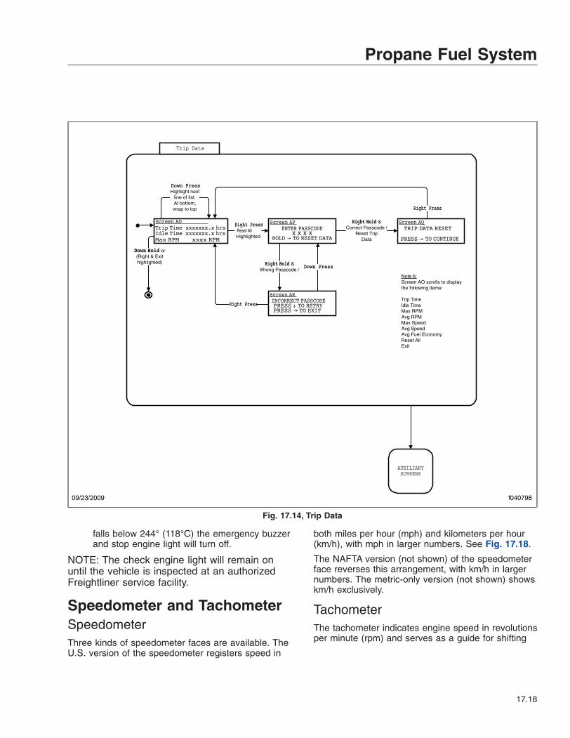
falls below 244° (118°C) the emergency buzzerand stop engine light will turn off.
NOTE: The check engine light will remain onuntil the vehicle is inspected at an authorizedFreightliner service facility.
Speedometer and TachometerSpeedometerThree kinds of speedometer faces are available. TheU.S. version of the speedometer registers speed in
both miles per hour (mph) and kilometers per hour(km/h), with mph in larger numbers. See Fig. 17.18.
The NAFTA version (not shown) of the speedometerface reverses this arrangement, with km/h in largernumbers. The metric-only version (not shown) showskm/h exclusively.
TachometerThe tachometer indicates engine speed in revolutionsper minute (rpm) and serves as a guide for shifting
Trip Data
AUXILIARYSCREENS
Note 6:Screen AO scrolls to display the following items:
Trip TimeIdle TimeMax RPMAvg RPMMax SpeedAvg SpeedAvg Fuel EconomyReset AllExit
Right PressReset AllHighlighted
Correct Passcode /Reset Trip
Data
Right Press
Down PressHighlight next
line of list.At bottom,wrap to top
(Right & Exithighlighted)
Wrong Passcode /Down Press
Right Press
09/23/2009 f040798
Fig. 17.14, Trip Data
Propane Fuel System
17.18

the transmission and keeping the engine in the ap-propriate rpm range. See Fig. 17.18.
Standard InstrumentsFuel Level GaugeThe fuel level gauge indicates the level of fuel in thefuel tanks. See Fig. 17.19. A low-level warning lightilluminates when the diesel fuel level registers 1/8thof capacity.
Engine Oil Pressure Gauge
NOTICEA sudden decrease or absence of oil pressuremay indicate mechanical failure. Bring the vehicleto a safe stop and investigate the cause to pre-vent further damage. Do not operate the engineuntil the cause has been determined and cor-rected.
If the engine oil pressure falls below preset levels,the check engine light will illuminate. If the conditiondoes not improve, the CHECK engine light and lowoil pressure warning light will also illuminate and thebuzzer will sound. See Fig. 17.20. At this point, theengine will derate or shut down, depending on thetype of engine protection system installed.
Coolant Temperature Gauge
NOTICEA sudden increase in coolant temperature mayindicate engine or cooling system failure. Bringthe vehicle to a safe stop and investigate thecause to prevent further damage. Do not operatethe engine until the cause has been determinedand corrected.
During normal engine operation, the coolant tem-perature gauge should read 200 to 205°F (93 to96°C). See Fig. 17.21. If the temperature remainsbelow 160°F (71°C) or exceeds 235°F (113°C), in-spect the cooling system to determine the cause.
02/06/2012 f040799
WARNING MESSAGES
DISPLAY MESSAGES
H*
WARNING Warning Message
No WarningMessages in List /
Msg Displayed for 5 Sec. /Display Next Entry in
Warning Message List
Any Button Press
/Display 1st Message
in WarningMessage List
Screen AN
Fig. 17.15, Warning Messages
Propane Fuel System
17.19
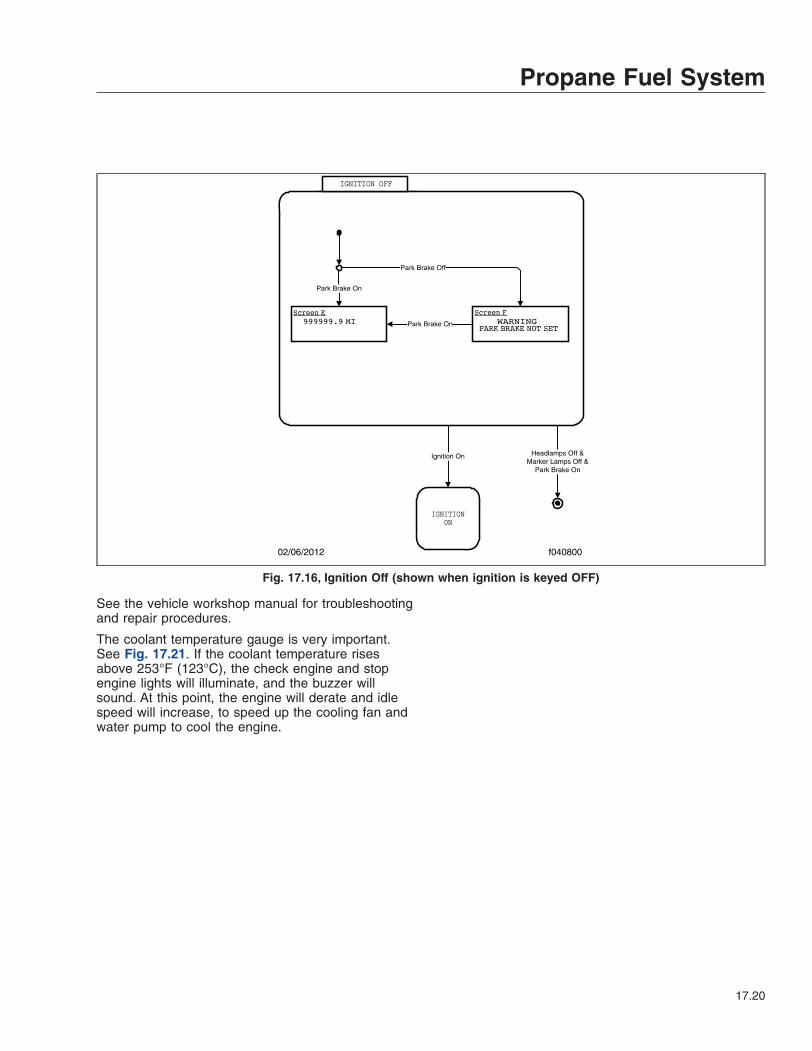
See the vehicle workshop manual for troubleshootingand repair procedures.
The coolant temperature gauge is very important.See Fig. 17.21. If the coolant temperature risesabove 253°F (123°C), the check engine and stopengine lights will illuminate, and the buzzer willsound. At this point, the engine will derate and idlespeed will increase, to speed up the cooling fan andwater pump to cool the engine.
IGNITION OFF
Park Brake On
Park Brake On
Park Brake Off
IGNITIONON
Headlamps Off &Marker Lamps Off &
Park Brake On
Ignition On
02/06/2012 f040800
Fig. 17.16, Ignition Off (shown when ignition is keyed OFF)
Propane Fuel System
17.20

07/22/2014 f611241
1
2
3 4 5 6 7 8 9 10 11 12 13 14
15
16
1718
19
20 21
22
1. Maintenance Warning Light2. Left-Turn Signal Arrow3. High Exhaust System
Temperature (HEST) Lamp (notused)
4. Check Engine Indicator5. Stop Engine Warning6. Malfunction Indicator Lamp (MIL)7. Engine Brake Light (not used)
8. Low Air Pressure Warning9. Wait to Start Indicator10. ABS Indicator11. Shift Inhibit Indicator12. Check Transmission Indicator13. Stop Transmission Indicator14. Diesel Particulate Filter (DPF)
Lamp (not used)15. Right-Turn Signal Arrow
16. Fasten Seat Belts Warning17. Hydraulic Brake System Warning18. Headlight High-Beam Indicator19. Traction Control Indicator (not
used)20. Parking Brake On Indicator21. Cruise Control Indicator22. Auxiliary Power Generator (not
used)
Fig. 17.17, LPG Engine Warning and Indicator Lights
07/22/2014 f611239
1 2
1. Tachometer (optional) 2. Speedometer
Fig. 17.18, Speedometer and Tachometer (U.S. version)
Propane Fuel System
17.21

07/21/2014 f611236
1
1. Low Fuel Level Warning Light
Fig. 17.19, Fuel Level Gauge (typical gauge shown)
07/21/2014 f611237
1
1. Low Oil Pressure Warning Light
Fig. 17.20, Engine Oil Pressure Gauge
07/21/2014 f611238
1
1. High Coolant Temperature Warning Light
Fig. 17.21, Coolant Temperature Gauge
Propane Fuel System
17.22

18
SpecificationsTorque Charts . . . . . . . . . . . . . . . . . . . . . . . . . . . . . . . . . . . . . . . . . . . . . . . . . . . . . . . . . . . . . . . . . . . 18.1Conversion Charts . . . . . . . . . . . . . . . . . . . . . . . . . . . . . . . . . . . . . . . . . . . . . . . . . . . . . . . . . . . . . . . 18.4Fluid and Lubricant Specifications . . . . . . . . . . . . . . . . . . . . . . . . . . . . . . . . . . . . . . . . . . . . . . . . . . . 18.5Fuse/Relay/Circuit Breaker Identification . . . . . . . . . . . . . . . . . . . . . . . . . . . . . . . . . . . . . . . . . . . . . 18.5

Torque ChartsTorque Values for U.S. Customary Thread Fasteners With Lubricated* or Plated Threads†
ThreadDiameter—
Pitch
Regular Hex FlangedGrade 5
BoltGrade 5 or
B NutGrade 8 or
8.2 BoltGrade 8 or
C NutGrade 5
BoltGrade B
NutGrade 8 or
8.2 BoltGrade G
NutTorque: lbf·ft (N·m) Torque: lbf·ft (N·m) Torque: lbf·ft (N·m) Torque: lbf·ft (N·m)
f230002 f230003 f230004 f230005 f230006 f230007 f230008 f230009
1/4–20 7 (9) 8 (11) 6 (8) 10 (14)1/4–28 8 (11) 9 (12) 7 (9) 12 (16)
5/16–18 15 (20) 16 (22) 13 (18) 21 (28)5/16–24 16 (22) 17 (23) 14 (19) 23 (31)3/8–16 26 (35) 28 (38) 23 (31) 37 (50)3/8–24 30 (41) 32 (43) 25 (34) 42 (57)
7/16–14 42 (57) 45 (61) 35 (47) 60 (81)7/16–20 47 (64) 50 (68) 40 (54) 66 (89)1/2–13 64 (87) 68 (92) 55 (75) 91 (123)1/2–20 72 (98) 77 (104) 65 (88) 102 (138)
9/16–12 92 (125) 98 (133) 80 (108) 130 (176)9/16–18 103 (140) 110 (149) 90 (122) 146 (198)
5/8–11 128 (173) 136 (184) 110 (149) 180 (244)5/8–18 145 (197) 154 (209) 130 (176) 204 (277)3/4–10 226 (306) 241 (327) 200 (271) 320 (434)3/4–16 253 (343) 269 (365) 220 (298) 357 (484)7/8–9 365 (495) 388 (526) 320 (434) 515 (698)
7/8–14 402 (545) 427 (579) 350 (475) 568 (770)1–8 — 582 (789) — —
1–12 — 637 (863) — —1–14 — 652 (884) — —
* FCCC recommends that all plated and unplated fasteners be coated with oil before installation.† Use these torque values if either the bolt or nut is lubricated or plated (zinc-phosphate conversion-coated, cadmium-plated, or waxed, Geomet 321XL
coated, or waxed).
Table 18.1, Torque Values for U.S. Customary Thread Fasteners With Lubricated or Plated Threads
Specifications
18.1
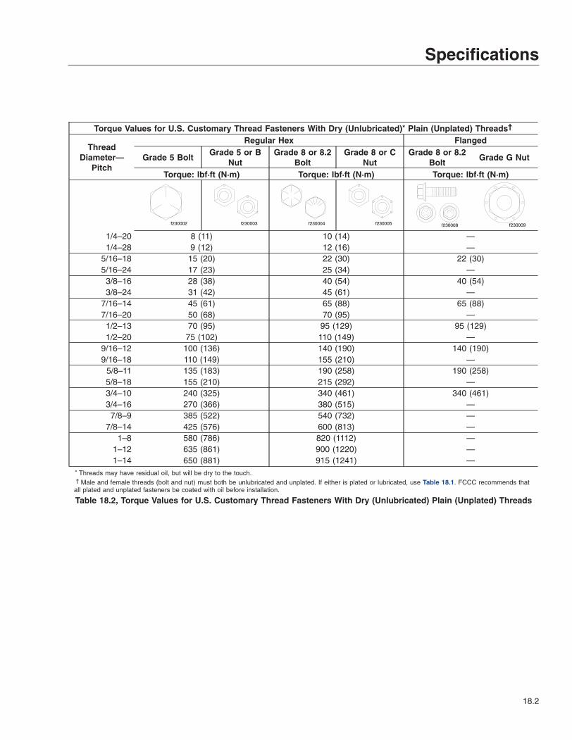
Torque Values for U.S. Customary Thread Fasteners With Dry (Unlubricated)* Plain (Unplated) Threads†
ThreadDiameter—
Pitch
Regular Hex Flanged
Grade 5 BoltGrade 5 or B
NutGrade 8 or 8.2
BoltGrade 8 or C
NutGrade 8 or 8.2
BoltGrade G Nut
Torque: lbf·ft (N·m) Torque: lbf·ft (N·m) Torque: lbf·ft (N·m)
f230002 f230003 f230004 f230005 f230008 f230009
1/4–20 8 (11) 10 (14) —1/4–28 9 (12) 12 (16) —
5/16–18 15 (20) 22 (30) 22 (30)5/16–24 17 (23) 25 (34) —3/8–16 28 (38) 40 (54) 40 (54)3/8–24 31 (42) 45 (61) —
7/16–14 45 (61) 65 (88) 65 (88)7/16–20 50 (68) 70 (95) —1/2–13 70 (95) 95 (129) 95 (129)1/2–20 75 (102) 110 (149) —
9/16–12 100 (136) 140 (190) 140 (190)9/16–18 110 (149) 155 (210) —
5/8–11 135 (183) 190 (258) 190 (258)5/8–18 155 (210) 215 (292) —3/4–10 240 (325) 340 (461) 340 (461)3/4–16 270 (366) 380 (515) —7/8–9 385 (522) 540 (732) —
7/8–14 425 (576) 600 (813) —1–8 580 (786) 820 (1112) —
1–12 635 (861) 900 (1220) —1–14 650 (881) 915 (1241) —
* Threads may have residual oil, but will be dry to the touch.† Male and female threads (bolt and nut) must both be unlubricated and unplated. If either is plated or lubricated, use Table 18.1. FCCC recommends that
all plated and unplated fasteners be coated with oil before installation.
Table 18.2, Torque Values for U.S. Customary Thread Fasteners With Dry (Unlubricated) Plain (Unplated) Threads
Specifications
18.2

Torque Values for Metric Thread Fasteners With Lubricated* or Plated Threads†
ThreadDiameter—
Pitch
Class 8.8 Bolt Class 8 Nut Class 10.9 Bolt Class 10 Nut
Torque: lbf·ft (N·m) Torque: lbf·ft (N·m)
f230010
8.8
f230011
8
f230012
10.9
f230013
10
M6 5 (7) 7 (9)M8 12 (16) 17 (23)M8 x 1 13 (18) 18 (24)M10 24 (33) 34 (46)M10 x 1.25 27 (37) 38 (52)M12 42 (57) 60 (81)M12 x 1.5 43 (58) 62 (84)M14 66 (89) 95 (129)M14 x 1.5 72 (98) 103 (140)M16 103 (140) 148 (201)M16 x 1.5 110 (149) 157 (213)M18 147 (199) 203 (275)M18 x 1.5 165 (224) 229 (310)M20 208 (282) 288 (390)M20 x 1.5 213 (313) 320 (434)M22 283 (384) 392 (531)M22 x 1.5 315 (427) 431 (584)M24 360 (488) 498 (675)M24 x 2 392 (531) 542 (735)M27 527 (715) 729 (988)M27 x 2 569 (771) 788 (1068)M30 715 (969) 990 (1342)M30 x 2 792 (1074) 1096 (1486)* FCCC recommends that all plated and unplated fasteners be coated with oil before installation.† Use these torque values if either the bolt or nut is lubricated or plated (zinc-phosphate conversion-coated,
cadmium-plated, or waxed, Geomet 321XL coated, or waxed).
Table 18.3, Torque Values for Metric Thread Fasteners With Lubricated or PlatedThreads
Specifications
18.3

Conversion ChartsWhen You Know U.S.
CustomaryMultiply
ByTo Get Metric
When YouKnow Metric
MultiplyBy
To Get U.S. Customary
Lengthinches (in) 25.4 millimeters (mm) 0.03937 inches (in)inches (in) 2.54 centimeters (cm) 0.3937 inches (in)feet (ft) 0.3048 meters (m) 3.281 feet (ft)yards (yd) 0.9144 meters (m) 1.094 yards (yd)miles (mi) 1.609 kilometers (km) 0.6215 miles (mi)Areasquare inches (in2) 645.16 square millimeters (mm2) 0.00155 square inches (in2)square inches (in2) 6.452 square centimeters (cm2) 0.155 square inches (in2)square feet (ft2) 0.0929 square meters (m2) 10.764 square feet (ft2)Volumecubic inches (in3) 16387.0 cubic millimeter (mm3) 0.000061 cubic inches (in3)cubic inches (in3) 16.387 cubic centimeters (cm3) 0.06102 cubic inches (in3)cubic inches (in3) 0.01639 liters (L) 61.024 cubic inches (in3)fluid ounces (fl oz) 29.54 milliliters (mL) 0.03381 fluid ounces (fl oz)pints (pt) 0.47318 liters (L) 2.1134 pints (pt)quarts (qt) 0.94635 liters (L) 1.0567 quarts (qt)gallons (gal) 3.7854 liters (L) 0.2642 gallons (gal)cubic feet (ft3) 28.317 liters (L) 0.03531 cubic feet (ft3)cubic feet (ft3) 0.02832 cubic meters (m3) 35.315 cubic feet (ft3)Weight/Forceounces (av) (oz) 28.35 grams (g) 0.03527 ounces (av) (oz)pounds (av) (lb) 0.454 kilograms (kg) 2.205 pounds (av) (lb)U.S. tons (t) 907.18 kilograms (kg) 0.001102 U.S. tons (t)U.S. tons (t) 0.90718 metric tons (t) 1.1023 U.S. tons (t)Torque/Work Forceinch–pounds (lbf·in) 11.298 Newton–centimeters (N·cm) 0.08851 inch–pounds (lbf·in)foot–pounds (lbf·ft) 1.3558 Newton–meters (N·m) 0.7376 foot–pounds (lbf·ft)Pressure/Vacuuminches of mercury (inHg) 3.37685 kilo Pascals (kPa) 0.29613 inches of mercury (inHg)pounds per square inch (psi) 6.895 kilo Pascals (kPa) 0.14503 pounds per square inch (psi)
Table 18.4, Metric/U.S. Customary Conversion
When You Know SubtractThen
Divide ByTo Get
When YouKnow
MultiplyBy
ThenAdd
To Get
degrees Fahrenheit (°F) 32 1.8 degrees Celsius (°C) 1.8 32 degrees Fahrenheit (°F)
Table 18.5, Temperature Conversion
Specifications
18.4

Fluid and LubricantSpecificationsSee Table 18.6 for fluid and lubricant specifications.
Fluid and Lubricant SpecificationsComponent Recommended Fluid or Lubricant
Front Axle Spindle Pins, Tie Rods, Drag Link,Intermediate Steering Shaft, Front Brake andPedal Shafts, Slip Spline and Universal Joints
Multipurpose Grease Lithium 12 Hydroxy Stearate NLGI No. 2; fortemperatures below 0°F (–18°C), use MIL-G-10924B
Hydraulic Brake Master Cylinder Heavy-Duty DOT 3 Brake FluidBrake and Pedal Pivots Starplex 2 (lithium soap-based grease)Engine See Manufacturer’s RecommendationsTransmission See Manufacturer’s Recommendations
Fuel
Ultralow-Sulfur Diesel Fuel
CMS 20067 (CNG Engines)
HD5 Grade PropaneDisc Brake Caliper Rails FCCC No. 4JD623 Brake Caliper Slide GreaseRear Axle Differential See Manufacturer’s RecommendationsHydraulic System Reservoir Dexron® III ATF or equivalent
Engine Coolant
50% Water/50% Ethylene Glycol Antifreeze (diesel engines)
50% Water/50% DEX-COOL® Coolant (gasoline and propane enginesonly)
Table 18.6, Fluid and Lubricant Specifications
Fuse/Relay/Circuit BreakerIdentificationNOTE: The fuse/circuit breaker panel is locatedunder the instrument panel to the left of thesteering column. Circuit breakers protect againstcircuit overload. If a circuit becomes overloaded(usually caused by a short to ground), the circuitbreaker opens, stopping current flow. Auto-resetbreakers are installed. Depending on vehicleoptions, fuse/circuit breaker locations may varyfrom those shown. A power distribution panelmay also be installed on the vehicle. This panelhouses plug-in fuses and relays. See Fig. 18.1and Fig. 18.2.
Specifications
18.5
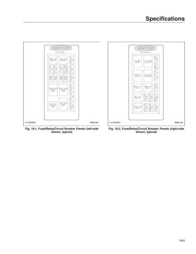
11/16/2007 f080149
Fig. 18.1, Fuse/Relay/Circuit Breaker Panels (left-sideshown, typical)
11/16/2007 f080148
Fig. 18.2, Fuse/Relay/Circuit Breaker Panels (right-sideshown, typical)
Specifications
18.6

Subject Page
AAir Brake System . . . . . . . . . . . . . . . . . . . . . . . . . 7.2
Air Brake System WithExternal Fill (Shrader)Valve . . . . . . . . . . . . . . . . . . . . . . . . . . . . . . 7.2
Automatic Slack Adjusters . . . . . . . . . . . . . . . . . 7.3General Information . . . . . . . . . . . . . . . . . . . . . 7.2Operation . . . . . . . . . . . . . . . . . . . . . . . . . . . . 7.3
Allison Automatic Transmissions . . . . . . . . . . . . . . . 5.1Driving Precautions . . . . . . . . . . . . . . . . . . . . . 5.1General Information . . . . . . . . . . . . . . . . . . . . . 5.1Operating Instructions, On-
Highway Transmissions . . . . . . . . . . . . . . . . . 5.2Range Inhibit Indicator, 2000
Series . . . . . . . . . . . . . . . . . . . . . . . . . . . . . 5.2Series 1000, 2000, and 2500
Transmission Operation . . . . . . . . . . . . . . . . . 5.1Ametek Instrument Panel . . . . . . . . . . . . . . . . . . . 2.1
Menu Navigation . . . . . . . . . . . . . . . . . . . . . . . 2.9Menu System . . . . . . . . . . . . . . . . . . . . . . . . . 2.1Message Display Center . . . . . . . . . . . . . . . . . . 2.1Priority Messages . . . . . . . . . . . . . . . . . . . . . . 2.1Self-Test . . . . . . . . . . . . . . . . . . . . . . . . . . . . 2.1
BBraking and Steering Controls . . . . . . . . . . . . . . . . 3.5
Parking Brake Control . . . . . . . . . . . . . . . . . . . 3.5Tilt/Telescope Steering
Column . . . . . . . . . . . . . . . . . . . . . . . . . . . . 3.6
CCare of Chrome Parts . . . . . . . . . . . . . . . . . . . . . 12.1Changing a Flat Tire . . . . . . . . . . . . . . . . . . . . . . 13.3CNG Fuel Tank Filling
Procedure . . . . . . . . . . . . . . . . . . . . . . . . . . . . 8.1CNG General Information . . . . . . . . . . . . . . . . . . . 8.1CNG Safety Precautions . . . . . . . . . . . . . . . . . . . . 8.3
CNG General SafetyInformation . . . . . . . . . . . . . . . . . . . . . . . . . . 8.3
CNG Workshop Precautions . . . . . . . . . . . . . . . 8.4Major Repair and
Replacement of CNG Parts . . . . . . . . . . . . . . . 8.4Servicing the CNG System . . . . . . . . . . . . . . . . 8.4
Component Information Label . . . . . . . . . . . . . . . . 1.1Conversion Charts . . . . . . . . . . . . . . . . . . . . . . . 18.4
DDaily Pretrip Inspection and
Maintenance Checklist . . . . . . . . . . . . . . . . . . . 10.2
Subject PageDaily Pretrip Inspection and
Maintenance Procedures . . . . . . . . . . . . . . . . . . 11.1Dashboard and Instrument
Panel Care . . . . . . . . . . . . . . . . . . . . . . . . . . . 12.1Dash-Mounted Controls . . . . . . . . . . . . . . . . . . . . 3.6
Aftertreatment System (ATS)Regen Switch . . . . . . . . . . . . . . . . . . . . . . . . 3.6
Low Idle Adjustment Switch . . . . . . . . . . . . . . . . 3.7Windshield Washer Switch . . . . . . . . . . . . . . . . 3.7Windshield Wiper Switch . . . . . . . . . . . . . . . . . . 3.7
Disabling the Hybrid ElectricVehicle (HEV) System . . . . . . . . . . . . . . . . . . . . 9.4Option 1 (preferred method) . . . . . . . . . . . . . . . . 9.4Option 2 . . . . . . . . . . . . . . . . . . . . . . . . . . . . . 9.4Option 3 . . . . . . . . . . . . . . . . . . . . . . . . . . . . . 9.4
Driving the Vehicle . . . . . . . . . . . . . . . . . . . . . . 16.17Fuel Economy . . . . . . . . . . . . . . . . . . . . . . . 16.17
EElectrical System General
Information . . . . . . . . . . . . . . . . . . . . . . . . . . . . 3.1Battery Disconnect Switch
(optional) . . . . . . . . . . . . . . . . . . . . . . . . . . . 3.1Emergency Procedures . . . . . . . . . . . . . . . . . . . 16.20
Fluid Spill . . . . . . . . . . . . . . . . . . . . . . . . . . 16.20Manual Bleed-Down . . . . . . . . . . . . . . . . . . . 16.20
Emergency Starting WithJumper Cables . . . . . . . . . . . . . . . . . . . . . . . . 13.1
Emissions Labels . . . . . . . . . . . . . . . . . . . . . . . . . 1.1Aftertreatment System
Indicators Label . . . . . . . . . . . . . . . . . . . . . . 1.1Certified Clean Idle Label . . . . . . . . . . . . . . . . . 1.3Vehicle Emission Control
Information Label . . . . . . . . . . . . . . . . . . . . . 1.2Engine Break-In . . . . . . . . . . . . . . . . . . . . . . . . . 15.3Engine Coolant . . . . . . . . . . . . . . . . . . . . . . . . . 15.4Engine Oil . . . . . . . . . . . . . . . . . . . . . . . . . . . . 15.5
Changing the Engine Oil . . . . . . . . . . . . . . . . . 15.5Checking the Engine Oil . . . . . . . . . . . . . . . . . 15.5Engine Oil Additives . . . . . . . . . . . . . . . . . . . . 15.5Engine Oil Flushing . . . . . . . . . . . . . . . . . . . . 15.5
Engine Operation . . . . . . . . . . . . . . . . . . . . . . . . . 4.2Cold-Weather Operation . . . . . . . . . . . . . . . . . . 4.2Engine Shutdown . . . . . . . . . . . . . . . . . . . . . . 17.3Engine Starting . . . . . . . . . . . . . . . . . . . . . . . 17.2General Information . . . . . . . . . . . . . . . . . . . . 17.2Normal Operation . . . . . . . . . . . . . . . . . . . . . . 4.2
Engine Shutdown . . . . . . . . . . . . . . . . . . . . . . . . 4.9Engine Starting and Shutdown . . . . . . . . . . . . . . . . 9.1
Engine Shutdown . . . . . . . . . . . . . . . . . . . . . . 9.2Engine Starting . . . . . . . . . . . . . . . . . . . . . . . . 9.1Idle-Off Shutdown Procedure . . . . . . . . . . . . . . . 9.2
Index
I-1

Subject PageEngine Starting . . . . . . . . . . . . . . . . . . . . . . . . . . 8.2
Cold-Weather Starting . . . . . . . . . . . . . . . . . . . 4.2General Information . . . . . . . . . . . . . . . . . . . . . 4.1Normal Starting . . . . . . . . . . . . . . . . . . . . . . . . 4.1
Exhaust Aftertreatment System(ATS) . . . . . . . . . . . . . . . . . . . . . . . . . . . . . . . 4.3DEF Gauge . . . . . . . . . . . . . . . . . . . . . . . . . . 4.7DEF Tank . . . . . . . . . . . . . . . . . . . . . . . . . . . . 4.7DEF Warnings and Engine
Limits . . . . . . . . . . . . . . . . . . . . . . . . . . . . . 4.7Diesel Exhaust Fluid and
Tank, EPA10 and NewerEngines . . . . . . . . . . . . . . . . . . . . . . . . . . . . 4.6
EPA07 Engines . . . . . . . . . . . . . . . . . . . . . . . . 4.4EPA10 and Newer Engines . . . . . . . . . . . . . . . . 4.4
FFast Idle System . . . . . . . . . . . . . . . . . . . . . . . . 15.3
Fast Idle Operation . . . . . . . . . . . . . . . . . . . . . 15.3Fluid and Lubricant
Specifications . . . . . . . . . . . . . . . . . . . . . . . . . 18.5Foot Pedal-Operated Parking
Brake . . . . . . . . . . . . . . . . . . . . . . . . . . . . . . . 9.1Front Towing Hookup . . . . . . . . . . . . . . . . . . . . . 14.1
Front Towing Hookup . . . . . . . . . . . . . . . . . . . 14.1Fuel . . . . . . . . . . . . . . . . . . . . . . . . . . . . . . . . . 15.4
Additives . . . . . . . . . . . . . . . . . . . . . . . . . . . 15.4Gasoline Octane . . . . . . . . . . . . . . . . . . . . . . 15.4Gasoline Specifications . . . . . . . . . . . . . . . . . . 15.4
Fuse/Relay/Circuit BreakerIdentification . . . . . . . . . . . . . . . . . . . . . . . . . . 18.5
GGeneral Information . . . . . . . . . . . . . . . . . . . . . . 17.1
HHazard Warning Lights . . . . . . . . . . . . . . . . . . . . 13.1High Idle Options . . . . . . . . . . . . . . . . . . . . . . . . . 4.3
High Idle with Cruise Control . . . . . . . . . . . . . . . 4.3Voltage-Based Auto High
Idle . . . . . . . . . . . . . . . . . . . . . . . . . . . . . . . 4.3Horn Controls . . . . . . . . . . . . . . . . . . . . . . . . . . . 3.3Hydraulic Brake System . . . . . . . . . . . . . . . . . . . . 7.1
General Information . . . . . . . . . . . . . . . . . . . . . 7.1Meritor WABCO® Antilock
Braking System (ABS) . . . . . . . . . . . . . . . . . . 7.1Operation . . . . . . . . . . . . . . . . . . . . . . . . . . . . 7.1
Hydraulic Gauges, WarningIndicators, and MessageDisplays . . . . . . . . . . . . . . . . . . . . . . . . . . . . . 16.6Gauges . . . . . . . . . . . . . . . . . . . . . . . . . . . . 16.6
Subject Page
Menu System . . . . . . . . . . . . . . . . . . . . . . . 16.10Message Displays . . . . . . . . . . . . . . . . . . . . . 16.9Warning and Indicator Lights . . . . . . . . . . . . . . 16.6
Hydraulic Hybrid Drive System . . . . . . . . . . . . . . . 16.2Functional Differences . . . . . . . . . . . . . . . . . . . 16.2System Components . . . . . . . . . . . . . . . . . . . 16.3
IIgnition Switch and Key . . . . . . . . . . . . . . . . . . . . 3.1In Case of an Emergency . . . . . . . . . . . . . . . . . . . 9.5
High-Voltage SafetyFeatures . . . . . . . . . . . . . . . . . . . . . . . . . . . 9.5
JJumpstarting and Towing . . . . . . . . . . . . . . . . . . 16.20
Emergency Starting WithJumper Cables . . . . . . . . . . . . . . . . . . . . . 16.20
Towing Hookup . . . . . . . . . . . . . . . . . . . . . . 16.20
LLighting Controls . . . . . . . . . . . . . . . . . . . . . . . . . 3.1
Hazard Warning Light Tab . . . . . . . . . . . . . . . . . 3.2Headlight and Panel Light
Controls . . . . . . . . . . . . . . . . . . . . . . . . . . . . 3.2Headlight High-Beam/
Dimmer Switch . . . . . . . . . . . . . . . . . . . . . . . 3.2
MMonthly Post-Trip Inspection
and Maintenance Checklist . . . . . . . . . . . . . . . . 10.3Monthly Post-Trip Inspection
and Maintenance Procedures . . . . . . . . . . . . . . 11.11
OOptional Instruments . . . . . . . . . . . . . . . . . . . . . . 2.19
Air Intake Restriction Gauge . . . . . . . . . . . . . . 2.19Single Air Pressure Gauge
for Hydraulic Brakes withAir Provision . . . . . . . . . . . . . . . . . . . . . . . . 2.20
Tachometer . . . . . . . . . . . . . . . . . . . . . . . . . . 2.20Transmission Fluid
Temperature Gauge . . . . . . . . . . . . . . . . . . . 2.20
PPower Steering System . . . . . . . . . . . . . . . . . . . . 6.1Powertrain Controls . . . . . . . . . . . . . . . . . . . . . . . 3.3
Allison AutomaticTransmissions . . . . . . . . . . . . . . . . . . . . . . . . 3.3
Index
I-2

Subject Page
Backup Alarm (optional) . . . . . . . . . . . . . . . . . . 3.5Cruise Control (optional) . . . . . . . . . . . . . . . . . . 3.4Manual Dump Valve
(optional) . . . . . . . . . . . . . . . . . . . . . . . . . . . 3.5Pretrip and Post-Trip Inspection
General Information . . . . . . . . . . . . . . . . . . . . . 10.1Pretrip Inspection . . . . . . . . . . . . . . . . . . . . . . . 16.12
Daily Pretrip Inspection andMaintenance Procedures . . . . . . . . . . . . . . . 16.13
Daily Pretrip Inspections/Checks . . . . . . . . . . . . . . . . . . . . . . . . . . 16.12
Propane Refueling . . . . . . . . . . . . . . . . . . . . . . . 17.3
RRear Towing Hookup . . . . . . . . . . . . . . . . . . . . . 14.1Running Out of Fuel . . . . . . . . . . . . . . . . . . . . . . 13.3
Compressed Natural Gas(CNG) Engines . . . . . . . . . . . . . . . . . . . . . . 13.4
Diesel Engines . . . . . . . . . . . . . . . . . . . . . . . 13.3
SSafety Features . . . . . . . . . . . . . . . . . . . . . . . . 16.18
Brake Energy RecoveryBypass . . . . . . . . . . . . . . . . . . . . . . . . . . . 16.18
High Pressure SafetyDevices . . . . . . . . . . . . . . . . . . . . . . . . . . 16.18
Low Pressure SafetyDevices . . . . . . . . . . . . . . . . . . . . . . . . . . 16.19
Manual Bleed-Down Valve . . . . . . . . . . . . . . . 16.18Safety Precautions . . . . . . . . . . . . . . . . . . . . . . . . 9.1Speedometer and Tachometer . . . . . . . . . . . . . . . 2.16
Speedometer . . . . . . . . . . . . . . . . . . . . . . . . 15.18Tachometer . . . . . . . . . . . . . . . . . . . . . . . . . 15.18
Standard Instruments . . . . . . . . . . . . . . . . . . . . . 2.17Coolant Temperature Gauge . . . . . . . . . . . . . . 2.18Engine Oil Pressure Gauge . . . . . . . . . . . . . . . 2.17Fuel Level Gauge . . . . . . . . . . . . . . . . . . . . . 2.17High Coolant Temperature
Warning . . . . . . . . . . . . . . . . . . . . . . . . . . . 2.18Low Fuel Warning Light . . . . . . . . . . . . . . . . . . 2.17Low Oil Pressure Warning . . . . . . . . . . . . . . . . 2.18Primary and Secondary Air
Pressure Gauges . . . . . . . . . . . . . . . . . . . . . 2.18Starting the Engine . . . . . . . . . . . . . . . . . . . . . . . 15.1
General Information . . . . . . . . . . . . . . . . . . . . 15.1MIL Lamp . . . . . . . . . . . . . . . . . . . . . . . . . . . 15.2
Steering General Information . . . . . . . . . . . . . . . . . 6.1
TT-Handle Shifter . . . . . . . . . . . . . . . . . . . . . . . . . 9.3
Subject Page
1 (Low Gear) . . . . . . . . . . . . . . . . . . . . . . . . . 9.4D (Drive) . . . . . . . . . . . . . . . . . . . . . . . . . . . . 9.3H (Hold) . . . . . . . . . . . . . . . . . . . . . . . . . . . . . 9.4N (Neutral) . . . . . . . . . . . . . . . . . . . . . . . . . . . 9.3P (Park) . . . . . . . . . . . . . . . . . . . . . . . . . . . . . 9.3R (Reverse) . . . . . . . . . . . . . . . . . . . . . . . . . . 9.3
Tilt/Telescope Steering Column . . . . . . . . . . . . . . . 6.1Foot Pedal Adjustment
(optional) . . . . . . . . . . . . . . . . . . . . . . . . . . . 6.2Lever Adjustment (optional) . . . . . . . . . . . . . . . . 6.1
Torque Charts . . . . . . . . . . . . . . . . . . . . . . . . . . 18.1Towing . . . . . . . . . . . . . . . . . . . . . . . . . . . . . . . 13.1Transmission Shift Pad . . . . . . . . . . . . . . . . . . . 16.12
Gear Selection . . . . . . . . . . . . . . . . . . . . . . . 16.12Turn Signal Switch . . . . . . . . . . . . . . . . . . . . . . . . 3.3
VVehicle Identification Number
(VIN) . . . . . . . . . . . . . . . . . . . . . . . . . . . . . . . . 1.1
WWarning and Indicator Lights . . . . . . . . . . . . . . . . . 2.9
ABS Indicator . . . . . . . . . . . . . . . . . . . . . . . . 2.13Air Brake Indicator . . . . . . . . . . . . . . . . . . . . . 2.15Auxiliary Power Generator
(hybrid only) . . . . . . . . . . . . . . . . . . . . . . . . 2.16Brake System Warning/
Parking Brake On Indicator . . . . . . . . . . . . . 15.16Check Engine Indicator . . . . . . . . . . . . . . . . . . 2.12Check Transmission
Indicator . . . . . . . . . . . . . . . . . . . . . . . . . . . 2.13Cruise Control Indicator . . . . . . . . . . . . . . . . . . 2.16Diesel Particulate Filter
(DPF) Lamp . . . . . . . . . . . . . . . . . . . . . . . . 2.14Emergency Buzzer . . . . . . . . . . . . . . . . . . . . 15.17Engine Brake Light . . . . . . . . . . . . . . . . . . . . . 2.12Fasten Seat Belt Warning . . . . . . . . . . . . . . . . 2.15Fasten Seat Belts Warning . . . . . . . . . . . . . . . 15.15General Information . . . . . . . . . . . . . . . . . . . . . 2.9Headlight High-Beam
Indicator . . . . . . . . . . . . . . . . . . . . . . . . . . . 2.15High Exhaust System
Temperature (HEST) Lamp . . . . . . . . . . . . . . 2.11Hydraulic Brake System
Warning . . . . . . . . . . . . . . . . . . . . . . . . . . . 2.15Left-Turn Signal Arrow . . . . . . . . . . . . . . . . . . . 2.11Low Air Pressure Warning . . . . . . . . . . . . . . . 15.14Maintenance Warning Light . . . . . . . . . . . . . . . 2.10Malfunction Indicator Lamp
(MIL) . . . . . . . . . . . . . . . . . . . . . . . . . . . . 15.14Malfunction Indicator Lamp . . . . . . . . . . . . . . . 2.12
Index
I-3

Subject Page
Parking Brake On Indicator . . . . . . . . . . . . . . . 2.15Right-Turn Signal Arrow . . . . . . . . . . . . . . . . . 2.15Shift Inhibit Indicator . . . . . . . . . . . . . . . . . . . . 2.13Stop Engine Warning . . . . . . . . . . . . . . . . . . . 2.12Stop Transmission (hybrid
only) . . . . . . . . . . . . . . . . . . . . . . . . . . . . . 2.14Stop Transmission Indicator . . . . . . . . . . . . . . 15.15Wait to Start Indicator . . . . . . . . . . . . . . . . . . 15.14Wait to Start Warning Light . . . . . . . . . . . . . . . 2.12
Washing and Polishing . . . . . . . . . . . . . . . . . . . . 12.1Weekly Post-Trip Inspection
and Maintenance Checklist . . . . . . . . . . . . . . . . 10.3Weekly Post-Trip Inspection
and Maintenance Procedures . . . . . . . . . . . . . . . 11.9
Index
I-4