
W5100 Datasheet v1 1 6
70
© Copyright 2008 WIZnet Co., Inc. All rights reserved. 1 W5100 Datasheet W5100 Datasheet Version 1.1.6 © 2008 WIZnet Co., Inc. All Rights Reserved. For more information, visit our website at http://www.wiznet.co.kr
Transcript of W5100 Datasheet v1 1 6

© Copyright 2008 WIZnet Co., Inc. All rights reserved. 1
W5100 D
atasheet
W5100 Datasheet Version 1.1.6
© 2008 WIZnet Co., Inc. All Rights Reserved.
For more information, visit our website at http://www.wiznet.co.kr

© Copyright 2008 WIZnet Co., Inc. All rights reserved. 2
W5100 D
atasheet
Document History Information
Version Date Descriptions
Ver. 1.0.0 Dec. 21, 2006 Released with W5100 Launching
Ver. 1.0.1 Jan. 10, 2006 LB bit in Mode register is not used .
W5100 is used only in Big-endian ordering.
Ver. 1.1.1 Jun. 19, 2007 Modified the OPMODE2-0 signals descriptions (P. 10) Modified the TEST_MODE3-0 signals description (P.11) Modified the Colck signals description (P.12) Modified the LINKLED signal description (P.12) Modified the explanation of RECV_INT in Sn_IR register (P. 27) Replaced the reset value of Sn_DHAR register (0x00 to 0xFF, P. 30) Modifted the explanation of Sn_DIPR, Sn_DPORT register(P. 31) Replaced the reset value of Sn_MSS register (0xFFFF to 0x0000, P. 31)
Ver. 1.1.2 Sep. 28, 2007 Modified the Operating temperature (P. 63)
Ver. 1.1.3 Oct. 18, 2007 Changed the wrong word “MISO signal” (P. 10) Modified the SPI Timing diagram and description (P. 66)
Ver. 1.1.4 Oct. 18, 2007 Modified the diagram (P. 40)
Ver. 1.1.5 Nov. 11, 2007 Modified the Crystal Characteristics value (P. 67)
Ver. 1.1.6 Jan. 30, 2008 Modified the SEN signals description (P.10) Changed the wrong word “SCLK” (P. 66)

© Copyright 2008 WIZnet Co., Inc. All rights reserved. 3
W5100 D
atasheet
WIZnet’s online Technical Support
If you have something to ask about WIZnet Products, write down your
question on Q&A Board of ‘Support’ menu in WIZnet website
(www.wiznet.co.kr). WIZnet Engineer will give an answer as soon as
possible.
CClliicckk
© Copyright 2008 WIZnet Co., Inc. All rights reserved. 4
W5100 D
atasheet
W5100 Datasheet
The W5100 is a full-featured, single-chip Internet-enabled 10/100 Ethernet controller
designed for embedded applications where ease of integration, stability, performance, area
and system cost control are required. The W5100 has been designed to facilitate easy
implementation of Internet connectivity without OS. The W5100 is IEEE 802.3 10BASE-T and
802.3u 100BASE-TX compliant.
The W5100 includes fully hardwired, market-proven TCP/IP stack and integrated Ethernet
MAC & PHY. Hardwired TCP/IP stack supports TCP, UDP, IPv4, ICMP, ARP, IGMP and PPPoE
which has been proven in various applications for several years. 16Kbytes internal buffer is
included for data transmission. No need of consideration for handling Ethernet Controller, but
simple socket programming is required.
For easy integration, three different interfaces like memory access way, called direct,
indirect bus and SPI, are supported on the MCU side.
Target Applications The W5100 is well suited for many embedded applications, including:
- Home Network Devices: Set-Top Boxes, PVRs, Digital Media Adapters
- Serial-to-Ethernet: Access Controls, LED displays, Wireless AP relays, etc.
- Parallel-to-Ethernet: POS / Mini Printers, Copiers
- USB-to-Ethernet: Storage Devices, Network Printers
- GPIO-to-Ethernet: Home Network Sensors
- Security Systems: DVRs, Network Cameras, Kiosks
- Factory and Building Automations
- Medical Monitoring Equipments
- Embedded Servers

© Copyright 2008 WIZnet Co., Inc. All rights reserved. 5
W5100 D
atasheet
Features - Support Hardwired TCP/IP Protocols : TCP, UDP, ICMP, IPv4 ARP, IGMP, PPPoE, Ethernet
- 10BaseT/100BaseTX Ethernet PHY embedded
- Support Auto Negotiation (Full-duplex and half duplex)
- Support Auto MDI/MDIX
- Support ADSL connection (with support PPPoE Protocol with PAP/CHAP Authentication
mode)
- Supports 4 independent sockets simultaneously
- Not support IP Fragmentation
- Internal 16Kbytes Memory for Tx/Rx Buffers
- 0.18 µm CMOS technology
- 3.3V operation with 5V I/O signal tolerance
- Small 80 Pin LQFP Package
- Lead-Free Package
- Support Serial Peripheral Interface(SPI MODE 0, 3)
- Multi-function LED outputs (TX, RX, Full/Half duplex, Collision, Link, Speed)

© Copyright 2008 WIZnet Co., Inc. All rights reserved. 6
W5100 D
atasheet
Block Diagram
© Copyright 2008 WIZnet Co., Inc. All rights reserved. 7
W5100 D
atasheet
Table of Contents
1. Pin Assignment ...................................................................................................................8
1.1 MCU Interface Signals ................................................................................................9
1.2 PHY Signals..............................................................................................................10
1.3 Miscellaneous Signals...............................................................................................11
1.4 Power Supply Signals ...............................................................................................11
1.5 Clock Signals ...........................................................................................................12
1.6 LED Signals ..............................................................................................................12
2. Memory Map ....................................................................................................................13
3. W5100 Registers ...............................................................................................................14
3.1 common registers ....................................................................................................14
3.2 Socket registers.......................................................................................................15
4. Register Descriptions........................................................................................................19
4.1 Common Registers ...................................................................................................19
4.2 Socket Registers ......................................................................................................25
5. Functional Descriptions ....................................................................................................37
5.1 Initialization............................................................................................................37
5.2.1 TCP ...............................................................................................................40
5.2.1.1 SERVER mode.......................................................................................41
5.2.1.2 CLIENT mode .......................................................................................48
5.2.2 UDP ...............................................................................................................50
5.2.3 IP raw............................................................................................................56
5.2.4 MAC raw ........................................................................................................57
6. Application Information....................................................................................................59
6.1 Direct Bus Interface mode .......................................................................................59
6.2 Indirect Bus Interface mode ....................................................................................59
6.3 SPI (Serial Peripheral Interface) mode .....................................................................60
6.3.1 Device Operations .........................................................................................61
6.3.2 Commands.....................................................................................................61
6.3.3 Process of using general SPI Master device (According to SPI protocol).........61
7. Electrical Specifications ...................................................................................................63
8. IR Reflow Temperature Profile (Lead-Free) .......................................................................68
9. Package Descriptions........................................................................................................69

© Copyright 2008 WIZnet Co., Inc. All rights reserved. 8
W5100 D
atasheet
1. Pin Assignment
Pinout W5100

© Copyright 2008 WIZnet Co., Inc. All rights reserved. 9
W5100 D
atasheet
1.1 MCU Interface Signals
Symbol Type Pin No Description
/RESET I 59 RESET
This pin is active Low input to initialize or re-
initialize W5100.
By asserting this pin low for at least 2us, all internal
registers will be re-initialized to their default states.
ADDR14-0 I 38, 39,
40, 41,
42, 45,
46, 47,
48, 49,
50, 51,
52, 53,
54
ADDRESS
These pins are used to select a register or memory.
Address pins are internally pulled down.
DATA7-0 I/O 19, 20,
21, 22,
23, 24,
25, 26
DATA
These pins are used to read and write register or
memory data.
/CS I 55 CHIP SELECT
Chip Select is for MCU to access to internal registers
or memory. /WR and /RD select direction of data
transfer. This pin is active low.
/INT O 56 INTERRUPT
This pin Indicates that W5100 requires MCU
attention after socket connecting, disconnecting,
data receiving or timeout. The interrupt is cleared
by writing IR(Interrupt Register) or Sn_IR (Socket nth
Interrupt Register). All interrupts are maskable. This
pin is active low.
/WR I 57 WRITE ENABLE
Strobe from MCU to write an internal
register/memory selected by ADDR[14:0]. Data is
latched into the W5100 on the rising edge of this
input. This signal is active low.
/RD I 58 READ ENABLE

© Copyright 2008 WIZnet Co., Inc. All rights reserved. 10
W5100 D
atasheet
Strobe from MCU to read an internal
register/memory selected by ADDR[14:0]. This signal
is active low.
SEN I 31 SPI ENABLE
This pin selects Enable/disable of the SPI Mode.
Low = SPI Mode Disable
High = SPI Mode Enable
If you don’t use SPI mode, then you tied this signal
to ‘0’.
SCLK I 30 SPI CLOCK
This pin is used to SPI Clock signal Pin.
/SCS I 29 SPI SLAVE SELECT
This pin is used to SPI Slave Select signal Pin. This
pin is active low
MOSI I 28 SPI MASTER OUT SLAVE IN
This pin is used to SPI MOSI signal pin.
MISO O 27 SPI MASTER IN SLAVE OUT
This pin is used to SPI MISO signal pin.
1.2 PHY Signals
Symbol Type Pin No Description
RXIP
I 5
RXIN
I 6
RXIP/RXIN Signal Pair
The differential data from the media is received on
the RXIP/RXIN signal pair.
TXOP O 8
TXON O 9
TXOP/TXON Signal Pair
The differential data is transmitted to the media on
the TXOP/TXIN signal pair.
RSET_BG O 1 PHY Off-chip resistor
Connect a resistor of 12.3 ㏀±1% to the ground.
Refer to the “Reference schematic”.
OPMODE2-0 I 65, 64,
63
OPERATION CONTROL MODE
[2:0] Description
000 Auto-negotiation enable with all capabilities

© Copyright 2008 WIZnet Co., Inc. All rights reserved. 11
W5100 D
atasheet
001 Auto-negotiation with 100 BASE-TX FDX/HDX ability
010 Auto-negotiation with 10 BASE-T FDX/HDX ability
011 Reserved
100 Manual selection of 100 BASE-TX FDX
101 Manual selection of 100 BASE-TX HDX
110 Manual selection of 10 BASE-T FDX
111 Manual selection of 10 BASE-T HDX
1.3 Miscellaneous Signals
Symbol Type Pin No Description
TEST_MODE3-0 I 34, 35,
36, 37
W5100 MODE SELECT
Normal mode : 0000
Other test modes are internal test mode.
NC I/O 3, 60,
61, 62,
78, 79,
80
NC
TEST PIN for W5100
( for factory use only)
1.4 Power Supply Signals
Symbol Type Pin No Description
VCC3V3A Power 2 3.3V power supply for Analog part
VCC3V3D Power 12, 18, 44 3.3V power supply for Digital part
VCC1V8A Power 7, 74 1.8V power supply for Analog part
VCC1V8D Power 15, 16,
33, 69
1.8V power supply for Digital part
GNDA Ground 4, 10, 77 Analog ground
GNDD Ground 13, 14, 17,
32, 43, 68,
Digital ground

© Copyright 2008 WIZnet Co., Inc. All rights reserved. 12
W5100 D
atasheet
V18 O 11 1.8V regulator output voltage
1.5 Clock Signals
Symbol Type Pin No Description
XTLP I 76
XTLN 75
25MHz crystal input/output
A 25MHz parallel-resonant crystal is used to connect
these pins to stabilize the internal oscillator
If you want to use oscillator, 25MHz clock to connect
XTLP signals and XTLN is open.
MUST use 1.8V level oscillator.
1.6 LED Signals
Symbol Type Pin No Description
LINKLED O 66 Link LED
Active low in link state indicates a good status for
10/100M.
It is always ON when the link is OK and it flashes
while in a TX or RX state.
SPDLED O 67 Link speed LED
Active low indicates the link speed is 100Mbps.
FDXLED O 70 Full duplex LED
Active low indicates the status of full-duplex mode.
COLLED O 71 Collision LED
Active low indicates the presence of collision
activity.
RXLED O 72 Receive activity LED
Active low indicates the presence of receiving
activity.
TXLED O 73 Transmit activity LED
Active low indicates the presence of transmitting
activity.

© Copyright 2008 WIZnet Co., Inc. All rights reserved. 13
W5100 D
atasheet
2. Memory Map W5100 is composed of Common Register, Socket Register, TX Memory, and RX Memory as
shown below.
0x0000 Common Registers
0x0030 Reserved
0x0400
Socket Registers
0x0800
Reserved
0x4000
TX memory
0x6000
RX memory
0x8000
Memory Map

© Copyright 2008 WIZnet Co., Inc. All rights reserved. 14
W5100 D
atasheet
3. W5100 Registers 3.1 common registers
Address Register
0x0000 Mode (MR)
0x0001
0x0002
0x0003
0x0004
Gateway Address
(GAR0)
(GAR1)
(GAR2)
(GAR3)
0x0005
0x0006
0x0007
0x0008
Subnet mask Address
(SUBR0)
(SUBR1)
(SUBR2)
(SUBR3)
0x0009
0x000A
0x000B
0x000C
0x000D
0x000E
Source Hardware Address
(SHAR0)
(SHAR1)
(SHAR2)
(SHAR3)
(SHAR4)
(SHAR5)
0x000F
0x0010
0x0011
0x0012
Source IP Address
(SIPR0)
(SIPR1)
(SIPR2)
(SIPR3)
0x0013
0x0014
Reserved
0x0015 Interrupt (IR)
0x0016 Interrupt Mask (IMR)
0x0017
0x0018
Retry Time
(RTR0)
(RTR1)
0x0019 Retry Count (RCR)
Address Register
0x001A RX Memory Size (RMSR)
0x001B TX Memory Size (TMSR)
0x001C
0x001D
Authentication Type in PPPoE
(PATR0)
(PATR1)
0x001E
~
0x0027
Reserved
0x0028 PPP LCP Request Timer
(PTIMER)
0x0029 PPP LCP Magic number
(PMAGIC)
0x002A
0x002B
0x002C
0x002D
Unreachable IP Address
(UIPR0)
(UIPR1)
(UIPR2)
(UIPR3)
0x002E
0x002F
Unreachable Port
(UPORT0)
(UPORT1)
0x0030
~
0x03FF
Reserved

© Copyright 2008 WIZnet Co., Inc. All rights reserved. 15
W5100 D
atasheet
3.2 Socket registers
Address Register
0x0400 Socket 0 Mode (S0_MR)
0x0401 Socket 0 Command (S0_CR)
0x0402 Socket 0 Interrupt (S0_IR)
0x0403 Socket 0 Status (S0_SR)
0x0404
0x0405
Socket 0 Source Port
(S0_PORT0)
(S0_PORT1)
0x0406
0x0407
0x0408
0x0409
0x040A
0x040B
Socket 0 Destination Hardware Address
(S0_DHAR0)
(S0_DHAR1)
(S0_DHAR2)
(S0_DHAR3)
(S0_DHAR4)
(S0_DHAR5)
0x040C
0x040D
0x040E
0x040F
Socket 0 Destination IP Address
(S0_DIPR0)
(S0_DIPR1)
(S0_DIPR2)
(S0_DIPR3)
0x0410
0x0411
Socket 0 Destination Port
(S0_DPORT0)
(S0_DPORT1)
0x0412
0x0413
Socket 0 Maximum Segment Size
(S0_MSSR0)
(S0_MSSR1)
0x0414
Socket 0 Protocol in IP Raw mode
(S0_PROTO)
Address Register
0x0415 Socket 0 IP TOS (S0_TOS)
0x0416 Socket 0 IP TTL (S0_TTL)
0x0417
~
0x041F
Reserved
0x0420
0x0421
Socket 0 TX Free Size
(S0_TX_FSR0)
(S0_TX_FSR1)
0x0422
0x0423
Socket 0 TX Read Pointer
(S0_TX_RD0)
(S0_TX_RD1)
0x0424
0x0425
Socket 0 TX Write Pointer
(S0_TX_WR0)
(S0_TX_WR1)
0x0426
0x0427
Socket 0 RX Received Size
(S0_RX_RSR0)
(S0_RX_RSR1)
0x0428
0x0429
Socket 0 RX Read Pointer
(S0_RX_RD0)
(S0_RX_RD1)
0x042A
0x042B
Reserved
0x042C
~
0x04FF
Reserved

© Copyright 2008 WIZnet Co., Inc. All rights reserved. 16
W5100 D
atasheet
Address Register
0x0500 Socket 1 Mode (S1_MR)
0x0501 Socket 1 Command (S1_CR)
0x0502 Socket 1 Interrupt (S1_IR)
0x0503 Socket 1 Status (S1_SR)
0x0504
0x0505
Socket 1 Source Port
(S1_PORT0)
(S1_PORT1)
0x0506
0x0507
0x0508
0x0509
0x050A
0x050B
Socket 1 Destination Hardware Address
(S1_DHAR0)
(S1_DHAR1)
(S1_DHAR2)
(S1_DHAR3)
(S1_DHAR4)
(S1_DHAR5)
0x050C
0x050D
0x050E
0x050F
Socket 1 Destination IP Address
(S1_DIPR0)
(S1_DIPR1)
(S1_DIPR2)
(S1_DIPR3)
0x0510
0x0511
Socket 1 Destination Port
(S1_DPORT0)
(S1_DPORT1)
0x0512
0x0513
Socket 1 Maximum Segment Size
(S1_MSSR0)
(S1_MSSR1)
0x0514
Socket 1 Protocol in IP Raw mode
(S1_PROTO)
Address Register
0x0515 Socket 1 IP TOS (S1_TOS)
0x0516 Socket 1 IP TTL (S1_TTL)
0x0517
~
0x051F
Reserved
0x0520
0x0521
Socket 1 TX Free Size
(S1_TX_FSR0)
(S1_TX_FSR1)
0x0522
0x0523
Socket 1 TX Read Pointer
(S1_TX_RD0)
(S1_TX_RD1)
0x0524
0x0525
Socket 1 TX Write Pointer
(S1_TX_WR0)
(S1_TX_WR1)
0x0526
0x0527
Socket 1 RX Received Size
(S1_RX_RSR0)
(S1_RX_RSR1)
0x0528
0x0529
Socket 1 RX Read Pointer
(S1_RX_RD0)
(S1_RX_RD1)
0x052A
0x052B
Reserved
0x052C
~
0x05FF
Reserved
© Copyright 2008 WIZnet Co., Inc. All rights reserved. 17
W5100 D
atasheet
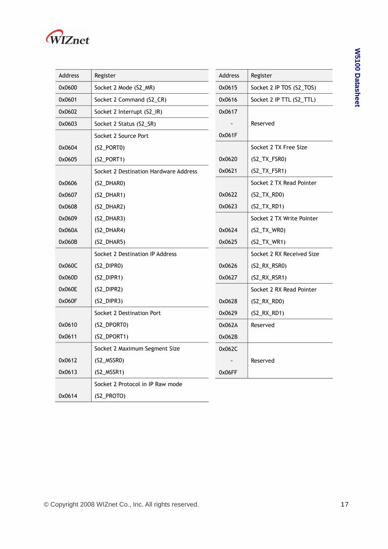
Address Register
0x0600 Socket 2 Mode (S2_MR)
0x0601 Socket 2 Command (S2_CR)
0x0602 Socket 2 Interrupt (S2_IR)
0x0603 Socket 2 Status (S2_SR)
0x0604
0x0605
Socket 2 Source Port
(S2_PORT0)
(S2_PORT1)
0x0606
0x0607
0x0608
0x0609
0x060A
0x060B
Socket 2 Destination Hardware Address
(S2_DHAR0)
(S2_DHAR1)
(S2_DHAR2)
(S2_DHAR3)
(S2_DHAR4)
(S2_DHAR5)
0x060C
0x060D
0x060E
0x060F
Socket 2 Destination IP Address
(S2_DIPR0)
(S2_DIPR1)
(S2_DIPR2)
(S2_DIPR3)
0x0610
0x0611
Socket 2 Destination Port
(S2_DPORT0)
(S2_DPORT1)
0x0612
0x0613
Socket 2 Maximum Segment Size
(S2_MSSR0)
(S2_MSSR1)
0x0614
Socket 2 Protocol in IP Raw mode
(S2_PROTO)
Address Register
0x0615 Socket 2 IP TOS (S2_TOS)
0x0616 Socket 2 IP TTL (S2_TTL)
0x0617
~
0x061F
Reserved
0x0620
0x0621
Socket 2 TX Free Size
(S2_TX_FSR0)
(S2_TX_FSR1)
0x0622
0x0623
Socket 2 TX Read Pointer
(S2_TX_RD0)
(S2_TX_RD1)
0x0624
0x0625
Socket 2 TX Write Pointer
(S2_TX_WR0)
(S2_TX_WR1)
0x0626
0x0627
Socket 2 RX Received Size
(S2_RX_RSR0)
(S2_RX_RSR1)
0x0628
0x0629
Socket 2 RX Read Pointer
(S2_RX_RD0)
(S2_RX_RD1)
0x062A
0x062B
Reserved
0x062C
~
0x06FF
Reserved

© Copyright 2008 WIZnet Co., Inc. All rights reserved. 18
W5100 D
atasheet
Address Register
0x0700 Socket 3 Mode (S3_MR)
0x0701 Socket 3 Command (S3_CR)
0x0702 Socket 3 Interrupt (S3_IR)
0x0703 Socket 3 Status (S3_SR)
0x0704
0x0705
Socket 3 Source Port
(S3_PORT0)
(S3_PORT1)
0x0706
0x0707
0x0708
0x0709
0x070A
0x070B
Socket 3 Destination Hardware Address
(S3_DHAR0)
(S3_DHAR1)
(S3_DHAR2)
(S3_DHAR3)
(S3_DHAR4)
(S3_DHAR5)
0x070C
0x070D
0x070E
0x070F
Socket 3 Destination IP Address
(S3_DIPR0)
(S3_DIPR1)
(S3_DIPR2)
(S3_DIPR3)
0x0710
0x0711
Socket 3 Destination Port
(S3_DPORT0)
(S3_DPORT1)
0x0712
0x0713
Socket 3 Maximum Segment Size
(S3_MSSR0)
(S3_MSSR1)
0x0714
Socket 3 Protocol in IP Raw mode
(S3_PROTO)
Address Register
0x0715 Socket 3 IP TOS (S3_TOS)
0x0716 Socket 3 IP TTL (S3_TTL)
0x0717
~
0x071F
Reserved
0x0720
0x0721
Socket 3 TX Free Size
(S3_TX_FSR0)
(S3_TX_FSR1)
0x0722
0x0723
Socket 3 TX Read Pointer
(S3_TX_RD0)
(S3_TX_RD1)
0x0724
0x0725
Socket 3 TX Write Pointer
(S3_TX_WR0)
(S3_TX_WR1)
0x0726
0x0727
Socket 3 RX Received Size
(S3_RX_RSR0)
(S3_RX_RSR1)
0x0728
0x0729
Socket 3 RX Read Pointer
(S3_RX_RD0)
(S3_RX_RD1)
0x072A
0x072B
Reserved
0x072C
~
0x07FF
Reserved

© Copyright 2008 WIZnet Co., Inc. All rights reserved. 19
W5100 D
atasheet
4. Register Descriptions
4.1 Common Registers
MR (Mode Register) [R/W] [0x0000] [0x00]
This register is used for S/W reset, memory test mode, ping block mode, PPPoE mode and
Indirect bus I/F.
7 6 5 4 3 2 1 0
RST PB PPPoE AI IND
Bit Symbol Description
7 RST
S/W Reset
If this bit is ‘1’, internal register will be initialized. It will be automatically
cleared after reset.
6 Reserved Reserved
5 Reserved Reserved
4 PB
Ping Block Mode
0 : Disable Ping block
1 : Enable Ping block
If the bit is set as ‘1’, there is no response to the ping request.
3 PPPoE
PPPoE Mode
0 : Disable PPPoE mode
1 : Enable PPPoE mode
If you use ADSL without router or etc, you should set the bit as ‘1’ to
connect to ADSL Server. For more detail, refer to the application note,
“How to connect ADSL”.
2 Not Used Not Used
1 AI
Address Auto-Increment in Indirect Bus I/F
0 : Disable auto-increment
1 : Enable auto-increment
At the Indirect Bus I/F mode, if this bit is set as ‘1’, the address will be
automatically increased by 1 whenever read and write are performed. For
more detail, refer to “6.2 Indirect Bus IF Mode”.
0 IND Indirect Bus I/F mode

© Copyright 2008 WIZnet Co., Inc. All rights reserved. 20
W5100 D
atasheet
0 : Disable Indirect bus I/F mode
1 : Enable Indirect bus I/F mode
If this bit is set as ‘1’, Indirect BUS I/F mode is set. For more detail, refer
to “6. Application Information”, “6.2 Indirect Bus IF Mode”.
GWR (Gateway IP Address Register) [R/W] [0x0001 – 0x0004] [0x00]
This Register sets up the default gateway address.
Ex) in case of “192.168.0.1”
0x0001 0x0002 0x0003 0x0004
192 (0xC0) 168 (0xA8) 0 (0x00) 1 (0x01)
SUBR (Subnet Mask Register) [R/W] [0x0005 – 0x0008] [0x00]
This register sets up the subnet mask address.
Ex) in case of “255.255.255.0”
0x0005 0x0006 0x0007 0x0008
255 (0xFF) 255 (0xFF) 255 (0xFF) 0 (0x00)
SHAR (Source Hardware Address Register) [R/W] [0x0009 – 0x000E] [0x00]
This register sets up the Source Hardware address.
Ex) In case of “00.08.DC.01.02.03”
0x0009 0x000A 0x000B 0x000C 0x000D 0x000E
0x00 0x08 0xDC 0x01 0x02 0x03
SIPR (Source IP Address Register) [R/W] [0x000F – 0x0012] [0x00]
This register sets up the Source IP address.
Ex) in case of “192.168.0.3”
0x000F 0x0010 0x0011 0x0012
192 (0xC0) 168 (0xA8) 0 (0x00) 3 (0x03)

© Copyright 2008 WIZnet Co., Inc. All rights reserved. 21
W5100 D
atasheet
IR (Interrupt Register) [R] [0x0015] [0x00]
This register is accessed by the host processor to know the cause of an interrupt.
Any interrupt can be masked in the Interrupt Mask Register (IMR). The /INT signal retain low
as long as any masked signal is set, and will not go high until all masked bits in this Register
have been cleared.
7 6 5 4 3 2 1 0
CONFLICT UNREACH PPPoE Reserved S3_INT S2_INT S1_INT S0_INT
Bit Symbol Description
7 CONFLICT
IP Conflict
It is set as ‘1’, when there is ARP request with same IP address as Source IP
address. This bit is cleared to ‘0’ by writing ‘1’ to this bit.
6 UNREACH
Destination unreachable
W5100 will receive ICMP(Destination Unreachable) packet if non-existing
destination IP address is transmitted during UDP data transmission. (Refer
to “5.2.2 UDP”). In this case, the IP address and the port number will be
saved in Unreachable IP Address (UIPR) and Unreachable Port Register
(UPORT), and the bit will be set as ‘1’. This bit will be cleared to ‘0’ by
writing ‘1’ to this bit.
5 PPPoE
PPPoE Connection Close
In the PPPoE Mode, if the PPPoE connection is closed, ‘1’ is set. This bit
will be cleared to ‘0’ by writing ‘1’ to this bit.
4 Reserved Reserved
3 S3_INT
Occurrence of Socket 3 Socket Interrupt
It is set in case that interrupt occurs at the socket 3. For more detailed
information of socket interrupt, refer to “Socket 3 Interrupt Register
(S3_IR)”. This bit will be automatically cleared when S3_IR is cleared to
0x00.
2 S2_INT
Occurrence of Socket 2 Socket Interrupt
It is set in case that interrupt occurs at the socket 2. For more detailed
information of socket interrupt, refer to “Socket 2 Interrupt
Register(S2_IR)”. This bit will be automatically cleared when S2_IR is
cleared to 0x00.
1 S1_INT
Occurrence of Socket 1 Socket Interrupt
It is set in case that interrupt occurs at the socket 1. For more detailed
information of socket interrupt, refer to “Socket 1 Interrupt Register

© Copyright 2008 WIZnet Co., Inc. All rights reserved. 22
W5100 D
atasheet
(S1_IR)”. This bit will be automatically cleared when S1_IR is cleared to
0x00.
0 S0_INT
Occurrence of Socket 0 Socket Interrupt
It is set in case that interrupt occurs at the socket 0. For more detailed
information of socket interrupt, refer to “Socket 0 Interrupt Register
(S0_IR)”. This bit will be automatically cleared when S0_IR is cleared to
0x00.
IMR (Interrupt Mask Register) [R/W] [0x0016] [0x00]
The Interrupt Mask Register is used to mask interrupts. Each interrupt mask bit corresponds to
a bit in the Interrupt Register (IR). If an interrupt mask bit is set, an interrupt will be issued
whenever the corresponding bit in the IR is set. If any bit in the IMR is set as ‘0’, an interrupt
will not occur though the bit in the IR is set.
7 6 5 4 3 2 1 0
IM_IR7 IM_IR6 IM_IR5 Reserved IM_IR3 IM_IR2 IM_IR1 IM_IR0
Bit Symbol Description
7 IM_IR7 IP Conflict Enable
6 IM_IR6 Destination unreachable Enable
5 IM_IR5 PPPoE Close Enable
4 Reserved It should be set as ‘0’
3 IM_IR3 Occurrence of Socket 3 Socket Interrupt Enable
2 IM_IR2 Occurrence of Socket 2 Socket Interrupt Enable
1 IM_IR1 Occurrence of Socket 1 Socket Interrupt Enable
0 IM_IR0 Occurrence of Socket 0 Socket Interrupt Enable
RTR (Retry Time-value Register) [R/W] [0x0017 – 0x0018] [0x07D0]
This register sets the period of timeout. Value 1 means 100us. The initial value is
2000(0x07D0). That will be set as 200ms.
Ex) For 400ms configuration, set as 4000(0x0FA0)
0x0017 0x0018
0x0F 0xA0
Re-transmission will occur if there is no response from the remote peer to the commands of
CONNECT, DISCON, CLOSE, SEND, SEND_MAC and SEND_KEEP, or the response is delayed.

© Copyright 2008 WIZnet Co., Inc. All rights reserved. 23
W5100 D
atasheet
RCR (Retry Count Register) [R/W] [0x0019] [0x08]
This register sets the number of re-transmission. If retransmission occurs more than the
number recorded in RCR, Timeout Interrupt (TIMEOUT bit of Socket n Interrupt Register
(Sn_IR) is set as ‘1’) will occur.
RMSR(RX Memory Size Register) [R/W] [0x001A] [0x55]
This register assigns total 8K RX Memory to each socket.
7 6 5 4 3 2 1 0
Socket 3 Socket 2 Socket 1 Socket 0
S1 S0 S1 S0 S1 S0 S1 S0
The memory size according to the configuration of S1, S0, is as below.
S1 S0 Memory size
0 0 1KB
0 1 2KB
1 0 4KB
1 1 8KB
According to the value of S1 and S0, the memory is assigned to the sockets from socket 0
within the range of 8KB. If there is not enough memory to be assigned, the socket should not
be used. The initial value is 0x55 and the 2K memory is assigned to each 4 sockets
respectively.
Ex) When setting as 0xAA, the 4KB memory should be assigned to each socket.
However, the total memory size is 8KB. The memory is normally assigned to the socket 0 and
1, but not to the socket 2 and 3. Therefore, socket 2 and 3 can not be absolutely used.
Socket 3 Socket 2 Socket 1 Socket 0
0KB 0KB 4KB 4KB
TMSR(TX Memory Size Register) [R/W] [0x001B] [0x55]
This register is used in assigning total 8K TX Memory to sockets. Configuration can be done in
the same way of RX Memory Size Register (RMSR). The initial value is 0x55 and it is to assign
2K memory to 4 sockets respectively.

© Copyright 2008 WIZnet Co., Inc. All rights reserved. 24
W5100 D
atasheet
PATR (Authentication Type in PPPoE mode) [R] [0x001C-0x001D] [0x0000]
This register notifies authentication method that has been agreed at the connection with
PPPoE Server. W5100 supports two types of Authentication method - PAP and CHAP.
Value Authentication Type
0xC023 PAP
0xC223 CHAP
PTIMER (PPP Link Control Protocol Request Timer Register) [R/W] [0x0028] [0x28]
This register indicates the duration for sending LCP Echo Request. Value 1 is about 25ms.
Ex) in case that PTIMER is 200,
200 * 25(ms) = 5000(ms) = 5 seconds
PMAGIC (PPP Link Control Protocol Magic number Register) [R/W] [0x0029] [0x00]
This register is used in Magic number option during LCP negotiation. Refer to the application
note, “How to connect ADSL”.
UIPR (Unreachable IP Address Register) [R] [0x002A – 0x002D] [0x00]
In case of data transmission using UDP (refer to “5.2.2. UDP”), if transmitting to non-existing
IP address, ICMP (Destination Unreachable) packet will be received. In this case, that IP
address and port number will be saved in the Unreachable IP Address Register(UIPR) and
Unreachable Port Register(UPORT) respectively.
Ex) in case of “192.168.0.11”,
0x002A 0x002B 0x002C 0x002D
192 (0xC0) 168 (0xA8) 0 (0x00) 11 (0x0B)
UPORT (Unreachable Port Register) [R] [0x002E – 0x002F] [0x0000]
Refer to Unreachable IP Address Register (UIPR)
Ex) In case of 5000(0x1388),
0x002E 0x002F
0x13 0x88
© Copyright 2008 WIZnet Co., Inc. All rights reserved. 25
W5100 D
atasheet
4.2 Socket Registers
Sn1_MR (Socket n Mode Register) [R/W] [0x0400, 0x0500, 0x0600, 0x0700] [0x00]2
This register sets up socket option or protocol type for each socket.
7 6 5 4 3 2 1 0
MULTI ND / MC P3 P2 P1 P0
Bit Symbol Description
7 MULTI
Multicasting
0 : disable Multicasting
1 : enable Multicasting
It is applied only in case of UDP.
For using multicasting, write multicast group address to Socket n Destination
IP and multicast group port number to Socket n Destination Port Register,
before OPEN command.
6 Reserved Reserved
5 ND/MC
Use No Delayed ACK
0 : Disable No Delayed ACK option
1 : Enable No Delayed ACK option,
It is applied only in case of TCP. If this bit is set as ‘1’, ACK packet is
transmitted whenever receiving data packet from the peer. If this bit is
cleared to ‘0’, ACK packet is transmitted according to internal Timeout
mechanism.
Multicast
0 : using IGMP version 2
1 : using IGMP version 1
It is applied only in case of MULTI bit is ‘1’
4 Reserved Reserved
3 P3
2 P2
Protocol
Sets up corresponding socket as TCP, UDP, or IP RAW mode
P3 P2 P1 P0 Meaning
0 0 0 0 Closed
0 0 0 1 TCP
1 n is socket number (0, 1, 2, 3). 2 [Read/Write] [address of socket 0, address of socket 1, address of socket 2, address of socket 3] [Reset value]

© Copyright 2008 WIZnet Co., Inc. All rights reserved. 26
W5100 D
atasheet
1 P1
0 P0
0 0 1 0 UDP
0 0 1 1 IPRAW
* In case of socket 0, MACRAW and PPPoE mode exist.
P3 P2 P1 P0 Meaning
0 1 0 0 MACRAW
0 1 0 1 PPPoE
Sn_CR (Socket n Command Register) [R/W] [0x0401, 0x0501, 0x0601, 0x0701] [0x00]
This register is utilized for socket n initialization, close, connection establishment,
termination, data transmission and command receipt. After performing the commands, the
register value will be automatically cleared to 0x00.
Value Symbol Description
0x01 OPEN
It is used to initialize the socket. According to the value of Socket n
Mode Register (Sn_MR), Socket n Status Register(Sn_SR) value is
changed to SOCK_INIT, SOCK_UDP, SOCK_IPRAW, or SOCK_MACRAW.
For more detail, refer to 5. Functional Description.
0x02 LISTEN
It is only used in TCP mode.
It changes the value of Socket n Status Register (Sn_SR) to SOCK_LISTEN
in order to wait for a connection request from any remote peer (TCP
Client).
For more detail, refer to 5.2.1.1 SERVER mode.
0x04 CONNECT
It is only used in TCP mode.
It sends a connection request to remote peer(TCP SERVER). If the
connection is failed, Timeout interrupt will occur.
For more detail, refer to 5.2.1.2 CLIENT mode.
0x08 DISCON
It is only used in TCP mode.
It sends a connection termination request. If connection termination is
failed, Timeout interrupt will occur. For more detail, refer to 5.2.1.1
SERVER mode.
* In case of using CLOSE command instead of DISCON, only the value of
Socket n Status Register(Sn_SR) is changed to SOCK_CLOSED without
the connection termination process.
0x10 CLOSE It is used to close the socket. It changes the value of Socket n Status
Register(Sn_SR) to SOCK_CLOSED.

© Copyright 2008 WIZnet Co., Inc. All rights reserved. 27
W5100 D
atasheet
0x20 SEND
It transmits the data as much as the increased size of Socket n TX Write
Pointer. For more detail, refer to Socket n TX Free Size Register
(Sn_TX_FSR), Socket n TX Write Pointer Register(Sn_TX_WR), and Socket
n TX Read Pointer Register(Sn_TX_RR) or 5.2.1.1. SERVER mode.
0x21 SEND_MAC
It is used in UDP mode.
The basic operation is same as SEND. Normally SEND operation needs
Destination Hardware Address that is received in ARP(Address Resolution
Protocol) process. SEND_MAC uses Socket n Destination Hardware
Address(Sn_DHAR) that is written by users without ARP process.
0x22 SEND_KEEP
It is only used in TCP mode.
It checks the connection status by sending 1byte data. If the connection
is already terminated or peer has no response, Timeout interrupt will
occur.
0x40 RECV
Receiving is processed with the value of Socket n RX Read Pointer
Register(Sn_RX_RD).
For more detail, refer to 5.2.1.1 SERVER mode Receiving Process with
Socket n RX Received Size Register (Sn_RX_RSR), Socket n RX Write
Pointer Register(Sn_RX_WR), and Socket n RX Read Pointer
Register(Sn_RX_RD)
Sn_IR (Socket n Interrupt Register) [R] [0x0402, 0x0502, 0x0602, 0x0702] [0x00]
This register is used for notifying connection establishment and termination, receiving data
and Timeout. The Socket n Interrupt Register must be cleared by writing ‘1’.
7 6 5 4 3 2 1 0
Reserved Reserved Reserved SEND_OK TIMEOUT RECV DISCON CON
Bit Symbol Description
7 Reserved Reserved
6 Reserved Reserved
5 Reserved Reserved
4 SEND_OK It is set as ‘1’ if send operation is completed.
3 TIMEOUT It is set as ‘1’ if Timeout occurs during connection establishment or
termination and data transmission.
2 RECV It is set as ‘1’ whenever W5100 receives data. And it is also set as ‘1’

© Copyright 2008 WIZnet Co., Inc. All rights reserved. 28
W5100 D
atasheet
if received data remains after execute CMD_RECV command.
1 DISCON It is set as ‘1’ if connection termination is requested or finished.
0 CON It is set as ‘1’ if connection is established.
Sn_SR (Socket n Status Register) [R] [0x0403, 0x0503, 0x0603, 0x0703] [0x00]
This register has the status value of socket n. The main status is shown in the below diagram.
Value Symbol Description
0x00 SOCK_CLOSED It is shown in case that CLOSE commands are given to
Sn_CR, and Timeout interrupt is asserted or connection is
terminated. In this SOCK_CLOSED status, no operation
occurs and all resources for the connection is released.

© Copyright 2008 WIZnet Co., Inc. All rights reserved. 29
W5100 D
atasheet
0x13 SOCK_INIT It is shown in case that Sn_MR is set as TCP and OPEN
commands are given to Sn_CR. This is the initial step for
TCP connection establishment of a socket. In this SOCK_INIT
status, the command type (LISTEN or CONNECT) of Sn_CR
will decide the operation type – TCP server mode or Client
mode.
0x14 SOCK_LISTEN It is shown in case that LISTEN commands are given to
Sn_CR at the SOCK_INIT status. The related socket will
operate as TCP Server mode, and become ESTBLISHED status
if connection request is normally received.
0x17 SOCK_ESTABLISHED It is shown in case that connection is established. In this
status, TCP data is transmitted and received.
0x1C SOCK_CLOSE_WAIT It is shown in case that connection termination request is
received from peer host. At this status, the Acknowledge
message has been received from the peer, but not
disconnected. The connection can be closed by receiving
the DICON or CLOSE commands.
0x22 SOCK_UDP It is shown in case that OPEN commands are given to Sn_CR
when Sn_MR is set as UDP. As this status does not need the
connection process with peer, the data can be directly
transmitted and received.
0x32 SOCK_IPRAW It is shown in case that OPEN commands are given to Sn_CR
when Sn_MR is set as IPRAW. At the IPRAW status, the
following protocols of IP Header are not processed. Refer to
“IP RAW” for more information.
0x42 SOCK_MACRAW It is shown in case that OPEN commands are given to S0_CR
when S0_MR is set as MACRAW.
At the MAC RAW status, there is no protocol process for a
packet. For more information, refer to “MAC RAW”.
0x5F SOCK_PPPOE It is shown in case that OPEN commands are given to S0_CR
when S0_MR is set as PPPoE.
Below is shown during changing the status.
Value Symbol Description
0x15 SOCK_SYNSENT It is shown in case that CONNECT commands are given to
Socket n Command Register(Sn_CR) at the SOCK_INIT status.
It is automatically changed to SOCK_ESTABLISH when the

© Copyright 2008 WIZnet Co., Inc. All rights reserved. 30
W5100 D
atasheet
connection is established.
0x16 SOCK_SYNRECV It is shown in case that connection request is received from
remote peer(CLIENT). It normally responds to the requests
and changes to SOCK_ESTABLISH.
0x18 SOCK_FIN_WAIT
0x1A SOCK_CLOSING
0X1B SOCK_TIME_WAIT
0X1D SOCK_LAST_ACK
It is shown in the process of connection termination. If the
termination is normally processed or Timeout interrupt is
asserted, it will be automatically changed to SOCK_CLOSED.
0x11
0x21
0x31
SOCK_ARP It is shown when ARP Request is sent in order to acquire
hardware address of remote peer when it sends connection
request in TCP mode or sends data in UDP mode. If ARP
Reply is received, it changes to the status, SOCK_SYNSENT,
SOCK_UDP or SOCK_ICMP, for the next operation.
Sn_PORT (Socket n Source Port Register) [R/W] [0x0404–0x0405, 0x0504–0x0505, 0x0604–
0x0605, 0x0704–0x0705] [0x00]
This register sets the Source Port number for each Socket when using TCP or UDP mode, and
the set-up needs to be made before executing the OPEN Command.
Ex) In case of Socket 0 Port = 5000(0x1388), configure as below,
0x0404 0x0405
0x13 0x88
Sn_DHAR (Socket n Destination Hardware Address Register) [R/W] [0x0406–0x040B,
0x0506–0x050B, 0x0606–0x060B, 0x0706–0x070B] [0xFF]
This register sets the Destination Hardware address of each Socket.
Ex) In case of Socket 0 Destination Hardware address = 08.DC.00.01.02.10, configuration is as
below,
0x0406 0x0407 0x0408 0x0409 0x040A 0x040B
0x08 0xDC 0x00 0x01 0x02 0x0A

© Copyright 2008 WIZnet Co., Inc. All rights reserved. 31
W5100 D
atasheet
Sn_DIPR (Socket n Destination IP Address Register) [R/W] [0x040C–0x040F, 0x050C–0x050F,
0x060C–0x060F, 0x070C–0x070F] [0x00]
This register sets the Destination IP Address of each Socket to be used in setting the TCP
connection. In active mode, IP address needs to be set before executing the Connect
command. In passive mode, W5100 sets up the connection and then is internally updated
with peer IP.
In UDP mode, this register value decided to user’s written value after receiving peer’s ARP
response. Before receiving peer’s ARP response, this register has reset value.
Ex) In case of Socket 0 Destination IP address = 192.168.0.11, configure as below.
0x040C 0x040D 0x040E 0x040F
192 (0xC0) 168 (0xA8) 0 (0x00) 11 (0x0B)
Sn_DPORT (Socket n Destination Port Register) [R/W] [0x0410–0x0411, 0x0510–0x0511,
0x0610–0x0611, 0x0710–0x0711] [0x00]
This register sets the Destination Port number of each socket to be used in setting the TCP
connection. In active mode, port number needs to be set before executing the Connect
command. In passive mode, W5100 sets up the connection and then is internally updated
with peer port number.
In UDP mode, this register value decided to user’s written value after receiving peer’s ARP
response. Before receiving peer’s ARP response, this register has reset value.
Ex) In case of Socket 0 Destination Port = 5000(0x1388), configure as below,
0x0410 0x0411
0x13 0x88
Sn_MSS (Socket n Maximum Segment Size Register) [R/W] [0x0412-0x0413, 0x0512-
0x0513, 0x0612-0x0613, 0x0712-0x0713] [0x 0000]
This register is used for MSS (Maximum Segment Size) of TCP, and the register displays MSS set
by the other party when TCP is activated in Passive Mode.
Ex) In case of Socket 0 MSS = 1460(0x05B4), configure as below,
0x0412 0x0413
0x05 0xB4
© Copyright 2008 WIZnet Co., Inc. All rights reserved. 32
W5100 D
atasheet
Sn_PROTO (Socket n IP Protocol Register) [R/W] [0x0414, 0x0514, 0x0614, 0x0714]
[0x00]
This IP Protocol Register is used to set up the Protocol Field of IP Header at the IP Layer RAW
Mode. There are several protocol numbers defined in advance by registering to IANA. For the
overall list of upper level protocol identification number that IP is using, refer to online
documents of IANA (http://www.iana.org/assignments/protocol-numbers).
Ex) Internet Control Message Protocol (ICMP) = 0x01, Internet Group Management Protocol =
0x02
Sn_TOS (Socket n IP Type Of Service Register) [R/W] [0x0415,0x0515,0x0615,0x0715]
[0x00]
This register sets up at the TOS(Type of Service) Field of IP Header.
Sn_TTL (Socket n IP Time To Live Register) [R/W] [0x0416,0x0516,0x0616,0x0716] [0x80]
This register sets up at the TTL(Time To Live) Field of IP Header.
Sn_TX_FSR (Socket n TX Free Size Register) [R] [0x0420-0x0421, 0x0520-0x0521,
0x0620-0x0621, 0x0720-0x0721] [0x0800]
This register notifies the information of data size that user can transmit. For data
transmission, user should check this value first and control the size of transmitting data.
When checking this register, user should read upper byte(0x0420,0x0520,0x0620,0x0720) first
and lower byte(0x0421,0x0521,0x0621,0x0721) later to get the correct value.
Ex) In case of 2048(0x0800) in S0_TX_FSR,
0x0420 0x0421
0x08 0x00
Total size can be decided according to the value of TX Memory Size Register. In the process of
transmission, it will be reduced by the size of transmitting data, and automatically increased
after transmission finished.

© Copyright 2008 WIZnet Co., Inc. All rights reserved. 33
W5100 D
atasheet
Sn_TX_RR (Socket n TX Read Pointer Register) [R] [0x0422-0x0423, 0x0522-0x0523,
0x0622-0x0623, 0x0722-0x0723] [0x0000]
This register shows the address that transmission is finished at the TX Memory. With the SEND
command of Socket n Command Register, it transmits data from current Sn_TX_RR to
Sn_TX_WR and automatically changes after transmission is finished. Therefore, after
transmission is finished, Sn_TX_RR and Sn_TX_WR will have same value. When reading this
register, user should read upper byte (0x0422, 0x0522, 0x0622, 0x0722) first and lower byte
(0x0423, 0x0523, 0x0623, 0x0723) later to get the correct value.
Sn_TX_WR (Socket n TX Write Pointer Register) [R/W] [0x0424-0x0425, 0x0524-0x0525,
0x0624-0x0625, 0x0724-0x0725] [0x0000]
This register offers the location information to write the transmission data. When reading this
register, user should read upper byte (0x0424, 0x0524, 0x0624, 0x0724) first and lower byte
(0x0425, 0x0525, 0x0625, 0x0725) later to get the correct value.
Ex) In case of 2048(0x0800) in S0_TX_WR,
0x0424 0x0425
0x08 0x00
But this value itself is not the physical address to write. So, the physical address should be
calculated as follow.
1. Socket n TX Base Address (hereafter we'll call gSn_TX_BASE) and Socket n TX Mask
Address (hereafter we'll call gSn_TX_MASK) are calculated on TMSR value. Refer to
the psedo code of the Initialization if the detail is needed.
2. The bitwise-AND operation of two values, Sn_TX_WR and gSn_TX_MASK give result
the offset address(hereafter we'll call get_offset) in TX memory range of the socket.
3. Two values get_offset and gSn_TX_BASE are added together to give result the
physical address(hereafter, we'll call get_start_address).
Now, write the transmission data to get_start_address as large as you want. (* There's a case
that it exceeds the TX memory upper-bound of the socket while writing. In this case, write
the transmission data to the upper-bound, and change the physical address to the
gSn_TX_BASE. Next, write the rest of the transmission data.)
After that, be sure to increase the Sn_TX_WR value as much as the data size that indicates
the size of writing data. Finally, give SEND command to Sn_CR(Socket n Command Register).
Refer to the psedo code of the transmission part on TCP Server mode if the detail is needed.

© Copyright 2008 WIZnet Co., Inc. All rights reserved. 34
W5100 D
atasheet
Calculate physical address
© Copyright 2008 WIZnet Co., Inc. All rights reserved. 35
W5100 D
atasheet
Sn_RX_RSR (RX Received Size Register) [R] [0x0426-0x0427, 0x0526-0x0527, 0x0626-
0x0627, 0x0726-0x0727] [0x0000]
This register notifies the data size received in RX Memory. As this value is internally
calculated with the values of Sn_RX_RD and Sn_RX_WR, it is automatically changed by RECV
command of Socket n Command Register(Sn_CR) and receiving data for remote peer. When
reading this register, user should read upper byte(0x0426,0x0526,0x0626,0x0726) first and
lower byte(0x0427,0x0527,0x0627,0x0727) later to get the correct value.
Ex) In case of 2048(0x0800) in S0_RX_RSR,
0x0426 0x0427
0x08 0x00
The total size of this value can be decided according to the value of RX Memory Size Register.
Sn_RX_RD (Socket n RX Read Pointer Register) [R/W] [0x0428-0x0429, 0x0528-0x0529,
0x0628-0x0629, 0x0728-0x0729] [0x0000]
This register offers the location information to read the receiving data. When reading this
register, user should read upper byte (0x0428, 0x0528, 0x0628, 0x0728) first and lower byte
(0x0429, 0x0529, 0x0629, 0x0729) later to get the correct value.
Ex) In case of 2048(0x0800) in S0_RX_RD,
0x0428 0x0429
0x08 0x00
But this value itself is not the physical address to read. So, the physical address should be
calculated as follow.
1. Socket n RX Base Address (hereafter we'll call gSn_RX_BASE) and Socket n RX Mask
Address (hereafter we'll call gSn_RX_MASK) are calculated on RMSR value. Refer to
the pseudo code of the 5.1 Initialization if the detail is needed.
2. The bitwise-AND operation of two values, Sn_RX_RD and gSn_RX_MASK give result the
offset address(hereafter we'll call get_offset), in RX memory range of the socket.
3. Two values get_offset and gSn_RX_BASE are added together to give result the
physical address(hereafter, we'll call get_start_address).
Now, read the receiving data from get_start_address as large as you want. (* There's a case
that it exceeds the RX memory upper-bound of the socket while reading. In this case, read
the receiving data to the upper-bound, and change the physical address to the gSn_RX_BASE.
Next, read the rest of the receiving data.)
After that, be sure to increase the Sn_RX_RD value as large as the data size that indicates the

© Copyright 2008 WIZnet Co., Inc. All rights reserved. 36
W5100 D
atasheet
size of reading data. (* Must not increase more than the size of received data. So must check
Sn_RX_RSR before receiving process.) Finally, give RECV command to Sn_CR(Socket n
Command Register).
Refer to the pseudo code of the receiving part on TCP Server mode if the detail is needed.

© Copyright 2008 WIZnet Co., Inc. All rights reserved. 37
W5100 D
atasheet
5. Functional Descriptions By setting some register and memory operation, W5100 provides internet connectivity. This
chapter describes how it can be operated.
5.1 Initialization
Basic Setting
For the W5100 operation, select and utilize appropriate registers shown below.
1. Mode Register (MR)
2. Interrupt Mask Register (IMR)
3. Retry Time-value Register (RTR)
4. Retry Count Register (RCR)
For more information of above registers, refer to the “Register Descriptions”.
Setting network information
Below register is for basic network configuration information to be configured according to
the network environment.
1. Gateway Address Register (GAR)
2. Source Hardware Address Register (SHAR)
3. Subnet Mask Register (SUBR)
4. Source IP Address Register (SIPR)
The Source Hardware Address Register (SHAR) is the H/W address to be used in MAC layer, and
can be used with the address that manufacturer has been assigned. The MAC address can be
assigned from IEEE. For more detail, refer to IEEE homepage.
Set socket memory information
This stage sets the socket tx/rx memory information. The base address and mask address of
each socket are fixed and saved in this stage.
In case of, assign 2K rx memory per socket.
{
RMSR = 0x55; // assign 2K rx memory per socket.
gS0_RX_BASE = chip_base_address + RX_memory_base_address(0x6000);
gS0_RX_MASK = 2K – 1 ; // 0x07FF, for getting offset address within assigned socket 0 RX
memory.
gS1_RX_BASE = gS0_BASE + (gS0_MASK + 1);
gS1_RX_MASK = 2K – 1 ;
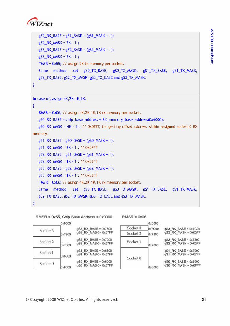
© Copyright 2008 WIZnet Co., Inc. All rights reserved. 38
W5100 D
atasheet
gS2_RX_BASE = gS1_BASE + (gS1_MASK + 1);
gS2_RX_MASK = 2K – 1 ;
gS3_RX_BASE = gS2_BASE + (gS2_MASK + 1);
gS3_RX_MASK = 2K – 1 ;
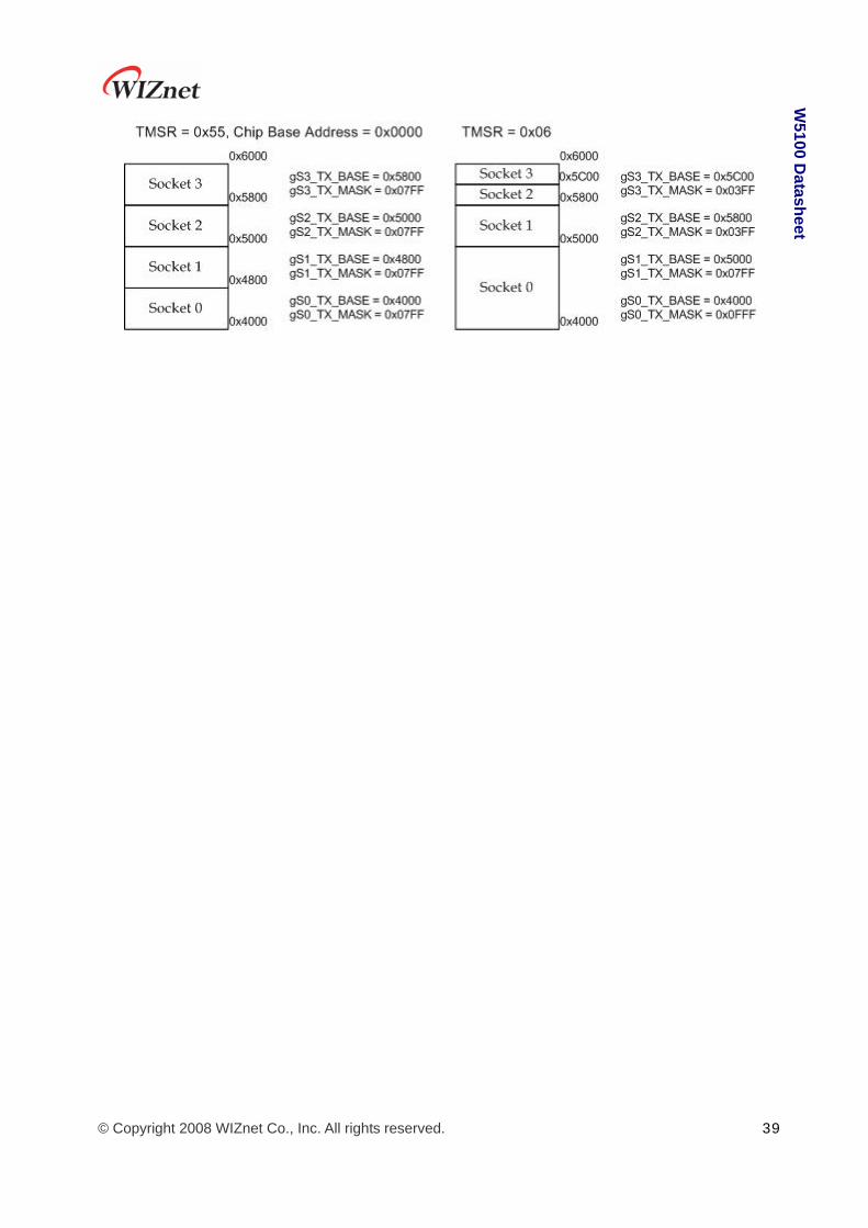
TMSR = 0x55; // assign 2K tx memory per socket.
Same method, set gS0_TX_BASE, gS0_TX_MASK, gS1_TX_BASE, gS1_TX_MASK,
gS2_TX_BASE, gS2_TX_MASK, gS3_TX_BASE and gS3_TX_MASK.
}
In case of, assign 4K,2K,1K,1K.
{
RMSR = 0x06; // assign 4K,2K,1K,1K rx memory per socket.
gS0_RX_BASE = chip_base_address + RX_memory_base_address(0x6000);
gS0_RX_MASK = 4K – 1 ; // 0x0FFF, for getting offset address within assigned socket 0 RX
memory.
gS1_RX_BASE = gS0_BASE + (gS0_MASK + 1);
gS1_RX_MASK = 2K – 1 ; // 0x07FF
gS2_RX_BASE = gS1_BASE + (gS1_MASK + 1);
gS2_RX_MASK = 1K – 1 ; // 0x03FF
gS3_RX_BASE = gS2_BASE + (gS2_MASK + 1);
gS3_RX_MASK = 1K – 1 ; // 0x03FF
TMSR = 0x06; // assign 4K,2K,1K,1K rx memory per socket.
Same method, set gS0_TX_BASE, gS0_TX_MASK, gS1_TX_BASE, gS1_TX_MASK,
gS2_TX_BASE, gS2_TX_MASK, gS3_TX_BASE and gS3_TX_MASK.
}
© Copyright 2008 WIZnet Co., Inc. All rights reserved. 39
W5100 D
atasheet

© Copyright 2008 WIZnet Co., Inc. All rights reserved. 40
W5100 D
atasheet
5.2 Data Communications
Data communication is available through TCP, UDP, IP-Raw and MAC-Raw . In order to select it,
configure protocol field of Socket n Mode Register(Sn_MR) of the communication sockets
(W5100 supports total 4 sockets).
5.2.1 TCP TCP is the connection based communication method that will establish connection in advance
and deliver the data through the connection by using IP Address and Port number of the
systems. There are two methods to establish the connection. One is SERVER mode(passive
open) that is waiting for connection request. The other is CLIENT mode (active open) that
sends connection request to a server.

© Copyright 2008 WIZnet Co., Inc. All rights reserved. 41
W5100 D
atasheet
5.2.1.1 SERVER mode
Socket Initialization
In order to initialize a socket, set the operation mode and port of the socket, and provide
OPEN command to the command register of the socket. Below is the registers related.
Socket n Mode Register (Sn_MR)
Socket n Source Port Register (Sn_PORT)
Socket n Command Register (Sn_CR)
It initializes the socket n as TCP,
{
START:
/* sets TCP mode */
Sn_MR = 0x01;
/* sets source port number */
Sn_PORT = source_port;
© Copyright 2008 WIZnet Co., Inc. All rights reserved. 42
W5100 D
atasheet
/* sets OPEN command */
Sn_CR = OPEN;
if (Sn_SR != SOCK_INIT) Sn_CR = CLOSE; goto START;
}
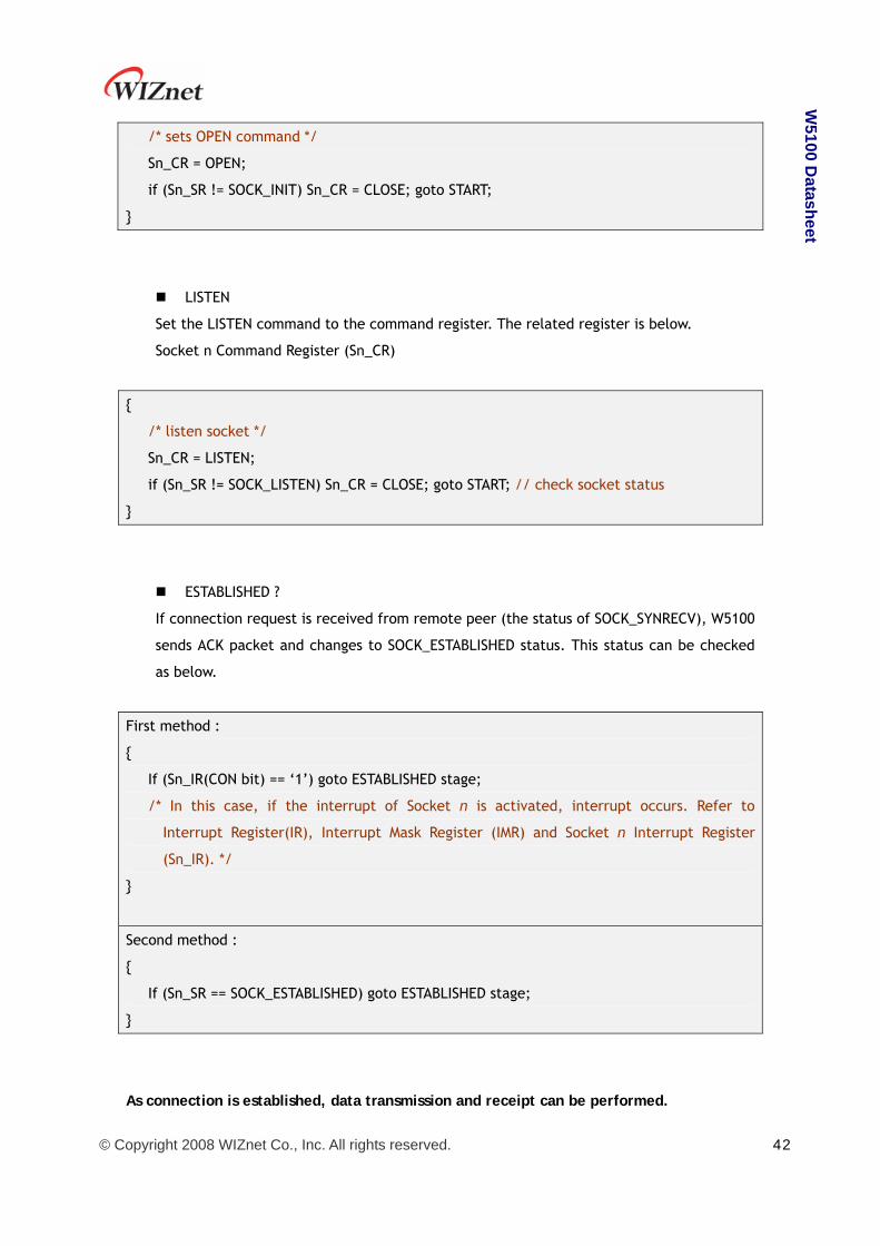
LISTEN
Set the LISTEN command to the command register. The related register is below.
Socket n Command Register (Sn_CR)
{
/* listen socket */
Sn_CR = LISTEN;
if (Sn_SR != SOCK_LISTEN) Sn_CR = CLOSE; goto START; // check socket status
}
ESTABLISHED ?
If connection request is received from remote peer (the status of SOCK_SYNRECV), W5100
sends ACK packet and changes to SOCK_ESTABLISHED status. This status can be checked
as below.
First method :
{
If (Sn_IR(CON bit) == ‘1’) goto ESTABLISHED stage;
/* In this case, if the interrupt of Socket n is activated, interrupt occurs. Refer to
Interrupt Register(IR), Interrupt Mask Register (IMR) and Socket n Interrupt Register
(Sn_IR). */
}
Second method :
{
If (Sn_SR == SOCK_ESTABLISHED) goto ESTABLISHED stage;
}
As connection is established, data transmission and receipt can be performed.

© Copyright 2008 WIZnet Co., Inc. All rights reserved. 43
W5100 D
atasheet
ESTABLISHED : Received Data ?
Check as below to know if data is received from remote peer or not.
First method :
{
If (Sn_IR(RECV bit) == ‘1’) goto Receiving Process stage;
/* In this case, if the interrupt of Socket n is activated, interrupt occurs. Refer to
Interrupt Register(IR), Interrupt Mask Register (IMR) and Socket n Interrupt Register
(Sn_IR). */
}
Second Method :
{
if (Sn_RX_RSR != 0x0000) goto Receiving Process stage;
}
ESTABLISHED : Receiving Process
Received data can be processed as below.
{
/* first, get the received size */
get_size = Sn_RX_RSR;
/* calculate offset address */
get_offset = Sn_RX_RD & gSn_RX_MASK;
/* calculate start address(physical address) */
get_start_address = gSn_RX_BASE + get_offset;
/* if overflow socket RX memory */
if ( (get_offset + get_size) > (gSn_RX_MASK + 1) )
{
/* copy upper_size bytes of get_start_address to destination_addr */
upper_size = (gSn_RX_MASK + 1) – get_offset;
memcpy(get_start_address, destination_addr, upper_size);
/* update destination_addr*/
destination_addr += upper_size;
/* copy left_size bytes of gSn_RX_BASE to destination_addr */
left_size = get_size – upper_size;

© Copyright 2008 WIZnet Co., Inc. All rights reserved. 44
W5100 D
atasheet
memcpy(gSn_RX_BASE, destination_addr, left_size);
}
else
{
/* copy get_size bytes of get_start_address to destination_addr */
memcpy(get_start_address, destination_addr, get_size);
}
/* increase Sn_RX_RD as length of get_size */
Sn_RX_RD += get_size;
/* set RECV command */
Sn_CR = RECV;
}
ESTABLISHED : Send DATA ? / Sending Process
The sending procedure is as below.
{
/* first, get the free TX memory size */
FREESIZE:
get_free_size = Sn_TX_FSR;
if (get_free_size < send_size) goto FREESIZE;
/* calculate offset address */
get_offset = Sn_TX_WR & gSn_TX_MASK;
/* calculate start address(physical address) */
get_start_address = gSn_TX_BASE + get_offset;
/* if overflow socket TX memory */
if ( (get_offset + send_size) > (gSn_TX_MASK + 1) )
{
/* copy upper_size bytes of source_addr to get_start_address */
upper_size = (gSn_TX_MASK + 1) – get_offset;
memcpy(source_addr, get_start_address, upper_size);
/* update source_addr*/
source_addr += upper_size;
/* copy left_size bytes of source_addr to gSn_TX_BASE */
left_size = send_size – upper_size;

© Copyright 2008 WIZnet Co., Inc. All rights reserved. 45
W5100 D
atasheet
memcpy(source_addr, gSn_TX_BASE, left_size);
}
else
{
/* copy send_size bytes of source_addr to get_start_address */
memcpy(source_addr, get_start_address, send_size);
}
/* increase Sn_TX_WR as length of send_size */
Sn_TX_WR += send_size;
/* set SEND command */
Sn_CR = SEND;
}
ESTABLISHED : Received FIN?
Waiting for a connection termination request from remote peer.
It can be checked as below if it received connection termination request of remote peer.
First method :
{
If (Sn_IR(DISCON bit) == ‘1’) goto CLOSED stage;
/* In this case, if the interrupt of Socket n is activated, interrupt occurs. Refer to
Interrupt Register(IR), Interrupt Mask Register (IMR) and Socket n Interrupt Register
(Sn_IR). */
}
Second method :
{
If (Sn_SR == SOCK_CLOSE_WAIT) goto CLOSED stage;
}
ESTABLISHED : Disconnect ? / Disconnecting Process
Check if user requests to terminate this connection.
To terminate the connection, proceed as below,
{
/* set DISCON command */
Sn_CR = DISCON;
}

© Copyright 2008 WIZnet Co., Inc. All rights reserved. 46
W5100 D
atasheet
ESTABLISHED : CLOSED ?
No connection state at all. It can be checked as below,
First method :
{
If (Sn_IR(DISCON bit) == ‘1’) goto CLOSED stage;
/* In this case, if the interrupt of Socket n is activated, interrupt occurs. Refer to
Interrupt Register(IR), Interrupt Mask Register (IMR) and Socket n Interrupt Register
(Sn_IR). */
}
Second method :
{
If (Sn_SR == SOCK_CLOSED) goto CLOSED stage;
}
ESTABLISHED : Timeout
In case that connection is closed due to the error of remote peer during data receiving or
connection closing process, data transmission can not be normally processed. At this time
Timeout occurs after some time.
First method :
{
If (Sn_IR(TIMEOUT bit) == ‘1’) goto CLOSED stage;
/* In this case, if the interrupt of Socket n is activated, interrupt occurs. Refer to
Interrupt Register(IR), Interrupt Mask Register (IMR) and Socket n Interrupt Register
(Sn_IR). */
}
Second method :
{
If (Sn_SR == SOCK_CLOSED) goto CLOSED stage;
}

© Copyright 2008 WIZnet Co., Inc. All rights reserved. 47
W5100 D
atasheet
Socket Close
This process should be processed in case that connection is closed after data exchange,
socket should be closed with Timeout occurrence, or forcible disconnection is necessary
due to abnormal operation.
{
/* set CLOSE command */
Sn_CR = CLOSE;
}

© Copyright 2008 WIZnet Co., Inc. All rights reserved. 48
W5100 D
atasheet
5.2.1.2 CLIENT mode
Whole process is shown as below.
Socket Initialization
Refer to “5.2.1.1 SERVER mode” (The operation is same as SERVER).
CONNECT
Send connection request to remote HOST(SERVER) is as below.
{
/* Write the value of server_ip, server_port to the Socket n Destination IP Address
Register(Sn_DIPR), Socket n Destination Port Register(Sn_DPORT). */
Sn_DIPR = server_ip;
Sn_DPORT = server_port;
/* set CONNECT command */

© Copyright 2008 WIZnet Co., Inc. All rights reserved. 49
W5100 D
atasheet
Sn_CR = CONNECT;
}
ESTABLISHED ?
The connection is established. It can be checked as below,
First method :
{
If (Sn_IR(CON bit) == ‘1’) goto ESTABLISHED stage;
/* In this case, if the interrupt of Socket n is activated, interrupt occurs. Refer to
Interrupt Register(IR), Interrupt Mask Register (IMR) and Socket n Interrupt Register
(Sn_IR). */
}
Second method :
{
If (Sn_SR == SOCK_ESTABLISHED) goto ESTABLISHED stage;
}
Timeout
Socket is closed as Timeout occurs as there is not response from remote peer. It can be
checked as below.
First method :
{
If (Sn_IR(TIMEOUT bit) == ‘1’) goto CLOSED stage;
/* In this case, if the interrupt of Socket n is activated, interrupt occurs. Refer to
Interrupt Register(IR), Interrupt Mask Register (IMR) and Socket n Interrupt Register
(Sn_IR). */
}
Second method :
{
If (Sn_SR == SOCK_CLOSED) goto CLOSED stage;
}
ESTABLISHED
Refer to “5.2.1.1. SERVER mode” (The operation is same as SERVER mode)
© Copyright 2008 WIZnet Co., Inc. All rights reserved. 50
W5100 D
atasheet
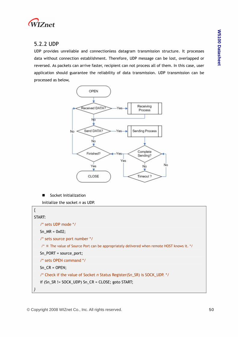
5.2.2 UDP UDP provides unreliable and connectionless datagram transmission structure. It processes
data without connection establishment. Therefore, UDP message can be lost, overlapped or
reversed. As packets can arrive faster, recipient can not process all of them. In this case, user
application should guarantee the reliability of data transmission. UDP transmission can be
processed as below,
Socket Initialization
Initialize the socket n as UDP.
{
START:
/* sets UDP mode */
Sn_MR = 0x02;
/* sets source port number */
/* ※ The value of Source Port can be appropriately delivered when remote HOST knows it. */
Sn_PORT = source_port;
/* sets OPEN command */
Sn_CR = OPEN;
/* Check if the value of Socket n Status Register(Sn_SR) is SOCK_UDP. */
if (Sn_SR != SOCK_UDP) Sn_CR = CLOSE; goto START;
}

© Copyright 2008 WIZnet Co., Inc. All rights reserved. 51
W5100 D
atasheet
Received DATA?
It can be checked as below if data is received from remote peer.
First method :
{
if (Sn_RX_RSR != 0x0000) goto Receiving Process stage;
}
Second Method :
{
If (Sn_IR(RECV bit) == ‘1’) goto Receiving Process stage;
/* In this case, if the interrupt of Socket n is activated, interrupt occurs. Refer to
Interrupt Register(IR), Interrupt Mask Register (IMR) and Socket n Interrupt Register
(Sn_IR). */
}
Receiving Process
Received data can be processed as below. In case of UDP, 8byte header is attached to
receiving data. The structure of the header is as below.
{
/* first, get the received size */
get_size = Sn_RX_RSR;
/* calculate offset address */
get_offset = Sn_RX_RD & gSn_RX_MASK;
/* calculate start address(physical address) */
get_start_address = gSn_RX_BASE + get_offset;
/* read head information (8 bytes) */
header_size = 8;
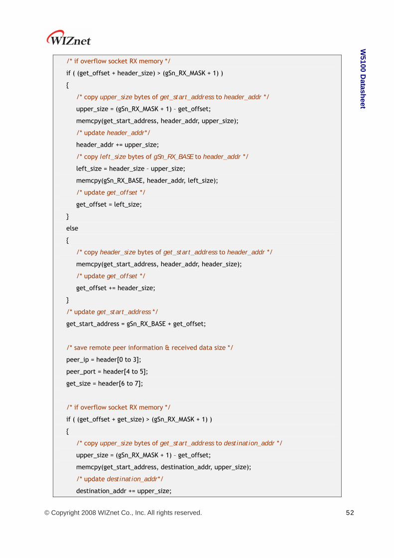
© Copyright 2008 WIZnet Co., Inc. All rights reserved. 52
W5100 D
atasheet
/* if overflow socket RX memory */
if ( (get_offset + header_size) > (gSn_RX_MASK + 1) )
{
/* copy upper_size bytes of get_start_address to header_addr */
upper_size = (gSn_RX_MASK + 1) – get_offset;
memcpy(get_start_address, header_addr, upper_size);
/* update header_addr*/
header_addr += upper_size;
/* copy left_size bytes of gSn_RX_BASE to header_addr */
left_size = header_size – upper_size;
memcpy(gSn_RX_BASE, header_addr, left_size);
/* update get_offset */
get_offset = left_size;
}
else
{
/* copy header_size bytes of get_start_address to header_addr */
memcpy(get_start_address, header_addr, header_size);
/* update get_offset */
get_offset += header_size;
}
/* update get_start_address */
get_start_address = gSn_RX_BASE + get_offset;
/* save remote peer information & received data size */
peer_ip = header[0 to 3];
peer_port = header[4 to 5];
get_size = header[6 to 7];
/* if overflow socket RX memory */
if ( (get_offset + get_size) > (gSn_RX_MASK + 1) )
{
/* copy upper_size bytes of get_start_address to destination_addr */
upper_size = (gSn_RX_MASK + 1) – get_offset;
memcpy(get_start_address, destination_addr, upper_size);
/* update destination_addr*/
destination_addr += upper_size;

© Copyright 2008 WIZnet Co., Inc. All rights reserved. 53
W5100 D
atasheet
/* copy left_size bytes of gSn_RX_BASE to destination_addr */
left_size = get_size – upper_size;
memcpy(gSn_RX_BASE, destination_addr, left_size);
}
else
{
/* copy get_size bytes of get_start_address to destination_addr */
memcpy(get_start_address, destination_addr, get_size);
}
/* increase Sn_RX_RD as length of get_size+header_size */
Sn_RX_RD = Sn_RX_RD + get_size + header_size;
/* set RECV command */
Sn_CR = RECV;
}
Send Data? / Sending Process
Data transmission process is as below.
{
/* first, get the free TX memory size */
FREESIZE:
get_free_size = Sn_TX_FSR;
if (get_free_size < send_size) goto FREESIZE;
/* Write the value of remote_ip, remote_port to the Socket n Destination IP Address
Register(Sn_DIPR), Socket n Destination Port Register(Sn_DPORT). */
Sn_DIPR = remote_ip;
Sn_DPORT = remote_port;
/* calculate offset address */
get_offset = Sn_TX_WR & gSn_TX_MASK;
/* calculate start address(physical address) */
get_start_address = gSn_TX_BASE + get_offset;
/* if overflow socket TX memory */
if ( (get_offset + send_size) > (gSn_TX_MASK + 1) )
{

© Copyright 2008 WIZnet Co., Inc. All rights reserved. 54
W5100 D
atasheet
/* copy upper_size bytes of source_addr to get_start_address */
upper_size = (gSn_TX_MASK + 1) – get_offset;
memcpy(source_addr, get_start_address, upper_size);
/* update source_addr*/
source_addr += upper_size;
/* copy left_size bytes of source_addr to gSn_TX_BASE */
left_size = send_size – upper_size;
memcpy(source_addr, gSn_TX_BASE, left_size);
}
else
{
/* copy send_size bytes of source_addr to get_start_address */
memcpy(source_addr, get_start_address, send_size);
}
/* increase Sn_TX_WR as length of send_size */
Sn_TX_WR += send_size;
/* set SEND command */
Sn_CR = SEND;
}
Complete Sending?
The sending completion should be checked after SEND command.
{
If (Sn_CR == 0x00) transmission is completed.
}
Timeout
Timeout occurs if remote peer does not exist or data transmission is not normally
processed. It can be checked as below.
{
If (Sn_IR(TIMEOUT bit) == ‘1’) goto next stage;
/* In this case, if the interrupt of Socket n is activated, interrupt occurs. Refer to
Interrupt Register(IR), Interrupt Mask Register (IMR) and Socket n Interrupt Register
(Sn_IR). */
}
© Copyright 2008 WIZnet Co., Inc. All rights reserved. 55
W5100 D
atasheet
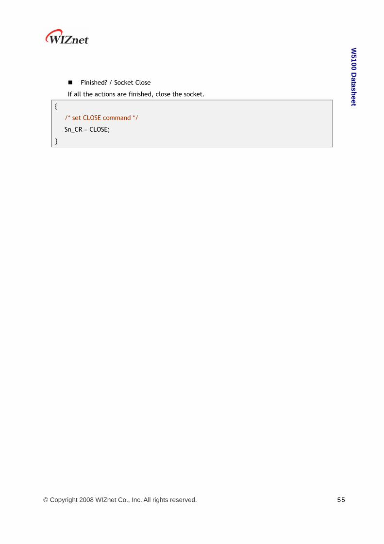
Finished? / Socket Close
If all the actions are finished, close the socket.
{
/* set CLOSE command */
Sn_CR = CLOSE;
}

© Copyright 2008 WIZnet Co., Inc. All rights reserved. 56
W5100 D
atasheet
5.2.3 IP raw
IP Raw mode can be utilized if transport layer protocol of some ICMP or IGMP that W5100 does
not support, needs to be processed.
Socket Initialization
It initializes the socket as IP raw.
{
START:
/* sets IP raw mode */
Sn_MR = 0x03;
/* sets Protocol value */
/* The value of Protocol is used in Protocol Field of IP Header.
For the list of protocol identification number of upper classification, refer to on line
documents of IANA (http://www.iana.org/assignments/protocol-numbers). */
Sn_PROTO = protocol_value;
/* sets OPEN command */
Sn_CR = OPEN;
/* Check if the value of Socket n Status Register(Sn_SR) is SOCK_IPRAW. */
if (Sn_SR != SOCK_IPRAW) Sn_CR = CLOSE; goto START;
}

© Copyright 2008 WIZnet Co., Inc. All rights reserved. 57
W5100 D
atasheet
Received DATA?
It is same as UDP. Refer to “5.2.2 UDP”.
Receiving Process
This is same as UDP. Refer to “5.2.2 UDP” except the header information and header size.
In case of IP raw, 6byte header is attached to the data received. The header structure is
as below.
Send DATA? / Sending Process
This is same as UDP. Refer to “5.2.2 UDP” except that remote_port information is not
needed.
Complete Sending
Timeout
Finished? / Socket Closed
Next actions are same as UDP. Refer to “5.2.2 UDP”.
5.2.4 MAC raw
MAC Raw mode(only supported in socket 0) can be utilized.
Socket Initialization
It initializes the socket as MAC raw.
{
START:
/* sets MAC raw mode */

© Copyright 2008 WIZnet Co., Inc. All rights reserved. 58
W5100 D
atasheet
Sn_MR = 0x04;
/* sets OPEN command */
Sn_CR = OPEN;
/* Check if the value of Socket n Status Register(Sn_SR) is SOCK_MACRAW. */
if (Sn_SR != SOCK_MACRAW) Sn_CR = CLOSE; goto START;
}
Received DATA?
This is same as UDP. Refer to “5.2.2 UDP”.
Receiving Process
MAC raw received Ethernet packet having packet size information.
In case of MAC raw, 2byte header is attached to the data received. The header structure
is as below.
Send DATA? / Sending Process
This is same as UDP. Refer to “5.2.2 UDP” except that remote_port information is not
needed.

© Copyright 2008 WIZnet Co., Inc. All rights reserved. 59
W5100 D
atasheet
6. Application Information For the communication with MCU, W5100 provides Direct, Indirect Bus I/F, and SPI I/F modes.
For the communication with Ethernet PHY, MII is used.
6.1 Direct Bus Interface mode
Direct Bus I/F mode uses 15bit address line and 8bit data line, /CS, /RD, /WR, /INT.
6.2 Indirect Bus Interface mode
Indirect Bus I/F mode uses 2bit address line and 8bit data line, /CS, /RD, /WR, /INT.
[14:2], other address lines should process Pull-down.
Indirect bus I/F mode related register is as below.
© Copyright 2008 WIZnet Co., Inc. All rights reserved. 60
W5100 D
atasheet
Value Symbol Description
0x00 MR
It performs the selection of Indirect bus I/F mode, address
automatic increase. Refer to “4. Register Description” for more
detail.
0x01
0x02
IDM_AR0
IDM_AR1
Indirect bus I/F mode address Register
Big-endian use only
· In case of Big-endian ordering
0x01 0x02
IDM_AR0 : MSB IDM_AR1 : LSB
Ex) In case of reading S0_CR(0x0401),
0x01(IDM_AR0) 0x02(IDM_AR1)
0x04 0x01 0x03 IDM_DR Indirect bus I/F mode data Register
In order to read or write the internal register or internal TX/RX Memory,
1. Write the address to read or write on IDM_AR0, 1.
2. Read or Write IDM_DR.
In order to read or write the data on the sequential address, set AI bit of MR(Mode Register).
With this, user performs above 1 only one time. Whenever read or write IDM_DR, IDM_AR , the
value is automatically increased by 1. Therefore, the value can be processed on the
sequential address just by continuous reading or writing of IDM_DR.
6.3 SPI (Serial Peripheral Interface) mode
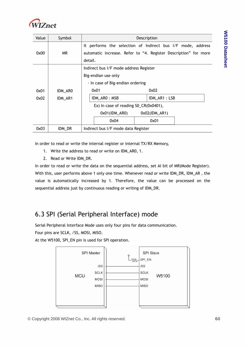
Serial Peripheral Interface Mode uses only four pins for data communication.
Four pins are SCLK, /SS, MOSI, MISO.
At the W5100, SPI_EN pin is used for SPI operation.

© Copyright 2008 WIZnet Co., Inc. All rights reserved. 61
W5100 D
atasheet
6.3.1 Device Operations The W5100 is controlled by a set of instruction that is sent from a host controller, commonly
referred to as the SPI Master. The SPI Master communicates with W5100 via the SPI bus which
is composed of four signal lines: Slave Select(/SS), Serial Clock(SCLK), MOSI(Master Out Slave
In), MISO(Master In Slave Out).
The SPI protocol defines four modes for its operation (Mode 0, 1, 2, 3). Each mode differs
according to the SCLK polarity and phase - how the polarity and phase control the flow of
data on the SPI bus.
The W5100 operates as SPI Slave device and supports the most common modes - SPI Mode 0
and 3.
The only difference between SPI Mode 0 and 3 is the polarity of the SCLK signal at the
inactive state. With SPI Mode 0 and 3, data is always latched in on the rising edge of SCLK and
always output on the falling edge of SCLK.
6.3.2 Commands According to SPI protocol, there are only two data lines used between SPI devices. So, it is
necessary to define OP-Code. W5100 uses two types of OP-Code - Read OP-Code and Write
OP-Code. Except for those two OP-Codes, W5100 will be ignored and no operation will be
started.
In SPI Mode, W5100 operates in “unit of 32-bit stream”.
The unit of 32-bit stream is composed of 1 byte OP-Code Field, 2 bytes Address Field and 1
byte data Field.
OP-Code, Address and data bytes are transferred with the most significant bit(MSB) first and
least significant bit(LSB) last. In other words, the first bit of SPI data is MSB of OP-Code Field
and the last bit of SPI data is LSB of Data-Field. W5100 SPI data format is as below.
Command OP-Code Field Address Field Data Field
Write operation 0xF0 1111 0000 2 bytes 1 byte
Read operation 0x0F 0000 1111 2 bytes 1 byte
6.3.3 Process of using general SPI Master device (According to SPI protocol)

© Copyright 2008 WIZnet Co., Inc. All rights reserved. 62
W5100 D
atasheet
1. Configure Input/Output direction on SPI Master device pins.
* /SS (Slave Select) : Output pin
* SCLK (Serial Clock) : Output pin
* MOSI (Master Out Slave In) : Output pin
* MISO (Master In Slave Out) : Input pin
2. Configure /SS as ‘High’
3. Configure the registers on SPI Master device.
* SPI Enable bit on SPCR register (SPI Control Register)
* Master/Slave select bit on SPCR register
* SPI Mode bit on SPCR register
* SPI data rate bit on SPCR register and SPSR register (SPI State Register)
4. Write desired value for transmission on SPDR register (SPI Data Register).
5. Configure /SS as ‘Low’ (data transfer start)
6. Wait for reception complete
7. If all data transmission ends, configure /SS as ‘High’
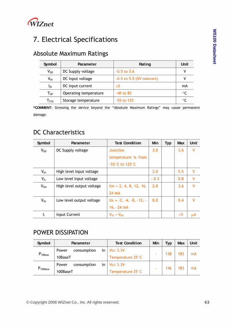
© Copyright 2008 WIZnet Co., Inc. All rights reserved. 63
W5100 D
atasheet
7. Electrical Specifications
Absolute Maximum Ratings
Symbol Parameter Rating Unit
VDD DC Supply voltage -0.5 to 3.6 V
VIN DC input voltage -0.5 to 5.5 (5V tolerant) V
IIN DC input current ±5 mA
TOP Operating temperature -40 to 85 °C
TSTG Storage temperature -55 to 125 °C
*COMMENT: Stressing the device beyond the “Absolute Maximum Ratings” may cause permanent
damage.
DC Characteristics
Symbol Parameter Test Condition Min Typ Max Unit
VDD DC Supply voltage Junction
temperature is from
-55°C to 125°C
3.0 3.6 V
VIH High level input voltage 2.0 5.5 V
VIL Low level input voltage - 0.5 0.8 V
VOH High level output voltage IOH = 2, 4, 8, 12, 16,
24 mA
2.0 3.6 V
VOL Low level output voltage IOL = -2, -4, -8, -12, -
16, -24 mA
0.0 0.4 V
II Input Current VIN = VDD ±5 µA
POWER DISSIPATION
Symbol Parameter Test Condition Min Typ Max Unit
P10Base
Power consumption in
10BaseT
Vcc 3.3V
Temperature 25°C - 138 183 mA
P100Base
Power consumption in
100BaseT
Vcc 3.3V
Temperature 25°C - 146 183 mA

© Copyright 2008 WIZnet Co., Inc. All rights reserved. 64
W5100 D
atasheet
AC Characteristics
Reset Timing
Description Min Max
1 Reset Cycle Time 2 us -
2 /RESET to internal PLOCK - 10 ms
Register/Memory READ Timing
Description Min Max
1 Read Cycle Time 80 ns -
2 Valid Address to /CS low time 8 ns -
3 /CS low to /RD low time - 1 ns
4 /RD high to /CS high time - 1 ns
5 /RD low to Valid Data Output time - 80 ns
6 /RD high to Data High-Z Output time - 1 ns

© Copyright 2008 WIZnet Co., Inc. All rights reserved. 65
W5100 D
atasheet
Register/Memory WRITE Timing
Description Min Max
1 Write Cycle Time 70 ns -
2 Valid Address to /CS low time 7 ns -
3 /CS low to /WR high time 70 ns -
4 /CS low to /WR low time - 1 ns
5 /WR high to /CS high time - 1 ns
6 /WR low to Valid Data time - 14 ns
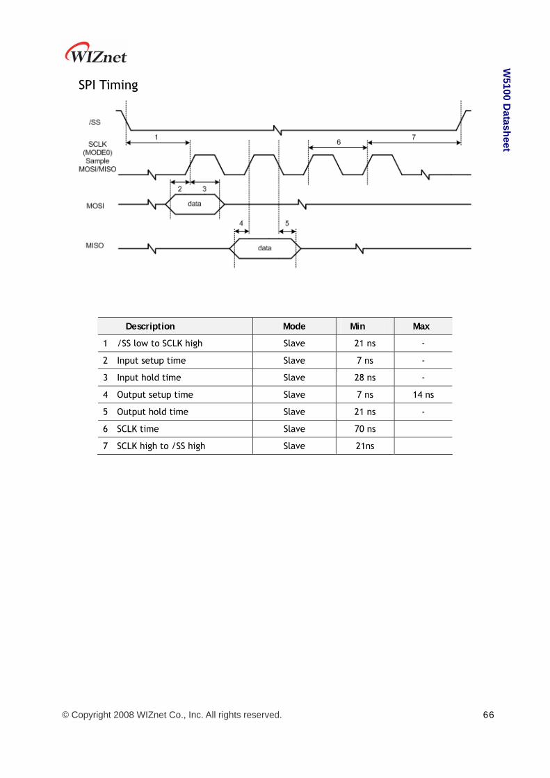
© Copyright 2008 WIZnet Co., Inc. All rights reserved. 66
W5100 D
atasheet
SPI Timing
Description Mode Min Max
1 /SS low to SCLK high Slave 21 ns -
2 Input setup time Slave 7 ns -
3 Input hold time Slave 28 ns -
4 Output setup time Slave 7 ns 14 ns
5 Output hold time Slave 21 ns -
6 SCLK time Slave 70 ns
7 SCLK high to /SS high Slave 21ns
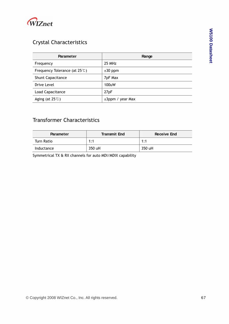
© Copyright 2008 WIZnet Co., Inc. All rights reserved. 67
W5100 D
atasheet
Crystal Characteristics
Parameter Range
Frequency 25 MHz
Frequency Tolerance (at 25 )℃ ±30 ppm
Shunt Capacitance 7pF Max
Drive Level 100uW
Load Capacitance 27pF
Aging (at 25 )℃ ±3ppm / year Max
Transformer Characteristics
Parameter Transmit End Receive End
Turn Ratio 1:1 1:1
Inductance 350 uH 350 uH
Symmetrical TX & RX channels for auto MDI/MDIX capability

© Copyright 2008 WIZnet Co., Inc. All rights reserved. 68
W5100 D
atasheet
8. IR Reflow Temperature Profile (Lead-Free)
Moisture Sensitivity Level : 3
Dry Pack Required : Yes
Average Ramp-Up Rate
(Tsmax to Tp)
3° C/second max.
Preheat
– Temperature Min (Tsmin)
– Temperature Max (Tsmax)
– Time (tsmin to tsmax)
150 °C
200 °C
60-180 seconds
Time maintained above:
– Temperature (TL)
– Time (tL)
217 °C
60-150 seconds
Peak/Classification Temperature (Tp) 260 + 0 °C
Time within 5 °C of actual Peak Temperature (tp) 20-40 seconds
Ramp-Down Rate 6 °C/second max.
Time 25 °C to Peak Temperature 8 minutes max.

© Copyright 2008 WIZnet Co., Inc. All rights reserved. 69
W5100 D
atasheet
9. Package Descriptions
☞ Above diagram shows PIN dimension. All 80 pins are not displayed.
MILLIMETER INCH SYMBOL
MIN. NOM. MAX. MIN. NOM. MAX.
A - - 1.60 - - 0.063
A1 0.05 - 0.15 0.002 - 0.006

© Copyright 2008 WIZnet Co., Inc. All rights reserved. 70
W5100 D
atasheet
A2 1.35 1.40 1.45 0.053 0.055 0.057
D 12.00 BSC. 0.472 BSC.
D1 10.00 BSC. 0.393 BSC.
E 12.00 BSC. 0.472 BSC.
E1 10.00 BSC. 0.393 BSC.
R2 0.08 - 0.20 0.003 - 0.008
R1 0.08 - - 0.003 - -
θ 0° 3.5° 7° 0° 3.5° 7°
θ1 0° - - 0° - -
θ2 11° 12° 13° 11° 12° 13°
θ3 11° 12° 13° 11° 12° 13°
c 0.09 - 0.20 0.004 - 0.008
L 0.45 0.60 0.75 0.018 0.024 0.030
L1 1.00 REF 0.039 REF
S 0.20 - - 0.008 - -
b 0.13 0.16 0.23 0.005 0.006 0.009
e 0.40 BSC 0.016 BSC
D2 7.60 0.299
E2 7.60 0.299
aaa 0.20 0.008
bbb 0.20 0.008
ccc 0.08 0.003
ddd 0.07 0.003
Note :
1. DIMENSIONS D1 AND E1 DO NOT INCLUDE MOLD PROTRUSION.
ALLOWABLE PROTRUSION IS 0.25mm PER SIDE. D1 AND E1 ARE MAXIMUM PLASTIC BODY
SIZE DIMENSIONS INCLUDING MOLD MISMATCH.
2. DIMENSION b DOES NOT INCLUDE DAMBAR PROTRUSION.
ALLOWABLE DAMBAR PROTRUSION SHALL NOT CAUSE THE LEAD WIDTH TO EXCEED THE
MAXIMUM b DIMENSION BY MORE THAN 0.08mm.
DAMBAR CAN NOT BE LOCATED ON THE LOWER RADIUS OR THE FOOT. MINIMUM SPACE
BETWEEN PROTRUSION AND AN ADJACENT LEAD IS 0.07mm FOR 0.4mm AND 0.5mm
PITCH PACKAGES.


![W5100 Datasheet · /WR I 57 WRITE ENABLE Strobe from MCU to write an internal register/memory selected by ADDR[14:0]. Data is latched into the W5100 on the rising edge of this input.](https://static.fdocuments.in/doc/165x107/5f7115bf1ca8fb558204eab4/w5100-datasheet-wr-i-57-write-enable-strobe-from-mcu-to-write-an-internal-registermemory.jpg)


