W450656C 11 - Boom Trucksgiuffre.com/manuals/greer/terex_BT510/W450656C.pdf · Extension Sensor ....
66
OPERATOR’S MANUAL BT 510 W450656C 11/11
Transcript of W450656C 11 - Boom Trucksgiuffre.com/manuals/greer/terex_BT510/W450656C.pdf · Extension Sensor ....

OPERATOR’S MANUAL
BT 510
W450656C 11/11

2 W450656C Rev 11/11
TABLE OF CONTENTS Introduction...........................................................................................................................................................5 System Components.............................................................................................................................................5 Display Console....................................................................................................................................................7 Operator Console......................................................................................................................................9 Operation.................................................................................................................................................10 Power Up Self-Test.....................................................................................................................10 Adjust Brightness and Contrast...................................................................................................10 Outriggers/Outrigger Position Sensing........................................................................................11 Stowing the Jib............................................................................................................................11 Erecting the Stowed Jib...............................................................................................................11 Basket Operation.........................................................................................................................12 Setting the Parts of Line..............................................................................................................12 Cancel Alarm Key........................................................................................................................12 Reset Function Kick-out..............................................................................................................13 Operator Programmable Alarms.............................................................................................................14 Setting the Minimum/Maximum Boom Angle Alarm....................................................................14 Setting the Maximum Boom Length Alarm..................................................................................15 Setting the Maximum Tip Height Alarm.......................................................................................15 Accessing the Swing and Work Area Alarms..............................................................................16 Setting the Left and Right Swing Alarms.....................................................................................16 Setting the Work Area Alarm.......................................................................................................17 Zeroing the Swing Sensor...........................................................................................................19 Calibration...........................................................................................................................................................20
Entering Calibration Mode.......................................................................................................................21 Number Entry..............................................................................................................................21
Extension Sensor Setup..........................................................................................................................22 Extension Sensor Physical Zero.............................................................................................................22 Extension Sensor Zero Calibration..........................................................................................................22 Angle Sensor Setup................................................................................................................................23 Angle Sensor Physical Zero....................................................................................................................23 Angle Sensor Zero Calibration................................................................................................................23 Spanning the Extension and Angle Sensors...........................................................................................24 Entering the Span....................................................................................................................................24 Swing Sensor Setup................................................................................................................................25
Zeroing the Swing Sensor...........................................................................................................26 Direction of Swing........................................................................................................................26
Outrigger Position Sensing......................................................................................................................26 System Diagram......................................................................................................................................27 Troubleshooting..................................................................................................................................................28 System Self-Test.....................................................................................................................................28 Error Codes.............................................................................................................................................29
Viewing Error Codes....................................................................................................................29 Group “A” Error Codes................................................................................................................30 Group “B” Error Codes................................................................................................................31 Group “C” Error Codes................................................................................................................32 Group “D” Error Codes................................................................................................................33 “No Fault Code” Problems.......................................................................................................................33

3 W450656C Rev 11/11
Anti-Two-Block Alarm (ATB)........................................................................................................33 Displayed Load or Radius Errors.................................................................................................34 Checking the Boom Extension.........................................................................................34 Checking the Main Boom Radius....................................................................................34 Checking the Boom Angle...............................................................................................34 Checking the Pressure Sensors......................................................................................34 Computer Unit.........................................................................................................................................36 Computer Unit Layout..................................................................................................................37 Internal Status Indicators.............................................................................................................38 The COMM Indicator (A450625 Computer only).........................................................................40 Replacing the Computer Unit......................................................................................................40 Computer Unit Replaceable Parts...........................................................................................................41 System Chip (IC16).....................................................................................................................41 Removing the Existing System or Communications Chip...........................................................41 Installing the Replacement System or Communications Chip.....................................................42
Communications Chips (A450625 only)......................................................................................42 Function Kick-out Fuse (A450625 only)......................................................................................42 Circuit Breaker Protection (A450656 only)..................................................................................42
Replacing the Circuit Breaker......................................................................................................42 Computer Wiring Harnesses...................................................................................................................43 Display Unit Connector................................................................................................................43 Reeling Drum Connector.............................................................................................................43 Pressure Sensors....................................................................................................................................44 Checking the Pressure Sensors..................................................................................................44 Display Console......................................................................................................................................45 Display Console Problems..........................................................................................................45
Checking the Display Console.....................................................................................................46 Replacing the Display Console....................................................................................................46
Extension Reel........................................................................................................................................48 Checking the Reeling Drum Cable Layering...............................................................................49 Extension Sensor....................................................................................................................................50 Extension Sensor Physical Zero..................................................................................................50 Extension Sensor Zero Calibration..............................................................................................50 Extension Sensor Span Calibration.............................................................................................50
Checking the Extension Sensor Drive Voltage............................................................................50 Checking the Extension Sensor Voltage.....................................................................................51
Angle Sensor...........................................................................................................................................52 Angle Sensor Physical Zero........................................................................................................52 Angle Sensor Zero Calibration....................................................................................................52
Angle Sensor Span Calibration...................................................................................................52 Checking the Angle Sensor Pendulum........................................................................................53 Checking the Angle Sensor Drive Voltage..................................................................................53 Checking the Angle Sensor Voltage............................................................................................54
Reeling Drum Replaceable Parts............................................................................................................55 Reeling Drum Cable....................................................................................................................55 Slip-Ring......................................................................................................................................56
Sensor Baseplate Assembly........................................................................................................57 Signal Cable Assembly................................................................................................................58

4 W450656C Rev 11/11
Anti-Two-Block (ATB) Function...............................................................................................................60 Checking the Reeling Drum Cable..............................................................................................61 Checking the ATB Circuit............................................................................................................61 Outrigger Position Sensors.....................................................................................................................61 WAD/ISS.................................................................................................................................................63 WAD/ISS Troubleshooting Table.................................................................................................63 Replacing the Swing Sensor.......................................................................................................64 Replacing the Conditioning Box..................................................................................................65
5 W450656C Rev 11/11
Introduction The system is intended to aid the crane operator by monitoring the load and warning of an overload or two-block condition. Crane functions are monitored by a variety of sensors.
The system compares the load suspended below the boom head to the crane capacity chart stored within the computer’s memory.
At approach to overload, the system sends audible and visual warning signals. The system can be configured to cause function kick-out by sending a signal to function disconnect solenoids.
This document contains operation, calibration, and troubleshooting instructions for the system used on a Terex truck-mounted crane.
System Components • MicroGuard BT510 Display Console • MG500 Computer unit • WAD/ISS Signal Conditioner • Pressure Transducers • Reeling Drum with length and angle sensors • Anti-Two-Block (ATB) switch, chain, and weight • Installation cables for connection the components of the system
Display Console The operator is provided with a continuous display of:
• Rated Load • Actual Load • Swing Angle • Percentage of Rated Load • Load Radius • Boom Angle • Main Boom Length • Working Area • Crane Configuration
On-screen messages provide the operator with visual warnings of conditions that occur during operation of the system.
Computer Unit
The computer unit contains the duty program, main program, and crane data charts. It also translates data from the various sensors for readout on the display console.
WAD/ISS
The WAD/ISS (Work Area Definition/Integrated Swing Sensor) signal condition converts the signal from the analog swing drive into a digital signal.
Pressure Sensors
Two pressure sensors measure the pressure in the boom hoist cylinder. The moment signal is processed and displays the load suspended below the point of lift.

6 W450656C Rev 11/11
Extension Sensor
The extension sensor provides an increasing voltage proportional to the extension of the boom. The reeling drum cable attached to the boom head provides a low current electrical path for the ATB signal.
Boom Angle Sensor
Boom angle is measured by a potentiometer and pendulum. It provides a voltage proportional to the boom angle. The boom angle sensor is mounted inside the reeling drum assembly.
Anti-Two-Block (ATB) Switch
The switch monitors the approach of the hookblock or overhaul ball to the boom head. The switch is held in the normal position until the hookblock or overhaul ball raises a weight that is mounted around the hoist rope. When the weight is raised it operates the switch. The resultant signal is sent to the computer via the reeling drum causing an ATB alarm and function kick-out to occur.
Function Kick-Out
Electrically-operated hydraulic solenoids disconnect the control lever functions for boom hoist lower, telescope out, and winch up when an overload or ATB alarm condition occurs.
Operator Programmable Alarms
These alarms, when properly set by the operator, define the operating range:
• Minimum and maximum angle
• Maximum height and/or maximum length.
These alarms are programmable for each job site and allow the operator to work in a defined area.
Outrigger Position Sensing
This alarm alerts the operator, audibly and visually, when the selected outrigger position does not match the detected outrigger position.

7 W450656C Rev 11/11
Display Console
1. Overload Warning – This red LED illuminates when you reach or exceed 100% of rated capacity. It is
accompanied by continuous audible alarm. 2. Approaching Overload Warning – This amber LED illuminates when you reach or exceed 90% of
rated capacity. It is accompanied by an intermittent audible alarm. 3. Parts of Line – Displays current number of parts of line in use. 4. Load on Hook – Displays the entire hook load weight under the head of the boom, including the cable,
load block, load handling equipment, and weight of load hanging on the hook. 5. Percent of Rated Capacity Meter – Shows the load as a percentage of rated capacity. As the load
increases, the meter level increases to represent the percentage of rated capacity of the crane. 6. Rated Capacity – Displays the rated capacity in the current configuration based on the crane load
capacity chart. 7. ATB Warning – Warns of an approaching two-block condition with flashing LED and audible alarm. 8. Boom Length – Displays the current boom length in feet and tenths of a foot. 9. Boom Angle – Displays the current boom angle in degrees and tenths of a degree. 10. Load Radius – Displays the load radius from the centerline of rotation. 11. Crane Setup – These buttons are used in the setup process to configure the system to match the
current configuration of the crane. 12. Information Window – Displays crane setup and calibration information as well as warning messages.

8 W450656C Rev 11/11
Display Console (Cont.)
13. Cancel Alarm Button – Disables audible alarm. Holding down this button overrides function kick-out. 14. Test Button – Press the hold the test button to initiate a system self-test and run diagnostics. 15. Input Select – Select and enter calibration information. 16. Operator Alarm/Set Button – Enables operator alarms. When an alarm has been set, the LED above
this button will illuminate yellow.
WARNING!! USE THE CRANE SETUP MODE TO CORRECTLY SET THE SYSTEM FOR OPERATION. THE SYSTEM
SETUP MUST MATCH THE ACTUAL CONFIGURATION OF THE CRANE SO IT WILL INDICATE THE CORRECT HOOK LOAD AND LIFTING CAPACITY OF THE CRANE.

9 W450656C Rev 11/11
Operator Console Crane Setup
The crane configuration gives a visual representation of the current setup by means of LED indicators. Each shaded area contains a group of one or more LEDs and a button to change the selection. In groups with more than one LED, only one will illuminate to indicate the selection.
1. Erected Jib – Sets the stowed jib as erected. 2. Basket Operation – Enables the selection of the platform for man basket operation. 3. Stowed Jib – This will illuminate when the jib is stowed on the boom. 4. Outriggers – Indicates full, intermediate, or retracted outriggers.

10 W450656C Rev 11/11
Operation Power Up Self-Test
Immediately following electrical power up, or by pressing the TEST button, the system will execute a self-test lasting approximately eight seconds.
During this time, the numerical display segments and bar graph segments are all turned on, the audible alarm will sound, and alarm indicator lights and all other LEDs are illuminated. The information window will display the crane model, rating chart number, and units of measure for length and load.
After the self-test a confirmation screen will appear. The screen is a reminder to read important documentation before proceeding with operation of the system.
Adjusting Brightness & Contrast Immediately following the self-test and the start-up screen, the information window will display the brightness and contrast control functions for two seconds.
Press the “LED Brightness Up” or “LED Brightness Down” button to increase or decrease the brightness of the LEDs on the display.
Press the “Contrast Up” or “Contrast Down” to increase or decrease the contrast level of the information window. Brightness and contrast can be adjusted at any time during normal operation except while operator alarms are being set.

11 W450656C Rev 11/11
Outriggers The OUTRIGGER button enables the operator to tell the system which outrigger position is currently in use. The operator can choose from full, intermediate, or retracted outriggers.
Outrigger Position Sensing
The operator will be warned if the selected outrigger position does not match the detected outrigger position.
Incorrect Selection: The LED indicator will flash when the detected and selected outrigger positions do not match. On the main screen, an audible alarm will sound if the selected position is greater than the detected position. For example, the operator has selected fully extended outriggers, but the outriggers are in the intermediate or fully retracted position.
Correct Selection: The LED indicator will be solid when the selected and detected outrigger positions match.
Stowing the Jib The STOWED JIB button will select between stowed jib or no stowed jib. The STOWED JIB button is also used to stow the erected jib. For cranes with no jib options, the message “No Other Stowed Jib Options” will display in the information window.
Erecting the Stowed Jib Press the ERECT STOWED JIB button to erect the stowed jib. If no jib is available, the message “There is No Stowed Jib to Erect” will appear in the information window. NOTE: A jib must be stowed before it can be erected.

12 W450656C Rev 11/11
Basket Operation The BASKET button will select the man-basket for operation. Follow the crane operator’s manual for installation procedures. Selecting the man-basket will automatically change the rated capacity of the crane. Using additional jibs will also affect the rated capacity. NOTE: Outriggers must be fully spanned while man-basket is in use.
Setting the Parts of Line Parts of line are set by pressing the up or down arrow. The number of parts of line will appear in the display next to the arrow.
Cancel Alarm Key
When certain alarm conditions occur, the warning horn can be silenced by pressing the CANCEL key. The system will reactivate the warning horn when another alarm condition occurs.

13 W450656C Rev 11/11
Reset Function Kick-Out Reset function kick-out override is used to reposition the boom when the crane is being rigged. If the boom is topped out, it is often necessary to put the boom in a position that could cause function kick-out. Press and hold the CANCEL button for approximately five seconds to reset the relay and another beep will be heard confirming the override. The override condition will remain in effect only as long as the CANCEL is button is held. When the CANCEL button is released, the function kick-out will return until the condition is corrected. If a different alarm condition occurs while the relay is overridden, the new alarm condition will cause the controls to disconnect again.
WARNING!
WHEN THE RESET FUNCTION KICK-OUT OVERRIDE FUNCTION IS USED, THERE IS NO PROTECTION FROM OVERLOAD OR A TWO-BLOCK CONDITION.
14 W450656C Rev 11/11
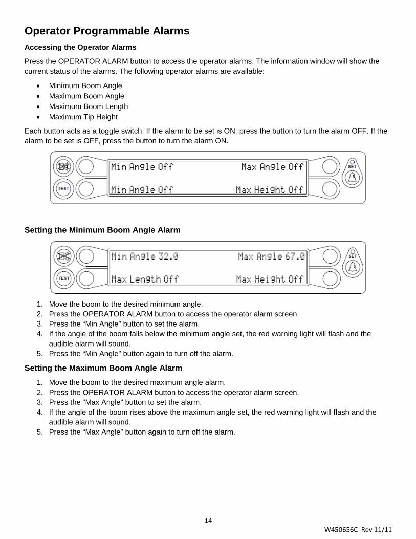
Operator Programmable Alarms Accessing the Operator Alarms Press the OPERATOR ALARM button to access the operator alarms. The information window will show the current status of the alarms. The following operator alarms are available:
• Minimum Boom Angle • Maximum Boom Angle • Maximum Boom Length • Maximum Tip Height
Each button acts as a toggle switch. If the alarm to be set is ON, press the button to turn the alarm OFF. If the alarm to be set is OFF, press the button to turn the alarm ON.
Setting the Minimum Boom Angle Alarm
1. Move the boom to the desired minimum angle. 2. Press the OPERATOR ALARM button to access the operator alarm screen. 3. Press the “Min Angle” button to set the alarm. 4. If the angle of the boom falls below the minimum angle set, the red warning light will flash and the
audible alarm will sound. 5. Press the “Min Angle” button again to turn off the alarm.
Setting the Maximum Boom Angle Alarm 1. Move the boom to the desired maximum angle alarm. 2. Press the OPERATOR ALARM button to access the operator alarm screen. 3. Press the “Max Angle” button to set the alarm. 4. If the angle of the boom rises above the maximum angle set, the red warning light will flash and the
audible alarm will sound. 5. Press the “Max Angle” button again to turn off the alarm.

15 W450656C Rev 11/11
Setting the Maximum Boom Length Alarm 1. Move the boom to the desired maximum length. 2. Press the OPERATOR ALARM button to access the operator alarm screen. 3. Press the “Max Length” button to set the alarm. 4. If the length of the boom exceeds the maximum length set, the red warning light will flash and the
audible alarm will sound. 5. Press the “Max Length” button again to turn off the alarm.
Setting the Maximum Tip Height Alarm 1. Move the boom to the desired maximum height. 2. Press the OPERATOR ALARM button to access the operator alarm screen. 3. Press the “Max Height” button to set the alarm. 4. If the height of the boom exceeds the maximum height set, the red warning light will flash and the
audible alarm will sound. 5. Press the “Max Height” button again to turn off the alarm.

16 W450656C Rev 11/11
Accessing the Swing and Work Area Alarms To access the swing and work area alarms from the main working screen, press the OPERATOR ALARM button twice.
On cranes where the swing sensor is housed in the swing drive the following screen will appear.
On cranes where the swing sensor is housed in a collector column, the preceding screen is skipped.
1. Press the “SET SWING AND/OR WORK AREA ALARMS?” button. 2. Press the “SET LEFT AND RIGHT SWING ALARMS?” button.
The swing alarms define a working arc and an exclusion zone based on two set points. The following diagram illustrates the working arc and exclusion zone.
• A left swing alarm is activated when swinging to the left. • A right swing alarm is activated when swinging to the right. • In this example, the working arc is the smaller piece of the
pie.
• A left swing alarm is activated when swinging to the left. • A right swing alarm is activated when swinging to the right. • In this example, the working arc is the larger piece of the
pie.
WARNING!
THE OPERATOR DEFINED SWING ALARM IS A WARNING DEVICE. ALL CRANE FUCNTIONS REMAIN OPERATIONAL WHEN ENTERING THE OPERATOR DEFINED EXCLUSION ZONE.
Setting the Left and Right Swing Alarms NOTE: In order for the swing alarms to function properly both alarms must be set. If the procedure is aborted prior to setting both points it will default to “OFF”.
17 W450656C Rev 11/11
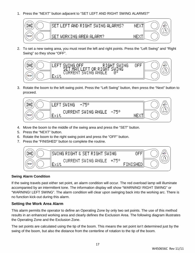
1. Press the “NEXT” button adjacent to “SET LEFT AND RIGHT SWING ALARMS?”
2. To set a new swing area, you must reset the left and right points. Press the “Left Swing” and “Right
Swing” so they show “OFF”.
3. Rotate the boom to the left swing point. Press the “Left Swing” button, then press the “Next” button to
proceed.
4. Move the boom to the middle of the swing area and press the “SET” button. 5. Press the “NEXT” button. 6. Rotate the boom to the right swing point and press the “OFF” button. 7. Press the “FINISHED” button to complete the routine.
Swing Alarm Condition If the swing travels past either set point, an alarm condition will occur. The red overload lamp will illuminate accompanied by an intermittent tone. The information display will show “WARNING! RIGHT SWING” or “WARNING! LEFT SWING”. The alarm condition will clear upon swinging back into the working arc. There is no function kick-out during this alarm.
Setting the Work Area Alarm This alarm permits the operator to define an Operating Zone by only two set points. The use of this method results in an enhanced working area and clearly defines the Exclusion Area. The following diagram illustrates the Operating Zone and the Exclusion Zone.
The set points are calculated using the tip of the boom. This means the set point isn’t determined just by the swing of the boom, but also the distance from the centerline of rotation to the tip of the boom.

18 W450656C Rev 11/11
WARNING! THE OPERATOR DEFINED WORK AREA ALARM IS A WARNING DEVICE. ALL FUNCTIONS REMAIN OPERATIONAL WHEN ENTERING THE OPERATOR DEFINED EXCLUSION ZONE. SAFE WORKING
DISTANCE IS THE TIME IT WOULD TAKE TO REACT TO AN ALARM AND FOR CRANE MOTION TO BE HALTED BEFORE ENCOUNTERING THE OBSTACLE. IT IS IMPORTANT TO SET POINTS THAT
ENSURE THE BOOM, ATTACHMENTS, HOOK LOAD, AND RIGGING, MAINTAIN A SAFE WORKING DISTANCE FROM THE OBSTACLE. AVOID POSITIONING THE BOOM, ATTACHMENT, LOAD, OR
RIGGING IN THE EXCLUSION ZONE WHEN MOVING TO SET POINTS 1 AND 2. ENSURE THE LOAD WILL MAINTAIN A SAFE DISTANCE FROM THE ARTICLE. IF THE CRANE OR OBSTACLE IS MOVED,
OR A DIFFERENT SIZED LOAD IS LIFTED, THE WORK AREA ALARM MUST BE RESET.
To access the swing and work area alarms from the main working screen press the OPERATOR ALARM button twice.
1. Press the “NEXT” button adjacent to “SET SWING AND/OR WORK AREA ALARMS?” 2. Press the “NEXT” button adjacent to “SET WORKING AREA ALARM?”
3. To set a new working area, you must reset the left and right points. Press the “Left Point” and “Right
Point” buttons so they show “OFF”.

19 W450656C Rev 11/11
4. Rotate the boom to the left point. This is the point to the left facing the exclusion zone to be defined. 5. Press the “LEFT POINT” button. The left point is now set. 6. Rotate the boom to right retracting the boom to move the load around the obstacle. Or, rotate the boom
to the left until the right point is reached. This is the point to the right facing the exclusion zone to be defined.
7. Press the “RIGHT POINT” button. The right point is now set.
To deactivate the swing alarms, follow steps 1-3 to reset the left and right points.
NOTE: In order for the work area alarm to function properly both alarms must be set. If the procedure is aborted prior to setting both points it will default to “OFF”.
Working Area Alarm Condition If the swing travels past either set point an alarm condition will occur. The red overload lamp will illuminate accompanied by an intermittent tone. The information window will display “!!EXCLUSION ZONE!!”. The alarm condition will clear upon swinging back into the operating zone. During a swing alarm condition, there is no function kick-out.
Zeroing the Swing Sensor To access the swing and work area alarms from the main working screen, press the OPERATOR ALARM button twice.
1. Press the “NEXT” button adjacent to “RESET SWING SENSOR ZERO?”
2. Ensure the boom is in its rest (stowed position) and press the “CONFIRM” button. 3. The swing is now zeroed.

20 W450656C Rev 11/11
Calibration The system contains a setup calibration mode that operates through the system display console. The setup mode provides a way to ensure the system sensors are set correctly following system installation or parts replacement.
This is a factory calibration sequence and assumes that installation of system components, cabling, and hydraulic connections have been successfully completed and checked.
It is important that each of this procedure is properly followed for the system to accurately provide load, rated capacity, warnings, and function kick-out.
WARNING! AT ALL TIMES, OBSERVE SAFE PRACTICES. ENSURE THE CRANE CAPACITY LIMITATIONS ARE
UNDERSTOOD AND THE CRANE CAPACITY PLATE IS FOLLOWED. DO NOT EXCEED MANUFACTURER’S SPECIFIED LIFTING LIMITATIONS.
Required Tools
• Phillips Screwdrivers • Digital Level – Accurate to 0.1° • Digital Voltmeter • Measuring tape (at least 100ft, preferably 200ft) – fiber-type in tenths of feet
Crane Configuration Before starting the system setup, position the crane on firm, level ground with the outriggers properly extended and set. It is recommended the crane be configured with no stowed or erected jib (bare boom) and reeved with a single part-of-line.
Fully retract the boom and set it to zero degrees (±0.1°) using a digital level.
Remove the reeling drum cover to expose the length and angle sensors.

21 W450656C Rev 11/11
Entering Calibration Mode The display will step through each setup operation, as required by the user. During setup, place the display console in a position that allows easy viewing while adjustments are being made within the reeling drum and operation of the display buttons.
To enter setup data, it is necessary to put the system in calibration mode. Once in calibration mode, you have five seconds to enter the security key sequence.
To enter calibration mode:
1. Press and hold the TEST and SET buttons simultaneously. The audible alarm will sound and you will be prompted to enter the security code.
2. Enter the security code in the order shown.
3. The computer will execute a brief self-test and enter calibration mode.
Number Entry
The display will change to the following when number entry is required.
Buttons B and D are used to scroll left and right. The “cursor” will appear as flashing <> brackets on either side of the number. Button A is used to enter the number. Button C is used to exit the number entry subroutine.
As each number is selected, press button A to enter it into the system. The number will then appear in the [ ] brackets. Up to five numbers may be entered. When entering a negative value, enter the numbers and decimal first, then enter the minus sign. If you enter a number incorrectly, select the < backspace and press the A button. When all the digits are correct, press the C button to calibrate the complete number.
EXAMPLE: To enter the value “2.98”:
1. Press button B or D until the number “2” is selected (indicated by the flashing <> brackets), then press button A to enter the number.
2. Select the decimal “.”, then press button A. 3. Repeat the previous steps to enter the number “9” and “8”. 4. If the value is correct, press button C to exit.

22 W450656C Rev 11/11
Extension Sensor Setup
Before these procedures are followed, ensure the reeling drum cable is layering correctly. Refer to Checking the Reeling Drum Cable Layering. This sensor is calibrated at the factory and should only be adjusted if it has been tampered with.
Extension Sensor Physical Zero
It is necessary to ensure the extension sensor potentiometer is correctly set to its minimum “zero” setting when the boom is fully retracted. This ensures the sensor will correctly measure over the full telescoping range of the boom.
1. Disengage the main gear wheel connected to the extension sensor by pulling the sensor arm in the direction shown.
2. Rotate the gear clockwise until the sensor clutch drags, or if equipped with a “ball detent” type clutch, clicks.
3. Rotate the gear counterclockwise about half a turn setting the voltage to 0.25 volts.
4. Carefully releasing the sensor arm, ensuring the voltage remains at 0.25 volts as the gears re-engage.
Extension Sensor Zero Calibration
1. Ensure boom is fully retracted. 2. Enter calibration mode. 3. Press the “Menu Up” or “Menu Down” until “02 Zero Sensors” appears in the information at the right. 4. Press the “02 Zero Sensors” to enter the routine.
5. Press the “Zero No. 2 = XX” to zero the extension sensor.
6. Press the “YES! Calibrate” to set the extension sensor to zero. 7. The retracted boom length should appear in the boom length window.
23 W450656C Rev 11/11
Angle Sensor Setup
The following procedures define how to reset and calibrate the angle sensor.
NOTE: This sensor is calibrated at the factory and should only be adjusted if it has been tampered with.
Angle Sensor Physical Zero
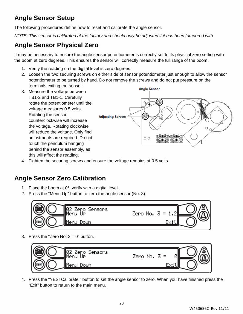
It may be necessary to ensure the angle sensor potentiometer is correctly set to its physical zero setting with the boom at zero degrees. This ensures the sensor will correctly measure the full range of the boom.
1. Verify the reading on the digital level is zero degrees. 2. Loosen the two securing screws on either side of sensor potentiometer just enough to allow the sensor
potentiometer to be turned by hand. Do not remove the screws and do not put pressure on the terminals exiting the sensor.
3. Measure the voltage between TB1-2 and TB1-1. Carefully rotate the potentiometer until the voltage measures 0.5 volts. Rotating the sensor counterclockwise will increase the voltage. Rotating clockwise will reduce the voltage. Only find adjustments are required. Do not touch the pendulum hanging behind the sensor assembly, as this will affect the reading.
4. Tighten the securing screws and ensure the voltage remains at 0.5 volts.
Angle Sensor Zero Calibration
1. Place the boom at 0°, verify with a digital level. 2. Press the “Menu Up” button to zero the angle sensor (No. 3).
3. Press the “Zero No. 3 = 0” button.
4. Press the “YES! Calibrate!” button to set the angle sensor to zero. When you have finished press the
“Exit” button to return to the main menu.

24 W450656C Rev 11/11
Spanning the Extension and Angle Sensors
Press the “Menu Up” or Menu Down” button until “03 Span Sensors” appears in the information window at the right.
WARNING!
SETTING SPANS ON THE CRANE WILL REQUIRE FULL EXTENSION OF THE BOOM. ENSURE THE CRANE IS SET UP ACCORDING TO THE MANUFACTURER’S OPERATION MANUAL TO ENSURE MAXIMUM STABILITY. ENSURE ALL BOOM EXTENSIONS AND LOADS ARE LIFTED WITHIN THE
APPROPRIATE LOAD CHARTS AND LIMITS. FAILURE TO COMPLY WITH MANUFACTURER’S LIMITS MAY RESULT IN SERIOUS INJURY OR DEATH.
Dimension “S” – This is the distance between the center of the boom pivot and the center of the sheave with the boom fully retracted.
Dimension “T” – This is the dimension between the center of the boom pivot and the center of the sheave with the boom fully extended.
The span of the boom is calculated by subtracting Dimension “S” from Dimension “T” (T – S = span).
Entering the Span
1. Raise the boom to approximately 65°, verify with a digital level. 2. Press the “Span No. 2 = X.X” button. 3. Press the “YES! Calibrate!” button to enter the span. To get the span, use the formula T – S = Span
from above.
4. Use the number entry procedure to enter the span.

25 W450656C Rev 11/11
5. Press the “Span No. 3 = X.X” button.
6. Press the “YES! Calibrate! Button to enter the angle. 7. Use the number entry procedure to enter the number shown on the digital level.
When you have finished, press the “Exit” button to return to the main menu.
Swing Sensor Setup
The swing sensor works by “counting” the gears on the swing drive. Based on the answers provided, the system will configured the proper application.
1. Press the “Menu Up” or “Menu Down” button until “04 Swing Sensor” appears in the information window at the right.
2. Press the “04 Swing Sensor” button to enter the routine. 3. Select the swing sensing method. Press the “Swing Drive” or “Collector Column” button. NOTE: If
“Collector Column” is selected, proceed to Zeroing the Sensor.
4. Press the “Yes” or “No” button to tell the system if a front bumper jack is installed. NOTE: If “Yes” is
selected, proceed to step 5. If “No” is selected, proceed to Zeroing the Sensor.
5. Select the type of swing the crane is equipped with. Press the “Continuous” (full 360° swing), or “Non-
Continuous” (limited clockwise and counterclockwise swing).
26 W450656C Rev 11/11
Zeroing the Swing Sensor To access the swing and work area alarms from the main working screen, press the OPERATOR ALARM button twice.
1. Press the “NEXT” button adjacent to “RESET SWING SENSOR ZERO?” 2. Ensure the boom is in its rest (stowed position) and press the “CONFIRM” button. 3. The swing is now zeroed.
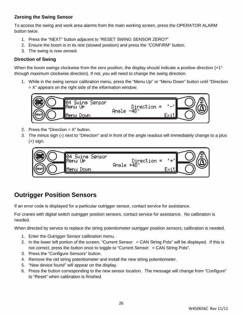
Direction of Swing
When the boom swings clockwise from the zero position, the display should indicate a positive direction (+1° through maximum clockwise direction). If not, you will need to change the swing direction.
1. While in the swing sensor calibration menu, press the “Menu Up” or “Menu Down” button until “Direction = X” appears on the right side of the information window.
2. Press the “Direction = X” button. 3. The minus sign (-) next to “Direction” and in front of the angle readout will immediately change to a plus
(+) sign.
Outrigger Position Sensors
If an error code is displayed for a particular outrigger sensor, contact service for assistance.
For cranes with digital switch outrigger position sensors, contact service for assistance. No calibration is needed.
When directed by service to replace the string potentiometer outrigger position sensors, calibration is needed.
1. Enter the Outrigger Sensor calibration menu. 2. In the lower left portion of the screen, “Current Sensor: = CAN String Pots” will be displayed. If this is
not correct, press the button once to toggle to “Current Sensor: = CAN String Pots”. 3. Press the “Configure Sensors” button. 4. Remove the old string potentiometer and install the new string potentiometer. 5. “New device found” will appear on the display. 6. Press the button corresponding to the new sensor location. The message will change from “Configure”
to “Reset” when calibration is finished.

27 W450656C Rev 11/11
MG
500
60-W
ay M
etri
Ree
ling
Dru
m
Wire
Har
ness
S
uppl
ied
by C
rane
M
anuf
actu
rer
Ree
ling
Dru
m
Con
ditio
ning
Sens
or
C
ondi
tioni
ng B
ox
BT
510
Dis
play
ATB
Sw
itch
Swin
g
Cha
in &
Wei
ght
Ass
embl
y
System Diagram – A450625 computer
A450656 computer similar, different connections on computer.
A450656 Connections

28 W450656C Rev 11/11
Troubleshooting This section is designed to aid in determining the location and type of problem experienced. It is important to follow the recommendations within this section before contacting a service professional.
System Self-Test
When the power is turned on or when the TEST button is pressed during operation, the computer and operator’s display console perform a self-test. This tests the computer, display console, cables, and sensors for problems.
During the self-test, all display functions (LEDs and text display) are activated, allowing the operator to check whether all indicators are functional. It is important the indications shown during the self-test are recognized and understood by the operator in order to aid in correctly determining computer and display communication problems.
For six seconds following “power on” or pressing the TEST button, the console will display:
All display segments of the percent of rated capacity meter will be black (ON).
All display of the load, angle, radius, length, and rated capacity windows will be black (ON), showing “188.8” or “888,800” for load and capacity.
All green confirguation indicators will be illuminated.
The red indicators for overload and ATB will be illuminated.
The yellow indicator for approaching overload will be illuminated.
The audible alarm will sound on the crane console.
The display will then show the crane model and chart number, the units of measurement, and the message: “SYSTEM SELF-TEST IN PROGRESS”.
After the self-test has completed, the brightness/contrast adjustment screen will appear for approximately one second followed by the normal working screen.
If any of the above processes do not occur, refer to Display Console Problems.
29 W450656C Rev 11/11
Error Codes
System Error Codes allow the operator to quickly locate and assess system problems.
Each time the system is turned, it goes through a self-test lasting approximately six seconds. This automatically detects most faults in the system.
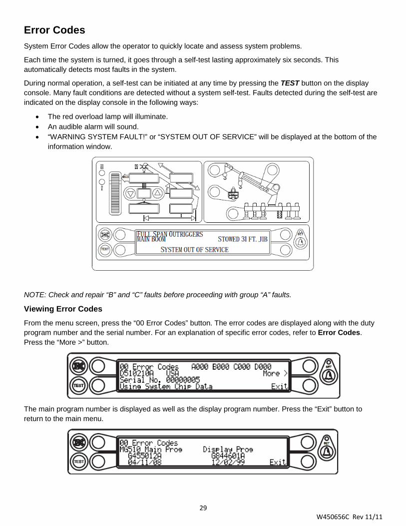
During normal operation, a self-test can be initiated at any time by pressing the TEST button on the display console. Many fault conditions are detected without a system self-test. Faults detected during the self-test are indicated on the display console in the following ways:
• The red overload lamp will illuminate. • An audible alarm will sound. • “WARNING SYSTEM FAULT!” or “SYSTEM OUT OF SERVICE” will be displayed at the bottom of the
information window.
NOTE: Check and repair “B” and “C” faults before proceeding with group “A” faults.
Viewing Error Codes From the menu screen, press the “00 Error Codes” button. The error codes are displayed along with the duty program number and the serial number. For an explanation of specific error codes, refer to Error Codes. Press the “More >” button.
The main program number is displayed as well as the display program number. Press the “Exit” button to return to the main menu.

30 W450656C Rev 11/11
Group “A” Error Codes – These codes represent faults for analog sensors.
Fault Code
Swing Sensor
Boom Angle
Sensor
Extension Sensor
Tdx 1 Rod
Pressure
Tdx 0 Piston
Pressure
Action (Refer to section in BOLD)
000 No Fault Found None 001 X
Replace computer. Replacing the Computer Unit. 002 X 003 X X 004 X Checking the Extension Sensor Voltage. 005 X X
Replace computer. Replacing the Computer Unit. 006 X X 007 X X X
008 X Checking the Angle Sensor Pendulum. Checking the Angle Sensor Drive Voltage. Checking the Angle Sensor Voltage.
009 X X Replace computer. Replacing the Computer Unit. 010 X X
011 X X X
012 X X Checking the Extension Sensor Drive Voltage. Checking the Extension Sensor Voltage.
013 X X X Replace computer. Replacing the Computer Unit. 014 X X X
015 X X X X 016 X WAD/ISS. 017 X X
Replace computer. Replacing the Computer Unit. 018 X X 019 X X X 020 X X Checking the Extension Sensor Drive Voltage. 021 X X X
Replace computer. Replacing the Computer Unit. 022 X X X 023 X X X X
024 X X Checking the Angle Sensor Drive Voltage. Checking the Angle Sensor Voltage. WAD/ISS.
025 X X X Replace computer. Replacing the Computer Unit. 026 X X X
027 X X X X
028 X X X
Checking the Extension Sensor Drive Voltage. Checking the Extension Sensor Voltage. Checking the Angle Sensor Drive Voltage. Checking the Angle Sensor Voltage. WAD/ISS.
029 X X X X Replace computer. Replacing the Computer Unit.
030 X X X X
031 X X X X X
Checking the Extension Sensor Drive Voltage. Checking the Extension Sensor Voltage. Checking the Angle Sensor Drive Voltage. Checking the Angle Sensor Voltage. WAD/ISS.
032 Or
higher
Internal Temperature Sensor Fault Replace computer. Replacing the Computer Unit.
31 W450656C Rev 11/11
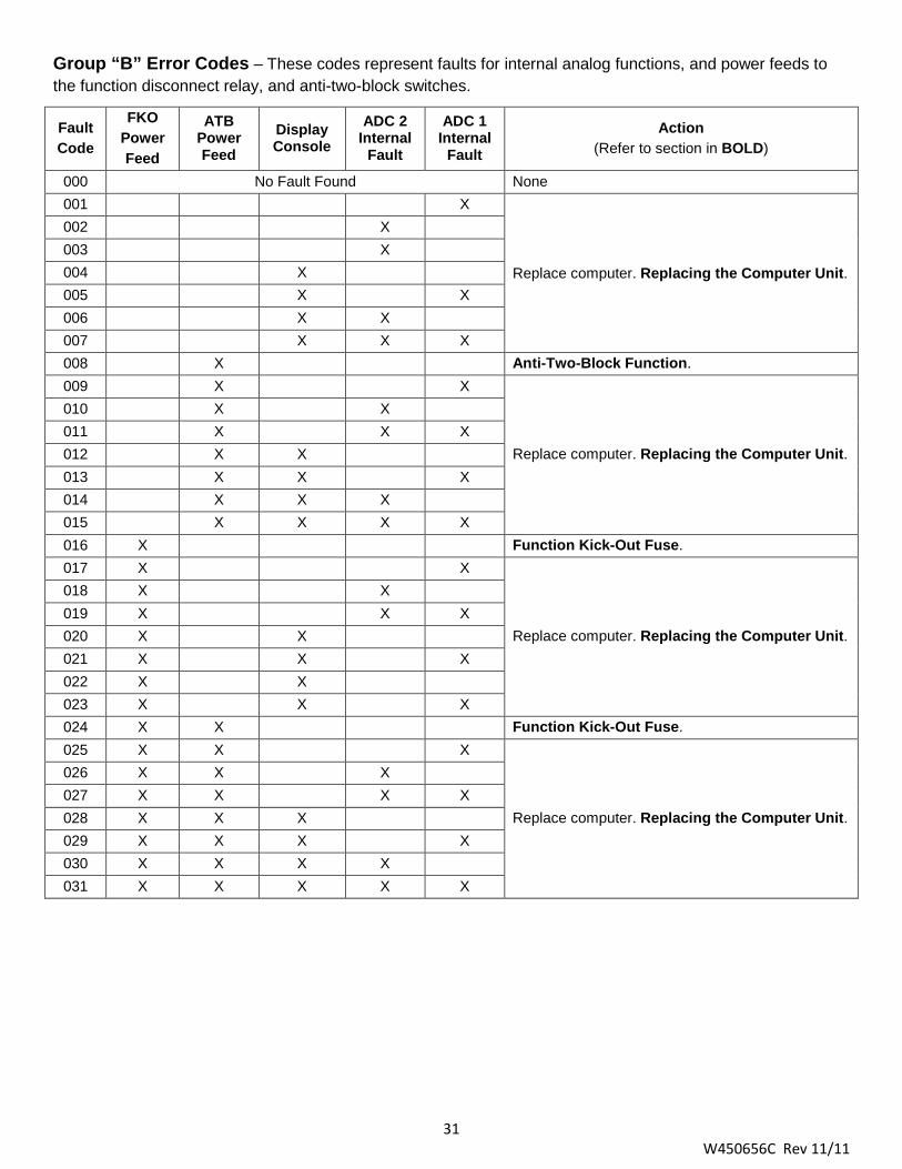
Group “B” Error Codes – These codes represent faults for internal analog functions, and power feeds to the function disconnect relay, and anti-two-block switches.
Fault Code
FKO Power Feed
ATB Power Feed
Display Console
ADC 2 Internal
Fault
ADC 1 Internal
Fault
Action (Refer to section in BOLD)
000 No Fault Found None 001 X
Replace computer. Replacing the Computer Unit.
002 X 003 X 004 X 005 X X 006 X X 007 X X X 008 X Anti-Two-Block Function. 009 X X
Replace computer. Replacing the Computer Unit.
010 X X 011 X X X 012 X X 013 X X X 014 X X X 015 X X X X 016 X Function Kick-Out Fuse. 017 X X
Replace computer. Replacing the Computer Unit.
018 X X 019 X X X 020 X X 021 X X X 022 X X 023 X X X 024 X X Function Kick-Out Fuse. 025 X X X
Replace computer. Replacing the Computer Unit.
026 X X X 027 X X X X 028 X X X 029 X X X X 030 X X X X 031 X X X X X
32 W450656C Rev 11/11
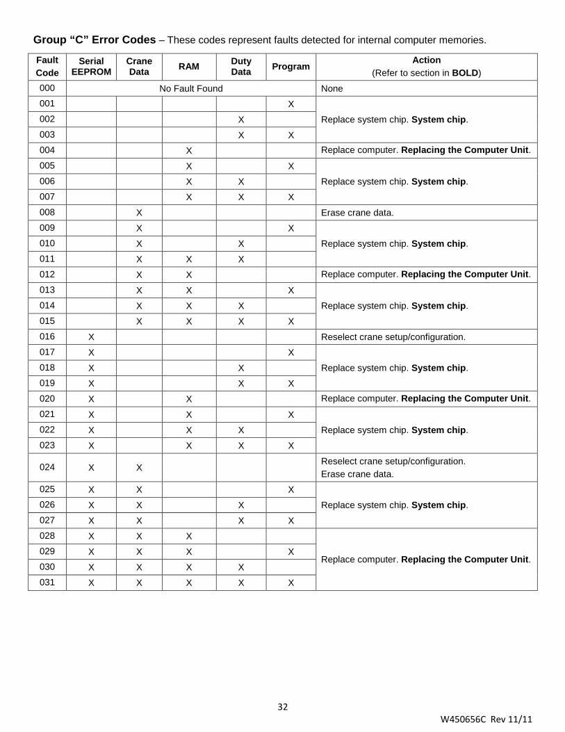
Group “C” Error Codes – These codes represent faults detected for internal computer memories.
Fault Code
Serial EEPROM
Crane Data RAM Duty
Data Program Action
(Refer to section in BOLD) 000 No Fault Found None 001 X
Replace system chip. System chip. 002 X 003 X X 004 X Replace computer. Replacing the Computer Unit. 005 X X
Replace system chip. System chip. 006 X X 007 X X X 008 X Erase crane data. 009 X X
Replace system chip. System chip. 010 X X 011 X X X 012 X X Replace computer. Replacing the Computer Unit. 013 X X X
Replace system chip. System chip. 014 X X X 015 X X X X 016 X Reselect crane setup/configuration. 017 X X
Replace system chip. System chip. 018 X X 019 X X X 020 X X Replace computer. Replacing the Computer Unit. 021 X X X
Replace system chip. System chip. 022 X X X 023 X X X X
024 X X Reselect crane setup/configuration. Erase crane data.
025 X X X
Replace system chip. System chip. 026 X X X 027 X X X X 028 X X X
Replace computer. Replacing the Computer Unit. 029 X X X X 030 X X X X 031 X X X X X
33 W450656C Rev 11/11
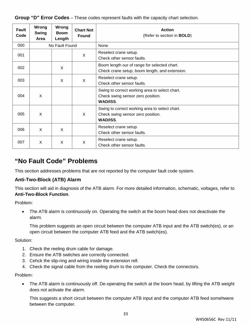
Group “D” Error Codes – These codes represent faults with the capacity chart selection.
Fault Code
Wrong Swing Area
Wrong Boom Length
Chart Not Found
Action (Refer to section in BOLD)
000 No Fault Found None
001 X Reselect crane setup. Check other sensor faults.
002 X Boom length our of range for selected chart. Check crane setup, boom length, and extension.
003 X X Reselect crane setup. Check other sensor faults.
004 X Swing to correct working area to select chart. Check swing sensor zero position. WAD/ISS.
005 X X Swing to correct working area to select chart. Check swing sensor zero position. WAD/ISS.
006 X X Reselect crane setup. Check other sensor faults.
007 X X X Reselect crane setup. Check other sensor faults.
“No Fault Code” Problems
This section addresses problems that are not reported by the computer fault code system.
Anti-Two-Block (ATB) Alarm This section will aid in diagnosis of the ATB alarm. For more detailed information, schematic, voltages, refer to Anti-Two-Block Function.
Problem:
• The ATB alarm is continuously on. Operating the switch at the boom head does not deactivate the alarm.
This problem suggests an open circuit between the computer ATB input and the ATB switch(es), or an open circuit between the computer ATB feed and the ATB switch(es).
Solution:
1. Check the reeling drum cable for damage. 2. Ensure the ATB switches are correctly connected. 3. Cehck the slip-ring and wiring inside the extension rell. 4. Check the signal cable from the reeling drum to the computer. Check the connectors.
Problem:
• The ATB alarm is continuously off. De-operating the switch at the boom head, by lifting the ATB weight does not activate the alarm.
This suggests a short circuit between the computer ATB input and the computer ATB feed somehwere between the computer.

34 W450656C Rev 11/11
Solution:
1. Check the reeling drum cable for damage. 2. Ensure the ATB switches are correctly connected. 3. Cehck the slip-ring and wiring inside the extension rell. 4. Check the signal cable from the reeling drum to the computer. Check the connectors.
Displayed Load or Radius Errors
This section will aid in diagnosis of load and radius errors. Load or radius errors may cause early or late tripping of the overload alarms. Accuracy of load, radius, length, and angle is determined by the correct installation and maintenance of the system sensors.
Accuracy of load is governed by the radius accuracy, and the extension, angle, pressure sensors.
Accuracy of radius (unloaded) is governed by the extenion and angle sensors. Ensure there are no system faults before continuing.
Checking the Boom Extension
1. Ensure the boom is fully retracted. 2. Ensure the reeling drum cable is correctly layered. Any stacking of the cable will cause extension errors
when the boom is fully retracted, causing the system to exceed the 0.5ft tolerance allowed by the computer. If the reeling drum cable is stacking on the reel, refer to Checking the Reeling Drum Cable Layering.
3. Check the zero of the extension sensor with the boom fully retracted. If the value is incorrect, refer to Extension Sensor Setup.
4. Fully extend the boom and ensure the boom length value matches the maximum length of the boom. If the value is incorrect, refer to Extension Sensor Span Calibration.
Checking the Main Boom Radius
1. Fully retract the boom and ensure the crane is correctly configured. 2. Raise the boom to 45° and measure the radius. The measured radius must match the displayed radius
within ±0.2ft. If it does not match, refer to Check Boom Angle. If it does match, refer to Checking Pressure Sensors.
NOTE: The required accuracy of the measured radius is 0.1ft. Always use a quality tape that does not stretch and is graduated in tenths of a goot. Measure between the swing center of the crane and the hook line, use a single part-of-line, and center the crane over the front for rough-terrain cranes, or over the rear for truck cranes.
Checking the Boom Angle
1. Fully retract the boom. 2. Set the boom to 0° and verify with an inclinometer or digital level. If the displayed value is not 0.0°, refer
to Checking the Angle Sensor Pendulum, Angle Sensor Physical Zero, and Angle Sensor Zero Calibration.
NOTE: The required accuracy of measured angles is 0.2°. Always use a quality inclinomoter or digital level.
3. Boom up to a high angle, approximately 70° and measure. Ensure the display angle matches the inclinometer or digital level reading within 0.2°. If the displayed angle is incorrect, refer to Spanning the Extension and Angle Sensors.

35 W450656C Rev 11/11
Checking the Pressure Sensors
The pressure sensors are calibrated at the factory and may not be individually replaced. Any serious problem will require replacement of the entire computer unit.
1. Lower the boom until the boom hoist cylinder is fully retracted and on its stop. 2. Loosen both hydraulic connections to the pressure sensors to ensure zero pressure is present on the
sensors. 3. Enter calibration mode and got to Menu “16 Data Retrieval” to view both sensor pressure and nett
pressure. 4. Check the pressure values of both sensors. They should be between -75 and +75 psi. If not, replace
the computer unit. 5. Check the nett pressure. This should be between -35 and +35 psi. If not, replace the computer unit.

36 W450656C Rev 11/11
Computer Unit The computer unit reads the sensors, controls computations and disconnect functions, and communicates with the display console/internal bar graph.
The A450625 computer unit directly connects to the crane wiring harness via 60-way bulkhead connector. There are no wiring connections or screw terminals within the unit. Contained within the unit are the hydraulic pressure sensors. These sensors are calibrated at the factory and may not be replaced separately in the field.
A450625 Computer Unit
A450656 Computer Unit
37 W450656C Rev 11/11
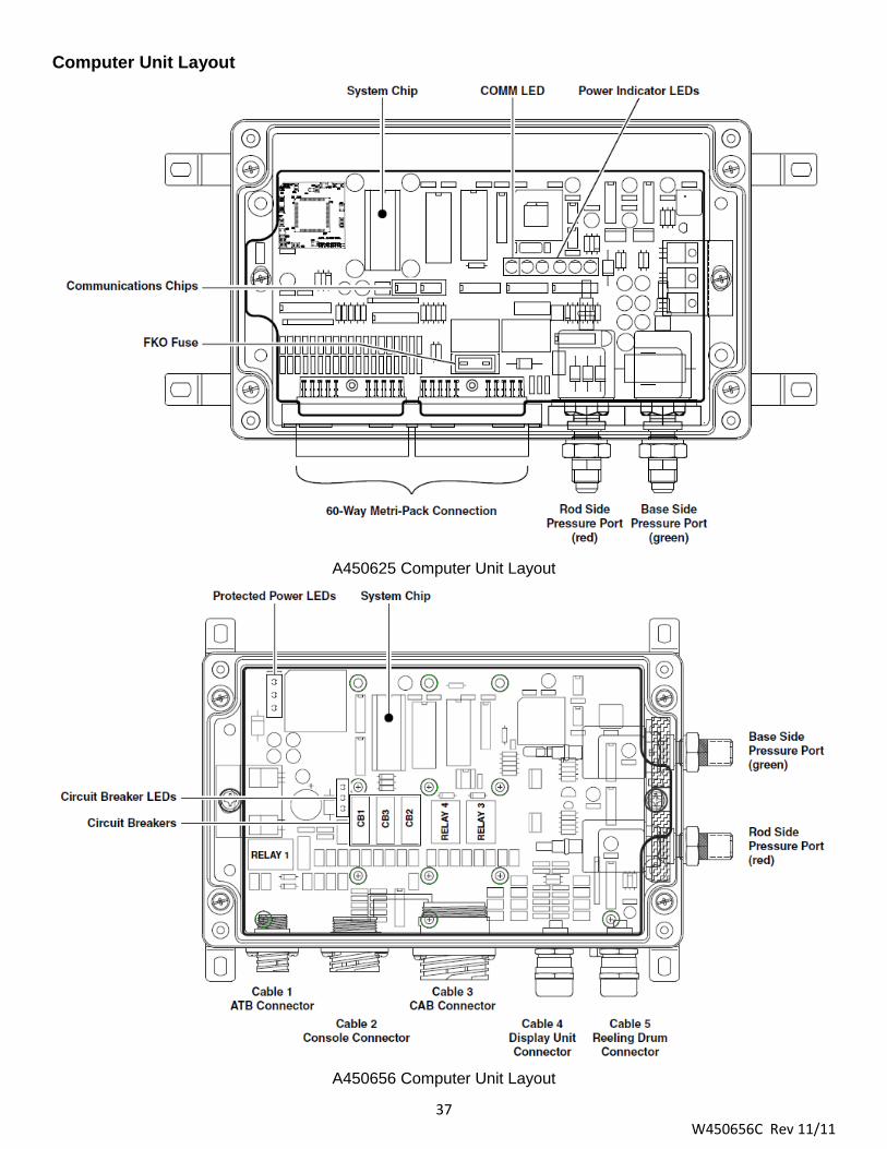
Computer Unit Layout
A450625 Computer Unit Layout
A450656 Computer Unit Layout

38 W450656C Rev 11/11
Internal Status Indicators Each computer unit contains six green, LED indicators to aid in diagnosing power supply and communications operation within the system. Remove the lid of the computer and check these indicators.
The A450625 computer has five power indicators and one communication indicator (COMM). With the exception of the COMM indicator, all indicators should be illuminated at the same brightness level with the system power on. The A450656 computer has three protected power indicators and three indicators for removable circuit breakers.
A missing or dimly lit indicator points to a power supply problem. Check the indicator chart for repair actions.
A450625 Computer Indicator States (black = off) Action
No power to computer. • Check crane power and circuit breaker.
+VP power to display console shorted to crane ground. • Check display console cable
+10V relay power interal short or regulator failure. • Replace computer. Refer to Replacing the computer Unit.
+5VD digital power internal short or regulator failure. • Replace computer. Refer to Replacing the computer Unit.
+5VA analog power/drive to sensors. • Check extension reel connection inside reel and wiring to
extension reel.
39 W450656C Rev 11/11
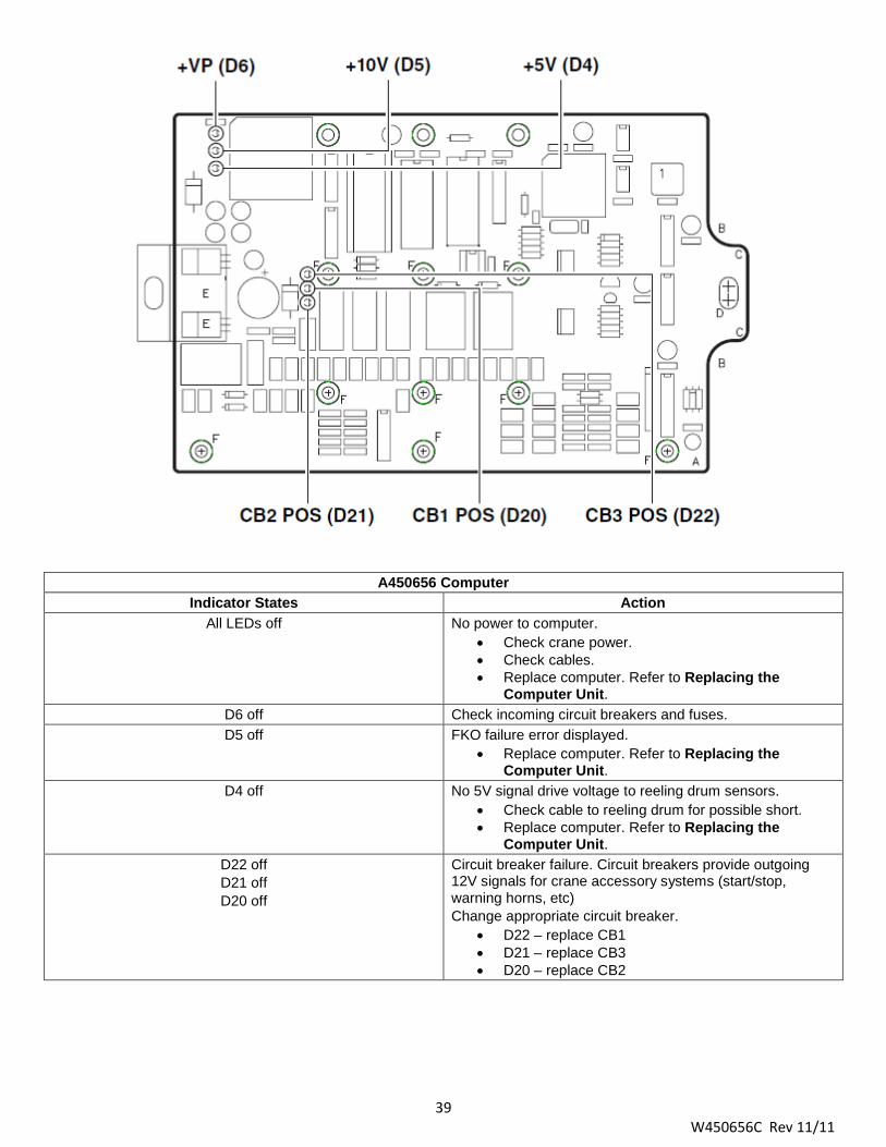
A450656 Computer Indicator States Action
All LEDs off No power to computer. • Check crane power. • Check cables. • Replace computer. Refer to Replacing the
Computer Unit. D6 off Check incoming circuit breakers and fuses. D5 off FKO failure error displayed.
• Replace computer. Refer to Replacing the Computer Unit.
D4 off No 5V signal drive voltage to reeling drum sensors. • Check cable to reeling drum for possible short. • Replace computer. Refer to Replacing the
Computer Unit. D22 off D21 off D20 off
Circuit breaker failure. Circuit breakers provide outgoing 12V signals for crane accessory systems (start/stop, warning horns, etc) Change appropriate circuit breaker.
• D22 – replace CB1 • D21 – replace CB3 • D20 – replace CB2

40 W450656C Rev 11/11
The COMM Indicator (A450625 Computer only) The communications LED (COMM indicator) provides an indication of the communication with the display console and the running state of the computer program.
Carefully observe the COMM indicator and the display console at power on and through the self-test. Use the following chart in troubleshooting.
COMM Indicator Indications at Power On Action From power on, the COMM indicator does not illuminate. During and after the self-test period of eight seconds, the COMM indicator remains off.
The computer is not running. Check status indicators. Refer to Internal Status Indicators. Try to reset the system by powering off and on again. Listen to the computer for the relays to click. If they do not click, replace the system chip. If not successful, replace the computer. If the relays do click, replace communication chips IC1 and IC2. Refer to Communications Chips. A450625 only.
From power on, the COMM indicator flashes at a fast rate and never stops. The display console never goes to normal and displays “l88.8” or “888,800” in the number display windows.
Communication with the display has not been made. Check connector at rear of the display console.
From power on, the COMM indicator flashes briefly, then switches off. After a few seconds, the COMM indicator starts to flash at a fast rate and never stops.
This is the normal operation of the communication between the computer and display console. If there are any problems with the indications on the display console, refer to Display Console Problems.
Replacing the Computer Unit It is recommended to replace the system chip when changing the computer unit. This ensures the lastest version of the chip is installed and eradicates problems that may have been caused by the existing chip.
Computer Removal
1. Retract the boom completely and place it in the rest (stowed position). 2. Turn off power to the crane. 3. Disconnect the hydrualic and electrical connections to the computer unit. 4. Remove the hardware securing the computer to the cab wall and remove the computer.
Computer Installation
1. Ensure the correct system chip is installed in the computer. Refer to System Chip. 2. Secure the computer unit to the cab wall. Ensure all electrical connections face downward. 3. Remove the protective covers from the electrical connectors and connect the cables to their respective
positions on the computer. 4. Remove the protective caps from the hydraulic ports and connect the hydraulic hoses.
Power Up and Calibration
Switch the crane power on and ensure all the LED check lights within the computer unit are illuminated. Ensure the COMM LED is flashing and the display console is operating. Refer to Calibration.

41 W450656C Rev 11/11
Computer Unit Replaceable Parts
• The system chip (IC16). • Communications chip (IC1 and IC2) that communicate with the display console and are pluggable
(A450625 only). • A standard 10-amp automotive fuse, protecting the power feed to the function disconnect relay
(A450625 only). • Circuit breakers (A450656 only).
System Chip (IC16)
The system chip contains program data, capacity charts, and calibration data for the crane. This chip must match the load chart in the crane. Installation of system chip does not necessitate recalibration of the system.
Remove the Existing Chips (Applies to System chip and Communications Chips)
WARNING! THE COMPUTER IS AN ESD SENSITIVE DEVICE. YOU MUST MAINTAIN A STATIC SAFE WORK
ENVIRONMENT. USE A FIELD SERVICE GROUNDING KIT OR OTHER STATIC DISSIPATIVE PRODUCT WHILE HANDLING THE COMPUTER AND/OR COMPONENTS.
1. Remove electrical power to the computer. 2. Using a #3 Phillips screwdriver, loosen the four screws at the corners of the computer box. Remove the
lid, place carefully to avoid damaging the seal. 3. Locate the chip to be replaced. 4. Position the chip removal tool onto the chip to be replaced.
WARNING!
DO NOT USE A SCREWDRIVER, KNIFE, OR OTHER TOOL TO REMOVE THE COMPUTER CHIPS. DOING SO WILL DAMAGE THE CHIPS AND/OR THE COMPUTER CIRCUIT BOARD AND WILL VOID
ANY WARRANTY.
5. Grasp the trigger handles and pull upward. 6. The chip removal tool will automatically secure and remove the chip in one motion.

42 W450656C Rev 11/11
Installing the Replacement System Chip
1. Ensure the pins of the replacement chip are aligned properly. If any pins are bent, carefully realign them.
2. Ensure the chip is oriented correctly. The indentation on the chip should match up to the indentation on the socket.
3. Place the chip into the socket, do not apply pressure at this time. Ensure all the pins of the chip are aligned with the respective holes in the socket.
4. Using a finger from each hand, apply equal pressure to both ends of the system chip to fully seat it into the socket.
5. Reinstall the cover and tighten the screws. 6. Reconnect the computer to the electrical
supply.
Communications Chips (A450625 Only) The communications chips, IC1 and IC2, provide communication between the computer unit and the display console. These chips are replaceable. Replacement of the communications chip does not necessitate recalibration of the system.
Function Kick-out Fuse (A450625 only)
The computer unit contains a replaceable fuse that protects the function kick-out circuit if a short circuit across the crane kick-out solenoid occurs.
Replace the fuse, FS2 on the computer board, if system error codes indicate the function kick-out power feed is missing. Establish the crane circuit breaker is closed and power from the crane is present.
Before replacing the fuse, ensure any electrical shorts that may have caused the failure of the original fuse have been removed.
Circuit Breaker Protection (A450656 only) Main power to the computer is handled with three self-resetting circuit breakers. The circuit breakers work when a short causes the power to go to ground and heats up the circuit breaker. Once the circuit breaker has cooled down, it will reset and continue normal operation. If a function loss becomes intermittent, any of the power wires to the console or the FKO could be shorting. CB1 and CB2 are for console options. CB3 is for the FKO circuit.
Replacing the Circuit Breaker
The circuit breaker can be replaced in the field with one of the same type. Contact the manufacturer or your service representative for a replacement. Do not use any other material, even temporarily, as a replacement. Do not use any other material as a replacement.
To remove the circuit breaker; grasp firmly and pull it from the computer board. It may be necessary to slightly rock and forth to loosen.
Remove any excess tabs on the replacement circuit breaker as shown in the illustration. The blades on the circuit breaker are offset, but can be installed in either direction. Ensure the circuit breaker is aligned with the outline on the computer board.

43 W450656C Rev 11/11
Computer Wiring Harnesses
Computer Wiring Harnesses – A450625 Computer
The A450625 computer uses a 60-way Metri Pack connector for interface between the computer and components. There is no internal wiring. Refer to the crane manufactuer for faults associated with the harness.
Computer Wiring Harnesses – A450656 Computer Any faults with the ATB, Console, or CAB connectors should be referred to the crane manufacturer.
Display Unit Connector
Wire / Terminal Number Color / Blade Function 1 / 1 Black/BLD33 Display Power 2 / 3 Black/BLD30 Display Data “A” 3 / 4 Black/BLD31 Display Data “B” 4 / 6 Black/BLD32 Display Reset N/A Yellow/Green/BLD34 Display Ground
Reeling Drum Connector
Terminal Number Color / Blade Function A Black/BLD24 ATB Limit Switch Power B White/BLD25 Boom Extension Signal C Green/BLD26 Boom Angle Signal D Orange/BLD27 ATB Limit Switch Signal E Red/BLD28 Boom Sensor Power F Blue/BLD29 Boom Sensor Ground

44 W450656C Rev 11/11
Pressure Sensors
The two pressure sensors are mounted within the computer unit. One is connected to the piston side of the boom hoist cylinder with a flexible hose; the other is connected to the rod side of the boom hoist cylinder with a flexible hose. Both hoses are protected by velocity fuses. These are mounted in the boom hoist cylinder valve block at the end of cylinder.
The the piston side sensor is subject to the hydraulic pressure necessary to support the weight of the boom, any attachments, and the load. The rod side sensor monitors the pressure necessary to control the down motion of the boom. The computer uses this information (along with the extension, length, and angle sensors) to compute the weight of the suspended load. The maximum continuous working pressure for these devices is 250 bar (3625 psi). The pressure sensors are not field replaceable.
Checking Pressure Sensors
The pressure sensors are calibrated at the factory and may not be individually replaced. Any serious problem will require replacement of the entire computer unit.
1. Lower the boom until the boom hoist cylinder is fully retracted and on its stop. 2. Loosen both hydraulic connections to the pressure sensors to ensure zero pressure is present on the
sensors. 3. Enter calibration mode and got to Menu “16 Data Retrieval” to view both sensor pressure and nett
pressure. 4. Check the pressure values of both sensors. They should be between -75 and +75 psi. If not, replace
the computer unit. 5. Check the nett pressure. This should be between -35 and +35 psi. If not, replace the computer unit.

45 W450656C Rev 11/11
Display Console The operator’s display console allows the user to see the crane values (angle, radius, load, etc) and crane configuration selection. The display also provides calibration functions use for testing and fault diagnosis.
Display Console Problems
Failure of either the display or the computer unit, or the cable connecting the two, can cause display console problems. “No Fault” diagnoses of other systems can be performed when the display console is showing a malfunction.
To solve display conolse indications, observe the display console at “power on” and through the self-test.
Problem Action (refer to section in Bold)
There are no display console indications at all when the power is turned on. All displays remain black and no lights are illuminated.
Internal Status Indicators.
The load, angle, radius, length, and rated capacity display windows do not show “l88.8” or the bar graph display window has missing black segments during the self-test.
Replacing the Display Console.
The red or yellow indicator lights do not illuminate during self-test. Replacing the Display Console.
The display console does not do the self-test. No words or logical numbers ever appear after power on. The displays look jumbled with missing segments.
Replacing the Display Console.
The display console lights are illuminated. Load, angle, radius, length, and rated capacity show “l88.8” or “888,800” for load and capacity, but the display window shows only a message: “Bad communications with main computer”.
• Display console is OK. • Check connectors on the rear of the display
console. • The COMM indicator.
46 W450656C Rev 11/11
Checking the Display Console
The display may become damaged when operated for extended periods under extreme conditions. The damage is not always apparent. To help identify subtle faults that may be attributed or mistaken for other problems, review the following.
Reading the Liquid Crystal Displays
Always adjust the display contrast first. On bracket-mounted models, reposition the console. The most common problem is reflections on the screen.
NOTE: It may not be possible to correct this completely, on display consoles exposed to bright sunlight. If the problem concerns the contents of one or more of the display screens, refer to Troubleshooting.
Unresponsive Buttons
All buttons are not available for use at all times. Ensure the non-responsive button is programmed to respond at this point in the operation of the system. Press the button in the center. Pressing the printed symbol off-center may not activate the switch underneath. Damaged or worn buttons may not properly activate the switch. In case of damaged or worn buttons, refer to Replacing the Display Console.
Connectors
A single circular connector is positioned on the rear of the display console. This connector carries power and signals from the computer unit. Examine this connector carefully. It is possible for the pins and sockets to bend, break, or ‘be pushed back’ inside the housing.
Moisture
The display console offers limited protection against dust and water, when installed correctly. If the display console has been exposed to severe weather conditions or humidity, some moisture may seep in. If this occurs, it may be necessary to replace the display unit. Do not attempt to open the housing of the display unit to dry it out.
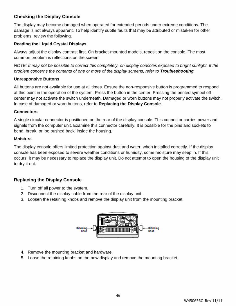
Replacing the Display Console 1. Turn off all power to the system. 2. Disconnect the display cable from the rear of the display unit. 3. Loosen the retaining knobs and remove the display unit from the mounting bracket.
4. Remove the mounting bracket and hardware. 5. Loose the retaining knobs on the new display and remove the mounting bracket.

47 W450656C Rev 11/11
6. Use the supplied hardware to install the new mounting bracket onto the dash.
7. Install the new display onto the mounting bracket and tighten the retaining knobs. 8. Connect the display cable at the rear of the new display.

48 W450656C Rev 11/11
Extension Reel The primary operation of the extenion reel is to measure the extension of the telescoping sections of the main boom. The extension reel also includes the ange senor, and an electrical slip-ring which transfers the ATB signal from the reeling drum cable to the system computer.
It is importat the setup and maintenance is done correctly. Incorrect installation or maintenance will result in system calculation errors.
Reeling Drum Cutaway Diagram

49 W450656C Rev 11/11
Checking the Reeling Drum Cable Layering
The reeling drum is designed to provide accurate measurement of boom extension when the reeling drum cable forms a single, flat layer across the surface of the extension reel as the boom is extended and retracted. Any stacking of the cable will cause extension errors as the boom retracts.
1. Extend the boom fully and retract the boom fully. 2. Ensure the reeling drum cable forms a single, flay layer across the surface of the reeling drum, with
each turn laying next to the last. 3. If any stacking or buildup of the cable occurs, ensure the first cable guide at the top of the boom root
section is correctly aligned with outside edge of the reeling drum. 4. Clean the reeling drum cable, then lubricate with a silicone spray.

50 W450656C Rev 11/11
Extension Sensor
Extension Sensor Physical Zero
It is necessary to ensure the extension sensor potentiometer is correctly set to “zero” when the boom is fully retracted. This ensures the sensor will correctly measure the full range of the boom.
1. Disengage the main gear wheel connected to the extension sensor by pulling the sensor arm in the direction shown.
2. Rotate the gear clockwise until the sensor clutch drags or, if equipped with a ball-detent type clutch,
clicks. 3. Rotate the sensor counterclockwise a ½ turn and release the sensor arm to re-engage the gears on the
sensor arm. 4. Rotate the gear counterclockwise about a ½ turn setting the voltage at 0.2 volts. Carefully release the
sensor arm, ensuring the voltage remains at 0.2 volts as the gears re-engage.
Extension Sensor Zero Calibration
The computer must identify where the zero point of the extension sensor has been set. It is necessary to calibrate the zero setting of the potentiometer. Ensure the mechanical zero has been properly set as described previously.
Before exiting the calibration routine, ensure the displayed value is between -4 and +4.
Extension Sensor Span Calibration
The computer must be able to treat measurements of the distance provided by the extension sensor. It is necessary to calibrate the span of the extension potentiometer. Ensure the calibration zero has been properly set as describe previously.
Checking the Extension Sensor Drive Voltage
1. Remove the reeling drum cover. 2. Use a digital voltmeter to measure the voltage between TB1-4 and TB1-1 wires at the terminal block. 3. Ensure the voltage is between 4.7 and 5.3 volts.
Voltages outside this range indicates a connection problem between the reeling drum and the computer, or a short circuit within the extension reel.
51 W450656C Rev 11/11
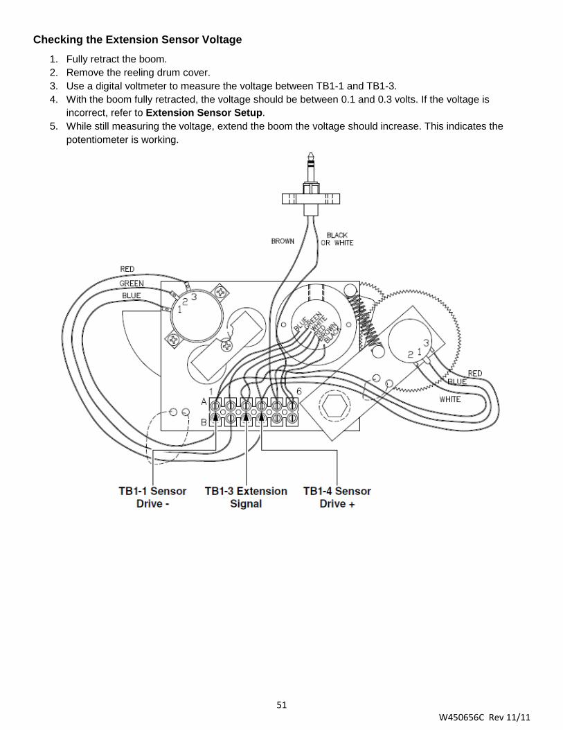
Checking the Extension Sensor Voltage
1. Fully retract the boom. 2. Remove the reeling drum cover. 3. Use a digital voltmeter to measure the voltage between TB1-1 and TB1-3. 4. With the boom fully retracted, the voltage should be between 0.1 and 0.3 volts. If the voltage is
incorrect, refer to Extension Sensor Setup. 5. While still measuring the voltage, extend the boom the voltage should increase. This indicates the
potentiometer is working.

52 W450656C Rev 11/11
Angle Sensor Angle Sensor Physical Zero
It may be necessary to ensure the angle sensor potentiometer is correctly set to its physical zero setting with the boom at 0°. This ensures the sensor will correctly measure the full angle range of the boom.
1. Verify the 0° reading with an inclinometer or digital level. 2. Loosen the two securing screws on either side of the potentiometer just enough to allow the sensor to
be turned by hand. Do not remove the screws and do not put pressure on the terminals exiting the sensor.
3. Use a digital voltmeter to measure the voltage between TB1-2 and TB1-1, rotate the potentiometer until
the voltage measure 0.4 volts. Rotating the sensor counterclockwise will increase the voltage. Rotating clockwise will reduce the voltage. Only fine adjustments are required. Do not touch the pendulum hanging behind the sensor assembly, as this will affect the reading.
4. Tighten the adjusting screws and ensure the voltage remain at 0.4 volts.
Angle Sensor Zero Calibration
The computer must be able to identify where the zero point of the angle sensor has been set. It is necessary to calibrate the zero setting of the potentiometer. Before calibration, ensure the physical zero has been properly set.
For detailed instructions, refer to Angle Sensor Setup.
Before exiting the calibration routine, ensure the display value is between -4 and +4.
Angle Sensor Span Calibration
The computer must be able to identify where the zero point of the angle sensor has been set. It is necessary to calibrate the span of the angle potentiometer. Before continuing, ensure the calibration zero has been properly set.
For detailed instructions, refer to Spanning the Extension and Angle Sensors.
Before exiting the calibration routine, ensure the displayed value is between -0.1° and +0.1° of the value entered.

53 W450656C Rev 11/11
Checking the Angle Sensor Pendulum The angle sensor uses a copper pendulum, mounted behind the sensor assembly. It is dampened with magnets to prevent uncontrolled swinging during boom movements.
If problems with the angle sensor are suspected, ensure the pendulum and potentiometer are operating without restriction, before checking electrical operation and performing any calibration.
1. Remove the reeling drum cover. 2. Locate the pendulum. 3. Push the pendulum downwards in the direction and ensure it isn’t sticking. Some resistance of
movement may be encountered as the pendulum is moved, this is caused by damping of the magnets.
4. Release the pendulum and ensure that it returns with free, but controlled movement back to its original
position. 5. Push the pendulum downwards a few more times, ensuring it returns properly.
NOTE: If any sticking of the pendulum is encountered while performing the above checks, ensure there are no wires touching the pendulum or other obvious problems. If not, it will be necessary to replace the sensor assembly.
Checking the Angle Sensor Drive Voltage
1. Remove the reeling drum cover. 2. Use a digital voltmeter to measure the voltage between TB1-4 and TB1-1 wires at the terminal block
mounted on the sensor baseplate assembly. 3. Ensure the voltage is between 4.7 and 5.3 volts.
Voltages outside the range indicate a connection problem between the extension reel and the computer, or a short circuit within the reeling drum. Check the reeling drum wiring within the reel and at the boom foot base connector.
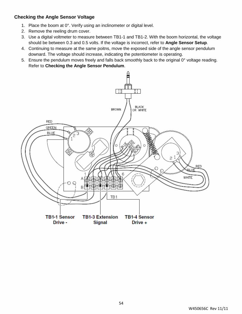
54 W450656C Rev 11/11
Checking the Angle Sensor Voltage
1. Place the boom at 0°. Verify using an inclinometer or digital level. 2. Remove the reeling drum cover. 3. Use a digital voltmeter to measure between TB1-1 and TB1-2. With the boom horizontal, the voltage
should be between 0.3 and 0.5 volts. If the voltage is incorrect, refer to Angle Sensor Setup. 4. Continuing to measure at the same poitns, move the exposed side of the angle sensor pendulum
downard. The voltage should increase, indicating the potentiometer is operating. 5. Ensure the pendulum moves freely and falls back smoothly back to the original 0° voltage reading.
Refer to Checking the Angle Sensor Pendulum.
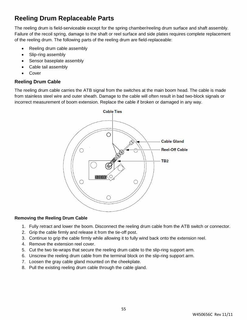
55 W450656C Rev 11/11
Reeling Drum Replaceable Parts
The reeling drum is field-serviceable except for the spring chamber/reeling drum surface and shaft assembly. Failure of the recoil spring, damage to the shaft or reel surface and side plates requires complete replacement of the reeling drum. The following parts of the reeling drum are field-replaceable:
• Reeling drum cable assembly • Slip-ring assembly • Sensor baseplate assembly • Cable tail assembly • Cover
Reeling Drum Cable
The reeling drum cable carries the ATB signal from the switches at the main boom head. The cable is made from stainless steel wire and outer sheath. Damage to the cable will often result in bad two-block signals or incorrect measurement of boom extension. Replace the cable if broken or damaged in any way.
Removing the Reeling Drum Cable
1. Fully retract and lower the boom. Disconnect the reeling drum cable from the ATB switch or connector. 2. Grip the cable firmly and release it from the tie-off post. 3. Continue to grip the cable firmly while allowing it to fully wind back onto the extension reel. 4. Remove the extension reel cover. 5. Cut the two tie-wraps that secure the reeling drum cable to the slip-ring support arm. 6. Unscrew the reeling drum cable from the terminal block on the slip-ring support arm. 7. Loosen the gray cable gland mounted on the cheekplate. 8. Pull the existing reeling drum cable through the cable gland.

56 W450656C Rev 11/11
Installing the Reeling Drum Cable
1. Loosen the strain relief on the cheekplate and feed the extension reeling drum cable through the wall of the cheekplate. Leave enough slack to easily work with the cable.
2. If not already stripped, remove 1” of the outer jacket of the cable. 3. Unravel the stainless stel braid and twist into a single wire. 4. Remove ¼” insulation from the center wire. The insulation bonded to the center wire is difficult to
remove. Remove small increments about 0.1” at a time with wire strippers. 5. Connect the extension reel-off cable to TB2 on the arm of the slip-ring. 6. Secure the reeling drum cable to the arm of the slip-ring with two tie-wraps. 7. Adjust the cable bend slightly from the strain relief to the slip-ring. Rotate the reeling drum. Ensure the
path of the new cable is unimpeded, then tighten the strain relief. 8. Wind the extension reeling drum cable onto the extension reel in a single layer. 9. Set pre-tension (five turns counterclockwise). Thread the reeling drum cable through the cable guides.
Attach the cable to the boom tie-off post and connect it to the ATB switch. 10. Set the potentiometer zero, refer to Extension Sensor Setup. Recalibration of the extension span
should not be necessary. 11. Fully extend and retract the boom at least twice, ensuring the reeling drum cables remains in a single
flay layer on the drum surface. Ensure the length display on the display is accurate with the boom fully extended or fully retracted. Any stacking of the cable on the reeling drum surface will cause measurement errors. If this is the case, it may be necessary to check the alignment of the first cable guide. It should line up with the outside edge of the reeling drum surface.
12. Install the reeling drum cover. Ensure the O-ring on the inside of the reeling drum is intact.
Slip-Ring Assembly
The slip-ring provides an electrical path for the feed and switch signal return between the ATB switch and the system computer. If the slip-ring assembly is damaged, the upper and lower halves of the slip-ring assembly must be replaced at the same time.
Failure of the slip-ring will most likely result in a continuous two-block alarm. For testing information, refer to Anti-Two-Block (ATB) Function.

57 W450656C Rev 11/11
Removing the Slip-Ring Assembly
1. Remove the reeling drum cover. 2. Hold the reeling drum cable on the arm of the slip-ring and cut the tie wraps. 3. Unscrew the reeling drum cable from TB2 on the arm of the slip-ring. 4. Remove both screws holding the lower half of the slip-ring on the shaft. Remove the slip-ring. 5. Disconnect the two wires connecting the lower half of the slip-ring assembly at TB1-5 and TB1-6 on the
sensor baseplate assembly.
Installing the Slip-Ring Assembly
The new slip-ring assembly is pre-lubricated with grease. Do not wipe off lubrication.
1. Attach the brown slip-ring wire from the lower half of the new slip-ring to TB1-5 on the sensor baseplate assembly. Ensure the brown signal wire is correctly connected.
2. Attach the black (or white) slip-ring wire from the lower half of the new slip-ring to TB1-6 on the sensor baseplate assembly. Ensure the black signal cable wire is correctly connected.
3. Screw the bottom half of the slip-ring to the shaft with the two screws. Ensure the wires exiting through the center of the shaft are not trapped.
4. Connect the reeling drum cable to TB2 on the arm of the slip-ring. The braided shield connects to the slip-ring TB2 black wire and the venter of the cable connects to the slip-ring TB2 brown wire.
5. Secure the reeling drum cable to the arm of the slip-ring with two cable ties. 6. Ensure the slip-ring is plugged in all the way. 7. Replace the reeling drum cover.
Sensor Baseplate Assembly
The sensor baseplate assembly supports the extension and angle sensors. It also connects the sensors, the ATB switch signal to the slip-ring, and the signal cable to the system computer.
The angle sensor and extension sensor potentiometers are not replaceable in the field, in the event of a failure. The angle sensor pendulum is factory set on the potentiometer shaft. The extension potentiometer contains a protection clutch which is difficult to replace. If either item fails, the entire sensor baseplate assembly must be replaced.
The terminal block mounted on the assembly, provides wiring connection for all internal parts in reeling drum and the signal cable connectin the reel to the system computer. Most electrical troubleshooting of the boom sensors may be made at this terminal block.
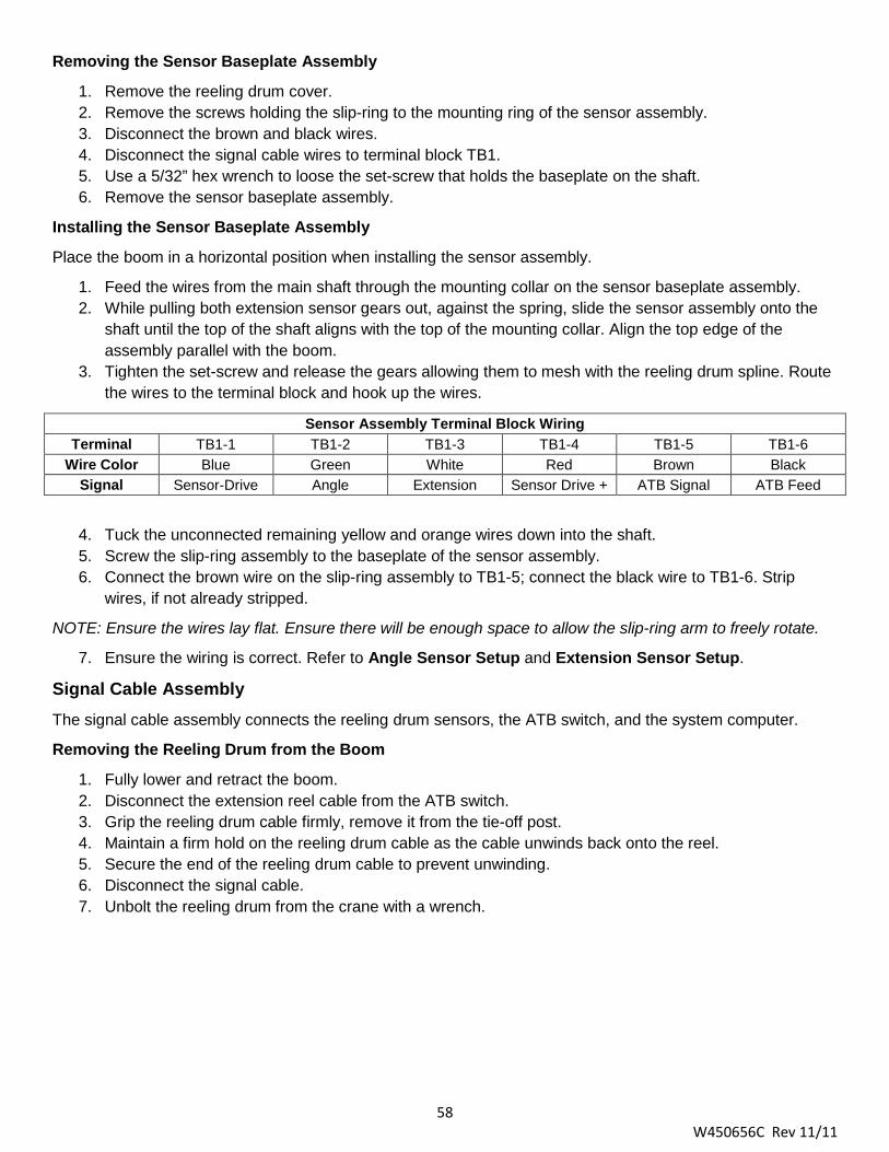
58 W450656C Rev 11/11
Removing the Sensor Baseplate Assembly
1. Remove the reeling drum cover. 2. Remove the screws holding the slip-ring to the mounting ring of the sensor assembly. 3. Disconnect the brown and black wires. 4. Disconnect the signal cable wires to terminal block TB1. 5. Use a 5/32” hex wrench to loose the set-screw that holds the baseplate on the shaft. 6. Remove the sensor baseplate assembly.
Installing the Sensor Baseplate Assembly
Place the boom in a horizontal position when installing the sensor assembly.
1. Feed the wires from the main shaft through the mounting collar on the sensor baseplate assembly. 2. While pulling both extension sensor gears out, against the spring, slide the sensor assembly onto the
shaft until the top of the shaft aligns with the top of the mounting collar. Align the top edge of the assembly parallel with the boom.
3. Tighten the set-screw and release the gears allowing them to mesh with the reeling drum spline. Route the wires to the terminal block and hook up the wires.
Sensor Assembly Terminal Block Wiring Terminal TB1-1 TB1-2 TB1-3 TB1-4 TB1-5 TB1-6
Wire Color Blue Green White Red Brown Black Signal Sensor-Drive Angle Extension Sensor Drive + ATB Signal ATB Feed
4. Tuck the unconnected remaining yellow and orange wires down into the shaft. 5. Screw the slip-ring assembly to the baseplate of the sensor assembly. 6. Connect the brown wire on the slip-ring assembly to TB1-5; connect the black wire to TB1-6. Strip
wires, if not already stripped.
NOTE: Ensure the wires lay flat. Ensure there will be enough space to allow the slip-ring arm to freely rotate.
7. Ensure the wiring is correct. Refer to Angle Sensor Setup and Extension Sensor Setup.
Signal Cable Assembly
The signal cable assembly connects the reeling drum sensors, the ATB switch, and the system computer.
Removing the Reeling Drum from the Boom
1. Fully lower and retract the boom. 2. Disconnect the extension reel cable from the ATB switch. 3. Grip the reeling drum cable firmly, remove it from the tie-off post. 4. Maintain a firm hold on the reeling drum cable as the cable unwinds back onto the reel. 5. Secure the end of the reeling drum cable to prevent unwinding. 6. Disconnect the signal cable. 7. Unbolt the reeling drum from the crane with a wrench.

59 W450656C Rev 11/11
Removing the Signal Cable from the Reeling Drum
1. Remove the reeling drum cover. 2. Remove the slip-ring on the sensor baseplate assembly. 3. Disconnect all wires from the sensor assembly except for the six wires leading to the angle and
extension sensor potentiometers. 4. To protect the sensors within the reeling drum, use two screws to temporarily reattach the cover of the
reeling drum. 5. Turn over the reeling drum with cover attached, exposing the back of the device. 6. With the wires still disconnected, pull the signal cable out of the main shaft in the center of the reel. This
cable has a strain-relief encircled with an O-ring, creating a tight fit that seals out water.
NOTE: If it is difficult to remove the cable, use an insertion/extraction tool from the front of the reeling drum to release the cable.
Installing the Signal Cable 1. Unpack the new signal cable and ensure the O-ring on the strain-relief is greased. 2. With the back of the reeling drum exposed, insert the end of the reeling drum cable with the O-ring into
the mounting plate and down the shaft in the center of the drum. 3. Seat the strain-relief, with attached O-ring using the tool provided in the kit. 4. Bend the cable to the side. Position the hollowed out section of the tool on the strain-relief plug at the
top of the shaft. 5. With a hammer, gently tap the top of the tool forcing the strain-relief into proper position in the shaft.
Continue to tap gently until the strain-relief plug will go no further. 6. Turn over the reeling drum and remove the cover. 7. Connect the wires to the terminal block on the baseplate.
Sensor Assembly Terminal Block Wiring Terminal TB1-1 TB1-2 TB1-3 TB1-4 TB1-5 TB1-6
Wire Color Blue Green White Red Brown Black Signal Sensor-Drive Angle Extension Sensor Drive + ATB Signal ATB Feed
8. Tuck the unconnected remaining yellow and orange wires down into the shaft. 9. Connect the brown wire from the slip-ring assembly to TB1-5, connect the black wire to TB1-6. Strip
wires, if not already stripped. 10. Screw the slip-ring assembly to the sensor baseplate assembly.
NOTE: Ensure the wires lay flay toward the terminal connectors. Ensure there will be enough space to clear the wires when the arm of the slip-ring rotates.
11. Replace the reeling drum cover, install the reeling drum.

60 W450656C Rev 11/11
Anti-Two-Block (ATB) Function The computer supplies a protected positive feed to the ATB switches at the boom/jib head via the signal cable, slip-ring, and reeling drum cable. With the ATB weight hanging freely on the switch(es), the switch contact is closed and the signal return to the computer is high (6.25 volts). When the weight is lifted by the hook block, the switch contact is opened, and the computer will sense a low signal input (0 volts) from the ATB signal return.
Since the computer checks the protected feed voltage internally, the system is capable of detecting a short circuit of the feed (or the ATB signal return when the switch is closed) to the crane chassis. For more information, refer to Error Codes.
Most problems with this circuit can be identified through inspection of the cables, switches, and the reeling drum. Damage to these parts may result in continous or intermittent ATB alarms.

61 W450656C Rev 11/11
Checking the Reeling Drum Cable
The outer braid of the cable carries the ATB feed to the switches. If the cable sheath is damaged, it may cause a short circuit to the boom/chassis. If this happens, fault code “B 8” will be indicated, refer to Group “B” Error Codes. The same fault code will be indicated if the ATB switch is closed and the inner core of the cable is shorted to chassis at some point in the wiring.
• Carefully inspect the reeling drum cable for wear, refer to Checking the Reeling Drum Cable Layering.
• Check for signs of damage to the outer sheath of the cable. • Check for any signs of severe “kinking” or crushing of the cable.
Checking the ATB Circuit Before continuing, ensure the connectors are correctly connected to the ATB switches at the boom head/jib. Use a bent paper clip or a piece of wire (at least two inches long) with the wire exposed on either end to jump the circuit. Refer to the image on the next page for locations corresponding to the steps below.
1. Reeling Drum Cable – Disconnect the ATB cable from the reeling drum cable. Place the jumper into the the female connector positions 1 and 5 of the reeling drum cable. If the condition stops, replace the ATB switch assembly. If the condition persists, continue to Step 2.
2. ATB Sensor Arm Terminal Block – Remove the reeling drum cover. Do not disconnect the ATB sensor arm. Place the jumper onto the ATB sensor arm terminal block postiion TB2-1B and TB2-2B. If the condition stops, replace the reeling drum cable. If the condition persists, continue to Step 3.
3. Sensor Baseplate Terminal Block – With the reeling drum cover still removed, disconnect the ATB sensor arm from the plug. Place the jumper onto the sensor baseplate terminal block position TB1-5A and TB1-6A. If the condition stops, replace the slip-ring assembly. If the condition persists, continue to Step 4.
4. Reeling Drum Cable to Computer – Disconnect the reeling drum cable from the computer cable. Place the jumper into the female connector positions A and D of the computer cable. If the condition stops, replace the computer cable. If the condition persists, replace the computer cable.
NOTE: If the condition still exists after confirming operation of the computer cable, the computer may be faulty. Do no attempt to jump pins or circuits at the computer level as this may damage the computer and void the warranty. Contact your factory representative for service or replacement.
Outrigger Position Sensors There is no troubleshooting available for the outrigger sensors. If an error code is displayed for a particular outrigger sensor, contact service for assistance. No calibration is needed.

62 W450656C Rev 11/11
Ree
ling
Dru
m
Cab
le t
o
Con
nect
ion
to
Com
pute
r
2.
ATB
Sen
sor
Te
rmin
al
Ree
ling
Dru
m
Se
nsor
Term
inal
ATB

63 W450656C Rev 11/11
WAD/ISS The WAD/ISS (Work Area Definition/Integrated Swing Sensor) incoporates a sensor housed in the swing drive of the crane that measures the angle of the upper structure of the crane relative to its carrier. The sensor measures the angle by counting electronic pulses on the target gear relative from the zero point (set by the operator) in either a positive or negative direction. The conditiong box translates the signal so it can be processed by the computer and shown in the information window of the display console.
WAD/ISS Conditiong Box
The advantage of the WAD/ISS over a typical swing potentiometer is the swing potentiometer is housed in the collector column and maintenance and/or removal is difficult. The WAD/ISS is a small unit mounted directly onto the swing drive and is easily accessible.
During normal operation, faults detected with the WAD/ISS will be shown on the display unit. During such fault conditions the red “Overload” LED will flash accomapnied by an intermittent audible beep. Additionally, the swing angle display will “ERROR” as well as the information window showing an error condition message. All swing related operator alarms, work area alarms, etc, will be displayed.
WAD/ISS Troubleshooting Table
Error Message / Problem Cause Correction “SWING SENSOR SIGNAL 1 ERROR!” “SWING SENSOR SIGNAL 2 ERROR!” “SWING SENSOR ERROR!” “SWING SENSOR LOGIC REPORT!”
Cable from sensor to condition box disconnected. Cable from sensor to conditiong box grounded.
Replace sensor.
“SWING SENSOR COMMS ERROR!”
Cable from condiiton box to computer disconnected at computer or conditiong box. Cable from condition box to computer grounded.
Check cable. Check connection at conditiong box and computer. Replace cable. If display shows load, angle, radius, etc, replace the conditioning box.

64 W450656C Rev 11/11
Intermittent, inaccurate, or no output activity
WAD/ISS too far from target within swing drive. WAD/ISS sensor too close to target within swing drive. WAD/ISS not responding normally but drawing normal current and providing normal outputs. WAD/ISS disconnected from computer.
Check sensor and sensor connection.
Replacing the Swing Sensor
Swing Sensor Removal
1. Place the boom in the rest (stowed position). 2. Turn off the power to the crane. 3. Disconnect the sensor cable from the conditioning box. 4. Loosen the sensor retaining nut. 5. Remove the sensor from the swing drive housing.
Swing Sensor Installation
1. Insert the threaded end of the sensor into the sensor port of the swing drive and screw it in until the end of the sensor contacts the gear inside the swing drive housing. Do not force the sensor any farther past this point.
2. Note the location of the index notch on the sensor. Rotate the sensor counterclockwise a ½ turn. (Illustrations on next page.)
3. Note the position of the index notch on the sensor and continue to rotate counterclockwise until the index notch reaches the ‘three o’clock’ or ‘nine o’clock’ position.
4. If the initial 180° turn puts the index notch on the ‘three o’clock’ or ‘nine o’clock’ position, continue to rotate counterclockwise until the next ‘three o’clock’ or ‘nine o’clock’ position is reached.
5. For calibration instructions, refer to Swing Sensor Setup.

65 W450656C Rev 11/11
Replacing the Conditing Box 1. Place the boom in the rest (stowed position). 2. Turn of power to the crane. 3. Disconnect the cables from the conditioning box. 4. Remove the two nuts attaching the conditiong box to the mounting bracket. 5. Install the new conditioning box onto the mounting bracket. 6. Reconnect the cables to the new conditioning box.