Thomas Christen, ABB Corporate Research, ABB Switzerland ...
W
reviewABB 4 |16
en
The corporate technical journal
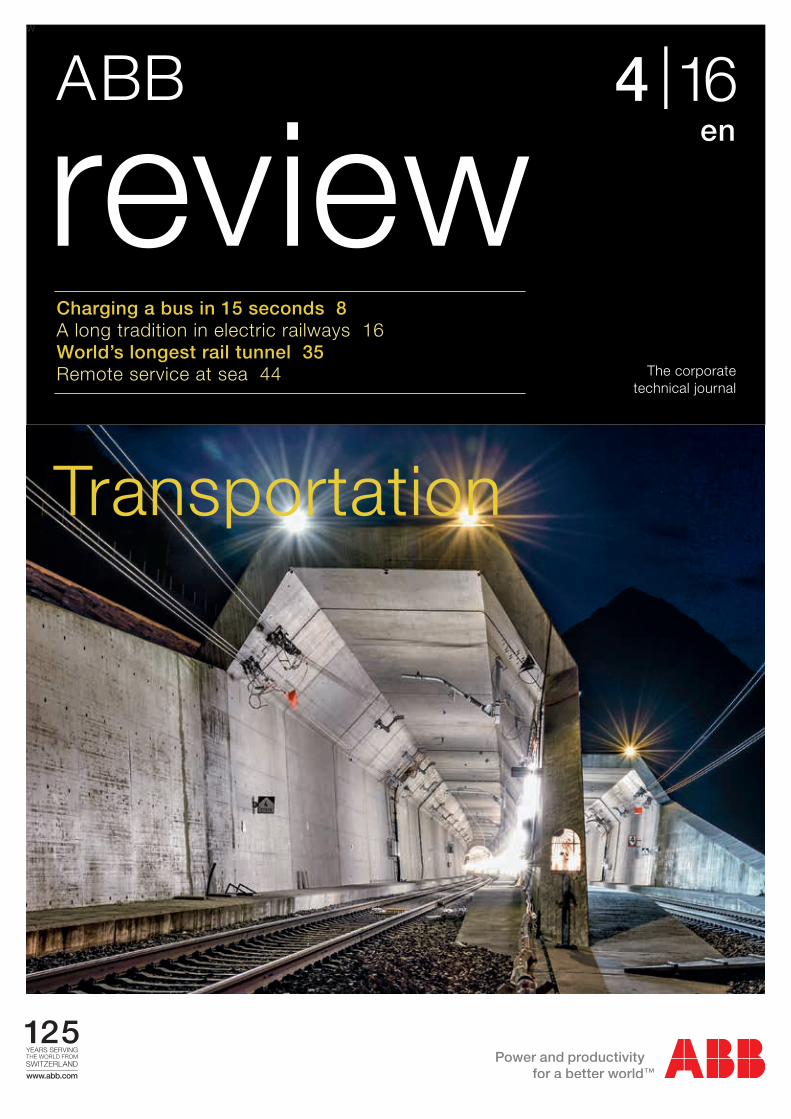
Charging a bus in 15 seconds 8A long tradition in electric railways 16 World’s longest rail tunnel 35Remote service at sea 44
Transportation

2 ABB review 4|16
Transportation and its infrastructure form one of the more visible and tangible applications of technology. The front cover shows the portal of the Gotthard base tunnel, which opened this year. The present page shows the TOSA electric bus. Both projects are discussed in articles in the present issue of ABB Review.

3
Contents
3
Cities take chargeMaking the case for the electrification of urban public transportation
Charged in a flash Optimization of batteries for a flash-charged bus
Green parkKrka national park, Croatia, is the first national park in the world to install ABB Terra 53 fast DC/AC chargers
Electrifying historyA long tradition in electric railway engineering
Weight loss programABB’s Effilight® traction transformer delivers less weight and losses and needs up to 70 percent less oil
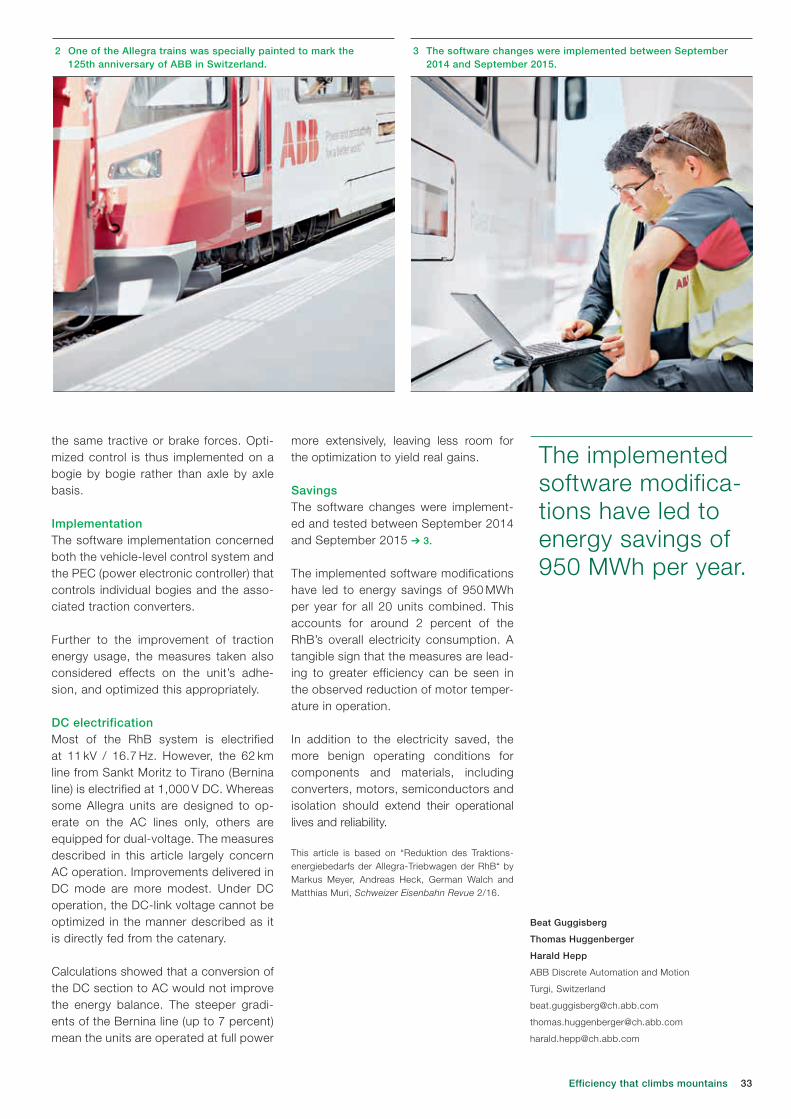
Efficiency that climbs mountainsCutting the energy consumption of the Allegra trains
Peak powerABB’s ZX0 medium-voltage switchgear and PMA cable protection for the Gotthard Base Tunnel
Record breakerABB to provide power, propulsion and automation for the world’s most advanced port icebreaker
Improving remote marine serviceA concept for the next generation ABB customer and service portal
Connect. Collaborate. OutperformAutomation & Power World returns to Houston in March 2017
Loss prophetPredicting stray losses in power transformers and optimizationof tank shielding using FEM
Wind protectionLow-voltage switching and protection strategies in wind turbines
Arc angelArc flash prevention measures increase safety
Switching the subjectA look at recent advances in IGCT technologies for high-power electronics
Grid4EULaying the groundwork for the development of tomorrow’s electricity grids
Cloud roboticsSmart robots leverage the Internet of Things, Services and People from edge to cloud
A combined futureMicrogrids with renewable power integration
2016 IndexThe year at a glance
Contents
Switching and safety
Simulation
Event
Up-time and productivity
Index
Transportation focus
6
8
13
16
25
30
35
40
44
50
51
57
63
67
72
79
84
90

ABB review 4|16 4
Editorial
For example, ABB is also at the forefront of the digitalization that enables assets and systems to share data, perform more effectively and be serviced and diagnosed remotely.
Further areas that the company is perhaps less commonly associated with include marine transportation, service offerings and the charg- ing of electric vehicles. The latter category includes the “flash charging” of electric buses. This technology involves automatically connecting and topping up a bus’s batteries at intermediate points along its route, thereby reducing the weight of batteries and thus making the system more economically com- petitive. Following a successful test opera-tion, ABB recently signed a contract to deliver the world’s first commercial “flash-charged” bus project to the Swiss city of Geneva.
I trust this issue of ABB Review will raise your awareness of and kindle your interest in the challenges of electric transportation and highlight ABB’s involvement in its ongoing development.
Bazmi HusainChief Technology Officer ABB Group
Dear Reader,The portion of the world’s population living in cities is forecast to rise from 54 percent in 2014 to 66 percent by 2050. The relent - less growth of urban centers is bringing with it numerous societal and environmental challenges. Not least among these is that of transportation. With both urban popula-tions and their affluence on the rise, more and more vehicles are competing for limited road space while contributing to pollution. On a local level, emissions from vehicles can have a detrimental impact on both human health and quality of life. On a global level, transportation contributes to about one quarter of global anthropogenic emissions of carbon dioxide. Governments are increas-ingly recognizing these challenges and implementing measures to make transporta-tion greener.
Besides pollution, transportation is also linked to congestion. Further to its nuisance aspect, congestion is an economic liability as people spend time unproductively and the delivery of goods is disrupted.
Fortunately, there are many ways to meet these challenges, ranging from hybrid or electric cars to high-capacity metros.
The electrification and energy efficiency aspects of such developments are core elements of ABB’s portfolio, but the com-pany’s abilities are far from limited to these.
Transportation
Bazmi Husain

5Editorial

6 ABB review 4|16
TIMOTHY PATEY, RETO FLUECKIGER, ALESSANDRO ZANARINI, JAN POLAND,
DAVID SEGBERS, PHILIPPE NOISETTE, BRUCE WARNER – The sustainable development of cities is pivotal for the Earth˚s future. The UN forecasts the percentage of people living in cities will rise from 54 percent in 2014 to 66 percent in 2050, [1]. During the same period, global population is forecast to reach 9.7 billion. And this population will place demands on mobility. Urban transport is already a cause of congestion and pollution today. Only an increased emphasis on sustainability in transport infrastructure can ensure tomorrow’s cities safeguard their ecology, economy, and quality of life.
Making the case for the electrification of urban public transportation
Cities take charge

7Cities take charge
Today, transportation contrib-utes nearly one quarter of glob-al CO2 emissions [2]. Climate change mitigation is being driv-
en by treaties including the Kyoto Proto-col (1997), the Copenhagen Accord (2009), and the Paris Agreement (2016). Policy makers have agreed that the aver-age global temperature rise should not exceed 2°C above the average global temperature of pre-industrial times [3]. It has been postulated that in order to assure a 50 percent probability of global warming below this limit by the end of the 21st century, the CO2 emissions be-tween 2011 and 2050 have to be limited to 1,100 gigatons [4].
The challenge is huge. The potential atmo-spheric CO2 emissions from the combus-tion of existing fossil fuel reserves would outweigh this limit by a factor of more than three [5]. Climate change mitigation policies are urgently required.
On a local level, the desire of many cities for cleaner air is also motivating change. The European Union has promoted cleaner air in cities by tightening emis-
Title picture Electrification of transportation systems contributes both to clean air in cities and to reducing carbon emissions.
sions standards for particulate matter from 0.648 g/km in 1992 (Euro I) to 0.018 g/km in 2013 (Euro VI) for transit vehicles [6]. This trend has improved air quality over the past 20 years, and will continue to do so in the years to come. But if public transportation is ever to achieve zero local emissions of particu-late matter, full electrification of the sys-tem is needed.
Moving back to the global perspective, such a drive for full electrification of pub-lic transportation will at the same time contribute to climate change mitigation (assuming the power grid is powered with a significant portion of renewable power in its mix).
This combined drive for carbon neutrality and clean air becomes increasingly press-ing with advances in urbanization and population as well as traffic challenges. Rather than building only highways, cit-ies are increasingly developing metros, trams and electric buses.
TOSA futureThe city of Geneva, Switzerland, has tak-en a key step towards full electrification of their public transportation network. The “TOSA” bus line which is presently being delivered is fully electric despite not fea-turing overhead lines. “Flash” or oppor-tunity charging [7] is used to top up the batteries at intermediate points on the route, meaning the dead weight of large batteries can be reduced, saving on both space and weight. Also, charging time is reduced at the ends of the route, which is especially important during time-con-strained rush-hour operation. The flash charging is done safely in only 15–20 s, during the time that the bus is stopped anyway to allow passengers to embark and disembark.
The absence of overhead lines is not only less visually disruptive, but also saves on installation costs by avoiding extensive construction work for the overhead line and allows for more flexible bus opera-tions during road works. It also saves on maintenance, which accounts for a sig-nificant portion of the costs of traditional bus operation using overhead line infra-structure. The TOSA bus and in particu-lar its batteries are discussed in the next article of this edition of ABB Review.
Using TOSA technology, diesel-powered bus fleets can be replaced with electric bus fleets, without the need to install overhead lines. The technology is realiz-able today, as has been demonstrated in the city of Geneva.
TOSA is just one example of what ABB has to offer. The company provides elec-trification of public transportation systems; both on-board the vehicles and off-board at the charging infrastructure. Increased electrification, in whatever form, is key to reducing emissions and achieving car-bon neutrality in all modes of transporta-tion. Many examples of this are present-ed in the present issue of ABB Review.
Timothy Patey
Reto Flueckiger
Jan Poland
Alessandro Zanarini
ABB Corporate Research
Baden-Daettwil, Switzerland
David Segbers
ABB Discrete Automation & Motion
Turgi, Switzerland
Philippe Noisette
Bruce Warner
Power Grids
Geneva, Switzerland
References[1] World Population Prospects, 2014, United
Nations.[2] Transport, Energy and CO2: Moving toward
Sustainability, 2009, International Energy Agency.[3] United Nations Framework Convention on
Climate Change (UNFCC) Report of the Con fer - ence of the Parties on its Fifteenth Session, held in Copenhagen from 7 to 19 December 2009. Part Two: Action taken by the Conference of the Parties at its Fifteenth Session. United Nations Climate Change Conf. Report 43, 2009.
[4] Meinshausen, M., et al., Greenhouse-gas emission targets for limiting global warming to 2°C. Nature, 2009. 458(7242): p. 1158–1162.
[5] McGlade, C. and P. Ekins, The geographical distribution of fossil fuels unused when limiting global warming to 2 [deg]C. Nature, 2015. 517(7533): p. 187–190.
[6] Exhaust emissions of transit buses, 2015, EMBARQ.
[7] TOSA (Trolleybus Optimisation Systeme Alimentation) 2013. 2016.

8 ABB review 4|16
TIMOTHY PATEY, RETO FLUECKIGER, JAN POLAND, DAVID SEGBERS, STEFAN WICKI –
With its six trolleybus and four tram lines, transportation in the Swiss city of Geneva already makes extensive use of electric traction. As a further step towards making its public transportation system carbon-neutral, the city has announced it will replace the diesel buses used on line 23 by a battery-powered electric bus fleet.
Optimization of batteries for a flash-charged bus
Charged in a flash
9
CC200 ➔ 4 traction and auxiliary con-verter. The convert-er can drive up to two traction motors and all the auxiliary consumers of the bus.
On a flash-charged bus, the converter
also handles the flash and opportunity charging at bus stops and the DC fast-charging at the end of the line. On an electric trolleybus, it is supplemented by a double-insulated DC-DC input converter. Adding a battery to this drive train en-ables the bus to operate free of catenary lines (overhead lines).
ABB solutions for the electrification of public transportationABB has developed a modular platform for the electric drive train of city bus-es ➔ 3. This caters to all e-bus applica-tions ranging from the traditional trolley-bus to DC fast-charged or flash-charged battery buses. At the heart of this are ABB’s highly efficient water-cooled per-manent-magnet traction motors as well as the extremely compact BORDLINE
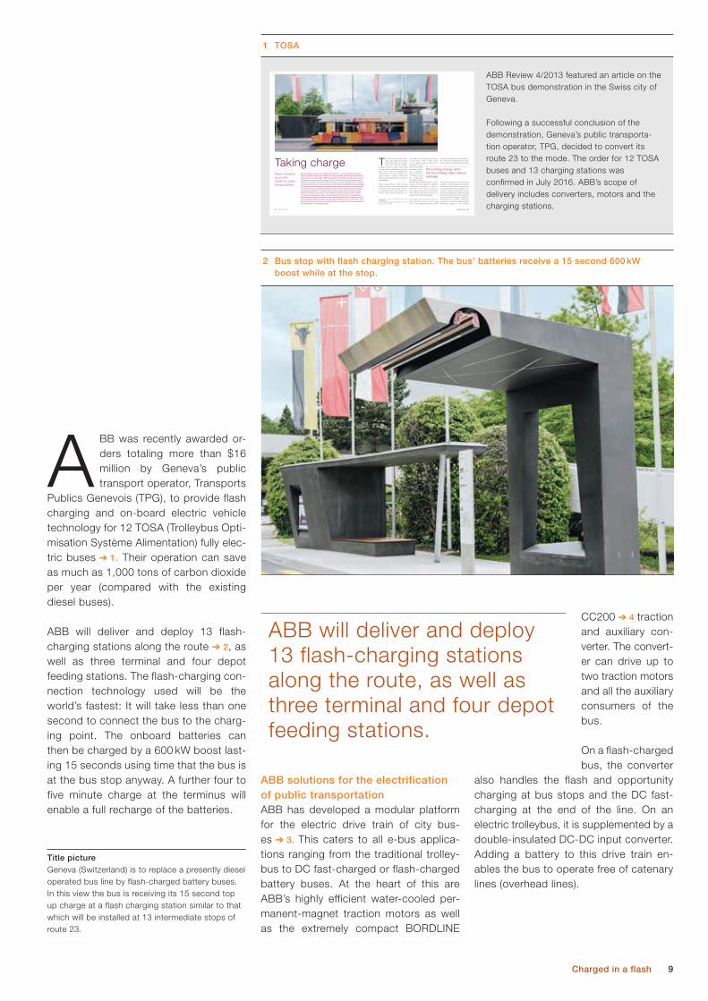
ABB was recently awarded or-ders totaling more than $16 million by Geneva’s public transport operator, Transports
Publics Genevois (TPG), to provide flash charging and on-board electric vehicle technology for 12 TOSA (Trolleybus Opti-misation Système Alimentation) fully elec-tric buses ➔ 1. Their operation can save as much as 1,000 tons of carbon dioxide per year (compared with the existing diesel buses).
ABB will deliver and deploy 13 flash-charging stations along the route ➔ 2, as well as three terminal and four depot feeding stations. The flash-charging con-nection technology used will be the world’s fastest: It will take less than one second to connect the bus to the charg-ing point. The onboard batteries can then be charged by a 600 kW boost last-ing 15 seconds using time that the bus is at the bus stop anyway. A further four to five minute charge at the terminus will enable a full recharge of the batteries.
Charged in a flash
Title picture Geneva (Switzerland) is to replace a presently diesel operated bus line by flash-charged battery buses. In this view the bus is receiving its 15 second top up charge at a flash charging station similar to that which will be installed at 13 intermediate stops of route 23.
ABB will deliver and deploy 13 flash-charging stations along the route, as well as three terminal and four depot feeding stations.
2 Bus stop with flash charging station. The bus’ batteries receive a 15 second 600 kW boost while at the stop.
ABB Review 4/2013 featured an article on the TOSA bus demonstration in the Swiss city of Geneva.
Following a successful conclusion of the demonstration, Geneva’s public transporta-tion operator, TPG, decided to convert its route 23 to the mode. The order for 12 TOSA buses and 13 charging stations was confirmed in July 2016. ABB’s scope of delivery includes converters, motors and the charging stations.
1 TOSA
65 64 ABB review 4|13
reduced acceptability of noise and pollu-tion have led manufacturers and opera-tors to think about alternatives to diesel
for powering buses ➔ 1. Solutions imple-mented to varying degrees include less conventional fuels (such as natural gas) and adopting alternative propulsion con-cepts, for example hybrid buses, battery buses and trolleybuses. A feature shared by the latter three is that they use electric motors, permitting energy to be recov-ered when the bus brakes, creating an opportunity to reduce energy wastage. Recovering energy is not, however,
tions aside, this transmission takes one of two forms: Power is either stored on the vehicle (usually in the form of diesel fuel, as on a bus) or transmitted electrically (requir-ing a continuous contact system as on metros, trams and trolleybuses). The latter forms of transportation are typically seen on heav-ily used corridors where the significant infrastructural investment is easier to justify. The former solution is typical for more lightly patronized corridors where lower startup costs permit routes to be created or modified more flexibly.
This status quo has held its own for many decades, but how much longer can it do so? Rising fuel prices and the
The world is becoming increas-ingly urban. In 2008, for the first time in the history of humanity, more than half the planet’s
population lived in cities. Cities bring with them many challenges, not least of which is the efficient organization of transportation. To avert gridlock and reduce pollution, planners across the globe are encouraging the use of public transportation.
Public transportation in cities can take numerous forms, but what they all have in common is that they require energy to be transmitted from a fixed supply to a moving vehicle. Some particular solu-
BRUCE WARNER, OLIVIER AUGÉ, ANDREAS MOGLESTUE – If you thought that charging electric vehicles was all about fiddling with charger cables followed by long and unpro-ductive waits, then think again. ABB has (together with partners) developed an electric bus that not only automatically charges in 15 s, but also provides high transportation capacity and energy efficiency. The bus connects to an overhead high-power charging contact when it pulls into a stop and tops up its batteries during the time its passengers are embarking and disembarking. Besides being an attractive means of transportation, the TOSA bus that is presently running in the Swiss city of Geneva also has numerous environmental bonuses. It is silent, entirely emissions free, uses long-life and small batteries while the visual clutter of overhead lines and pylons that is often a barrier to trolleybus acceptance is made a thing of the past. The system is inherently safe because the overhead connectors are only energized when they are engaged, and the electromagnetic fields associated with inductive charging concepts are avoided. Such has been the success of the demonstrator that the concept is now being developed for series production. Let the future begin.
Flash charging is just the ticket for clean transportation
Taking charge
Title picture The TOSA demonstration bus is presently running in public service in Geneva.
Taking charge
Recovering energy when the bus brakes helps reduce wastage.

10 ABB review 4|16
cal processes of the battery. This approach is semi-empirical, in that it relies partly on empirical/experimental results. Models based purely on physics are not suitable as the high number and complexity of the various physical and chemical inter-actions are too numerous to run compu-tations efficiently. It is more time efficient to conduct a series of well-designed ex-periments and use the results to create a model. The key to building a good model is to design the right experiments.
Step 1: Design the right experiments
In this phase, the temperatures, depth of discharge, state of charge, and current are varied in a series of battery tests. The
ple of graphite degradation are shown in ➔ 5).
A key challenge in battery integration lies in predicting the rate at which the battery will degrade. One approach is to test the batteries: The batteries are charged and discharged under various conditions to quantify the decline in capacity and rise in resistance. However, this method alone cannot cover all the use cases of the electric bus. There are too many vari-ables, including temperature, state of charge, depth of discharge / charge, and current. The time and sheer number of experiments required to cover all the use cases is simply too high.
The solution to estimating battery lifetime is to make a model informed by experi-mental results and a fundamental under-standing of the key physical and chemi-
Charging mattersAs every mobile phone users know, availability of battery power is essential if the device is to fulfil its function. The same applies to an electric bus or tram. However, after a certain time and usage, a battery needs to be replaced. A chal-lenge for ABB engineers is to predict when this will occur, and to create speci-fications that ensure availability of power through the product and system’s life.
A model informed by experimentsA battery “dies” because it fails to de-liver the power required for the specified timespan. More specifically, the decline in capacity (Ah) and rise in internal resis-tance (Ω) are simultaneous processes that compromise the battery’s ability to deliver power. This is due to chemi- cal and mechanical decomposition of the materials inside the battery (exam-
As every mobile phone user knows, availability of battery power is essential if the device is to fulfil its function.
4 ABB’s BORDLINE CC200 traction an auxillary converter.3 Key technology components of the TOSA bus.
Fully automatic energy transfer system
Two-axle drive powered by water-cooled traction motors
Water-cooledbattery pack
Water-cooledtraction converter
5 Physical and chemical degradation mechanisms of graphite within a Li-ion battery 1.
SEI is the solid electrolyte interphase formed as a consequent of electrolyte decomposition and related side reactions.
Graphite exfoliation, cracking (gas formation, solvent co-intercalation)
Graphene layer SEILi+
Donor solvent
H+
Mn2+
Electrolyte decomposition and SEI formation
SEI conversion, stabilization and growth
SEI dissolution, precipitation
Positive / negative interactions
Lithium plating and subsequent corrosion
Footnote1 Vetter, J., et al., Ageing mechanisms in
lithium-ion batteries. Journal of Power Sources, 2005. 147(1–2): p. 269-281.

11
Step 4: Apply the model
Once the model has been generated and verified, it becomes an important tool in scenario analysis. The battery’s tempera-ture, voltage, energy, and peak power all affect how a battery system should be dimensioned. While this process is not the final say in how big a battery should be, modelling informs decision makers and designers on how key variations in battery size and cooling influence bus performance.
Scenario analysisThe following scenario analysis considers a 25 ton articulated bus with a maximum passenger capacity of 80 people. There are 13 flash charging stations distributed along the route of 12 km length, providing a charging power of 600 kW for 20 sec-onds. The terminal charging uses 400 kW and takes four to five minutes. A typical load profile of such a bus is shown in ➔ 7.
Key battery requirements for this electric bus include:– 10 year lifetime– minimum charge voltage of 600 V (to
assure sufficient power is available for the motor and auxiliary systems and to match the charging infrastructure)
– cell temperature of max. 60 °C (to ensure safe operation, as the electro-lyte evaporates above 80 °C)
– charging power of 600 kW for 20s (to allow for rapid charges), and 400 kW for 5 minutes
– an energy of 46 kWh (to complete a journey in one direction, with backup power for exceptional circumstances).
Parameters for three configuration sce-narios are presented in ➔ 8.
The key to building a good model is to design the right experiments.
Charged in a flash
operation. These temperatures are essential for accu-rate electrical and aging models.
The aging model is based on the results of experi-
ments, and quantification of the decline in capacity and rise in resistance expect-ed from the many possible charge / dis-charge events.
The resulting battery model combines the electric, thermal, and aging sub-models. The interplay of these sub-mod-els enables the prediction of the change in capacity and resistance under a given load and temperature over time ➔ 6.
Step 3: Verify the model
Experiments at cell level inform and verify the model using realistic load profiles. This is an iterative process involving fur-ther refinement.
capacity decline and resistance rise are measured. This will later enable a predic-tion of how certain charge/discharge events of the battery would impact the battery aging over time and use.
Step 2:
Develop an electric, thermal, aging model
The internal electrical architecture of a Li-ion battery is complex, but electrical response is approximated with a number of resistive and capacitive components. Heat and age modify these components, as informed by the thermal and aging models.
As electric buses are power applications, Joule heating (i2R) is the dominant type of energy loss and dictates the battery cell’s wall and core temperatures during
A key challenge in battery integration is predicting the rate at which the battery will degrade.
6 Simple representation of an electrical, thermal, aging model of a Li-ion battery
7 Example of a battery load profile for one return trip of a 12km route with 13 flash charging and 2 terminal charging sections
Key operation concept is the interplay of variables between models: e.g. change in capacity (∆Q) and internal resistance (∆IR) modify the electrical model, which varies the state of charge (SoC) profile that modifies the aging model.
-300
100
300
500
-300
0 1 2 3 4 5 6
Pow
er (k
W)
Time (s)
Electrical
Thermal
Aging Voltage, capacity, and temperature over lifetime
Load (kW) &
temperature (°C)
∆Q, ∆IR
SoC profile
Losses
Cell temperatu
re
Cell tem
perature

12 ABB review 4|16
For the case of the “strong cooling” bat-tery, the battery would be fine for termi-nal charging only. However the flash charging of 580 kW is beyond the limits of the battery pack. The lower coolant temperature, however, is sufficient to maintain healthy voltage and tempera-ture ranges throughout the battery’s life-time of 12 years. This is a clear demon-stration that battery temperature matters for system lifetime performance.
The “large energy” battery is the only one of the three considered that could fulfill both the flash-charging and terminal charging requirements. For flash-charg-ing, the additional cells in series is simply needed to raise the voltage and lower the current to meet the power require-ments thronghout the battery’s life. Addi-tionally, this configuration (375s4p) would ensure healthy temperature window for the entire 10 years of the required bat-tery life.
The three battery scenarios were ana-lyzed using the thermal, electric and ag-ing battery model to forecast the lifetime and the end of life (EOL) properties. Here the EOL is defined as 80 percent of the initial capacity or 200 percent of the ini-tial resistance. The results of the model analysis shown in ➔ 8.
For the case of the “small energy” bat-tery, flash charging the battery at 600 kW would not be possible at end of life as it is beyond the power limit of the battery pack (with a C-rate limit of 8). It would be able to power the bus for some time using terminal charging only, but the rise in resistance would be too great (210 percent), resulting in an eventual unsafe temperature (T > 80°C, internal to the cell) and as well as minimum voltage of less than 600 V, which is insufficient to power the motor and auxiliary systems.
Timothy Patey
Reto Flueckiger
Jan Poland
ABB Corporate Research
Baden-Daettwil, Switzerland
David Segbers
Stefan Wicki
Discrete Automation & Motoion
Turgi, Switzerland
Use of the battery model on these three battery cases is a simple means to dem-onstrate battery design impact on main-taining a reliable system performance at end of life. Further design iterations would be done to find the optimum solu-tion, while mitigating all risks through system analysis.
Furthermore, the battery model informs the public transportation operator on the battery design impact of choosing flash charging or terminal charging. The bus line operators know their cities and its needs, and are in the best position to de-cide whether terminal or flash charging is most suited. The battery model is a sup-port tool to inform them of the battery design consequences of their system choices.9 Overview of the model calculation for the three possible battery designs for a 12 km urban
route (with flash charging). BOL = beginning of life, EOL = end of life
“Small Energy” “Strong Cooling” “Large Energy”
BOL EOL BOL EOL BOL EOL
EOL - 6 y - 12 y - 10 y
Capacity 100% 83% 100% 80% 100% 80
Resistance 100% 200% 100% 170% 100% 185%
Energy content 58 kWh 48 kWh 58 kWh 46 kWh 69 kWh 55 kWh
Voltage range 690 - 850 V 590 - 850 V 690 - 850 V 630 - 850 V 840 - 1010 V 770 - 1010 V
C-rate terminal (continuous) 5.3 6.2 5.3 6 5.4 5.6
C-rate flash (for 20 s) 8 8.5 8 8.3 6.8 7
Peak core cell temperature 57 °C 86 °C 43 °C 58 °C 44 °C 57 °C
Battery efficiency 90% 80% 90% 85% 92% 86%
8 Overview of three possible battery designs for a 12 km urban route (with flash charging)
Design criteria “Small energy” “Strong cooling” “Large energy”
Cell chemistry LTO LTO LTO
Max. C-rate permitted (continuous) 6 6 6
Max. C-rate permitted (for 20s) 8 8 8
Cells in series / in parallel 314 / 4 314 / 4 375 / 4
Energy content [kWh] 58 58 69
Minimum voltage [V] 630 630 750
Nominal cont. power [kW] 400 400 480
Nominal 20s power [kW] 580 580 690
Battery weight incl. cooling system [kg] ~1600 ~1600 ~2000
Coolant temperature [°C] 25°C 15°C (active) 25°C
C-rate is the rate at which a battery discharges, with 1 C-rate equal to a complete discharge in 1 hour, and 10 C-rate 1/10th of 1 h, (ie, 6 minutes).

13Green park
Green parkKrka National Park, Croatia, is the first national park in the world to install ABB Terra 53 fast DC/AC chargers
ALEKSANDAR RADOSAVLJEVIC, MERSIHA VELIC HAJDARHODZIC,
MICHELLE KIENER – Krka National Park, situated in Šibenik-Knin county in Croatia, is a world famous natural phenom-enon with its seven waterfalls of the Krka River. On the park’s territory there are many historical and cultural monuments, one of them is the remains of the hydro power plant Jaruga, the oldest power generating facility in the world, built in 1895. That was the first alternating current (AC) power system in
Croatia, the first in Europe and the second in the world, coming online only two days after the Niagara Falls AC plant. To protect its nature and heritage Krka National Park has invested in five electric vehicles and four ABB DC electric vehicle fast-charging stations: Terra 53 CJG. The first unit is already installed and it is operating every day at Lozovac, nearby the town of Šibenik and the hydro plant Jaruga.

14 ABB review 4|16
“This is a step forward in nature conserva-tion, and we are particularly proud that the Public Institution of Krka National Park joined the Green Line project, which pro-vides protected areas the opportunity to serve as a model for the introduction and broader user of electric vehicles. We hope that the project will continue to develop, to allow greater numbers of citizens to be-come direct contributors to environmental protection through the purchase of electric vehicles,” stressed Krešimir Šakic, direc-tor of the Public Institution of Krka NP.
The electric vehicle charging infrastructure is a Terra DC 53 multi-standard 50 kW modular station with one, two or three
plugs for the rapid charging of elec-tric vehicles. The flexible design en-ables multi-proto-col charging, ie, CCS, CHAdeMO and fast charging AC standards, to meet the individual needs of each customer. The sta-tions are designed
for super-rapid charging and are ideal for use at petrol stations and in urban city areas with high vehicle traffic.
Park firstThe first station came online in Septem-ber 2016 and is particularly special be-
The stations are set to charge two cars at the same time and charging lasts for a duration of 0.5 to 1.5 hours, depending on the capacity of the vehicle battery. The ABB chargers are equipped with inter-net based connected services and allow users to easily connect to different soft-ware systems and payment platforms. The connectivity also enables remote monitor-ing, maintenance and functionality add-ons. The working temperature of the charging stations is from – 35 °C to + 50 °C.
Green lineThe initiative is part of the “Green Line” program, launched by the Ministry of En-vironmental and Nature Protection and
the Environmental Protection and Energy Efficiency Fund which is intended for public institutes managing protected areas, national parks and nature parks.
Krka National Park (Krka NP) is home to numerous endemic plants, geomorphological forms of rocks and animal species
and covers a total area of 109 km2. It is challenging to maintain and preserve natural rarities and therefore the park managers undertake constant efforts in order to keep the high level of conserva-tion of these natural treasures. One as-pect of this work has been the initiative to use electric and hybrid plug-in vehi-cles within the park and to provide fast DC charging stations. The first charging station is already in operation in Lozo-vac ➔ 1. The next charging station will be installed as part of the new information center at Laškovica above Roški slap and the remaining stations will be strate-gically placed at a variety of loca tions within the park.
An even greener parkThe missions of Krka NP include reduc-ing CO2 emissions, as well as reducing noise, fuel consumption and mainte-nance costs. To invite all park visitors to be part of the efforts to protect the envi-ronment, the charging stations will be available for all visitors with electric cars.
1 ABB’s Terra 53 CJG charging station at Lozovac
Title picture Krka National Park lies within Šibenik-Knin County, and covers a total area of 109 km²
The electric vehicle charging infrastructure is a Terra DC 53 multi-standard 50 kW modular station with one, two or three plugs for the rapid charging of electric vehicles.
15Green park
ture and appreciate the work being done to conserve a national park, as well as the wider environment. In Krka NP there is no war of the currents. Simply a moti-vation to provide sustainable infrastruc-ture, where the quiet hum of an EV en-
cause it’s the first ABB fast electric vehicle charging station installed in any national park in the world. In addition, Krka NP is one of the first European parks to install electric vehicle charging stations.
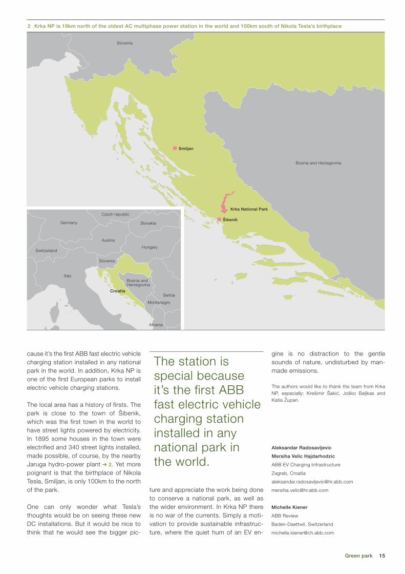
The local area has a history of firsts. The park is close to the town of Šibenik, which was the first town in the world to have street lights powered by electricity. In 1895 some houses in the town were electrified and 340 street lights installed, made possible, of course, by the nearby Jaruga hydro-power plant ➔ 2. Yet more poignant is that the birthplace of Nikola Tesla, Smiljan, is only 100km to the north of the park.
One can only wonder what Tesla’s thoughts would be on seeing these new DC installations. But it would be nice to think that he would see the bigger pic-
Aleksandar Radosavljevic
Mersiha Velic Hajdarhodzic
ABB EV Charging Infrastructure
Zagreb, Croatia
Michelle Kiener
ABB Review
Baden-Daettwil, Switzerland
The station is special because it’s the first ABB fast electric vehicle charging station installed in any national park in the world.
gine is no distraction to the gentle sounds of nature, undisturbed by man-made emissions.
The authors would like to thank the team from Krka NP, especially: Krešimir Šakic, Joško Baljkas and Katia Zupan.
Italy
Slovenia
Bosnia and Herzegovina
Krka National Park
Smiljan
2 Krka NP is 18km north of the oldest AC multiphase power station in the world and 100km south of Nikola Tesla’s birthplace
Šibenik
Italy
Austria
Czech republic
Germany
France
Hungary
Slovakia
Montenegro
Serbia
Albania
Slovenia
Bosnia and Herzegovina
Switzerland
Croatia

16 ABB review 4|16
NORBERT LANG – It may come as a surprise that long before the emer-gence of globalization technical developments in different countries of the western world occurred largely in parallel, despite differences in conditions and mentalities. This is definitely true for the development of railway electrification and vehicles. Depending on whether a country had rich coal deposits or huge hydropower resources, the reasons to electrify railways would have differed. Even so, many notable innova-tions occurred simultaneously yet independently.
A long tradition in electric railway engineering
Electrifying history
Historical perspective

17Electrifying history
head contact wires centered above the track could not be approved due to the high voltage, the contact wire was car-ried laterally on wooden poles. As agreed before the commencement of the trial,
the electrification was removed after completion of the trial and the line reverted to steam operation (it was finally electri-fied in 1942). However, experiences gained were to have far-reaching consequences.
to supply the mechanical part (ie, body, frame and running gear) of practically all Swiss electric locomotives. Brown’s two sons, Charles E. L. and Sidney Brown also worked on equipment for electric loco motives (It was Charles Brown who later cofounded BBC.) Together the two sons designed the first mainline electric locomotive for the 40 km Burgdorf–Thun railway ➔ title picture. This was a freight locomotive with two fixed speeds (17.5 and 35 km/h) powered by 40 Hz three-phase AC. The transmission used straight-cut gears and had to be shifted during standstill. Two large induction motors drove the two axles via a jackshaft and coupling rods. The overhead line voltage was limited to a maximum of 750 V by law.
In 1903, ABB Sécheron’s predecessor company CIEM (Compagnie de l’Industrie Electrique et Mécanique) electrified the narrow-gauge railway from St-Georges-de-Commiers to La Mure in France using direct current at an exceptionally high voltage (for the time) of 2,400 V using a double overhead contact wire system. Almost simultaneously yet independently, Maschinenfabrik Oerlikon (MFO) and BBC each initiated a landmark electrification project on the Swiss Federal Railway (SBB) network.
MFO: Single-phase alternating currentBetween 1905 and 1909, MFO tested a single-phase 15 kV/15 Hz electrification on a section of the former Swiss “National-bahn” railway between Zurich-Seebach and Wettingen (now part of the Zurich suburban network). The first locomotive used was equipped with a rotary con-verter and DC traction motors ➔ 3. In 1905, a second locomotive was add-ed ➔ 4. This used the same axle arrange-ment (B’B’), but the bogies both had a 180 kW single-phase series-wound motor fed directly from the transformer’s tap changer. (Tap-changer control was in later years to become the standard con-trol method for AC locomotives and was not to be displaced until the advent of power electronics.) The axles were driven via a speed-reduction gear, jackshaft and coupling rods. The maximum speed was 60 km/h. The motors used salient stator poles and phase-shifted field com-mutation. This locomotive performed so well that the earlier locomotive was adapt-ed accordingly. Between December 1907 and 1909 all regular trains on this line were electrically hauled. Because over-
For most manufacturers, the de-velopment of electrification tech-nology started with tramways. In 1890, a predecessor of ABB’s
business in Sécheron, Switzerland, sup-plied France’s first electric tramcars to Clermont-Ferrand ➔ 1. These were soon followed by the world’s first electrically operated mountain rack railways. In 1898 another ABB predecessor, BBC, equipped several mountain railways, including the world-famous Jungfraubahn climbing to the 3,500 m-high Jungfraujoch, using a 40 Hz (later 50 Hz) three-phase system.
Although local transport systems and mountain railways have also undergone huge technical developments since the early years, this article will focus on de-velopments on standard-gauge mainline railways.
Electrification with different power systemsIt is a little-known fact that it was Charles Brown Sr. (1827–1905), whose name lives on as one of the B’s in ABB, who founded SLM ➔ 2 in 1871. The company produced steam and mountain railway locomotives and for many decades was
1 Early milestones
– 1890: A predecessor company of ABB Sécheron in Geneva supplies the first electric tramcars in France to the city of Clermont-Ferrand.
– 1892: The world’s first electric rack railway is installed at the Mont-Salève near Geneva, using 500 V DC.
– 1894: Maschinenfabrik Oerlikon (MFO) supplies the first electric tramcars to Zurich.
– 1896: BBC builds electric tramcars for the Swiss city of Lugano. The Swedish ABB predecessor company ASEA, founded in 1883, starts its electric traction business with tramcars.
– 1898: BBC equips the Stansstaad–Engel-berg and Zermatt–Gornergrat mountain railways as well as the Jungfraubahn to the summit of the Jungfraujoch at 3,500 m above sea level.
– 1901: ASEA supplies electrified tramcars to the city of Stockholm.
The electric trac-tion vehicle in par-ticular, in a way the most harmonic and most beautiful means of electrical and mechanical engineering, con-sistently presents new and very inter-esting design prob-lems to be solved.Karl Sachs
Title pictureThe first mainline electric locomotive for the 40 km Burgdorf–Thunrailway (1899).

18 ABB review 4|16
controlled using switchable stator poles. The low-mounted low-speed motors drove the axles via multi-part coupling rods. The locomotives had an hourly rating of 780 kW and 1,200 kW respectively and a top speed of 75 km/h. Until all locomo-tives were completed, three locomotives of a similar design were rented from the Valtelina railway.
At the time it was already realized that asynchronous AC motors offered several advantages for traction applications, in-cluding robustness and simpler mainte-nance due to the absence of a commu-tator. Disadvantages, however, included the coarse speed graduation resulting from pole switching and the double-wire overhead line of the three-phase supply, which added to the complexity of turn-outs. Three-phase motors were thus to remain relatively rare in traction applica-tions until recent times when power elec-tronic converters were able to alleviate
BBC: Electric power for the Simplon tunnelIn late 1905, BBC decided to electrify (at its own cost and risk) the 20 km single-track Simplon tunnel under the Alps be-tween Brig (Switzerland) and Iselle (Italy), which was then approaching comple-tion. An important argument for electrifi-cation was the risk that carbon monoxide from steam locomotives could present to passengers should a train break down in the long tunnel. However, only six months remained until the tunnel’s inauguration. Electrification was carried out using a three-phase supply at 16 2/3 Hz / 3 kV fed from two dedicated power stations locat-ed at either end of the tunnel. The same power system was also adopted on the Valtelina railway in Northern Italy, the Brenner and the Giovi lines as well as the line along the Italian Riviera. The initial fleet comprised two loco motives of type Ae 3/5 (1’C 1’) ➔ 5 and two Ae 4/4 (0-D-0), all using induction motors. Speed was
3 MFO experimental locomotive no. 1 with rotary converter and DC traction motors
4 MFO experimental locomotive no. 2 with single-phase traction motors
2 Abbreviations of railway and manufacturing companies
ASEA Allmänna Svenska Elektriska Aktiebolaget, Västeras, Sweden (1983–1987). In 1988, ASEA merged with BBC to form ABB.
BBC Brown, Boveri & Cie. AG, Baden, Switzerland (1891–1987)
BLS Bern-Lötschberg-Simplon Railway, Spiez, Switzerland
CIEM Compagnie de l’Industrie Electrique et Mecanique
DB Deutsche Bahn AG (German Railways)
MFO Maschinenfabrik Oerlikon AG (1876–1967). Acquired by BBC.
ÖBB Österreichische Bundesbahnen (Austrian Federal Railways)
SAAS Société Anonyme des Ateliers de Sécheron, Geneva, Switzerland (1918–1969). Acquired by BBC.
SBB Schweizerische Bundesbahnen (Swiss Federal Railways)
SLM Schweizerische Lokomotiv- und Maschinenfabrik, Winterthur, Switzerland (Swiss Locomotive and Machine Works, est. 1871). Acquired by Adtranz in 1998.
SJ Statens Järnvägar (Swedish State Railways, became a public limited company in 2001)
Walter Boveri objected to the operation of utility and railway grids at different fre-quencies. Among others, his inter-vention led to the compromise of using 16 2/3 Hz for railways.

19Electrifying history
Boveri also suggested equipping loco-motives with mercury-arc rectifiers, a technology that had already proven itself in industrial applications. However, the time was not yet ripe for converter tech-nology on railway vehicles as the volumi-nous mercury containers would hardly have been able to withstand the tough operating conditions.
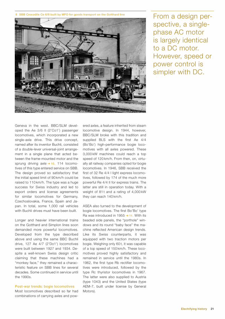
The electrification of the Gotthard line progressed so rapidly that there was vir-tually no time to adequately test the trial locomotives. Orders had to be placed quickly. BBC/SLM supplied 40 passenger train locomotives (1’B)(B1’), and MFO/SLM supplied 50 freight locomotives (1’C)(C1’). Both types were equipped with four frame-mounted motors driving the axles via a jackshaft and coupling rods. With an hourly rating of 1,500 and 1,800 kW and top speeds of 75 and 65 km/h respec-tively, these locomotives were able to ful-fill expectations and handle traffic for a long time to come. In fact, these Gotthard loco-motives became iconic among Swiss trains. This is particularly true for the 20 m long freight version with articulated frames, the so-called Crocodiles ➔ 8, which con-tinued in service for nearly 60 years. This type has been copied in various forms in different countries, and even today it is still a “must” on every presentable model railway.
Contributions by SécheronIn 1921/22 ABB’s predecessor company, Sécheron, supplied six Be 4/7 locomo-tives (1’Bo 1’) (Bo’) for the Gotthard rail-way. They were equipped with four indi-vidually driven axles with Westinghouse quill drives ➔ 9. Despite their good run-
In 1910, MFO and SLM jointly supplied a 1,250 kW prototype locomotive to BLS with a C-C axle arrangement ➔ 7. Follow-ing successful trials, BLS ordered sever-al Be 5/7 (1’E1’) 1,800 kW locomotives, the first of which was delivered in 1913. In 1930, SAAS supplied the first of six Ae 6/8 (1’Co)(Co1’) locomotives using the proven single-axle quill drive to BLS. These pulled heavy passenger and goods trains until well after the second world war.
Electric operation on the Gotthard lineIn view of the shortage of coal during the first world war, in 1916 SBB decided to electrify the Gotthard railway using the power system that had already proven itself on the Lötschberg line. SBB asked
the Swiss machine and electrical in-dustry to provide prototype locomo-tives with a view to of later winning orders. To ensure the line’s power supply, the con-struction of three high-pressure hy-drostorage power plants (Amsteg,
Ritom and Barberine) was commenced immediately.
BBC’s cofounder Walter Boveri vehe-mently objected to the operation of na-tional utility and railway grids at different frequencies. Among others, his interven-tion led to the compromise of using 16 2/3 Hz (= 50 Hz ➔ 3) for railways.
their shortcomings without compromis-ing their strengths.
In 1908, the SBB took over the installa-tion. In 1919 two further locomotives were added and the electrification ex-tended to Sion. A second tunnel bore was completed in 1921. The three-phase era on the Simplon ended in 1930 when the line was converted to the standard single-phase 15 kV / 16 2/3 Hz ➔ 6.
Electrification of the Lötschberg railwayWith gradients of 2.2 to 2.7 percent and curve radii of 300 m, the railway from Thun via Spiez to Brig operated by BLS and completed in 1913 has a distinct mountain railway character. From an early
stage, it was intended to operate the twin-track Lötschberg tunnel electrically. As early as 1910, BLS decided in favor of the 15 kV / 15 Hz system of the Seebach–Wettingen trial. The frequency was later increased to 16 2/3 Hz. The BLS thus paved the way not only for the later elec-trification of the Gotthard railway but also for the electrification of railways in Ger-many, Austria and Sweden, all of which adopted this system.
5 BBC three-phase AC locomotive of the Simplon tunnel line, 1906 6 Determining the optimal electrification system
In 1904 the “Schweizerische Studienkommis-sion für den elektrischen Bahnbetrieb” (Swiss Study Commission for Electric Railway Operation) was formed to “study and clarify the technical and financial prerequisites for the introduction of an electric service on Swiss railway lines.” Different railway electrification systems were investigated in detailed studies, taking into account recent experience. Results and findings were published on a regular basis. In 1912, the commission concluded that a single-phase current system using an overhead line with 15 kV and approximately 15 Hz was the preferable system for the electrification of Swiss main lines.
AC motors offered several advantages for traction appli-cations, including robustness and simpler maintenance due to the absence of a commutator.

20 ABB review 4|16
By 1920, the electrification had been ex-tended via Gellivare to Lulea on the Gulf of Bothnia. The Norwegian section of the line was electrified in 1923. The moun-tains traversed are of medium height, and the gradients of 1.0 to 1.2 percent are considerably lower than those on Swiss mountain railways. However, the heavy ore trains placed high demands on the locomotives. ASEA supplied the electrical equipment for 12 1,200 kW articulated locomotives (1’C)(C1’) with side-rod drive, as well as for two similar 600 kW express locomotives (2’ B 2’). 10,650 kW four-axle locomotives for ex-press goods services were later added and mainly operated in pairs. In 1925 the 460 km SJ mainline between Stock-holm and Gothenburg was electrified, with ASEA supplying the 1,200 kW 1’C1’locomotives.
Successful single-axle driveAfter commissioning the electric service on the Gotthard line, SBB extended its
railway electrification onto the plains and into the Jura mountains. By 1927, con-tinuous electric operation was possible from Lake Constance in the east to Lake
ning characteristics, no further units were ordered as SBB was initially wary of the single-axle drive. For its less moun-tainous routes, SBB ordered 26 Ae 3/5 (1’Co 1’) passenger locomotives with an identical quill drive and a top speed of 90 km/h. Weighing 81 t, these machines were considerably lighter than other types. Ten similar units with a 2’Co 1’ wheel arrangement (Ae 3/6 III) followed later. These three types were generally referred to as Sécheron machines and were mainly used in western Switzer-land. The last were still in operation in the early 1980s when they were mostly to be found on the car transporter trains of the Gotthard and Lötschberg tunnels.
ASEA’s activities in the railway sectorSimilarly to Switzerland, electrification of the Swedish state railways started be-fore the first world war. From 1911 until 1914, the 120 km long so-called Malm-banan or “ore line” was electrified. Its main purpose was to transport magne-tite ore from mines in Kiruna to the port of Narvik (Nor-way), a port that remains ice-free all year due to the Gulf Stream. Swe-den has huge hy-dropower resources. The Porjus hydro-power plant supplies the power for this railway, which is operated with single-phase 15 kV at 16 2/3 Hz (initially 15 Hz).
7 Trial locomotive for the Lötschberg railway, 1910
The so-called Crocodile locomotives became iconic among Swiss trains.
Electrification of the Swedish state railways started before the first world war.
21Electrifying history
ered axles, a feature inherited from steam locomotive design. In 1944, however, BBC/SLM broke with this tradition and supplied BLS with the first Ae 4/4 (Bo’Bo’) high-performance bogie loco-motives with all axles powered. These 3,000 kW machines could reach a top speed of 120 km/h. From then, on, virtu-ally all railway companies opted for bogie locomotives. In 1946, SBB received the first of 32 Re 4/4 I light express locomo-tives, followed by 174 of the much more powerful Re 4/4 II for express trains. The latter are still in operation today. With a weight of 81 t and a rating of 4,000 kW they can reach 140 km/h.
ASEA also turned to the development of bogie locomotives. The first Bo’Bo’ type Ra was introduced in 1955 ➔ 11. With its beaded side panels, the “porthole” win-dows and its round “baby face” the ma-chine reflected American design trends. Like its Swiss counterparts, it was equipped with two traction motors per bogie. Weighing only 60 t, it was capable of a top speed of 150 km/h. These loco-motives proved highly satisfactory and remained in service until the 1980s. In 1962, the first type Rb rectifier locomo-tives were introduced, followed by the type Rc thyristor locomotives in 1967. The latter were also supplied to Austria (type 1043) and the United States (type AEM-7, built under license by General Motors).
Geneva in the west. BBC/SLM devel-oped the Ae 3/6 II (2’Co1’) passenger locomotives, which incorporated a new single-axle drive. This drive concept, named after its inventor Buchli, consisted of a double- lever universal-joint arrange-ment in a single plane that acted be-tween the frame-mounted motor and the sprung driving axle ➔ 10. 114 locomo-tives of this type entered service on SBB. The design proved so satisfactory that the initial speed limit of 90 km/h could be raised to 110 km/h. The type was a huge success for Swiss industry and led to export orders and license agreements for similar locomotives for Germany, Czechoslovakia, France, Spain and Ja-pan. In total, some 1,000 rail vehicles with Buchli drives must have been built.
Longer and heavier international trains on the Gotthard and Simplon lines soon demanded more powerful locomotives. Developed from the type described above and using the same BBC Buchli drive, 127 Ae 4/7 (2’Do1’) locomotives were built between 1927 and 1934. De-spite a well-known Swiss design critic claiming that these machines had a “monkey face,” they remained a charac-teristic feature on SBB lines for several decades. Some continued in service until the 1990s.
Post-war trends: bogie locomotivesMost locomotives described so far had combinations of carrying axles and pow-
From a design per-spective, a single-phase AC motor is largely identical to a DC motor. However, speed or power control is simpler with DC.
8 SBB Crocodile Ce 6/8 built by MFO for goods transport on the Gotthard line

22 ABB review 4|16
motives have an hourly rating of nearly 5 MW and have proven themselves ex-tremely well. One machine was modified with thyristor-based converters and suc-cessfully tested on the Austrian Sem-mering line. As a result, ÖBB ordered 216 locomotives of a similar design (type 1044) from ABB in Vienna.
The combination of frequency converters and asynchronous motors proved to be particularly advantageous. It allowed a largely uniform drive concept to be real-ized that was essentially independent of the type of power supplied by the con-tact wire. This enabled some standard-ization and also made it easier to build locomotives able to work under different voltages and frequencies for internation-al trains. Furthermore, the use of robust three-phase induction motors saved on maintenance due to the absence of com-mutators while also offering a higher power density, meaning motors could either be made smaller or more powerful. Examples of BBC and ABB locomotives using this arrangement are the E120 of DB, the Re 4/4 of Bodensee-Toggenburg and the Sihltal railways (Switzerland), the Re 450 and Re 460 of SBB and the Re 465 of BLS.
High-speed trainsBetween 1989 and 1992, German rail-ways (DB) commissioned 60 ICE (Inter-city Express) trains, which were based on the technology of the E120. ABB was involved in their development. The trains consisted of two power cars with con-verter-controlled three-phase induction
From rectifier to converter technologyFrom a design perspective, a single-phase AC motor is largely identical to a DC motor. However, speed or power control is simpler with DC. While some countries chose to electrify their mainline networks with DC using a voltage of 1,500 or 3,000 V, others sought to ac-quire locomotives with onboard rectifiers converting the AC supply to DC. One of the downsides of DC electrification is that the line voltage must be relatively low as transformers cannot be used. This leads to higher conduction losses requiring more frequent substations. Manufacturers thus long sought ways of combining DC traction with AC electrifi-cation (see also MFO’s first Seebach-Wettingen locomotive described above). It was not until vacuum-based singe-an-ode mercury tubes (so-called ignitrons or excitrons) were developed that rectifier locomotives were built in large numbers (mostly in the United States and some Eastern Bloc countries).
The semiconductor revolution in elec-tronics was to change this, and solid-state components soon found their way into locomotives. Between 1965 and 1983, BLS purchased 35 Re 4/4, series 161 locomotives ➔ 12. Instead of using single-phase AC, the traction motors were fed with half-wave rectified and re-actor-smoothed DC. The oil-cooled sol-id-state diode rectifier was fed from the transformer tap changer. These locomo-tives had two traction motors per bogie, connected in parallel to reduce the risk of slippage on steep inclines. The loco-
9 Sécheron type single-axle quill drive (Sécheron)
10 Buchli single-axle drive manufactured by BBC (BBC 12395)
The motor shaft attached to the upper cog and the axle to the lower.
The springing helped decouple the movement of the axle from that of the motor, reducing track wear.
Today, ABB has strategic agree-ments with several major players in the rolling stock market and sup-plies state-of the-art components for a wide range of uses.

23
This article originally appeared in ABB Review 2/2010 and was brought up to date by ABB Review staff for the present anniversary.
motors and 11 to 14 intermediate pas-senger cars. During a trial run on the newly completed high-speed line be-tween Hamburg and Frankfurt, one of these trains reached a speed of 280 km/h.
In 1990, ABB supplied the first of 20 X2000 tilting high-speed trains to SJ for the express service between Stockholm and Gothenburg. They use GTO converters and induction motors and can reach 200 km/h. The type is now also used on other lines in Sweden, enabling reductions in journey times of up to 30 percent.
Streamlining the railway businessArguably, no other products of the ma-chine or electrical industry were consid-ered as prestigious by the general public as railway vehicles, and although exports did occur, administrations generally pre-ferred to buy from domestic suppliers. However, this paradigm began to change in the late 1980s and 1990s. Notably, the prefabrication of parts allowed consider-able reductions of lead times. Further-more, such prefabricated subassemblies permit final assembly to be carried out virtually anywhere. For the industry, this shift – combined with market liberaliza-tion – resulted in a transition from com-plete manufacturing for a local market to component delivery for a global market.
The ABB railway business todayFollowing the merger of ASEA and BBC to form ABB, the respective transporta-tion system businesses were formed into an independent company within the ABB Group. In 1996, ABB and Daimler Benz merged their railway activities under the name ABB Daimler-Benz Transportation
Norbert Lang
Archivist
ABB Switzerland
Further reading– Bugli, Ralph W. (ed.). (1983) Electrifying
Experience. A Brief Account of The ASEA Group of Sweden 1883–1983.
– Haut, F. J. G. (1972) Die Geschichte der elektrischen Triebfahrzeuge. Vol. 1.
– Huber-Stockar, E. (1928) Die Elektrifikation der Schweizer Bundesbahnen.
– Machefert-Tassinn, et al. (1980) Histoire de la traction electrique, 2 vols.
– Sachs, K. (1973) Elektrische Triebfahrzeuge. 3 vols.
– Schneeberger, H. (1995) Die elektrischen und Dieseltriebfahrzeuge der SBB, Vol. I: Baujahre 1904–1955.
– Teich, W. (1987) BBC-Drehstrom-Antriebstechnik fur Schienenfahrzeuge, Mannheim.
– (1988–2016) ABB Review.– (1924–1987) ASEA Journal (engl. ed.).– (1914–1987) BBC Mitteilungen – (1928–1943, 1950–1987) BBC Nachrichten – (1921–1970) Bulletin Oerlikon.– (1929–1972) Bulletin Secheron
12 Re 4/4, series 161 rectifier locomotive of BLS, 196511 ASEA type Ra bogie locomotive of the Swedish State Railways
d = 1,300
2,200 2,2002,900
1 2
3 3
2,9004,900
15,100
7,800
Electrifying history
(Adtranz). Adtranz also acquired the Swiss companies SLM and Schindler Waggon in 1998. In 1999, ABB sold its stake in Adtranz to DaimlerChrysler which later sold its railway sector to Bombardier. Thus today, ABB no longer builds complete locomotives, but contin-ues to supply different high-performance components for demanding traction ap-plications.
Since 2002 ABB has maintained a close strategic cooperation with Stadler Rail. Stadler is an internationally operating rolling stock manufacturer that emerged from a small Swiss company, which orig-inally produced diesel and battery-elec-tric tractors for works railways and in-dustrial lines. The company is now an important international supplier of multi-ple unit passenger trains for both inter-city and commuter service. The compa-ny also supplies trams, metros and other types of trains to customers across the world. In recent years ABB has devel-oped new components for different over-head line voltages and frequencies as well as for diesel-electric traction appli-cations. ABB supplies the transformers, traction converters, onboard power sup-ply systems and battery chargers used on Stadler trains.
Today, ABB also has strategic agreements with several other global players in the roll-ing stock market and supplies state-of-the-art components for a wide range of uses, fulfilling the most stringent demands. In the spirit of the company’s founders, ABB remains at the forefront of developing innovative solutions for an ever-developing market.

24 ABB review 4|16

25
ABB has developed a hybrid transformer concept where there is a small oil tank around the winding, while the core remains in the air.
Traction transformers take up valuable train space and add weight to the train, so the moti-vation to reduce their size and
weight is strong. However, the constraints applied by the law of physics are also strong. The transformer core must have certain dimensions in order to accom-modate the magnetic field. In addition, weight constraints make traction trans-formers less efficient because the amount of copper and iron must be limited. On traditional trains pulled by locomotives, the heavy transformer is not necessarily a disadvantage as it contributes to adhe-sion: the maximum force that the loco-motive can apply to pull a train with-out losing adhesion on the rails is limit-ed by the weight of the locomotive. In modern passenger trains, however, there is a tendency toward multiple unit trains where the traction equipment is not concentrated in the locomotive but distributed along the length of the train in the same vehi-cles which passengers travel [2]. This brings considerable benefits in terms of adhe-sion and acceleration, but also requires
TOUFANN CHAUDHURI, MARIE-AZELINE
FAEDY, STEPHANE ISLER, MICHELLE
KIENER – Traveling across Europe by train is already faster than by plane right now [1], and just last year a Japanese train reached 601 kph (374 mph) on a test track, covering 1.77 km in 10.8 seconds and setting a new world record. While speed records make great headlines and public reading, for designers and innovators, the weight of the train is just as important. ABB’s new Effilight traction transformer is up to 20 percent lighter than a classic traction transformer. It is also up to 50 percent more efficient when the saved weight is reinvested in additional core and winding material, therefore significantly reducing energy costs for the operator. ABB’s new Effilight trac - tion transformer is up to 20 percent lighter than a classic traction trans-former. When a celebrity loses weight, the news travels faster than a new train speed record. The remaining challenge for Effilight is for the traction trans-former weight loss news to be as widely known.
ABB’s Effilight® traction transformer delivers less weight and losses and needs up to 70 percent less oil
Weight loss program
Weight loss program
Title pictureEffilight was launched to the market at InnoTrans, in Germany, in September 2016.
that the size and location of the installed transformers is carefully considered. Space in the passenger vehicle must be maxi-mized and noise must be at a minimum.
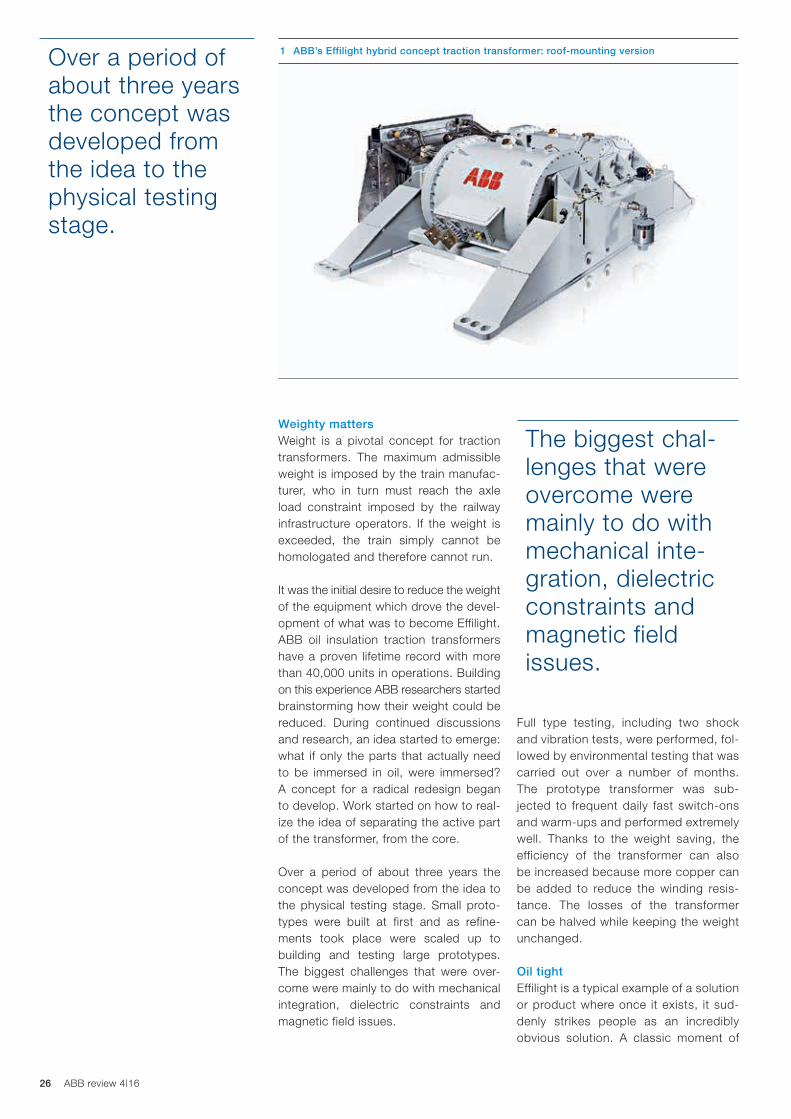
Proven technology improvedEffilight was introduced to the market at the beginning of 2016 ➔ 1 and the pub- lic launch was in September 2016 at InnoTrans ➔ Title picture. The key techno-logical differentiator between Effilight and a classic traction transformer is that in a classic transformer the active part is fully immersed in oil. This means oil volume is far from ideal and the whole assembly is penalized by the large oil tank and the
resulting constraints. However, for Effi-light, ABB developed a hybrid transform-er concept where there is a small oil tank around the winding, while the core re-mains in the air.
26 ABB review 4|16
Full type testing, including two shock and vibration tests, were performed, fol-lowed by environmental testing that was carried out over a number of months. The prototype transformer was sub-jected to frequent daily fast switch-ons and warm-ups and performed extremely well. Thanks to the weight saving, the effi ciency of the transformer can also be increased because more copper can be added to reduce the winding resis-tance. The losses of the transformer can be halved while keeping the weight unchanged.
Oil tightEffilight is a typical example of a solution or product where once it exists, it sud-denly strikes people as an incredibly obvious solution. A classic moment of
Weighty mattersWeight is a pivotal concept for traction transformers. The maximum admissible weight is imposed by the train manufac-turer, who in turn must reach the axle load constraint imposed by the railway infrastructure operators. If the weight is exceeded, the train simply cannot be homol ogated and therefore cannot run.
It was the initial desire to reduce the weight of the equipment which drove the devel-opment of what was to become Effilight. ABB oil insulation traction transformers have a proven lifetime record with more than 40,000 units in operations. Building on this experience ABB researchers started brainstorming how their weight could be reduced. During continued discussions and research, an idea started to emerge: what if only the parts that actually need to be immersed in oil, were immersed? A concept for a radical redesign began to develop. Work started on how to real-ize the idea of separating the active part of the transformer, from the core.
Over a period of about three years the concept was developed from the idea to the physical testing stage. Small proto-types were built at first and as refine-ments took place were scaled up to building and testing large prototypes. The biggest challenges that were over-come were mainly to do with mechanical integration, dielectric constraints and magnetic field issues.
Over a period of about three years the concept was developed from the idea to the physical testing stage.
The biggest chal-lenges that were overcome were mainly to do with mechanical inte-gration, dielectric constraints and magnetic field issues.
1 ABB’s Effilight hybrid concept traction transformer: roof-mounting version

27Weight loss program
in reality. A key solution to develop was, how is it possible to ensure that
the “cell” (enclo-sure of the active part) is fully sealed and immune from leaks, when the core is now exter-nal? The answer was a form of “tank in tank” con-cept, where the cell is sealed sep-arately within an-other enclosure ➔ 2.
O-ring gaskets ensure tight ness using a time proven solution.
“of course, how obvious, why did no one think of that before?”. The answer
is that, as can often be the case, the technology needed to catch up with the ideas. Once the idea of removing the core from the oil had been conceived, the challenge was how to achieve that
Now that only the windings are immersed in oil, for cooling and dielectric purpos-es, the oil volume can be reduced by up to 70 percent when compared to a classic trans-former.
Full type testing, including two shock and vibration tests, were performed, followed by environmental testing that was carried out over a num-ber of months.
3 Effilight study prototype – parameters and savings
ParametersPrototype1.1 MVA – 15 kV
Base transformer1.1 MVA – 15 kV
Savings
Total weight 3150 kg 3450 kg - 9 %
Losses (75°C) 57.2 kW 84.5 kW - 33 %
Oil weight 200 kg 573 kg - 65 %
Length 1944 m 1995 m –
Width 2500 m 2524 m –
Height 851 mm 834 mm –
2 Expanded product view of how the cell is fully sealed and protected from leaks
1 plate
1 plate
winding
Effilight tank

28 ABB review 4|16
ufacturers and easier maintenance for operators. It means that a variety of dif-ferent equipment can be fitted with the same transformer, resulting in reduced training costs by using the same trans-former across their fleet.
Maintenance and protection functions are the same for Efflilight and classic transformers, which means an existing transformer can be replaced by an Effi-light without affecting existing mainte-nance and protection systems or pro-cesses.
Future on trackToday, more than half the world’s trains are powered by ABB traction transform-ers, and most of the world’s train manu-
facturers and rail operators rely on them. Effilight is the latest member of this illus-trious family. That Effilight’s design still
Now that only the windings are im-mersed in oil, for cooling and dielectric purposes, the oil volume can be re-duced by up to 70 percent when com-pared to a classic transformer. The new approach also brings a reduction of up to 20 percent in weight. The weight sav-ing can then be reinvested in heavier windings using thicker copper wiring that improve the energy efficiency of the transformer by 50 percent, cutting elec-trical losses in half ➔ 3.
A place for everything . . .For high-power transformers, the amount of oil is not as significant as the amount of copper or steel used, which means there are high-power cases where Effi-light does not provide a significant weight reduction advantage. The full benefit of Effilight is achieved in the lower power ratings. The reason for this is the filling factor (the ratio between the weight of copper and steel versus the total trans-former weight) tends to decrease when power decreases ➔ 4– 5.
. . . and everything in its placeThe prototype has been built and tested for roof-mounting, however the Effilight traction transformer has been designed to be modular. This means that the “active part” windings and the enclosure require no redesign to adapt them for different mounting positions, be that roof mounted, underframe or in a machine room ➔ 6 – 7. Naturally this brings economies of scale and repetition advantages for train man-
The “active part” windings and the enclosure require no redesign to adapt them for different mounting positions, be that roof-mounted, underframe or in a machine room.
An existing trans-former can be replaced by an Effilight without affecting existing maintenance and protection systems or processes.
4 Weight and efficiency trade-off 5 Effilight’s benefits
5a Average weight benefit
5b Average efficiency benefit
Power 15 kV / 16.7 Hz 25 kV / 50 Hz
1.0 MVA Up to - 20 % –
2.0 MVA - 10 to - 15 % - 20 %
3.0 MVA Up to - 10 % - 15 %
4.0 MVA – Up to - 10 %
Power 15 kV / 16.7 Hz 25 kV / 50 Hz
1.0 MVA Up to + 50 % –
2.0 MVA + 20 to + 30 % Up to + 50 %
3.0 MVA Up to + 20 % + 20 to + 40 %
4.0 MVA – Up to + 20 %
2500
2700
2900
3100
3300
3500
3700
3900
4100
4300
4500
93.0 93.5 94.0 94.5 95.0 95.5 96.0 96.5 97.0
Efficiency (%) / Total losses (kW)
89.2 83.0 76.9 70.8 64.7 58.5 52.4 46.3 40.1 34.0
Tota
l wei
ght
(kg)
Standard steel tank efficient
SIC
Effilight efficient – low Ucc
Standard steel tank A-class
Effilight light
Effilight efficient

29
includes oil insulation, continues the guarantee expected from an ABB trans-former of a 40 year lifetime. Achieving substantial weight reduction through the Effilight technology allows ABB to deliver to its customers a new degree of free-dom which was not previously existing: a choice of weight reduction and energy efficiency increases. It is possible to tai-lor the solution to specific needs for spe-cific train platforms, allowing for instance the weight to be reduced by 10 percent while still increasing the efficiency by 20 to 30 percent. Effilight may currently be a young upstart, but its future looks spar-kling. Light it may be, but in terms of life-time, efficiency and delivery, a lightweight performer it is not.
Weight loss program
Toufann Chaudhuri
Marie-Azeline Faedy
Stephane Isler
ABB Sécheron SA
Geneva, Switzerland
Michelle Kiener
ABB Review
Baden-Daettwil, Switzerland
References[1] ”It’s Quicker to Travel by Train Than Plane in
Europe Right Now”, Condé Nast Traveler, 2016. [Online]. Available: http://www.cntraveler.com/stories/2016-04-11/its-quicker-to-travel-by-train-than-plane-in-europe-right-now. [Accessed: 30- Aug- 2016].
[2] M. Claessens et al., “Traction transformation: A power-electronic traction transformer (PETT)” ABB Review 1/2012, pp. 11–17.
6 Effilight is suitable for all the different assembly positions
Machine Room Roof mounted Underframe
7 Efficient traction transformers – comparing technology and application
Parameters Classic Effilight®
Lightweight variant ✓
25 kV option ✓ ✓
Wind speed cooling possible ✓
Roof mounted ✓ ✓
Machine room mounted ✓ ✓
Underfloor mounted ✓ ✓
Lifetime 40 years 40 years
30 ABB review 4|16
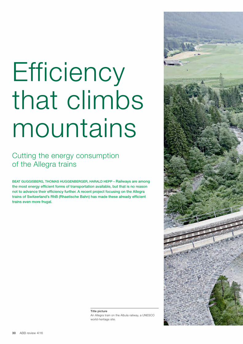
BEAT GUGGISBERG, THOMAS HUGGENBERGER, HARALD HEPP – Railways are among the most energy efficient forms of transportation available, but that is no reason not to advance their efficiency further. A recent project focusing on the Allegra trains of Switzerland’s RhB (Rhaetische Bahn) has made these already efficient trains even more frugal.
Cutting the energy consumption of the Allegra trains
Efficiency that climbs mountains
Title picture An Allegra train on the Albula railway, a UNESCO world-heritage site.

31Efficiency that climbs mountains

32 ABB review 4|16
As is often the case in engineering, the power requirements were dimensioned to meet the toughest possible condi- tions under which they were required to operate. The greatest traction power is required, for example, when moving a heavy train up a steep slope. For much of the time the units work under less demanding conditions (lighter loads, level track). Efficiency under such conditions may thus be suboptimal. A project was launched to investigate and implement ways of improving overall energy efficiency.
MotorsThe power delivered by a traction motors is the product of the magnetic flux and the torque-forming current in the stator. Both of these factors contribute to loss-es. As the current-dependent losses dominate at high power, the motor is typically oper-ated at the maxi-mum flux with the current being used to control output. However, at smaller power levels it can actually be more effi-cient to operate at a lower flux. Every speed / torque value pair has an optimum dependent on the motor parameters.
DC-linkNormally, when a traction converter var-ies its power output, this is achieved by
The railway network of RhB (Rhaetische Bahn) extends over 384 km in the Alps of south-eastern Switzerland. The rail-
way serves such popular tourist resorts as Davos, Klosters and Sankt Moritz, and carries around 10 million passengers per year. Parts of the system, featuring breathtaking sequences of twisting tun-nels and elegant viaducts, are classified as UNESCO world heritage sites ➔ title
picture. Besides RhB’s function serving tourism, the system assures local trans-portation and carries freight all year round. In some locations, where roads are regu-larly closed due to winter snowfall, the railway provides the only viable alter-native transportation.
Commencing in 2010, RhB began mod-ernizing its fleet by introducing a new family of multiple unit trains branded Allegra. These 20 trains are supplied by Stadler with compact electrical equip-ment by ABB including traction trans-formers and converters ➔ 2. The Allegra units were designed to fulfill highly de-manding requirements imposed by the tight curves, steep gradients and chal-lenging climatic conditions ➔ 1 of RhB’s network as well as the long and heavy trains they are required to pull.
maintaining the DC-link voltage as con-stant as possible and varying the output current. As the full DC-link voltage is only actually required at full power, it is viable to permit this voltage to sink to lower values when operating at lower power. Optimums were identified for different scenarios including power, tractive effort and variations in catenary voltage. These calculations did not consider the con-verter in isolation, but included losses in the transformer and motors resulting from converter switching patterns.
Disconnecting traction motorsWhen the train is required to operate at a high power output, all traction motors are required. For lower power output however, it is more efficient to selectively
use a reduced number of motors (and the associated inverters) and disconnect the others.
In view of the abundance of curves, considerations over maintaining a good dynamic behavior of the unit meant that both axles on a bogie should always exert
1 RhB provides a year-round service.
A project was launched to investigate and implement ways of improving overall energy efficiency.
© 2
016
Ed
uard
Kie
ner
33Efficiency that climbs mountains
the same tractive or brake forces. Opti-mized control is thus implemented on a bogie by bogie rather than axle by axle basis.
ImplementationThe software implementation concerned both the vehicle-level control system and the PEC (power electronic controller) that controls individual bogies and the asso-ciated traction converters.
Further to the improvement of traction energy usage, the measures taken also considered effects on the unit’s adhe-sion, and optimized this appropriately.
DC electrificationMost of the RhB system is electrified at 11 kV / 16.7 Hz. However, the 62 km line from Sankt Moritz to Tirano (Bernina line) is electrified at 1,000 V DC. Whereas some Allegra units are designed to op-erate on the AC lines only, others are equipped for dual-voltage. The measures described in this article largely concern AC operation. Improvements delivered in DC mode are more modest. Under DC operation, the DC-link voltage cannot be optimized in the manner described as it is directly fed from the catenary.
Calculations showed that a conversion of the DC section to AC would not improve the energy balance. The steeper gradi-ents of the Bernina line (up to 7 percent) mean the units are operated at full power
Beat Guggisberg
Thomas Huggenberger
Harald Hepp
ABB Discrete Automation and Motion
Turgi, Switzerland
more extensively, leaving less room for the optimization to yield real gains.
SavingsThe software changes were implement-ed and tested between September 2014 and September 2015 ➔ 3.
The implemented software modifications have led to energy savings of 950 MWh per year for all 20 units combined. This accounts for around 2 percent of the RhB’s overall electricity consumption. A tangible sign that the measures are lead-ing to greater efficiency can be seen in the observed reduction of motor temper-ature in operation.
In addition to the electricity saved, the more benign operating conditions for components and materials, including converters, motors, semiconductors and isolation should extend their operational lives and reliability.
This article is based on “Reduktion des Traktions-energiebedarfs der Allegra-Triebwagen der RhB“ by Markus Meyer, Andreas Heck, German Walch and Matthias Muri, Schweizer Eisenbahn Revue 2/16.
2 One of the Allegra trains was specially painted to mark the 125th anniversary of ABB in Switzerland.
3 The software changes were implemented between September 2014 and September 2015.
The implemented software modifica-tions have led to energy savings of 950 MWh per year.

34 ABB review 4|16

35Peak power
Title pictureCosting over $10 billion and with two parallel tubes, each of 57 km long, the Gotthard Base Tunnel relies on an intelligent and reliable electrical infrastructure to ensure safe operation.
ABB’s ZX0 medium-voltage switchgear and PMA cable protection for the Gotthard Base Tunnel
ANDREAS BEINAT, FELIX INGOLD – Launched in 1993 with preliminary geological test bores, the Gotthard Base Tunnel – the longest rail tunnel in the world – opened in June 2016, a year ahead of schedule. ABB’s contribution to this monumental construction project came in many forms – such as over 800 medium-voltage (MV) switchgear units that power the tunnel infrastructure and the many kilometers of robust PMA cable protection for the lighting system in the tunnel.
Peak power

36 ABB review 4|16
that is reliable, low-maintenance, and easy to configure and operate.
The fact that the ZX0 is gas-insulated brings with it many advantages. It offers the highest level of safety for railway employees, for example, as all live parts are completely touchproof, which means that inadvertent contact with live parts
is impossible and the switchgear can be handled safely during installation and commissioning. No gas handling is nec-essary on-site because all MV parts are inside a sealed tank, protected from ex-ternal influence, with no maintenance necessary for the parts inside the tank. This minimizes accidents and danger to human life.
The gastight enclosure protects all com-ponents against aging, thus reducing the total cost of ownership and making the ZX0 a cost-effective solution with a low overall lifetime outlay.
site in Schattdorf, Switzerland in August 2014 by representatives of both Balfour Beatty Rail and ABB.
Adapting to on-site conditionsEvery 325 m along the twin tunnels, there is a passageway between them ➔ 2. These are also designated as escape routes and every other one is equipped with electrical power. To deliver this power, ABB sup-plied ZX0 MV gas-insulated switch-gear (GIS), which had to be adapted to the difficult on-site conditions. Rail-road tunnels come with a myriad of challenges, not least of which is the fine, powdery dust abraded from the train tracks each time a train speeds over them.
ZX0 GISGiven the importance of switchgear and circuit breakers in ensuring the safe and flexible operation of the endeavor, ABB had to make sure its switchgear fitted the bill under the special conditions encountered in the tunnel complex. ZX0 GIS was the ideal solution for the Gott-hard Base Tunnel as it has a modular and compact structure that delivers and distributes energy without interruption at the highest level of availability. With the ZX0, ABB has delivered switchgear
After 20 years of construction, the world’s longest railroad tunnel opened in June 2016. In addition to increasing freight
capacity along the Rotterdam-Basel-Genoa corridor, the Gotthard Base Tun-nel also includes regular passenger ser-vices that significantly cut travel time between the north and south of Switzer-land. Up to 250 trains a day will use the tunnel when all services are running ➔ 1. It is a testament to the professional en-gineering and efficiency of those in-volved in the project that the tunnel was brought into operation a year ahead of the schedule foreseen in 2008. At that time, ABB was contracted by Balfour Beatty Rail to provide the MV switchgear needed to power the Gott-hard Base Tunnel’s infrastructure. This 50 Hz technology supplies power for systems that include air conditioning, ventilation, lighting, signaling, commu-nications and safety. Balfour Beatty Rail belongs to the Transtec consortium, which was assigned to install the rail infrastructure by the tunnel builder, Alp-Transit Gotthard AG.
ABB was able to complete this massive order in just six years. The completion of the delivery of 875 units of MV switch-gear was celebrated at the installation
ABB’s MV switchgear sup- plies power for systems that include air conditioning, ventilation, lighting, signaling, communications and safety.
1 The tunnel will carry trains only. Shown is the Faido track changeover.
Pho
to© A
lpTr
ansi
t G
otth
ard
Ltd
.

37
work can be switched off individually. For ease of use, remote access can be handled using a standard Web browser – operators can log on to the feeder ter-minal from any place at any time, with the appropriate security precautions.
The SMS feature in the new REF542plus release offers operators even more free-dom of movement. If the REF542plus registers an event, it can send a notifi-cation via text message (SMS) to the operator’s mobile phone. The operator can then log on via the Internet to the switchgear, access the REF542plus, re-motely analyze the fault and determine how to correct it.
To reduce the oc-currence of faults in a power distri-bution network, it is necessary to ana-lyze how often faults happen. For this, the REF542plus uses GPS (global positioning system) in an innovative way. Instead of using GPS as a geoloca-tion tool, the REF542plus takes advan-tage of the precise time signal provided by GPS to continuously synchronize its own embedded clock. Faults are time-stamped with a sub-millisecond preci-sion and forwarded to a central location for analysis. These time stamps help to evaluate the causes of faults.
Scope of deliveryABB has supplied more than switchgear to the Gotthard Base Tunnel. Among other things, the company also supplied the power supply and drive systems for the strongest ventilation system in the world, with a power rating of 15.6 MW. The entire ventilation control system itself – comprising activation and con-trol units for the fans and the tunnel sensors, as well as fire location detec-tion – was also supplied by ABB. A sce-nario manager provides the correspond-ing control of the airways for a variety of predefined events.
Meeting high reliability demandsAll of the tunnel equipment described above is wholly dependent upon a reli-able power supply. However, within such long and deep tunnels, exceptional climatic conditions prevail. Air tempera-tures can exceed 40 °C while regular medium-pressure washdown proce-dures contribute to a relative humidity of up to 70 percent. Moreover, excellent
Peak power
Intensive testingGiven the special challenges faced in the Gotthard Base Tunnel, steps were taken to enhance the ZX0’s integrity. For example, ABB designed the ZX0’s ac-companying local control cubicle in ac-cordance with the IP65 protection rating and also made it dust-tight and resis-tant to water jets. The design was also able to withstand the pressure varia-tions caused by passing trains.
With the inter-tunnel passageways also being used as escape routes, there were much stricter requirements for arc-fault protection and arc resistance than is the case even for restricted-ac-cess areas. The ZX0, therefore, includes a special pressure relief system to elimi-nate all risk to human safety.
Suitable monitoringTo protect, control, measure and moni-tor the network throughout the entire tunnel system, ABB provided 500 units of the REF542plus feeder terminal. The REF542plus ensures a stable, uninter-rupted energy supply by quickly locating any fault and immediately transmitting the fault type and location information to the tunnel control system.
The feeder terminal also offers remote services, providing access to stored programs and protection data via Ether-net LAN. The REF542plus can execute remote protection in a multistage way so that any faulty parts within the net-
ZX0 GIS was the ideal solution for the Gotthard Base Tunnel as it is modular and compact.
All live parts are completely touchproof, which means that inadvertent contact with live parts is impossible and the switchgear can be handled safely.
2 Inter-tunnel passageway. P
hoto
© A
lpTr
ansi
t G
otth
ard
Ltd
.
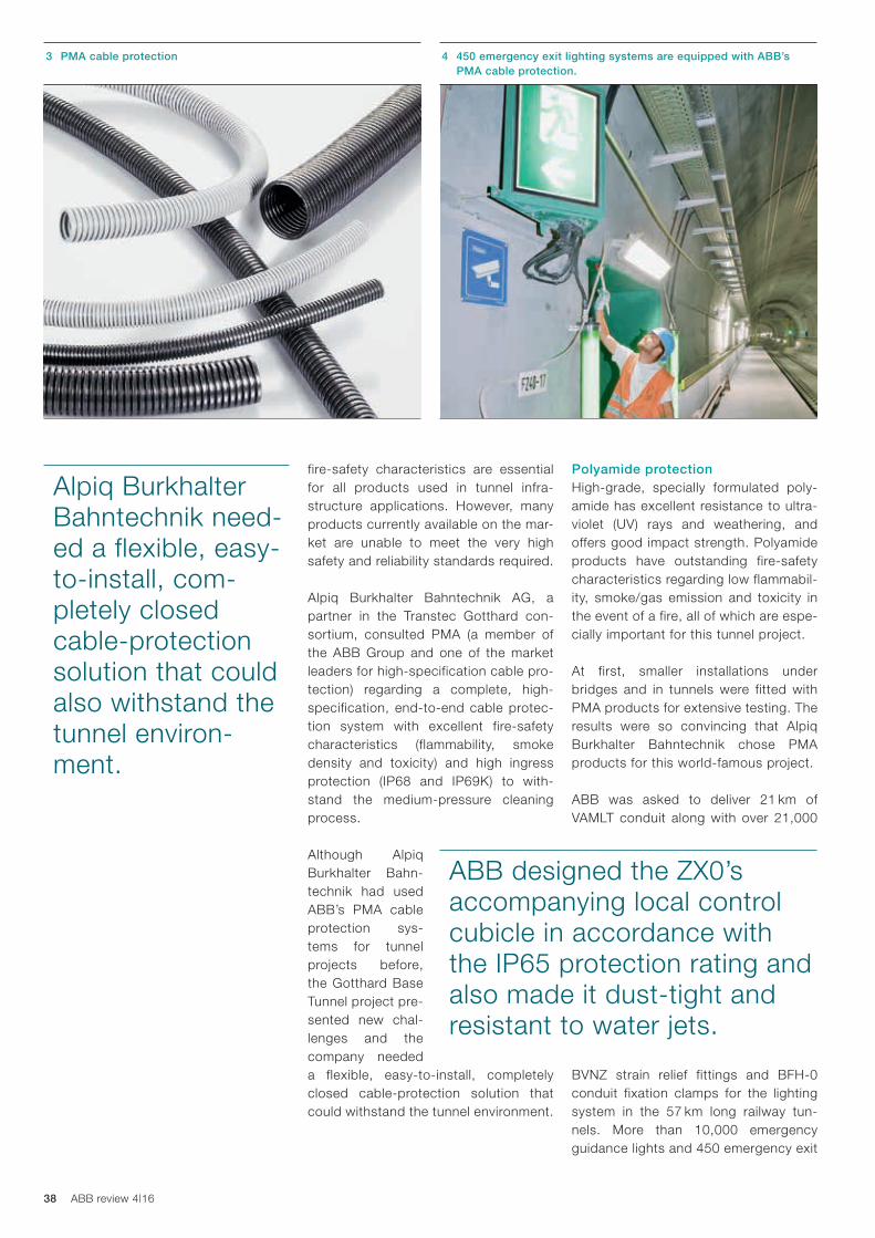
38 ABB review 4|16
Polyamide protectionHigh-grade, specially formulated poly-amide has excellent resistance to ultra-violet (UV) rays and weathering, and offers good impact strength. Polyamide products have outstanding fire-safety characteristics regarding low flammabil-ity, smoke/gas emission and toxicity in the event of a fire, all of which are espe-cially important for this tunnel project.
At first, smaller installations under bridges and in tunnels were fitted with PMA products for extensive testing. The results were so convincing that Alpiq Burkhalter Bahntechnik chose PMA products for this world-famous project.
ABB was asked to deliver 21 km of VAMLT conduit along with over 21,000
BVNZ strain relief fittings and BFH-0 conduit fixation clamps for the lighting system in the 57 km long railway tun-nels. More than 10,000 emergency guidance lights and 450 emergency exit
fire-safety characteristics are essential for all products used in tunnel infra-structure applications. However, many products currently available on the mar-ket are unable to meet the very high safety and reliability standards required.
Alpiq Burkhalter Bahntechnik AG, a partner in the Transtec Gotthard con-sortium, consulted PMA (a member of the ABB Group and one of the market leaders for high-specification cable pro-tection) regarding a complete, high-specification, end-to-end cable protec-tion system with excellent fire-safety characteristics (flammability, smoke density and toxicity) and high ingress protection (IP68 and IP69K) to with-stand the medium-pressure cleaning process.
Although Alpiq Burkhalter Bahn-technik had used ABB’s PMA cable protection sys-tems for tunnel projects before, the Gotthard Base Tunnel project pre-sented new chal-lenges and the company needed a flexible, easy-to-install, completely closed cable-protection solution that could withstand the tunnel environment.
ABB designed the ZX0’s accompanying local control cubicle in accordance with the IP65 protection rating and also made it dust-tight and resistant to water jets.
Alpiq Burkhalter Bahntechnik need-ed a flexible, easy-to-install, com-pletely closed cable-protection solution that could also withstand the tunnel environ-ment.
3 PMA cable protection 4 450 emergency exit lighting systems are equipped with ABB’s PMA cable protection.

39Peak power
PMA polyamide-based cable pro-tection systems possess high me-chanical strength combined with high flexibility. They are corrosion free with high ingress protection against water and dust.
5 BVNZ strain relief fittings and VAMLT conduits
light systems were subsequently equipped with ABB’s PMA cable protec-tion products ➔ 3–6.
A strong tunnel systemPMA polyamide-based cable protection systems possess high mechanical strength characteristics such as com-pression strength and resistance to high-energy impact, combined with high flexibility. They are corrosion free with high ingress protection against water and dust – important in the Gotthard Base Tunnel. They demonstrate high re-sistance to numerous environmental in-fluences such as chemicals (particularly cleaning agents) and UV, are immune to attack by rodents and have a broad op-erating temperature range. ABB’s PMA cable protection systems have a long lifetime and come with the assurance of dedicated customer service.
The scope of this world-renowned proj-ect presented unique technological challenges and as such represents an excellent global reference for ABB’s products.
Andreas Beinat
ABB Medium Voltage Products
Baden, Switzerland
Felix Ingold
ABB Electrification Products
Uster, Switzerland
6 Emergency light cable protection
Further readingR. Jenni et al., “Switzerland by rail: Supplying traction power for the country’s major railway initiatives,” ABB Review 2/2010, pp. 31–34.

40 ABB review 4|16
ABB to provide power, propulsion and automation for the world’s most advanced port icebreaker
ANTHONY BYATT – To make sure the maximum amount of power possible can be derived from marine engines such as those used in icebreakers, they are fitted with turbochargers. ABB has a wide range of turbocharger solutions for marine craft and are now to supply the new Power 2 800-M turbocharger for the most advanced port icebreaker ever built, which is currently in planning for construc-tion by the Vyborg Shipyard in Russia.
Record breaker
Title pictureABB’s Power2 turbocharging solution provides the power icebreakers need.

41Record breaker

42 ABB review 4|16
All these additional features mean that an icebreaker is much heavier than a normal ocean-going ship of similar size.
Moreover, due to the immense strength and often unpredictable nature of ice, icebreakers are equipped to deal with a plethora of potential dangers. For example, pressurized air and heated water jets may be forced out of the ship under the ice to help break it or ballast water may be pumped rapidly around the vessel to rock it a further assisting ice breaking.
Clearly, icebreakers have to have power-ful engines.
To make sure the maximum amount of power possible can be derived from the marine engines such as those used in icebreakers, they are fitted with tur-bochargers. ABB has a wide range of turbocharger solutions for marine craft and are now to supply turbochargers for the most advanced port icebreaker ever built, which is currently in planning for construction by the Vyborg Ship-yard in Russia. ABB will also provide the power and automation capabilities for the vessel.
The main engine will be fitted with Power2 800-M, the most advanced two-stage turbocharging system in the industry, enabling highest efficiency tur-bocharging performance.
Power2 800-MPower2 is ABB’s dedicated two-stage turbocharging system. Power2 800-M, the second generation of Power2, is the
most compact turbocharger solution of its kind. Space is at a premium in a ship’s engine room and with this in mind, ABB designed the turbocharging system to
When John Franklin searched for the North-West Pas-sage in the mid-1800s, he could scarcely have
imagined by just how much polar sea ice would retreat in the following 150 years. Now, large ocean-going ships regularly ply sea routes along the north of Canada and Russia. These shipping lanes almost halve the time it takes to voyage between the Atlantic and the Pacific oceans and the routes are remaining ice free for ever- longer periods, thus lengthening the shipping season.
With this increased shipping presence comes the increased need for icebreak-ers. Due to the nature of the job they do, icebreakers have to be of solid construc-tion: Thick ice is not often broken by ramming it, but by lifting the ship above the ice and breaking it from above. Lift-ing an icebreaker is no easy matter as icebreakers have very heavy and robust strengthening cross-members to protect the vessel against the pressure of pack ice ➔ 1. Further, an icebreaker’s hull dif-fers from a normal hull in thickness, shape and material: The bow, stern and waterline are reinforced with thick steel specially chosen for its low-temperature performance and the hull’s shape is de-signed to assist the ship to rise above the ice before falling and breaking through it.
The main engine will be fitted with Power2 800-M, the most advanced two-stage turbo-charging system in the industry.

43Record breaker
The Power2 800-M responds to the need for new marine engine technology to offer consistency of performance across con-ventional and newer marine fuel options. This application will demonstrate the ad-vances in efficiency and power density now available for four-stroke engines that operate over a wide range of load profiles and that face added demands from various bodies who regulate emis-sions. Once the icebreaker is constructed, commissioned and operating in iced-up port waters, the capabilities of the Power2 800-M will prove to be invaluable in pro-viding the power to keep waters ice-free for shipping.
take up minimal space: This two-stage turbocharging system is 20 percent more compact than conventional two-stage turbocharging solutions. Space saving is especially critical in an icebreaker as the extremely strong hull construction of the vessel leaves less internal space than would be available on an equivalent, regular ship.
The Power2 800-M’s extractable cartridge enables service to be completed in just two steps instead of the previous six, making maintenance easy and reducing downtime and service costs.
On the icebreaker’s engine, the Power2 800-M will enhance fuel efficiency and flex-ibility of operations. With up to 60 percent less NOx emissions, the Power2 800-M also substantially cuts discharges to the atmosphere – an important aspect for operation in the pure Arctic environment.
With a low-pressure and high-pressure stage, the Power2 800-M provides higher air pressure ratios – up to 12 from eight in the previous generation. A sin-gle-stage turbocharger can operate at around 65 to 70 percent efficiency; Power2 800-M exceeds 75 percent effi-ciency and is the only system currently available across the large-engine indus-try with this capability.
Anthony Byatt
External author
ABB contact for further details:
Magdalena Okopska
Power2 800-M is the most compact turbocharger of its kind.
1 Icebreakers have to have powerful engines and be of a robust construction

44 ABB review 4|16
MARIA RALPH, VERONIKA DOMOVA, PETRA BJÖRNDAL, ELINA
VARTIAINEN, GORANKA ZORIC, RICHARD WINDISCHHOFER,
CHRISHOPHER GANZ – The level of remote automation, remote monitoring, and remote control have continuously increased over the decades in key industries. Military, power utilities, nuclear, rail, port authorities, highway authorities, emergency services, mining, oil and gas, aviation, and space industries are heavy users of remote technologies and operational centers to manage their operations, fleets of assets and emergency services. This industry trend confirms what has been recently coined the 4th Industrial
Revolution by World Economic Forum founder Klaus Schwab [1] and is closely related to Zuboff’s three laws [2] which are 1) everything that can be automated will be automated, 2) everything that can be informated is infor-mated (the process of digitizing information) and 3) every digital application that can be used for monitoring and control will be used for monitoring and control. ABB is building on this operational concept to develop smarter solutions that more effectively support its remotely con-nected marine customers.
A concept for the next generation ABB customer and service portal
Improving remote marine service
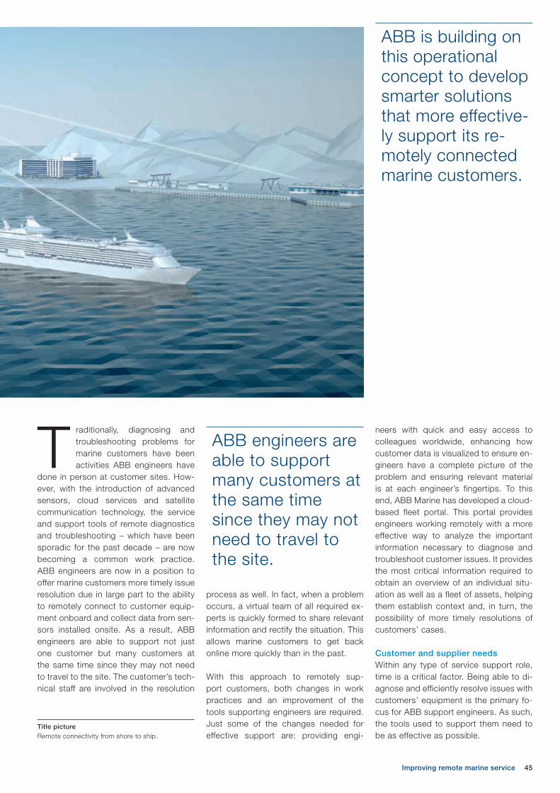
45
ABB is building on this operational concept to develop smarter solutions that more effective-ly support its re-motely connected marine customers.
ABB engineers are able to support many customers at the same time since they may not need to travel to the site.
Improving remote marine service
Title pictureRemote connectivity from shore to ship.
neers with quick and easy access to colleagues worldwide, enhancing how customer data is visualized to ensure en-gineers have a complete picture of the problem and ensuring relevant material is at each engineer’s fingertips. To this end, ABB Marine has developed a cloud-based fleet portal. This portal provides engineers working remotely with a more effective way to analyze the important information necessary to diagnose and troubleshoot customer issues. It provides the most critical information required to obtain an overview of an individual situ-ation as well as a fleet of assets, helping them establish context and, in turn, the possibility of more timely resolutions of customers’ cases.
Customer and supplier needsWithin any type of service support role, time is a critical factor. Being able to di-agnose and efficiently resolve issues with customers’ equipment is the primary fo-cus for ABB support engineers. As such, the tools used to support them need to be as effective as possible.
process as well. In fact, when a problem occurs, a virtual team of all required ex-perts is quickly formed to share relevant information and rectify the situation. This allows marine customers to get back online more quickly than in the past.
With this approach to remotely sup-port customers, both changes in work practices and an improvement of the tools supporting engineers are required. Just some of the changes needed for effective support are: providing engi-
Traditionally, diagnosing and troubleshooting problems for marine customers have been activities ABB engineers have
done in person at customer sites. How-ever, with the introduction of advanced sensors, cloud services and satellite communication technology, the service and support tools of remote diagnostics and troubleshooting – which have been sporadic for the past decade – are now becoming a common work practice. ABB engineers are now in a position to offer marine customers more timely issue resolution due in large part to the ability to remotely connect to customer equip-ment onboard and collect data from sen-sors installed onsite. As a result, ABB engineers are able to support not just one customer but many customers at the same time since they may not need to travel to the site. The customer’s tech-nical staff are involved in the resolution

46 ABB review 4|16
2) There is no easy way for technical crew members to easily and quickly transfer context information such as video or images to the remote support engineer handling the case.
3) There is also no easy way for the remote support engineer to give suggestions to the technical crew located onboard.
– Information is distributed. Not all information for diagnosing and troubleshooting a problem is in one easily accessible location. Engineers therefore spend a lot of time search-ing for relevant material.
– Locating and coordinating with a local field engineer, who is both adequately qualified and who is in close physical proximity to the customer`s vessel, to go onsite for a hardware fix can be challenging.
Designing effective support solutions re-quires an in-depth understanding of how support engineers work. Interviewing and observational approaches are used to gain valuable insights into real work practices and to assess goals, needs and concerns. In turn, this information provides the key design considerations for the creation of the new HMI (human-machine interaction) solution. The pro-totype developed took into account the following key outcomes of the interviews and observations:– Establishing the context for trouble-
shooting: 1) In order to understand all pos-
sible solutions, remote support engineers need to gather as much relevant information as possible about the problem.
1 The Dashboard tool
2 The Map tool
The customer’s technical staff are involved in the resolution process as well.

47Improving remote marine service
The tool provides reset information including locations for local support centers, port loca-tions and airports.
3 Fleet details
4 Fleet details drilled down
The Map tool provides users with an interactive map that enables users to pan and zoom as well as filter informa-tion ➔ 2. Vessel locations are shown and individual vessels are color-coded to in-dicate those vessels with issues (ie, has active alarms) in red. This enables the engineers to stay informed about the current state of all vessels they are re-sponsible for monitoring at any one time. Zooming into the vessel enables the en-gineer to see a more detailed map view with the ship’s planned route outlined. Additional information is also provided when zoomed into a specific vessel in-cluding locations for local support cen-ters (ie, where local field engineers may be available), port locations, airports, as well as a night/daytime visualization to indicate under what time of the day the vessel is operating.
Design conceptsBased on these identified needs, a new prototype of a fleet and service coordi-nation portal was developed, comprised of four main components: Dashboard, Map, Fleet details and Analytics. The prototype was developed using con-temporary web technologies such as HTML5, JavaScript, Angular JS, D3.js, bootstrap, CSS, Google Maps open API.
The Dashboard tool enables engineers to customize their view according to what information is important for them based on their role ➔ 1. The information on the dashboard can be rearranged to suit the user with information being added or deleted as they require for their work. Engineers can also filter information dis-played in this view according to a certain customer or vessel.

48 ABB review 4|16
associated with that vessel. Providing a way to effectively identify issues with customers’ vessels, as well as compe-tent support for understanding the prob-lem at hand, enables engineers to use their advanced skill set to resolve cus-tomer issues in a timely manner.
Wave problems goodbyeABB’s solution provides remote service support engineers with information in a more intuitive and easy to understand format, supporting them in their deci-sion-making. The solution further dem-onstrates ABB’s commitment to produc-ing high quality solutions targeting key domains and to improving processes for industry-leading service.
The Fleet tool provides engineers with more detailed information about the ves-sels under their watch. Vessels can be grouped (filtered or sorted) into certain categories that can be filtered further, such as vessels with active alarms. Se-lecting a vessel from this list takes the engineer to a more detailed information page about that vessel with a breakdown of data such as systems onboard, equip-ment maintenance history, planned route and spare parts onboard ➔ 3, 4.
Finally, the Analytics tool provides en-gineers with a customizable workspace whereby they can arrange the layout of information in a way that works best for them. Engineers can add or remove information, and can annotate data on-screen. This workspace can also be used to collaborate with other remote service engineers to get further assis-tance on cases. The analytics concept provides engineers with a way to dig deeper into data, using pattern matching and data tagging to find commonalities and relationships between key signals. This capability allows them to make bet-ter data comparisons and therefore more informed decisions ➔ 5.
Production management benefits The prototype developed provides re-mote service support engineers with an overall awareness of the state of the vessels they are monitoring and support-ing. Providing these engineers with the right information in an intuitive and easy to understand format enables them to more effectively and quickly understand the current vessel’s state and any issues
Maria Ralph
Veronika Domova
Petra Björndal
Elina Vartiainen
Goranka Zoric
ABB Corporate Research
Västerås, Sweden
goranka.zoric @se.abb.com
Richard Windischhofer
ABB Marine and Ports
Billingstad, Norway
Christopher Ganz
ABB Group Technology Management
Zurich, Switzerland
5 The Analytics toolBeing able to diag-nose and efficiently resolve issues with customers’ equip-ment is the primary focus for ABB sup-port engineers.
References[1] K. Schwab. (January 14, 2016). The Fourth
Industrial Revolution: what it means, how to respond [Online]. Available: https://www.weforum.org/agenda/2016/01/the-fourth-industrial-revolution-what-it-means-and-how-to-respond/
[2] In the Age of the Smart Machine: The Future of Work and Power (1988), Shoshana Zuboff

March 13-16, 2017 | George R. Brown Convention Center | Houston, Texas
Save the date and plan to join thousands of industry professionals at the premier automation and power education and technology event. Conference registration is free for ABB customers and industry professionals. For more information visit us at www.abb.com/apw
Automation & Power World 2017Connect. Collaborate. Outperform.

50 ABB review 4|16
Automation & Power World offers four days of training, networking opportunities and the chance to see firsthand the widest
range of technologies available from one company in one location ➔ 1. Together with thousands of customer attendees, ABB technical experts, industry leaders, ABB management and business partners will take a focused look at how all stake-holders can succeed together in a chang-ing business environment.
Attendees can choose from hundreds of educational workshops, daily keynotes by industry leaders, panel discussions and hands-on training courses to create a customized learning experience. Work-shops focus on topics to help achieve business goals, and are presented by technical experts, end users and indus-try specialists.
STEPHANIE JONES – Since 2009, ABB Automation & Power World has brought together professionals from the utility, industry, and transportation and infrastructure sectors for the company’s premier educational and collaboration event in North America. In 2017, the event will return to the George R. Brown Convention Center in Houston, Texas, on March 13–16.
Automation & Power World returns to Houston in March 2017
Connect. Collaborate. Outperform.
Stephanie Jones
ABB Inc.
Houston, TX, United States
1 The chance to see first-hand the widest range of technologies available from ABB in one location
The Technology & Solution Center will house the largest portfolio of ABB prod-ucts, solutions and services in North America. Visitors will have hands-on ac-cess to the latest power and automation software and technology. Plus, ABB ex-perts will be available to explain what is on display, answer questions and share their insights.
The conference also features multiple collaboration opportunities. From hosted peer-to-peer roundtable discussions to industry-specific plenary sessions to daily networking events, attendees can meet peers in their own industry as well as those with similar responsibilities in other industries to exchange information on what has worked – and what has not – when facing comparable issues.
Not only is the Automation & Power World experience priceless, so is event registration. There is no conference fee for ABB customers and other industry professionals to attend. So mark your calendars for March 13–16, 2017, and visit the event website for full event details and to register: http://new.abb.com/apw.

51Loss prophet
JANUSZ DUC, BERTRAND POULIN, MIGUEL AGUIRRE, PEDRO GUTIERREZ –
Optimization of tank shielding is a challenging aspect of design because of the need to reduce stray losses generated in the metallic parts of power transformers exposed to magnetic fields. The simulation methods now available allow the evaluation of more explorative designs that would otherwise not have been considered. FEM methodology is applied to calculate losses and temperature distribution, and several configurations of transformer shielding were considered during the research. The benefit of applying computer simulations is not only limited to cost and time savings for a single transformer unit, but also results in a better understanding of the physical processes occurring during operation. The results obtained from 3-D simulations were in close agreement with measured values. This experience, reinforced by increased trust in the applied methodology, can be applied by ABB in the design of future devices.
Predicting stray losses in power transformers and optimization of tank shielding using FEM
Loss prophet

52 ABB review 4|16
Electromagnetic simulationsFEM is a sophisticated tool widely used to solve engineering problems. It is uti-lized in new product development as well as in existing product refinement to verify a proposed design and adapt it to the client’s specifications [5]. The method re-quires the creation of a discretized model of an apparatus with adequate material properties.
Simulation software resolves basic elec-tromagnetic field distribution by solving Maxwell’s equations in a finite region of space with appropriate boundary condi-tions. Simulations described in this arti-cle were performed using a commercially available FEM software package.
Skin effectThe thickness of steel plates is much larger than the depth to which mag-netic fields will penetrate them. In order to properly represent the small penetra-tion of the magnetic field in a numerical model, a huge number of small elements must be used in the vicinity of a surface
of each component made of magnetic material. This requires computational power far exceeding the capabilities of modern workstations.
Power transformers are impor-tant components of an elec-trical network [1]. The reliable and energy-efficient operation
of transformers has a considerable eco-nomic impact on transmission and dis-tribution systems [2] and great effort is spent to make the design optimal [3].
In the case of transformers, increasing efficiency often means reducing losses. Load losses in transformers occur in conductors and magnetic parts. In wind-ings and bus bars there are two compo-nents of the losses: resistive and eddy-current. Metallic parts of transformers exposed to magnetic fields, such as the tank and core clamping structures, also produce stray losses [4].
The procedure described here is com-monly used by engineers in ABB facto-ries manufacturing large oil-immersed power transformers.
Practical solutions can be efficiently de-termined using the finite element method (FEM). The simula-tion parameters are statistically fit-ted based on doz-ens of tested units of small, medium and large power transformers pro-duced around the world by ABB. A material library dedicated to such cal-culations was developed by ABB scien-tists using laboratory measurements. The methodology gives the highest accu-racy, compared to other tools and ana-lytical methods available for stray losses estimation.
1 Simulation model of transformer (tank walls are not shown)FEM is a sophisti-cated tool widely used to solve engi-neering problems.
FEM requires the creation of a discretized model of an apparatus with adequate material properties.
Title picture 502 MVA transformer completely ready and assembled (tank, bushings, conservator and cooling system) in the test room of the ABB factory in Córdoba, Spain.

53Loss prophet
2 Magnetic shielding of the tank from HV side for the original design of investigated transformer
3 Simulation model of transformer (tank walls are shown)
Surface impedance boundary condition enables calcula-tions of stray loss-es in transformers, using a significantly reduced number of finite elements.
for this research. The results concern the unit’s stray losses and temperature dis-tribution. For simulation purposes, a sim-plified 3-D model was created including only the major components of the trans-former. The model includes a core, wind-ings, flitch plates, clamps, a tank and magnetic shields on high- (HV) and low-voltage (LV) walls ➔ 1.
Magnetic shieldingWhen loaded with full current, transformer windings produce high amounts of stray flux and losses, which translate into tem-perature rises in metallic parts. To avoid overheating, magnetic shunts are mount-ed on the tank walls ➔ 2. Shunts are fer-romagnetic laminated steel elements that guide the flux emanating from the trans-former winding ends and work as shields.
In this particular case, the tank has three embossments on the HV wall ➔ 3 to make room for the three HV bushings. Only the optimization procedure for the shunts on the HV wall is considered here because no hot spots are detected from the LV side ➔ 4.
A solution to this limitation has been imple-mented in many FEM software packages. In a first approximation, it can be stated that all eddy currents, and therefore losses, are generated close to the surface of the mag-netic conductive materials. Therefore, the phenomenon can be treated as a boundary condition rather than a volume calculation.
Surface impedance boundary conditionSurface impedance boundary condition (SIBC) is a particular case of a general approximate boundary condition relating to electromagnetic quantities at a con-ductor/dielectric interface. It enables cal-culations of stray losses in transformers, using a significantly reduced number of finite elements [6].
Surface impedance boundary conditions were assigned to magnetic and conduct-ing components of the transformer such as flitch plates, tank and clamps.
Electromagnetic simulations of power transformersA MVA three-phase 380/110/13.8 kV auto- transformer, produced by ABB, was used

54 ABB review 4|16
for bottom oil temperature, the highest value for top oil temperature). The tem-perature of the air was defined as con-stant over the tank’s height, with uniform distribution.
The highest temperatures obtained for the initial design are observed in the re-gions below the embossments in the HV wall ➔ 6. The results obtained show that these regions should be shielded as the temperature rises exceed the permis-sible limit. However, the maximum values of temperature distribution for the LV wall are acceptable ➔ 4.
Optimization of tank shieldingThe optimization of magnetic shielding was a process guided by experienced engineers. Several possible arrange-ments of the shunts were calculated in
Stray loss calculationsPreliminary calculations were carried out for a single frequency of 60 Hz, including the initial design of the shielding ➔ 2. The percentage distribution of the stray loss-es can be seen in ➔ 5. The losses generated in the tank HV wall are about 16 percent of the total stray loss-es in the construc-tional components obtained for the presented model.
Temperature distribution calculationsDuring the project, coupled magneto-thermal simulations were performed. This type of calculation is very useful for the analysis of electrical machines such as transformers and motors.
For the evaluation of component tem-perature, appropriate values of convec-tive heat transfer coefficients between components and their environment must be defined for each surface of interest in the model. A linear distribution of the oil temperature was assumed for the inter-nal surfaces of the tank (the lowest value
The highest temperatures obtained for the initial design are observed in the regions below the embossments in the HV wall.
5 Stray losses for the original design of investigated transformer
During the project, coupled magneto-thermal simulations were performed. This type of calcu-lation is very useful for the analysis of electrical machines such as transform-ers and motors. Element Relative losses [%]
Core 41.1
Clamps 19.1
Flitch plates 4.2
Tank (HV wall) 25.6 (16.2)
Shunts 10.0
Total 100.0
4 Temperature distribution for tank LV wall for the original model of investigated transformer
Shaded PlotTemperature
MAX
MIN

55Loss prophet
7 Magnetic shielding of the tank from HV side for the optimal design of investigated transformer
8 Stray losses for the optimal design of investigated transformer
The results obtained for the final design of the magnetic shielding are presented in ➔ 8 (total stray losses obtained for the original design were assumed to be 100 per-cent). Total stray losses were decreased by 11.3 percent. The highest reduction is observed in the HV wall (52 percent). The losses in the shunts themselves were also reduced by about 24 percent.
The design changes have a significant impact on the temperature obtained in the transformer tank. As illustrated in ➔ 9, the highest temperatures are located near the vertical edges of the embossments near the top of the tank. Previously ob-served hotspots were eliminated.
order to select the version that would protect the wall best, while keeping losses to a minimum. The vertical shunts
were shortened and horizontal shunts were introduced to protect regions where hotspots were predicted ➔ 7.
Element Relative losses [%]
Core 41.2
Clamps 18.9
Flitch plates 3.6
Tank (HV wall) 17.4 (7.8)
Shunts 7.6
Total 88.7
Total stray losses were decreased by 11.3 percent. The losses in the shunts them-selves were also reduced by about 24 percent.
The temperature rise test confirmed the tank tempera-tures predicted by 3-D analysis.
6 Temperature distribution for tank HV wall for the original design of investigated transformer
Shaded PlotTemperature
MAX
MIN

56 ABB review 4|16
Test resultsDuring the final acceptance tests, the load losses came out within 1 percent of the losses estimated by the internal ABB tool. Final measured stray losses (the difference between measured load losses and estimated winding losses) were 5 percent above those calculated by FEM analysis.
The temperature rise test confirmed the tank temperatures predicted by 3-D anal-ysis. No excessive gasses in the oil were reported as a result of the test, indicating no local overheating inside the tank.
Power to the simulatorElectromagnetic simulations of power transformers have proven to be a very powerful tool applicable in the develop-ment and design stages. Different al-ternative shielding solutions could be compared using FEM software and ap-propriate numerical models. Stray losses were predicted accurately, well within the uncertainty of measurements.
The applied methodology of tank shunts optimization is practical, inexpensive and easy to follow.
Magneto-thermal coupled analysis pro-vides important information on the elec-tromagnetic and thermal behavior of transformers.
To conclude, a design engineer would have probably never dared to use this shielding configuration without the in-sight obtained from 3-D simulations. Therefore, such an approach brings mul-tiple benefits in terms of the opportunity to run simulation tests of different solu-tions and result in improved designs with lower stray losses and greater efficiency.
References[1] S. Magdaleno-Adame, et al., “Hot spots
mitigation on tank wall of a power transformer using electromagnetic shields,” in Proceedings ICEM, pp. 2235–2238, 2014.
[2] J. Turowski, “Zjawiska elektrodynamiczne w ciałach ferromagnetycznych,” in Elektrodynami-ka techniczna, 3rd ed. Warszawa, Poland, pp. 375, 2014.
[3] N. Takahashi, et al., “Optimal design of tank shield model of transformer,” IEEE Transactions on Magnetics, vol. 36, no. 4, pp. 1089–1093, 2000.
[4] D. Szary, et al., “Picture perfect. Electro-magnetic simulations of transformers,” ABB Review 3/2013, pp. 39–43.
[5] K. Preis, et al., “Thermal – electromagnetic coupling in the finite-element simulation of power transformer,” IEEE Transactions on Magnetics, vol. 42, no. 4, pp. 999–1002, 2006.
[6] Y. Higuchi and M. Koizumi, “Integral equation method with surface impedance model for 3-D eddy current analysis in transformers,” IEEE Transactions on Magnetics, vol. 36, no. 4, pp. 774–779, 2000.
Janusz Duc
ABB Corporate Research
Cracow, Poland
Bertrand Poulin
ABB Transformers
Varennes, Canada
Miguel Aguirre
Pedro Gutierrez
ABB Transformers
Cordoba, Spain
Electromagnetic simulations of power transformers have proven to be a very powerful tool applicable in the development and design stages.
9 Temperature distribution for tank HV wall for the optimal model of investigated transformer
Shaded PlotTemperature
MAX
MIN
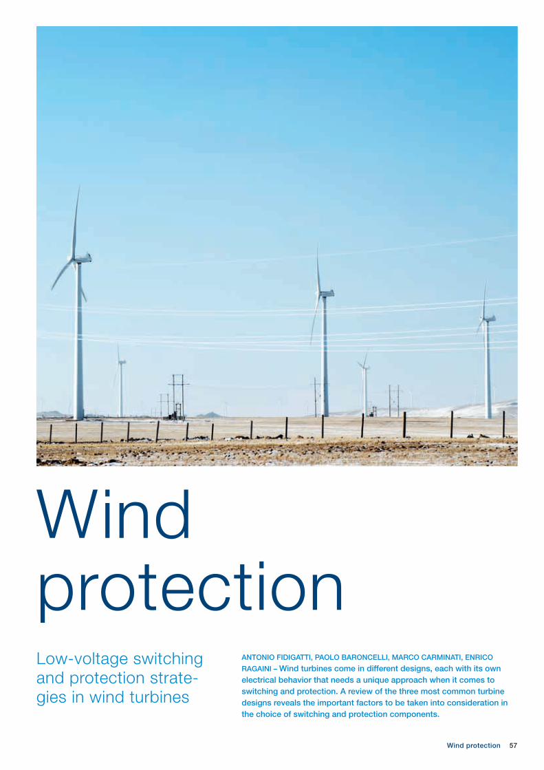
57Wind protection
ANTONIO FIDIGATTI, PAOLO BARONCELLI, MARCO CARMINATI, ENRICO
RAGAINI – Wind turbines come in different designs, each with its own electrical behavior that needs a unique approach when it comes to switching and protection. A review of the three most common turbine designs reveals the important factors to be taken into consideration in the choice of switching and protection components.
Low-voltage switching and protection strate-gies in wind turbines
Wind protection

58 ABB review 4|16
components are operating in overload conditions. The aging effects of this operational environment as well as the effects of frequent switching, salt air, humidity, pollution, etc., must be taken into account in lifetime calculations.
Compactness
Further mechanical constraints are linked to the requirements for compactness and low weight because of the limited
space available in the nacelle and the need to minimize mechanical stresses on the structure. These factors necessitate trade-offs with the overdimensioning re-quired for high efficiency and service continuity.
Faults in the nacelle
Faults in the nacelle are a particularly critical issue: The protection and control system, besides preventing and limiting the catastrophic effects of faults in the reduced space available, should ensure electrical transients do not damage the valuable mechanical system (which rep-
Power production continuity
Power production continuity requires high reliability during the entire lifetime of the wind turbine. The difficulty of physi-cal intervention makes high reliability even more desirable. A good strategy here is to use components for their main function only (eg, circuit breakers for protection, contactors for switching, etc.) rather than trying to squeeze sec-ondary functions from them. Generous tolerances are also obligatory.
Fault-disconnect
behavior
The need to guar-antee linear behav-ior even during net-work disturbances has led to the defi-nition of grid codes, compliance with which is mandato-ry. In many cases, the control of reactive power flow under standard service con-ditions as well as under disturbed condi-tions requires a high number of opera-tions by the connection devices of capacitor banks and filters.
Climatic and mechanical constraints
The environmental stresses suffered by a wind turbine can be severe: Vibrations can be of several millimeters’ amplitude and thermal conditions can range from below – 25 °C when heating and de-icing functions are switched off during inactiv-ity to + 50 °C when power-dissipating
More than 150,000 wind tur-bines are currently installed worldwide. Over 90 percent of these generate electrical
power at low voltages (≤ 1,000 V).
Challenges for wind turbine protection and controlThe electrical protection and control sys-tems that are so critical to keeping wind turbines running safely present conflict-ing requirements related to conversion efficiency, production continuity, fault disconnect, climatic and mechanical constraints, compactness and the need to reduce the effects of faults in the tight space inside the nacelle.
Conversion efficiency
Wind speed and direction can change rapidly or the wind can drop altogether so the turbine’s mechanical and electri-cal configuration must be capable of rapid adaption. This causes frequent op-eration of control actuators (eg, for pitch adjustment), which, in turn, produces re-peated connection and disconnection of the power circuit, with the attendant risk of component overheating.
Title pictureA critical factor in any wind turbine is the choice of switching and protection devices. How does turbine design influence this choice?
Protection systems must work in a wide range of electrical conditions while at the same time correctly and quickly discriminating between normal and fault conditions.
1 Simplified diagram of wind turbine with a FSIG
Low-voltage/medium-voltage
transformer
Star-delta contactors
Capacitorbattery
Connection
Gearbox
Rotorbearing
Pitch drive
Brake Asynchronousgenerator
Wind turbine control
Softstarter

59Wind protection
2 Requirements for switching/protection devices with FSIG
− An asynchronous generator directly connected to the grid: fixed-speed induction generator (FSIG)
− An asynchronous generator with its rotor excited at a variable frequency, directly connected to the grid: doubly-fed induction generator (DFIG)
− A permanent magnet synchronous (or asynchronous) generator connected to the grid through a full-scale frequency converter (FSFC)
Fixed-speed induction generatorIn the FSIG configuration, with a brush-less asynchronous generator directly connected to the grid, only very limited deviations from the synchronism speed are possible. Reactive power is, there-fore, delivered by capacitor banks, the switching of which is relatively frequent [1]. The start-up phases of the generator are managed by a softstarter equipped with parallel-connected contactors, which are closed once the steady state has been reached. Star-delta connection to the winding(s) of the generator is generally employed for the proper management of different wind regimes. Also, the genera-tor can have multiple poles to extend the working range ➔ 1–2. This electrical con-figuration is simple and highly efficient, but:– The reduced production speed range
is unsuitable for variable wind areas.− A long-time overload condition has to
be withstood, so the main circuit components have to be oversized.
− The contactor-based step control on the capacitors could produce over-voltage effects; in many such cases
resents about 80 percent of the turbine cost). This translates into several require-ments that sometimes conflict with each other, such as:− Avoid unwanted tripping but also
dangerous overvoltages.− Operate rapidly to reduce mechanical
stress and strain on the drivetrain, as well as fire risk.
− Detect the small short-circuit current contribution from the generator.
− Correctly identify the faulty feeders on the auxiliary circuits after a noncritical electrical fault in order to increase power generation availability.
− Limit the fault energy (and trip fast at low current) in order to protect weak components like the brushing system.
− Isolate faulty sections safely.− Isolate safely during maintenance,
while providing the energy required by the auxiliary systems.
The key characteristics, then, for the control and protection components are, in order of importance:− high switching reliability− reduced maintenance− compactness and reduced weight− cost
These four requirements are often in-compatible with each other and trade-off choices regarding protection and switch-ing have to be made. Optimal strategies in this trade-off can be explored by ex-amining the three main wind turbine technologies:
Main power circuit Main auxiliary circuit
Load current (A) ≤ 1,800 ≤ 320
Voltage (V) ≤ 690 ≤ 690
Frequency (Hz) 50-60 50-60
Prospective short-circuit current (kA) ≤ 35 @ 690 V
Type of load classification according to [2] ResistiveInduction motor or transformer
Presence of inrush current No Yes
Life time (years) 20 20
Number of mechanical operations with electrical isolation from the voltage sources (maintenance or out of service)
100-1,000 < 1,000
Number of generator-to-network or reconfiguration connect/disconnect mechanical operations (or electrical operations at low current)
10,000-100,000 Not applicable
Number of electrical operations< 100 (trips or emergency stop)
< 100 (trips or emergency stop)
Protection against overload and short circuit Yes Yes
Optimum solutionCircuit breaker plus contactor
Circuit breaker
A good strategy is to use compo-nents for their main function only rather than trying to squeeze secondary func-tions from them.

60 ABB review 4|16
power to support the grid. In some cas-es, star-delta connection to the genera-tor is used for the proper management of different wind regimes with rotor current values optimized in term of slip-ring and brushing system life. The advantages compared with constant speed turbines are:
− Variable-speed operation increases kilowatt-hour production.
− Utilization of a small converter, sized at up to one-third of the nominal power, allows reactive power to be supplied to the grid in normal and abnormal conditions with a good voltage and power factor control.
− Total system efficiency is high.
On the other hand, some disadvantages have to be considered:− The direct connection between the
grid and the generator transfers network perturbations to the mechan-
interaction with the softstarter could be problematic.
− The system is unable to follow fast grid perturbations without disconnection.
Therefore, this configuration is only suit-able for small- to medium-sized wind tur-bine sizes that are installed on a network with a low wind energy produc-tion penetration (< 5 percent).
Doubly-fed induction generatorThis configura-tion employs a slip-ring induc-tion generator, the rotor circuit of which is powered at a variable fre-quency ➔ 3–4. Wider variations in the ro-tation speed of the system are possible compared with the FSIG approach since the excitation frequency of the rotor al-lows displacements from the synchro-nism speed to be compensated for [1]. Generally, the excitation circuit, where power can flow in both directions (Euro-pean approach), is sized at 20 to 30 per-cent of the rating of the main circuit. The converter is used to control the genera-tor speed and power factor, allowing a wider speed range for power production as well as the ability to feed reactive
3 Simplified diagram of wind turbine with a DFIGThe aging effects of the operational environment as well as the effects of frequent switch-ing, salt air, humid-ity, pollution, etc., must be taken into account in lifetime calculations.
The protection and control system should ensure electri-cal transients do not damage the valuable mechanical sys-tem – which represents about 80 percent of the turbine cost.
Low-voltage/medium-voltage
transformer
Connection
Gearbox
Rotorbearing
Pitch drive
Brake
Asynchronousgenerator
with slip rings
Wind turbine control
Converter control
DCAC
ACDC
Start-upcircuit
Frequency converter

61
In the FSFC configuration, circuit break-ers are often employed for multiple pur-poses:− To safely disconnect and isolate for
normal operation or maintenance.− To protect: In a fault involving the
inverter or the sections between the generator and the inverter (eg, cable connection section), the circuit breaker is the only device able to detect safely the short circuit and disconnect from the power source. This requires protection releases (trip units) specifically designed for variable-frequency operation that can work in the specified environmental conditions.
− The circuit breaker provides generator disconnection redundancy.
Breaking newsA choice of switching and protection components appropriate to a particular wind turbine design is essential for smooth operation and the minimization of the effects of faults.
The protection of wind turbines and oth-er renewable generators is an area of in-tense research and development in which ABB is heavily involved. In recent years, ABB has released a series of solu-tions that protect plants with variable fre-quency in the wind, mini-hydroelectric, wave and traction power sectors – a prominent example of which is the Tmax
Wind protection
ical drive chain, reducing the ability of the system to stay connected.
− The slip-ring brush rotor is a high-maintenance weak point.
Full-scale frequency converterWith an FSFC design, rotation speed may vary over a wide range because fre-quency variations can be compensated for by a drive placed between generator and network [1]. In the full converter con-cept, the converter decouples the gen-erator and the mechanical drivetrain from the grid ➔ 5–6. All the generated power flows through the converter to the grid. The converter provides generator torque and speed control. There are three main full converter concepts: high-speed, me-dium-speed and low-speed. These use use different gearbox and generator so-lutions. The advantages of an FSFC design compared to constant-speed tur-bines are:− There is no direct electrical connec-
tion between generator and grid. This reduces mechanical shocks on the turbine during grid faults and increas-es grid code compliance.
− A full speed range is enabled with increased annual power yield.
− Full control of active power is pos-sible, with full reactive power produc-tion.
Equipment has to be compact and light because of space constraints and the need to minimize mechani-cal stresses on the structure.
© A
ndre
as V
arro
4 Requirements for switching and protection devices with DFIG
Main power circuit Main excitation circuit Start-up circuit
Load current (A) ≤ 4,000 ≤ 630 ≤ 5
Voltage (V) ≤ 1,000 ≤ 690 ≤ 690
Frequency (Hz) 50-60 50-60 50-60
Prospective short-circuit current (kA) ≤ 30 @ 1,000 V ≤ 50 @ 690 V ≤ 50 @ 690 V
Type of load classification according to [2] Resistive Induction motor Induction motor
Presence of inrush current No No Yes
Life time (years) 20 20 20
Number of mechanical operations (or electrical operations at low current) with electrical isolation from the voltage sources (maintenance or out of service)
100-1,000 < 1,000 Not applicable
Number of generator-to-network or reconfiguration connect/disconnect mechanical operations (or electrical operations at low current) with electrical isolation from the voltage sources
10,000-100,000 1,000-10,000 Not applicable
Number of electrical operations < 100 (trips or emergency stop) < 100 (trips or emergency stop) < 10,000 (excitation circuit insertion)
Protection against overload and short circuit Yes Yes Yes
Optimum solutionCircuit breaker if < 1 operation/day or circuit breaker plus contactor if more*
Circuit breaker coordinated with contactor in parallel with the start-up circuit
Circuit breaker plus contactor
* The speed of wind turbine generators is more often in the lower range than in the rated range, resulting in frequent switching on and off at typically 2,000-5,000 cycles per year (depending on wind turbine generator type), which makes contactors the best technical solution

62 ABB review 4|16
References[1] Wind Power Plants, ABB Technical Application
Paper No. 13, document number 1SDC007112G0201 in the ABB Library.
[2] Low-voltage switchgear and control gear – Part 1: General rules, IEC Standard 60947-1, 2014.
Antonio Fidigatti
Paolo Baroncelli
Marco Carminati
Enrico Ragaini
ABB Electrification Products
Bergamo, Italy
5 Simplified diagram of wind turbine with FSFC
Main power circuit on the variable-frequency side
Main power circuit on the grid side
Main auxiliary circuit
Load current (A)≤ 5,000 or n x 700-1,600
≤ 5,000 or n x 700-1,600
≤ 250
Voltage (V) ≤ 1,000 ≤ 690 ≤ 690
Frequency (Hz) 1-16, 30-80, 40-140 50-60 50-60
Prospective short-circuit current (kA) ≤ 15 @ 1,000 V* ≤ 50 @ 690 V
Type of load classification according to [2]
Resistive Resistive Induction motor
Presence of inrush current No No Yes
Life time (years) 20 20 20
Number of mechanical operations (or electrical operations at low current) with electrical isolation from the voltage sources (maintenance or out of service)
100-1,000 < 1,000 < 1,000
Number of generator-to-network or reconfiguration connect/disconnect mechanical operations (or electrical operations at low current) with electrical isolation from the voltage sources
Not available (in general, the generator remains connected to the drive)
1,000 - 100,000 (according to the control strategies)
Not applicable
Number of electrical operations< 100 (trips or emergency stop)
< 100 (trips or emergency stop)
< 100 (trips or emergency stop)
Protection against overload or short circuit
Yes Yes Yes
Optimum solution
Circuit breaker if protection is required for connection cables or inverter switch. Switch disconnector and external protection system is present.
Circuit breaker if < 1 operation/day or circuit breaker plus contactor if more
Circuit breaker
* Depending on the power and the configuration of the plant
6 Requirements for switching/protection devices with FSFC
VF and Emax VF circuit breakers that can operate in the range from 1 to 200 Hz.
The major benefits of this new range of circuit breakers for variable frequency applications are: Compatibility with all types of generators – even in overspeed conditions – thanks to the high rated voltage of the circuit breakers (up to 1,000 V); standardization of switchboard design, regardless of the end market; and optimization of stock management thanks to dual IEC/UL circuit breaker marking. This new family of trip units, to-gether with optimized current sensors, ensures high-precision protection over an extended frequency range. Whilst im-proved arcing chamber and contacts guarantee high breaking capacity over the whole frequency range, the dimen-sions are the same as standard circuit breakers.
Developments in protection and switch-ing devices are ongoing – for example, to harness the power of the Internet and the cloud to allow remote optimized power control at any time and from any-where.
This article is based on the following IEEE paper: A. Fidigatti, P. Baroncelli, M. Carminati and E. Ragaini, “Selection of low voltage switching and protection devices in wind power generators,” Industry Applica-tions Society Annual Meeting (IAS), © 2011 IEEE, Orlando, FL, 2011, pp. 1–5.
Low-voltage/medium-voltage
transformer
Gearbox
Rotorbearing Wind turbine control
DCAC
ACDC
Converter control
Frequency converter
Pitch drive
Brake
Variable frequency Constant frequency
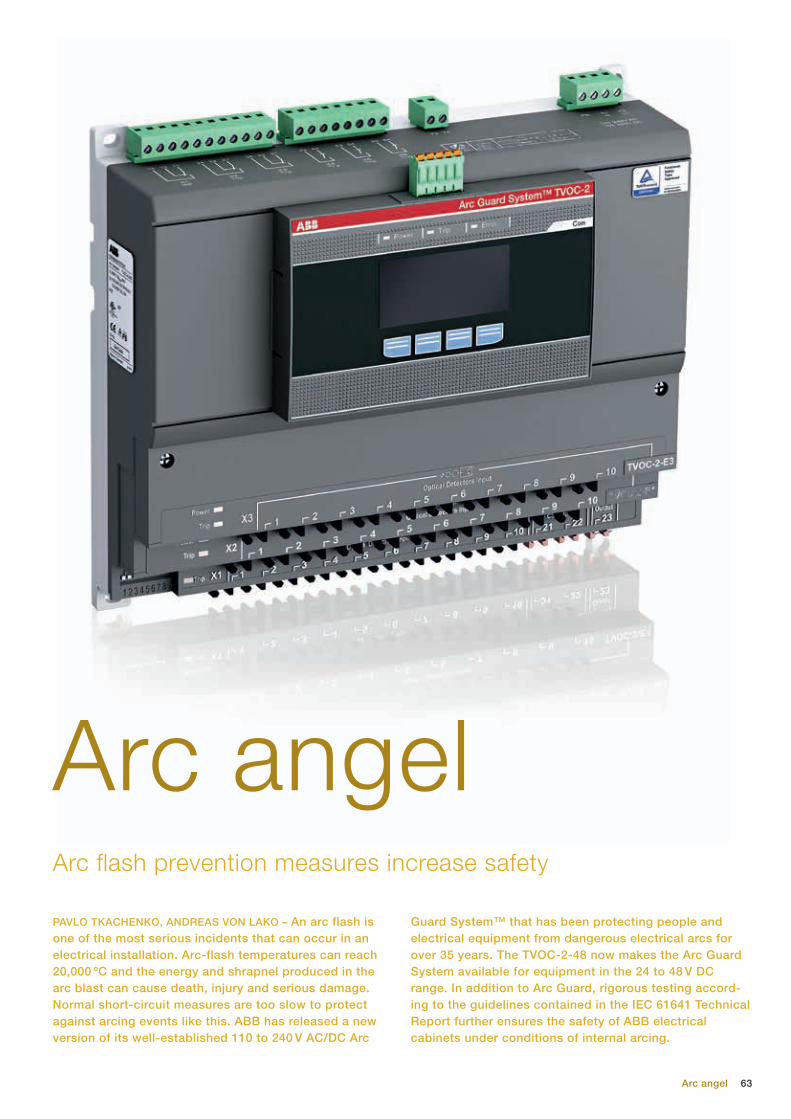
63Arc angel
PAVLO TKACHENKO, ANDREAS VON LAKO – An arc flash is one of the most serious incidents that can occur in an electrical installation. Arc-flash temperatures can reach 20,000 ºC and the energy and shrapnel produced in the arc blast can cause death, injury and serious damage. Normal short-circuit measures are too slow to protect against arcing events like this. ABB has released a new version of its well-established 110 to 240 V AC/DC Arc
Guard System™ that has been protecting people and electrical equipment from dangerous electrical arcs for over 35 years. The TVOC-2-48 now makes the Arc Guard System available for equipment in the 24 to 48 V DC range. In addition to Arc Guard, rigorous testing accord-ing to the guidelines contained in the IEC 61641 Technical Report further ensures the safety of ABB electrical cabinets under conditions of internal arcing.
Arc flash prevention measures increase safety
Arc angel

64 ABB review 4|16
ago, developed its Arc Guard System – a product that significantly reduces the damage resulting from an arcing acci-dent by quickly disconnecting the switchgear, with the help of the installed breaker, after an arcing fault. The latest ABB Arc Guard System TVOC-2-48 ex-tends the operating regime of the prod-uct from 110 to 240 V AC/DC to the 24 to 48 V DC range.
Arc Guard employs light sensors that de-tect the start of the arc flash ➔ 2. On de-tection, a signal is sent directly to the breaker trip mechanism. The total time from detection to trip signal being sent is less than 1 ms and, with a modern break-er, the entire disconnect sequence can be reduced to under 50 ms.
Fiber optic communication is used not only for its speed but also because it is immune to the EMI that may be present, especially in the event of an electrical fault. This also means that cables can be retrofitted without concern about cross-talk or electrical conductivity safety issues.
by a factor of 67,000:1 when changing from a solid to a vapor (water: 40,000:1) and the molten metal and shrapnel pro-duced by the arc can reach velocities of 1,600 km/h. An intense, high-energy ra-diation with a temperature of up to 20,000 C is produced that is capable of vaporizing nearby materials. This radia-tion can also be absorbed by metal ob-jects worn by people in the vicinity, heat-ing the objects and causing severe burns to the wearer.
A full 65 percent of switchgear arc flash incidents occur with an operator working on the equipment.
Because fatalities and serious injury are often classified as burn victims by hospi-tals, statistics on arc flash casu-alties are hard to come by. How-ever, even one arc flash incident is one too many.
In incidents that lead to arc flash, the usual meth-ods of short-cir-cuit protection is inadequate. This is because the arc itself acts as a resistor that limits the overcur-rent. This, in many cases, will lead to such a delay that by the time the load protec-tion kicks in, it is far too late ➔ 1.
Arc GuardABB has long recognized the hazards of arcing accidents and, nearly 40 years
Arc Guard employs light sensors that detect the start of the arc flash and send a signal via a fiber optic cable directly to the breaker trip mechanism.
Though rare, an arc flash is an extremely serious and dramatic event. An arc flash is the heat and light produced by an arc
caused by a fault in electrical equipment. Most arc flashes arise from human error – eg, conducting materials inadvertently left in assemblies during manufacture, in-stallation or maintenance; faults in mate-rials or workmanship; failure to put mea-sures in place to exclude the entry of small animals such as mice, snakes, etc.; use of an incorrect assembly for the application, resulting in overheating and, subsequently, an internal arcing fault; in-appropriate operating conditions; incor-rect operation; or lack of maintenance.
Arc flashes can produce earsplitting noises that surpass 160 dB; the United States OSHA (Occupational Safety and Health Administration) limit is 115 dB for a maximum of 15 mins. Copper expands
Title picture ABB’s Arc Guard System TVOC-2-48 extends arc flash protection to the 24 to 48 V DC range. Electrical cabinet safety is further enhanced by following the guidelines contained the IEC 61641 Technical Report.
1 Usual short-circuit protection methods are much too slow to prevent arcing events
Current (A)
Tim
e (s
)
> 1 s
50 - 200 ms
15 ms
Overload protection
Short-circuit protection with time delay
Instantaneous
short-circuit protection
With arc Without arc

65
of low-voltage switchgear and control-gear assemblies. The main objective of these standards is to achieve safe oper-ation under normal operating conditions as well as under abnormal operating conditions, eg, occurrence of overvolt-age, overload or short-circuit currents. However, no requirements are set out dealing with the case of an arc fault in-side the assembly.
Instead, manufacturers turn for guidance to IEC Technical Report 61641, officially titled, “Enclosed low-voltage switchgear and controlgear assemblies – Guide for testing under conditions of arcing due to internal fault.” This is not a standard, but a technical report and is not a compul-sory test. The criteria it uses to assess the protection afforded by the assembly are:1. During an arcing event, correctly
secured doors and covers do not open and remain effectively in place, and provide a minimum level of protection in accordance with the requirements of IP1X of IEC 60529.
Up to 10 light sensors can be connected to one Arc Guard System TVOC-2. Also, two extension units with additional 10 sensors each can be connected and TVOC-2 units can share current sensing information. Sensors are calibrated to have equal light sensitivity and their posi-tioning is not critical as their fish-eye lens design can observe a large angle. Over-all, the system is very easy to install.
To avoid false tripping due to camera flashes or sunlight, the arc monitor can be combined with a current sensor and set to activate only when an overcurrent is also registered.
The Arc Guard System ensures the safety of personnel even when the cabinet door is open and a functional safety SIL-2 classification makes the TVOC-2 one of the most reliable arc mitigation products available on the market.
Because they reduce downtime cost and damage, some insurance companies recommend the use of such systems and may take this into account when set-ting premiums. Also, many countries leg-islate for protection against arcing acci-dents and regulations such as The Low Voltage Directive of the European Union stipulate that measures to prevent dam-age by excessive heat, caused by arc flashes, for example, are to be taken.
System pro E powerThe IEC 61439 series of standards sets out rules and requirements for interface characteristics, service conditions, con-struction, performance and verification
ABB has long since recognized the hazards of arcing accidents and, nearly 40 years ago, developed its Arc Guard System.
Arc angel
The new ABB Arc Guard System TVOC-2-48 ex-tends the operat-ing regime of the product from 110 to 240 V AC/DC to the 24 to 48 V DC range.
2 The system can be equipped with maximum of 30 sensors per main unit

66
6. The assembly is capable of confining the arc to the defined area where it was initiated, and there is no propa-gation of the arc to other areas within the assembly. Effects of hot gases and sooting on adjacent units other than the unit under test are accept-able, as long as only cleaning is necessary.
7. After the clearing of the fault, or after isolation or disassembly of the affected functional units in the defined area, emergency operation of the remaining assembly is possible. This is verified by a dielectric test accord-ing to IEC 61439-2:2011, 10.9.2, but with a test voltage of 1.5 times the rated operational voltage for 1 min. Bending or bowing of doors and covers of the unit under test and adjacent units is acceptable providing the unit can be readily restored to a minimum level of protection in accordance with IPXXB of IEC 60529. With the exception of the tested zone as declared by the manufacturer, all other units should remain fully operable both mechanically and electrically and remain essentially in the same condition as before the test.
Personnel protection is achieved when the criteria 1 to 5, above, are fulfilled; personnel and assembly protection is achieved when criteria 1 to 6 are fulfilled; and personnel and assembly protection with limited operation capability is achieved when criteria 1 to 7 are fulfilled.
System pro E power is ABB’s main distri-bution switchboard solution. With rated current up to 6,300 A and short-circuit current up to 120 kA, System pro E pow-er complies with the test requirements IEC TR 61641. In the official language of
IEC TR 61641, ABB’s System pro E pow-er has arcing class B classification, ie, under arcing conditions, criteria 1 to 6 are fulfilled. The addition of the TVOC-2 Arc Guard allows all criteria up to and in-cluding 7 to be achieved.
Arc flashes pose a serious hazard to per-sonnel and equipment in electrical instal-lations. However, using a well-designed and well-tested switchboard solution such as the ABB System pro E power, and a fast and effective arc mitigation product such as the Arc Guard System, the danger of arc flash can be reduced to a minimum.
This criterion minimizes the risk of severe injury to persons by impact from doors, covers, etc. and ensures a minimum level of protection for persons against accidental contact with hazardous live parts.
2. No parts of the assembly are ejected that have a mass of more than 60 g except those that are dislodged and fall between the assembly and the indicators. This minimizes the risk to persons from ejecta.
3. Arcing does not cause holes to develop in the external parts of the enclosure below 2 m, at the sides declared to be accessible, as a result of burning or other effects. This mini - mizes the risk of severe injury to per - sons by direct burning from the arc.
4. The indicators do not ignite (indica-tors ignited as a result of paint or stickers burning are excluded from this assessment).
5. The protective circuit for the acces-sible part of the enclosure is still effective in accordance with IEC 61439-2.
Fiber optic communication is used not only for its speed, but also because it is immune to the EMI that may be present, especially in the event of an electrical fault.
Pavlo Tkachenko
ABB Electrification Products
Bergamo, Italy
Andreas von Lako
ABB Electrification Products
Västerås, Sweden
By using the ABB System pro E power switch-board solution and the Arc Guard System, the danger of arc flash can be reduced to a minimum.
ABB review 4|16

Mirror effect
Switching the subjectA look at recent advances in IGCT technologies for high-power electronics
UMAMAHESWARA VEMULAPATI, MUNAF RAHIMO, MARTIN ARNOLD, TOBIAS
WIKSTRÖM, JAN VOBECKY, BJÖRN BACKLUND, THOMAS STIASNY – In the mid-1990s, ABB introduced a new member of the power electronics family – the integrated-gate commutated thyristor (IGCT). Like the gate turn-off thyristor (GTO) from which it evolved, the IGCT is a fully control-lable semiconductor switch that can handle the high currents and voltages prevalent in high-power electronics applications. The IGCT has a better performance than the GTO regarding turn-off time, size, the degree of integration, power density, etc. and this superiority has helped it become the device of choice for industrial medium-voltage drives (MVDs). It has also found use in many other applications such as wind-power conversion, STATCOMs and interties. IGCT technology development has made rapid progress over the past decade.
67Switching the subject

68 ABB review 4|16
creases have come from achieving lower losses and/or higher operating tempera-tures, chiefly enabled by an increased device safe operation area (SOA) that allows higher turn-off current. Absolute power has been increased by enlarging the state-of-the-art 91 mm diameter wa-fer to 150 mm and integration concepts that provide full functionality with a single wafer device instead of employing two devices (IGCT and diode).
Increased margins: high-power technology
The main limiting factor in conventional IGCTs relates to the maximum control-lable turn-off current capability and not losses or thermal constraints. Therefore, the introduction of the high-power tech-nology (HPT) platform [2] has been hailed as a major step forward in improving IGCT
SOA performance while providing an en-abling platform for future development.
An HPT-IGCT gives an increase in the maximum turn-off current of up to 40 per-cent at 125 °C. HPT-IGCTs incorporate an advanced corrugated p-base design – compared with a standard uniform p-base junction – that ensures controlled and uniform dynamic avalanche operation with better homogeneity over the diame-ter of the wafer during device turn-off ➔ 3. The HPT has been proven for IGCT prod-ucts with voltage ratings of up to 6.5 kV. In tests, 91 mm, 4.5 kV HPT-IGCTs have turned off currents in excess of 5 kA, with-standing extreme conditions with a large stray inductance.
In many ways, an IGCT is similar to a GTO. Like the GTO, the IGCT is ba-sically a switch that is turned on and off by a gate signal. However, IGCTs
have advantages over GTOs: They can withstand higher rates of voltage rise (so no snubber circuit is needed); conduc-tion losses are lower; turn-off times are faster and more controllable; cell size on the silicon wafer is smaller; and the solid gate connection used by IGCTs results in lower inductance. Furthermore, the IGCT drive circuit is integrated into the pack-age [1] ➔ 1.
In the past couple of decades, IGCTs have become ubiquitous in high-power electronics and are now available in volt-age ratings ranging from 4.5 kV to 6.5 kV and in three main types: asymmetric, reverse-conducting (RC-IGCT) and sym-metric or reverse-blocking (RB-IGCT).− Asymmetric IGCTs cannot block
reverse voltages of more than a few tens of volts. Consequently, they are used where such a voltage would never occur – for example, in a switching power supply – or are equipped with an appropriate anti-
Title picture The invention of IGCTs has changed the rules in the power electronics landscape. Pictured is an ABB IGCT with gate unit.
The hermetic press-pack design of the IGCT has for years proven its reliability in the field.
1c The IGCT wafer in a hermetic package and with its integrated gate unit
parallel diode to conduct currents in the reverse direction. Asymmetric IGCTs have the highest power level for a given wafer size.
− RC-IGCTs have a diode integrated into the same GCT wafer to conduct currents in the reverse direction, but this uses wafer area that could otherwise be used for switching function capacity.
− Symmetrical IGCTs are inherently able to block reverse voltages, but conduct currents only in the forward direction.
The hermetic press-pack design of the IGCT has for years proven its reliability in the field with respect to power semicon-ductor device protection and load cycling capability. Consisting of a few layers of well-designed materials there are no is-sues with solder voids or bond liftoff, as is experienced by other technologies.
IGCT performance trendsIn the past ten years, IGCT technology has seen major advances, especially regarding lower conduction losses and higher power densities ➔ 2. Power in-
1 IGCT device
1a Schematic cross-section of an asymmetric IGCT
1b Top view of a 91 mm IGCT wafer
CathodeGate
Anode
p
n+ n+
n –
Cathode
p+
n

69
can be a valid option and the HPT-IGCT can be improved to accommodate this. Accordingly, the corrugated p-base dop-ing profile was further optimized to al-low a full SOA in the whole temperature range up to 140 °C. Also, the internal in-terfaces, such as the metallization on the wafer, were improved to reach a higher thermomechanical wear resistance. The verification of these improvements has started and the first results look promis-ing. Also, this so-called HPT+ technology has a clearly improved technology curve compared with HPT-IGCT due to its opti-mized corrugated p-base design [5].
Reduced conduction losses:
toward a 1 V on-state, 3.3 kV IGCT
In recent years, there has been a clear trend toward using multilevel topologies in many power electronics applications. Such products often operate at fairly low switching frequencies but at the same time require high current-carrying capa-bilities and/or high efficiency. Due to its inherent low-conduction-loss thyristor
Integration: high voltage ratings (10 kV IGCT)
It would be possible to make a three-level inverter without series connection for line voltages of 6 to 6.9 kV if IGCTs with a voltage rating in the range of 8.5 to 10 kV were available. Such a device offers simple mechanical design, less control complexity and high reliabili-ty compared with the series connection of two 4.5 or 5.5 kV devices for line volt-ages of 6 to 6.9 kV. To prove the feasibil-ity of this approach, devices rated at 10 kV have been manufactured using the HPT platform and the concept has been shown to work [4] ➔ 4.
Improved thermal performance:
high-temperature IGCT (HPT+)
One way to increase the output power of an existing converter design is to in-crease the temperature rating of the power semiconductor device used. For continuous operation, however, the cool-ing system capabilities may limit this in-crease. For intermittent high-power op-eration, though, a temperature increase
Integration: RB-IGCT
In some cases – such as with a solid-state DC breaker, in AC applications or in cur-rent source inverters (CSIs) – a symmetri-cal blocking switching device is required. Although this could be accomplished by using an asymmetric IGCT connected in series with a fast diode, the preferred solution is a symmetric IGCT in a single wafer. Since the required performance and some modes of operation are different from other IGCTs, device design optimi-zation is needed to achieve the reverse-blocking performance along with low losses and robust switching performance. Both 6.5 kV RB-IGCTs for CSI applica-tions and 2.5 kV RB-IGCTs for bi-direc-tional DC breaker applications have been developed. A 91 mm, 2.5 kV RB-IGCT, for example, has been demonstrated with an on-state voltage drop as low as 0.9 V at rated current (1 kA) at 125 °C and a maxi-mum controllable turn-off current capabil-ity up to 6.8 kA at 1.6 kV, 125 °C [3].
Switching the subject
In the past ten years, IGCT tech-nology has seen major advances, especially regard-ing lower conduc-tion losses and higher power densities.
2 IGCT development trends for achieving lower losses and/or higher power handling capabilities
3 Experimental results of the HPT-IGCT maximum controllable turn-off current capability against a standard IGCT
Max
imum
tur
n-of
f cu
rren
t (k
A)
Temperature (ºC)
3
4
5
6
7
8
0 50 100 150
p
n+
n –
CathodeGateGate
pn+
n –
HPT-IGCT
Standard IGCT
Corrugated p-base
VDC = 2,8 kV, Ls = 300 nH
4 91 mm, 10 kV IGCT and its measured turn-off waveforms at 3.3 kA, 5.5 kV and 125 °C
Volta
ge (k
V) C
urre
nt (k
A)
Time (µs)
0
1
2
3
5
6
7
4
8
0 2 4 6 8 10
Voltage
Current
Larger area Integration
Reduced losses
Increased margins(safe operation area)
Low-loss IGCT (~1 V on-state)Low-voltage IGCT (2.5 kV-3.3 kV)
Concept variants of GCT HPT/HPT+ IGCT
150 mm RC-IGCT AbsoluteIncreasing device power
Density
Improved thermalHigh-temperature IGCT
BGCTRB-IGCT
10 kV IGCT
diode
GCT

70 ABB review 4|16
first 150 mm, 4.5 kV RC-IGCT prototypes based on HPT+ technology have recent-ly been manufactured. With these devic-es, it will be possible to make three-level inverters up to about 20 MW without the need for series or parallel connection of power semiconductor devices [8] ➔ 6.
Future trend: Full integration with bi-mode gate-commutated thyristorThe conventional RC-IGCT enables better component integration in terms of pro-cess and reduced parts count at the sys-tem level, and therefore improved reli-ability. As explained above, in an RC-IGCT the GCT and diode are integrated into a single wafer, but they are fully sepa-rated from each other as shown in ➔ 2. Consequently, in the RC-IGCT, the utili-zation of the silicon area is limited in the GCT region when operating in GCT mode and in the diode region when operating in the diode mode. Therefore, a new fully integrated device concept (interdigitated integration) was developed that resulted in the bi-mode gate-commutated thyris-tor (BGCT), which integrates IGCT and diode into a single structure while utiliz-ing the same silicon volume in both GCT and diode modes [9] ➔ 7. Each segment acts either as GCT cathode or diode anode.
This interdigitated integration results not only in better usage of the diode and GCT areas but also better thermal distri-bution, softer reverse recovery and lower leakage current compared with conven-
properties and hard-switched functional-ity, the IGCT is predestined for these ap-plications. Therefore, further optimization is required to achieve very low on-state voltages (~1 V) through anode engineer-ing while maintaining good overall perfor-mance ➔ 5.
Since there is a certain amount of free-dom in selecting the device voltage for a multilevel system, a number of simu-lations and experiments have been performed for a wide range of voltage classes to see what performance can be achieved [6]. The available results are summarized in ➔ 5 and give input to the designers of multilevel converters to see how the systems can be optimized with respect to the minimum total inverter losses for a given topology, voltage rat-ing and current rating.
Furthermore, first prototype samples of 3.3 kV RC-IGCTs were manufactured to verify the simulation results. Three differ-ent anode injection trials were carried out (A1, A2 and A3) to ensure the poten-tial of 3.3 kV RC-IGCTs to achieve very low conduction losses even at higher cur-rents with reasonable switching losses [7].
Larger area: 150 mm RC-IGCT
The quest for ever-greater power ratings makes larger silicon diameters inevitable. Compared with the previous technology, HPT has an improved scalability that enables the design of devices beyond the standard 91 mm wafer size. The
Power increases have come from achieving lower losses and/or high-er operating tem-peratures, chiefly enabled by an increased device SOA that allows higher turn-off current.
5 IGCT anodic engineering
5a IGCT structure
5b IGCT doping and anode engineering carrier profiles along the section a’–a
5c Technology curves of different voltage class 91 mm IGCTs at 125 °C achieved through anode engineering
CathodeGate
n+
Cathode
n –
Anode
p
p
n+
n+
n –
p+
p+
n
n
Anode engineering
Carrier density
Cathode Anode
Con
cent
ratio
n Very slow
slow
standard
Fast
Eof
f (I)
0
5
15
10
20
25
35
30
40
VT (V)
1,0 1,1 1,2 1,3 1,4 1,5
6.5 kV IGCT @ 1.5 kA, 3.6 kV
4.5 kV IGCT @ 2.0 kA, 2.8 kV
3.3 kV IGCT @ 2.5 kA, 1.8 kV
2.5 kV IGCT @ 3.0 kA, 1.3 kV
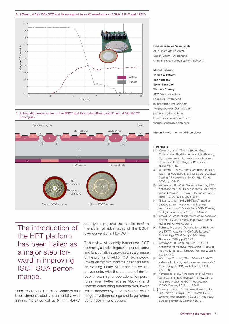
71Switching the subject
prototypes [10] and the results confirm the potential advantages of the BGCT over conventional RC-IGCT.
This review of recently introduced IGCT technologies with improved performance and functionalities provides only a glimpse of the promising field of IGCT technology. Power electronics systems designers face an exciting future of further device im-provements, with the prospect of devic-es with even higher operational tempera-tures, even better reverse blocking and reverse conducting functionalities, lower losses delivered by a 1 V on-state, a wider range of voltage ratings and larger areas up to 150 mm and beyond.
tional RC-IGCTs. The BGCT concept has been demonstrated experimentally with 38 mm, 4.5 kV as well as 91 mm, 4.5 kV
Umamaheswara Vemulapati
ABB Corporate Research
Baden-Dättwil, Switzerland
Munaf Rahimo
Tobias Wikström
Jan Vobecky
Björn Backlund
Thomas Stiasny
ABB Semiconductors
Lenzburg, Switzerland
Martin Arnold – former ABB employee
References[1] Klaka, S., et al., “The Integrated Gate
Commutated Thyristor: A new high efficiency, high power switch for series or snubberless operation,” Proceedings PCIM Europe, Nürnberg, 1997.
[2] Wikström, T., et al., “The Corrugated P-Base IGCT – a New Benchmark for Large Area SQA Scaling,” Proceedings ISPSD, Jeju, Korea, 2007, pp. 29–32.
[3] Vemulapati, U., et al., “Reverse blocking IGCT optimised for 1 kV DC bi-directional solid state circuit breaker,” IET Power Electronics, Vol. 8, Issue. 12, 2015, pp. 2308–2314.
[4] Nistor, I., et al., “10 kV HPT IGCT rated at 3200A, a new milestone in high power semiconductors,” Proceedings PCIM Europe, Stuttgart, Germany, 2010, pp. 467–471.
[5] Arnold, M., et al., “High temperature operation of HPT+ IGCTs,” Proceedings PCIM Europe, Nürnberg, Germany, 2011.
[6] Rahimo, M., et al., “Optimization of High-Volt-age IGCTs towards 1V On-State Losses,” Proceedings PCIM Europe, Nürnberg, Germany, 2013, pp. 613–620.
[7] Vemulapati, U., et al., “3.3 kV RC-IGCTs optimized for multilevel topologies,” Proceed-ings PCIM Europe, Nürnberg, Germany, 2014, pp. 362–69.
[8] Wikström, T., et al., “The 150 mm RC IGCT: a device for the highest power requirements,” Proceedings ISPSD, Waikoloa, HI, 2014, pp. 91–94.
[9] Vemulapati, et al., “The concept of Bi-mode Gate-Commutated Thyristor – a new type of reverse-conducting IGCT,” Proceedings
ISPSD, Bruges, 2012, pp. 29–32.[10] Stiasny, T., et al., “Experimental results of a
large area (91 mm) 4.5 kV ‘Bi-mode Gate Commutated Thyristor’ (BGCT),” Proc. PCIM Europe, Nürnberg, Germany, 2016.
The introduction of the HPT platform has been hailed as a major step for-ward in improving IGCT SOA perfor-mance.
6 150 mm, 4.5 kV RC-IGCT and its measured turn-off waveforms at 9.5 kA, 2.8 kV and 125 °C
Volta
ge (k
V) C
urre
nt (k
A)
0
1
2
3
5
6
7
4
8
9
10
Time (µs)
2 2 4 6 8 10
Voltage
Current
7 Schematic cross-section of the BGCT and fabricated 38 mm and 91 mm, 4.5 kV BGCT prototypes
GCTsegments
Diodesegments
38 mm, BGCT top view 91 mm, BGCT top view
Separation region
GCT cathode
GCT anode
Diode anode
Diode cathode
Gate
p ppn+
p pn+ n+ n+ n+
n
p+ n+ n+p+ p+
n –
n+ n+
Gate
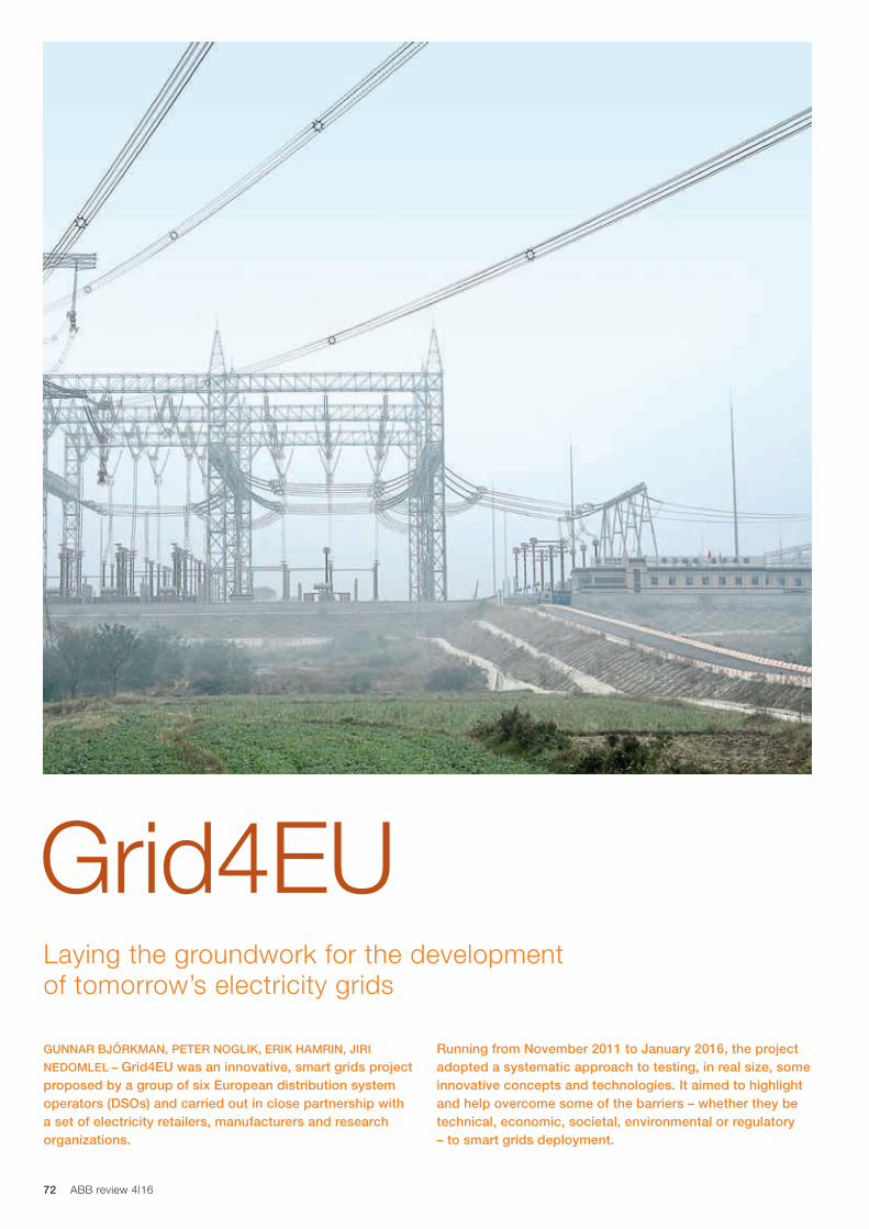
72 ABB review 4|16
Laying the groundwork for the development of tomorrow’s electricity grids
Grid4EU
GUNNAR BJÖRKMAN, PETER NOGLIK, ERIK HAMRIN, JIRI
NEDOMLEL – Grid4EU was an innovative, smart grids project proposed by a group of six European distribution system operators (DSOs) and carried out in close partnership with a set of electricity retailers, manufacturers and research organizations.
Running from November 2011 to January 2016, the project adopted a systematic approach to testing, in real size, some innovative concepts and technologies. It aimed to highlight and help overcome some of the barriers – whether they be technical, economic, societal, environmental or regulatory – to smart grids deployment.

73
with wide replication and scalability po-tential” and its ultimate goal was to test the potential for smart grids in Europe and lay the foundations for large-scale roll-out of smart grid technology.
During the project, each of the six DSOs worked with partners to evaluate the real-life performance of different smart grid tech-nologies in a variety of climates, grid topolo-gies, population densities and regulatory conditions but also to assess issues like scalability, replicability and cost benefits.
The project adopted a systemic approach to test, in real life and size, how DSOs can dynamically manage elec-tricity supply and demand. Such control is cru-cial for the inte-gration of large amounts of re-newable energy and empowers consumers to become active participants in their ener-gy choices. Ultimately, tested solutions should increase the network’s efficiency, reliability, flexibility, and resilience ➔ 1.
The project was structured to take into account the following limitations:− Existing networks consist of long-life
assets and equipment that cannot be removed or easily upgraded.
− In Europe, the technical, economical, societal and regulatory contexts for distribution grids vary significantly from country to country.
The following provides a technical descrip-tion of the three demonstrators in which ABB was involved. In addition, three other demonstrators were undertaken – under the leadership of Iberdrola, ENEL and ERDF – in which other technological aspects were implemented. In addition, the proj-ect included a number of general work packages where issues like scalability, replicability and cost benefits were inves-tigated. For more information on these,
and details of the ABB demonstrations and the general work packages, please refer to the Grid4EU website (www.grid4eu.eu) and the Grid4EU Final Report.
Demonstrator 1The principle behind Demonstrator 1 was that by increasing automation on the medium-voltage (MV) network, the grid will be able to reconfigure itself to optimize operations.
Growing penetration of renew-ables across Europe’s distri-bution grid over the past few decades has led to growing
challenges in maintaining the stability and reliability of the grid. Looking ahead, the European Commission (EC) has a goal to meet at least 40 percent of the continent’s demand for electrical power with renewables by 2030. To achieve this ambitious target, DSOs will need to make major changes to the way they run their networks.
Recognizing this, the EC brought togeth-er six major DSOs along with 21 special-ist technology firms and academic part-ners under the Grid4EU project. It was the largest smart grid project funded by the EC to date and one in which ABB played a major role as an equipment pro-vider and system developer. Grid4EU is shorthand for a “large-scale demonstra-tion of advanced smart grid solutions
The EC brought together six major DSOs along with 21 specialist technology firms and academic partners under the Grid4EU project.
Grid4EU
Title picture The Grid4EU project helped the participants better understand the challenges associated with the future evolution of the European power grid.
1 Project participants
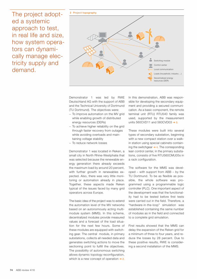
74 ABB review 4|16
In this demonstration, ABB was respon-sible for developing the secondary equip-ment and providing a secured communi-cation. As a basic component, the remote terminal unit (RTU) RTU540 family was used, supported by the measurement units 560CVD11 and 560CVD03 ➔ 3.
These modules were built into several types of secondary substation, beginning with a new compact station over a walk-in station using special cabinets contain-ing the switchgear ➔ 4. The corresponding lean control center, in the primary substa-tions, consists of five RTU560CMU05s in a rack configuration.
The software for the MMS was devel-oped – with support from ABB – by the TU Dortmund. To be as flexible as pos-sible, the whole software was pro-grammed using a programmable logic controller (PLC). One important aspect of the development was that the functional-ity had to be tested before first tests were carried out in the field. Therefore, a “hardware-in-the-loop” simulation was established containing the same number of modules as in the field and connected to a complete grid simulation.
First results showed that the MMS can delay the expansion of the Reken grid for a minimum of three to four years, and re-duce the losses by 28 percent. Due to these positive results, RWE is consider-ing a second installation of the MMS.
Demonstrator 1 was led by RWE Deutschland AG with the support of ABB and the Technical University of Dortmund (TU Dortmund). The objectives were:− To improve automation on the MV grid
while enabling growth of distributed energy resources (DERs)
− To achieve higher reliability on the grid through faster recovery from outages while avoiding overloads and main-taining voltage stability
− To reduce network losses
Demonstrator 1 was located in Reken, a small city in North Rhine-Westphalia that was selected because the renewable en-ergy generation there already exceeds the maximum load by around 20 percent, with further growth in renewables ex-pected. Also, there was very little moni-toring or automation already in place. Together, these aspects made Reken typical of the issues faced by many grid operators across Europe.
The basic idea of the project was to extend the automation level of the MV networks based on an autonomously acting multi-module system (MMS). In this scheme, decentralized modules provide measured values and a forecast of the load situa-tion for the next few hours. Some of these modules are equipped with switch-ing gear. The central module, in primary substations, collects all needed data and generates switching actions to move the sectioning point to fulfill the objectives. The possibility of autonomous switching allows dynamic topology reconfiguration, which is a new concept of operation ➔ 2.
2 Project topographyThe project adopt-ed a systemic approach to test, in real life and size, how system opera-tors can dynami-cally manage elec-tricity supply and demand.
Switching module
Control center
Local communication
Loads (household, industry ...)
Decentralized energy resources (DER)

75
Demonstrator 2The main focus of Demonstrator 2, led by Vattenfall, was to improve the moni-toring of a low-voltage (LV) network. To do this, the solution uses the ABB MicroSCADA Pro platform with the ABB DMS600 and the ABB SYS600 Historian. This software stack collects and displays data from RTUs located in secondary substations as well as from smart meters on customer premises.
Combining this information, the system can provide functionalities such as power quality reporting, outage detection, and evaluation of technical and non-technical losses. The system also has the possibil-ity to include customer meter notifica-tions in the DMS600, making it possible for operators to get instant information about incidents at customer sites. The RTUs communicate with built-in GPRS modems and use the IEC 60870-5-104 protocol to send data to the control center.
During the demonstration, over 100 sta-tions were retrofitted with ABB’s RTU cabinets. They have been designed to be robust, cheap and easy to install. In this context, “easy” means that one type of cabinet is made to fit a range of different types of substations. A range of com-pact RTU cabinets was specially de-signed as part of the project.
For an operator monitoring LV networks, it is important that all information pre-sented is meaningful and easy to grasp. In Demonstrator 2, the operators of the DSO were involved in the process of
identifying the functionality that was of highest interest to them ➔ 5. Among these functions, the outage detection function that provides data on the status of stations, groups and even the individ-ual phases of the groups in a substation, is notable ➔ 6. Functionality to compare energy billed with energy supplied and a basic framework for power quality data evaluation is also provided.
With Demonstrator 2, the partners proved that it is possible to develop and deliver cost-efficient tools for LV network moni-toring. The cost/benefit analysis per-formed by the DSO shows that the sys-tem actively helps reduce the system average interruption duration index (SAIDI) values for the DSO by 5 to 12 percent.
The findings of Demonstrator 2 will form a basis for ABB’s involvement in the up-coming smart grid project, Upgrid, and will contribute to ABB’s grid automation portfolio in Sweden.
Demonstrator 5Demonstrator 5, led by CEZ Distribuce of the Czech Republic, was designed and implemented to demonstrate the management of island operation, power quality measurement and failures on MV and LV grids. Demonstrator 5 also ex-amined the influence of electric vehicle charging on a distribution network. This was achieved mainly by the installation of remote-controlled devices, introduc-tion of infrastructure enabling fast com-munication and modifications in the SCADA (supervisory control and data
3 Standard RTU module
Grid4EU
First results showed that the MMS can delay the expansion of the Reken grid for a minimum of three to four years, and reduce the losses by 28 percent.

76 ABB review 4|16
acquisition) system to support automat-ed operation. Balancing power supply and power consumption during island operation and switching to/from island operation was performed by an auto-mated system.
Automated MV failure management mini-mizes impact on customers by using new equipment installed in distribution trans-formers (DTs), namely six units in Vrchlabí equipped with circuit breakers, RTUs and IEDs (disconnection points). Other “non-disconnection” DTs are equipped with load-break switches, RTUs and fault cur-rent indicators on MV outgoing feeders. MV-level automation required implemen-tation of communication routes and logic in the local SCADA. In total, 27 newly reconstructed DTs were equipped with components to enable Demonstration 5 functionalities.
The implemented functionality results in the smallest possible number of custom-ers being impacted by failures. Ideally, the new functionality will eliminate power out-ages completely and significantly reduce the time needed for fault localization and isolation. The reduction in time required for fault localization and isolation, accord-ing to simulation tests based on 18 months of fault data, amounted to 85 percent.
Islanding functionality was selected as a solution for areas prone to failures because of climatic or geographical conditions. Islanding was tested at the 10 kV level and, after network unifica-tion, also on the 35 kV MV network in the urban area of Vrchlabí. The power supply during island operation was pro-vided by a CHP (combined heat and power) unit of 1.56 MW capacity in-stalled within the island area. The aim of island operation was to test the capabil-ity of a predefined network to discon-nect from the surrounding MV grid in the
4 Different types of substation and the master RTU
With Demonstrator 2, the partners proved that it is possible to develop and deliver cost-efficient tools for LV network moni-toring.
4a New intelligent compact substation 4b Dedicated cabinet solution containing new switchgear and “intelligence” added to existing substation
4c Replacement of existing switchgear in a walk-in substation 4d Master RTU in the primary substation

77
case of failure on the higher voltage level and to maintain balanced opera-tion in the island. Preconditions for a successful island operation are: con-nection of sufficient power generation, adaptation of protection settings, exis-tence of a communication infrastructure and deployment of automation equip-ment. The equipment must then be able to undertake three tasks:− Disconnect the predefined (island)
area − Balance power production and
consumption in the island during the failure duration
− Reconnect the islanded area to the standard MV grid
Island operation was proven by two suc-cessful functional tests, the first of which took place in June 2014 at the 10 kV voltage level and the second in June 2015 at the 35 kV voltage level (after re-construction of the grid and voltage uni-fication within Vrchlabí).
The Grid4EU project has shown, in real-life installations, that smart grid technol-ogy is available and can function under many different grid and climatic condi-tions throughout Europe. Moreover, the project focused not only on new smart grid functionalities but also on larger-scale deployment. However, the project has also shown that many challenges around scalability, replicability and cost benefits remain to be solved. In the pan-el discussion at the final event in Paris in January 2016, the general managers
of the participating DSOs stated that “this is the time to be brave and make investments in the smart grid. The major challenges for us are the economics and the attitude of the personnel in-volved. However, these challenges will be overcome and the investments will and must start.”
The work was characterized by very good cooperation between the DSOs and the other players. This might have been one of the goals of the EC when initiating Grid4EU. For ABB, the invest-ments made in the smart grid domain and relations created within the project will bring increased business volumes. ABB has already seen follow-up orders directly connected to its participation in the project.
This work is cofunded by the European Commission under the 7th Framework Program (FP7) in the framework of the Grid4EU project (grant agreement No ENER/FP7/268206).
5 The event interface allows the operator to navigate through meter alarms and sort events
6 The DMS600 view of individual customer meters, with one event indicated by a red dot
Gunnar Björkman
Former ABB employee and
ABB Grid4EU coordinator
Peter Noglik
ABB Corporate Research
Ladenburg, Germany
Erik Hamrin
ABB Grid Automation
Västerås, Sweden
Jiri Nedomlel
ABB Grid Automation
Trutnov, Czech Republic
Grid4EU
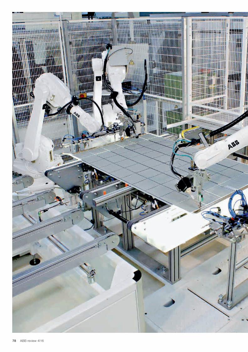
78 ABB review 4|16

79
Smart robots leverage the Internet of Things, Services and People from edge to cloud
HONGYU PEI-BREIVOLD, KRISTIAN SANDSTRÖM, LARISA RIZVANOVIC, MARKO LEHTO-
LA, SAAD AZHAR, ROGER KULLÄNG, MAGNUS LARSSON – Few doubt that, in the near future, robotics will fundamentally change production systems and dramatically increase their level of automation. To bring this transformation about, the human effort required to set up automated tasks needs to be greatly reduced. In other words, robots will have to figure out for themselves how to solve problems and adapt to dynamic environments. This step forward can be made by exploiting the Internet of Things, Services and People (IoTSP). The IoTSP facilitates the creation of new technology and novel business models that make large-scale data propagation, stream analytics and machine learning a reality.
Cloud robotics
Title pictureThe IoTSP will enable robots to be used in a much wider variety of tasks than is currently the case.
Cloud robotics
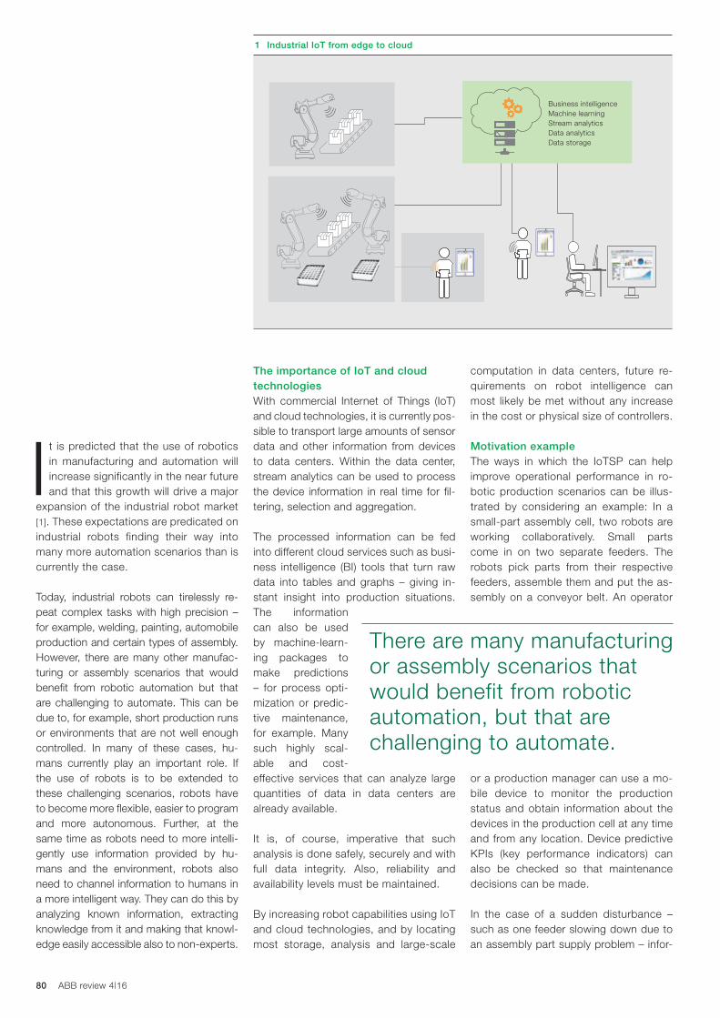
80 ABB review 4|16
It is predicted that the use of robotics in manufacturing and automation will increase significantly in the near future and that this growth will drive a major
expansion of the industrial robot market [1]. These expectations are predicated on industrial robots finding their way into many more automation scenarios than is currently the case.
Today, industrial robots can tirelessly re-peat complex tasks with high precision – for example, welding, painting, automobile production and certain types of assembly. However, there are many other manufac-turing or assembly scenarios that would benefit from robotic automation but that are challenging to automate. This can be due to, for example, short production runs or environments that are not well enough controlled. In many of these cases, hu-mans currently play an important role. If the use of robots is to be extended to these challenging scenarios, robots have to become more flexible, easier to program and more autonomous. Further, at the same time as robots need to more intelli-gently use information provided by hu-mans and the environment, robots also need to channel information to humans in a more intelligent way. They can do this by analyzing known information, extracting knowledge from it and making that knowl-edge easily accessible also to non-experts.
computation in data centers, future re-quirements on robot intelligence can most likely be met without any increase in the cost or physical size of controllers.
Motivation exampleThe ways in which the IoTSP can help improve operational performance in ro-botic production scenarios can be illus-trated by considering an example: In a small-part assembly cell, two robots are working collaboratively. Small parts come in on two separate feeders. The robots pick parts from their respective feeders, assemble them and put the as-sembly on a conveyor belt. An operator
or a production manager can use a mo-bile device to monitor the production status and obtain information about the devices in the production cell at any time and from any location. Device predictive KPIs (key performance indicators) can also be checked so that maintenance decisions can be made.
In the case of a sudden disturbance – such as one feeder slowing down due to an assembly part supply problem – infor-
The importance of IoT and cloud technologiesWith commercial Internet of Things (IoT) and cloud technologies, it is currently pos-sible to transport large amounts of sensor data and other information from devices to data centers. Within the data center, stream analytics can be used to process the device information in real time for fil-tering, selection and aggregation.
The processed information can be fed into different cloud services such as busi-ness intelligence (BI) tools that turn raw data into tables and graphs – giving in-stant insight into production situations. The information can also be used by machine-learn-ing packages to make predictions – for process opti-mization or predic-tive maintenance, for example. Many such highly scal-able and cost-effective services that can analyze large quantities of data in data centers are already available.
It is, of course, imperative that such analysis is done safely, securely and with full data integrity. Also, reliability and availability levels must be maintained.
By increasing robot capabilities using IoT and cloud technologies, and by locating most storage, analysis and large-scale
There are many manufacturing or assembly scenarios that would benefit from robotic automation, but that are challenging to automate.
1 Industrial IoT from edge to cloud
Business intelligenceMachine learningStream analyticsData analytics Data storage
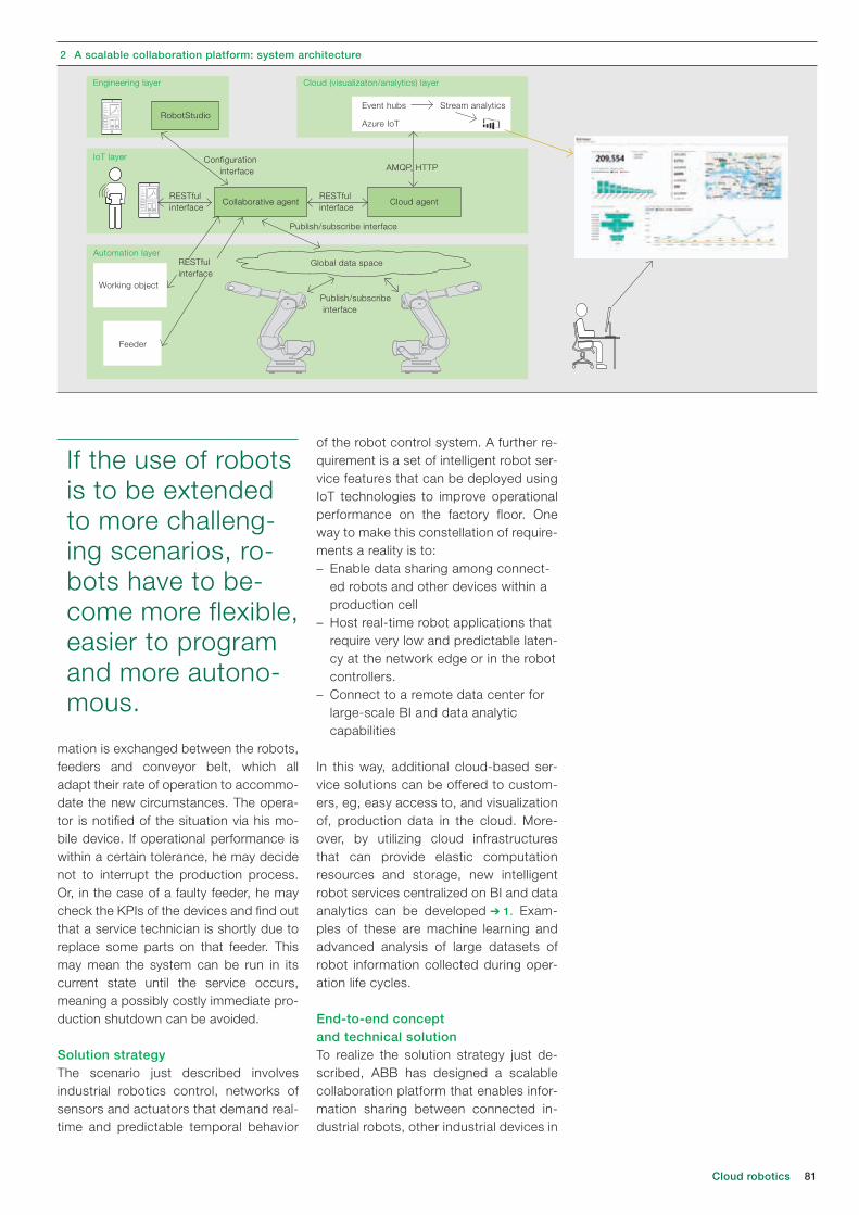
81
of the robot control system. A further re-quirement is a set of intelligent robot ser-vice features that can be deployed using IoT technologies to improve operational performance on the factory floor. One way to make this constellation of require-ments a reality is to:– Enable data sharing among connect-
ed robots and other devices within a production cell
– Host real-time robot applications that require very low and predictable laten-cy at the network edge or in the robot controllers.
– Connect to a remote data center for large-scale BI and data analytic capabilities
In this way, additional cloud-based ser-vice solutions can be offered to custom-ers, eg, easy access to, and visualization of, production data in the cloud. More-over, by utilizing cloud infrastructures that can provide elastic computation resources and storage, new intelligent robot services centralized on BI and data analytics can be developed ➔ 1. Exam-ples of these are machine learning and advanced analysis of large datasets of robot information collected during oper-ation life cycles.
End-to-end concept and technical solutionTo realize the solution strategy just de-scribed, ABB has designed a scalable collaboration platform that enables infor-mation sharing between connected in-dustrial robots, other industrial devices in
mation is exchanged between the robots, feeders and conveyor belt, which all adapt their rate of operation to accommo-date the new circumstances. The opera-tor is notified of the situation via his mo-bile device. If operational performance is within a certain tolerance, he may decide not to interrupt the production process. Or, in the case of a faulty feeder, he may check the KPIs of the devices and find out that a service technician is shortly due to replace some parts on that feeder. This may mean the system can be run in its current state until the service occurs, meaning a possibly costly immediate pro-duction shutdown can be avoided.
Solution strategyThe scenario just described involves industrial robotics control, networks of sensors and actuators that demand real-time and predictable temporal behavior
If the use of robots is to be extended to more challeng-ing scenarios, ro-bots have to be-come more flexible, easier to program and more autono-mous.
Cloud robotics
2 A scalable collaboration platform: system architecture
RobotStudio
Working object
Event hubs
Configuration interface
Publish/subscribe interface
RESTful interface
RESTful interface
Publish/subscribe interface
AMQP, HTTP
Azure IoT
Stream analytics
Feeder
Collaborative agent Cloud agent
Engineering layer
IoT layer
Automation layer
Cloud (visualizaton/analytics) layer
Global data spaceRESTfulinterface

82 ABB review 4|16
teract with robots and other devices through a lightweight RESTful interface, which is provided by a collaborative agent in the IoT layer. RESTful interfaces are based on REST (representational state transfer) – a Web architecture that takes up less bandwidth than other equivalent architectures and that simpli-fies connection of diverse clients. The collaborative agent can be deployed on any device (including the robot control-ler) on which the published/subscribe framework can be installed. The RESTful interface is also employed by the differ-
ent mobile devices that are used for pro-duction cell monitoring, as well as by a cloud agent. The cloud agent, deployed on a robot controller or some other de-vice in the production cell, uses AMQP (advanced message queuing protocol) and HTTP as an interface to send data to or interact with the cloud layer.
The proposed cloud layer in the architec-ture enables increased service opportu-nities by connecting the devices in the production cell, or the production cell itself, to the cloud. For this particular robot collaboration platform, Microsoft Azure IoT Suite [2] is used, which offers a broad range of capabilities – eg, data
a production cell and people ➔ 2. The platform, when it becomes a final prod-uct, will offer ease of use with respect to configuration, eg, discovery of robots, connecting robots for collaboration and service provision ➔ 3.
In the platform’s automation layer, real-time data exchange between robots is enabled through publish-subscribe middleware technology, eg, the data distribution service (DDS) framework. One device publishes information on a topic and other interested devices can subscribe to receive it. Sub-scriber devices do not need to know where in-formation comes from as con-text data is also provided to tell the subscriber devices what to do with the information.
The devices exchange information through a virtual global data space. The robots and the feeder mentioned in the example above could, for instance, ex-change information (current position, speed, etc.) through this global data space.
Not all devices in a production cell may be suitable for participation in a publish/subscribe framework. This can be due to, for example, accessibility limitations of third-party devices or finite computing power. Such devices can, however, in-
IoTSP is providing a new way of realizing business agility and a faster pace of innovation.
3 The platform makes it easy to configure robotic setupsUsing IoT technol-ogy to connect things, services and people will change the everyday life of users and enable intelligent industrial operations.

83
smart tags that allow, via wireless com-munication, the transmission of certain types of information – for example, CAD drawings, item description and handling instructions – to robots and operators. The dissemination of such information could, for example, allow the adjustment
of robot grasp planning with the available grippers when there are changes in the types of small parts. At present, this is an offline and manual task.
The key idea of IoTSP is to obtain infor-mation about devices and the environ-ment, analyze data from the physical and virtual world for optimized operations, and provide enhanced services to users. By delivering new end-customer soft-ware services and experiences that are based on information extracted from multiple connected devices, IoTSP is providing a new way of realizing business agility and a faster pace of innovation.
collection from devices, stream analyt-ics, machine learning, storage and data presentation. In particular, ABB has ex-ploited Azure IoT Suite to provide a pro-duction data visualization and monitoring service. The solution consists of an IoT client, an event hub (which acts as an event ingester), stream analyt-ics and Power BI (a self-ser-vice BI solu-tion). The cloud agent sends robot data to the event hub. The stream analytics ser-vice consumes that data and enables stream processing logic (in a simple SQL-like language) to be run. The results of this processing are sent to Power BI, which carries out the monitoring and visu alization of the production data.
In the engineering layer, two types of ap-plications are distinguished: Web-based simplified configuration applications and RobotStudio-based applications for ad-vanced configuration of the robots and the rest of the production.
Grasping the futureUsing IoT technology to connect things, services and people will change the ev-eryday life of users and enable intelligent industrial operations. Imagine that the small parts in the example scenario de-scribed earlier have attached to them
By using IoT and cloud technolo-gies, future requirements on robot intelligence can most likely be met without any increase in the cost or physical size of controllers.
The proposed cloud layer in the archi-tecture enables increased service oppor-tunities by connecting the devices in the production cell, or the production cell itself, to the cloud.
Cloud robotics
References[1] Modern Materials Handling staff, Industrial
robotics market expected to reach $41 billion By 2020, Available: http://www.mmh.com/article/industrial_robotics_market_expected_to_reach_41_billion_by_20202
[2] Microsoft Azure IoT Suite, https://www.microsoft.com/en-us/server-cloud/internet-of-things/azure-iot-suite.aspx
Hongyu Pei-Breivold
Kristian Sandström
Larisa Rizvanovic
Marko Lehtola
Saad Azhar
ABB Corporate Research
Västerås, Sweden
Roger Kulläng
Magnus Larsson
ABB Robotics
Västerås, Sweden

84 ABB review 4|16
CRAIG BLIZARD, ZOHEIR RABIA – Photovoltaic-diesel (PVD) hybrid solu-tions represent a key market segment that is discernibly influenced by the reduction in the manufacturing costs of the photovoltaics (PVs). In response to recent PV module price drops and diesel price increases over time, PV diesel hybrid solutions are beginning to gain acceptance around the world as an economically attractive alternative to grid extension and mini-grid systems that operate solely on diesel.
Microgrids with renewable power integration
A combined future

85A combined future
Title pictureABB’s photovoltaic-diesel hybrid system is ideal for reliable power generation in remote geographic locations.
The high cost of and strong re-liance on diesel fuel in coun-tries belonging to Sub-Saha-ran Africa, Latin America and
Southeast Asia, as well as their geo-graphic remoteness, insular distribution and topography are key factors that make PVD solutions ideal for customers in these locations.
The ABB PVD solution, which includes the PVD automation and solar inverters, can be setup as an additional source of energy in these locations thereby maxi-mizing fuel savings and reducing running time costs. The current low prices of PV systems are an added bonus that result in a quick return on investment.
The PVD energy solution provides cus-tomers with a compelling alternative to the sole use of diesel-powered mini-
grids. Worldwide there are tens of giga-watts (GW) worth of power in isolated diesel-based microgrids that would lend themselves to be retrofitted through the integration of renewable energy tech-nologies such as the PVD. This existing
diesel mini-grid market represents an enormous economic potential for years to come.
MicrogridsMicrogrids refer to distributed energy resources and loads that can be oper-ated in a controlled, coordinated way
either connected to the main power grid or in “island” mode where they neither draw power from the main grid nor sup-ply power to it. Microgrids are a gen-eral classification of small, self-sufficient power networks that serve consumers.
The microgrid con-cept is not new and yet its com-mercial signifi-cance today is only now becoming ap-parent. During the age of industrial-ization, centralized grids that served a large number of consumers from a
single primary power source made more economic sense than did microgrids. It was not feasible for most municipali-ties, colleges, or other such entities to build and manage their own small power plants and distribution networks. Micro-grids weren’t a cost-effective solution for everyday energy needs. Reliance on
Using the knowledge and benefits of the microgrid plus system, PVD 1.0 has been designed with a focus on cost effectiveness as well as engineering simplicity.
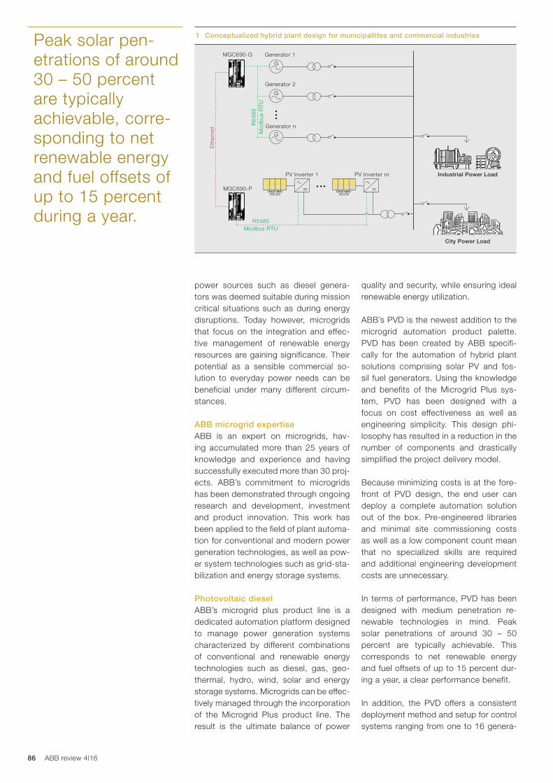
86 ABB review 4|16
quality and security, while ensuring ideal renewable energy utilization.
ABB’s PVD is the newest addition to the microgrid automation product palette. PVD has been created by ABB specifi-cally for the automation of hybrid plant solutions comprising solar PV and fos-sil fuel generators. Using the knowledge and benefits of the Microgrid Plus sys-tem, PVD has been designed with a focus on cost effectiveness as well as engineering simplicity. This design phi-losophy has resulted in a reduction in the number of components and drastically simplified the project delivery model.
Because minimizing costs is at the fore-front of PVD design, the end user can deploy a complete automation solution out of the box. Pre-engineered libraries and minimal site commissioning costs as well as a low component count mean that no specialized skills are required and additional engineering development costs are unnecessary.
In terms of performance, PVD has been designed with medium penetration re-newable technologies in mind. Peak solar penetrations of around 30 – 50 percent are typically achievable. This corresponds to net renewable energy and fuel offsets of up to 15 percent dur-ing a year, a clear performance benefit.
In addition, the PVD offers a consistent deployment method and setup for control systems ranging from one to 16 genera-
power sources such as diesel genera-tors was deemed suitable during mission critical situations such as during energy disruptions. Today however, microgrids that focus on the integration and effec-tive management of renewable energy resources are gaining significance. Their potential as a sensible commercial so-lution to everyday power needs can be beneficial under many different circum-stances.
ABB microgrid expertiseABB is an expert on microgrids, hav-ing accumulated more than 25 years of knowledge and experience and having successfully executed more than 30 proj-ects. ABB’s commitment to microgrids has been demonstrated through ongoing research and development, investment and product innovation. This work has been applied to the field of plant automa-tion for conventional and modern power generation technologies, as well as pow-er system technologies such as grid-sta-bilization and energy storage systems.
Photovoltaic dieselABB’s microgrid plus product line is a dedicated automation platform designed to manage power generation systems characterized by different combinations of conventional and renewable energy technologies such as diesel, gas, geo-thermal, hydro, wind, solar and energy storage systems. Microgrids can be effec-tively managed through the incorporation of the Microgrid Plus product line. The result is the ultimate balance of power
Peak solar pen-etrations of around 30 – 50 percent are typically achievable, corre-sponding to net renewable energy and fuel offsets of up to 15 percent during a year.
1 Conceptualized hybrid plant design for municipallites and commercial industries
Generator 1
G
Generator 2
G
Generator nG
MGC690-G
MGC690-P
Eth
erne
t
PV Inverter 1 PV Inverter m
R5485Modbus RTU
R54
85M
odb
us R
TU
Industrial Power Load
City Power Load
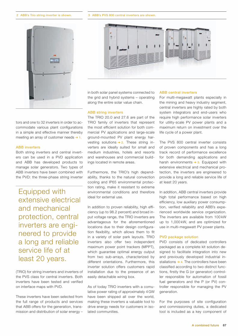
87
ABB central invertersFor multi-megawatt plants especially in the mining and heavy industry segment, central inverters are highly rated by both system integrators and end-users who require high performance solar inverters for utility-scale PV power plants and a maximum return on investment over the life cycle of a power plant.
The PVS 800 central inverter consists of proven components and has a long track record of performance excellence for both demanding applications and harsh environments ➔ 3. Equipped with extensive electrical and mechanical pro-tection, the inverters are engineered to provide a long and reliable service life of at least 20 years.
In addition, ABB central inverters provide high total performance based on high efficiency, low auxiliary power consump-tion, verified reliability and ABB’s expe-rienced worldwide service organization. The inverters are available from 100 kW up to 1,000 kW, and are optimized for use in multi-megawatt PV power plants.
PVD package solutionPVD consists of dedicated controllers packaged as a complete kit solution de-signed to facilitate integration into new and previously developed industrial in-stallations ➔ 4. The controllers have been classified according to two distinct func-tions, firstly the G (or generator) control-ler responsible for automation of fossil fuel generators and the P (or PV) con-troller responsible for managing the PV generation.
For the purposes of site configuration and commissioning duties, a dedicated tool is included as a key component of
A combined future
in both solar panel systems connected to the grid and hybrid systems – operating along the entire solar value chain.
ABB string invertersThe TRIO 20.0 and 27.6 are part of the TRIO family of inverters that represent the most efficient solution for both com-mercial PV applications and large-scale ground-mounted PV plant energy har-vesting solutions ➔ 2. These string in-verters are ideally suited for small and medium industries, hotels and resorts and warehouses and commercial build-ings located in remote areas.
Furthermore, the TRIO’s high depend-ability, thanks to the natural convection cooling and IP65 environmental protec-tion rating, make it resistant to extreme environmental conditions and therefore ideal for external use.
In addition to proven reliability, high effi-ciency (up to 98.2 percent) and broad in-put voltage range, the TRIO inverters are advantageous for the aforementioned locations due to their design configura-tion flexibility, which allows them to fit in a variety of solar park layouts. TRIO inverters also offer two independent maximum power point trackers (MPPT), which guarantee optimal energy output from two sub-arrays, characterized by different orientations. Furthermore, this inverter solution offers customers rapid installation due to the presence of an easily detachable wiring box.
As of today TRIO inverters with a comu-lative power rating of approximately 4 GW have been shipped all over the world, making these inverters a valuable tool to drive energy needs for customers in iso-lated communities.
tors and one to 32 inverters in order to ac-commodate various plant configurations in a simple and effective manner thereby meeting an array of customer needs ➔ 1.
ABB inverters Both string inverters and central invert-ers can be used in a PVD application and ABB has developed products to manage solar generators. Two types of ABB inverters have been combined with the PVD: the three-phase string inverter
(TRIO) for string inverters and inverters of the PVS class for central inverters. Both inverters have been tested and verified on interface maps with PVD.
These inverters have been selected from the full range of products and services that ABB offers for the generation, trans-mission and distribution of solar energy –
Equipped with extensive electrical and mechanical protection, central inverters are engi-neered to provide a long and reliable service life of at least 20 years.
3 ABB’s PVS 800 central inverters are shown.2 ABB’s Trio string inverter is shown.

88 ABB review 4|16
ABB’s PVD solution with the PVD con-troller and choice of string or central so-lar inverters provides a reliable, efficient and cost-effective alternative to mini-grids and grid extensions that operate solely on fossil fuels. The engineered design and flexibility of configuration make these two different power solution products highly suitable for small to mid-size industries, geographically isolated areas or in utility-scale power plants. The MGC690 and the PVD provide consum-ers with the benefits of rapid, accurate and uninterrupted control of their mi-crogrid systems enabling a stable and reliable power supply. This in combina-tion with the low price of photovoltaics, fuel savings and low running time costs of implementing a PVD solution lead to a quick return on investment and value for customers.
The MGC690 controller’s industrial grade embedded system architecture allows the PVD solution to execute the entire plant automation logic rapidly, in under 100 ms. The low power consumption coupled with the extended operating temperature range enables the MGC690 to be installed in sealed enclosures with-out the need for fans, louvers, air filters or other forced cooling equipment. This eliminates maintenance requirements associated with cooling systems and significantly reduces operating costs as-sociated with control system equipment, which is particularly advantageous for microgrid customers.
the package ➔ 5. The tool allows the user to carry out basic functions such as set-ting parameters and making controller mode changes. In addition, the user can implement high-level, real-time system status checks and view key performance indicators, without the need to install a dedicated Supervisory Control and Data Acquisition (SCADA) package. Nonethe-less if the customer requires a SCADA system, the PVD can be easily tailored with a SCADA solution to the customer’s needs.
At its core, the PVD solution utilizes MGC690 controllers, which consist of control hardware and software designed to be robust and reliable and to meet the stringent requirements of total plant au-tomation. Microgrid systems based on MGC690 feature high-density DIN-rail packaging, a flexible system architec-ture, high performance, real-time control, and fast Ethernet-based network com-munications.
To facilitate device-to-device commu-nications within PVD, messages be-tween the generator and PV controllers are transmitted via a dedicated 100 MB Ethernet connection. This configuration alleviates the need to interact with or in-terrupt existing site communication infra-structure. Downstream communications between the controllers and the field are serviced by dedicated Modbus RTU links pre-terminated into the controller.
Craig Blizard
ABB Power Grids and Grid Automation
Product Group Microgrids & Distributed Generation,
Business Unit
Genova, Italy
Zoheir Rabia
ABB Discrete Automation and Motion
Terranuova Bracciolini, Italy
4 ABB’s control system network is a complete automation solution. 5 Packaged key components ensure optimal automation.
ABB’s PVD system utilizes MGC690 controllers, which consist of control hardware and soft-ware designed to be robust and reli-able and meet the stringent require-ments of total plant automation.
PV diesel configuration tool
Ethernet network
MGC690-G MGC690-P RS 485 network AModbus RTU
RS 485 network BModbus RTU
Solar invertersGenerator controllers
RS 485 networkModbus RTU
3rd party generatorController N
3rd party generatorController 2
3rd party generatorController 1
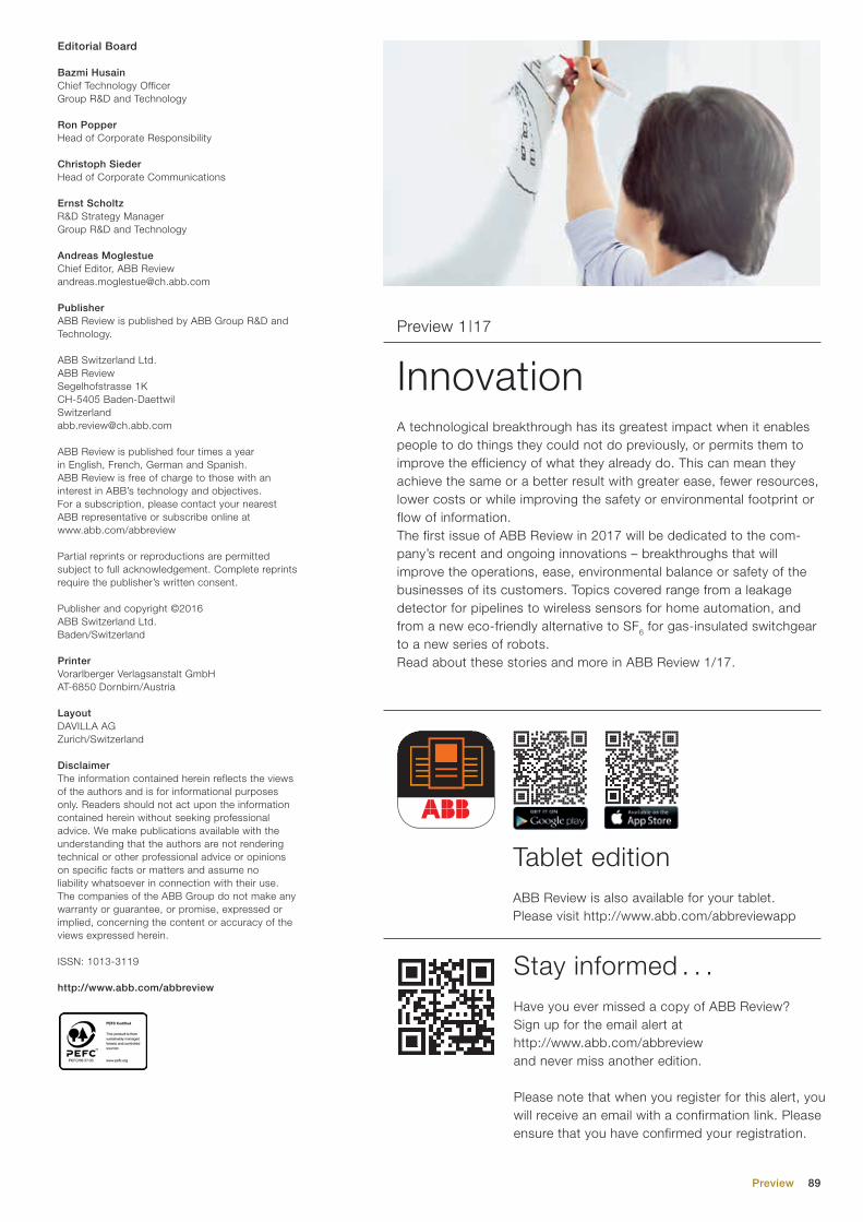
89
A technological breakthrough has its greatest impact when it enables people to do things they could not do previously, or permits them to improve the efficiency of what they already do. This can mean they achieve the same or a better result with greater ease, fewer resources, lower costs or while improving the safety or environmental footprint or flow of information. The first issue of ABB Review in 2017 will be dedicated to the com-pany’s recent and ongoing innovations – breakthroughs that will improve the operations, ease, environmental balance or safety of the businesses of its customers. Topics covered range from a leakage detector for pipelines to wireless sensors for home automation, and from a new eco-friendly alternative to SF6 for gas-insulated switchgear to a new series of robots.Read about these stories and more in ABB Review 1/17.
InnovationPreview 1|17
Have you ever missed a copy of ABB Review? Sign up for the email alert at http://www.abb.com/abbreview and never miss another edition.
Please note that when you register for this alert, you will receive an email with a confirmation link. Please ensure that you have confirmed your registration.
ABB Review is also available for your tablet. Please visit http://www.abb.com/abbreviewapp
Stay informed . . .
Tablet edition
Preview
Editorial Board
Bazmi HusainChief Technology OfficerGroup R&D and Technology
Ron PopperHead of Corporate Responsibility
Christoph SiederHead of Corporate Communications
Ernst ScholtzR&D Strategy ManagerGroup R&D and Technology
Andreas MoglestueChief Editor, ABB [email protected]
PublisherABB Review is published by ABB Group R&D and Technology.
ABB Switzerland Ltd.ABB ReviewSegelhofstrasse 1K CH-5405 [email protected]
ABB Review is published four times a year in English, French, German and Spanish. ABB Review is free of charge to those with an interest in ABB’s technology and objectives. For a sub scription, please contact your nearest ABB representative or subscribe online at www.abb.com/abbreview
Partial reprints or reproductions are per mitted subject to full acknowledgement. Complete reprints require the publisher’s written consent.
Publisher and copyright ©2016ABB Switzerland Ltd.Baden/Switzerland
PrinterVorarlberger Verlagsanstalt GmbHAT-6850 Dornbirn/Austria
LayoutDAVILLA AGZurich/Switzerland
DisclaimerThe information contained herein reflects the views of the authors and is for informational purposes only. Readers should not act upon the information contained herein without seeking professional advice. We make publications available with the understanding that the authors are not rendering technical or other professional advice or opinions on specific facts or matters and assume no liability whatsoever in connection with their use. The companies of the ABB Group do not make any warranty or guarantee, or promise, expressed or implied, concerning the content or accuracy of the views expressed herein.
ISSN: 1013-3119
http://www.abb.com/abbreview

90 ABB review 4|16
ABB review 1|16 ABB review 2|16
6 12
18
23
30
34
41
49
53
60
65
70
6
9
14
17
20
24
28
30
34
37
40
45
50
52
55
61
68
73
Innovation highlightsABB’s top innovations for 2016Small wonderStation service voltage transformers for small power requirementsA flexible friendABB’s flexible tank concept for transformers mitigates rupture riskProtect and surviveFault protection analysis in low-voltage DC microgrids with photovoltaic generatorsTest driveABB’s new test laboratory lets customers optimize motor/drive combinationsDriving forceRare-earth-free electric motors with ultrahigh efficiencies deliver sustainable and reliable solutionsTwist offDamping torsional oscillations at the intersection of variable-speed drives and elastic mechanical systemsVisionary3-D visualization enhances production operationsPulp mill optimization no longer pulp fictionProducing high-quality pulp consistently with advanced process controlAlarming discoveriesImproving operator effectiveness through alarm life-cycle supportFrom paper to digitalA research project for extracting object-oriented descriptions of piping and instrumentation diagramsOur readers have spokenPresenting the results of our readership survey
A healthy choiceABB’s close relationship with the food and beverage industry is getting closerWhen bytes meet bitesWhat the Internet of Things, Services and People means for the food and beverage industryMix and MESAn ABB manufacturing execution system raises productivity for DSM Nutritional ProductsAssembling flavorsIndustry 4.0 based on IoTSP enables Automation Builder to rapidly virtualize discrete production process-es and machinery in the food industry and beyondA safe investmentFood-safe components in washdown applicationsPalletizing for the palateSelecting ABB’s IRB 460 robot stacks upAn ingredient called innovationInnovations for the food and beverage industryFish taleABB maintenance and operational services for Marine HarvestRecipe for successSimultaneous mass flow rate and density measurement for the food and beverage industrySame again?Consistent flavor is essential in any distilling or brewing operationThe whey forwardReliable and accurate instrumentation for the dairy industryFood powerABB’s rugged UPS PowerLine DPA ensures food and beverage production facilities keep runningStirred, not shakenUltralow harmonic drives keep harmful harmonics out of food and beverages125 yearsABB celebrates 125 years in SwitzerlandPower semiconductorsThe past and present of power semiconductors at ABBIntegrating IT and OTLeveraging operational technology integration with Decathlon ServicesAirPlusTM
An alternative to SF6 as an insulation and switching medium in electrical switchgearPutting a damper on resonanceAdvanced control methods guarantee stable operation of grid-connected low-voltage converters
Innovation Food and beverage
WW
Innovation
W
reviewABB
A sea of innovations 6Rural electrification transformed 12Test-driving drives 303-D visualization 49
1 |16en
The corporatetechnical journal
en
W
reviewABB 2 |16
en
The corporatetechnical journal
Serving the industry à la carte 6Feeding data to grow productivity 9Food-safe components 20The flavor of consistency 37
Food & beverage
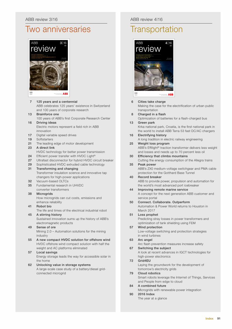
91Index
ABB review 3|16 ABB review 4|16
6
8
13
16
25
30
35
40
44
50
51
57
63
67
72
79
84
90
7
13
16
17192123
24272931
3235
38
41
45
49
55
57
62
Cities take chargeMaking the case for the electrification of urban public transportationCharged in a flash Optimization of batteries for a flash-charged busGreen parkKrka national park, Croatia, is the first national park in the world to install ABB Terra 53 fast DC/AC chargersElectrifying historyA long tradition in electric railway engineeringWeight loss programABB’s Effilight® traction transformer delivers less weight and losses and needs up to 70 percent less oilEfficiency that climbs mountainsCutting the energy consumption of the Allegra trainsPeak powerABB’s ZX0 medium-voltage switchgear and PMA cable protection for the Gotthard Base TunnelRecord breakerABB to provide power, propulsion and automation for the world’s most advanced port icebreakerImproving remote marine serviceA concept for the next generation ABB customer and service portalConnect. Collaborate. OutperformAutomation & Power World returns to Houston in March 2017Loss prophetPredicting stray losses in power transformers and optimization of tank shielding using FEMWind protectionLow-voltage switching and protection strategies in wind turbinesArc angelArc flash prevention measures increase safetySwitching the subjectA look at recent advances in IGCT technologies for high-power electronicsGrid4EULaying the groundwork for the development of tomorrow’s electricity gridsCloud roboticsSmart robots leverage the Internet of Things, Services and People from edge to cloudA combined futureMicrogrids with renewable power integration2016 IndexThe year at a glance
125 years and a centennialABB celebrates 125 years’ existence in Switzerland and 100 years of corporate researchBrainforce one100 years of ABB’s first Corporate Research CenterDriving ideasElectric motors represent a field rich in ABB innovationDigital variable speed drivesSoftstartersThe leading edge of motor developmentA direct linkHVDC technology for better power transmissionEfficient power transfer with HVDC Light®
Ultrafast disconnector for hybrid HVDC circuit breakerSophisticated HVDC extruded cable technologyTransforming and changingTransformer insulation science and innovative tap changers for high-power applicationsVacuum-based OLTCs Fundamental research in UHVDC converter transformersMicrogridsHow microgrids can cut costs, emissions and enhance reliabilityRobot bioThe life and times of the electrical industrial robotA stirring historySustained innovation sums up the history of ABB’s electromagnetic productsSense of oreMining 2.0 – Automation solutions for the mining industryA new compact HVDC solution for offshore windHVDC offshore wind compact solution with half the weight and AC platforms eliminatedLocal savingsEnergy storage leads the way for accessible solar in the homeUnlocking value in storage systemsA large-scale case study of a battery/diesel grid-connected microgrid
Two anniversaries TransportationW
reviewABB 3 |16
en
The corporatetechnical journal
125 years in Switzerland 7100 years of Corporate Research 13Landmark achievements that changed the world 16Looking to the future 55
Two anniversaries
W
reviewABB 4 |16
en
The corporate technical journal
Charging a bus in 15 seconds 8A long tradition in electric railways 16 World’s longest rail tunnel 35Remote service at sea 44
Transportation

Affix address label here
Deep beneath the Swiss Alps, the world’s longest tunnel, stretching 57 km, is nearing comple-tion. By the end of this year, the Gotthard base tunnel will be traversed daily by 260 freight and 65 passenger trains at speeds of up to 250 km/h, dramatically shortening journey times through the Alps. To help make this engineering feat possible, ABB experts developed custom infrastructure, energy-efficient power distribution, and the largest fresh-air ventilation system ever built.
Main Partner
Our contribution to the future:putting bold ideas solidly on track.