
VXT 325 VXT425 VXT505 TRAILER & TRUCK OPERATION AND PARTS ...
65
VXT 325—VXT425—VXT505 TRAILER & TRUCK OPERATION AND PARTS MANUAL ROTO-MIX LLC P.O. BOX 1724 2205 E. Wyatt Earp Blvd. Dodge City, Kansas 67801 (620) 225-1142 © ROTO-MIX LLC 2006 SERIAL NUMBER_________________ 441930 06/2021 Printed in U.S.A.
Transcript of VXT 325 VXT425 VXT505 TRAILER & TRUCK OPERATION AND PARTS ...

Page 1
VXT 325—VXT425—VXT505 TRAILER & TRUCK
OPERATION AND PARTS MANUAL
ROTO-MIX LLC
P.O. BOX 1724 2205 E. Wyatt Earp Blvd.
Dodge City, Kansas 67801 (620) 225-1142 © ROTO-MIX LLC 2006
SERIAL NUMBER_________________
441930 06/2021 Printed in U.S.A.
Page 2
INTRODUCTION
Congratulations on the purchase of your new Vertical Mixer from ROTO-MIX. With
proper operation and preventative maintenance it will last for years.
This SAFETY ALERT SYMBOL indicates important safety messages in the
manual. When you see this symbol, be alert to the possibility of PERSONAL INJURY
and carefully read the message that follows.
NEVER OPERATE WITHOUT ALL COVERS, SHIELDS AND GUARDS IN
PLACE. KEEP HANDS, FEET AND CLOTHING AWAY FROM MOVING PARTS.
Some covers and guards have been removed for illustrative/photographic
purposes only in this manual. However, equipment should never be operated in
this condition. Keep all shields in place. If shield removal becomes necessary for
repairs, replace the shield prior to use.
The Guarantee appears in the front of this book along with the Registration and
Inspection Certificate.
For information on ordering repair parts, refer to the Repair Parts section at the
back of this book.
The serial number plate is located on the drivers side lower front of the main frame.
This number should be recorded on the Registration and Inspection Certificate for
your reference and for proper identification of your mixer by ROTO-MIX.
You are urged to study this manual and follow the instructions carefully. Your
efforts will be repaid in better operation and service as well as a savings in time
and repair expense.
Failure to read this manual and understand the safe operation of the mixer could
lead to serious injury.
If you do not understand the instructions in this manual contact either your dealer
or ROTO-MIX at Dodge City, Kansas 67801.
This supersedes all previous published instructions.
ROTO-MIX LLC warrants to the original purchaser all products manufactured by it to be free from defects in material and workmanship under normal use and service. ROTO-MIX’s obligation under this warranty is limited to repairing or replacing, as the company may elect, free of charge and without charge for installation, at the place of business of a dealer or distributor author-ized to handle the equipment covered by this warranty or at a ROTO-MIX facility, any parts that prove, in the company’s judgment, to be defective in material or workmanship within one (1) year after delivery to the original purchaser, and still owned by the original purchaser. This warranty shall in no way make ROTO-MIX liable to anyone for personal injuries or damages, loss of time, or expense of any kind either direct or indi-rect resulting from part failure or defect. This warranty is subject to acts of God, fire and existing conditions of supply and demand, or production, or ability or inability to deliver, or for any other valid reason beyond the reasonable control of ROTO-MIX, to obtain materials, manufactured replacement parts, or make delivery thereof. No distributor, dealer, agent, or ROTO-MIX employee (other than the CEO or President in writing) is authorized to extend any other or further express or implied warranty or incur any additional obligation on ROTO-MIX’s behalf in connection with the sale of this product. If ROTO─MIX, or its duly authorized representative, shall find that such returned part or parts are defective and such defects, or defect, are included in and covered by said warranty, then such defective part or parts shall promptly be replaced without charge to the purchaser, F.O.B. the ROTO─MIX plant. Product Registration - It is a condition of this warranty that the original purchaser must fill out the warranty card furnished by ROTO-MIX and that it be returned to ROTO-MIX within 10 days of purchase and be re-corded in ROTO-MIX’s owner file for this warranty to be valid. In the event an owner’s card is not on file at the ROTO-MIX office, the warranty period will extend only from date equipment was picked up or shipped from the ROTO-MIX plant. Maintenance - It is the customer’s responsibility to maintain their equipment in accordance with the instruc-tions provided in the Operator’s Manual. ROTO-MIX recommends that you keep records and receipts; you may be asked to prove that maintenance instructions have been followed. Operation – It is the customer’s responsibility to operate the equipment only for the purpose for which it was designed and in accordance with all safety and operational recommendations contained in the Opera-tors Manual. If a defect in materials or workmanship occurs, it is the customer’s responsibility to cease oper-ating the equipment until authorized repairs are made. Damage, which occurs from continued operation, may not be covered by this warranty. What this Warranty Covers This warranty covers failures caused by defects in materials or workmanship only. This Warranty does not cover failures caused by:
- Improper operation
- Natural calamities
- Unauthorized modifications
- Unauthorized repairs
- Use of Non ROTO-MIX parts
- Neglected maintenance
- The use of PTO Shaft
Adaptors
- Usage contrary to the
intended purpose of the
product
Warranty continues on the next page.
Page 3
SCALES WARRANTY & SERVICE POLICY
DIGI-STAR SCALE SYSTEMS Digi-Star, LLC warrants for a period of one year from date of installation, to correct by repair or replacement, at Digi-Star’s option, any defect in material or workmanship in any part of this product. In the event of replacement, Digi-Star’s sole obligation shall be to provide replacement products or parts. F.O.B. Digi-Star, LLC, W5527 Hwy 106, Fort Atkinson, WI 53538 USA. WEIGH-TRONIX SCALE SYSTEMS WEIGH-TRONIX warrants for a period of one year from date of installation, to correct by repair or replacement, at Weigh-Tronix’s option, any defect in material or workmanship in any part of this product. In the event of replacement, Weigh-Tronix’s sole obligation shall be to provide replacement products or parts. F.O.B. Avery Weigh-Tronix, 1000 Armstrong Drive, Fairmont, MN 56031-1439 USA.
Limited Warranty Statement continued This Warranty does not cover replacement of Wear or Maintenance Items including, but not limited to.
This Warranty does not cover: - Pickup and delivery of the equipment
- Service Calls or Travel Time to and from sites
- Rental of replacement equipment during repair period
- Products that have been declared a total loss and subsequently salvaged
- Overtime labor charges
- ROTO-MIX is not responsible and will not be liable for damage caused to persons or property, commercial loss, loss of time or production, loss of use by reason of the installation or use of ROTO-MIX products or their mechanical failure.
Right to Make Changes ROTO-MIX reserves the right to make any changes to a ROTO-MIX product at any time without incurring any obligation with respect to any product previously ordered, sold or shipped, with or without notice. Parts Warranty ROTO-MIX warranties replacement parts against defects in materials or workmanship for a period of 90 days or the remainder of the product warranty, whichever is longer. Remedy for defective replacement parts for units that are beyond the original product warranty, will be limited to replacement of the failed part. Failures that are due to damage, improper installation, lack of maintenance or improper operation will not be covered. ROTO-MIX 2205 East Wyatt Earp Blvd., Dodge City, KS 67801 (620) 225-1142 Fax: (620) 225-6370
- Lubricants
- Filters
- Hoses
- Tires
- Augers
- Wipers
- Chains
- Idlers
- Batteries
- Blades
- Belts
Page 4
Page 5
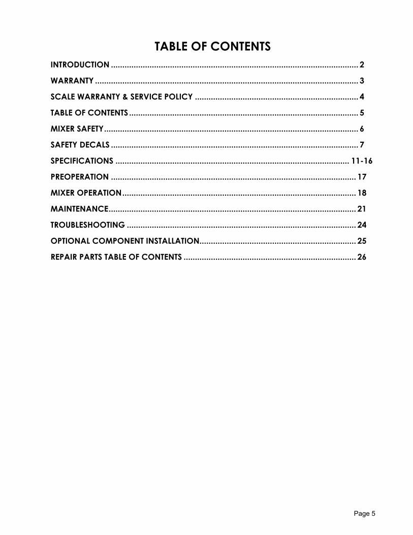
TABLE OF CONTENTS
INTRODUCTION ............................................................................................................. 2
WARRANTY .................................................................................................................... 3
SCALE WARRANTY & SERVICE POLICY ........................................................................ 4
TABLE OF CONTENTS ..................................................................................................... 5
MIXER SAFETY ................................................................................................................ 6
SAFETY DECALS ............................................................................................................. 7
SPECIFICATIONS ....................................................................................................... 11-16
PREOPERATION ............................................................................................................ 17
MIXER OPERATION ....................................................................................................... 18
MAINTENANCE ............................................................................................................. 21
TROUBLESHOOTING ..................................................................................................... 24
OPTIONAL COMPONENT INSTALLATION..................................................................... 25
REPAIR PARTS TABLE OF CONTENTS ............................................................................ 26
Page 6
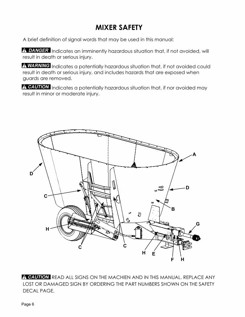
MIXER SAFETY
A brief definition of signal words that may be used in this manual:
Indicates an imminently hazardous situation that, if not avoided, will
result in death or serious injury.
Indicates a potentially hazardous situation that, if not avoided could
result in death or serious injury, and includes hazards that are exposed when
guards are removed.
Indicates a potentially hazardous situation that, if nor avoided may
result in minor or moderate injury.
READ ALL SIGNS ON THE MACHIEN AND IN THIS MANUAL. REPLACE ANY
LOST OR DAMAGED SIGN BY ORDERING THE PART NUMBERS SHOWN ON THE SAFETY
DECAL PAGE.
D
D
C
H
C C H
A
B
G
H F E
Page 7
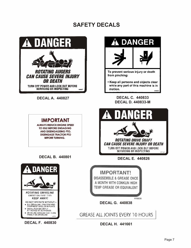
SAFETY DECALS
DE CAL A. 440827 DE CAL C. 440833DE CAL D. 440833-M
DE CAL B. 440801 DE CAL E. 440826
DE CAL F. 440830
DE CAL G. 440838
DE CAL H. 441661
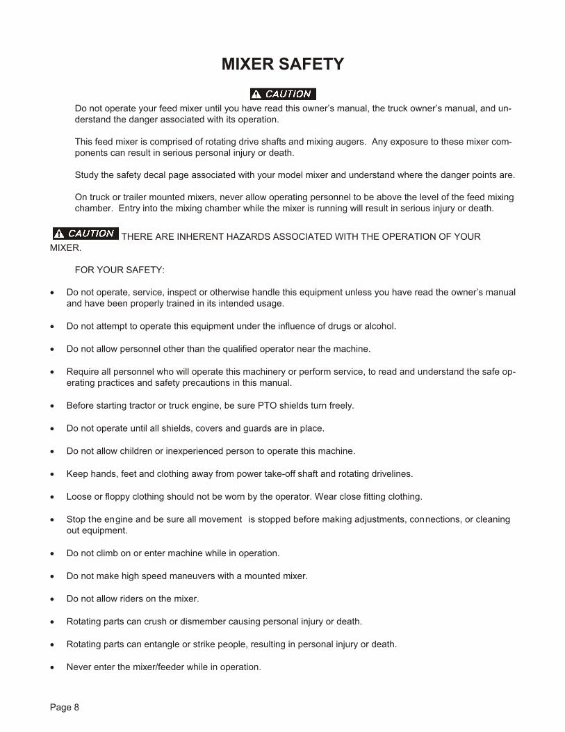
MIXER SAFETY
Do not op er ate your feed mixer un til you have read this owner’s man ual, the truck owner’s man ual, and un -derstand the danger associated with its operation.
This feed mixer is com prised of ro tat ing drive shafts and mix ing au gers. Any ex po sure to these mixer com -po nents can re sult in se ri ous per sonal in jury or death.
Study the safety de cal page as so ci ated with your model mixer and un der stand where the dan ger points are.
On truck or trailer mounted mix ers, never al low op er at ing per son nel to be above the level of the feed mix ing cham ber. Entry into the mix ing cham ber while the mixer is run ning will re sult in se ri ous in jury or death.
THERE ARE INHERENT HAZARDS ASSOCIATED WITH THE OPERATION OF YOURMIXER.
FOR YOUR SAFETY:
· Do not op er ate, ser vice, in spect or oth er wise han dle this equip ment un less you have read the owner’s man ual and have been properly trained in its in tended us age.
· Do not at tempt to op er ate this equip ment un der the in flu ence of drugs or al co hol.
· Do not al low per son nel other than the qual i fied op er a tor near the ma chine.
· Re quire all per son nel who will op er ate this ma chin ery or per form ser vice, to read and un der stand the safe op -er ating prac tices and safety pre cau tions in this man ual.
· Be fore start ing trac tor or truck en gine, be sure PTO shields turn freely.
· Do not op er ate un til all shields, covers and guards are in place.
· Do not al low children or in ex pe ri enced per son to op er ate this ma chine.
· Keep hands, feet and cloth ing away from power take-off shaft and ro tating drivelines.
· Loose or floppy cloth ing should not be worn by the op er a tor. Wear close fitting cloth ing.
· Stop the en gine and be sure all movement is stopped before making adjustments, con nec tions, or cleaningout equip ment.
· Do not climb on or en ter ma chine while in op er a tion.
· Do not make high speed ma neu vers with a mounted mixer.
· Do not al low riders on the mixer.
· Ro tating parts can crush or dis mem ber caus ing per sonal in jury or death.
· Ro tating parts can en tan gle or strike peo ple, re sult ing in per sonal in jury or death.
· Never en ter the mixer/feeder while in op er a tion.
Page 8
· Op er ate the mixer/feeder from the op er a tor’s seat only.
· Stay clear of ro tating drivelines.
· En tan gle ment in ro tating drive line can cause se ri ous in jury or death.
· Keep trac tor mas ter shield and driveline shields in place at all times.
· Make sure ro tating shields turn freely.
· Do not ex ceed load ca pac ity of the mixer/feeder. (See load ing in struc tions).
· Re duce speed when turning or traveling on rough terrain. Avoid traveling over loose fill, rocks, ditches orholes.
· Do not operate on steep slopes as overturn may result. operate up and down (not across) intermediateslopes. Avoid sudden starts and stops. Pick the most level possible route when transporting across fields.Avoid the edges of ditches or gul lies and steep hill sides.
· Keep trans mis sion in gear when traveling down hill.
· Keep sparks, lighted matches, and open flame away from the top of bat tery. Bat tery gas can ex plode.
· Avoid over head wires or other ob sta cles. Con tact with over head lines could cause se ri ous in jury or death.
· As a precaution, al ways recheck the hardware on mixer/feeder following ev ery 100 hours of operation. Cor -rect all prob lems. fol low the main te nance safety pro ce dures.
FAIL URE TO HEED MAY RE SULT IN SE RI OUS PER SONAL IN JURY OR DEATH.
THERE ARE AD DI TIONAL HAZ ARDS AS SO CI ATED WITH THE SER VICE AND MAIN TE -NANCE OF YOUR MIXER.
FOR YOUR SAFETY:
· Dis en gage power take-off and re move keys from trac tor or truck be fore ser vicing a mixer.
· Do not at tempt to clean, oil or ad just mixer while it is in mo tion.
· Stop the en gine and be sure all movement is stopped before making adjustments, connections, or cleaningout equip ment. Dis con nect trac tor PTO shaft.
· Make sure there is plenty of ven ti la tion. Never op er ate ve hi cle en gine in a closed build ing. The ex haust fumes may cause asphyxiation.
· Be fore work ing on the mixer/feeder, stop the tow ing ve hi cle, set the brakes, disengage the PTO and all powerdrives, shut off the en gine and re move the ig ni tion keys.
· Be cer tain all mov ing parts on at tach ments have come to a com plete stop be fore at tempt ing to per form main -tenance.
· Be fore en tering mixing cham ber or ser vicing mixer, dis en gage power take-off and re move keys from trac tor or truck to prevent accidental start-up.
Page 9
· Do not work under a trailer mixer without supporting with suitable support stands. Always use a safety sup -port and block the wheels. Never use a jack to sup port the ma chine.
· Do not work un der a mixer with out blocking the wheels to pre vent rolling.
· A fire ex tin guisher and first aid kit should be kept readily accessible while performing maintenance on thismixer/feeder.
· Never check bat tery charge by placing a metal ob ject across the posts. Use a volt-me ter or hy drom e ter.
· Do not charge a frozen bat tery; it may ex plode. Warm bat tery to 16°c(60°f)
· Es cap ing hydraulic fluid un der pres sure can pen e trate the skin causing se ri ous in jury or death. Avoid the haz -ard by relieving hydraulic pressure be fore dis con necting hy drau lic or other lines. Tighen all connections be -fore ap plying pres sure.
· Search for hydraulic leaks with a piece of cardboard. Protect hands and body from high pressure fluids. Never use your hands to lo cate hy drau lic leaks on at tach ments.
· Re place all shields and guards af ter ser vic ing and be fore mov ing.
· Do not al low grease or oil to build up on any step or plat form.
· Never re place hex bolts with less than grade five (5) bolts unless otherwise specified.
FAIL URE TO HEED MAY RE SULT IN SE RI OUS PER SONAL IN JURY OR DEATH.
REMEMBER: Your best as sur ance against ac ci dents is a care ful and re spon si ble op er a tor. If there is any por tion of thisman ual or func tion you do not un der stand, con tact your dealer or the ROTO-MIX plant.
SAFETY DE CAL CARE
1. Keep safety decals and signs clean and legible at all times.2. Replace safety decals and signs that are missing or have become illegible.3. Replaced parts that displayed a safety sign should also display the current sign.4. Safety decals or signs are available from your dealer or the ROTO-MIX manufacturing plant.5. How to Install Safety Decals:
A. Be sure that the installation area is clean and dry.B. Decide on the exact position before you remove the backing paper.C. Remove the smallest portion of the split backing paper.D. Align the decal over the specified area and carefully press the small portion with the exposed sticky
backing in place.E. Slowly peel back the remaining paper and carefully smooth the remaining portion of the decal in place.F. Small air pockets can be pierced with a pin and smoothed out using the piece of decal backing paper.
FAIL URE TO HEED MAY RE SULT IN SE RI OUS PER SONAL IN JURY OR DEATH.
Page 10
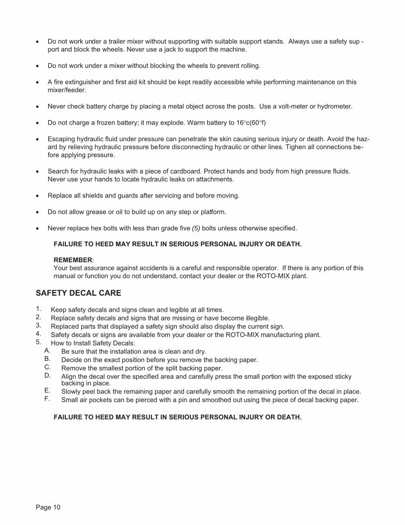
85"
84"
89 3/4"
90 1/4"
26 1/4"
36 3/4"
27 1/2"26"32"
30.00°
94 1/4"
3' CONVEYOR
2' CONVEYOR
159 1/2"
207"
325 VXT TRAILER DIMENSIONAL ILLUSTRATION
SPECIFICATIONS
9 1/2"
17 3/4"
WITHOUT CONVEYOR
All Dimensions & Specifications are Approximate & Subject to Change Without Notice.
Page 11
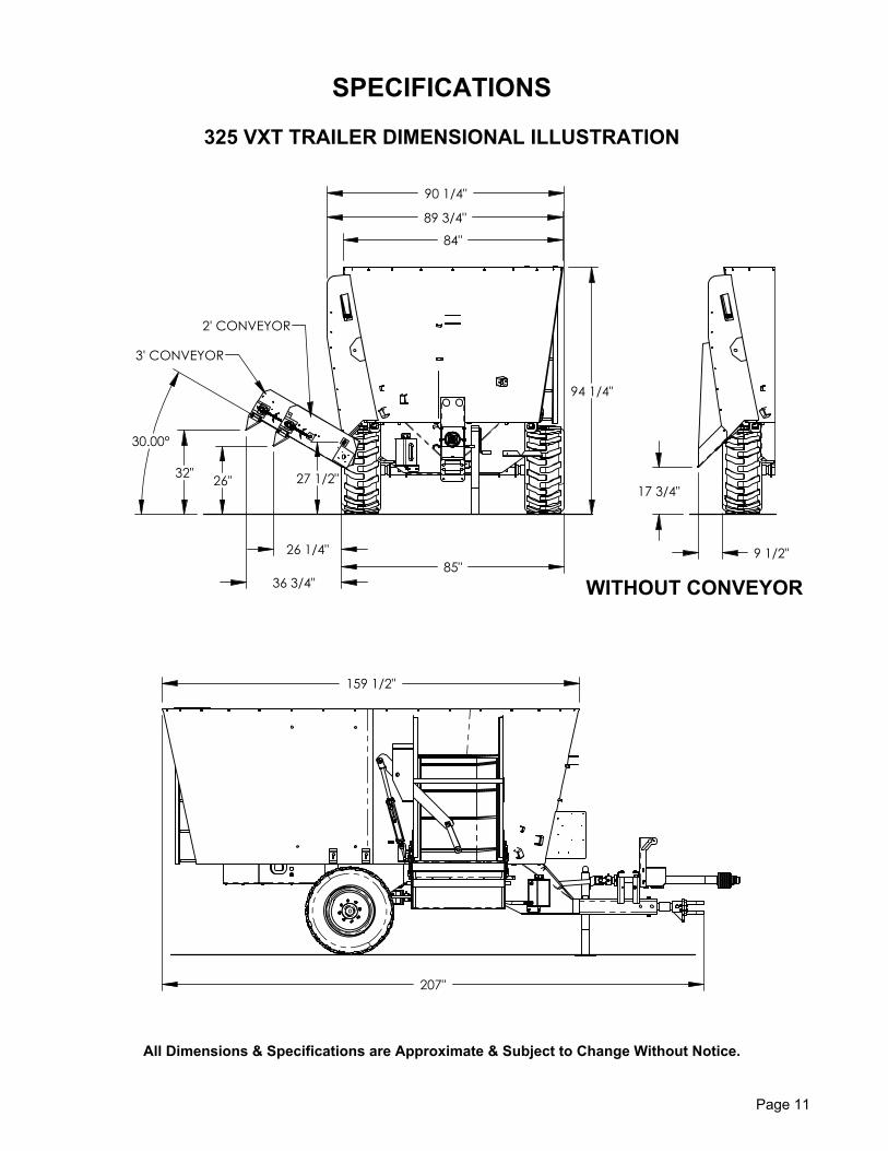
90 5/8"
94 7/8"
108"15"
25 1/2"
25 1/2"
30.00°
21"
19 3/8"
96 3/4"
3' CONVEYOR
2' CONVEYOR
180 1/8"
217 1/4"
136 3/4"
VXT 425 TRAILER DIMENSIONAL ILLUSTRATION
All Dimensions & Specifications are Approximate & Subject to Change Without Notice.
Page 12
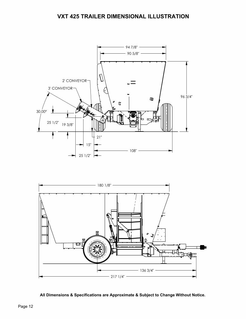
108"
90"
93 1/4"
14 3/4"
25 1/4"
19 1/4"25 1/4" 21"
30.00°
108 3/4"3' CONVEYOR
2' CONVEYOR
180 1/4"
217 1/4"
VXT 505 TRAILER DIMENSIONAL ILLUSTRATION
All Dimensions & Specifications are Approximate & Subject to Change Without Notice.
Page 13
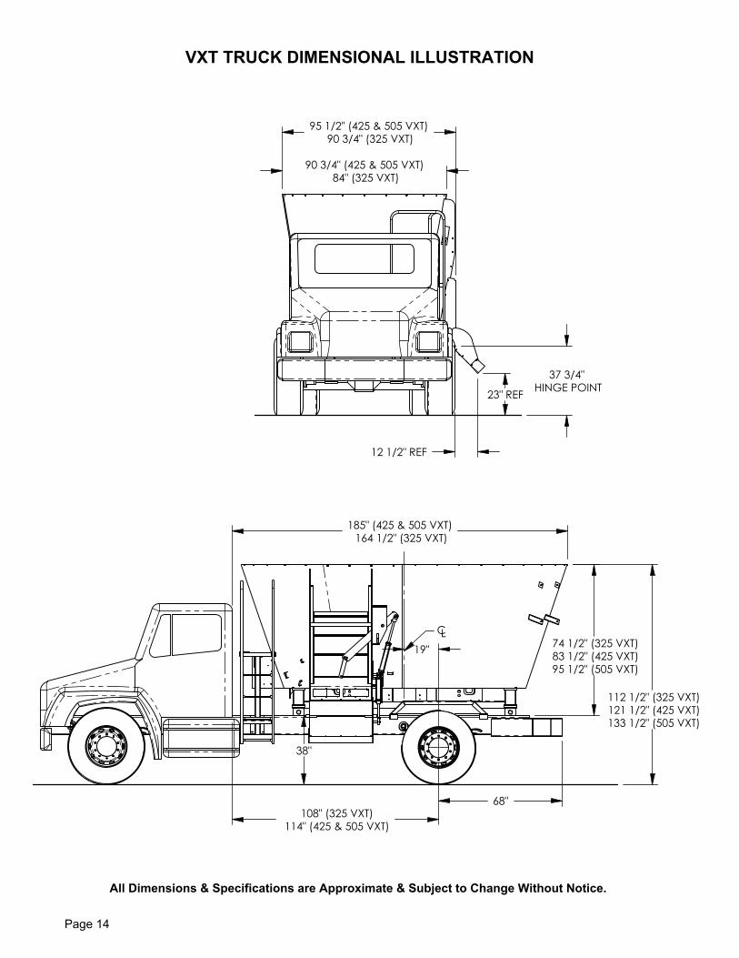
114" (425 & 505 VXT)108" (325 VXT)
83 1/2" (425 VXT)95 1/2" (505 VXT)
74 1/2" (325 VXT)
185" (425 & 505 VXT)164 1/2" (325 VXT)
68"
121 1/2" (425 VXT)133 1/2" (505 VXT)
112 1/2" (325 VXT)
38"
19"
CL
VXT TRUCK DIMENSIONAL ILLUSTRATION
All Dimensions & Specifications are Approximate & Subject to Change Without Notice.
90 3/4" (425 & 505 VXT)84" (325 VXT)
23" REF
95 1/2" (425 & 505 VXT)90 3/4" (325 VXT)
12 1/2" REF
37 3/4"HINGE POINT
Page 14
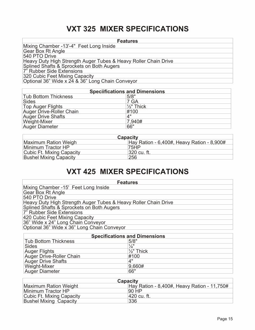
VXT 325 MIXER SPEC I FI CA TIONS
VXT 425 MIXER SPEC I FI CA TIONS
Page 15
Fea turesMix ing Cham ber -15' Feet Long In sideGear Box Rt An gle540 PTO DriveHeavy Duty High Strength Au ger Tubes & Heavy Roller Chain DriveSplined Shafts & Sprock ets on Both Au gers7” Rub ber Side Ex ten sions420 Cu bic Feet Mix ing Ca pac ity 36” Wide x 24” Long Chain Con veyorOp tional 36” Wide x 36” Long Chain Con veyor
Spec ifications and Di mensionsTub Bot tom Thick ness 5/8"Sides ¼"Auger Flights ½" ThickAu ger Drive-Roller Chain #100Au ger Drive Shafts 4"Weight-Mixer 9,660#Auger Diameter 66"
Ca pacityMaximum Ration Weight Hay Ra tion - 8,400#, Heavy Ra tion - 11,750#Mini mum Tracto r HP 90 HPCubic Ft. Mixing Capacity 420 cu. ft.Bushel Mixing Capacity 336
Fea turesMix ing Cham ber -13'-4" Feet Long In sideGear Box Rt An gle540 PTO DriveHeavy Duty High Strength Au ger Tubes & Heavy Roller Chain DriveSplined Shafts & Sprock ets on Both Au gers7” Rub ber Side Ex ten sions320 Cu bic Feet Mix ing Ca pac ity Op tional 36” Wide x 24 & 36” Long Chain Con veyor
Spec iifications and Di mensionsTub Bot tom Thick ness 5/8"Sides 7 GATop Au ger Flights ½" ThickAu ger Drive-Roller Chain #100Au ger Drive Shafts 4"Weight-Mixer 7,940#Auger Diameter 66"
Ca pacityMaximum Ration Weigh Hay Ra tion - 6,400#, Heavy Ra tion - 8,900#Mini mum Tractor HP 75HPCubic Ft. Mixing Capacity 320 cu. ft.Bushel Mixing Capacity 256
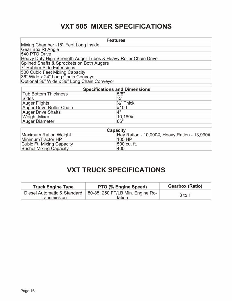
VXT 505 MIXER SPEC I FI CA TIONS
VXT TRUCK SPECIFICATIONS
Page 16
Fea turesMix ing Cham ber -15' Feet Long In sideGear Box Rt An gle540 PTO DriveHeavy Duty High Strength Au ger Tubes & Heavy Roller Chain DriveSplined Shafts & Sprock ets on Both Au gers7” Rub ber Side Ex ten sions500 Cu bic Feet Mix ing Ca pac ity 36” Wide x 24” Long Chain Con veyorOp tional 36” Wide x 36” Long Chain Con veyor
Spec ificat ions and Di mensionsTub Bot tom Thick ness 5/8"Sides ¼"Auger Flights ½" ThickAu ger Drive-Roller Chain #100Au ger Drive Shafts 4"Weight-Mixer 10,180#Auger Diameter 66"
Ca pacityMaximum Ration Weight Hay Ra tion - 10,000#, Heavy Ra tion - 13,990#Mini mum Tracto r HP 105 HPCubic Ft. Mixing Capacity 500 cu. ft.Bushel Mixing Capacity 400
Truck En gine Type PTO (% En gine Speed) Gear box (Ra tio)Diesel Automatic & Standard
Transmission80-85, 250 FT/LB Min. En gine Ro -
tatio n 3 to 1
PREOP ERATIONTHIS MA CHINE RE QUIRES
AN OP ER A TOR. DO NOT LEAVE UN AT -TENDED.
TRAC TOR DRAWBAR
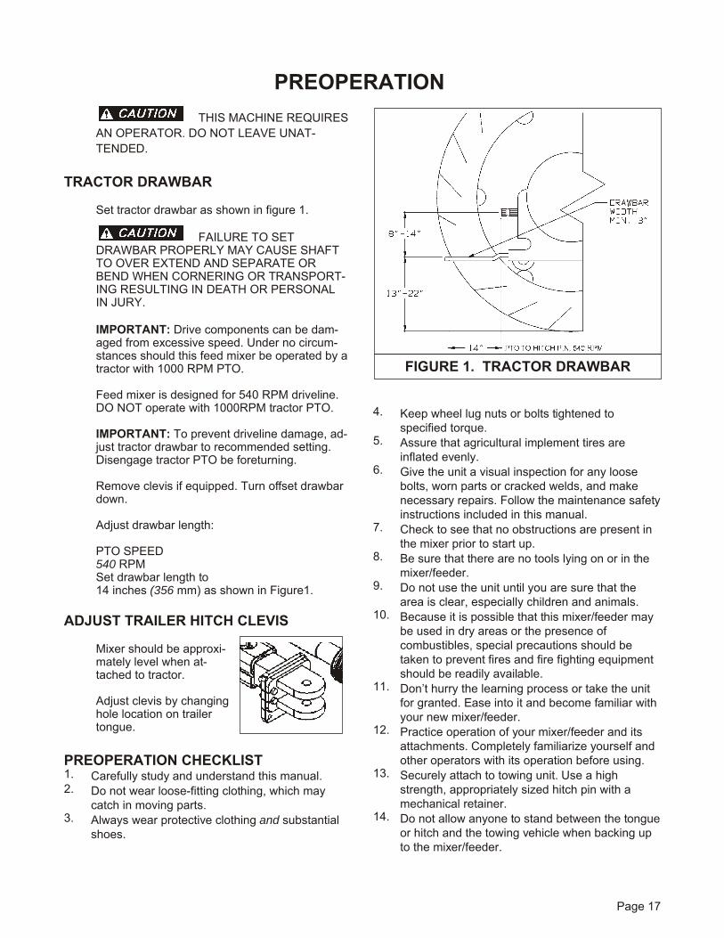
Set trac tor drawbar as shown in fig ure 1.
FAIL URE TO SETDRAWBAR PROP ERLY MAY CAUSE SHAFTTO OVER EX TEND AND SEP A RATE ORBEND WHEN COR NER ING OR TRANS PORT -ING RE SULT ING IN DEATH OR PER SONALIN JURY.
IM POR TANT: Drive com po nents can be dam -aged from ex ces sive speed. Un der no cir cum -stances should this feed mixer be op er ated by atrac tor with 1000 RPM PTO.
Feed mixer is de signed for 540 RPM driveline.DO NOT op er ate with 1000RPM trac tor PTO.
IM POR TANT: To pre vent driveline dam age, ad -just trac tor drawbar to rec om mended set ting.Disengage tractor PTO be fore turning.
Re move clevis if equipped. Turn off set drawbardown.
Adjust drawbar length:
PTO SPEED540 RPMSet drawbar length to 14 inches (356 mm) as shown in Figure1.
AD JUST TRAILER HITCH CLEVIS
Mixer should be ap prox i -mately level when at -tached to trac tor.
Ad just clevis by chang ing hole lo ca tion on trailertongue.
PREOP ERATI ON CHECK LIST1. Carefully study and understand this manual.2. Do not wear loose-fitting clothing, which may
catch in moving parts.3. Always wear protective clothing and substantial
shoes.
4. Keep wheel lug nuts or bolts tightened tospecified torque.
5. Assure that agricultural implement tires areinflated evenly.
6. Give the unit a visual inspection for any loosebolts, worn parts or cracked welds, and makenecessary repairs. Follow the maintenance safety instructions included in this manual.
7. Check to see that no obstructions are present inthe mixer prior to start up.
8. Be sure that there are no tools lying on or in themixer/feeder.
9. Do not use the unit until you are sure that thearea is clear, especially children and animals.
10. Because it is possible that this mixer/feeder maybe used in dry areas or the presence ofcombustibles, special precautions should betaken to prevent fires and fire fighting equipmentshould be readily available.
11. Don’t hurry the learning process or take the unitfor granted. Ease into it and become familiar withyour new mixer/feeder.
12. Practice operation of your mixer/feeder and itsattachments. Completely familiarize yourself andother operators with its operation before using.
13. Securely attach to towing unit. Use a highstrength, appropriately sized hitch pin with amechanical retainer.
14. Do not allow anyone to stand between the tongue or hitch and the towing vehicle when backing upto the mixer/feeder.
Page 17
FIG URE 1. TRAC TOR DRAWBAR
MIXER OP ER A TIONPTO EN GAGEM ENT - TRAILER
This mixer is de signed for 540 rpm PTO. DoNot Operate mixer with 1000 rpm trac tor PTO.
Avoid high speed sud den en gage ment of themixer. Do ing so may dam age drive com po nents.
COR NERING - TRAILER
Sharp cor ner ing with the PTO en gaged is notrec om mended. If it is nec es sary to mix whencor ner ing, it should be done at re duced speedsand on wide cor ners only.
LOAD ING IN STRUCTI ONS & PRE CAU -TIONS
1. Visually inspect mixer before each load2. DO NOT overload the mixer. Mixer capacity is
determined by weight. An overloaded mixer willnot mix correctly and will pull harder, which couldcause damage. Maximum weight - see page 15.
3. Be sure the dis charge door is closed be foreadding any ingredients.
4. It is rec om mended that the mixer be op er atedwhile load ing.
DO NOT CLIMB ON OR STANDON MIXER WHILE LOAD ING.
5. Add hay first.6. Add balance of grain and/or commodities,
keeping more fragile ingredients toward the endof the loading sequence as possible. For bestresults, add concentrates or other dry ingredients of small quantity as close to the middle of theloading sequence as possible
7. Load Silage, green chop and/or other highmoisture products.
8. Load molasses, animal fat and/or other liquidsupplements last.
9. View mixing operation only from tractor seat.10. The mixer is equipped with a 3- point elec tronic
scale sys tem. The hitch and each of the two axlespin dles is an elec tronic weigh beam and sendsinformation to the scale indicator to indicate
weight of in gre di ents added. The scale in di ca toris cali brated to com pen sate for the empty weightof the mixer. Com plete de tails for proper scaleoperation are included with the documentation for the scale sys tem.
HAY PREP ARATIO N
SMALL BALES (60 to 150 lbs., 2 or 3 wire),LARGE SQUARE BALES (3' x 4' x 8' or 4' x 4' x8') and ROUND BALES.
Re move all twine, wire and/or wrap ping and load bale in mixer.
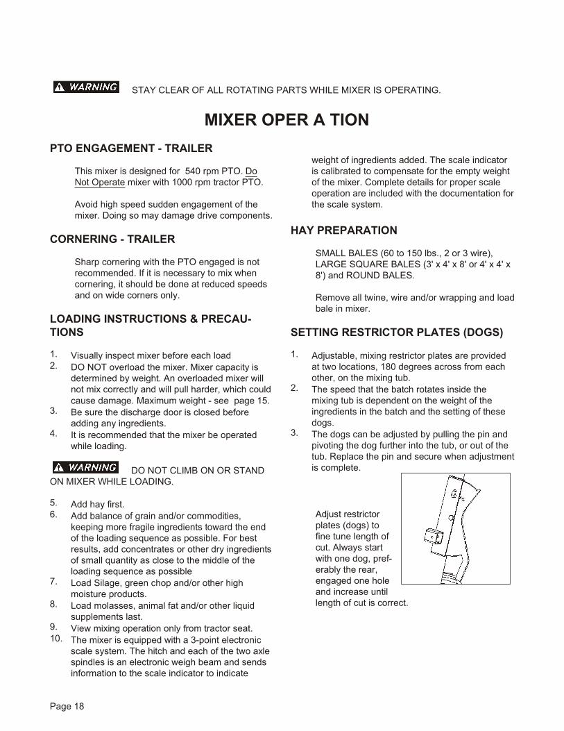
SET TING RESTRICTOR PLATES (DOGS)
1. Ad just able, mix ing restrictor plates are pro videdat two lo ca tions, 180 de grees across from eachother, on the mix ing tub.
2. The speed that the batch ro tates in side themix ing tub is de pend ent on the weight of thein gre di ents in the batch and the set ting of thesedogs.
3. The dogs can be ad justed by pull ing the pin andpiv ot ing the dog fur ther into the tub, or out of thetub. Re place the pin and se cure when ad just ment is com plete.
Adjus t restrictorplates (dogs) tofine tune length ofcut. Al ways startwith one dog, pref -erably the rear,en gaged one holeand in crease un tillength of cut is cor rect.
Page 18
STAY CLEAR OF ALL RO TAT ING PARTS WHILE MIXER IS OP ER AT ING.
4. The dogs should be ex tended no fur ther thannec es sary into the tub and still ob tain sat is fac tory mix ing re sults. This will re sult in min i mum powercon sump tion and min i mum mix ing time. On theother hand, if mix ing qual ity is not con sis tent or ifhay is not be ing prop erly shred ded andin cor po rated into the batch, ex tend these dogsfur ther into the tub. The lighter the weight of thein gre di ents and the higher the con tent of hay is,the fur ther these dogs must ex tend into the tub.
NOTE: Engaging dogs an ex ces sive amountmay cause mix qual ity to de te ri o rate.
MIX ING
Af ter add ing the last in gre di ent, increase thePTO speed to 540 RPM and con tinue the mix ing op er a tion for about 3 to 4 min utes. The ex actmix ing time will be de pend ent on the size of thebatch and dif fer ence in types of in gre di ents.
NOTE: You may find by ex pe ri ence that reg u lat -ing PTO speed other than 540 RPM will im prove mix ing. This will be de pend ent on batch in gre di -ents, batch size, and de sired mix ing time.
DO NOT CLIMB ON THE MIXERTO OBSERVE THE MIXING OPERAT ION. FAILU RETO HEED MAY RE SULT IN SE RI OUS PER SONALIN JURY OR DEATH.
To ob serve the mix ing qual ity, do so as feed isdis charged. DO NOT climb or stand on the ma -chine to ob serve mix ing.
DIS CHARGI NG FEED
1. Begin unloading with PTO drive engaged andmixing augers operating.
2. For mix ers with op tional con veyor, con veyormo tor and con veyor tilt are se quenced so whenthe hy drau lic con trol le ver is moved one way, thecon veyor will ex tend down ward and the con veyor mo tor will be gin to op er ate, fully en gag ing af terthe cyl in der is fully extended.
3. Lower the op tional con veyor and start con veyor.4. Open the dis charge door which is op er ated us ing
separate hydraulic controls.5. For best re sults, off load mix feed at full PTO
speed, and with the door as open as pos si ble. 6. When through feed ing, close the dis charge door,
clear con veyor of all re main ing feed, and retracthydraulic cylinder to lift conveyor.
SHUT DOWN
1. Stop The PTO drive.2. Close the dis charge door.3. Stop the con veyor, if so equipped.
SCALE SWING MOUNT
The scale head is mounted to a swing arm. Theswing arm is de signed to al low scale head view -ing from ei ther side of the mixer or from the trac -tor just by ro tat ing the scale arm be fore load ingor un load ing starts.
SCALE SYS TEM
Re fer to the op er a tion book sup plied with thescale indicator head.
HIGH WAY AND TRANS PORT OP ER A TION
1. Adopt safe driving practices:2. Keep the tractor brake pedals latched together at
all times. Never use independent braking withmachine in tow as loss of control and/or upset ofunit can result.
3. Always drive at a safe speed relative to localconditions and ensure that your speed is lowenough for an emergency stop to be safe andsecure. Keep speed to a minimum.
4. Reduce speed prior to turns to avoid the risk ofoverturning.
5. Avoid sudden uphill turns on steep slopes.6. Always keep the tractor or towing vehicle in gear
to provide engine braking when going downhill.Do not coast.
7. Do not drink and drive.8. Comply with state and local laws governing
highway safety and movement of farm machinery on public roads.
9. Use approved accessory lighting flags andnecessary warning devices to protect operatorsof other vehicles on the highway during daylightand nighttime transport.
10. The use of flashing amber lights is acceptable inmost localities. However, some localities prohibittheir use. Local laws should be checked for allhighway lighting and marking requirements.
11. When transporting the mixer/feeder on the roador highway under 20 MPH (40 KPU) at night orduring the day, use flashing amber warning lightsand a slow moving vehicle (SMV) identificationemblem.
Page 19
12. Plan your route to avoid heavy traffic.13. Be a safe courteous driver. Always yield to
oncoming traffic in all situations, including narrowbridges, intersections, etc.
14. Be observant of bridge loading ratings. Do notcross bridges rated lower than the gross weightat which you are operating.
15. Watch for obstructions overhead and to the sidewhile transporting.
16. Always operate mixer/feeder in a position toprovide maximum visibility at all times. Makeallowances for increased length and weight of the mixer/feeder when making turns, stopping theunit, etc.
LIGHT ING AND MARK ING
It is the re spon si bil ity of the cus tomer to knowthe light ing and mark ing re quire ments of the lo -cal high way au thor i ties and to in stall and main -tain the equip ment to pro vide compliance withthe reg u la tions. Add ex tra lights when trans port -ing at night or dur ing periods of limited visibility.
FOL LOW ING OP ER A TION:
Following operation or when unhitching, stopthe trac tor or tow ing ve hi cle, set the brakes, dis -en gage the PTO and all power drives, shut offthe en gine and re move the ig ni tion keys.
Store the unit in an area away from hu man ac tiv -ity.
Do not park equip ment where it will be ex posedto live stock for long pe ri ods of time. Dam ageand live stock in jury could re sult.
Do not per mit chil dren to play on or around thestored unit.
Make sure parked ma chine is on a hard, levelsur face and en gage all safety de vices.
Wheel chocks may be needed to pre vent unitfrom roll ing.
TRUCK OP ERATI ON
For truck operation and limitat ions, refer to thetruck’s owner man ual.
Page 20
MAIN TE NANCEAL WAYS DIS CON NECT OR DIS EN GAGE POWER TAKE OFF AND RE MOVE KEYS
FROM TRAC TOR OR TRUCK BE FORE CLEANING, AD JUSTING, LUBRICATING OR SER VICING THISMA CHINE. FAIL URE TO HEED MAY RE SULT IN SE RI OUS PER SONAL IN JURY OR DEATH.
The low ered po si tion of the conveyor is lim ited by the me chan i cal in ter fer ence of the bot tom of the chuteand the bot tom of the con veyor.
READ THE FOL LOW ING BE FORE WELD ING ON THIS MIXER/FEEDER
When weld ing on your mixer/feeder, do not al low the cur rent to flow through the ball bear ings or the rollerchains. Ground di rectly to the item be ing welded.
Al ways dis con nect the scale in stru men ta tion from the weigh bars or load cells and the power source. Besure the cur rent does not pass through weigh bars or load cells or scale in di ca tor. The al ter na tor should al -ways be dis con nected if the mixer/feeder is not dis con nected from the tow ing ve hi cle.
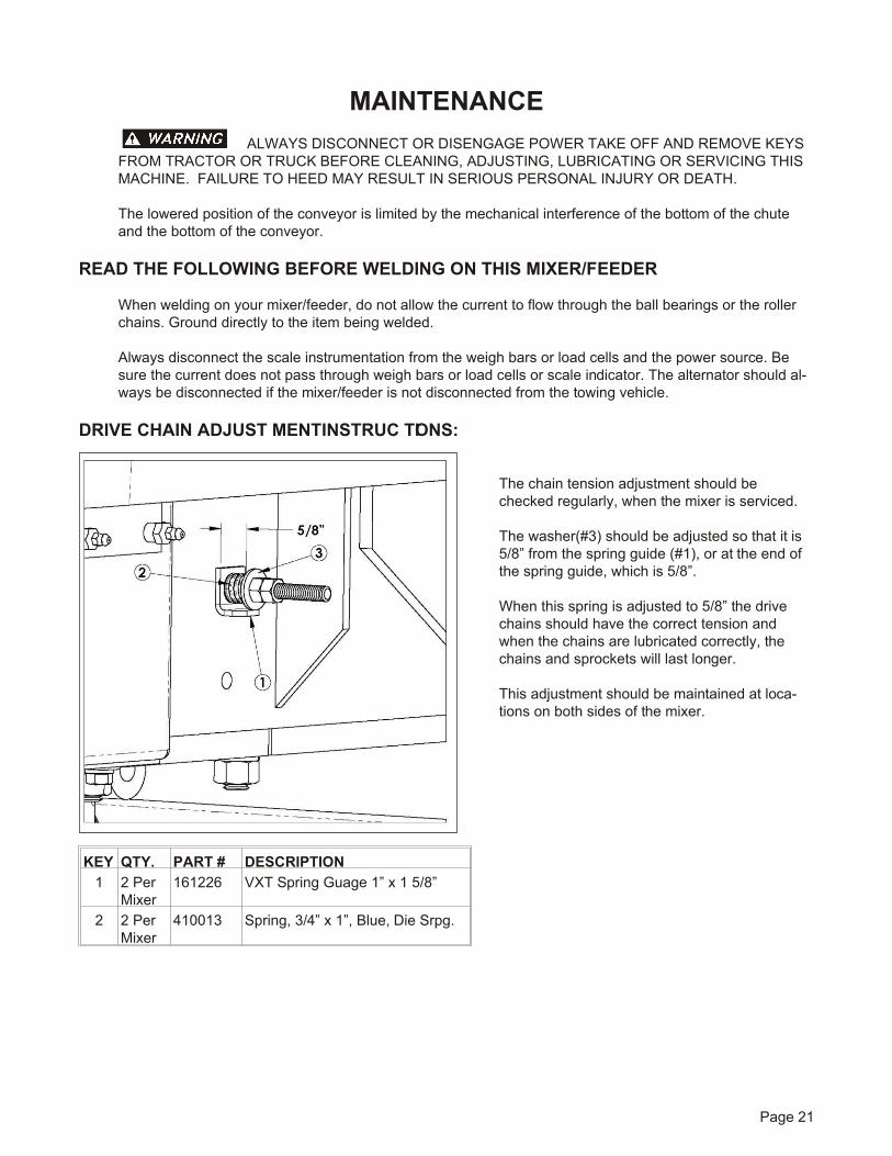
DRIVE CHAIN AD JUST MENT IN STRUC TIONS:
The chain ten sion ad just ment should bechecked reg u larly, when the mixer is ser viced.
The washer(#3) should be ad justed so that it is5/8” from the spring guide (#1), or at the end ofthe spring guide, which is 5/8”.
When this spring is ad justed to 5/8” the drivechains should have the cor rect ten sion andwhen the chains are lu bri cated cor rectly, thechains and sprock ets will last lon ger.
This ad just ment should be main tained at lo ca -tions on both sides of the mixer.
Page 21
KEY QTY. PART # DE SCRIP TION1 2 Per
Mixer161226 VXT Spring Guage 1” x 1 5/8”
2 2 PerMixer
410013 Spring, 3/4” x 1”, Blue, Die Srpg.
See Di a gram on Page 23.
Page 22
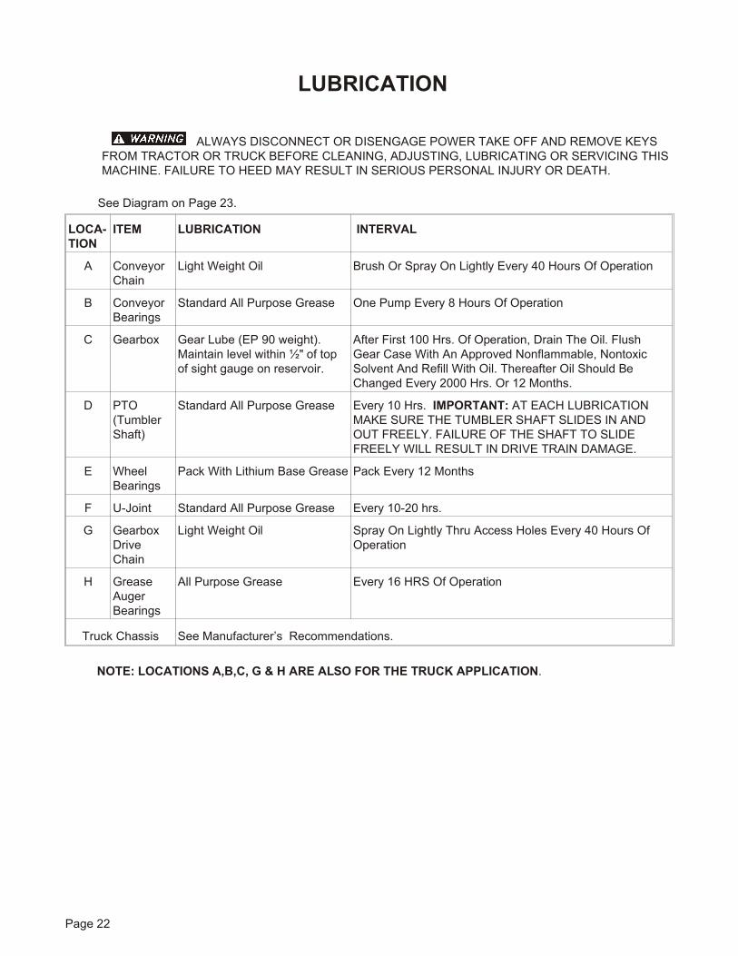
LU BRICAT ION
AL WAYS DIS CON NECT OR DIS EN GAGE POWER TAKE OFF AND RE MOVE KEYSFROM TRAC TOR OR TRUCK BE FORE CLEANING, AD JUSTING, LU BRI CATING OR SER VICING THISMA CHINE. FAIL URE TO HEED MAY RE SULT IN SE RI OUS PER SONAL IN JURY OR DEATH.
LO CA -TION
ITEM LU BRICAT ION IN TER VAL
A ConveyorChain
Light Weight Oil Brush Or Spray On Lightly Ev ery 40 Hours Of Op er a tion
B ConveyorBearings
Stan dard All Pur pose Grease One Pump Ev ery 8 Hours Of Op er a tion
C Gearbox Gear Lube (EP 90 weight).Main tain level within ½" of topof sight gauge on res er voir.
Af ter First 100 Hrs. Of Op er a tion, Drain The Oil. FlushGear Case With An Ap proved Non flam ma ble, Non toxicSol vent And Re fill With Oil. There af ter Oil Should BeChanged Ev ery 2000 Hrs. Or 12 Months.
D PTO(TumblerShaft)
Stan dard All Pur pose Grease Ev ery 10 Hrs. IM POR TANT: AT EACH LU BRI CA TIONMAKE SURE THE TUM BLER SHAFT SLIDES IN ANDOUT FREELY. FAIL URE OF THE SHAFT TO SLIDEFREELY WILL RE SULT IN DRIVE TRAIN DAM AGE.
E WheelBearings
Pack With Lith ium Base Grease Pack Ev ery 12 Months
F U-Joint Stan dard All Pur pose Grease Ev ery 10-20 hrs.
G GearboxDriveChain
Light Weight Oil Spray On Lightly Thru Ac cess Holes Ev ery 40 Hours OfOperation
H GreaseAugerBearings
All Pur pose Grease Ev ery 16 HRS Of Operation
Truck Chas sis See Manufacturer’s Recommendations.
NOTE: LO CA TIONS A,B,C, G & H ARE ALSO FOR THE TRUCK AP PLI CA TION.
Page 23
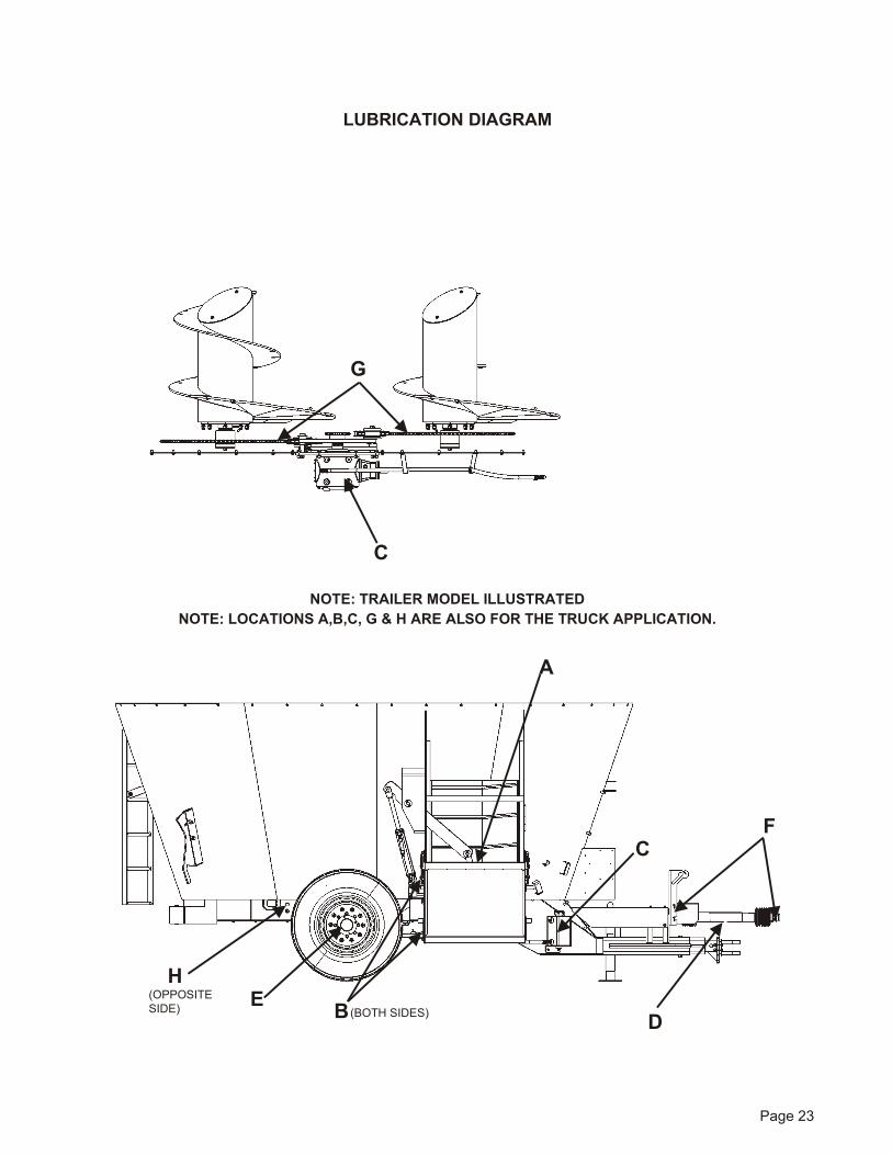
LU BRICATI ON DIAGRAM
F
D E
G
C
B
C
(BOTH SIDES)
A
H(OPPOSITESIDE)
NOTE: TRAILER MODEL IL LUS TRATEDNOTE: LO CA TIONS A,B,C, G & H ARE ALSO FOR THE TRUCK AP PLI CA TION.
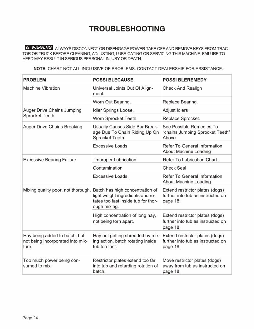
TROU BLE SHOOTING
AL WAYS DIS CON NECT OR DIS EN GAGE POWER TAKE OFF AND RE MOVE KEYS FROM TRAC -TOR OR TRUCK BE FORE CLEAN ING, AD JUST ING, LU BRI CAT ING OR SER VIC ING THIS MA CHINE. FAIL URE TOHEED MAY RE SULT IN SE RI OUS PER SONAL IN JURY OR DEATH.
NOTE: CHART NOT ALL IN CLU SIVE OF PROB LEMS. CON TACT DEAL ER SHIP FOR AS SIS TANCE.
Page 24
PROB LEM POS SI BLE CAUSE POS SI BLE REM EDY
Machine Vibration Uni ver sal Joints Out Of Align -ment.
Check And Re align
Worn Out Bear ing. Replace Bearing.
Au ger Drive Chains Jump ingSprocket Teeth
Idler Springs Loose. Adjust Idlers
Worn Sprocket Teeth. Replace Sprocket.
Au ger Drive Chains Break ing Usu ally Causes Side Bar Break -age Due To Chain Rid ing Up OnSprocket Teeth.
See Possible Remedies To“chains Jump ing Sprocket Teeth” Above
Excessive Loads Refer To General InformationAbout Ma chine Load ing
Excessive Bearing Failure Improper Lubrication Refer To Lubrication Chart.
Contamination Check Seal
Excessive Loads. Refer To General InformationAbout Ma chine Load ing
Mix ing qual ity poor, not thor ough. Batch has high con cen tra tion oflight weight in gre di ents and ro -tates too fast in side tub for thor -ough mix ing.
Ex tend restrictor plates (dogs)fur ther into tub as in structed onpage 18.
High con cen tra tion of long hay,not be ing torn apart.
Ex tend restrictor plates (dogs)fur ther into tub as in structed onpage 18.
Hay be ing added to batch, butnot being incorporated into mix -ture.
Hay not get ting shred ded by mix -ing ac tion, batch ro tat ing in side tub too fast.
Ex tend restrictor plates (dogs)fur ther into tub as in structed onpage 18.
Too much power be ing con -sumed to mix.
Restrictor plates ex tend too farinto tub and re tard ing ro ta tion ofbatch.
Move restrictor plates (dogs)away from tub as in structed onpage 18.

OP TIONAL COM PO NENT IN STAL LA TIONIN STALLING BAT TERY ON MIXER(TRAILER MOUNT ONLY)
NOTE: Trac tor socket shipped with mixer is notused when a bat tery is in stalled on the mixer.
1. Open cover on bat tery box .
2. Position 12 VDC automotiv e battery on bat -tery shelf.
3. Con nect to bat tery pos i tive and neg a tive ter -minals.
4. Con nect scale head power cord, see fig ure 2.Cord to run through side of bat tery box.
5. Use a ny lon strap to an chor bat tery to bat teryshelf (not sup plied).
6. Close cover and strap down.
SCALE MOUNT ING (TRUCK MOUNTONLY)
The pri mary scale in di ca tor is mounted to theright hand side of the driver seat on an ad just -able ped es tal. The ped es tal is cus tom fit to thetruck and is bolted to the floor of the cab andsup ported with braces to avoid vi bra tion. Theped es tal can be ad justed to pro vide easy view -ing and ac cess from the driv ers seat.
Auxiliary indicator mounts are also supplied onthe right and left hand side of the mixer to pro -vide for mount ing of an op tional Re mote In di ca -tor on ei ther or both sides of the mixer. Thesemounts al low the in di ca tor to be ro tated for easyviewing.
The Truck mixer is ini tially pro vided with mount -ing brack ets match ing the scale in di ca tor pur -chased. If in the fu ture a dif fer ent scale in di ca tor is pur chased, new mount ing brack ets will beneeded.
Page 25
FIG URE 2. AT TACH POWER CORD
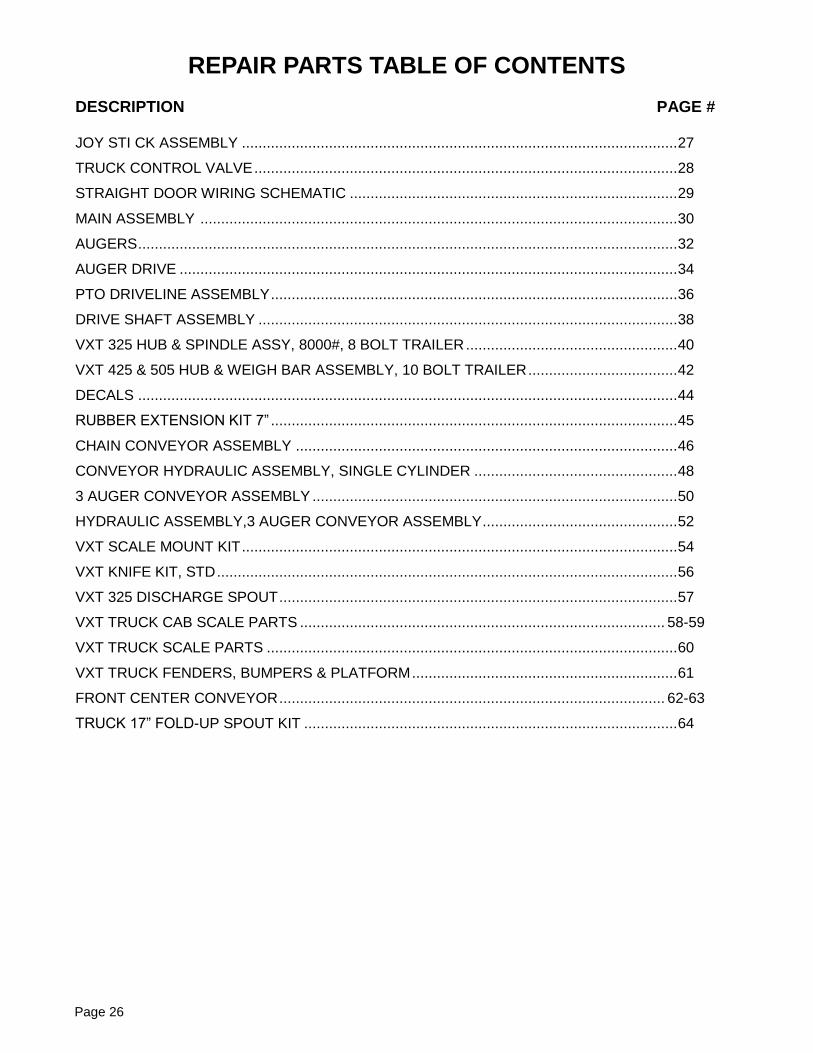
REPAIR PARTS TABLE OF CONTENTS DESCRIPTION PAGE # JOY STI CK ASSEMBLY ......................................................................................................... 27
TRUCK CONTROL VALVE ...................................................................................................... 28
STRAIGHT DOOR WIRING SCHEMATIC ............................................................................... 29
MAIN ASSEMBLY ................................................................................................................... 30
AUGERS .................................................................................................................................. 32
AUGER DRIVE ........................................................................................................................ 34
PTO DRIVELINE ASSEMBLY .................................................................................................. 36
DRIVE SHAFT ASSEMBLY ..................................................................................................... 38
VXT 325 HUB & SPINDLE ASSY, 8000#, 8 BOLT TRAILER ................................................... 40
VXT 425 & 505 HUB & WEIGH BAR ASSEMBLY, 10 BOLT TRAILER .................................... 42
DECALS .................................................................................................................................. 44
RUBBER EXTENSION KIT 7” .................................................................................................. 45
CHAIN CONVEYOR ASSEMBLY ............................................................................................ 46
CONVEYOR HYDRAULIC ASSEMBLY, SINGLE CYLINDER ................................................. 48
3 AUGER CONVEYOR ASSEMBLY ........................................................................................ 50
HYDRAULIC ASSEMBLY,3 AUGER CONVEYOR ASSEMBLY ............................................... 52
VXT SCALE MOUNT KIT ......................................................................................................... 54
VXT KNIFE KIT, STD ............................................................................................................... 56
VXT 325 DISCHARGE SPOUT ................................................................................................ 57
VXT TRUCK CAB SCALE PARTS ........................................................................................ 58-59
VXT TRUCK SCALE PARTS ................................................................................................... 60
VXT TRUCK FENDERS, BUMPERS & PLATFORM ................................................................ 61
FRONT CENTER CONVEYOR ............................................................................................. 62-63
TRUCK 17” FOLD-UP SPOUT KIT .......................................................................................... 64
Page 26
Page 27
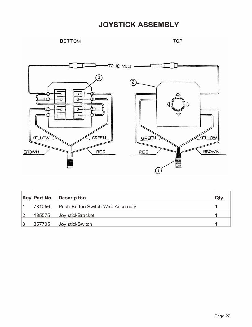
JOYSTICK ASSEMBLY
Key Part No. De scrip tion Qty.
1 781056 Push-Button Switch Wire Assembly 1
2 185575 Joy stick Bracket 1
3 357705 Joy stick Switch 1
Page 28
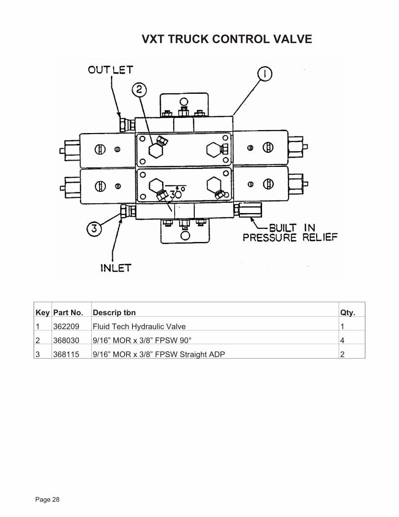
VXT TRUCK CONTROL VALVE
Key Part No. De scrip tion Qty.
1 362209 Fluid Tech Hy drau lic Valve 1
2 368030 9/16” MOR x 3/8” FPSW 90° 4
3 368115 9/16” MOR x 3/8” FPSW Straight ADP 2
Page 29
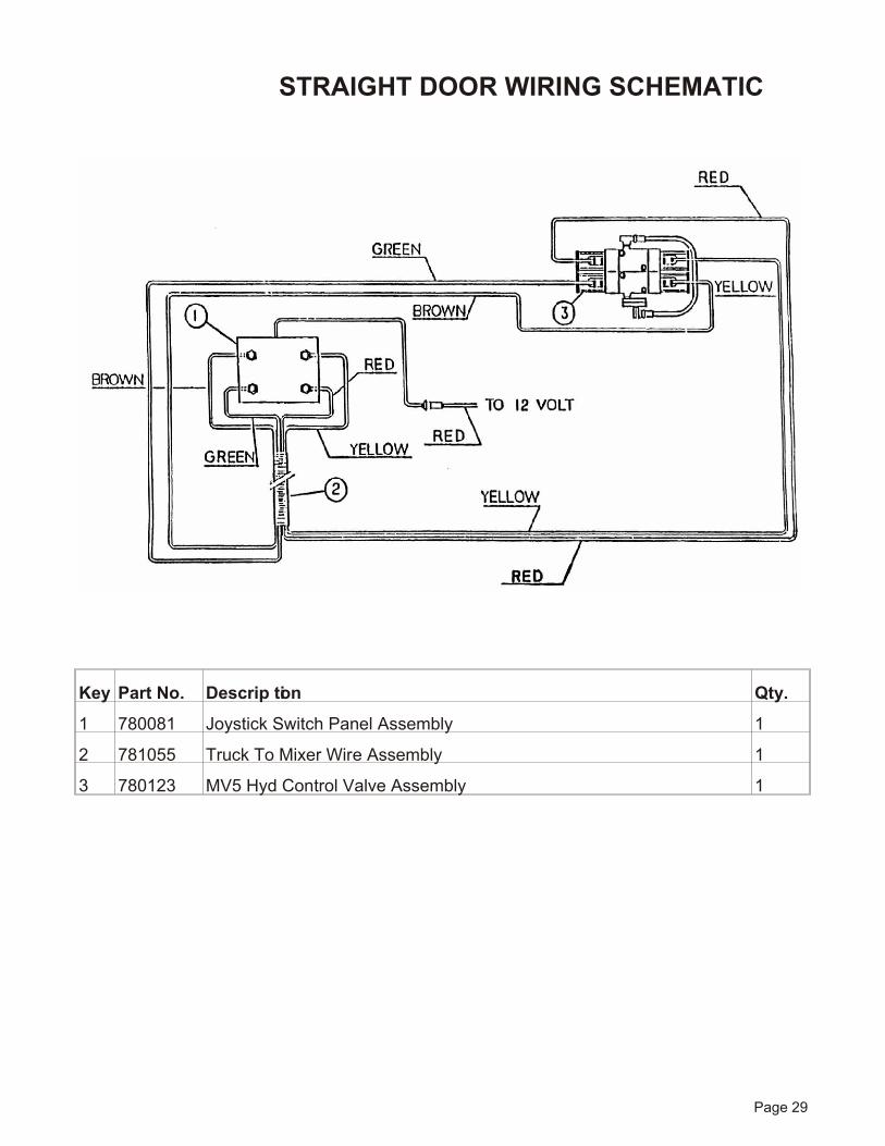
STRAIGHT DOOR WIRING SCHEMATIC
Key Part No. De scrip tion Qty.
1 780081 Joy stick Switch Panel Assembly 1
2 781055 Truck To Mixer Wire Assembly 1
3 780123 MV5 Hyd Con trol Valve Assembly 1
Page 30
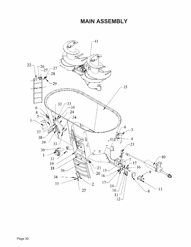
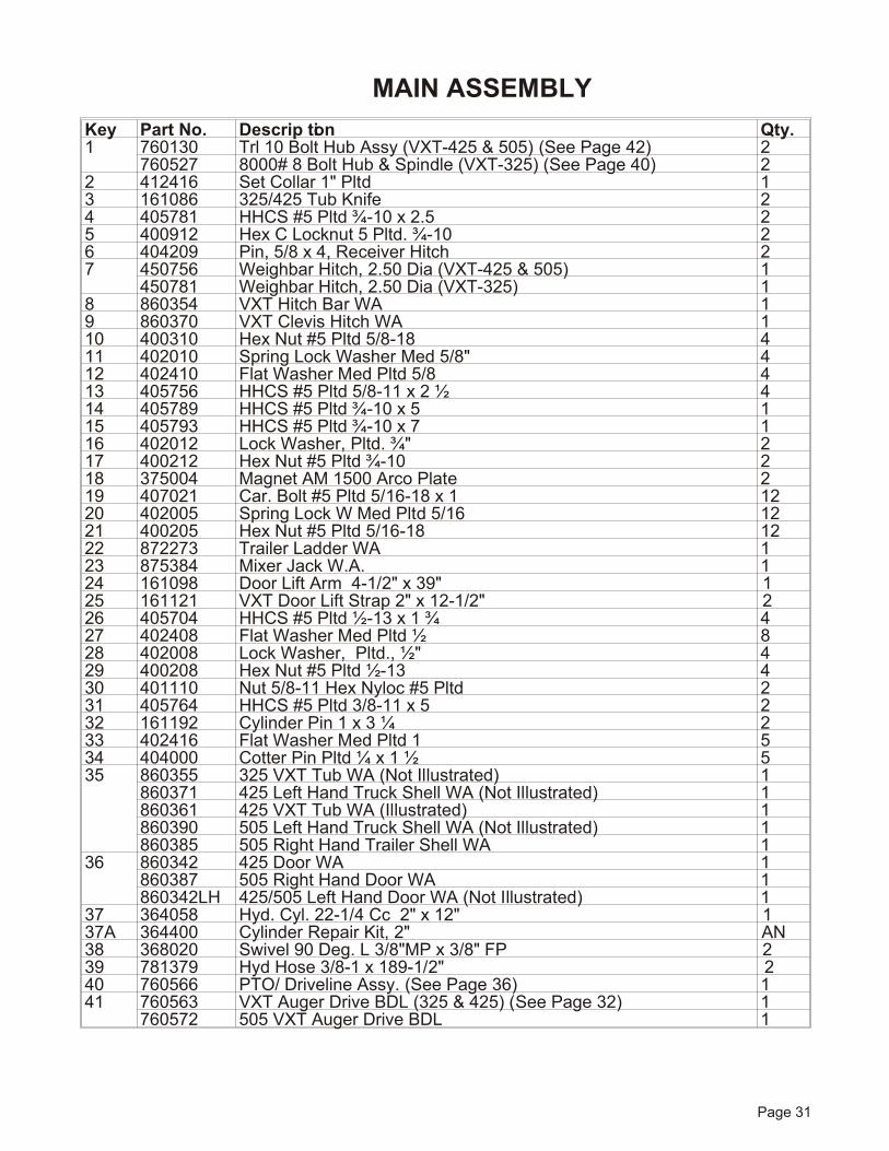
MAIN ASSEMBLY
Page 31
Key Part No. De scrip tion Qty.1 760130 Trl 10 Bolt Hub Assy (VXT-425 & 505) (See Page 42) 2
760527 8000# 8 Bolt Hub & Spin dle (VXT-325) (See Page 40) 22 412416 Set Col lar 1" Pltd 13 161086 325/425 Tub Knife 24 405781 HHCS #5 Pltd ¾-10 x 2.5 25 400912 Hex C Locknut 5 Pltd. ¾-10 26 404209 Pin, 5/8 x 4, Re ceiver Hitch 27 450756 Weighbar Hitch, 2.50 Dia (VXT-425 & 505) 1
450781 Weighbar Hitch, 2.50 Dia (VXT-325) 18 860354 VXT Hitch Bar WA 19 860370 VXT Clevis Hitch WA 110 400310 Hex Nut #5 Pltd 5/8-18 411 402010 Spring Lock Washer Med 5/8" 412 402410 Flat Washer Med Pltd 5/8 413 405756 HHCS #5 Pltd 5/8-11 x 2 ½ 414 405789 HHCS #5 Pltd ¾-10 x 5 115 405793 HHCS #5 Pltd ¾-10 x 7 116 402012 Lock Washer, Pltd. ¾" 217 400212 Hex Nut #5 Pltd ¾-10 218 375004 Mag net AM 1500 Arco Plate 219 407021 Car. Bolt #5 Pltd 5/16-18 x 1 1220 402005 Spring Lock W Med Pltd 5/16 1221 400205 Hex Nut #5 Pltd 5/16-18 1222 872273 Trailer Lad der WA 123 875384 Mixer Jack W.A. 124 161098 Door Lift Arm 4-1/2" x 39" 125 161121 VXT Door Lift Strap 2" x 12-1/2" 226 405704 HHCS #5 Pltd ½-13 x 1 ¾ 427 402408 Flat Washer Med Pltd ½ 828 402008 Lock Washer, Pltd., ½" 429 400208 Hex Nut #5 Pltd ½-13 430 401110 Nut 5/8-11 Hex Nyloc #5 Pltd 231 405764 HHCS #5 Pltd 3/8-11 x 5 232 161192 Cyl in der Pin 1 x 3 ¼ 233 402416 Flat Washer Med Pltd 1 534 404000 Cot ter Pin Pltd ¼ x 1 ½ 535 860355 325 VXT Tub WA (Not Il lus trated) 1
860371 425 Left Hand Truck Shell WA (Not Il lus trated) 1860361 425 VXT Tub WA (Il lus trated) 1860390 505 Left Hand Truck Shell WA (Not Il lus trated) 1860385 505 Right Hand Trailer Shell WA 1
36 860342 425 Door WA 1860387 505 Right Hand Door WA 1860342LH 425/505 Left Hand Door WA (Not Il lus trated) 1
37 364058 Hyd. Cyl. 22-1/4 Cc 2" x 12" 137A 364400 Cylinder Repair Kit, 2" AN38 368020 Swivel 90 Deg. L 3/8"MP x 3/8" FP 239 781379 Hyd Hose 3/8-1 x 189-1/2" 240 760566 PTO/ Driveline Assy. (See Page 36) 141 760563 VXT Au ger Drive BDL (325 & 425) (See Page 32) 1
760572 505 VXT Au ger Drive BDL 1
MAIN ASSEMBLY
Page 32
AUGERS
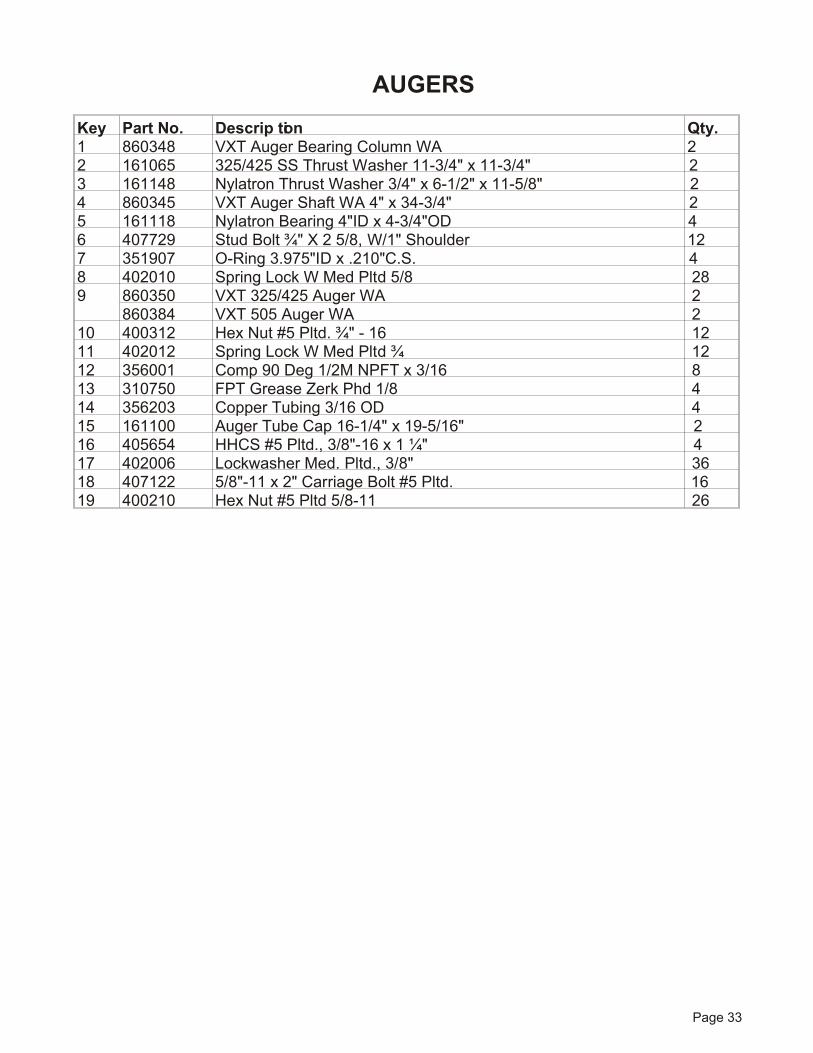
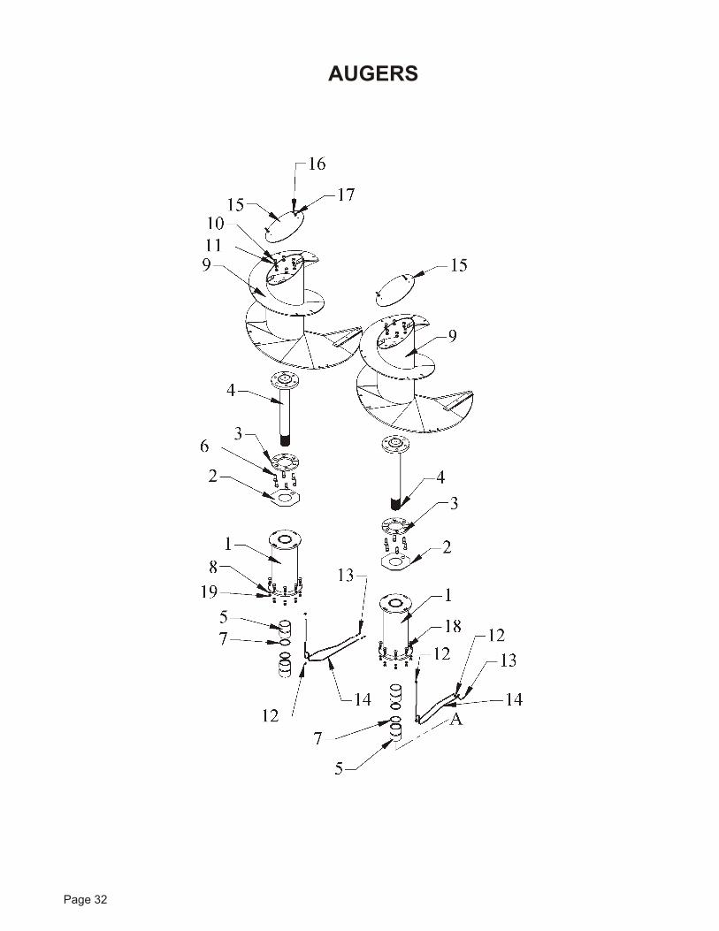
Page 33
Key Part No. De scrip tion Qty.1 860348 VXT Au ger Bear ing Col umn WA 22 161065 325/425 SS Thrust Washer 11-3/4" x 11-3/4" 23 161148 Nylatron Thrust Washer 3/4" x 6-1/2" x 11-5/8" 24 860345 VXT Au ger Shaft WA 4" x 34-3/4" 25 161118 Nylatron Bear ing 4"ID x 4-3/4"OD 46 407729 Stud Bolt ¾" X 2 5/8, W/1" Shoul der 127 351907 O-Ring 3.975"ID x .210"C.S. 48 402010 Spring Lock W Med Pltd 5/8 289 860350 VXT 325/425 Au ger WA 2
860384 VXT 505 Au ger WA 210 400312 Hex Nut #5 Pltd. ¾" - 16 1211 402012 Spring Lock W Med Pltd ¾ 1212 356001 Comp 90 Deg 1/2M NPFT x 3/16 813 310750 FPT Grease Zerk Phd 1/8 414 356203 Cop per Tubing 3/16 OD 415 161100 Au ger Tube Cap 16-1/4" x 19-5/16" 216 405654 HHCS #5 Pltd., 3/8"-16 x 1 ¼" 417 402006 Lockwasher Med. Pltd., 3/8" 3618 407122 5/8"-11 x 2" Car riage Bolt #5 Pltd. 1619 400210 Hex Nut #5 Pltd 5/8-11 26
AUGERS
Page 34
AUGERS DRIVE

Page 35
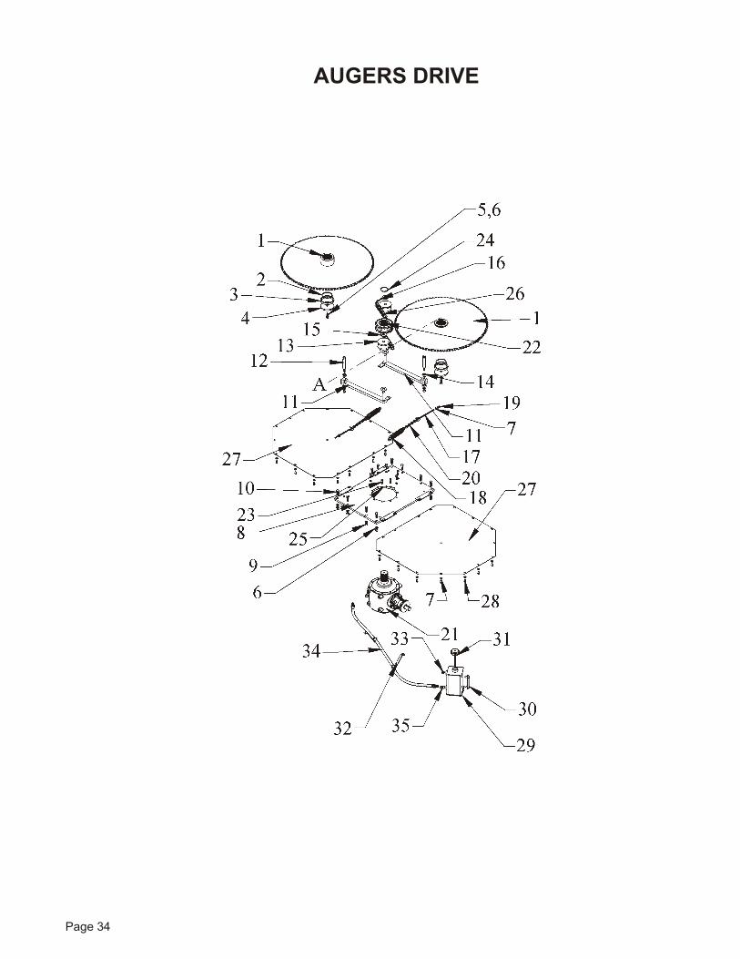
Key Part No. De scrip tion Qty.1 860359 VXT Au ger Sprocket WA 22 409962 Snap Ring 4"X.109" SH400 23 161150 VXT Re tainer Sleeve 24 185261 5 ½" O.D. Washer 25 405753 HHCS #5 Pltd. 5/8-11X1 ¾ 26 402010 Spring Lock W Med Pltd 5/8 287 402406 Flat Washer, 3/8" ID X 1" OD 368 860340 VXT Gear box Mnt WA 19 400210 Hex Nut #5 Pltd 5/8-11 2610 405754 HHCS #5 Pltd., 5/8"-11 X 2" 811 860357 Idler Arm WA 1" X 2" X 21" 212 161170 325/425 Idler Pin 1" X 7-3/8" 213 161165 Idler Block 5" OD UHMW 214 412416 Set Col lar 1" Pltd 415 402416 Flat Washer Med Pltd 1 416 404001 5/32" Cot ter Pin X 1 ¼" 217 410852 3/8" X 8" Eye Bolt 218 410012 Spring Pull 1 ¾" X 7 X .218 219 400206 Hex Nut #5 Pltd 3/8-16 620 170323 Chain-14 Links 221 344071 GB,Rt Agl,1.75"In,3"SPL Out 122 860358 VXT Gear box Sprocket WA 123 407819 M12-1.75 x 45mm HHCS 10.9 824 409961 Snap Ring 3” x .093 SH300 125 402008 Spring Lock W Med Pltd ½ 826 321118 Pitch - Com plete #100 RC x 118P 227 161077 325/425 Chain Drive Door 43-1/4"X45-5/16" 228 405653 3/8" -16 X 1" #5 Pltd HHCS 3229 875416 Gearbox Reservoir WA 6 x 6 x 10 130 362555 5" Sight Gauge 131 362549 Tank Breather NBF-2016 8" Dip Stick 132 860369 VXT GB Tube Hanger WA 233 310702 ½" Pipe Plug 234 781512 1/2x76” Hyd Hose 1/2MP x 1/2MP 135 368111 Str. Adp. ½" X ½" FP Swivel 1
AUGERS DRIVE
Page 36
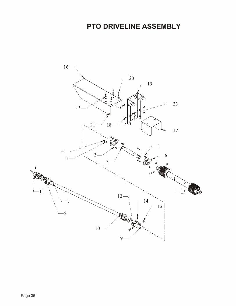
PTO DRIVELINE ASSEMBLY
Page 37
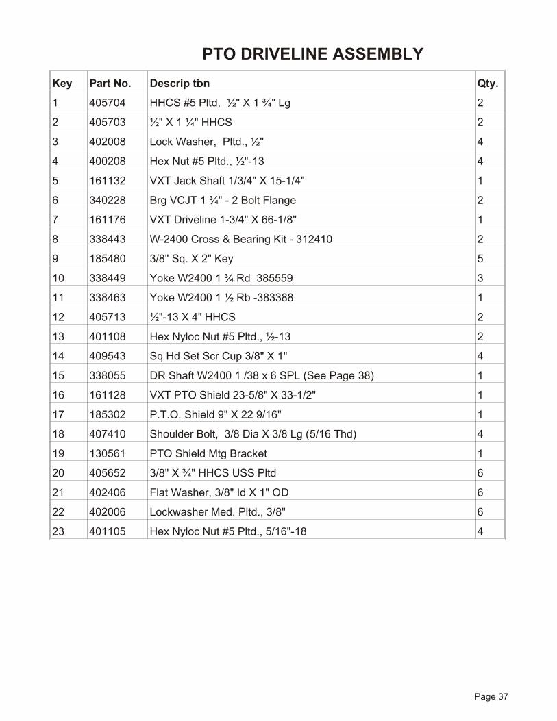
Key Part No. De scrip tion Qty.
1 405704 HHCS #5 Pltd, ½" X 1 ¾" Lg 2
2 405703 ½" X 1 ¼" HHCS 2
3 402008 Lock Washer, Pltd., ½" 4
4 400208 Hex Nut #5 Pltd., ½"-13 4
5 161132 VXT Jack Shaft 1/3/4" X 15-1/4" 1
6 340228 Brg VCJT 1 ¾" - 2 Bolt Flange 2
7 161176 VXT Driveline 1-3/4" X 66-1/8" 1
8 338443 W-2400 Cross & Bearing Kit - 312410 2
9 185480 3/8" Sq. X 2" Key 5
10 338449 Yoke W2400 1 ¾ Rd 385559 3
11 338463 Yoke W2400 1 ½ Rb -383388 1
12 405713 ½"-13 X 4" HHCS 2
13 401108 Hex Nyloc Nut #5 Pltd., ½-13 2
14 409543 Sq Hd Set Scr Cup 3/8" X 1" 4
15 338055 DR Shaft W2400 1 /38 x 6 SPL (See Page 38) 1
16 161128 VXT PTO Shield 23-5/8" X 33-1/2" 1
17 185302 P.T.O. Shield 9" X 22 9/16" 1
18 407410 Shoulder Bolt, 3/8 Dia X 3/8 Lg (5/16 Thd) 4
19 130561 PTO Shield Mtg Bracket 1
20 405652 3/8" X ¾" HHCS USS Pltd 6
21 402406 Flat Washer, 3/8" Id X 1" OD 6
22 402006 Lockwasher Med. Pltd., 3/8" 6
23 401105 Hex Nyloc Nut #5 Pltd., 5/16"-18 4
PTO DRIVELINE ASSEMBLY
2 1 3 5 8 12 10
15 14
671413911
7
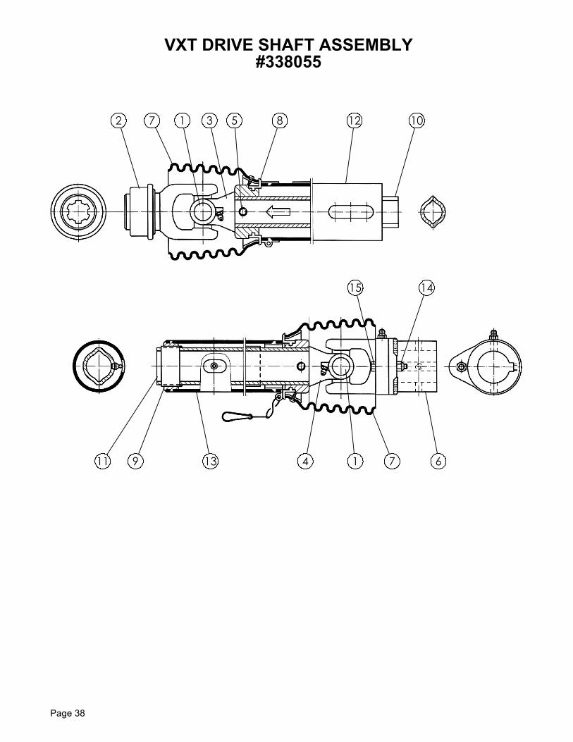
VXT DRIVE SHAFT ASSEMBLY#338055
Page 38
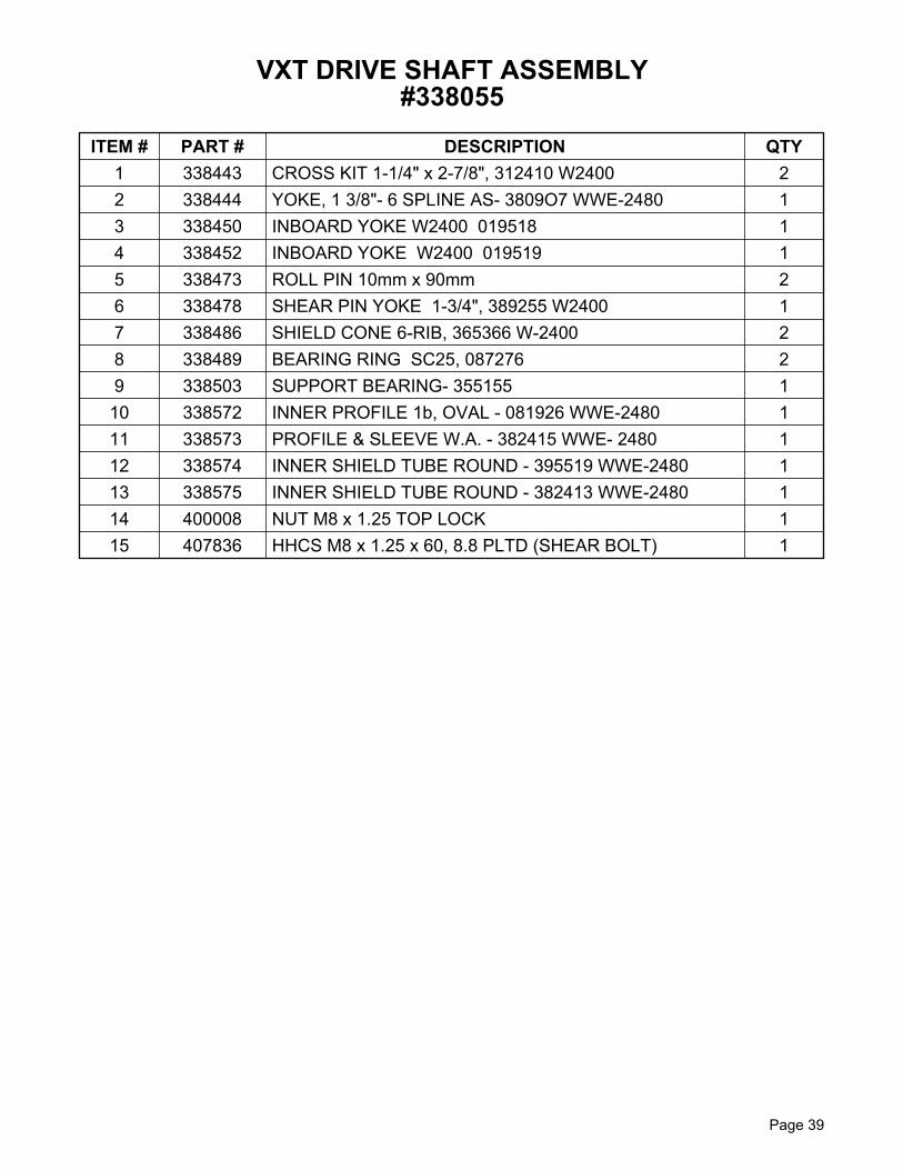
ITEM # PART # DESCRIPTION QTY 1 338443 CROSS KIT 1-1/4" x 2-7/8", 312410 W2400 22 338444 YOKE, 1 3/8"- 6 SPLINE AS- 3809O7 WWE-2480 13 338450 INBOARD YOKE W2400 019518 14 338452 INBOARD YOKE W2400 019519 15 338473 ROLL PIN 10mm x 90mm 26 338478 SHEAR PIN YOKE 1-3/4", 389255 W2400 17 338486 SHIELD CONE 6-RIB, 365366 W-2400 28 338489 BEARING RING SC25, 087276 29 338503 SUPPORT BEARING- 355155 1
10 338572 INNER PROFILE 1b, OVAL - 081926 WWE-2480 111 338573 PROFILE & SLEEVE W.A. - 382415 WWE- 2480 112 338574 INNER SHIELD TUBE ROUND - 395519 WWE-2480 113 338575 INNER SHIELD TUBE ROUND - 382413 WWE-2480 114 400008 NUT M8 x 1.25 TOP LOCK 115 407836 HHCS M8 x 1.25 x 60, 8.8 PLTD (SHEAR BOLT) 1
Page 39
VXT DRIVE SHAFT ASSEMBLY#338055
Page 40
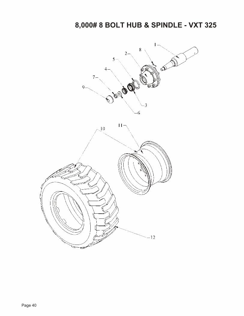
8,000# 8 BOLT HUB & SPINDLE - VXT 325
Page 41
KEY PART NO. DE SCRIP TION QTY.1 450780 Weighbar Axle, 2.875 Dia 12 372207A Hub 8 Bolt 8000LB 13 342205 Brg. 2.25 Bore 14 342206 Brg. 1.625 Bore 15 355066 Seal 4" OD x 2 7/8" ID x x7/16W 16 402910 Washer, 2.13ID x 1.06OD x .26Thk 17 401816 1 ¼" Hex Cas tle Nut 18 404006 5/32" Cot ter Pin x 1 ¼" 19 372307 Dust Cap Wil ton 110 780754-R 33 x 16.5 Wheel & Tire W/Lug Tread - Right Hand 110A 780754-L 33 x 16.5 Wheel & Tire W/Lug Tread - Left Hand 111 372437 Wheel, 12” W x 16.50” DIA, 8 Bolt 112 372637 Tire, 33” x 15.5” x 16.5”, Off Road Tread 1
8,000# 8 BOLT HUB & SPINDLE - VXT 325
Page 42
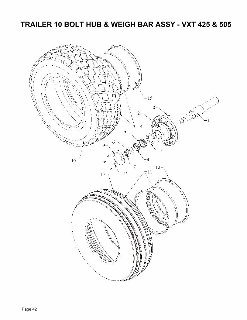
TRAILER 10 BOLT HUB & WEIGH BAR ASSY - VXT 425 & 505
Page 43
KEY PART NO. DE SCRIP TION QTY.1 450711 Axle Bar Cell, 2 7/8 12K Hub 12 372209A Hub 10 Bolt 12000LB 13 342209 Brg. 2.5 Bore 14 342210 Brg. 1.75 Bore 15 372321 Seal 2 7/8" Bore x 4 ½" OD 16 402911 Washer, 1.22ID x 3.25OD x .19Thk 17 401820 1 ¼-12 Hex Cas tle Nut SAE Pltd 18 404003 Cot ter Pin 5/32 x 1 ¼ 19 372308 Dust Cap Wil ton #9099831 110 405625 HHCS #5 Pltd 5/16 x ½ 411 781466 Wheel & Tire 40x14.5x19 Re cap Air craft 112 W159365 Wheel 19x11-10 Bolt, Bolt To gether 113 W158677 Tire H40x14.5x19 Re cap Air craft 1NS W160833 In ner Tube H40x14.5x19 1NS W160868 Flap H40x14.5x19 114 781209 15x22.5 Tire & Wheel Assy. (Op tion) 115 372422 15x22.5 10 Bolt Wheel 116 372614 Tire Lug Tread 15x22.5 1
TRAILER 10 BOLT HUB & WEIGH BAR ASSY - VXT 425 & 505
Page 44
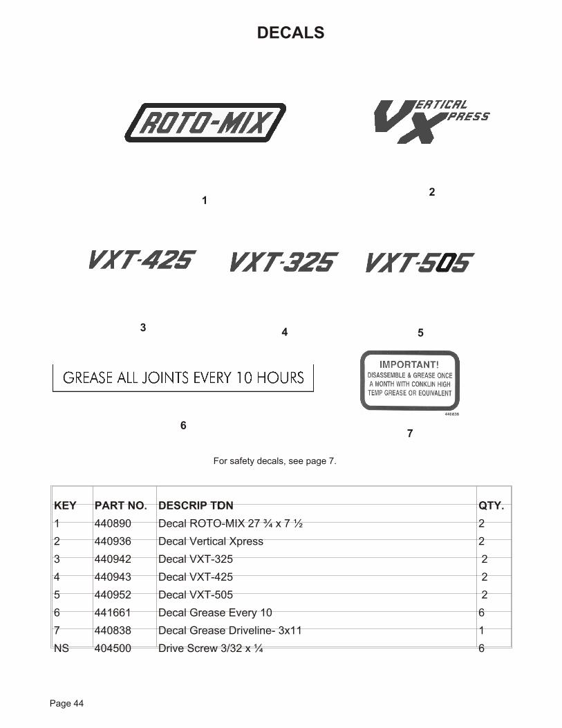
DECALS
For safety de cals, see page 7.
1
43
2
67
KEY PART NO. DE SCRIP TION QTY.1 440890 De cal ROTO-MIX 27 ¾ x 7 ½ 22 440936 Decal Vertical Xpress 23 440942 Decal VXT-325 24 440943 Decal VXT-425 25 440952 Decal VXT-505 26 441661 De cal Grease Ev ery 10 67 440838 De cal Grease Driveline- 3x11 1NS 404500 Drive Screw 3/32 x ¼ 6
5
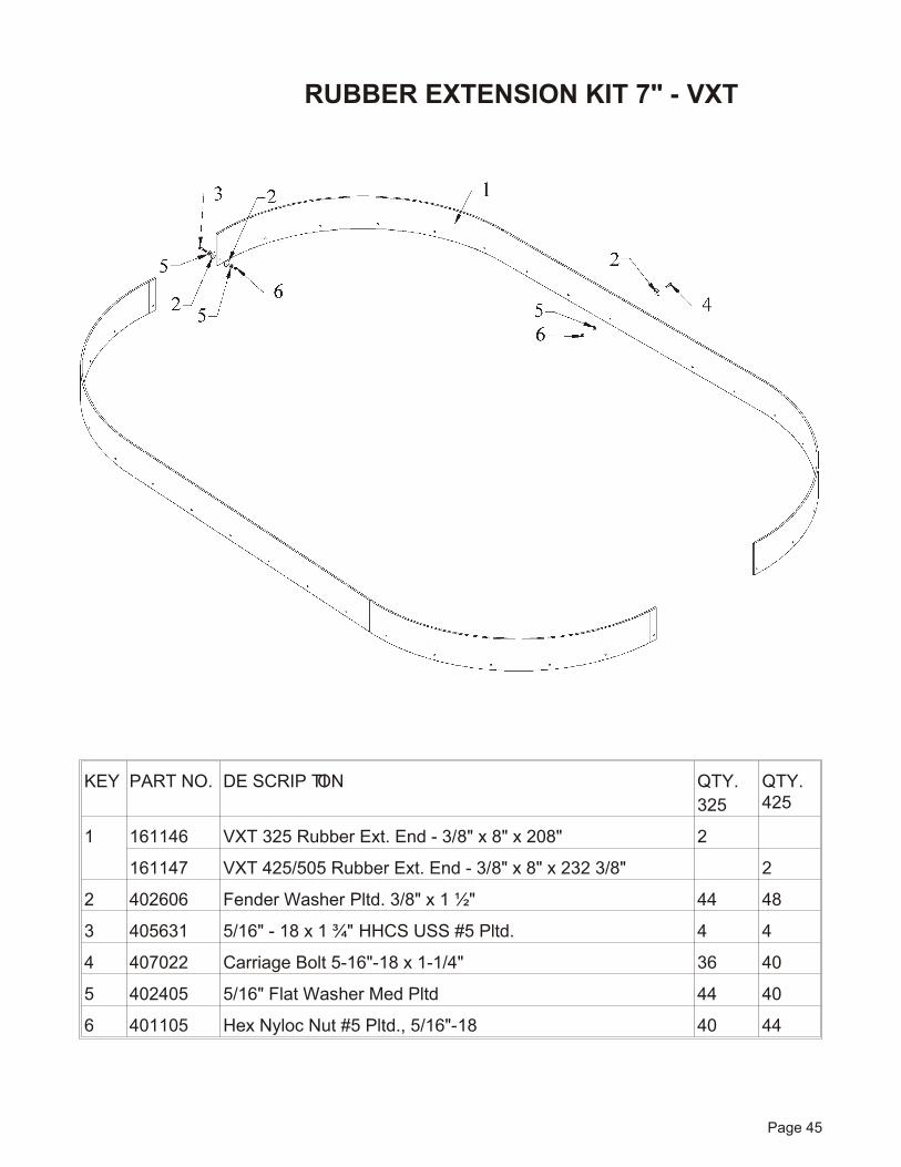
KEY PART NO. DE SCRIP TION QTY.325
QTY.425
1 161146 VXT 325 Rub ber Ext. End - 3/8" x 8" x 208" 2
161147 VXT 425/505 Rub ber Ext. End - 3/8" x 8" x 232 3/8" 2
2 402606 Fender Washer Pltd. 3/8" x 1 ½" 44 48
3 405631 5/16" - 18 x 1 ¾" HHCS USS #5 Pltd. 4 4
4 407022 Car riage Bolt 5-16"-18 x 1-1/4" 36 40
5 402405 5/16" Flat Washer Med Pltd 44 40
6 401105 Hex Nyloc Nut #5 Pltd., 5/16"-18 40 44
Page 45
RUBBER EXTENSION KIT 7" - VXT
3
22
2
21
19
4
20
8
1
12 141817
120
1615137
1414
6
11
19
5
10
19
9
23
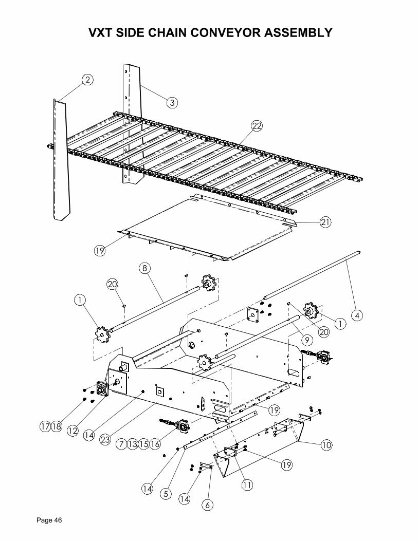
VXT SIDE CHAIN CONVEYOR ASSEMBLY
Page 46
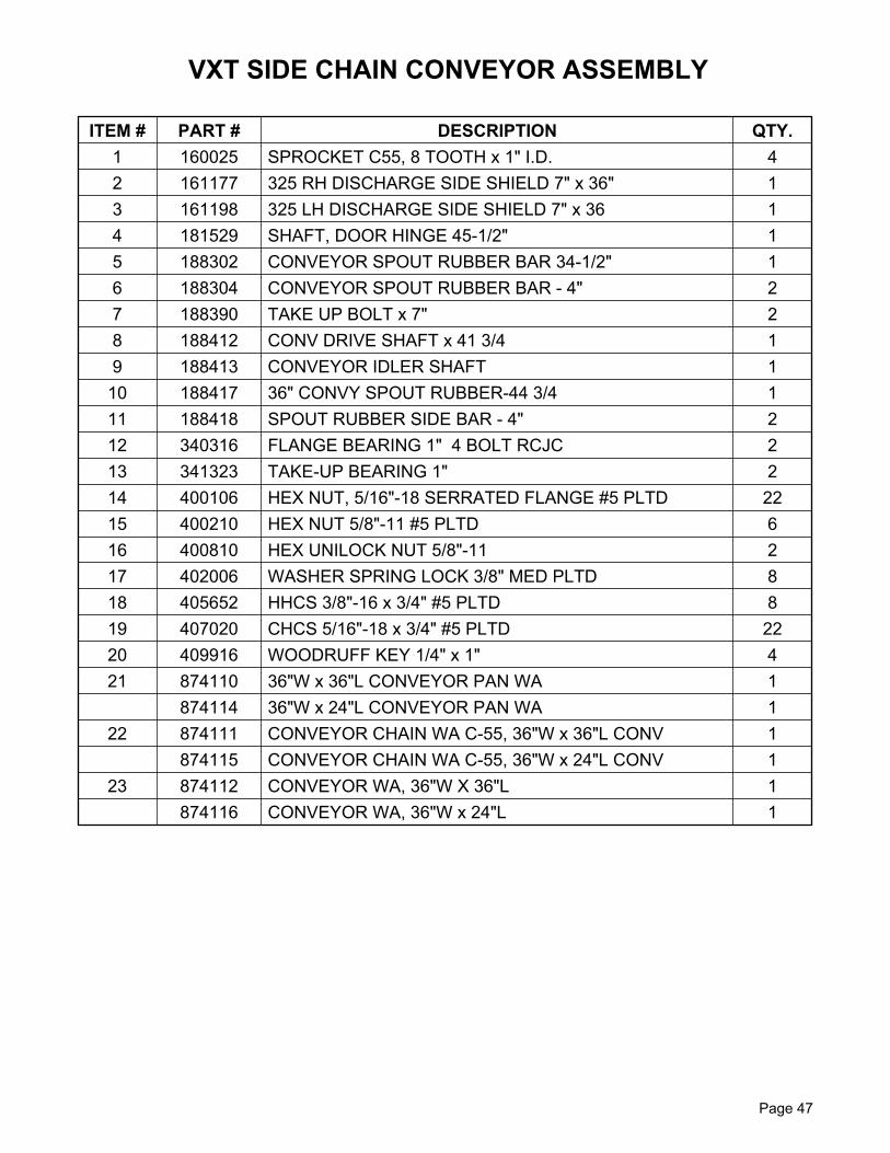
ITEM # PART # DESCRIPTION QTY. 1 160025 SPROCKET C55, 8 TOOTH x 1" I.D. 42 161177 325 RH DISCHARGE SIDE SHIELD 7" x 36" 13 161198 325 LH DISCHARGE SIDE SHIELD 7" x 36 14 181529 SHAFT, DOOR HINGE 45-1/2" 15 188302 CONVEYOR SPOUT RUBBER BAR 34-1/2" 16 188304 CONVEYOR SPOUT RUBBER BAR - 4" 27 188390 TAKE UP BOLT x 7" 28 188412 CONV DRIVE SHAFT x 41 3/4 19 188413 CONVEYOR IDLER SHAFT 1
10 188417 36" CONVY SPOUT RUBBER-44 3/4 111 188418 SPOUT RUBBER SIDE BAR - 4" 212 340316 FLANGE BEARING 1" 4 BOLT RCJC 213 341323 TAKE-UP BEARING 1" 214 400106 HEX NUT, 5/16"-18 SERRATED FLANGE #5 PLTD 2215 400210 HEX NUT 5/8"-11 #5 PLTD 616 400810 HEX UNILOCK NUT 5/8"-11 217 402006 WASHER SPRING LOCK 3/8" MED PLTD 818 405652 HHCS 3/8"-16 x 3/4" #5 PLTD 819 407020 CHCS 5/16"-18 x 3/4" #5 PLTD 2220 409916 WOODRUFF KEY 1/4" x 1" 421 874110 36"W x 36"L CONVEYOR PAN WA 1
874114 36"W x 24"L CONVEYOR PAN WA 122 874111 CONVEYOR CHAIN WA C-55, 36"W x 36"L CONV 1
874115 CONVEYOR CHAIN WA C-55, 36"W x 24"L CONV 123 874112 CONVEYOR WA, 36"W X 36"L 1
874116 CONVEYOR WA, 36"W x 24"L 1
VXT SIDE CHAIN CONVEYOR ASSEMBLY
Page 47
Page 48
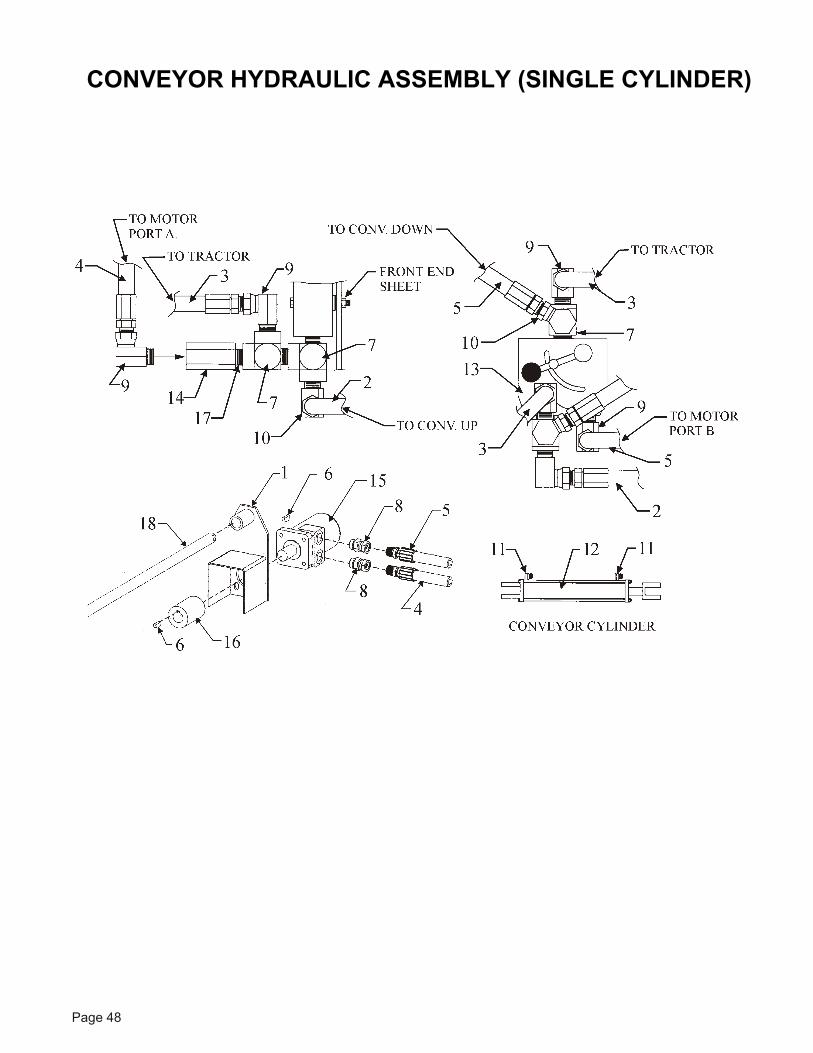
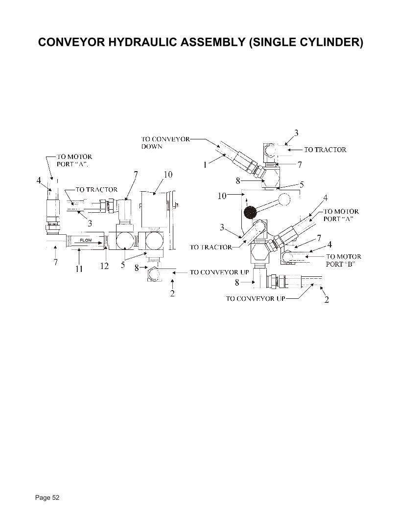
CONVEYOR HYDRAULIC ASSEMBLY (SINGLE CYLINDER)
Page 49
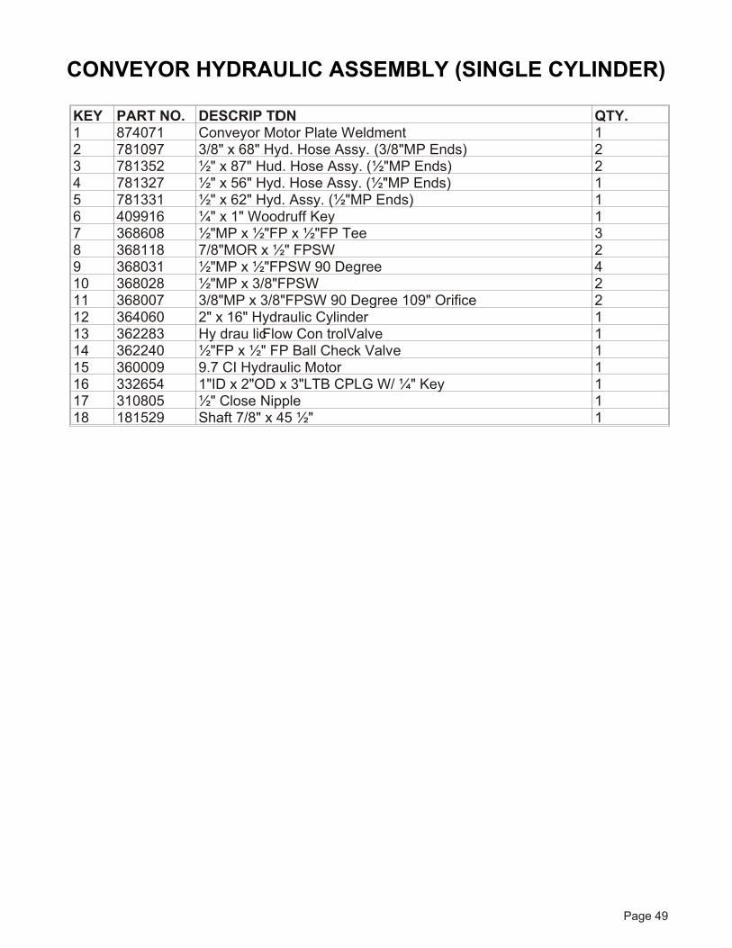
KEY PART NO. DE SCRIP TION QTY.1 874071 Con veyor Mo tor Plate Weldment 12 781097 3/8" x 68" Hyd. Hose Assy. (3/8"MP Ends) 23 781352 ½" x 87" Hud. Hose Assy. (½"MP Ends) 24 781327 ½" x 56" Hyd. Hose Assy. (½"MP Ends) 15 781331 ½" x 62" Hyd. Assy. (½"MP Ends) 16 409916 ¼" x 1" Wood ruff Key 17 368608 ½"MP x ½"FP x ½"FP Tee 38 368118 7/8"MOR x ½" FPSW 29 368031 ½"MP x ½"FPSW 90 De gree 410 368028 ½"MP x 3/8"FPSW 211 368007 3/8"MP x 3/8"FPSW 90 De gree 109" Or i fice 212 364060 2" x 16" Hy drau lic Cyl in der 113 362283 Hy drau lic Flow Con trol Valve 114 362240 ½"FP x ½" FP Ball Check Valve 115 360009 9.7 CI Hy drau lic Mo tor 116 332654 1"ID x 2"OD x 3"LTB CPLG W/ ¼" Key 117 310805 ½" Close Nip ple 118 181529 Shaft 7/8" x 45 ½" 1
CONVEYOR HYDRAULIC ASSEMBLY (SINGLE CYLINDER)
Page 50
3 AUGER CONVEYOR ASSEMBLY
Page 51
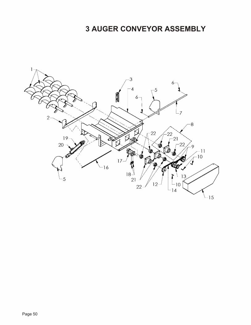
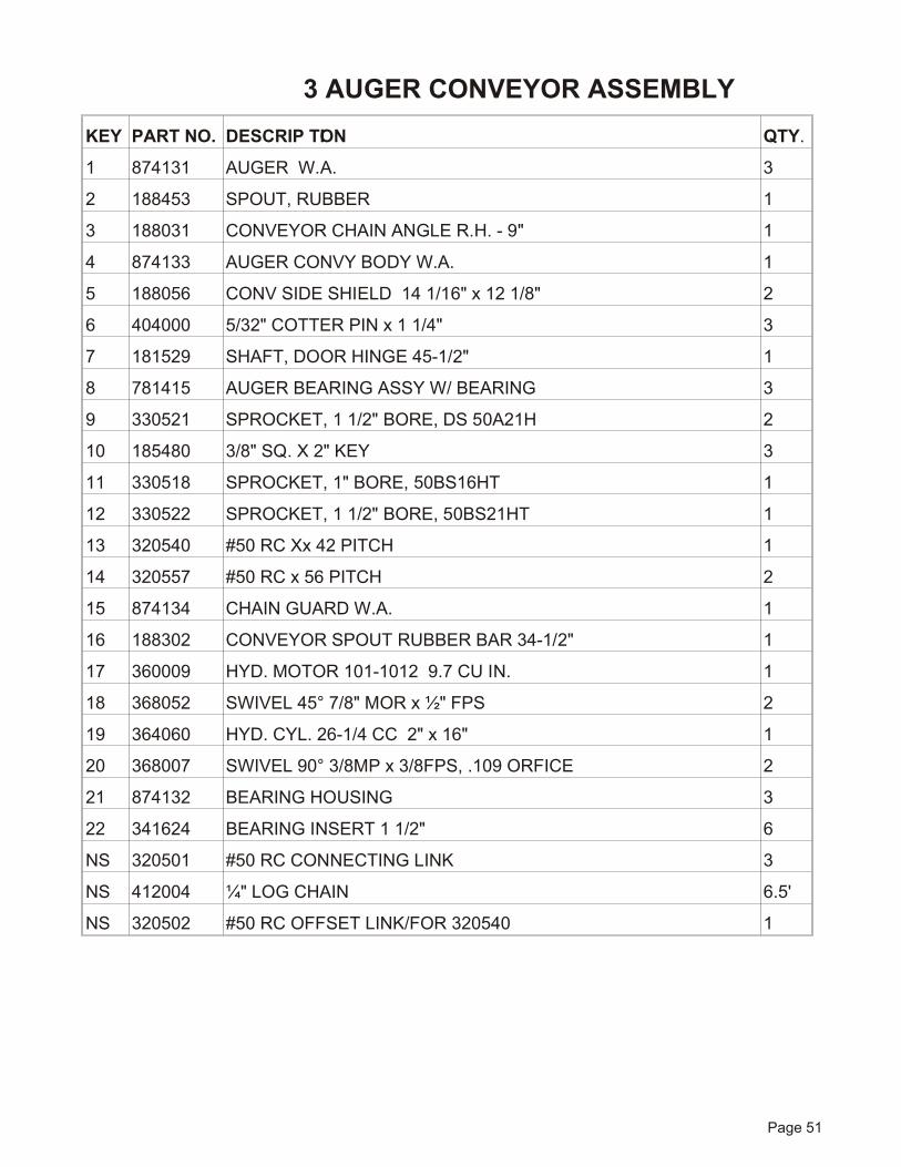
KEY PART NO. DE SCRIP TION QTY.
1 874131 AU GER W.A. 3
2 188453 SPOUT, RUBBER 1
3 188031 CON VEYOR CHAIN AN GLE R.H. - 9" 1
4 874133 AU GER CONVY BODY W.A. 1
5 188056 CONV SIDE SHIELD 14 1/16" x 12 1/8" 2
6 404000 5/32" COT TER PIN x 1 1/4" 3
7 181529 SHAFT, DOOR HINGE 45-1/2" 1
8 781415 AU GER BEAR ING ASSY W/ BEARING 3
9 330521 SPROCKET, 1 1/2" BORE, DS 50A21H 2
10 185480 3/8" SQ. X 2" KEY 3
11 330518 SPROCKET, 1" BORE, 50BS16HT 1
12 330522 SPROCKET, 1 1/2" BORE, 50BS21HT 1
13 320540 #50 RC Xx 42 PITCH 1
14 320557 #50 RC x 56 PITCH 2
15 874134 CHAIN GUARD W.A. 1
16 188302 CON VEYOR SPOUT RUB BER BAR 34-1/2" 1
17 360009 HYD. MO TOR 101-1012 9.7 CU IN. 1
18 368052 SWIVEL 45° 7/8" MOR x ½" FPS 2
19 364060 HYD. CYL. 26-1/4 CC 2" x 16" 1
20 368007 SWIVEL 90° 3/8MP x 3/8FPS, .109 ORFICE 2
21 874132 BEARING HOUSING 3
22 341624 BEAR ING IN SERT 1 1/2" 6
NS 320501 #50 RC CON NECT ING LINK 3
NS 412004 ¼" LOG CHAIN 6.5'
NS 320502 #50 RC OFF SET LINK/FOR 320540 1
3 AUGER CONVEYOR ASSEMBLY
Page 52
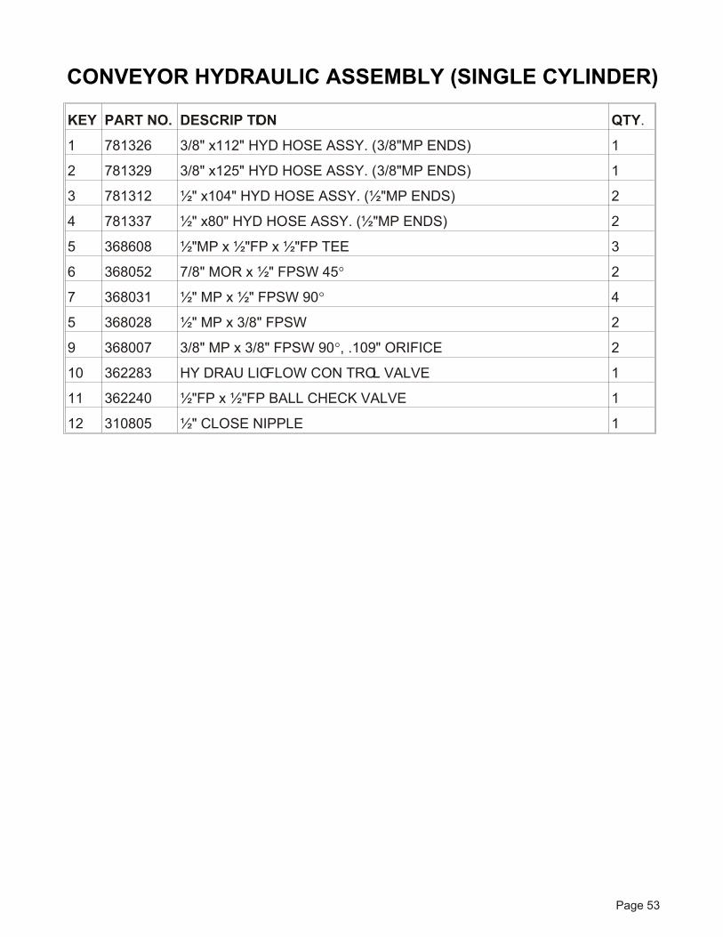
CONVEYOR HYDRAULIC ASSEMBLY (SINGLE CYLINDER)
Page 53
KEY PART NO. DE SCRIP TION QTY.
1 781326 3/8" x112" HYD HOSE ASSY. (3/8"MP ENDS) 1
2 781329 3/8" x125" HYD HOSE ASSY. (3/8"MP ENDS) 1
3 781312 ½" x104" HYD HOSE ASSY. (½"MP ENDS) 2
4 781337 ½" x80" HYD HOSE ASSY. (½"MP ENDS) 2
5 368608 ½"MP x ½"FP x ½"FP TEE 3
6 368052 7/8" MOR x ½" FPSW 45° 2
7 368031 ½" MP x ½" FPSW 90° 4
5 368028 ½" MP x 3/8" FPSW 2
9 368007 3/8" MP x 3/8" FPSW 90°, .109" ORIFICE 2
10 362283 HY DRAU LIC FLOW CON TROL VALVE 1
11 362240 ½"FP x ½"FP BALL CHECK VALVE 1
12 310805 ½" CLOSE NIPPLE 1
CONVEYOR HYDRAULIC ASSEMBLY (SINGLE CYLINDER)
Page 54
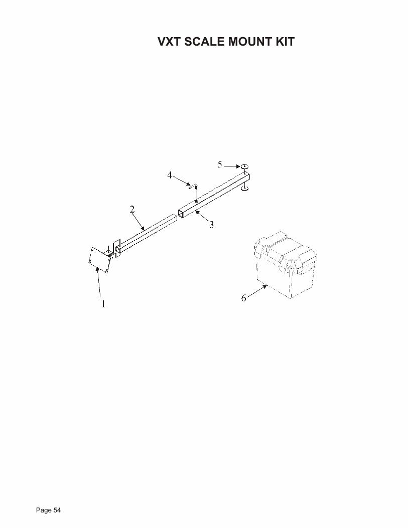
VXT SCALE MOUNT KIT
Page 55
KEY PART NO. DE SCRIP TION QTY.
1 872126 Trl Scale Ind Arm WA-2Sq X 1
2 185490 Tube, Trl Scale In di ca tor, 29 1
3 872125 Trl Scale Arm WA-2 1/2Sq X 1
4 185492 Han dle, ½" Lock ing, 6 1
5 185493 Washer, Scale Hinge, 2 ½ OD 2
6 357400 Bat tery Box W/Strap 7.5 x 11 1
NS 450923 J-Box (141879 J-Star 15') 1
NS 455407 Bat tery Clamp, Law son 45804 1
NS 455406 Bat tery Clamp, Law son 45803 1
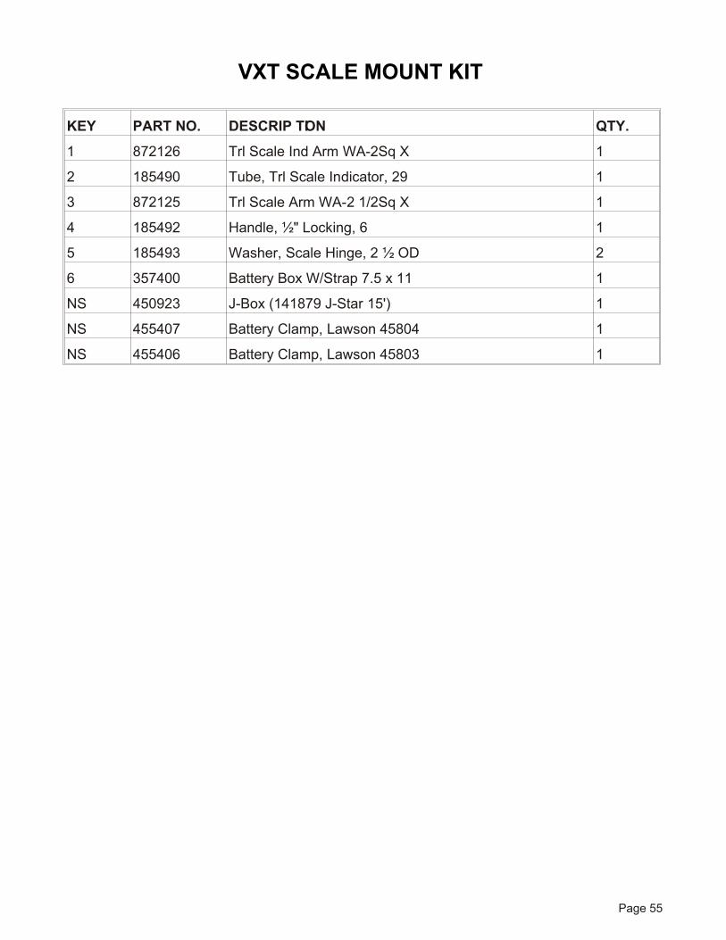
VXT SCALE MOUNT KIT

KEY PART NO. DE SCRIP TION QTY.
1 385012 Knife Blade- ½" Curved 3
2 407121 Car Bolt #5 Pltd 5/8-11 x 2 6
3 400115 Flange Nut, 5/8-11 Ser rated 6
4 385009 Blade RH Aug Knife- 3 ½ x 8" 2
5 407102 Carg Bolt #5 Pltd ½ x 1 ½ 4
6 400114 Flange Nut, ½-13 Ser rated 4
Page 56
VXT KNIFE KIT - STD
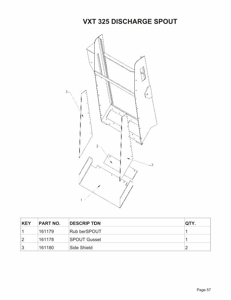
KEY PART NO. DE SCRIP TION QTY.
1 161179 Rub ber SPOUT 1
2 161178 SPOUT Gus set 1
3 161180 Side Shield 2
Page 57
VXT 325 DISCHARGE SPOUT
Page 58
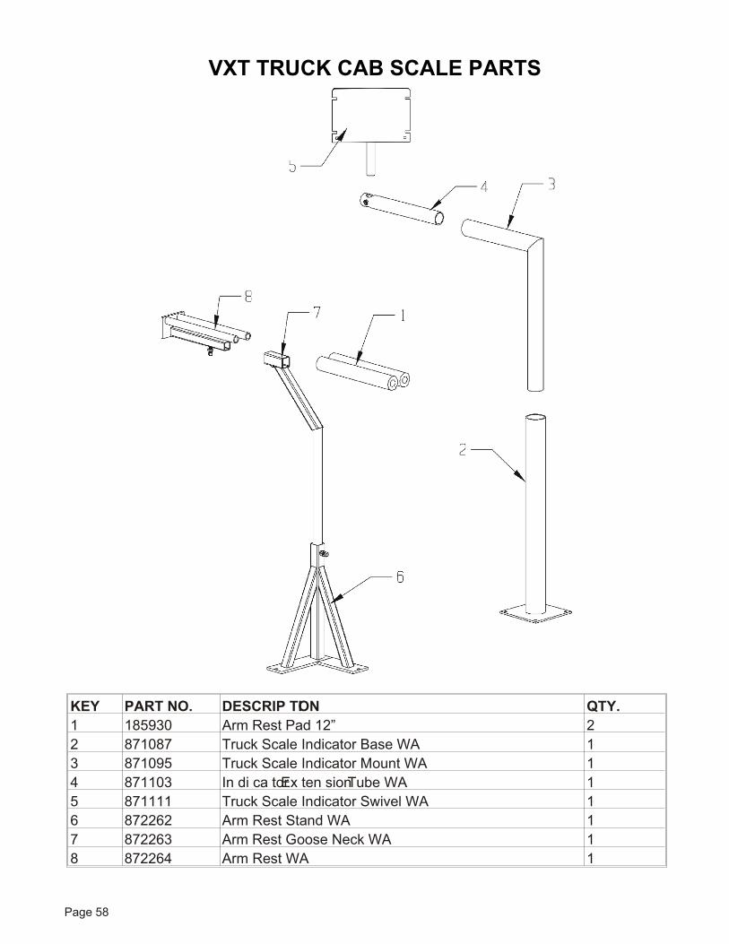
KEY PART NO. DE SCRIP TION QTY.1 185930 Arm Rest Pad 12” 22 871087 Truck Scale In di ca tor Base WA 13 871095 Truck Scale In di ca tor Mount WA 14 871103 In di ca tor Ex ten sion Tube WA 15 871111 Truck Scale In di ca tor Swivel WA 16 872262 Arm Rest Stand WA 17 872263 Arm Rest Goose Neck WA 18 872264 Arm Rest WA 1
VXT TRUCK CAB SCALE PARTS
8
15
14
17
816
8
19
18
5
9
1111
310
6
2
4
2120
13
1
7 12
7 12
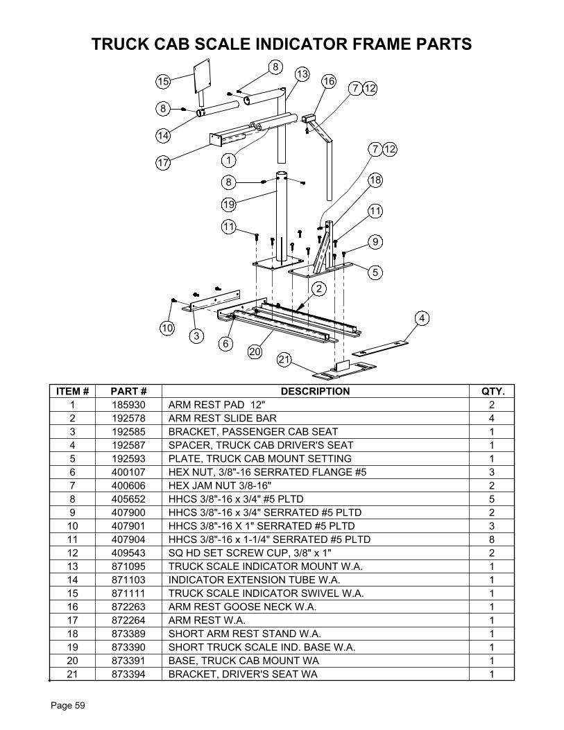
ITEM # PART # DESCRIPTION QTY.1 185930 ARM REST PAD 12" 22 192578 ARM REST SLIDE BAR 43 192585 BRACKET, PASSENGER CAB SEAT 14 192587 SPACER, TRUCK CAB DRIVER'S SEAT 15 192593 PLATE, TRUCK CAB MOUNT SETTING 16 400107 HEX NUT, 3/8"-16 SERRATED FLANGE #5 37 400606 HEX JAM NUT 3/8-16" 28 405652 HHCS 3/8"-16 x 3/4" #5 PLTD 59 407900 HHCS 3/8"-16 x 3/4" SERRATED #5 PLTD 2
10 407901 HHCS 3/8"-16 X 1" SERRATED #5 PLTD 311 407904 HHCS 3/8"-16 x 1-1/4" SERRATED #5 PLTD 812 409543 SQ HD SET SCREW CUP, 3/8" x 1" 213 871095 TRUCK SCALE INDICATOR MOUNT W.A. 114 871103 INDICATOR EXTENSION TUBE W.A. 115 871111 TRUCK SCALE INDICATOR SWIVEL W.A. 116 872263 ARM REST GOOSE NECK W.A. 117 872264 ARM REST W.A. 118 873389 SHORT ARM REST STAND W.A. 119 873390 SHORT TRUCK SCALE IND. BASE W.A. 120 873391 BASE, TRUCK CAB MOUNT WA 121 873394 BRACKET, DRIVER'S SEAT WA 1
TRUCK CAB SCALE INDICATOR FRAME PARTS
Page 59
Page 59
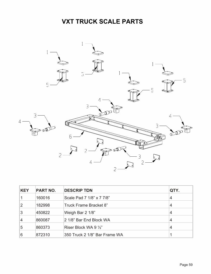
KEY PART NO. DE SCRIP TION QTY.
1 160016 Scale Pad 7 1/8” x 7 7/8” 4
2 182998 Truck Frame Bracket 8” 4
3 450822 Weigh Bar 2 1/8” 4
4 860087 2 1/8” Bar End Block WA 4
5 860373 Riser Block WA 9 ½” 4
6 872310 350 Truck 2 1/8” Bar Frame WA 1
VXT TRUCK SCALE PARTS
Page 60
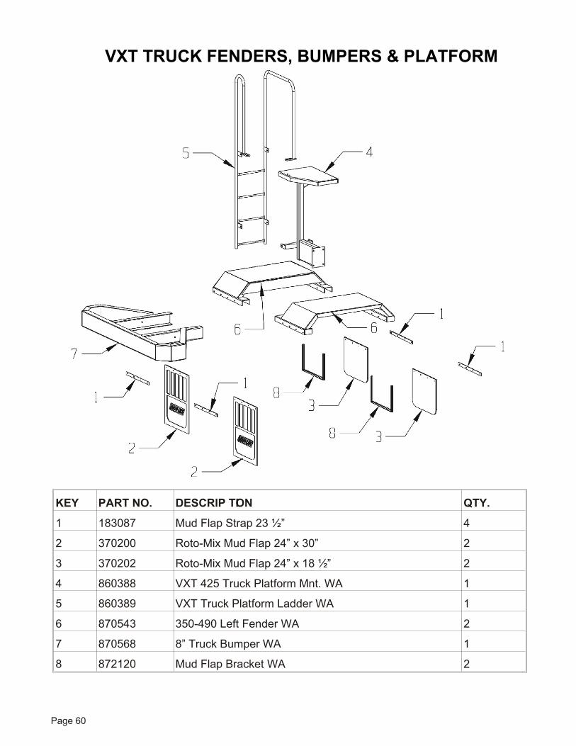
KEY PART NO. DE SCRIP TION QTY.
1 183087 Mud Flap Strap 23 ½” 4
2 370200 Roto-Mix Mud Flap 24” x 30” 2
3 370202 Roto-Mix Mud Flap 24” x 18 ½” 2
4 860388 VXT 425 Truck Plat form Mnt. WA 1
5 860389 VXT Truck Plat form Lad der WA 1
6 870543 350-490 Left Fender WA 2
7 870568 8” Truck Bumper WA 1
8 872120 Mud Flap Bracket WA 2
VXT TRUCK FENDERS, BUMPERS & PLATFORM
34 21
341228 239
20 2629
24
1618
3129
33
4
17
14
16
5
19
35
36
1
8 10
27
2 11 22 258
1228 2393424 21 34
13 15 27
30
73
32
6
33
VXT FRONT CENTER CONVEYOR
Page 62
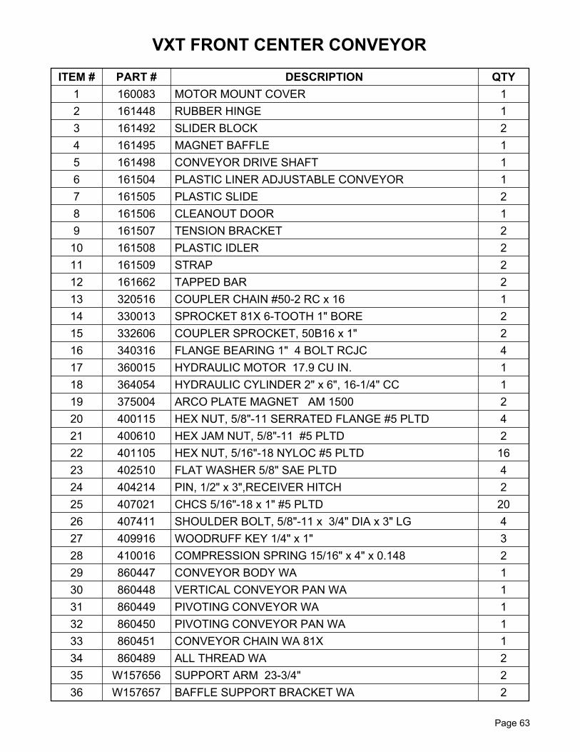
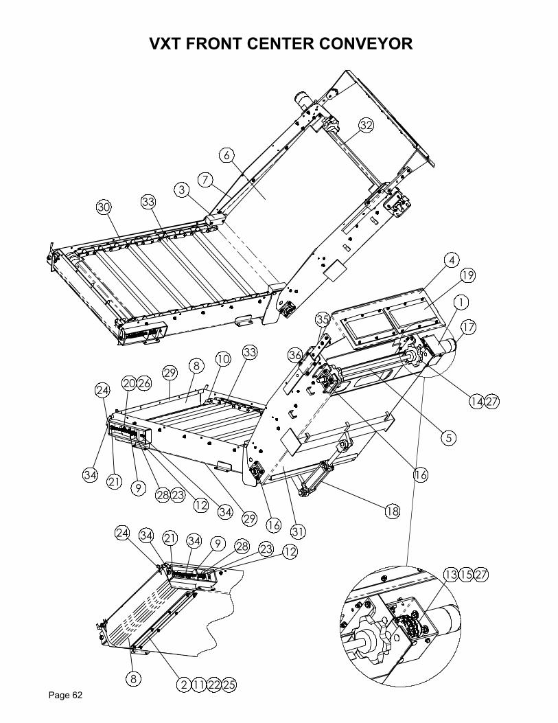
ITEM # PART # DESCRIPTION QTY 1 160083 MOTOR MOUNT COVER 12 161448 RUBBER HINGE 13 161492 SLIDER BLOCK 24 161495 MAGNET BAFFLE 15 161498 CONVEYOR DRIVE SHAFT 16 161504 PLASTIC LINER ADJUSTABLE CONVEYOR 17 161505 PLASTIC SLIDE 28 161506 CLEANOUT DOOR 19 161507 TENSION BRACKET 2
10 161508 PLASTIC IDLER 211 161509 STRAP 212 161662 TAPPED BAR 213 320516 COUPLER CHAIN #50-2 RC x 16 114 330013 SPROCKET 81X 6-TOOTH 1" BORE 215 332606 COUPLER SPROCKET, 50B16 x 1" 216 340316 FLANGE BEARING 1" 4 BOLT RCJC 417 360015 HYDRAULIC MOTOR 17.9 CU IN. 118 364054 HYDRAULIC CYLINDER 2" x 6", 16-1/4" CC 119 375004 ARCO PLATE MAGNET AM 1500 220 400115 HEX NUT, 5/8"-11 SERRATED FLANGE #5 PLTD 421 400610 HEX JAM NUT, 5/8"-11 #5 PLTD 222 401105 HEX NUT, 5/16"-18 NYLOC #5 PLTD 1623 402510 FLAT WASHER 5/8" SAE PLTD 424 404214 PIN, 1/2" x 3",RECEIVER HITCH 225 407021 CHCS 5/16"-18 x 1" #5 PLTD 2026 407411 SHOULDER BOLT, 5/8"-11 x 3/4" DIA x 3" LG 427 409916 WOODRUFF KEY 1/4" x 1" 328 410016 COMPRESSION SPRING 15/16" x 4" x 0.148 229 860447 CONVEYOR BODY WA 130 860448 VERTICAL CONVEYOR PAN WA 131 860449 PIVOTING CONVEYOR WA 132 860450 PIVOTING CONVEYOR PAN WA 133 860451 CONVEYOR CHAIN WA 81X 134 860489 ALL THREAD WA 235 W157656 SUPPORT ARM 23-3/4" 236 W157657 BAFFLE SUPPORT BRACKET WA 2
Page 63
VXT FRONT CENTER CONVEYOR
Page 61
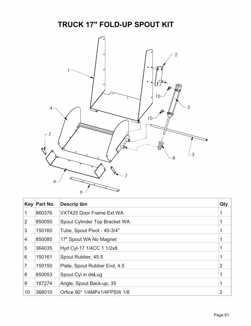
Key Part No. De scrip tion Qty.
1 860376 VXT425 Door Frame Ext WA 1
2 850050 Spout Cyl in der Top Bracket WA 1
3 150160 Tube, Spout Pivot - 40-3/4" 1
4 850085 17" Spout WA No Mag net 1
5 364035 Hyd Cyl-17 1/4CC 1 1/2x8 1
6 150161 Spout Rub ber, 45.5 1
7 150150 Plate, Spout Rub ber End, 4.5 2
8 850053 Spout Cyl in der Lug 1
9 187274 An gle, Spout Back-up, 35 1
10 368010 Orfice 90° 1/4MPx1/4FPSW 1/8 2
TRUCK 17" FOLD-UP SPOUT KIT