VXLAN Technology White Paper - ActForNet · Huawei CloudEngine 8800&7800&6800&5800 Series VXLAN...
235
Huawei CloudEngine 8800&7800&6800&5800 Series VXLAN Technology White Paper Issue 06 Date 2016-07-28 HUAWEI TECHNOLOGIES CO., LTD.
Transcript of VXLAN Technology White Paper - ActForNet · Huawei CloudEngine 8800&7800&6800&5800 Series VXLAN...
Huawei CloudEngine 8800&7800&6800&5800Series
VXLAN Technology White Paper
Issue 06
Date 2016-07-28
HUAWEI TECHNOLOGIES CO., LTD.
Copyright © Huawei Technologies Co., Ltd. 2016. All rights reserved.No part of this document may be reproduced or transmitted in any form or by any means without prior writtenconsent of Huawei Technologies Co., Ltd. Trademarks and Permissions
and other Huawei trademarks are trademarks of Huawei Technologies Co., Ltd.All other trademarks and trade names mentioned in this document are the property of their respectiveholders. NoticeThe purchased products, services and features are stipulated by the contract made between Huawei and thecustomer. All or part of the products, services and features described in this document may not be within thepurchase scope or the usage scope. Unless otherwise specified in the contract, all statements, information,and recommendations in this document are provided "AS IS" without warranties, guarantees orrepresentations of any kind, either express or implied.
The information in this document is subject to change without notice. Every effort has been made in thepreparation of this document to ensure accuracy of the contents, but all statements, information, andrecommendations in this document do not constitute a warranty of any kind, express or implied.
Huawei Technologies Co., Ltd.Address: Huawei Industrial Base
Bantian, LonggangShenzhen 518129People's Republic of China
Website: http://www.huawei.com
Email: [email protected]
Issue 06 (2016-07-28) Huawei Proprietary and ConfidentialCopyright © Huawei Technologies Co., Ltd.
i
Contents
1 VXLAN Overview......................................................................................................................... 1
2 VXLAN Deployment Modes....................................................................................................... 4
3 Principles.........................................................................................................................................93.1 Basic Concepts............................................................................................................................................................. 103.2 Gateway Classification................................................................................................................................................. 153.3 VXLAN Packet Format................................................................................................................................................ 173.4 Tunnel Establishment (Static Mode)............................................................................................................................ 183.5 Tunnel Establishment (MP-BGP Dynamic Mode).......................................................................................................193.6 Tunnel Establishment (BGP EVPN Dynamic Mode)...................................................................................................243.7 Data Packet Forwarding............................................................................................................................................... 303.8 ARP Broadcast Suppression.........................................................................................................................................383.9 All-Active VXLAN Gateway.......................................................................................................................................403.10 VXLAN Dual-Active Access..................................................................................................................................... 453.11 Application for Inter-Domain Active-Active VXLAN Gateways..............................................................................513.12 VXLAN QoS.............................................................................................................................................................. 56
4 Applications..................................................................................................................................584.1 Application for Communication Between Terminal Users on a VXLAN....................................................................594.2 Application for Communication Between Terminal Users on a VXLAN and Legacy Network................................. 604.3 Application in VM Migration Scenarios...................................................................................................................... 62
5 Configuration Notes................................................................................................................... 64
6 Configuring VXLAN (Through the Agile Controller-DCN)...............................................71
7 Configuring VXLAN in Single-Node, Centralized Gateway, and Static Mode..............757.1 Configuring the VXLAN Tunnel Mode and Enabling the VXLAN ACL Extension Function................................... 807.2 Configuring a Service Access Point............................................................................................................................. 817.3 Configuring a VXLAN Tunnel.....................................................................................................................................857.4 Configuring a Layer 3 VXLAN Gateway.................................................................................................................... 877.5 (Optional) Configuring Centralized All-Active Gateways for the VXLAN Network................................................. 887.6 (Optional) Configuring ARP Broadcast Suppression...................................................................................................917.7 (Optional) Disabling a VBDIF Interface from Sending ARP Miss Messages............................................................. 937.8 (Optional) Configuring Static ARP/MAC Address Entries and MAC Address Limiting........................................... 947.9 (Optional) Configuring a VXLAN BD Whitelist for MAC Address Flapping Detection........................................... 96
Huawei CloudEngine 8800&7800&6800&5800 SeriesVXLAN Technology White Paper Contents
Issue 06 (2016-07-28) Huawei Proprietary and ConfidentialCopyright © Huawei Technologies Co., Ltd.
ii
7.10 (Optional) Optimizing Load Balancing on the VXLAN Network............................................................................. 977.11 Checking the Configurations...................................................................................................................................... 98
8 Configuring VXLAN in Single-Node, Centralized Gateway, and BGP EVPN Mode... 998.1 Configuring the VXLAN Tunnel Mode and Enabling the VXLAN ACL Extension Function................................. 1048.2 Configuring a Service Access Point........................................................................................................................... 1058.3 Configuring a VXLAN Tunnel...................................................................................................................................1098.4 Configuring a Layer 3 VXLAN Gateway...................................................................................................................1158.5 (Optional) Configuring Centralized All-Active Gateways for the VXLAN Network............................................... 1168.6 (Optional) Configuring ARP Broadcast Suppression.................................................................................................1198.7 (Optional) Disabling a VBDIF Interface from Sending ARP Miss Messages........................................................... 1208.8 (Optional) Configuring Static ARP/MAC Address Entries and MAC Address Limiting......................................... 1218.9 (Optional) Configuring a VXLAN BD Whitelist for MAC Address Flapping Detection......................................... 1238.10 (Optional) Optimizing Load Balancing on the VXLAN Network........................................................................... 1248.11 Checking the Configurations.................................................................................................................................... 125
9 Configuring VXLAN in Single-Node, Distributed Gateway, and MP-BGP Mode......1279.1 Configuring the VXLAN Tunnel Mode and Enabling the VXLAN ACL Extension Function................................. 1319.2 Configuring a VXLAN Service Access Point............................................................................................................ 1329.3 Configuring a VXLAN Tunnel and a Layer 3 VXLAN Gateway..............................................................................1369.4 (Optional) Configuring ARP Broadcast Suppression.................................................................................................1409.5 (Optional) Disabling a VBDIF Interface from Sending ARP Miss Messages........................................................... 1429.6 (Optional) Configuring Static ARP/MAC Address Entries and MAC Address Limiting......................................... 1439.7 (Optional) Configuring a VXLAN BD Whitelist for MAC Address Flapping Detection......................................... 1459.8 (Optional) Optimizing Load Balancing on the VXLAN Network............................................................................. 1469.9 Checking the Configurations...................................................................................................................................... 147
10 Configuring VXLAN in Single-Node, Distributed Gateway, and BGP EVPN Mode.......................................................................................................................................................... 14810.1 Configuring the VXLAN Tunnel Mode and Enabling the VXLAN ACL Extension Function............................... 15210.2 Configuring a VXLAN Service Access Point.......................................................................................................... 15310.3 Configuring a VXLAN Tunnel and a Layer 3 VXLAN Gateway............................................................................15710.4 (Optional) Configuring ARP Broadcast Suppression...............................................................................................16810.5 (Optional) Disabling a VBDIF Interface from Sending ARP Miss Messages......................................................... 16910.6 (Optional) Configuring Static ARP/MAC Address Entries and MAC Address Limiting....................................... 17010.7 (Optional) Configuring a VXLAN BD Whitelist for MAC Address Flapping Detection....................................... 17210.8 (Optional) Configuring IP Address Conflict Detection Parameters.........................................................................17310.9 (Optional) Optimizing Load Balancing on the VXLAN Network........................................................................... 17410.10 Checking the Configurations.................................................................................................................................. 175
11 Maintaining VXLAN...............................................................................................................17711.1 Configuring the VXLAN Alarm Function................................................................................................................17811.2 Collecting and Checking VXLAN Packet Statistics.................................................................................................17811.3 Clearing VXLAN Packet Statistics...........................................................................................................................17911.4 Checking Statistics about MAC Address Entries in a BD........................................................................................180
Huawei CloudEngine 8800&7800&6800&5800 SeriesVXLAN Technology White Paper Contents
Issue 06 (2016-07-28) Huawei Proprietary and ConfidentialCopyright © Huawei Technologies Co., Ltd.
iii

11.5 Clearing Statistics about Dynamic MAC Address Entries in a BD..........................................................................18011.6 Configuring BGP EVPN Soft Reset......................................................................................................................... 18011.7 Resetting BGP EVPN Connections.......................................................................................................................... 18111.8 Monitoring the VXLAN Operating Status................................................................................................................181
12 Configuration Examples (Single-Node Mode).................................................................. 18312.1 Example for Configuring VXLAN in Centralized Gateway Mode for Static Tunnel Establishment...................... 18412.2 Example for Configuring VXLAN in Centralized Gateway Mode Using BGP EVPN...........................................18912.3 Example for Configuring VXLAN in Distributed Gateway Mode Using MP-BGP................................................19612.4 Example for Configuring VXLAN in Distributed Gateway Mode Using BGP EVPN........................................... 20512.5 Example for Configuring All-Active VXLAN Gateways........................................................................................21312.6 Example for Configuring Dual-Active VXLAN Access..........................................................................................222
13 References................................................................................................................................. 230
Huawei CloudEngine 8800&7800&6800&5800 SeriesVXLAN Technology White Paper Contents
Issue 06 (2016-07-28) Huawei Proprietary and ConfidentialCopyright © Huawei Technologies Co., Ltd.
iv

1 VXLAN Overview
This section describes the definition, purpose, and benefits of the Virtual eXtensible LocalArea Network (VXLAN).
DefinitionVirtual extensible local area network (VXLAN) defined in RFC 7348 is a NetworkVirtualization over Layer 3 (NVO3) technology that uses MAC-in-UDP encapsulation.
PurposeAs a widely deployed core cloud computing technology, server virtualization greatly reducesIT and O&M costs and improves service deployment flexibility.
Huawei CloudEngine 8800&7800&6800&5800 SeriesVXLAN Technology White Paper 1 VXLAN Overview
Issue 06 (2016-07-28) Huawei Proprietary and ConfidentialCopyright © Huawei Technologies Co., Ltd.
1

Figure 1-1 Server virtualization
VSwitchVSwitchVSwitch
VM VM
VM VM
VM VM
VM VM
VM VM
VM VM
VM VM
VM VM
VSwitch
Server1 Server2 Server3 Server4
... ... ... ...
On the network shown in Figure 1-1, a server is virtualized into multiple virtual machines(VMs), each of which functions as a host. A great increase in the number of hosts causes thefollowing problems:l VM scale is limited by the network specification.
On a legacy large Layer 2 network, data packets are forwarded at Layer 2 based on MACentries. However, there is a limit on the MAC table capacity, which subsequently limitsthe number of VMs.
l Network isolation capabilities are limited.Most networks currently use VLANs to implement network isolation. However, thedeployment of VLANs on large-scale virtualized networks has the following limitations:– The VLAN tag field defined in IEEE 802.1Q has only 12 bits and can support only
a maximum of 4094 VLANs, which cannot meet user identification requirements oflarge Layer 2 networks.
– VLANs on legacy Layer 2 networks cannot adapt to dynamic network adjustment.l VM migration scope is limited by the network architecture.
After a VM is started, it may need to be migrated to a new server due to resource issueson the original server, for example, when the CPU usage is too high or memoryresources are inadequate. To ensure uninterrupted services during VM migration, the IPand MAC addresses of the VM must remain unchanged. To carry this out, the service
Huawei CloudEngine 8800&7800&6800&5800 SeriesVXLAN Technology White Paper 1 VXLAN Overview
Issue 06 (2016-07-28) Huawei Proprietary and ConfidentialCopyright © Huawei Technologies Co., Ltd.
2
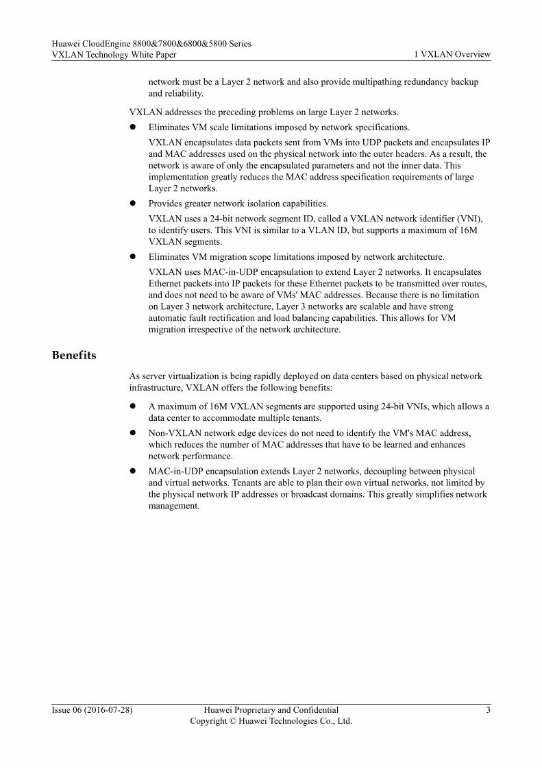
network must be a Layer 2 network and also provide multipathing redundancy backupand reliability.
VXLAN addresses the preceding problems on large Layer 2 networks.l Eliminates VM scale limitations imposed by network specifications.
VXLAN encapsulates data packets sent from VMs into UDP packets and encapsulates IPand MAC addresses used on the physical network into the outer headers. As a result, thenetwork is aware of only the encapsulated parameters and not the inner data. Thisimplementation greatly reduces the MAC address specification requirements of largeLayer 2 networks.
l Provides greater network isolation capabilities.VXLAN uses a 24-bit network segment ID, called a VXLAN network identifier (VNI),to identify users. This VNI is similar to a VLAN ID, but supports a maximum of 16MVXLAN segments.
l Eliminates VM migration scope limitations imposed by network architecture.VXLAN uses MAC-in-UDP encapsulation to extend Layer 2 networks. It encapsulatesEthernet packets into IP packets for these Ethernet packets to be transmitted over routes,and does not need to be aware of VMs' MAC addresses. Because there is no limitationon Layer 3 network architecture, Layer 3 networks are scalable and have strongautomatic fault rectification and load balancing capabilities. This allows for VMmigration irrespective of the network architecture.
BenefitsAs server virtualization is being rapidly deployed on data centers based on physical networkinfrastructure, VXLAN offers the following benefits:
l A maximum of 16M VXLAN segments are supported using 24-bit VNIs, which allows adata center to accommodate multiple tenants.
l Non-VXLAN network edge devices do not need to identify the VM's MAC address,which reduces the number of MAC addresses that have to be learned and enhancesnetwork performance.
l MAC-in-UDP encapsulation extends Layer 2 networks, decoupling between physicaland virtual networks. Tenants are able to plan their own virtual networks, not limited bythe physical network IP addresses or broadcast domains. This greatly simplifies networkmanagement.
Huawei CloudEngine 8800&7800&6800&5800 SeriesVXLAN Technology White Paper 1 VXLAN Overview
Issue 06 (2016-07-28) Huawei Proprietary and ConfidentialCopyright © Huawei Technologies Co., Ltd.
3

2 VXLAN Deployment Modes
Currently, you can deploy a VXLAN network in Single-node mode or Controller mode.
l Single-node mode: In the traditional network deployment node, you need to log in toeach device to configure the devices according to the network plan. Collaboration withcloud platforms cannot be implemented in cloud computing data centers for automaticnetwork deployment.
l Controller mode: To help control and deploy a large Layer 2 network, a controller canbe used. A controller is a unified network control platform that orchestrates and managesnetwork resources and cooperates with the cloud platform to implement automaticservice and network provisioning.
Agile Controller-DCN Model Introduction to Agile Controller-DCN Mode
In Agile Controller-DCN mode, the Agile Controller-DCN dynamically establishesVXLAN tunnels. The Agile Controller-DCN uses NETCONF to establish VXLANtunnels with devices and OpenFlow to control packet forwarding through the tunnels.As shown in Figure 2-1, the Agile Controller-DCN can directly manage the virtualnetwork and obtain virtual network information from the Neutron. The Agile Controller-DCN dynamically calculates network configurations based on virtual networkinformation and automatically maps the information to physical networks.
Huawei CloudEngine 8800&7800&6800&5800 SeriesVXLAN Technology White Paper 2 VXLAN Deployment Modes
Issue 06 (2016-07-28) Huawei Proprietary and ConfidentialCopyright © Huawei Technologies Co., Ltd.
4

Figure 2-1 Networking of the Agile Controller-DCN + VXLAN solution
ACController
L3 Network
Network controller
VXLAN L3 GW
RESTful
Server1 Server2
Cloud platform
Neutron
Server3
VXLAN L3 GW
WEB Portal / APP Portal
NETCONFOpenFlow
NVE
VM1 VM2
vSwitch
VM1 VM2
vSwitch
VM3 VM4
vSwitch
Infrastructure
Server
Table 2-1 describes the layers in the Agile Controller-DCN + VXLAN solution andfunctions of each layer.
Table 2-1 Layers in the Agile Controller-DCN + VXLAN solution
Layer Description
Cloudplatform
Schedules network, computing, and storage resources as required andprovides service management and O&M interface. Neutron is thecomponent of the cloud platform and is used to provide networkservices.
Networkcontroller
Implements network modeling and instantiation.The Agile Controller-DCN uses RESTful interfaces to receive networkmodeling configuration from the cloud platform and convert theconfigurations into related commands, and uses the OpenFlow andNETCONF protocols to establish channels with network devices in theinfrastructure layer and deliver commands to them.
Huawei CloudEngine 8800&7800&6800&5800 SeriesVXLAN Technology White Paper 2 VXLAN Deployment Modes
Issue 06 (2016-07-28) Huawei Proprietary and ConfidentialCopyright © Huawei Technologies Co., Ltd.
5

Layer Description
Infrastructure
Plans physical and virtual networks in a unified manner.l Uses hardware-based VXLAN gateways to improve service
performance.l Is compatible with traditional VLANs.
l Channel Establishment and Maintenance Between the Agile Controller-DCN and
ForwarderThe Agile Controller-DCN can detect the tenant status in real time and obtain the virtualnetwork information from the cloud platform. As shown in Figure 2-2, the AgileController-DCN dynamically calculates network configurations and flow tableinformation based on virtual network information and automatically maps theinformation to physical networks after tenants go online.
Huawei CloudEngine 8800&7800&6800&5800 SeriesVXLAN Technology White Paper 2 VXLAN Deployment Modes
Issue 06 (2016-07-28) Huawei Proprietary and ConfidentialCopyright © Huawei Technologies Co., Ltd.
6

Figure 2-2 Channel establishment and maintenance between the Agile Controller-DCNand device
VM1 MAC1 VM1 IP1 VNI 1 VLAN1 NVE IP1VM2 MAC2 VM2 IP2 VNI 2 VLAN2 NVE IP1VM3 MAC3 VM3 IP3 VNI 1 VLAN1 NVE IP2VM4 MAC4 VM4 IP4 VNI 2 VLAN2 NVE IP2
IP CoreNetwork
VM1
VM2
VSwitchNVE
Server1
VM3
VM4
VSwitchNVE
Server210.1.1.1/24 10.10.1.1/24
Device1
Device2
Device3
VXLAN Tun
nel
NVE
VXLAN Tunnel
ACController
OpenFlow
NETCONF
As shown in Figure 2-2, network administrators must have completed the NETCONFand mandatory VXLAN configuration (for example, creating NVE interfaces andconfiguring VTEP IP addresses) on the device using CLI or Zero Touch Provisioning(ZTP). After the configurations are complete, the Agile Controller-DCN can manage thedevice using NETCONF.– The Agile Controller-DCN automatically allocates a controller node to a network
device based on the load of the controller cluster and establishes an OpenFlowchannel between the network device and the controller node.
– The Agile Controller-DCN receives instructions from the cloud platform andconverts the instructions to configurations of the network device to implementautomatic service provisioning.
– Supporting the ARP protocol stack, the Agile Controller-DCN can learn andprocess ARP packets. The network device and Agile Controller-DCN useOpenFlow to transmit ARP packets.
Huawei CloudEngine 8800&7800&6800&5800 SeriesVXLAN Technology White Paper 2 VXLAN Deployment Modes
Issue 06 (2016-07-28) Huawei Proprietary and ConfidentialCopyright © Huawei Technologies Co., Ltd.
7
– The Agile Controller-DCN delivers the ARP flow table to the network devicethrough the OpenFlow channel to guide packet forwarding. If the OpenFlowchannel between the Agile Controller-DCN and network device is disconnected, theARP flow table will not be aged immediately; therefore, packet forwarding is notinterrupted. After the OpenFlow channel is reconnected, the Agile Controller-DCNsynchronizes the ARP flow table with the network device to ensure consistententries.
Huawei CloudEngine 8800&7800&6800&5800 SeriesVXLAN Technology White Paper 2 VXLAN Deployment Modes
Issue 06 (2016-07-28) Huawei Proprietary and ConfidentialCopyright © Huawei Technologies Co., Ltd.
8
3 Principles
About This Chapter
This section describes VXLAN implementation.
3.1 Basic Concepts
3.2 Gateway Classification
3.3 VXLAN Packet Format
3.4 Tunnel Establishment (Static Mode)
3.5 Tunnel Establishment (MP-BGP Dynamic Mode)
3.6 Tunnel Establishment (BGP EVPN Dynamic Mode)
3.7 Data Packet Forwarding
3.8 ARP Broadcast Suppression
3.9 All-Active VXLAN Gateway
3.10 VXLAN Dual-Active Access
3.11 Application for Inter-Domain Active-Active VXLAN Gateways
3.12 VXLAN QoS
Huawei CloudEngine 8800&7800&6800&5800 SeriesVXLAN Technology White Paper 3 Principles
Issue 06 (2016-07-28) Huawei Proprietary and ConfidentialCopyright © Huawei Technologies Co., Ltd.
9
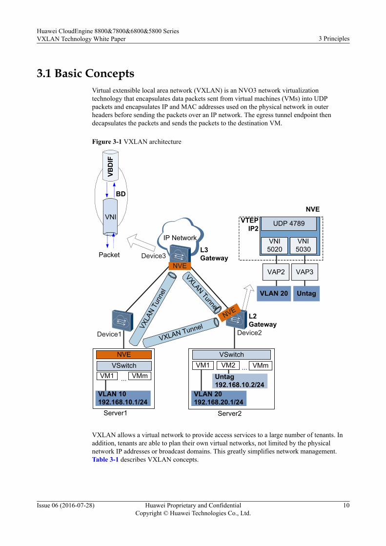
3.1 Basic ConceptsVirtual extensible local area network (VXLAN) is an NVO3 network virtualizationtechnology that encapsulates data packets sent from virtual machines (VMs) into UDPpackets and encapsulates IP and MAC addresses used on the physical network in outerheaders before sending the packets over an IP network. The egress tunnel endpoint thendecapsulates the packets and sends the packets to the destination VM.
Figure 3-1 VXLAN architecture
IP Network
VNI
BD
VBD
IF
L3 GatewayDevice3Packet
NVE
Device1 Device2
L2Gateway
Server1
VLAN 10192.168.10.1/24
VM1 VMm...
VSwitchNVE
Server2
VLAN 20192.168.20.1/24
VM1 ...
VSwitchVM2
Untag192.168.10.2/24
VMm
NVE
VLAN 20
UDP 4789
VNI 5020
VTEPIP2
VNI 5030
Untag
VAP2 VAP3
VXLA
N Tu
nnel
VXLAN Tunnel
VXLAN TunnelNVE
VXLAN allows a virtual network to provide access services to a large number of tenants. Inaddition, tenants are able to plan their own virtual networks, not limited by the physicalnetwork IP addresses or broadcast domains. This greatly simplifies network management.Table 3-1 describes VXLAN concepts.
Huawei CloudEngine 8800&7800&6800&5800 SeriesVXLAN Technology White Paper 3 Principles
Issue 06 (2016-07-28) Huawei Proprietary and ConfidentialCopyright © Huawei Technologies Co., Ltd.
10
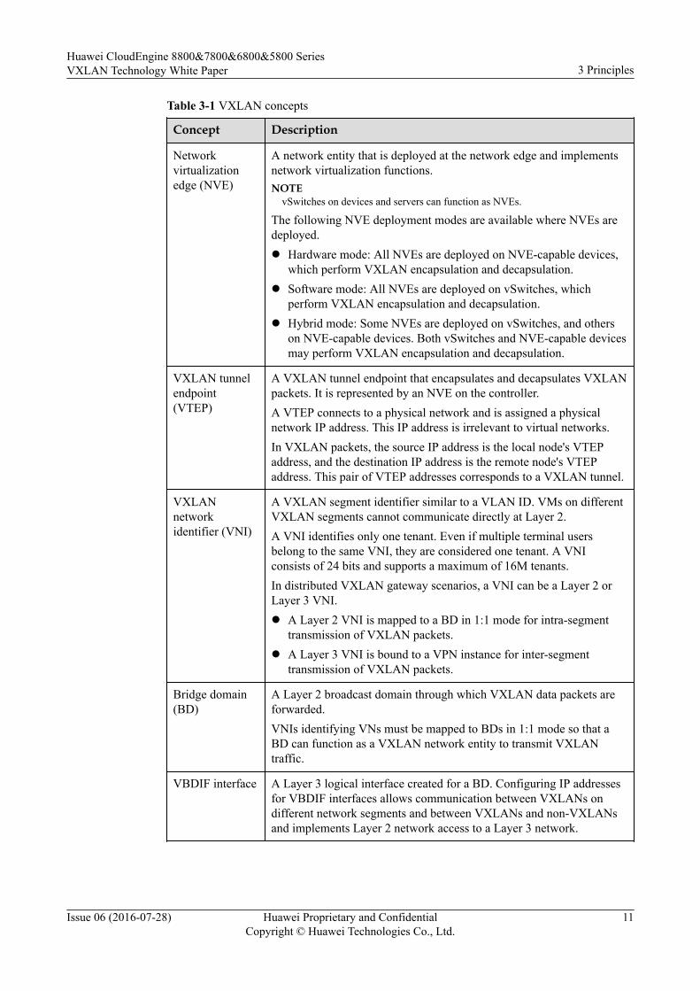
Table 3-1 VXLAN concepts
Concept Description
Networkvirtualizationedge (NVE)
A network entity that is deployed at the network edge and implementsnetwork virtualization functions.NOTE
vSwitches on devices and servers can function as NVEs.
The following NVE deployment modes are available where NVEs aredeployed.l Hardware mode: All NVEs are deployed on NVE-capable devices,
which perform VXLAN encapsulation and decapsulation.l Software mode: All NVEs are deployed on vSwitches, which
perform VXLAN encapsulation and decapsulation.l Hybrid mode: Some NVEs are deployed on vSwitches, and others
on NVE-capable devices. Both vSwitches and NVE-capable devicesmay perform VXLAN encapsulation and decapsulation.
VXLAN tunnelendpoint(VTEP)
A VXLAN tunnel endpoint that encapsulates and decapsulates VXLANpackets. It is represented by an NVE on the controller.A VTEP connects to a physical network and is assigned a physicalnetwork IP address. This IP address is irrelevant to virtual networks.In VXLAN packets, the source IP address is the local node's VTEPaddress, and the destination IP address is the remote node's VTEPaddress. This pair of VTEP addresses corresponds to a VXLAN tunnel.
VXLANnetworkidentifier (VNI)
A VXLAN segment identifier similar to a VLAN ID. VMs on differentVXLAN segments cannot communicate directly at Layer 2.A VNI identifies only one tenant. Even if multiple terminal usersbelong to the same VNI, they are considered one tenant. A VNIconsists of 24 bits and supports a maximum of 16M tenants.In distributed VXLAN gateway scenarios, a VNI can be a Layer 2 orLayer 3 VNI.l A Layer 2 VNI is mapped to a BD in 1:1 mode for intra-segment
transmission of VXLAN packets.l A Layer 3 VNI is bound to a VPN instance for inter-segment
transmission of VXLAN packets.
Bridge domain(BD)
A Layer 2 broadcast domain through which VXLAN data packets areforwarded.VNIs identifying VNs must be mapped to BDs in 1:1 mode so that aBD can function as a VXLAN network entity to transmit VXLANtraffic.
VBDIF interface A Layer 3 logical interface created for a BD. Configuring IP addressesfor VBDIF interfaces allows communication between VXLANs ondifferent network segments and between VXLANs and non-VXLANsand implements Layer 2 network access to a Layer 3 network.
Huawei CloudEngine 8800&7800&6800&5800 SeriesVXLAN Technology White Paper 3 Principles
Issue 06 (2016-07-28) Huawei Proprietary and ConfidentialCopyright © Huawei Technologies Co., Ltd.
11
Concept Description
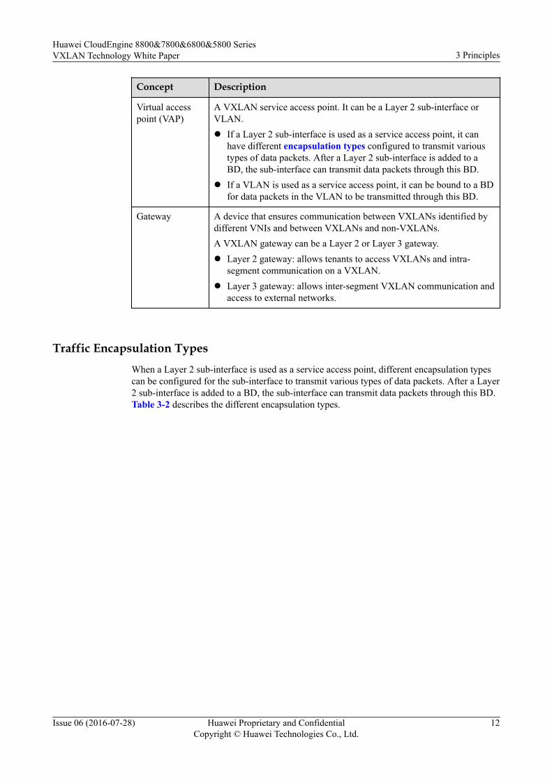
Virtual accesspoint (VAP)
A VXLAN service access point. It can be a Layer 2 sub-interface orVLAN.l If a Layer 2 sub-interface is used as a service access point, it can
have different encapsulation types configured to transmit varioustypes of data packets. After a Layer 2 sub-interface is added to aBD, the sub-interface can transmit data packets through this BD.
l If a VLAN is used as a service access point, it can be bound to a BDfor data packets in the VLAN to be transmitted through this BD.
Gateway A device that ensures communication between VXLANs identified bydifferent VNIs and between VXLANs and non-VXLANs.A VXLAN gateway can be a Layer 2 or Layer 3 gateway.l Layer 2 gateway: allows tenants to access VXLANs and intra-
segment communication on a VXLAN.l Layer 3 gateway: allows inter-segment VXLAN communication and
access to external networks.
Traffic Encapsulation TypesWhen a Layer 2 sub-interface is used as a service access point, different encapsulation typescan be configured for the sub-interface to transmit various types of data packets. After a Layer2 sub-interface is added to a BD, the sub-interface can transmit data packets through this BD.Table 3-2 describes the different encapsulation types.
Huawei CloudEngine 8800&7800&6800&5800 SeriesVXLAN Technology White Paper 3 Principles
Issue 06 (2016-07-28) Huawei Proprietary and ConfidentialCopyright © Huawei Technologies Co., Ltd.
12
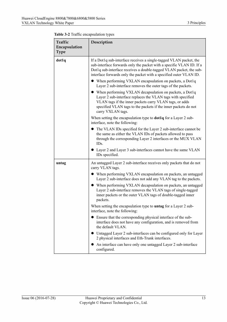
Table 3-2 Traffic encapsulation types
TrafficEncapsulationType
Description
dot1q If a Dot1q sub-interface receives a single-tagged VLAN packet, thesub-interface forwards only the packet with a specifie VLAN ID. If aDot1q sub-interface receives a double-tagged VLAN packet, the sub-interface forwards only the packet with a specified outer VLAN ID.l When performing VXLAN encapsulation on packets, a Dot1q
Layer 2 sub-interface removes the outer tags of the packets.l When performing VXLAN decapsulation on packets, a Dot1q
Layer 2 sub-interface replaces the VLAN tags with specifiedVLAN tags if the inner packets carry VLAN tags, or addsspecified VLAN tags to the packets if the inner packets do notcarry VXLAN tags.
When setting the encapsulation type to dot1q for a Layer 2 sub-interface, note the following:l The VLAN IDs specified for the Layer 2 sub-interface cannot be
the same as either the VLAN IDs of packets allowed to passthrough the corresponding Layer 2 interfaces or the MUX VLANIDs.
l Layer 2 and Layer 3 sub-interfaces cannot have the same VLANIDs specified.
untag An untagged Layer 2 sub-interface receives only packets that do notcarry VLAN tags.l When performing VXLAN encapsulation on packets, an untagged
Layer 2 sub-interface does not add any VLAN tag to the packets.l When performing VXLAN decapsulation on packets, an untagged
Layer 2 sub-interface removes the VLAN tags of single-taggedinner packets or the outer VLAN tags of double-tagged innerpackets.
When setting the encapsulation type to untag for a Layer 2 sub-interface, note the following:l Ensure that the corresponding physical interface of the sub-
interface does not have any configuration, and is removed fromthe default VLAN.
l Untagged Layer 2 sub-interfaces can be configured only for Layer2 physical interfaces and Eth-Trunk interfaces.
l An interface can have only one untagged Layer 2 sub-interfaceconfigured.
Huawei CloudEngine 8800&7800&6800&5800 SeriesVXLAN Technology White Paper 3 Principles
Issue 06 (2016-07-28) Huawei Proprietary and ConfidentialCopyright © Huawei Technologies Co., Ltd.
13
TrafficEncapsulationType
Description
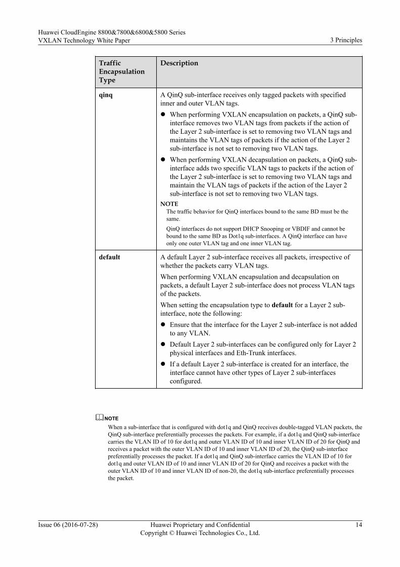
qinq A QinQ sub-interface receives only tagged packets with specifiedinner and outer VLAN tags.l When performing VXLAN encapsulation on packets, a QinQ sub-
interface removes two VLAN tags from packets if the action ofthe Layer 2 sub-interface is set to removing two VLAN tags andmaintains the VLAN tags of packets if the action of the Layer 2sub-interface is not set to removing two VLAN tags.
l When performing VXLAN decapsulation on packets, a QinQ sub-interface adds two specific VLAN tags to packets if the action ofthe Layer 2 sub-interface is set to removing two VLAN tags andmaintain the VLAN tags of packets if the action of the Layer 2sub-interface is not set to removing two VLAN tags.
NOTEThe traffic behavior for QinQ interfaces bound to the same BD must be thesame.
QinQ interfaces do not support DHCP Snooping or VBDIF and cannot bebound to the same BD as Dot1q sub-interfaces. A QinQ interface can haveonly one outer VLAN tag and one inner VLAN tag.
default A default Layer 2 sub-interface receives all packets, irrespective ofwhether the packets carry VLAN tags.When performing VXLAN encapsulation and decapsulation onpackets, a default Layer 2 sub-interface does not process VLAN tagsof the packets.When setting the encapsulation type to default for a Layer 2 sub-interface, note the following:l Ensure that the interface for the Layer 2 sub-interface is not added
to any VLAN.l Default Layer 2 sub-interfaces can be configured only for Layer 2
physical interfaces and Eth-Trunk interfaces.l If a default Layer 2 sub-interface is created for an interface, the
interface cannot have other types of Layer 2 sub-interfacesconfigured.
NOTEWhen a sub-interface that is configured with dot1q and QinQ receives double-tagged VLAN packets, theQinQ sub-interface preferentially processes the packets. For example, if a dot1q and QinQ sub-interfacecarries the VLAN ID of 10 for dot1q and outer VLAN ID of 10 and inner VLAN ID of 20 for QinQ andreceives a packet with the outer VLAN ID of 10 and inner VLAN ID of 20, the QinQ sub-interfacepreferentially processes the packet. If a dot1q and QinQ sub-interface carries the VLAN ID of 10 fordot1q and outer VLAN ID of 10 and inner VLAN ID of 20 for QinQ and receives a packet with theouter VLAN ID of 10 and inner VLAN ID of non-20, the dot1q sub-interface preferentially processesthe packet.
Huawei CloudEngine 8800&7800&6800&5800 SeriesVXLAN Technology White Paper 3 Principles
Issue 06 (2016-07-28) Huawei Proprietary and ConfidentialCopyright © Huawei Technologies Co., Ltd.
14

3.2 Gateway ClassificationA device that ensures communication between VXLANs identified by different VNIs andbetween VXLANs and non-VXLANs.
A VXLAN gateway can be a Layer 2 or Layer 3 gateway.l Layer 2 gateway: allows tenants to access VXLANs and intra-segment communication
on a VXLAN.l Layer 3 gateway: allows inter-segment VXLAN communication and access to external
networks.
VXLAN Layer 3 gateways can be deployed in centralized or distributed mode.
Centralized VXLAN Gateway Mode
In this mode, Layer 3 gateways are configured on one device. On the network shown inFigure 3-2, traffic across network segments is forwarded through Layer 3 gateways toimplement centralized traffic management.
Figure 3-2 Centralized VXLAN gateway networking
Inter-segment traffic
Leaf1 Leaf2
Spine1 Spine2L3 Gateway
L2 Gateway
Server110.1.1.1/24
Server210.10.1.1/24
Server310.20.1.1/24
Centralized VXLAN gateway deployment has its advantages and disadvantages.l Advantage: Inter-segment traffic can be centrally managed, and gateway deployment and
management is easy.l Disadvantages:
– Forwarding paths are not optimal. Inter-segment Layer 3 traffic of data centersconnected to the same Layer 2 gateway must be transmitted to the centralized Layer3 gateway for forwarding.
Huawei CloudEngine 8800&7800&6800&5800 SeriesVXLAN Technology White Paper 3 Principles
Issue 06 (2016-07-28) Huawei Proprietary and ConfidentialCopyright © Huawei Technologies Co., Ltd.
15
– The ARP entry specification is a bottleneck. ARP entries must be generated fortenants on the Layer 3 gateway. However, only a limited number of ARP entries areallowed by the Layer 3 gateway, impeding data center network expansion.
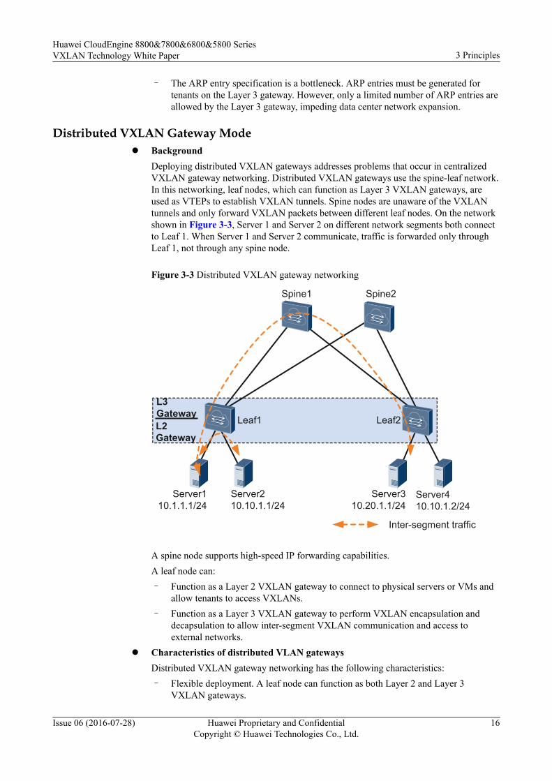
Distributed VXLAN Gateway Model Background
Deploying distributed VXLAN gateways addresses problems that occur in centralizedVXLAN gateway networking. Distributed VXLAN gateways use the spine-leaf network.In this networking, leaf nodes, which can function as Layer 3 VXLAN gateways, areused as VTEPs to establish VXLAN tunnels. Spine nodes are unaware of the VXLANtunnels and only forward VXLAN packets between different leaf nodes. On the networkshown in Figure 3-3, Server 1 and Server 2 on different network segments both connectto Leaf 1. When Server 1 and Server 2 communicate, traffic is forwarded only throughLeaf 1, not through any spine node.
Figure 3-3 Distributed VXLAN gateway networking
Inter-segment traffic
Leaf1 Leaf2
Spine1 Spine2
L3 GatewayL2 Gateway
Server110.1.1.1/24
Server210.10.1.1/24
Server310.20.1.1/24
Server410.10.1.2/24
A spine node supports high-speed IP forwarding capabilities.A leaf node can:– Function as a Layer 2 VXLAN gateway to connect to physical servers or VMs and
allow tenants to access VXLANs.– Function as a Layer 3 VXLAN gateway to perform VXLAN encapsulation and
decapsulation to allow inter-segment VXLAN communication and access toexternal networks.
l Characteristics of distributed VLAN gatewaysDistributed VXLAN gateway networking has the following characteristics:– Flexible deployment. A leaf node can function as both Layer 2 and Layer 3
VXLAN gateways.
Huawei CloudEngine 8800&7800&6800&5800 SeriesVXLAN Technology White Paper 3 Principles
Issue 06 (2016-07-28) Huawei Proprietary and ConfidentialCopyright © Huawei Technologies Co., Ltd.
16

– Improved network expansion capabilities. A leaf node only needs to learn the ARPentries of servers attached to it. A centralized Layer 3 gateway in the same scenario,however, has to learn the ARP entries of all servers on the network. Therefore, theARP entry specification is no longer a bottleneck on a distributed VXLAN gateway.
3.3 VXLAN Packet FormatVXLAN is a network virtualization technique that uses MAC-in-UDP encapsulation byadding a UDP header and a VXLAN header before an original Ethernet packet. Figure 3-4shows the VXLAN packet format.
Figure 3-4 VXLAN packet format
OuterEthernetheader
OuterIP
header
OuterUDP
header
VXLANheader
InnerIP
header
InnerEthernetheader
Payload
MAC DA
802.1QTag
48 bits 48 bits 32 bitsMAC SA
EthernetType
16 bits
…... IP SA
72 bits 8 bits 16 bits 32 bits
Protocol IP DA
32 bits
…...
SourcePort
DestPort(VXLAN Port)
UDPLength
UDPChecksum
16 bits 16 bits 16 bits 16 bits
VXLAN Flags (00001000) Reserved VNI Reserved
8 bits 24 bits 24 bits 8 bits
Original packetVXLAN encapsulation
Table 3-3 Fields in the VXLAN packet format
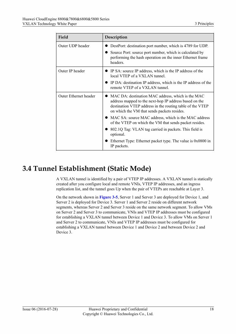
Field Description
VXLAN header l VXLAN Flags (8 bits): The value is 00001000.l VNI (24 bits): VXLAN Segment ID or VXLAN Network
Identifier used to identify a VXLAN segment.l Reserved fields (24 bits and 8 bits): must be set to 0.
Huawei CloudEngine 8800&7800&6800&5800 SeriesVXLAN Technology White Paper 3 Principles
Issue 06 (2016-07-28) Huawei Proprietary and ConfidentialCopyright © Huawei Technologies Co., Ltd.
17
Field Description
Outer UDP header l DestPort: destination port number, which is 4789 for UDP.l Source Port: source port number, which is calculated by
performing the hash operation on the inner Ethernet frameheaders.
Outer IP header l IP SA: source IP address, which is the IP address of thelocal VTEP of a VXLAN tunnel.
l IP DA: destination IP address, which is the IP address of theremote VTEP of a VXLAN tunnel.
Outer Ethernet header l MAC DA: destination MAC address, which is the MACaddress mapped to the next-hop IP address based on thedestination VTEP address in the routing table of the VTEPon which the VM that sends packets resides.
l MAC SA: source MAC address, which is the MAC addressof the VTEP on which the VM that sends packet resides.
l 802.1Q Tag: VLAN tag carried in packets. This field isoptional.
l Ethernet Type: Ethernet packet type. The value is 0x0800 inIP packets.
3.4 Tunnel Establishment (Static Mode)A VXLAN tunnel is identified by a pair of VTEP IP addresses. A VXLAN tunnel is staticallycreated after you configure local and remote VNIs, VTEP IP addresses, and an ingressreplication list, and the tunnel goes Up when the pair of VTEPs are reachable at Layer 3.
On the network shown in Figure 3-5, Server 1 and Server 3 are deployed for Device 1, andServer 2 is deployed for Device 3. Server 1 and Server 2 reside on different networksegments, whereas Server 2 and Server 3 reside on the same network segment. To allow VMson Server 2 and Server 3 to communicate, VNIs and VTEP IP addresses must be configuredfor establishing a VXLAN tunnel between Device 1 and Device 3. To allow VMs on Server 1and Server 2 to communicate, VNIs and VTEP IP addresses must be configured forestablishing a VXLAN tunnel between Device 1 and Device 2 and between Device 2 andDevice 3.
Huawei CloudEngine 8800&7800&6800&5800 SeriesVXLAN Technology White Paper 3 Principles
Issue 06 (2016-07-28) Huawei Proprietary and ConfidentialCopyright © Huawei Technologies Co., Ltd.
18

Figure 3-5 VXLAN networking
Server1192.168.10.1/24
Server2192.168.20.1/24
VM1 VMm
VSwitch VSwitch
VM1 VMn
inte
rface
2
interface2
NVE
VNI: 10VNI: 20
VTEP: 3.3.3.3/32
... ...
VLAN 10 VLAN 20
Device2
Device1VNI: 10VNI: 20VTEP
2.2.2.2/32
VNI: 20VTEP
4.4.4.4/32
Device3
Server3192.168.20.2/24
VM1 VMm
VSwitch
...
VLAN 30
interface3
VXLAN Tunnel
VXLAN Tun
nel VXLAN Tunnel
3.5 Tunnel Establishment (MP-BGP Dynamic Mode)Multi-protocol Extensions for Border Gateway Protocol (MP-BGP) is applicable to thedistributed gateway scenario to implement dynamic establishment and management ofVXLAN tunnels and learning of host routes.
In a distributed VXLAN gateway scenario where MP-BGP runs on each leaf node, inter-segment communication requires leaf nodes to learn user-side ARP entries, generate hostroutes from these entries, and advertise these routes to other BGP peers. BGP peers thendynamically establish VXLAN tunnels based on their local VTEP IP addresses and the VTEPIP addresses carried in the remote-nexthop attributes of received BGP protocol packets. TheMP-BGP control plane implementation process is as follows:
1. VXLAN tunnel managementOn the network shown in Figure 3-6, a leaf node assigns a Layer 2 VNI to each segmentand a Layer 3 VNI to each tenant identified by a VPN instance. When Leaf 1 forwardstraffic at Layer 3, Leaf 1 transmits tenants' VNI IDs to Leaf 2 through the VXLANtunnel. Leaf 2 identifies VPNs based on tenants' VNI IDs to determine whether tenantsbelong to the same VPN.
Huawei CloudEngine 8800&7800&6800&5800 SeriesVXLAN Technology White Paper 3 Principles
Issue 06 (2016-07-28) Huawei Proprietary and ConfidentialCopyright © Huawei Technologies Co., Ltd.
19

This example illustrates VXLAN tunnel management for distributed VXLAN gatewaysusing Server 1 accessing other servers on a different segment.
a. MP-BGP dynamically manages the VXLAN tunnel between Leaf 1 and Leaf 2.After Leaf 1 learns Server 1's host routes generated based on ARP entries, Leaf 1uses BGP to advertise Server 1's host routes to Leaf 2 through the remote-nexthopattribute.
b. Upon receipt of Server 1's host routes, Leaf 2 checks whether the next hopaddresses of these routes are the same as Leaf 2's VTEP IP address. If they are thesame, Leaf 2 dynamically establishes a VXLAN tunnel based on Leaf 1's VTEP IPaddress and Leaf 2's VTEP IP address.
c. After Leaf 1 receives packets from Server 1 to Server 3, Leaf 1 searches the hostrouting table and finds the VXLAN tunnel for Server 3. Leaf 1 then encapsulatesthe packets from Server 1 into VXLAN packets and sends the VXLAN packets toLeaf 2 connected to Server 3. Leaf 2 then decapsulates the VXLAN packets andforwards the packets to Server 3.
A VXLAN tunnel between two distributed gateways is identified by a pair of VTEP IPaddresses. If multiple host routes carry the same source VTEP IP address and the samenext-hop VTEP IP address, only one VXLAN tunnel can be established.
When Leaf 1 no longer has any host attached, Leaf 1 will withdraw all host routes andnotify its BGP peers of the withdrawal. When Leaf 2 finds no reachable host routes onLeaf 1, Leaf 2 will dynamically delete the VXLAN tunnel established with Leaf 1.
Figure 3-6 VXLAN tunnel management
Inter-segment traffic
Leaf1 Leaf2
Spine1 Spine2
L3 GatewayL2 Gateway
Server110.1.1.1/24
Server210.10.1.1/24
Server310.20.1.1/24
Server410.10.1.2/24
2. ARP learning
The following uses the network shown in Figure 3-7 as an example to describe howLeaf 1 learns Server 1's ARP entry.
a. Server 1 sends an ARP request.
Huawei CloudEngine 8800&7800&6800&5800 SeriesVXLAN Technology White Paper 3 Principles
Issue 06 (2016-07-28) Huawei Proprietary and ConfidentialCopyright © Huawei Technologies Co., Ltd.
20
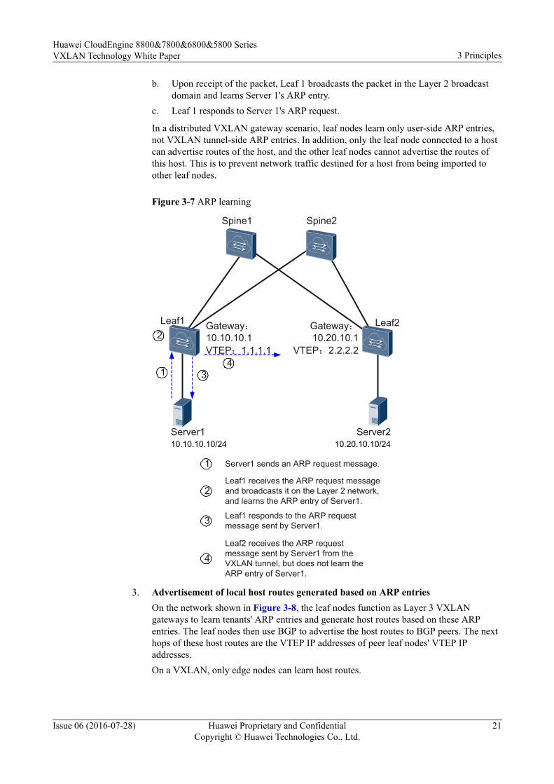
b. Upon receipt of the packet, Leaf 1 broadcasts the packet in the Layer 2 broadcastdomain and learns Server 1's ARP entry.
c. Leaf 1 responds to Server 1's ARP request.
In a distributed VXLAN gateway scenario, leaf nodes learn only user-side ARP entries,not VXLAN tunnel-side ARP entries. In addition, only the leaf node connected to a hostcan advertise routes of the host, and the other leaf nodes cannot advertise the routes ofthis host. This is to prevent network traffic destined for a host from being imported toother leaf nodes.
Figure 3-7 ARP learning
Leaf1 Leaf2
Spine1 Spine2
Server110.10.10.10/24
Server210.20.10.10/24
Gateway:10.10.10.1VTEP:1.1.1.1
Gateway:10.20.10.1
VTEP:2.2.2.2
1
2
34
1 Server1 sends an ARP request message.
Leaf1 receives the ARP request message and broadcasts it on the Layer 2 network, and learns the ARP entry of Server1.
2
3 Leaf1 responds to the ARP request message sent by Server1.
Leaf2 receives the ARP request message sent by Server1 from the VXLAN tunnel, but does not learn the ARP entry of Server1.
4
3. Advertisement of local host routes generated based on ARP entriesOn the network shown in Figure 3-8, the leaf nodes function as Layer 3 VXLANgateways to learn tenants' ARP entries and generate host routes based on these ARPentries. The leaf nodes then use BGP to advertise the host routes to BGP peers. The nexthops of these host routes are the VTEP IP addresses of peer leaf nodes' VTEP IPaddresses.On a VXLAN, only edge nodes can learn host routes.
Huawei CloudEngine 8800&7800&6800&5800 SeriesVXLAN Technology White Paper 3 Principles
Issue 06 (2016-07-28) Huawei Proprietary and ConfidentialCopyright © Huawei Technologies Co., Ltd.
21
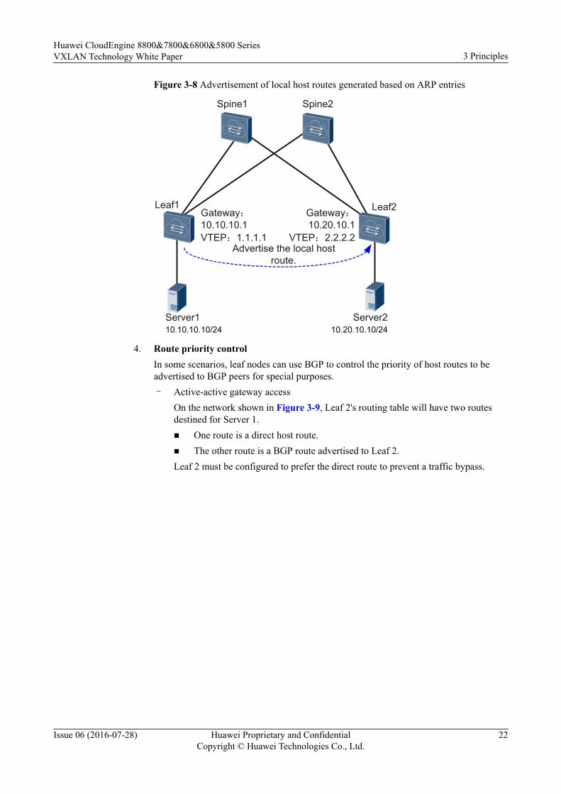
Figure 3-8 Advertisement of local host routes generated based on ARP entries
Leaf1 Leaf2
Spine1 Spine2
Server110.10.10.10/24
Server210.20.10.10/24
Gateway:10.10.10.1VTEP:1.1.1.1
Gateway:10.20.10.1
VTEP:2.2.2.2Advertise the local host
route.
4. Route priority controlIn some scenarios, leaf nodes can use BGP to control the priority of host routes to beadvertised to BGP peers for special purposes.– Active-active gateway access
On the network shown in Figure 3-9, Leaf 2's routing table will have two routesdestined for Server 1.n One route is a direct host route.n The other route is a BGP route advertised to Leaf 2.Leaf 2 must be configured to prefer the direct route to prevent a traffic bypass.
Huawei CloudEngine 8800&7800&6800&5800 SeriesVXLAN Technology White Paper 3 Principles
Issue 06 (2016-07-28) Huawei Proprietary and ConfidentialCopyright © Huawei Technologies Co., Ltd.
22
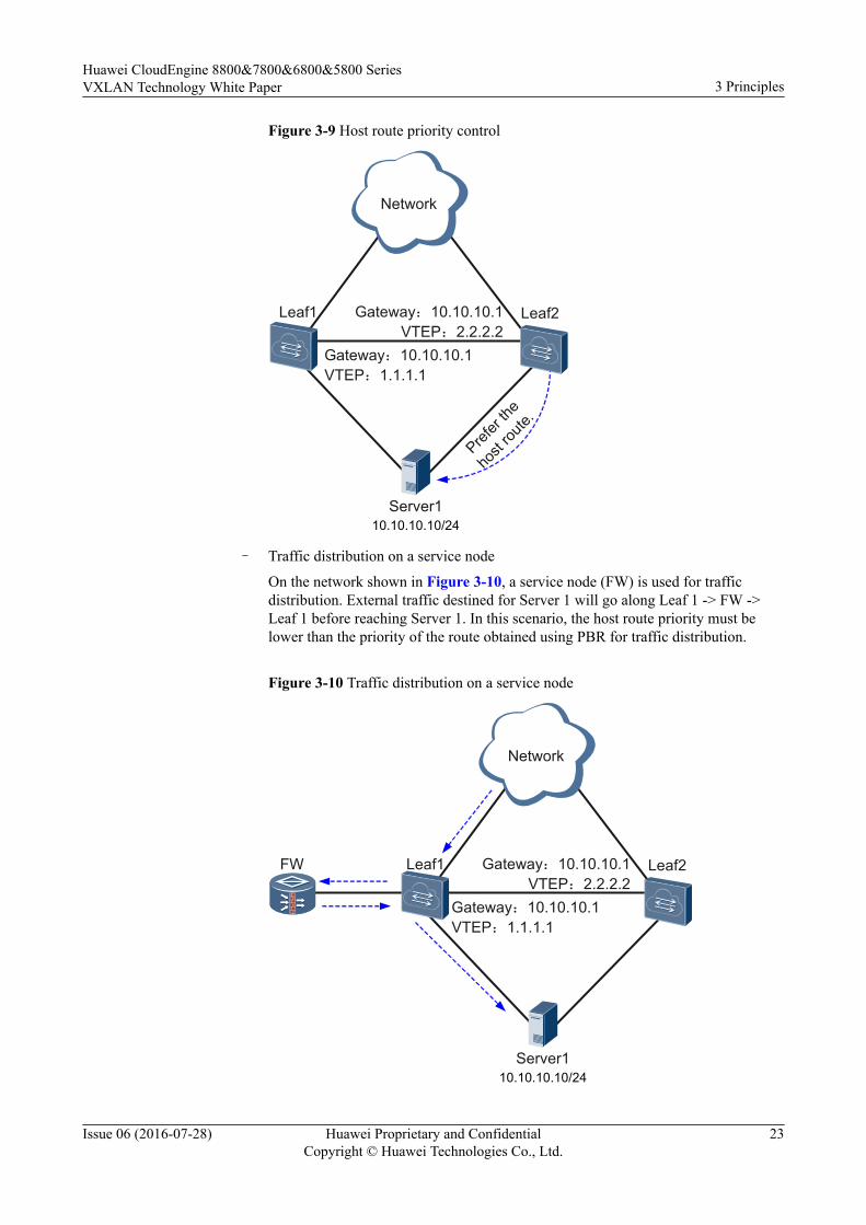
Figure 3-9 Host route priority control
Server110.10.10.10/24
Gateway:10.10.10.1VTEP:1.1.1.1
Gateway:10.10.10.1VTEP:2.2.2.2
Network
Leaf1 Leaf2
Prefer
the
host
route.
– Traffic distribution on a service node
On the network shown in Figure 3-10, a service node (FW) is used for trafficdistribution. External traffic destined for Server 1 will go along Leaf 1 -> FW ->Leaf 1 before reaching Server 1. In this scenario, the host route priority must belower than the priority of the route obtained using PBR for traffic distribution.
Figure 3-10 Traffic distribution on a service node
Server110.10.10.10/24
Gateway:10.10.10.1VTEP:1.1.1.1
Gateway:10.10.10.1VTEP:2.2.2.2
Network
Leaf1 Leaf2FW
Huawei CloudEngine 8800&7800&6800&5800 SeriesVXLAN Technology White Paper 3 Principles
Issue 06 (2016-07-28) Huawei Proprietary and ConfidentialCopyright © Huawei Technologies Co., Ltd.
23
3.6 Tunnel Establishment (BGP EVPN Dynamic Mode)Ethernet Virtual Private Network Border Gateway Protocol (BGP EVPN) is applicable to thedistributed or centralized gateway scenario to implement dynamic establishment andmanagement of VXLAN tunnels and learning of host routes.
BGP EVPN for Centralized VXLAN GatewaysBGP EVPN extends BGP by defining a new type of network layer reachability information(NLRI) called EVPN NLRI. In a centralized VXLAN gateway scenario, EVPN can functionas the VXLAN control plane by using inclusive multicast routes carried in the EVPN NLRI toexchange information between VXLAN gateways for tunnel establishment. A local gatewaymust obtain the VTEP IP address and VNI of a remote gateway before establishing a VXLANtunnel with the remote gateway. On the network shown in Figure 3-11, Device 1 and Device2 use EVPN inclusive multicast routes to exchange information for VXLAN tunnelestablishment. The process is as follows:
1. Create EVPN instances on Device 1 and Device 2 and establish an BGP EVPN peerrelationship between Device 1 and Device 2.
2. Device 1 and Device 2 use BGP EVPN to send EVPN routes comprised of inclusivemulticast route prefixes and PMSI attributes. VTEP IP addresses are stored in theOriginating Router's IP Address field in the inclusive multicast route prefix, and Layer 2VNIs are stored in PMSI attributes.
3. Upon receipt of the EVPN routes, a gateway matches the export VPN target carried inthe route against the import VPN target of its local EVPN instance. If the two VPNtargets match, the gateway accepts the route and stores the VTEP IP address and VNIcarried in the route for later packet transmission over the VXLAN tunnel. If the twoVPN targets do not match, the gateway drops the route.
NOTE
In this example, the import VPN target of one EVPN instance must match the export VPN target of theother EVPN instance. Otherwise, the VXLAN tunnel cannot be established. If only one end cansuccessfully accept the IRB or IP prefix route, this end can establish a VXLAN tunnel to the other end,but cannot exchange data packets with the other end. The other end drops packets after confirming thatthere is no VXLAN tunnel to the end that has sent these packets.
Huawei CloudEngine 8800&7800&6800&5800 SeriesVXLAN Technology White Paper 3 Principles
Issue 06 (2016-07-28) Huawei Proprietary and ConfidentialCopyright © Huawei Technologies Co., Ltd.
24
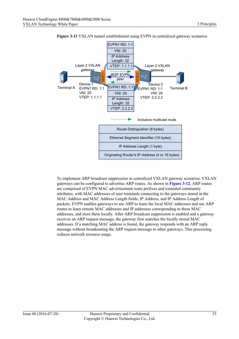
Figure 3-11 VXLAN tunnel establishment using EVPN in centralized gateway scenarios
Terminal B
Inclusive multicast route
Terminal ADevice 1EVPN1 RD: 1:1VNI: 20VTEP: 1.1.1.1
Device 2EVPN1 RD: 1:1
VNI: 20VTEP: 2.2.2.2
EVPN1 RD: 1:1
VNI: 20IP Address Length: 32
VTEP: 2.2.2.2
VNI: 20IP Address Length: 32
VTEP: 1.1.1.1
Route Distinguisher (8 bytes)
Ethernet Segment Identifier (10 bytes)
IP Address Length (1 byte)
Originating Router's IP Address (4 or 16 bytes)
BGP EVPN peer
Layer 2 VXLANgateway
Layer 2 VXLANgateway
EVPN1 RD: 1:1
NV
E1
NVE
2
To implement ARP broadcast suppression in centralized VXLAN gateway scenarios, VXLANgateways can be configured to advertise ARP routes. As shown in Figure 3-12, ARP routesare comprised of EVPN MAC advertisement route prefixes and extended communityattributes, with MAC addresses of user terminals connecting to the gateways stored in theMAC Address and MAC Address Length fields, IP Address, and IP Address Length ofpackets. EVPN enables gateways to use ARP to learn the local MAC addresses and use ARProutes to learn remote MAC addresses and IP addresses corresponding to these MACaddresses, and store them locally. After ARP broadcast suppression is enabled and a gatewayreceives an ARP request message, the gateway first searches the locally stored MACaddresses. If a matching MAC address is found, the gateway responds with an ARP replymessage without broadcasting the ARP request message to other gateways. This processingreduces network resource usage.
Huawei CloudEngine 8800&7800&6800&5800 SeriesVXLAN Technology White Paper 3 Principles
Issue 06 (2016-07-28) Huawei Proprietary and ConfidentialCopyright © Huawei Technologies Co., Ltd.
25
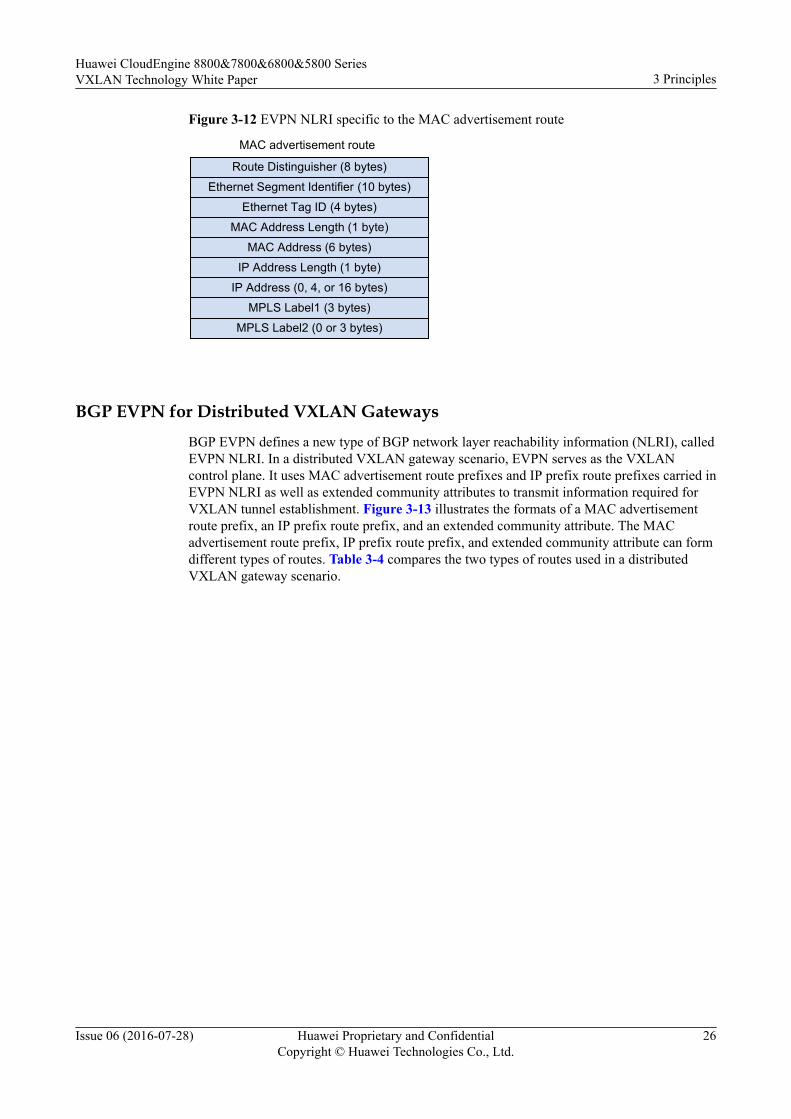
Figure 3-12 EVPN NLRI specific to the MAC advertisement route
Route Distinguisher (8 bytes)
Ethernet Segment Identifier (10 bytes)
Ethernet Tag ID (4 bytes)
MAC Address Length (1 byte)
MAC Address (6 bytes)
IP Address Length (1 byte)
IP Address (0, 4, or 16 bytes)
MPLS Label1 (3 bytes)
MPLS Label2 (0 or 3 bytes)
MAC advertisement route
BGP EVPN for Distributed VXLAN GatewaysBGP EVPN defines a new type of BGP network layer reachability information (NLRI), calledEVPN NLRI. In a distributed VXLAN gateway scenario, EVPN serves as the VXLANcontrol plane. It uses MAC advertisement route prefixes and IP prefix route prefixes carried inEVPN NLRI as well as extended community attributes to transmit information required forVXLAN tunnel establishment. Figure 3-13 illustrates the formats of a MAC advertisementroute prefix, an IP prefix route prefix, and an extended community attribute. The MACadvertisement route prefix, IP prefix route prefix, and extended community attribute can formdifferent types of routes. Table 3-4 compares the two types of routes used in a distributedVXLAN gateway scenario.
Huawei CloudEngine 8800&7800&6800&5800 SeriesVXLAN Technology White Paper 3 Principles
Issue 06 (2016-07-28) Huawei Proprietary and ConfidentialCopyright © Huawei Technologies Co., Ltd.
26
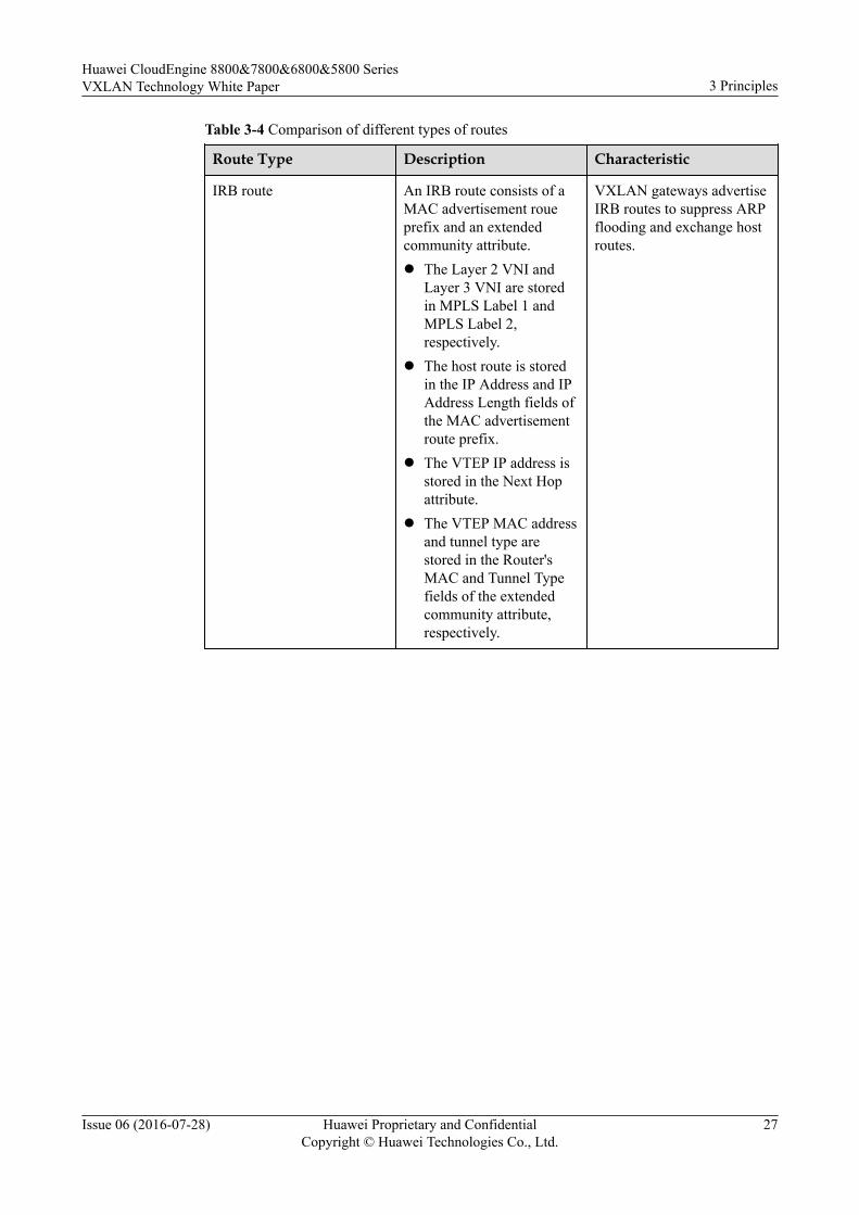
Table 3-4 Comparison of different types of routes
Route Type Description Characteristic
IRB route An IRB route consists of aMAC advertisement roueprefix and an extendedcommunity attribute.l The Layer 2 VNI and
Layer 3 VNI are storedin MPLS Label 1 andMPLS Label 2,respectively.
l The host route is storedin the IP Address and IPAddress Length fields ofthe MAC advertisementroute prefix.
l The VTEP IP address isstored in the Next Hopattribute.
l The VTEP MAC addressand tunnel type arestored in the Router'sMAC and Tunnel Typefields of the extendedcommunity attribute,respectively.
VXLAN gateways advertiseIRB routes to suppress ARPflooding and exchange hostroutes.
Huawei CloudEngine 8800&7800&6800&5800 SeriesVXLAN Technology White Paper 3 Principles
Issue 06 (2016-07-28) Huawei Proprietary and ConfidentialCopyright © Huawei Technologies Co., Ltd.
27

Route Type Description Characteristic
IP prefix route Layer 3 VNIAn IP prefix route consistsof an IP prefix route prefixand an extended communityattribute.l An IP prefix route stores
the Layer 3 VNI inMPLS Label 2, but doesnot carry the Layer 2VNI.
l The host route is storedin the IP Address and IPAddress Length fields ofthe IP prefix route prefix.
l The VTEP IP address isstored in the Next Hopattribute.
l The VTEP MAC addressand tunnel type arestored in the Router'sMAC and Tunnel Typefields of the extendedcommunity attribute,respectively.
VXLAN gateways advertiseIP prefix routes to exchangehost routes or host networksegment routes. If manyhost routes belong to thesame network segment,configure VXLAN gatewaysto advertise host networksegment routes using IPprefix routes. Only one hostnetwork segment route is tobe advertised for host routesbelonging to the samenetwork segment.NOTE
A VXLAN gateway canadvertise network segmentroutes only if the networksegments attached to thegateway are unique network-wide.
A host route or host network segment route is stored in the IP Address and IP Address Lengthfields of a MAC advertisement route prefix or IP prefix route prefix.
Huawei CloudEngine 8800&7800&6800&5800 SeriesVXLAN Technology White Paper 3 Principles
Issue 06 (2016-07-28) Huawei Proprietary and ConfidentialCopyright © Huawei Technologies Co., Ltd.
28
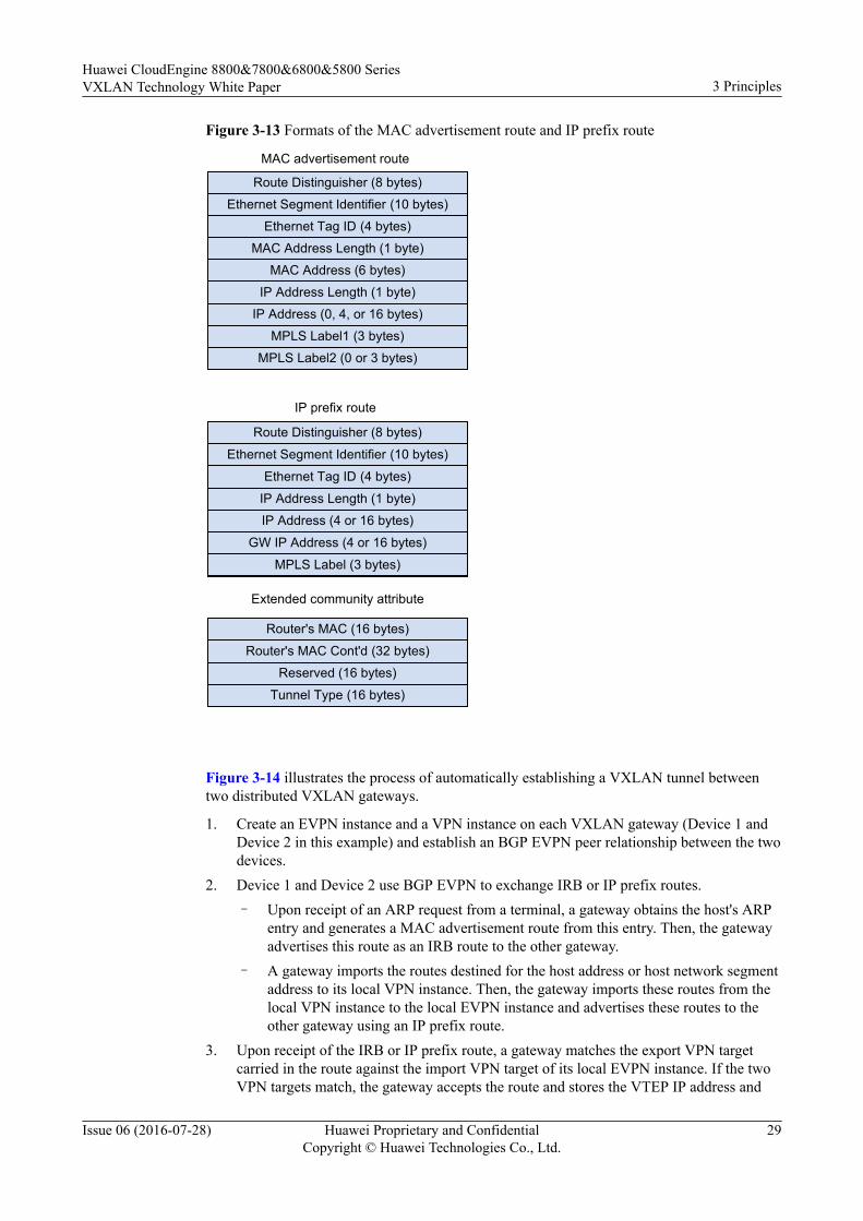
Figure 3-13 Formats of the MAC advertisement route and IP prefix route
Route Distinguisher(8 字节)
Ethernet Segment Identifier (10 字节)
Ethernet Tag ID(4 字节)
IP Address Length(1 字节)
IP Address(4或16 字节)
GW IP Address(4或16 字节)
MPLS Label(3 字节)
Route Distinguisher (8 bytes)
Ethernet Segment Identifier (10 bytes)
Ethernet Tag ID (4 bytes)
MAC Address Length (1 byte)
MAC Address (6 bytes)
IP Address Length (1 byte)
IP Address (0, 4, or 16 bytes)
MPLS Label1 (3 bytes)
MPLS Label2 (0 or 3 bytes)
MAC advertisement route
IP prefix route
Route Distinguisher (8 bytes)
Ethernet Segment Identifier (10 bytes)
Ethernet Tag ID (4 bytes)
IP Address Length (1 byte)
IP Address (4 or 16 bytes)
GW IP Address (4 or 16 bytes)
MPLS Label (3 bytes)
Extended community attribute
Router's MAC (16 bytes)
Router's MAC Cont'd (32 bytes)
Reserved (16 bytes)
Tunnel Type (16 bytes)
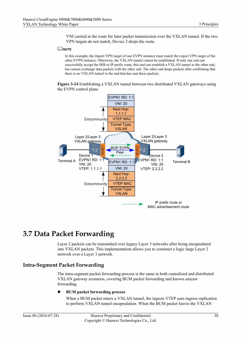
Figure 3-14 illustrates the process of automatically establishing a VXLAN tunnel betweentwo distributed VXLAN gateways.
1. Create an EVPN instance and a VPN instance on each VXLAN gateway (Device 1 andDevice 2 in this example) and establish an BGP EVPN peer relationship between the twodevices.
2. Device 1 and Device 2 use BGP EVPN to exchange IRB or IP prefix routes.– Upon receipt of an ARP request from a terminal, a gateway obtains the host's ARP
entry and generates a MAC advertisement route from this entry. Then, the gatewayadvertises this route as an IRB route to the other gateway.
– A gateway imports the routes destined for the host address or host network segmentaddress to its local VPN instance. Then, the gateway imports these routes from thelocal VPN instance to the local EVPN instance and advertises these routes to theother gateway using an IP prefix route.
3. Upon receipt of the IRB or IP prefix route, a gateway matches the export VPN targetcarried in the route against the import VPN target of its local EVPN instance. If the twoVPN targets match, the gateway accepts the route and stores the VTEP IP address and
Huawei CloudEngine 8800&7800&6800&5800 SeriesVXLAN Technology White Paper 3 Principles
Issue 06 (2016-07-28) Huawei Proprietary and ConfidentialCopyright © Huawei Technologies Co., Ltd.
29
VNI carried in the route for later packet transmission over the VXLAN tunnel. If the twoVPN targets do not match, Device 2 drops the route.
NOTE
In this example, the import VPN target of one EVPN instance must match the export VPN target of theother EVPN instance. Otherwise, the VXLAN tunnel cannot be established. If only one end cansuccessfully accept the IRB or IP prefix route, this end can establish a VXLAN tunnel to the other end,but cannot exchange data packets with the other end. The other end drops packets after confirming thatthere is no VXLAN tunnel to the end that has sent these packets.
Figure 3-14 Establishing a VXLAN tunnel between two distributed VXLAN gateways usingthe EVPN control plane
Terminal B
IP prefix route or MAC advertisement route
Terminal ADevice 1EVPN1 RD: 1:1VNI: 20VTEP: 1.1.1.1
Device 2EVPN1 RD: 1:1
VNI: 20VTEP: 2.2.2.2
Layer 2/Layer 3 VXLAN gateway
Layer 2/Layer 3 VXLAN gateway
BGP EVPNPeer
EVPN1 RD: 1:1
VNI: 20Next Hop:
1.1.1.1 VTEP MAC Tunnel Type:
VXLAN
EVPN1 RD: 1:1
VNI: 20Next Hop:
2.2.2.2 VTEP MACTunnel Type:
VXLAN
Extcommunity
Extcommunity
NVE
1
NV
E2
3.7 Data Packet ForwardingLayer 2 packets can be transmitted over legacy Layer 3 networks after being encapsulatedinto VXLAN packets. This implementation allows you to construct a logic large Layer 2network over a Layer 3 network.
Intra-Segment Packet ForwardingThe intra-segment packet forwarding process is the same in both centralized and distributedVXLAN gateway scenarios, covering BUM packet forwarding and known unicastforwarding.
l BUM packet forwarding processWhen a BUM packet enters a VXLAN tunnel, the ingress VTEP uses ingress replicationto perform VXLAN tunnel encapsulation. When the BUM packet leaves the VXLAN
Huawei CloudEngine 8800&7800&6800&5800 SeriesVXLAN Technology White Paper 3 Principles
Issue 06 (2016-07-28) Huawei Proprietary and ConfidentialCopyright © Huawei Technologies Co., Ltd.
30

tunnel, the egress VTEP decapsulates the BUM packet. Figure 3-15 shows the BUMpacket forwarding process.
NOTE
Ingress replication: After an NVE receives broadcast, unknown unicast, and multicast (BUM)packets, the local VTEP obtains a list of VTEPs on the same VXLAN segment as itself throughthe control plane and sends a copy of the BUM packets to every VTEP in the list.
Ingress replication allows BUM packets to be transmitted in broadcast mode, independent ofmulticast routing protocols.
Huawei CloudEngine 8800&7800&6800&5800 SeriesVXLAN Technology White Paper 3 Principles
Issue 06 (2016-07-28) Huawei Proprietary and ConfidentialCopyright © Huawei Technologies Co., Ltd.
31
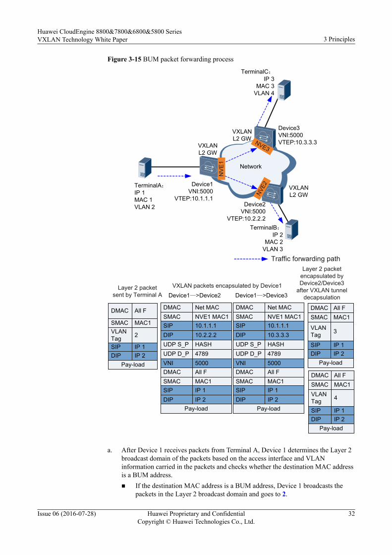
Figure 3-15 BUM packet forwarding process
TerminalA:IP 1MAC 1VLAN 2
Network
Device1VNI:5000
VTEP:10.1.1.1Device2
VNI:5000VTEP:10.2.2.2
TerminalB:IP 2
MAC 2VLAN 3
TerminalC:IP 3
MAC 3VLAN 4
VXLANL2 GW
VXLANL2 GW
VXLANL2 GW
Device3VNI:5000VTEP:10.3.3.3
Traffic forwarding path
Layer 2 packet sent by Terminal A
VXLAN packets encapsulated by Device1
Layer 2 packet encapsulated by Device2/Device3
after VXLAN tunnel decapsulationDevice1—>Device2 Device1—>Device3
SMAC NVE1 MAC1DMAC Net MAC
SIP 10.1.1.1DIP 10.2.2.2UDP S_P HASHUDP D_P 4789VNI 5000
SMAC MAC1DMAC All F
SIP IP 1DIP IP 2
Pay-load
SMAC NVE1 MAC1DMAC Net MAC
SIP 10.1.1.1DIP 10.3.3.3UDP S_P HASHUDP D_P 4789VNI 5000
SMAC MAC1DMAC All F
SIP IP 1DIP IP 2
Pay-load
NVE
1
NVE3
NVE2
DMAC All F
SMAC MAC1VLAN Tag 2
SIP IP 1DIP IP 2
Pay-load
DMAC All FSMAC MAC1
VLAN Tag 3
DMAC All FSMAC MAC1VLAN Tag 4
SIP IP 1DIP IP 2
Pay-load
SIP IP 1DIP IP 2
Pay-load
a. After Device 1 receives packets from Terminal A, Device 1 determines the Layer 2broadcast domain of the packets based on the access interface and VLANinformation carried in the packets and checks whether the destination MAC addressis a BUM address.n If the destination MAC address is a BUM address, Device 1 broadcasts the
packets in the Layer 2 broadcast domain and goes to 2.
Huawei CloudEngine 8800&7800&6800&5800 SeriesVXLAN Technology White Paper 3 Principles
Issue 06 (2016-07-28) Huawei Proprietary and ConfidentialCopyright © Huawei Technologies Co., Ltd.
32
n If the destination MAC address is not a BUM address, Device 1 follows theunicast packet forwarding process.
b. Device 1's VTEP obtains the ingress replication list for the VNI, replicates packetsbased on the list, and performs VXLAN tunnel encapsulation by adding outerheaders. Device 1 then forwards the packets through the outbound interface.
c. Upon receipt of the VXLAN packets, the VTEP on Device 2 or Device 3 verifiesthe VXLAN packets based on the UDP destination port numbers, source anddestination IP addresses, and VNI. The VTEP obtains the Layer 2 broadcast domainbased on the VNI and removes the outer headers to obtain the inner Layer 2packets. It then determines whether the destination MAC address is a BUM address.n If the destination MAC address is a BUM address, the VTEP broadcasts the
packets to the user side in the Layer 2 broadcast domain.n If the destination MAC address is not a BUM address, the VTEP further
checks whether it is a local MAC address.○ If it is a local MAC address, the VTEP sends the packets to the device.○ If it is not a local MAC address, the VTEP searches for the outbound
interface and encapsulation information in the Layer 2 broadcast domainand goes to 4.
d. Device 2 or Device 3 adds VLAN tags to the packets based on the outboundinterface and encapsulation information and forwards the packets to Terminal B orTerminal C.
NOTE
Terminal B or Terminal C responds to Terminal A following the unicast packet forwardingprocess.
l Unicast Packet Forwarding ProcessFigure 3-16 shows the unicast packet forwarding process.
Huawei CloudEngine 8800&7800&6800&5800 SeriesVXLAN Technology White Paper 3 Principles
Issue 06 (2016-07-28) Huawei Proprietary and ConfidentialCopyright © Huawei Technologies Co., Ltd.
33

Figure 3-16 Unicast packet forwarding process
TerminalB:IP 2
MAC 2VLAN 3
Traffic forwarding path
Layer 2 packet sent by Terminal A
VXLAN packet encapsulated by Device1
Layer 2 packet encapsulated by
Device2 after VXLAN tunnel decapsulation
Layer 2 packet sent by Terminal B
VXLAN packet encapsulated by Device2
Layer 2 packet encapsulated by
Device1 after VXLAN tunnel decapsulation
TerminalA:IP 1MAC 1VLAN 2
Network
Device1VNI:5000VTEP:10.1.1.1
Device2VNI:5000
VTEP:10.2.2.2
VXLANL2 GW
VXLANL2 GW
DMAC MAC1SMAC MAC2VLAN Tag 2
SMAC NVE1 MAC1DMAC Net MAC
SIP 10.1.1.1DIP 10.2.2.2UDP S_P HASHUDP D_P 4789VNI 5000
SMAC MAC1DMAC MAC2
SIP IP 1DIP IP 2
Pay-load
SMAC NVE2 MAC1DMAC Net MAC
SIP 10.2.2.2DIP 10.1.1.1UDP S_P HASHUDP D_P 4789VNI 5000
SMAC MAC2DMAC MAC1
SIP IP 2DIP IP 1
Pay-load
DMAC MAC2SMAC MAC1
VLAN Tag 3
DMAC MAC2SMAC MAC1VLAN Tag 2
DMAC MAC1SMAC MAC2
VLAN Tag 3
NV
E1
NVE
2
a. After Device 1 receives packets from Terminal A, Device 1 determines the Layer 2broadcast domain of the packets based on the access interface and VLANinformation carried in the packets and checks whether the destination MAC addressis a unicast address.n If the destination MAC address is a unicast address, Device 1 further checks
whether it is a local MAC address.○ If it is a local MAC address, Device 1 processes the packets.
Huawei CloudEngine 8800&7800&6800&5800 SeriesVXLAN Technology White Paper 3 Principles
Issue 06 (2016-07-28) Huawei Proprietary and ConfidentialCopyright © Huawei Technologies Co., Ltd.
34
○ If it is not a local MAC address, Device 1 searches for the outboundinterface and encapsulation information in the Layer 2 broadcast domainand goes to 2.
n If the destination MAC address is not a unicast address, the VTEP follows the2.
b. Device 1's VTEP performs VXLAN tunnel encapsulation based on the outboundinterface and encapsulation information and forwards the packets.
c. Upon receipt of the VXLAN packets, Device 2's VTEP verifies the VXLANpackets based on the UDP destination port numbers, source and destination IPaddresses, and VNI. Device 2 obtains the Layer 2 broadcast domain based on theVNI and performs VXLAN tunnel decapsulation to obtain the inner Layer 2packets. It then determines whether the destination MAC address is a unicastaddress.n If the destination MAC address is a unicast address, the VTEP searches for the
outbound interface and encapsulation information in the Layer 2 broadcastdomain and goes to 4.
n If the destination MAC address is not a unicast address, the VTEP furtherchecks whether it is a local MAC address.○ If it is a local MAC address, the VTEP sends the packets to Device 2.○ If it is not a local MAC address, the VTEP follows the BUM packet
forwarding process.d. Device 2 adds VLAN tags to the packets based on the outbound interface and
encapsulation information and forwards the packets to Terminal B.
Inter-Segment Packet ForwardingThe inter-segment packet forwarding process varies in centralized and distributed VXLANgateway scenarios.
l Centralized VXLAN gatewayVNIs can be mapped to BDs in 1:1 mode so that a BD can function as a VXLANnetwork entity to transmit VXLAN data packets. Layer 3 VBDIF interfaces can beconfigured for BDs. VBDIF interfaces have similar functions as VLANIF interfaces.Configuring IP addresses for VBDIF interfaces allows communication betweenVXLANs on different network segments and between VXLANs and non-VXLANs,implementing VXLAN Layer 3 gateway functionality.
Huawei CloudEngine 8800&7800&6800&5800 SeriesVXLAN Technology White Paper 3 Principles
Issue 06 (2016-07-28) Huawei Proprietary and ConfidentialCopyright © Huawei Technologies Co., Ltd.
35
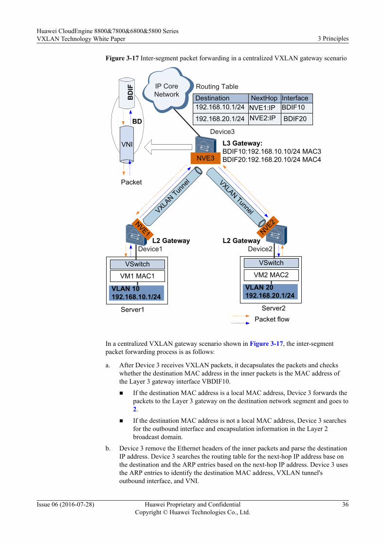
Figure 3-17 Inter-segment packet forwarding in a centralized VXLAN gateway scenario
NVE2:IP
Device2Device1
Server1 Server2
VLAN 10192.168.10.1/24
VLAN 20192.168.20.1/24
VM1 MAC1 VM2 MAC2VSwitch VSwitch
Device3
L3 Gateway:BDIF10:192.168.10.10/24 MAC3BDIF20:192.168.20.10/24 MAC4
VNI
BDB
DIF
Packet
BDIF10Interface
192.168.20.1/24NVE1:IP192.168.10.1/24NextHopDestination
BDIF20
Routing TableIP Core Network
L2 Gateway L2 Gateway
Packet flow
VXLAN Tun
nel VXLAN Tunnel
NVE3
NVE2NVE1
In a centralized VXLAN gateway scenario shown in Figure 3-17, the inter-segmentpacket forwarding process is as follows:
a. After Device 3 receives VXLAN packets, it decapsulates the packets and checkswhether the destination MAC address in the inner packets is the MAC address ofthe Layer 3 gateway interface VBDIF10.
n If the destination MAC address is a local MAC address, Device 3 forwards thepackets to the Layer 3 gateway on the destination network segment and goes to2.
n If the destination MAC address is not a local MAC address, Device 3 searchesfor the outbound interface and encapsulation information in the Layer 2broadcast domain.
b. Device 3 remove the Ethernet headers of the inner packets and parse the destinationIP address. Device 3 searches the routing table for the next-hop IP address base onthe destination and the ARP entries based on the next-hop IP address. Device 3 usesthe ARP entries to identify the destination MAC address, VXLAN tunnel'soutbound interface, and VNI.
Huawei CloudEngine 8800&7800&6800&5800 SeriesVXLAN Technology White Paper 3 Principles
Issue 06 (2016-07-28) Huawei Proprietary and ConfidentialCopyright © Huawei Technologies Co., Ltd.
36
n If the VXLAN tunnel's outbound interface and VNI cannot be found, Device 3performs Layer 3 forwarding.
n If the VXLAN tunnel's outbound interface and VNI can be found, Device 3follows 3.
c. Device 3 encapsulate VXLAN packets again, with the source MAC address in theEthernet header of the inner packets as the MAC address of the Layer 3 gatewayinterface VBDIF20.
NOTE
For details on communication between Device 3 and other devices, see Layer 2 gatewayprinciples.
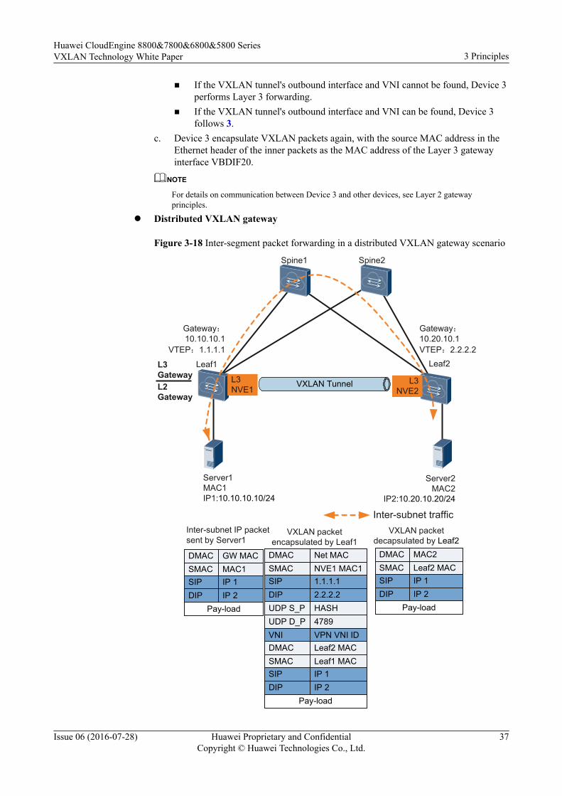
l Distributed VXLAN gateway
Figure 3-18 Inter-segment packet forwarding in a distributed VXLAN gateway scenario
Spine1 Spine2
Leaf1 Leaf2
Server1MAC1IP1:10.10.10.10/24
Server2MAC2
IP2:10.20.10.20/24
Gateway:10.10.10.1
VTEP:1.1.1.1
Gateway:10.20.10.1VTEP:2.2.2.2
VXLAN Tunnel
L3 GatewayL2 Gateway
SMAC NVE1 MAC1DMAC Net MAC
SIP 1.1.1.1DIP 2.2.2.2UDP S_P HASHUDP D_P 4789VNI VPN VNI ID
SMAC Leaf1 MACDMAC Leaf2 MAC
SIP IP 1DIP IP 2
SMAC MAC1DMAC GW MAC
SIP IP 1DIP IP 2
Pay-load
Pay-load
SMAC Leaf2 MACDMAC MAC2
SIP IP 1DIP IP 2
Pay-load
Inter-subnet IP packet sent by Server1
VXLAN packet encapsulated by Leaf1
VXLAN packet decapsulated by Leaf2
Inter-subnet traffic
L3 NVE1
L3 NVE2
Huawei CloudEngine 8800&7800&6800&5800 SeriesVXLAN Technology White Paper 3 Principles
Issue 06 (2016-07-28) Huawei Proprietary and ConfidentialCopyright © Huawei Technologies Co., Ltd.
37
In a distributed VXLAN gateway scenario shown in Figure 3-18, the inter-segmentpacket forwarding process is as follows:
a. After Leaf1 receives IP packets from Server 1 to Server 2 on a different subnet,Leaf1 performs VXLAN encapsulation. Specifically, Leaf1 maps Server 1's subnetVNI to its VPN instance's VNI and finds the gateway's outbound interface of Server1's IP packets. Leaf1 then forwards the packets at Layer 3 based on the VPNinstance bound to the gateway's outbound interface, with the host route's next hopaddress being Leaf2's VTEP address.
b. After Leaf2 receives the VXLAN packets, it decapsulates the VXLAN packets.Specifically, Leaf2 maps the VNI to a VPN instance, searches a host route in theVPN, and replaces the Ethernet header. Leaf2 then sends the packets to thedestination host Server 2.
3.8 ARP Broadcast SuppressionWhen tenants access each other for the first time, they send ARP requests. These ARPrequests are broadcast on Layer 2 networks, which may cause a broadcast storm. To preventthis problem, ARP broadcast suppression can be enabled on Layer 2 VXLAN gateways.
Huawei CloudEngine 8800&7800&6800&5800 SeriesVXLAN Technology White Paper 3 Principles
Issue 06 (2016-07-28) Huawei Proprietary and ConfidentialCopyright © Huawei Technologies Co., Ltd.
38
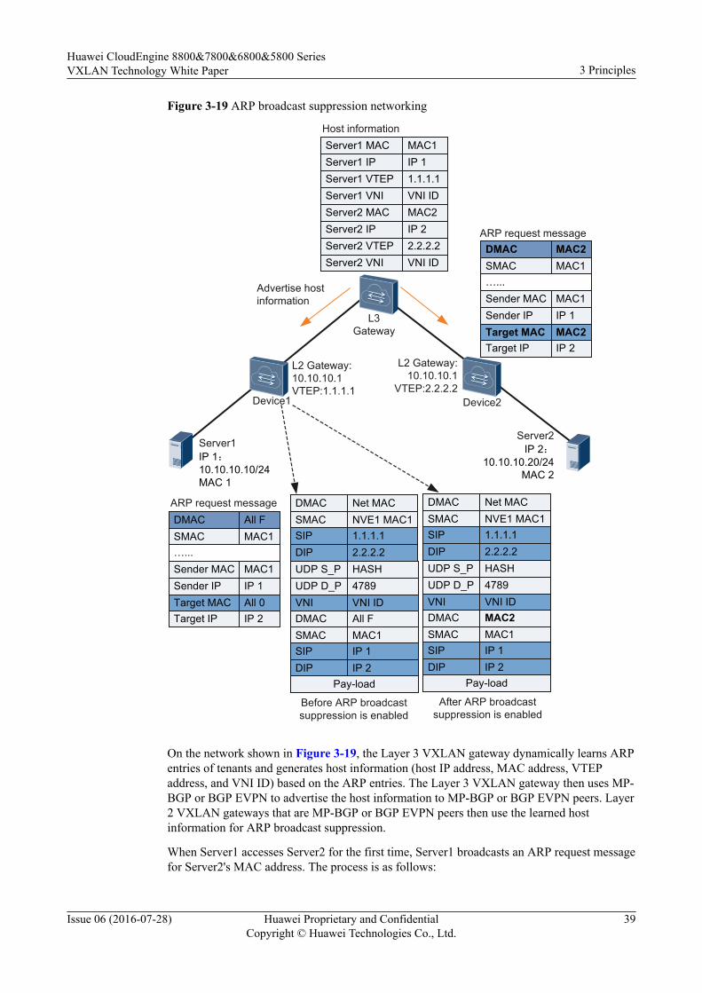
Figure 3-19 ARP broadcast suppression networking
SMAC NVE1 MAC1DMAC Net MAC
SIP 1.1.1.1DIP 2.2.2.2UDP S_P HASHUDP D_P 4789VNI VNI ID
SMAC MAC1DMAC All F
SIP IP 1DIP IP 2
Pay-load
L2 Gateway:10.10.10.1VTEP:1.1.1.1
Server1IP 1:10.10.10.10/24MAC 1
Server2IP 2:
10.10.10.20/24MAC 2
L2 Gateway:10.10.10.1
VTEP:2.2.2.2
Server1 IPServer1 VTEP
Server1 MAC
Server1 VNI
IP 11.1.1.1
MAC1
VNI ID
L3 Gateway
SMAC NVE1 MAC1DMAC Net MAC
SIP 1.1.1.1DIP 2.2.2.2UDP S_P HASHUDP D_P 4789VNI VNI ID
SMAC MAC1DMAC MAC2
SIP IP 1DIP IP 2
Pay-load
Server2 IPServer2 VTEP
Server2 MAC
Server2 VNI
IP 22.2.2.2
MAC2
VNI ID
Device1 Device2
SMAC MAC1DMAC All F
…...Sender MAC MAC1Sender IP IP 1Target MAC All 0Target IP IP 2
SMAC MAC1DMAC MAC2
…...Sender MAC MAC1Sender IP IP 1Target MAC MAC2Target IP IP 2
Host information
Advertise host information
ARP request message
ARP request message
Before ARP broadcast suppression is enabled
After ARP broadcast suppression is enabled
On the network shown in Figure 3-19, the Layer 3 VXLAN gateway dynamically learns ARPentries of tenants and generates host information (host IP address, MAC address, VTEPaddress, and VNI ID) based on the ARP entries. The Layer 3 VXLAN gateway then uses MP-BGP or BGP EVPN to advertise the host information to MP-BGP or BGP EVPN peers. Layer2 VXLAN gateways that are MP-BGP or BGP EVPN peers then use the learned hostinformation for ARP broadcast suppression.
When Server1 accesses Server2 for the first time, Server1 broadcasts an ARP request messagefor Server2's MAC address. The process is as follows:
Huawei CloudEngine 8800&7800&6800&5800 SeriesVXLAN Technology White Paper 3 Principles
Issue 06 (2016-07-28) Huawei Proprietary and ConfidentialCopyright © Huawei Technologies Co., Ltd.
39
1. Server1 broadcasts an ARP request message for Server2's MAC address.2. Device1, a Layer 2 VXLAN gateway, receives the ARP request message and searches
host information.– If the host information on Device1 contains Server2 information, Device1 replaces
the destination MAC address and target MAC in the broadcast ARP requestmessage with Server2's MAC address, performs VXLAN encapsulation, andforwards the VXLAN packet.
– If the host information on Device1 does not contain Server2 information, Device1retains the destination MAC address in the broadcast ARP request message,performs VXLAN encapsulation, and forwards the VXLAN packet.
3. After Device2, a Layer 2 VXLAN gateway, receives the VXLAN packet, it performsVXLAN decapsulation and obtains the ARP request message. Device2 then determineswhether the destination MAC address in the ARP request message is a broadcast MACaddress.– If the destination MAC address is a broadcast address, Device2 broadcasts the ARP
request message to the user side in the Layer 2 broadcast domain.– If the destination MAC address is not a broadcast address, Device2 forwards the
ARP request message to the destination host Server2.4. Server2 receives the ARP request message and responds with an ARP reply message.5. Server1 receives the ARP reply message and generates an ARP entry in the ARP cache.
By now, Server1 can communicate with Server2.
3.9 All-Active VXLAN Gateway
BackgroundMultiple gateways are often deployed on a VXLAN network to improve reliability. When onegateway fails, traffic can be rapidly switched to another gateway. This prevents serviceinterruptions.
VRRP can be used to improve the reliability. In VRRP networking, only the active gatewaycan forward traffic and provide the gateway service. The standby gateway provides thegateway service only after the active gateway fails. The switchover mechanism reducesgateway usage and slows down convergence. It is required that reliability be guaranteed andmultiple gateways be used to forward traffic to make full use of gateway resources.
Huawei CloudEngine 8800&7800&6800&5800 SeriesVXLAN Technology White Paper 3 Principles
Issue 06 (2016-07-28) Huawei Proprietary and ConfidentialCopyright © Huawei Technologies Co., Ltd.
40

Figure 3-20 Centralized all-active VXLAN gateway
Leaf1 Leaf2 Leaf3 Leaf4
Spine1 Spine2
Campus egress
...
Security resource pool
vVTEP
Centralized all-active VXLAN gateway can be deployed to meet the preceding requirements.In typical networking composed of spine and leaf switches, the same VTEP address isconfigured for spine switches to simulate them into one VTEP, and then all spine switches areconfigured with Layer 3 gateway. Regardless of the spine switch to which traffic is sent, thespine switch can provide the gateway service and correctly forward packets to the next-hopdevice. Similarly, regardless of the spine switch to which external traffic is sent, traffic can becorrectly forwarded to hosts. As shown in Figure 3-20, Spine1 and Spine2 are configuredwith centralized all-active VXLAN gateway so that Spine1 and Spine2 can forward trafficsimultaneously. This function improves the device resource usage and convergenceperformance.
When centralized all-active VXLAN gateway is deployed, the spine switch functions as theLayer 3 gateway. Entries of tenants whose packets are forwarded at Layer 3 are generated onthe spine switch, whereas the space of the spine switch is limited. When more and more VMsor servers are deployed, the spine switch may become the bottleneck.
Concepts
In Figure 3-20, the concepts relevant to centralized all-active VXLAN gateway are describedas follows:l Spine
Layer 3 gateway on a VXLAN network. The spine switch decapsulates VXLAN packetsand forwards them again, and allows servers or VMs between subnets to communicateand physical servers and VMs to communicate with the external network.
l LeafLayer 2 access device on a VXLAN network. The leaf switch connects to a physicalserver or VM, encapsulates packets from physical servers and VMs into VXLANpackets, and transmits them on the VXLAN network.
Huawei CloudEngine 8800&7800&6800&5800 SeriesVXLAN Technology White Paper 3 Principles
Issue 06 (2016-07-28) Huawei Proprietary and ConfidentialCopyright © Huawei Technologies Co., Ltd.
41
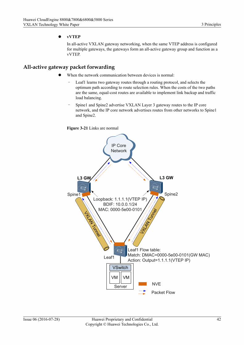
l vVTEPIn all-active VXLAN gateway networking, when the same VTEP address is configuredfor multiple gateways, the gateways form an all-active gateway group and function as avVTEP.
All-active gateway packet forwardingl When the network communication between devices is normal:
– Leaf1 learns two gateway routes through a routing protocol, and selects theoptimum path according to route selection rules. When the costs of the two pathsare the same, equal-cost routes are available to implement link backup and trafficload balancing.
– Spine1 and Spine2 advertise VXLAN Layer 3 gateway routes to the IP corenetwork, and the IP core network advertises routes from other networks to Spine1and Spine2.
Figure 3-21 Links are normal
VXLAN Tunnel
VM VM
VSwitch
Server
IP Core Network
VXLA
N Tu
nnel
NVE
L3 GW
Leaf1 Flow table:Match: DMAC=0000-5e00-0101(GW MAC)Action: Output=1.1.1.1(VTEP IP)
Loopback: 1.1.1.1(VTEP IP)BDIF: 10.0.0.1/24
MAC: 0000-5e00-0101
L3 GW
Packet Flow
Leaf1
Spine1 Spine2
Huawei CloudEngine 8800&7800&6800&5800 SeriesVXLAN Technology White Paper 3 Principles
Issue 06 (2016-07-28) Huawei Proprietary and ConfidentialCopyright © Huawei Technologies Co., Ltd.
42
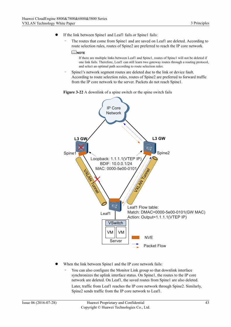
l If the link between Spine1 and Leaf1 fails or Spine1 fails:– The routes that come from Spine1 and are saved on Leaf1 are deleted. According to
route selection rules, routes of Spine2 are preferred to reach the IP core network.NOTE
If there are multiple links between Leaf1 and Spine1, routes of Spine1 will not be deleted ifone link fails. Therefore, Leaf1 can still learn two gateway routes through a routing protocol,and select an optimal path according to route selection rules.
– Spine1's network segment routes are deleted due to the link or device fault.According to route selection rules, routes of Spine2 are preferred to forward trafficfrom the IP core network to the server. Packets do not reach Spine1.
Figure 3-22 A downlink of a spine switch or the spine switch fails
VXLAN Tunnel
VM VM
VSwitch
Server
IP Core Network
VXLA
N Tu
nnel
NVE
L3 GW
Leaf1 Flow table:Match: DMAC=0000-5e00-0101(GW MAC)Action: Output=1.1.1.1(VTEP IP)
Loopback: 1.1.1.1(VTEP IP)BDIF: 10.0.0.1/24
MAC: 0000-5e00-0101
L3 GW
Packet Flow
Leaf1
Spine1 Spine2
l When the link between Spine1 and the IP core network fails:
– You can also configure the Monitor Link group so that downlink interfacesynchronizes the uplink interface status. On Spine1, the routes to the IP corenetwork are deleted. On Leaf1, the saved routes from Spine1 are also deleted.Later, traffic from Leaf1 reaches the IP core network through Spine2. Similarly,Spine2 sends traffic from the IP core network to Leaf1.
Huawei CloudEngine 8800&7800&6800&5800 SeriesVXLAN Technology White Paper 3 Principles
Issue 06 (2016-07-28) Huawei Proprietary and ConfidentialCopyright © Huawei Technologies Co., Ltd.
43

– The open programmability system (OPS) mechanism can also be used to runPython scripts on devices. When Spine1 detects an uplink fault, Spine1automatically decreases the priority of the advertised VTEP host route, so that alltraffic is bypassed to Spine2. After the uplink fault recovers, Spine1 automaticallyrestores the priority of the advertised VTEP host route, so that traffic is loadbalanced between Spine1 and Spine2. This method can implement smooth faultrecovery.
Figure 3-23 An uplink of a spine switch fails
VXLAN Tunnel
VM VM
VSwitch
Server
IP Core Network
VXLA
N Tu
nnel
NVE
L3 GW
Leaf1 Flow table:Match: DMAC=0000-5e00-0101(GW MAC)Action: Output=1.1.1.1(VTEP IP)
Loopback: 1.1.1.1(VTEP IP)BDIF: 10.0.0.1/24
MAC: 0000-5e00-0101
L3 GW
Packet Flow
Leaf1
Spine1 Spine2
ARP Entry SynchronizationIn an all-active gateway scenario, multiple gateways advertise routes of the same subnet to theupper-layer routing device so that the upper-layer routing device has equal-cost routes to thespecified network segment. Traffic from the upper-layer routing device is sent to a gatewaythrough an equal-cost route. If there is no ARP entry of the destination host on the gateway,ARP packets are flooded and traffic is discarded.
To ensure correct traffic forwarding, all-active gateways must synchronize ARP entries. Thatis, when any host in the subnet where a gateway is deployed goes online, all gateways learn
Huawei CloudEngine 8800&7800&6800&5800 SeriesVXLAN Technology White Paper 3 Principles
Issue 06 (2016-07-28) Huawei Proprietary and ConfidentialCopyright © Huawei Technologies Co., Ltd.
44

the ARP entry of the host. The device provides the following modes to implement ARP entrysynchronization:l Controller mode: On all-active gateways, dynamic ARP learning is disabled on their
VBDIF interfaces. The controller manages and controls ARP entries uniformly. When ahost goes online, the controller obtains the ARP entry of the host and delivers the ARPentry to all-active gateways.
l Single-node mode: The device automatically learns ARP entries, but does not depend onthe controller. The working mechanism is as follows:
a. A user specifies the IP addresses of all neighbors of a gateway in a DFS group, sothat the gateway establishes neighbor relationships with devices with specified IPaddresses.
b. After neighbor relationships are established, the gateways synchronize ARP entriesfrom each other.Two methods are available for synchronizing ARP entries:n Real-time synchronization: After receiving an ARP request packet, a gateway
synchronizes the new entry or the change to an existing entry to othergateways to ensure ARP entry consistency on the gateways.
n Batch synchronization: A gateway working for a period synchronizes its largenumber of ARP entries to a new gateway or an existing gateway that recoversfrom a fault in a batch.
3.10 VXLAN Dual-Active Access
BackgroundTo improve reliability, servers are often dual-homed to a VXLAN network through doublenetwork adapters. When one network adapter of a server fails, services are not interrupted.
In the preceding scenario, only the active network adapter can receive and send packets,whereas the standby network adapter cannot. This results in a waste of the network adapterand link bandwidth. Two network adapters are required to work in dual-active mode toforward traffic simultaneously, making full use of network adapters and bandwidth resources.
The following problems may occur:l The server may receive the same traffic from two upstream devices connected to it.l The network device that communicates with the server continuously receives traffic from
two devices, causing frequent MAC address flapping on the network device.
Huawei CloudEngine 8800&7800&6800&5800 SeriesVXLAN Technology White Paper 3 Principles
Issue 06 (2016-07-28) Huawei Proprietary and ConfidentialCopyright © Huawei Technologies Co., Ltd.
45
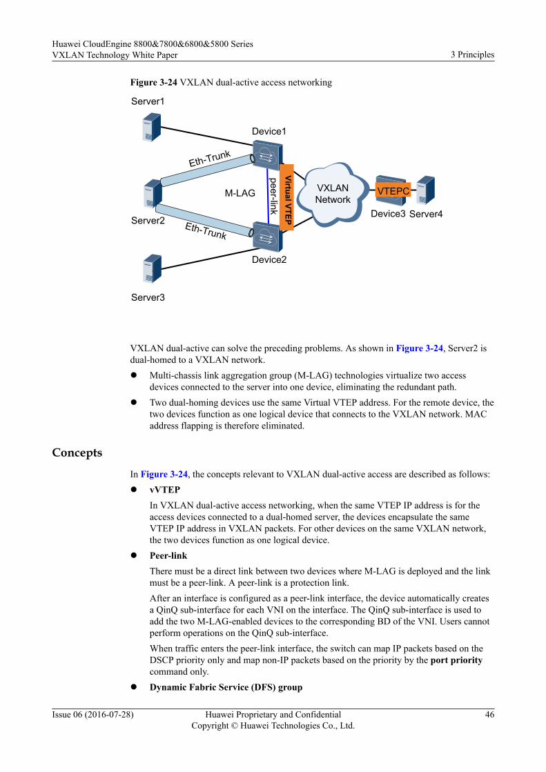
Figure 3-24 VXLAN dual-active access networking
Eth-Trunk
VXLANNetwork
Device1
Eth-Trunk
peer-link
Server2
Device2
Server1
Server3
Virtual VTEP Server4Device3
VTEPCM-LAG
VXLAN dual-active can solve the preceding problems. As shown in Figure 3-24, Server2 isdual-homed to a VXLAN network.l Multi-chassis link aggregation group (M-LAG) technologies virtualize two access
devices connected to the server into one device, eliminating the redundant path.l Two dual-homing devices use the same Virtual VTEP address. For the remote device, the
two devices function as one logical device that connects to the VXLAN network. MACaddress flapping is therefore eliminated.
Concepts
In Figure 3-24, the concepts relevant to VXLAN dual-active access are described as follows:l vVTEP
In VXLAN dual-active access networking, when the same VTEP IP address is for theaccess devices connected to a dual-homed server, the devices encapsulate the sameVTEP IP address in VXLAN packets. For other devices on the same VXLAN network,the two devices function as one logical device.
l Peer-linkThere must be a direct link between two devices where M-LAG is deployed and the linkmust be a peer-link. A peer-link is a protection link.After an interface is configured as a peer-link interface, the device automatically createsa QinQ sub-interface for each VNI on the interface. The QinQ sub-interface is used toadd the two M-LAG-enabled devices to the corresponding BD of the VNI. Users cannotperform operations on the QinQ sub-interface.When traffic enters the peer-link interface, the switch can map IP packets based on theDSCP priority only and map non-IP packets based on the priority by the port prioritycommand only.
l Dynamic Fabric Service (DFS) group
Huawei CloudEngine 8800&7800&6800&5800 SeriesVXLAN Technology White Paper 3 Principles
Issue 06 (2016-07-28) Huawei Proprietary and ConfidentialCopyright © Huawei Technologies Co., Ltd.
46
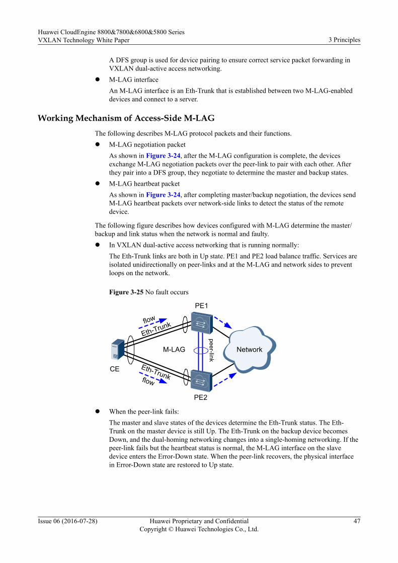
A DFS group is used for device pairing to ensure correct service packet forwarding inVXLAN dual-active access networking.
l M-LAG interfaceAn M-LAG interface is an Eth-Trunk that is established between two M-LAG-enableddevices and connect to a server.
Working Mechanism of Access-Side M-LAGThe following describes M-LAG protocol packets and their functions.l M-LAG negotiation packet
As shown in Figure 3-24, after the M-LAG configuration is complete, the devicesexchange M-LAG negotiation packets over the peer-link to pair with each other. Afterthey pair into a DFS group, they negotiate to determine the master and backup states.
l M-LAG heartbeat packetAs shown in Figure 3-24, after completing master/backup negotiation, the devices sendM-LAG heartbeat packets over network-side links to detect the status of the remotedevice.
The following figure describes how devices configured with M-LAG determine the master/backup and link status when the network is normal and faulty.l In VXLAN dual-active access networking that is running normally:
The Eth-Trunk links are both in Up state. PE1 and PE2 load balance traffic. Services areisolated unidirectionally on peer-links and at the M-LAG and network sides to preventloops on the network.
Figure 3-25 No fault occurs
Network
PE1
Eth-TrunkCE
PE2
M-LAG
peer-link
Eth-Trunkflow
flow
l When the peer-link fails:The master and slave states of the devices determine the Eth-Trunk status. The Eth-Trunk on the master device is still Up. The Eth-Trunk on the backup device becomesDown, and the dual-homing networking changes into a single-homing networking. If thepeer-link fails but the heartbeat status is normal, the M-LAG interface on the slavedevice enters the Error-Down state. When the peer-link recovers, the physical interfacein Error-Down state are restored to Up state.
Huawei CloudEngine 8800&7800&6800&5800 SeriesVXLAN Technology White Paper 3 Principles
Issue 06 (2016-07-28) Huawei Proprietary and ConfidentialCopyright © Huawei Technologies Co., Ltd.
47
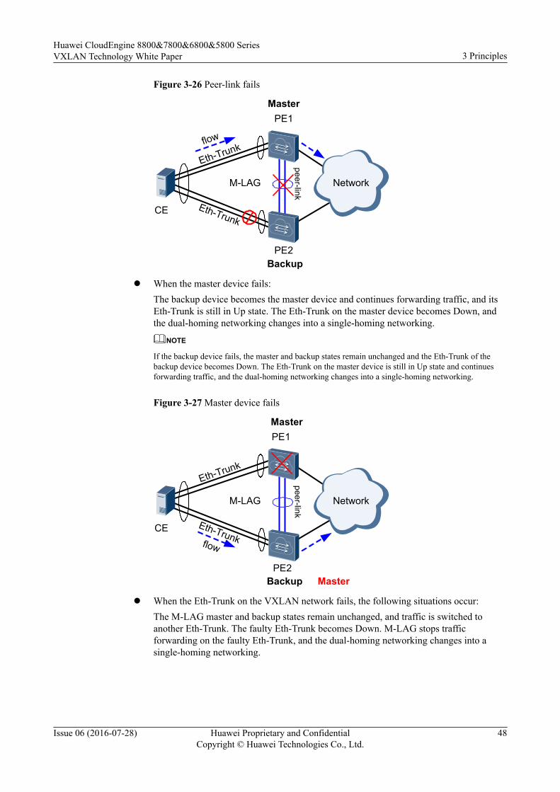
Figure 3-26 Peer-link fails
Network
PE1
Eth-TrunkCE
PE2
M-LAG
peer-link
Eth-Trunk
Master
Backup
flow
l When the master device fails:The backup device becomes the master device and continues forwarding traffic, and itsEth-Trunk is still in Up state. The Eth-Trunk on the master device becomes Down, andthe dual-homing networking changes into a single-homing networking.
NOTE
If the backup device fails, the master and backup states remain unchanged and the Eth-Trunk of thebackup device becomes Down. The Eth-Trunk on the master device is still in Up state and continuesforwarding traffic, and the dual-homing networking changes into a single-homing networking.
Figure 3-27 Master device fails
Network
PE1
Eth-TrunkCE
PE2
M-LAG
peer-link
Eth-Trunk
flow
Backup Master
Master
l When the Eth-Trunk on the VXLAN network fails, the following situations occur:The M-LAG master and backup states remain unchanged, and traffic is switched toanother Eth-Trunk. The faulty Eth-Trunk becomes Down. M-LAG stops trafficforwarding on the faulty Eth-Trunk, and the dual-homing networking changes into asingle-homing networking.
Huawei CloudEngine 8800&7800&6800&5800 SeriesVXLAN Technology White Paper 3 Principles
Issue 06 (2016-07-28) Huawei Proprietary and ConfidentialCopyright © Huawei Technologies Co., Ltd.
48
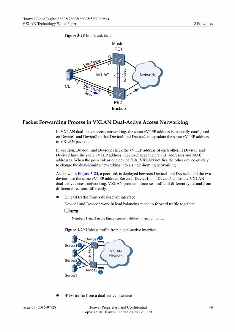
Figure 3-28 Eth-Trunk fails
Network
PE1
Eth-TrunkCE
PE2
M-LAG
peer-link
Eth-Trunk
flow
Backup
Master
Packet Forwarding Process in VXLAN Dual-Active Access Networking
In VXLAN dual-active access networking, the same vVTEP address is manually configuredon Device1 and Device2 so that Device1 and Device2 encapsulate the same vVTEP addressin VXLAN packets.
In addition, Device1 and Device2 check the vVTEP address of each other. If Device1 andDevice2 have the same vVTEP address, they exchange their VTEP addresses and MACaddresses. When the peer-link or one device fails, VXLAN notifies the other device quicklyto change the dual-homing networking into a single-homing networking.
As shown in Figure 3-24, a peer-link is deployed between Device1 and Device2, and the twodevices use the same vVTEP address. Server2, Device1, and Device2 constitute VXLANdual-active access networking. VXLAN protocol processes traffic of different types and fromdifferent directions differently.
l Unicast traffic from a dual-active interfaceDevice1 and Device2 work in load balancing mode to forward traffic together.
NOTE
Numbers 1 and 2 in the figure represent different types of traffic.
Figure 3-29 Unicast traffic from a dual-active interface
Device1
Device2
Peer-link
VXLANNetwork
1
1
2
2
Server1
Server2
Server3
l BUM traffic from a dual-active interface
Huawei CloudEngine 8800&7800&6800&5800 SeriesVXLAN Technology White Paper 3 Principles
Issue 06 (2016-07-28) Huawei Proprietary and ConfidentialCopyright © Huawei Technologies Co., Ltd.
49

BUM traffic from Server2 is load balanced between Device1 and Device2. Thefollowing uses the forwarding process on Device1 as an example.Device1 encapsulates the vVTEP address into the received BUM traffic and forwards thetraffic to each next-hop device. When the traffic arrives at Device2, Device2 forwardsthe traffic only to Server3 but not to Server2 or the VXLAN network side according tothe unidirectional isolation mechanism.
Figure 3-30 BUM traffic from a dual-active interface
Device1
Device2
Peer-link
VXLANNetwork
Server1
Server2
Server3
l Unicast traffic from the VXLAN network
If the unicast traffic is sent to a dual-active interface, traffic is encapsulated with thevVTEP address and is load balanced between Device1 and Device2, which then forwardthe traffic to the attached dual-homed device.
Figure 3-31 Unicast traffic from the VXLAN network
Device1
Device2
Peer-link
VXLANNetwork
Server1
Server2
Server3
l BUM traffic from the VXLAN network
The BUM traffic that is sent to a dual-active interface and encapsulated with the vVTEPaddress is load balanced between Device1 and Device2. The following uses Device1 asan example.Device1 decapsulates the traffic and then forwards the traffic to each user-side interface.Because the peer-link is isolated from the backup interface, traffic arriving at Device2 isnot forwarded to Server2, avoiding routing loops.
Huawei CloudEngine 8800&7800&6800&5800 SeriesVXLAN Technology White Paper 3 Principles
Issue 06 (2016-07-28) Huawei Proprietary and ConfidentialCopyright © Huawei Technologies Co., Ltd.
50

Figure 3-32 BUM traffic from the VXLAN network
Device1
Device2
Peer-link
VXLANNetwork
Server1
Server2
Server3
3.11 Application for Inter-Domain Active-Active VXLANGateways
BackgroundWith the fast development of mobile Internet, data centers provide increasingly diversifiedservices and carry explosively growing traffic. Users become more sensitive to serviceinterruptions caused by failures or inefficient maintenance on computing, storage, or networkdevices.
In legacy networking, inter-domain applications are widely used. To ensure service continuity,implementing inter-domain VXLAN interconnection is of great importance.
Inter-domain communication can be implemented across DCs or across points of delivery(PODs) in the same data center.
Inter-domain active-active VXLAN gateways allow inter-domain communication betweenhosts on different network segments and inter-domain VM migration. In each domain, twoactive VXLAN gateways are deployed to balance or back up traffic for higher networkreliability.
On the network shown in Figure 3-33, Device 1 is dual-homed to Layer 3 gateways Device 3and Device 4 through VXLAN tunnels in POD1; Device 2 is dual-homed to Layer 3 gatewaysDevice 5 and Device 6 through VXLAN tunnels in POD2; Device 1 and Device 2 alsoestablish a VXLAN tunnel for intra-segment communication. The four Layer 3 gateways(Device 3, Device 4, Device 5, and Device 6) have the same MAC address and Layer 2VTEP's IP address, allowing them to function as the same VTEP. This VTEP providesgateway services for traffic sent to any gateway among them.
Huawei CloudEngine 8800&7800&6800&5800 SeriesVXLAN Technology White Paper 3 Principles
Issue 06 (2016-07-28) Huawei Proprietary and ConfidentialCopyright © Huawei Technologies Co., Ltd.
51

Figure 3-33 Inter-domain active-active VXLAN gateways
Device 1
POD1
VXLAN tunnel Device 2
Network
H1 H2
VTEP: 2.2.2.2 VTEP: 3.3.3.3
VXLAN tunnel VXLA
N tu
nnel VXLAN tunnel
VXLA
N tu
nnel
POD2
VTEP: 1.1.1.1 VTEP: 1.1.1.1
NVEActual data
VXLAN data
Device 3 Device 4 Device 5 Device 6
10.1.1.3/24
H3
10.1.1.1/24 10.1.1.2/24
Inter-domain active-active VXLAN gateways can be deployed in the following scenarios:
l Inter-domain communication between hosts on the same network segment (using knownunicast packets or BUM packets)
l Inter-domain communication between hosts on different network segments
l Inter-domain VM migration
Inter-Domain Communication Between Hosts on the Same Network Segment
The forwarding process for known unicast packets on the same network segment in differentdomains is the same as that for known unicast packets on the same network segment in thesame domain.
As shown in Figure 3-33, H1 and H3 reside on the same network segment but in differentPODs. When H1 sends a known unicast data packet to H3, the packet forwarding process is asfollows:
1. After Device 1 receives H1's packet, it determines the Layer 2 BD of the packet based onthe access interface and VLAN information and searches for the outbound interface andencapsulation information in the BD.
2. Device 1's VTEP performs VXLAN encapsulation based on the outbound interface andencapsulation information and forwards the packet to Device 3.
Huawei CloudEngine 8800&7800&6800&5800 SeriesVXLAN Technology White Paper 3 Principles
Issue 06 (2016-07-28) Huawei Proprietary and ConfidentialCopyright © Huawei Technologies Co., Ltd.
52
3. Device 3 sends the VXLAN packet to Device 5, which further forwards the packet toDevice 2.
NOTE
l Path selection in active-active VXLAN gateway scenarios is determined by the configuredrouting protocol. In Figure 3-33, the packet is forwarded along the path Device 1 -> Device 3-> Device 5 -> Device 2.
l The inter-domain Layer 3 gateways synchronize their routing entries using BGP EVPN.
4. Upon receipt of the VXLAN packet, Device 2's VTEP verifies the VXLAN packet basedon the UDP destination port number, source and destination IP addresses, and VNI.Device 2 obtains the Layer 2 BD based on the VNI and performs VXLAN decapsulationto obtain the inner Layer 2 packet.
5. Device 2 searches for the outbound interface and encapsulation information in the Layer2 BD and forwards the packets to H3.
The forwarding process for BUM packets on the same network segment in different domainsis the same as that for BUM packets on the same network segment in the same domain. Fordetails, see BUM Packet Forwarding Process.
Inter-Domain Communication Between Hosts on Different Network SegmentsTo implement inter-domain communication between hosts on different network segments,Layer 3 gateways are needed to perform Layer 3 forwarding. To prevent traffic bypass, Layer3 gateways must use BGP to advertise host routes to each other.
As shown in Figure 3-34, H1 and H3 reside on different network segments in different PODs.Device 1 is dual-homed to Layer 3 gateways Device 3 and Device 4, and Device 2 is dual-homed to Layer 3 gateways Device 5 and Device 6. These Layer 3 gateways share the sameVBDIF interface's IP address, MAC address, and VTEP's IP address.
Huawei CloudEngine 8800&7800&6800&5800 SeriesVXLAN Technology White Paper 3 Principles
Issue 06 (2016-07-28) Huawei Proprietary and ConfidentialCopyright © Huawei Technologies Co., Ltd.
53

Figure 3-34 Inter-domain active-active VXLAN gateways for communication between hostson different network segments
Device1
POD1
Device2
Network
H1 H2 H3
VTEP: 2.2.2.2 VTEP: 3.3.3.3
IP: 192.168.1.2/24
IP: 192.168.2.2/24
VXLA
N Tun
nel
VXLAN Tunnel VXLA
N Tun
nel VXLAN Tunnel
POD2
VTEP: 1.1.1.1 VTEP: 4.4.4.4
NVEActual data
Device3Device4
Device5 Device6
When H1 sends a data packet to H3, the packet forwarding process for Layer 3 gateways is asfollows:
1. After Device 4 receives the VXLAN packet, it decapsulates the packet and checkswhether the destination MAC address in the inner packet is the MAC address of the localVBDIF interface.
– If so, Device 4 forwards the inner packet to Device 5 on the destination networksegment.
– If not, Device 4 searches the outbound interface and encapsulation information inthe Layer 2 BD.
2. Upon receipt of the inner packet, Device 5 removes the inner Ethernet header, parses thedestination IP address, and searches the routing table for a next hop address. Then,Device 5 searches the ARP table based on the next hop address to determine thedestination MAC address, VXLAN tunnel's outbound interface, and VNI.
– If the VXLAN tunnel's outbound interface and VNI cannot be found, Device 5performs Layer 3 forwarding.
– If the VXLAN tunnel's outbound interface and VNI can be found, Device 5 follows3.
3. Device 5 encapsulates the inner packet into a VXLAN packet again, with the sourceMAC address in the Ethernet header of the inner packet being the MAC address ofDevice 5's VBDIF interface.
Huawei CloudEngine 8800&7800&6800&5800 SeriesVXLAN Technology White Paper 3 Principles
Issue 06 (2016-07-28) Huawei Proprietary and ConfidentialCopyright © Huawei Technologies Co., Ltd.
54

NOTE
Path selection in active-active VXLAN gateway scenarios is determined by the configured routingprotocol. In Figure 3-34, the packet is forwarded along the path Device 1 -> Device 4 -> Device 5 ->Device 2.
Inter-Domain VM migrationl Service Description
Enterprises on data center networks deploy server virtualization to implement ITresource integration, improve resource usage, and reduce network costs. With widerdeployment of server virtualization, more VMs are running on physical servers, andmore applications are running in virtualization environments. This brings challenges tovirtual networks and requires inter-domain VM migration.Deploying inter-domain active-active VXLAN gateways allows inter-domain VMmigration without affecting services.
l Networking DescriptionOn the network shown in Figure 3-35, Server 1 and Server 2 reside on the same networksegment. Server 1 is deployed on POD1's Device 1, and Server 2 is deployed on POD2'sDevice 2. Device 1 and Device 2 are dual-homed to different Layer 3 gateways.Server 1 has three VMs, and Server 2 has only one VM. Server 1's computing space isinsufficient, whereas Server 2's is not fully used. Therefore, VM3 needs to be migratedto Server 2 without affecting services.
Figure 3-35 VM migration networking
Device1
POD1
VXLAN Tunnel Device2
Network
VTEP: 2.2.2.2 VTEP: 3.3.3.3
VXLA
N Tun
nel
VXLAN Tunnel VXLA
N Tun
nel VXLAN Tunnel
POD2
VTEP: 1.1.1.1 VTEP: 1.1.1.1
NVE
Server1: 10.1.1.1/24 Server2: 10.1.1.2/24
VM1
VSwitch
VM2 VM3
VSwitch
VM4
Huawei CloudEngine 8800&7800&6800&5800 SeriesVXLAN Technology White Paper 3 Principles
Issue 06 (2016-07-28) Huawei Proprietary and ConfidentialCopyright © Huawei Technologies Co., Ltd.
55
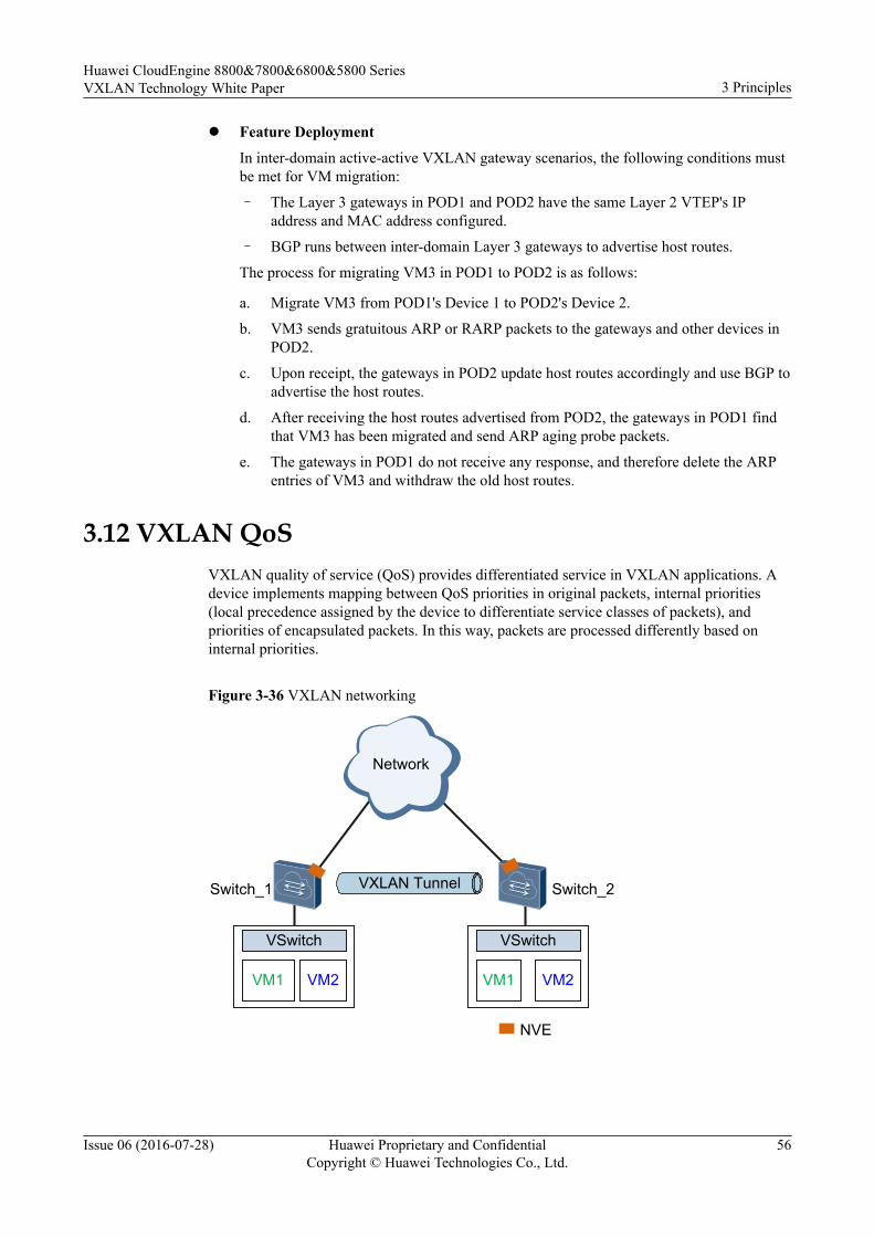
l Feature Deployment
In inter-domain active-active VXLAN gateway scenarios, the following conditions mustbe met for VM migration:
– The Layer 3 gateways in POD1 and POD2 have the same Layer 2 VTEP's IPaddress and MAC address configured.
– BGP runs between inter-domain Layer 3 gateways to advertise host routes.
The process for migrating VM3 in POD1 to POD2 is as follows:
a. Migrate VM3 from POD1's Device 1 to POD2's Device 2.
b. VM3 sends gratuitous ARP or RARP packets to the gateways and other devices inPOD2.
c. Upon receipt, the gateways in POD2 update host routes accordingly and use BGP toadvertise the host routes.
d. After receiving the host routes advertised from POD2, the gateways in POD1 findthat VM3 has been migrated and send ARP aging probe packets.
e. The gateways in POD1 do not receive any response, and therefore delete the ARPentries of VM3 and withdraw the old host routes.
3.12 VXLAN QoSVXLAN quality of service (QoS) provides differentiated service in VXLAN applications. Adevice implements mapping between QoS priorities in original packets, internal priorities(local precedence assigned by the device to differentiate service classes of packets), andpriorities of encapsulated packets. In this way, packets are processed differently based oninternal priorities.
Figure 3-36 VXLAN networking
Network
VM1 VM2
VSwitch
VM1 VM2
VSwitch
Switch_1 Switch_2VXLAN Tunnel
NVE
Huawei CloudEngine 8800&7800&6800&5800 SeriesVXLAN Technology White Paper 3 Principles
Issue 06 (2016-07-28) Huawei Proprietary and ConfidentialCopyright © Huawei Technologies Co., Ltd.
56
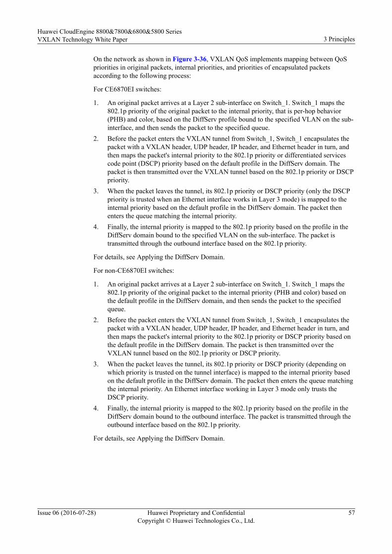
On the network as shown in Figure 3-36, VXLAN QoS implements mapping between QoSpriorities in original packets, internal priorities, and priorities of encapsulated packetsaccording to the following process:
For CE6870EI switches:
1. An original packet arrives at a Layer 2 sub-interface on Switch_1. Switch_1 maps the802.1p priority of the original packet to the internal priority, that is per-hop behavior(PHB) and color, based on the DiffServ profile bound to the specified VLAN on the sub-interface, and then sends the packet to the specified queue.
2. Before the packet enters the VXLAN tunnel from Switch_1, Switch_1 encapsulates thepacket with a VXLAN header, UDP header, IP header, and Ethernet header in turn, andthen maps the packet's internal priority to the 802.1p priority or differentiated servicescode point (DSCP) priority based on the default profile in the DiffServ domain. Thepacket is then transmitted over the VXLAN tunnel based on the 802.1p priority or DSCPpriority.
3. When the packet leaves the tunnel, its 802.1p priority or DSCP priority (only the DSCPpriority is trusted when an Ethernet interface works in Layer 3 mode) is mapped to theinternal priority based on the default profile in the DiffServ domain. The packet thenenters the queue matching the internal priority.
4. Finally, the internal priority is mapped to the 802.1p priority based on the profile in theDiffServ domain bound to the specified VLAN on the sub-interface. The packet istransmitted through the outbound interface based on the 802.1p priority.
For details, see Applying the DiffServ Domain.
For non-CE6870EI switches:
1. An original packet arrives at a Layer 2 sub-interface on Switch_1. Switch_1 maps the802.1p priority of the original packet to the internal priority (PHB and color) based onthe default profile in the DiffServ domain, and then sends the packet to the specifiedqueue.
2. Before the packet enters the VXLAN tunnel from Switch_1, Switch_1 encapsulates thepacket with a VXLAN header, UDP header, IP header, and Ethernet header in turn, andthen maps the packet's internal priority to the 802.1p priority or DSCP priority based onthe default profile in the DiffServ domain. The packet is then transmitted over theVXLAN tunnel based on the 802.1p priority or DSCP priority.
3. When the packet leaves the tunnel, its 802.1p priority or DSCP priority (depending onwhich priority is trusted on the tunnel interface) is mapped to the internal priority basedon the default profile in the DiffServ domain. The packet then enters the queue matchingthe internal priority. An Ethernet interface working in Layer 3 mode only trusts theDSCP priority.
4. Finally, the internal priority is mapped to the 802.1p priority based on the profile in theDiffServ domain bound to the outbound interface. The packet is transmitted through theoutbound interface based on the 802.1p priority.
For details, see Applying the DiffServ Domain.
Huawei CloudEngine 8800&7800&6800&5800 SeriesVXLAN Technology White Paper 3 Principles
Issue 06 (2016-07-28) Huawei Proprietary and ConfidentialCopyright © Huawei Technologies Co., Ltd.
57
4 Applications
About This Chapter
This section describes VXLAN applications.
4.1 Application for Communication Between Terminal Users on a VXLAN
4.2 Application for Communication Between Terminal Users on a VXLAN and LegacyNetwork
4.3 Application in VM Migration Scenarios
Huawei CloudEngine 8800&7800&6800&5800 SeriesVXLAN Technology White Paper 4 Applications
Issue 06 (2016-07-28) Huawei Proprietary and ConfidentialCopyright © Huawei Technologies Co., Ltd.
58
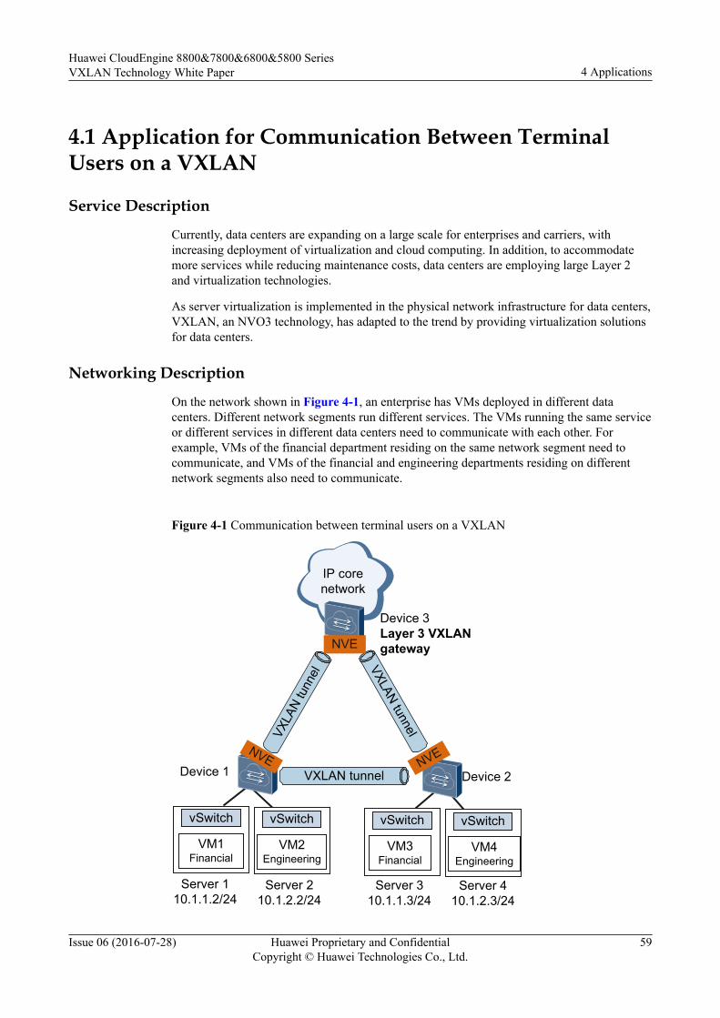
4.1 Application for Communication Between TerminalUsers on a VXLAN
Service Description
Currently, data centers are expanding on a large scale for enterprises and carriers, withincreasing deployment of virtualization and cloud computing. In addition, to accommodatemore services while reducing maintenance costs, data centers are employing large Layer 2and virtualization technologies.
As server virtualization is implemented in the physical network infrastructure for data centers,VXLAN, an NVO3 technology, has adapted to the trend by providing virtualization solutionsfor data centers.
Networking Description
On the network shown in Figure 4-1, an enterprise has VMs deployed in different datacenters. Different network segments run different services. The VMs running the same serviceor different services in different data centers need to communicate with each other. Forexample, VMs of the financial department residing on the same network segment need tocommunicate, and VMs of the financial and engineering departments residing on differentnetwork segments also need to communicate.
Figure 4-1 Communication between terminal users on a VXLAN
IP core network
Server 110.1.1.2/24
Device 1 Device 2
Device 3Layer 3 VXLAN gateway
VXLA
N tu
nnel
VXLAN tunnel
VM1Financial
vSwitch
VM2Engineering
vSwitch
VM3Financial
vSwitch
VM4Engineering
vSwitch
Server 210.1.2.2/24
Server 310.1.1.3/24
Server 410.1.2.3/24
VXLAN tunnel
NVE NVE
NVE
Huawei CloudEngine 8800&7800&6800&5800 SeriesVXLAN Technology White Paper 4 Applications
Issue 06 (2016-07-28) Huawei Proprietary and ConfidentialCopyright © Huawei Technologies Co., Ltd.
59
Feature DeploymentAs shown in Figure 4-1:l Deploy Device 1 and Device 2 as Layer 2 VXLAN gateways and establish a VXLAN
tunnel between Device 1 and Device 2 to allow communication between terminal userson the same network segment.
l Deploy Device 3 as a Layer 3 VXLAN gateway and establish a VXLAN tunnel betweenDevice 1 and Device 3 and between Device 2 and Device 3 to allow communicationbetween terminal users on different network segments.
Configure VXLAN on devices to trigger VXLAN tunnel establishment and dynamic learningof ARP and MAC address entries. By now, terminal users on the same network segment anddifferent network segments can communicate through the Layer 2 and Layer 3 VXLANgateways based on ARP and routing entries.
4.2 Application for Communication Between TerminalUsers on a VXLAN and Legacy Network
Service DescriptionCurrently, data centers are expanding on a large scale for enterprises and carriers, withincreasing deployment of virtualization and cloud computing. In addition, to accommodatemore services while reducing maintenance costs, data centers are employing large Layer 2and virtualization technologies.
As server virtualization is implemented in the physical network infrastructure for data centers,VXLAN, an NVO3 technology, has adapted to the trend by providing virtualization solutionsfor data centers, allowing intra-VXLAN communication and communication betweenVXLANs and legacy networks.
Networking DescriptionOn the network shown in Figure 4-2, an enterprise has VMs deployed for the finance andengineering departments and a legacy network for the human resource department. Thefinance and engineering departments need to communicate with the human resourcedepartment.
Huawei CloudEngine 8800&7800&6800&5800 SeriesVXLAN Technology White Paper 4 Applications
Issue 06 (2016-07-28) Huawei Proprietary and ConfidentialCopyright © Huawei Technologies Co., Ltd.
60
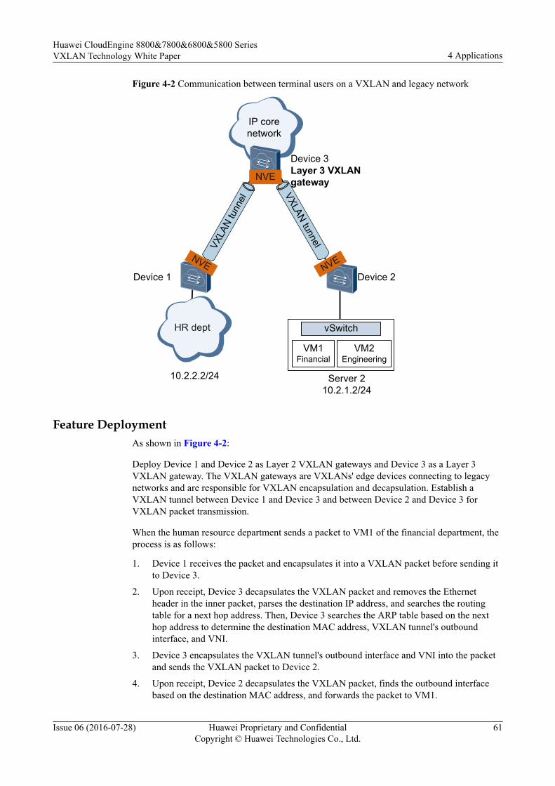
Figure 4-2 Communication between terminal users on a VXLAN and legacy network
IP corenetwork
Server 210.2.1.2/24
Device 1 Device 2
Device 3Layer 3 VXLAN gateway
VXLA
N tu
nnel
VXLAN tunnel
VM1Financial
VM2Engineering
vSwitch
10.2.2.2/24
HR dept
NVE NVE
NVE
Feature DeploymentAs shown in Figure 4-2:
Deploy Device 1 and Device 2 as Layer 2 VXLAN gateways and Device 3 as a Layer 3VXLAN gateway. The VXLAN gateways are VXLANs' edge devices connecting to legacynetworks and are responsible for VXLAN encapsulation and decapsulation. Establish aVXLAN tunnel between Device 1 and Device 3 and between Device 2 and Device 3 forVXLAN packet transmission.
When the human resource department sends a packet to VM1 of the financial department, theprocess is as follows:
1. Device 1 receives the packet and encapsulates it into a VXLAN packet before sending itto Device 3.
2. Upon receipt, Device 3 decapsulates the VXLAN packet and removes the Ethernetheader in the inner packet, parses the destination IP address, and searches the routingtable for a next hop address. Then, Device 3 searches the ARP table based on the nexthop address to determine the destination MAC address, VXLAN tunnel's outboundinterface, and VNI.
3. Device 3 encapsulates the VXLAN tunnel's outbound interface and VNI into the packetand sends the VXLAN packet to Device 2.
4. Upon receipt, Device 2 decapsulates the VXLAN packet, finds the outbound interfacebased on the destination MAC address, and forwards the packet to VM1.
Huawei CloudEngine 8800&7800&6800&5800 SeriesVXLAN Technology White Paper 4 Applications
Issue 06 (2016-07-28) Huawei Proprietary and ConfidentialCopyright © Huawei Technologies Co., Ltd.
61

4.3 Application in VM Migration Scenarios
Service DescriptionEnterprises on data center networks deploy server virtualization to implement IT resourceintegration, improve resource usage, and reduce network costs. With the wider deployment ofserver virtualization, more VMs are running in physical servers, and more applications arerunning in virtualization environments, which brings challenges to virtual networks.
Networking DescriptionOn the network shown in Figure 4-3, an enterprise has two clusters in the data center:engineering and financial departments in Server1 and the marketing department in Server2.
The computation space on Server1 is inadequate, whereas that on Server2 is not fully utilized.The network administrator wants to migrate the engineering department to Server2 withoutaffecting services.
Figure 4-3 Enterprise distribution networking
VM VM VM VM VM VM
Server1
VM
Server2
Engineering (VLAN10):10.1.1.1/24Finance (VLAN20):10.1.1.1/24Marketing (VLAN30):10.1.1.2/24
PG-Engineering PG-Finance PG-Marketing
VSwitch VSwitch
Device1 Device2
VXLAN Tunnel
Network
NV
E
NV
E
Feature DeploymentTo ensure that services are not interrupted during the migration of the engineering department,the IP and MAC addresses of the engineering department must remain unchanged. Thisrequires that the two Servers belong to the same Layer 2 network. Conventional methods
Huawei CloudEngine 8800&7800&6800&5800 SeriesVXLAN Technology White Paper 4 Applications
Issue 06 (2016-07-28) Huawei Proprietary and ConfidentialCopyright © Huawei Technologies Co., Ltd.
62

would require additional physical devices for traffic distribution and may also result innetwork loops and additional system and management costs.
VXLAN can be used to migrate the engineering department to Server 2. VXLAN is a networkvirtualization technique that uses MAC-in-UDP encapsulation. All terminal users who arereachable at Layer 3 can construct a large Layer 2 network as long as the physical networksupports IP forwarding.
The migration process for the engineering department is as follows:
1. Migrate the engineering department from Server 1 to Server 2.2. After migration, the VMs of the engineering department send gratuitous ARP or RARP
packets to notify Device 2 and other devices of the migration event.3. Device 1 receives the packets and replaces existing MAC address and ARP tables with
new MAC address and ARP tables of the post-migrated VMs.
VXLAN allows the engineering department to migrate, whereas the network is unaware of it.After the engineering department is migrated from Server 1 to Server 2, tenants sendgratuitous ARP or RARP packets. The MAC address and ARP tables of pre-migrated VMssaved on gateways are replaced by new MAC address and ARP tables of post-migrated VMs.
Huawei CloudEngine 8800&7800&6800&5800 SeriesVXLAN Technology White Paper 4 Applications
Issue 06 (2016-07-28) Huawei Proprietary and ConfidentialCopyright © Huawei Technologies Co., Ltd.
63
5 Configuration Notes
This section describes VXLAN configuration notes.
Involved Network ElementsYou can configure VXLAN on an AC controller or in a single-node mode. Different networkelements (NEs) are required for the three configuration modes. During the configuration,select a proper controller version.
Configuration Mode Product Description
AC controller mode Agile Controller Uses the NETCONFprotocol to control VXLANtunnel setup betweendevices and uses theOpenFlow protocol tocontrol packet forwardingover the tunnels.
Single-node mode No other NEs are required.
License SupportThe VXLAN function is controlled by a license and is disabled by default on theCE8800&7800&6800&5800 series switches. To use the VXLAN function, apply for andpurchase a license from the equipment supplier.
Huawei CloudEngine 8800&7800&6800&5800 SeriesVXLAN Technology White Paper 5 Configuration Notes
Issue 06 (2016-07-28) Huawei Proprietary and ConfidentialCopyright © Huawei Technologies Co., Ltd.
64
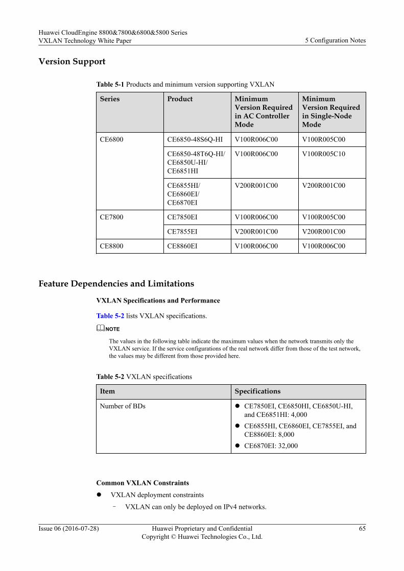
Version Support
Table 5-1 Products and minimum version supporting VXLAN
Series Product MinimumVersion Requiredin AC ControllerMode
MinimumVersion Requiredin Single-NodeMode
CE6800 CE6850-48S6Q-HI V100R006C00 V100R005C00
CE6850-48T6Q-HI/CE6850U-HI/CE6851HI
V100R006C00 V100R005C10
CE6855HI/CE6860EI/CE6870EI
V200R001C00 V200R001C00
CE7800 CE7850EI V100R006C00 V100R005C00
CE7855EI V200R001C00 V200R001C00
CE8800 CE8860EI V100R006C00 V100R006C00
Feature Dependencies and Limitations
VXLAN Specifications and Performance
Table 5-2 lists VXLAN specifications.
NOTE
The values in the following table indicate the maximum values when the network transmits only theVXLAN service. If the service configurations of the real network differ from those of the test network,the values may be different from those provided here.
Table 5-2 VXLAN specifications
Item Specifications
Number of BDs l CE7850EI, CE6850HI, CE6850U-HI,and CE6851HI: 4,000
l CE6855HI, CE6860EI, CE7855EI, andCE8860EI: 8,000
l CE6870EI: 32,000
Common VXLAN Constraints
l VXLAN deployment constraints
– VXLAN can only be deployed on IPv4 networks.
Huawei CloudEngine 8800&7800&6800&5800 SeriesVXLAN Technology White Paper 5 Configuration Notes
Issue 06 (2016-07-28) Huawei Proprietary and ConfidentialCopyright © Huawei Technologies Co., Ltd.
65

– In an earlier version than V200R001C00, STP cannot be configured on a user-sideinterface of a VXLAN tunnel. Starting from V200R001C00, STP can be configuredon a user-side interface of a VXLAN tunnel that accesses the VXLAN as a VLAN.
– It is recommended that the controller mode and single-node mode be not usedsimultaneously for networking. The controller mode applies on large-scalenetworks, and the single-node mode applies on small- and medium-scale networks.
– The device supports only head-end replication, but not multicast replication, forbroadcast, Unknown unicast, and multicast (BUM) packets.
– CE switches do not support fragmentation or reassembly of VXLAN packets. On aVXLAN network where both CE and non-CE devices are deployed, when packetsare fragmented on a non-CE device, the packets cannot be reassembled by a CEdevice. In this case, packet forwarding fails. To prevent this problem, you areadvised to set the maximum frame length to be at most 1400 bytes on the server.
– For CE6870EI switches, on the device at the VXLAN tunnel egress, all VXLANpackets cannot be redirected to interfaces.
– For non-CE6870EI switches, when outbound mirroring is performed forencapsulated VXLAN packets on the VXLAN-enabled device, the source MACaddress, destination MAC address, and VLAN ID encapsulated in the packetsreceived by the observing port are all 0s, but service data is correct.
– After all-active gateways are configured, you need to specify the non-gateway IPaddress as the source IP address for sending ICMP Echo Request packets whenpinging the host address from a gateway.
– In V100R005C10 and earlier versions, switches can connect to the VXLANnetwork through Layer 2 sub-interfaces only. Starting from V100R006C00,switches can also connect to the VXLAN network through VLANs.
– Distributed gateways do not support VXLAN network access through VLANs.– ARP broadcast suppression is not supported when VLANs are connected to the
VXLAN.– In versions earlier than V200R001C00, Eth-Trunk member interfaces cannot
forward packets from the specified VLANs to the VXLAN network.– In V100R005C00, after a Layer 2 sub-interface is added to a BD, you cannot create
a VBDIF interface for the BD.From V100R005C10, after a Layer 2 sub-interfaces with the flow encapsulationtype set to default is added to a BD, you cannot create a VBDIF interface for theBD.
– If NVE interfaces of Layer 2 and Layer 3 modes are configured on the devicesimultaneously, you must specify different source VTEP IP addresses for them.
– After centralized all-active VXLAN gateways are created, you are not advised todelete or shut down the VBDIF interfaces on all these gateways. Ensure that trafficis directed to another gateway based on proper route planning before you delete orshut down a VBDIF interface on a gateway. Otherwise, some traffic may be lost.
– For CE6855HI and CE7855EI switches in dual-active access or multi-activeVXLAN gateway scenarios, pay attention to the following:n A CE6855HI or CE7855EI switch can perform exact match on the MAC
addresses of a maximum of 500 VBDIF interfaces. The switch routes thepackets only when the destination MAC addresses in received IP packetsmatch the MAC addresses of the VBDIF interfaces.
n If more than 500 VBDIF interfaces have MAC addresses configured, theswitch performs fuzzy match on the MAC addresses. The switch routes the
Huawei CloudEngine 8800&7800&6800&5800 SeriesVXLAN Technology White Paper 5 Configuration Notes
Issue 06 (2016-07-28) Huawei Proprietary and ConfidentialCopyright © Huawei Technologies Co., Ltd.
66
packets so long as the destination MAC addresses in received IP packets matchthe MAC address of any VBDIF interface.
n When more than 500 VBDIF interfaces have MAC addresses configured, if thedevice connected to the switch runs Virtual Router Redundancy Protocol(VRRP), the virtual VRRP MAC address of the device cannot be the same asthe MAC address of any VBDIF interface on the switch.
– After distributed gateway is enabled on a Layer 3 gateway, the Layer 3 gatewaydiscards network-side ARP messages and learns only user-side ARP messages.
– In VXLAN dual-active access scenarios, when traffic enters the peer-link interface,the switch can map IP packets based on the DSCP priority only and map non-IPpackets based on the priority by the port priority command only.
– When one server is connected to two active access devices on the VXLAN network,you cannot run the encapsulation command to config the encapsulation type of theLayer 2 sub-interfaces configured on the dual-homed interfaces to default.
– Starting from V200R001C00, Layer 2 sub-interfaces where the encapsulation modeis QinQ can connect to the VXLAN network. When connecting these Layer 2 sub-interfaces to the VXLAN network, pay attention to the following restrictions:
n In a dual-active VXLAN access scenario, the encapsulation mode of a Layer 2sub-interface cannot be QinQ.
n A static MAC address cannot be configured for a Layer 2 sub-interface wherethe encapsulation mode is QinQ.
n When SVF is configured, the encapsulation mode of a Layer 2 sub-interfaceon the VXLAN cannot be QinQ. Similarly, if the encapsulation mode of aLayer 2 sub-interface on the VXLAN is QinQ, SVF cannot be configured.
n If a Layer 2 sub-interface where the encapsulation mode is QinQ is bound to aBD, the corresponding BDIF interface cannot be created for the BD. Similarly,if a BDIF interface is created for a BD, a Layer 2 sub-interface where theencapsulation mode is QinQ cannot be bound to the BD.
n If a Layer 2 sub-interface where the encapsulation mode is QinQ is bound to aBD, ARP broadcast suppression cannot be configured for the BD. Similarly, ifARP broadcast suppression is configured for a BD, a Layer 2 sub-interfacewhere the encapsulation mode is QinQ cannot be bound to the BD.
n If the port vlan-mapping command is configured on a main interface, a Layer2 sub-interface where the encapsulation mode is QinQ cannot be configured onthe main interface. Similarly, if a Layer 2 sub-interface where theencapsulation mode is QinQ is configured on a main interface, the port vlan-mapping command cannot be configured on the main interface.
n The rewrite pop double command must be configured for all or none Layer 2sub-interfaces where the encapsulation mode is QinQ in the same BD.
l Constraints on VXLAN traffic statistics collection
For non-CE6870EI switches:
– In the SVF set up by fixed switches, ports on leaf switch do not support BD-basedtraffic statistics collection.
– A CE6855HI or CE7855EI switch that functions as a decapsulation device on aVXLAN tunnel cannot collect BD-based traffic statistics on decapsulated ARPunicast packets. To query ARP packet statistics, run the display arp packetstatistics [ interface [ interface-type interface-number ] ] command.
Huawei CloudEngine 8800&7800&6800&5800 SeriesVXLAN Technology White Paper 5 Configuration Notes
Issue 06 (2016-07-28) Huawei Proprietary and ConfidentialCopyright © Huawei Technologies Co., Ltd.
67
– Traffic statistics collection for VPN instances is not supported on VBDIF interfaces.For CE6870EI switches:– In BD-based traffic statistics, the statistics in the outbound direction for packets
forwarded from the Ethernet to VXLAN network do not include the number ofbytes added during VXLAN encapsulation. The statistics in the inbound directionfor packets forwarded from the VXLAN to Ethernet network include the number ofbytes added during VXLAN encapsulation.
– BD-based traffic statistics in the outbound direction do not contain packetsforwarded at Layer 3.
– Traffic statistics collection for VPN instances is not supported on VBDIF interfaces.– Traffic statistics collection for VXLAN tunnel can only collect known unicast
traffic statistics in the outbound direction.– Among BD traffic statistics collection, MQC traffic statistics collection, and
VXLAN tunnel traffic statistics collection, the first has the highest priority and thelast has the lowest priority. If two or all of them are configured, only the one withthe highest priority takes effect.
– When the device collects packet statistics based on the VXLAN tunnel and VNI, itcan only collect statistics on packets forwarded at Layer 2 in the outbounddirection.
l Constraints between VXLAN and other featuresFor non-CE6870EI switches:– In V100R005C10 and earlier versions, SVF and VXLAN conflict and cannot be
configured together. Starting from V100R006C00, in centralized forwarding mode,the SVF system supports the VXLAN feature. Only the CE6850HI, CE6851HI,CE6850U-HI, CE6855HI, CE7850EI, or CE7855EI can function as a parent device,and a leaf device can only serve as the access-side device of the VXLAN tunnel.
– In the SVF system, VXLAN and TRILL services share chip resources. When youconfigure VXLAN or TRILL services, the switch will generate an alarm if chipresources are insufficient for the services, and the corresponding services for whichno chip resources are available will not take effect. In this case, you are advised todelete redundant VXLAN or TRILL services that are not in use, then configurerequired services again.
– If a VLAN is configured to transmit user-side traffic from the VXLAN network, theVLAN cannot transmit traffic from the TRILL network.
– The device does not support MPLS encapsulation after VXLAN encapsulation, orVXLAN decapsulation after MPLS decapsulation.
– After VXLAN is configured, Layer 3 sub-interfaces do not support Layer 3transparent transmission of VXLAN packets.
– In large ARP table mode, you can only specify the IP address of a loopbackinterface on the device as the source VTEP IP address of the NVE interface.
– In VXLAN active-active or all-active access scenarios, devices that have VXLANactive-active or all-active access configured cannot be upgraded using ISSU.
– sFlow cannot collect inner information about VXLAN packets.– When sFlow sampling is performed on the outbound interfaces of a switch that
performs VXLAN encapsulation, VXLAN packets cannot be sampled. When sFlowsampling is performed on the outbound interfaces of a switch (except CE6870EI)that performs VXLAN decapsulation, the packets before decapsulation are sampledand both the source and destination MAC addresses are 0.
Huawei CloudEngine 8800&7800&6800&5800 SeriesVXLAN Technology White Paper 5 Configuration Notes
Issue 06 (2016-07-28) Huawei Proprietary and ConfidentialCopyright © Huawei Technologies Co., Ltd.
68

– In an earlier version than V200R001C00, NetStream cannot collect innerinformation about VXLAN packets. Starting from V200R001C00, NetStream cancollect inner information about VXLAN packets.
– Port isolation does not take effect for packets that are encapsulated throughVXLAN tunnels.
– DHCP snooping can only be configured on a VXLAN network-side interface, andcannot be configured with DHCP relay simultaneously.
– The VLAN, VXLAN, carrier VLAN, main interface, and Eth-Trunk where cardinteroperability mode is set to enhanced share system resources. If system resourcesare insufficient, the configuration may fail.
– If the bpdu bridge enable command is configured on an access-side interface ofthe VXLAN network connected to an STP network, BPDU packets cannot traversethe VXLAN network, causing loops on the STP network. To prevent loops, run theundo mac-address bpdu [ mac-address [ mac-address-mask ] ] command in thesystem view, where mac-address specifies the MAC addresses of BPDU packetsthat need to traverse the VXLAN network.
For CE6870EI switches:
– VXLAN cannot be configured simultaneously with GRE, TRILL, FCoE, MPLS,and multicast VPN. You can configure TRILL or FCoE after the VXLANconfiguration is deleted. However, the modification takes effect only after thedevice restarts.
– A QoS group where member interfaces are VLANs or VLANIF interfaces cannotbe used with ARP broadcast packet suppression on a VXLAN network.
– The device does not support MPLS encapsulation after VXLAN encapsulation, orVXLAN decapsulation after MPLS decapsulation.
– In VXLAN active-active or all-active access scenarios, devices that have VXLANactive-active or all-active access configured cannot be upgraded using ISSU.
– sFlow cannot collect inner information about VXLAN packets.
– In versions earlier than V200R001C00, port isolation does not take effect forpackets that are encapsulated through VXLAN tunnels. In V200R001C00 and laterversions, port isolation takes effect only for Layer 2 packets that are encapsulated atthe VXLAN service access side.
– Port security and DHCP snooping do not take effect on interfaces connected to theVXLAN.
– DHCP snooping can only be configured on a VXLAN network-side interface, andcannot be configured with DHCP relay simultaneously.
– You can run the assign forward nvo3 acl extend enable command to enable theNVO3 ACL extension function and restart the switch to reduce the failure toconfigure ACL-consuming services.
– The VLAN, VXLAN, carrier VLAN, main interface, and Eth-Trunk where cardinteroperability mode is set to enhanced share system resources. If system resourcesare insufficient, the configuration may fail.
Specific Constraints in AC Controller Mode
l When VMs are online, do not run commands on the device to modify configurationsdelivered by the AC controller; otherwise, the VXLAN service cannot run properly. Forexample, do not run commands to delete the BD, cancel the mapping between the VNI
Huawei CloudEngine 8800&7800&6800&5800 SeriesVXLAN Technology White Paper 5 Configuration Notes
Issue 06 (2016-07-28) Huawei Proprietary and ConfidentialCopyright © Huawei Technologies Co., Ltd.
69
and BD, modify the VTEP IP address, delete the VBDIF interface of a Layer 3 gateway,or modify the IP address of the VBDIF interface when VMs are online.
Huawei CloudEngine 8800&7800&6800&5800 SeriesVXLAN Technology White Paper 5 Configuration Notes
Issue 06 (2016-07-28) Huawei Proprietary and ConfidentialCopyright © Huawei Technologies Co., Ltd.
70
6 Configuring VXLAN (Through the Agile
Controller-DCN)
This section describes how to configure VXLAN using the Agile Controller-DCN.
Prerequisites
Before configuring VXLAN through the Agile Controller-DCN, complete the following tasks:
l Ensuring reachable routes between the devices
l Configure the devices to communicate with the Agile Controller-DCN through SNMPand NETCONF. For details, see SNMP Configuration and NETCONF Configuration.
l Running the ip tunnel mode vxlan command on the device to set the tunnel mode toVXLAN. (Perform this step on the CE6870EI only.)
l Running the assign forward nvo3 acl extend enable command on the device to enablethe NVO3 ACL extension function. (Perform this step on the CE6870EI only.)
Context
After NETCONF is configured on a device, the Agile Controller-DCN (NETCONF Manager)can use the NETCONF protocol to manage the device (NETCONF Agent). Other VXLAN-related configuration and entries except those described in this section are delivered to thedevice through the Agile Controller-DCN. For details about the Agile Controller-DCNconfiguration, see corresponding documents.
NOTICEWhen VMs are online, do not run commands on the device to modify configurationsdelivered by the Agile Controller-DCN; otherwise, the VXLAN service cannot run properly.For example, do not run commands to delete the BD, cancel the mapping between the VNIand BD, modify the VTEP IP address, delete the VBDIF interface of a Layer 3 gateway, ormodify the IP address of the VBDIF interface when VMs are online.
Huawei CloudEngine 8800&7800&6800&5800 SeriesVXLAN Technology White Paper
6 Configuring VXLAN (Through the Agile Controller-DCN)
Issue 06 (2016-07-28) Huawei Proprietary and ConfidentialCopyright © Huawei Technologies Co., Ltd.
71
Procedurel Table 6-1 lists the functions that can only be configured on the switch but cannot be
delivered by the Agile Controller-DCN.
Table 6-1 Functions that can only be configured on the switch but cannot be delivered bythe Agile Controller-DCN
Function DeploymentPosition
Configuration Procedure Remarks
(Optional)Configure all-activegateways forthe VXLANnetwork.
Centralizedall-activeVXLANgateway
1. Run the system-view commandto enter the system view.
2. Run the dfs-group dfs-group-idcommand to create a DFSgroup and enter the DFS groupview.By default, no DFS group iscreated.
3. Run the source ip ip-addresscommand to bind an IPv4address to the DFS group.By default, no IPv4 address isbound to the DFS group.
4. (Optional) Run the udp portport-number command tospecify a UDP port number forthe DFS group.By default, the UDP portnumber of the DFS group is61467.
5. Run the active-active-gatewaycommand to create all-activegateways and enter the all-active gateway view.By default, no all-activegateway is created.
6. Run the peer ip-address [ vpn-instance vpn-instance-name ]command to configure the IPaddress of an all-active gatewaypeer.By default, no all-activegateway peer is configured.
7. Run the commit command tocommit the configuration.
This step isrequiredwhen youwant todeploycentralizedall-activeVXLANgateways forthe network.Whenconfiguringcentralizedall-activeVXLANgateways,ensure thatthe VTEPsource IPaddress,ingressreplicationlist, and IPaddress andMACaddress ofthe VBDIFinterface arethe same onall the all-activegateways.
Huawei CloudEngine 8800&7800&6800&5800 SeriesVXLAN Technology White Paper
6 Configuring VXLAN (Through the Agile Controller-DCN)
Issue 06 (2016-07-28) Huawei Proprietary and ConfidentialCopyright © Huawei Technologies Co., Ltd.
72
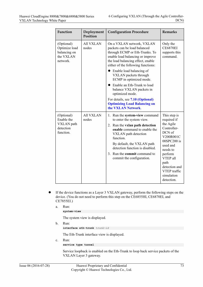
Function DeploymentPosition
Configuration Procedure Remarks
(Optional)Optimize loadbalancing onthe VXLANnetwork.
All VXLANnodes
On a VXLAN network, VXLANpackets can be load balancedthrough ECMP or Eth-Trunks. Toenable load balancing or improvethe load balancing effect, enableeither of the following functions:l Enable load balancing of
VXLAN packets throughECMP in optimized mode.
l Enable an Eth-Trunk to loadbalance VXLAN packets inoptimized mode.
For details, see 7.10 (Optional)Optimizing Load Balancing onthe VXLAN Network.
Only theCE6870EIsupports thiscommand.
(Optional)Enable theVXLAN pathdetectionfunction.
All VXLANnodes
1. Run the system-view commandto enter the system view.
2. Run the vxlan path detectionenable command to enable theVXLAN path detectionfunction.By default, the VXLAN pathdetection function is disabled.
3. Run the commit command tocommit the configuration.
This step isrequired ifthe AgileController-DCN ofV200R001C00SPC200 isused andneeds toperformVTEP allpathdetection andVTEP trafficsimulationdetection.
l If the device functions as a Layer 3 VXLAN gateway, perform the following steps on the
device. (You do not need to perform this step on the CE6855HI, CE6870EI, andCE7855EI.)a. Run:
system-view
The system view is displayed.b. Run:
interface eth-trunk trunk-id
The Eth-Trunk interface view is displayed.c. Run:
service type tunnel
Service loopback is enabled on the Eth-Trunk to loop back service packets of theVXLAN Layer 3 gateway.
Huawei CloudEngine 8800&7800&6800&5800 SeriesVXLAN Technology White Paper
6 Configuring VXLAN (Through the Agile Controller-DCN)
Issue 06 (2016-07-28) Huawei Proprietary and ConfidentialCopyright © Huawei Technologies Co., Ltd.
73
NOTE
l One service loopback interface takes effect for a maximum of 2000 VBDIF interfaces.
l After you run the service type tunnel command on an Eth-Trunk, the Eth-Trunk and itsphysical member interfaces can only be used for the VXLAN Layer 3 gateway andcannot be configured with other services.
d. Run:trunkport interface-type { interface-number1 [ to interface-number2 ] } &<1-16>
Member interfaces are added to the Eth-Trunk.
NOTE
l The member interfaces must be idle and do not transmit services.
l Ensure that the Eth-Trunk bandwidth is at least twice the bandwidth required fortransmitting VXLAN Layer 3 gateway traffic. For example, if traffic is sent from usersto the gateway across the VXLAN network at a rate of 10 Gbit/s, add two 10GEinterface to the Eth-Trunk that you want to use as the service loopback interface.
e. Run:quit
Return to the system view.
----End
Huawei CloudEngine 8800&7800&6800&5800 SeriesVXLAN Technology White Paper
6 Configuring VXLAN (Through the Agile Controller-DCN)
Issue 06 (2016-07-28) Huawei Proprietary and ConfidentialCopyright © Huawei Technologies Co., Ltd.
74

7 Configuring VXLAN in Single-Node,
Centralized Gateway, and Static Mode
About This Chapter
When VXLAN in centralized gateway mode for static tunnel establishment is deployed,traffic across network segments is forwarded through Layer 3 VXLAN gateways toimplement centralized traffic management.
Usage ScenarioAn enterprise has allocated VMs in different locations to a tenant. Some of the VMs reside onthe same network segment, and the others reside on different network segments. To allowcommunication between VMs, deploy Layer 2 and Layer 3 VXLAN gateways and establishVXLAN tunnels.
On the network shown in Figure 7-1, Server 2 and Server 3 belong to the same networksegment and access the VXLAN through Device 1 and Device 2, respectively; Server 1 andServer 2 belong to different network segments and both access the VXLAN through Device 1.l To allow VM 1 on Server 2 and VM 1 on Server 3 to communicate, deploy Layer 2
VXLAN gateways on Device 1 and Device 2 and establish a VXLAN tunnel betweenDevice 1 and Device 2 so that tenants on the same network segment can communicate.
l To allow VM 1 on Server 1 and VM 1 on Server 3 to communicate, deploy a Layer 3VXLAN gateway on Device 3 and establish a VXLAN tunnel between Device 1 andDevice 3 and between Device 2 and Device 3 so that tenants on different networksegments can communicate.
Huawei CloudEngine 8800&7800&6800&5800 SeriesVXLAN Technology White Paper
7 Configuring VXLAN in Single-Node, CentralizedGateway, and Static Mode
Issue 06 (2016-07-28) Huawei Proprietary and ConfidentialCopyright © Huawei Technologies Co., Ltd.
75
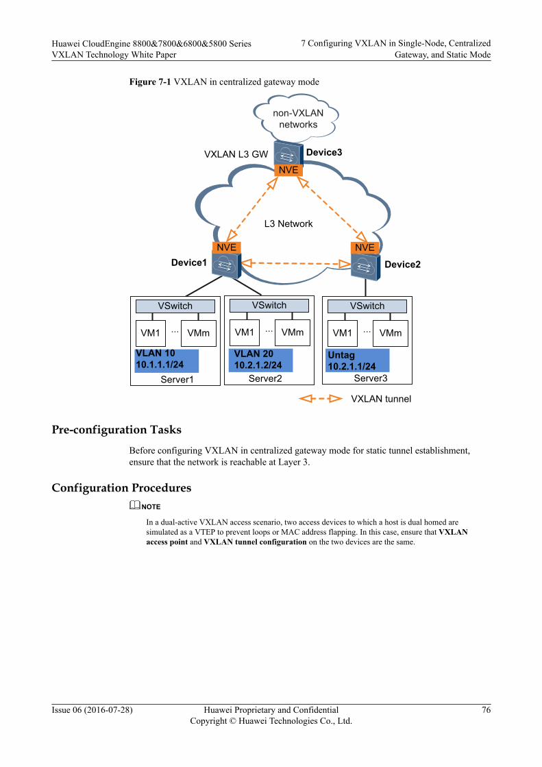
Figure 7-1 VXLAN in centralized gateway mode
VM1 VMm
VSwitch
...
Device1
Server1
L3 Network
Device2
VM1 VMm
VSwitch
...
Server3
VLAN 1010.1.1.1/24
Untag10.2.1.1/24
VXLAN L3 GW
VXLAN tunnel
non-VXLAN networks
VM1 VMm
VSwitch
...
Server2
VLAN 2010.2.1.2/24
Device3
NVE
NVENVE
Pre-configuration TasksBefore configuring VXLAN in centralized gateway mode for static tunnel establishment,ensure that the network is reachable at Layer 3.
Configuration ProceduresNOTE
In a dual-active VXLAN access scenario, two access devices to which a host is dual homed aresimulated as a VTEP to prevent loops or MAC address flapping. In this case, ensure that VXLANaccess point and VXLAN tunnel configuration on the two devices are the same.
Huawei CloudEngine 8800&7800&6800&5800 SeriesVXLAN Technology White Paper
7 Configuring VXLAN in Single-Node, CentralizedGateway, and Static Mode
Issue 06 (2016-07-28) Huawei Proprietary and ConfidentialCopyright © Huawei Technologies Co., Ltd.
76

Figure 7-2 Flowchart for configuring intra-segment communication through centralizedVXLAN gateways
Configure a VXLAN tunnel.
Mandatory
Optional
Configure static MAC address entries and MAC address
limiting.
Configure a service access point.
Configure MAC address flapping detection and a
VXLAN BD whitelist.
NOTETo implement intra-segment communication through centralized VXLAN gateways, configure onlystatic MAC address entries and MAC address limiting described in 7.8 (Optional) Configuring StaticARP/MAC Address Entries and MAC Address Limiting.
Huawei CloudEngine 8800&7800&6800&5800 SeriesVXLAN Technology White Paper
7 Configuring VXLAN in Single-Node, CentralizedGateway, and Static Mode
Issue 06 (2016-07-28) Huawei Proprietary and ConfidentialCopyright © Huawei Technologies Co., Ltd.
77
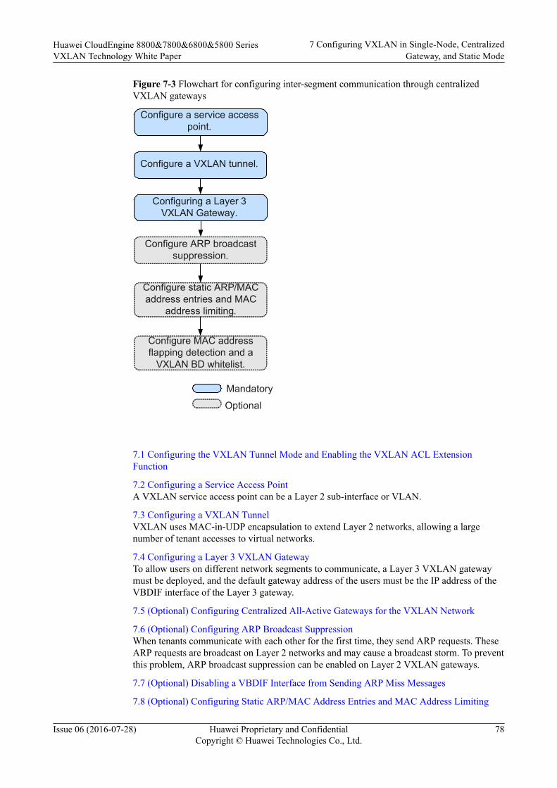
Figure 7-3 Flowchart for configuring inter-segment communication through centralizedVXLAN gateways
Configure a VXLAN tunnel.
Configure ARP broadcast suppression.
Mandatory
Optional
Configure static ARP/MAC address entries and MAC
address limiting.
Configure a service access point.
Configuring a Layer 3 VXLAN Gateway.
Configure MAC address flapping detection and a
VXLAN BD whitelist.
7.1 Configuring the VXLAN Tunnel Mode and Enabling the VXLAN ACL ExtensionFunction
7.2 Configuring a Service Access PointA VXLAN service access point can be a Layer 2 sub-interface or VLAN.
7.3 Configuring a VXLAN TunnelVXLAN uses MAC-in-UDP encapsulation to extend Layer 2 networks, allowing a largenumber of tenant accesses to virtual networks.
7.4 Configuring a Layer 3 VXLAN GatewayTo allow users on different network segments to communicate, a Layer 3 VXLAN gatewaymust be deployed, and the default gateway address of the users must be the IP address of theVBDIF interface of the Layer 3 gateway.
7.5 (Optional) Configuring Centralized All-Active Gateways for the VXLAN Network
7.6 (Optional) Configuring ARP Broadcast SuppressionWhen tenants communicate with each other for the first time, they send ARP requests. TheseARP requests are broadcast on Layer 2 networks and may cause a broadcast storm. To preventthis problem, ARP broadcast suppression can be enabled on Layer 2 VXLAN gateways.
7.7 (Optional) Disabling a VBDIF Interface from Sending ARP Miss Messages
7.8 (Optional) Configuring Static ARP/MAC Address Entries and MAC Address Limiting
Huawei CloudEngine 8800&7800&6800&5800 SeriesVXLAN Technology White Paper
7 Configuring VXLAN in Single-Node, CentralizedGateway, and Static Mode
Issue 06 (2016-07-28) Huawei Proprietary and ConfidentialCopyright © Huawei Technologies Co., Ltd.
78
Static ARP entries or MAC address entries can be configured for traffic forwarding, andMAC address limiting can be configured to improve VXLAN security.
7.9 (Optional) Configuring a VXLAN BD Whitelist for MAC Address Flapping DetectionIn specific VXLAN applications, when a device connects to a load balancing server equippedwith two network interface cards, the server's MAC address may be learned by two interfaceson the device. This is a normal situation where MAC address flapping detection is not needed.In this case, configure a VXLAN BD whitelist for MAC address flapping detection.
7.10 (Optional) Optimizing Load Balancing on the VXLAN Network
7.11 Checking the ConfigurationsAfter configuring VXLAN in centralized gateway mode for static tunnel establishment, checkVXLAN tunnel, VNI, and VBDIF interface information.
Huawei CloudEngine 8800&7800&6800&5800 SeriesVXLAN Technology White Paper
7 Configuring VXLAN in Single-Node, CentralizedGateway, and Static Mode
Issue 06 (2016-07-28) Huawei Proprietary and ConfidentialCopyright © Huawei Technologies Co., Ltd.
79
7.1 Configuring the VXLAN Tunnel Mode and Enablingthe VXLAN ACL Extension Function
Contextl Configuring a tunnel mode: You need to set the tunnel mode to VXLAN when
configuring the VXLAN feature; otherwise, the configurations do not take effect.l Enabling the VXLAN ACL extension function: By default, the VXLAN ACL extension
function is disabled on the device. If you configure other ACL resource-consumingservices, such as MQC, simplified ACL, traffic policing, and BD traffic statisticscollection, on the device deployed with VXLAN services, there is high probability thatthe other services fail to be configured. You can enable the VXLAN ACL extensionfunction to lower the configuration failure probability.
To ensure normal forwarding of VXLAN packets, the VXLAN tunnel mode must have beenconfigured and the VXLAN ACL extension function must have been enabled on Layer 2 andLayer 3 VXLAN gateways.
NOTE
You can configure the VXLAN tunnel mode and enable the VXLAN ACL extension function only onthe CE6870EI.
Procedure
Step 1 Run:system-view
The system view is displayed.
Step 2 Run:ip tunnel mode vxlan
The tunnel mode is set to VXLAN.
By default, the tunnel mode is VXLAN.
Step 3 Run:assign forward nvo3 acl extend enable
The VXLAN ACL extension function is enabled.
By default, the VXLAN ACL extension function is disabled.
Step 4 Run:commit
The configuration is committed.
----End
Follow-up ProcedureAfter configuring the VXLAN tunnel mode and enabling the VXLAN ACL extensionfunction, you need to save the configuration and restart the switch to make the configurationtake effect.
Huawei CloudEngine 8800&7800&6800&5800 SeriesVXLAN Technology White Paper
7 Configuring VXLAN in Single-Node, CentralizedGateway, and Static Mode
Issue 06 (2016-07-28) Huawei Proprietary and ConfidentialCopyright © Huawei Technologies Co., Ltd.
80

7.2 Configuring a Service Access PointA VXLAN service access point can be a Layer 2 sub-interface or VLAN.
ContextWhen a Layer 2 sub-interface is used as a service access point, different encapsulation typescan be configured for the sub-interface to transmit various types of data packets. After a Layer2 sub-interface is added to a BD, the sub-interface can transmit data packets through this BD.Table 7-1 describes the different encapsulation types.
Table 7-1 Traffic encapsulation types
TrafficEncapsulationType
Description
dot1q If a Dot1q sub-interface receives a single-tagged VLAN packet, thesub-interface forwards only the packet with a specifie VLAN ID. If aDot1q sub-interface receives a double-tagged VLAN packet, the sub-interface forwards only the packet with a specified outer VLAN ID.l When performing VXLAN encapsulation on packets, a Dot1q
Layer 2 sub-interface removes the outer tags of the packets.l When performing VXLAN decapsulation on packets, a Dot1q
Layer 2 sub-interface replaces the VLAN tags with specifiedVLAN tags if the inner packets carry VLAN tags, or addsspecified VLAN tags to the packets if the inner packets do notcarry VXLAN tags.
When setting the encapsulation type to dot1q for a Layer 2 sub-interface, note the following:l The VLAN IDs specified for the Layer 2 sub-interface cannot be
the same as either the VLAN IDs of packets allowed to passthrough the corresponding Layer 2 interfaces or the MUX VLANIDs.
l Layer 2 and Layer 3 sub-interfaces cannot have the same VLANIDs specified.
Huawei CloudEngine 8800&7800&6800&5800 SeriesVXLAN Technology White Paper
7 Configuring VXLAN in Single-Node, CentralizedGateway, and Static Mode
Issue 06 (2016-07-28) Huawei Proprietary and ConfidentialCopyright © Huawei Technologies Co., Ltd.
81

TrafficEncapsulationType
Description
untag An untagged Layer 2 sub-interface receives only packets that do notcarry VLAN tags.l When performing VXLAN encapsulation on packets, an untagged
Layer 2 sub-interface does not add any VLAN tag to the packets.l When performing VXLAN decapsulation on packets, an untagged
Layer 2 sub-interface removes the VLAN tags of single-taggedinner packets or the outer VLAN tags of double-tagged innerpackets.
When setting the encapsulation type to untag for a Layer 2 sub-interface, note the following:l Ensure that the corresponding physical interface of the sub-
interface does not have any configuration, and is removed fromthe default VLAN.
l Untagged Layer 2 sub-interfaces can be configured only for Layer2 physical interfaces and Eth-Trunk interfaces.
l An interface can have only one untagged Layer 2 sub-interfaceconfigured.
qinq A QinQ sub-interface receives only tagged packets with specifiedinner and outer VLAN tags.l When performing VXLAN encapsulation on packets, a QinQ sub-
interface removes two VLAN tags from packets if the action ofthe Layer 2 sub-interface is set to removing two VLAN tags andmaintains the VLAN tags of packets if the action of the Layer 2sub-interface is not set to removing two VLAN tags.
l When performing VXLAN decapsulation on packets, a QinQ sub-interface adds two specific VLAN tags to packets if the action ofthe Layer 2 sub-interface is set to removing two VLAN tags andmaintain the VLAN tags of packets if the action of the Layer 2sub-interface is not set to removing two VLAN tags.
NOTEThe traffic behavior for QinQ interfaces bound to the same BD must be thesame.
QinQ interfaces do not support DHCP Snooping or VBDIF and cannot bebound to the same BD as Dot1q sub-interfaces. A QinQ interface can haveonly one outer VLAN tag and one inner VLAN tag.
Huawei CloudEngine 8800&7800&6800&5800 SeriesVXLAN Technology White Paper
7 Configuring VXLAN in Single-Node, CentralizedGateway, and Static Mode
Issue 06 (2016-07-28) Huawei Proprietary and ConfidentialCopyright © Huawei Technologies Co., Ltd.
82
TrafficEncapsulationType
Description
default A default Layer 2 sub-interface receives all packets, irrespective ofwhether the packets carry VLAN tags.When performing VXLAN encapsulation and decapsulation onpackets, a default Layer 2 sub-interface does not process VLAN tagsof the packets.When setting the encapsulation type to default for a Layer 2 sub-interface, note the following:l Ensure that the interface for the Layer 2 sub-interface is not added
to any VLAN.l Default Layer 2 sub-interfaces can be configured only for Layer 2
physical interfaces and Eth-Trunk interfaces.l If a default Layer 2 sub-interface is created for an interface, the
interface cannot have other types of Layer 2 sub-interfacesconfigured.
NOTEWhen a sub-interface that is configured with dot1q and QinQ receives double-tagged VLAN packets, theQinQ sub-interface preferentially processes the packets. For example, if a dot1q and QinQ sub-interfacecarries the VLAN ID of 10 for dot1q and outer VLAN ID of 10 and inner VLAN ID of 20 for QinQ andreceives a packet with the outer VLAN ID of 10 and inner VLAN ID of 20, the QinQ sub-interfacepreferentially processes the packet. If a dot1q and QinQ sub-interface carries the VLAN ID of 10 fordot1q and outer VLAN ID of 10 and inner VLAN ID of 20 for QinQ and receives a packet with theouter VLAN ID of 10 and inner VLAN ID of non-20, the dot1q sub-interface preferentially processesthe packet.
If a VLAN is used as a service access point, it can be bound to a BD for data packets in theVLAN to be transmitted through this BD.
Configure a service access point on a Layer 2 gateway.
Procedure
Step 1 Run:system-view
The system view is displayed.
Step 2 Run:bridge-domain bd-id
A BD is created, and the BD view is displayed.
By default, no BD is created.
Step 3 (Optional) Run:description description
A description is configured for the BD.
By default, no description is configured for a BD.
Huawei CloudEngine 8800&7800&6800&5800 SeriesVXLAN Technology White Paper
7 Configuring VXLAN in Single-Node, CentralizedGateway, and Static Mode
Issue 06 (2016-07-28) Huawei Proprietary and ConfidentialCopyright © Huawei Technologies Co., Ltd.
83
Step 4 Run:quit
Return to the system view.
Step 5 (Optional) Set the port mode to VXLAN access. (You do not need to perform this step on theCE6870EI.)
1. Run:interface interface-type interface-number
The interface view is displayed.2. Run:
port nvo3 mode access
The port mode is set to VXLAN access, so that the port can send common IP packetswith the destination UDP port number of VXLAN packets (defaults to 4789) to theVXLAN.By default, the port mode is not set to VXLAN access, that is, the port cannot sendcommon IP packets with the destination UDP port number of VXLAN packets (defaultsto 4789) to the VXLAN.
3. Run:quit
Return to the system view.
Step 6 Configure a service access point.l Configure a VLAN as a service access point.
NOTE
– In a distributed gateway scenario, a VLAN cannot be configured as a VXLAN service accesspoint.
– You cannot bind a VLAN to a BD while configuring the ARP broadcast suppression function.After a VLAN is configured as a VXLAN service access point, do not configure ARPbroadcast suppression.
– After a VLAN is bound to a BD, the BD becomes the broadcast domain. Therefore, otherservice configurations such as DHCP Snooping and IGMP Snooping in the VLAN becomeinvalid.
– VLAN and BD use 1:1 mapping. That is, a VLAN can be bound to only one BD, and only oneVLAN can be bound to a BD.
a. Run:bridge-domain bd-id
The view of an existing BD is displayed.b. Run:
l2 binding vlan vlan-id
A global VLAN is bound to the BD.By default, VLANs are not bound to any BD.
NOTE
Before performing this step, ensure that a global VLAN has been created. After binding theglobal VLAN to the BD, add the related device interfaces to the VLAN.
c. Run:commit
The configuration is committed.
Huawei CloudEngine 8800&7800&6800&5800 SeriesVXLAN Technology White Paper
7 Configuring VXLAN in Single-Node, CentralizedGateway, and Static Mode
Issue 06 (2016-07-28) Huawei Proprietary and ConfidentialCopyright © Huawei Technologies Co., Ltd.
84
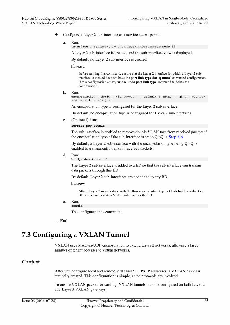
l Configure a Layer 2 sub-interface as a service access point.
a. Run:interface interface-type interface-number.subnum mode l2
A Layer 2 sub-interface is created, and the sub-interface view is displayed.By default, no Layer 2 sub-interface is created.
NOTE
Before running this command, ensure that the Layer 2 interface for which a Layer 2 sub-interface is created does not have the port link-type dot1q-tunnel command configuration.If this configuration exists, run the undo port link-type command to delete theconfiguration.
b. Run:encapsulation { dot1q [ vid ce-vid ] | default | untag | qinq [ vid pe-vid ce-vid ce-vid ] }
An encapsulation type is configured for the Layer 2 sub-interface.By default, no encapsulation type is configured for Layer 2 sub-interfaces.
c. (Optional) Run:rewrite pop double
The sub-interface is enabled to remove double VLAN tags from received packets ifthe encapsulation type of the sub-interface is set to QinQ in Step 6.b.By default, a Layer 2 sub-interface with the encapsulation type being QinQ isenabled to transparently transmit received packets.
d. Run:bridge-domain bd-id
The Layer 2 sub-interface is added to a BD so that the sub-interface can transmitdata packets through this BD.By default, Layer 2 sub-interfaces are not added to any BD.
NOTE
After a Layer 2 sub-interface with the flow encapsulation type set to default is added to aBD, you cannot create a VBDIF interface for the BD.
e. Run:commit
The configuration is committed.
----End
7.3 Configuring a VXLAN TunnelVXLAN uses MAC-in-UDP encapsulation to extend Layer 2 networks, allowing a largenumber of tenant accesses to virtual networks.
Context
After you configure local and remote VNIs and VTEP's IP addresses, a VXLAN tunnel isstatically created. This configuration is simple, as no protocols are involved.
To ensure VXLAN packet forwarding, VXLAN tunnels must be configured on both Layer 2and Layer 3 VXLAN gateways.
Huawei CloudEngine 8800&7800&6800&5800 SeriesVXLAN Technology White Paper
7 Configuring VXLAN in Single-Node, CentralizedGateway, and Static Mode
Issue 06 (2016-07-28) Huawei Proprietary and ConfidentialCopyright © Huawei Technologies Co., Ltd.
85
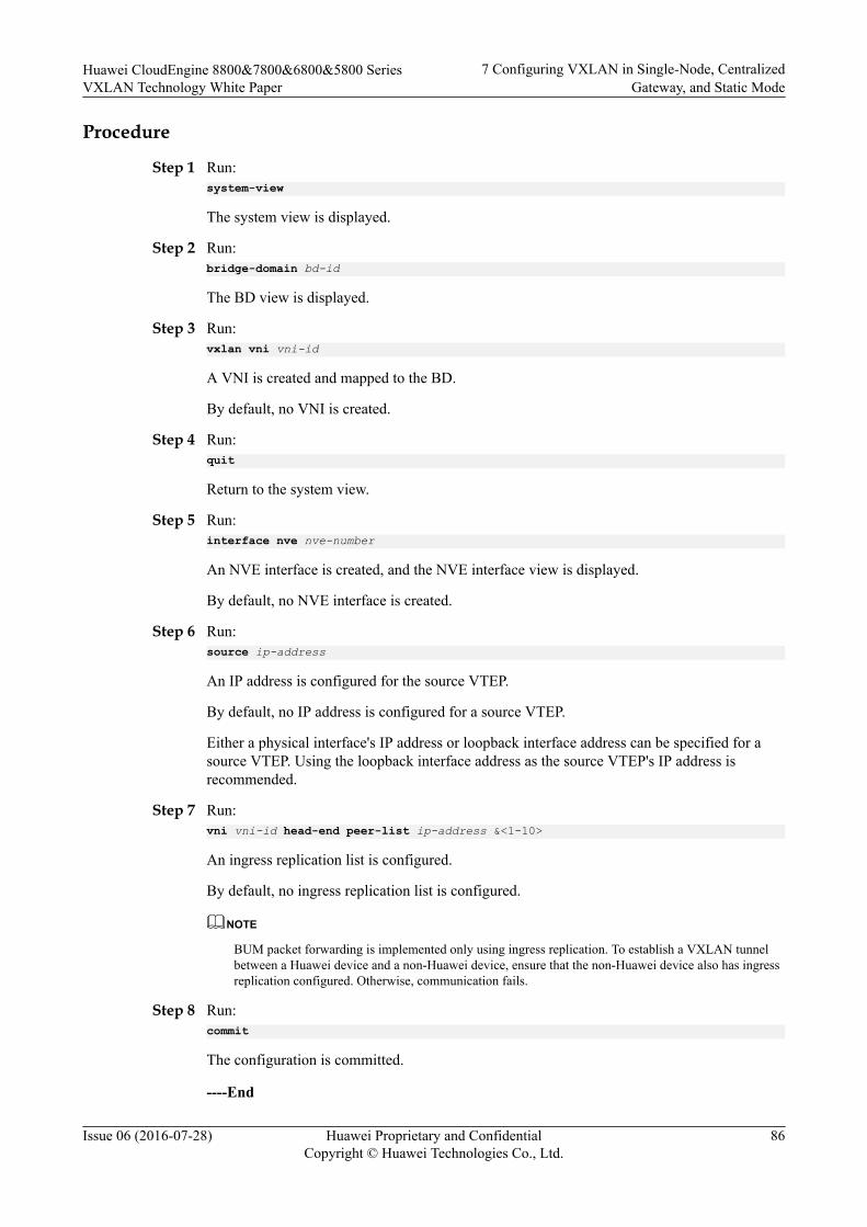
Procedure
Step 1 Run:system-view
The system view is displayed.
Step 2 Run:bridge-domain bd-id
The BD view is displayed.
Step 3 Run:vxlan vni vni-id
A VNI is created and mapped to the BD.
By default, no VNI is created.
Step 4 Run:quit
Return to the system view.
Step 5 Run:interface nve nve-number
An NVE interface is created, and the NVE interface view is displayed.
By default, no NVE interface is created.
Step 6 Run:source ip-address
An IP address is configured for the source VTEP.
By default, no IP address is configured for a source VTEP.
Either a physical interface's IP address or loopback interface address can be specified for asource VTEP. Using the loopback interface address as the source VTEP's IP address isrecommended.
Step 7 Run:vni vni-id head-end peer-list ip-address &<1-10>
An ingress replication list is configured.
By default, no ingress replication list is configured.
NOTE
BUM packet forwarding is implemented only using ingress replication. To establish a VXLAN tunnelbetween a Huawei device and a non-Huawei device, ensure that the non-Huawei device also has ingressreplication configured. Otherwise, communication fails.
Step 8 Run:commit
The configuration is committed.
----End
Huawei CloudEngine 8800&7800&6800&5800 SeriesVXLAN Technology White Paper
7 Configuring VXLAN in Single-Node, CentralizedGateway, and Static Mode
Issue 06 (2016-07-28) Huawei Proprietary and ConfidentialCopyright © Huawei Technologies Co., Ltd.
86

7.4 Configuring a Layer 3 VXLAN GatewayTo allow users on different network segments to communicate, a Layer 3 VXLAN gatewaymust be deployed, and the default gateway address of the users must be the IP address of theVBDIF interface of the Layer 3 gateway.
Context
A tenant is identified by a VNI. VNIs can be mapped to BDs in 1:1 mode so that a BD canfunction as a VXLAN network entity to transmit VXLAN data packets. A VBDIF interface isa Layer 3 logical interface created for a BD. After an IP address is configured for a VBDIFinterface of a BD, the VBDIF interface can function as the gateway for tenants in the BD forLayer 3 forwarding. VBDIF interfaces allow Layer 3 communication between VXLANs ondifferent network segments and between VXLANs and non-VXLANs, and implement Layer2 network access to a Layer 3 network.
VBDIF interfaces are configured on Layer 3 VXLAN gateways for inter-segmentcommunication, and are not needed in the case of intra-segment communication.
NOTE
The DHCP relay function can be configured on the VBDIF interface so that hosts can request IPaddresses from the external DHCP server.
Procedure
Step 1 Run:system-view
The system view is displayed.
Step 2 Configure a service loopback interface. (You do not need to perform this step on theCE6855HI, CE6870EI, and CE7855EI.)1. Run:
interface eth-trunk trunk-id
The Eth-Trunk interface view is displayed.2. Run:
service type tunnel
Service loopback is enabled on the Eth-Trunk to loop back service packets of theVXLAN Layer 3 gateway.
NOTE
– One service loopback interface takes effect for a maximum of 2000 VBDIF interfaces.
– After you run the service type tunnel command on an Eth-Trunk, the Eth-Trunk and itsphysical member interfaces can only be used for the VXLAN Layer 3 gateway and cannot beconfigured with other services.
3. Run:trunkport interface-type { interface-number1 [ to interface-number2 ] }
Member interfaces are added to the Eth-Trunk.
Huawei CloudEngine 8800&7800&6800&5800 SeriesVXLAN Technology White Paper
7 Configuring VXLAN in Single-Node, CentralizedGateway, and Static Mode
Issue 06 (2016-07-28) Huawei Proprietary and ConfidentialCopyright © Huawei Technologies Co., Ltd.
87
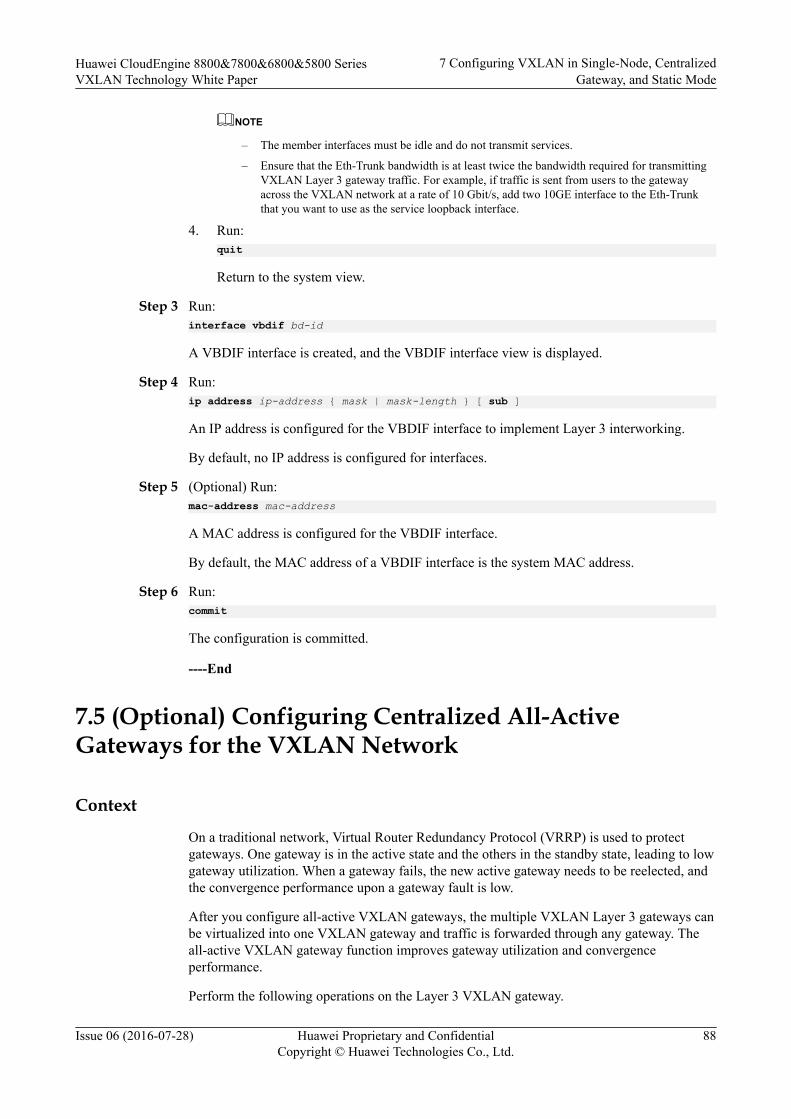
NOTE
– The member interfaces must be idle and do not transmit services.
– Ensure that the Eth-Trunk bandwidth is at least twice the bandwidth required for transmittingVXLAN Layer 3 gateway traffic. For example, if traffic is sent from users to the gatewayacross the VXLAN network at a rate of 10 Gbit/s, add two 10GE interface to the Eth-Trunkthat you want to use as the service loopback interface.
4. Run:quit
Return to the system view.
Step 3 Run:interface vbdif bd-id
A VBDIF interface is created, and the VBDIF interface view is displayed.
Step 4 Run:ip address ip-address { mask | mask-length } [ sub ]
An IP address is configured for the VBDIF interface to implement Layer 3 interworking.
By default, no IP address is configured for interfaces.
Step 5 (Optional) Run:mac-address mac-address
A MAC address is configured for the VBDIF interface.
By default, the MAC address of a VBDIF interface is the system MAC address.
Step 6 Run:commit
The configuration is committed.
----End
7.5 (Optional) Configuring Centralized All-ActiveGateways for the VXLAN Network
Context
On a traditional network, Virtual Router Redundancy Protocol (VRRP) is used to protectgateways. One gateway is in the active state and the others in the standby state, leading to lowgateway utilization. When a gateway fails, the new active gateway needs to be reelected, andthe convergence performance upon a gateway fault is low.
After you configure all-active VXLAN gateways, the multiple VXLAN Layer 3 gateways canbe virtualized into one VXLAN gateway and traffic is forwarded through any gateway. Theall-active VXLAN gateway function improves gateway utilization and convergenceperformance.
Perform the following operations on the Layer 3 VXLAN gateway.
Huawei CloudEngine 8800&7800&6800&5800 SeriesVXLAN Technology White Paper
7 Configuring VXLAN in Single-Node, CentralizedGateway, and Static Mode
Issue 06 (2016-07-28) Huawei Proprietary and ConfidentialCopyright © Huawei Technologies Co., Ltd.
88
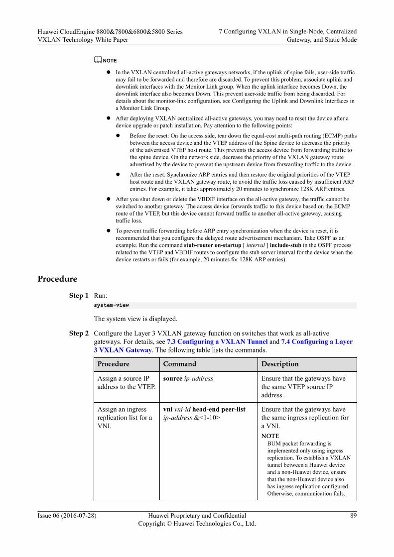
NOTE
l In the VXLAN centralized all-active gateways networks, if the uplink of spine fails, user-side trafficmay fail to be forwarded and therefore are discarded. To prevent this problem, associate uplink anddownlink interfaces with the Monitor Link group. When the uplink interface becomes Down, thedownlink interface also becomes Down. This prevent user-side traffic from being discarded. Fordetails about the monitor-link configuration, see Configuring the Uplink and Downlink Interfaces ina Monitor Link Group.
l After deploying VXLAN centralized all-active gateways, you may need to reset the device after adevice upgrade or patch installation. Pay attention to the following points:
l Before the reset: On the access side, tear down the equal-cost multi-path routing (ECMP) pathsbetween the access device and the VTEP address of the Spine device to decrease the priorityof the advertised VTEP host route. This prevents the access device from forwarding traffic tothe spine device. On the network side, decrease the priority of the VXLAN gateway routeadvertised by the device to prevent the upstream device from forwarding traffic to the device.
l After the reset: Synchronize ARP entries and then restore the original priorities of the VTEPhost route and the VXLAN gateway route, to avoid the traffic loss caused by insufficient ARPentries. For example, it takes approximately 20 minutes to synchronize 128K ARP entries.
l After you shut down or delete the VBDIF interface on the all-active gateway, the traffic cannot beswitched to another gateway. The access device forwards traffic to this device based on the ECMProute of the VTEP, but this device cannot forward traffic to another all-active gateway, causingtraffic loss.
l To prevent traffic forwarding before ARP entry synchronization when the device is reset, it isrecommended that you configure the delayed route advertisement mechanism. Take OSPF as anexample. Run the command stub-router on-startup [ interval ] include-stub in the OSPF processrelated to the VTEP and VBDIF routes to configure the stub server interval for the device when thedevice restarts or fails (for example, 20 minutes for 128K ARP entries).
Procedure
Step 1 Run:system-view
The system view is displayed.
Step 2 Configure the Layer 3 VXLAN gateway function on switches that work as all-activegateways. For details, see 7.3 Configuring a VXLAN Tunnel and 7.4 Configuring a Layer3 VXLAN Gateway. The following table lists the commands.
Procedure Command Description
Assign a source IPaddress to the VTEP.
source ip-address Ensure that the gateways havethe same VTEP source IPaddress.
Assign an ingressreplication list for aVNI.
vni vni-id head-end peer-listip-address &<1-10>
Ensure that the gateways havethe same ingress replication fora VNI.NOTE
BUM packet forwarding isimplemented only using ingressreplication. To establish a VXLANtunnel between a Huawei deviceand a non-Huawei device, ensurethat the non-Huawei device alsohas ingress replication configured.Otherwise, communication fails.
Huawei CloudEngine 8800&7800&6800&5800 SeriesVXLAN Technology White Paper
7 Configuring VXLAN in Single-Node, CentralizedGateway, and Static Mode
Issue 06 (2016-07-28) Huawei Proprietary and ConfidentialCopyright © Huawei Technologies Co., Ltd.
89

Procedure Command Description
Assign an IP addressto each VBDIFinterface.
ip address ip-address { mask |mask-length } [ sub ]
Ensure that the VBDIFinterfaces of the gateways havethe same IP address.
Assign a MACaddress to eachVBDIF interface.
mac-address mac-address Ensure that the VBDIFinterfaces of the gateways havethe same MAC address.
Step 3 If you want to configure the all-active gateway function on the device, configure a DFS groupto synchronize ARP entries between all-active gateways.
1. Run:dfs-group dfs-group-id
A DFS group is created and its view is displayed.
By default, no DFS group is created.
2. Run:source ip ip-address
The DFS group is bound to an IPv4 address.
By default, a DFS group is not bound to any IPv4 address.
3. (Optional) Run:udp port port-number
The UDP port number of the DFS group is set.
By default, the UDP port number of the DFS group is 61467.
4. Run:active-active-gateway
An all-active gateways is created and its view is displayed.
By default, no all-active gateway is created.
5. Run:peer ip-address [ vpn-instance vpn-instance-name ]
The all-active gateway peer is configured.
By default, no all-active gateway peer is configured.
NOTE
You can specify a maximum of fifteen IP addresses for all-active gateway peers in the all-activegateway view of a DFS group.
Step 4 Run:commit
The configuration is committed.
----End
Huawei CloudEngine 8800&7800&6800&5800 SeriesVXLAN Technology White Paper
7 Configuring VXLAN in Single-Node, CentralizedGateway, and Static Mode
Issue 06 (2016-07-28) Huawei Proprietary and ConfidentialCopyright © Huawei Technologies Co., Ltd.
90
7.6 (Optional) Configuring ARP Broadcast SuppressionWhen tenants communicate with each other for the first time, they send ARP requests. TheseARP requests are broadcast on Layer 2 networks and may cause a broadcast storm. To preventthis problem, ARP broadcast suppression can be enabled on Layer 2 VXLAN gateways.
Context
After you enable ARP broadcast suppression on Layer 2 VXLAN gateway, configure EthernetVirtual Network Border Gateway Protocol (EVN BGP) on Layer 2 and Layer 3 VXLANgateways to allow ARP broadcast suppression to take effect. EVN BGP can then generatehost information based on learned ARP entries. If a Layer 3 VXLAN gateway is enabled inthe VBDIF interface view to use EVN BGP to advertise information to Layer 2 VXLANgateways, the Layer 3 VXLAN gateway will advertise the host information generated byEVN BGP to Layer 2 VXLAN gateways. After the Layer 2 VXLAN gateways receive ARPbroadcast packets, they convert the ARP broadcast packets into unicast packets based on thelearned host information before forwarding the packets out. This decreases the number ofbroadcast packets in a BD, improving network performance.
Configuring BGP RRs is recommended to simplify BGP configuration. Layer 3 VXLANgateways are generally used as RRs, and Layer 2 VXLAN gateways as RR clients.
Procedure
Step 1 Configure EVN BGP on Layer 2 and Layer 3 VXLAN gateways to establish EVN BGP peerrelationships.
1. Run:system-viewThe system view is displayed.
2. Run:evn bgpThe EVN BGP view is displayed.
3. Run:source-address ip-addressA source address is configured for establishing an EVN BGP peer relationship. Thissource address can be used to generate a router ID, a next-hop address, and an EVNinstance's RD.By default, no source address is specified for establishing an EVN BGP peerrelationship.
4. Run:peer ip-addressAn EVN BGP peer address is specified.By default, no EVN BGP peer is specified.If a BGP RR is deployed, each VXLAN gateway only needs to establish an EVN BGPpeer relationship with the RR.
5. Run:commit
Huawei CloudEngine 8800&7800&6800&5800 SeriesVXLAN Technology White Paper
7 Configuring VXLAN in Single-Node, CentralizedGateway, and Static Mode
Issue 06 (2016-07-28) Huawei Proprietary and ConfidentialCopyright © Huawei Technologies Co., Ltd.
91
The configuration is committed.
Step 2 Configure a Layer 3 VXLAN gateway as a BGP RR.
1. Run:system-viewThe system view is displayed.
2. Run:evn bgpThe EVN BGP view is displayed.
3. Configure a dynamic or static EVN BGP RR. Dynamic and static RRs cannot coexist.Determine which type of RR to configure based on actual requirements.– To configure a dynamic RR, run the server enable command.
By default, no dynamic RR is configured.After a dynamic RR is configured, all devices that establish EVN BGP peerrelationships with the RR become the dynamic RR clients.
– To configure a static RR, run the peer ipv4-address reflect-client command.By default, no static RR is configured.Only the specified peer can become a static RR client.
4. Run:commitThe configuration is committed.
Step 3 Enable EVN BGP on a Layer 3 VXLAN gateway to collect host information.
1. Run:system-viewThe system view is displayed.
2. Run:interface vbdif bd-idThe VBDIF interface view is displayed.
3. Run:arp collect host enableEVN BGP is enabled to collect host information.By default, EVN BGP is disabled from collecting host information.
4. Run:commitThe configuration is committed.
Step 4 Enable Layer 2 and Layer 3 VXLAN gateways to use EVN BGP to advertise hostinformation.
1. Run:system-viewThe system view is displayed.
2. Run:host collect protocol bgpEVN BGP is enabled to advertise host information.
Huawei CloudEngine 8800&7800&6800&5800 SeriesVXLAN Technology White Paper
7 Configuring VXLAN in Single-Node, CentralizedGateway, and Static Mode
Issue 06 (2016-07-28) Huawei Proprietary and ConfidentialCopyright © Huawei Technologies Co., Ltd.
92

By default, EVN BGP is disabled from advertising host information.3. Run:
commitThe configuration is committed.
Step 5 Enable ARP broadcast suppression on a Layer 2 VXLAN gateway.
1. Run:system-viewThe system view is displayed.
2. Run:bridge-domain bd-idThe BD view is displayed.
3. Run:arp broadcast-suppress enableARP broadcast suppression is enabled.By default, ARP broadcast suppression is disabled.
4. Run:commitThe configuration is committed.
----End
7.7 (Optional) Disabling a VBDIF Interface from SendingARP Miss Messages
ContextWhen the device wants to communicate with another device in the same network segment, itqueries ARP entries to direct packet forwarding. If the device fails to find the correspondingARP entry from the forwarding plane, it sends an ARP Miss message to the CPU. The ARPMiss message will trigger the device to send an ARP broadcast packet to start ARP learning.In some cases, customers may want to limit the number of broadcast packets on the VXLANnetwork. You can then disable a VBDIF interface from sending ARP Miss messages toachieve this purpose.
After a VBDIF interface is disabled from sending ARP Miss messages, the device cannotlearn ARP entries from this VBDIF interface, so ARP entries must be manually configured onit.
Procedure
Step 1 Run:system-view
The system view is displayed.
Step 2 Run:interface vbdif bd-id
A VBDIF interface is created and the VBDIF interface view is displayed.
Huawei CloudEngine 8800&7800&6800&5800 SeriesVXLAN Technology White Paper
7 Configuring VXLAN in Single-Node, CentralizedGateway, and Static Mode
Issue 06 (2016-07-28) Huawei Proprietary and ConfidentialCopyright © Huawei Technologies Co., Ltd.
93
Step 3 Run:arp miss disable
The VBDIF interface is disabled from sending ARP Miss messages.
By default, a VBDIF interface can send ARP Miss messages.
Step 4 Run:commit
The configuration is committed.
----End
7.8 (Optional) Configuring Static ARP/MAC AddressEntries and MAC Address Limiting
Static ARP entries or MAC address entries can be configured for traffic forwarding, andMAC address limiting can be configured to improve VXLAN security.
Contextl Static ARP entries are manually configured and maintained. They can be neither aged
nor overwritten by dynamic ARP entries. Therefore, configuring static ARP entries onLayer 3 VXLAN gateways enhances communication security. If a static ARP entry isconfigured on a device, the device can communicate with a peer device that has aspecified IP address using only the specified MAC address. Network attackers cannotmodify the mapping between the IP and MAC addresses, which ensures communicationbetween the two devices.
l After the source NVE on a VXLAN tunnel receives broadcast, unknown unicast, andmulticast (BUM) packets, the local VTEP sends a copy of the BUM packets to everyVTEP in the ingress replication list. Configuring static MAC address entries helpsreduce broadcast traffic and prevent unauthorized data access from bogus users.
l The maximum number of MAC addresses that a device can learn can be configured tolimit the number of access users and prevent against attacks on MAC address tables. Ifthe device has learned the maximum number of MAC addresses allowed, no moreaddresses can be learned. The device can also be configured to discard packets afterlearning the maximum allowed number of MAC addresses, improving network security.
l If Layer 3 VXLAN gateway does not need to learn MAC addresses of packets in a BD,MAC address learning can be disabled from the BD to conserve MAC address entryresources. If the network topology of a VXLAN becomes stable and MAC address entrylearning is complete, MAC address learning can also be disabled.
Configuring static MAC address entries and MAC address limiting applies to Layer 2VXLAN gateways; configuring static ARP entries applies to Layer 3 VXLAN gateways;disabling MAC address limiting applies to both Layer 2 and Layer 3 VXLAN gateways.
Procedurel Configure a static ARP entry.
a. Run:system-viewThe system view is displayed.
Huawei CloudEngine 8800&7800&6800&5800 SeriesVXLAN Technology White Paper
7 Configuring VXLAN in Single-Node, CentralizedGateway, and Static Mode
Issue 06 (2016-07-28) Huawei Proprietary and ConfidentialCopyright © Huawei Technologies Co., Ltd.
94

b. Run:arp static ip-address mac-address vni vni-id source-ip source-ip peer-ip peer-ip
A static ARP entry is configured.By default, no static ARP entry is configured.
NOTE
ip-address must belong to the same network segment as the Layer 3 gateway's IP address.
c. Run:commitThe configuration is committed.
l Configure a static MAC address entry.
a. Run:system-viewThe system view is displayed.
b. Run:mac-address static mac-address bridge-domain bd-id source source-ip-address peer peer-ip vni vni-idA static MAC address entry is configured.By default, no static MAC address entry is configured.
c. Run:commitThe configuration is committed.
l Configure MAC address limiting.
NOTE
Only the standalone or stacked CE6855HI, CE6870EI, and CE7855EI support this function.
a. Run:system-viewThe system view is displayed.
b. Run:bridge-domain bd-idThe BD view is displayed.
c. Run:mac-address limit { action { discard | forward } | maximum max | alarm { disable | enable } } *
MAC address limiting is configured.By default, MAC address limiting is not configured.
d. Run:commitThe configuration is committed.
l Disable MAC address learning.
NOTE
Only the standalone or stacked CE6855HI, CE6870EI, and CE7855EI support this function.
a. Run:
Huawei CloudEngine 8800&7800&6800&5800 SeriesVXLAN Technology White Paper
7 Configuring VXLAN in Single-Node, CentralizedGateway, and Static Mode
Issue 06 (2016-07-28) Huawei Proprietary and ConfidentialCopyright © Huawei Technologies Co., Ltd.
95

system-view
The system view is displayed.b. Run:
bridge-domain bd-id
The BD view is displayed.c. Run:
mac-address learning disable
MAC address learning is disabled.By default, MAC address learning is enabled for a BD.
d. Run:commit
The configuration is committed.
----End
7.9 (Optional) Configuring a VXLAN BD Whitelist forMAC Address Flapping Detection
In specific VXLAN applications, when a device connects to a load balancing server equippedwith two network interface cards, the server's MAC address may be learned by two interfaceson the device. This is a normal situation where MAC address flapping detection is not needed.In this case, configure a VXLAN BD whitelist for MAC address flapping detection.
Context
By default, MAC address flapping detection is enabled globally. After a BD is added to aMAC address flapping detection whitelist, detection is not performed for this BD. Even ifMAC address flapping occurs in the BD, the occurrence generates neither an alarm nor arecord.
Procedure
Step 1 Run:system-view
The system view is displayed.
Step 2 Run:mac-address flapping detection exclude bridge-domain bd-id1 [ to bd-id2 ]
A VXLAN BD whitelist for MAC address flapping detection is configured.
By default, no VXLAN BD whitelist for MAC address flapping detection is configured.
Step 3 Run:commit
The configuration is committed.
----End
Huawei CloudEngine 8800&7800&6800&5800 SeriesVXLAN Technology White Paper
7 Configuring VXLAN in Single-Node, CentralizedGateway, and Static Mode
Issue 06 (2016-07-28) Huawei Proprietary and ConfidentialCopyright © Huawei Technologies Co., Ltd.
96

7.10 (Optional) Optimizing Load Balancing on the VXLANNetwork
Context
On a VXLAN network, VXLAN packets can be load balanced through ECMP or Eth-Trunks.To enable load balancing or improve the load balancing effect, enable either of the followingfunctions:l Enable load balancing of VXLAN packets through ECMP in optimized mode.l Enable an Eth-Trunk to load balance VXLAN packets in optimized mode.
NOTE
Only the CE6870EI supports this command.
Procedure
Step 1 Enable load balancing of VXLAN packets through ECMP in optimized mode.
1. Run:system-view
The system view is displayed.2. Run:
assign forward nvo3 ecmp hash enable
Load balancing of VXLAN packets through ECMP in optimized mode is enabled.By default, load balancing of VXLAN packets through ECMP in optimized mode isdisabled.
3. Run:commit
The configuration is committed.
Step 2 Enable an Eth-Trunk to load balance VXLAN packets in optimized mode.
1. Run:system-view
The system view is displayed.2. Run:
assign forward nvo3 eth-trunk hash enable
An Eth-Trunk is enabled to load balance VXLAN packets in optimized mode.By default, an Eth-Trunk is disabled from load balancing VXLAN packets in optimizedmode.
3. Run:commit
The configuration is committed.
----End
Huawei CloudEngine 8800&7800&6800&5800 SeriesVXLAN Technology White Paper
7 Configuring VXLAN in Single-Node, CentralizedGateway, and Static Mode
Issue 06 (2016-07-28) Huawei Proprietary and ConfidentialCopyright © Huawei Technologies Co., Ltd.
97
7.11 Checking the ConfigurationsAfter configuring VXLAN in centralized gateway mode for static tunnel establishment, checkVXLAN tunnel, VNI, and VBDIF interface information.
PrerequisitesVXLAN in centralized gateway mode has been configured for static tunnel establishment.
Procedurel Run the display bridge-domain [ bd-id [ brief | verbose ] ] command to check BD
configurations.l Run the display interface nve [ nve-number | main ] command to check NVE interface
information.l Run the display vxlan peer [ vni vni-id ] command to check ingress replication lists of a
VNI or all VNIs.l Run the display vxlan tunnel [ tunnel-id ] [ verbose ] command to check VXLAN
tunnel information.l Run the display vxlan vni [ vni-id [ verbose ] ] command to check VNI information.l Run the display interface vbdif [ bd-id ] command to check VBDIF interface
information and statistics.l Run the display dfs-group dfs-group-id active-active-gateway command to check
information of all-active gateways in a DFS group.l Run the display arp broadcast-suppress user bridge-domain bd-id command to check
the ARP broadcast suppression table of a BD.l Run the display arp [ network network-address [ network-mask | mask-length ] ] static
command to check static ARP entries.l Run the display mac-address static bridge-domain bd-id command to check static
MAC address entries in a BD.l Run the display mac-address limit bridge-domain bd-id command to check MAC
address limiting configurations of a BD.l Run the display mac-address flapping command to check the MAC address flapping
detection configuration.
----End
Huawei CloudEngine 8800&7800&6800&5800 SeriesVXLAN Technology White Paper
7 Configuring VXLAN in Single-Node, CentralizedGateway, and Static Mode
Issue 06 (2016-07-28) Huawei Proprietary and ConfidentialCopyright © Huawei Technologies Co., Ltd.
98

8 Configuring VXLAN in Single-Node,
Centralized Gateway, and BGP EVPN Mode
About This Chapter
When VXLAN in centralized gateway mode using BGP EVPN is deployed, traffic acrossnetwork segments is forwarded through Layer 3 VXLAN gateways to implement centralizedtraffic management.
Usage ScenarioAn enterprise has allocated VMs in different locations to a tenant. Some of the VMs reside onthe same network segment, and the others reside on different network segments. To allowcommunication between VMs, deploy Layer 2 and Layer 3 VXLAN gateways and establishVXLAN tunnels.
On the network shown in Figure 8-1, Server 2 and Server 3 belong to the same networksegment and access the VXLAN through Device 1 and Device 2, respectively; Server 1 andServer 2 belong to different network segments and both access the VXLAN through Device 1.l To allow VM 1 on Server 2 and VM 1 on Server 3 to communicate, deploy Layer 2
VXLAN gateways on Device 1 and Device 2 and establish a VXLAN tunnel betweenDevice 1 and Device 2 so that tenants on the same network segment can communicate.
l To allow VM 1 on Server 1 and VM 1 on Server 3 to communicate, deploy a Layer 3VXLAN gateway on Device 3 and establish a VXLAN tunnel between Device 1 andDevice 3 and between Device 2 and Device 3 so that tenants on different networksegments can communicate.
Huawei CloudEngine 8800&7800&6800&5800 SeriesVXLAN Technology White Paper
8 Configuring VXLAN in Single-Node, CentralizedGateway, and BGP EVPN Mode
Issue 06 (2016-07-28) Huawei Proprietary and ConfidentialCopyright © Huawei Technologies Co., Ltd.
99
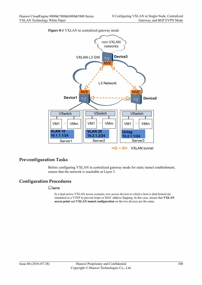
Figure 8-1 VXLAN in centralized gateway mode
VM1 VMm
VSwitch
...
Device1
Server1
L3 Network
Device2
VM1 VMm
VSwitch
...
Server3
VLAN 1010.1.1.1/24
Untag10.2.1.1/24
VXLAN L3 GW
VXLAN tunnel
non-VXLAN networks
VM1 VMm
VSwitch
...
Server2
VLAN 2010.2.1.2/24
Device3
NVE
NVENVE
Pre-configuration TasksBefore configuring VXLAN in centralized gateway mode for static tunnel establishment,ensure that the network is reachable at Layer 3.
Configuration ProceduresNOTE
In a dual-active VXLAN access scenario, two access devices to which a host is dual homed aresimulated as a VTEP to prevent loops or MAC address flapping. In this case, ensure that VXLANaccess point and VXLAN tunnel configuration on the two devices are the same.
Huawei CloudEngine 8800&7800&6800&5800 SeriesVXLAN Technology White Paper
8 Configuring VXLAN in Single-Node, CentralizedGateway, and BGP EVPN Mode
Issue 06 (2016-07-28) Huawei Proprietary and ConfidentialCopyright © Huawei Technologies Co., Ltd.
100

Figure 8-2 Flowchart for configuring intra-segment communication through centralizedVXLAN gateways
Configure a VXLAN tunnel.
Mandatory
Optional
Configure static MAC address entries and MAC address
limiting.
Configure a service access point.
Configure MAC address flapping detection and a
VXLAN BD whitelist.
NOTETo implement intra-segment communication through centralized VXLAN gateways, configure onlystatic MAC address entries and MAC address limiting described in 7.8 (Optional) Configuring StaticARP/MAC Address Entries and MAC Address Limiting.
Huawei CloudEngine 8800&7800&6800&5800 SeriesVXLAN Technology White Paper
8 Configuring VXLAN in Single-Node, CentralizedGateway, and BGP EVPN Mode
Issue 06 (2016-07-28) Huawei Proprietary and ConfidentialCopyright © Huawei Technologies Co., Ltd.
101
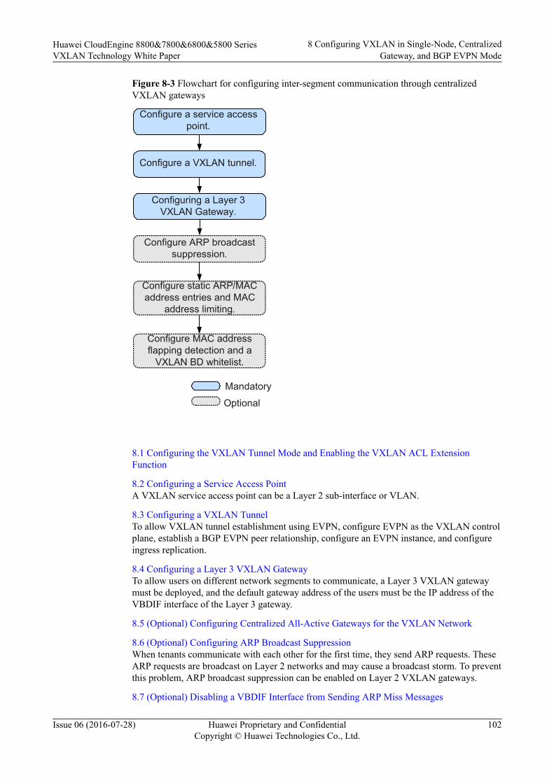
Figure 8-3 Flowchart for configuring inter-segment communication through centralizedVXLAN gateways
Configure a VXLAN tunnel.
Configure ARP broadcast suppression.
Mandatory
Optional
Configure static ARP/MAC address entries and MAC
address limiting.
Configure a service access point.
Configuring a Layer 3 VXLAN Gateway.
Configure MAC address flapping detection and a
VXLAN BD whitelist.
8.1 Configuring the VXLAN Tunnel Mode and Enabling the VXLAN ACL ExtensionFunction
8.2 Configuring a Service Access PointA VXLAN service access point can be a Layer 2 sub-interface or VLAN.
8.3 Configuring a VXLAN TunnelTo allow VXLAN tunnel establishment using EVPN, configure EVPN as the VXLAN controlplane, establish a BGP EVPN peer relationship, configure an EVPN instance, and configureingress replication.
8.4 Configuring a Layer 3 VXLAN GatewayTo allow users on different network segments to communicate, a Layer 3 VXLAN gatewaymust be deployed, and the default gateway address of the users must be the IP address of theVBDIF interface of the Layer 3 gateway.
8.5 (Optional) Configuring Centralized All-Active Gateways for the VXLAN Network
8.6 (Optional) Configuring ARP Broadcast SuppressionWhen tenants communicate with each other for the first time, they send ARP requests. TheseARP requests are broadcast on Layer 2 networks and may cause a broadcast storm. To preventthis problem, ARP broadcast suppression can be enabled on Layer 2 VXLAN gateways.
8.7 (Optional) Disabling a VBDIF Interface from Sending ARP Miss Messages
Huawei CloudEngine 8800&7800&6800&5800 SeriesVXLAN Technology White Paper
8 Configuring VXLAN in Single-Node, CentralizedGateway, and BGP EVPN Mode
Issue 06 (2016-07-28) Huawei Proprietary and ConfidentialCopyright © Huawei Technologies Co., Ltd.
102

8.8 (Optional) Configuring Static ARP/MAC Address Entries and MAC Address LimitingStatic ARP entries or MAC address entries can be configured for traffic forwarding, andMAC address limiting can be configured to improve VXLAN security.
8.9 (Optional) Configuring a VXLAN BD Whitelist for MAC Address Flapping DetectionIn specific VXLAN applications, when a device connects to a load balancing server equippedwith two network interface cards, the server's MAC address may be learned by two interfaceson the device. This is a normal situation where MAC address flapping detection is not needed.In this case, configure a VXLAN BD whitelist for MAC address flapping detection.
8.10 (Optional) Optimizing Load Balancing on the VXLAN Network
8.11 Checking the ConfigurationsAfter configuring VXLAN in centralized gateway mode for dynamic tunnel establishment,check VXLAN tunnel, VNI, and VBDIF interface information.
Huawei CloudEngine 8800&7800&6800&5800 SeriesVXLAN Technology White Paper
8 Configuring VXLAN in Single-Node, CentralizedGateway, and BGP EVPN Mode
Issue 06 (2016-07-28) Huawei Proprietary and ConfidentialCopyright © Huawei Technologies Co., Ltd.
103

8.1 Configuring the VXLAN Tunnel Mode and Enablingthe VXLAN ACL Extension Function
Contextl Configuring a tunnel mode: You need to set the tunnel mode to VXLAN when
configuring the VXLAN feature; otherwise, the configurations do not take effect.l Enabling the VXLAN ACL extension function: By default, the VXLAN ACL extension
function is disabled on the device. If you configure other ACL resource-consumingservices, such as MQC, simplified ACL, traffic policing, and BD traffic statisticscollection, on the device deployed with VXLAN services, there is high probability thatthe other services fail to be configured. You can enable the VXLAN ACL extensionfunction to lower the configuration failure probability.
To ensure normal forwarding of VXLAN packets, the VXLAN tunnel mode must have beenconfigured and the VXLAN ACL extension function must have been enabled on Layer 2 andLayer 3 VXLAN gateways.
NOTE
You can configure the VXLAN tunnel mode and enable the VXLAN ACL extension function only onthe CE6870EI.
Procedure
Step 1 Run:system-view
The system view is displayed.
Step 2 Run:ip tunnel mode vxlan
The tunnel mode is set to VXLAN.
By default, the tunnel mode is VXLAN.
Step 3 Run:assign forward nvo3 acl extend enable
The VXLAN ACL extension function is enabled.
By default, the VXLAN ACL extension function is disabled.
Step 4 Run:commit
The configuration is committed.
----End
Follow-up ProcedureAfter configuring the VXLAN tunnel mode and enabling the VXLAN ACL extensionfunction, you need to save the configuration and restart the switch to make the configurationtake effect.
Huawei CloudEngine 8800&7800&6800&5800 SeriesVXLAN Technology White Paper
8 Configuring VXLAN in Single-Node, CentralizedGateway, and BGP EVPN Mode
Issue 06 (2016-07-28) Huawei Proprietary and ConfidentialCopyright © Huawei Technologies Co., Ltd.
104
8.2 Configuring a Service Access PointA VXLAN service access point can be a Layer 2 sub-interface or VLAN.
ContextWhen a Layer 2 sub-interface is used as a service access point, different encapsulation typescan be configured for the sub-interface to transmit various types of data packets. After a Layer2 sub-interface is added to a BD, the sub-interface can transmit data packets through this BD.Table 8-1 describes the different encapsulation types.
Table 8-1 Traffic encapsulation types
TrafficEncapsulationType
Description
dot1q If a Dot1q sub-interface receives a single-tagged VLAN packet, thesub-interface forwards only the packet with a specifie VLAN ID. If aDot1q sub-interface receives a double-tagged VLAN packet, the sub-interface forwards only the packet with a specified outer VLAN ID.l When performing VXLAN encapsulation on packets, a Dot1q
Layer 2 sub-interface removes the outer tags of the packets.l When performing VXLAN decapsulation on packets, a Dot1q
Layer 2 sub-interface replaces the VLAN tags with specifiedVLAN tags if the inner packets carry VLAN tags, or addsspecified VLAN tags to the packets if the inner packets do notcarry VXLAN tags.
When setting the encapsulation type to dot1q for a Layer 2 sub-interface, note the following:l The VLAN IDs specified for the Layer 2 sub-interface cannot be
the same as either the VLAN IDs of packets allowed to passthrough the corresponding Layer 2 interfaces or the MUX VLANIDs.
l Layer 2 and Layer 3 sub-interfaces cannot have the same VLANIDs specified.
Huawei CloudEngine 8800&7800&6800&5800 SeriesVXLAN Technology White Paper
8 Configuring VXLAN in Single-Node, CentralizedGateway, and BGP EVPN Mode
Issue 06 (2016-07-28) Huawei Proprietary and ConfidentialCopyright © Huawei Technologies Co., Ltd.
105

TrafficEncapsulationType
Description
untag An untagged Layer 2 sub-interface receives only packets that do notcarry VLAN tags.l When performing VXLAN encapsulation on packets, an untagged
Layer 2 sub-interface does not add any VLAN tag to the packets.l When performing VXLAN decapsulation on packets, an untagged
Layer 2 sub-interface removes the VLAN tags of single-taggedinner packets or the outer VLAN tags of double-tagged innerpackets.
When setting the encapsulation type to untag for a Layer 2 sub-interface, note the following:l Ensure that the corresponding physical interface of the sub-
interface does not have any configuration, and is removed fromthe default VLAN.
l Untagged Layer 2 sub-interfaces can be configured only for Layer2 physical interfaces and Eth-Trunk interfaces.
l An interface can have only one untagged Layer 2 sub-interfaceconfigured.
qinq A QinQ sub-interface receives only tagged packets with specifiedinner and outer VLAN tags.l When performing VXLAN encapsulation on packets, a QinQ sub-
interface removes two VLAN tags from packets if the action ofthe Layer 2 sub-interface is set to removing two VLAN tags andmaintains the VLAN tags of packets if the action of the Layer 2sub-interface is not set to removing two VLAN tags.
l When performing VXLAN decapsulation on packets, a QinQ sub-interface adds two specific VLAN tags to packets if the action ofthe Layer 2 sub-interface is set to removing two VLAN tags andmaintain the VLAN tags of packets if the action of the Layer 2sub-interface is not set to removing two VLAN tags.
NOTEThe traffic behavior for QinQ interfaces bound to the same BD must be thesame.
QinQ interfaces do not support DHCP Snooping or VBDIF and cannot bebound to the same BD as Dot1q sub-interfaces. A QinQ interface can haveonly one outer VLAN tag and one inner VLAN tag.
Huawei CloudEngine 8800&7800&6800&5800 SeriesVXLAN Technology White Paper
8 Configuring VXLAN in Single-Node, CentralizedGateway, and BGP EVPN Mode
Issue 06 (2016-07-28) Huawei Proprietary and ConfidentialCopyright © Huawei Technologies Co., Ltd.
106

TrafficEncapsulationType
Description
default A default Layer 2 sub-interface receives all packets, irrespective ofwhether the packets carry VLAN tags.When performing VXLAN encapsulation and decapsulation onpackets, a default Layer 2 sub-interface does not process VLAN tagsof the packets.When setting the encapsulation type to default for a Layer 2 sub-interface, note the following:l Ensure that the interface for the Layer 2 sub-interface is not added
to any VLAN.l Default Layer 2 sub-interfaces can be configured only for Layer 2
physical interfaces and Eth-Trunk interfaces.l If a default Layer 2 sub-interface is created for an interface, the
interface cannot have other types of Layer 2 sub-interfacesconfigured.
NOTEWhen a sub-interface that is configured with dot1q and QinQ receives double-tagged VLAN packets, theQinQ sub-interface preferentially processes the packets. For example, if a dot1q and QinQ sub-interfacecarries the VLAN ID of 10 for dot1q and outer VLAN ID of 10 and inner VLAN ID of 20 for QinQ andreceives a packet with the outer VLAN ID of 10 and inner VLAN ID of 20, the QinQ sub-interfacepreferentially processes the packet. If a dot1q and QinQ sub-interface carries the VLAN ID of 10 fordot1q and outer VLAN ID of 10 and inner VLAN ID of 20 for QinQ and receives a packet with theouter VLAN ID of 10 and inner VLAN ID of non-20, the dot1q sub-interface preferentially processesthe packet.
If a VLAN is used as a service access point, it can be bound to a BD for data packets in theVLAN to be transmitted through this BD.
Configure a service access point on a Layer 2 gateway.
Procedure
Step 1 Run:system-view
The system view is displayed.
Step 2 Run:bridge-domain bd-id
A BD is created, and the BD view is displayed.
By default, no BD is created.
Step 3 (Optional) Run:description description
A description is configured for the BD.
By default, no description is configured for a BD.
Huawei CloudEngine 8800&7800&6800&5800 SeriesVXLAN Technology White Paper
8 Configuring VXLAN in Single-Node, CentralizedGateway, and BGP EVPN Mode
Issue 06 (2016-07-28) Huawei Proprietary and ConfidentialCopyright © Huawei Technologies Co., Ltd.
107

Step 4 Run:quit
Return to the system view.
Step 5 (Optional) Set the port mode to VXLAN access. (You do not need to perform this step on theCE6870EI.)
1. Run:interface interface-type interface-number
The interface view is displayed.2. Run:
port nvo3 mode access
The port mode is set to VXLAN access, so that the port can send common IP packetswith the destination UDP port number of VXLAN packets (defaults to 4789) to theVXLAN.By default, the port mode is not set to VXLAN access, that is, the port cannot sendcommon IP packets with the destination UDP port number of VXLAN packets (defaultsto 4789) to the VXLAN.
3. Run:quit
Return to the system view.
Step 6 Configure a service access point.l Configure a VLAN as a service access point.
NOTE
– In a distributed gateway scenario, a VLAN cannot be configured as a VXLAN service accesspoint.
– You cannot bind a VLAN to a BD while configuring the ARP broadcast suppression function.After a VLAN is configured as a VXLAN service access point, do not configure ARPbroadcast suppression.
– After a VLAN is bound to a BD, the BD becomes the broadcast domain. Therefore, otherservice configurations such as DHCP Snooping and IGMP Snooping in the VLAN becomeinvalid.
– VLAN and BD use 1:1 mapping. That is, a VLAN can be bound to only one BD, and only oneVLAN can be bound to a BD.
a. Run:bridge-domain bd-id
The view of an existing BD is displayed.b. Run:
l2 binding vlan vlan-id
A global VLAN is bound to the BD.By default, VLANs are not bound to any BD.
NOTE
Before performing this step, ensure that a global VLAN has been created. After binding theglobal VLAN to the BD, add the related device interfaces to the VLAN.
c. Run:commit
The configuration is committed.
Huawei CloudEngine 8800&7800&6800&5800 SeriesVXLAN Technology White Paper
8 Configuring VXLAN in Single-Node, CentralizedGateway, and BGP EVPN Mode
Issue 06 (2016-07-28) Huawei Proprietary and ConfidentialCopyright © Huawei Technologies Co., Ltd.
108
l Configure a Layer 2 sub-interface as a service access point.
a. Run:interface interface-type interface-number.subnum mode l2
A Layer 2 sub-interface is created, and the sub-interface view is displayed.By default, no Layer 2 sub-interface is created.
NOTE
Before running this command, ensure that the Layer 2 interface for which a Layer 2 sub-interface is created does not have the port link-type dot1q-tunnel command configuration.If this configuration exists, run the undo port link-type command to delete theconfiguration.
b. Run:encapsulation { dot1q [ vid ce-vid ] | default | untag | qinq [ vid pe-vid ce-vid ce-vid ] }
An encapsulation type is configured for the Layer 2 sub-interface.By default, no encapsulation type is configured for Layer 2 sub-interfaces.
c. (Optional) Run:rewrite pop double
The sub-interface is enabled to remove double VLAN tags from received packets ifthe encapsulation type of the sub-interface is set to QinQ in Step 6.b.By default, a Layer 2 sub-interface with the encapsulation type being QinQ isenabled to transparently transmit received packets.
d. Run:bridge-domain bd-id
The Layer 2 sub-interface is added to a BD so that the sub-interface can transmitdata packets through this BD.By default, Layer 2 sub-interfaces are not added to any BD.
NOTE
After a Layer 2 sub-interface with the flow encapsulation type set to default is added to aBD, you cannot create a VBDIF interface for the BD.
e. Run:commit
The configuration is committed.
----End
8.3 Configuring a VXLAN TunnelTo allow VXLAN tunnel establishment using EVPN, configure EVPN as the VXLAN controlplane, establish a BGP EVPN peer relationship, configure an EVPN instance, and configureingress replication.
Context
In centralized VXLAN gateway scenarios, perform the following steps on the Layer 2 andLayer 3 VXLAN gateways to use EVPN for establishing VXLAN tunnels:
1. Configure EVPN as the VXLAN control plane. Subsequent EVPN configurations canthen be performed.
Huawei CloudEngine 8800&7800&6800&5800 SeriesVXLAN Technology White Paper
8 Configuring VXLAN in Single-Node, CentralizedGateway, and BGP EVPN Mode
Issue 06 (2016-07-28) Huawei Proprietary and ConfidentialCopyright © Huawei Technologies Co., Ltd.
109
2. Configure a BGP EVPN peer relationship. Configure VXLAN gateways to establishBGP EVPN peer relationships so that they can exchange EVPN routes. If an RR hasbeen deployed, each VXLAN gateway only needs to establish a BGP EVPN peerrelationship with the RR.
3. (Optional) Configure an RR. The deployment of RRs reduces the number of BGP EVPNpeer relationships to be established, simplifying configuration. A live-network devicecan be used as an RR, or a standalone RR can be deployed. Layer 3 VXLAN gatewaysare generally used as RRs, and Layer 2 VXLAN gateways as RR clients.
4. Configure an EVPN instance. EVPN instances are used to receive and advertise EVPNroutes.
5. Configure ingress replication. After ingress replication is configured for a VNI, thesystem uses BGP EVPN to construct a list of remote VTEPs. After a VXLAN gatewayreceives BUM packets, its sends a copy of the BUM packets to every VXLAN gatewayin the list.
Procedure
Step 1 Configure EVPN as the VXLAN control plane.1. Run:
system-view
The system view is displayed.2. Run:
evpn-overlay enable
EVPN is configured as the VXLAN control plane.
By default, EVPN is not configured as the VXLAN control plane.3. Run:
commit
The configuration is committed.
Step 2 Configure a BGP EVPN peer relationship.1. Run:
bgp as-number [ instance instance-name ]
BGP is enabled, and the BGP or BGP multi-instance view is displayed.
By default, the BGP is disabled. If an RR has been deployed, each VXLAN gatewayonly needs to establish a BGP EVPN peer relationship with the RR.
2. (Optional) Run:router-id ipv4-address
A router ID is set.
By default, no BGP Router ID is configured, and the Router ID configured for the routemanagement module through the router id command is used.
3. Run:peer ipv4-address as-number as-number
The peer device is configured as a BGP peer.
By default, no BGP peer is configured, and no AS number is specified for a peer or peergroup.
Huawei CloudEngine 8800&7800&6800&5800 SeriesVXLAN Technology White Paper
8 Configuring VXLAN in Single-Node, CentralizedGateway, and BGP EVPN Mode
Issue 06 (2016-07-28) Huawei Proprietary and ConfidentialCopyright © Huawei Technologies Co., Ltd.
110
4. (Optional) Run:peer ipv4-address connect-interface interface-type interface-number [ ipv4-source-address ]
A source interface and a source address are specified to set up a TCP connection with theBGP peer.
By default, the outbound interface of a BGP packet serves as the source interface of aBGP packet.
NOTE
When loopback interfaces are used to establish a BGP connection, running the peer connect-interface command on both ends is recommended to ensure the connectivity. If this command isrun on only one end, the BGP connection may fail to be established.
5. (Optional) Run:peer ipv4-address ebgp-max-hop [ hop-count ]
The maximum number of hops is set for an EBGP EVPN connection.
The default value of hop-count is 255.
In most cases, a directly connected physical link must be available between EBGPEVPN peers. If you want to establish EBGP EVPN peer relationships between indirectlyconnected peers, run the peer ebgp-max-hop command. The command also canconfigure the maximum number of hops for an EBGP EVPN connection.
NOTE
When the IP address of loopback interface to establish an EBGP EVPN peer relationship, run thepeer ebgp-max-hop (of which the value of hop-count is not less than 2) command. Otherwise, thepeer relationship fails to be established.
6. Run:l2vpn-family evpn
The BGP-EVPN address family view or BGP multi-instance EVPN view is displayed.
By default, the BGP-EVPN address family or BGP multi-instance EVPN view isdisabled.
7. Run:peer { ipv4-address | group-name } enable
The device is enabled to exchange EVPN routes with a specified peer or peer group.
By default, only the peer in the BGP IPv4 unicast address family view is automaticallyenabled.
8. (Optional) Run:peer { group-name | ipv4-address } route-policy route-policy-name { import | export }
A routing policy is specified for routes received from or to be advertised to a BGP EVPNpeer or peer group.
After the routing policy is applied, the routes received from or to be advertised to aspecified BGP EVPN peer or peer group will be filtered, ensuring that only desiredroutes are imported or advertised. This configuration helps manage routes and reducerequired routing entries and system resources.
9. (Optional) Run:
Huawei CloudEngine 8800&7800&6800&5800 SeriesVXLAN Technology White Paper
8 Configuring VXLAN in Single-Node, CentralizedGateway, and BGP EVPN Mode
Issue 06 (2016-07-28) Huawei Proprietary and ConfidentialCopyright © Huawei Technologies Co., Ltd.
111
peer { group-name | ipv4-address } mac-limit number [ percentage ] [ alert-only | idle-forever | idle-timeout times ]
The maximum number of MAC advertisement routes that can be received from eachpeer is configured.
If an EVPN instance may import many invalid MAC advertisement routes from peersand these routes occupy a large proportion of the total MAC advertisement routes. If thereceived MAC advertisement routes exceed the specified maximum number, the systemdisplays an alarm, instructing users to check the validity of the MAC advertisementroutes received in the EVPN instance.
10. Run:quit
Exit from the BGP-EVPN address family view or BGP multi-instance EVPN view.11. Run:
quit
Exit from the BGP or BGP multi-instance view.12. Run:
commit
The configuration is committed.
Step 3 (Optional) Configure a Layer 3 VXLAN gateway as an RR. If an RR is configured, eachVXLAN gateway only needs to establish a BGP EVPN peer relationship with the RR,reducing the number of BGP EVPN peer relationships to be established and simplifyingconfiguration.1. Run:
bgp as-number [ instance instance-name ]
The BGP or BGP multi-instance view is displayed.2. Run:
l2vpn-family evpn
The BGP-EVPN address family view or BGP multi-instance EVPN view is displayed.3. Run:
peer { ipv4-address | group-name } enable
The device is enabled to exchange EVPN routes with a specified peer or peer group.
By default, only the peer in the BGP IPv4 unicast address family view is automaticallyenabled.
4. (Optional) Run:peer { ipv4-address | group-name } next-hop-invariable
The device is prevented from changing the next hop address of a route when advertisingthe route to an EBGP peer.
By default, a BGP EVPN speaker changes the next hops of routes to the interface that ituses to establish EBGP EVPN peer relationships before advertising these routes toEBGP EVPN peers.
5. Run:peer { ipv4-address | group-name } reflect-client
The device is configured as an RR and an RR client is specified.
Huawei CloudEngine 8800&7800&6800&5800 SeriesVXLAN Technology White Paper
8 Configuring VXLAN in Single-Node, CentralizedGateway, and BGP EVPN Mode
Issue 06 (2016-07-28) Huawei Proprietary and ConfidentialCopyright © Huawei Technologies Co., Ltd.
112

By default, the route reflector and its client are not configured.6. Run:
undo policy vpn-target
The function to filter received EVPN routes based on VPN targets is disabled. If you donot perform this step, the RR will fail to receive and reflect the routes sent by clients.
7. Run:quit
Exit from the BGP-EVPN address family view or BGP multi-instance EVPN view.8. Run:
quit
Exit from the BGP or BGP multi-instance view.9. Run:
commit
The configuration is committed.
Step 4 Configure an EVPN instance.1. Run:
bridge-domain bd-id
The BD view is displayed.
By default, no bridge domain is created.2. Run:
vxlan vni vni-id
A VNI is created and mapped to the BD.
By default, no VNI is created.3. Run:
evpn
An EVPN instance is created.
By default, no EVPN instance is created for VXLANs.4. Run:
route-distinguisher { route-distinguisher | auto }
An RD is configured for the EVPN instance. The two ends of a VXLAN tunnel canshare an RD or use different RDs.
By default, no RD is configured for BD EVPN instances.5. Run:
vpn-target { vpn-target &<1-8> | auto } [ both | export-extcommunity | import-extcommunity ]
VPN targets are configured for the EVPN instance. The export VPN target of the localend must be the same as the import VPN target of the remote end, and the import VPNtarget of the local end must be the same as the export VPN target of the remote end.
By default, no VPN target is configured for BD EVPN instances.6. (Optional) Run:
import route-policy policy-name
Huawei CloudEngine 8800&7800&6800&5800 SeriesVXLAN Technology White Paper
8 Configuring VXLAN in Single-Node, CentralizedGateway, and BGP EVPN Mode
Issue 06 (2016-07-28) Huawei Proprietary and ConfidentialCopyright © Huawei Technologies Co., Ltd.
113
The current EVPN instance is associated with an import routing policy.
By default, an EVPN instance matches the export VPN targets of received routes againstits import VPN targets to determine whether to import these routes. To control routeimport more precisely, perform this step to associate the EVPN instance with an importrouting policy and set attributes for eligible routes.
7. (Optional) Run:export route-policy policy-name
The current EVPN instance is associated with an export routing policy.
By default, an EVPN instance adds all VPN targets in the export VPN target list toEVPN routes to be advertised to its peers. To control route export more precisely,perform this step to associate the EVPN instance with an export routing policy and setattributes for eligible routes.
8. Run:quit
The EVPN instance view is exited.9. Run:
quit
Return to the system view.10. Run:
commit
The configuration is committed.
Step 5 Configure an ingress replication list.1. Run:
interface nve nve-number
An NVE interface is created, and the NVE interface view is displayed.2. Run:
source ip-address
An IP address is configured for the source VTEP.
By default, no IP address is configured for any source VTEP.3. Run:
vni vni-id head-end peer-list protocol bgp
An ingress replication list is configured.
By default, no ingress replication list is configured for any VNI.
NOTE
BUM packet forwarding is implemented only using ingress replication. To establish a VXLANtunnel between a Huawei device and a non-Huawei device, ensure that the non-Huawei devicealso has ingress replication configured. Otherwise, communication fails.
4. Run:quit
Return to the system view.5. Run:
Huawei CloudEngine 8800&7800&6800&5800 SeriesVXLAN Technology White Paper
8 Configuring VXLAN in Single-Node, CentralizedGateway, and BGP EVPN Mode
Issue 06 (2016-07-28) Huawei Proprietary and ConfidentialCopyright © Huawei Technologies Co., Ltd.
114
commit
The configuration is committed.
----End
8.4 Configuring a Layer 3 VXLAN GatewayTo allow users on different network segments to communicate, a Layer 3 VXLAN gatewaymust be deployed, and the default gateway address of the users must be the IP address of theVBDIF interface of the Layer 3 gateway.
Context
A tenant is identified by a VNI. VNIs can be mapped to BDs in 1:1 mode so that a BD canfunction as a VXLAN network entity to transmit VXLAN data packets. A VBDIF interface isa Layer 3 logical interface created for a BD. After an IP address is configured for a VBDIFinterface of a BD, the VBDIF interface can function as the gateway for tenants in the BD forLayer 3 forwarding. VBDIF interfaces allow Layer 3 communication between VXLANs ondifferent network segments and between VXLANs and non-VXLANs, and implement Layer2 network access to a Layer 3 network.
VBDIF interfaces are configured on Layer 3 VXLAN gateways for inter-segmentcommunication, and are not needed in the case of intra-segment communication.
NOTE
The DHCP relay function can be configured on the VBDIF interface so that hosts can request IPaddresses from the external DHCP server.
Procedure
Step 1 Run:system-view
The system view is displayed.
Step 2 Configure a service loopback interface. (You do not need to perform this step on theCE6855HI, CE6870EI, and CE7855EI.)1. Run:
interface eth-trunk trunk-id
The Eth-Trunk interface view is displayed.2. Run:
service type tunnel
Service loopback is enabled on the Eth-Trunk to loop back service packets of theVXLAN Layer 3 gateway.
NOTE
– One service loopback interface takes effect for a maximum of 2000 VBDIF interfaces.
– After you run the service type tunnel command on an Eth-Trunk, the Eth-Trunk and itsphysical member interfaces can only be used for the VXLAN Layer 3 gateway and cannot beconfigured with other services.
3. Run:
Huawei CloudEngine 8800&7800&6800&5800 SeriesVXLAN Technology White Paper
8 Configuring VXLAN in Single-Node, CentralizedGateway, and BGP EVPN Mode
Issue 06 (2016-07-28) Huawei Proprietary and ConfidentialCopyright © Huawei Technologies Co., Ltd.
115
trunkport interface-type { interface-number1 [ to interface-number2 ] }
Member interfaces are added to the Eth-Trunk.
NOTE
– The member interfaces must be idle and do not transmit services.
– Ensure that the Eth-Trunk bandwidth is at least twice the bandwidth required for transmittingVXLAN Layer 3 gateway traffic. For example, if traffic is sent from users to the gatewayacross the VXLAN network at a rate of 10 Gbit/s, add two 10GE interface to the Eth-Trunkthat you want to use as the service loopback interface.
4. Run:quit
Return to the system view.
Step 3 Run:interface vbdif bd-id
A VBDIF interface is created, and the VBDIF interface view is displayed.
Step 4 Run:ip address ip-address { mask | mask-length } [ sub ]
An IP address is configured for the VBDIF interface to implement Layer 3 interworking.
By default, no IP address is configured for interfaces.
Step 5 (Optional) Run:mac-address mac-address
A MAC address is configured for the VBDIF interface.
By default, the MAC address of a VBDIF interface is the system MAC address.
Step 6 Run:commit
The configuration is committed.
----End
8.5 (Optional) Configuring Centralized All-ActiveGateways for the VXLAN Network
Context
On a traditional network, Virtual Router Redundancy Protocol (VRRP) is used to protectgateways. One gateway is in the active state and the others in the standby state, leading to lowgateway utilization. When a gateway fails, the new active gateway needs to be reelected, andthe convergence performance upon a gateway fault is low.
After you configure all-active VXLAN gateways, the multiple VXLAN Layer 3 gateways canbe virtualized into one VXLAN gateway and traffic is forwarded through any gateway. Theall-active VXLAN gateway function improves gateway utilization and convergenceperformance.
Huawei CloudEngine 8800&7800&6800&5800 SeriesVXLAN Technology White Paper
8 Configuring VXLAN in Single-Node, CentralizedGateway, and BGP EVPN Mode
Issue 06 (2016-07-28) Huawei Proprietary and ConfidentialCopyright © Huawei Technologies Co., Ltd.
116
Perform the following operations on the Layer 3 VXLAN gateway.
NOTE
l In the VXLAN centralized all-active gateways networks, if the uplink of spine fails, user-side trafficmay fail to be forwarded and therefore are discarded. To prevent this problem, associate uplink anddownlink interfaces with the Monitor Link group. When the uplink interface becomes Down, thedownlink interface also becomes Down. This prevent user-side traffic from being discarded. Fordetails about the monitor-link configuration, see Configuring the Uplink and Downlink Interfaces ina Monitor Link Group.
l After deploying VXLAN centralized all-active gateways, you may need to reset the device after adevice upgrade or patch installation. Pay attention to the following points:
l Before the reset: On the access side, tear down the equal-cost multi-path routing (ECMP) pathsbetween the access device and the VTEP address of the Spine device to decrease the priorityof the advertised VTEP host route. This prevents the access device from forwarding traffic tothe spine device. On the network side, decrease the priority of the VXLAN gateway routeadvertised by the device to prevent the upstream device from forwarding traffic to the device.
l After the reset: Synchronize ARP entries and then restore the original priorities of the VTEPhost route and the VXLAN gateway route, to avoid the traffic loss caused by insufficient ARPentries. For example, it takes approximately 20 minutes to synchronize 128K ARP entries.
l After you shut down or delete the VBDIF interface on the all-active gateway, the traffic cannot beswitched to another gateway. The access device forwards traffic to this device based on the ECMProute of the VTEP, but this device cannot forward traffic to another all-active gateway, causingtraffic loss.
l To prevent traffic forwarding before ARP entry synchronization when the device is reset, it isrecommended that you configure the delayed route advertisement mechanism. Take OSPF as anexample. Run the command stub-router on-startup [ interval ] include-stub in the OSPF processrelated to the VTEP and VBDIF routes to configure the stub server interval for the device when thedevice restarts or fails (for example, 20 minutes for 128K ARP entries).
Procedure
Step 1 Run:system-view
The system view is displayed.
Step 2 Configure the Layer 3 VXLAN gateway function on switches that work as all-activegateways. For details, see 8.3 Configuring a VXLAN Tunnel and 8.4 Configuring a Layer3 VXLAN Gateway. The following table lists the commands.
Procedure Command Description
Assign an ingressreplication list for aVNI.
vni vni-id head-end peer-listip-address &<1-10>
Ensure that the gateways havethe same ingress replication fora VNI.NOTE
BUM packet forwarding isimplemented only using ingressreplication. To establish a VXLANtunnel between a Huawei deviceand a non-Huawei device, ensurethat the non-Huawei device alsohas ingress replication configured.Otherwise, communication fails.
Huawei CloudEngine 8800&7800&6800&5800 SeriesVXLAN Technology White Paper
8 Configuring VXLAN in Single-Node, CentralizedGateway, and BGP EVPN Mode
Issue 06 (2016-07-28) Huawei Proprietary and ConfidentialCopyright © Huawei Technologies Co., Ltd.
117

Procedure Command Description
Assign an IP addressto each VBDIFinterface.
ip address ip-address { mask |mask-length } [ sub ]
Ensure that the VBDIFinterfaces of the gateways havethe same IP address.
Assign a MACaddress to eachVBDIF interface.
mac-address mac-address Ensure that the VBDIFinterfaces of the gateways havethe same MAC address.
Step 3 If you want to configure the all-active gateway function on the device, configure a DFS groupto synchronize ARP entries between all-active gateways.
1. Run:dfs-group dfs-group-id
A DFS group is created and its view is displayed.
By default, no DFS group is created.
2. Run:source ip ip-address
The DFS group is bound to an IPv4 address.
By default, a DFS group is not bound to any IPv4 address.
3. (Optional) Run:udp port port-number
The UDP port number of the DFS group is set.
By default, the UDP port number of the DFS group is 61467.
4. Run:active-active-gateway
An all-active gateways is created and its view is displayed.
By default, no all-active gateway is created.
5. Run:peer ip-address [ vpn-instance vpn-instance-name ]
The all-active gateway peer is configured.
By default, no all-active gateway peer is configured.
NOTE
You can specify a maximum of fifteen IP addresses for all-active gateway peers in the all-activegateway view of a DFS group.
Step 4 Run:commit
The configuration is committed.
----End
Huawei CloudEngine 8800&7800&6800&5800 SeriesVXLAN Technology White Paper
8 Configuring VXLAN in Single-Node, CentralizedGateway, and BGP EVPN Mode
Issue 06 (2016-07-28) Huawei Proprietary and ConfidentialCopyright © Huawei Technologies Co., Ltd.
118
8.6 (Optional) Configuring ARP Broadcast SuppressionWhen tenants communicate with each other for the first time, they send ARP requests. TheseARP requests are broadcast on Layer 2 networks and may cause a broadcast storm. To preventthis problem, ARP broadcast suppression can be enabled on Layer 2 VXLAN gateways.
Context
After you enable ARP broadcast suppression on a Layer 2 VXLAN gateway, configureBorder Gateway Protocol Ethernet Virtual Private Network (BGP EVPN) on Layer 2 andLayer 3 VXLAN gateways to allow ARP broadcast suppression to take effect. BGP EVPNcan then generate host information based on learned ARP entries and advertise the hostinformation to Layer 2 VXLAN gateways. After the Layer 2 VXLAN gateways receive ARPbroadcast packets, they convert the ARP broadcast packets into unicast packets based on thelearned host information before forwarding the packets out. This decreases the number ofbroadcast packets in a BD, improving network performance.
Configuring BGP RRs is recommended to simplify BGP configuration. Layer 3 VXLANgateways are generally used as RRs, and Layer 2 VXLAN gateways as RR clients.
Procedure
Step 1 Configure BGP EVPN on Layer 2 and Layer 3 VXLAN gateways to advertise hostinformation learned by Layer 2 VXLAN gateways.
1. Run:system-viewThe system view is displayed.
2. Run:bgp as-number [ instance instance-name ]The BGP or BGP multi-instance view is displayed.
3. Run:l2vpn-family evpnThe BGP-EVPN address family view or BGP multi-instance EVPN view is displayed.By default, the BGP-EVPN address family or BGP multi-instance EVPN view isdisabled.
4. Configure advertisement of ARP or IRB routes to implement ARP broadcastsuppression. The following two configurations cannot coexist.– To configure ARP route advertisement, run the peer { ipv4-address | group-name }
advertise arp command.– To configure IRB route advertisement, run the peer { ipv4-address | group-name }
advertise irb command.5. Run:
commitThe configuration is committed.
Step 2 Enable BGP EVPN on a Layer 3 VXLAN gateway to collect host information.
1. Run:
Huawei CloudEngine 8800&7800&6800&5800 SeriesVXLAN Technology White Paper
8 Configuring VXLAN in Single-Node, CentralizedGateway, and BGP EVPN Mode
Issue 06 (2016-07-28) Huawei Proprietary and ConfidentialCopyright © Huawei Technologies Co., Ltd.
119
system-viewThe system view is displayed.
2. Run:interface vbdif bd-idThe VBDIF interface view is displayed.
3. Run:arp collect host enableBGP EVPN is enabled to collect host information.By default, BGP EVPN is disabled from collecting host information.
4. Run:commitThe configuration is committed.
Step 3 Enable ARP broadcast suppression on a Layer 2 VXLAN gateway.
1. Run:system-viewThe system view is displayed.
2. Run:bridge-domain bd-idThe BD view is displayed.
3. Run:arp broadcast-suppress enableARP broadcast suppression is enabled.By default, ARP broadcast suppression is disabled.
4. Run:commitThe configuration is committed.
----End
8.7 (Optional) Disabling a VBDIF Interface from SendingARP Miss Messages
Context
When the device wants to communicate with another device in the same network segment, itqueries ARP entries to direct packet forwarding. If the device fails to find the correspondingARP entry from the forwarding plane, it sends an ARP Miss message to the CPU. The ARPMiss message will trigger the device to send an ARP broadcast packet to start ARP learning.In some cases, customers may want to limit the number of broadcast packets on the VXLANnetwork. You can then disable a VBDIF interface from sending ARP Miss messages toachieve this purpose.
After a VBDIF interface is disabled from sending ARP Miss messages, the device cannotlearn ARP entries from this VBDIF interface, so ARP entries must be manually configured onit.
Huawei CloudEngine 8800&7800&6800&5800 SeriesVXLAN Technology White Paper
8 Configuring VXLAN in Single-Node, CentralizedGateway, and BGP EVPN Mode
Issue 06 (2016-07-28) Huawei Proprietary and ConfidentialCopyright © Huawei Technologies Co., Ltd.
120

Procedure
Step 1 Run:system-view
The system view is displayed.
Step 2 Run:interface vbdif bd-id
A VBDIF interface is created and the VBDIF interface view is displayed.
Step 3 Run:arp miss disable
The VBDIF interface is disabled from sending ARP Miss messages.
By default, a VBDIF interface can send ARP Miss messages.
Step 4 Run:commit
The configuration is committed.
----End
8.8 (Optional) Configuring Static ARP/MAC AddressEntries and MAC Address Limiting
Static ARP entries or MAC address entries can be configured for traffic forwarding, andMAC address limiting can be configured to improve VXLAN security.
Contextl Static ARP entries are manually configured and maintained. They can be neither aged
nor overwritten by dynamic ARP entries. Therefore, configuring static ARP entries onLayer 3 VXLAN gateways enhances communication security. If a static ARP entry isconfigured on a device, the device can communicate with a peer device that has aspecified IP address using only the specified MAC address. Network attackers cannotmodify the mapping between the IP and MAC addresses, which ensures communicationbetween the two devices.
l After the source NVE on a VXLAN tunnel receives broadcast, unknown unicast, andmulticast (BUM) packets, the local VTEP sends a copy of the BUM packets to everyVTEP in the ingress replication list. Configuring static MAC address entries helpsreduce broadcast traffic and prevent unauthorized data access from bogus users.
l The maximum number of MAC addresses that a device can learn can be configured tolimit the number of access users and prevent against attacks on MAC address tables. Ifthe device has learned the maximum number of MAC addresses allowed, no moreaddresses can be learned. The device can also be configured to discard packets afterlearning the maximum allowed number of MAC addresses, improving network security.
l If Layer 3 VXLAN gateway does not need to learn MAC addresses of packets in a BD,MAC address learning can be disabled from the BD to conserve MAC address entryresources. If the network topology of a VXLAN becomes stable and MAC address entrylearning is complete, MAC address learning can also be disabled.
Huawei CloudEngine 8800&7800&6800&5800 SeriesVXLAN Technology White Paper
8 Configuring VXLAN in Single-Node, CentralizedGateway, and BGP EVPN Mode
Issue 06 (2016-07-28) Huawei Proprietary and ConfidentialCopyright © Huawei Technologies Co., Ltd.
121
Configuring static MAC address entries and MAC address limiting applies to Layer 2VXLAN gateways; configuring static ARP entries applies to Layer 3 VXLAN gateways;disabling MAC address limiting applies to both Layer 2 and Layer 3 VXLAN gateways.
Procedurel Configure a static ARP entry.
a. Run:system-viewThe system view is displayed.
b. Run:arp static ip-address mac-address vni vni-id source-ip source-ip peer-ip peer-ip
A static ARP entry is configured.By default, no static ARP entry is configured.
NOTE
ip-address must belong to the same network segment as the Layer 3 gateway's IP address.
c. Run:commitThe configuration is committed.
l Configure a static MAC address entry.
a. Run:system-viewThe system view is displayed.
b. Run:mac-address static mac-address bridge-domain bd-id source source-ip-address peer peer-ip vni vni-idA static MAC address entry is configured.By default, no static MAC address entry is configured.
c. Run:commitThe configuration is committed.
l Configure MAC address limiting.
NOTE
Only the standalone or stacked CE6855HI, CE6870EI, and CE7855EI support this function.
a. Run:system-viewThe system view is displayed.
b. Run:bridge-domain bd-idThe BD view is displayed.
c. Run:mac-address limit { action { discard | forward } | maximum max | alarm { disable | enable } } *
MAC address limiting is configured.
Huawei CloudEngine 8800&7800&6800&5800 SeriesVXLAN Technology White Paper
8 Configuring VXLAN in Single-Node, CentralizedGateway, and BGP EVPN Mode
Issue 06 (2016-07-28) Huawei Proprietary and ConfidentialCopyright © Huawei Technologies Co., Ltd.
122

By default, MAC address limiting is not configured.d. Run:
commitThe configuration is committed.
l Disable MAC address learning.
NOTE
Only the standalone or stacked CE6855HI, CE6870EI, and CE7855EI support this function.
a. Run:system-viewThe system view is displayed.
b. Run:bridge-domain bd-idThe BD view is displayed.
c. Run:mac-address learning disableMAC address learning is disabled.By default, MAC address learning is enabled for a BD.
d. Run:commitThe configuration is committed.
----End
8.9 (Optional) Configuring a VXLAN BD Whitelist forMAC Address Flapping Detection
In specific VXLAN applications, when a device connects to a load balancing server equippedwith two network interface cards, the server's MAC address may be learned by two interfaceson the device. This is a normal situation where MAC address flapping detection is not needed.In this case, configure a VXLAN BD whitelist for MAC address flapping detection.
ContextBy default, MAC address flapping detection is enabled globally. After a BD is added to aMAC address flapping detection whitelist, detection is not performed for this BD. Even ifMAC address flapping occurs in the BD, the occurrence generates neither an alarm nor arecord.
Procedure
Step 1 Run:system-view
The system view is displayed.
Step 2 Run:mac-address flapping detection exclude bridge-domain bd-id1 [ to bd-id2 ]
A VXLAN BD whitelist for MAC address flapping detection is configured.
Huawei CloudEngine 8800&7800&6800&5800 SeriesVXLAN Technology White Paper
8 Configuring VXLAN in Single-Node, CentralizedGateway, and BGP EVPN Mode
Issue 06 (2016-07-28) Huawei Proprietary and ConfidentialCopyright © Huawei Technologies Co., Ltd.
123
By default, no VXLAN BD whitelist for MAC address flapping detection is configured.
Step 3 Run:commit
The configuration is committed.
----End
8.10 (Optional) Optimizing Load Balancing on the VXLANNetwork
Context
On a VXLAN network, VXLAN packets can be load balanced through ECMP or Eth-Trunks.To enable load balancing or improve the load balancing effect, enable either of the followingfunctions:l Enable load balancing of VXLAN packets through ECMP in optimized mode.l Enable an Eth-Trunk to load balance VXLAN packets in optimized mode.
NOTE
Only the CE6870EI supports this command.
Procedure
Step 1 Enable load balancing of VXLAN packets through ECMP in optimized mode.
1. Run:system-viewThe system view is displayed.
2. Run:assign forward nvo3 ecmp hash enableLoad balancing of VXLAN packets through ECMP in optimized mode is enabled.By default, load balancing of VXLAN packets through ECMP in optimized mode isdisabled.
3. Run:commitThe configuration is committed.
Step 2 Enable an Eth-Trunk to load balance VXLAN packets in optimized mode.
1. Run:system-viewThe system view is displayed.
2. Run:assign forward nvo3 eth-trunk hash enableAn Eth-Trunk is enabled to load balance VXLAN packets in optimized mode.By default, an Eth-Trunk is disabled from load balancing VXLAN packets in optimizedmode.
Huawei CloudEngine 8800&7800&6800&5800 SeriesVXLAN Technology White Paper
8 Configuring VXLAN in Single-Node, CentralizedGateway, and BGP EVPN Mode
Issue 06 (2016-07-28) Huawei Proprietary and ConfidentialCopyright © Huawei Technologies Co., Ltd.
124

3. Run:commitThe configuration is committed.
----End
8.11 Checking the ConfigurationsAfter configuring VXLAN in centralized gateway mode for dynamic tunnel establishment,check VXLAN tunnel, VNI, and VBDIF interface information.
PrerequisitesVXLAN in centralized gateway mode has been configured for dynamic tunnel establishment.
Procedurel Run the display bridge-domain [ bd-id [ brief | verbose ] ] command to check BD
configurations.l Run the display interface nve [ nve-number | main ] command to check NVE interface
information.l Run the display evpn vpn-instance [ vpn-instance-name ] command to check EVPN
instance information.l Run the display bgp [ instance instance-name ] evpn peer [ [ ipv4-address ] verbose ]
command to check BGP EVPN peer information.l Run the display vxlan peer [ vni vni-id ] command to check ingress replication lists of a
VNI or all VNIs.l Run the display vxlan tunnel [ tunnel-id ] [ verbose ] command to check VXLAN
tunnel information.l Run the display vxlan vni [ vni-id [ verbose ] ] command to check VNI information.l Run the display interface vbdif [ bd-id ] command to check VBDIF interface
information and statistics.l Run the display dfs-group dfs-group-id active-active-gateway command to check
information of all-active gateways in a DFS group.l Run the display arp broadcast-suppress user bridge-domain bd-id command to check
the ARP broadcast suppression table of a BD.l Run the display arp [ network network-address [ network-mask | mask-length ] ] static
command to check static ARP entries.l Run the display mac-address static bridge-domain bd-id command to check static
MAC address entries in a BD.l Run the display mac-address limit bridge-domain bd-id command to check MAC
address limiting configurations of a BD.l Run the display mac-address flapping command to check the MAC address flapping
detection configuration.l Run the display bgp [ instance instance-name ] evpn all routing-table command to
check EVPN route information.l Run the display mac-address inactive [ evn ] [ slot slot-id ] command to check the
MAC address entries that fail to be delivered.
Huawei CloudEngine 8800&7800&6800&5800 SeriesVXLAN Technology White Paper
8 Configuring VXLAN in Single-Node, CentralizedGateway, and BGP EVPN Mode
Issue 06 (2016-07-28) Huawei Proprietary and ConfidentialCopyright © Huawei Technologies Co., Ltd.
125

l Run the display mac-address total-number evn [ vlan vlan-id ] command to check thenumber of EVN MAC address entries.
l Run the display mac-address evn [ vlan vlan-id ] command to check EVN MACaddress entries.
----End
Huawei CloudEngine 8800&7800&6800&5800 SeriesVXLAN Technology White Paper
8 Configuring VXLAN in Single-Node, CentralizedGateway, and BGP EVPN Mode
Issue 06 (2016-07-28) Huawei Proprietary and ConfidentialCopyright © Huawei Technologies Co., Ltd.
126

9 Configuring VXLAN in Single-Node,
Distributed Gateway, and MP-BGP Mode
About This Chapter
Distributed VXLAN gateways can be configured to address problems that occur in legacycentralized VXLAN gateway networking, for example, forwarding paths are not optimal, andthe ARP entry specification is a bottleneck.
Usage Scenario
Figure 9-1 Centralized VXLAN gateway networking
跨子网流量
Leaf1 Leaf2
Spine1 Spine2L3 Gateway
L2 Gateway
Server110.1.1.1/24
Server210.10.1.1/24 Server3
10.20.1.1/24Server410.10.1.2/24
Huawei CloudEngine 8800&7800&6800&5800 SeriesVXLAN Technology White Paper
9 Configuring VXLAN in Single-Node, DistributedGateway, and MP-BGP Mode
Issue 06 (2016-07-28) Huawei Proprietary and ConfidentialCopyright © Huawei Technologies Co., Ltd.
127

In legacy networking, a centralized Layer 3 gateway is deployed on a spine node. On thenetwork shown in Figure 9-1, packets across different networks must be forwarded through acentralized Layer 3 gateway, resulting in the following problems:l Forwarding paths are not optimal. All Layer 3 traffic must be transmitted to the
centralized Layer 3 gateway for forwarding.l The ARP entry specification is a bottleneck. ARP entries must be generated for tenants
on the Layer 3 gateway. However, only a limited number of ARP entries can beconfigured for the Layer 3 gateway, impeding data center network expansion.
To address these problems, distributed VXLAN gateways can be configured. On the networkshown in Figure 9-2, Server 1 and Server 2 on different network segments both connect toLeaf 1. When Server 1 and Server 2 communicate, traffic is forwarded only through Leaf 1,not through any spine node.
Figure 9-2 Distributed VXLAN gateway networking
Inter-segment traffic
Leaf1 Leaf2
Spine1 Spine2
L3 GatewayL2 Gateway
Server110.1.1.1/24
Server210.10.1.1/24
Server310.20.1.1/24
Server410.10.1.2/24
Distributed VXLAN gateway networking has the following characteristics:l Flexible deployment. A leaf node can function as both Layer 2 and Layer 3 VXLAN
gateways.l Improved network expansion capabilities. A leaf node only needs to learn the ARP
entries of servers attached to it. A centralized Layer 3 gateway in the same scenario,however, has to learn the ARP entries of all servers on the network. Therefore, the ARPentry specification is no longer a bottleneck on a distributed VXLAN gateway.
l Enhanced network performance: Changing broadcast packets to unicast packets, leafnodes can determine whether to broadcast ARP request packets received from tenants orservers. This reduces the number of ARP broadcast packets and improves networkperformance.
Huawei CloudEngine 8800&7800&6800&5800 SeriesVXLAN Technology White Paper
9 Configuring VXLAN in Single-Node, DistributedGateway, and MP-BGP Mode
Issue 06 (2016-07-28) Huawei Proprietary and ConfidentialCopyright © Huawei Technologies Co., Ltd.
128
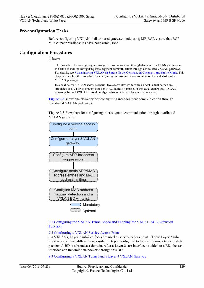
Pre-configuration TasksBefore configuring VXLAN in distributed gateway mode using MP-BGP, ensure that BGPVPNv4 peer relationships have been established.
Configuration ProceduresNOTE
The procedure for configuring intra-segment communication through distributed VXLAN gateways isthe same as that for configuring intra-segment communication through centralized VXLAN gateways.For details, see 7 Configuring VXLAN in Single-Node, Centralized Gateway, and Static Mode. Thischapter describes the procedure for configuring inter-segment communication through distributedVXLAN gateways.In a dual-active VXLAN access scenario, two access devices to which a host is dual homed aresimulated as a VTEP to prevent loops or MAC address flapping. In this case, ensure that VXLANaccess point and VXLAN tunnel configuration on the two devices are the same.
Figure 9-3 shows the flowchart for configuring inter-segment communication throughdistributed VXLAN gateways.
Figure 9-3 Flowchart for configuring inter-segment communication through distributedVXLAN gateways
Configure a Layer 3 VXLAN gateway.
Configure ARP broadcast suppression.
Mandatory
Optional
Configure static ARP/MAC address entries and MAC
address limiting.
Configure a service access point.
Configure MAC address flapping detection and a
VXLAN BD whitelist.
9.1 Configuring the VXLAN Tunnel Mode and Enabling the VXLAN ACL ExtensionFunction
9.2 Configuring a VXLAN Service Access PointOn VXLANs, Layer 2 sub-interfaces are used as service access points. These Layer 2 sub-interfaces can have different encapsulation types configured to transmit various types of datapackets. A BD is a broadcast domain. After a Layer 2 sub-interface is added to a BD, the sub-interface can transmit data packets through this BD.
9.3 Configuring a VXLAN Tunnel and a Layer 3 VXLAN Gateway
Huawei CloudEngine 8800&7800&6800&5800 SeriesVXLAN Technology White Paper
9 Configuring VXLAN in Single-Node, DistributedGateway, and MP-BGP Mode
Issue 06 (2016-07-28) Huawei Proprietary and ConfidentialCopyright © Huawei Technologies Co., Ltd.
129
To isolate tenants at Layer 3, VPN is generally used. In a distributed VXLAN gatewayscenario, when Layer 3 communication is implemented through Layer 3 gateways, the Layer3 gateways must be bound to VPN instances. Then VXLAN tunnels can be establishedthrough BGP VPN peers. A Layer 3 VXLAN gateway performs VXLAN encapsulation anddecapsulation to allow inter-segment VXLAN communication and access to externalnetworks.
9.4 (Optional) Configuring ARP Broadcast SuppressionWhen tenants communicate with each other for the first time, they send ARP requests. TheseARP requests are broadcast on Layer 2 networks and may cause a broadcast storm. To preventthis problem, ARP broadcast suppression can be enabled on VXLAN gateways.
9.5 (Optional) Disabling a VBDIF Interface from Sending ARP Miss Messages
9.6 (Optional) Configuring Static ARP/MAC Address Entries and MAC Address LimitingStatic ARP entries or MAC address entries can be configured for traffic forwarding, andMAC address limiting can be configured to improve VXLAN security.
9.7 (Optional) Configuring a VXLAN BD Whitelist for MAC Address Flapping DetectionIn specific VXLAN applications, when a device connects to a load balancing server equippedwith two network interface cards, the server's MAC address may be learned by two interfaceson the device. This is a normal situation where MAC address flapping detection is not needed.In this case, configure a VXLAN BD whitelist for MAC address flapping detection.
9.8 (Optional) Optimizing Load Balancing on the VXLAN Network
9.9 Checking the ConfigurationsAfter configuring VXLAN in distributed gateway mode using MP-BGP, check theconfigurations, and you can find that VXLAN tunnels are dynamically established and are inthe Up state.
Huawei CloudEngine 8800&7800&6800&5800 SeriesVXLAN Technology White Paper
9 Configuring VXLAN in Single-Node, DistributedGateway, and MP-BGP Mode
Issue 06 (2016-07-28) Huawei Proprietary and ConfidentialCopyright © Huawei Technologies Co., Ltd.
130
9.1 Configuring the VXLAN Tunnel Mode and Enablingthe VXLAN ACL Extension Function
Contextl Configuring a tunnel mode: You need to set the tunnel mode to VXLAN when
configuring the VXLAN feature; otherwise, the configurations do not take effect.l Enabling the VXLAN ACL extension function: By default, the VXLAN ACL extension
function is disabled on the device. If you configure other ACL resource-consumingservices, such as MQC, simplified ACL, traffic policing, and BD traffic statisticscollection, on the device deployed with VXLAN services, there is high probability thatthe other services fail to be configured. You can enable the VXLAN ACL extensionfunction to lower the configuration failure probability.
To ensure normal forwarding of VXLAN packets, the VXLAN tunnel mode must have beenconfigured and the VXLAN ACL extension function must have been enabled on Layer 2 andLayer 3 VXLAN gateways.
NOTE
You can configure the VXLAN tunnel mode and enable the VXLAN ACL extension function only onthe CE6870EI.
Procedure
Step 1 Run:system-view
The system view is displayed.
Step 2 Run:ip tunnel mode vxlan
The tunnel mode is set to VXLAN.
By default, the tunnel mode is VXLAN.
Step 3 Run:assign forward nvo3 acl extend enable
The VXLAN ACL extension function is enabled.
By default, the VXLAN ACL extension function is disabled.
Step 4 Run:commit
The configuration is committed.
----End
Follow-up ProcedureAfter configuring the VXLAN tunnel mode and enabling the VXLAN ACL extensionfunction, you need to save the configuration and restart the switch to make the configurationtake effect.
Huawei CloudEngine 8800&7800&6800&5800 SeriesVXLAN Technology White Paper
9 Configuring VXLAN in Single-Node, DistributedGateway, and MP-BGP Mode
Issue 06 (2016-07-28) Huawei Proprietary and ConfidentialCopyright © Huawei Technologies Co., Ltd.
131

9.2 Configuring a VXLAN Service Access PointOn VXLANs, Layer 2 sub-interfaces are used as service access points. These Layer 2 sub-interfaces can have different encapsulation types configured to transmit various types of datapackets. A BD is a broadcast domain. After a Layer 2 sub-interface is added to a BD, the sub-interface can transmit data packets through this BD.
ContextWhen a Layer 2 sub-interface is used as a service access point, different encapsulation typescan be configured for the sub-interface to transmit various types of data packets. After a Layer2 sub-interface is added to a BD, the sub-interface can transmit data packets through this BD.Table 9-1 describes the different encapsulation types.
Table 9-1 Traffic encapsulation types
TrafficEncapsulationType
Description
dot1q If a Dot1q sub-interface receives a single-tagged VLAN packet, thesub-interface forwards only the packet with a specifie VLAN ID. If aDot1q sub-interface receives a double-tagged VLAN packet, the sub-interface forwards only the packet with a specified outer VLAN ID.l When performing VXLAN encapsulation on packets, a Dot1q
Layer 2 sub-interface removes the outer tags of the packets.l When performing VXLAN decapsulation on packets, a Dot1q
Layer 2 sub-interface replaces the VLAN tags with specifiedVLAN tags if the inner packets carry VLAN tags, or addsspecified VLAN tags to the packets if the inner packets do notcarry VXLAN tags.
When setting the encapsulation type to dot1q for a Layer 2 sub-interface, note the following:l The VLAN IDs specified for the Layer 2 sub-interface cannot be
the same as either the VLAN IDs of packets allowed to passthrough the corresponding Layer 2 interfaces or the MUX VLANIDs.
l Layer 2 and Layer 3 sub-interfaces cannot have the same VLANIDs specified.
Huawei CloudEngine 8800&7800&6800&5800 SeriesVXLAN Technology White Paper
9 Configuring VXLAN in Single-Node, DistributedGateway, and MP-BGP Mode
Issue 06 (2016-07-28) Huawei Proprietary and ConfidentialCopyright © Huawei Technologies Co., Ltd.
132
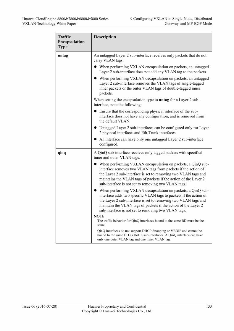
TrafficEncapsulationType
Description
untag An untagged Layer 2 sub-interface receives only packets that do notcarry VLAN tags.l When performing VXLAN encapsulation on packets, an untagged
Layer 2 sub-interface does not add any VLAN tag to the packets.l When performing VXLAN decapsulation on packets, an untagged
Layer 2 sub-interface removes the VLAN tags of single-taggedinner packets or the outer VLAN tags of double-tagged innerpackets.
When setting the encapsulation type to untag for a Layer 2 sub-interface, note the following:l Ensure that the corresponding physical interface of the sub-
interface does not have any configuration, and is removed fromthe default VLAN.
l Untagged Layer 2 sub-interfaces can be configured only for Layer2 physical interfaces and Eth-Trunk interfaces.
l An interface can have only one untagged Layer 2 sub-interfaceconfigured.
qinq A QinQ sub-interface receives only tagged packets with specifiedinner and outer VLAN tags.l When performing VXLAN encapsulation on packets, a QinQ sub-
interface removes two VLAN tags from packets if the action ofthe Layer 2 sub-interface is set to removing two VLAN tags andmaintains the VLAN tags of packets if the action of the Layer 2sub-interface is not set to removing two VLAN tags.
l When performing VXLAN decapsulation on packets, a QinQ sub-interface adds two specific VLAN tags to packets if the action ofthe Layer 2 sub-interface is set to removing two VLAN tags andmaintain the VLAN tags of packets if the action of the Layer 2sub-interface is not set to removing two VLAN tags.
NOTEThe traffic behavior for QinQ interfaces bound to the same BD must be thesame.
QinQ interfaces do not support DHCP Snooping or VBDIF and cannot bebound to the same BD as Dot1q sub-interfaces. A QinQ interface can haveonly one outer VLAN tag and one inner VLAN tag.
Huawei CloudEngine 8800&7800&6800&5800 SeriesVXLAN Technology White Paper
9 Configuring VXLAN in Single-Node, DistributedGateway, and MP-BGP Mode
Issue 06 (2016-07-28) Huawei Proprietary and ConfidentialCopyright © Huawei Technologies Co., Ltd.
133
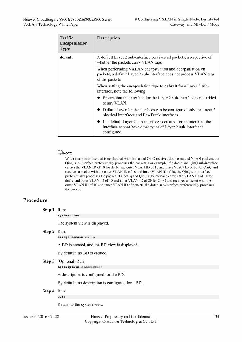
TrafficEncapsulationType
Description
default A default Layer 2 sub-interface receives all packets, irrespective ofwhether the packets carry VLAN tags.When performing VXLAN encapsulation and decapsulation onpackets, a default Layer 2 sub-interface does not process VLAN tagsof the packets.When setting the encapsulation type to default for a Layer 2 sub-interface, note the following:l Ensure that the interface for the Layer 2 sub-interface is not added
to any VLAN.l Default Layer 2 sub-interfaces can be configured only for Layer 2
physical interfaces and Eth-Trunk interfaces.l If a default Layer 2 sub-interface is created for an interface, the
interface cannot have other types of Layer 2 sub-interfacesconfigured.
NOTEWhen a sub-interface that is configured with dot1q and QinQ receives double-tagged VLAN packets, theQinQ sub-interface preferentially processes the packets. For example, if a dot1q and QinQ sub-interfacecarries the VLAN ID of 10 for dot1q and outer VLAN ID of 10 and inner VLAN ID of 20 for QinQ andreceives a packet with the outer VLAN ID of 10 and inner VLAN ID of 20, the QinQ sub-interfacepreferentially processes the packet. If a dot1q and QinQ sub-interface carries the VLAN ID of 10 fordot1q and outer VLAN ID of 10 and inner VLAN ID of 20 for QinQ and receives a packet with theouter VLAN ID of 10 and inner VLAN ID of non-20, the dot1q sub-interface preferentially processesthe packet.
Procedure
Step 1 Run:system-view
The system view is displayed.
Step 2 Run:bridge-domain bd-id
A BD is created, and the BD view is displayed.
By default, no BD is created.
Step 3 (Optional) Run:description description
A description is configured for the BD.
By default, no description is configured for a BD.
Step 4 Run:quit
Return to the system view.
Huawei CloudEngine 8800&7800&6800&5800 SeriesVXLAN Technology White Paper
9 Configuring VXLAN in Single-Node, DistributedGateway, and MP-BGP Mode
Issue 06 (2016-07-28) Huawei Proprietary and ConfidentialCopyright © Huawei Technologies Co., Ltd.
134

Step 5 (Optional) Set the port mode to VXLAN access. (You do not need to perform this step on theCE6870EI.)
1. Run:interface interface-type interface-number
The interface view is displayed.2. Run:
port nvo3 mode access
The port mode is set to VXLAN access, so that the port can send common IP packetswith the destination UDP port number of VXLAN packets (defaults to 4789) to theVXLAN.By default, the port mode is not set to VXLAN access, that is, the port cannot sendcommon IP packets with the destination UDP port number of VXLAN packets (defaultsto 4789) to the VXLAN.
3. Run:quit
Return to the system view.
Step 6 Run:interface interface-type interface-number.subnum mode l2
A Layer 2 sub-interface is created, and the sub-interface view is displayed.
By default, no Layer 2 sub-interface is created.
Before running this command, ensure that the Layer 2 interface for which a Layer 2 sub-interface is created does not have the port link-type dot1q-tunnel command configuration. Ifthis configuration exists, run the undo port link-type command to delete the configuration.
Step 7 Run:encapsulation { dot1q [ vid ce-vid ] | default | untag | qinq [ vid pe-vid ce-vid ce-vid ] }
An encapsulation type is configured for the Layer 2 sub-interface.
By default, no encapsulation type is configured for Layer 2 sub-interfaces.
Step 8 (Optional) Run:rewrite pop double
The sub-interface is enabled to remove double VLAN tags from received packets if theencapsulation type of the sub-interface is set to QinQ in Step 7.
By default, a Layer 2 sub-interface with the encapsulation type being QinQ is enabled totransparently transmit received packets.
Step 9 Run:bridge-domain bd-id
The Layer 2 sub-interface is added to a BD so that the sub-interface can transmit data packetsthrough this BD.
By default, the Layer 2 sub-interface is not added to a BD.
Step 10 Run:commit
Huawei CloudEngine 8800&7800&6800&5800 SeriesVXLAN Technology White Paper
9 Configuring VXLAN in Single-Node, DistributedGateway, and MP-BGP Mode
Issue 06 (2016-07-28) Huawei Proprietary and ConfidentialCopyright © Huawei Technologies Co., Ltd.
135
The configuration is committed.
----End
9.3 Configuring a VXLAN Tunnel and a Layer 3 VXLANGateway
To isolate tenants at Layer 3, VPN is generally used. In a distributed VXLAN gatewayscenario, when Layer 3 communication is implemented through Layer 3 gateways, the Layer3 gateways must be bound to VPN instances. Then VXLAN tunnels can be establishedthrough BGP VPN peers. A Layer 3 VXLAN gateway performs VXLAN encapsulation anddecapsulation to allow inter-segment VXLAN communication and access to externalnetworks.
Context
A Layer 3 gateway assigns a Layer 2 VNI to each network segment (BD) and a Layer 3 VNIto each tenant identified by a VPN instance. Layer 2 VNIs are used for intra-segmentcommunication. Layer 3 VNIs are used for inter-segment communication. During Layer 3communication through a Layer 3 gateway, VNI IDs bound to VPN instances are transmittedto the remote Layer 3 gateway through a VXLAN tunnel. The remote Layer 3 gatewayidentifies VPNs based on tenants' VNI IDs to determine whether the tenants belong to thesame VPN.
In a distributed VXLAN gateway scenario, inter-segment communication must beimplemented at Layer 3. Therefore, Layer 3 gateways must learn host routes from each other.To implement inter-segment communication, Layer 3 VXLAN gateways must have thefunctions listed in Table 9-2 configured.
Table 9-2 Functions required on Layer 3 VXLAN gateways
Function Description
Host routeadvertisement
A Layer 3 VXLAN gateway must learn tenants' ARP entries,generate host routes based on the ARP entries, and use BGP toadvertise the host routes to BGP peers.
Remote-nexthopattribute advertisement
BGP dynamically manages the VXLAN tunnel between Layer 3VXLAN gateways and advertises the remote-nexthop attributecarrying the tunnel address, L3VPN VNI, and MAC address toBGP peers.
NOTE
If tenants on the same network segment connect to different Layer 3 VXLAN gateways, the Layer 3VXLAN gateways must have the same IP address and MAC address configured. When tenants aremoved to a different location, the tenants can retain Layer 3 gateway configurations, reducingmaintenance workload.
BUM packet forwarding is implemented only using ingress replication. To establish a VXLAN tunnelbetween a Huawei device and a non-Huawei device, ensure that the non-Huawei device also has ingressreplication configured. Otherwise, communication fails.
Huawei CloudEngine 8800&7800&6800&5800 SeriesVXLAN Technology White Paper
9 Configuring VXLAN in Single-Node, DistributedGateway, and MP-BGP Mode
Issue 06 (2016-07-28) Huawei Proprietary and ConfidentialCopyright © Huawei Technologies Co., Ltd.
136
Procedure
Step 1 Assign a VNI to a tenant.
1. Run:system-viewThe system view is displayed.
2. Run:bridge-domain bd-idThe BD view is displayed.By default, no BD is created.
3. (Optional) Run:vxlan vni vni-idA VNI is created and bound to the BD.By default, no VNI is created.
NOTE
The vxlan vni vni-id command must be run when VXLAN tunnels are used for intra-segmentcommunication.
4. Run:quitReturn to the system view.
Step 2 Assign a VNI to a VPN instance.
1. Run:ip vpn-instance vpn-instance-nameThe VPN instance view is displayed.
2. Run:vxlan vnivni-idA VNI is created and bound to the VPN instance.By default, no VNI is created.
NOTE
The VNI created in the VPN instance view cannot be the same as that created in the BD view.
3. Run:quitReturn to the system view.
Step 3 Configure a source VTEP address.
1. Run:interface nve nve-numberAn NVE interface is created, and the NVE interface view is displayed.By default, no NVE interface is created.
2. Run:mode l3The NVE interface is configured to work in Layer 3 mode.By default, an NVE interface works in Layer 2 mode.
Huawei CloudEngine 8800&7800&6800&5800 SeriesVXLAN Technology White Paper
9 Configuring VXLAN in Single-Node, DistributedGateway, and MP-BGP Mode
Issue 06 (2016-07-28) Huawei Proprietary and ConfidentialCopyright © Huawei Technologies Co., Ltd.
137
3. Run:source ip-addressAn IP address is configured for the source VTEP.By default, no IP address is configured for a source VTEP.
4. Run:quitReturn to the system view.
Step 4 Configure a service loopback interface for the Layer 3 gateway. (You do not need to performthis step on the CE6855HI, CE6870EI, and CE7855EI.)
1. Run:interface eth-trunk trunk-idThe Eth-Trunk interface view is displayed.
2. Run:service type tunnelService loopback is enabled on the Eth-Trunk to loop back service packets of theVXLAN Layer 3 gateway.
NOTE
– One service loopback interface takes effect for a maximum of 2000 VBDIF interfaces.
– After you run the service type tunnel command on an Eth-Trunk, the Eth-Trunk and itsphysical member interfaces can only be used for the VXLAN Layer 3 gateway and cannot beconfigured with other services.
3. Run:trunkport interface-type { interface-number1 [ to interface-number2 ] }Member interfaces are added to the Eth-Trunk.
NOTE
– The member interfaces must be idle and do not transmit services.
– Ensure that the Eth-Trunk bandwidth is at least twice the bandwidth required for transmittingVXLAN Layer 3 gateway traffic. For example, if traffic is sent from users to the gatewayacross the VXLAN network at a rate of 10 Gbit/s, add two 10GE interface to the Eth-Trunkthat you want to use as the service loopback interface.
4. Run:quitReturn to the system view.
Step 5 Bind the VPN instance to a Layer 3 gateway, enable distributed gateway, and configure hostroute advertisement.
1. Run:interface vbdif bd-idA VBDIF interface is created, and the VBDIF interface view is displayed.By default, no VBDIF interface is created.
2. Run:ip binding vpn-instance vpn-instance-nameA VPN instance is bound to the VBDIF interface.By default, no VPN instance is bound to any VBDIF interface.
3. Run:
Huawei CloudEngine 8800&7800&6800&5800 SeriesVXLAN Technology White Paper
9 Configuring VXLAN in Single-Node, DistributedGateway, and MP-BGP Mode
Issue 06 (2016-07-28) Huawei Proprietary and ConfidentialCopyright © Huawei Technologies Co., Ltd.
138

ip address ip-address { mask | mask-length } [ sub ]
An IP address is configured for the VBDIF interface to implement Layer 3 interworking.
By default, no IP address is configured for interfaces.
4. (Optional) Run:mac-address mac-address
A MAC address is configured for the VBDIF interface.
By default, the MAC address of a VBDIF interface is the system MAC address.
5. Run:arp distribute-gateway enable
Distributed gateway is enabled.
By default, distributed gateway is disabled.
NOTE
After distributed gateway is enabled on a Layer 3 gateway, the Layer 3 gateway discards network-side ARP messages and learns only user-side ARP messages.
6. Run:arp direct-route enable [ route-policy route-policy-name ]
The VBDIF interface is enabled to advertise host routes.
By default, VBDIF interfaces are disabled from advertising host routes.
7. Run:quit
Return to the system view.
Step 6 Enable advertisement of the remote-nexthop attribute.
1. Run:bgp as-number-plain
BGP is enabled, and the BGP view is displayed.
By default, BGP is disabled.
2. Run:ipv4-family vpnv4
The BGP-VPNv4 address family is enabled, and the BGP-VPNv4 address family view isdisplayed.
By default, the BGP IPv4 address family is disabled.
3. Run:peer { group-name | ipv4-address } advertise remote-nexthop
Advertisement of the remote-nexthop attribute is enabled.
By default, advertisement of the remote-nexthop attribute is disabled.
Step 7 Run:commit
The configuration is committed.
----End
Huawei CloudEngine 8800&7800&6800&5800 SeriesVXLAN Technology White Paper
9 Configuring VXLAN in Single-Node, DistributedGateway, and MP-BGP Mode
Issue 06 (2016-07-28) Huawei Proprietary and ConfidentialCopyright © Huawei Technologies Co., Ltd.
139
9.4 (Optional) Configuring ARP Broadcast SuppressionWhen tenants communicate with each other for the first time, they send ARP requests. TheseARP requests are broadcast on Layer 2 networks and may cause a broadcast storm. To preventthis problem, ARP broadcast suppression can be enabled on VXLAN gateways.
ContextAfter you enable ARP broadcast suppression on Layer 2 VXLAN gateway, configure EthernetVirtual Network Border Gateway Protocol (EVN BGP) on Layer 2 and Layer 3 VXLANgateways to allow ARP broadcast suppression to take effect. EVN BGP can then generatehost information based on learned ARP entries. If a Layer 3 VXLAN gateway is enabled inthe VBDIF interface view to use EVN BGP to advertise information to Layer 2 VXLANgateways, the Layer 3 VXLAN gateway will advertise the host information generated byEVN BGP to Layer 2 VXLAN gateways. After the Layer 2 VXLAN gateways receive ARPbroadcast packets, they convert the ARP broadcast packets into unicast packets based on thelearned host information before forwarding the packets out. This decreases the number ofbroadcast packets in a BD, improving network performance.
Configuring BGP RRs is recommended to simplify BGP configuration. Spine nodes aregenerally used as RRs, and leaf nodes as RR clients.
Procedure
Step 1 Configure EVN BGP on a VXLAN gateway to establish EVN BGP peer relationships.
1. Run:system-viewThe system view is displayed.
2. Run:evn bgpThe EVN BGP view is displayed.
3. Run:source-address ip-addressA source address is configured for establishing an EVN BGP peer relationship. Thissource address can be used to generate a router ID, a next-hop address, and an EVNinstance's RD.By default, no source address is specified for establishing an EVN BGP peerrelationship.
4. Run:peer ip-addressAn EVN BGP peer address is specified.By default, no EVN BGP peer is specified.If a BGP RR is deployed, each VXLAN gateway needs to establish an EVN BGP peerrelationship only with the RR.
5. Run:commitThe configuration is committed.
Huawei CloudEngine 8800&7800&6800&5800 SeriesVXLAN Technology White Paper
9 Configuring VXLAN in Single-Node, DistributedGateway, and MP-BGP Mode
Issue 06 (2016-07-28) Huawei Proprietary and ConfidentialCopyright © Huawei Technologies Co., Ltd.
140
Step 2 Configure a spine node as a BGP RR.
1. Run:system-viewThe system view is displayed.
2. Run:evn bgpThe EVN BGP view is displayed.
3. Configure a dynamic or static EVN BGP RR. Dynamic and static RRs cannot coexist.Determine which type of RR to configure based on actual requirements.– Run:
server enableA dynamic RR is configured.After a dynamic RR is configured, all devices that establish EVN BGP peerrelationships with the RR become the dynamic RR clients.
– Run:peer ipv4-address reflect-clientA static RR is configured.Only the specified peer can become a static RR client.
4. Run:commitThe configuration is committed.
Step 3 Enable EVN BGP on a VXLAN gateway to collect host information.
1. Run:system-viewThe system view is displayed.
2. Run:interface vbdif bd-idThe VBDIF interface view is displayed.
3. Run:arp collect host enableEVN BGP is enabled to collect host information.By default, EVN BGP is disabled from collecting host information.
4. Run:commitThe configuration is committed.
Step 4 Enable EVN BGP on a VXLAN gateway to advertise host information.
1. Run:system-viewThe system view is displayed.
2. Run:host collect protocol bgpEVN BGP is enabled to advertise host information.By default, EVN BGP is disabled from advertising host information.
Huawei CloudEngine 8800&7800&6800&5800 SeriesVXLAN Technology White Paper
9 Configuring VXLAN in Single-Node, DistributedGateway, and MP-BGP Mode
Issue 06 (2016-07-28) Huawei Proprietary and ConfidentialCopyright © Huawei Technologies Co., Ltd.
141
3. Run:commitThe configuration is committed.
Step 5 Enable ARP broadcast suppression on a Layer 2 VXLAN gateway.
1. Run:system-viewThe system view is displayed.
2. Run:bridge-domain bd-idThe BD view is displayed.
3. Run:arp broadcast-suppress enableARP broadcast suppression is enabled.By default, ARP broadcast suppression is disabled.
4. Run:commitThe configuration is committed.
----End
9.5 (Optional) Disabling a VBDIF Interface from SendingARP Miss Messages
Context
When the device wants to communicate with another device in the same network segment, itqueries ARP entries to direct packet forwarding. If the device fails to find the correspondingARP entry from the forwarding plane, it sends an ARP Miss message to the CPU. The ARPMiss message will trigger the device to send an ARP broadcast packet to start ARP learning.In some cases, customers may want to limit the number of broadcast packets on the VXLANnetwork. You can then disable a VBDIF interface from sending ARP Miss messages toachieve this purpose.
After a VBDIF interface is disabled from sending ARP Miss messages, the device cannotlearn ARP entries from this VBDIF interface, so ARP entries must be manually configured onit.
Procedure
Step 1 Run:system-view
The system view is displayed.
Step 2 Run:interface vbdif bd-id
A VBDIF interface is created and the VBDIF interface view is displayed.
Huawei CloudEngine 8800&7800&6800&5800 SeriesVXLAN Technology White Paper
9 Configuring VXLAN in Single-Node, DistributedGateway, and MP-BGP Mode
Issue 06 (2016-07-28) Huawei Proprietary and ConfidentialCopyright © Huawei Technologies Co., Ltd.
142

Step 3 Run:arp miss disable
The VBDIF interface is disabled from sending ARP Miss messages.
By default, a VBDIF interface can send ARP Miss messages.
Step 4 Run:commit
The configuration is committed.
----End
9.6 (Optional) Configuring Static ARP/MAC AddressEntries and MAC Address Limiting
Static ARP entries or MAC address entries can be configured for traffic forwarding, andMAC address limiting can be configured to improve VXLAN security.
Contextl Static ARP entries are manually configured and maintained. They can be neither aged
nor overwritten by dynamic ARP entries. Therefore, configuring static ARP entries onLayer 3 VXLAN gateways enhances communication security. If a static ARP entry isconfigured on a device, the device can communicate with a peer device that has aspecified IP address using only the specified MAC address. Network attackers cannotmodify the mapping between the IP and MAC addresses, which ensures communicationbetween the two devices.
l After the source NVE on a VXLAN tunnel receives broadcast, unknown unicast, andmulticast (BUM) packets, the local VTEP sends a copy of the BUM packets to everyVTEP in the ingress replication list. Configuring static MAC address entries helpsreduce broadcast traffic and prevent unauthorized data access from bogus users.
l The maximum number of MAC addresses that a device can learn can be configured tolimit the number of access users and prevent against attacks on MAC address tables. Ifthe device has learned the maximum number of MAC addresses allowed, no moreaddresses can be learned. The device can also be configured to discard packets afterlearning the maximum allowed number of MAC addresses, improving network security.
l If Layer 3 VXLAN gateway does not need to learn MAC addresses of packets in a BD,MAC address learning can be disabled from the BD to conserve MAC address entryresources. If the network topology of a VXLAN becomes stable and MAC address entrylearning is complete, MAC address learning can also be disabled.
Configuring static MAC address entries and MAC address limiting applies to Layer 2VXLAN gateways; configuring static ARP entries applies to Layer 3 VXLAN gateways;disabling MAC address limiting applies to both Layer 2 and Layer 3 VXLAN gateways.
Procedurel Configure a static ARP entry.
a. Run:system-viewThe system view is displayed.
Huawei CloudEngine 8800&7800&6800&5800 SeriesVXLAN Technology White Paper
9 Configuring VXLAN in Single-Node, DistributedGateway, and MP-BGP Mode
Issue 06 (2016-07-28) Huawei Proprietary and ConfidentialCopyright © Huawei Technologies Co., Ltd.
143
b. Run:arp static ip-address mac-address vni vni-id source-ip source-ip peer-ip peer-ip
A static ARP entry is configured.By default, no static ARP entry is configured.
NOTE
ip-address must belong to the same network segment as the Layer 3 gateway's IP address.
c. Run:commitThe configuration is committed.
l Configure a static MAC address entry.
a. Run:system-viewThe system view is displayed.
b. Run:mac-address static mac-address bridge-domain bd-id source source-ip-address peer peer-ip vni vni-idA static MAC address entry is configured.By default, no static MAC address entry is configured.
c. Run:commitThe configuration is committed.
l Configure MAC address limiting.
NOTE
Only the standalone or stacked CE6855HI, CE6870EI, and CE7855EI support this function.
a. Run:system-viewThe system view is displayed.
b. Run:bridge-domain bd-idThe BD view is displayed.
c. Run:mac-address limit { action { discard | forward } | maximum max | alarm { disable | enable } } *
MAC address limiting is configured.By default, MAC address limiting is not configured.
d. Run:commitThe configuration is committed.
l Disable MAC address learning.
NOTE
Only the standalone or stacked CE6855HI, CE6870EI, and CE7855EI support this function.
a. Run:
Huawei CloudEngine 8800&7800&6800&5800 SeriesVXLAN Technology White Paper
9 Configuring VXLAN in Single-Node, DistributedGateway, and MP-BGP Mode
Issue 06 (2016-07-28) Huawei Proprietary and ConfidentialCopyright © Huawei Technologies Co., Ltd.
144

system-view
The system view is displayed.b. Run:
bridge-domain bd-id
The BD view is displayed.c. Run:
mac-address learning disable
MAC address learning is disabled.By default, MAC address learning is enabled for a BD.
d. Run:commit
The configuration is committed.
----End
9.7 (Optional) Configuring a VXLAN BD Whitelist forMAC Address Flapping Detection
In specific VXLAN applications, when a device connects to a load balancing server equippedwith two network interface cards, the server's MAC address may be learned by two interfaceson the device. This is a normal situation where MAC address flapping detection is not needed.In this case, configure a VXLAN BD whitelist for MAC address flapping detection.
Context
By default, MAC address flapping detection is enabled globally. After a BD is added to aMAC address flapping detection whitelist, detection is not performed for this BD. Even ifMAC address flapping occurs in the BD, the occurrence generates neither an alarm nor arecord.
Procedure
Step 1 Run:system-view
The system view is displayed.
Step 2 Run:mac-address flapping detection exclude bridge-domain bd-id1 [ to bd-id2 ]
A VXLAN BD whitelist for MAC address flapping detection is configured.
By default, no VXLAN BD whitelist for MAC address flapping detection is configured.
Step 3 Run:commit
The configuration is committed.
----End
Huawei CloudEngine 8800&7800&6800&5800 SeriesVXLAN Technology White Paper
9 Configuring VXLAN in Single-Node, DistributedGateway, and MP-BGP Mode
Issue 06 (2016-07-28) Huawei Proprietary and ConfidentialCopyright © Huawei Technologies Co., Ltd.
145

9.8 (Optional) Optimizing Load Balancing on the VXLANNetwork
Context
On a VXLAN network, VXLAN packets can be load balanced through ECMP or Eth-Trunks.To enable load balancing or improve the load balancing effect, enable either of the followingfunctions:l Enable load balancing of VXLAN packets through ECMP in optimized mode.l Enable an Eth-Trunk to load balance VXLAN packets in optimized mode.
NOTE
Only the CE6870EI supports this command.
Procedure
Step 1 Enable load balancing of VXLAN packets through ECMP in optimized mode.
1. Run:system-view
The system view is displayed.2. Run:
assign forward nvo3 ecmp hash enable
Load balancing of VXLAN packets through ECMP in optimized mode is enabled.By default, load balancing of VXLAN packets through ECMP in optimized mode isdisabled.
3. Run:commit
The configuration is committed.
Step 2 Enable an Eth-Trunk to load balance VXLAN packets in optimized mode.
1. Run:system-view
The system view is displayed.2. Run:
assign forward nvo3 eth-trunk hash enable
An Eth-Trunk is enabled to load balance VXLAN packets in optimized mode.By default, an Eth-Trunk is disabled from load balancing VXLAN packets in optimizedmode.
3. Run:commit
The configuration is committed.
----End
Huawei CloudEngine 8800&7800&6800&5800 SeriesVXLAN Technology White Paper
9 Configuring VXLAN in Single-Node, DistributedGateway, and MP-BGP Mode
Issue 06 (2016-07-28) Huawei Proprietary and ConfidentialCopyright © Huawei Technologies Co., Ltd.
146
9.9 Checking the ConfigurationsAfter configuring VXLAN in distributed gateway mode using MP-BGP, check theconfigurations, and you can find that VXLAN tunnels are dynamically established and are inthe Up state.
PrerequisitesVXLAN in distributed gateway mode has been configured using MP-BGP.
Procedurel Run the display bridge-domain [ bd-id [ brief | verbose ] ] command to check BD
configurations.l Run the display interface nve [ nve-number | main ] command to check NVE interface
information.l Run the display vxlan peer [ vni vni-id ] command to check ingress replication lists of a
VNI or all VNIs.l Run the display vxlan tunnel [ tunnel-id ] [ verbose ] command to check VXLAN
tunnel information.l Run the display vxlan vni [ vni-id [ verbose ] ] command to check VNI information.l Run the display interface vbdif [ bd-id ] command to check VBDIF interface
information and statistics.l Run the display dfs-group dfs-group-id active-active-gateway command to check
information of all-active gateways in a DFS group.l Run the display arp broadcast-suppress user bridge-domain bd-id command to check
the ARP broadcast suppression table of a BD.l Run the display arp [ network network-address [ network-mask | mask-length ] ] static
command to check static ARP entries.l Run the display mac-address static bridge-domain bd-id command to check static
MAC address entries in a BD.l Run the display mac-address limit bridge-domain bd-id command to check MAC
address limiting configurations of a BD.l Run the display mac-address flapping command to check the MAC address flapping
detection configuration.
----End
Huawei CloudEngine 8800&7800&6800&5800 SeriesVXLAN Technology White Paper
9 Configuring VXLAN in Single-Node, DistributedGateway, and MP-BGP Mode
Issue 06 (2016-07-28) Huawei Proprietary and ConfidentialCopyright © Huawei Technologies Co., Ltd.
147

10 Configuring VXLAN in Single-Node,
Distributed Gateway, and BGP EVPN Mode
About This Chapter
Distributed VXLAN gateways can be configured to address problems that occur in legacycentralized VXLAN gateway networking, for example, forwarding paths are not optimal, andthe ARP entry specification is a bottleneck.
Usage Scenario
Figure 10-1 Centralized VXLAN gateway networking
跨子网流量
Leaf1 Leaf2
Spine1 Spine2L3 Gateway
L2 Gateway
Server110.1.1.1/24
Server210.10.1.1/24 Server3
10.20.1.1/24Server410.10.1.2/24
Huawei CloudEngine 8800&7800&6800&5800 SeriesVXLAN Technology White Paper
10 Configuring VXLAN in Single-Node, DistributedGateway, and BGP EVPN Mode
Issue 06 (2016-07-28) Huawei Proprietary and ConfidentialCopyright © Huawei Technologies Co., Ltd.
148
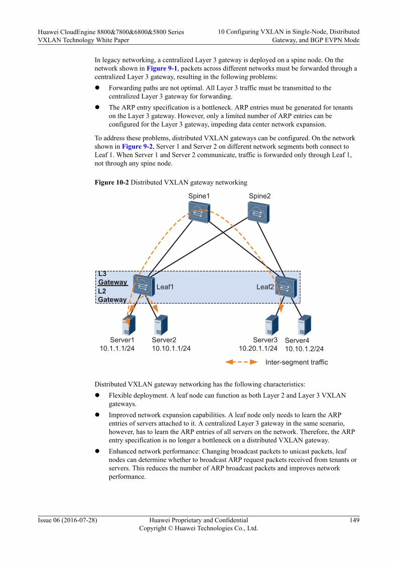
In legacy networking, a centralized Layer 3 gateway is deployed on a spine node. On thenetwork shown in Figure 9-1, packets across different networks must be forwarded through acentralized Layer 3 gateway, resulting in the following problems:l Forwarding paths are not optimal. All Layer 3 traffic must be transmitted to the
centralized Layer 3 gateway for forwarding.l The ARP entry specification is a bottleneck. ARP entries must be generated for tenants
on the Layer 3 gateway. However, only a limited number of ARP entries can beconfigured for the Layer 3 gateway, impeding data center network expansion.
To address these problems, distributed VXLAN gateways can be configured. On the networkshown in Figure 9-2, Server 1 and Server 2 on different network segments both connect toLeaf 1. When Server 1 and Server 2 communicate, traffic is forwarded only through Leaf 1,not through any spine node.
Figure 10-2 Distributed VXLAN gateway networking
Inter-segment traffic
Leaf1 Leaf2
Spine1 Spine2
L3 GatewayL2 Gateway
Server110.1.1.1/24
Server210.10.1.1/24
Server310.20.1.1/24
Server410.10.1.2/24
Distributed VXLAN gateway networking has the following characteristics:l Flexible deployment. A leaf node can function as both Layer 2 and Layer 3 VXLAN
gateways.l Improved network expansion capabilities. A leaf node only needs to learn the ARP
entries of servers attached to it. A centralized Layer 3 gateway in the same scenario,however, has to learn the ARP entries of all servers on the network. Therefore, the ARPentry specification is no longer a bottleneck on a distributed VXLAN gateway.
l Enhanced network performance: Changing broadcast packets to unicast packets, leafnodes can determine whether to broadcast ARP request packets received from tenants orservers. This reduces the number of ARP broadcast packets and improves networkperformance.
Huawei CloudEngine 8800&7800&6800&5800 SeriesVXLAN Technology White Paper
10 Configuring VXLAN in Single-Node, DistributedGateway, and BGP EVPN Mode
Issue 06 (2016-07-28) Huawei Proprietary and ConfidentialCopyright © Huawei Technologies Co., Ltd.
149
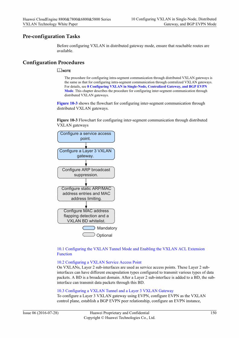
Pre-configuration Tasks
Before configuring VXLAN in distributed gateway mode, ensure that reachable routes areavailable.
Configuration ProceduresNOTE
The procedure for configuring intra-segment communication through distributed VXLAN gateways isthe same as that for configuring intra-segment communication through centralized VXLAN gateways.For details, see 8 Configuring VXLAN in Single-Node, Centralized Gateway, and BGP EVPNMode. This chapter describes the procedure for configuring inter-segment communication throughdistributed VXLAN gateways.
Figure 10-3 shows the flowchart for configuring inter-segment communication throughdistributed VXLAN gateways.
Figure 10-3 Flowchart for configuring inter-segment communication through distributedVXLAN gateways
Configure a Layer 3 VXLAN gateway.
Configure ARP broadcast suppression.
Mandatory
Optional
Configure static ARP/MAC address entries and MAC
address limiting.
Configure a service access point.
Configure MAC address flapping detection and a
VXLAN BD whitelist.
10.1 Configuring the VXLAN Tunnel Mode and Enabling the VXLAN ACL ExtensionFunction
10.2 Configuring a VXLAN Service Access PointOn VXLANs, Layer 2 sub-interfaces are used as service access points. These Layer 2 sub-interfaces can have different encapsulation types configured to transmit various types of datapackets. A BD is a broadcast domain. After a Layer 2 sub-interface is added to a BD, the sub-interface can transmit data packets through this BD.
10.3 Configuring a VXLAN Tunnel and a Layer 3 VXLAN GatewayTo configure a Layer 3 VXLAN gateway using EVPN, configure EVPN as the VXLANcontrol plane, establish a BGP EVPN peer relationship, configure an EVPN instance,
Huawei CloudEngine 8800&7800&6800&5800 SeriesVXLAN Technology White Paper
10 Configuring VXLAN in Single-Node, DistributedGateway, and BGP EVPN Mode
Issue 06 (2016-07-28) Huawei Proprietary and ConfidentialCopyright © Huawei Technologies Co., Ltd.
150
configure a VPN instance, configure ingress replication, configure the type of route to beadvertised between VXLAN gateways,and bind the VPN instance to a Layer 3 VXLANgateway.
10.4 (Optional) Configuring ARP Broadcast SuppressionWhen tenants communicate with each other for the first time, they send ARP requests. TheseARP requests are broadcast on Layer 2 networks and may cause a broadcast storm. To preventthis problem, ARP broadcast suppression can be enabled on Layer 2 VXLAN gateways.
10.5 (Optional) Disabling a VBDIF Interface from Sending ARP Miss Messages
10.6 (Optional) Configuring Static ARP/MAC Address Entries and MAC Address LimitingStatic ARP entries or MAC address entries can be configured for traffic forwarding, andMAC address limiting can be configured to improve VXLAN security.
10.7 (Optional) Configuring a VXLAN BD Whitelist for MAC Address Flapping DetectionIn specific VXLAN applications, when a device connects to a load balancing server equippedwith two network interface cards, the server's MAC address may be learned by two interfaceson the device. This is a normal situation where MAC address flapping detection is not needed.In this case, configure a VXLAN BD whitelist for MAC address flapping detection.
10.8 (Optional) Configuring IP Address Conflict Detection ParametersOn VXLANs, IP address conflicts of terminal users will prevent these users from goingonline. Therefore, IP address conflicts must be detected.
10.9 (Optional) Optimizing Load Balancing on the VXLAN Network
10.10 Checking the ConfigurationsAfter configuring VXLAN in distributed gateway mode using BGP EVPN, check theconfigurations, and you can find that VXLAN tunnels are dynamically established and are inthe Up state.
Huawei CloudEngine 8800&7800&6800&5800 SeriesVXLAN Technology White Paper
10 Configuring VXLAN in Single-Node, DistributedGateway, and BGP EVPN Mode
Issue 06 (2016-07-28) Huawei Proprietary and ConfidentialCopyright © Huawei Technologies Co., Ltd.
151
10.1 Configuring the VXLAN Tunnel Mode and Enablingthe VXLAN ACL Extension Function
Contextl Configuring a tunnel mode: You need to set the tunnel mode to VXLAN when
configuring the VXLAN feature; otherwise, the configurations do not take effect.l Enabling the VXLAN ACL extension function: By default, the VXLAN ACL extension
function is disabled on the device. If you configure other ACL resource-consumingservices, such as MQC, simplified ACL, traffic policing, and BD traffic statisticscollection, on the device deployed with VXLAN services, there is high probability thatthe other services fail to be configured. You can enable the VXLAN ACL extensionfunction to lower the configuration failure probability.
To ensure normal forwarding of VXLAN packets, the VXLAN tunnel mode must have beenconfigured and the VXLAN ACL extension function must have been enabled on Layer 2 andLayer 3 VXLAN gateways.
NOTE
You can configure the VXLAN tunnel mode and enable the VXLAN ACL extension function only onthe CE6870EI.
Procedure
Step 1 Run:system-view
The system view is displayed.
Step 2 Run:ip tunnel mode vxlan
The tunnel mode is set to VXLAN.
By default, the tunnel mode is VXLAN.
Step 3 Run:assign forward nvo3 acl extend enable
The VXLAN ACL extension function is enabled.
By default, the VXLAN ACL extension function is disabled.
Step 4 Run:commit
The configuration is committed.
----End
Follow-up ProcedureAfter configuring the VXLAN tunnel mode and enabling the VXLAN ACL extensionfunction, you need to save the configuration and restart the switch to make the configurationtake effect.
Huawei CloudEngine 8800&7800&6800&5800 SeriesVXLAN Technology White Paper
10 Configuring VXLAN in Single-Node, DistributedGateway, and BGP EVPN Mode
Issue 06 (2016-07-28) Huawei Proprietary and ConfidentialCopyright © Huawei Technologies Co., Ltd.
152
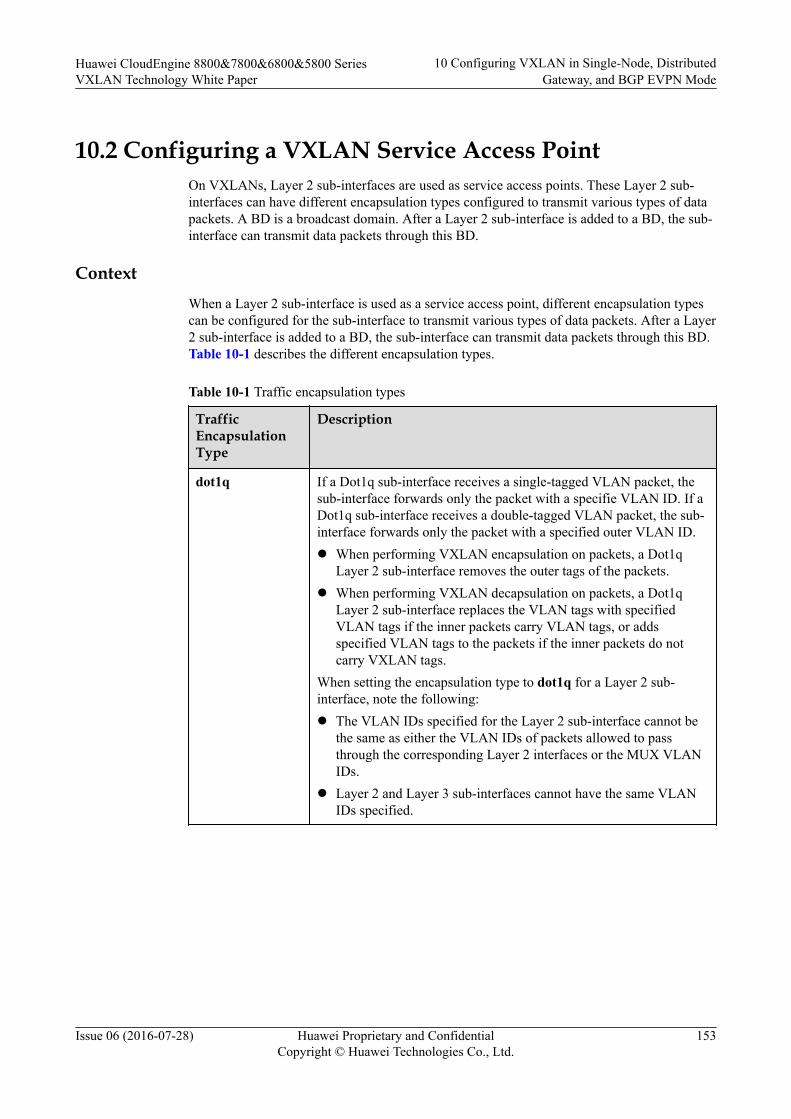
10.2 Configuring a VXLAN Service Access PointOn VXLANs, Layer 2 sub-interfaces are used as service access points. These Layer 2 sub-interfaces can have different encapsulation types configured to transmit various types of datapackets. A BD is a broadcast domain. After a Layer 2 sub-interface is added to a BD, the sub-interface can transmit data packets through this BD.
ContextWhen a Layer 2 sub-interface is used as a service access point, different encapsulation typescan be configured for the sub-interface to transmit various types of data packets. After a Layer2 sub-interface is added to a BD, the sub-interface can transmit data packets through this BD.Table 10-1 describes the different encapsulation types.
Table 10-1 Traffic encapsulation types
TrafficEncapsulationType
Description
dot1q If a Dot1q sub-interface receives a single-tagged VLAN packet, thesub-interface forwards only the packet with a specifie VLAN ID. If aDot1q sub-interface receives a double-tagged VLAN packet, the sub-interface forwards only the packet with a specified outer VLAN ID.l When performing VXLAN encapsulation on packets, a Dot1q
Layer 2 sub-interface removes the outer tags of the packets.l When performing VXLAN decapsulation on packets, a Dot1q
Layer 2 sub-interface replaces the VLAN tags with specifiedVLAN tags if the inner packets carry VLAN tags, or addsspecified VLAN tags to the packets if the inner packets do notcarry VXLAN tags.
When setting the encapsulation type to dot1q for a Layer 2 sub-interface, note the following:l The VLAN IDs specified for the Layer 2 sub-interface cannot be
the same as either the VLAN IDs of packets allowed to passthrough the corresponding Layer 2 interfaces or the MUX VLANIDs.
l Layer 2 and Layer 3 sub-interfaces cannot have the same VLANIDs specified.
Huawei CloudEngine 8800&7800&6800&5800 SeriesVXLAN Technology White Paper
10 Configuring VXLAN in Single-Node, DistributedGateway, and BGP EVPN Mode
Issue 06 (2016-07-28) Huawei Proprietary and ConfidentialCopyright © Huawei Technologies Co., Ltd.
153
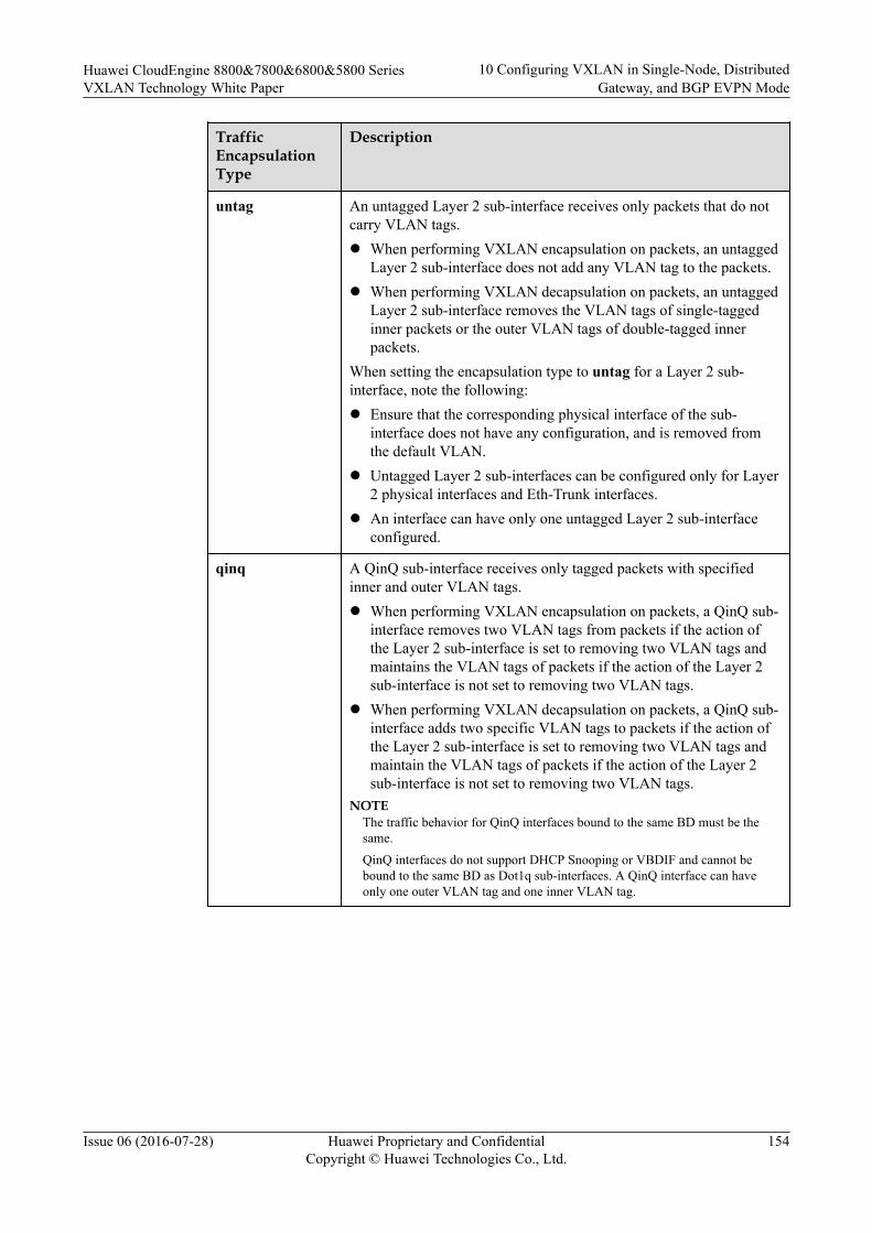
TrafficEncapsulationType
Description
untag An untagged Layer 2 sub-interface receives only packets that do notcarry VLAN tags.l When performing VXLAN encapsulation on packets, an untagged
Layer 2 sub-interface does not add any VLAN tag to the packets.l When performing VXLAN decapsulation on packets, an untagged
Layer 2 sub-interface removes the VLAN tags of single-taggedinner packets or the outer VLAN tags of double-tagged innerpackets.
When setting the encapsulation type to untag for a Layer 2 sub-interface, note the following:l Ensure that the corresponding physical interface of the sub-
interface does not have any configuration, and is removed fromthe default VLAN.
l Untagged Layer 2 sub-interfaces can be configured only for Layer2 physical interfaces and Eth-Trunk interfaces.
l An interface can have only one untagged Layer 2 sub-interfaceconfigured.
qinq A QinQ sub-interface receives only tagged packets with specifiedinner and outer VLAN tags.l When performing VXLAN encapsulation on packets, a QinQ sub-
interface removes two VLAN tags from packets if the action ofthe Layer 2 sub-interface is set to removing two VLAN tags andmaintains the VLAN tags of packets if the action of the Layer 2sub-interface is not set to removing two VLAN tags.
l When performing VXLAN decapsulation on packets, a QinQ sub-interface adds two specific VLAN tags to packets if the action ofthe Layer 2 sub-interface is set to removing two VLAN tags andmaintain the VLAN tags of packets if the action of the Layer 2sub-interface is not set to removing two VLAN tags.
NOTEThe traffic behavior for QinQ interfaces bound to the same BD must be thesame.
QinQ interfaces do not support DHCP Snooping or VBDIF and cannot bebound to the same BD as Dot1q sub-interfaces. A QinQ interface can haveonly one outer VLAN tag and one inner VLAN tag.
Huawei CloudEngine 8800&7800&6800&5800 SeriesVXLAN Technology White Paper
10 Configuring VXLAN in Single-Node, DistributedGateway, and BGP EVPN Mode
Issue 06 (2016-07-28) Huawei Proprietary and ConfidentialCopyright © Huawei Technologies Co., Ltd.
154

TrafficEncapsulationType
Description
default A default Layer 2 sub-interface receives all packets, irrespective ofwhether the packets carry VLAN tags.When performing VXLAN encapsulation and decapsulation onpackets, a default Layer 2 sub-interface does not process VLAN tagsof the packets.When setting the encapsulation type to default for a Layer 2 sub-interface, note the following:l Ensure that the interface for the Layer 2 sub-interface is not added
to any VLAN.l Default Layer 2 sub-interfaces can be configured only for Layer 2
physical interfaces and Eth-Trunk interfaces.l If a default Layer 2 sub-interface is created for an interface, the
interface cannot have other types of Layer 2 sub-interfacesconfigured.
NOTEWhen a sub-interface that is configured with dot1q and QinQ receives double-tagged VLAN packets, theQinQ sub-interface preferentially processes the packets. For example, if a dot1q and QinQ sub-interfacecarries the VLAN ID of 10 for dot1q and outer VLAN ID of 10 and inner VLAN ID of 20 for QinQ andreceives a packet with the outer VLAN ID of 10 and inner VLAN ID of 20, the QinQ sub-interfacepreferentially processes the packet. If a dot1q and QinQ sub-interface carries the VLAN ID of 10 fordot1q and outer VLAN ID of 10 and inner VLAN ID of 20 for QinQ and receives a packet with theouter VLAN ID of 10 and inner VLAN ID of non-20, the dot1q sub-interface preferentially processesthe packet.
Procedure
Step 1 Run:system-view
The system view is displayed.
Step 2 Run:bridge-domain bd-id
A BD is created, and the BD view is displayed.
By default, no BD is created.
Step 3 (Optional) Run:description description
A description is configured for the BD.
By default, no description is configured for a BD.
Step 4 Run:quit
Return to the system view.
Huawei CloudEngine 8800&7800&6800&5800 SeriesVXLAN Technology White Paper
10 Configuring VXLAN in Single-Node, DistributedGateway, and BGP EVPN Mode
Issue 06 (2016-07-28) Huawei Proprietary and ConfidentialCopyright © Huawei Technologies Co., Ltd.
155
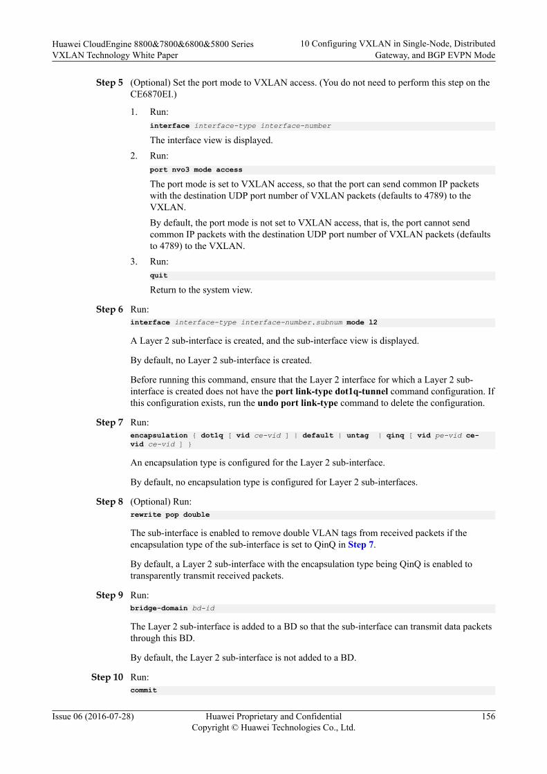
Step 5 (Optional) Set the port mode to VXLAN access. (You do not need to perform this step on theCE6870EI.)
1. Run:interface interface-type interface-number
The interface view is displayed.2. Run:
port nvo3 mode access
The port mode is set to VXLAN access, so that the port can send common IP packetswith the destination UDP port number of VXLAN packets (defaults to 4789) to theVXLAN.By default, the port mode is not set to VXLAN access, that is, the port cannot sendcommon IP packets with the destination UDP port number of VXLAN packets (defaultsto 4789) to the VXLAN.
3. Run:quit
Return to the system view.
Step 6 Run:interface interface-type interface-number.subnum mode l2
A Layer 2 sub-interface is created, and the sub-interface view is displayed.
By default, no Layer 2 sub-interface is created.
Before running this command, ensure that the Layer 2 interface for which a Layer 2 sub-interface is created does not have the port link-type dot1q-tunnel command configuration. Ifthis configuration exists, run the undo port link-type command to delete the configuration.
Step 7 Run:encapsulation { dot1q [ vid ce-vid ] | default | untag | qinq [ vid pe-vid ce-vid ce-vid ] }
An encapsulation type is configured for the Layer 2 sub-interface.
By default, no encapsulation type is configured for Layer 2 sub-interfaces.
Step 8 (Optional) Run:rewrite pop double
The sub-interface is enabled to remove double VLAN tags from received packets if theencapsulation type of the sub-interface is set to QinQ in Step 7.
By default, a Layer 2 sub-interface with the encapsulation type being QinQ is enabled totransparently transmit received packets.
Step 9 Run:bridge-domain bd-id
The Layer 2 sub-interface is added to a BD so that the sub-interface can transmit data packetsthrough this BD.
By default, the Layer 2 sub-interface is not added to a BD.
Step 10 Run:commit
Huawei CloudEngine 8800&7800&6800&5800 SeriesVXLAN Technology White Paper
10 Configuring VXLAN in Single-Node, DistributedGateway, and BGP EVPN Mode
Issue 06 (2016-07-28) Huawei Proprietary and ConfidentialCopyright © Huawei Technologies Co., Ltd.
156
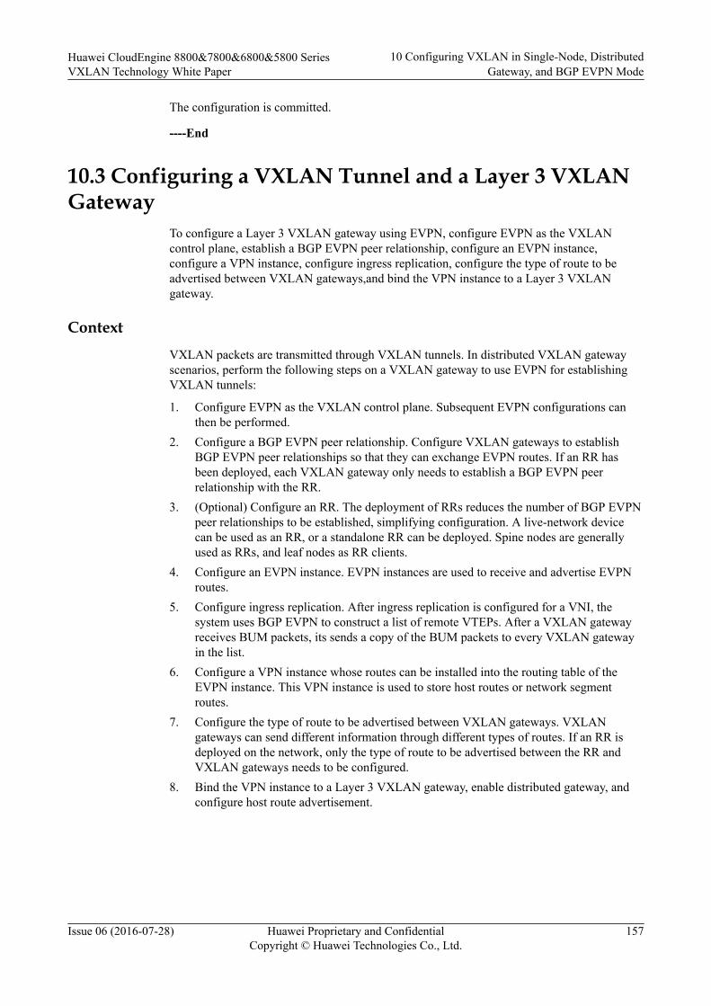
The configuration is committed.
----End
10.3 Configuring a VXLAN Tunnel and a Layer 3 VXLANGateway
To configure a Layer 3 VXLAN gateway using EVPN, configure EVPN as the VXLANcontrol plane, establish a BGP EVPN peer relationship, configure an EVPN instance,configure a VPN instance, configure ingress replication, configure the type of route to beadvertised between VXLAN gateways,and bind the VPN instance to a Layer 3 VXLANgateway.
ContextVXLAN packets are transmitted through VXLAN tunnels. In distributed VXLAN gatewayscenarios, perform the following steps on a VXLAN gateway to use EVPN for establishingVXLAN tunnels:
1. Configure EVPN as the VXLAN control plane. Subsequent EVPN configurations canthen be performed.
2. Configure a BGP EVPN peer relationship. Configure VXLAN gateways to establishBGP EVPN peer relationships so that they can exchange EVPN routes. If an RR hasbeen deployed, each VXLAN gateway only needs to establish a BGP EVPN peerrelationship with the RR.
3. (Optional) Configure an RR. The deployment of RRs reduces the number of BGP EVPNpeer relationships to be established, simplifying configuration. A live-network devicecan be used as an RR, or a standalone RR can be deployed. Spine nodes are generallyused as RRs, and leaf nodes as RR clients.
4. Configure an EVPN instance. EVPN instances are used to receive and advertise EVPNroutes.
5. Configure ingress replication. After ingress replication is configured for a VNI, thesystem uses BGP EVPN to construct a list of remote VTEPs. After a VXLAN gatewayreceives BUM packets, its sends a copy of the BUM packets to every VXLAN gatewayin the list.
6. Configure a VPN instance whose routes can be installed into the routing table of theEVPN instance. This VPN instance is used to store host routes or network segmentroutes.
7. Configure the type of route to be advertised between VXLAN gateways. VXLANgateways can send different information through different types of routes. If an RR isdeployed on the network, only the type of route to be advertised between the RR andVXLAN gateways needs to be configured.
8. Bind the VPN instance to a Layer 3 VXLAN gateway, enable distributed gateway, andconfigure host route advertisement.
Huawei CloudEngine 8800&7800&6800&5800 SeriesVXLAN Technology White Paper
10 Configuring VXLAN in Single-Node, DistributedGateway, and BGP EVPN Mode
Issue 06 (2016-07-28) Huawei Proprietary and ConfidentialCopyright © Huawei Technologies Co., Ltd.
157

NOTE
If tenants on the same network segment connect to different Layer 3 VXLAN gateways, the Layer 3VXLAN gateways must have the same IP address and MAC address configured. When tenants aremoved to a different location, the tenants can retain Layer 3 gateway configurations, reducingmaintenance workload.
BUM packet forwarding is implemented only using ingress replication. To establish a VXLAN tunnelbetween a Huawei device and a non-Huawei device, ensure that the non-Huawei device also has ingressreplication configured. Otherwise, communication fails.
Procedure
Step 1 Configure EVPN as the VXLAN control plane.1. Run:
system-view
The system view is displayed.2. Run:
evpn-overlay enable
EVPN is configured as the VXLAN control plane.
By default, EVPN is not configured as the VXLAN control plane.3. Run:
commit
The configuration is committed.
Step 2 Configure a BGP EVPN peer relationship. If an RR has been deployed, each VXLANgateway only needs to establish a BGP EVPN peer relationship with the RR. If the spine nodeand gateway reside in different ASs, the gateway must establish an EBGP EVPN peerrelationship with the spine node.1. Run:
bgp as-number [ instance instance-name ]
BGP is enabled, and the BGP or BGP multi-instance view is displayed.
By default, the BGP is disabled. If an RR has been deployed, each VXLAN gatewayonly needs to establish a BGP EVPN peer relationship with the RR.
2. (Optional) Run:router-id ipv4-address
A router ID is set.
By default, no BGP Router ID is configured, and the Router ID configured for the routemanagement module through the router id command is used.
3. Run:peer ipv4-address as-number as-number
The peer device is configured as a BGP peer.
By default, no BGP peer is configured, and no AS number is specified for a peer or peergroup.
4. (Optional) Run:peer ipv4-address connect-interface interface-type interface-number [ ipv4-source-address ]
Huawei CloudEngine 8800&7800&6800&5800 SeriesVXLAN Technology White Paper
10 Configuring VXLAN in Single-Node, DistributedGateway, and BGP EVPN Mode
Issue 06 (2016-07-28) Huawei Proprietary and ConfidentialCopyright © Huawei Technologies Co., Ltd.
158

A source interface and a source address are specified to set up a TCP connection with theBGP peer.
By default, the outbound interface of a BGP packet serves as the source interface of aBGP packet.
NOTE
When loopback interfaces are used to establish a BGP connection, running the peer connect-interface command on both ends is recommended to ensure the connectivity. If this command isrun on only one end, the BGP connection may fail to be established.
5. (Optional) Run:peer ipv4-address ebgp-max-hop [ hop-count ]
The maximum number of hops is set for an EBGP EVPN connection.
The default value of hop-count is 255.
In most cases, a directly connected physical link must be available between EBGPEVPN peers. If you want to establish EBGP EVPN peer relationships between indirectlyconnected peers, run the peer ebgp-max-hop command. The command also canconfigure the maximum number of hops for an EBGP EVPN connection.
NOTE
When the IP address of loopback interface to establish an EBGP EVPN peer relationship, run thepeer ebgp-max-hop (of which the value of hop-count is not less than 2) command. Otherwise, thepeer relationship fails to be established.
6. Run:l2vpn-family evpn
The BGP-EVPN address family view or BGP multi-instance EVPN view is displayed.
By default, the BGP-EVPN address family or BGP multi-instance EVPN view isdisabled.
7. Run:peer { ipv4-address | group-name } enable
The device is enabled to exchange EVPN routes with a specified peer or peer group.
By default, only the peer in the BGP IPv4 unicast address family view is automaticallyenabled.
8. (Optional) Run:peer { group-name | ipv4-address } route-policy route-policy-name { import | export }
A routing policy is specified for routes received from or to be advertised to a BGP EVPNpeer or peer group.
After the routing policy is applied, the routes received from or to be advertised to aspecified BGP EVPN peer or peer group will be filtered, ensuring that only desiredroutes are imported or advertised. This configuration helps manage routes and reducerequired routing entries and system resources.
9. (Optional) Run:peer { ipv4-address | group-name } next-hop-invariable
The device is prevented from changing the next hop address of a route when advertisingthe route to an EBGP peer. If the spine node and gateway have established an EBGP
Huawei CloudEngine 8800&7800&6800&5800 SeriesVXLAN Technology White Paper
10 Configuring VXLAN in Single-Node, DistributedGateway, and BGP EVPN Mode
Issue 06 (2016-07-28) Huawei Proprietary and ConfidentialCopyright © Huawei Technologies Co., Ltd.
159
EVPN peer relationship, run the peer next-hop-invariable command to ensure that thenext hops of routes received by the gateway point to other gateways.
By default, a BGP EVPN speaker changes the next hops of routes to the interface that ituses to establish EBGP EVPN peer relationships before advertising these routes toEBGP EVPN peers.
10. (Optional) Run:peer { group-name | ipv4-address } mac-limit number [ percentage ] [ alert-only | idle-forever | idle-timeout times ]
The maximum number of MAC advertisement routes that can be received from eachpeer is configured.
If an EVPN instance may import many invalid MAC advertisement routes from peersand these routes occupy a large proportion of the total MAC advertisement routes. If thereceived MAC advertisement routes exceed the specified maximum number, the systemdisplays an alarm, instructing users to check the validity of the MAC advertisementroutes received in the EVPN instance.
11. Run:quit
Exit from the BGP-EVPN address family view or BGP multi-instance EVPN view.12. Run:
quit
Exit from the BGP or BGP multi-instance view.13. Run:
commit
The configuration is committed.
Step 3 (Optional) Configure an RR. If an RR is configured, each VXLAN gateway only needs toestablish a BGP EVPN peer relationship with the RR, reducing the number of BGP EVPNpeer relationships to be established and simplifying configuration.1. Run:
bgp as-number [ instance instance-name ]
The BGP or BGP multi-instance view is displayed.2. Run:
l2vpn-family evpn
The BGP-EVPN address family view or BGP multi-instance EVPN view is displayed.3. Run:
peer { ipv4-address | group-name } reflect-client
The device is configured as an RR and an RR client is specified.
By default, the route reflector and its client are not configured.4. Run:
undo policy vpn-target
The function to filter received EVPN routes based on VPN targets is disabled. If you donot perform this step, the RR will fail to receive and reflect the routes sent by clients.
5. Run:quit
Huawei CloudEngine 8800&7800&6800&5800 SeriesVXLAN Technology White Paper
10 Configuring VXLAN in Single-Node, DistributedGateway, and BGP EVPN Mode
Issue 06 (2016-07-28) Huawei Proprietary and ConfidentialCopyright © Huawei Technologies Co., Ltd.
160
Exit from the BGP-EVPN address family view or BGP multi-instance EVPN view.6. Run:
quit
Exit from the BGP or BGP multi-instance view.7. Run:
commit
The configuration is committed.
Step 4 Configure an EVPN instance.1. Run:
bridge-domain bd-id
The BD view is displayed.
By default, no bridge domain is created.2. Run:
vxlan vni vni-id
A VNI is created and mapped to the BD.
By default, no VNI is created.3. Run:
evpn
An EVPN instance is created.
By default, no EVPN instance is created for VXLANs.4. Run:
route-distinguisher { route-distinguisher | auto }
An RD is configured for the EVPN instance. The two ends of a VXLAN tunnel canshare an RD or use different RDs.
By default, no RD is configured for BD EVPN instances.5. Run:
vpn-target { vpn-target &<1-8> | auto } [ both | export-extcommunity | import-extcommunity ]
VPN targets are configured for the EVPN instance. The export VPN target of the localend must be the same as the import VPN target of the remote end, and the import VPNtarget of the local end must be the same as the export VPN target of the remote end.
By default, no VPN target is configured for BD EVPN instances.6. (Optional) Run:
import route-policy policy-name
The current EVPN instance is associated with an import routing policy.
By default, an EVPN instance matches the export VPN targets of received routes againstits import VPN targets to determine whether to import these routes. To control routeimport more precisely, perform this step to associate the EVPN instance with an importrouting policy and set attributes for eligible routes.
7. (Optional) Run:export route-policy policy-name
Huawei CloudEngine 8800&7800&6800&5800 SeriesVXLAN Technology White Paper
10 Configuring VXLAN in Single-Node, DistributedGateway, and BGP EVPN Mode
Issue 06 (2016-07-28) Huawei Proprietary and ConfidentialCopyright © Huawei Technologies Co., Ltd.
161

The current EVPN instance is associated with an export routing policy.
By default, an EVPN instance adds all VPN targets in the export VPN target list toEVPN routes to be advertised to its peers. To control route export more precisely,perform this step to associate the EVPN instance with an export routing policy and setattributes for eligible routes.
8. Run:quit
The EVPN instance view is exited.9. Run:
quit
Return to the system view.10. Run:
commit
The configuration is committed.
Step 5 Configure an ingress replication list.1. Run:
interface nve nve-number
An NVE interface is created, and the NVE interface view is displayed.2. Run:
source ip-address
An IP address is configured for the source VTEP.
By default, no IP address is configured for any source VTEP.3. Run:
vni vni-id head-end peer-list protocol bgp
An ingress replication list is configured.
By default, no ingress replication list is configured for any VNI.
NOTE
BUM packet forwarding is implemented only using ingress replication. To establish a VXLANtunnel between a Huawei device and a non-Huawei device, ensure that the non-Huawei devicealso has ingress replication configured. Otherwise, communication fails.
4. Run:quit
Return to the system view.5. Run:
commit
The configuration is committed.
Step 6 (Optional) Configure a MAC address for an NVE interface.
When BGP EVPN is deployed between distributed VXLAN gateways, you need to configurethe same VTEP MAC address for the two devices that provide dual-active VXLAN access. Inthis way, gateways on the VXLAN network can forward traffic properly.
Huawei CloudEngine 8800&7800&6800&5800 SeriesVXLAN Technology White Paper
10 Configuring VXLAN in Single-Node, DistributedGateway, and BGP EVPN Mode
Issue 06 (2016-07-28) Huawei Proprietary and ConfidentialCopyright © Huawei Technologies Co., Ltd.
162

1. Run:interface nve nve-number
The NVE interface view is displayed.2. Run:
mac-address mac-address
A MAC address is configured for the NVE interface.
By default, the MAC address of an NVE interface is the system MAC address.3. Run:
quit
Return to the system view.4. Run:
commit
The configuration is committed.
Step 7 Configure a VPN instance whose routes can be installed into the routing table of the EVPNinstance.1. Run:
ip vpn-instance vpn-instance-name
A VPN instance is created, and the VPN instance view is displayed.
By default, no VPN instance is created.2. Run:
vxlan vni vni-id
A VNI is created and mapped to the VPN instance.
By default, a VNI is not bound to any VPN instance.3. Run:
ipv4-family
The IPv4 address family is enabled for the VPN instance, and the VPN instance IPv4address family view is displayed.
By default, the IPv4 address family is disabled for a VPN instance.4. Run:
route-distinguisher route-distinguisher
An RD is configured for the VPN instance IPv4 address family.
By default, no RD is configured for the VPN instance IPv4 address family.5. Run:
vpn-target vpn-target &<1-8> [ both | export-extcommunity | import-extcommunity ]
VPN targets are configured for the VPN instance IPv4 address family.
By default, no VPN target is configured for a VPN instance IPv4 address family.
A VPN target is the extended community attribute of BGP. It controls reception andadvertisement of VPN routes. A maximum of eight VPN targets can be configured eachtime the vpn-target command is run. To configure more VPN targets for the VPNinstance IPv4 address family, run the vpn-target command several times.
Huawei CloudEngine 8800&7800&6800&5800 SeriesVXLAN Technology White Paper
10 Configuring VXLAN in Single-Node, DistributedGateway, and BGP EVPN Mode
Issue 06 (2016-07-28) Huawei Proprietary and ConfidentialCopyright © Huawei Technologies Co., Ltd.
163

6. Run:vpn-target vpn-target &<1-8> [ both | export-extcommunity | import-extcommunity ] evpn
VPN targets are configured for the VPN instance IPv4 address family for routeinstallation into the EVPN instance. vpn-target specified here must be the same as the RTconfigured for the EVPN instance in the BD view. This implementation ensures thatroutes in the VPN instance can be installed into the routing table of the specified EVPNinstance.
7. (Optional) Run:import route-policy policy-name evpn
The VPN instance IPv4 address family of the current VPN instance is associated with animport routing policy to filter routes imported from the EVPN instance.
By default, the VPN instance IPv4 address family of a VPN instance matches the exportVPN targets of received routes against its import VPN targets to determine whether toimport these routes. To control route import more precisely, perform this step toassociate the VPN IPv4 address family with an import routing policy and set attributesfor eligible routes.
8. (Optional) Run:export route-policy policy-name evpn
The VPN instance IPv4 address family of the current VPN instance is associated with anexport routing policy to filter routes to be advertised to the EVPN instance.
By default, the VPN IPv4 address family adds all VPN targets in the export VPN targetlist to routes to be advertised to the EVPN instance. To control route export moreprecisely, perform this step to associate the VPN IPv4 address family with an exportrouting policy and set attributes for eligible routes.
9. Run:quit
The VPN instance IPv4 address family view is exited.10. Run:
quit
The VPN instance view is exited.11. Run:
commit
The configuration is committed.
Step 8 Configure the type of route to be advertised between VXLAN gateways. If an RR is deployedon the network, only the type of route to be advertised between the RR and VXLAN gatewaysneeds to be configured.
VXLAN gateways can advertise the forwarding types of routes. Table 10-2 lists the scenarioand deployment for each type of route. By default, the type of route to be advertised is notspecified.
Huawei CloudEngine 8800&7800&6800&5800 SeriesVXLAN Technology White Paper
10 Configuring VXLAN in Single-Node, DistributedGateway, and BGP EVPN Mode
Issue 06 (2016-07-28) Huawei Proprietary and ConfidentialCopyright © Huawei Technologies Co., Ltd.
164

Table 10-2 Configuring the type of route to be advertised between VXLAN gateways
Route Type Usage Scenario Configuration Procedure
Configure IRB routeadvertisement.
In scenarios where ARPbroadcast suppression isneeded, configure IRB routeadvertisement beforerunning the arp broadcast-suppress enable command.VXLAN gateways can alsouse IRB routes to advertisehost routes.NOTE
After configuring IRB routeadvertisement, you must runthe arp collect host enablecommand for host routeadvertisement.
1. Run the bgp as-number[ instance instance-name ] command to enterthe BGP or BGP multi-instance view.
2. Run the l2vpn-familyevpn command to enterthe BGP-EVPN addressfamily view or BGPmulti-instance EVPNview.
3. Run the peer { ipv4-address | group-name }advertise irb commandto configure IRB routeadvertisement.
4. Run the quit commandto exit the BGP-EVPNaddress family view orBGP multi-instanceEVPN view.
5. Run the quit commandto exit the BGP or BGPmulti-instance view.
6. Run the commitcommand to commit theconfiguration.
Huawei CloudEngine 8800&7800&6800&5800 SeriesVXLAN Technology White Paper
10 Configuring VXLAN in Single-Node, DistributedGateway, and BGP EVPN Mode
Issue 06 (2016-07-28) Huawei Proprietary and ConfidentialCopyright © Huawei Technologies Co., Ltd.
165

Route Type Usage Scenario Configuration Procedure
Configure IP prefix routeadvertisement.
Though IP prefix routeadvertisement cannotimplement ARP broadcastsuppression, it allowsadvertisement of networksegment routes for hostroutes between VXLANgateways. If a large numberof specific host routes areavailable, you can configureIP prefix routeadvertisement so thatVXLAN gateways do nothave to store all theseroutes.NOTE
l A VXLAN gateway canadvertise network segmentroutes only if the networksegments attached to thegateway are uniquenetwork-wide.
l After configuring IP prefixroute advertisement, youmust run the arp direct-route enable command forhost route advertisement.Then, host migration willbe affected. To avoid thisproblem, configure IRBroute advertisement.
1. Run the bgp as-number[ instance instance-name ] command to enterthe BGP or BGP multi-instance view.
2. Run the ipv4-familyvpn-instance vpn-instance-name commandto enter the BGP-VPNinstance IPv4 addressfamily view.
3. Run the advertise l2vpnevpn command toconfigure IP prefix routeadvertisement.
4. Run the quit commandto exit the BGP-VPNinstance IPv4 addressfamily view.
5. Run the quit commandto exit the BGP or BGPmulti-instance view.
6. Run the commitcommand to commit theconfiguration.
Step 9 Configure a service loopback interface for the Layer 3 gateway. (You do not need to performthis step on the CE6855HI, CE6870EI, and CE7855EI.)1. Run:
interface eth-trunk trunk-id
The Eth-Trunk interface view is displayed.2. Run:
service type tunnel
Service loopback is enabled on the Eth-Trunk to loop back service packets of theVXLAN Layer 3 gateway.
NOTE
– One service loopback interface takes effect for a maximum of 2000 VBDIF interfaces.
– After you run the service type tunnel command on an Eth-Trunk, the Eth-Trunk and itsphysical member interfaces can only be used for the VXLAN Layer 3 gateway and cannot beconfigured with other services.
3. Run:trunkport interface-type { interface-number1 [ to interface-number2 ] }
Huawei CloudEngine 8800&7800&6800&5800 SeriesVXLAN Technology White Paper
10 Configuring VXLAN in Single-Node, DistributedGateway, and BGP EVPN Mode
Issue 06 (2016-07-28) Huawei Proprietary and ConfidentialCopyright © Huawei Technologies Co., Ltd.
166
Member interfaces are added to the Eth-Trunk.
NOTE
– The member interfaces must be idle and do not transmit services.
– Ensure that the Eth-Trunk bandwidth is at least twice the bandwidth required for transmittingVXLAN Layer 3 gateway traffic. For example, if traffic is sent from users to the gatewayacross the VXLAN network at a rate of 10 Gbit/s, add two 10GE interface to the Eth-Trunkthat you want to use as the service loopback interface.
4. Run:quit
Return to the system view.
Step 10 Bind the VPN instance to a Layer 3 gateway, enable distributed gateway, and configure hostroute advertisement.1. Run:
interface vbdif bd-id
A VBDIF interface is created, and the VBDIF interface view is displayed.
By default, no VBDIF interface is created.2. Run:
ip binding vpn-instance vpn-instance-name
A VPN instance is bound to the VBDIF interface.3. Run:
ip address ip-address { mask | mask-length } [ sub ]
An IP address is configured for the VBDIF interface to implement Layer 3 interworking.
By default, no IP address is configured for interfaces.4. (Optional) Run:
mac-address mac-address
A MAC address is configured for the VBDIF interface.
By default, the MAC address of a VBDIF interface is the system MAC address.5. Run:
arp distribute-gateway enable
Distributed gateway is enabled.
By default, distributed gateway is disabled.
NOTE
After distributed gateway is enabled on a Layer 3 gateway, the Layer 3 gateway discards network-side ARP messages and learns only user-side ARP messages.
6. Perform either of the following steps to configure host route advertisement:– If VXLAN gateways advertise IRB routes to each other, run the arp collect host
enable command for host route advertisement.– If VXLAN gateways advertise IP prefix routes to each other, run the arp direct-
route enable [ route-policy route-policy-name ] command for host routeadvertisement.
7. Run:
Huawei CloudEngine 8800&7800&6800&5800 SeriesVXLAN Technology White Paper
10 Configuring VXLAN in Single-Node, DistributedGateway, and BGP EVPN Mode
Issue 06 (2016-07-28) Huawei Proprietary and ConfidentialCopyright © Huawei Technologies Co., Ltd.
167
quit
Return to the system view.8. Run:
commit
The configuration is committed.
----End
10.4 (Optional) Configuring ARP Broadcast SuppressionWhen tenants communicate with each other for the first time, they send ARP requests. TheseARP requests are broadcast on Layer 2 networks and may cause a broadcast storm. To preventthis problem, ARP broadcast suppression can be enabled on Layer 2 VXLAN gateways.
Context
After you enable ARP broadcast suppression on a Layer 2 VXLAN gateway, configureBorder Gateway Protocol Ethernet Virtual Private Network (BGP EVPN) on Layer 2 andLayer 3 VXLAN gateways to allow ARP broadcast suppression to take effect. BGP EVPNcan then generate host information based on learned ARP entries and advertise the hostinformation to Layer 2 VXLAN gateways. After the Layer 2 VXLAN gateways receive ARPbroadcast packets, they convert the ARP broadcast packets into unicast packets based on thelearned host information before forwarding the packets out. This decreases the number ofbroadcast packets in a BD, improving network performance.
Configuring BGP RRs is recommended to simplify BGP configuration. Layer 3 VXLANgateways are generally used as RRs, and Layer 2 VXLAN gateways as RR clients.
Procedure
Step 1 Configure BGP EVPN on Layer 2 and Layer 3 VXLAN gateways to advertise hostinformation learned by Layer 2 VXLAN gateways.
1. Run:system-view
The system view is displayed.2. Run:
bgp as-number [ instance instance-name ]
The BGP or BGP multi-instance view is displayed.3. Run:
l2vpn-family evpn
The BGP-EVPN address family view or BGP multi-instance EVPN view is displayed.By default, the BGP-EVPN address family or BGP multi-instance EVPN view isdisabled.
4. Configure advertisement of ARP or IRB routes to implement ARP broadcastsuppression. The following two configurations cannot coexist.– To configure ARP route advertisement, run the peer { ipv4-address | group-name }
advertise arp command.
Huawei CloudEngine 8800&7800&6800&5800 SeriesVXLAN Technology White Paper
10 Configuring VXLAN in Single-Node, DistributedGateway, and BGP EVPN Mode
Issue 06 (2016-07-28) Huawei Proprietary and ConfidentialCopyright © Huawei Technologies Co., Ltd.
168

– To configure IRB route advertisement, run the peer { ipv4-address | group-name }advertise irb command.
5. Run:commitThe configuration is committed.
Step 2 Enable BGP EVPN on a Layer 3 VXLAN gateway to collect host information.
1. Run:system-viewThe system view is displayed.
2. Run:interface vbdif bd-idThe VBDIF interface view is displayed.
3. Run:arp collect host enableBGP EVPN is enabled to collect host information.By default, BGP EVPN is disabled from collecting host information.
4. Run:commitThe configuration is committed.
Step 3 Enable ARP broadcast suppression on a Layer 2 VXLAN gateway.
1. Run:system-viewThe system view is displayed.
2. Run:bridge-domain bd-idThe BD view is displayed.
3. Run:arp broadcast-suppress enableARP broadcast suppression is enabled.By default, ARP broadcast suppression is disabled.
4. Run:commitThe configuration is committed.
----End
10.5 (Optional) Disabling a VBDIF Interface from SendingARP Miss Messages
ContextWhen the device wants to communicate with another device in the same network segment, itqueries ARP entries to direct packet forwarding. If the device fails to find the corresponding
Huawei CloudEngine 8800&7800&6800&5800 SeriesVXLAN Technology White Paper
10 Configuring VXLAN in Single-Node, DistributedGateway, and BGP EVPN Mode
Issue 06 (2016-07-28) Huawei Proprietary and ConfidentialCopyright © Huawei Technologies Co., Ltd.
169

ARP entry from the forwarding plane, it sends an ARP Miss message to the CPU. The ARPMiss message will trigger the device to send an ARP broadcast packet to start ARP learning.In some cases, customers may want to limit the number of broadcast packets on the VXLANnetwork. You can then disable a VBDIF interface from sending ARP Miss messages toachieve this purpose.
After a VBDIF interface is disabled from sending ARP Miss messages, the device cannotlearn ARP entries from this VBDIF interface, so ARP entries must be manually configured onit.
Procedure
Step 1 Run:system-view
The system view is displayed.
Step 2 Run:interface vbdif bd-id
A VBDIF interface is created and the VBDIF interface view is displayed.
Step 3 Run:arp miss disable
The VBDIF interface is disabled from sending ARP Miss messages.
By default, a VBDIF interface can send ARP Miss messages.
Step 4 Run:commit
The configuration is committed.
----End
10.6 (Optional) Configuring Static ARP/MAC AddressEntries and MAC Address Limiting
Static ARP entries or MAC address entries can be configured for traffic forwarding, andMAC address limiting can be configured to improve VXLAN security.
Contextl Static ARP entries are manually configured and maintained. They can be neither aged
nor overwritten by dynamic ARP entries. Therefore, configuring static ARP entries onLayer 3 VXLAN gateways enhances communication security. If a static ARP entry isconfigured on a device, the device can communicate with a peer device that has aspecified IP address using only the specified MAC address. Network attackers cannotmodify the mapping between the IP and MAC addresses, which ensures communicationbetween the two devices.
l After the source NVE on a VXLAN tunnel receives broadcast, unknown unicast, andmulticast (BUM) packets, the local VTEP sends a copy of the BUM packets to everyVTEP in the ingress replication list. Configuring static MAC address entries helpsreduce broadcast traffic and prevent unauthorized data access from bogus users.
Huawei CloudEngine 8800&7800&6800&5800 SeriesVXLAN Technology White Paper
10 Configuring VXLAN in Single-Node, DistributedGateway, and BGP EVPN Mode
Issue 06 (2016-07-28) Huawei Proprietary and ConfidentialCopyright © Huawei Technologies Co., Ltd.
170
l The maximum number of MAC addresses that a device can learn can be configured tolimit the number of access users and prevent against attacks on MAC address tables. Ifthe device has learned the maximum number of MAC addresses allowed, no moreaddresses can be learned. The device can also be configured to discard packets afterlearning the maximum allowed number of MAC addresses, improving network security.
l If Layer 3 VXLAN gateway does not need to learn MAC addresses of packets in a BD,MAC address learning can be disabled from the BD to conserve MAC address entryresources. If the network topology of a VXLAN becomes stable and MAC address entrylearning is complete, MAC address learning can also be disabled.
Configuring static MAC address entries and MAC address limiting applies to Layer 2VXLAN gateways; configuring static ARP entries applies to Layer 3 VXLAN gateways;disabling MAC address limiting applies to both Layer 2 and Layer 3 VXLAN gateways.
Procedurel Configure a static ARP entry.
a. Run:system-viewThe system view is displayed.
b. Run:arp static ip-address mac-address vni vni-id source-ip source-ip peer-ip peer-ip
A static ARP entry is configured.By default, no static ARP entry is configured.
NOTE
ip-address must belong to the same network segment as the Layer 3 gateway's IP address.
c. Run:commitThe configuration is committed.
l Configure a static MAC address entry.
a. Run:system-viewThe system view is displayed.
b. Run:mac-address static mac-address bridge-domain bd-id source source-ip-address peer peer-ip vni vni-idA static MAC address entry is configured.By default, no static MAC address entry is configured.
c. Run:commitThe configuration is committed.
l Configure MAC address limiting.
NOTE
Only the standalone or stacked CE6855HI, CE6870EI, and CE7855EI support this function.
a. Run:
Huawei CloudEngine 8800&7800&6800&5800 SeriesVXLAN Technology White Paper
10 Configuring VXLAN in Single-Node, DistributedGateway, and BGP EVPN Mode
Issue 06 (2016-07-28) Huawei Proprietary and ConfidentialCopyright © Huawei Technologies Co., Ltd.
171

system-viewThe system view is displayed.
b. Run:bridge-domain bd-idThe BD view is displayed.
c. Run:mac-address limit { action { discard | forward } | maximum max | alarm { disable | enable } } *
MAC address limiting is configured.By default, MAC address limiting is not configured.
d. Run:commitThe configuration is committed.
l Disable MAC address learning.
NOTE
Only the standalone or stacked CE6855HI, CE6870EI, and CE7855EI support this function.
a. Run:system-viewThe system view is displayed.
b. Run:bridge-domain bd-idThe BD view is displayed.
c. Run:mac-address learning disableMAC address learning is disabled.By default, MAC address learning is enabled for a BD.
d. Run:commitThe configuration is committed.
----End
10.7 (Optional) Configuring a VXLAN BD Whitelist forMAC Address Flapping Detection
In specific VXLAN applications, when a device connects to a load balancing server equippedwith two network interface cards, the server's MAC address may be learned by two interfaceson the device. This is a normal situation where MAC address flapping detection is not needed.In this case, configure a VXLAN BD whitelist for MAC address flapping detection.
ContextBy default, MAC address flapping detection is enabled globally. After a BD is added to aMAC address flapping detection whitelist, detection is not performed for this BD. Even ifMAC address flapping occurs in the BD, the occurrence generates neither an alarm nor arecord.
Huawei CloudEngine 8800&7800&6800&5800 SeriesVXLAN Technology White Paper
10 Configuring VXLAN in Single-Node, DistributedGateway, and BGP EVPN Mode
Issue 06 (2016-07-28) Huawei Proprietary and ConfidentialCopyright © Huawei Technologies Co., Ltd.
172
Procedure
Step 1 Run:system-view
The system view is displayed.
Step 2 Run:mac-address flapping detection exclude bridge-domain bd-id1 [ to bd-id2 ]
A VXLAN BD whitelist for MAC address flapping detection is configured.
By default, no VXLAN BD whitelist for MAC address flapping detection is configured.
Step 3 Run:commit
The configuration is committed.
----End
10.8 (Optional) Configuring IP Address Conflict DetectionParameters
On VXLANs, IP address conflicts of terminal users will prevent these users from goingonline. Therefore, IP address conflicts must be detected.
Procedure
Step 1 Run:system-view
The system view is displayed.
Step 2 Run:arp broadcast-suppress enable
ARP broadcast suppression is enabled.
Step 3 Run:host ip-conflict-check period period-value retry-times times-value
An interval at which IP address conflicts of terminal users are detected and the IP addressconflict threshold are configured.
By default, IP address conflicts of terminal users are detected at an interval of 180s, and the IPaddress conflict threshold is 5. If the number of detected IP address conflicts exceeds theconfigured threshold within the configured detection interval, the device generates an alarm.
Step 4 Run:commit
The configuration is committed.
----End
Huawei CloudEngine 8800&7800&6800&5800 SeriesVXLAN Technology White Paper
10 Configuring VXLAN in Single-Node, DistributedGateway, and BGP EVPN Mode
Issue 06 (2016-07-28) Huawei Proprietary and ConfidentialCopyright © Huawei Technologies Co., Ltd.
173
10.9 (Optional) Optimizing Load Balancing on the VXLANNetwork
Context
On a VXLAN network, VXLAN packets can be load balanced through ECMP or Eth-Trunks.To enable load balancing or improve the load balancing effect, enable either of the followingfunctions:l Enable load balancing of VXLAN packets through ECMP in optimized mode.l Enable an Eth-Trunk to load balance VXLAN packets in optimized mode.
NOTE
Only the CE6870EI supports this command.
Procedure
Step 1 Enable load balancing of VXLAN packets through ECMP in optimized mode.
1. Run:system-view
The system view is displayed.2. Run:
assign forward nvo3 ecmp hash enable
Load balancing of VXLAN packets through ECMP in optimized mode is enabled.By default, load balancing of VXLAN packets through ECMP in optimized mode isdisabled.
3. Run:commit
The configuration is committed.
Step 2 Enable an Eth-Trunk to load balance VXLAN packets in optimized mode.
1. Run:system-view
The system view is displayed.2. Run:
assign forward nvo3 eth-trunk hash enable
An Eth-Trunk is enabled to load balance VXLAN packets in optimized mode.By default, an Eth-Trunk is disabled from load balancing VXLAN packets in optimizedmode.
3. Run:commit
The configuration is committed.
----End
Huawei CloudEngine 8800&7800&6800&5800 SeriesVXLAN Technology White Paper
10 Configuring VXLAN in Single-Node, DistributedGateway, and BGP EVPN Mode
Issue 06 (2016-07-28) Huawei Proprietary and ConfidentialCopyright © Huawei Technologies Co., Ltd.
174
10.10 Checking the ConfigurationsAfter configuring VXLAN in distributed gateway mode using BGP EVPN, check theconfigurations, and you can find that VXLAN tunnels are dynamically established and are inthe Up state.
Prerequisites
VXLAN in distributed gateway mode has been configured using BGP EVPN.
Procedurel Run the display bridge-domain [ bd-id [ brief | verbose ] ] command to check BD
configurations.
l Run the display interface nve [ nve-number | main ] command to check NVE interfaceinformation.
l Run the display evpn vpn-instance [ vpn-instance-name ] command to check EVPNinstance information.
l Run the display bgp [ instance instance-name ] evpn peer [ [ ipv4-address ] verbose ]command to check BGP EVPN peer information.
l Run the display vxlan peer [ vni vni-id ] command to check ingress replication lists of aVNI or all VNIs.
l Run the display vxlan tunnel [ tunnel-id ] [ verbose ] command to check VXLANtunnel information.
l Run the display vxlan vni [ vni-id [ verbose ] ] command to check VNI information.
l Run the display interface vbdif [ bd-id ] command to check VBDIF interfaceinformation and statistics.
l Run the display dfs-group dfs-group-id active-active-gateway command to checkinformation of all-active gateways in a DFS group.
l Run the display arp broadcast-suppress user bridge-domain bd-id command to checkthe ARP broadcast suppression table of a BD.
l Run the display arp [ network network-address [ network-mask | mask-length ] ] staticcommand to check static ARP entries.
l Run the display mac-address static bridge-domain bd-id command to check staticMAC address entries in a BD.
l Run the display mac-address limit bridge-domain bd-id command to check MACaddress limiting configurations of a BD.
l Run the display mac-address flapping command to check the MAC address flappingdetection configuration.
l Run the display bgp [ instance instance-name ] evpn all routing-table command tocheck EVPN route information.
l Run the display mac-address inactive [ evn ] [ slot slot-id ] command to check theMAC address entries that fail to be delivered.
l Run the display mac-address total-number evn [ vlan vlan-id ] command to check thenumber of EVN MAC address entries.
Huawei CloudEngine 8800&7800&6800&5800 SeriesVXLAN Technology White Paper
10 Configuring VXLAN in Single-Node, DistributedGateway, and BGP EVPN Mode
Issue 06 (2016-07-28) Huawei Proprietary and ConfidentialCopyright © Huawei Technologies Co., Ltd.
175

l Run the display mac-address evn [ vlan vlan-id ] command to check EVN MACaddress entries.
----End
Huawei CloudEngine 8800&7800&6800&5800 SeriesVXLAN Technology White Paper
10 Configuring VXLAN in Single-Node, DistributedGateway, and BGP EVPN Mode
Issue 06 (2016-07-28) Huawei Proprietary and ConfidentialCopyright © Huawei Technologies Co., Ltd.
176
11 Maintaining VXLAN
About This Chapter
During VXLAN maintenance, traffic statistics and MAC address entries in a BD can beviewed in real time to monitor the VXLAN operating status. These statistics can be clearedwhen required.
11.1 Configuring the VXLAN Alarm FunctionTo learn about the VXLAN operating status in time, configure the VXLAN alarm function sothat the NMS will be notified of the VXLAN status changes. This facilitates O&M.
11.2 Collecting and Checking VXLAN Packet StatisticsTo check the network status or locate network faults, you can enable the BD or VXLAN-based traffic statistics function to view VXLAN packet statistics.
11.3 Clearing VXLAN Packet StatisticsBefore you collect VXLAN packet statistics within a certain period, clear the existingstatistics on the device to ensure statistics accuracy.
11.4 Checking Statistics about MAC Address Entries in a BDStatistics about MAC address entries in a BD can be viewed to monitor the VXLANoperating status.
11.5 Clearing Statistics about Dynamic MAC Address Entries in a BDTo view dynamic MAC address entries in a BD within a specified period of time, clearexisting dynamic MAC address entry information before starting statistics collection to ensureinformation accuracy.
11.6 Configuring BGP EVPN Soft ResetBGP EVPN soft reset allows a device to receive EVPN routes from BGP EVPN peers again.
11.7 Resetting BGP EVPN ConnectionsResetting a BGP EVPN connection will interrupt peer relationships.
11.8 Monitoring the VXLAN Operating StatusDuring VXLAN operating status monitoring, you can check causes for fault locating if aVXLAN tunnel goes Down or fails to be dynamically created.
Huawei CloudEngine 8800&7800&6800&5800 SeriesVXLAN Technology White Paper 11 Maintaining VXLAN
Issue 06 (2016-07-28) Huawei Proprietary and ConfidentialCopyright © Huawei Technologies Co., Ltd.
177
11.1 Configuring the VXLAN Alarm FunctionTo learn about the VXLAN operating status in time, configure the VXLAN alarm function sothat the NMS will be notified of the VXLAN status changes. This facilitates O&M.
Procedure
Step 1 Run:system-view
The system view is displayed.
Step 2 Run:snmp-agent trap enable feature-name nvo3 [ trap-name { hwnvo3vxlantnldown | hwnvo3vxlantnlup } ]
The VXLAN alarm function is enabled.
By default, the VXLAN alarm function is disabled.
Step 3 Run:commit
The configuration is committed.
----End
Checking the ConfigurationsAfter the VXLAN alarm function is enabled, check the VXLAN alarm status.
Run the display snmp-agent trap feature-name nvo3 all command to check configurationsof all alarm functions of the VXLAN module.
11.2 Collecting and Checking VXLAN Packet StatisticsTo check the network status or locate network faults, you can enable the BD or VXLAN-based traffic statistics function to view VXLAN packet statistics.
Procedurel Enable BD-based packet statistics collection.
a. Run:system-viewThe system view is displayed.
b. Run:bridge-domain bd-idA BD is created, and the BD view is displayed.By default, no BD is created.
c. Run:statistics enableTraffic statistics collection is enabled for the BD.
Huawei CloudEngine 8800&7800&6800&5800 SeriesVXLAN Technology White Paper 11 Maintaining VXLAN
Issue 06 (2016-07-28) Huawei Proprietary and ConfidentialCopyright © Huawei Technologies Co., Ltd.
178
By default, traffic statistics collection is disabled in BDs.
d. Run:commit
The configuration is committed.
l Enable VXLAN-based packet statistics collection.
a. Run:system-view
The system view is displayed.
b. Run:interface nve nve-number
An NVE interface is created, and the NVE interface view is displayed.
By default, no NVE interface is created.
c. Run:vxlan statistics peer peer-ip-address [ vni vni-id ] enable
Traffic statistics collection is enabled for the VXLAN tunnel.
By default, statistics collection of VXLAN tunnel packets is disabled.
NOTE
The functions of collecting packet statistics based on the VXLAN tunnel and VNI and basedon the VXLAN tunnel only are mutually exclusive. For example, the vxlan statistics peer10.1.1.1 vni 10000 enable and vxlan statistics peer 10.1.1.1 enable commands cannot beconfigured simultaneously.
d. Run:commit
The configuration is committed.
Postrequisitel Run the display bridge-domain bd-id statistics command to check traffic statistics of a
BD.
l Run the display vxlan statistics source source-ip-address peer peer-ip-address [ vnivni-id ] command to view VXLAN tunnel packet statistics.
11.3 Clearing VXLAN Packet StatisticsBefore you collect VXLAN packet statistics within a certain period, clear the existingstatistics on the device to ensure statistics accuracy.
ContextNOTE
The VXLAN packet statistics cannot be restored after being cleared. Confirm your operation beforeclearing the VXLAN packet statistics.
Procedurel Run the reset bridge-domain bd-id statistics command in the user view to clear packet
statistics of a BD.
Huawei CloudEngine 8800&7800&6800&5800 SeriesVXLAN Technology White Paper 11 Maintaining VXLAN
Issue 06 (2016-07-28) Huawei Proprietary and ConfidentialCopyright © Huawei Technologies Co., Ltd.
179

l Run the reset vxlan statistics source source-ip-address peer peer-ip-address [ vni vni-id ] command in the user view to clear VXLAN tunnel packet statistics.
----End
11.4 Checking Statistics about MAC Address Entries in aBD
Statistics about MAC address entries in a BD can be viewed to monitor the VXLANoperating status.
Context
In routine maintenance, run the following commands in any view to check the VXLANoperating status.
Procedurel Run the display mac-address [ mac-address ] bridge-domain bd-id command to check
statistics about all MAC address entries in a BD.
l Run the display mac-address total-number [ static ] bridge-domain bd-id commandto check the number of MAC address entries in a BD.
----End
11.5 Clearing Statistics about Dynamic MAC AddressEntries in a BD
To view dynamic MAC address entries in a BD within a specified period of time, clearexisting dynamic MAC address entry information before starting statistics collection to ensureinformation accuracy.
ContextNOTE
Statistics about dynamic MAC address entries in a BD cannot be restored after they are cleared. Exercisecaution when running the reset command.
Procedurel Run the reset mac-address bridge-domain bd-id command in the user view to clear
statistics about dynamic MAC address entries in a BD.
----End
11.6 Configuring BGP EVPN Soft ResetBGP EVPN soft reset allows a device to receive EVPN routes from BGP EVPN peers again.
Huawei CloudEngine 8800&7800&6800&5800 SeriesVXLAN Technology White Paper 11 Maintaining VXLAN
Issue 06 (2016-07-28) Huawei Proprietary and ConfidentialCopyright © Huawei Technologies Co., Ltd.
180
Usage Scenario
BGP EVPN soft reset performs a soft reset on BGP EVPN connections, which triggers BGPEVPN peers to send EVPN routes to a local device without tearing down the BGP EVPNconnections and refresh the BGP EVPN routing table.
Procedurel In the user view, run:
refresh bgp evpn { all | peer-address | group group-name } { export | import }
BGP EVPN soft reset is configured.
----End
11.7 Resetting BGP EVPN ConnectionsResetting a BGP EVPN connection will interrupt peer relationships.
Context
NOTICEThe BGP EVPN peer relationship between switchs is interrupted after you reset BGP EVPNconnections with the reset bgp command. Therefore, exercise caution when running thecommand.
To reset BGP EVPN connections, run the following reset commands in the user view:
Procedurel To reset all BGP EVPN connections, run the reset bgp [ instance instance-name ] evpn
all command.
l To reset BGP EVPN connections with a specified AS, run the reset bgp[ instanceinstance-name ] evpn as-number command.
l To reset BGP EVPN connections with a specified peer, run the reset bgp [ instanceinstance-name ] evpn ipv4-address command.
l To reset BGP EVPN connections with a specified peer group, run the reset bgp[ instance instance-name ] evpn group group-name command.
----End
11.8 Monitoring the VXLAN Operating StatusDuring VXLAN operating status monitoring, you can check causes for fault locating if aVXLAN tunnel goes Down or fails to be dynamically created.
Huawei CloudEngine 8800&7800&6800&5800 SeriesVXLAN Technology White Paper 11 Maintaining VXLAN
Issue 06 (2016-07-28) Huawei Proprietary and ConfidentialCopyright © Huawei Technologies Co., Ltd.
181
Procedure
Step 1 Run the display vxlan troubleshooting command to check causes for the VXLAN tunnelDown events and dynamic VXLAN tunnel establishment failures.
This command can display causes for the recent five VXLAN tunnel Down events anddynamic VXLAN tunnel establishment failures at most.
----End
Huawei CloudEngine 8800&7800&6800&5800 SeriesVXLAN Technology White Paper 11 Maintaining VXLAN
Issue 06 (2016-07-28) Huawei Proprietary and ConfidentialCopyright © Huawei Technologies Co., Ltd.
182
12 Configuration Examples (Single-Node
Mode)
About This Chapter
This section provides several configuration examples of VXLAN. In each configurationexample, the networking requirements, configuration roadmap, configuration procedures, andconfiguration files are provided.
This section only provides configuration examples for each feature. For details about multi-feature configuration cases, feature-specific configuration cases, interconnection cases,protocol or hardware replacement cases, and industry application cases, see the TypicalConfiguration Cases.
12.1 Example for Configuring VXLAN in Centralized Gateway Mode for Static TunnelEstablishmentThis section provides an example for configuring VXLAN in centralized gateway mode forstatic tunnel establishment.
12.2 Example for Configuring VXLAN in Centralized Gateway Mode Using BGP EVPNThis section provides an example for configuring VXLAN in centralized gateway mode fordynamic tunnel establishment so that users on the same network segment or different networksegments can communicate.
12.3 Example for Configuring VXLAN in Distributed Gateway Mode Using MP-BGPThis section provides an example for configuring VXLAN in distributed gateway mode usingMP-BGP.
12.4 Example for Configuring VXLAN in Distributed Gateway Mode Using BGP EVPNThis section provides an example for configuring VXLAN in distributed gateway mode usingBGP EVPN.
12.5 Example for Configuring All-Active VXLAN Gateways
12.6 Example for Configuring Dual-Active VXLAN Access
Huawei CloudEngine 8800&7800&6800&5800 SeriesVXLAN Technology White Paper 12 Configuration Examples (Single-Node Mode)
Issue 06 (2016-07-28) Huawei Proprietary and ConfidentialCopyright © Huawei Technologies Co., Ltd.
183

12.1 Example for Configuring VXLAN in CentralizedGateway Mode for Static Tunnel Establishment
This section provides an example for configuring VXLAN in centralized gateway mode forstatic tunnel establishment.
Networking RequirementsOn the network shown in Figure 12-1, an enterprise has VMs deployed in different datacenters. VM 1 on Server 1 belongs to VLAN 10, VM 1 on Server 2 belongs to VLAN 20, andVM 1 on Server 3 belongs to VLAN 30. Server 1 and Server 2 reside on different networksegments, whereas Server 2 and Server 3 reside on the same network segment. To allowVM1s in different data centers to communicate with each other, configure a centralizedVXLAN gateway.
Figure 12-1 VXLAN in centralized gateway mode for static tunnel establishmentNOTE
Interface 1, Interface 2, and Interface 3 represent 10GE 1/0/1, 10GE 1/0/2, and 10GE 1/0/3, respectively.
Server1192.168.10.1/24
Server2192.168.20.1/24
VM1 VMm
VSwitch VSwitch
VM1 VMn
inte
rface
2
interface2
NVE
Loopback 13.3.3.3/32
... ...
VLAN 10 VLAN 20
Device2
interf
ace1
192.1
68.1.
1/24
interf
ace1
192.1
68.1.
2/24
interface2
192.168.2.1/24
interface1
192.168.2.2/24
L3 Gateway IP Address:BDIF10:192.168.10.10/24BDIF20:192.168.20.10/24
Device1Loopback 12.2.2.2/32
Loopback 14.4.4.4/32
Device3
Server3192.168.20.2/24
VM1 VMm
VSwitch
...
VLAN 30
interface3
VXLAN Tunnel
VXLAN Tun
nel VXLAN Tunnel
Huawei CloudEngine 8800&7800&6800&5800 SeriesVXLAN Technology White Paper 12 Configuration Examples (Single-Node Mode)
Issue 06 (2016-07-28) Huawei Proprietary and ConfidentialCopyright © Huawei Technologies Co., Ltd.
184
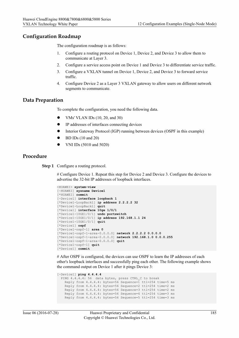
Configuration Roadmap
The configuration roadmap is as follows:
1. Configure a routing protocol on Device 1, Device 2, and Device 3 to allow them tocommunicate at Layer 3.
2. Configure a service access point on Device 1 and Device 3 to differentiate service traffic.3. Configure a VXLAN tunnel on Device 1, Device 2, and Device 3 to forward service
traffic.4. Configure Device 2 as a Layer 3 VXLAN gateway to allow users on different network
segments to communicate.
Data Preparation
To complete the configuration, you need the following data.
l VMs' VLAN IDs (10, 20, and 30)l IP addresses of interfaces connecting devicesl Interior Gateway Protocol (IGP) running between devices (OSPF in this example)l BD IDs (10 and 20)l VNI IDs (5010 and 5020)
Procedure
Step 1 Configure a routing protocol.
# Configure Device 1. Repeat this step for Device 2 and Device 3. Configure the devices toadvertise the 32-bit IP addresses of loopback interfaces.
<HUAWEI> system-view[~HUAWEI] sysname Device1[*HUAWEI] commit[~Device1] interface loopback 1[*Device1-LoopBack1] ip address 2.2.2.2 32[*Device1-LoopBack1] quit[*Device1] interface 10ge 1/0/1[*Device1-10GE1/0/1] undo portswitch[*Device1-10GE1/0/1] ip address 192.168.1.1 24[*Device1-10GE1/0/1] quit[*Device1] ospf[*Device1-ospf-1] area 0[*Device1-ospf-1-area-0.0.0.0] network 2.2.2.2 0.0.0.0[*Device1-ospf-1-area-0.0.0.0] network 192.168.1.0 0.0.0.255[*Device1-ospf-1-area-0.0.0.0] quit[*Device1-ospf-1] quit[*Device1] commit
# After OSPF is configured, the devices can use OSPF to learn the IP addresses of eachother's loopback interfaces and successfully ping each other. The following example showsthe command output on Device 1 after it pings Device 3:
[~Device1] ping 4.4.4.4 PING 4.4.4.4: 56 data bytes, press CTRL_C to break Reply from 4.4.4.4: bytes=56 Sequence=1 ttl=254 time=5 ms Reply from 4.4.4.4: bytes=56 Sequence=2 ttl=254 time=2 ms Reply from 4.4.4.4: bytes=56 Sequence=3 ttl=254 time=2 ms Reply from 4.4.4.4: bytes=56 Sequence=4 ttl=254 time=3 ms Reply from 4.4.4.4: bytes=56 Sequence=5 ttl=254 time=3 ms
Huawei CloudEngine 8800&7800&6800&5800 SeriesVXLAN Technology White Paper 12 Configuration Examples (Single-Node Mode)
Issue 06 (2016-07-28) Huawei Proprietary and ConfidentialCopyright © Huawei Technologies Co., Ltd.
185
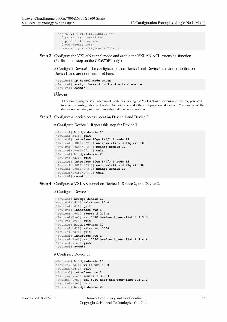
--- 4.4.4.4 ping statistics --- 5 packet(s) transmitted 5 packet(s) received 0.00% packet loss round-trip min/avg/max = 2/3/5 ms
Step 2 Configure the VXLAN tunnel mode and enable the VXLAN ACL extension function.(Perform this step on the CE6870EI only.)
# Configure Device1. The configurations on Device2 and Device3 are similar to that onDevice1, and are not mentioned here.
[~Device1] ip tunnel mode vxlan[*Device1] assign forward nvo3 acl extend enable[*Device1] commit
NOTE
After modifying the VXLAN tunnel mode or enabling the VXLAN ACL extension function, you needto save the configuration and restart the device to make the configuration take effect. You can restart thedevice immediately or after completing all the configurations.
Step 3 Configure a service access point on Device 1 and Device 3.
# Configure Device 1. Repeat this step for Device 3.
[~Device1] bridge-domain 10[*Device1-bd10] quit[*Device1] interface 10ge 1/0/2.1 mode l2[*Device1-10GE1/0/2.1] encapsulation dot1q vid 10[*Device1-10GE1/0/2.1] bridge-domain 10[*Device1-10GE1/0/2.1] quit[*Device1] bridge-domain 20[*Device1-bd20] quit[*Device1] interface 10ge 1/0/3.1 mode l2[*Device1-10GE1/0/3.1] encapsulation dot1q vid 30[*Device1-10GE1/0/3.1] bridge-domain 20[*Device1-10GE1/0/3.1] quit[*Device1] commit
Step 4 Configure a VXLAN tunnel on Device 1, Device 2, and Device 3.
# Configure Device 1.
[~Device1] bridge-domain 10[~Device1-bd10] vxlan vni 5010[*Device1-bd10] quit[*Device1] interface nve 1[*Device1-Nve1] source 2.2.2.2[*Device1-Nve1] vni 5010 head-end peer-list 3.3.3.3[*Device1-Nve1] quit[*Device1] bridge-domain 20[*Device1-bd20] vxlan vni 5020[*Device1-bd20] quit[*Device1] interface nve 1[*Device1-Nve1] vni 5020 head-end peer-list 4.4.4.4[*Device1-Nve1] quit[*Device1] commit
# Configure Device 2.
[~Device2] bridge-domain 10[*Device2-bd10] vxlan vni 5010[*Device2-bd10] quit[*Device2] interface nve 1[*Device2-Nve1] source 3.3.3.3[*Device2-Nve1] vni 5010 head-end peer-list 2.2.2.2[*Device2-Nve1] quit[*Device2] bridge-domain 20
Huawei CloudEngine 8800&7800&6800&5800 SeriesVXLAN Technology White Paper 12 Configuration Examples (Single-Node Mode)
Issue 06 (2016-07-28) Huawei Proprietary and ConfidentialCopyright © Huawei Technologies Co., Ltd.
186

[*Device2-bd20] vxlan vni 5020[*Device2-bd20] quit[*Device2] interface nve 1[*Device2-Nve1] source 3.3.3.3[*Device2-Nve1] vni 5020 head-end peer-list 4.4.4.4[*Device2-Nve1] quit[*Device2] commit
# Configure Device 3.
[~Device3] bridge-domain 20[~Device3-bd20] vxlan vni 5020[*Device3-bd20] quit[*Device3] interface nve 1[*Device3-Nve1] source 4.4.4.4[*Device3-Nve1] vni 5020 head-end peer-list 3.3.3.3[*Device3-Nve1] vni 5020 head-end peer-list 2.2.2.2[*Device3-Nve1] quit[*Device3] commit
Step 5 Configure a service loopback interface on Device 2. (You do not need to perform this step onthe CE6855HI, CE6870EI, and CE7855EI.)[~Device2] interface eth-trunk 1[*Device2-Eth-Trunk1] service type tunnel[*Device2-Eth-Trunk1] quit[*Device2] interface 10ge 1/0/4[*Device2-10GE1/0/4] eth-trunk 1[*Device2-10GE1/0/4] quit[*Device2] commit
Step 6 Configure Device 2 as a Layer 3 VXLAN gateway.[~Device2] interface vbdif 10[*Device2-Vbdif10] ip address 192.168.10.10 24[*Device2-Vbdif10] quit[*Device2] interface vbdif 20[*Device2-Vbdif20] ip address 192.168.20.10 24[*Device2-Vbdif20] quit[*Device2] commit
Step 7 Verify the configuration.
After completing the configurations, run the display vxlan tunnel and display vxlan vnicommands on Device 1, Device 2, and Device 3 to check the VXLAN tunnel and VNIinformation, respectively. The VNIs are Up on Device 1, Device 2, and Device 3. Thefollowing example shows the command output on Device 2:
[~Device2] display vxlan tunnelNumber of vxlan tunnel : 2Tunnel ID Source Destination State Type--------------------------------------------------------------40265318411 3.3.3.3 2.2.2.2 up static40265318412 3.3.3.3 4.4.4.4 up static[~Device2] display vxlan vniNumber of vxlan vni : 2VNI BD-ID State---------------------------------------5010 10 up5020 20 up
VM1s on different servers can communicate.
----End
Configuration Filesl Device 1 configuration file
Huawei CloudEngine 8800&7800&6800&5800 SeriesVXLAN Technology White Paper 12 Configuration Examples (Single-Node Mode)
Issue 06 (2016-07-28) Huawei Proprietary and ConfidentialCopyright © Huawei Technologies Co., Ltd.
187
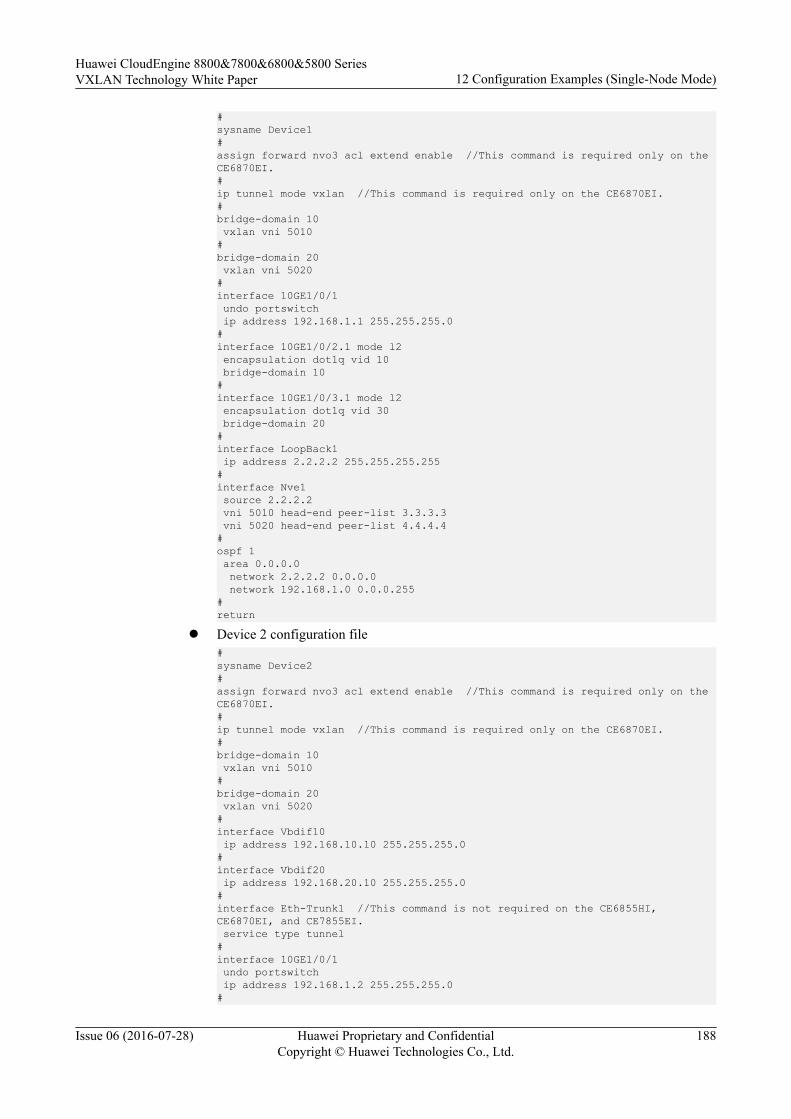
#sysname Device1#assign forward nvo3 acl extend enable //This command is required only on the CE6870EI.#ip tunnel mode vxlan //This command is required only on the CE6870EI.#bridge-domain 10 vxlan vni 5010#bridge-domain 20 vxlan vni 5020#interface 10GE1/0/1 undo portswitch ip address 192.168.1.1 255.255.255.0#interface 10GE1/0/2.1 mode l2 encapsulation dot1q vid 10 bridge-domain 10#interface 10GE1/0/3.1 mode l2 encapsulation dot1q vid 30 bridge-domain 20#interface LoopBack1 ip address 2.2.2.2 255.255.255.255#interface Nve1 source 2.2.2.2 vni 5010 head-end peer-list 3.3.3.3 vni 5020 head-end peer-list 4.4.4.4#ospf 1 area 0.0.0.0 network 2.2.2.2 0.0.0.0 network 192.168.1.0 0.0.0.255#return
l Device 2 configuration file#sysname Device2#assign forward nvo3 acl extend enable //This command is required only on the CE6870EI.#ip tunnel mode vxlan //This command is required only on the CE6870EI.#bridge-domain 10 vxlan vni 5010#bridge-domain 20 vxlan vni 5020#interface Vbdif10 ip address 192.168.10.10 255.255.255.0#interface Vbdif20 ip address 192.168.20.10 255.255.255.0#interface Eth-Trunk1 //This command is not required on the CE6855HI, CE6870EI, and CE7855EI. service type tunnel #interface 10GE1/0/1 undo portswitch ip address 192.168.1.2 255.255.255.0#
Huawei CloudEngine 8800&7800&6800&5800 SeriesVXLAN Technology White Paper 12 Configuration Examples (Single-Node Mode)
Issue 06 (2016-07-28) Huawei Proprietary and ConfidentialCopyright © Huawei Technologies Co., Ltd.
188
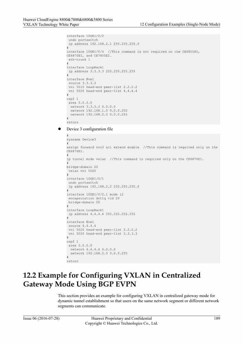
interface 10GE1/0/2 undo portswitch ip address 192.168.2.1 255.255.255.0#interface 10GE1/0/4 //This command is not required on the CE6855HI, CE6870EI, and CE7855EI. eth-trunk 1 #interface LoopBack1 ip address 3.3.3.3 255.255.255.255#interface Nve1 source 3.3.3.3 vni 5010 head-end peer-list 2.2.2.2 vni 5020 head-end peer-list 4.4.4.4#ospf 1 area 0.0.0.0 network 3.3.3.3 0.0.0.0 network 192.168.1.0 0.0.0.255 network 192.168.2.0 0.0.0.255#return
l Device 3 configuration file#sysname Device3#assign forward nvo3 acl extend enable //This command is required only on the CE6870EI.#ip tunnel mode vxlan //This command is required only on the CE6870EI.#bridge-domain 20 vxlan vni 5020#interface 10GE1/0/1 undo portswitch ip address 192.168.2.2 255.255.255.0#interface 10GE1/0/2.1 mode l2 encapsulation dot1q vid 20 bridge-domain 20#interface LoopBack1 ip address 4.4.4.4 255.255.255.255#interface Nve1 source 4.4.4.4 vni 5020 head-end peer-list 2.2.2.2 vni 5020 head-end peer-list 3.3.3.3#ospf 1 area 0.0.0.0 network 4.4.4.4 0.0.0.0 network 192.168.2.0 0.0.0.255#return
12.2 Example for Configuring VXLAN in CentralizedGateway Mode Using BGP EVPN
This section provides an example for configuring VXLAN in centralized gateway mode fordynamic tunnel establishment so that users on the same network segment or different networksegments can communicate.
Huawei CloudEngine 8800&7800&6800&5800 SeriesVXLAN Technology White Paper 12 Configuration Examples (Single-Node Mode)
Issue 06 (2016-07-28) Huawei Proprietary and ConfidentialCopyright © Huawei Technologies Co., Ltd.
189

Networking Requirements
On the network shown in Figure 12-2, an enterprise has VMs deployed in different datacenters. VM 1 on Server 1 belongs to VLAN 10, VM 1 on Server 2 belongs to VLAN 20, andVM 1 on Server 3 belongs to VLAN 30. Server 1 and Server 2 reside on different networksegments, whereas Server 2 and Server 3 reside on the same network segment. To allowVM1s in different data centers to communicate with each other, configure a Layer 3 VXLANgateway.
Figure 12-2 VXLAN in centralized gateway mode for dynamic tunnel establishment
NOTE
Interface 1, Interface 2, and Interface 3 represent 10GE 1/0/1, 10GE 1/0/2, and 10GE 1/0/3, respectively.
Server1192.168.10.1/24
Server2192.168.20.1/24
VM1 VMm
VSwitch VSwitch
VM1 VMn
inte
rface
2
interface2
NVE
Loopback 13.3.3.3/32
... ...
VLAN 10 VLAN 20
Device2
interf
ace1
192.1
68.1.
1/24
interf
ace1
192.1
68.1.
2/24
interface2
192.168.2.1/24
interface1
192.168.2.2/24
L3 Gateway IP Address:BDIF10:192.168.10.10/24BDIF20:192.168.20.10/24
Device1Loopback 12.2.2.2/32
Loopback 14.4.4.4/32
Device3
Server3192.168.20.2/24
VM1 VMm
VSwitch
...
VLAN 30
interface3
VXLAN Tunnel
VXLAN Tun
nel VXLAN Tunnel
Configuration Roadmap
The configuration roadmap is as follows:
1. Configure a routing protocol on Device 1, Device 2, and Device 3 to allow them tocommunicate at Layer 3.
Huawei CloudEngine 8800&7800&6800&5800 SeriesVXLAN Technology White Paper 12 Configuration Examples (Single-Node Mode)
Issue 06 (2016-07-28) Huawei Proprietary and ConfidentialCopyright © Huawei Technologies Co., Ltd.
190
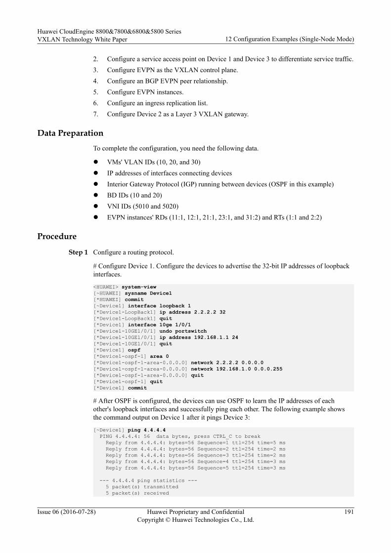
2. Configure a service access point on Device 1 and Device 3 to differentiate service traffic.3. Configure EVPN as the VXLAN control plane.4. Configure an BGP EVPN peer relationship.5. Configure EVPN instances.6. Configure an ingress replication list.7. Configure Device 2 as a Layer 3 VXLAN gateway.
Data Preparation
To complete the configuration, you need the following data.
l VMs' VLAN IDs (10, 20, and 30)l IP addresses of interfaces connecting devicesl Interior Gateway Protocol (IGP) running between devices (OSPF in this example)l BD IDs (10 and 20)l VNI IDs (5010 and 5020)l EVPN instances' RDs (11:1, 12:1, 21:1, 23:1, and 31:2) and RTs (1:1 and 2:2)
Procedure
Step 1 Configure a routing protocol.
# Configure Device 1. Configure the devices to advertise the 32-bit IP addresses of loopbackinterfaces.
<HUAWEI> system-view[~HUAWEI] sysname Device1[*HUAWEI] commit[~Device1] interface loopback 1[*Device1-LoopBack1] ip address 2.2.2.2 32[*Device1-LoopBack1] quit[*Device1] interface 10ge 1/0/1[*Device1-10GE1/0/1] undo portswitch[*Device1-10GE1/0/1] ip address 192.168.1.1 24[*Device1-10GE1/0/1] quit[*Device1] ospf[*Device1-ospf-1] area 0[*Device1-ospf-1-area-0.0.0.0] network 2.2.2.2 0.0.0.0[*Device1-ospf-1-area-0.0.0.0] network 192.168.1.0 0.0.0.255[*Device1-ospf-1-area-0.0.0.0] quit[*Device1-ospf-1] quit[*Device1] commit
# After OSPF is configured, the devices can use OSPF to learn the IP addresses of eachother's loopback interfaces and successfully ping each other. The following example showsthe command output on Device 1 after it pings Device 3:
[~Device1] ping 4.4.4.4 PING 4.4.4.4: 56 data bytes, press CTRL_C to break Reply from 4.4.4.4: bytes=56 Sequence=1 ttl=254 time=5 ms Reply from 4.4.4.4: bytes=56 Sequence=2 ttl=254 time=2 ms Reply from 4.4.4.4: bytes=56 Sequence=3 ttl=254 time=2 ms Reply from 4.4.4.4: bytes=56 Sequence=4 ttl=254 time=3 ms Reply from 4.4.4.4: bytes=56 Sequence=5 ttl=254 time=3 ms
--- 4.4.4.4 ping statistics --- 5 packet(s) transmitted 5 packet(s) received
Huawei CloudEngine 8800&7800&6800&5800 SeriesVXLAN Technology White Paper 12 Configuration Examples (Single-Node Mode)
Issue 06 (2016-07-28) Huawei Proprietary and ConfidentialCopyright © Huawei Technologies Co., Ltd.
191

0.00% packet loss round-trip min/avg/max = 2/3/5 ms
Step 2 Configure the VXLAN tunnel mode and enable the VXLAN ACL extension function.(Perform this step on the CE6870EI only.)
# Configure Device1. The configurations on Device2 and Device3 are similar to that onDevice1, and are not mentioned here.
[~Device1] ip tunnel mode vxlan[*Device1] assign forward nvo3 acl extend enable[*Device1] commit
NOTE
After modifying the VXLAN tunnel mode or enabling the VXLAN ACL extension function, you needto save the configuration and restart the device to make the configuration take effect. You can restart thedevice immediately or after completing all the configurations.
Step 3 Configure a service access point on Device 1 and Device 3.
# Configure Device 1. Repeat this step for Device 3.
[~Device1] bridge-domain 10[*Device1-bd10] quit[*Device1] interface 10ge 1/0/2.1 mode l2[*Device1-10GE1/0/2.1] encapsulation dot1q vid 10[*Device1-10GE1/0/2.1] bridge-domain 10[*Device1-10GE1/0/2.1] quit[*Device1] bridge-domain 20[*Device1-bd20] quit[*Device1] interface 10ge 1/0/3.1 mode l2[*Device1-10GE1/0/3.1] encapsulation dot1q vid 30[*Device1-10GE1/0/3.1] bridge-domain 20[*Device1-10GE1/0/3.1] quit[*Device1] commit
Step 4 Configure EVPN as the VXLAN control plane on Device 1, Device 2, and Device 3.
# Configure Device 1. Repeat this step for Device 2 and Device 3.
[~Device1] evpn-overlay enable[*Device1] commit
Step 5 Configure an BGP EVPN peer relationship.
# Configure Device 1. Repeat this step for Device 2 and Device 3.
[~Device1] bgp 100 instance evpn1[*Device1-bgp-instance-evpn1] peer 3.3.3.3 as-number 100[*Device1-bgp-instance-evpn1] peer 3.3.3.3 connect-interface LoopBack1[*Device1-bgp-instance-evpn1] peer 4.4.4.4 as-number 100[*Device1-bgp-instance-evpn1] peer 4.4.4.4 connect-interface LoopBack1[*Device1-bgp-instance-evpn1] l2vpn-family evpn[*Device1-bgp-instance-evpn1-af-evpn] peer 3.3.3.3 enable[*Device1-bgp-instance-evpn1-af-evpn] peer 4.4.4.4 enable[*Device1-bgp-instance-evpn1-af-evpn] quit[*Device1-bgp-instance-evpn1] quit[*Device1] commit
Step 6 Configure an EVPN instance on Device 1, Device 2, and Device 3.
# Configure Device 1. Repeat this step for Device 2 and Device 3.
[~Device1] bridge-domain 10[~Device1-bd10] vxlan vni 5010[*Device1-bd10] evpn[*Device1-bd10-evpn] route-distinguisher 11:1[*Device1-bd10-evpn] vpn-target 1:1
Huawei CloudEngine 8800&7800&6800&5800 SeriesVXLAN Technology White Paper 12 Configuration Examples (Single-Node Mode)
Issue 06 (2016-07-28) Huawei Proprietary and ConfidentialCopyright © Huawei Technologies Co., Ltd.
192

[*Device1-bd10-evpn] quit[*Device1-bd10] quit[*Device1] bridge-domain 20[*Device1-bd20] vxlan vni 5020[*Device1-bd20] evpn[*Device1-bd20-evpn] route-distinguisher 12:1[*Device1-bd20-evpn] vpn-target 2:2[*Device1-bd20-evpn] quit[*Device1-bd20] quit[*Device1] commit
Step 7 Configure an ingress replication list.
# Configure Device 1. Repeat this step for Device 2 and Device 3.
[~Device1] interface nve 1[*Device1-Nve1] source 2.2.2.2[*Device1-Nve1] vni 5010 head-end peer-list protocol bgp[*Device1-Nve1] vni 5020 head-end peer-list protocol bgp[*Device1-Nve1] quit[*Device1] commit
Step 8 Configure a service loopback interface on Device 2. (You do not need to perform this step onthe CE6855HI, CE6870EI, and CE7855EI.)[~Device2] interface eth-trunk 1[*Device2-Eth-Trunk1] service type tunnel[*Device2-Eth-Trunk1] quit[*Device2] interface 10ge 1/0/4[*Device2-10GE1/0/4] eth-trunk 1[*Device2-10GE1/0/4] quit[*Device2] commit
Step 9 Configure Device 2 as a Layer 3 VXLAN gateway.[~Device2] interface vbdif 10[*Device2-Vbdif10] ip address 192.168.10.10 24[*Device2-Vbdif10] quit[*Device2] interface vbdif 20[*Device2-Vbdif20] ip address 192.168.20.10 24[*Device2-Vbdif20] quit[*Device2] commit
Step 10 Verify the configuration.
After completing the configurations, run the display vxlan tunnel and display vxlan vnicommands on Device 1, Device 2, and Device 3 to check the VXLAN tunnel and VNIinformation, respectively. The VNIs are Up. The following example shows the commandoutput on Device 1.
[~Device1] display vxlan tunnelNumber of vxlan tunnel : 2Tunnel ID Source Destination State Type--------------------------------------------------------------4026531843 2.2.2.2 3.3.3.3 up dynamic4026531844 2.2.2.2 4.4.4.4 up dynamic[~Device1] display vxlan vniNumber of vxlan vni : 2VNI BD-ID State---------------------------------------5010 10 up5020 20 up
VM1s on different servers can communicate.
----End
Huawei CloudEngine 8800&7800&6800&5800 SeriesVXLAN Technology White Paper 12 Configuration Examples (Single-Node Mode)
Issue 06 (2016-07-28) Huawei Proprietary and ConfidentialCopyright © Huawei Technologies Co., Ltd.
193

Configuration Filesl Device 1 configuration file
#sysname Device1#assign forward nvo3 acl extend enable //This command is required only on the CE6870EI.#ip tunnel mode vxlan //This command is required only on the CE6870EI.#evpn-overlay enable#bridge-domain 10 vxlan vni 5010 evpn route-distinguisher 11:1 vpn-target 1:1 export-extcommunity vpn-target 1:1 import-extcommunity#bridge-domain 20 vxlan vni 5020 evpn route-distinguisher 12:1 vpn-target 2:2 export-extcommunity vpn-target 2:2 import-extcommunity#interface 10GE1/0/1 undo portswitch ip address 192.168.1.1 255.255.255.0#interface 10GE1/0/2.1 mode l2 encapsulation dot1q vid 10 bridge-domain 10#interface 10GE1/0/3.1 mode l2 encapsulation dot1q vid 30 bridge-domain 20#interface LoopBack1 ip address 2.2.2.2 255.255.255.255#interface Nve1 source 2.2.2.2 vni 5010 head-end peer-list protocol bgp vni 5020 head-end peer-list protocol bgp#bgp 100 instance evpn1 peer 3.3.3.3 as-number 100 peer 3.3.3.3 connect-interface LoopBack1 peer 4.4.4.4 as-number 100 peer 4.4.4.4 connect-interface LoopBack1 # l2vpn-family evpn policy vpn-target peer 3.3.3.3 enable peer 4.4.4.4 enable#ospf 1 area 0.0.0.0 network 2.2.2.2 0.0.0.0 network 192.168.1.0 0.0.0.255#return
l Device 2 configuration file#sysname Device2#
Huawei CloudEngine 8800&7800&6800&5800 SeriesVXLAN Technology White Paper 12 Configuration Examples (Single-Node Mode)
Issue 06 (2016-07-28) Huawei Proprietary and ConfidentialCopyright © Huawei Technologies Co., Ltd.
194
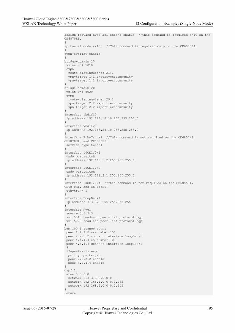
assign forward nvo3 acl extend enable //This command is required only on the CE6870EI.#ip tunnel mode vxlan //This command is required only on the CE6870EI.#evpn-overlay enable#bridge-domain 10 vxlan vni 5010 evpn route-distinguisher 21:1 vpn-target 1:1 export-extcommunity vpn-target 1:1 import-extcommunity#bridge-domain 20 vxlan vni 5020 evpn route-distinguisher 23:1 vpn-target 2:2 export-extcommunity vpn-target 2:2 import-extcommunity#interface Vbdif10 ip address 192.168.10.10 255.255.255.0#interface Vbdif20 ip address 192.168.20.10 255.255.255.0#interface Eth-Trunk1 //This command is not required on the CE6855HI, CE6870EI, and CE7855EI. service type tunnel #interface 10GE1/0/1 undo portswitch ip address 192.168.1.2 255.255.255.0#interface 10GE1/0/2 undo portswitch ip address 192.168.2.1 255.255.255.0#interface 10GE1/0/4 //This command is not required on the CE6855HI, CE6870EI, and CE7855EI. eth-trunk 1 #interface LoopBack1 ip address 3.3.3.3 255.255.255.255#interface Nve1 source 3.3.3.3 vni 5010 head-end peer-list protocol bgp vni 5020 head-end peer-list protocol bgp#bgp 100 instance evpn1 peer 2.2.2.2 as-number 100 peer 2.2.2.2 connect-interface LoopBack1 peer 4.4.4.4 as-number 100 peer 4.4.4.4 connect-interface LoopBack1 # l2vpn-family evpn policy vpn-target peer 2.2.2.2 enable peer 4.4.4.4 enable#ospf 1 area 0.0.0.0 network 3.3.3.3 0.0.0.0 network 192.168.1.0 0.0.0.255 network 192.168.2.0 0.0.0.255#return
Huawei CloudEngine 8800&7800&6800&5800 SeriesVXLAN Technology White Paper 12 Configuration Examples (Single-Node Mode)
Issue 06 (2016-07-28) Huawei Proprietary and ConfidentialCopyright © Huawei Technologies Co., Ltd.
195
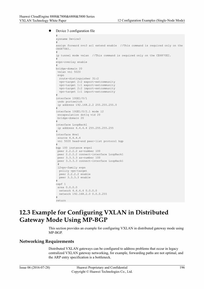
l Device 3 configuration file#sysname Device3#assign forward nvo3 acl extend enable //This command is required only on the CE6870EI.#ip tunnel mode vxlan //This command is required only on the CE6870EI.#evpn-overlay enable#bridge-domain 20 vxlan vni 5020 evpn route-distinguisher 31:2 vpn-target 2:2 export-extcommunity vpn-target 1:1 export-extcommunity vpn-target 2:2 import-extcommunity vpn-target 1:1 import-extcommunity#interface 10GE1/0/1 undo portswitch ip address 192.168.2.2 255.255.255.0#interface 10GE1/0/2.1 mode l2 encapsulation dot1q vid 20 bridge-domain 20#interface LoopBack1 ip address 4.4.4.4 255.255.255.255#interface Nve1 source 4.4.4.4 vni 5020 head-end peer-list protocol bgp#bgp 100 instance evpn1 peer 2.2.2.2 as-number 100 peer 2.2.2.2 connect-interface LoopBack1 peer 3.3.3.3 as-number 100 peer 3.3.3.3 connect-interface LoopBack1 # l2vpn-family evpn policy vpn-target peer 2.2.2.2 enable peer 3.3.3.3 enable#ospf 1 area 0.0.0.0 network 4.4.4.4 0.0.0.0 network 192.168.2.0 0.0.0.255#return
12.3 Example for Configuring VXLAN in DistributedGateway Mode Using MP-BGP
This section provides an example for configuring VXLAN in distributed gateway mode usingMP-BGP.
Networking RequirementsDistributed VXLAN gateways can be configured to address problems that occur in legacycentralized VXLAN gateway networking, for example, forwarding paths are not optimal, andthe ARP entry specification is a bottleneck.
Huawei CloudEngine 8800&7800&6800&5800 SeriesVXLAN Technology White Paper 12 Configuration Examples (Single-Node Mode)
Issue 06 (2016-07-28) Huawei Proprietary and ConfidentialCopyright © Huawei Technologies Co., Ltd.
196
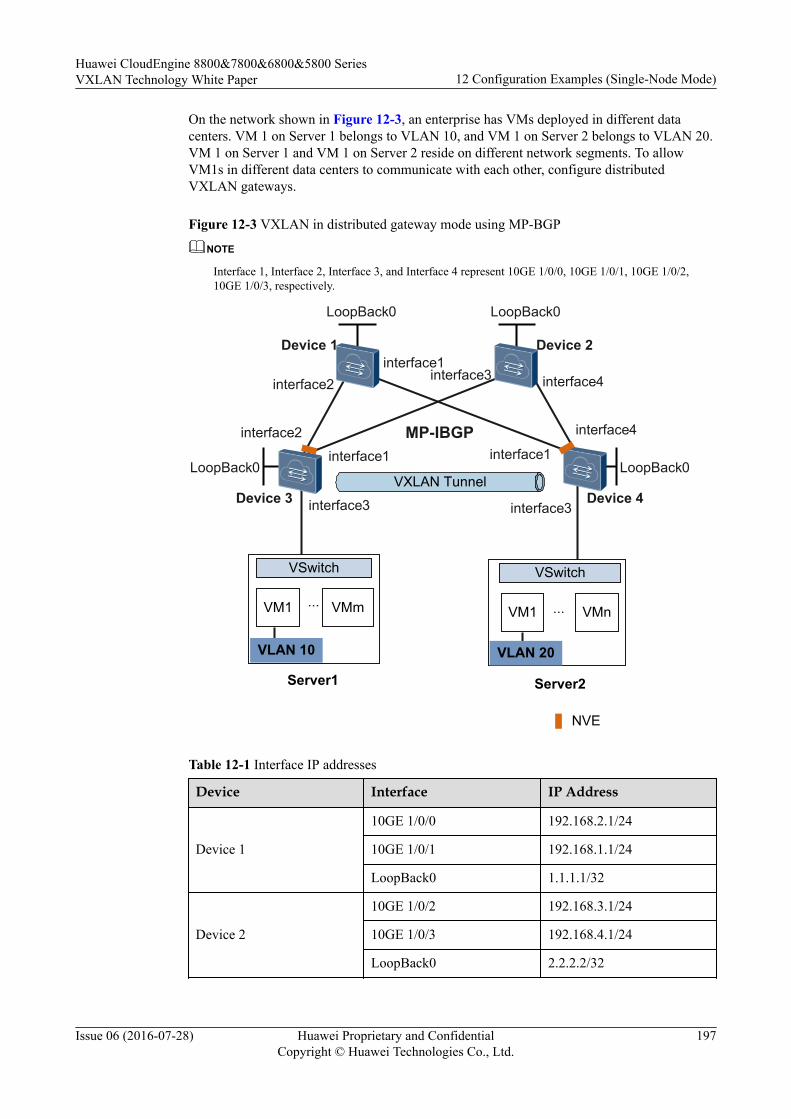
On the network shown in Figure 12-3, an enterprise has VMs deployed in different datacenters. VM 1 on Server 1 belongs to VLAN 10, and VM 1 on Server 2 belongs to VLAN 20.VM 1 on Server 1 and VM 1 on Server 2 reside on different network segments. To allowVM1s in different data centers to communicate with each other, configure distributedVXLAN gateways.
Figure 12-3 VXLAN in distributed gateway mode using MP-BGP
NOTE
Interface 1, Interface 2, Interface 3, and Interface 4 represent 10GE 1/0/0, 10GE 1/0/1, 10GE 1/0/2,10GE 1/0/3, respectively.
Server1 Server2
VM1 VMm
VSwitch VSwitch
VM1 VMn
NVE
... ...
VLAN 10 VLAN 20
VXLAN Tunnel
MP-IBGP
Device 1 Device 2
Device 3 Device 4
LoopBack0 LoopBack0
LoopBack0 LoopBack0
interface2
interface2
interface1
interface1interface1
interface3 interface4
interface4
interface3 interface3
Table 12-1 Interface IP addresses
Device Interface IP Address
Device 1
10GE 1/0/0 192.168.2.1/24
10GE 1/0/1 192.168.1.1/24
LoopBack0 1.1.1.1/32
Device 2
10GE 1/0/2 192.168.3.1/24
10GE 1/0/3 192.168.4.1/24
LoopBack0 2.2.2.2/32
Huawei CloudEngine 8800&7800&6800&5800 SeriesVXLAN Technology White Paper 12 Configuration Examples (Single-Node Mode)
Issue 06 (2016-07-28) Huawei Proprietary and ConfidentialCopyright © Huawei Technologies Co., Ltd.
197
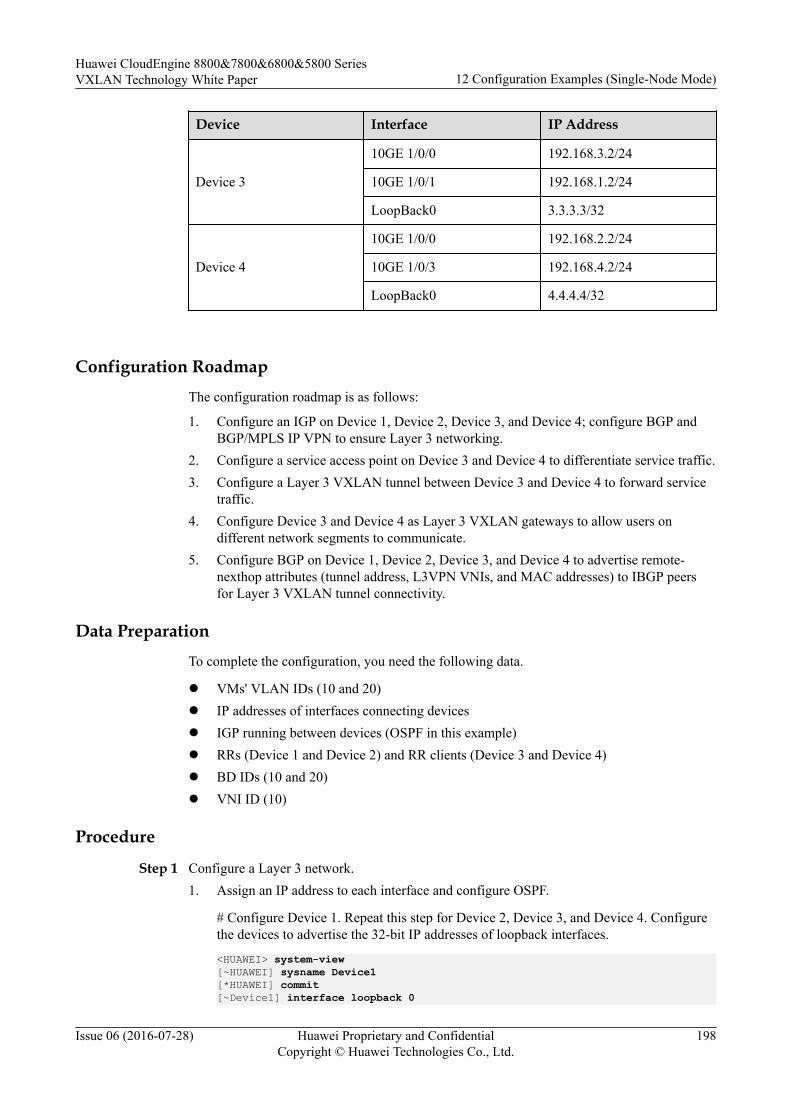
Device Interface IP Address
Device 3
10GE 1/0/0 192.168.3.2/24
10GE 1/0/1 192.168.1.2/24
LoopBack0 3.3.3.3/32
Device 4
10GE 1/0/0 192.168.2.2/24
10GE 1/0/3 192.168.4.2/24
LoopBack0 4.4.4.4/32
Configuration RoadmapThe configuration roadmap is as follows:
1. Configure an IGP on Device 1, Device 2, Device 3, and Device 4; configure BGP andBGP/MPLS IP VPN to ensure Layer 3 networking.
2. Configure a service access point on Device 3 and Device 4 to differentiate service traffic.3. Configure a Layer 3 VXLAN tunnel between Device 3 and Device 4 to forward service
traffic.4. Configure Device 3 and Device 4 as Layer 3 VXLAN gateways to allow users on
different network segments to communicate.5. Configure BGP on Device 1, Device 2, Device 3, and Device 4 to advertise remote-
nexthop attributes (tunnel address, L3VPN VNIs, and MAC addresses) to IBGP peersfor Layer 3 VXLAN tunnel connectivity.
Data PreparationTo complete the configuration, you need the following data.
l VMs' VLAN IDs (10 and 20)l IP addresses of interfaces connecting devicesl IGP running between devices (OSPF in this example)l RRs (Device 1 and Device 2) and RR clients (Device 3 and Device 4)l BD IDs (10 and 20)l VNI ID (10)
Procedure
Step 1 Configure a Layer 3 network.1. Assign an IP address to each interface and configure OSPF.
# Configure Device 1. Repeat this step for Device 2, Device 3, and Device 4. Configurethe devices to advertise the 32-bit IP addresses of loopback interfaces.
<HUAWEI> system-view[~HUAWEI] sysname Device1[*HUAWEI] commit[~Device1] interface loopback 0
Huawei CloudEngine 8800&7800&6800&5800 SeriesVXLAN Technology White Paper 12 Configuration Examples (Single-Node Mode)
Issue 06 (2016-07-28) Huawei Proprietary and ConfidentialCopyright © Huawei Technologies Co., Ltd.
198

[*Device1-LoopBack0] ip address 1.1.1.1 32[*Device1-LoopBack0] quit[*Device1] interface 10ge 1/0/0[*Device1-10GE1/0/0] undo portswitch[*Device1-10GE1/0/0] ip address 192.168.2.1 24[*Device1-10GE1/0/0] quit[*Device1] interface 10ge 1/0/1[*Device1-10GE1/0/1] undo portswitch[*Device1-10GE1/0/1] ip address 192.168.1.1 24[*Device1-10GE1/0/1] quit[*Device1] ospf[*Device1-ospf-1] area 0[*Device1-ospf-1-area-0.0.0.0] network 1.1.1.1 0.0.0.0[*Device1-ospf-1-area-0.0.0.0] network 192.168.1.0 0.0.0.255[*Device1-ospf-1-area-0.0.0.0] network 192.168.2.0 0.0.0.255[*Device1-ospf-1-area-0.0.0.0] quit[*Device1-ospf-1] quit[*Device1] commit
# After OSPF is configured, the devices can use OSPF to learn the IP addresses of eachother's loopback interfaces and successfully ping each other. The following exampleshows the command output on Device 1 after it pings Device 4:
[~Device1] ping 4.4.4.4 PING 4.4.4.4: 56 data bytes, press CTRL_C to break Reply from 4.4.4.4: bytes=56 Sequence=1 ttl=253 time=55 ms Reply from 4.4.4.4: bytes=56 Sequence=2 ttl=253 time=3 ms Reply from 4.4.4.4: bytes=56 Sequence=3 ttl=253 time=4 ms Reply from 4.4.4.4: bytes=56 Sequence=4 ttl=253 time=3 ms Reply from 4.4.4.4: bytes=56 Sequence=5 ttl=253 time=3 ms
--- 4.4.4.4 ping statistics --- 5 packet(s) transmitted 5 packet(s) received 0.00% packet loss round-trip min/avg/max = 3/13/55 ms
2. Configure BGP and BGP/MPLS IP VPN. Configure Device 1 and Device 2 as RRs andDevice 3 and Device 4 as RR clients.
# Configure Device 1. Repeat this step for Device 2.
[~Device1] bgp 100[*Device1-bgp] router-id 1.1.1.1[*Device1-bgp] peer 3.3.3.3 as-number 100[*Device1-bgp] peer 3.3.3.3 connect-interface LoopBack0[*Device1-bgp] peer 4.4.4.4 as-number 100[*Device1-bgp] peer 4.4.4.4 connect-interface LoopBack0[*Device1-bgp] ipv4-family vpnv4[*Device1-bgp-af-vpnv4] undo policy vpn-target[*Device1-bgp-af-vpnv4] peer 3.3.3.3 enable[*Device1-bgp-af-vpnv4] peer 3.3.3.3 reflect-client[*Device1-bgp-af-vpnv4] peer 4.4.4.4 enable[*Device1-bgp-af-vpnv4] peer 4.4.4.4 reflect-client[*Device1-bgp-af-vpnv4] quit[*Device1-bgp] quit[*Device1] commit
# Configure Device 3. Repeat this step for Device 4.
[~Device3] ip vpn-instance vrf1[*Device3-vpn-instance-vrf1] ipv4-family[*Device3-vpn-instance-vrf1-af-ipv4] route-distinguisher 100:1[*Device3-vpn-instance-vrf1-af-ipv4] vpn-target 100:1 export-extcommunity[*Device3-vpn-instance-vrf1-af-ipv4] vpn-target 100:1 import-extcommunity[*Device3-vpn-instance-vrf1-af-ipv4] quit[*Device3-vpn-instance-vrf1] vxlan vni 10[*Device3-vpn-instance-vrf1] quit[*Device3] bgp 100
Huawei CloudEngine 8800&7800&6800&5800 SeriesVXLAN Technology White Paper 12 Configuration Examples (Single-Node Mode)
Issue 06 (2016-07-28) Huawei Proprietary and ConfidentialCopyright © Huawei Technologies Co., Ltd.
199

[*Device3-bgp] router-id 3.3.3.3[*Device3-bgp] peer 1.1.1.1 as-number 100[*Device3-bgp] peer 1.1.1.1 connect-interface LoopBack0[*Device3-bgp] peer 2.2.2.2 as-number 100[*Device3-bgp] peer 2.2.2.2 connect-interface LoopBack0[*Device3-bgp] ipv4-family vpnv4[*Device3-bgp-af-vpnv4] peer 1.1.1.1 enable[*Device3-bgp-af-vpnv4] peer 2.2.2.2 enable[*Device3-bgp-af-vpnv4] quit[*Device3-bgp] ipv4-family vpn-instance vrf1[*Device3-bgp-vrf1] import-route direct[*Device3-bgp-vrf1] quit[*Device3-bgp] quit[*Device3] commit
Step 2 Configure the VXLAN tunnel mode and enable the VXLAN ACL extension function.(Perform this step on the CE6870EI only.)
# Configure Device3. The configurations on Device4 is similar to that on Device3, and are notmentioned here.
[~Device3] ip tunnel mode vxlan[*Device3] assign forward nvo3 acl extend enable[*Device3] commit
NOTE
After modifying the VXLAN tunnel mode or enabling the VXLAN ACL extension function, you needto save the configuration and restart the device to make the configuration take effect. You can restart thedevice immediately or after completing all the configurations.
Step 3 Configure a service access point on Device 3 and Device 4.
# Configure Device 3. Repeat this step for Device 4.
[~Device3] bridge-domain 10[*Device3-bd10] quit[*Device3] interface 10ge 1/0/2.1 mode l2[*Device3-10GE1/0/2.1] encapsulation dot1q vid 10[*Device3-10GE1/0/2.1] bridge-domain 10[*Device3-10GE1/0/2.1] quit[*Device3] commit
Step 4 Establish a Layer 3 VXLAN tunnel between Device 3 and Device 4.
# Configure Device 3. Repeat this step for Device 4.
[~Device3] interface Nve1[*Device3-Nve1] mode l3[*Device3-Nve1] source 3.3.3.3[*Device3-Nve1] quit[*Device3] commit
Step 5 Configure Device 3 and Device 4 as Layer 3 VXLAN gateways.
# Configure a service loopback interface on Device 3. The configuration on Device 4 issimilar to that on Device 3, and is not mentioned here. (You do not need to perform this stepon the CE6855HI, CE6870EI, and CE7855EI.)[~Device3] interface eth-trunk 1[*Device3-Eth-Trunk1] service type tunnel[*Device3-Eth-Trunk1] quit[*Device3] interface 10ge 1/0/4[*Device3-10GE1/0/4] eth-trunk 1[*Device3-10GE1/0/4] quit[*Device3] commit
Huawei CloudEngine 8800&7800&6800&5800 SeriesVXLAN Technology White Paper 12 Configuration Examples (Single-Node Mode)
Issue 06 (2016-07-28) Huawei Proprietary and ConfidentialCopyright © Huawei Technologies Co., Ltd.
200
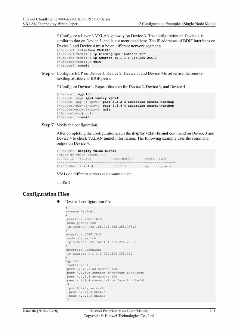
# Configure a Layer 3 VXLAN gateway on Device 3. The configuration on Device 4 issimilar to that on Device 3, and is not mentioned here. The IP addresses of BDIF interfaces onDevice 3 and Device 4 must be on different network segments.[~Device3] interface Vbdif10[*Device3-Vbdif10] ip binding vpn-instance vrf1[*Device3-Vbdif10] ip address 10.1.1.1 255.255.255.0[*Device3-Vbdif10] quit[*Device3] commit
Step 6 Configure BGP on Device 1, Device 2, Device 3, and Device 4 to advertise the remote-nexthop attribute to IBGP peers.
# Configure Device 1. Repeat this step for Device 2, Device 3, and Device 4.
[~Device1] bgp 100[~Device1-bgp] ipv4-family vpnv4[~Device1-bgp-af-vpnv4] peer 3.3.3.3 advertise remote-nexthop[*Device1-bgp-af-vpnv4] peer 4.4.4.4 advertise remote-nexthop[*Device1-bgp-af-vpnv4] quit[*Device1-bgp] quit[*Device1] commit
Step 7 Verify the configuration.
After completing the configurations, run the display vxlan tunnel command on Device 3 andDevice 4 to check VXLAN tunnel information. The following example uses the commandoutput on Device 4.
[~Device4] display vxlan tunnelNumber of vxlan tunnel : 1Tunnel ID Source Destination State Type--------------------------------------------------------------4026531841 4.4.4.4 3.3.3.3 up dynamic
VM1s on different servers can communicate.
----End
Configuration Filesl Device 1 configuration file
#sysname Device1#interface 10GE1/0/0 undo portswitch ip address 192.168.2.1 255.255.255.0#interface 10GE1/0/1 undo portswitch ip address 192.168.1.1 255.255.255.0#interface LoopBack0 ip address 1.1.1.1 255.255.255.255#bgp 100 router-id 1.1.1.1 peer 3.3.3.3 as-number 100 peer 3.3.3.3 connect-interface LoopBack0 peer 4.4.4.4 as-number 100 peer 4.4.4.4 connect-interface LoopBack0 # ipv4-family unicast peer 3.3.3.3 enable peer 4.4.4.4 enable #
Huawei CloudEngine 8800&7800&6800&5800 SeriesVXLAN Technology White Paper 12 Configuration Examples (Single-Node Mode)
Issue 06 (2016-07-28) Huawei Proprietary and ConfidentialCopyright © Huawei Technologies Co., Ltd.
201

ipv4-family vpnv4 undo policy vpn-target peer 3.3.3.3 enable peer 3.3.3.3 reflect-client peer 3.3.3.3 advertise remote-nexthop peer 4.4.4.4 enable peer 4.4.4.4 reflect-client peer 4.4.4.4 advertise remote-nexthop#ospf 1 area 0.0.0.0 network 1.1.1.1 0.0.0.0 network 192.168.1.0 0.0.0.255 network 192.168.2.0 0.0.0.255#return
l Device 2 configuration file#sysname Device2#interface 10GE1/0/2 undo portswitch ip address 192.168.3.1 255.255.255.0#interface 10GE1/0/3 undo portswitch ip address 192.168.4.1 255.255.255.0#interface LoopBack0 ip address 2.2.2.2 255.255.255.255#bgp 100 router-id 2.2.2.2 peer 3.3.3.3 as-number 100 peer 3.3.3.3 connect-interface LoopBack0 peer 4.4.4.4 as-number 100 peer 4.4.4.4 connect-interface LoopBack0 # ipv4-family unicast peer 3.3.3.3 enable peer 4.4.4.4 enable # ipv4-family vpnv4 undo policy vpn-target peer 3.3.3.3 enable peer 3.3.3.3 reflect-client peer 3.3.3.3 advertise remote-nexthop peer 4.4.4.4 enable peer 4.4.4.4 reflect-client peer 4.4.4.4 advertise remote-nexthop#ospf 1 area 0.0.0.0 network 2.2.2.2 0.0.0.0 network 192.168.3.0 0.0.0.255 network 192.168.4.0 0.0.0.255#return
l Device 3 configuration file#sysname Device3#assign forward nvo3 acl extend enable //This command is required only on the CE6870EI.#ip tunnel mode vxlan //This command is required only on the CE6870EI.#ip vpn-instance vrf1
Huawei CloudEngine 8800&7800&6800&5800 SeriesVXLAN Technology White Paper 12 Configuration Examples (Single-Node Mode)
Issue 06 (2016-07-28) Huawei Proprietary and ConfidentialCopyright © Huawei Technologies Co., Ltd.
202
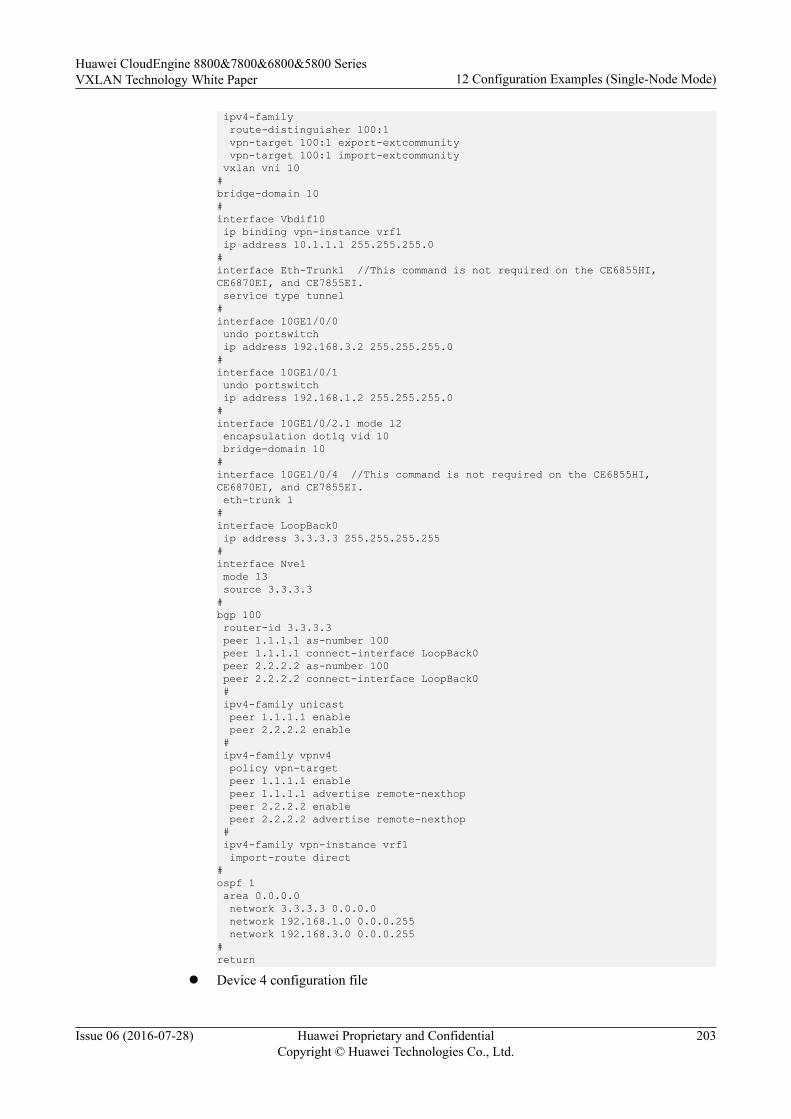
ipv4-family route-distinguisher 100:1 vpn-target 100:1 export-extcommunity vpn-target 100:1 import-extcommunity vxlan vni 10#bridge-domain 10#interface Vbdif10 ip binding vpn-instance vrf1 ip address 10.1.1.1 255.255.255.0#interface Eth-Trunk1 //This command is not required on the CE6855HI, CE6870EI, and CE7855EI. service type tunnel #interface 10GE1/0/0 undo portswitch ip address 192.168.3.2 255.255.255.0#interface 10GE1/0/1 undo portswitch ip address 192.168.1.2 255.255.255.0#interface 10GE1/0/2.1 mode l2 encapsulation dot1q vid 10 bridge-domain 10#interface 10GE1/0/4 //This command is not required on the CE6855HI, CE6870EI, and CE7855EI. eth-trunk 1 #interface LoopBack0 ip address 3.3.3.3 255.255.255.255#interface Nve1 mode l3 source 3.3.3.3#bgp 100 router-id 3.3.3.3 peer 1.1.1.1 as-number 100 peer 1.1.1.1 connect-interface LoopBack0 peer 2.2.2.2 as-number 100 peer 2.2.2.2 connect-interface LoopBack0 # ipv4-family unicast peer 1.1.1.1 enable peer 2.2.2.2 enable # ipv4-family vpnv4 policy vpn-target peer 1.1.1.1 enable peer 1.1.1.1 advertise remote-nexthop peer 2.2.2.2 enable peer 2.2.2.2 advertise remote-nexthop # ipv4-family vpn-instance vrf1 import-route direct#ospf 1 area 0.0.0.0 network 3.3.3.3 0.0.0.0 network 192.168.1.0 0.0.0.255 network 192.168.3.0 0.0.0.255#return
l Device 4 configuration file
Huawei CloudEngine 8800&7800&6800&5800 SeriesVXLAN Technology White Paper 12 Configuration Examples (Single-Node Mode)
Issue 06 (2016-07-28) Huawei Proprietary and ConfidentialCopyright © Huawei Technologies Co., Ltd.
203

#sysname Device4#assign forward nvo3 acl extend enable //This command is required only on the CE6870EI.#ip tunnel mode vxlan //This command is required only on the CE6870EI.#ip vpn-instance vrf1 ipv4-family route-distinguisher 100:1 vpn-target 100:1 export-extcommunity vpn-target 100:1 import-extcommunity vxlan vni 10#bridge-domain 20#interface Vbdif20 ip binding vpn-instance vrf1 ip address 20.1.1.1 255.255.255.0#interface Eth-Trunk1 //This command is not required on the CE6855HI, CE6870EI, and CE7855EI. service type tunnel #interface 10GE1/0/0 undo portswitch ip address 192.168.2.2 255.255.255.0#interface 10GE1/0/2.1 mode l2 encapsulation dot1q vid 20 bridge-domain 20#interface 10GE1/0/3 undo portswitch ip address 192.168.4.2 255.255.255.0#interface 10GE1/0/4 //This command is not required on the CE6855HI, CE6870EI, and CE7855EI. eth-trunk 1 #interface LoopBack0 ip address 4.4.4.4 255.255.255.255#interface Nve2 mode l3 source 4.4.4.4#bgp 100 router-id 4.4.4.4 peer 1.1.1.1 as-number 100 peer 1.1.1.1 connect-interface LoopBack0 peer 2.2.2.2 as-number 100 peer 2.2.2.2 connect-interface LoopBack0 # ipv4-family unicast peer 1.1.1.1 enable peer 2.2.2.2 enable # ipv4-family vpnv4 policy vpn-target peer 1.1.1.1 enable peer 1.1.1.1 advertise remote-nexthop peer 2.2.2.2 enable peer 2.2.2.2 advertise remote-nexthop # ipv4-family vpn-instance vrf1 import-route direct#
Huawei CloudEngine 8800&7800&6800&5800 SeriesVXLAN Technology White Paper 12 Configuration Examples (Single-Node Mode)
Issue 06 (2016-07-28) Huawei Proprietary and ConfidentialCopyright © Huawei Technologies Co., Ltd.
204
ospf 1 area 0.0.0.0 network 4.4.4.4 0.0.0.0 network 192.168.2.0 0.0.0.255 network 192.168.4.0 0.0.0.255#return
12.4 Example for Configuring VXLAN in DistributedGateway Mode Using BGP EVPN
This section provides an example for configuring VXLAN in distributed gateway mode usingBGP EVPN.
Networking RequirementsDistributed VXLAN gateways can be configured to address problems that occur in legacycentralized VXLAN gateway networking, for example, forwarding paths are not optimal, andthe ARP entry specification is a bottleneck.
On the network shown in Figure 12-4, an enterprise has VMs deployed in different datacenters. VM 1 on Server 1 belongs to VLAN 10, and VM 1 on Server 2 belongs to VLAN 20.VM 1 on Server 1 and VM 1 on Server 2 reside on different network segments. To allowVM1s in different data centers to communicate with each other, configure distributedVXLAN gateways. Device 1 is deployed in AS 100, Device 2 is deployed in AS 200, andDevice 3 is deployed in AS300. Device 1, Device 2 and Device 3 use AS 100 for BGP EVPN.
Figure 12-4 VXLAN in distributed gateway mode using BGP EVPN
NOTE
Interface 1 and Interface 2 represent 10GE 1/0/0 and 10GE 1/0/1, respectively.
Huawei CloudEngine 8800&7800&6800&5800 SeriesVXLAN Technology White Paper 12 Configuration Examples (Single-Node Mode)
Issue 06 (2016-07-28) Huawei Proprietary and ConfidentialCopyright © Huawei Technologies Co., Ltd.
205
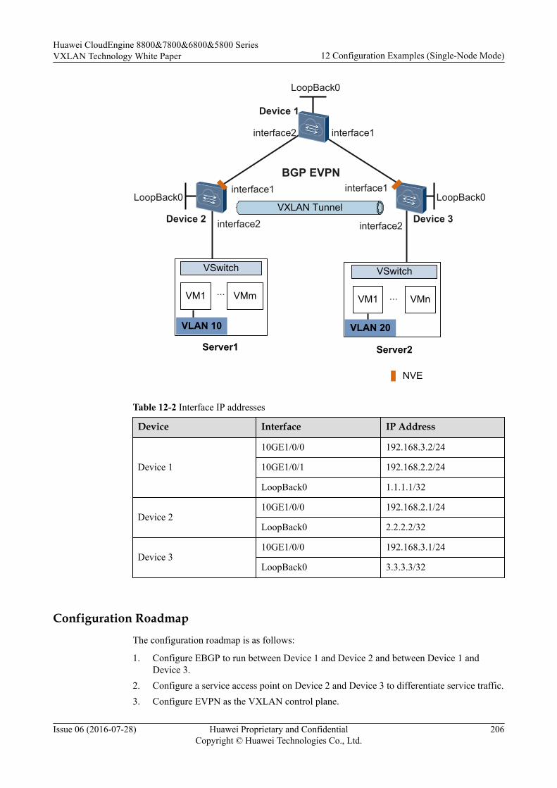
Server1 Server2
VM1 VMm
VSwitch VSwitch
VM1 VMn
NVE
... ...
VLAN 10 VLAN 20
VXLAN Tunnel
BGP EVPN
Device 1
Device 2 Device 3
LoopBack0
LoopBack0 LoopBack0
interface2 interface1
interface1interface1
interface2 interface2
Table 12-2 Interface IP addresses
Device Interface IP Address
Device 1
10GE1/0/0 192.168.3.2/24
10GE1/0/1 192.168.2.2/24
LoopBack0 1.1.1.1/32
Device 210GE1/0/0 192.168.2.1/24
LoopBack0 2.2.2.2/32
Device 310GE1/0/0 192.168.3.1/24
LoopBack0 3.3.3.3/32
Configuration Roadmap
The configuration roadmap is as follows:
1. Configure EBGP to run between Device 1 and Device 2 and between Device 1 andDevice 3.
2. Configure a service access point on Device 2 and Device 3 to differentiate service traffic.3. Configure EVPN as the VXLAN control plane.
Huawei CloudEngine 8800&7800&6800&5800 SeriesVXLAN Technology White Paper 12 Configuration Examples (Single-Node Mode)
Issue 06 (2016-07-28) Huawei Proprietary and ConfidentialCopyright © Huawei Technologies Co., Ltd.
206

4. Specify Device 1 as an BGP EVPN peer for Device 2 and Device 3.
5. Specify Device 2 and Device 3 as BGP EVPN peers for Device 1 and configure Device 2and Device 3 as RR clients.
6. Configure VPN and EVPN instances on Device 2 and Device 3.
7. Configure an ingress replication list on Device 2 and Device 3.
8. Configure Device 2 and Device 3 as Layer 3 VXLAN gateways.
9. Configure BGP to advertise IRB routes between Device 1 and Device 2 and betweenDevice 1 and Device 3.
Data Preparation
To complete the configuration, you need the following data.
l VMs' VLAN IDs (10 and 20)
l IP addresses of interfaces connecting devices
l BD IDs (10 and 20)
l VNI IDs (10 and 20)
l VNI ID (5010)
Procedure
Step 1 Configure a routing protocol.
# Configure Device 1. Repeat this step for Device 2 and Device 3.
<HUAWEI> system-view[~HUAWEI] sysname Device1[*HUAWEI] commit[~Device1] interface loopback 0[*Device1-LoopBack0] ip address 1.1.1.1 32[*Device1-LoopBack0] quit[*Device1] interface 10ge 1/0/0[*Device1-10GE1/0/0] undo portswitch[*Device1-10GE1/0/0] ip address 192.168.3.2 24[*Device1-10GE1/0/0] quit[*Device1] interface 10ge 1/0/1[*Device1-10GE1/0/1] undo portswitch[*Device1-10GE1/0/1] ip address 192.168.2.2 24[*Device1-10GE1/0/1] quit[*Device1] bgp 100[*Device1-bgp] peer 192.168.2.1 as-number 200[*Device1-bgp] peer 192.168.3.1 as-number 300[*Device1-bgp] network 1.1.1.1 32[*Device1-bgp] quit[*Device1] commit
Step 2 Configure the VXLAN tunnel mode and enable the VXLAN ACL extension function.(Perform this step on the CE6870EI only.)
# Configure Device2. The configurations on Device3 is similar to that on Device2, and are notmentioned here.
[~Device2] ip tunnel mode vxlan[*Device2] assign forward nvo3 acl extend enable[*Device2] commit
Huawei CloudEngine 8800&7800&6800&5800 SeriesVXLAN Technology White Paper 12 Configuration Examples (Single-Node Mode)
Issue 06 (2016-07-28) Huawei Proprietary and ConfidentialCopyright © Huawei Technologies Co., Ltd.
207

NOTE
After modifying the VXLAN tunnel mode or enabling the VXLAN ACL extension function, you needto save the configuration and restart the device to make the configuration take effect. You can restart thedevice immediately or after completing all the configurations.
Step 3 Configure a service access point on Device 2 and Device 3.
# Configure Device 2. Repeat this step for Device 3.
[~Device2] bridge-domain 10[*Device2-bd10] quit[*Device2] interface 10ge 1/0/1.1 mode l2[*Device2-10GE1/0/1.1] encapsulation dot1q vid 10[*Device2-10GE1/0/1.1] bridge-domain 10[*Device2-10GE1/0/1.1] quit[*Device2] commit
Step 4 Configure EVPN as the VXLAN control plane.
# Configure Device 1. Repeat this step for Device 2 and Device 3.
[~Device1] evpn-overlay enable[*Device1] commit
Step 5 Specify Device 1 as an BGP EVPN peer for Device 2 and Device 3.
# Specify Device 1 as an BGP EVPN peer for Device 2. Repeat this step for Device 3.[~Device2] bgp 100 instance evpn1[*Device2-bgp-instance-evpn1] peer 1.1.1.1 as-number 100[*Device2-bgp-instance-evpn1] peer 1.1.1.1 connect-interface LoopBack0[*Device2-bgp-instance-evpn1] l2vpn-family evpn[*Device2-bgp-instance-evpn1-af-evpn] peer 1.1.1.1 enable[*Device2-bgp-instance-evpn1-af-evpn] quit[*Device2-bgp-instance-evpn1] quit[*Device2] commit
Step 6 Specify Device 2 and Device 3 as BGP EVPN peers for Device 1 and configure them as RRclients.
# Specify BGP EVPN peers for Device 1.[~Device1] bgp 100 instance evpn1[*Device1-bgp-instance-evpn1] peer 2.2.2.2 as-number 100[*Device1-bgp-instance-evpn1] peer 2.2.2.2 connect-interface LoopBack0[*Device1-bgp-instance-evpn1] peer 3.3.3.3 as-number 100[*Device1-bgp-instance-evpn1] peer 3.3.3.3 connect-interface LoopBack0[*Device1-bgp-instance-evpn1] l2vpn-family evpn[*Device1-bgp-instance-evpn1-af-evpn] peer 2.2.2.2 enable[*Device1-bgp-instance-evpn1-af-evpn] peer 2.2.2.2 reflect-client[*Device1-bgp-instance-evpn1-af-evpn] peer 3.3.3.3 enable[*Device1-bgp-instance-evpn1-af-evpn] peer 3.3.3.3 reflect-client[*Device1-bgp-instance-evpn1-af-evpn] undo policy vpn-target[*Device1-bgp-instance-evpn1-af-evpn] quit[*Device1-bgp-instance-evpn1] quit[*Device1] commit
Step 7 Configure VPN and EVPN instances on Device 2 and Device 3.# Configure VPN and EVPN instances on Device 2. Repeat this step for Device 3.[~Device2] ip vpn-instance vpn1[*Device2-vpn-instance-vpn1] vxlan vni 5010[*Device2-vpn-instance-vpn1] ipv4-family[*Device2-vpn-instance-vpn1-af-ipv4] route-distinguisher 11:11[*Device2-vpn-instance-vpn1-af-ipv4] vpn-target 1:1[*Device2-vpn-instance-vpn1-af-ipv4] vpn-target 11:1 evpn[*Device2-vpn-instance-vpn1-af-ipv4] quit[*Device2-vpn-instance-vpn1] quit[*Device2] bridge-domain 10[*Device2-bd10] vxlan vni 10
Huawei CloudEngine 8800&7800&6800&5800 SeriesVXLAN Technology White Paper 12 Configuration Examples (Single-Node Mode)
Issue 06 (2016-07-28) Huawei Proprietary and ConfidentialCopyright © Huawei Technologies Co., Ltd.
208
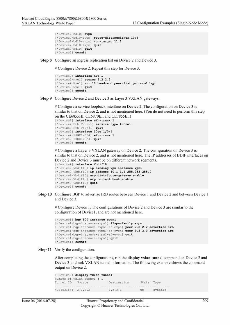
[*Device2-bd10] evpn[*Device2-bd10-evpn] route-distinguisher 10:1[*Device2-bd10-evpn] vpn-target 11:1[*Device2-bd10-evpn] quit[*Device2-bd10] quit[*Device2] commit
Step 8 Configure an ingress replication list on Device 2 and Device 3.
# Configure Device 2. Repeat this step for Device 3.
[~Device2] interface nve 1[*Device2-Nve1] source 2.2.2.2[*Device2-Nve1] vni 10 head-end peer-list protocol bgp[*Device2-Nve1] quit[*Device2] commit
Step 9 Configure Device 2 and Device 3 as Layer 3 VXLAN gateways.
# Configure a service loopback interface on Device 2. The configuration on Device 3 issimilar to that on Device 2, and is not mentioned here. (You do not need to perform this stepon the CE6855HI, CE6870EI, and CE7855EI.)[~Device2] interface eth-trunk 1[*Device2-Eth-Trunk1] service type tunnel[*Device2-Eth-Trunk1] quit[*Device2] interface 10ge 1/0/4[*Device2-10GE1/0/4] eth-trunk 1[*Device2-10GE1/0/4] quit[*Device2] commit
# Configure a Layer 3 VXLAN gateway on Device 2. The configuration on Device 3 issimilar to that on Device 2, and is not mentioned here. The IP addresses of BDIF interfaces onDevice 2 and Device 3 must be on different network segments.[~Device2] interface Vbdif10[*Device2-Vbdif10] ip binding vpn-instance vpn1[*Device2-Vbdif10] ip address 10.1.1.1 255.255.255.0[*Device2-Vbdif10] arp distribute-gateway enable[*Device2-Vbdif10] arp collect host enable[*Device2-Vbdif10] quit[*Device2] commit
Step 10 Configure BGP to advertise IRB routes between Device 1 and Device 2 and between Device 1and Device 3.
# Configure Device 1. The configurations of Device 2 and Device 3 are similar to theconfiguration of Device1, and are not mentioned here.
[~Device1] bgp 100 instance evpn1[~Device1-bgp-instance-evpn1] l2vpn-family evpn[~Device1-bgp-instance-evpn1-af-evpn] peer 2.2.2.2 advertise irb[*Device1-bgp-instance-evpn1-af-evpn] peer 3.3.3.3 advertise irb[*Device1-bgp-instance-evpn1-af-evpn] quit[*Device1-bgp-instance-evpn1] quit[*Device1] commit
Step 11 Verify the configuration.
After completing the configurations, run the display vxlan tunnel command on Device 2 andDevice 3 to check VXLAN tunnel information. The following example shows the commandoutput on Device 2.
[~Device2] display vxlan tunnelNumber of vxlan tunnel : 1Tunnel ID Source Destination State Type--------------------------------------------------------------4026531841 2.2.2.2 3.3.3.3 up dynamic
Huawei CloudEngine 8800&7800&6800&5800 SeriesVXLAN Technology White Paper 12 Configuration Examples (Single-Node Mode)
Issue 06 (2016-07-28) Huawei Proprietary and ConfidentialCopyright © Huawei Technologies Co., Ltd.
209

VM1s on different servers can communicate.
----End
Configuration Filesl Device 1 configuration file
#sysname Device1#evpn-overlay enable#interface 10GE1/0/0 undo portswitch ip address 192.168.3.2 255.255.255.0#interface 10GE1/0/1 undo portswitch ip address 192.168.2.2 255.255.255.0#interface LoopBack0 ip address 1.1.1.1 255.255.255.255#bgp 100 peer 192.168.2.1 as-number 200 peer 192.168.3.1 as-number 300 # ipv4-family unicast network 1.1.1.1 255.255.255.255 peer 192.168.2.1 enable peer 192.168.3.1 enable#bgp 100 instance evpn1 peer 2.2.2.2 as-number 100 peer 2.2.2.2 connect-interface LoopBack0 peer 3.3.3.3 as-number 100 peer 3.3.3.3 connect-interface LoopBack0 # l2vpn-family evpn undo policy vpn-target peer 2.2.2.2 enable peer 2.2.2.2 advertise irb peer 2.2.2.2 reflect-client peer 3.3.3.3 enable peer 3.3.3.3 advertise irb peer 3.3.3.3 reflect-client#return
l Device 2 configuration file#sysname Device2#assign forward nvo3 acl extend enable //This command is required only on the CE6870EI.#ip tunnel mode vxlan //This command is required only on the CE6870EI.#evpn-overlay enable#ip vpn-instance vpn1 ipv4-family route-distinguisher 11:11 vpn-target 1:1 export-extcommunity vpn-target 11:1 export-extcommunity evpn vpn-target 1:1 import-extcommunity vpn-target 11:1 import-extcommunity evpn vxlan vni 5010
Huawei CloudEngine 8800&7800&6800&5800 SeriesVXLAN Technology White Paper 12 Configuration Examples (Single-Node Mode)
Issue 06 (2016-07-28) Huawei Proprietary and ConfidentialCopyright © Huawei Technologies Co., Ltd.
210
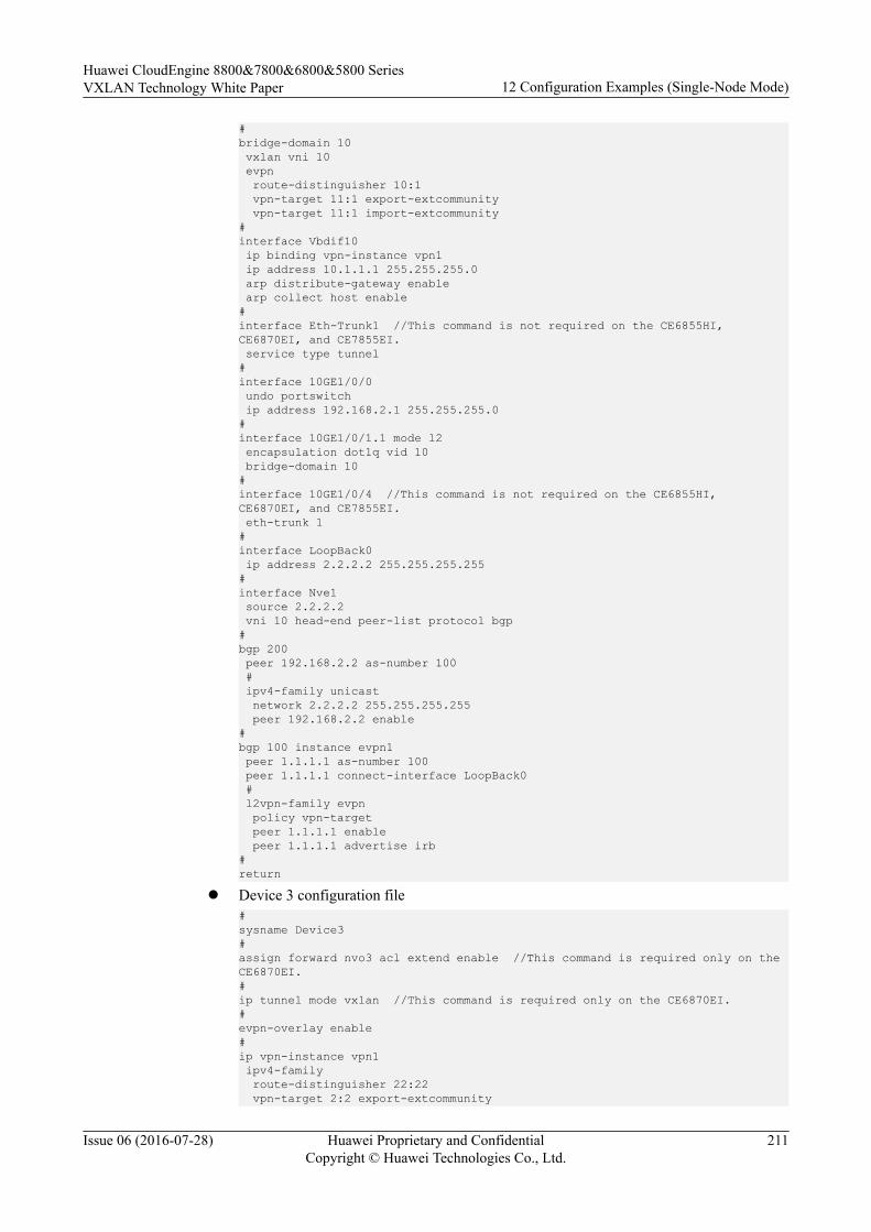
#bridge-domain 10 vxlan vni 10 evpn route-distinguisher 10:1 vpn-target 11:1 export-extcommunity vpn-target 11:1 import-extcommunity#interface Vbdif10 ip binding vpn-instance vpn1 ip address 10.1.1.1 255.255.255.0 arp distribute-gateway enable arp collect host enable#interface Eth-Trunk1 //This command is not required on the CE6855HI, CE6870EI, and CE7855EI. service type tunnel #interface 10GE1/0/0 undo portswitch ip address 192.168.2.1 255.255.255.0#interface 10GE1/0/1.1 mode l2 encapsulation dot1q vid 10 bridge-domain 10#interface 10GE1/0/4 //This command is not required on the CE6855HI, CE6870EI, and CE7855EI. eth-trunk 1 #interface LoopBack0 ip address 2.2.2.2 255.255.255.255#interface Nve1 source 2.2.2.2 vni 10 head-end peer-list protocol bgp#bgp 200 peer 192.168.2.2 as-number 100 # ipv4-family unicast network 2.2.2.2 255.255.255.255 peer 192.168.2.2 enable#bgp 100 instance evpn1 peer 1.1.1.1 as-number 100 peer 1.1.1.1 connect-interface LoopBack0 # l2vpn-family evpn policy vpn-target peer 1.1.1.1 enable peer 1.1.1.1 advertise irb#return
l Device 3 configuration file#sysname Device3#assign forward nvo3 acl extend enable //This command is required only on the CE6870EI.#ip tunnel mode vxlan //This command is required only on the CE6870EI.#evpn-overlay enable#ip vpn-instance vpn1 ipv4-family route-distinguisher 22:22 vpn-target 2:2 export-extcommunity
Huawei CloudEngine 8800&7800&6800&5800 SeriesVXLAN Technology White Paper 12 Configuration Examples (Single-Node Mode)
Issue 06 (2016-07-28) Huawei Proprietary and ConfidentialCopyright © Huawei Technologies Co., Ltd.
211
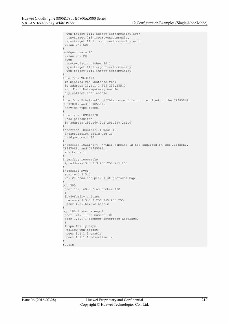
vpn-target 11:1 export-extcommunity evpn vpn-target 2:2 import-extcommunity vpn-target 11:1 import-extcommunity evpn vxlan vni 5010#bridge-domain 20 vxlan vni 20 evpn route-distinguisher 20:1 vpn-target 11:1 export-extcommunity vpn-target 11:1 import-extcommunity#interface Vbdif20 ip binding vpn-instance vpn1 ip address 20.1.1.1 255.255.255.0 arp distribute-gateway enable arp collect host enable#interface Eth-Trunk1 //This command is not required on the CE6855HI, CE6870EI, and CE7855EI. service type tunnel #interface 10GE1/0/0 undo portswitch ip address 192.168.3.1 255.255.255.0#interface 10GE1/0/1.1 mode l2 encapsulation dot1q vid 20 bridge-domain 20#interface 10GE1/0/4 //This command is not required on the CE6855HI, CE6870EI, and CE7855EI. eth-trunk 1 #interface LoopBack0 ip address 3.3.3.3 255.255.255.255#interface Nve1 source 3.3.3.3 vni 20 head-end peer-list protocol bgp#bgp 300 peer 192.168.3.2 as-number 100 # ipv4-family unicast network 3.3.3.3 255.255.255.255 peer 192.168.3.2 enable#bgp 100 instance evpn1 peer 1.1.1.1 as-number 100 peer 1.1.1.1 connect-interface LoopBack0 # l2vpn-family evpn policy vpn-target peer 1.1.1.1 enable peer 1.1.1.1 advertise irb#return
Huawei CloudEngine 8800&7800&6800&5800 SeriesVXLAN Technology White Paper 12 Configuration Examples (Single-Node Mode)
Issue 06 (2016-07-28) Huawei Proprietary and ConfidentialCopyright © Huawei Technologies Co., Ltd.
212
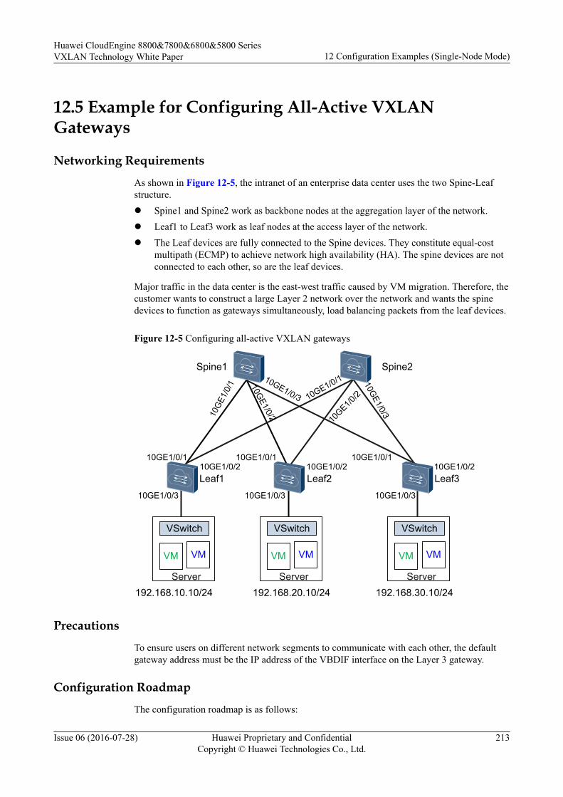
12.5 Example for Configuring All-Active VXLANGateways
Networking Requirements
As shown in Figure 12-5, the intranet of an enterprise data center uses the two Spine-Leafstructure.l Spine1 and Spine2 work as backbone nodes at the aggregation layer of the network.l Leaf1 to Leaf3 work as leaf nodes at the access layer of the network.l The Leaf devices are fully connected to the Spine devices. They constitute equal-cost
multipath (ECMP) to achieve network high availability (HA). The spine devices are notconnected to each other, so are the leaf devices.
Major traffic in the data center is the east-west traffic caused by VM migration. Therefore, thecustomer wants to construct a large Layer 2 network over the network and wants the spinedevices to function as gateways simultaneously, load balancing packets from the leaf devices.
Figure 12-5 Configuring all-active VXLAN gateways
10G
E1/0
/1
192.168.10.10/24
Spine1
VM VM
VSwitch
Server192.168.20.10/24 192.168.30.10/24
VM VM
VSwitch
Server
VM VM
VSwitch
Server
Spine2
Leaf1 Leaf2 Leaf3
10GE1/0/2
10GE1/0/3
10GE1/0/110GE1/0/2 10GE1/0/2 10GE1/0/2
10GE1/0/1 10GE1/0/1
10GE1/0/3 10GE1/0/3 10GE1/0/3
10GE1/0/3
10GE1/0
/210GE1/0/1
Precautions
To ensure users on different network segments to communicate with each other, the defaultgateway address must be the IP address of the VBDIF interface on the Layer 3 gateway.
Configuration Roadmap
The configuration roadmap is as follows:
Huawei CloudEngine 8800&7800&6800&5800 SeriesVXLAN Technology White Paper 12 Configuration Examples (Single-Node Mode)
Issue 06 (2016-07-28) Huawei Proprietary and ConfidentialCopyright © Huawei Technologies Co., Ltd.
213
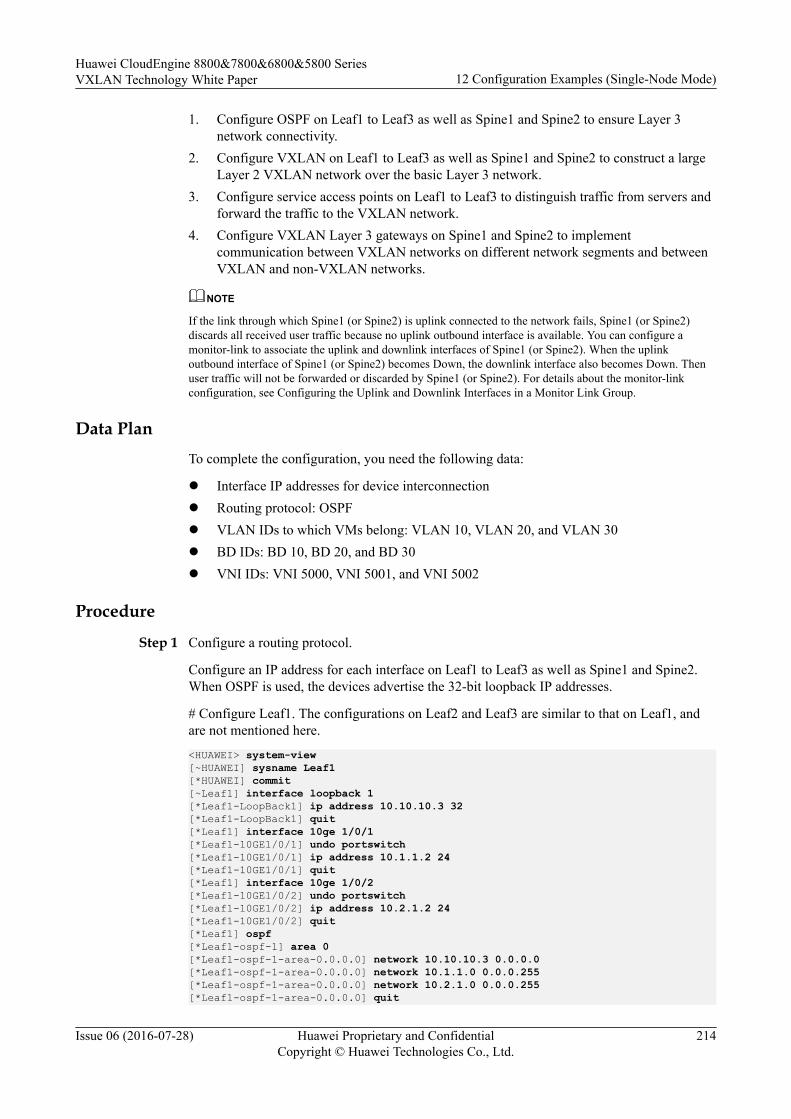
1. Configure OSPF on Leaf1 to Leaf3 as well as Spine1 and Spine2 to ensure Layer 3network connectivity.
2. Configure VXLAN on Leaf1 to Leaf3 as well as Spine1 and Spine2 to construct a largeLayer 2 VXLAN network over the basic Layer 3 network.
3. Configure service access points on Leaf1 to Leaf3 to distinguish traffic from servers andforward the traffic to the VXLAN network.
4. Configure VXLAN Layer 3 gateways on Spine1 and Spine2 to implementcommunication between VXLAN networks on different network segments and betweenVXLAN and non-VXLAN networks.
NOTE
If the link through which Spine1 (or Spine2) is uplink connected to the network fails, Spine1 (or Spine2)discards all received user traffic because no uplink outbound interface is available. You can configure amonitor-link to associate the uplink and downlink interfaces of Spine1 (or Spine2). When the uplinkoutbound interface of Spine1 (or Spine2) becomes Down, the downlink interface also becomes Down. Thenuser traffic will not be forwarded or discarded by Spine1 (or Spine2). For details about the monitor-linkconfiguration, see Configuring the Uplink and Downlink Interfaces in a Monitor Link Group.
Data PlanTo complete the configuration, you need the following data:
l Interface IP addresses for device interconnectionl Routing protocol: OSPFl VLAN IDs to which VMs belong: VLAN 10, VLAN 20, and VLAN 30l BD IDs: BD 10, BD 20, and BD 30l VNI IDs: VNI 5000, VNI 5001, and VNI 5002
Procedure
Step 1 Configure a routing protocol.
Configure an IP address for each interface on Leaf1 to Leaf3 as well as Spine1 and Spine2.When OSPF is used, the devices advertise the 32-bit loopback IP addresses.
# Configure Leaf1. The configurations on Leaf2 and Leaf3 are similar to that on Leaf1, andare not mentioned here.
<HUAWEI> system-view[~HUAWEI] sysname Leaf1[*HUAWEI] commit[~Leaf1] interface loopback 1[*Leaf1-LoopBack1] ip address 10.10.10.3 32[*Leaf1-LoopBack1] quit[*Leaf1] interface 10ge 1/0/1 [*Leaf1-10GE1/0/1] undo portswitch[*Leaf1-10GE1/0/1] ip address 10.1.1.2 24[*Leaf1-10GE1/0/1] quit[*Leaf1] interface 10ge 1/0/2 [*Leaf1-10GE1/0/2] undo portswitch[*Leaf1-10GE1/0/2] ip address 10.2.1.2 24[*Leaf1-10GE1/0/2] quit[*Leaf1] ospf[*Leaf1-ospf-1] area 0[*Leaf1-ospf-1-area-0.0.0.0] network 10.10.10.3 0.0.0.0[*Leaf1-ospf-1-area-0.0.0.0] network 10.1.1.0 0.0.0.255[*Leaf1-ospf-1-area-0.0.0.0] network 10.2.1.0 0.0.0.255[*Leaf1-ospf-1-area-0.0.0.0] quit
Huawei CloudEngine 8800&7800&6800&5800 SeriesVXLAN Technology White Paper 12 Configuration Examples (Single-Node Mode)
Issue 06 (2016-07-28) Huawei Proprietary and ConfidentialCopyright © Huawei Technologies Co., Ltd.
214
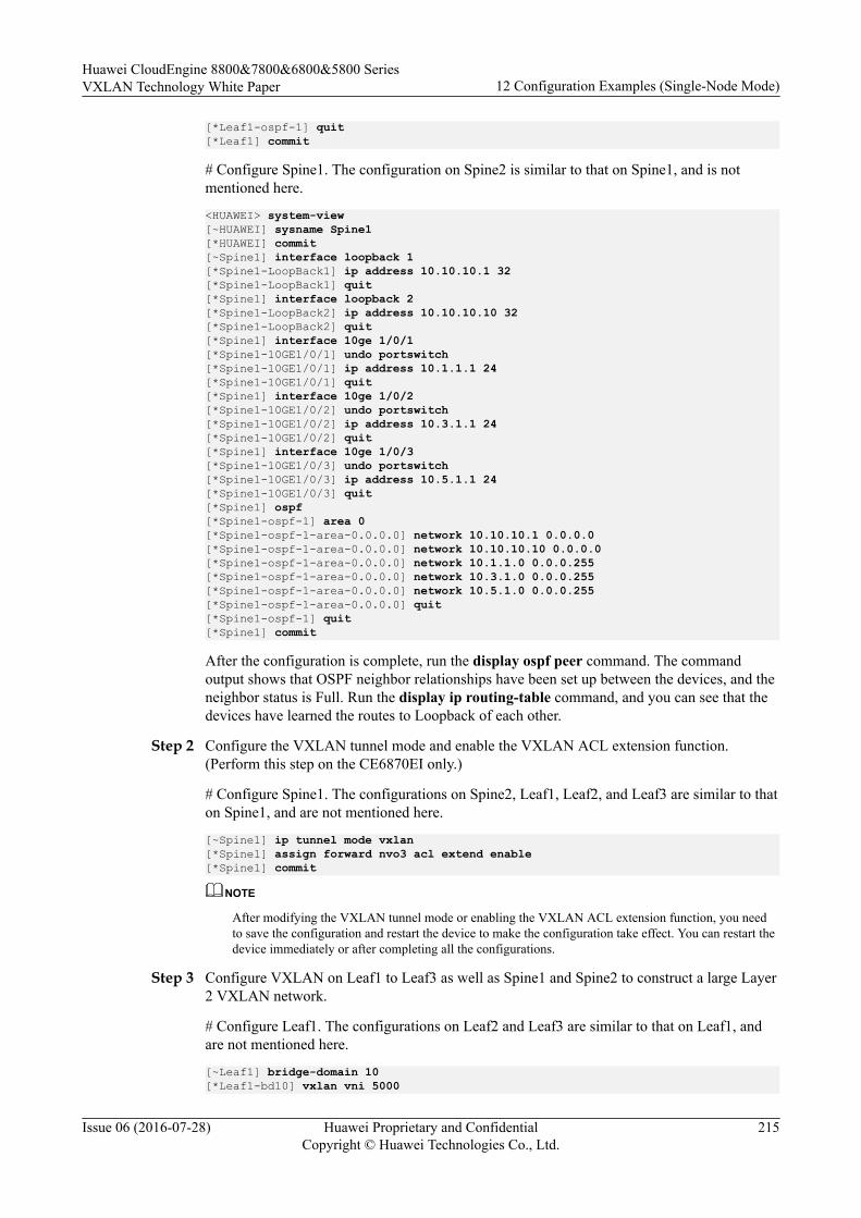
[*Leaf1-ospf-1] quit[*Leaf1] commit
# Configure Spine1. The configuration on Spine2 is similar to that on Spine1, and is notmentioned here.
<HUAWEI> system-view[~HUAWEI] sysname Spine1[*HUAWEI] commit[~Spine1] interface loopback 1[*Spine1-LoopBack1] ip address 10.10.10.1 32[*Spine1-LoopBack1] quit[*Spine1] interface loopback 2[*Spine1-LoopBack2] ip address 10.10.10.10 32[*Spine1-LoopBack2] quit[*Spine1] interface 10ge 1/0/1 [*Spine1-10GE1/0/1] undo portswitch[*Spine1-10GE1/0/1] ip address 10.1.1.1 24[*Spine1-10GE1/0/1] quit[*Spine1] interface 10ge 1/0/2 [*Spine1-10GE1/0/2] undo portswitch[*Spine1-10GE1/0/2] ip address 10.3.1.1 24[*Spine1-10GE1/0/2] quit[*Spine1] interface 10ge 1/0/3 [*Spine1-10GE1/0/3] undo portswitch[*Spine1-10GE1/0/3] ip address 10.5.1.1 24[*Spine1-10GE1/0/3] quit[*Spine1] ospf[*Spine1-ospf-1] area 0[*Spine1-ospf-1-area-0.0.0.0] network 10.10.10.1 0.0.0.0[*Spine1-ospf-1-area-0.0.0.0] network 10.10.10.10 0.0.0.0[*Spine1-ospf-1-area-0.0.0.0] network 10.1.1.0 0.0.0.255[*Spine1-ospf-1-area-0.0.0.0] network 10.3.1.0 0.0.0.255[*Spine1-ospf-1-area-0.0.0.0] network 10.5.1.0 0.0.0.255[*Spine1-ospf-1-area-0.0.0.0] quit[*Spine1-ospf-1] quit[*Spine1] commit
After the configuration is complete, run the display ospf peer command. The commandoutput shows that OSPF neighbor relationships have been set up between the devices, and theneighbor status is Full. Run the display ip routing-table command, and you can see that thedevices have learned the routes to Loopback of each other.
Step 2 Configure the VXLAN tunnel mode and enable the VXLAN ACL extension function.(Perform this step on the CE6870EI only.)
# Configure Spine1. The configurations on Spine2, Leaf1, Leaf2, and Leaf3 are similar to thaton Spine1, and are not mentioned here.
[~Spine1] ip tunnel mode vxlan[*Spine1] assign forward nvo3 acl extend enable[*Spine1] commit
NOTE
After modifying the VXLAN tunnel mode or enabling the VXLAN ACL extension function, you needto save the configuration and restart the device to make the configuration take effect. You can restart thedevice immediately or after completing all the configurations.
Step 3 Configure VXLAN on Leaf1 to Leaf3 as well as Spine1 and Spine2 to construct a large Layer2 VXLAN network.
# Configure Leaf1. The configurations on Leaf2 and Leaf3 are similar to that on Leaf1, andare not mentioned here.
[~Leaf1] bridge-domain 10[*Leaf1-bd10] vxlan vni 5000
Huawei CloudEngine 8800&7800&6800&5800 SeriesVXLAN Technology White Paper 12 Configuration Examples (Single-Node Mode)
Issue 06 (2016-07-28) Huawei Proprietary and ConfidentialCopyright © Huawei Technologies Co., Ltd.
215
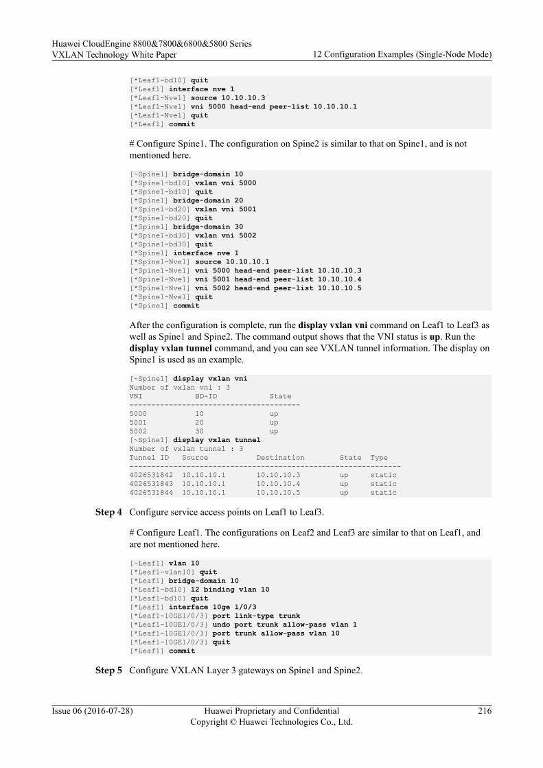
[*Leaf1-bd10] quit[*Leaf1] interface nve 1[*Leaf1-Nve1] source 10.10.10.3[*Leaf1-Nve1] vni 5000 head-end peer-list 10.10.10.1[*Leaf1-Nve1] quit[*Leaf1] commit
# Configure Spine1. The configuration on Spine2 is similar to that on Spine1, and is notmentioned here.
[~Spine1] bridge-domain 10[*Spine1-bd10] vxlan vni 5000[*Spine1-bd10] quit[*Spine1] bridge-domain 20[*Spine1-bd20] vxlan vni 5001[*Spine1-bd20] quit[*Spine1] bridge-domain 30[*Spine1-bd30] vxlan vni 5002[*Spine1-bd30] quit[*Spine1] interface nve 1[*Spine1-Nve1] source 10.10.10.1[*Spine1-Nve1] vni 5000 head-end peer-list 10.10.10.3[*Spine1-Nve1] vni 5001 head-end peer-list 10.10.10.4[*Spine1-Nve1] vni 5002 head-end peer-list 10.10.10.5[*Spine1-Nve1] quit[*Spine1] commit
After the configuration is complete, run the display vxlan vni command on Leaf1 to Leaf3 aswell as Spine1 and Spine2. The command output shows that the VNI status is up. Run thedisplay vxlan tunnel command, and you can see VXLAN tunnel information. The display onSpine1 is used as an example.
[~Spine1] display vxlan vniNumber of vxlan vni : 3VNI BD-ID State---------------------------------------5000 10 up5001 20 up5002 30 up[~Spine1] display vxlan tunnelNumber of vxlan tunnel : 3Tunnel ID Source Destination State Type--------------------------------------------------------------4026531842 10.10.10.1 10.10.10.3 up static4026531843 10.10.10.1 10.10.10.4 up static4026531844 10.10.10.1 10.10.10.5 up static
Step 4 Configure service access points on Leaf1 to Leaf3.
# Configure Leaf1. The configurations on Leaf2 and Leaf3 are similar to that on Leaf1, andare not mentioned here.
[~Leaf1] vlan 10[*Leaf1-vlan10] quit[*Leaf1] bridge-domain 10[*Leaf1-bd10] l2 binding vlan 10[*Leaf1-bd10] quit[*Leaf1] interface 10ge 1/0/3[*Leaf1-10GE1/0/3] port link-type trunk[*Leaf1-10GE1/0/3] undo port trunk allow-pass vlan 1[*Leaf1-10GE1/0/3] port trunk allow-pass vlan 10[*Leaf1-10GE1/0/3] quit[*Leaf1] commit
Step 5 Configure VXLAN Layer 3 gateways on Spine1 and Spine2.
Huawei CloudEngine 8800&7800&6800&5800 SeriesVXLAN Technology White Paper 12 Configuration Examples (Single-Node Mode)
Issue 06 (2016-07-28) Huawei Proprietary and ConfidentialCopyright © Huawei Technologies Co., Ltd.
216
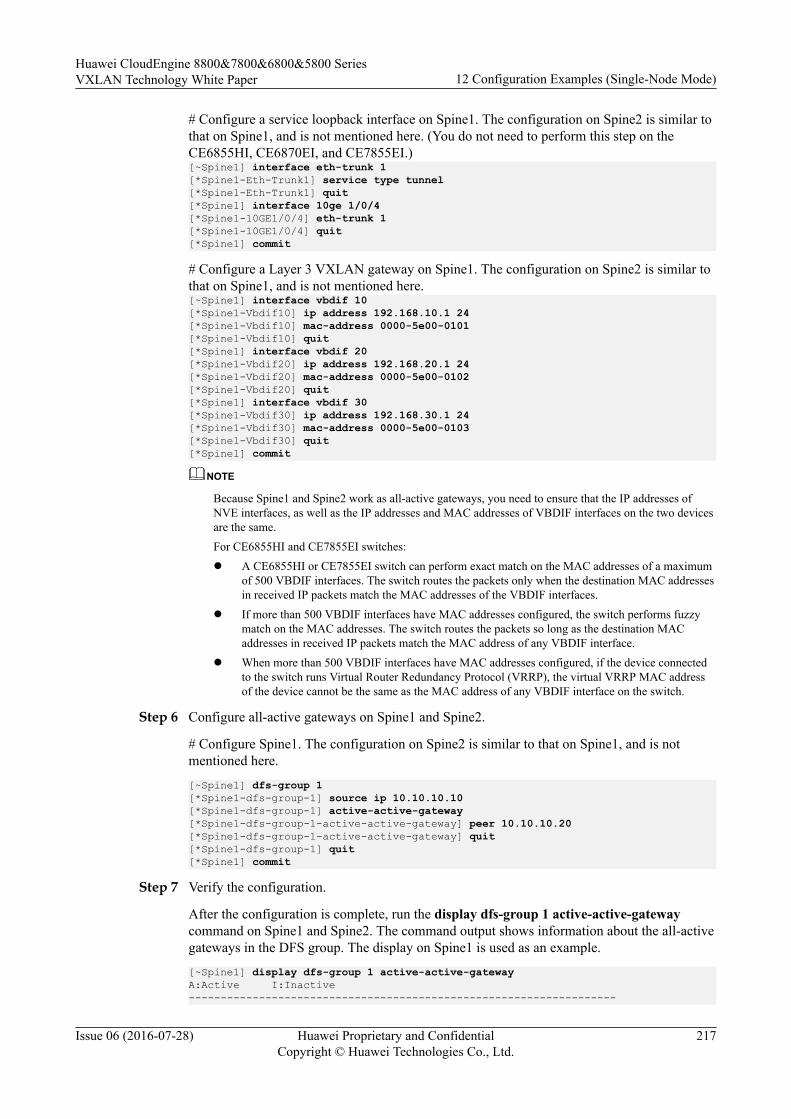
# Configure a service loopback interface on Spine1. The configuration on Spine2 is similar tothat on Spine1, and is not mentioned here. (You do not need to perform this step on theCE6855HI, CE6870EI, and CE7855EI.)[~Spine1] interface eth-trunk 1[*Spine1-Eth-Trunk1] service type tunnel[*Spine1-Eth-Trunk1] quit[*Spine1] interface 10ge 1/0/4[*Spine1-10GE1/0/4] eth-trunk 1[*Spine1-10GE1/0/4] quit[*Spine1] commit
# Configure a Layer 3 VXLAN gateway on Spine1. The configuration on Spine2 is similar tothat on Spine1, and is not mentioned here.[~Spine1] interface vbdif 10[*Spine1-Vbdif10] ip address 192.168.10.1 24[*Spine1-Vbdif10] mac-address 0000-5e00-0101[*Spine1-Vbdif10] quit[*Spine1] interface vbdif 20[*Spine1-Vbdif20] ip address 192.168.20.1 24[*Spine1-Vbdif20] mac-address 0000-5e00-0102[*Spine1-Vbdif20] quit[*Spine1] interface vbdif 30[*Spine1-Vbdif30] ip address 192.168.30.1 24[*Spine1-Vbdif30] mac-address 0000-5e00-0103[*Spine1-Vbdif30] quit[*Spine1] commit
NOTE
Because Spine1 and Spine2 work as all-active gateways, you need to ensure that the IP addresses ofNVE interfaces, as well as the IP addresses and MAC addresses of VBDIF interfaces on the two devicesare the same.For CE6855HI and CE7855EI switches:l A CE6855HI or CE7855EI switch can perform exact match on the MAC addresses of a maximum
of 500 VBDIF interfaces. The switch routes the packets only when the destination MAC addressesin received IP packets match the MAC addresses of the VBDIF interfaces.
l If more than 500 VBDIF interfaces have MAC addresses configured, the switch performs fuzzymatch on the MAC addresses. The switch routes the packets so long as the destination MACaddresses in received IP packets match the MAC address of any VBDIF interface.
l When more than 500 VBDIF interfaces have MAC addresses configured, if the device connectedto the switch runs Virtual Router Redundancy Protocol (VRRP), the virtual VRRP MAC addressof the device cannot be the same as the MAC address of any VBDIF interface on the switch.
Step 6 Configure all-active gateways on Spine1 and Spine2.
# Configure Spine1. The configuration on Spine2 is similar to that on Spine1, and is notmentioned here.
[~Spine1] dfs-group 1 [*Spine1-dfs-group-1] source ip 10.10.10.10[*Spine1-dfs-group-1] active-active-gateway [*Spine1-dfs-group-1-active-active-gateway] peer 10.10.10.20[*Spine1-dfs-group-1-active-active-gateway] quit[*Spine1-dfs-group-1] quit[*Spine1] commit
Step 7 Verify the configuration.
After the configuration is complete, run the display dfs-group 1 active-active-gatewaycommand on Spine1 and Spine2. The command output shows information about the all-activegateways in the DFS group. The display on Spine1 is used as an example.
[~Spine1] display dfs-group 1 active-active-gatewayA:Active I:Inactive -------------------------------------------------------------------
Huawei CloudEngine 8800&7800&6800&5800 SeriesVXLAN Technology White Paper 12 Configuration Examples (Single-Node Mode)
Issue 06 (2016-07-28) Huawei Proprietary and ConfidentialCopyright © Huawei Technologies Co., Ltd.
217

Peer System name State Duration 10.10.10.20 Spine2 A 0:0:8
----End
Configuration Filesl Configuration file of Leaf1
#sysname Leaf1#assign forward nvo3 acl extend enable //This command is required only on the CE6870EI.#vlan batch 10#ip tunnel mode vxlan //This command is required only on the CE6870EI.#bridge-domain 10 l2 binding vlan 10 vxlan vni 5000#interface 10GE1/0/1 undo portswitch ip address 10.1.1.2 255.255.255.0#interface 10GE1/0/2 undo portswitch ip address 10.2.1.2 255.255.255.0#interface 10GE1/0/3 port link-type trunk undo port trunk allow-pass vlan 1 port trunk allow-pass vlan 10#interface LoopBack1 ip address 10.10.10.3 255.255.255.255#interface Nve1 source 10.10.10.3 vni 5000 head-end peer-list 10.10.10.1#ospf 1 area 0.0.0.0 network 10.1.1.0 0.0.0.255 network 10.2.1.0 0.0.0.255 network 10.10.10.3 0.0.0.0#return
l Configuration file of Leaf2#sysname Leaf2#assign forward nvo3 acl extend enable //This command is required only on the CE6870EI.#vlan batch 20#ip tunnel mode vxlan //This command is required only on the CE6870EI.#bridge-domain 20 l2 binding vlan 20 vxlan vni 5001#interface 10GE1/0/1 undo portswitch ip address 10.3.1.2 255.255.255.0
Huawei CloudEngine 8800&7800&6800&5800 SeriesVXLAN Technology White Paper 12 Configuration Examples (Single-Node Mode)
Issue 06 (2016-07-28) Huawei Proprietary and ConfidentialCopyright © Huawei Technologies Co., Ltd.
218
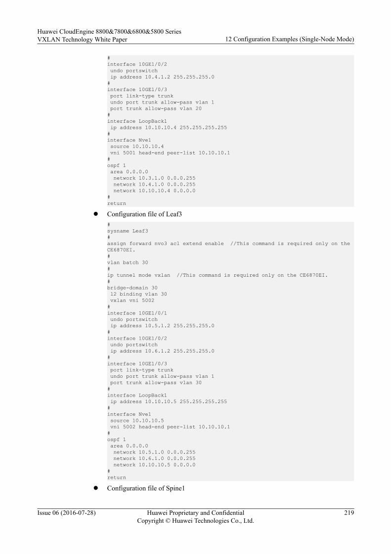
#interface 10GE1/0/2 undo portswitch ip address 10.4.1.2 255.255.255.0#interface 10GE1/0/3 port link-type trunk undo port trunk allow-pass vlan 1 port trunk allow-pass vlan 20#interface LoopBack1 ip address 10.10.10.4 255.255.255.255#interface Nve1 source 10.10.10.4 vni 5001 head-end peer-list 10.10.10.1#ospf 1 area 0.0.0.0 network 10.3.1.0 0.0.0.255 network 10.4.1.0 0.0.0.255 network 10.10.10.4 0.0.0.0#return
l Configuration file of Leaf3#sysname Leaf3#assign forward nvo3 acl extend enable //This command is required only on the CE6870EI.#vlan batch 30#ip tunnel mode vxlan //This command is required only on the CE6870EI.#bridge-domain 30 l2 binding vlan 30 vxlan vni 5002#interface 10GE1/0/1 undo portswitch ip address 10.5.1.2 255.255.255.0#interface 10GE1/0/2 undo portswitch ip address 10.6.1.2 255.255.255.0#interface 10GE1/0/3 port link-type trunk undo port trunk allow-pass vlan 1 port trunk allow-pass vlan 30#interface LoopBack1 ip address 10.10.10.5 255.255.255.255#interface Nve1 source 10.10.10.5 vni 5002 head-end peer-list 10.10.10.1#ospf 1 area 0.0.0.0 network 10.5.1.0 0.0.0.255 network 10.6.1.0 0.0.0.255 network 10.10.10.5 0.0.0.0#return
l Configuration file of Spine1
Huawei CloudEngine 8800&7800&6800&5800 SeriesVXLAN Technology White Paper 12 Configuration Examples (Single-Node Mode)
Issue 06 (2016-07-28) Huawei Proprietary and ConfidentialCopyright © Huawei Technologies Co., Ltd.
219
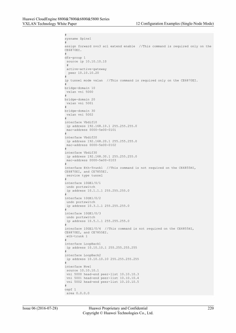
#sysname Spine1#assign forward nvo3 acl extend enable //This command is required only on the CE6870EI.#dfs-group 1 source ip 10.10.10.10 # active-active-gateway peer 10.10.10.20 #ip tunnel mode vxlan //This command is required only on the CE6870EI.# bridge-domain 10 vxlan vni 5000#bridge-domain 20 vxlan vni 5001#bridge-domain 30 vxlan vni 5002#interface Vbdif10 ip address 192.168.10.1 255.255.255.0 mac-address 0000-5e00-0101#interface Vbdif20 ip address 192.168.20.1 255.255.255.0 mac-address 0000-5e00-0102#interface Vbdif30 ip address 192.168.30.1 255.255.255.0 mac-address 0000-5e00-0103#interface Eth-Trunk1 //This command is not required on the CE6855HI, CE6870EI, and CE7855EI. service type tunnel #interface 10GE1/0/1 undo portswitch ip address 10.1.1.1 255.255.255.0#interface 10GE1/0/2 undo portswitch ip address 10.3.1.1 255.255.255.0#interface 10GE1/0/3 undo portswitch ip address 10.5.1.1 255.255.255.0#interface 10GE1/0/4 //This command is not required on the CE6855HI, CE6870EI, and CE7855EI. eth-trunk 1#interface LoopBack1 ip address 10.10.10.1 255.255.255.255#interface LoopBack2 ip address 10.10.10.10 255.255.255.255#interface Nve1 source 10.10.10.1 vni 5000 head-end peer-list 10.10.10.3 vni 5001 head-end peer-list 10.10.10.4 vni 5002 head-end peer-list 10.10.10.5#ospf 1 area 0.0.0.0
Huawei CloudEngine 8800&7800&6800&5800 SeriesVXLAN Technology White Paper 12 Configuration Examples (Single-Node Mode)
Issue 06 (2016-07-28) Huawei Proprietary and ConfidentialCopyright © Huawei Technologies Co., Ltd.
220
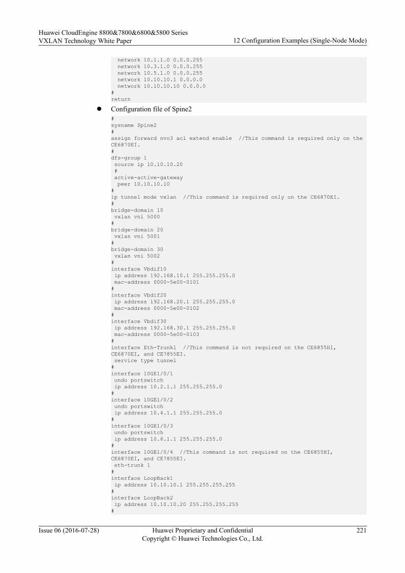
network 10.1.1.0 0.0.0.255 network 10.3.1.0 0.0.0.255 network 10.5.1.0 0.0.0.255 network 10.10.10.1 0.0.0.0 network 10.10.10.10 0.0.0.0#return
l Configuration file of Spine2#sysname Spine2#assign forward nvo3 acl extend enable //This command is required only on the CE6870EI.#dfs-group 1 source ip 10.10.10.20 # active-active-gateway peer 10.10.10.10 #ip tunnel mode vxlan //This command is required only on the CE6870EI.# bridge-domain 10 vxlan vni 5000#bridge-domain 20 vxlan vni 5001#bridge-domain 30 vxlan vni 5002#interface Vbdif10 ip address 192.168.10.1 255.255.255.0 mac-address 0000-5e00-0101#interface Vbdif20 ip address 192.168.20.1 255.255.255.0 mac-address 0000-5e00-0102#interface Vbdif30 ip address 192.168.30.1 255.255.255.0 mac-address 0000-5e00-0103#interface Eth-Trunk1 //This command is not required on the CE6855HI, CE6870EI, and CE7855EI. service type tunnel #interface 10GE1/0/1 undo portswitch ip address 10.2.1.1 255.255.255.0#interface 10GE1/0/2 undo portswitch ip address 10.4.1.1 255.255.255.0#interface 10GE1/0/3 undo portswitch ip address 10.6.1.1 255.255.255.0#interface 10GE1/0/4 //This command is not required on the CE6855HI, CE6870EI, and CE7855EI. eth-trunk 1#interface LoopBack1 ip address 10.10.10.1 255.255.255.255#interface LoopBack2 ip address 10.10.10.20 255.255.255.255#
Huawei CloudEngine 8800&7800&6800&5800 SeriesVXLAN Technology White Paper 12 Configuration Examples (Single-Node Mode)
Issue 06 (2016-07-28) Huawei Proprietary and ConfidentialCopyright © Huawei Technologies Co., Ltd.
221

interface Nve1 source 10.10.10.1 vni 5000 head-end peer-list 10.10.10.3 vni 5001 head-end peer-list 10.10.10.4 vni 5002 head-end peer-list 10.10.10.5#ospf 1 area 0.0.0.0 network 10.2.1.0 0.0.0.255 network 10.4.1.0 0.0.0.255 network 10.6.1.0 0.0.0.255 network 10.10.10.1 0.0.0.0 network 10.10.10.20 0.0.0.0#return
12.6 Example for Configuring Dual-Active VXLAN Access
Networking Requirements
The network shown in Figure 12-6 has the following requirements when servers access theVXLAN network:l To ensure high reliability, the server is dual-homed to two leaf devices. When one access
link fails, traffic can be rapidly switched to the other link.l To improve bandwidth utilization, two links are in active state simultaneously to load
balance traffic.
Figure 12-6 VXLAN dual-active access networking
VXLANNetwork
CE
M-LAG
Peer-link 110GE1/0/1 10GE1/0/1
10GE1/0/2 10GE1/0/310GE1/0/4
10GE1/0/5
10GE1/0/210GE1/0/310GE1/0/4
10GE1/0/5Leaf1 Leaf2
10GE1/0/1~10GE1/0/4Eth-Trunk 20
Eth-Trunk 10 Eth-Trunk 10
Spine110GE1/0/1 10GE1/0/2
Configuration Roadmap
The configuration roadmap is as follows:
1. Configure a routing protocol on Leaf1, Leaf2, and Spine1 to ensure Layer 3 networkconnectivity.
Huawei CloudEngine 8800&7800&6800&5800 SeriesVXLAN Technology White Paper 12 Configuration Examples (Single-Node Mode)
Issue 06 (2016-07-28) Huawei Proprietary and ConfidentialCopyright © Huawei Technologies Co., Ltd.
222
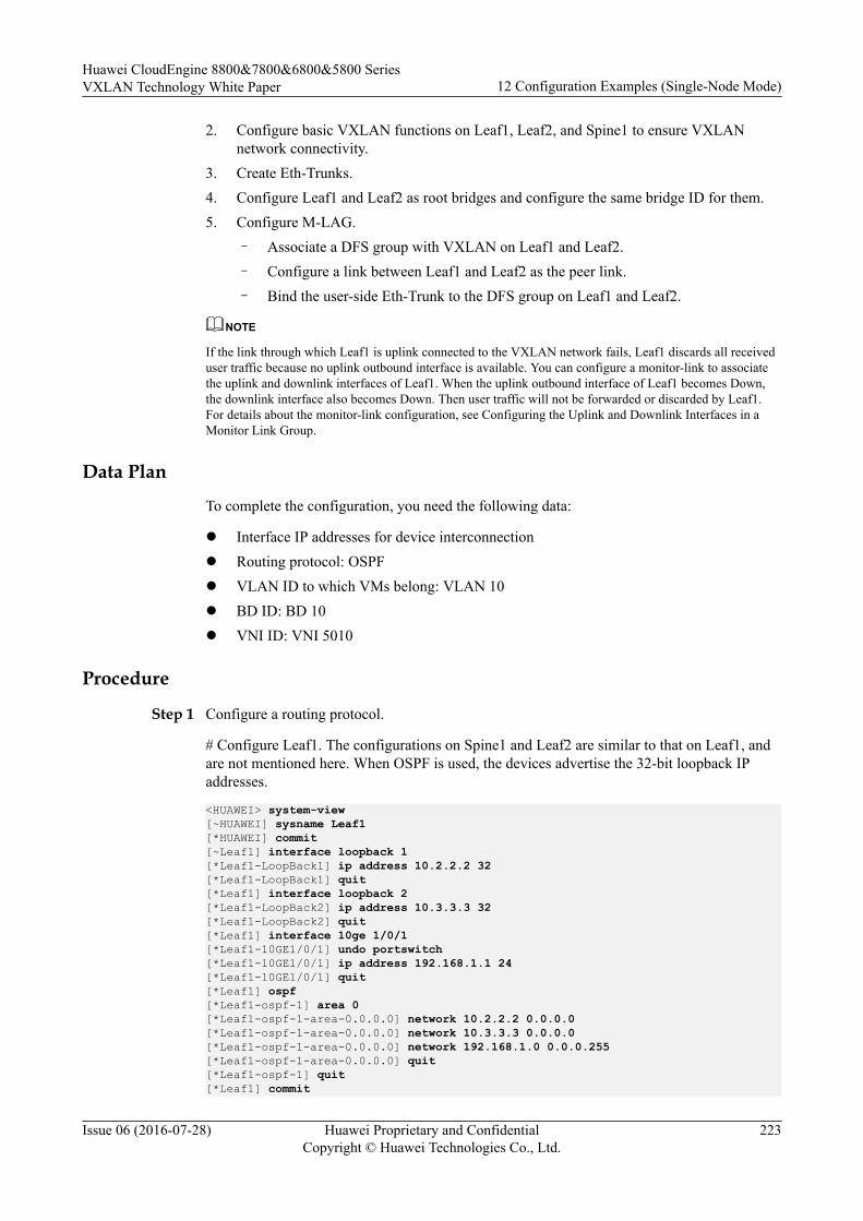
2. Configure basic VXLAN functions on Leaf1, Leaf2, and Spine1 to ensure VXLANnetwork connectivity.
3. Create Eth-Trunks.4. Configure Leaf1 and Leaf2 as root bridges and configure the same bridge ID for them.5. Configure M-LAG.
– Associate a DFS group with VXLAN on Leaf1 and Leaf2.– Configure a link between Leaf1 and Leaf2 as the peer link.– Bind the user-side Eth-Trunk to the DFS group on Leaf1 and Leaf2.
NOTE
If the link through which Leaf1 is uplink connected to the VXLAN network fails, Leaf1 discards all receiveduser traffic because no uplink outbound interface is available. You can configure a monitor-link to associatethe uplink and downlink interfaces of Leaf1. When the uplink outbound interface of Leaf1 becomes Down,the downlink interface also becomes Down. Then user traffic will not be forwarded or discarded by Leaf1.For details about the monitor-link configuration, see Configuring the Uplink and Downlink Interfaces in aMonitor Link Group.
Data Plan
To complete the configuration, you need the following data:
l Interface IP addresses for device interconnectionl Routing protocol: OSPFl VLAN ID to which VMs belong: VLAN 10l BD ID: BD 10l VNI ID: VNI 5010
Procedure
Step 1 Configure a routing protocol.
# Configure Leaf1. The configurations on Spine1 and Leaf2 are similar to that on Leaf1, andare not mentioned here. When OSPF is used, the devices advertise the 32-bit loopback IPaddresses.
<HUAWEI> system-view[~HUAWEI] sysname Leaf1[*HUAWEI] commit[~Leaf1] interface loopback 1[*Leaf1-LoopBack1] ip address 10.2.2.2 32[*Leaf1-LoopBack1] quit[*Leaf1] interface loopback 2[*Leaf1-LoopBack2] ip address 10.3.3.3 32[*Leaf1-LoopBack2] quit[*Leaf1] interface 10ge 1/0/1[*Leaf1-10GE1/0/1] undo portswitch[*Leaf1-10GE1/0/1] ip address 192.168.1.1 24[*Leaf1-10GE1/0/1] quit[*Leaf1] ospf[*Leaf1-ospf-1] area 0[*Leaf1-ospf-1-area-0.0.0.0] network 10.2.2.2 0.0.0.0[*Leaf1-ospf-1-area-0.0.0.0] network 10.3.3.3 0.0.0.0[*Leaf1-ospf-1-area-0.0.0.0] network 192.168.1.0 0.0.0.255[*Leaf1-ospf-1-area-0.0.0.0] quit[*Leaf1-ospf-1] quit[*Leaf1] commit
Huawei CloudEngine 8800&7800&6800&5800 SeriesVXLAN Technology White Paper 12 Configuration Examples (Single-Node Mode)
Issue 06 (2016-07-28) Huawei Proprietary and ConfidentialCopyright © Huawei Technologies Co., Ltd.
223
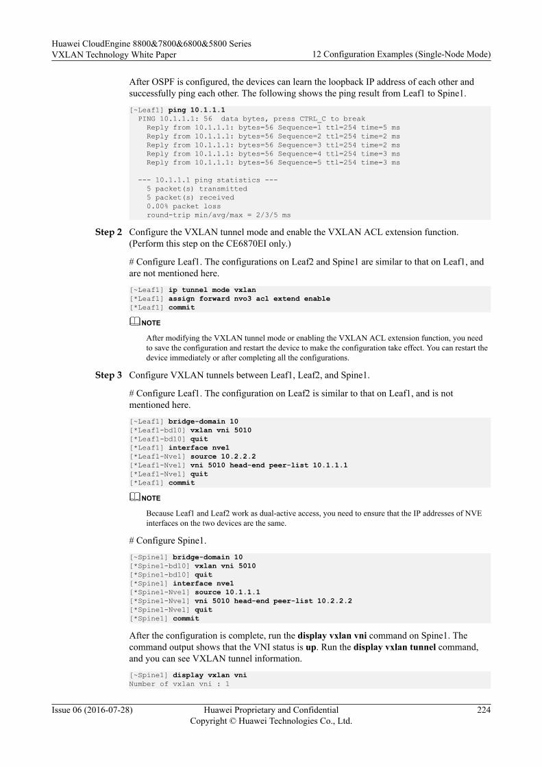
After OSPF is configured, the devices can learn the loopback IP address of each other andsuccessfully ping each other. The following shows the ping result from Leaf1 to Spine1.[~Leaf1] ping 10.1.1.1 PING 10.1.1.1: 56 data bytes, press CTRL_C to break Reply from 10.1.1.1: bytes=56 Sequence=1 ttl=254 time=5 ms Reply from 10.1.1.1: bytes=56 Sequence=2 ttl=254 time=2 ms Reply from 10.1.1.1: bytes=56 Sequence=3 ttl=254 time=2 ms Reply from 10.1.1.1: bytes=56 Sequence=4 ttl=254 time=3 ms Reply from 10.1.1.1: bytes=56 Sequence=5 ttl=254 time=3 ms
--- 10.1.1.1 ping statistics --- 5 packet(s) transmitted 5 packet(s) received 0.00% packet loss round-trip min/avg/max = 2/3/5 ms
Step 2 Configure the VXLAN tunnel mode and enable the VXLAN ACL extension function.(Perform this step on the CE6870EI only.)
# Configure Leaf1. The configurations on Leaf2 and Spine1 are similar to that on Leaf1, andare not mentioned here.[~Leaf1] ip tunnel mode vxlan[*Leaf1] assign forward nvo3 acl extend enable[*Leaf1] commit
NOTE
After modifying the VXLAN tunnel mode or enabling the VXLAN ACL extension function, you needto save the configuration and restart the device to make the configuration take effect. You can restart thedevice immediately or after completing all the configurations.
Step 3 Configure VXLAN tunnels between Leaf1, Leaf2, and Spine1.
# Configure Leaf1. The configuration on Leaf2 is similar to that on Leaf1, and is notmentioned here.[~Leaf1] bridge-domain 10[*Leaf1-bd10] vxlan vni 5010[*Leaf1-bd10] quit[*Leaf1] interface nve1[*Leaf1-Nve1] source 10.2.2.2[*Leaf1-Nve1] vni 5010 head-end peer-list 10.1.1.1[*Leaf1-Nve1] quit[*Leaf1] commit
NOTE
Because Leaf1 and Leaf2 work as dual-active access, you need to ensure that the IP addresses of NVEinterfaces on the two devices are the same.
# Configure Spine1.[~Spine1] bridge-domain 10[*Spine1-bd10] vxlan vni 5010[*Spine1-bd10] quit[*Spine1] interface nve1[*Spine1-Nve1] source 10.1.1.1[*Spine1-Nve1] vni 5010 head-end peer-list 10.2.2.2[*Spine1-Nve1] quit[*Spine1] commit
After the configuration is complete, run the display vxlan vni command on Spine1. Thecommand output shows that the VNI status is up. Run the display vxlan tunnel command,and you can see VXLAN tunnel information.[~Spine1] display vxlan vniNumber of vxlan vni : 1
Huawei CloudEngine 8800&7800&6800&5800 SeriesVXLAN Technology White Paper 12 Configuration Examples (Single-Node Mode)
Issue 06 (2016-07-28) Huawei Proprietary and ConfidentialCopyright © Huawei Technologies Co., Ltd.
224
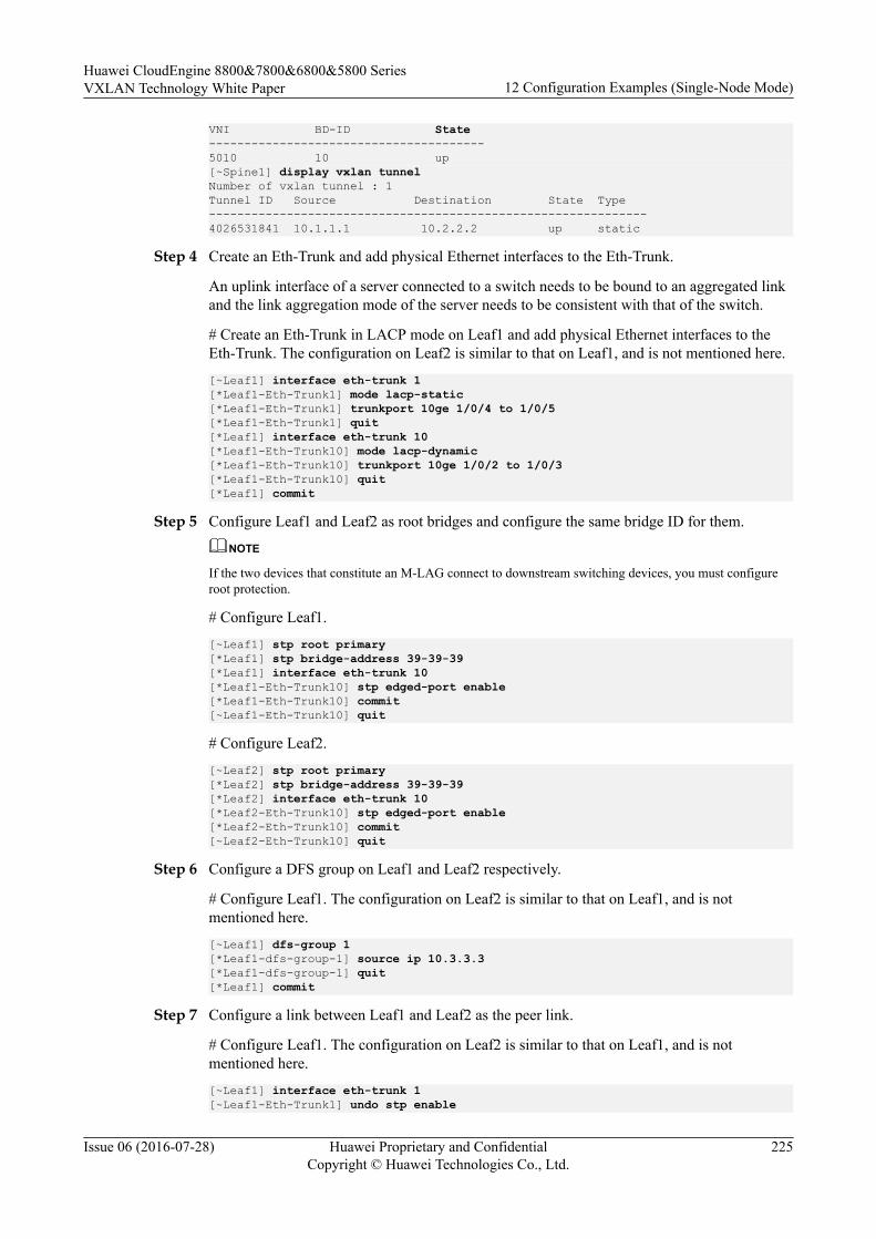
VNI BD-ID State---------------------------------------5010 10 up[~Spine1] display vxlan tunnelNumber of vxlan tunnel : 1Tunnel ID Source Destination State Type--------------------------------------------------------------4026531841 10.1.1.1 10.2.2.2 up static
Step 4 Create an Eth-Trunk and add physical Ethernet interfaces to the Eth-Trunk.
An uplink interface of a server connected to a switch needs to be bound to an aggregated linkand the link aggregation mode of the server needs to be consistent with that of the switch.
# Create an Eth-Trunk in LACP mode on Leaf1 and add physical Ethernet interfaces to theEth-Trunk. The configuration on Leaf2 is similar to that on Leaf1, and is not mentioned here.
[~Leaf1] interface eth-trunk 1[*Leaf1-Eth-Trunk1] mode lacp-static[*Leaf1-Eth-Trunk1] trunkport 10ge 1/0/4 to 1/0/5[*Leaf1-Eth-Trunk1] quit[*Leaf1] interface eth-trunk 10[*Leaf1-Eth-Trunk10] mode lacp-dynamic[*Leaf1-Eth-Trunk10] trunkport 10ge 1/0/2 to 1/0/3[*Leaf1-Eth-Trunk10] quit[*Leaf1] commit
Step 5 Configure Leaf1 and Leaf2 as root bridges and configure the same bridge ID for them.
NOTE
If the two devices that constitute an M-LAG connect to downstream switching devices, you must configureroot protection.
# Configure Leaf1.
[~Leaf1] stp root primary[*Leaf1] stp bridge-address 39-39-39[*Leaf1] interface eth-trunk 10[*Leaf1-Eth-Trunk10] stp edged-port enable[*Leaf1-Eth-Trunk10] commit[~Leaf1-Eth-Trunk10] quit
# Configure Leaf2.
[~Leaf2] stp root primary[*Leaf2] stp bridge-address 39-39-39[*Leaf2] interface eth-trunk 10[*Leaf2-Eth-Trunk10] stp edged-port enable[*Leaf2-Eth-Trunk10] commit[~Leaf2-Eth-Trunk10] quit
Step 6 Configure a DFS group on Leaf1 and Leaf2 respectively.
# Configure Leaf1. The configuration on Leaf2 is similar to that on Leaf1, and is notmentioned here.
[~Leaf1] dfs-group 1[*Leaf1-dfs-group-1] source ip 10.3.3.3[*Leaf1-dfs-group-1] quit[*Leaf1] commit
Step 7 Configure a link between Leaf1 and Leaf2 as the peer link.
# Configure Leaf1. The configuration on Leaf2 is similar to that on Leaf1, and is notmentioned here.
[~Leaf1] interface eth-trunk 1[~Leaf1-Eth-Trunk1] undo stp enable
Huawei CloudEngine 8800&7800&6800&5800 SeriesVXLAN Technology White Paper 12 Configuration Examples (Single-Node Mode)
Issue 06 (2016-07-28) Huawei Proprietary and ConfidentialCopyright © Huawei Technologies Co., Ltd.
225
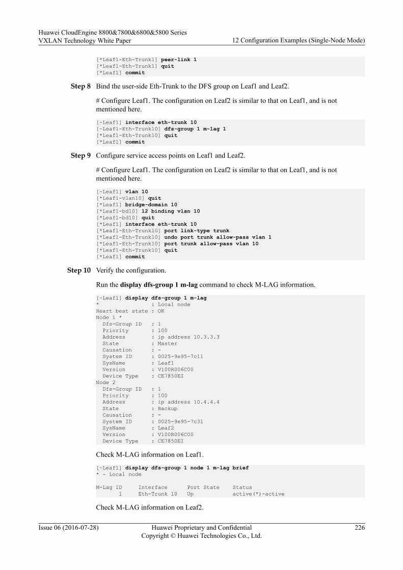
[*Leaf1-Eth-Trunk1] peer-link 1[*Leaf1-Eth-Trunk1] quit[*Leaf1] commit
Step 8 Bind the user-side Eth-Trunk to the DFS group on Leaf1 and Leaf2.
# Configure Leaf1. The configuration on Leaf2 is similar to that on Leaf1, and is notmentioned here.
[~Leaf1] interface eth-trunk 10[~Leaf1-Eth-Trunk10] dfs-group 1 m-lag 1[*Leaf1-Eth-Trunk10] quit[*Leaf1] commit
Step 9 Configure service access points on Leaf1 and Leaf2.
# Configure Leaf1. The configuration on Leaf2 is similar to that on Leaf1, and is notmentioned here.
[~Leaf1] vlan 10[*Leaf1-vlan10] quit[*Leaf1] bridge-domain 10[*Leaf1-bd10] l2 binding vlan 10[*Leaf1-bd10] quit[*Leaf1] interface eth-trunk 10[*Leaf1-Eth-Trunk10] port link-type trunk[*Leaf1-Eth-Trunk10] undo port trunk allow-pass vlan 1[*Leaf1-Eth-Trunk10] port trunk allow-pass vlan 10[*Leaf1-Eth-Trunk10] quit[*Leaf1] commit
Step 10 Verify the configuration.
Run the display dfs-group 1 m-lag command to check M-LAG information.
[~Leaf1] display dfs-group 1 m-lag* : Local nodeHeart beat state : OKNode 1 * Dfs-Group ID : 1 Priority : 100 Address : ip address 10.3.3.3 State : Master Causation : - System ID : 0025-9e95-7c11 SysName : Leaf1 Version : V100R006C00 Device Type : CE7850EINode 2 Dfs-Group ID : 1 Priority : 100 Address : ip address 10.4.4.4 State : Backup Causation : - System ID : 0025-9e95-7c31 SysName : Leaf2 Version : V100R006C00 Device Type : CE7850EI
Check M-LAG information on Leaf1.
[~Leaf1] display dfs-group 1 node 1 m-lag brief* - Local node
M-Lag ID Interface Port State Status 1 Eth-Trunk 10 Up active(*)-active
Check M-LAG information on Leaf2.
Huawei CloudEngine 8800&7800&6800&5800 SeriesVXLAN Technology White Paper 12 Configuration Examples (Single-Node Mode)
Issue 06 (2016-07-28) Huawei Proprietary and ConfidentialCopyright © Huawei Technologies Co., Ltd.
226
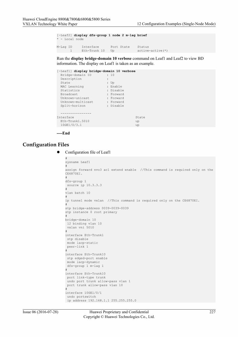
[~Leaf2] display dfs-group 1 node 2 m-lag brief* - Local node
M-Lag ID Interface Port State Status 1 Eth-Trunk 10 Up active-active(*)
Run the display bridge-domain 10 verbose command on Leaf1 and Leaf2 to view BDinformation. The display on Leaf1 is taken as an example.
[~Leaf1] display bridge-domain 10 verbose Bridge-domain ID : 10 Description : State : Up MAC Learning : Enable Statistics : Disable Broadcast : Forward Unknown-unicast : Forward Unknown-multicast : Forward Split-horizon : Disable ----------------Interface State Eth-Trunk1.5010 up 10GE1/0/3.1 up
----End
Configuration Filesl Configuration file of Leaf1
#sysname Leaf1#assign forward nvo3 acl extend enable //This command is required only on the CE6870EI.#dfs-group 1 source ip 10.3.3.3 #vlan batch 10#ip tunnel mode vxlan //This command is required only on the CE6870EI.#stp bridge-address 0039-0039-0039stp instance 0 root primary#bridge-domain 10 l2 binding vlan 10 vxlan vni 5010 # interface Eth-Trunk1 stp disable mode lacp-static peer-link 1 # interface Eth-Trunk10 stp edged-port enable mode lacp-dynamic dfs-group 1 m-lag 1 #interface Eth-Trunk10 port link-type trunk undo port trunk allow-pass vlan 1 port trunk allow-pass vlan 10# interface 10GE1/0/1 undo portswitch ip address 192.168.1.1 255.255.255.0
Huawei CloudEngine 8800&7800&6800&5800 SeriesVXLAN Technology White Paper 12 Configuration Examples (Single-Node Mode)
Issue 06 (2016-07-28) Huawei Proprietary and ConfidentialCopyright © Huawei Technologies Co., Ltd.
227
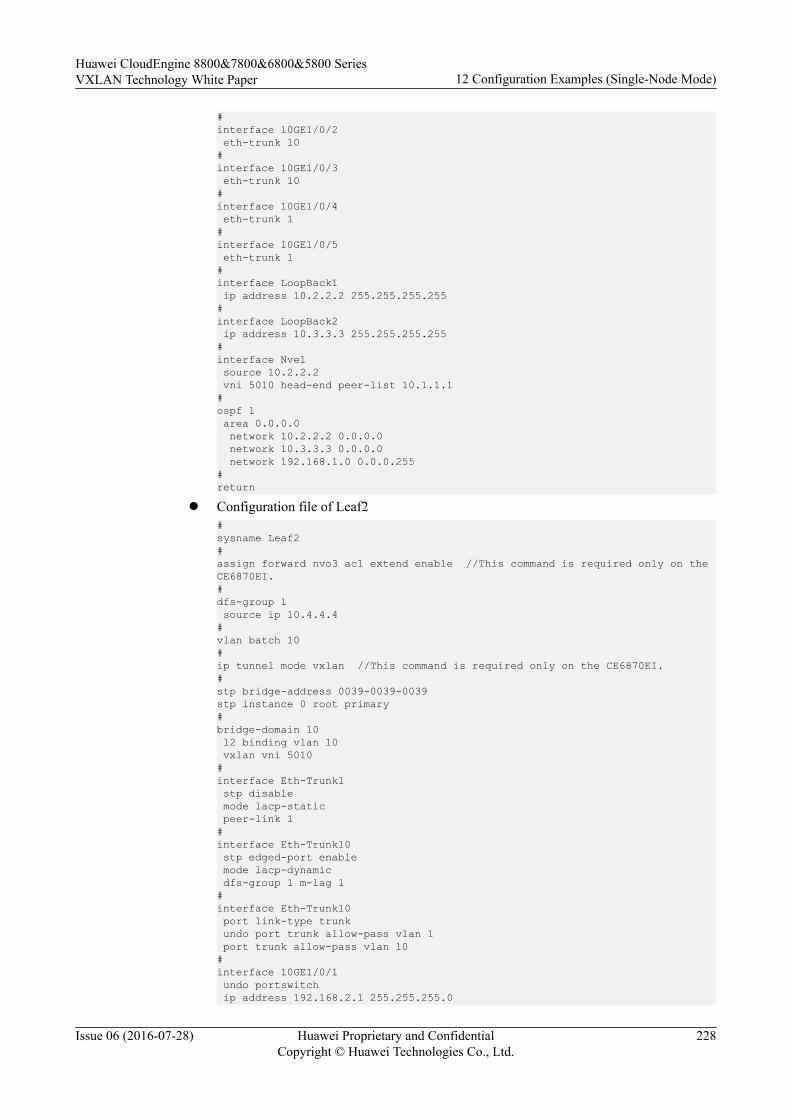
#interface 10GE1/0/2 eth-trunk 10#interface 10GE1/0/3 eth-trunk 10#interface 10GE1/0/4 eth-trunk 1#interface 10GE1/0/5 eth-trunk 1#interface LoopBack1 ip address 10.2.2.2 255.255.255.255#interface LoopBack2 ip address 10.3.3.3 255.255.255.255#interface Nve1 source 10.2.2.2 vni 5010 head-end peer-list 10.1.1.1# ospf 1 area 0.0.0.0 network 10.2.2.2 0.0.0.0 network 10.3.3.3 0.0.0.0 network 192.168.1.0 0.0.0.255#return
l Configuration file of Leaf2#sysname Leaf2#assign forward nvo3 acl extend enable //This command is required only on the CE6870EI.# dfs-group 1 source ip 10.4.4.4 #vlan batch 10#ip tunnel mode vxlan //This command is required only on the CE6870EI.#stp bridge-address 0039-0039-0039stp instance 0 root primary#bridge-domain 10 l2 binding vlan 10 vxlan vni 5010 # interface Eth-Trunk1 stp disable mode lacp-static peer-link 1 # interface Eth-Trunk10 stp edged-port enable mode lacp-dynamic dfs-group 1 m-lag 1 #interface Eth-Trunk10 port link-type trunk undo port trunk allow-pass vlan 1 port trunk allow-pass vlan 10# interface 10GE1/0/1 undo portswitch ip address 192.168.2.1 255.255.255.0
Huawei CloudEngine 8800&7800&6800&5800 SeriesVXLAN Technology White Paper 12 Configuration Examples (Single-Node Mode)
Issue 06 (2016-07-28) Huawei Proprietary and ConfidentialCopyright © Huawei Technologies Co., Ltd.
228
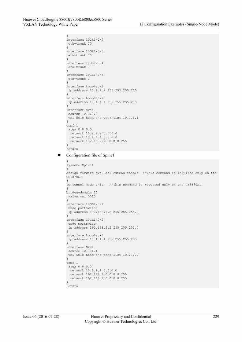
#interface 10GE1/0/2 eth-trunk 10#interface 10GE1/0/3 eth-trunk 10#interface 10GE1/0/4 eth-trunk 1#interface 10GE1/0/5 eth-trunk 1#interface LoopBack1 ip address 10.2.2.2 255.255.255.255#interface LoopBack2 ip address 10.4.4.4 255.255.255.255#interface Nve1 source 10.2.2.2 vni 5010 head-end peer-list 10.1.1.1# ospf 1 area 0.0.0.0 network 10.2.2.2 0.0.0.0 network 10.4.4.4 0.0.0.0 network 192.168.2.0 0.0.0.255#return
l Configuration file of Spine1#sysname Spine1#assign forward nvo3 acl extend enable //This command is required only on the CE6870EI.#ip tunnel mode vxlan //This command is required only on the CE6870EI.#bridge-domain 10 vxlan vni 5010#interface 10GE1/0/1 undo portswitch ip address 192.168.1.2 255.255.255.0#interface 10GE1/0/2 undo portswitch ip address 192.168.2.2 255.255.255.0#interface LoopBack1 ip address 10.1.1.1 255.255.255.255#interface Nve1 source 10.1.1.1 vni 5010 head-end peer-list 10.2.2.2#ospf 1 area 0.0.0.0 network 10.1.1.1 0.0.0.0 network 192.168.1.0 0.0.0.255 network 192.168.2.0 0.0.0.255#return
Huawei CloudEngine 8800&7800&6800&5800 SeriesVXLAN Technology White Paper 12 Configuration Examples (Single-Node Mode)
Issue 06 (2016-07-28) Huawei Proprietary and ConfidentialCopyright © Huawei Technologies Co., Ltd.
229

13 References
The following table lists the references.
Document No. Document Name Remarks
draft-ietf-bess-evpn-prefix-advertisement-01
IP Prefix Advertisement in EVPN -
draft-ietf-bess-evpn-inter-subnet-forwarding-00
Integrated Routing and Bridging in EVPN -
draft-ietf-NVo3-framework-04
Framework for DC Network Virtualization -
draft-ietf-NVo3-dataplane-requirements-02
NVo3 Data Plane Requirements -
draft-mahalingam-dutt-dcops-vxlan-06
A Framework for Overlaying Virtualized Layer2 Networks over Layer 3 Networks
-
RFC 7432 BGP MPLS-Based Ethernet VPN -
Huawei CloudEngine 8800&7800&6800&5800 SeriesVXLAN Technology White Paper 13 References
Issue 06 (2016-07-28) Huawei Proprietary and ConfidentialCopyright © Huawei Technologies Co., Ltd.
230