
VULCANISING PROCEDURE - International Conveyors · Experience Woven with technology VULCANISING...
18
Experience Woven with technology VULCANISING PROCEDURE SOLID WOVEN PVC CONVEYOR BELTING • PVC Covers • Nitrile Covers • Neoprene Covers
Transcript of VULCANISING PROCEDURE - International Conveyors · Experience Woven with technology VULCANISING...
Experience Woven with technology
VULCANISING PROCEDURE
SOLID WOVEN PVC CONVEYOR BELTING
• PVC Covers• Nitrile Covers• Neoprene Covers

CONTENTS
1) SCOPE 2
2) CONDITIONS OF WORKPLACE 2
3) TOOLS AND EQUIPMENT REQUIRED 3
4) FINGER SPLICE DIMENSIONS 4
5) SPLICING MATERIALS TO BE USED 5
6) PREPARATION OF BREAKER FABRIC 6
7) PREPARATION OF FINGER SPLICE – CUSTOM ASSEMBLY 7
8) CURING METHOD 9
9) INSPECTION OF THE FINISHED SPLICE 11
10) IDENTIFICATION MARKINGS OF THE SPLICE 11
11) CONTACT DETAILS 12
APPENDIX A: INSPECTION CHECKLIST 13
APPENDIX B: SPECIAL INSTRUCTIONS FOR NEOPRENE COVERED BELTS 16
APPENDIX C: SPLICE RECORD SHEET 17
1
1 SCOPE
This procedure details the requirements for hot vulcanizing of solid woven belts with PVC, Nitrile
and Neoprene covers and / or a combination of same, to make endless belts using finger-
splicing method.
The principle of this procedure shall be applied when splicing any belting made of solid woven
carcass and impregnated with fire resistant antistatic PVC compound; and more particularly for
ICL MINEPLAST fire resistant antistatic (FRAS) PVC conveyor belting as well as ICL Mineplast
belt with Nitrile or Neoprene covers.
Composition of FRAS compounds differs from one country to the other and also in between
surface and underground application conforming to the regulatory standard of each country.
Therefore, care shall be taken to ensure that proper compounds are used when undertaking any
splicing work on solid woven FRAS PVC belting.
The method of splicing described in these guidelines and the materials specified to be used
have been developed to ensure that a high strength, reliable joint is achieved. Further, for high
strength solid woven belts the finger method contained herein represent the preferred jointing
methodology for these bets
2 CONDITIONS OF WORKPLACE
A convenient workplace is a prerequisite for a good splice work. Preparing a suitable workspace
well before undertaking the actual work optimizes the total time required between the start and
end of the required work. The following conditions should be complied with:
a) The workplace must be dry and as dust free as possible. Degree of atmospheric moisture
and dust present at the workplace has a direct bearing on the quality and effectiveness of
adhesion.
b) Movement of air must be kept to a minimum.
c) The workplace must have adequate light to ensure a clear and safe working environment.
d) When working on a conveyor, a worktable to accommodate the press and a preparation
table is required. About 3 metres (10 feet) free space at both ends of the worktable is
recommended to allow correct alignment of the splice.
e) Compressed air supply (if required) for the vulcanizing press.
f) Suitable electrical supply and power points for the vulcanizing press.
g) Water recirculation for the vulcanizing press if it has a water-cooling facility.
h) Suitably rated clamps to restrain the belt during the complete procedure
i) If the work is proceeding on a live conveyor system, ensure the correct and complete
isolation procedures have been adhered to.
2

3 TOOLS & EQUIPMENT REQUIRED
a) White or yellow crayon pencil to draw datum and reference lines. b) Measuring Tape.
c) Blade Knives (e.g. fixed blade or Olfa knife).
d) Alligator Clamps with adequate cable pull. e) Vernier caliper for accurate measurement.
f) Hand brush.
g) Planer or slow speed rotary power tool with abrasive head.
h) Cutting tool for cutting splice fingers as an alternate to blade knife.
i) Spatula for spreading paste.
j) Scissors.
k) Vulcanizing Press complete with well calibrated electrical temperature and pressure controls,
pressure and water hoses as required with temperature and pressure indicators.
– Temperature accuracy ±3°C (±5°F)
– 689 kPa (100 psi) minimum pressure capacity
– Platten length = Splice length + 150mm or 6 inches (minimum)
– Platten width = Belt width + 150mm or 6 inches (minimum)
l) Two edge bars, approx. 100mm wide and 0.5-1mm thinner than the belt thickness, but
approx. 300mm longer than the press length.
m) Suitable clamping device for the type of Solid Woven belt (usually sash clamps).
n) Template for marking splice.
3
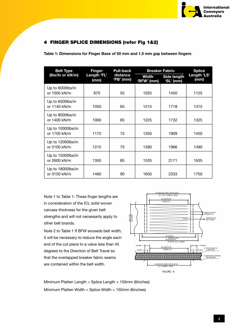
4 FINGER SPLICE DIMENSIONS (refer Fig 1&2)
Table 1: Dimensions for Finger Base of 50 mm and 1.5 mm gap between fingers
Note 1 to Table 1: These finger lengths are
in consideration of the ICL solid woven
carcass thickness for the given belt
strengths and will not necessarily apply to
other belt brands.
Note 2 to Table 1 If BFW exceeds belt width,
it will be necessary to reduce the angle each
end of the cut piece to a value less than 45
degrees to the Direction of Belt Travel so
that the overlapped breaker fabric seams
are contained within the belt width.
Minimum Platten Length = Splice Length + 150mm (6inches)
Minimum Platten Width = Splice Width + 150mm (6inches)
Up to 6000lbs/in or 1050 kN/m 870 55 1025 1450 1125
Up to 6500lbs/in or 1140 kN/m 1050 65 1215 1718 1315
Up to 8000lbs/in or 1400 kN/m 1060 65 1225 1732 1325
Up to 10000lbs/in or 1750 kN/m 1175 75 1350 1909 1450
Up to 12000lbs/in or 2100 kN/m 1215 75 1390 1966 1490
Up to 15000lbs/in or 2600 kN/m 1350 85 1535 2171 1635
Up to 18000lbs/in or 3150 kN/m 1460 90 1650 2333 1750
Belt Type (lbs/In or kN/m)
Finger Length ‘FL’
(mm)
Splice Length ‘LS’
(mm)
Pull-back distance ‘PB’ (mm)
Width ‘BFW’ (mm)
Side length ‘SL’ (mm)
Breaker Fabric
(F) BREAKER FABRIC WIDTH (BFW)(LF + PB + 100MM) = (BFW)
(E) LENGTH OF
(A) LENGTH
(E) LENGTH OF
(F) BREAKER FABRIC WIDTH (BFW)
(C) TOP COVER (TC) CARRY SIDE
100 MM
50 MM
100 MM
50 MM
(D) BOTTOM COVER (BC) RETURN SIDE
(LF + 100MM) = (BFW)
FIGURE - A
(B) LENGTH OFOF SPLICE. (LS)
FINGER. (LF)
PLATTEN. (LP) + 200MM
WIDTH OF EACHFINGER (W-F).
DIRECTION OFBELT TRAVEL
FINGER.(LF)
BELT (WB)
WID
TH O
F
4
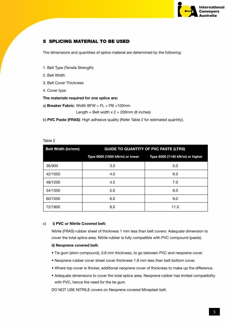
5 SPLICING MATERIAL TO BE USED
The dimensions and quantities of splice material are determined by the following:
1. Belt Type (Tensile Strength)
2. Belt Width
3. Belt Cover Thickness
4. Cover type
The materials required for one splice are:
a) Breaker Fabric: Width BFW = FL + PB +100mm
Length = Belt width x 2 + 200mm (8 inches)
b) PVC Paste (FRAS): High adhesive quality (Refer Table 2 for estimated quantity).
c)
Table 2
i) PVC or Nitrile Covered belt:
Nitrile (FRAS) rubber sheet of thickness 1 mm less than belt covers: Adequate dimension to
cover the total splice area. Nitrile rubber is fully compatible with PVC compound (paste).
ii) Neoprene covered belt:
• Tie gum (skim compound), 0.8 mm thickness, to go between PVC and neoprene cover.
• Neoprene rubber cover sheet cover thickness 1.8 mm less than belt bottom cover.
• Where top cover is thicker, additional neoprene cover of thickness to make up the difference.
• Adequate dimensions to cover the total splice area. Neoprene rubber has limited compatibility
with PVC, hence the need for the tie gum
DO NOT USE NITRILE covers on Neoprene covered Mineplast belt.
36/900 3.0 5.0
42/1050 4.0 6.0
48/1200 4.5 7.0
54/1350 5.0 8.0
60/1050 6.0 9.0
72/1800 8.0 11.0
Belt Width (in/mm)
Type 6000 (1050 kN/m) or lower Type 6500 (1140 kN/m) or higher
GUIDE TO QUANTITY OF PVC PASTE (LTRS)
5

d) Silicone Coated Paper (Release Paper): Width = Breaker Fabric Width + 100mm
Length = 2 x platten length + 50mm
e) Shelf life
i) PVC (FRAS) Paste: Maximum of 12 months if stored in a dry place, not exposed to direct
sunlight and within a temperature range between 5 – 20°C (41 – 68°F).
ii) Nitrile Rubber/Neoprene Cover Sheet: Maximum of 3 months if stored in a dry place, not
exposed to direct sunlight and within a temperature range between 5- 20°C.
iii) Materials can last longer if stored at 5°C in a cool room, but need to be checked once
exceeding the shelf life above
IMPORTANT: All materials must be clearly dated and batch marked with shelf life.
6 PREPARATION OF BREAKER FABRIC
Breaker Fabric is available in 1600 mm wide rolls and is required to be marked and cut prior
to use, as shown in Figure B. This ensures that the fabric is used on the bias, ie. The warp and
weft yarns are at 45° angles to that of the belt. For most standard belt strengths and widths, two
bias cut pieces will be required.
a. Start the process by drawing a 45° diagonal line across the fabric to provide a baseline from
which to work (Line ‘A’ to ‘B’ in Figure B).
b. Measure along one edge of the breaker fabric from the previously marked line at ‘A’ a
distance of SL = BFW x 1.42 to ‘C’ as per Table 1.
c. Thereafter, draw a line at 45° from point ‘C’ parallel to the baseline to point ‘D’.
d. Now cut along both lines to make the breaker fabric bias length as required.
NOTE WELL:
When the sides of the breaker fabric are folded over the top of the joint, the two edges should
overlap by about 50-100mm (2 – 4 inches):
A C E
B D F
AC
BD
PREPARATION/PROFILECUTTING OF BREAKER
FABRIC
LAYING OF BREAKERFABRIC ON CONVEYOR
BELTING FIGURE - B
BELT (WB)
WIDTH OF
1300MM
WID
E
45°
BREAKER FA
BRIC
6
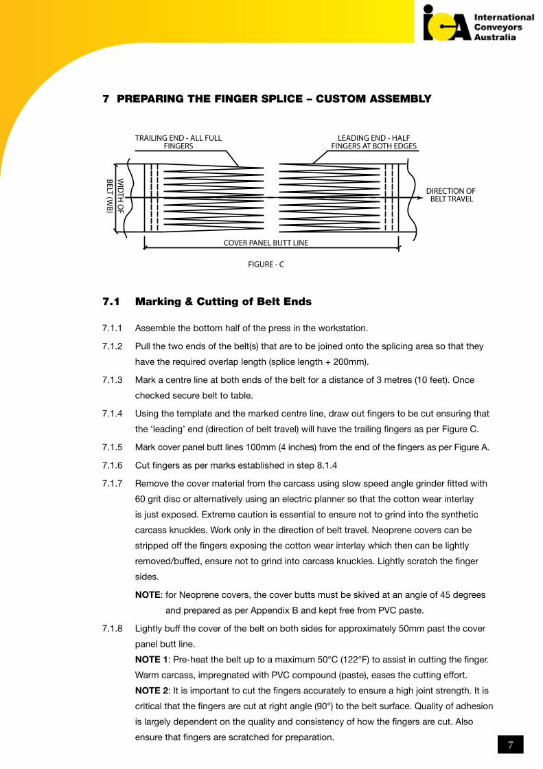
7 PREPARING THE FINGER SPLICE – CUSTOM ASSEMBLY
7.1 Marking & Cutting of Belt Ends
7.1.1 Assemble the bottom half of the press in the workstation.
7.1.2 Pull the two ends of the belt(s) that are to be joined onto the splicing area so that they
have the required overlap length (splice length + 200mm).
7.1.3 Mark a centre line at both ends of the belt for a distance of 3 metres (10 feet). Once
checked secure belt to table.
7.1.4 Using the template and the marked centre line, draw out fingers to be cut ensuring that
the ‘leading’ end (direction of belt travel) will have the trailing fingers as per Figure C.
7.1.5 Mark cover panel butt lines 100mm (4 inches) from the end of the fingers as per Figure A.
7.1.6 Cut fingers as per marks established in step 8.1.4
7.1.7 Remove the cover material from the carcass using slow speed angle grinder fitted with
60 grit disc or alternatively using an electric planner so that the cotton wear interlay
is just exposed. Extreme caution is essential to ensure not to grind into the synthetic
carcass knuckles. Work only in the direction of belt travel. Neoprene covers can be
stripped off the fingers exposing the cotton wear interlay which then can be lightly
removed/buffed, ensure not to grind into carcass knuckles. Lightly scratch the finger
sides.
NOTE: for Neoprene covers, the cover butts must be skived at an angle of 45 degrees
and prepared as per Appendix B and kept free from PVC paste.
7.1.8 Lightly buff the cover of the belt on both sides for approximately 50mm past the cover
panel butt line.
NOTE 1: Pre-heat the belt up to a maximum 50°C (122°F) to assist in cutting the finger.
Warm carcass, impregnated with PVC compound (paste), eases the cutting effort.
NOTE 2: It is important to cut the fingers accurately to ensure a high joint strength. It is
critical that the fingers are cut at right angle (90°) to the belt surface. Quality of adhesion
is largely dependent on the quality and consistency of how the fingers are cut. Also
ensure that fingers are scratched for preparation.
TRAILING END - ALL FULLFINGERS
COVER PANEL BUTT LINE
FIGURE - C
BELT (WB)
WID
TH O
F
DIRECTION OF BELT TRAVEL
LEADING END - HALFFINGERS AT BOTH EDGES
7
7.1.9 Arrange the fingers allowing a 1.5 mm gap between each finger and ensuring both ends
are correctly centred. The required 1.5mm gap is obtained by laying both ends down
with the additional Pull-Back distance per Table 1.between the two cover panel butt
lines.
7.1.10 Check alignment of the belt onto the preparation tables to ensure no movement. (via
string line).
7.2 Assembly of the Finger Splice
7.2.1 Mark the cover panel butt lines on the lower cooling plate.
7.2.2 Fold back each end of the splice and fasten. The splice area on top of the cooling plate
is now empty.
7.2.3 Heat bottom platten to approximately 40°C (104°F).
7.2.4 Lay release paper over the lower cooling plate.
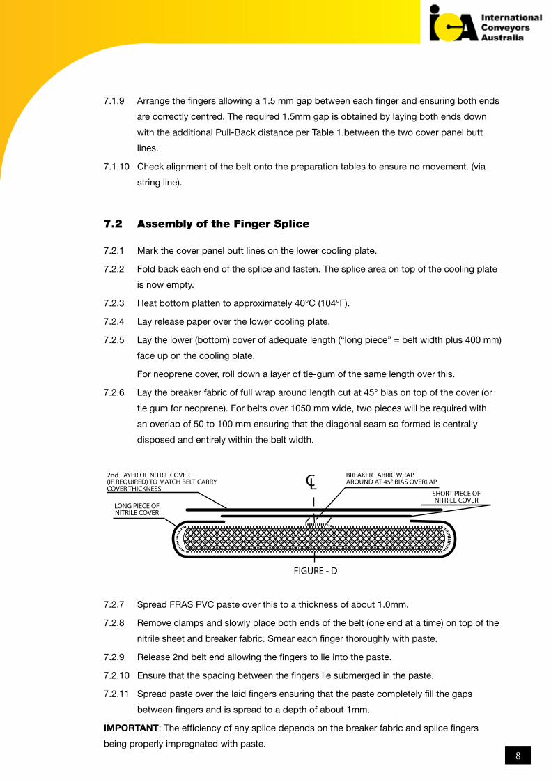
7.2.5 Lay the lower (bottom) cover of adequate length (“long piece” = belt width plus 400 mm)
face up on the cooling plate.
For neoprene cover, roll down a layer of tie-gum of the same length over this.
7.2.6 Lay the breaker fabric of full wrap around length cut at 45° bias on top of the cover (or
tie gum for neoprene). For belts over 1050 mm wide, two pieces will be required with
an overlap of 50 to 100 mm ensuring that the diagonal seam so formed is centrally
disposed and entirely within the belt width.
7.2.7 Spread FRAS PVC paste over this to a thickness of about 1.0mm.
7.2.8 Remove clamps and slowly place both ends of the belt (one end at a time) on top of the
nitrile sheet and breaker fabric. Smear each finger thoroughly with paste.
7.2.9 Release 2nd belt end allowing the fingers to lie into the paste.
7.2.10 Ensure that the spacing between the fingers lie submerged in the paste.
7.2.11 Spread paste over the laid fingers ensuring that the paste completely fill the gaps
between fingers and is spread to a depth of about 1mm.
IMPORTANT: The efficiency of any splice depends on the breaker fabric and splice fingers
being properly impregnated with paste.
CL2nd LAYER OF NITRIL COVER (IF REQUIRED) TO MATCH BELT CARRYCOVER THICKNESS
BREAKER FABRIC WRAPAROUND AT 45° BIAS OVERLAP
SHORT PIECE OFNITRILE COVER
LONG PIECE OFNITRILE COVER
FIGURE - D
8
7.2.13 Wrap the breaker fabric around edges up to the top centreline of the belt width. Keep
an overlap of 50 – 100mm (2 – 4 inches) and ensure that all the fingers from both ends
– leading and trailing – are closed together without squeezing out the paste around
the fingers or over-riding one another. Extreme care shall be taken to ensure this
compliance.
7.2.14 Spread FRAS paste on the edges and on the top of the wrapped around breaker fabric
to cover the interstices of the fabric as well as between the assemble fingers and the
breaker fabric.
7.2.15 Wrap the long cover over the splice edges and wrap around breaker fabric to at least
cover the outer fingers. This process will ensure fingers both ends of the belt sit side by
side (male-female) without uneven gaps between the two adjacent fingers or without any
over-ride.
7.2.16 For neoprene covered belts, prepare the shorter cover panel by rolling tie gum over the
pre-cut Neoprene cover.
Place the shorter cover on top of the paste (tie gum against the paste for neoprene)
submerged and wrapped around breaker fabric in the position as shown in Figure D and
trim to butt with the wrapped longer bottom panel. Ensure that there is adequate paste
between the breaker fabric and the nitrile sheet.
In cases where the top cover is thicker than the bottom, roll over a full width layer of
cover of the appropriate thickness
Note well: To ensure the PVC does not contaminate the skives, back off the paste by 4
to 5 mm during lay-up
7.2.17 Cover the entire splice with release paper.
7.2.18 Place and secure edge bars in the correct position adjacent to both edges of
the belt width.
7.2.19 Assemble top of the press, securely clamping edge bars with restraining devices to
prevent any movement of the spliced fingers during vulcanisation.
8 CURING METHOD
8.1 Assembling the curing process.
8.2 Pre-heat the press to 100 + 5°C (212°F) without applying the pressure.
8.3 Maintain the temperature at 100°C (212°F) for 10 minutes.
8.4 Then apply 690kPa (100 psi) pressure and simultaneously increase platten temperature
to 150°C (302°F). Make sure all platten heat evenly (+3°C). If necessary, manually
control the plattens.
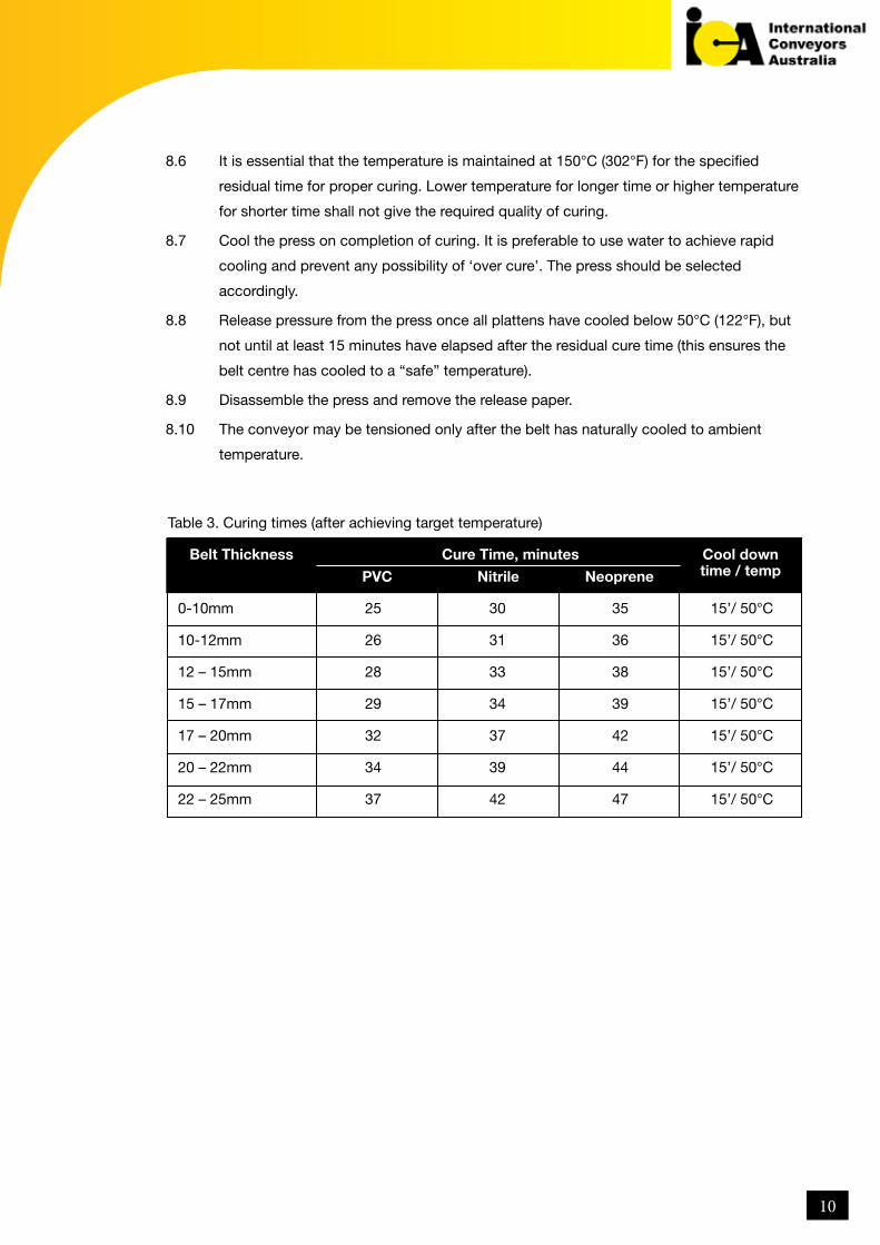
8.5 The residual cure time per Table 3 starts when the temperature of all platten sections
reaches 147°C. Maintain an even specified platten temperature within +3°C during the
curing process.
9
8.6 It is essential that the temperature is maintained at 150°C (302°F) for the specified
residual time for proper curing. Lower temperature for longer time or higher temperature
for shorter time shall not give the required quality of curing.
8.7 Cool the press on completion of curing. It is preferable to use water to achieve rapid
cooling and prevent any possibility of ‘over cure’. The press should be selected
accordingly.
8.8 Release pressure from the press once all plattens have cooled below 50°C (122°F), but
not until at least 15 minutes have elapsed after the residual cure time (this ensures the
belt centre has cooled to a “safe” temperature).
8.9 Disassemble the press and remove the release paper.
8.10 The conveyor may be tensioned only after the belt has naturally cooled to ambient
temperature.
Table 3. Curing times (after achieving target temperature)
0-10mm 25 30 35 15’/ 50°C
10-12mm 26 31 36 15’/ 50°C
12 – 15mm 28 33 38 15’/ 50°C
15 – 17mm 29 34 39 15’/ 50°C
17 – 20mm 32 37 42 15’/ 50°C
20 – 22mm 34 39 44 15’/ 50°C
22 – 25mm 37 42 47 15’/ 50°C
Belt Thickness Cool down time / temp PVC Nitrile Neoprene
Cure Time, minutes
10
9 INSPECTION OF THE FINISHED SPLICE
The splice must be inspected from all sides for any visual defects.
9.1 Any spewed PVC, Nitrile or Neoprene rubber shall be trimmed off.
9.2 Any overrun on the cover panel shall be removed by knife or buffing.
9.3 Check the alignment of the splice to the parent belt.
9.4 Check the relevant splice dimensions such as:
– Belt width immediately in front and behind the splice area.
– Belt thickness immediately in front and behind the splice area.
– Belt width at the splice area.
– Belt thickness at the splice area.
9.5 All results are to be recorded on the splice record sheet per Appendix D.
10 IDENTIFICATION MARKING OF THE SPLICE
10.1 Each splice shall be marked with a unique identification number. This number shall
give complete traceability of date splicing, equipment used, batch numbers of splicing
materials used, crew and vulcanising record sheets.
10.2 Marking shall be embossed onto the bottom cover of the splice, at least 1mm deep,
approximately 100mm (4 inches) inside from the edge of the belt, Letters should be
approximately 50mm (2 inches) high and clearly visible.
10.3 Where marking is not possible, the splice number and date should be neatly embossed
into the trailing portion of the belt end approximately 2 meters (6.5 feet) from the splice,
without damaging the belt carcass.
11
11 Contact Details
International Conveyors Limited
Corporate Office
10 Middleton Row,
Kolkata 700 071, India
Phone +91 33 2229 6033
Fax +91 33 2217 2269
Email [email protected]
Australia
International Conveyors Australia Pty Ltd.
Unit 24, 195 Prospect Highway
Seven Hills, NSW, 2147
Australia.
Tel: 1300 737 180
FAX: +61 2 4210 8810
www.internationalconveyors.com.au
ICL Works
E-39, M.I.D.C. Industrial Area
Chikalthana
Aurangabad 431 006
Maharashtra
India
Phone +91 240 248 5248 / 240 2485149
Fax+91 240 248 4358
Email [email protected]
North America
International Conveyors America Limited, Inc.
10 W State Street, Suite 108,
Geneva, IL 60134
Phone 630 549 4007
Email [email protected]
China
Visa Trading (Shanghai) Co. Ltd
Corporate office 2202, Hongjia Tower
388 Fushan Road Pudong
New Area Shanghai 200122
People’s Republic of China.
Phone +86 21 5015 9651 / 9652 / 9653
Fax + 86 21 5015 9650
Email [email protected]
Registered Office and Works I
Falta SEZ, Sector - 2, Near Pump House No. 3,
Village & Mouza - Akalmegh,
District - South 24 Parganas, West Bengal - 743 504
Email [email protected]
Works II
E-39, MIDC Industrial Area, Chikalthana,
Aurangabad 431 006, Maharashtra, India
Phone+91 240 248 5248/ 5149
Fax +91 240 248 4358
Email [email protected]
12

APPENDIX A – INSPECTION CHECKLIST
A–1: ARRANGEMENT
A–3: PREPARATION
A–2: ALIGNMENT
Approved QA plan available
Workstation suitable for splicing
Idler Rollers & Brackets adjacent to splice area removed
Top surface of bottom platten level with top of trough roller (if applicable)
Bottom platten edges parallel to the direction of belt travel
Wooden boards approximately 250mm (10 inches) wider than belt
Top surface of boards at same level as top surface of bottom press platten
Tables are stable to a minimum length of 3m (10ft)
Centre line established and fingers cut to diagram as per specification.
Fingers cut perpendicular to belt surface.
Splice leading end fingers outermost as per diagram.
Cover material removed from fingers using slow speed grinder or planner.
Carcass not over buffed or degraded.
Carcass lightly buffed for 50mm beyond cover panel butt line.
Both ends of the belt firmly clamped to preparation table (outside splice area).
Belt is lined up in either direction for a minimum distance of 3m (10ft)
Belt is central on the conveyor supporting rollers
Both ends overlap on the bottom platten
Overlap is adequate
Centre line is established in either direction for a minimum of 3m (10ft)
ARRANGEMENT
PREPARATION
ALIGNMENT
Yes
Yes
Yes
No
No
No
13
APPENDIX A – INSPECTION CHECKLIST
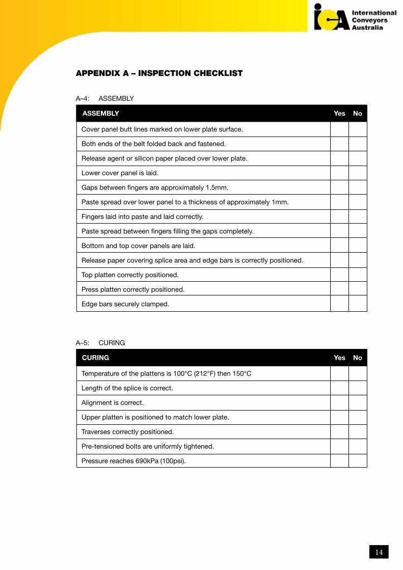
A–4: ASSEMBLY
A–5: CURING
Cover panel butt lines marked on lower plate surface.
Both ends of the belt folded back and fastened.
Release agent or silicon paper placed over lower plate.
Lower cover panel is laid.
Gaps between fingers are approximately 1.5mm.
Paste spread over lower panel to a thickness of approximately 1mm.
Fingers laid into paste and laid correctly.
Paste spread between fingers filling the gaps completely.
Bottom and top cover panels are laid.
Release paper covering splice area and edge bars is correctly positioned.
Top platten correctly positioned.
Press platten correctly positioned.
Edge bars securely clamped.
Temperature of the plattens is 100°C (212°F) then 150°C
Length of the splice is correct.
Alignment is correct.
Upper platten is positioned to match lower plate.
Traverses correctly positioned.
Pre-tensioned bolts are uniformly tightened.
Pressure reaches 690kPa (100psi).
ASSEMBLY
CURING
Yes
Yes
No
No
14

APPENDIX A – INSPECTION CHECKLIST
A–6: TESTING
Dimensions are with tolerance.
Splice / parent belt alignment are within tolerance.
Spew PVC / Nitrile have been removed.
There is no blister.
There is no lack of adhesion.
Shore hardness of covers is within tolerance.
Commissioning is satisfactory and Engineer’s approval has been obtained.
TESTING Yes No
15
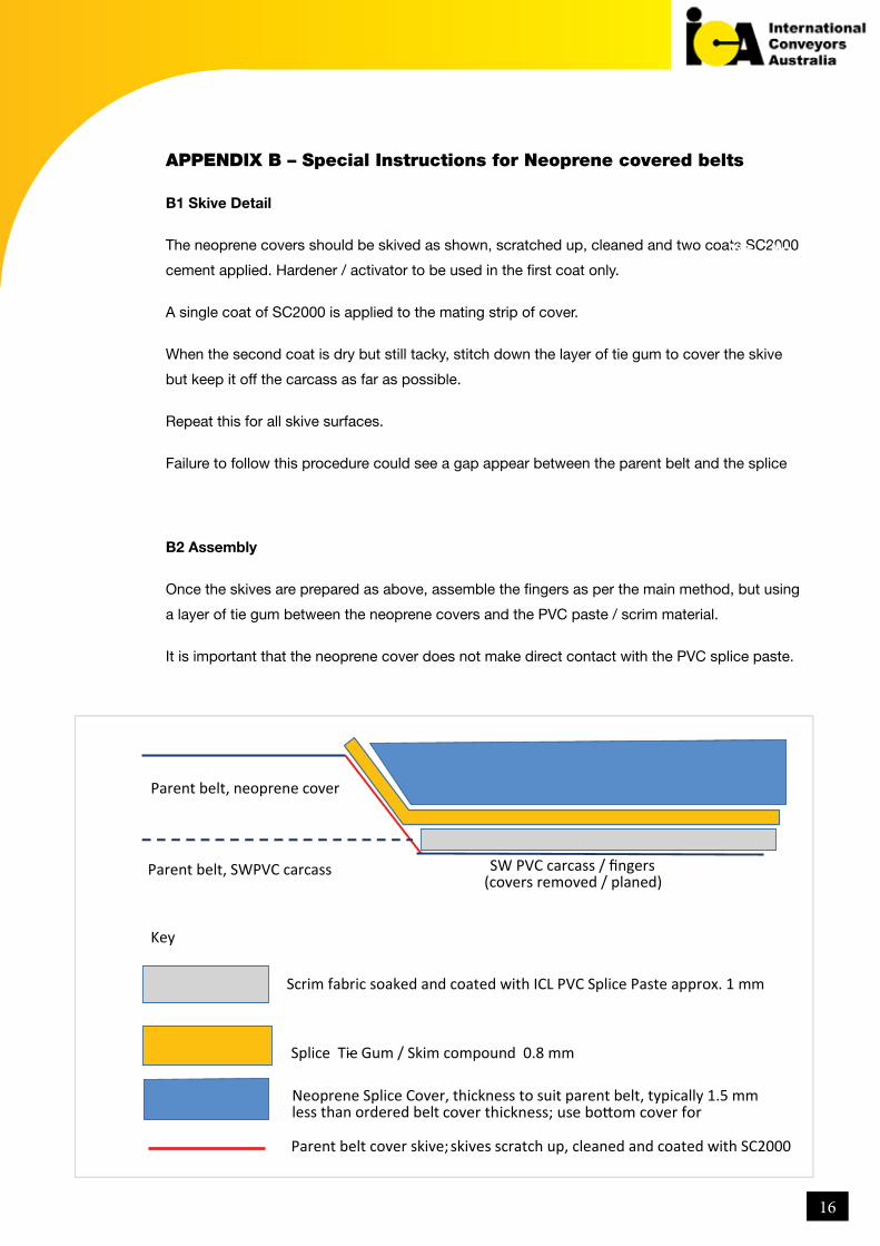
APPENDIX B – Special Instructions for Neoprene covered belts
B1 Skive Detail
The neoprene covers should be skived as shown, scratched up, cleaned and two coats SC2000
cement applied. Hardener / activator to be used in the first coat only.
A single coat of SC2000 is applied to the mating strip of cover.
When the second coat is dry but still tacky, stitch down the layer of tie gum to cover the skive
but keep it off the carcass as far as possible.
Repeat this for all skive surfaces.
Failure to follow this procedure could see a gap appear between the parent belt and the splice
B2 Assembly
Once the skives are prepared as above, assemble the fingers as per the main method, but using
a layer of tie gum between the neoprene covers and the PVC paste / scrim material.
It is important that the neoprene cover does not make direct contact with the PVC splice paste.
Yes No
Key
Parent belt, SWPVC carcass
Parent belt, neoprene cover
SW PVC carcass / fingers
(covers removed / planed)
Scrim fabric soaked and coated with ICL PVC Splice Paste approx. 1 mm
Splice Tie - Gum / Skim compound 0.8 mm
Neoprene Splice Cover, thickness to suit parent belt, typically 1.5 mm less than ordered belt cover thickness; use bottom cover for
skives
Parent belt cover skive;
scratch up, cleaned and coated with SC2000
16

INTERNATIONAL CONVEYORS BELT CURING SHEET RECORD.
P1 P2 P3 P4 P1 P2 P3 P4 psi or Kpa
splice Number cure temp
belt roll number belt thickness cure pressure
belt roll number belt thickness duration
SITE:
CONVEYOR:
DATE:
RECORDED BY:
Visual report on splice:
TOP PLATTERNSTime
BOTTOM PLATTERNS PRESSURE
17