VTU-NPTEL-NMEICT Project Progress Reportnptel.vtu.ac.in/VTU-NMEICT/MV/Module 5.pdf ·...
25
MODULE-V – VIBRATION ABSORBER VIBRATION ENGINEERING 2014 VTU-NPTEL-NMEICT Project Progress Report The Project on Development of Remaining Three Quadrants to NPTEL Phase-I under grant in aid NMEICT, MHRD, New Delhi DEPARTMENT OF MECHANICAL ENGINEERING, GHOUSIA COLLEGE OF ENGINEERING, RAMANARAM -562159 Subject Matter Expert Details SME Name : Dr.MOHAMED HANEEF PRINCIPAL, VTU SENATE MEMBER Course Name: Vibration engineering Type of the Course web Module V Dr.MOHAMED HANEEF ,PRINCIPAL,GHOUSIA COLLEGE OF ENGINEERING ,RAMANAGARAM VTU-NPTEL-NMEICT Project Page 1 of 25
Transcript of VTU-NPTEL-NMEICT Project Progress Reportnptel.vtu.ac.in/VTU-NMEICT/MV/Module 5.pdf ·...

MODULE-V – VIBRATION ABSORBER VIBRATION ENGINEERING 2014
VTU-NPTEL-NMEICT
Project Progress Report
The Project on Development of Remaining Three Quadrants to NPTEL Phase-I under grant in aid NMEICT, MHRD, New Delhi
DEPARTMENT OF MECHANICAL ENGINEERING,
GHOUSIA COLLEGE OF ENGINEERING,
RAMANARAM -562159
Subject Matter Expert Details
SME Name : Dr.MOHAMED HANEEF
PRINCIPAL, VTU SENATE MEMBER
Course Name:
Vibration engineering
Type of the Course
web
Module
V
Dr.MOHAMED HANEEF ,PRINCIPAL,GHOUSIA COLLEGE OF ENGINEERING ,RAMANAGARAM
VTU-NPTEL-N
MEICT Proj
ect
Page 1 of 25

MODULE-V – VIBRATION ABSORBER VIBRATION ENGINEERING 2014
CONTENTS
Sl. No. DISCRETION
1. Lecture Notes (Vibration absorber).
2. Quadrant -2
a. Animations.
b. Videos.
c. Illustrations.
3. Quadrant -3
a. Wikis.
b. Open Contents
4. Quadrant -4
a. Self Answered Question & Answer
b. Assignment
Dr.MOHAMED HANEEF ,PRINCIPAL,GHOUSIA COLLEGE OF ENGINEERING ,RAMANAGARAM
VTU-NPTEL-N
MEICT Proj
ect
Page 2 of 25

MODULE-V – VIBRATION ABSORBER VIBRATION ENGINEERING 2014
Module-V
VIBRATION ABSORBER LECTURE NOTES
1. Tuned absorber, Determination of mass ratio. Un-damped Dynamic Vibration Absorber Consider a two degree of freedom system with a forcing function 𝐹1 = 𝐹𝑜 𝑠𝑖𝑛𝜔𝑡 as shown in figure- 1(a). Consider original system of mass m1 which is under excitation. In this system suppose the
excitation frequency 𝜔is equal to the resonant frequency 𝜔𝑛 = �𝑘1𝑚1
the amplitude becomes very
large. If we coupled a spring mass system to the original system as shown in the fig 1(a), this spring mass system acts as an absorber and reduces the amplitude of vibration of mass m1 to
zero if its natural frequency is equal to the excitation frequency 𝜔 = �𝑘2𝑚2
Hence we have ω of original system= ω of modified system
𝑘1𝑚1
=𝑘2𝑚2
This relation is called as tuned absorber, which satisfied the absorber condition.
Figure- 1(a)
Figure 1(b)
Figure- (1) Two degree of freedom system with forcing function𝑭𝟏on mass 1
Dr.MOHAMED HANEEF ,PRINCIPAL,GHOUSIA COLLEGE OF ENGINEERING ,RAMANAGARAM
VTU-NPTEL-N
MEICT Proj
ect
Page 3 of 25
MODULE-V – VIBRATION ABSORBER VIBRATION ENGINEERING 2014
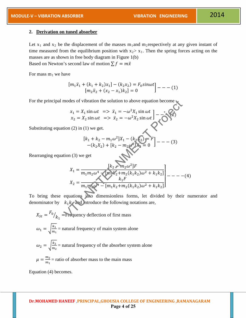
2. Derivation on tuned absorber
Let x1 and x2 be the displacement of the masses m1and m2respectively at any given instant of time measured from the equilibrium position with x2> x1. Then the spring forces acting on the masses are as shown in free body diagram in Figure 1(b) Based on Newton’s second law of motion ∑𝑓 = 𝑚�̈�
For mass m1 we have
[𝑚1�̈�1 + (𝑘1 + 𝑘2)𝑥1]− (𝑘2𝑥2) = 𝐹0𝑠𝑖𝑛𝜔𝑡[𝑚2�̈�2 + (𝑥2 − 𝑥1)𝑘2] = 0 � − − − (1)
For the principal modes of vibration the solution to above equation become
𝑥1 = 𝑋1 sin𝜔𝑡 => �̈�1 = −𝜔2𝑋1 sin𝜔𝑡 𝑥2 = 𝑋2 sin𝜔𝑡 => �̈�2 = −𝜔2𝑋2 sin𝜔𝑡
� − − − (2)
Substituting equation (2) in (1) we get.
[𝑘1 + 𝑘2 − 𝑚1𝜔2]𝑋1 − (𝑘2𝑋2) = 𝐹−(𝑘2𝑋2) + [𝑘2 −𝑚2𝜔2]𝑋2 = 0
� − − − (3)
Rearranging equation (3) we get
𝑋1 =[𝑘2 − 𝑚2𝜔2]𝐹
𝑚1𝑚2𝜔4 − [𝑚1𝑘2+𝑚2(𝑘1𝑘2)𝜔2 + 𝑘1𝑘2]
𝑋2 =𝑘1𝐹
𝑚1𝑚2𝜔4 − [𝑚1𝑘2+𝑚2(𝑘1𝑘2)𝜔2 + 𝑘1𝑘2]⎦⎥⎥⎥⎤− − − −(4)
To bring these equations into dimensionless forms, let divided by their numerator and denominator by 𝑘1𝑘2 and introduce the following notations are,
𝑋𝑆𝑡 = 𝐹0𝑘1� =Frequency deflection of first mass
𝜔1 = �𝑘1𝑚1
= natural frequency of main system alone
𝜔2 = �𝑘2𝑚2
= natural frequency of the absorber system alone
𝜇 = 𝑚2𝑚1
= ratio of absorber mass to the main mass
Equation (4) becomes.
Dr.MOHAMED HANEEF ,PRINCIPAL,GHOUSIA COLLEGE OF ENGINEERING ,RAMANAGARAM
VTU-NPTEL-N
MEICT Proj
ect
Page 4 of 25

MODULE-V – VIBRATION ABSORBER VIBRATION ENGINEERING 2014
𝑋1𝑋𝑠𝑡
=�1 − 𝜔2
𝜔22�
𝜔4
𝜔12𝜔2
2 − �(1 + 𝜇) 𝜔2
𝜔12 + 𝜔2
𝜔22� + 1
𝑋2𝑋𝑠𝑡
=�1 − 𝜔2
𝜔22�
𝜔4
𝜔12𝜔2
2 − �(1 + 𝜇) 𝜔2
𝜔12 + 𝜔2
𝜔22� + 1⎦
⎥⎥⎥⎥⎥⎥⎥⎤
− − − −(5)
Equation (5) clearly shows that 𝑋1 = 0 when 𝜔 = 𝜔1; that is when the excitation frequency of the absorber, the main system amplitude becomes zero even it is excited by harmonic force. This is the principle of an un-damped dynamic vibration absorber, since, if a main system has undesirable vibrations at the operating frequency, a secondary spring mass system (absorber system) having its natural frequency equal to the operating frequency can be coupled to the main system to reduce its amplitude to zero.
Substituting 𝜔 = 𝜔1 in equation (5) 𝑋2 amplitude become
𝑋2 = −𝑋𝑠𝑡
(𝜇) 𝜔2
𝜔12
= −𝑋𝑠𝑡
�𝑚2𝑚1
���𝑘2𝑚2
�2
��𝑘1𝑚1�2
=𝑋𝑠𝑡
�𝑚2𝑚1
� �𝑘2𝑚2� �𝑚1
𝑘1�
𝑖. 𝑒. 𝑋2 = −𝐹0 𝑘2�
𝐹0 = −𝑋2𝑘2� − − − −(6)
Above equation (6) indicates that, the main mass vibrations have been reduced to zero and the vibrations have been taken up by the absorber system. Hence the name called as vibration absorber.
The vibration absorber to main system is not much effective unless the main system is operating at least nearest to it, for this condition 𝜔1 = 𝜔. But for the absorber to be effective, we have𝜔2 = 𝜔. Therefore for the effectiveness of the absorber at the operating frequency corresponding to the natural frequency of the main system alone, we have
𝜔2 = 𝜔1𝑜𝑟 𝑘2𝑚2
=𝑘1𝑚1
−−−−(7)
When the above condition is fulfilled, the absorber is known as tuned absorber.
For tuned absorber equation (5) becomes
Dr.MOHAMED HANEEF ,PRINCIPAL,GHOUSIA COLLEGE OF ENGINEERING ,RAMANAGARAM
VTU-NPTEL-N
MEICT Proj
ect
Page 5 of 25

MODULE-V – VIBRATION ABSORBER VIBRATION ENGINEERING 2014
𝑋1𝑋𝑠𝑡
=�1 − 𝜔2
𝜔22�
𝜔4
𝜔24 − �(2 + 𝜇) 𝜔
2
𝜔22� + 1
𝑋2𝑋𝑠𝑡
=1
𝜔4
𝜔24 − �(2 + 𝜇) 𝜔
2
𝜔22� + 1⎦
⎥⎥⎥⎥⎥⎤
− − − −(8)
Equation (7) is holds good at 𝜔 = 𝜔2, at which point 𝑋2 = 0
3. Determination of mass ratio.
μ is the mass ratio = m2/m1. where ω1 = �k1m1
and ω2 = �k2m2
, However, the natural or resonant
frequencies of the 2-degree of freedom system formed after attaching the auxiliary system are
given by different expressions in terms of m1, m2, k1, and k2.
Plot of the dimensionless responses of each of the two masses is shown above when a harmonic
force acts on m1 when excitation frequency is close to resonant frequency of main system,
ω ≠ω1 , but much away from resonant frequency of auxiliary system, ω ≠ω2, Mass ratio
between μ=m2/m1= 0.5 to 2.5.
In denominators of equations (8) are identical. At a value of ω when these denominators are zero, the two masses have infinite amplitudes of vibration. The expression for the denominators is a quadratic in ω2 and therefore there are two values of ω for which these expressions vanish.
From equation (8)
𝜔4
𝜔24 − �(2 + 𝜇)
𝜔2
𝜔22� + 1 = 0 −−− (9)
Solving for ωω2
we have
�𝜔𝜔2�2
= �1 +𝜇2�± �𝜇 +
𝜇2
4 −−− (10)
The relationship of equation (10) is plotted in figure below from this plot we see that greater the
mass ratio 𝜇, greater is the spread between the two resonant frequencies.
Dr.MOHAMED HANEEF ,PRINCIPAL,GHOUSIA COLLEGE OF ENGINEERING ,RAMANAGARAM
VTU-NPTEL-N
MEICT Proj
ect
Page 6 of 25

MODULE-V – VIBRATION ABSORBER VIBRATION ENGINEERING 2014
𝜇
Figure: effect of mass ratio on natural (resonant) frequency.
The dimensionless response curves for the main system and the absorber system given by the equation (10) are shown in figures below for a value of 𝜇 = 0.2. the dotted curves shown actually mean that the amplitude is negative or its phase difference with respect to the exiting force is 1800. These portions of the curves, however, are shown on positive side of the ordinate. It can be seen from hese curves that when 𝜔1
𝜔2< 1, the phase difference between them is 1800.
For the system alone without absorber we have only one resonant frequency at 𝜔1𝜔2
= 1. Imagine
for the main system alone, the exciting frequency is very close to its natural frequency. To overcome this resonant condition we attach a vibration absorber (𝜔1 = 𝜔2) to the main system, thereby reducing its vibration to zero. When the amplitudes are equal
𝜔2
𝜔1= �
11 + 𝜇
�
𝜔𝜔2
−−− →
𝑋1𝑋𝑠𝑡� ↑
𝜔2 = 𝜔1 𝜔𝜔2
Dr.MOHAMED HANEEF ,PRINCIPAL,GHOUSIA COLLEGE OF ENGINEERING ,RAMANAGARAM
VTU-NPTEL-N
MEICT Proj
ect
Page 7 of 25

MODULE-V – VIBRATION ABSORBER VIBRATION ENGINEERING 2014
Fig:(a)
𝜔𝜔2
−−− →
Fig: (b) Figure: frequency-response curves for (a) main system, (b) absorber.
𝜔2 = 𝜔1
𝜇 = 0.20
Dr.MOHAMED HANEEF ,PRINCIPAL,GHOUSIA COLLEGE OF ENGINEERING ,RAMANAGARAM
VTU-NPTEL-N
MEICT Proj
ect
Page 8 of 25

MODULE-V – VIBRATION ABSORBER VIBRATION ENGINEERING 2014
4. Tuned and damped absorber, Unturned Dry friction damper: This type of damper is very useful in reducing the amplitude of torsional vibrations near resonance conditions figure shown below a dry friction type of damper known as Lanchester damper.
Figure: Lanchester damper.
It consists of two flywheels which can rotate freely on the shaft bearings. There is a hub in between rigidly fixed to the shaft. The hub carries friction lining on its faces against which the flywheels can be pressed by screwing down the coil springs. If the engine I.e. hub executes torsional vibrations, the motion of the flywheels depend upon the amount of friction between them and the hub. If the friction torque is zero i.e. pressure between the frictional plates and flywheel become zero, the relative velocity is maximum. Since friction torque is zero, there is no energy dissipation. On the other hand, if friction torque is very large i.e. pressure between the friction plates and flywheels is excessive, the flywheels become rigid with the shaft and have same oscillation at that shaft. There is thus, no relative slip and hence no energy dissipation. However, between these two extremes, there is both friction torque and slip, so that energy is dissipated. This reduces the amplitude of torsional oscillations. Greater is the amount of energy dissipation, greater will be reduction in amplitude of vibration. The energy dissipation V/a frictional torque plot is shown in figure below.
Dr.MOHAMED HANEEF ,PRINCIPAL,GHOUSIA COLLEGE OF ENGINEERING ,RAMANAGARAM
VTU-NPTEL-N
MEICT Proj
ect
Page 9 of 25

MODULE-V – VIBRATION ABSORBER VIBRATION ENGINEERING 2014
Figure: energy dissipation V/a frictional torque.
5. Unturned viscous dampers: This type of damper is useful for damping out torsional oscillations. Shown in Fig: (a) a unturned viscous damper commonly known as Haudaillc Damper. It is similar in principle to the Lanchester Damper Except that instead of dry friction damping is employed in this case. It consists of a flywheel which can rotate freely about the hub. The hub is splined inside so that it can be attached easily to the shaft end. The flywheel is enclosed in housing, welded to the hub. The clearance between the housing and flywheel is filled with silicone fluid. Silicone oil is used because of its high viscosity index i.e., its viscosity changes relatively little with temperature. The flywheel rotates at the shaft speed owing to viscous drag of the fluid.
Figure: Unturned viscous dampers
When the damping is zero in the damper, it is ineffective and the system reduces to one degree of freedom system. If the damping is infinite, the damper mass becomes integral with the main
Dr.MOHAMED HANEEF ,PRINCIPAL,GHOUSIA COLLEGE OF ENGINEERING ,RAMANAGARAM
VTU-NPTEL-N
MEICT Proj
ect
Page 10 of 25

MODULE-V – VIBRATION ABSORBER VIBRATION ENGINEERING 2014
mass. It still remains a single degree of feedom. The frquency response curve is of same nature except that the peak shifts to the right as shown by curve (b)
Figure: response curve for untuned viscous damper for
(a) zero damping, (b) infinte damping, (c) optimal damping.
The point of intersection of the above two curve (for ζ = 0 and ζ = ∞) is the point through which the response curve of different damping values pass. It is impossible to reduce the peak amplitude below this point. So, a system having optimal damping has its response curve with P as the highest point. We start by assuming optimal damping, calculate the system. Find the dangerous frequency and then specify the damping, c for the damping the flywheel and housing, affect the value of C.
Dr.MOHAMED HANEEF ,PRINCIPAL,GHOUSIA COLLEGE OF ENGINEERING ,RAMANAGARAM
VTU-NPTEL-N
MEICT Proj
ect
Page 11 of 25

MODULE-V – VIBRATION ABSORBER VIBRATION ENGINEERING 2014
QUADRANT-2 Animations (Animation links related to Vibration Absorber)
• http://en.wikipedia.org/wiki/Tuned_mass_damper • http://www.acs.psu.edu/drussell/Demos/absorber/DynamicAbsorber.html • http://en.wikipedia.org/wiki/Dynamic_Vibration_Absorber
Videos (video links related ,to Vibration Absorber)
• http://www.youtube.com/watch?v=JPJIg9soDYc • http://www.learnerstv.com/video/Free-video-Lecture-2292-engineering.htm • http://www.cosmolearning.com/video-lectures/tuned-vibration-absorber/ • http://freevideolectures.com/Course/2364/Dynamics-of-Machines/33 • http://www.onlinevideolecture.com/mechanical-engineering/nptel-iit-
guwahati/mechanical-vibrations/index.php?course_id=541&lecture_no=17 • http://www.onlinevideolecture.com/mechanical-engineering/nptel-iit-
kanpur/dynamics-of-machines/index.php?course_id=560&lecture_no=21 • http://www.learningace.com/doc/407947/07bc1093f1c22840a3057fd1474c563a/modu
le-12-lecture-2-tuned-vibration-absorber ILLUSTRATION
Dr.MOHAMED HANEEF ,PRINCIPAL,GHOUSIA COLLEGE OF ENGINEERING ,RAMANAGARAM
VTU-NPTEL-N
MEICT Proj
ect
Page 12 of 25

MODULE-V – VIBRATION ABSORBER VIBRATION ENGINEERING 2014
1. A section of pipe pertaining to a certain machine vibrates with large amplitude at a
compressor speed of 220 r.p.m. for analyzing this system a spring-mass system was suspended form the pipe to act an absorber. A 1kg absorber mass tuned to 220 c.p.m. what must be the mass and the spring stiffness of the absorber if the resonant frequencies are to lie outside the range of 150 to 310 c.p.m.?
Solution:
𝜔1 = 220 ×2𝜋60
= 23.0 𝑟𝑎𝑑/𝑠𝑒𝑐 𝜔2 = 23.0 𝑟𝑎𝑑/𝑠𝑒𝑐
𝑀1 = 1𝑘𝑔
𝑘2 = 𝑀1𝜔22 = 1 × 232 = 529 𝑁/𝑚
𝜔𝑛1 = 188 ×2𝜋60
= 19.7 𝑟𝑎𝑑/𝑠𝑒𝑐
𝜔𝑛2 = 258 ×2𝜋60
= 27.0 𝑟𝑎𝑑/𝑠𝑒𝑐
For 𝜔2 = 𝜔1, we apply equation to find µ by taking first 𝜔 = 𝜔𝑛1, and then 𝜔 = 𝜔𝑛2,
When 𝜔 = 𝜔𝑛1 = 19.7, 𝜇 = 0.100
𝜔 = 𝜔𝑛2 = 27.0, 𝜇 = 0.104
The average value of 𝜇 therefore is
𝜇 = 0.102 =𝑀2
𝑀1
𝑀1 =𝑀2
0.102=
10.102
= 9.8 𝑘𝑔
Also
𝑘1 =𝑘2
0.102=
5290.102
= 5194 𝑁/𝑚
After finding the weight and the stiffness of the main system it is required first to find 𝜇 so that new resonant frequencies will not be in specified range.
𝜔𝑛1
𝜔2=
150220
= 0.681
Dr.MOHAMED HANEEF ,PRINCIPAL,GHOUSIA COLLEGE OF ENGINEERING ,RAMANAGARAM
VTU-NPTEL-N
MEICT Proj
ect
Page 13 of 25

MODULE-V – VIBRATION ABSORBER VIBRATION ENGINEERING 2014
𝜔𝑛2
𝜔2=
310220
= 1.41
W.K.T two corresponding values of 𝜇 are 0.62 and 0.493. choosing the higher the value, we get
𝜇 = 0.62
Therefore, 𝑀1 = 0.62 × 9.8 = 6.06 𝑘𝑔
𝑘1 = 0.62 × 5194 = 3224 𝑁/𝑚
2. Derive an expression for tuned Absorber.
Solution:
Let x1 and x2 be the displacement of the masses m1and m2respectively at any given instant of time measured from the equilibrium position with x2> x1. Then the spring forces acting on the masses are as shown in free body diagram in Figure 1(b) Based on Newton’s second law of motion ∑𝑓 = 𝑚�̈�
For mass m1 we have
[𝑚1�̈�1 + (𝑘1 + 𝑘2)𝑥1]− (𝑘2𝑥2) = 𝐹0𝑠𝑖𝑛𝜔𝑡[𝑚2�̈�2 + (𝑥2 − 𝑥1)𝑘2] = 0 � − − − (1)
For the principal modes of vibration the solution to above equation become
𝑥1 = 𝑋1 sin𝜔𝑡 => �̈�1 = −𝜔2𝑋1 sin𝜔𝑡 𝑥2 = 𝑋2 sin𝜔𝑡 => �̈�2 = −𝜔2𝑋2 sin𝜔𝑡
� − − − (2)
Substituting equation (2) in (1) we get.
[𝑘1 + 𝑘2 − 𝑚1𝜔2]𝑋1 − (𝑘2𝑋2) = 𝐹−(𝑘2𝑋2) + [𝑘2 −𝑚2𝜔2]𝑋2 = 0
� − − − (3)
Rearranging equation (3) we get
𝑋1 =[𝑘2 − 𝑚2𝜔2]𝐹
𝑚1𝑚2𝜔4 − [𝑚1𝑘2+𝑚2(𝑘1𝑘2)𝜔2 + 𝑘1𝑘2]
𝑋2 =𝑘1𝐹
𝑚1𝑚2𝜔4 − [𝑚1𝑘2+𝑚2(𝑘1𝑘2)𝜔2 + 𝑘1𝑘2]⎦⎥⎥⎥⎤− − − −(4)
To bring these equations into dimensionless forms, let divided by their numerator and denominator by 𝑘1𝑘2 and introduce the following notations are,
𝑋𝑆𝑡 = 𝐹0𝑘1� =Frequency deflection of first mass
Dr.MOHAMED HANEEF ,PRINCIPAL,GHOUSIA COLLEGE OF ENGINEERING ,RAMANAGARAM
VTU-NPTEL-N
MEICT Proj
ect
Page 14 of 25

MODULE-V – VIBRATION ABSORBER VIBRATION ENGINEERING 2014
𝜔1 = �𝑘1𝑚1
= natural frequency of main system alone
𝜔2 = �𝑘2𝑚2
= natural frequency of the absorber system alone
𝜇 = 𝑚2𝑚1
= ratio of absorber mass to the main mass
Equation (4) becomes.
𝑋1𝑋𝑠𝑡
=�1 − 𝜔2
𝜔22�
𝜔4
𝜔12𝜔2
2 − �(1 + 𝜇) 𝜔2
𝜔12 + 𝜔2
𝜔22� + 1
𝑋2𝑋𝑠𝑡
=�1 − 𝜔2
𝜔22�
𝜔4
𝜔12𝜔2
2 − �(1 + 𝜇) 𝜔2
𝜔12 + 𝜔2
𝜔22� + 1⎦
⎥⎥⎥⎥⎥⎥⎥⎤
− − − −(5)
Equation (5) clearly shows that 𝑋1 = 0 when 𝜔 = 𝜔1; that is when the excitation frequency of the absorber, the main system amplitude becomes zero even it is excited by harmonic force. This is the principle of an un-damped dynamic vibration absorber, since, if a main system has undesirable vibrations at the operating frequency, a secondary spring mass system (absorber system) having its natural frequency equal to the operating frequency can be coupled to the main system to reduce its amplitude to zero.
Substituting 𝜔 = 𝜔1 in equation (5) 𝑋2 amplitude become
𝑋2 = −𝑋𝑠𝑡
(𝜇) 𝜔2
𝜔12
= −𝑋𝑠𝑡
�𝑚2𝑚1
���𝑘2𝑚2
�2
��𝑘1𝑚1�2
=𝑋𝑠𝑡
�𝑚2𝑚1
� �𝑘2𝑚2� �𝑚1
𝑘1�
𝑖. 𝑒. 𝑋2 = −𝐹0 𝑘2�
𝐹0 = −𝑋2𝑘2� − − − −(6)
Above equation (6) indicates that, the main mass vibrations have been reduced to zero and the vibrations have been taken up by the absorber system. Hence the name called as vibration absorber.
The vibration absorber to main system is not much effective unless the main system is operating at least nearest to it, for this condition 𝜔1 = 𝜔. But for the absorber to be effective, we
Dr.MOHAMED HANEEF ,PRINCIPAL,GHOUSIA COLLEGE OF ENGINEERING ,RAMANAGARAM
VTU-NPTEL-N
MEICT Proj
ect
Page 15 of 25

MODULE-V – VIBRATION ABSORBER VIBRATION ENGINEERING 2014
have𝜔2 = 𝜔. Therefore for the effectiveness of the absorber at the operating frequency corresponding to the natural frequency of the main system alone, we have
𝜔2 = 𝜔1𝑜𝑟 𝑘2𝑚2
=𝑘1𝑚1
−−−−(7)
When the above condition is fulfilled, the absorber is known as tuned absorber.
For tuned absorber equation (5) becomes
𝑋1𝑋𝑠𝑡
=�1 − 𝜔2
𝜔22�
𝜔4
𝜔24 − �(2 + 𝜇) 𝜔
2
𝜔22� + 1
𝑋2𝑋𝑠𝑡
=1
𝜔4
𝜔24 − �(2 + 𝜇) 𝜔
2
𝜔22� + 1⎦
⎥⎥⎥⎥⎥⎤
− − − −(8)
Equation (7) is holds good at 𝜔 = 𝜔2, at which point 𝑋2 = 0
3. Explain with neat sketche Lanchester Damper .
Solution :
This type of damper is very useful in reducing the amplitude of torsional vibrations near resonance conditions figure shown below a dry friction type of damper known as Lanchester damper.
Figure: Lanchester damper.
Dr.MOHAMED HANEEF ,PRINCIPAL,GHOUSIA COLLEGE OF ENGINEERING ,RAMANAGARAM
VTU-NPTEL-N
MEICT Proj
ect
Page 16 of 25

MODULE-V – VIBRATION ABSORBER VIBRATION ENGINEERING 2014
It consists of two flywheels which can rotate freely on the shaft bearings. There is a hub in between rigidly fixed to the shaft. The hub carries friction lining on its faces against which the flywheels can be pressed by screwing down the coil springs.
If the engine I.e. hub executes torsional vibrations, the motion of the flywheels depend upon the amount of friction between them and the hub. If the friction torque is zero i.e. pressure between the frictional plates and flywheel become zero, the relative velocity is maximum. Since friction torque is zero, there is no energy dissipation. On the other hand, if friction torque is very large i.e. pressure between the friction plates and flywheels is excessive, the flywheels become rigid with the shaft and have same oscillation at that shaft. There is thus, no relative slip and hence no energy dissipation. However, between these two extremes, there is both friction torque and slip, so that energy is dissipated. This reduces the amplitude of torsional oscillations.
Greater is the amount of energy dissipation, greater will be reduction in amplitude of vibration.
The energy dissipation V/a frictional torque plot is shown in figure below.
Figure: energy dissipation V/a frictional torque.
4. Explain with a neat sketch Viscous Damper.
Solution)
This type of damper is useful for damping out torsional oscillations. Shown in Fig: (a) a unturned viscous damper commonly known as Haudaillc Damper.
It is similar in principle to the Lanchester Damper Except that instead of dry friction damping is employed in this case.
Dr.MOHAMED HANEEF ,PRINCIPAL,GHOUSIA COLLEGE OF ENGINEERING ,RAMANAGARAM
VTU-NPTEL-N
MEICT Proj
ect
Page 17 of 25

MODULE-V – VIBRATION ABSORBER VIBRATION ENGINEERING 2014
It consists of a flywheel which can rotate freely about the hub. The hub is splined inside so that it can be attached easily to the shaft end. The flywheel is enclosed in housing, welded to the hub. The clearance between the housing and flywheel is filled with silicone fluid. Silicone oil is used because of its high viscosity index i.e., its viscosity changes relatively little with temperature. The flywheel rotates at the shaft speed owing to viscous drag of the fluid.
Figure(a): Unturned viscous dampers
When the damping is zero in the damper, it is ineffective and the system reduces to one degree of freedom system. If the damping is infinite, the damper mass becomes integral with the main mass. It still remains a single degree of feedom. The frquency response curve is of same nature except that the peak shifts to the right as shown by curve (b)
Figure: response curve for untuned viscous damper for
(a) zero damping, (b) infinte damping, (c) optimal damping.
Dr.MOHAMED HANEEF ,PRINCIPAL,GHOUSIA COLLEGE OF ENGINEERING ,RAMANAGARAM
VTU-NPTEL-N
MEICT Proj
ect
Page 18 of 25
MODULE-V – VIBRATION ABSORBER VIBRATION ENGINEERING 2014
The point of intersection of the above two curve (for ζ = 0 and ζ = ∞) is the point through which the response curve of different damping values pass. It is impossible to reduce the peak amplitude below this point. So, a system having optimal damping has its response curve with P as the highest point. We start by assuming optimal damping, calculate the system. Find the dangerous frequency and then specify the damping, c for the damping the flywheel and housing, affect the value of C.
QUADRANT-3
Wikis: (This includes wikis related to Vibration Absorber)
• http://en.wikipedia.org/wiki/Dynamic_Vibration_Absorber • http://en.wikipedia.org/wiki/Tuned_mass_damper • http://en.wikipedia.org/wiki/Stockbridge_damper • http://en.wiktionary.org/wiki/viscous_damper • http://opensees.berkeley.edu/wiki/index.php/ViscousDamper_Material
Open Contents: (This includes wikis related to Continuous System : Closed form solution))
• Mechanical Vibrations, S. S. Rao, Pearson Education Inc, 4th edition, 2003. • Mechanical Vibrations, V. P. Singh, Dhanpat Rai & Company, 3rd edition, 2006. • Mechanical Vibrations, G. K.Grover, Nem Chand and Bros, 6th edition, 1996 • Theory of vibration with applications ,W.T.Thomson,M.D.Dahleh and C
Padmanabhan,Pearson Education inc,5th Edition ,2008 • Theory and practice of Mechanical Vibration : J.S.Rao&K,Gupta,New Age International
Publications ,New Delhi,2001
Dr.MOHAMED HANEEF ,PRINCIPAL,GHOUSIA COLLEGE OF ENGINEERING ,RAMANAGARAM
VTU-NPTEL-N
MEICT Proj
ect
Page 19 of 25

MODULE-V – VIBRATION ABSORBER VIBRATION ENGINEERING 2014
QUADRANT-4
Self Answered Question & Answer
1. Derive an expression for tuned Absorber.
Solution:
Let x1 and x2 be the displacement of the masses m1and m2respectively at any given instant of time measured from the equilibrium position with x2> x1. Then the spring forces acting on the masses are as shown in free body diagram in Figure 1(b) Based on Newton’s second law of motion ∑𝑓 = 𝑚�̈�
For mass m1 we have
[𝑚1�̈�1 + (𝑘1 + 𝑘2)𝑥1]− (𝑘2𝑥2) = 𝐹0𝑠𝑖𝑛𝜔𝑡[𝑚2�̈�2 + (𝑥2 − 𝑥1)𝑘2] = 0 � − − − (1)
For the principal modes of vibration the solution to above equation become
𝑥1 = 𝑋1 sin𝜔𝑡 => �̈�1 = −𝜔2𝑋1 sin𝜔𝑡 𝑥2 = 𝑋2 sin𝜔𝑡 => �̈�2 = −𝜔2𝑋2 sin𝜔𝑡
� − − − (2)
Substituting equation (2) in (1) we get.
[𝑘1 + 𝑘2 − 𝑚1𝜔2]𝑋1 − (𝑘2𝑋2) = 𝐹−(𝑘2𝑋2) + [𝑘2 −𝑚2𝜔2]𝑋2 = 0
� − − − (3)
Rearranging equation (3) we get
𝑋1 =[𝑘2 − 𝑚2𝜔2]𝐹
𝑚1𝑚2𝜔4 − [𝑚1𝑘2+𝑚2(𝑘1𝑘2)𝜔2 + 𝑘1𝑘2]
𝑋2 =𝑘1𝐹
𝑚1𝑚2𝜔4 − [𝑚1𝑘2+𝑚2(𝑘1𝑘2)𝜔2 + 𝑘1𝑘2]⎦⎥⎥⎥⎤− − − −(4)
To bring these equations into dimensionless forms, let divided by their numerator and denominator by 𝑘1𝑘2 and introduce the following notations are,
𝑋𝑆𝑡 = 𝐹0𝑘1� =Frequency deflection of first mass
𝜔1 = �𝑘1𝑚1
= natural frequency of main system alone
𝜔2 = �𝑘2𝑚2
= natural frequency of the absorber system alone
Dr.MOHAMED HANEEF ,PRINCIPAL,GHOUSIA COLLEGE OF ENGINEERING ,RAMANAGARAM
VTU-NPTEL-N
MEICT Proj
ect
Page 20 of 25

MODULE-V – VIBRATION ABSORBER VIBRATION ENGINEERING 2014
𝜇 = 𝑚2𝑚1
= ratio of absorber mass to the main mass
Equation (4) becomes.
𝑋1𝑋𝑠𝑡
=�1 − 𝜔2
𝜔22�
𝜔4
𝜔12𝜔2
2 − �(1 + 𝜇) 𝜔2
𝜔12 + 𝜔2
𝜔22� + 1
𝑋2𝑋𝑠𝑡
=�1 − 𝜔2
𝜔22�
𝜔4
𝜔12𝜔2
2 − �(1 + 𝜇) 𝜔2
𝜔12 + 𝜔2
𝜔22� + 1⎦
⎥⎥⎥⎥⎥⎥⎥⎤
− − − −(5)
Equation (5) clearly shows that 𝑋1 = 0 when 𝜔 = 𝜔1; that is when the excitation frequency of the absorber, the main system amplitude becomes zero even it is excited by harmonic force. This is the principle of an un-damped dynamic vibration absorber, since, if a main system has undesirable vibrations at the operating frequency, a secondary spring mass system (absorber system) having its natural frequency equal to the operating frequency can be coupled to the main system to reduce its amplitude to zero.
Substituting 𝜔 = 𝜔1 in equation (5) 𝑋2 amplitude become
𝑋2 = −𝑋𝑠𝑡
(𝜇) 𝜔2
𝜔12
= −𝑋𝑠𝑡
�𝑚2𝑚1
���𝑘2𝑚2
�2
��𝑘1𝑚1�2
=𝑋𝑠𝑡
�𝑚2𝑚1
� �𝑘2𝑚2� �𝑚1
𝑘1�
𝑖. 𝑒. 𝑋2 = −𝐹0 𝑘2�
𝐹0 = −𝑋2𝑘2� − − − −(6)
Above equation (6) indicates that, the main mass vibrations have been reduced to zero and the vibrations have been taken up by the absorber system. Hence the name called as vibration absorber.
The vibration absorber to main system is not much effective unless the main system is operating at least nearest to it, for this condition 𝜔1 = 𝜔. But for the absorber to be effective, we have𝜔2 = 𝜔. Therefore for the effectiveness of the absorber at the operating frequency corresponding to the natural frequency of the main system alone, we have
𝜔2 = 𝜔1𝑜𝑟 𝑘2𝑚2
=𝑘1𝑚1
−−−−(7)
Dr.MOHAMED HANEEF ,PRINCIPAL,GHOUSIA COLLEGE OF ENGINEERING ,RAMANAGARAM
VTU-NPTEL-N
MEICT Proj
ect
Page 21 of 25

MODULE-V – VIBRATION ABSORBER VIBRATION ENGINEERING 2014
When the above condition is fulfilled, the absorber is known as tuned absorber.
For tuned absorber equation (5) becomes
𝑋1𝑋𝑠𝑡
=�1 − 𝜔2
𝜔22�
𝜔4
𝜔24 − �(2 + 𝜇) 𝜔
2
𝜔22� + 1
𝑋2𝑋𝑠𝑡
=1
𝜔4
𝜔24 − �(2 + 𝜇) 𝜔
2
𝜔22� + 1⎦
⎥⎥⎥⎥⎥⎤
− − − −(8)
Equation (7) is holds good at 𝜔 = 𝜔2, at which point 𝑋2 = 0
2. Explain with neat sketch Lanchester Damper .
Solution :
This type of damper is very useful in reducing the amplitude of torsional vibrations near resonance conditions figure shown below a dry friction type of damper known as Lanchester damper.
Figure: Lanchester damper.
Dr.MOHAMED HANEEF ,PRINCIPAL,GHOUSIA COLLEGE OF ENGINEERING ,RAMANAGARAM
VTU-NPTEL-N
MEICT Proj
ect
Page 22 of 25

MODULE-V – VIBRATION ABSORBER VIBRATION ENGINEERING 2014
It consists of two flywheels which can rotate freely on the shaft bearings. There is a hub in between rigidly fixed to the shaft. The hub carries friction lining on its faces against which the flywheels can be pressed by screwing down the coil springs.
If the engine I.e. hub executes torsional vibrations, the motion of the flywheels depend upon the amount of friction between them and the hub. If the friction torque is zero i.e. pressure between the frictional plates and flywheel become zero, the relative velocity is maximum. Since friction torque is zero, there is no energy dissipation. On the other hand, if friction torque is very large i.e. pressure between the friction plates and flywheels is excessive, the flywheels become rigid with the shaft and have same oscillation at that shaft. There is thus, no relative slip and hence no energy dissipation. However, between these two extremes, there is both friction torque and slip, so that energy is dissipated. This reduces the amplitude of torsional oscillations.
Greater is the amount of energy dissipation, greater will be reduction in amplitude of vibration.
The energy dissipation V/a frictional torque plot is shown in figure below.
Figure: energy dissipation V/a frictional torque.
3. Explain with a neat sketch Viscous Damper.
Solution)
This type of damper is useful for damping out torsional oscillations. Shown in Fig: (a) a unturned viscous damper commonly known as Haudaillc Damper.
It is similar in principle to the Lanchester Damper Except that instead of dry friction damping is employed in this case.
Dr.MOHAMED HANEEF ,PRINCIPAL,GHOUSIA COLLEGE OF ENGINEERING ,RAMANAGARAM
VTU-NPTEL-N
MEICT Proj
ect
Page 23 of 25

MODULE-V – VIBRATION ABSORBER VIBRATION ENGINEERING 2014
It consists of a flywheel which can rotate freely about the hub. The hub is splined inside so that it can be attached easily to the shaft end. The flywheel is enclosed in housing, welded to the hub. The clearance between the housing and flywheel is filled with silicone fluid. Silicone oil is used because of its high viscosity index i.e., its viscosity changes relatively little with temperature. The flywheel rotates at the shaft speed owing to viscous drag of the fluid.
Figure(a): Unturned viscous dampers
When the damping is zero in the damper, it is ineffective and the system reduces to one degree of freedom system. If the damping is infinite, the damper mass becomes integral with the main mass. It still remains a single degree of feedom. The frquency response curve is of same nature except that the peak shifts to the right as shown by curve (b)
Figure: response curve for untuned viscous damper for
(b) zero damping, (b) infinte damping, (c) optimal damping.
Dr.MOHAMED HANEEF ,PRINCIPAL,GHOUSIA COLLEGE OF ENGINEERING ,RAMANAGARAM
VTU-NPTEL-N
MEICT Proj
ect
Page 24 of 25

MODULE-V – VIBRATION ABSORBER VIBRATION ENGINEERING 2014
The point of intersection of the above two curve (for ζ = 0 and ζ = ∞) is the point through which the response curve of different damping values pass. It is impossible to reduce the peak amplitude below this point. So, a system having optimal damping has its response curve with P as the highest point. We start by assuming optimal damping, calculate the system. Find the dangerous frequency and then specify the damping, c for the damping the flywheel and housing, affect the value of C.
Assignment: 1. Derive an expression for tuned Absorber.
2. Explain with a neat sketch Viscous Damper. 3. Explain with neat sketche Lanchester Damper .
4. Derive an expression for tuned Absorber.
5. A section of pipe pertaining to a certain machine vibrates with large amplitude at a compressor speed of 220 r.p.m. for analyzing this system a spring-mass system was suspended form the pipe to act an absorber. A 1kg absorber mass tuned to 220 c.p.m. what must be the mass and the spring stiffness of the absorber if the resonant frequencies are to lie outside the range of 150 to 310 c.p.m.?
Dr.MOHAMED HANEEF ,PRINCIPAL,GHOUSIA COLLEGE OF ENGINEERING ,RAMANAGARAM
VTU-NPTEL-N
MEICT Proj
ect
Page 25 of 25