VTO Series - Dahua Technology USA Inc...VTO Series User’s Manual Dahua Technology Co., Ltd I...
42
VTO Series User’s Manual Dahua Technology Co., Ltd
Transcript of VTO Series - Dahua Technology USA Inc...VTO Series User’s Manual Dahua Technology Co., Ltd I...

VTO Series
User’s Manual
Dahua Technology Co., Ltd
I
Foreword General
This manual offers reference material and general information about the basic operation, maintenance, and troubleshooting for a Dahua security device. Read, follow, and retain the following safety instructions. Heed all warning on the unit and in the operating instructions before operating the unit. Keep this guide for future reference.
Safety Instructions The following categorized signal words with defined meaning might appear in the Guide.
Signal Words Meaning
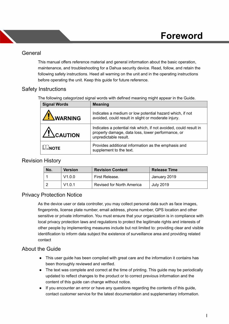
WARNING Indicates a medium or low potential hazard which, if not avoided, could result in slight or moderate injury.
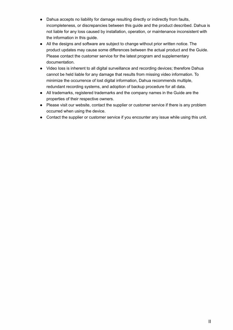
CAUTION
Indicates a potential risk which, if not avoided, could result in property damage, data loss, lower performance, or unpredictable result.
NOTE Provides additional information as the emphasis and supplement to the text.
Revision History No. Version Revision Content Release Time 1 V1.0.0 First Release. January 2019
2 V1.0.1 Revised for North America July 2019
Privacy Protection Notice As the device user or data controller, you may collect personal data such as face images, fingerprints, license plate number, email address, phone number, GPS location and other sensitive or private information. You must ensure that your organization is in compliance with local privacy protection laws and regulations to protect the legitimate rights and interests of other people by implementing measures include but not limited to: providing clear and visible identification to inform data subject the existence of surveillance area and providing related contact
About the Guide This user guide has been compiled with great care and the information it contains has
been thoroughly reviewed and verified. The text was complete and correct at the time of printing. This guide may be periodically
updated to reflect changes to the product or to correct previous information and the content of this guide can change without notice.
If you encounter an error or have any questions regarding the contents of this guide, contact customer service for the latest documentation and supplementary information.
II
Dahua accepts no liability for damage resulting directly or indirectly from faults, incompleteness, or discrepancies between this guide and the product described. Dahua is not liable for any loss caused by installation, operation, or maintenance inconsistent with the information in this guide.
All the designs and software are subject to change without prior written notice. The product updates may cause some differences between the actual product and the Guide. Please contact the customer service for the latest program and supplementary documentation.
Video loss is inherent to all digital surveillance and recording devices; therefore Dahua cannot be held liable for any damage that results from missing video information. To minimize the occurrence of lost digital information, Dahua recommends multiple, redundant recording systems, and adoption of backup procedure for all data.
All trademarks, registered trademarks and the company names in the Guide are the properties of their respective owners.
Please visit our website, contact the supplier or customer service if there is any problem occurred when using the device.
Contact the supplier or customer service if you encounter any issue while using this unit.

III
Important Safeguards and Warnings
This chapter describes the contents covering proper handling of the device, hazard prevention, and prevention of property damage. Read these contents carefully before using the device, comply with them when using, and keep it well for future reference.
Installation and Maintenance Professionals Requirements All installation and maintenance professionals must have adequate qualifications or
experiences to install and maintain CCTV systems and electric apparatus, and to work above the ground. The professionals must have the following knowledge and operation skills:
Basic knowledge and installation of CCTV systems. Basic knowledge and operation skills of low voltage wiring and low voltage electronic
circuit wire connection. Basic knowledge and operation skills of electric apparatus installation and maintenance in
hazardous sites.
Power Requirements Install the unit in accordance with the manufacturer’s instructions and in accordance with
applicable local codes. All installation and operation must conform to your local electrical safety codes. Do not overload outlets and extension cords, which may cause fire or electrical shock. Do not place the camera near or in a place where the camera may contact overhead
power lines, power circuits, or electrical lights. Ensure power conforms to SELV (Safety Extra Low Voltage) and that the limited power
source is rated AC 24V as specified in IEC60950-1. (Power supply requirement is subject to the device label).
All input/output ports are SELV circuits. Ensure that SELV circuits are connected only to other SELV circuits.
Ground the unit using the ground connection of the power supply to protect the unit from damage, especially in damp environments.
Please install easy-to-use device for power off before installing wiring, which is for emergent power off when necessary.
Protect the plug and power cord from foot traffic, being pinched, and its exit from the unit. Do not attempt to service the unit. Opening or removing covers may expose you to
dangerous voltage or other hazards. Refer all servicing to qualified personnel. If the unit is damaged and requires service, unplug the unit from the main AC power
supply and from the PoE supply and refer to qualified service personnel. Damage may include, but is not limited to:
The power supply cord or plug is damaged. Liquid has spilled in or on the unit. An object has fallen on the unit. The unit has been dropped and the housing is damaged.
IV
The unit displays a marked change in performance. The unit does not operate in the expected manner when the user correctly follows the
proper operating procedures. Ensure a service technician uses replacement parts specified by the manufacturer, or that
have the same characteristics as the original parts. Unauthorized parts may cause fire, electrical shock, or other hazards. Dahua is not liable for any damage or harm caused by unauthorized modifications or repairs.
Perform safety checks after completion of service or repairs to the unit. Use attachments and accessories only specified by the manufacturer. Any change or
modification of the equipment, not expressly approved by Dahua, could void the warranty. Incorporate a readily accessible disconnect device in the building installation wiring for
quick power disconnect to the camera. Dahua assumes no liability or responsibility for any fire or electrical shock caused by
improper handling or installation.
Application Environment Requirements Please use the device within the allowed humidity (<95%RH) and altitude (<3000m). Transport, use, and store the unit within the specified temperature and humidity range. Do not place the unit in a wet, dusty, extremely hot or an extremely cold environment; and
avoid environments with strong electromagnetic radiation or unstable lighting. Do not use the device in the corrosive environment such as high salt fog area (sea, beach
and coastal area), acid gas environment and chemical plants. Do not use the device in applications with strong vibrations such as in boats and vehicles. Never push objects of any kind into this unit through openings as they may touch
dangerous voltage points or cause a short circuit that may result in fire or electrical shock. Take care to not spill any liquid on the unit.
If your installation environment is subjected to one of the conditions above, contact our sales staff to purchase cameras intended for the particular environment.
Please don’t install the device near the place with heat source, such as radiator, heater, stove or other heating equipment, which is to avoid fire.
Do not aim the lens at an intense radiation source (such as the sun, a laser, and molten steel for example) to avoid damage to the thermal detector.
Use the factory default package or material with equal quality to pack the device when transporting.
Operation and Maintenance Requirements Do not touch the heat dissipation component of the unit. This part of the unit is hot and
may cause a burn. Do not open or dismantle the device; there are no components that a user can fix or
replace. Opening the unit may cause water leakage or expose components to direct light. Contact the manufacturer or a qualified service representative to service the camera or to replace a component, including the desiccant.
Dahua recommends the use of a thunder-proof device in concert with the unit. Do not touch the CCD or the CMOS optic sensor. Use a blower to clean dust or dirt on the
lens surface. Use a dry cloth dampened with alcohol and gently wipe away any dust on the lens.
V
Use a dry soft cloth to clean the unit’s housing. If the unit is particularly dusty, use water to dilute a mild detergent, apply the diluted detergent to a soft cloth, then gently clean the device. Finally, use a dry cloth to wipe the unit dry. Do not use a volatile solvent like alcohol, benzene, or thinner; or use a strong detergent with abrasives, which may damage the surface coating or reduce the working performance of the unit.
Do not touch or wipe a dome cover during installation, this cover is an optical device. Refer to the following methods clean the dome cover:
Stained with dirt: Use an oil-free soft brush or blower to gently remove the dirt. Stained with grease or fingerprints: Use a soft cloth to wipe gently the water droplet or the
oil from the dome cover. Then, use an oil-free cotton cloth or paper soaked with alcohol or detergent to clean the lens from the center of the dome to outside. Change the cloth several times to ensure the dome cover is clean.
WARNING Modify the default password after login. Use attachments and accessories only specified by the manufacturer. Any change or
modification of the equipment, not expressly approved by Dahua, could void the warranty. Internal and external ground connection should be stable. Do not supply power via the Ethernet connection (PoE) when power is already supplied
via the power connector. Disconnect power before device maintenance and overhaul. It is prohibited to open the
cover with power on in an explosive environment. Please contact the local dealer or the nearest service center if the device fails to work
normally, please don’t dismantle or modify the device.
Cybersecurity Recommendations VI
Cybersecurity Recommendations
Mandatory actions to be taken towards cybersecurity Change Passwords and Use Strong Passwords
The number one reason systems get “hacked” is due to having weak or default passwords. It is recommended to change default passwords immediately and choose a strong password whenever possible. A strong password should be made up of at least 8 characters and a combination of special characters, numbers, and upper and lower case letters.
Update Firmware As is standard procedure in the tech-industry, we recommend keeping NVR, DVR,
and IP camera firmware up-to-date to ensure the system is current with the latest security patches and fixes.
Recommendations to improve your network security Change Passwords Regularly
The length should be greater than 8 characters; Include at least two types of characters; character types include upper and lower case
letters, numbers, and symbols; Do not use an account name or the account name in reverse order; Do not use sequential characters, such as 123, abc, etc.; Do not use repeated characters, such as 111, aaa, etc.;
Change Default HTTP and TCP Ports Change default HTTP and TCP ports for systems. These are the two ports used to
communicate and to view video feeds remotely. These ports can be changed to any set of numbers between 1025 and 65535.
Avoiding the default ports reduces the risk of outsiders being able to guess which ports you are using.
Update Firmware and Client Software Keep your network-enabled equipment (such as NVRs, DVRs, IP cameras, etc.)
firmware up-to-date to ensure the system is equipped with the latest security patches and fixes. When the equipment is connected to the public network, it is recommended to enable the “auto-check for updates” function to obtain timely information of firmware updates released by the manufacturer.
Download and use the latest version of client software. Enable HTTPS/SSL
Set up an SSL Certificate and enable HTTPS to encrypt all communication between your devices and recorder.
Enable IP Filter Enable the IP filter to prevent unauthorized access to the system.
Cybersecurity Recommendations VII
Change ONVIF Password Older IP camera firmware does not automatically change the ONVIF password when
the system credentials are changed. Update the camera’s firmware to the latest revision or manually change the ONVIF password.
Forward Only Ports You Need Forward only the HTTP and TCP ports that are requited. Do not forward a wide range
of numbers to the device. Do not DMZ the device's IP address. Do not forward any ports for individual cameras if they are all connected to a recorder
on site. Simply forward the NVR port. Use a Different Username and Password for DSS
Do not a username/password combination that you have in use for other accounts, including social media, bank account, or email in case the account is compromised. Use a different username and password for your security system to make it difficult for an unauthorized user to gain access to the IP system.
Limit Features of Guest Accounts Ensure that each user has rights to features and functions they need to perform their
job. Disable Unnecessary Services and Choose Secure Modes
Turn off specific services, such as SNMP, SMTP, and UPnP, to reduce network compromise from unused services.
It is recommended to use safe modes, including but not limited to the following services:
SNMP: Choose SNMP v3 and set up strong encryption passwords and authentication passwords.
SMTP: Choose TLS to access a mailbox server. FTP: Choose SFTP and use strong passwords. AP hotspot: Choose WPA2-PSK encryption mode and use strong passwords.
Multicast Multicast is used to share video streams between two recorders. Currently there are
no known issues involving Multicast. Deactivate this feature if not in use to enhance network security.
Check the Log The information stored in the network log file is limited due to the equipment’s limited
storage capacity. Enable the network log function to ensure that the critical logs are synchronized to the network log server if saving log files is required.
Check the system log if you suspect that someone has gained unauthorized access to the system. The system log shows the IP addresses used to login to the system and the devices accessed.
Physically Lock Down the Device Perform physical protection to equipment, especially storage devices. For example,
place the equipment in a special computer room and cabinet, and implement access control permission and key management to prevent unauthorized personnel from accessing the equipment.
Connect IP Cameras to the PoE Ports on the Back of an NVR Cameras connected to the PoE ports on the back of an NVR are isolated from the
outside world and cannot be accessed directly.
Cybersecurity Recommendations VIII
Isolate NVR and IP Camera Network Ensure that the network for the NVR and IP cameras should not be the same network
as a public computer network. Separate networks prevent unauthorized users accessing the same network the security system.
Secure Auditing Check online users regularly to ensure unauthorized accounts are not logged in to a
device. Check the equipment log to access the IP addresses used to login to devices and
their key operations.
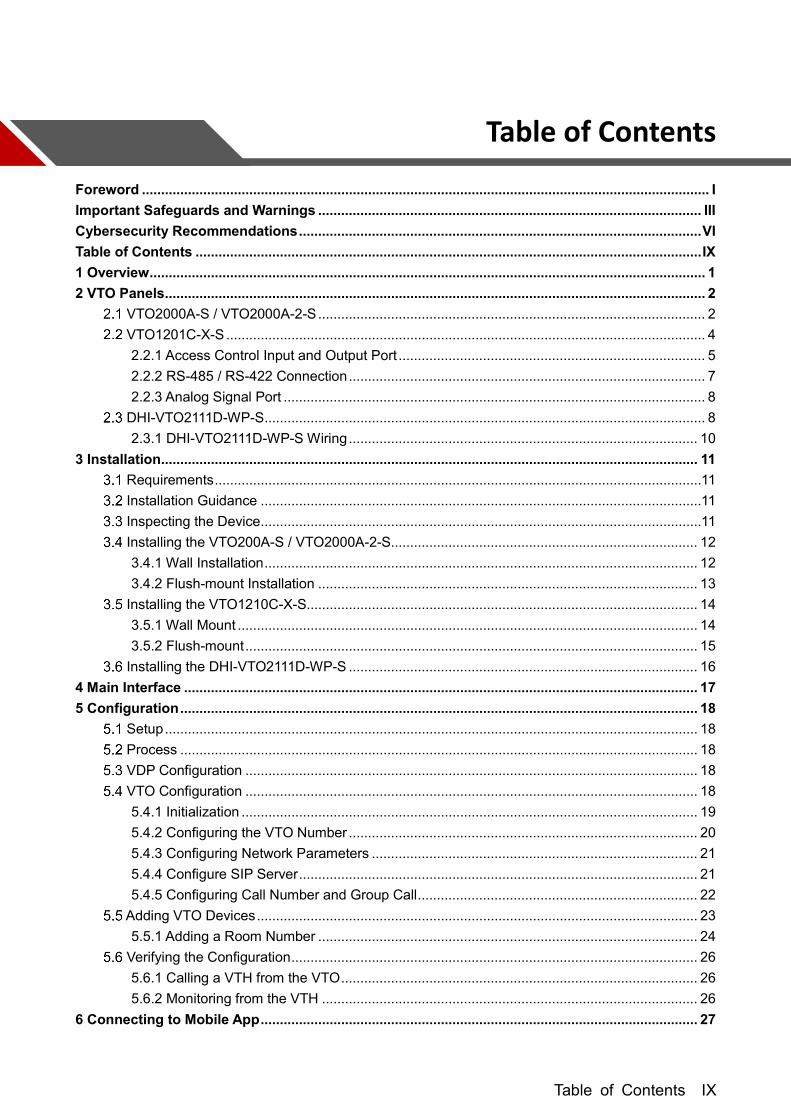
Table of Contents IX
Table of Contents
Foreword .................................................................................................................................................... I Important Safeguards and Warnings .................................................................................................... III Cybersecurity Recommendations ......................................................................................................... VI Table of Contents .................................................................................................................................... IX 1 Overview ................................................................................................................................................. 1 2 VTO Panels ............................................................................................................................................. 2
VTO2000A-S / VTO2000A-2-S ..................................................................................................... 2 VTO1201C-X-S ............................................................................................................................. 4
2.2.1 Access Control Input and Output Port ................................................................................ 5 2.2.2 RS-485 / RS-422 Connection ............................................................................................. 7 2.2.3 Analog Signal Port .............................................................................................................. 8
DHI-VTO2111D-WP-S ................................................................................................................... 8 2.3.1 DHI-VTO2111D-WP-S Wiring ........................................................................................... 10
3 Installation ............................................................................................................................................ 11 Requirements ............................................................................................................................... 11 Installation Guidance ................................................................................................................... 11 Inspecting the Device ................................................................................................................... 11 Installing the VTO200A-S / VTO2000A-2-S................................................................................ 12
3.4.1 Wall Installation ................................................................................................................. 12 3.4.2 Flush-mount Installation ................................................................................................... 13
Installing the VTO1210C-X-S...................................................................................................... 14 3.5.1 Wall Mount ........................................................................................................................ 14 3.5.2 Flush-mount ...................................................................................................................... 15
Installing the DHI-VTO2111D-WP-S ........................................................................................... 16 4 Main Interface ...................................................................................................................................... 17 5 Configuration ....................................................................................................................................... 18
Setup ........................................................................................................................................... 18 Process ....................................................................................................................................... 18 VDP Configuration ...................................................................................................................... 18 VTO Configuration ...................................................................................................................... 18
5.4.1 Initialization ....................................................................................................................... 19 5.4.2 Configuring the VTO Number ........................................................................................... 20 5.4.3 Configuring Network Parameters ..................................................................................... 21 5.4.4 Configure SIP Server ........................................................................................................ 21 5.4.5 Configuring Call Number and Group Call ......................................................................... 22
Adding VTO Devices ................................................................................................................... 23 5.5.1 Adding a Room Number ................................................................................................... 24
Verifying the Configuration .......................................................................................................... 26 5.6.1 Calling a VTH from the VTO ............................................................................................. 26 5.6.2 Monitoring from the VTH .................................................................................................. 26
6 Connecting to Mobile App .................................................................................................................. 27

Table of Contents X
1
1 Overview Dahua VTO Intercom devices allow tenants to view and talk with visitors and remotely unlock doors all from an intuitive mobile app and an interior color indoor monitor. Each outdoor station includes a 1.3 MP wide angle camera with manual rear pivot, two-way talk and enables remote functions such as snapshot when ringing and the ability to record video and audio messages to a VTH series monitor. SIP Compatibility Dahua Intercom devices are compatible with the Session Initiation Protocol version 2.0 (SIP), a signaling protocol for Internet conferencing, telephony, presence, event notification, and instant messaging. SIP is widely used to initiate and terminate Voice Over Internet Protocol (VOIP) calls, as well as connect physical devices to mobile applications. Dahua Intercom devices are ideal for single-family homes as well as large residential complexes or commercial properties.

2
2 VTO Panels Use this process to plan, install, and configure the security network and the IP devices.
VTO2000A-S / VTO2000A-2-S The DHI-VTO2000A-S/VTO2000-A-2-S allows tenants to view and talk with visitors and remotely unlock doors all from an intuitive mobile app and an interior color indoor monitor. Each IP outdoor station includes a 1.3 MP wide angle camera with manual rear pivot, two-way talk and enables remote functions such as snapshot when ringing and the ability to record video and audio messages to a VTH series monitor.
Front Panel
Ref Name Description 1 MIC Inputs audio.
2 Camera Monitors door area.
3 Fill light Provides extra light for the camera.
4 Speaker Outputs audio.
5 Tag slot Put on information as needed.
6 Call button Press to call VTH or the management center.
Table 2-1: VTO2000A-S Front Panel Keys
3
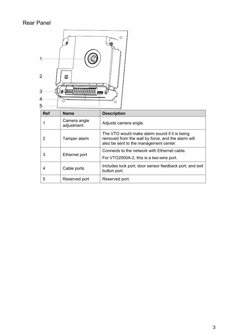
Rear Panel
Ref Name Description
1 Camera angle adjustment Adjusts camera angle.
2 Tamper alarm The VTO would make alarm sound if it is being removed from the wall by force, and the alarm will also be sent to the management center.
3 Ethernet port Connects to the network with Ethernet cable. For VTO2000A-2, this is a two-wire port.
4 Cable ports Includes lock port, door sensor feedback port, and exit button port.
5 Reserved port Reserved port.

4
VTO1201C-X-S
Front Panel
Ref Name Description 1 Microphone Audio input
2 Light Provides extra light for the camera.
3 Speaker Audio outputs.
4 Dialing Area
• *: End the call or delete the previously entered character.
• 0 – 9: Use to enter room number or password. • #: Press to enter the password, then press again to
complete the password. • : : Press to start a phone call. Enter the room
number then press this key to make the call. • : : Press to call the management station.
5 Access card reader Recognizes access cards and unlocks a door.
6 Screen Displays information.
7 Camera Monitors door area.

5
Rear Panel
Ref Name Description
1 Tamper alarm VTO sounds an alarm and sends an alert to the management office if it is being removed from the wall by force.
2 Access output port Used to connect to door locks.
3 Ethernet port Connects to the network via an Ethernet cable.
4 Access input port Used to connect to door locks.
5 Power port Inputs 12V DC power to the VTO.
6 Analog signal port Used to connect VTO to an analog device.
7 RS-485/RS-422 port Used to connect VTO to an RS-485 or an RS-422 device.
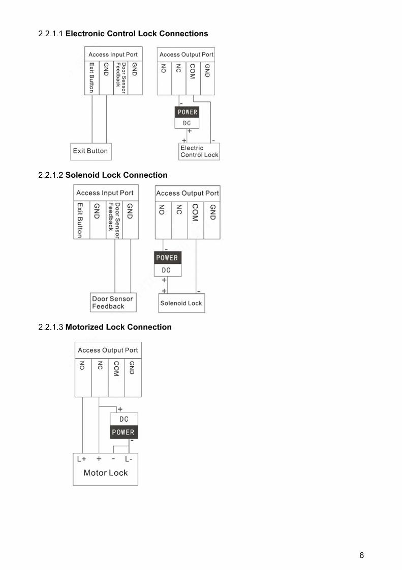
2.2.1 Access Control Input and Output Port Use this port to connect the VTO to door locks. The connection method varies with different locks: Electronic Locks, Solenoid Locks, and Motorized Locks.
6
Electronic Control Lock Connections
Solenoid Lock Connection
Motorized Lock Connection
7
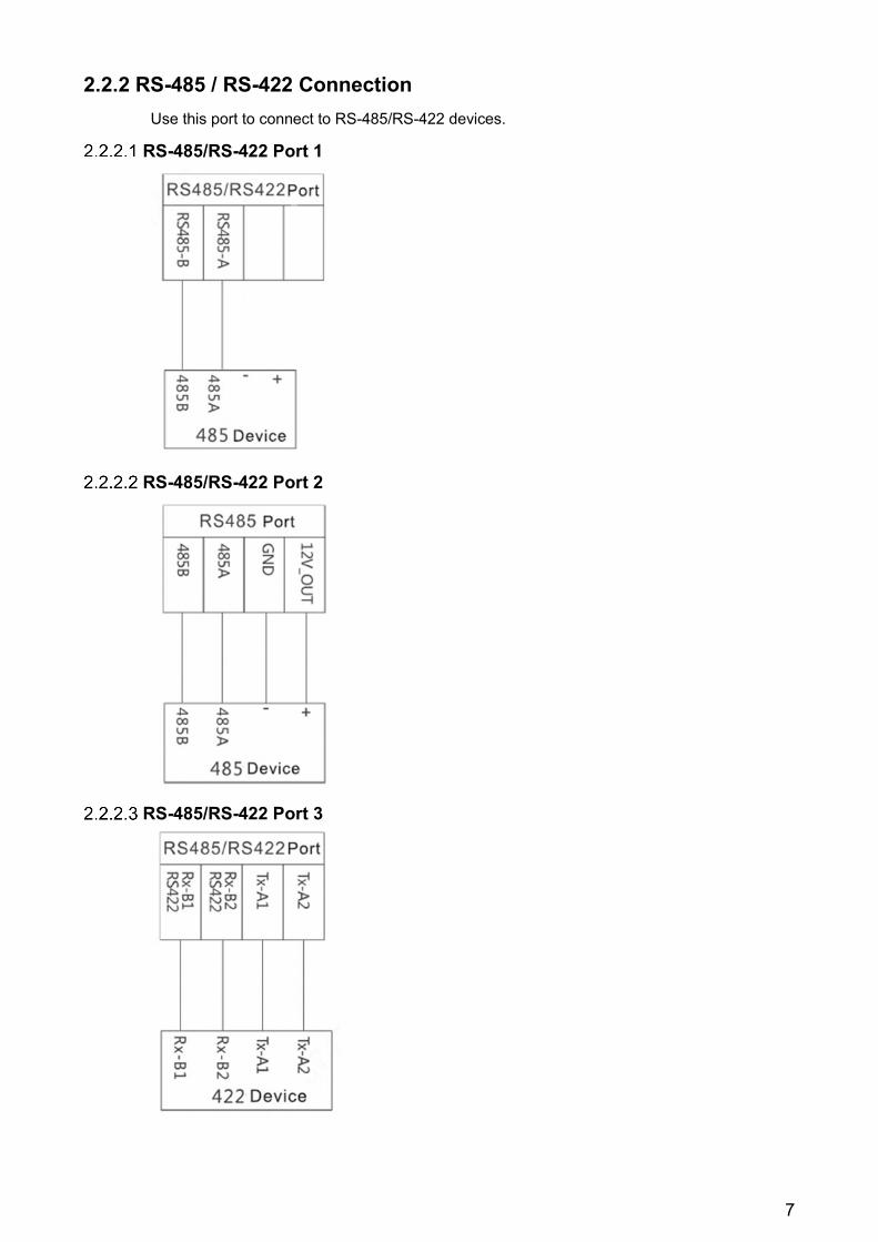
2.2.2 RS-485 / RS-422 Connection Use this port to connect to RS-485/RS-422 devices.
RS-485/RS-422 Port 1
RS-485/RS-422 Port 2
RS-485/RS-422 Port 3

8
2.2.3 Analog Signal Port Use the analog signal port to connect to analog devices.
DHI-VTO2111D-WP-S
Front Panel
Ref Name Description 1 Microphone Audio input.
2 Camera Monitors door area.
3 Access card reader Recognizes access cards and unlocks a door.
4 Indicator Light Steady Blue: Standby status Flashing Blue: Network offline
5 Call Button Call a VTH unit or the management center.
6 Speaker Audio output.

9
Rear Panel
Ref Name Description 1 Bracket Position Bracket used to fix device and wall.
2 Vandal-proof Switch Switch sounds an alarm if the VTO is forcibly removed
from the wall.
3 Alarm Input/output Interface One (1) Channel alarm input
4 RESET Key
• Quick press to reset the WiFi signal. • 10-second press to restore default settings.
5 RJ45 Interface Sandard Ethernet cable for network support and PoE
power input.
6 Power Input Interface
12 VDC power input. Supports 9V-26V wide voltage, with anti-reverse connection.

10
2.3.1 DHI-VTO2111D-WP-S Wiring

11
3 Installation Requirements
Do not install the VTO to places with condensation, high temperature, grease or dust, chemical corrosion, direct sunlight, or zero shelter.
The installation and adjustment must be finished by a professional installer, and do not disassemble the VTO.
Installation Guidance The VTO horizontal angle of view varies with different model, try to face to the center of the VTO as much as possible.
Inspecting the Device Sequence Item Content
1 Overall package
Appearance Check for obvious damage and check that the fittings and hardware are complete. Package
Fittings
2 Model and Label
Device Model Inspect whether it is consistent with order contract.
Label on the device
Inspect whether the label is torn or damaged. Do not discard the label. The warranty is voided if the label is not present.
3 Device Appearance Check for any damage and loose fittings.
Table 3-1: Device Inspection

12
Installing the VTO200A-S / VTO2000A-2-S Install the device in an appropriate location. Installation and commissioning shall be performed by professional integrators trained on
the latest security devices. DO NOT dismantle or repair the device. Contact your local Dahua representative in case
of a faulty device.
3.4.1 Wall Installation Drill screw holes on the wall according to those on the mounting bracket, and then insert
the expansion. Connect the ports on the rear panel to those in the wall through the mounting bracket. Fix the mounting bracket on the wall with ST3×18 screws.
Fix the VTO on the mounting bracket with M3×6 screws.
13
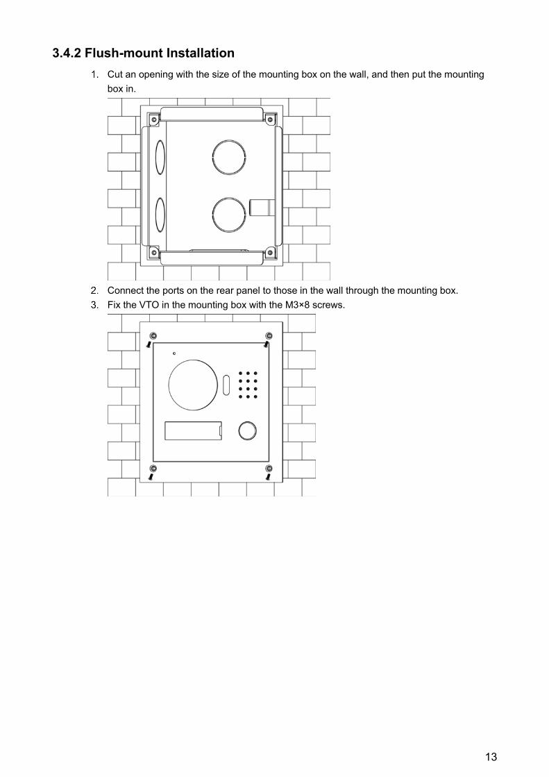
3.4.2 Flush-mount Installation Cut an opening with the size of the mounting box on the wall, and then put the mounting
box in.
Connect the ports on the rear panel to those in the wall through the mounting box. Fix the VTO in the mounting box with the M3×8 screws.
14
Installing the VTO1210C-X-S
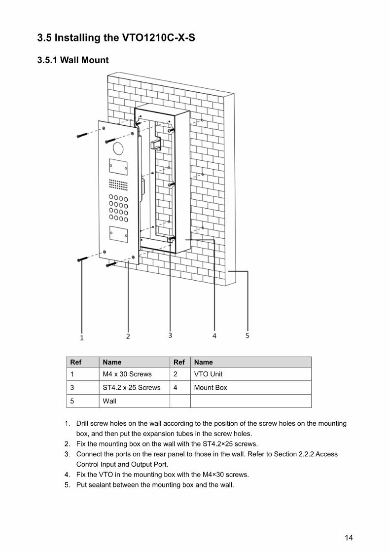
3.5.1 Wall Mount
Ref Name Ref Name 1 M4 x 30 Screws 2 VTO Unit
3 ST4.2 x 25 Screws 4 Mount Box
5 Wall
Drill screw holes on the wall according to the position of the screw holes on the mounting
box, and then put the expansion tubes in the screw holes. Fix the mounting box on the wall with the ST4.2×25 screws. Connect the ports on the rear panel to those in the wall. Refer to Section 2.2.2 Access
Control Input and Output Port. Fix the VTO in the mounting box with the M4×30 screws. Put sealant between the mounting box and the wall.
15
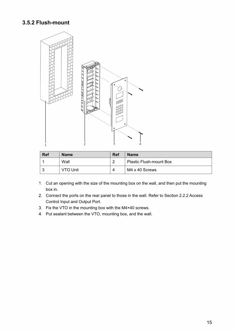
3.5.2 Flush-mount
Ref Name Ref Name 1 Wall 2 Plastic Flush-mount Box
3 VTO Unit 4 M4 x 40 Screws
Cut an opening with the size of the mounting box on the wall, and then put the mounting
box in. Connect the ports on the rear panel to those in the wall. Refer to Section 2.2.2 Access
Control Input and Output Port. Fix the VTO in the mounting box with the M4×40 screws. Put sealant between the VTO, mounting box, and the wall.
16
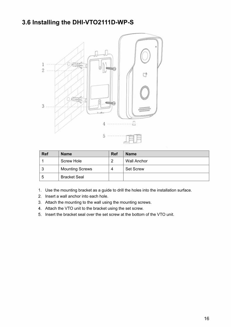
Installing the DHI-VTO2111D-WP-S
Ref Name Ref Name 1 Screw Hole 2 Wall Anchor
3 Mounting Screws 4 Set Screw
5 Bracket Seal
Use the mounting bracket as a guide to drill the holes into the installation surface. Insert a wall anchor into each hole. Attach the mounting to the wall using the mounting screws. Attach the VTO unit to the bracket using the set screw. Insert the bracket seal over the set screw at the bottom of the VTO unit.
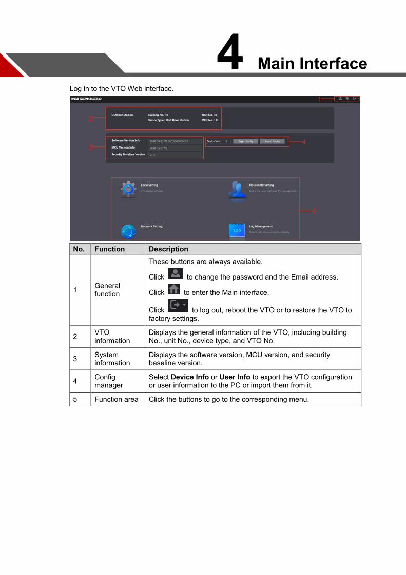
4 Main Interface Log in to the VTO Web interface.
No. Function Description
1 General function
These buttons are always available.
Click to change the password and the Email address.
Click to enter the Main interface.
Click to log out, reboot the VTO or to restore the VTO to factory settings.
2 VTO information
Displays the general information of the VTO, including building No., unit No., device type, and VTO No.
3 System information
Displays the software version, MCU version, and security baseline version.
4 Config manager
Select Device Info or User Info to export the VTO configuration or user information to the PC or import them from it.
5 Function area Click the buttons to go to the corresponding menu.
5 Configuration Confirm that all devices are complete and that they work properly prior to installation and configuration.
Setup Prior to commissioning and configuring the VTO unit, ensure the unit conforms to the following: Check that the unit is connected to the proper power supply. Power on the device only
after the circuit is confirmed to be normal. Plan the list of IP Addresses and the ID numbers for each VTO and VTH unit. Check the deployment position of SIP server. Use the VTO Web interface to set VTO and VTH information. Then set the VTH and VTO
information at each VTH device.
Process Plan IP address for every device, and also plan the unit number and room number you
need. Configure VTO. See "4.3 Configuring VTO."
a) Initialize VTO. b) Configure VTO number. c) Configure VTO network parameters. d) Configure SIP Server. e) Configure target room number and group call. f) Add VTO devices to the SIP server. g) Add room number to the SIP server.
Configure VTH. See the VTH users' manual. Verify Configuration.
VDP Configuration Download the "VDPConfig" application and perform the device initialization, IP address modification, and system upgrading for multiple devices at the same time.
VTO Configuration Connect the VTO to your PC with network cable, and for first time login, you need to create a new password for the web interface.
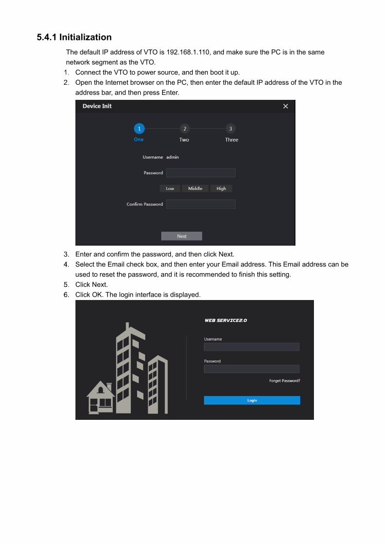
5.4.1 Initialization The default IP address of VTO is 192.168.1.110, and make sure the PC is in the same network segment as the VTO. Connect the VTO to power source, and then boot it up. Open the Internet browser on the PC, then enter the default IP address of the VTO in the
address bar, and then press Enter.
Enter and confirm the password, and then click Next. Select the Email check box, and then enter your Email address. This Email address can be
used to reset the password, and it is recommended to finish this setting. Click Next. Click OK. The login interface is displayed.
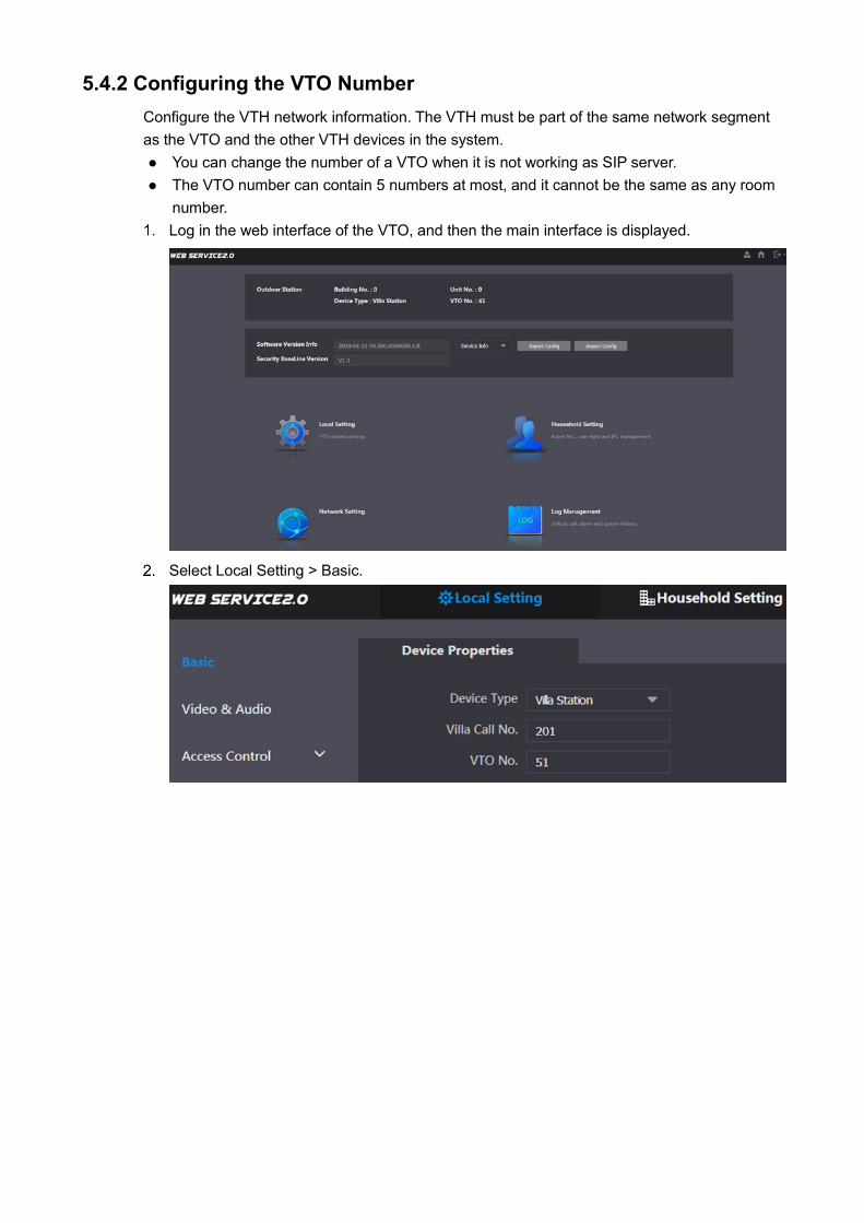
5.4.2 Configuring the VTO Number Configure the VTH network information. The VTH must be part of the same network segment as the VTO and the other VTH devices in the system. You can change the number of a VTO when it is not working as SIP server. The VTO number can contain 5 numbers at most, and it cannot be the same as any room
number. Log in the web interface of the VTO, and then the main interface is displayed.
Select Local Setting > Basic.

In the VTO No. input box, enter the VTO number you planned for this VTO, and then click Confirm to save.
5.4.3 Configuring Network Parameters Select Network Setting > Basic.
Enter the network parameters you planed, and then click Save.
The VTO will reboot, and you need to modify the IP address of your PC to the same network segment as the VTO to log in again.
5.4.4 Configure SIP Server The SIP server is required in the network to transmit intercom protocol, and then all the VTO and VTH devices connected to the same SIP server can make video call between each other. You can use VTO device or other servers as SIP server. Press and hold Setting until the system displays the Password Verification dialog box. Select Network Setting > SIP Server.
Select the server type you need. If the VTO you are visiting works as SIP server:
Select the Enable check box at SIP Server, and then click Save. The VTO will reboot, and after rebooting, you can then add VTO and VTH devices to
this VTO. If the VTO you are visiting does not work as SIP server, do not select the Enable check
box at SIP Server, otherwise the connection will fail: If other VTO works as SIP server. select VTO in the Server Type list, and then
configure the parameters
Set the parameters for the SIP server using the following information. Parameter Description
IP Addr. The IP address of the VTO which works as SIP server.
Port 5060
Username Keep the default value.
Password
SIP Domain VDP
SIP Server Username The user name and password for the web interface of the SIP server. SIP Server Password
Table 4-1: SIP Server Parameters
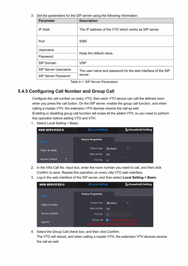
5.4.5 Configuring Call Number and Group Call Configure the call number on every VTO, then each VTO device can call the defined room when you press the call button. On the SIP server, enable the group call function, and when calling a master VTH, the extension VTH devices receive the call as well. Enabling or disabling group call function will erase all the added VTH, so you need to perform this operation before adding VTO and VTH. Select Local Setting > Basic.
In the Villa Call No. input box, enter the room number you need to call, and then click
Confirm to save. Repeat this operation on every villa VTO web interface. Log in the web interface of the SIP server, and then select Local Setting > Basic.
Select the Group Call check box, and then click Confirm. The VTO will reboot, and when calling a master VTH, the extension VTH devices receive the call as well.
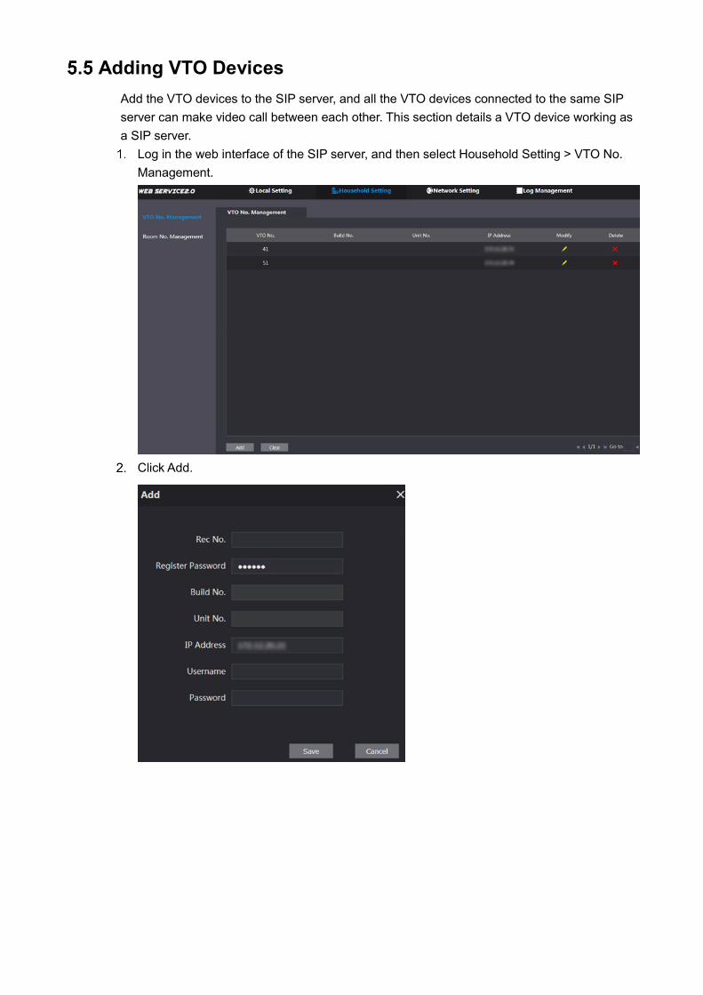
Adding VTO Devices Add the VTO devices to the SIP server, and all the VTO devices connected to the same SIP server can make video call between each other. This section details a VTO device working as a SIP server. Log in the web interface of the SIP server, and then select Household Setting > VTO No.
Management.
Click Add.
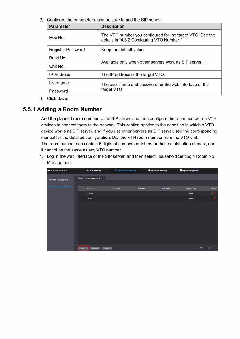
Configure the parameters, and be sure to add the SIP server. Parameter Description
Rec No. The VTO number you configured for the target VTO. See the details in "4.3.2 Configuring VTO Number."
Register Password Keep the default value.
Build No. Available only when other servers work as SIP server.
Unit No.
IP Address The IP address of the target VTO.
Username The user name and password for the web interface of the target VTO Password
Click Save.
5.5.1 Adding a Room Number Add the planned room number to the SIP server and then configure the room number on VTH devices to connect them to the network. This section applies to the condition in which a VTO device works as SIP server, and if you use other servers as SIP server, see the corresponding manual for the detailed configuration. Dial the VTH room number from the VTO unit. The room number can contain 6 digits of numbers or letters or their combination at most, and it cannot be the same as any VTO number. Log in the web interface of the SIP server, and then select Household Setting > Room No.
Management.

Click the Add.
Configure room information.
Parameter Description
Rec No. The VTO number you configured for the target VTO.
First Name
Enter the information you need to differentiate each room. Last Name
Nick Name
Room No.
• If you use multiple VTH devices, the room number of the master VTH should be "room number#0", and the room number of the extension VTH should be "room number#1", "room number#2", and so on.
• You can have 9 extension VTH devices at most for one master VTH.
Register Type Select public, and local is reserved for future use.
Register Password Keep the default value.
Click Save. The added room number is displayed. Click Edit to modify room information, and click Delete to delete a room.
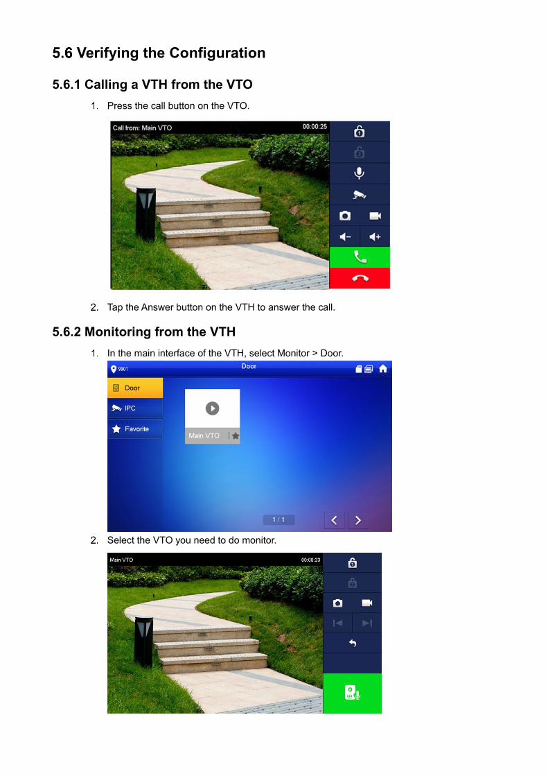
Verifying the Configuration
5.6.1 Calling a VTH from the VTO Press the call button on the VTO.
Tap the Answer button on the VTH to answer the call.
5.6.2 Monitoring from the VTH In the main interface of the VTH, select Monitor > Door.
Select the VTO you need to do monitor.
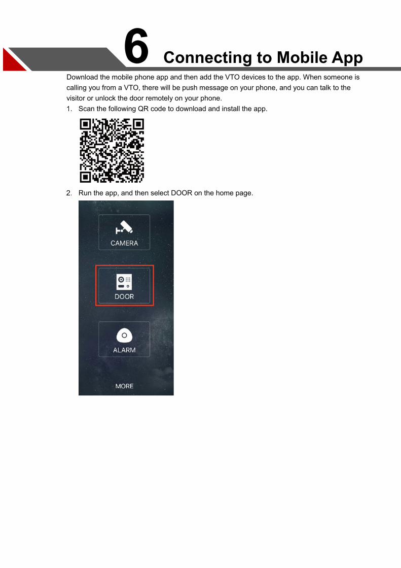
6 Connecting to Mobile App Download the mobile phone app and then add the VTO devices to the app. When someone is calling you from a VTO, there will be push message on your phone, and you can talk to the visitor or unlock the door remotely on your phone.
Scan the following QR code to download and install the app.
Run the app, and then select DOOR on the home page.
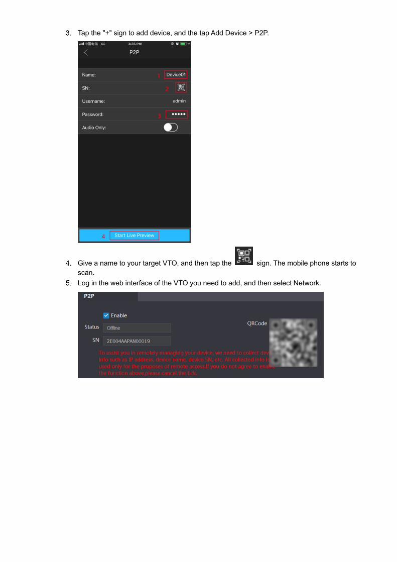
Tap the "+" sign to add device, and the tap Add Device > P2P.
Give a name to your target VTO, and then tap the sign. The mobile phone starts to scan.
Log in the web interface of the VTO you need to add, and then select Network.
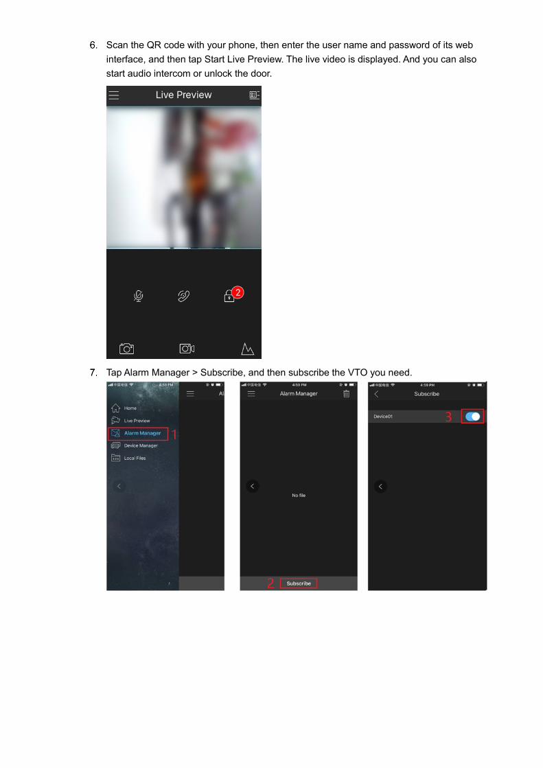
Scan the QR code with your phone, then enter the user name and password of its web interface, and then tap Start Live Preview. The live video is displayed. And you can also start audio intercom or unlock the door.
Tap Alarm Manager > Subscribe, and then subscribe the VTO you need.
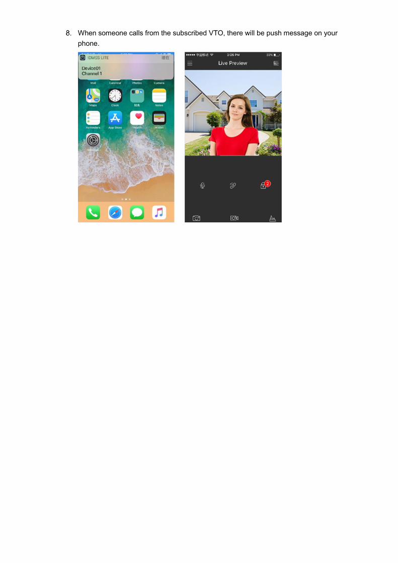
When someone calls from the subscribed VTO, there will be push message on your phone.

Dahua Technology USA 23 Hubble Irvine, CA 92618 Tel: (949) 679-7777 Fax: (949) 679-5760 Support: 877-606-1590 Sales: [email protected] Support: [email protected]