© VTI Instruments Corp. Designing Highly Efficient LXI-based Systems Tom Sarfi, VTI In strumen ts.

VTi® CELTIC MOTOR FOR VERTICAL BLINDSMOTOR VTi® CELTICPARA PERSIANAS VERTICALES
vertilux.com
PROGRAMMING INSTRUCTIONSMANUAL DE PROGRAMACIÓN

PROG
RAM
MIN
G IN
STRU
CTIO
NS
VTi® Celtic Motor for Vertical Blinds
Applies to Item Numbers:6-710-VB-001106-710-VB-00120 Features:
• Designed and manufactured in Europe using the highest quality components
• Slim design and almost fully hidden behind the rail
• Left or right installation options available
• Compatible with strap or scissor carriers
• Draw and tilt action of the slats
• One way & center open fabrication option
• Maximum weight capacity: 8 kg I 17.6 lb
• Maximum rail length: 5.50 m | 18 ft
• DC motor with RF communication through the VTi® Celtic Radio Receiver & Transformer Wall Switch (6-700-AT-AC227)
• Smart control with VTi® Smart Hub
• Compatible with leading brands of Home Automation Systems
ENGLISH
1vertilux.com
2vertilux.com© 2019. Vertilux, Ltd. All Rights Reserved. Last revised: February 2019.
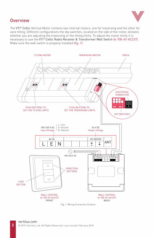
OverviewThe VTi® Celtic Vertical Motor contains two internal motors, one for traversing and the other for vane tilting. Different configurations the dip switches, located on the side of the motor, dictates whether you are adjusting the traversing or the tilting limits. To adjust the motor limits it is necessary to use the VTi® Celtic Radio Receiver & Transformer Wall Switch (6-700-AT-AC227). Make sure the wall switch is properly installed (fig. 1).
TILTING MOTOR TRAVERSING MOTOR
PUSH BUTTONS TO SET THE TILTING LIMITS
PUSH BUTTONS TO SET THE TRAVERSING LIMITS
TRACK
1DIP
ON23
4
DIRECTIONBUTTONS
STOPBUTTON
WALL CONTROL(6-700-AT-AC227)
FRONT
WALL CONTROL(6-700-AT-AC227)
BACKFig. 1. Wiring Connection Scheme
L: LineE: GroundN: Neutral
100-240 V ACInput Voltage
24 V DCOutput Voltage
ELECTRICALCONNECTOR
DIP SWITCHES
1DIP ON
2 3 4
100-240 V AC
3vertilux.com
© 2019. Vertilux, Ltd. All Rights Reserved. Last revised: February 2019.
Setting traversing limitsBefore starting...
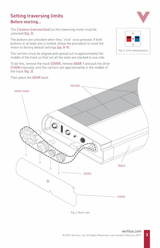
The 2 buttons (red and blue) on the traversing motor must be unlocked (fig. 2).
The buttons are unlocked when they “click” once pressed. If both buttons or at least one is locked, follow the procedure to reset the motor to factory default settings (pp. 8-9). The carriers must be aligned and spread out to approximately the middle of the track so that not all the slats are stacked to one side.
To do this, remove the track COVER, remove GEAR 1 and pull the drive CHAIN manually until the carriers are approximately in the middle of the track (fig. 3).
Then place the GEAR back.
Fig. 3. Motor side
GEARS
TRACK
COVER
DRIVE CHAIN
MOTORS
1
2
3
4
Fig. 2. Limit setting buttons

4vertilux.com© 2019. Vertilux, Ltd. All Rights Reserved. Last revised: February 2019.
TRAVERSING MOTORRED BUTTON
6. Press and hold the red button until you reach step 8.
7. On the wall control, press the opposite direction button of the one selected in step 3.Let the motor move and press the stop button when the slats reach the second traversing desired limit.*
OPPOSITE DIRECTIONBUTTON
STOP BUTTON
5. On the wall control, press the opposite direction button of the one selected in step 3, this will bring the carriers to the initial position (in the middle of the track) in which they first were.The first traversing limit has now been set.
1. Set DIP switches No. 2 and No. 4 in the ON position to set the traversing limits.
2. Press and hold the blue button until you reach step 4.
TRAVERSING MOTORBLUE BUTTON
TRAVERSING MOTORBLUE BUTTON
4. You can now release the blue button.
1DIP ON
2 3 4
OPPOSITE DIRECTIONBUTTON
3. On the wall control, press either direction button. If the button you pressed does not start the traverse movement of the carriers, try the opposite direction button.Press stop button when the carriers reach the first desired limit at one side of the track*.Remember which direction button you selected in this step. DIRECTION BUTTON STOP BUTTON

5vertilux.com
© 2019. Vertilux, Ltd. All Rights Reserved. Last revised: February 2019.
TRAVERSING MOTORRED BUTTON
8. You can now release the red button.On the wall control, press the same direction button as selected in step 3.The other traversing limit has now been set.
DIRECTION BUTTON
9. Set all DIP switches in the OFF position and proceed with the setting of the tilting limits. If the tilting limits are already set, place DIP switch No. 4 in the OFF position and No. 2 in the ON position. Both motors’ limits are now set.
1DIP ON
2 3 4
1. To set the tilting limits, set only DIP switch No. 4 in the ON position.
1DIP ON
2 3 4
Setting tilting limitsBefore starting...
To set the tilting limits, the 2 buttons (red and blue) must be unlocked. The buttons are unlocked when they “click” once pressed. If either button is locked, follow the procedure on pages 8-9 to reset the motor to factory default settings.
The carriers must be spread out to approximately the middle of the track so that not all the slats are stacked to one side. If the traversing limits are already set, put the DIP switch No. 2 and No. 4 in the ON position. Using the wall control, move the slats to the middle of the track, approximately.
The carriers must be aligned and set to 90° of the track in the “open” position (fig. 4). To do this, remove the track COVER, remove GEARS 1, 2 and 3, and rotate manually GEAR 4 until the carriers are aligned and set to 90° of the track. Then place the GEARS back (fig. 3).
Insert a piece of slat or a small card in one of the carriers in order to set the tilting limits precisely. After aligning the carriers, re-asemble the motor.
*If you made a mistake and pressed the stop button when the carriers were not in the desired position, you can readjust their position with the direction buttons as long as you don’t release the button that you have pressed on the motor.
Fig. 5. Slats in 0º
Fig. 4. Slats in 90º
IMPORTANT: Secure the motor settings by covering the limit setting buttons with their cover.

6vertilux.com© 2019. Vertilux, Ltd. All Rights Reserved. Last revised: February 2019.
2. Press and hold the blue button until you reach step 4. TILTING MOTOR
BLUE BUTTON
3. On the wall control, press either direction button. If the button you pressed does not make the carriers rotate, try the opposite direction button. Press the stop button when the carriers are aligned and set at 0° of the track (fully closed position) (fig. 5)*. Remember which direction button you selected in this step.
DIRECTION BUTTON STOP BUTTON
TILTING MOTORRED BUTTON
OPPOSITE DIRECTIONBUTTON
5. On the wall control, press the opposite direction button to make the carriers return to the original starting position at 90° of the rail, (open position) (fig. 4).The first tilting limit has now been set.
4. You can now release the blue button.
TILTING MOTORBLUE BUTTON
6. Press and hold the red button until you reach step 8.
7. Press the opposite direction button of the one selected in step 3.The slats will rotate to the opposite direction of the first tilting limit that was set.Press the stop button when the slat is aligned and set to 0° of the track (fig. 5)*. OPPOSITE DIRECTION
BUTTONSTOP BUTTON
TILTING MOTORRED BUTTON
8. You can now release the red button.On the wall control, press the same direction button as selected in step 3.The other tilting limit has now been set.
DIRECTION BUTTON
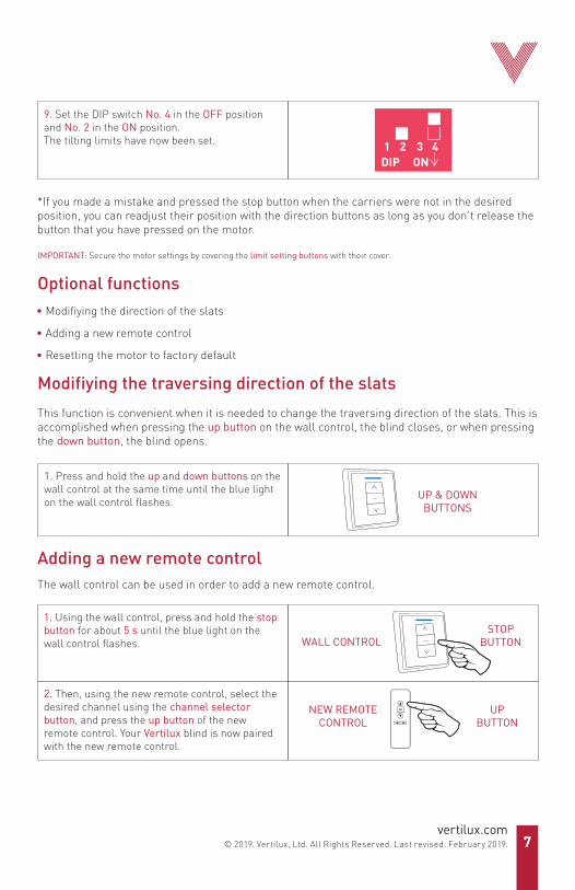
9. Set the DIP switch No. 4 in the OFF position and No. 2 in the ON position.The tilting limits have now been set. 1
DIP ON2 3 4
This function is convenient when it is needed to change the traversing direction of the slats. This is accomplished when pressing the up button on the wall control, the blind closes, or when pressing the down button, the blind opens.
Modifiying the traversing direction of the slats
The wall control can be used in order to add a new remote control.
Adding a new remote control
UP & DOWNBUTTONS
1. Press and hold the up and down buttons on the wall control at the same time until the blue light on the wall control flashes.
2. Then, using the new remote control, select the desired channel using the channel selector button, and press the up button of the new remote control. Your Vertilux blind is now paired with the new remote control.
UPBUTTON
NEW REMOTECONTROL
1. Using the wall control, press and hold the stop button for about 5 s until the blue light on the wall control flashes.
STOPBUTTONWALL CONTROL
Optional functions• Modifiying the direction of the slats
• Adding a new remote control
• Resetting the motor to factory default
*If you made a mistake and pressed the stop button when the carriers were not in the desired position, you can readjust their position with the direction buttons as long as you don’t release the button that you have pressed on the motor.
IMPORTANT: Secure the motor settings by covering the limit setting buttons with their cover.
7vertilux.com
© 2019. Vertilux, Ltd. All Rights Reserved. Last revised: February 2019.

8vertilux.com© 2019. Vertilux, Ltd. All Rights Reserved. Last revised: February 2019.
If you need to reset the tilting motor
Set DIP switch No. 4 in the ON position.Remove GEARS 1, 2 and 3 to release the chain (fig. 3).
Follow the procedure described in either Case #1 or Case #2 depending on your situation.These procedures apply for the traversing as well as the tilting motors.
Case #1: Both motor buttons, the blue and the red one, do not “click” when pressed.
RED OR BLUEBUTTON IS UNLOCKED
OPPOSITE DIRECTIONBUTTON
4. Press and hold the button that is unlocked on the motor until you complete step 5. On the wall control, press the button in the opposite direction to that selected in step 1 and allow the motor to operate until it stops on its own.
RED OR BLUEBUTTON ISUNLOCKED
STOPBUTTON
DIRECTIONBUTTON
1. On the wall control, keep pressing either direction button until the motor stops on its own. If the button you pressed does not start the motor, or if after several minutes the motor does not stop, try the opposite direction button. Remember which direction button you selected in this step.
2. Press the stop button on the wall control.
3. Test the red and blue buttons again. At this point, one of them should be able to make a "click" sound. That button is now unlocked.
Resetting the motor to factory defaultIf you need to reset the traversing motor
Set DIP switches No. 2 and No. 4 in the ON position.Remove GEAR 1 to release the chain. To do this, remove the track COVER and remove GEAR 1 (fig. 3). Follow the procedure described in either Case #1 or Case #2 depending on your situation.These procedures apply for the traversing as well as the tilting motors.

9
The traversing or tilting motor is now set to its factory default settings. Place GEAR 1 back (fig. 3). You can now follow the procedure to adjust the limits (pp. 3-7).
The traversing or tilting motor is now set to its factory default settings. Place GEAR 1 back (fig. 3).You can now follow the procedure to adjust the limits (pp. 3-7).
RED AND BLUEBUTTONS ARE
UNLOCKED
RELEASERED OR BLUE
BUTTON
5. On the wall control, press the stop button and then release the button that was pressed on the motor.
6. Test the red and blue buttons again. At this point, both buttons should be able to emit a "click" sound when pressed. Both buttons are now unlocked, allowing for new limits to be set.
STOPBUTTON
Case #2: Only one of the 2 motor buttons is locked and does not "click" when pressed.
1. Test the red and blue buttons. One of them should make a “click” sound. Press and hold the button that “clicks”, until you complete step 3.
2. On the wall control, keep pressing either direction button until the motor stops on its own. If the button you pressed does not start the motor, or if after several minutes the motor does not stop, try this step again using the opposite direction button to the one previously selected.
3. Press and release the stop button and then release the button that was pressed on the motor.
STOPBUTTON
DIRECTIONBUTTON
RED OR BLUEBUTTON ISUNLOCKED
RELEASERED OR BLUE
BUTTON
4. Test the red and blue buttons again. At this point, both buttons should be able to emit a “click” sound when pressed. Both buttons are now unlocked, allowing for new limits to be set.
RED AND BLUEBUTTONS ARE
UNLOCKED
The values, recommendations and instructions in this manual may vary at any time without previous notice. They are not contractual and can not be used as claim for defective merchandise, order cancellations or returns.The process of transportation of the motor may cause a slight spill of the grease used for the internal lubrication of the motor. This does not affect its operation. Clean the lubricant residues with a dry cloth to avoid stains on the slats or panels during the shade fabrication process.
•
•
IMPORTANT:
For additional information contact your Vertilux representative or Vertilux Authorized Dealer.

MAN
UAL
DE P
ROGR
AMAC
IÓN
Motor VTi® Celtic para Persianas VerticalesAplica a los números de parte:6-710-VB-001106-710-VB-00120 Características:
• Diseñado y fabricado en Europa, utilizando componentes de la más alta calidad
• Diseño compacto, que permite que el motor quede totalmente oculto detrás del riel
• Motores disponibles para instalación a la derecha o a la izquierda del riel
• Compatibles con los sistemas de carritos tipo strap o tijeras
• Acción de desplazamiento y giro de las lamas
• Apertura de las lamas en una dirección (izquierda o derecha) o apertura central
• Capacidad máxima de peso: 8 kg I 17.6 lb
• Longitud máxima del riel: 5.50 m | 18 ft
• Motor DC (corriente directa) con comunicación RF a través del control de pared VTi® Celtic Radio Receiver &Transformer Wall Switch (6-700-AT-AC227)
• Control inteligente desde teléfonos y tabletas a través del VTi® Smart Hub
• Compatible con las marcas líderes del mercado de Domótica y Automatización
ESPAÑOL
10vertilux.com

11vertilux.com© 2019. Vertilux, Ltd. Todos los derechos reservados. Última revisión: Febrero 2019.
IntroducciónEl motor VTi® Celtic para persianas verticales cuenta con dos motores internos, uno que realiza la función de giro de las lamas y otro el desplazamiento transversal de las lamas. Cada motor cuenta con 2 botones de ajuste de límites mecánicos: un botón azul y otro rojo. Cuando el motor se encuentra en sus valores de fábrica, estos botones pueden oprimirse y emitir un sonido de “click”; lo cual indica que ambos botones se encuentran desbloqueados y que el motor no tiene configurados sus límites. Si alguno de los botones se encuentra bloqueado es necesario seguir el procedimiento para reestablecer el motor a sus valores de fábrica (descrito en las páginas 18 y 19) antes de comenzar a configurar los límites. Para el ajuste de los mismos es necesario utilizar el control de pared VTi® Celtic Radio Receiver & Transformer Wall Switch (6-700-AT-AC227). Asegúrese de que se encuentre correctamente instalado (fig. 1).
1DIP
ON23
4
MOTOR QUE REALIZA EL GIRO DE LAS LAMAS
MOTOR QUE REALIZA EL DESPLAZAMIENTO DE LAS LAMAS
BOTONES PARA CONFIGURARLOS LÍMITES DE GIRO
BOTONES PARA CONFIGURARLOS LÍMITES DE DESPLAZAMIENTO
RIEL
Fig. 1. Diagrama de conexión eléctrica
BOTONES DEDIRECCIÓN
BOTÓN DEPARADA
CONTROL DE PARED(6-700-AT-AC227)VISTA FRONTAL
CONTROL DE PARED(6-700-AT-AC227)VISTA POSTERIOR
L: Línea ActivaE: TierraN: Neutro
100-240 V ACVoltaje de Entrada
24 V DCVoltaje de Salida
hacia el Motor
CONECTORELÉCTRICO
INTERRUPTORES DECONFIGURACIÓN
1DIP ON
2 3 4
100-240 V AC

12vertilux.com
© 2019. Vertilux, Ltd. Todos los derechos reservados. Última revisión: Febrero 2019.
Configuración de los límites de desplazamientoAntes de comenzar...
Asegúrese de que los botones rojo y azul del motor que controlan el desplazamiento de las lamas se encuentran “desbloqueados” (fig. 2), de lo contrario debe seguir el procedimiento para restablecer este motor a sus valores de fábrica antes de configurar los límites (págs. 17 y 18).
Asegúrese de que los carritos se encuentren aproximadamente en la mitad del recorrido del riel y no todos apilados hacia un extremo.
Esto puede hacerse de forma manual; desmonte la TAPA del riel del lado del motor, remueva el ENGRANAJE No.1 y hale la CADENA de transmisión hasta que los carritos se desplacen hasta la mitad del riel aproximadamente (fig. 3).
Fig. 3. Vista lateral del motor
ENGRANAJES
RIEL
TAPA
CADENA
MOTORES
1
2
3
4
Fig. 2. Botones paraajustar los límites

5. En el control de pared, presione el botón en la dirección contraria a la seleccionada en el paso 3, esto llevará los carritos a la posición en la que se encontraban (en la mitad del riel). El primer límite de desplazamiento ha quedado configurado.
4. Ahora puede liberar el botón azul.
1. Coloque los interruptores No. 2 y No. 4 en la posición de ON para configurar los límites de desplazamiento.
2. Mantenga presionado el botón azul hasta completar el paso 4. MOTOR DE
DESPLAZAMIENTOBOTÓN AZUL
MOTOR DE DESPLAZAMIENTO
BOTÓN AZUL
3. En el control de pared presione cualquiera de los dos botones de dirección (si el botón que oprimió no acciona el motor, intente con el botón de dirección contraria). Deje mover el motor y presione el botón de parada cuando los carritos alcancen el primer límite de desplazamiento deseado (en un extremo del riel)*. Recuerde cuál botón de dirección seleccionó en este paso.
1DIP ON
2 3 4
BOTÓN DEDIRECCIÓN
BOTÓN DEDIRECCIÓN
BOTÓN DEPARADA
MOTOR DE DESPLAZAMIENTO
BOTÓN ROJO
MOTOR DE DESPLAZAMIENTO
BOTÓN ROJO
8. Ahora puede liberar el botón rojo.En el control de pared, presione el botón en la misma dirección seleccionada en el paso 3. Los límites de desplazamiento han quedado configurados.
6. Mantenga presionado el botón rojo hasta completar el paso 8.
7. En el control de pared, presione el botón en la dirección contraria a la seleccionada en el punto 3. Deje mover el motor y presione el botón de parada cuando los carritos alcancen el segundo límite de desplazamiento deseado (en el otro extremo del riel)*. BOTÓN DE
DIRECCIÓN CONTRARIABOTÓN DE
PARADA
13vertilux.com© 2019. Vertilux, Ltd. Todos los derechos reservados. Última revisión: Febrero 2019.

14vertilux.com
© 2019. Vertilux, Ltd. Todos los derechos reservados. Última revisión: Febrero 2019.
Fig. 5. Lamas en 0º
Fig. 4. Lamas en 90º
Configuración de los límites de giro de las lamasAntes de comenzar... Verifique que los botones rojo y azul del motor que controlan el giro de las lamas se encuentran desbloqueados. Los botones se encuentran desbloqueados si al presionarlos emiten un sonido de “click”. En el caso de que ambos botones o al menos uno se encuentre bloqueado siga el procedimiento para restablecer este motor a sus valores de fábrica (descritos en las páginas 17 y 18) antes de configurar los límites.
Asegúrese de que los carritos se encuentren cerca del centro del riel y no todos apilados en un extremo. Si los límites de desplazamiento ya han sido configurados, coloque el interruptor No. 2 y No. 4 en la posición de encendido y utilice el control de pared para mover los carritos hasta el medio del riel aproximadamente.
Asegúrese de que la ranura de los carritos donde se insertan las lamas se encuentren alineadas 90° con respecto al riel (en esta posición las lamas se encuentran abiertas, fig. 4).
Esto puede hacerse de forma manual; abra la TAPA del riel, remueva los ENGRANAJES No. 1, 2 y 3 y haga rotar manualmente el ENGRANAJE No. 4 hasta que la ranura donde se insertan las lamas se encuentre 90° con respecto al riel. Luego vuelva a colocar los engranajes (fig. 3).
Se recomienda que inserte una lama o tarjeta pequeña en uno de los carritos durante la configuración de los límites de giro. Esto le facilitará la comprensión del procedimiento de ajuste de los límites.
*Si cometió un error y presionó el botón de parada cuando los carritos no se encontraban en la posición deseada, puede reajustar su posición con los botones de dirección mientras no libere el botón que tiene oprimido en el motor.
9. Coloque todos los interruptores en la posición de APAGADO. Continúe con la configuración de los límites de giro. Si los límites de giro ya se encuentran configurados coloque entonces el interruptor No. 4 en la posición de APAGADO y el No. 2 en la posición de ENCENDIDO. Esta es la configuración en la que deben quedar los interruptores cuando ambos motores se encuentran configurados.
1DIP ON
2 3 4
IMPORTANTE: Asegúrese de cubrir con su tapa los botones de ajuste de límites del motor.

15vertilux.com© 2019. Vertilux, Ltd. Todos los derechos reservados. Última revisión: Febrero 2019.
1. Coloque solo el interruptor No. 4 en la posición de ON para configurar los límites de giro. 1
DIP ON2 3 4
MOTOR DE GIROBOTÓN ROJO
BOTÓN DE DIRECCIÓNCONTRARIA
5. En el control de pared, presione el botón en la dirección contraria a la seleccionada en el paso 3, los carritos rotarán hasta la posición inicial en la cual se encontraban (alineados 90° con respecto al riel, fig. 4). El primer límite de giro ha quedado configurado.
4. Ahora puede liberar el botón azul.
2. Mantenga presionado el botón azul hasta completar el paso 4. MOTOR DE GIRO
BOTÓN AZUL
MOTOR DE GIROBOTÓN AZUL
3. En el control de pared presione cualquiera de los dos botones de dirección (si el botón que oprimió no acciona el motor, intente con el botón de dirección contraria). Presione el botón de parada cuando los carritos roten hasta alcanzar la posición de 0º respecto al riel (lamas cerradas, fig. 5)*.Recuerde cuál dirección seleccionó en este paso.
6. Mantenga presionado el botón rojo hasta completar el paso 8.
BOTÓN DE DIRECCIÓN
BOTÓN DE PARADA
7. En el control de pared, presione el botón en la dirección contraria a la seleccionada en el punto 3. Deje mover el motor y presione el botón de parada cuando los carritos alcancen el segundo límite de giro deseado 0º (fig. 5).
BOTÓN DEDIRECCIÓN CONTRARIA
BOTÓN DE PARADA
8. Ahora puede liberar el botón rojo.En el control de pared, presione el botón en la misma dirección seleccionada en el paso 3.
MOTOR DE GIROBOTÓN ROJO
BOTÓN DE DIRECCIÓN

16vertilux.com
© 2019. Vertilux, Ltd. Todos los derechos reservados. Última revisión: Febrero 2019.
2. Utilizando el nuevo control remoto, seleccione el canal deseado usando los botones de selección de canales, y presione el botón subida.El motor ahora se encuentra configurado en el nuevo control remoto.
BOTÓN DESUBIDA
NUEVO CONTROLREMOTO
Esta función es conveniente cuando la dirección de desplazamiento de las lamas necesita ser cambiada; es decir, cuando al presionar el botón de subida, la persiana comienza a cerrarse, o cuando al presionar el botón de bajada la persiana comienza a abrirse.
Modificar la dirección de desplazamiento de las lamas
Se puede utilizar el control de pared para agregar un nuevo control remoto.
Adicionar un nuevo control remoto
Funciones opcionales• Modificar la dirección de desplazamiento de las lamas
• Adicionar un nuevo control remoto
• Configurar el motor a sus valores de fábrica
1. Mantenga presionado el botón de subida y bajada en el control de pared al mismo tiempo hasta que la luz azul en el control de pared parpadee.
BOTÓN DESUBIDA Y BAJADA
1. Utilizando el control de pared, mantenga presionado el botón de parada por aproximadamente 5 s hasta que la luz azul en el control de pared parpadee.
BOTÓN DEPARADA
CONTROLDE PARED
9. Coloque el interruptor No. 4 en la posición de OFF y el No. 2 en la posición de ON. Los límitesde giro han quedado configurados. 1
DIP ON2 3 4
*Si cometió un error y presionó el botón de parada cuando los carritos no se encontraban en la posición deseada, puede reajustar su posición con los botones de dirección mientras no libere el botón que tiene oprimido en el motor.
IMPORTANTE: Asegúrese de cubrir con su tapa los botones de ajuste de límites del motor
17vertilux.com© 2019. Vertilux, Ltd. Todos los derechos reservados. Última revisión: Febrero 2019.
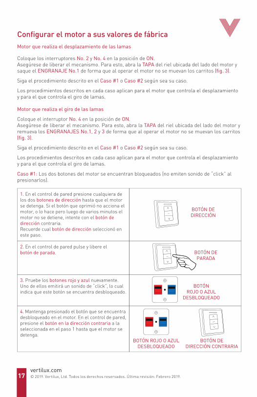
Configurar el motor a sus valores de fábricaMotor que realiza el desplazamiento de las lamas
Coloque los interruptores No. 2 y No. 4 en la posición de ON.Asegúrese de liberar el mecanismo. Para esto, abra la TAPA del riel ubicada del lado del motor y saque el ENGRANAJE No.1 de forma que al operar el motor no se muevan los carritos (fig. 3).
Siga el procedimiento descrito en el Caso #1 o Caso #2 según sea su caso.
Los procedimientos descritos en cada caso aplican para el motor que controla el desplazamiento y para el que controla el giro de lamas.
Motor que realiza el giro de las lamas
Coloque el interruptor No. 4 en la posición de ON. Asegúrese de liberar el mecanismo. Para esto, abra la TAPA del riel ubicada del lado del motor y remueva los ENGRANAJES No.1, 2 y 3 de forma que al operar el motor no se muevan los carritos (fig. 3).
Siga el procedimiento descrito en el Caso #1 o Caso #2 según sea su caso.
Los procedimientos descritos en cada caso aplican para el motor que controla el desplazamiento y para el que controla el giro de lamas.
Caso #1: Los dos botones del motor se encuentran bloqueados (no emiten sonido de “click” al presionarlos).
1. En el control de pared presione cualquiera de los dos botones de dirección hasta que el motor se detenga. Si el botón que oprimió no acciona el motor, o lo hace pero luego de varios minutos el motor no se detiene, intente con el botón de dirección contraria.Recuerde cual botón de dirección seleccionó en este paso.
2. En el control de pared pulse y libere el botón de parada.
3. Pruebe los botones rojo y azul nuevamente. Uno de ellos emitirá un sonido de “click”, lo cual indica que este botón se encuentra desbloqueado.
BOTÓN DEDIRECCIÓN
BOTÓN DEPARADA
BOTÓNROJO O AZUL
DESBLOQUEADO
4. Mantenga presionado el botón que se encuentra desbloqueado en el motor. En el control de pared, presione el botón en la dirección contraria a la seleccionada en el paso 1 hasta que el motor se detenga.
BOTÓN ROJO O AZULDESBLOQUEADO
BOTÓN DEDIRECCIÓN CONTRARIA

18
Caso #2: Solo uno de los dos botones del motor se encuentra bloqueado (no emite sonido de “click” al presionarlo).
El motor ha sido configurado a sus valores de fábrica. Coloque nuevamente el ENGRANAJE y siga el procedimiento para ajustar los límites (págs. 13-16).
El motor ha sido configurado a sus valores de fábrica. Coloque nuevamente el ENGRANAJE y siga el procedimiento para ajustar los límites (págs. 13-17).
5. En el control de pared presione el botón de parada y luego libere el botón que tenía presionado en el motor.
6. Pruebe los botones rojo y azul nuevamente. En este momento los dos botones deben emitirun sonido de “click” al presionarlos, lo cual indica que ambos botones se encuentran desbloqueados y el motor no tiene ningún límite configurado.
BOTONESROJO Y AZUL
DESBLOQUEADOS
BOTÓN DEPARADA
BOTÓN ROJO O AZUL
1. Verifique cual de los dos botones de ajuste de límites del motor se encuentra desbloqueado. Manténgalo presionado hasta completar el paso 3.
BOTÓNROJO O AZUL
DESBLOQUEADO
2. En el control de pared presione cualquiera de los dos botones de dirección hasta que el motor se detenga. Si el botón que presionó no acciona el motor, o lo hace pero luego de varios minutos el motor no se detiene, intente nuevamente este paso con el botón de dirección contraria al seleccionado anteriormente.
BOTÓN DEDIRECCIÓN
4. Pruebe los botones rojo y azul nuevamente. En este momento los dos botones deben emitir un sonido de “click” al presionarlos, lo cual indica que ambos botones se encuentran desbloqueados y el motor no tiene ningún límite configurado.
BOTONESROJO Y AZUL
DESBLOQUEADOS
3. Presione el botón de parada y luego libere el botón que tenía presionado en el motor.
BOTÓNROJO O AZUL
BOTÓN DEPARADA
Los valores, recomendaciones e instrucciones en este manual pueden variar en cualquier momento sin previo aviso. Los mismos no son contractuales y no pueden ser utilizados como reclamo para mercancía defectuosa, cancelaciones de pedidos o devoluciones.Considere que durante la transportación, puede haber un ligero derrame de la grasa utilizada para la lubricación interna del motor. Esto no afecta el funcionamiento del motor. Limpie los residuos de lubricante con un paño seco para evitar manchas en los slats o paneles durante la fabricación de la cortina.
•
•
IMPORTANTE:
Para información adicional contacte a un representante de Vertilux o un distribuidor autorizado.