VT8600 Series Installation Guide - Viconics · VT8600 Series Installation Guide Rooftop Unit and...
11
VT8600 Series Installation Guide Rooftop Unit and Indoor Air Quality Controller CONTENTS Installation 2 Configurable BI/UI Universal Inputs Overview 3 Setup Screen Display 3 Terminal Identification & Function 4 Terminal identification 4 Typical Applications 5 2H / 2C 5 2C / Mod. heat 6 Remote Sensor Accessories 7 Wiring example of single remote room sensor 7 Wiring examples of 2 remote room sensors 8 Wiring examples of 3 remote room sensors 9 Home Screen Display 10 How to Enter Setup Screen 11
Transcript of VT8600 Series Installation Guide - Viconics · VT8600 Series Installation Guide Rooftop Unit and...

VT8600 Series Installation GuideRooftop Unit and Indoor Air Quality Controller
CONTENTSInstallation 2Configurable BI/UI Universal Inputs Overview 3Setup Screen Display 3Terminal Identification & Function 4 Terminal identification 4Typical Applications 5 2H / 2C 5 2C / Mod. heat 6Remote Sensor Accessories 7 Wiring example of single remote room sensor 7 Wiring examples of 2 remote room sensors 8 Wiring examples of 3 remote room sensors 9Home Screen Display 10How to Enter Setup Screen 11

Viconics Technologies Inc. | 9245 Langelier Blvd. | St.-Leonard | Quebec | Canada | H1P 3K9 | Tel: (514) 321-5660 | Fax: (514) 321-4150
028-0435-00 www.viconics.com December 2014
VT8600 SeriesInstallation Guide2
© 2
014
Vic
onic
s Te
chno
logi
es. A
ll rig
hts
rese
rved
.
• If replacing an existing thermostat, label wires before removal of Controller.
• Electronic controls are static sensitive devices. Discharge yourself correctly before manipulating and installing Controller.
• A short circuit or wrong wiring may permanently damage Controller or equipment.
• All VT8600 ® series controls are designed for use as operating controls only and are not safety devices. Tampering with the devices or unintended application of the devices will result in a void of warranty.
• This device must be installed to provide a separation distance of at least 8 in (40 cm) from all persons and must not be collocated or operating in conjunction with any other antenna or transmitter.
Figure-1 Open the cover
Figure-2 Install the base
Figure-3 Reinstall cover
INSTALLATION Preparation
• Remove the security screw (if any) on the bottom of the Terminal Equipment Controller cover.
• Open unit by pulling on bottom side of the Terminal Equipment Controller (Fig. 1).
• Read FCC ID and IC label installed in cover before installing any wireless product.
• Ensure correct side of base faces up.
Location
1. Do not install on outside wall.
2. Do not install in areas with direct heat source.
3. Do no install near any air discharge grill.
4. Do not install in areas exposed to direct sunlight.
5. Ensure Controller has sufficient air circulation.
6. Ensure wall surface is flat and clean.
Installation
1. Pull cables 15 cm ( 6” ) out from wall.
2. Align base and mark location of two mounting holes on wall.
3. Install anchors in wall.
4. Insert cable in central hole of base.
5. Insert screws in mounting holes on each side of base.
6. Strip each wire 1/4” ( 0.6 cm) from end.
7. Insert each wire and screw according to wiring chart (next page).
8. Gently push excess wiring back into hole.
9. Gently align cover to top of base and snap in place from bottom.
10. Install security screw.

VT8600 SeriesInstallation Guide 3
Viconics Technologies Inc. | 9245 Langelier Blvd. | St.-Leonard | Quebec | Canada | H1P 3K9 | Tel: (514) 321-5660 | Fax: (514) 321-4150
028-0435-00 www.viconics.com December 2014
© 2
014
Vic
onic
s Te
chno
logi
es. A
ll rig
hts
rese
rved
.
CONFIGURABLE BI/UI UNIVERSAL INPUTS OVERVIEW Universal input #16 can be configured for the following binary functions:
1. (None): No function will be associated with the input
2. (Rem NSB): remote NSB timer clock input. The scheduling will now be set as per the binary input. It provides low cost setback operation via a dry contact.
Contact opened = OccupiedContact closed = Unoccupied
3. (Motion NO) and (Motion NC): Advanced PIR occupancy functions using a normally open (NO) or normally closed (NC) remote PIR motion sensor. Occupancy mode is now set as per applied PIR function and configuration. Application information and examples are available on document: APP-PIR-VT8xxx. This document will provide the installers and system designers with detailed examples on applications, parameter configuration information, sequence of operation, troubleshooting and diagnostic help required for the proper usage of the onboard PIR sensor.
4. (Window) EMS: Forces the system to disable any current heating or cooling action by the Terminal Equipment Controller. The mode stays the same and the current setpoints are the same occupied setpoints. Only the outputs are disabled. There is a Door/Window alarm displayed on the Terminal Equipment Controller to indicate to the local tenant that the door/window needs to be closed for cooling or heating to resume. Use NC contact.
Contact opened = System disabled with local Window alarmContact closed = System enabled
5. (Fan lock): a Fan lock alarm short text message will be displayed on the Terminal Equipment Controller screen when the input is not energized. Used in conjunction with a local airflow sensor connected to the input. Locks out the Terminal Equipment Controller heating and cooling action if no airflow is detected 10 seconds after the fan ( G terminal ) is energized.
Contact opened = no airflowContact closed = airflow present
Universal input #17 can be configured for the following binary functions:
1. (None): No function will be associated with the input. Input can be used for remote network monitoring.
2. (Door Dry) Door contact & Motion detector: This configuration is only functional if binary input #1 is set to Motion NO or Motion NC or an onboard PIR sensor is used. With this sequence enabled, the occupancy is now dictated through those 2 inputs. Any motion detected will set the zone to occupied status. The zone will remain permanently in occupied mode until the door contact switch opens momentarily. The Terminal Equipment Controller will then go in stand-by mode. If more movements are detected, the occupied mode will resume. While the door is opened, any movements detected by the remote PIR sensor or the onboard PIR sensor will be ignored. Use a Normally Closed contact switching device.
Contact opened = Door openedContact closed = Door closed
3. (Override): Temporary override remote contact. Disables all override menu function of the Terminal Equipment Controller. The override function is now controlled by a manual remote momentarily closed contact. When configured in this mode, the input operates in a toggle mode. With this function enabled it is now possible to toggle between unoccupied & occupied setpoints for the amount of time set by parameter (TOccTime) temporary occupancy time. When Override is enabled, an Override status message will be displayed
4. (Filter): a Filter alarm short text message will be displayed on the Terminal Equipment Controller screen when the input is energized
5. (Service): a Service alarm short text message will be displayed on the Terminal Equipment Controller screen when the input is energized

Viconics Technologies Inc. | 9245 Langelier Blvd. | St.-Leonard | Quebec | Canada | H1P 3K9 | Tel: (514) 321-5660 | Fax: (514) 321-4150
028-0435-00 www.viconics.com December 2014
VT8600 SeriesInstallation Guide4
© 2
014
Vic
onic
s Te
chno
logi
es. A
ll rig
hts
rese
rved
.
VT86xxU
Description / ApplicationUsed in applications
IAQ & RTU
Internal Temperature X
1- BO1 Aux
2- BO2 Y2
3- BO3 Y1
4- BO4 G
5- RC RC (24 Vac)
6- C Common
7- RH RH
8- BO8 W1
9- UO9 W2
10- UO10 Econo (0-10 Vdc)
11- UO11 Heat (0-10 Vdc)
12- UO12 UO12 (Optional 0-10 Vdc output, can be set from BACnet)
13- RS485 + BACnet (+)
14- RS485 - BACnet (-)
15- RS485 Ref BACnet Ref.
16- UI16 UI16 (multifunction input)
17- UI17 UI17 (multifunction input)
18 Scom Common
19- UI19 CO2 (0-10 Vdc input)
20- UI20 RS (Remote sensor input 10K thermistor)
21 Scom Common
22- UI22 SS (Supply sensor input 10K thermistor)
23- UI23 OS (Outside sensor input 10K thermistor)
24- UI24 Airflow (0-10 Vdc input)
TERMINAL IDENTIFICATION & FUNCTION
Terminal identification

VT8600 SeriesInstallation Guide 5
Viconics Technologies Inc. | 9245 Langelier Blvd. | St.-Leonard | Quebec | Canada | H1P 3K9 | Tel: (514) 321-5660 | Fax: (514) 321-4150
028-0435-00 www.viconics.com December 2014
© 2
014
Vic
onic
s Te
chno
logi
es. A
ll rig
hts
rese
rved
.
TYPICAL APPLICATIONS
VT8600
BO
1 -
Aux
BO
2 -
Y2
BO
3 -
Y1
BO
4 -
G
RC
(24
Vac)
C (C
omm
on)
RH
BO
8 -
W1
UO
9 -
W2
UO
10
- E
cono
UO
11
- H
eat
UO
12
BA
Cne
t +
BA
Cne
t -
BA
Cne
t RE
F
UI 1
6
UI 1
7
Com
mon
UI 1
9 -
CO
2
UI 2
0 -
RS
Com
mon
UI 2
2 -
SS
UI 2
3 -
OS
UI 2
4 -
Air
flow
2 Heating Stages / 2 Cooling Stages
13 14 15 16 17 18
7 8 9 10 11 12
19 20 21 22 23 24
1 2 3 4 5 6
ECONO
W2 W1 C R G Y1 Y2
C RCO2
TRANSMITTER(0-10 VDC)
OUT
C OUT
R AIR FLOW
MEASURING STATION (0-10 VDC)
FILTERDPS
SATSENSOR
OATSENSOR

Viconics Technologies Inc. | 9245 Langelier Blvd. | St.-Leonard | Quebec | Canada | H1P 3K9 | Tel: (514) 321-5660 | Fax: (514) 321-4150
028-0435-00 www.viconics.com December 2014
VT8600 SeriesInstallation Guide6
© 2
014
Vic
onic
s Te
chno
logi
es. A
ll rig
hts
rese
rved
.
13 14 15 16 17 18
7 8 9 10 11 12
VT8600
BO
1 -
Aux
BO
2 -
Y2
BO
3 -
Y1
BO
4 -
G
RC
(24
Vac)
C (C
omm
on)
RH
BO
8 -
W1
UO
9 -
W2
UO
10
- E
cono
UO
11
- H
eat
UO
12
BA
Cne
t +
BA
Cne
t -
BA
Cne
t RE
F
UI 1
6
UI 1
7
Com
mon
UI 1
9 -
CO
2
UI 2
0 -
RS
Com
mon
UI 2
2 -
SS
UI 2
3 -
OS
UI 2
4 -
Air
flow
2 Cooling Stages / Modulating Heat
19 20 21 22 23 24
1 2 3 4 5 6
ECONO
C R G Y1 Y2
C RCO2
TRANSMITTER(0-10 VDC)
OUT
C OUT
R AIR FLOW
MEASURING STATION (0-10 VDC)
FILTERDPS
SATSENSOR
OATSENSOR
Mod. Heat(0-10 VDC)

VT8600 SeriesInstallation Guide 7
Viconics Technologies Inc. | 9245 Langelier Blvd. | St.-Leonard | Quebec | Canada | H1P 3K9 | Tel: (514) 321-5660 | Fax: (514) 321-4150
028-0435-00 www.viconics.com December 2014
© 2
014
Vic
onic
s Te
chno
logi
es. A
ll rig
hts
rese
rved
.
REMOTE SENSOR ACCESSORIES
Model no. Description
S3010W1000 Wall mounted temperature sensor
S3020W1000 Wall mounted temperature sensor with override button and occupancy status LED
Note:If one or multiple sensor(s) is/are connected into the RS terminal, the internal temperature sensor is automatically disabled. Dis-connecting the sensor(s) in RS terminal will re-activate the internal sensor.
Remote mount temperature sensors inputs use 10K type 2 NTC thermistors.
Features:• Each sensor can be configured for various averaging combinations• Optional occupancy led• Optional override key
Wiring example of single remote room sensor:
VT8600Series Controller
1xS3020W1000Remote wiring 1 sensorS2-1= On, S2-2=On
S3010W1000Remote wiring 1 sensorS2-1= On, S2-2=On
SCom
RS
Aux
C
DI
OR
Dip switch setting for 1 sensorS2-1= On, S2-2=On
SCom
RS
Common
UI 20 - RS
B0 1 - AUX
C (Common)
UI 16
UI 17
ON
1 2or

Viconics Technologies Inc. | 9245 Langelier Blvd. | St.-Leonard | Quebec | Canada | H1P 3K9 | Tel: (514) 321-5660 | Fax: (514) 321-4150
028-0435-00 www.viconics.com December 2014
VT8600 SeriesInstallation Guide8
© 2
014
Vic
onic
s Te
chno
logi
es. A
ll rig
hts
rese
rved
.
Wiring examples of 2 remote room sensors for averaging applications:
VT8600Series Controller
2xS3010W1000Remote wiring 2 sensorsS2-1= Off, S2-2=On
SCom
RS
Aux
C
DI
SCom
RS
Common
UI 20 - RS
B0 1 - AUX
C (Common)
UI 16
UI 17
VT8600Series Controller
2xS3020W1000Remote wiring 2 sensorsS2-1= Off, S2-2=On
SCom
RS
Aux
C
DI
SCom
RS
Aux
C
DI
VT8600Series Controller
1xS3010W1000 and 1x2xS3020W1000Remote wiring 2 sensorsS2-1= Off, S2-2=On
SCom
RS
Aux
C
DI
SCom
RS
Note for averaging applications:S3010W1000 and S3020W1000 can be mixedmatched.
S3010W1000 and S3020W1000 are to be wiredin parallel.
Respect the Dip switch setting in each remotesensor.
Common
UI 20 - RS
B0 1 - AUX
C (Common)
UI 16
UI 17
Common
UI 20 - RS
B0 1 - AUX
C (Common)
UI 16
UI 17 Dip switch setting for 2 sensorsS2-1= Off, S2-2=On
ON
1 2
or
or
or

VT8600 SeriesInstallation Guide 9
Viconics Technologies Inc. | 9245 Langelier Blvd. | St.-Leonard | Quebec | Canada | H1P 3K9 | Tel: (514) 321-5660 | Fax: (514) 321-4150
028-0435-00 www.viconics.com December 2014
© 2
014
Vic
onic
s Te
chno
logi
es. A
ll rig
hts
rese
rved
.
Wiring examples of 3 remote room sensors for averaging applications:
VT8600Series Controller
2xS3010W1000 and 1xS3020W1000 Remote wiring 3 sensorsS2-1= Off, S2-2=On
SCom
RS
Aux
C
DI
SCom
RS
SCom
RS
VT8600Series Controller
1xS3010W1000 and 2xS3020W1000 Remote wiring 3 sensorsS2-1= Off, S2-2=On
SCom
RS
Aux
C
DI
SCom
RS
Aux
C
DI
SCom
RS
Common
UI 20 - RS
B0 1 - AUX
C (Common)
UI 16
UI 17
Common
UI 20 - RS
B0 1 - AUX
C (Common)
UI 16
UI 17
Dip switch setting for 3 sensorsS2-1= Off, S2-2=Off
ON
1 2
Dip switch setting for 3 sensorsS2-1= Off, S2-2=Off
ON
1 2
Temperature vs. resistance chart for 10 Kohm NTC thermistor (R25°C = 10KΩ±3%, B25/85°C = 3975K±1.5%)
ºC ºF Kohm ºC ºF Kohm ºC ºF Kohm ºC ºF Kohm ºC ºF Kohm
-40 -40 324.3197 -20 -4 94.5149 0 32 32.1910 20 68 12.4601 40 104 5.3467
-35 -31 234.4009 -15 5 71.2430 5 41 25.1119 25 77 10.0000 45 113 4.3881
-30 -22 171.3474 -10 14 54.1988 10 50 19.7390 30 86 8.0694 50 122 3.6202
-25 -13 126.6109 -5 23 41.5956 15 59 15.6286 35 95 6.5499 55 131 3.0016
or
or

Viconics Technologies Inc. | 9245 Langelier Blvd. | St.-Leonard | Quebec | Canada | H1P 3K9 | Tel: (514) 321-5660 | Fax: (514) 321-4150
028-0435-00 www.viconics.com December 2014
VT8600 SeriesInstallation Guide10
© 2
014
Vic
onic
s Te
chno
logi
es. A
ll rig
hts
rese
rved
.
HOME SCREEN DISPLAY
Note: User HMI is configurable and allows display functions such as Outdoor Temperature, Setpoint, and other buttons to be enabled or disabled by setting various parameters in the setup screens.
TimeSystem Status
Fan Status
Up ArrowIncrease Temperature Setpoint
Actual Setpoint
Down ArrowDecrease Temperature Setpoint
Help
Language Selection
Temperature Units
Fan Mode
Date
Occupancy Status
Indoor Temperature
Outdoor Temperature
System Mode
Short Network Message
Typical Hospitality User Interface Shown
VT8600 SeriesInstallation Guide 11
Viconics Technologies Inc. | 9245 Langelier Blvd. | St.-Leonard | Quebec | Canada | H1P 3K9 | Tel: (514) 321-5660 | Fax: (514) 321-4150
028-0435-00 www.viconics.com December 2014
© 2
014
Vic
onic
s Te
chno
logi
es. A
ll rig
hts
rese
rved
.
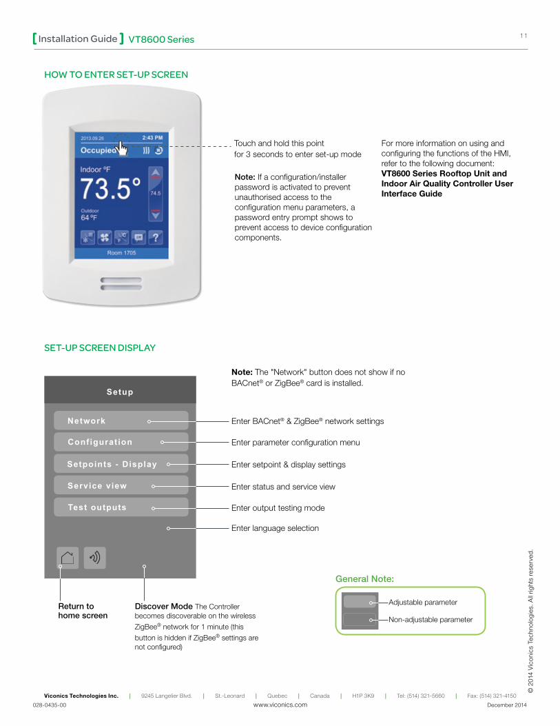
HOW TO ENTER SET-UP SCREEN
Touch and hold this point for 3 seconds to enter set-up mode
SET-UP SCREEN DISPLAY
Return to home screen
General Note:
Setup
Network
Configuration
Setpoints - Display
Service view
Test outputs
Adjustable parameter
Non-adjustable parameter
Note: If a configuration/installer password is activated to prevent unauthorised access to the configuration menu parameters, a password entry prompt shows to prevent access to device configuration components.
Discover Mode The Controller becomes discoverable on the wireless
ZigBee® network for 1 minute (this
button is hidden if ZigBee® settings are not configured)
Enter BACnet® & ZigBee® network settings
Enter parameter configuration menu
Enter setpoint & display settings
Enter output testing mode
Enter status and service view
Note: The "Network" button does not show if no BACnet® or ZigBee® card is installed.
For more information on using and configuring the functions of the HMI, refer to the following document:VT8600 Series Rooftop Unit and Indoor Air Quality Controller User Interface Guide
Enter language selection