VT520/VT525VideoTerminal ProgrammerInformationweb.mit.edu/dosathena/doc/www/ek-vt520-rm.pdf ·...
610
VT520/VT525 Video Terminal Programmer Information Order Number: EK-VT520-RM. A01
Transcript of VT520/VT525VideoTerminal ProgrammerInformationweb.mit.edu/dosathena/doc/www/ek-vt520-rm.pdf ·...

VT520/VT525 Video TerminalProgrammer Information
dt
Order Number: EK-VT520-RM. A01
July 1994
Digital Equipment Corporation makes no representations that the use of its products in themanner described in this publication will not infringe on existing or future patent rights, nor dothe descriptions contained in this publication imply the granting of licenses to make, use, or sellequipment or software in accordance with the description.
DEC, OpenVMS, VT, and the DIGITAL logo are trademarks of Digital Equipment Corporation.
ADDS is a trademark of Applied Digital Data Systems, Inc.IBM, ProPrinter, and PS/2 are registered trademarks of International Business MachinesCorporation.MS–DOS is a registered trademark and Windows is a trademark of Microsoft Corporation.SCO is a trademark of Santa Cruz Operations, Inc.TVI is a trademark of TeleVideo, Inc.UNIX is a registered trademark of UNIX System Laboratories, Inc.WY and WYSE are registered trademarks of Wyse Technologies.
All other trademarks and registered trademarks are the property of their respective holders.The Energy Star emblem does not represent EPA endoresement of any product or service.
Copyright © Digital Equipment Corporation 1994. All Rights Reserved.Printed in U.S.A.
For copies of manuals, contact your local sales office.
This document was prepared using VAX DOCUMENT Version 2.1.

Preface
IntroductionThis manual provides detailed information for advanced users, consultants, andprogrammers. This manual has the following parts, chapters, and appendices:
• Part I, VT520 Video Terminal
• Chapter 1, Overview
• Chapter 2, Set-Up
• Chapter 3, Desktop Features
• Part II, VT520 ANSI Mode
• Chapter 4, ANSI Control Functions Summary
• Chapter 5, ANSI Control Functions
• Chapter 6, SCO Console Emulation
• Chapter 7, Character Sets
• Chapter 8, Keyboard Processing
• Chapter 9, Communications
• Chapter 10, Printer Port
• Part III, VT520 ASCII Emulation
• Chapter 11, ASCII Emulations and Control Functions
• Chapter 12, ASCII Escape Sequences
• Chapter 13, Defining and Loading ASCII Character Fonts
• Appendix A, VT Keyboard Legend Data
• Appendix B, Enhanced PC Keyboards
• Appendix C, ASCII Keycodes and Local Functions
• Appendix D, VT520 Termcap Data
• Appendix E, ANSI Control Function Index
iii

ConventionsThe following conventions are used in this manual:
Set-Up features Terminal Set-Up menu selections appear in boldface type.
Alt/Ctrl/Print Screen Multiple keys are separated by a slash (/) and should bepressed in combination. That is, all three keys Alt , Ctrl , and
Print Screen are pressed down at the same time.
Characters in controlfunctions
Control function characters are in boldface type. Beloweach character is a column/row number that indicates thecharacter’s position in a standard code table. For example:
ESC # 6 (= Control function
1/11 2/3 3/6 (= Column/row numbers
Parameters Parameters appear in italic type.
Note Provides general information.
How to Use This ManualThe VT520 Video Terminal Programmer Information is written for four audiences:an advanced user, who needs to know more about the terminal Set-Up features;a programmer, who develops application programs; a software product supportperson, who provides assistance to application programmers and users; and ahardware systems engineer, who need more information on terminal connections.
Advanced UserIf you have read the VT520 Video Terminal Installation and OperatingInformation manual and need more information on the the terminal Set-Upfeatures, you may wish to refer to the following:
• Index
• Chapter 1—Overview—Provides a brief summary of the product.
• Chapter 2—Set-Up—Describes each entry in the Set-Up menus in the orderthat is displayed in the terminal.
• Chapter 3—Desktop Features—Provides a more in-depth description of thedesktop features of the terminal.
• Chapter 6—Keyboard Processing—Describes the differences in the typesof keyboard layouts supported, local functions, and accessibility aids.
ProgrammerIf you are using ANSI control functions for your program, then you may wish tostart with Part II of the manual:
• Chapter 4—ANSI Control Function Summary— Provides a tutorialsection on Control Functions and information on designing and down-lineloading a Soft Character set (soft font). In this chapter, the Control Functionsare grouped according to the task to be performed. The information on eachControl Function is very brief. If you need more information, the mnemonicat the end of the line item refers to a command section in Chapter 5.
• Chapter 5—ANSI Control Functions—Provides in-depth information oneach control function listed in alphabetic order according to the mnemonic.
• Chapter 2—Set-Up—Lists the Set-Up factory defaults at the end of thischapter, with their host control code mnemonic.
iv
• Chapter 6—Keyboard Processing—Describes the keyboard layouts,keyboard-to-host interface, keypad sequences, local functions, LEDs controls,languages, accents, scan codes, and control codes.
• Chapter 9—Communications—Describes the serial communications fromthe terminal to the host ports and the hardware and software handshaking.
• Chapter 10—Printer Port—Describes the parallel printer port and theswitching sequences for the modes supported.
• Appendix A—VT Keyboard Legend Data
• Appendix B—Enhanced PC Keyboard Legend Data
• Appendix D—VT500 Termcap Data
If you are developing a application program for a SCO Console, then you maywish to refer to:
• Chapter 6—SCO Console Emulation—Describes the SCO Console mode,including the Control Functions relative to the SCO Console applications.
If you are using ASCII control functions for your program, then you may wish tostart with Part III of the manual:
• Chapter 11—ASCII Emulations and Control Functions— Provides anoverview of the ASCII emulation, the coding notation, and the symbols usedin the ASCII sequence tables.
• Chapter 12—ASCII Escape Sequences—Summarizes the ASCII escapeand control sequences for the various ASCII emulation modes, according tothe task to be performed.
• Chapter 13—Defining and Loading ASCII Character Fonts – Providesspecific information on loading font banks and designing an ASCII characterfont.
• Appendix C—ASCII Keycodes and Local Functions
Software Product SupportIf you are helping a user or programmer with an application, then you may wishto refer to the following:
• Appendix E—ANSI Control Function Index—Lists the control functionsby their final character, which makes them easier to find in a program. Themnemonic at the end of the line item refers to a command in Chapter 5, listedin alphabetic order.
• Index—Lists control functions by mnemonic or by name and lists othersubjects by topic.
• Chapter 5—ANSI Control Functions—Provides in-depth information onspecific control functions.
• Chapter 6—Keyboard Processing—Lists the scan codes Make and Breaksequences.
• Appendix D—VT500 Termcap Data—Provides the Termcap information forANSI emulations.
v

Hardware Systems EngineerIf you are helping a user to install the terminal or to operate within a specificenvironment, then you may wish to refer to the following:
• Index—Search by topic.
• Chapter 1—Overview Provides a brief summary of the product.
• Chapter 2—Set-Up Describes each entry in the order that is displayed inthe terminal, starting with the Actions menu and lists the modes supported.Also lists the Set-Up factory defaults.
• Chapter 9—Communications—Describes the serial communications fromthe terminal to the host ports, pin numbers and signals, and the hardwareand software handshaking.
• Chapter 10—Printer Port—Describes the parallel printer port, pin numbersand signals, and modes supported.
vi

Contents
Preface . . . . . . . . . . . . . . . . . . . . . . . . . . . . . . . . . . . . . . . . . . . . . . . . . . . . . . . . . . . . iii
Part I VT520 Video Terminal
1 Overview
1.1 Introduction . . . . . . . . . . . . . . . . . . . . . . . . . . . . . . . . . . . . . . . . . . . . . . . . 1–11.2 Communications Features . . . . . . . . . . . . . . . . . . . . . . . . . . . . . . . . . . . . . 1–11.3 Keyboard Features . . . . . . . . . . . . . . . . . . . . . . . . . . . . . . . . . . . . . . . . . . . 1–21.4 Printer Port Features . . . . . . . . . . . . . . . . . . . . . . . . . . . . . . . . . . . . . . . . . 1–31.5 Display and Text Capabilities . . . . . . . . . . . . . . . . . . . . . . . . . . . . . . . . . . 1–31.5.1 ANSI . . . . . . . . . . . . . . . . . . . . . . . . . . . . . . . . . . . . . . . . . . . . . . . . . . 1–31.5.2 ASCII . . . . . . . . . . . . . . . . . . . . . . . . . . . . . . . . . . . . . . . . . . . . . . . . . . 1–31.6 Enhanced Set-Up . . . . . . . . . . . . . . . . . . . . . . . . . . . . . . . . . . . . . . . . . . . . 1–41.7 Desktop Productivity Features . . . . . . . . . . . . . . . . . . . . . . . . . . . . . . . . . . 1–41.8 Character Set Support . . . . . . . . . . . . . . . . . . . . . . . . . . . . . . . . . . . . . . . . 1–41.9 Ergonomics (Human Factors) Features . . . . . . . . . . . . . . . . . . . . . . . . . . . 1–41.10 Field-Upgradable Firmware . . . . . . . . . . . . . . . . . . . . . . . . . . . . . . . . . . . . 1–51.11 Comparison with previous VT Terminals . . . . . . . . . . . . . . . . . . . . . . . . . . 1–6
2 Set-Up
2.1 Entering Set-Up . . . . . . . . . . . . . . . . . . . . . . . . . . . . . . . . . . . . . . . . . . . . . 2–12.1.1 Effects of Entering Set-Up . . . . . . . . . . . . . . . . . . . . . . . . . . . . . . . . . . 2–22.1.2 Set-Up Languages . . . . . . . . . . . . . . . . . . . . . . . . . . . . . . . . . . . . . . . . 2–22.1.3 Power-On Settings and Defaults . . . . . . . . . . . . . . . . . . . . . . . . . . . . . 2–22.1.4 Self-test Error Messages . . . . . . . . . . . . . . . . . . . . . . . . . . . . . . . . . . . 2–32.1.5 Context Sensitivity . . . . . . . . . . . . . . . . . . . . . . . . . . . . . . . . . . . . . . . . 2–32.1.6 Set-Up Summary Line . . . . . . . . . . . . . . . . . . . . . . . . . . . . . . . . . . . . . 2–52.1.7 Set-Up Status Messages . . . . . . . . . . . . . . . . . . . . . . . . . . . . . . . . . . . . 2–52.1.8 Status Line . . . . . . . . . . . . . . . . . . . . . . . . . . . . . . . . . . . . . . . . . . . . . 2–62.1.9 Keyboard Indicator Line . . . . . . . . . . . . . . . . . . . . . . . . . . . . . . . . . . . 2–62.2 Set-Up Screen Text . . . . . . . . . . . . . . . . . . . . . . . . . . . . . . . . . . . . . . . . . . 2–72.3 Main Menu . . . . . . . . . . . . . . . . . . . . . . . . . . . . . . . . . . . . . . . . . . . . . . . . 2–82.3.1 On-Line . . . . . . . . . . . . . . . . . . . . . . . . . . . . . . . . . . . . . . . . . . . . . . . . 2–82.3.2 Save Settings . . . . . . . . . . . . . . . . . . . . . . . . . . . . . . . . . . . . . . . . . . . . 2–92.3.3 Restore Settings . . . . . . . . . . . . . . . . . . . . . . . . . . . . . . . . . . . . . . . . . . 2–92.3.4 Exit Set-Up . . . . . . . . . . . . . . . . . . . . . . . . . . . . . . . . . . . . . . . . . . . . . 2–92.4 Actions Menu . . . . . . . . . . . . . . . . . . . . . . . . . . . . . . . . . . . . . . . . . . . . . . . 2–92.4.1 Clear Display . . . . . . . . . . . . . . . . . . . . . . . . . . . . . . . . . . . . . . . . . . . . 2–92.4.2 Clear Communications . . . . . . . . . . . . . . . . . . . . . . . . . . . . . . . . . . . . . 2–92.4.3 Reset this Session . . . . . . . . . . . . . . . . . . . . . . . . . . . . . . . . . . . . . . . . 2–102.4.4 Restore Factory Defaults . . . . . . . . . . . . . . . . . . . . . . . . . . . . . . . . . . . 2–102.4.5 Clock, Calculator, Show Character Sets . . . . . . . . . . . . . . . . . . . . . . . . 2–11
vii
2.4.6 Banner Message . . . . . . . . . . . . . . . . . . . . . . . . . . . . . . . . . . . . . . . . . . 2–112.5 Multiple Sessions . . . . . . . . . . . . . . . . . . . . . . . . . . . . . . . . . . . . . . . . . . . . 2–112.5.1 Enabling and Controlling the Session Configuration . . . . . . . . . . . . . . 2–122.5.2 Multiple Sessions using a Terminal Server with TD/SMP . . . . . . . . . . 2–122.5.3 Multiple Sessions using SSU Host Software . . . . . . . . . . . . . . . . . . . . 2–122.5.4 Opening Another Session . . . . . . . . . . . . . . . . . . . . . . . . . . . . . . . . . . . 2–122.5.5 Restoring an Interrupted Session . . . . . . . . . . . . . . . . . . . . . . . . . . . . . 2–132.5.6 Session Management . . . . . . . . . . . . . . . . . . . . . . . . . . . . . . . . . . . . . . 2–132.6 Session Menu . . . . . . . . . . . . . . . . . . . . . . . . . . . . . . . . . . . . . . . . . . . . . . . 2–132.6.1 Select Session . . . . . . . . . . . . . . . . . . . . . . . . . . . . . . . . . . . . . . . . . . . . 2–142.6.2 Session Name . . . . . . . . . . . . . . . . . . . . . . . . . . . . . . . . . . . . . . . . . . . . 2–142.6.3 Pages per Session . . . . . . . . . . . . . . . . . . . . . . . . . . . . . . . . . . . . . . . . . 2–142.6.4 Soft Character Sets/Session . . . . . . . . . . . . . . . . . . . . . . . . . . . . . . . . . 2–162.6.5 Save Settings for All and Restore Settings for All . . . . . . . . . . . . . . . . 2–162.6.6 Copy Settings from Menu . . . . . . . . . . . . . . . . . . . . . . . . . . . . . . . . . . . 2–172.6.7 Update Session . . . . . . . . . . . . . . . . . . . . . . . . . . . . . . . . . . . . . . . . . . 2–172.7 Resetting and Restoring Defaults . . . . . . . . . . . . . . . . . . . . . . . . . . . . . . . . 2–182.7.1 Reset Session . . . . . . . . . . . . . . . . . . . . . . . . . . . . . . . . . . . . . . . . . . . . 2–182.7.2 Restore Factory Defaults . . . . . . . . . . . . . . . . . . . . . . . . . . . . . . . . . . . 2–182.8 Display Menu . . . . . . . . . . . . . . . . . . . . . . . . . . . . . . . . . . . . . . . . . . . . . . . 2–192.8.1 Lines per Screen . . . . . . . . . . . . . . . . . . . . . . . . . . . . . . . . . . . . . . . . . 2–202.8.1.1 Auto Resize . . . . . . . . . . . . . . . . . . . . . . . . . . . . . . . . . . . . . . . . . . 2–202.8.2 Lines per Page . . . . . . . . . . . . . . . . . . . . . . . . . . . . . . . . . . . . . . . . . . . 2–202.8.3 Review Previous Lines Buffer . . . . . . . . . . . . . . . . . . . . . . . . . . . . . . . 2–212.8.4 Columns per Page, Clear on Change . . . . . . . . . . . . . . . . . . . . . . . . . . 2–222.8.5 Status Display . . . . . . . . . . . . . . . . . . . . . . . . . . . . . . . . . . . . . . . . . . . 2–222.8.6 Scrolling Mode . . . . . . . . . . . . . . . . . . . . . . . . . . . . . . . . . . . . . . . . . . . 2–222.8.7 Screen Background . . . . . . . . . . . . . . . . . . . . . . . . . . . . . . . . . . . . . . . 2–222.8.8 Cursor Display . . . . . . . . . . . . . . . . . . . . . . . . . . . . . . . . . . . . . . . . . . . 2–222.8.9 Cursor Coupling . . . . . . . . . . . . . . . . . . . . . . . . . . . . . . . . . . . . . . . . . . 2–222.8.10 Writing Direction . . . . . . . . . . . . . . . . . . . . . . . . . . . . . . . . . . . . . . . . . 2–232.8.11 Zero . . . . . . . . . . . . . . . . . . . . . . . . . . . . . . . . . . . . . . . . . . . . . . . . . . . 2–232.8.12 Auto Wrap . . . . . . . . . . . . . . . . . . . . . . . . . . . . . . . . . . . . . . . . . . . . . . 2–232.8.13 New Line Mode . . . . . . . . . . . . . . . . . . . . . . . . . . . . . . . . . . . . . . . . . . 2–232.8.14 Lock User Preferences . . . . . . . . . . . . . . . . . . . . . . . . . . . . . . . . . . . . . 2–232.8.15 Show Control Characters . . . . . . . . . . . . . . . . . . . . . . . . . . . . . . . . . . . 2–242.8.16 CRT Saver . . . . . . . . . . . . . . . . . . . . . . . . . . . . . . . . . . . . . . . . . . . . . . 2–242.8.17 Energy Saver . . . . . . . . . . . . . . . . . . . . . . . . . . . . . . . . . . . . . . . . . . . . 2–242.8.17.1 Warning Bell . . . . . . . . . . . . . . . . . . . . . . . . . . . . . . . . . . . . . . . . . 2–252.8.18 Overscan . . . . . . . . . . . . . . . . . . . . . . . . . . . . . . . . . . . . . . . . . . . . . . . 2–252.8.19 Framed Windows . . . . . . . . . . . . . . . . . . . . . . . . . . . . . . . . . . . . . . . . . 2–252.8.20 Screen Alignment . . . . . . . . . . . . . . . . . . . . . . . . . . . . . . . . . . . . . . . . . 2–272.9 Color Set-Up . . . . . . . . . . . . . . . . . . . . . . . . . . . . . . . . . . . . . . . . . . . . . . . 2–282.9.1 Assign Colors . . . . . . . . . . . . . . . . . . . . . . . . . . . . . . . . . . . . . . . . . . . . 2–282.9.2 Alternate Text Colors . . . . . . . . . . . . . . . . . . . . . . . . . . . . . . . . . . . . . . 2–302.9.3 Define Colors Dialog Box . . . . . . . . . . . . . . . . . . . . . . . . . . . . . . . . . . . 2–312.9.4 Select Color Mode . . . . . . . . . . . . . . . . . . . . . . . . . . . . . . . . . . . . . . . . 2–322.9.5 ASCII Color Mode . . . . . . . . . . . . . . . . . . . . . . . . . . . . . . . . . . . . . . . . 2–322.9.6 Bold and Blink Style . . . . . . . . . . . . . . . . . . . . . . . . . . . . . . . . . . . . . . 2–322.9.7 Erase Color . . . . . . . . . . . . . . . . . . . . . . . . . . . . . . . . . . . . . . . . . . . . . 2–322.9.8 Reverse and Blank Attributes . . . . . . . . . . . . . . . . . . . . . . . . . . . . . . . 2–332.9.9 Intensity Attributes . . . . . . . . . . . . . . . . . . . . . . . . . . . . . . . . . . . . . . . 2–332.10 Terminal Type Menu . . . . . . . . . . . . . . . . . . . . . . . . . . . . . . . . . . . . . . . . . 2–332.10.1 Emulation Mode . . . . . . . . . . . . . . . . . . . . . . . . . . . . . . . . . . . . . . . . . . 2–33
viii
2.10.2 Terminal ID to Host . . . . . . . . . . . . . . . . . . . . . . . . . . . . . . . . . . . . . . . 2–342.10.3 VT Default Character Set . . . . . . . . . . . . . . . . . . . . . . . . . . . . . . . . . . 2–342.10.4 PCTerm Character Set . . . . . . . . . . . . . . . . . . . . . . . . . . . . . . . . . . . . . 2–342.10.5 7-Bit NRCS Characters . . . . . . . . . . . . . . . . . . . . . . . . . . . . . . . . . . . . 2–342.10.6 Transmit 7-Bit Controls . . . . . . . . . . . . . . . . . . . . . . . . . . . . . . . . . . . . 2–342.11 ASCII Emulation Menu . . . . . . . . . . . . . . . . . . . . . . . . . . . . . . . . . . . . . . . 2–352.12 Keyboard Menu . . . . . . . . . . . . . . . . . . . . . . . . . . . . . . . . . . . . . . . . . . . . . 2–362.12.1 Keyboard Language . . . . . . . . . . . . . . . . . . . . . . . . . . . . . . . . . . . . . . . 2–372.12.2 Define Key Editor . . . . . . . . . . . . . . . . . . . . . . . . . . . . . . . . . . . . . . . . 2–372.12.2.1 Copy of Key Default—Moving a Standard Function . . . . . . . . . . . . 2–382.12.2.2 Customization . . . . . . . . . . . . . . . . . . . . . . . . . . . . . . . . . . . . . . . . 2–392.12.2.3 Modifier Keys . . . . . . . . . . . . . . . . . . . . . . . . . . . . . . . . . . . . . . . . . 2–392.12.2.4 Creating a New Function . . . . . . . . . . . . . . . . . . . . . . . . . . . . . . . . 2–392.12.2.5 Examples of Creating New Functions . . . . . . . . . . . . . . . . . . . . . . 2–392.12.2.6 Correcting a Mistake . . . . . . . . . . . . . . . . . . . . . . . . . . . . . . . . . . . 2–402.12.2.7 Creating A New Alphanumeric Key or Keyboard Layout . . . . . . . . 2–402.12.2.8 Examples of Creating New Alphanumeric Keys . . . . . . . . . . . . . . . 2–402.12.2.9 User-Defined Keys . . . . . . . . . . . . . . . . . . . . . . . . . . . . . . . . . . . . . 2–412.12.2.10 Programming Notes . . . . . . . . . . . . . . . . . . . . . . . . . . . . . . . . . . . . 2–412.12.3 Save Key Definitions . . . . . . . . . . . . . . . . . . . . . . . . . . . . . . . . . . . . . . 2–422.12.4 Recall Key Definitions . . . . . . . . . . . . . . . . . . . . . . . . . . . . . . . . . . . . . 2–422.12.5 Lock Key Definitions . . . . . . . . . . . . . . . . . . . . . . . . . . . . . . . . . . . . . . 2–422.12.6 Caps Lock Function . . . . . . . . . . . . . . . . . . . . . . . . . . . . . . . . . . . . . . . 2–422.12.7 Keyclick, Warning Bell, and Margin Bell Volume . . . . . . . . . . . . . . . . . 2–422.12.7.1 Visible Bell . . . . . . . . . . . . . . . . . . . . . . . . . . . . . . . . . . . . . . . . . . . 2–432.12.8 Keyboard Encoding . . . . . . . . . . . . . . . . . . . . . . . . . . . . . . . . . . . . . . . 2–432.12.9 Auto Repeat . . . . . . . . . . . . . . . . . . . . . . . . . . . . . . . . . . . . . . . . . . . . . 2–432.12.10 Data Processing Keys . . . . . . . . . . . . . . . . . . . . . . . . . . . . . . . . . . . . . . 2–432.12.11 Application Cursor Keys . . . . . . . . . . . . . . . . . . . . . . . . . . . . . . . . . . . 2–432.12.12 Application Keypad Mode . . . . . . . . . . . . . . . . . . . . . . . . . . . . . . . . . . 2–442.12.13 Map PC Keyboard to VT . . . . . . . . . . . . . . . . . . . . . . . . . . . . . . . . . . . 2–442.12.14 Ignore Missing Keyboard . . . . . . . . . . . . . . . . . . . . . . . . . . . . . . . . . . . 2–442.13 Communication Menu . . . . . . . . . . . . . . . . . . . . . . . . . . . . . . . . . . . . . . . . 2–452.13.1 Communication Port Select . . . . . . . . . . . . . . . . . . . . . . . . . . . . . . . . . 2–462.13.2 Word Size . . . . . . . . . . . . . . . . . . . . . . . . . . . . . . . . . . . . . . . . . . . . . . . 2–472.13.3 Parity . . . . . . . . . . . . . . . . . . . . . . . . . . . . . . . . . . . . . . . . . . . . . . . . . . 2–472.13.4 Stop Bits . . . . . . . . . . . . . . . . . . . . . . . . . . . . . . . . . . . . . . . . . . . . . . . 2–472.13.5 Transmit Speed . . . . . . . . . . . . . . . . . . . . . . . . . . . . . . . . . . . . . . . . . . 2–482.13.6 Receive Speed . . . . . . . . . . . . . . . . . . . . . . . . . . . . . . . . . . . . . . . . . . . 2–482.13.7 Transmit Flow Control . . . . . . . . . . . . . . . . . . . . . . . . . . . . . . . . . . . . . 2–482.13.8 Receive Flow Control . . . . . . . . . . . . . . . . . . . . . . . . . . . . . . . . . . . . . . 2–492.13.9 Flow Control Threshold . . . . . . . . . . . . . . . . . . . . . . . . . . . . . . . . . . . . 2–492.13.10 Transmit Rate Limit, Fkey Rate Limit . . . . . . . . . . . . . . . . . . . . . . . . . 2–492.13.11 Ignore Null Character . . . . . . . . . . . . . . . . . . . . . . . . . . . . . . . . . . . . . 2–502.13.12 Local Echo . . . . . . . . . . . . . . . . . . . . . . . . . . . . . . . . . . . . . . . . . . . . . . 2–502.13.13 Half Duplex . . . . . . . . . . . . . . . . . . . . . . . . . . . . . . . . . . . . . . . . . . . . . 2–502.13.14 Auto Answerback . . . . . . . . . . . . . . . . . . . . . . . . . . . . . . . . . . . . . . . . . 2–502.13.15 Answerback Message . . . . . . . . . . . . . . . . . . . . . . . . . . . . . . . . . . . . . . 2–502.13.16 Answerback Concealed . . . . . . . . . . . . . . . . . . . . . . . . . . . . . . . . . . . . . 2–512.14 Modem Menu . . . . . . . . . . . . . . . . . . . . . . . . . . . . . . . . . . . . . . . . . . . . . . . 2–522.14.1 Enable Modem Control . . . . . . . . . . . . . . . . . . . . . . . . . . . . . . . . . . . . 2–522.14.2 Disconnect Delay . . . . . . . . . . . . . . . . . . . . . . . . . . . . . . . . . . . . . . . . . 2–522.14.3 Modem High Speed . . . . . . . . . . . . . . . . . . . . . . . . . . . . . . . . . . . . . . . 2–532.14.4 Modem Low Speed . . . . . . . . . . . . . . . . . . . . . . . . . . . . . . . . . . . . . . . . 2–53
ix
2.15 Printer Menu . . . . . . . . . . . . . . . . . . . . . . . . . . . . . . . . . . . . . . . . . . . . . . . 2–542.15.1 Port Select . . . . . . . . . . . . . . . . . . . . . . . . . . . . . . . . . . . . . . . . . . . . . . 2–542.15.2 Print Mode . . . . . . . . . . . . . . . . . . . . . . . . . . . . . . . . . . . . . . . . . . . . . . 2–542.15.3 Printer Type . . . . . . . . . . . . . . . . . . . . . . . . . . . . . . . . . . . . . . . . . . . . . 2–552.15.4 Printer Character Sets . . . . . . . . . . . . . . . . . . . . . . . . . . . . . . . . . . . . . 2–552.15.4.1 DEC/ISO Character Sets . . . . . . . . . . . . . . . . . . . . . . . . . . . . . . . . 2–562.15.4.2 PC Character Sets . . . . . . . . . . . . . . . . . . . . . . . . . . . . . . . . . . . . . 2–562.15.5 Print Extent . . . . . . . . . . . . . . . . . . . . . . . . . . . . . . . . . . . . . . . . . . . . . 2–562.15.6 Print Terminator . . . . . . . . . . . . . . . . . . . . . . . . . . . . . . . . . . . . . . . . . 2–562.15.7 Serial Print Speed . . . . . . . . . . . . . . . . . . . . . . . . . . . . . . . . . . . . . . . . 2–562.15.8 2-Way Communication . . . . . . . . . . . . . . . . . . . . . . . . . . . . . . . . . . . . . 2–572.15.9 Transmit Flow Control . . . . . . . . . . . . . . . . . . . . . . . . . . . . . . . . . . . . . 2–572.15.10 Receive Flow Control . . . . . . . . . . . . . . . . . . . . . . . . . . . . . . . . . . . . . . 2–572.15.11 Word Size . . . . . . . . . . . . . . . . . . . . . . . . . . . . . . . . . . . . . . . . . . . . . . . 2–572.15.12 Parity . . . . . . . . . . . . . . . . . . . . . . . . . . . . . . . . . . . . . . . . . . . . . . . . . . 2–582.15.13 Stop Bits . . . . . . . . . . . . . . . . . . . . . . . . . . . . . . . . . . . . . . . . . . . . . . . 2–582.15.14 Same as Receive . . . . . . . . . . . . . . . . . . . . . . . . . . . . . . . . . . . . . . . . . . 2–582.16 Tabs . . . . . . . . . . . . . . . . . . . . . . . . . . . . . . . . . . . . . . . . . . . . . . . . . . . . . 2–582.17 Sound . . . . . . . . . . . . . . . . . . . . . . . . . . . . . . . . . . . . . . . . . . . . . . . . . . . . . 2–592.18 Set-Up Factory Defaults . . . . . . . . . . . . . . . . . . . . . . . . . . . . . . . . . . . . . . . 2–61
3 Desktop Features
3.1 Introduction . . . . . . . . . . . . . . . . . . . . . . . . . . . . . . . . . . . . . . . . . . . . . . . . 3–13.2 Invoking Desktop Features . . . . . . . . . . . . . . . . . . . . . . . . . . . . . . . . . . . . 3–13.3 Calculator . . . . . . . . . . . . . . . . . . . . . . . . . . . . . . . . . . . . . . . . . . . . . . . . . 3–23.4 Clock . . . . . . . . . . . . . . . . . . . . . . . . . . . . . . . . . . . . . . . . . . . . . . . . . . . . . 3–53.5 Review Previous Lines . . . . . . . . . . . . . . . . . . . . . . . . . . . . . . . . . . . . . . . . 3–73.6 Character Set Tables . . . . . . . . . . . . . . . . . . . . . . . . . . . . . . . . . . . . . . . . . 3–73.6.1 Show Character Sets feature . . . . . . . . . . . . . . . . . . . . . . . . . . . . . . . . 3–73.6.2 Banner message . . . . . . . . . . . . . . . . . . . . . . . . . . . . . . . . . . . . . . . . . . 3–83.7 Keyboard Summary . . . . . . . . . . . . . . . . . . . . . . . . . . . . . . . . . . . . . . . . . . 3–8
Part II VT520 ANSI Mode
4 ANSI Control Functions Summary
4.1 Introduction . . . . . . . . . . . . . . . . . . . . . . . . . . . . . . . . . . . . . . . . . . . . . . . . 4–14.2 Control Characters . . . . . . . . . . . . . . . . . . . . . . . . . . . . . . . . . . . . . . . . . . . 4–14.3 Control Functions . . . . . . . . . . . . . . . . . . . . . . . . . . . . . . . . . . . . . . . . . . . 4–54.3.1 Sequence Format . . . . . . . . . . . . . . . . . . . . . . . . . . . . . . . . . . . . . . . . . 4–54.3.2 Escape Sequences . . . . . . . . . . . . . . . . . . . . . . . . . . . . . . . . . . . . . . . . 4–64.3.3 Control Sequences . . . . . . . . . . . . . . . . . . . . . . . . . . . . . . . . . . . . . . . . 4–64.3.3.1 Control Sequence Introducer . . . . . . . . . . . . . . . . . . . . . . . . . . . . . 4–64.3.3.2 Parameters . . . . . . . . . . . . . . . . . . . . . . . . . . . . . . . . . . . . . . . . . . 4–74.3.3.3 Intermediate Characters . . . . . . . . . . . . . . . . . . . . . . . . . . . . . . . . 4–84.3.3.4 Final Character . . . . . . . . . . . . . . . . . . . . . . . . . . . . . . . . . . . . . . . 4–84.3.4 Device Control Strings . . . . . . . . . . . . . . . . . . . . . . . . . . . . . . . . . . . . . 4–84.3.5 Using Control Characters in Sequences . . . . . . . . . . . . . . . . . . . . . . . . 4–94.3.6 7-Bit Code Extension Technique . . . . . . . . . . . . . . . . . . . . . . . . . . . . . . 4–94.4 Working with 7-Bit and 8-Bit Environments . . . . . . . . . . . . . . . . . . . . . . . 4–104.4.1 Conventions for Codes Received by the Terminal . . . . . . . . . . . . . . . . . 4–104.4.2 Conventions for Codes Sent by the Terminal . . . . . . . . . . . . . . . . . . . . 4–104.5 Showing Control Characters . . . . . . . . . . . . . . . . . . . . . . . . . . . . . . . . . . . 4–11
x

4.6 Terminal Management Functions . . . . . . . . . . . . . . . . . . . . . . . . . . . . . . . . 4–154.7 ANSI Control Function Tables . . . . . . . . . . . . . . . . . . . . . . . . . . . . . . . . . . 4–164.7.1 Sessions Management Control Functions . . . . . . . . . . . . . . . . . . . . . . . 4–164.7.2 Window Management Control Functions . . . . . . . . . . . . . . . . . . . . . . . 4–174.7.3 Audible Attributes Control Functions . . . . . . . . . . . . . . . . . . . . . . . . . 4–184.7.4 Color Selection Control Functions . . . . . . . . . . . . . . . . . . . . . . . . . . . . 4–184.7.5 Visual Attributes Control Functions . . . . . . . . . . . . . . . . . . . . . . . . . . 4–204.7.6 Editing Control Functions . . . . . . . . . . . . . . . . . . . . . . . . . . . . . . . . . . 4–214.7.7 Text Processing Control Functions . . . . . . . . . . . . . . . . . . . . . . . . . . . . 4–224.7.8 Graphic Character Sets Control Functions . . . . . . . . . . . . . . . . . . . . . . 4–254.7.9 Keyboard Processing Control Functions . . . . . . . . . . . . . . . . . . . . . . . 4–274.7.10 Printer Control Functions . . . . . . . . . . . . . . . . . . . . . . . . . . . . . . . . . . 4–334.7.11 Terminal Management Control Functions . . . . . . . . . . . . . . . . . . . . . . 4–344.7.12 Terminal Management—Communications Control Functions . . . . . . . 4–394.7.13 Terminal Synchronization Control Functions . . . . . . . . . . . . . . . . . . . . 4–414.7.14 Reports Control Functions . . . . . . . . . . . . . . . . . . . . . . . . . . . . . . . . . . 4–424.8 VT52 Mode Escape Sequences . . . . . . . . . . . . . . . . . . . . . . . . . . . . . . . . . . 4–45
5 ANSI Control Functions
ANSI Conformance Levels . . . . . . . . . . . . . . . . . . . . . . . . . . . . . . . . . . . . . 5–1CBT—Cursor Backward Tabulation . . . . . . . . . . . . . . . . . . . . . . . . . . . . . . 5–3CHA—Cursor Horizontal Absolute . . . . . . . . . . . . . . . . . . . . . . . . . . . . . . . 5–3CHT—Cursor Horizontal Forward Tabulation . . . . . . . . . . . . . . . . . . . . . . 5–4CNL—Cursor Next Line . . . . . . . . . . . . . . . . . . . . . . . . . . . . . . . . . . . . . . . 5–4CPL—Cursor Previous Line . . . . . . . . . . . . . . . . . . . . . . . . . . . . . . . . . . . . 5–5CPR—Cursor Position Report . . . . . . . . . . . . . . . . . . . . . . . . . . . . . . . . . . 5–5CRM—Show Control Character Mode . . . . . . . . . . . . . . . . . . . . . . . . . . . . 5–6CUB—Cursor Backward . . . . . . . . . . . . . . . . . . . . . . . . . . . . . . . . . . . . . . 5–7CUD—Cursor Down . . . . . . . . . . . . . . . . . . . . . . . . . . . . . . . . . . . . . . . . . . 5–7CUF—Cursor Forward . . . . . . . . . . . . . . . . . . . . . . . . . . . . . . . . . . . . . . . . 5–7CUP—Cursor Position . . . . . . . . . . . . . . . . . . . . . . . . . . . . . . . . . . . . . . . . 5–8CUU—Cursor Up . . . . . . . . . . . . . . . . . . . . . . . . . . . . . . . . . . . . . . . . . . . . 5–8DA1—Primary Device Attributes . . . . . . . . . . . . . . . . . . . . . . . . . . . . . . . . 5–9DA2—Secondary Device Attributes . . . . . . . . . . . . . . . . . . . . . . . . . . . . . . 5–11DA3—Tertiary Device Attributes . . . . . . . . . . . . . . . . . . . . . . . . . . . . . . . . 5–12DCH—Delete Character . . . . . . . . . . . . . . . . . . . . . . . . . . . . . . . . . . . . . . . 5–13DDD1, DDD2, DDD3 . . . . . . . . . . . . . . . . . . . . . . . . . . . . . . . . . . . . . . . . . 5–14DECAAM—Set/Reset Auto Answerback Mode . . . . . . . . . . . . . . . . . . . . . . 5–15DECAC—Assign Color . . . . . . . . . . . . . . . . . . . . . . . . . . . . . . . . . . . . . . . 5–16DECALN—Screen Alignment Pattern . . . . . . . . . . . . . . . . . . . . . . . . . . . . 5–17DECANM—ANSI Mode . . . . . . . . . . . . . . . . . . . . . . . . . . . . . . . . . . . . . . . 5–18DECANM Exit—Exiting ANSI (VT52) Mode . . . . . . . . . . . . . . . . . . . . . . . 5–19DECARM—Autorepeat Mode . . . . . . . . . . . . . . . . . . . . . . . . . . . . . . . . . . . 5–19DECARR—Select Auto Repeat Rate . . . . . . . . . . . . . . . . . . . . . . . . . . . . . 5–20DECARSM—Set/Reset Auto Resize Mode . . . . . . . . . . . . . . . . . . . . . . . . . 5–21DECATC—Alternate Text Color . . . . . . . . . . . . . . . . . . . . . . . . . . . . . . . . 5–22DECATCBM—Set/Reset Alternate Text Color Blink Mode . . . . . . . . . . . . . 5–23DECATCUM—Set/Reset Alternate Text Color Underline Mode . . . . . . . . . 5–23DECAUPSS—Assigning User-Preferred Supplemental Sets . . . . . . . . . . . 5–24
xi

DECAWM—Autowrap Mode . . . . . . . . . . . . . . . . . . . . . . . . . . . . . . . . . . . 5–25DECBBSM—Bold and Blink Style Mode . . . . . . . . . . . . . . . . . . . . . . . . . 5–25DECBI—Back Index . . . . . . . . . . . . . . . . . . . . . . . . . . . . . . . . . . . . . . . . . 5–26DECBKM—Backarrow Key Mode . . . . . . . . . . . . . . . . . . . . . . . . . . . . . . . 5–26DECCANSM—Conceal Answerback Message Mode . . . . . . . . . . . . . . . . . 5–27DECCAPSLK—Caps Lock Mode . . . . . . . . . . . . . . . . . . . . . . . . . . . . . . . . 5–28DECCARA—Change Attributes in Rectangular Area . . . . . . . . . . . . . . . . 5–28DECCIR—Cursor Information Report (Terminal to Host) . . . . . . . . . . . . . 5–30DECCKD—Copy Key Default . . . . . . . . . . . . . . . . . . . . . . . . . . . . . . . . . . . 5–31DECCKM—Cursor Keys Mode . . . . . . . . . . . . . . . . . . . . . . . . . . . . . . . . . . 5–32DECCKSR—Memory Checksum Report . . . . . . . . . . . . . . . . . . . . . . . . . . . 5–33DECCOLM—Selecting 80 or 132 Columns per Page . . . . . . . . . . . . . . . . . 5–34DECCRA—Copy Rectangular Area . . . . . . . . . . . . . . . . . . . . . . . . . . . . . . 5–35DECCRTST—CRT Saver Timing . . . . . . . . . . . . . . . . . . . . . . . . . . . . . . . 5–36DECCRTSM—Set/Reset CRT Save Mode . . . . . . . . . . . . . . . . . . . . . . . . . . 5–37DECDC—Delete Column . . . . . . . . . . . . . . . . . . . . . . . . . . . . . . . . . . . . . . 5–37DECDHL—Double-Width, Double-Height Line . . . . . . . . . . . . . . . . . . . . . 5–38DECDLD—Dynamically Redefinable Character Sets Extension . . . . . . . . . 5–39DECDMAC—Define Macro . . . . . . . . . . . . . . . . . . . . . . . . . . . . . . . . . . . . 5–45DECDLDA—Down Line Load Allocation . . . . . . . . . . . . . . . . . . . . . . . . . 5–47DECDWL—Double-Width, Single-Height Line . . . . . . . . . . . . . . . . . . . . . 5–48DECECM—Erase Color Mode . . . . . . . . . . . . . . . . . . . . . . . . . . . . . . . . . . 5–48DECEKBD—Extended Keyboard Report . . . . . . . . . . . . . . . . . . . . . . . . . 5–49DECELF—Enable Local Functions . . . . . . . . . . . . . . . . . . . . . . . . . . . . . . 5–51DECERA—Erase Rectangular Area . . . . . . . . . . . . . . . . . . . . . . . . . . . . . 5–52DECES—Enable Session . . . . . . . . . . . . . . . . . . . . . . . . . . . . . . . . . . . . . . 5–53DECESKM—Enable Secondary Keyboard Language Mode . . . . . . . . . . . . 5–53DECFI—Forward Index . . . . . . . . . . . . . . . . . . . . . . . . . . . . . . . . . . . . . . . 5–54DECFRA—Fill Rectangular Area . . . . . . . . . . . . . . . . . . . . . . . . . . . . . . . . 5–55DECFWM—Set/Reset Framed Windows Mode . . . . . . . . . . . . . . . . . . . . . . 5–56DECHDPXM—Set/Reset Half-Duplex Mode . . . . . . . . . . . . . . . . . . . . . . . 5–56DECHEM—Hebrew Encoding Mode . . . . . . . . . . . . . . . . . . . . . . . . . . . . . 5–57DECHEBM—Hebrew/N-A Keyboard Mapping Mode . . . . . . . . . . . . . . . . . 5–58DECHWUM—Host Wake-Up Mode (CRT and Energy Saver) . . . . . . . . . . 5–59DECIC—Insert Column . . . . . . . . . . . . . . . . . . . . . . . . . . . . . . . . . . . . . . . 5–59DECID—Identify Device . . . . . . . . . . . . . . . . . . . . . . . . . . . . . . . . . . . . . . 5–60DECINVM—Invoke Macro . . . . . . . . . . . . . . . . . . . . . . . . . . . . . . . . . . . . . 5–61DECIPEM—Enter/Return from IBM ProPrinter Emulation Mode . . . . . . . 5–62DECKBD—Keyboard Language Selection . . . . . . . . . . . . . . . . . . . . . . . . . 5–63DECKBUM—Typewriter or Data Processing Keys . . . . . . . . . . . . . . . . . . 5–65DECKLHIM—Keyboard LED’s Host Indicator Mode . . . . . . . . . . . . . . . . . 5–65DECKPAM—Keypad Application Modes . . . . . . . . . . . . . . . . . . . . . . . . . . 5–66DECKPM—Key Position Mode . . . . . . . . . . . . . . . . . . . . . . . . . . . . . . . . . . 5–66DECKPNM—Keypad Numeric Modes . . . . . . . . . . . . . . . . . . . . . . . . . . . . 5–67DECLANS—Load Answerback Message . . . . . . . . . . . . . . . . . . . . . . . . . . 5–68DECLBAN—Load Banner Message . . . . . . . . . . . . . . . . . . . . . . . . . . . . . . 5–69DECLFKC—Local Function Key Control . . . . . . . . . . . . . . . . . . . . . . . . . 5–70
xii

DECLL—Load LEDs . . . . . . . . . . . . . . . . . . . . . . . . . . . . . . . . . . . . . . . . . 5–71DECLRMM—Left Right Margin Mode . . . . . . . . . . . . . . . . . . . . . . . . . . . . 5–72DECLTOD—Load Time of Day . . . . . . . . . . . . . . . . . . . . . . . . . . . . . . . . . 5–72DECMCM—Modem Control Mode . . . . . . . . . . . . . . . . . . . . . . . . . . . . . . . 5–73DECMSR—Macro Space Report . . . . . . . . . . . . . . . . . . . . . . . . . . . . . . . . . 5–73DECNAKB—Greek/N-A Keyboard Mapping Mode . . . . . . . . . . . . . . . . . . . 5–74DECNCSM—No Clearing Screen On Column Change Mode . . . . . . . . . . . 5–74DECNKM—Numeric Keypad Mode . . . . . . . . . . . . . . . . . . . . . . . . . . . . . . 5–75DECNRCM—National Replacement Character Set Mode . . . . . . . . . . . . . 5–75DECNULM—Null Mode . . . . . . . . . . . . . . . . . . . . . . . . . . . . . . . . . . . . . . . 5–76DECNUMLK—Num Lock Mode . . . . . . . . . . . . . . . . . . . . . . . . . . . . . . . . . 5–76DECOM—Origin Mode . . . . . . . . . . . . . . . . . . . . . . . . . . . . . . . . . . . . . . . . 5–77DECOSCNM—Set/Reset Overscan Mode (VT520 only) . . . . . . . . . . . . . . . 5–77DECPAK—Program Alphanumeric Key . . . . . . . . . . . . . . . . . . . . . . . . . . . 5–78DECPCCM—Page Cursor-Coupling Mode . . . . . . . . . . . . . . . . . . . . . . . . . 5–80DECPCTERM—Enter/Exit PCTerm or Scancode Mode . . . . . . . . . . . . . . . 5–81DECPEX—Print Extent Mode . . . . . . . . . . . . . . . . . . . . . . . . . . . . . . . . . . 5–83DECPFF—Print Form Feed Mode . . . . . . . . . . . . . . . . . . . . . . . . . . . . . . . 5–83DECPFK—Program Function Key . . . . . . . . . . . . . . . . . . . . . . . . . . . . . . . 5–84DECPKA—Program Key Action . . . . . . . . . . . . . . . . . . . . . . . . . . . . . . . . . 5–87DECPKFMR—Program Key Free Memory Report . . . . . . . . . . . . . . . . . . 5–88DECPS—Play Sound . . . . . . . . . . . . . . . . . . . . . . . . . . . . . . . . . . . . . . . . . 5–89DECRARA—Reverse Attributes in Rectangular Area . . . . . . . . . . . . . . . . 5–90DECRC—Restore Cursor . . . . . . . . . . . . . . . . . . . . . . . . . . . . . . . . . . . . . . 5–92DECRLCM—Right-to-Left Copy Mode . . . . . . . . . . . . . . . . . . . . . . . . . . . . 5–92DECRLM—Right-to-Left Mode . . . . . . . . . . . . . . . . . . . . . . . . . . . . . . . . . 5–93DECRPAK—Report All Modifiers/Alphanumeric Key State . . . . . . . . . . . . 5–94DECRPDE—Report Displayed Extent . . . . . . . . . . . . . . . . . . . . . . . . . . . . 5–95DECRPFK - Report Function Key Definition . . . . . . . . . . . . . . . . . . . . . . . 5–96DECRPKT—Report Key Type . . . . . . . . . . . . . . . . . . . . . . . . . . . . . . . . . . 5–96DECRPL—Review Previous Lines Mode . . . . . . . . . . . . . . . . . . . . . . . . . . 5–97DECRPM—Report Mode - Terminal To Host . . . . . . . . . . . . . . . . . . . . . . . 5–98DECRPSS—Report Selection or Setting . . . . . . . . . . . . . . . . . . . . . . . . . . . 5–102DECRPTUI—Report Terminal Unit ID . . . . . . . . . . . . . . . . . . . . . . . . . . . 5–104DECRQCRA—Request Checksum of Rectangular Area . . . . . . . . . . . . . . . 5–105DECRQDE—Request Displayed Extent . . . . . . . . . . . . . . . . . . . . . . . . . . . 5–105DECRQKD—Request Key Definition . . . . . . . . . . . . . . . . . . . . . . . . . . . . . 5–106DECRQKT—Request Key Type . . . . . . . . . . . . . . . . . . . . . . . . . . . . . . . . . 5–107DECRQM—Request Mode - Host To Terminal . . . . . . . . . . . . . . . . . . . . . . 5–108DECRQPKFM—Request Program Key Free Memory . . . . . . . . . . . . . . . . 5–111DECRQPSR—Request Presentation State Report . . . . . . . . . . . . . . . . . . . 5–111DECRQSS—Request Selection or Setting . . . . . . . . . . . . . . . . . . . . . . . . . 5–112DECRQTSR—Request Terminal State Report . . . . . . . . . . . . . . . . . . . . . 5–113DECCTR—Color Table Request . . . . . . . . . . . . . . . . . . . . . . . . . . . . . . . . . 5–114DECRQUPSS—Request User-Preferred Supplemental Set . . . . . . . . . . . . 5–115DECRSPS—Restore Presentation State . . . . . . . . . . . . . . . . . . . . . . . . . . 5–116DECRSTS—Restore Terminal State . . . . . . . . . . . . . . . . . . . . . . . . . . . . . 5–117
xiii

DECRSTS—Restore Terminal Color Table State . . . . . . . . . . . . . . . . . . . . 5–118DECSACE—Select Attribute Change Extent . . . . . . . . . . . . . . . . . . . . . . 5–119DECSASD—Select Active Status Display . . . . . . . . . . . . . . . . . . . . . . . . . 5–120DECSC—Save Cursor . . . . . . . . . . . . . . . . . . . . . . . . . . . . . . . . . . . . . . . . 5–120DECSCA—Select Character Protection Attribute . . . . . . . . . . . . . . . . . . . 5–121DECSCL—Select Conformance Level . . . . . . . . . . . . . . . . . . . . . . . . . . . . . 5–122DECSCLM—Scrolling Mode . . . . . . . . . . . . . . . . . . . . . . . . . . . . . . . . . . . 5–123DECSCNM—Screen Mode: Light or Dark Screen . . . . . . . . . . . . . . . . . . . 5–123DECSCP—Select Communication Port . . . . . . . . . . . . . . . . . . . . . . . . . . . 5–124DECSCPP—Select Columns Per Page . . . . . . . . . . . . . . . . . . . . . . . . . . . 5–125DECSCS—Select Communication Speed . . . . . . . . . . . . . . . . . . . . . . . . . . 5–126DECSCUSR—Set Cursor Style . . . . . . . . . . . . . . . . . . . . . . . . . . . . . . . . . 5–127DECSDDT—Select Disconnect Delay Time . . . . . . . . . . . . . . . . . . . . . . . . 5–128DECSDPT—Select Digital Printed Data Type . . . . . . . . . . . . . . . . . . . . . . 5–129DECSED—Selective Erase in Display . . . . . . . . . . . . . . . . . . . . . . . . . . . . 5–129DECSEST—Energy Saver Timing . . . . . . . . . . . . . . . . . . . . . . . . . . . . . . . 5–130DECSEL—Selective Erase in Line . . . . . . . . . . . . . . . . . . . . . . . . . . . . . . . 5–131DECSERA—Selective Erase Rectangular Area . . . . . . . . . . . . . . . . . . . . . 5–132DECSFC—Select Flow Control . . . . . . . . . . . . . . . . . . . . . . . . . . . . . . . . . 5–133DECSIN—Set Icon Name . . . . . . . . . . . . . . . . . . . . . . . . . . . . . . . . . . . . . 5–134DECSKCV—Set Key Click Volume . . . . . . . . . . . . . . . . . . . . . . . . . . . . . . 5–135DECSLCK—Set Lock Key Style . . . . . . . . . . . . . . . . . . . . . . . . . . . . . . . . . 5–135DECSLPP—Set Lines Per Page . . . . . . . . . . . . . . . . . . . . . . . . . . . . . . . . 5–136DECSLRM—Set Left and Right Margins . . . . . . . . . . . . . . . . . . . . . . . . . 5–137DECSMBV—Set Margin Bell Volume . . . . . . . . . . . . . . . . . . . . . . . . . . . . 5–138DECSMKR—Select Modifier Key Reporting . . . . . . . . . . . . . . . . . . . . . . . 5–139DECSNLS—Set Number of Lines Per Screen . . . . . . . . . . . . . . . . . . . . . . 5–140DECSPMA—Session Page Memory Allocation . . . . . . . . . . . . . . . . . . . . . 5–141DECSPP—Set Port Parameters . . . . . . . . . . . . . . . . . . . . . . . . . . . . . . . . . 5–142DECSPPCS—Select ProPrinter Character Set . . . . . . . . . . . . . . . . . . . . . 5–143DECSPRTT—Select Printer Type . . . . . . . . . . . . . . . . . . . . . . . . . . . . . . . 5–144DECSR—Secure Reset . . . . . . . . . . . . . . . . . . . . . . . . . . . . . . . . . . . . . . . . 5–144DECSRC—Secure Reset Confirmation . . . . . . . . . . . . . . . . . . . . . . . . . . . . 5–146DECSSCLS—Set Scroll Speed . . . . . . . . . . . . . . . . . . . . . . . . . . . . . . . . . 5–146DECSSDT—Select Status Display (Line) Type . . . . . . . . . . . . . . . . . . . . . 5–147DECSSL—Select Set-Up Language . . . . . . . . . . . . . . . . . . . . . . . . . . . . . . 5–148DECST8C—Set Tab at Every 8 Columns . . . . . . . . . . . . . . . . . . . . . . . . . 5–149DECSTBM—Set Top and Bottom Margins . . . . . . . . . . . . . . . . . . . . . . . . 5–149DECSTR—Soft Terminal Reset . . . . . . . . . . . . . . . . . . . . . . . . . . . . . . . . . 5–150DECSTGLT—Select Color Look-Up Table . . . . . . . . . . . . . . . . . . . . . . . . . 5–151DECSTRL—Set Transmit Rate Limit . . . . . . . . . . . . . . . . . . . . . . . . . . . . 5–152DECSTUI—Setting Terminal Unit ID . . . . . . . . . . . . . . . . . . . . . . . . . . . . 5–153DECSWBV—Set Warning Bell Volume . . . . . . . . . . . . . . . . . . . . . . . . . . . 5–154DECSWL—Single-Width, Single-Height Line . . . . . . . . . . . . . . . . . . . . . . 5–154DECSZS—Select Zero Symbol . . . . . . . . . . . . . . . . . . . . . . . . . . . . . . . . . . 5–155DECSWT—Set Window Title . . . . . . . . . . . . . . . . . . . . . . . . . . . . . . . . . . 5–156DECTABSR—Tab Stop Report . . . . . . . . . . . . . . . . . . . . . . . . . . . . . . . . . 5–157
xiv

DECTCEM—Text Cursor Enable Mode . . . . . . . . . . . . . . . . . . . . . . . . . . . 5–157DECTID—Select Terminal ID . . . . . . . . . . . . . . . . . . . . . . . . . . . . . . . . . . 5–158DECTME—Terminal Mode Emulation . . . . . . . . . . . . . . . . . . . . . . . . . . . . 5–159DECTSR—Terminal State Report—Terminal to Host . . . . . . . . . . . . . . . . 5–160DECTSR—Terminal State Report (Color Table Report) . . . . . . . . . . . . . . . 5–161DECTST—Invoke Confidence Test . . . . . . . . . . . . . . . . . . . . . . . . . . . . . . . 5–162DECUDK—User Defined Keys . . . . . . . . . . . . . . . . . . . . . . . . . . . . . . . . . . 5–163DECUS—Update Session . . . . . . . . . . . . . . . . . . . . . . . . . . . . . . . . . . . . . . 5–169DECVCCM—Vertical Cursor-Coupling Mode . . . . . . . . . . . . . . . . . . . . . . . 5–170DECXCPR—Extended Cursor Position Report . . . . . . . . . . . . . . . . . . . . . . 5–170DECXRLM—Transmit Rate Limiting . . . . . . . . . . . . . . . . . . . . . . . . . . . . 5–171DL—Delete Line . . . . . . . . . . . . . . . . . . . . . . . . . . . . . . . . . . . . . . . . . . . . 5–172DSR—Device Status Reports . . . . . . . . . . . . . . . . . . . . . . . . . . . . . . . . . . 5–173DSR—Cursor Position Report (CPR) . . . . . . . . . . . . . . . . . . . . . . . . . . . . . 5–173DSR—Data Integrity Report . . . . . . . . . . . . . . . . . . . . . . . . . . . . . . . . . . . 5–174DSR—Extended Cursor Position Report (DECXCPR response) . . . . . . . . . 5–174DSR—Keyboard Report . . . . . . . . . . . . . . . . . . . . . . . . . . . . . . . . . . . . . . . 5–175DSR—Macro Space Report . . . . . . . . . . . . . . . . . . . . . . . . . . . . . . . . . . . . . 5–176DSR—Memory Checksum Report (DECCKSR) . . . . . . . . . . . . . . . . . . . . . 5–177DSR—Operating Status Report . . . . . . . . . . . . . . . . . . . . . . . . . . . . . . . . 5–177DSR—Printer Port Report . . . . . . . . . . . . . . . . . . . . . . . . . . . . . . . . . . . . 5–178DSR—User-Defined Keys Report (VT Level 4 or higher) . . . . . . . . . . . . . . 5–179ECH—Erase Character . . . . . . . . . . . . . . . . . . . . . . . . . . . . . . . . . . . . . . . 5–179ED—Erase in Display . . . . . . . . . . . . . . . . . . . . . . . . . . . . . . . . . . . . . . . . 5–180EL—Erase in Line . . . . . . . . . . . . . . . . . . . . . . . . . . . . . . . . . . . . . . . . . . . 5–180HPA—Horizontal Position Absolute . . . . . . . . . . . . . . . . . . . . . . . . . . . . . . 5–181HPR—Horizontal Position Relative . . . . . . . . . . . . . . . . . . . . . . . . . . . . . . 5–181HT—Horizontal Tab . . . . . . . . . . . . . . . . . . . . . . . . . . . . . . . . . . . . . . . . . . 5–182HTS—Horizontal Tab Set . . . . . . . . . . . . . . . . . . . . . . . . . . . . . . . . . . . . . . 5–182HVP—Horizontal and Vertical Position . . . . . . . . . . . . . . . . . . . . . . . . . . . 5–183ICH—Insert Character . . . . . . . . . . . . . . . . . . . . . . . . . . . . . . . . . . . . . . . . 5–183IL—Insert Line . . . . . . . . . . . . . . . . . . . . . . . . . . . . . . . . . . . . . . . . . . . . . 5–184IND—Index . . . . . . . . . . . . . . . . . . . . . . . . . . . . . . . . . . . . . . . . . . . . . . . . 5–184IRM—Insert/Replace Mode . . . . . . . . . . . . . . . . . . . . . . . . . . . . . . . . . . . . 5–185KAM—Keyboard Action Mode . . . . . . . . . . . . . . . . . . . . . . . . . . . . . . . . . . 5–185LNM—Line Feed/New Line Mode . . . . . . . . . . . . . . . . . . . . . . . . . . . . . . . 5–186LS—Locking Shift . . . . . . . . . . . . . . . . . . . . . . . . . . . . . . . . . . . . . . . . . . . 5–187MC—Media Copy . . . . . . . . . . . . . . . . . . . . . . . . . . . . . . . . . . . . . . . . . . . 5–188NEL—Next Line . . . . . . . . . . . . . . . . . . . . . . . . . . . . . . . . . . . . . . . . . . . . 5–191NP—Next Page . . . . . . . . . . . . . . . . . . . . . . . . . . . . . . . . . . . . . . . . . . . . . 5–191PP—Preceding Page . . . . . . . . . . . . . . . . . . . . . . . . . . . . . . . . . . . . . . . . . . 5–192PPA—Page Position Absolute . . . . . . . . . . . . . . . . . . . . . . . . . . . . . . . . . . 5–192PPB—Page Position Backward . . . . . . . . . . . . . . . . . . . . . . . . . . . . . . . . . 5–193PPR—Page Position Relative . . . . . . . . . . . . . . . . . . . . . . . . . . . . . . . . . . 5–193RIS—Reset to Initial State . . . . . . . . . . . . . . . . . . . . . . . . . . . . . . . . . . . . 5–194RM—Reset Mode . . . . . . . . . . . . . . . . . . . . . . . . . . . . . . . . . . . . . . . . . . . . 5–195S7C1T—Send C1 Control Character to the Host . . . . . . . . . . . . . . . . . . . . 5–196
xv

S8C1T—Send C1 Control Character to the Host . . . . . . . . . . . . . . . . . . . . 5–196SCS—Select Character Set . . . . . . . . . . . . . . . . . . . . . . . . . . . . . . . . . . . . 5–197Designating Character Sets (SCS Sequences) . . . . . . . . . . . . . . . . . . . . . . 5–197SD—Pan Up . . . . . . . . . . . . . . . . . . . . . . . . . . . . . . . . . . . . . . . . . . . . . . . . 5–200SGR—Select Graphic Rendition . . . . . . . . . . . . . . . . . . . . . . . . . . . . . . . . . 5–201SRM—Local Echo: Send/Receive Mode . . . . . . . . . . . . . . . . . . . . . . . . . . . 5–204SS—Single Shifts . . . . . . . . . . . . . . . . . . . . . . . . . . . . . . . . . . . . . . . . . . . . 5–205SM—Set Mode . . . . . . . . . . . . . . . . . . . . . . . . . . . . . . . . . . . . . . . . . . . . . . 5–206SU—Pan Down . . . . . . . . . . . . . . . . . . . . . . . . . . . . . . . . . . . . . . . . . . . . . 5–207TBC—Tab Clear . . . . . . . . . . . . . . . . . . . . . . . . . . . . . . . . . . . . . . . . . . . . . 5–207VPA—Vertical Line Position Absolute . . . . . . . . . . . . . . . . . . . . . . . . . . . . 5–208VPR—Vertical Position Relative . . . . . . . . . . . . . . . . . . . . . . . . . . . . . . . . . 5–208
6 SCO Console Emulation
6.1 SCO Console Emulation Mode . . . . . . . . . . . . . . . . . . . . . . . . . . . . . . . . . . 6–16.1.1 Keyboard . . . . . . . . . . . . . . . . . . . . . . . . . . . . . . . . . . . . . . . . . . . . . . . 6–26.1.1.1 Local Function Keys in SCO Console Mode . . . . . . . . . . . . . . . . . . 6–26.1.1.2 PC Keyboard . . . . . . . . . . . . . . . . . . . . . . . . . . . . . . . . . . . . . . . . . 6–26.1.1.3 VT Keyboard Key Mapping . . . . . . . . . . . . . . . . . . . . . . . . . . . . . . 6–66.2 VT520 SCO Console Control Sequences . . . . . . . . . . . . . . . . . . . . . . . . . . . 6–7
SCODFK—Define Function Key . . . . . . . . . . . . . . . . . . . . . . . . . . . . . . . . 6–7SCODPCC—Display PC Characters . . . . . . . . . . . . . . . . . . . . . . . . . . . . . . 6–8SCORC—Restore Saved Cursor Position . . . . . . . . . . . . . . . . . . . . . . . . . . 6–9SCOSC—Save Current Cursor Position . . . . . . . . . . . . . . . . . . . . . . . . . . 6–9
7 Character Sets
7.1 Overview . . . . . . . . . . . . . . . . . . . . . . . . . . . . . . . . . . . . . . . . . . . . . . . . . . 7–17.2 Character Sets Supported . . . . . . . . . . . . . . . . . . . . . . . . . . . . . . . . . . . . . 7–17.2.1 VT Graphic Character Sets . . . . . . . . . . . . . . . . . . . . . . . . . . . . . . . . . 7–17.2.2 PCTerm Graphic Character Sets . . . . . . . . . . . . . . . . . . . . . . . . . . . . . 7–27.2.3 Control Character Sets . . . . . . . . . . . . . . . . . . . . . . . . . . . . . . . . . . . . . 7–37.2.4 Character Set Structure . . . . . . . . . . . . . . . . . . . . . . . . . . . . . . . . . . . . 7–37.2.5 Characters Not in a Character Set. . . . . . . . . . . . . . . . . . . . . . . . . . . . 7–37.3 VT Mode . . . . . . . . . . . . . . . . . . . . . . . . . . . . . . . . . . . . . . . . . . . . . . . . . . 7–47.3.1 Selecting Character Sets . . . . . . . . . . . . . . . . . . . . . . . . . . . . . . . . . . . 7–47.3.2 Character Set Mappings . . . . . . . . . . . . . . . . . . . . . . . . . . . . . . . . . . . 7–47.4 PCTerm Mode . . . . . . . . . . . . . . . . . . . . . . . . . . . . . . . . . . . . . . . . . . . . . . 7–47.4.1 Selecting Character Sets . . . . . . . . . . . . . . . . . . . . . . . . . . . . . . . . . . . 7–47.4.2 Character Set Mappings . . . . . . . . . . . . . . . . . . . . . . . . . . . . . . . . . . . 7–57.5 SCO Console Mode . . . . . . . . . . . . . . . . . . . . . . . . . . . . . . . . . . . . . . . . . . . 7–57.6 Soft Character Sets . . . . . . . . . . . . . . . . . . . . . . . . . . . . . . . . . . . . . . . . . . 7–57.6.1 Designing a Soft Character Set . . . . . . . . . . . . . . . . . . . . . . . . . . . . . . 7–67.6.2 Coding the Soft Character Set . . . . . . . . . . . . . . . . . . . . . . . . . . . . . . . 7–97.6.3 Downloading Soft Characters . . . . . . . . . . . . . . . . . . . . . . . . . . . . . . . . 7–137.6.4 Designating the Soft Character Set . . . . . . . . . . . . . . . . . . . . . . . . . . . 7–147.6.5 Soft Character Set Example . . . . . . . . . . . . . . . . . . . . . . . . . . . . . . . . . 7–157.6.6 Clearing a Soft Character Set . . . . . . . . . . . . . . . . . . . . . . . . . . . . . . . 7–16
xvi

8 Keyboard Processing
8.1 Overview—Keyboard Layout . . . . . . . . . . . . . . . . . . . . . . . . . . . . . . . . . . . 8–18.2 DEC VT Layout . . . . . . . . . . . . . . . . . . . . . . . . . . . . . . . . . . . . . . . . . . . . . 8–28.3 VT Layout - PC Term Mode . . . . . . . . . . . . . . . . . . . . . . . . . . . . . . . . . . . . 8–28.4 Enhanced PC Layout - PCTerm Mode . . . . . . . . . . . . . . . . . . . . . . . . . . . . 8–38.5 Enhanced PC Layout - VT Mode . . . . . . . . . . . . . . . . . . . . . . . . . . . . . . . . 8–38.5.1 DEC VT Style . . . . . . . . . . . . . . . . . . . . . . . . . . . . . . . . . . . . . . . . . . . 8–38.5.2 IBM PC Style . . . . . . . . . . . . . . . . . . . . . . . . . . . . . . . . . . . . . . . . . . . . 8–48.6 Main Key Array . . . . . . . . . . . . . . . . . . . . . . . . . . . . . . . . . . . . . . . . . . . . . 8–48.6.1 Character Sets . . . . . . . . . . . . . . . . . . . . . . . . . . . . . . . . . . . . . . . . . . . 8–48.6.2 Tab Key . . . . . . . . . . . . . . . . . . . . . . . . . . . . . . . . . . . . . . . . . . . . . . . . 8–48.6.3 Modifier Keys . . . . . . . . . . . . . . . . . . . . . . . . . . . . . . . . . . . . . . . . . . . . 8–48.6.4 Caps Lock . . . . . . . . . . . . . . . . . . . . . . . . . . . . . . . . . . . . . . . . . . . . . . 8–58.6.5 Left Alt . . . . . . . . . . . . . . . . . . . . . . . . . . . . . . . . . . . . . . . . . . . . . . . . 8–58.6.6 Right Alt . . . . . . . . . . . . . . . . . . . . . . . . . . . . . . . . . . . . . . . . . . . . . . . 8–68.6.7 Alt Gr . . . . . . . . . . . . . . . . . . . . . . . . . . . . . . . . . . . . . . . . . . . . . . . . . . 8–68.7 Top Row Function Keys . . . . . . . . . . . . . . . . . . . . . . . . . . . . . . . . . . . . . . . 8–68.8 Editing Keypad Keys . . . . . . . . . . . . . . . . . . . . . . . . . . . . . . . . . . . . . . . . . 8–68.9 Cursor Keypad Keys . . . . . . . . . . . . . . . . . . . . . . . . . . . . . . . . . . . . . . . . . 8–78.10 Numeric Keypad Keys . . . . . . . . . . . . . . . . . . . . . . . . . . . . . . . . . . . . . . . . 8–78.11 Local Function Key Defaults . . . . . . . . . . . . . . . . . . . . . . . . . . . . . . . . . . . 8–98.11.1 Numeric Keypad Compose . . . . . . . . . . . . . . . . . . . . . . . . . . . . . . . . . . 8–148.11.2 Accessibility Aids . . . . . . . . . . . . . . . . . . . . . . . . . . . . . . . . . . . . . . . . 8–158.12 Controlling Keyboard LEDs . . . . . . . . . . . . . . . . . . . . . . . . . . . . . . . . . . . . 8–168.13 Keyboard Languages . . . . . . . . . . . . . . . . . . . . . . . . . . . . . . . . . . . . . . . . . 8–178.14 Switching Between Keyboard Languages . . . . . . . . . . . . . . . . . . . . . . . . . . 8–188.14.1 Keystroke Processing . . . . . . . . . . . . . . . . . . . . . . . . . . . . . . . . . . . . . . 8–208.14.2 Non-Spacing Accent Marks . . . . . . . . . . . . . . . . . . . . . . . . . . . . . . . . . 8–208.14.3 German . . . . . . . . . . . . . . . . . . . . . . . . . . . . . . . . . . . . . . . . . . . . . . . . 8–218.14.4 Hebrew . . . . . . . . . . . . . . . . . . . . . . . . . . . . . . . . . . . . . . . . . . . . . . . . 8–218.15 Keystation Numbers . . . . . . . . . . . . . . . . . . . . . . . . . . . . . . . . . . . . . . . . . 8–218.16 Scan Codes Sent in PCTerm Mode for EPC Keyboards . . . . . . . . . . . . . . . 8–238.17 Scan Codes Sent in PCTerm Mode for VT Keyboards . . . . . . . . . . . . . . . . 8–278.18 Control Codes and Keystrokes . . . . . . . . . . . . . . . . . . . . . . . . . . . . . . . . . . 8–28
9 Communications
9.1 Introduction to Communications . . . . . . . . . . . . . . . . . . . . . . . . . . . . . . . . 9–19.2 Physical Link Layer . . . . . . . . . . . . . . . . . . . . . . . . . . . . . . . . . . . . . . . . . . 9–29.2.1 25-Pin Connectors . . . . . . . . . . . . . . . . . . . . . . . . . . . . . . . . . . . . . . . . 9–29.2.2 DEC Corporate Modular Jacks (MMJ) . . . . . . . . . . . . . . . . . . . . . . . . . 9–39.2.3 Connector Pins Description . . . . . . . . . . . . . . . . . . . . . . . . . . . . . . . . . 9–39.2.3.1 Transmitted Data–TXD L . . . . . . . . . . . . . . . . . . . . . . . . . . . . . . . 9–49.2.3.2 Received Data–RXD L . . . . . . . . . . . . . . . . . . . . . . . . . . . . . . . . . . 9–49.2.3.3 Request to Send–RTS . . . . . . . . . . . . . . . . . . . . . . . . . . . . . . . . . . . 9–49.2.3.4 Clear to Send–CTS . . . . . . . . . . . . . . . . . . . . . . . . . . . . . . . . . . . . . 9–49.2.3.5 Data Terminal Ready–DTR . . . . . . . . . . . . . . . . . . . . . . . . . . . . . . 9–59.2.3.6 Data Set Ready–DSR . . . . . . . . . . . . . . . . . . . . . . . . . . . . . . . . . . . 9–59.2.3.6.1 Modem Initiated Disconnect . . . . . . . . . . . . . . . . . . . . . . . . . . . 9–59.2.3.6.2 Terminal Initiated Disconnect . . . . . . . . . . . . . . . . . . . . . . . . . 9–59.2.3.6.3 Modem off line . . . . . . . . . . . . . . . . . . . . . . . . . . . . . . . . . . . . . 9–69.2.3.7 Receive Line Signal Detector–RLSD . . . . . . . . . . . . . . . . . . . . . . . 9–69.2.3.8 Speed Indicator–SPDI . . . . . . . . . . . . . . . . . . . . . . . . . . . . . . . . . . 9–69.2.3.9 Speed Select–SPDS . . . . . . . . . . . . . . . . . . . . . . . . . . . . . . . . . . . . 9–7
xvii
9.2.4 Half-Duplex Mode . . . . . . . . . . . . . . . . . . . . . . . . . . . . . . . . . . . . . . . . 9–79.2.5 Supported Modem Configurations . . . . . . . . . . . . . . . . . . . . . . . . . . . . 9–79.2.5.1 CCITT Public Switched Telephone Network (2-wire only) . . . . . . . 9–79.2.5.2 CCITT Dedicated Line (2-Wire / 4-Wire) Data Network . . . . . . . . . 9–79.2.5.3 European Public Circuit Switched Data Network . . . . . . . . . . . . . 9–89.2.5.4 European Public Packet Switched Data Network (PSDN) . . . . . . . 9–89.3 Data Link Layer . . . . . . . . . . . . . . . . . . . . . . . . . . . . . . . . . . . . . . . . . . . . 9–99.3.1 7- /8-Bit VT100/VT520 Operation . . . . . . . . . . . . . . . . . . . . . . . . . . . . . 9–99.3.2 Flow Control . . . . . . . . . . . . . . . . . . . . . . . . . . . . . . . . . . . . . . . . . . . . 9–109.3.2.1 Receive Buffer . . . . . . . . . . . . . . . . . . . . . . . . . . . . . . . . . . . . . . . . 9–109.3.2.2 Flow Control Selection . . . . . . . . . . . . . . . . . . . . . . . . . . . . . . . . . . 9–109.3.2.2.1 No Flow Control . . . . . . . . . . . . . . . . . . . . . . . . . . . . . . . . . . . . 9–119.3.2.2.2 XOFF/XON or XPC Flow Control . . . . . . . . . . . . . . . . . . . . . . . 9–119.3.2.2.3 DSR/DTR Flow Control . . . . . . . . . . . . . . . . . . . . . . . . . . . . . . 9–129.3.2.2.4 Software and Hardware Combined Flow Control . . . . . . . . . . . 9–129.3.2.2.5 Flow Control Threshold . . . . . . . . . . . . . . . . . . . . . . . . . . . . . . 9–129.3.2.3 Show Control Character Mode . . . . . . . . . . . . . . . . . . . . . . . . . . . . 9–139.3.2.4 Set-Up on Flow Control Handling . . . . . . . . . . . . . . . . . . . . . . . . . 9–139.3.2.5 When Disconnect Occurs . . . . . . . . . . . . . . . . . . . . . . . . . . . . . . . . 9–139.4 Features that Affect Communications . . . . . . . . . . . . . . . . . . . . . . . . . . . . 9–139.4.1 Clear Communications . . . . . . . . . . . . . . . . . . . . . . . . . . . . . . . . . . . . . 9–149.4.2 Connection . . . . . . . . . . . . . . . . . . . . . . . . . . . . . . . . . . . . . . . . . . . . . . 9–149.4.3 Line Disconnection . . . . . . . . . . . . . . . . . . . . . . . . . . . . . . . . . . . . . . . . 9–149.4.4 Break . . . . . . . . . . . . . . . . . . . . . . . . . . . . . . . . . . . . . . . . . . . . . . . . . . 9–159.4.4.1 Received Break . . . . . . . . . . . . . . . . . . . . . . . . . . . . . . . . . . . . . . . 9–15
10 Printer Port
10.1 Overview . . . . . . . . . . . . . . . . . . . . . . . . . . . . . . . . . . . . . . . . . . . . . . . . . . 10–110.2 Serial Port . . . . . . . . . . . . . . . . . . . . . . . . . . . . . . . . . . . . . . . . . . . . . . . . . 10–110.2.1 Serial Port Flow Control . . . . . . . . . . . . . . . . . . . . . . . . . . . . . . . . . . . 10–110.3 Parallel Port . . . . . . . . . . . . . . . . . . . . . . . . . . . . . . . . . . . . . . . . . . . . . . . 10–210.3.1 Parallel Port Flow Control . . . . . . . . . . . . . . . . . . . . . . . . . . . . . . . . . . 10–310.4 Print Modes . . . . . . . . . . . . . . . . . . . . . . . . . . . . . . . . . . . . . . . . . . . . . . . . 10–310.4.1 Printer Controller Mode . . . . . . . . . . . . . . . . . . . . . . . . . . . . . . . . . . . . 10–410.5 Print Operation . . . . . . . . . . . . . . . . . . . . . . . . . . . . . . . . . . . . . . . . . . . . . 10–410.6 Transmitting Print Data . . . . . . . . . . . . . . . . . . . . . . . . . . . . . . . . . . . . . . 10–410.6.1 DEC ANSI . . . . . . . . . . . . . . . . . . . . . . . . . . . . . . . . . . . . . . . . . . . . . . 10–410.6.2 IBM ProPrinter or Compatible Printer . . . . . . . . . . . . . . . . . . . . . . . . 10–510.6.2.1 Data Transmission . . . . . . . . . . . . . . . . . . . . . . . . . . . . . . . . . . . . . 10–510.6.3 DEC ANSI with IBM ProPrinter Emulation . . . . . . . . . . . . . . . . . . . . 10–610.6.3.1 Data Transmission . . . . . . . . . . . . . . . . . . . . . . . . . . . . . . . . . . . . . 10–710.7 Printer Status . . . . . . . . . . . . . . . . . . . . . . . . . . . . . . . . . . . . . . . . . . . . . . 10–710.8 Suspending Print Operations . . . . . . . . . . . . . . . . . . . . . . . . . . . . . . . . . . . 10–710.9 Aborting Print Operations . . . . . . . . . . . . . . . . . . . . . . . . . . . . . . . . . . . . . 10–7
Part III VT520 ASCII Emulation
xviii
11 ASCII Emulations and Control Functions
11.1 Overview . . . . . . . . . . . . . . . . . . . . . . . . . . . . . . . . . . . . . . . . . . . . . . . . . . 11–111.2 ASCII Emulations . . . . . . . . . . . . . . . . . . . . . . . . . . . . . . . . . . . . . . . . . . . 11–111.2.1 Enhanced Mode . . . . . . . . . . . . . . . . . . . . . . . . . . . . . . . . . . . . . . . . . . 11–211.3 Coding Notation . . . . . . . . . . . . . . . . . . . . . . . . . . . . . . . . . . . . . . . . . . . . . 11–211.3.1 Communication Flow Control with PCTerm Mode . . . . . . . . . . . . . . . . 11–311.3.2 Protecting Data . . . . . . . . . . . . . . . . . . . . . . . . . . . . . . . . . . . . . . . . . . 11–3
12 ASCII Escape Sequences
12.1 ASCII Communications . . . . . . . . . . . . . . . . . . . . . . . . . . . . . . . . . . . . . . . 12–112.2 Terminal Management . . . . . . . . . . . . . . . . . . . . . . . . . . . . . . . . . . . . . . . . 12–412.3 Keyboard Processing . . . . . . . . . . . . . . . . . . . . . . . . . . . . . . . . . . . . . . . . . 12–512.4 Screen Processing . . . . . . . . . . . . . . . . . . . . . . . . . . . . . . . . . . . . . . . . . . . 12–1012.4.1 Rectangular Area Operations . . . . . . . . . . . . . . . . . . . . . . . . . . . . . . . . 12–2812.4.1.1 Draw Rectangle . . . . . . . . . . . . . . . . . . . . . . . . . . . . . . . . . . . . . . . 12–3112.4.1.2 Swap/Copy/Move . . . . . . . . . . . . . . . . . . . . . . . . . . . . . . . . . . . . . . 12–3112.5 Printing/Sending Data . . . . . . . . . . . . . . . . . . . . . . . . . . . . . . . . . . . . . . . . 12–3212.5.1 Sending Data . . . . . . . . . . . . . . . . . . . . . . . . . . . . . . . . . . . . . . . . . . . . 12–3212.5.2 Graphics Characters . . . . . . . . . . . . . . . . . . . . . . . . . . . . . . . . . . . . . . 12–36
13 Defining and Loading ASCII Character Fonts
13.1 Character Sets . . . . . . . . . . . . . . . . . . . . . . . . . . . . . . . . . . . . . . . . . . . . . . 13–113.1.1 PCTerm on US Keyboard . . . . . . . . . . . . . . . . . . . . . . . . . . . . . . . . . . . 13–113.1.2 WYSE and ADDS Enhanced Personalities . . . . . . . . . . . . . . . . . . . . . . 13–113.2 Loading, Defining, and Selecting Character Sets . . . . . . . . . . . . . . . . . . . . 13–313.3 Designing a Character Font . . . . . . . . . . . . . . . . . . . . . . . . . . . . . . . . . . . 13–5
A VT Keyboard Legend Data
A.1 Compose Processing and Non-spacing Diacritical Marks . . . . . . . . . . . . . . A–1A.2 VT Keyboards . . . . . . . . . . . . . . . . . . . . . . . . . . . . . . . . . . . . . . . . . . . . . . A–1
B Enhanced PC Keyboards
B.1 Summary of Non-Spacing Diacritical Marks . . . . . . . . . . . . . . . . . . . . . . . B–1B.2 Enhanced PC Keyboards . . . . . . . . . . . . . . . . . . . . . . . . . . . . . . . . . . . . . . B–2
C ASCII Keycodes and Local Functions
C.1 PC Keyboard . . . . . . . . . . . . . . . . . . . . . . . . . . . . . . . . . . . . . . . . . . . . . . . C–1C.2 DEC VT Keyboard . . . . . . . . . . . . . . . . . . . . . . . . . . . . . . . . . . . . . . . . . . . C–6C.3 ASCII Local Functions . . . . . . . . . . . . . . . . . . . . . . . . . . . . . . . . . . . . . . . . C–9
D VT520 Termcap Data
D.1 Termcap Emulations . . . . . . . . . . . . . . . . . . . . . . . . . . . . . . . . . . . . . . . . . D–1D.1.1 Termcap Data: . . . . . . . . . . . . . . . . . . . . . . . . . . . . . . . . . . . . . . . . . . . D–1D.1.2 Terminfo Data: . . . . . . . . . . . . . . . . . . . . . . . . . . . . . . . . . . . . . . . . . . . D–2
xix
E ANSI Control Function Index
E.1 ANSI Index by Final Character . . . . . . . . . . . . . . . . . . . . . . . . . . . . . . . . . E–1
Glossary
Index
Figures
1–1 Sample VT Keyboard Layout . . . . . . . . . . . . . . . . . . . . . . . . . . . . . . . 1–21–2 Sample PC Keyboard Layout . . . . . . . . . . . . . . . . . . . . . . . . . . . . . . . . 1–22–1 Set-Up . . . . . . . . . . . . . . . . . . . . . . . . . . . . . . . . . . . . . . . . . . . . . . . . . 2–12–2 Set-Up Language Selection . . . . . . . . . . . . . . . . . . . . . . . . . . . . . . . . . 2–22–3 Set-Up Summary Line . . . . . . . . . . . . . . . . . . . . . . . . . . . . . . . . . . . . . 2–52–4 Main and Terminal Actions Menu . . . . . . . . . . . . . . . . . . . . . . . . . . . . 2–72–5 Session Menu . . . . . . . . . . . . . . . . . . . . . . . . . . . . . . . . . . . . . . . . . . . . 2–132–6 Session Page Memory Allocation . . . . . . . . . . . . . . . . . . . . . . . . . . . . . 2–152–7 Lines per Page . . . . . . . . . . . . . . . . . . . . . . . . . . . . . . . . . . . . . . . . . . . 2–212–8 Framed Windows . . . . . . . . . . . . . . . . . . . . . . . . . . . . . . . . . . . . . . . . . 2–262–9 Screen Alignment Display . . . . . . . . . . . . . . . . . . . . . . . . . . . . . . . . . . 2–272–10 Color Set-Up Menu . . . . . . . . . . . . . . . . . . . . . . . . . . . . . . . . . . . . . . . 2–282–11 Assign Colors . . . . . . . . . . . . . . . . . . . . . . . . . . . . . . . . . . . . . . . . . . . . 2–292–12 Alternate Colors . . . . . . . . . . . . . . . . . . . . . . . . . . . . . . . . . . . . . . . . . . 2–302–13 Define Colors . . . . . . . . . . . . . . . . . . . . . . . . . . . . . . . . . . . . . . . . . . . . 2–312–14 ASCII Emulation Menu . . . . . . . . . . . . . . . . . . . . . . . . . . . . . . . . . . . . 2–352–15 Keyboard Menu . . . . . . . . . . . . . . . . . . . . . . . . . . . . . . . . . . . . . . . . . . 2–362–16 Define Key Editor, Select Function . . . . . . . . . . . . . . . . . . . . . . . . . . . 2–382–17 Communication Menu . . . . . . . . . . . . . . . . . . . . . . . . . . . . . . . . . . . . . 2–452–18 Communications—Port Select . . . . . . . . . . . . . . . . . . . . . . . . . . . . . . . 2–462–19 Communication Transmit Speed Menu . . . . . . . . . . . . . . . . . . . . . . . . 2–482–20 Communication Fkey Rate Limit Menu . . . . . . . . . . . . . . . . . . . . . . . . 2–492–21 Communication Answerback Dialog Box . . . . . . . . . . . . . . . . . . . . . . . 2–512–22 Modem Menu . . . . . . . . . . . . . . . . . . . . . . . . . . . . . . . . . . . . . . . . . . . . 2–522–23 Modem High Speed Menu . . . . . . . . . . . . . . . . . . . . . . . . . . . . . . . . . . 2–532–24 Printer Menu . . . . . . . . . . . . . . . . . . . . . . . . . . . . . . . . . . . . . . . . . . . . 2–542–25 DEC/ISO Character Sets Menu . . . . . . . . . . . . . . . . . . . . . . . . . . . . . . 2–562–26 PC Character Sets Menu . . . . . . . . . . . . . . . . . . . . . . . . . . . . . . . . . . . 2–572–27 Tab Set-Up Dialog Box . . . . . . . . . . . . . . . . . . . . . . . . . . . . . . . . . . . . . 2–593–1 Calculator with VT Keyboard Layout . . . . . . . . . . . . . . . . . . . . . . . . . . 3–33–2 Calculator with PC Keyboard Layout . . . . . . . . . . . . . . . . . . . . . . . . . . 3–43–3 Clock Function . . . . . . . . . . . . . . . . . . . . . . . . . . . . . . . . . . . . . . . . . . . 3–64–1 7-bit ASCII Code Table with C0 Control Characters Font (Left
Half) . . . . . . . . . . . . . . . . . . . . . . . . . . . . . . . . . . . . . . . . . . . . . . . . . . . 4–144–2 8-bit ASCII Code Table with C1 Control Characters Font (Right Half)
. . . . . . . . . . . . . . . . . . . . . . . . . . . . . . . . . . . . . . . . . . . . . . . . . . . . . . . 4–157–1 Character Cell Sizes for 24-Line by 80- and 132-Column Fonts . . . . . . 7–6
xx

7–2 Character Body Sizes for 24-Line by 80- and 132-Column Fonts . . . . . 7–87–3 Example of an Uppercase D (24-Line by 80-Column Font) . . . . . . . . . . 7–107–4 Sixel-to-ASCII Conversion . . . . . . . . . . . . . . . . . . . . . . . . . . . . . . . . . . 7–138–1 VT Keyboard Layout . . . . . . . . . . . . . . . . . . . . . . . . . . . . . . . . . . . . . . 8–18–2 PC Keyboard Layout . . . . . . . . . . . . . . . . . . . . . . . . . . . . . . . . . . . . . . 8–18–3 Editing Keypad Legends on DEC and PC Layouts . . . . . . . . . . . . . . . . 8–78–4 VT Layout - Keystation Numbers . . . . . . . . . . . . . . . . . . . . . . . . . . . . 8–218–5 VT Layout - Typical North American Key Legends . . . . . . . . . . . . . . . 8–228–6 Enhanced PC Layout - Map Numbers . . . . . . . . . . . . . . . . . . . . . . . . . 8–228–7 Enhanced PC Layout - Typical North American Key Legends . . . . . . . 8–229–1 25-Pin Port Pin Numbers . . . . . . . . . . . . . . . . . . . . . . . . . . . . . . . . . . 9–29–2 MMJ Modular Jack Pin Numbers . . . . . . . . . . . . . . . . . . . . . . . . . . . . 9–310–1 Parallel Printer Port . . . . . . . . . . . . . . . . . . . . . . . . . . . . . . . . . . . . . . 10–213–1 Process of Selecting Character Sets . . . . . . . . . . . . . . . . . . . . . . . . . . . 13–2A–1 Austrian/German VT Keyboard . . . . . . . . . . . . . . . . . . . . . . . . . . . . . . A–2A–2 Belgian/French VT Keyboard . . . . . . . . . . . . . . . . . . . . . . . . . . . . . . . . A–3A–3 British/U.K./North American VT Keyboard . . . . . . . . . . . . . . . . . . . . . A–4A–4 Canadian-French VT Keyboard . . . . . . . . . . . . . . . . . . . . . . . . . . . . . . A–5A–5 Czech VT Keyboard . . . . . . . . . . . . . . . . . . . . . . . . . . . . . . . . . . . . . . . A–6A–6 Danish VT Keyboard . . . . . . . . . . . . . . . . . . . . . . . . . . . . . . . . . . . . . . A–7A–7 Dutch VT Keyboard . . . . . . . . . . . . . . . . . . . . . . . . . . . . . . . . . . . . . . . A–8A–8 Finnish VT Keyboard . . . . . . . . . . . . . . . . . . . . . . . . . . . . . . . . . . . . . . A–9A–9 Flemish VT Keyboard . . . . . . . . . . . . . . . . . . . . . . . . . . . . . . . . . . . . . A–10A–10 Greek VT Keyboard . . . . . . . . . . . . . . . . . . . . . . . . . . . . . . . . . . . . . . . A–11A–11 Hebrew VT Keyboard . . . . . . . . . . . . . . . . . . . . . . . . . . . . . . . . . . . . . . A–12A–12 Hungarian VT Keyboard . . . . . . . . . . . . . . . . . . . . . . . . . . . . . . . . . . . A–13A–13 Italian VT Keyboard . . . . . . . . . . . . . . . . . . . . . . . . . . . . . . . . . . . . . . A–14A–14 Norwegian VT Keyboard . . . . . . . . . . . . . . . . . . . . . . . . . . . . . . . . . . . A–15A–15 Polish VT Keyboard . . . . . . . . . . . . . . . . . . . . . . . . . . . . . . . . . . . . . . A–16A–16 Portuguese VT Keyboard . . . . . . . . . . . . . . . . . . . . . . . . . . . . . . . . . . . A–17A–17 Romanian VT Keyboard . . . . . . . . . . . . . . . . . . . . . . . . . . . . . . . . . . . A–18A–18 Russian VT Keyboard . . . . . . . . . . . . . . . . . . . . . . . . . . . . . . . . . . . . . A–19A–19 SCS VT Keyboard . . . . . . . . . . . . . . . . . . . . . . . . . . . . . . . . . . . . . . . . A–20A–20 Slovak VT Keyboard . . . . . . . . . . . . . . . . . . . . . . . . . . . . . . . . . . . . . . A–21A–21 Spanish VT Keyboard . . . . . . . . . . . . . . . . . . . . . . . . . . . . . . . . . . . . . A–22A–22 Swedish VT Keyboard . . . . . . . . . . . . . . . . . . . . . . . . . . . . . . . . . . . . . A–23A–23 Swiss-French VT Keyboard . . . . . . . . . . . . . . . . . . . . . . . . . . . . . . . . . A–24A–24 Swiss-German VT Keyboard . . . . . . . . . . . . . . . . . . . . . . . . . . . . . . . . A–25A–25 Turkish-F VT Keyboard . . . . . . . . . . . . . . . . . . . . . . . . . . . . . . . . . . . . A–26A–26 Turkish-Q VT Keyboard . . . . . . . . . . . . . . . . . . . . . . . . . . . . . . . . . . . . A–27B–1 Austrian/German Enhanced PC Keyboard . . . . . . . . . . . . . . . . . . . . . . B–3B–2 Belgian Enhanced PC Keyboard . . . . . . . . . . . . . . . . . . . . . . . . . . . . . B–4B–3 British/U.K. Enhanced PC Keyboard . . . . . . . . . . . . . . . . . . . . . . . . . . B–5B–4 Canadian-English/North American Enhanced PC Keyboard . . . . . . . . B–6B–5 Canadian-French Enhanced PC Keyboard . . . . . . . . . . . . . . . . . . . . . . B–7B–6 Czech Enhanced PC Keyboard . . . . . . . . . . . . . . . . . . . . . . . . . . . . . . . B–8B–7 Danish Enhanced PC Keyboard . . . . . . . . . . . . . . . . . . . . . . . . . . . . . . B–9
xxi

B–8 Dutch Enhanced PC Keyboard . . . . . . . . . . . . . . . . . . . . . . . . . . . . . . . B–10B–9 Finnish Enhanced PC Keyboard . . . . . . . . . . . . . . . . . . . . . . . . . . . . . B–11B–10 French Enhanced PC Keyboard . . . . . . . . . . . . . . . . . . . . . . . . . . . . . . B–12B–11 Greek Enhanced PC Keyboard . . . . . . . . . . . . . . . . . . . . . . . . . . . . . . . B–13B–12 Hebrew Enhanced PC Keyboard . . . . . . . . . . . . . . . . . . . . . . . . . . . . . B–14B–13 Hungarian Enhanced PC Keyboard . . . . . . . . . . . . . . . . . . . . . . . . . . . B–15B–14 Italian Enhanced PC Keyboard . . . . . . . . . . . . . . . . . . . . . . . . . . . . . . B–16B–15 Latin American Enhanced PC Keyboard . . . . . . . . . . . . . . . . . . . . . . . B–17B–16 Norwegian Enhanced PC Keyboard . . . . . . . . . . . . . . . . . . . . . . . . . . . B–18B–17 Polish Enhanced PC Keyboard . . . . . . . . . . . . . . . . . . . . . . . . . . . . . . . B–19B–18 Portuguese Enhanced PC Keyboard . . . . . . . . . . . . . . . . . . . . . . . . . . . B–20B–19 Romanian Enhanced PC Keyboard . . . . . . . . . . . . . . . . . . . . . . . . . . . B–21B–20 Russian Enhanced PC Keyboard . . . . . . . . . . . . . . . . . . . . . . . . . . . . . B–22B–21 SCS Enhanced PC Keyboard . . . . . . . . . . . . . . . . . . . . . . . . . . . . . . . . B–23B–22 Slovak Enhanced PC Keyboard . . . . . . . . . . . . . . . . . . . . . . . . . . . . . . B–24B–23 Spanish Enhanced PC Keyboard . . . . . . . . . . . . . . . . . . . . . . . . . . . . . B–25B–24 Swedish Enhanced PC Keyboard . . . . . . . . . . . . . . . . . . . . . . . . . . . . . B–26B–25 Swiss-French Enhanced PC Keyboard . . . . . . . . . . . . . . . . . . . . . . . . . B–27B–26 Swiss-German Enhanced PC Keyboard . . . . . . . . . . . . . . . . . . . . . . . . B–28B–27 Turkish Enhanced PC Keyboard . . . . . . . . . . . . . . . . . . . . . . . . . . . . . B–29
Tables
1–1 VT520/25 Font Sizes . . . . . . . . . . . . . . . . . . . . . . . . . . . . . . . . . . . . . . 1–52–1 Error Messages . . . . . . . . . . . . . . . . . . . . . . . . . . . . . . . . . . . . . . . . . . 2–32–2 Context Sensitive Set-Up Features . . . . . . . . . . . . . . . . . . . . . . . . . . . 2–42–3 Display Set-Up Features and Control Functions . . . . . . . . . . . . . . . . . 2–192–4 Lines per Page vs. Lines per Screen When Auto Resize is Set . . . . . . 2–202–5 Default Graphic Renditions . . . . . . . . . . . . . . . . . . . . . . . . . . . . . . . . . 2–322–6 ASCII Emulation Features . . . . . . . . . . . . . . . . . . . . . . . . . . . . . . . . . . 2–352–7 Keyboard Features and Control Functions . . . . . . . . . . . . . . . . . . . . . . 2–362–8 Communication and Modem Features and Control Functions . . . . . . . 2–452–9 Printer Features and Control Functions . . . . . . . . . . . . . . . . . . . . . . . 2–552–10 Set-Up Factory Defaults . . . . . . . . . . . . . . . . . . . . . . . . . . . . . . . . . . . . 2–613–1 ASCII Emulation Character Sets . . . . . . . . . . . . . . . . . . . . . . . . . . . . 3–74–1 C0 (7-Bit) Control Characters Recognized . . . . . . . . . . . . . . . . . . . . . . 4–24–2 C1 (8-Bit) Control Characters Recognized . . . . . . . . . . . . . . . . . . . . . . 4–34–3 8-Bit Control Characters and Their 7-Bit Equivalents . . . . . . . . . . . . . 4–44–4 Control Character Displayed on Screen . . . . . . . . . . . . . . . . . . . . . . . . 4–114–5 VT52 Mode Escape Sequences . . . . . . . . . . . . . . . . . . . . . . . . . . . . . . . 4–455–1 VT52 Escape Sequences . . . . . . . . . . . . . . . . . . . . . . . . . . . . . . . . . . . . 5–185–2 DECDLD Parameter Characters . . . . . . . . . . . . . . . . . . . . . . . . . . . . . 5–415–3 Settings Supported by DECRQM, DECRPM, RM, and SM . . . . . . . . . 5–1005–4 ANSI Modes for DECRQM, DECRPM, SM, and RM . . . . . . . . . . . . . . 5–1095–5 DEC Private Modes for DECRQM, DECRPM, SM, and RM . . . . . . . . . 5–1105–6 Terminal’s Default Settings . . . . . . . . . . . . . . . . . . . . . . . . . . . . . . . . . 5–1505–7 Terminal Emulation Modes . . . . . . . . . . . . . . . . . . . . . . . . . . . . . . . . . 5–159
xxii
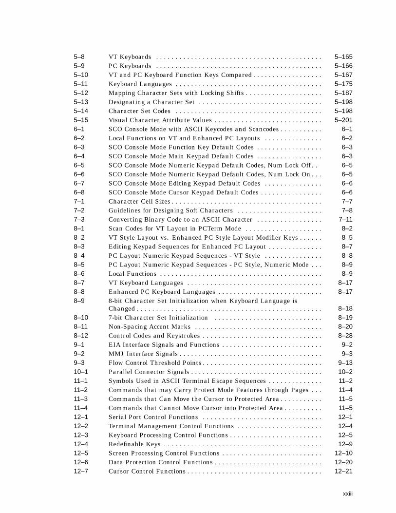
5–8 VT Keyboards . . . . . . . . . . . . . . . . . . . . . . . . . . . . . . . . . . . . . . . . . . . 5–1655–9 PC Keyboards . . . . . . . . . . . . . . . . . . . . . . . . . . . . . . . . . . . . . . . . . . . 5–1665–10 VT and PC Keyboard Function Keys Compared . . . . . . . . . . . . . . . . . . 5–1675–11 Keyboard Languages . . . . . . . . . . . . . . . . . . . . . . . . . . . . . . . . . . . . . . 5–1755–12 Mapping Character Sets with Locking Shifts . . . . . . . . . . . . . . . . . . . . 5–1875–13 Designating a Character Set . . . . . . . . . . . . . . . . . . . . . . . . . . . . . . . . 5–1985–14 Character Set Codes . . . . . . . . . . . . . . . . . . . . . . . . . . . . . . . . . . . . . . 5–1985–15 Visual Character Attribute Values . . . . . . . . . . . . . . . . . . . . . . . . . . . . 5–2016–1 SCO Console Mode with ASCII Keycodes and Scancodes . . . . . . . . . . . 6–16–2 Local Functions on VT and Enhanced PC Layouts . . . . . . . . . . . . . . . 6–26–3 SCO Console Mode Function Key Default Codes . . . . . . . . . . . . . . . . . 6–36–4 SCO Console Mode Main Keypad Default Codes . . . . . . . . . . . . . . . . . 6–36–5 SCO Console Mode Numeric Keypad Default Codes, Num Lock Off . . 6–56–6 SCO Console Mode Numeric Keypad Default Codes, Num Lock On . . . 6–56–7 SCO Console Mode Editing Keypad Default Codes . . . . . . . . . . . . . . . 6–66–8 SCO Console Mode Cursor Keypad Default Codes . . . . . . . . . . . . . . . . 6–67–1 Character Cell Sizes . . . . . . . . . . . . . . . . . . . . . . . . . . . . . . . . . . . . . . . 7–77–2 Guidelines for Designing Soft Characters . . . . . . . . . . . . . . . . . . . . . . 7–87–3 Converting Binary Code to an ASCII Character . . . . . . . . . . . . . . . . . 7–118–1 Scan Codes for VT Layout in PCTerm Mode . . . . . . . . . . . . . . . . . . . . 8–28–2 VT Style Layout vs. Enhanced PC Style Layout Modifier Keys . . . . . . 8–58–3 Editing Keypad Sequences for Enhanced PC Layout . . . . . . . . . . . . . . 8–78–4 PC Layout Numeric Keypad Sequences - VT Style . . . . . . . . . . . . . . . 8–88–5 PC Layout Numeric Keypad Sequences - PC Style, Numeric Mode . . . 8–98–6 Local Functions . . . . . . . . . . . . . . . . . . . . . . . . . . . . . . . . . . . . . . . . . . 8–98–7 VT Keyboard Languages . . . . . . . . . . . . . . . . . . . . . . . . . . . . . . . . . . . 8–178–8 Enhanced PC Keyboard Languages . . . . . . . . . . . . . . . . . . . . . . . . . . . 8–178–9 8-bit Character Set Initialization when Keyboard Language is
Changed . . . . . . . . . . . . . . . . . . . . . . . . . . . . . . . . . . . . . . . . . . . . . . . . 8–188–10 7-bit Character Set Initialization . . . . . . . . . . . . . . . . . . . . . . . . . . . . 8–198–11 Non-Spacing Accent Marks . . . . . . . . . . . . . . . . . . . . . . . . . . . . . . . . . 8–208–12 Control Codes and Keystrokes . . . . . . . . . . . . . . . . . . . . . . . . . . . . . . . 8–289–1 EIA Interface Signals and Functions . . . . . . . . . . . . . . . . . . . . . . . . . . 9–29–2 MMJ Interface Signals . . . . . . . . . . . . . . . . . . . . . . . . . . . . . . . . . . . . . 9–39–3 Flow Control Threshold Points . . . . . . . . . . . . . . . . . . . . . . . . . . . . . . . 9–1310–1 Parallel Connector Signals . . . . . . . . . . . . . . . . . . . . . . . . . . . . . . . . . . 10–211–1 Symbols Used in ASCII Terminal Escape Sequences . . . . . . . . . . . . . . 11–211–2 Commands that may Carry Protect Mode Features through Pages . . . 11–411–3 Commands that Can Move the Cursor to Protected Area . . . . . . . . . . . 11–511–4 Commands that Cannot Move Cursor into Protected Area . . . . . . . . . . 11–512–1 Serial Port Control Functions . . . . . . . . . . . . . . . . . . . . . . . . . . . . . . . 12–112–2 Terminal Management Control Functions . . . . . . . . . . . . . . . . . . . . . . 12–412–3 Keyboard Processing Control Functions . . . . . . . . . . . . . . . . . . . . . . . . 12–512–4 Redefinable Keys . . . . . . . . . . . . . . . . . . . . . . . . . . . . . . . . . . . . . . . . . 12–912–5 Screen Processing Control Functions . . . . . . . . . . . . . . . . . . . . . . . . . . 12–1012–6 Data Protection Control Functions . . . . . . . . . . . . . . . . . . . . . . . . . . . . 12–2012–7 Cursor Control Functions . . . . . . . . . . . . . . . . . . . . . . . . . . . . . . . . . . . 12–21
xxiii

12–8 ASCII Editing Control Functions . . . . . . . . . . . . . . . . . . . . . . . . . . . . . 12–2512–9 Local Edit Mode Function Keys . . . . . . . . . . . . . . . . . . . . . . . . . . . . . . 12–2512–10 Tab Stop Control Functions . . . . . . . . . . . . . . . . . . . . . . . . . . . . . . . . . 12–2612–11 Page Edit Control Functions . . . . . . . . . . . . . . . . . . . . . . . . . . . . . . . . 12–2712–12 Rules for Locating Rectangle . . . . . . . . . . . . . . . . . . . . . . . . . . . . . . . . 12–2912–13 Rectangle Area Control Functions . . . . . . . . . . . . . . . . . . . . . . . . . . . . 12–3012–14 Send Data Delimiters . . . . . . . . . . . . . . . . . . . . . . . . . . . . . . . . . . . . . . 12–3212–15 Delimiters for Other Personalities . . . . . . . . . . . . . . . . . . . . . . . . . . . . 12–3312–16 Print/Send Control Functions . . . . . . . . . . . . . . . . . . . . . . . . . . . . . . . . 12–3312–17 Printing Data Control Functions . . . . . . . . . . . . . . . . . . . . . . . . . . . . . 12–3512–18 Graphic Characters . . . . . . . . . . . . . . . . . . . . . . . . . . . . . . . . . . . . . . . 12–3613–1 Display and Load Character Sets . . . . . . . . . . . . . . . . . . . . . . . . . . . . 13–113–2 Loading Font Bank . . . . . . . . . . . . . . . . . . . . . . . . . . . . . . . . . . . . . . . 13–313–3 Design a Character Font . . . . . . . . . . . . . . . . . . . . . . . . . . . . . . . . . . . 13–5A–1 VT Keyboard Non-Spacing Diacritical Marks . . . . . . . . . . . . . . . . . . . . A–1B–1 Enhanced PC Keyboard Non-Spacing Diacritical Marks . . . . . . . . . . . B–1C–1 WYSE and TVI Modes Function Keys for PC Keyboard . . . . . . . . . . . . C–1C–2 WYSE and TVI Modes Function Keys for PC Keyboard . . . . . . . . . . . . C–1C–3 WYSE and TVI Modes Editing Keys for PC Keyboard . . . . . . . . . . . . . C–2C–4 WYSE and TVI Modes Cursor Keys on PC Keyboard . . . . . . . . . . . . . C–2C–5 WYSE and TVI Modes Numeric Keys for PC Keyboard, NumLock =
Off . . . . . . . . . . . . . . . . . . . . . . . . . . . . . . . . . . . . . . . . . . . . . . . . . . . . C–2C–6 WYSE 160 and TVI Modes Numeric Keys for PC Keyboard, NumLock
= On . . . . . . . . . . . . . . . . . . . . . . . . . . . . . . . . . . . . . . . . . . . . . . . . . . . C–3C–7 ADDS A2 Function Keys on PC Keyboard . . . . . . . . . . . . . . . . . . . . . . C–3C–8 ADDS A2 Editing Keys on PC Keyboard . . . . . . . . . . . . . . . . . . . . . . . C–4C–9 ADDS A2 Cursor Keys on PC Keyboard . . . . . . . . . . . . . . . . . . . . . . . . C–4C–10 ADDS A2 Mode Numeric Keypad Keys on PC Keyboard; NumLock =
Off . . . . . . . . . . . . . . . . . . . . . . . . . . . . . . . . . . . . . . . . . . . . . . . . . . . . C–4C–11 ADDS A2 Mode Numeric Keypad Keys on PC Keyboard; NumLock =
On . . . . . . . . . . . . . . . . . . . . . . . . . . . . . . . . . . . . . . . . . . . . . . . . . . . . C–5C–12 WYSE and TVI Modes Function Keys for DEC VT Keyboard . . . . . . . C–6C–13 WYSE and TVI Modes Editing Keys on DEC VT Keyboard . . . . . . . . . C–6C–14 WYSE and TVI Modes Cursor Keys on DEC VT Keyboard . . . . . . . . . C–7C–15 WYSE and TVI Modes Numeric Keypad PF Keys on DEC VT
Keyboard . . . . . . . . . . . . . . . . . . . . . . . . . . . . . . . . . . . . . . . . . . . . . . . C–7C–16 ADDS A2 Function Keys on DEC VT Keyboard . . . . . . . . . . . . . . . . . . C–7C–17 ADDS A2 Editing Keys on DEC VT Keyboard . . . . . . . . . . . . . . . . . . . C–8C–18 ADDS A2 Cursor Keys on DEC VT Keyboard . . . . . . . . . . . . . . . . . . . C–8C–19 ADDS A2 Numeric Keypad PFKeys on DEC VT Keyboard . . . . . . . . . C–8C–20 Local Functions in ASCII Code Mode . . . . . . . . . . . . . . . . . . . . . . . . . . C–9C–21 Local Functions in PC Scancode Mode . . . . . . . . . . . . . . . . . . . . . . . . . C–11E–1 ANSI Control Functions Index by Final Character . . . . . . . . . . . . . . . E–1
xxiv

Part IVT520 Video Terminal
This part includes the following chapters:
• Chapter 1, Overview
• Chapter 2, Set-Up
• Chapter 3, Desktop Features


1Overview
1.1 IntroductionThe VT520 is a low-cost, multi-session, text video terminal featuring enhancedkeyboard and communications flexibility, providing up to four sessions at a time.Two or more sessions can be assigned to the same communication port whenTerminal Device/Session Management Protocol (TD/SMP) is used to multiplex thesessions. Each session has its own framed window, window title, and icon name.
The VT520 has a define key editor that allows you to reprogram any key on thekeyboard.
The VT525 color terminal allows you to assign different colors to the variouswindows and to combinations of character attributes. You can select colors fromcolor look-up tables or create your own color combinations. Unless specificallymentioned in this manual the term VT520 also refers to the VT525 color model.
The product has a 25-pin stacked male/female RS-232 connector (EIA-232),two 6-pin EIA-423 (MMJ) connectors, and a Centronics parallel connector. TheRS-232 and the EIA-423 ports are used.
The VT520 also has power management features that exceed the EnvironmentalProtection Agency (EPA) Energy Star requirements for saving energy.
1.2 Communications FeaturesThe terminal provides:
• Three bidirectional, asynchronous serial communication ports; one of which(Comm 3) can be used for a local printer.
• Baud rates from 300 to 115.2K baud
• Centronics parallel printer port
• 25-pin serial connectors
• Two MMJ serial connectors
• Expanded flow control options:
- Software flow control using XON/XOFF or XPC- Hardware flow control using DTR/DSR
Overview 1–1
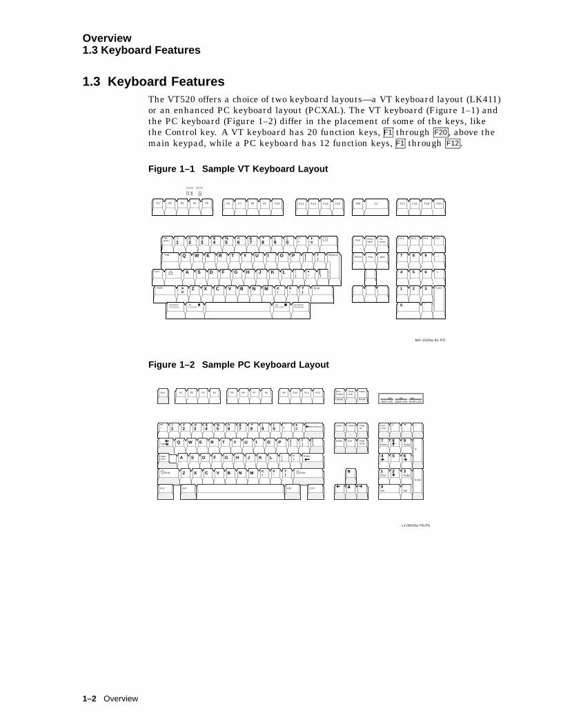
Overview1.3 Keyboard Features
1.3 Keyboard FeaturesThe VT520 offers a choice of two keyboard layouts—a VT keyboard layout (LK411)or an enhanced PC keyboard layout (PCXAL). The VT keyboard (Figure 1–1) andthe PC keyboard (Figure 1–2) differ in the placement of some of the keys, likethe Control key. A VT keyboard has 20 function keys, F1 through F20 , above themain keypad, while a PC keyboard has 12 function keys, F1 through F12 .
Figure 1–1 Sample VT Keyboard Layout
X
Z X C V B N
A S D F G H J K L
I O PT Y UW E R
M
Q
1 2 3 4 5 6 7 8 9 0! # $ % ^ & * ( )a
><
Return
Shift?/.,
:; "
’|\
}]
-- +
=
}]
Help Do
Prev Next
Re-move
InsertHere
Find
Select
PF1 PF2 PF3
Enter
54
7 8 9 _
,6
321
0 .
PF4~
Ctrl
Tab
Shift
AltFunction
ComposeCharacter
AltFunction
ComposeCharacter
F1 F2 F3 F4 F5 F6 F7 F8 F9 F10 F11 F12 F13 F14 F17 F18 F19 F20
(ESC)
North American/United Kingdom (Word Processing Version)
><
MA-1520a-92.PS
Figure 1–2 Sample PC Keyboard Layout
PageUp
HomeInsert
Esc F1 F2 F3 F4 F5 F6 F7 F8 F9 F10 F11 F12 PrintScreen
ScrollLock
SetUp Break
Pause
PageDown
EndDelete
BackSpace1 2 3 4 5 6 7 8 9 0! # $ % ^ & * ( )a
- +=
~
Z X C V B N
A S D F G H J K L
I O PT Y UW E R
M
Q
?/.,
:; "
’
}]
Caps
Tab
Shift ><
Ctrl Ctrl
_
Home PgUp
_/
PgDnEnd
Ins Del
NumLock
7 8 9
4 5 6
321
0 .
+
Enter
*
G S F - M K 2 5 1 0 - 2 9 - D G
North American
Num Lock Caps Lock Scroll Lock
Alt Alt l
LJ-00226a-TI0.PS
LockEnter
|\
}]
Shift
d i ig t a l
1–2 Overview
Overview1.3 Keyboard Features
The keyboard has the following features:
• An IBM PS/2-compatible 6-pin mini DIN connector.
• Keyboard keys that can be reprogrammed to send single characters, to sendcharacter sequences, or to invoke local functions (Hold, Copy and Paste,Remove, Insert, Print Page, Toggle Autoprint, Set-Up, Break, and so on).
• A local user-defined key editor. Key definitions can be saved in nonvolatilememory.
• Eight levels of user-defined function keys using any combination of Shift,Control, and Alt.
• 971 bytes of nonvolatile memory available for custom user-defined keys(UDKs)/Session, which cannot be reallocated. The maximum length for aUDK definition is 255 bytes.
1.4 Printer Port FeaturesThe terminal has the following printer port features:
• A Centronics parallel printer port.
• IBM ProPrinter support.
• Bidirectional serial communication ports.
• Baud rates from 300 to 115.2K baud.
• Null characters that can pass as data to the printer port.
1.5 Display and Text CapabilitiesThe terminal has both ANSI and ASCII display and text processing capabilities.The features of each are listed below.
1.5.1 ANSI
• Macro capability
• Display: 26, 42, or 53 data lines
• Selectable page size: 24, 25, 36, 42, 48, 50, or 72 lines
• Full status line (occupies one data line)
• Separate keyboard indicator line
• Three pages of 24 lines
• SCO Console mode
1.5.2 ASCII
• Terminal emulations:WYSE: 325 (color model only), 50, 50+, 60 native, 160 text only, 120, 150,PCTermTelevideo: TVI 950, 925, 910+Applied Digital Data Systems: ADDS A2
• Dim and invisible character attributes
Overview 1–3
Overview1.6 Enhanced Set-Up
1.6 Enhanced Set-UpThe terminal provides an enhanced menu-based Set-Up, allowing commonfeatures to be accessed easily from a single screen. All Set-Up features are hostcontrollable to allow remote configuration. The terminal also has a means to lockout the local setup key.
Set-Up menus are available in English, French, German, Italian, or Spanish. Fordetails, see Chapter 2, Set-Up.
1.7 Desktop Productivity FeaturesThe terminal has the following desktop productivity features:
• Local copy and paste (not available in PCTerm mode)
• Time of day clock (host or locally set, no battery back up)
• Desktop calculator with decimal, octal, and hex conversions
• Display character set tables.
• Review previous data lines.
For details, see Chapter 3, Desktop Features.
1.8 Character Set SupportIn addition to the traditional Digital graphic character sets (DEC Multinational,NRCS, and so on), the VT520 supports Cyrillic, Greek, Hebrew, Turkish, mostEastern European languages, and PC character sets. For details, see Chapter 7,Character Sets.
1.9 Ergonomics (Human Factors) FeaturesThe terminal is designed to provide a high-quality human interface and long-term reliability at low cost. The VT520 offers 72 Hz refresh, full overscan. Theterminal has the following features:
• 35.5 cm (14 in) flat face, antiglare CRT screen
• Improved resolution of 802 � 480 pixels. (The mono VT520 also has 800 �432 with overscan.)
• 72 Hz refresh
• Overscan1
• Additional fonts (see Table 1–1)
• Tilt/swivel base
• Choice of keyboards
• Accessibility aids
1 Not available in color model.
1–4 Overview

Overview1.9 Ergonomics (Human Factors) Features
Table 1–1 VT520/25 Font Sizes
80 Columns 132 Columns Maximum Number of Lines
10 � 16 6 � 16 26 lines + keyboard indicator line
10 � 10 6 � 10 42 lines + keyboard indicator line
10 � 8 6 � 8 53 lines + keyboard indicator line
1.10 Field-Upgradable FirmwareAll VT520 models include support for a 4 Mbit (512 KByte) ROM cartridge option.The base unit comes with a factory-installed ROM. The ROM cartridge connectoris protected by a ROM cartridge cover. To install new code, the ROM cartridgecover is removed, and a ROM cartridge with attached cover is plugged into theROM connector. The new code completely supersedes the factory-installed ROMcode. It does not overlay or extend the factory code.
Note
If you service the terminal with a ROM cartridge installed, turn thepower Off, and remove and save the ROM cartridge to put it on the newterminal.
To install a ROM cartridge with new firmware, use the following steps:
1. Turn the power off before installing the ROM cartridge.
2. Turn the power on and press F3 .
3. Select Actions . Restore factory defaults and press Return .
4. Select Sessions . Save all sessions and press Return .
The installation is now complete. When you power-on the terminal, the message‘‘ROM card active’’ is displayed in the upper-left corner of the display. Note thatsteps 3 and 4 are necessary to initialize the terminal’s non-volatile memory foruse with the ROM cartridge firmware. Failure to perform these steps may causethe terminal to report an NVR error.
Overview 1–5

Overview1.11 Comparison with previous VT Terminals
1.11 Comparison with previous VT TerminalsThe VT520 is functionally compatible with other ANSI products with thefollowing exceptions:
• Terminal ID
The Primary Device Attributes can report additional extensions to covernew features. See Chapter 4 for a summary of the control functions. TheSecondary Device Attributes are different.
VT520 CSI > 64 ; Pv ; 0 cVT525 CSI > 65 ; Pv ; 0 c
Where Pv is the firmware version number.
• Dynamically Redefinable Character Set (DRCS) Fonts
The VT520 has four buffers, which can load up to two dynamically redefinablecharacter sets, each with an 80-column font and a 132-column font.
• Keyboards
VT420 keyboards cannot be used on the VT520; however, the VT520 canemulate the VT420 keyboard behavior when configured accordingly.
• Four Sessions
The VT520 is a multi-session terminal. You can have up to foursessions enabled. More than one session can be established on the samecommunication port.
• PC Character Sets
PC character sets are available in PC Term and SCO Console mode only.
1–6 Overview

2Set-Up
This chapter describes VT520 Set-Up features. Set-Up is used to examine orchange terminal operating features, such as transmit/receive speeds, type ofcursor, or key definitions.
2.1 Entering Set-UpYou enter Set-Up by pressing the key designated as the Set-Up key. Pressing thiskey alternately places the terminal in Set-Up mode or returns it to the operatingmode.
On a . . . The Set-Up key is . . .
VT keyboard F3 on the top row.
SCO Console mode Caps Lock F3
PC keyboard Caps Lock Print Screen
or Alt Print Screen .
Figure 2–1 Set-Up
MA049193.GRA
The Set-Up display consists of pull-right menus. You can move back and forthwith the arrow keys. Pressing Enter , Return , Do , or Select invokes the action orsetting for the current menu item.
The Set-Up function may be reassigned to other key combinations or can bedisabled it for local entry into Set-Up. When you press F3 as the first keyafter the terminal is powered on, you always enter Set-Up, regardless of whichkeyboard you use or how F3 is defined.
Set-Up 2–1

Set-Up2.1 Entering Set-Up
2.1.1 Effects of Entering Set-UpPlacing the terminal in Set-Up mode causes no loss of data if a Flow Controlprotocol is in use on the communications port. The first Set-Up menu is displayedon the screen. Upon exiting Set-Up, the previous text is restored.
Entering Set-Up has the following side effects:
• Any compose sequence in progress is aborted and the keyboard is unlocked.
• A Set-Up Summary Line is displayed.
• Press Shift to show the Indicator Status Line.
• Printer operations are suspended and are resumed upon exiting Set-Up.
2.1.2 Set-Up LanguagesThe VT520 Set-Up menus can be displayed in five languages using a Set-Upfeature. A menu allows you to choose the language in which all subsequentSet-Up menus and displays are written. Selections from this Set-Up languagemenu (Figure 2–2) take effect immediately. This feature can also be invoked byDECSSL.
Figure 2–2 Set-Up Language Selection
2.1.3 Power-On Settings and DefaultsThe VT520 terminal stores many of its feature settings in nonvolatile memory(NVM). Nonvolatile memory retains these settings even when power is shutoff. In addition to storing operator-selected features, the terminal retains thefactory default settings in permanent memory. By using Set-Up, you can modifyindividual terminal features, recall the feature settings stored in nonvolatilememory, or recall the factory default settings.
In this chapter, the defaults are shown with a solid bullet (�) in lists and inboldface in text.
2–2 Set-Up
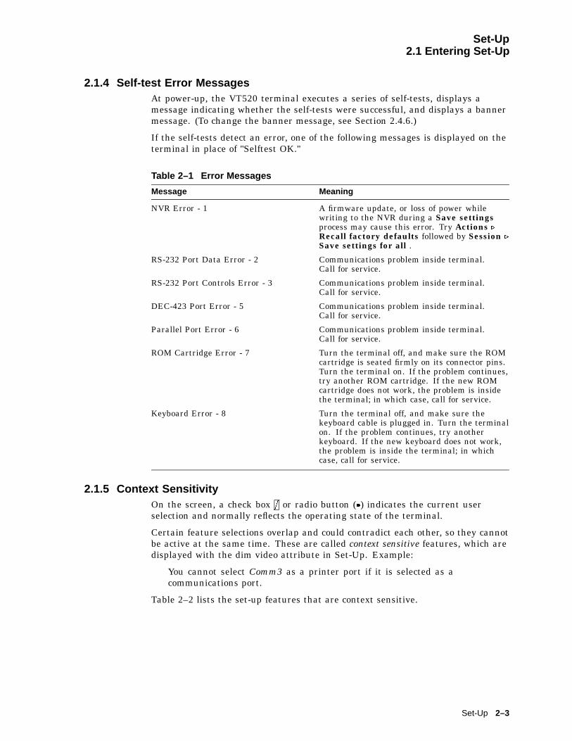
Set-Up2.1 Entering Set-Up
2.1.4 Self-test Error MessagesAt power-up, the VT520 terminal executes a series of self-tests, displays amessage indicating whether the self-tests were successful, and displays a bannermessage. (To change the banner message, see Section 2.4.6.)
If the self-tests detect an error, one of the following messages is displayed on theterminal in place of "Selftest OK."
Table 2–1 Error Messages
Message Meaning
NVR Error - 1 A firmware update, or loss of power whilewriting to the NVR during a Save settingsprocess may cause this error. Try Actions .
Recall factory defaults followed by Session .
Save settings for all .
RS-232 Port Data Error - 2 Communications problem inside terminal.Call for service.
RS-232 Port Controls Error - 3 Communications problem inside terminal.Call for service.
DEC-423 Port Error - 5 Communications problem inside terminal.Call for service.
Parallel Port Error - 6 Communications problem inside terminal.Call for service.
ROM Cartridge Error - 7 Turn the terminal off, and make sure the ROMcartridge is seated firmly on its connector pins.Turn the terminal on. If the problem continues,try another ROM cartridge. If the new ROMcartridge does not work, the problem is insidethe terminal; in which case, call for service.
Keyboard Error - 8 Turn the terminal off, and make sure thekeyboard cable is plugged in. Turn the terminalon. If the problem continues, try anotherkeyboard. If the new keyboard does not work,the problem is inside the terminal; in whichcase, call for service.
2.1.5 Context SensitivityOn the screen, a check box = or radio button (�) indicates the current userselection and normally reflects the operating state of the terminal.
Certain feature selections overlap and could contradict each other, so they cannotbe active at the same time. These are called context sensitive features, which aredisplayed with the dim video attribute in Set-Up. Example:
You cannot select Comm3 as a printer port if it is selected as acommunications port.
Table 2–2 lists the set-up features that are context sensitive.
Set-Up 2–3

Set-Up2.1 Entering Set-Up
Table 2–2 Context Sensitive Set-Up Features
Menu Item Dimmed when . . .
Session . Pages per session Pagememory allocation
Page selection exceed the number of unassignedpages available.
Display . Lines per screenLines per page
Sizes are not available based on the current pagememory allocation.WYSE is selected; use ASCII emulation . Datalines and Pages.
Cursor direction Keyboard language is not Hebrew.
Energy saver CRT saver = never is selected.
Overscan Terminal is a color terminal.
Color . ASCII color mode, Reverseand blank attributes, andIntensity attributes
Emulation mode is set to other than an ASCIIterminal emulation.
Alternate text colors... Select color mode is other than Alternate color.
Select color mode Terminal type . Emulation mode is other than aVT or SCO console.
Terminal type . Terminal ID to host Terminal type . Emulation mode is other than aVT or SCO console.
= 7-bit NRCS characters Emulation mode is set to VT100/VT52; orCommunication . Word size is 7-bits; or no8-bit NRC set exists for the keyboard language.
ASCII emulation . Terminal type . Emulation mode is set to VT orSCO console.
TVI page-flip Terminal type . Emulation mode is other thanTVI.
Keyboard . Key encoding .
Character, Scan code andKey position
ASCII emulation is selected, or a PC keyboard isconnected.
Data processing keys A PC keyboard is connected.
Map PC keyboard to VT The keyboard is not a PC keyboard.
Communication . Port select Comm3 Comm3 is selected as a communications port. (Itcan be either a comm port or a printer port but notboth.)
Half duplex The host Communication . Port select is set toS1=comm2.
Transmit flow control .
DSR and BothThe Modem . Enable modem control is selected.
Receive flow control .
DTR and BothThe Modem . Enable modem control is selected.
Modem . Disconnect delay andModem speed
The Modem . Enable modem control is notselected.
Printer . Serial print speed,2-way communication,Transmit flow control,Receive flow control, Wordsize, Parity, and Stop bits
The Communication . Port select is set to one ofthe Print = parallel selections.
DEC/ISO char sets IBM ProPrinter is selected.
PC character sets DEC ANSI printer is selected.
Print mode . Controller Display . Show control characters is selected.
2–4 Set-Up
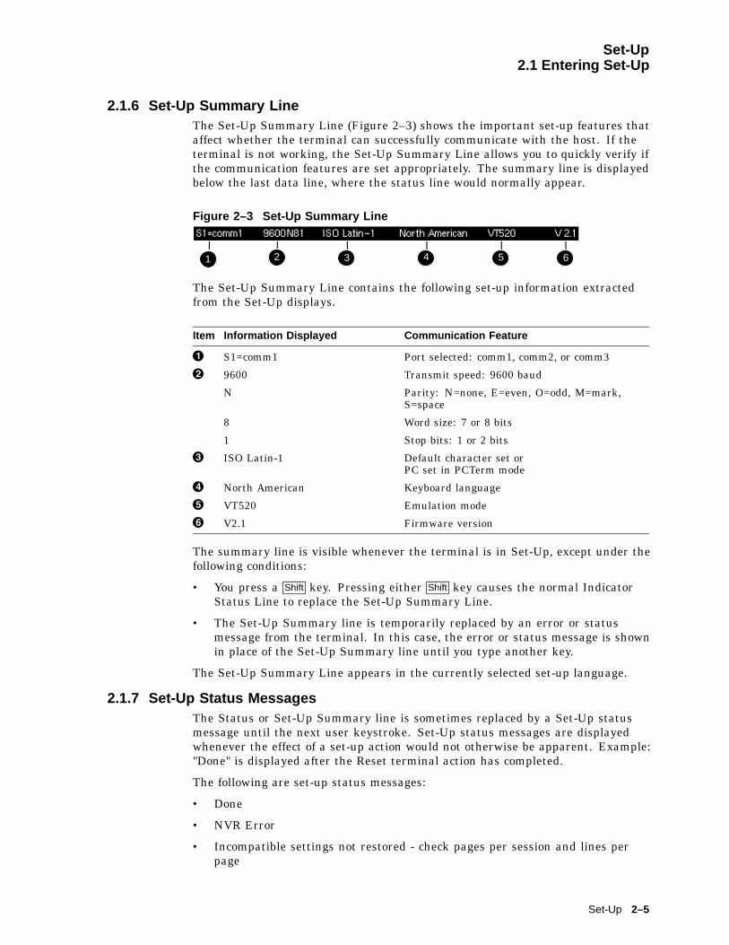
Set-Up2.1 Entering Set-Up
2.1.6 Set-Up Summary LineThe Set-Up Summary Line (Figure 2–3) shows the important set-up features thataffect whether the terminal can successfully communicate with the host. If theterminal is not working, the Set-Up Summary Line allows you to quickly verify ifthe communication features are set appropriately. The summary line is displayedbelow the last data line, where the status line would normally appear.
Figure 2–3 Set-Up Summary Line
111 2 3 4 5 6
The Set-Up Summary Line contains the following set-up information extractedfrom the Set-Up displays.
Item Information Displayed Communication Feature
! S1=comm1 Port selected: comm1, comm2, or comm3
" 9600 Transmit speed: 9600 baud
N Parity: N=none, E=even, O=odd, M=mark,S=space
8 Word size: 7 or 8 bits
1 Stop bits: 1 or 2 bits
# ISO Latin-1 Default character set orPC set in PCTerm mode
$ North American Keyboard language
% VT520 Emulation mode
& V2.1 Firmware version
The summary line is visible whenever the terminal is in Set-Up, except under thefollowing conditions:
• You press a Shift key. Pressing either Shift key causes the normal IndicatorStatus Line to replace the Set-Up Summary Line.
• The Set-Up Summary line is temporarily replaced by an error or statusmessage from the terminal. In this case, the error or status message is shownin place of the Set-Up Summary line until you type another key.
The Set-Up Summary Line appears in the currently selected set-up language.
2.1.7 Set-Up Status MessagesThe Status or Set-Up Summary line is sometimes replaced by a Set-Up statusmessage until the next user keystroke. Set-Up status messages are displayedwhenever the effect of a set-up action would not otherwise be apparent. Example:"Done" is displayed after the Reset terminal action has completed.
The following are set-up status messages:
• Done
• NVR Error
• Incompatible settings not restored - check pages per session and lines perpage
Set-Up 2–5

Set-Up2.1 Entering Set-Up
• Incompatible settings not restored - check comm port selection
• Page memory reallocated
• Sessions not enabled - No Session Management response from host
• Session # terminated abnormally
• Insufficient terminal resources to open Session
• Sessions not enabled - Unable to run with host Session Management version
• Session open request pending
• Session opened
• No response from host for Session Management
• Data overrun occurred on Session #
• Sessions not enabled - Sessions not selected
• Session # terminated normally
• Insufficient host resources to open Session
• Sessions disabled
• Sessions enabled - Restoring previous sessions
Set-Up functions that require additional time to process display the message‘‘Please wait’’ until they have completed. Save settings for all and Restoresettings for all display this message.
2.1.8 Status LineThe VT520 terminal has a status display with the following features:
• The clock time appears on the status display if the local clock has beeninitialized since the terminal was last powered on.
• In the ASCII emulation modes, the host-writable status line becomes theWYSE Editing status line.
• When enabled, the Accessibility Aids feature ("sticky keys") displays icons inthe Keyboard Indicator line. For details, see Section 8.11.2.
The VT520 Indicator status line includes the Active Position Indicator, PrinterStatus Indicator, Modem Status Indicator, and local clock time in the desiredformat. Example:
1(24,008) Printer: None Modem: DSR 3:15 PM
2.1.9 Keyboard Indicator LineThe Keyboard Indicator Line has the following features:
• It is displayed in the Set-Up language.
• It has active keyboard layout. Nothing is displayed for Group 1. "G2" isdisplayed for Group 2, along with a small icon representing the right side ofthe top of the keycap. (To see this icon, press Ctrl/Alt/F2 . To return from Group2, press Ctrl/Alt/F1 .)
• For Greek, Hebrew, and Russian, "G2" is replaced by "Grk", "Heb", and "Rus",respectively.
2–6 Set-Up
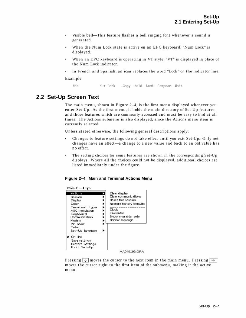
Set-Up2.1 Entering Set-Up
• Visible bell—This feature flashes a bell ringing font whenever a sound isgenerated.
• When the Num Lock state is active on an EPC keyboard, "Num Lock" isdisplayed.
• When an EPC keyboard is operating in VT style, "VT" is displayed in place ofthe Num Lock indicator.
• In French and Spanish, an icon replaces the word "Lock" on the indicator line.
Example:
Heb Num Lock Copy Hold Lock Compose Wait
2.2 Set-Up Screen TextThe main menu, shown in Figure 2–4, is the first menu displayed whenever youenter Set-Up. As the first menu, it holds the main directory of Set-Up featuresand those features which are commonly accessed and must be easy to find at alltimes. The Actions submenu is also displayed, since the Actions menu item iscurrently selected.
Unless stated otherwise, the following general descriptions apply:
• Changes to feature settings do not take effect until you exit Set-Up. Only netchanges have an effect—a change to a new value and back to an old value hasno effect.
• The setting choices for some features are shown in the corresponding Set-Updisplays. Where all the choices could not be displayed, additional choices arelisted immediately under the figure.
Figure 2–4 Main and Terminal Actions Menu
MA049193.GRA
Pressing + moves the cursor to the next item in the main menu. Pressing )
moves the cursor right to the first item of the submenu, making it the activemenu.
Set-Up 2–7

Set-Up2.3 Main Menu
2.3 Main MenuThe following descriptions refer to Figure 2–4.
The items above the dividing line in the main menu form a directory to the majorfunctional areas of set-up features. Each item has a corresponding submenu ordialog box.
Pressing the Set-Up key from within a dialog box will flash the OK button as if itwere pressed and accept the corresponding changes before exiting Set-Up.
Below the dividing line are features that need to be easy to find from any menu.
2.3.1 On-LineThe On-line feature allows you to select whether the terminal directs keyboardinput to its host port UART to communicate with a remote host (On-Line), ordirects keyboard input directly to the screen (receive character parser) withoutsending to a remote host (off-line or local).
Note
The On-line selection is different from the Local echo mode in theCommunications Set-Up submenu. When On-line is disabled (localmode), nothing is sent to the host. Any keyboard input is directed to thereceive character parser, which updates the screen.
In contrast, Local echo causes characters sent to the host port to alsobe directed back to the receive character parser, as if they had beenreceived (echoed) from the host. Local echo is temporarily disabled whenthe terminal is in either Local mode or Local Controller mode, becausekeyboard input is already being redirected to the screen or printer port.
If an NVR error occurs during power-up, the terminal switches to Localmode.
Terminal reports, such as Answerback, DA, CPR, DECTSR, DECRPM, DECRPSS,DECAUPSS, DECCIR, DECTABSR and DSR, are not directed to the display.While in "local", host communications are put on "hold": All data received isbuffered. If necessary, an XOFF is sent (or DTR is deasserted) to prevent bufferoverflow. This buffered data is directed to the display when On-line mode isreentered. Note that the received character buffer (silo) is responsible for sendingXON and XOFF when needed, not the On-line/Local state.
When in Local mode, modem signals, including DTR, are unaffected. Nodisconnect is performed. The functions of the printer port remain unchangedin Local mode. They function the same as in On-line mode.
When in Local mode and Printer To Host mode is selected, data from the printerport is displayed on the video terminal.
When both Local mode and Printer Controller mode are selected, the terminalis in Local Controller mode. Keyboard characters are sent to the printer port.Note that in "regular local" mode, any keyboard output is directed to the screen,but in "regular controller" mode, the keyboard output is directed at the hostport. When Local Controller mode is exited to Local mode, the terminal redirectskeyboard output from the printer to the screen (and parser). When you changefrom Local Controller mode to Printer Controller mode, the terminal transmitsthe characters accumulated in the receive silo to the printer.
2–8 Set-Up

Set-Up2.3 Main Menu
2.3.2 Save SettingsThe Save settings menu item, when invoked by pressing Return or Enter ,causes the settings for most Set-Up controlled operating features to be saved innonvolatile memory, where they become the power-on settings.
The following settings are not saved.
• Keyboard encoding mode
• Application cursor keys when set by a host control function.
• Application keypad mode when set by a host control function.
2.3.3 Restore SettingsRestore settings is an action field that is used to replace all saved Set-Upparameters with the values stored in the NVR. As a side effect, this featureperforms a disconnect sequence, clears the screen, reinitializes the user-definablekeys (as saved), clears the soft character set, returns the cursor to the upperleft corner, aborts any print operation in progress, aborts ESC, CSI, and DCSsequences (and control strings), and shows "Done" on the status line. This actioncan also be invoked by the RIS control function.
2.3.4 Exit Set-UpThe Exit Set-Up menu item, when invoked by pressing Enter , causes the terminalto exit Set-Up. The effect is identical to pressing the Set-Up key while in Set-Up.
2.4 Actions MenuThe following descriptions refer to Figure 2–4. Certain Set-Up features instructthe terminal to perform an immediate action when they are invoked. Thesefeatures are grouped in the terminal Actions menu.
2.4.1 Clear DisplayThe Clear display feature clears the active page (including the lines which havetemporarily disappeared while the you are in Set-Up).
2.4.2 Clear CommunicationsThis feature is used to clear communication buffers and flags. It does not affectthe On-Line/Local state. It is not invoked by any control functions.
Clear communications:
• Aborts any print operation in progress
• Aborts any escape sequence, control sequence, control string, or characterstring processing (ESC, CSI, DCS, APC, OSC, PM, SOS)
• Clears the keyboard buffers
• Clears the receive silo
• Clears the transmit silo
• Takes the terminal out of Printer Controller mode
• Sends XON on to the host port
• Sends XON to the printer port if Printer To Host and XOFF are enabled
Set-Up 2–9

Set-Up2.4 Actions Menu
• Resets XOFF received flags on both ports
• Does not clear the screen
• Clears KAM locked condition
• Clears the "printer port has seen DSR since power up" flag. When in Set-Up,Ctrl Enter disables sessions and clears TD/SMP.
2.4.3 Reset this SessionThe Reset this session menu selection only resets the active session.
To . . . Press . . .
Reset all four sessions, Control Reset this session.
Perform a power-up reset, Control Set-Up from within Set-Up.
The Reset this session Set-Up feature resets the terminal to a "known state."This function is like Soft Terminal Reset (DECSTR), except DECSTR resets theCharacter Set mode to "8-bit Characters" and Reset terminal does not.
Additions:
• Keyboard encoding is reset to "character."
• PCTerm mode is not selected.
Note
From Set-Up, a soft reset using Reset terminal always works regardlessof the terminal mode; but using mode changing control functions(DECSCL, S8C1T, S7C1T, DECANM), the soft reset is sometimes notperformed.
2.4.4 Restore Factory DefaultsThe Restore factory defaults menu selection restores the factory defaultsettings for all four sessions. There is no provision to restore factory defaultsto a single session. Restore settings on the main menu only restores the activesession’s settings from NVM.
As a side effect, Restore factory defaults does the following:
• Performs a disconnect sequence
• Clears the screen
• Reinitializes the user-definable keys
• Clears the soft font
• Returns the cursor to upper-left corner
• Aborts print operations in progress
• Aborts ESC, CSI and DCS sequences
• Displays the "Done" message on the status line
2–10 Set-Up

Set-Up2.4 Actions Menu
2.4.5 Clock, Calculator, Show Character SetsThe Clock, Calculator, and Show character sets menu items are used toinvoke the corresponding desktop productivity features. Refer to Chapter 3.
2.4.6 Banner MessageThe Banner message menu item invokes a dialog box with a 30-character limit.When this feature is selected, a dialog box is displayed with a reverse video textentry area 30 characters long. If a Banner message is currently defined, themessage is displayed in the text entry area. The <x or Delete key can then beused to delete backwards and enter a new Banner message.
All characters that can be generated by the keyboard are legal in this field(including primary and secondary keyboard language characters). As such, noerrors are reported, except when trying to enter more than 30 characters. In thiscase, the bell rings (if enabled), and no more characters are accepted. The factorydefault message is no message at all (a blank field).
From the Actions menu, select Banner message....
1. Press Return or Enter to display a dialog box.
2. Enter your banner message.
3. Press the + to select OK button.
4. Press Return or Enter to return to the Set-Up menu.
5. Use the Save settings menu item to save the Banner message.
2.5 Multiple SessionsMultiple sessions extends the VT520 to act like four terminals in one. A sessionis an active connection between the terminal and a host system. The SessionSet-Up menu controls the use of more than one session. See Figure 2–18.
The VT520 supports up to four sessions using virtual terminals. Each virtualterminal maintains the full keyboard and display state of a real physical terminalbut shares a single keyboard and display with other virtual terminals. Before youcan login using a virtual terminal, it must be connected to a host computer.
VT520 session virtual terminals can be connected directly to a host computerthrough any of the three serial communication ports on the back of the terminal.Since there are only three comm ports, this method alone can only support threesessions.
To use a fourth session or reduce the number of serial comm lines needed, morethan one session must be connected through a single comm port. The VT520allows this using a session management protocol, called TD/SMP (TerminalDevice/Session Management Protocol). TD/SMP allows two or more sessions toshare a single comm line, as long as the other end of the comm line supports theprotocol. To enable TD/SMP at the terminal, you simply assign more than onesession virtual terminal to the same comm port in Set-Up.
TD/SMP is standard on most terminal servers. If you are using a terminal server,check with its documentation to determine if it can run TD/SMP.
Set-Up 2–11
Set-Up2.5 Multiple Sessions
2.5.1 Enabling and Controlling the Session ConfigurationThe VT520 provides three serial communication ports which may be assigned tosession virtual terminals in any combination. When only one virtual terminalis assigned to a communications port, the terminal functions as a single sessionterminal. The other three session selections are dimmed. The single session maybe allocated 8 pages of 25 lines each by 80 or 132 columns. The color terminalsupports 9 pages.
As session virtual terminals are assigned to physical communication ports,the terminal’s firmware allocates the necessary structures to create the virtualterminals up to a maximum of four. When more than one virtual terminalis assigned to a single communication port, the Terminal Device/SessionManagement Protocol (TD/SMP) is used.
2.5.2 Multiple Sessions using a Terminal Server with TD/SMPProcedure:
1. At the Local> prompt, enter the following command:
Local> set port multi enable Return
2. Continue with your login procedure.
To permanently set a terminal server port to use TD/SMP, you would type:
Local> define port multi enable Return
2.5.3 Multiple Sessions using SSU Host SoftwareIf your VT520 is connected directly to a host computer without a terminal server,use can still use TD/SMP by running the Session Support Utility (SSU) on yourhost computer. On a system that has SSU software, such as OSF or OpenVMS,open the first session as follows:
$ mcr ssu Return
On an UNIX-style system, open the first using:
% ssu
2.5.4 Opening Another SessionOnce TD/SMP is enabled, you can open a new session and switch between themas follows:
1. Press the F4 (Session) key on a VT keyboard; or press Caps Lock 0 on thenumeric keypad on a PC keyboard.
F4 is used as the Session key on the VT keyboard (factory default). Forconsistency, Caps Lock F4 also works on the VT keyboard.
On Enhanced PC layout keyboards (PC style), Caps Lock F4
or Caps Lock Scroll Lock are used as the Session keystroke and may besubstituted for the VT Session key (F4) anywhere it is used.
2. To go directly to a particular session, press Caps Lock 1 , 2 , 3 or 4 on thenumeric keypad.
The currently selected session is indicated on the Set-Up Summary line alongwith its corresponding communications port assignment (S1=comm1 for example).
2–12 Set-Up
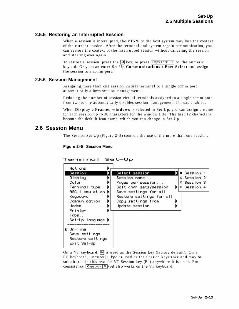
Set-Up2.5 Multiple Sessions
2.5.5 Restoring an Interrupted SessionWhen a session is interrupted, the VT520 or the host system may lose the contextof the current session. After the terminal and system regain communication, youcan restore the context of the interrupted session without canceling the sessionand starting over again.
To restore a session, press the F4 key; or press Caps Lock 0 on the numerickeypad. Or you can enter Set-Up Communications . Port Select and assignthe session to a comm port.
2.5.6 Session ManagementAssigning more than one session virtual terminal to a single comm portautomatically allows session management.
Reducing the number of session virtual terminals assigned to a single comm portfrom two to one automatically disables session management if it was enabled.
When Display . Framed windows is selected in Set-Up, you can assign a namefor each session up to 30 characters for the window title. The first 12 charactersbecome the default icon name, which you can change in Set-Up.
2.6 Session MenuThe Session Set-Up (Figure 2–5) controls the use of the more than one session.
Figure 2–5 Session Menu
On a VT keyboard, F4 is used as the Session key (factory default). On aPC keyboard, CapsLock 0 kpd is used as the Session keystroke and may besubstituted in this text for VT Session key (F4) anywhere it is used. Forconsistency, CapsLock 0 kpd also works on the VT keyboard.
Set-Up 2–13
Set-Up2.6 Session Menu
2.6.1 Select SessionThe Select session submenu is used to select the active session. All Set-Up selections apply to the currently active session. Most settings are keptindependently for each session and may be saved in non-volatile memory.Exceptions are made for settings that control the physical hardware that isshared between sessions. Example:
A single communications port cannot be used for both a session connectionand a printer port simultaneously.
The terminal ensures that conflicts like this do not happen by disabling(displaying as dim) or resetting certain selections. All such exceptions arenoted explicitly.
A disabled session has its session selection dimmed but can still be configured inSet-Up if it was active when Set-Up was entered. At least one session is alwaysenabled. If the currently active session is disabled, the previous enabled sessionbecomes the active session when you exit Set-Up.
While the terminal is in Set-Up, the Session key can be used to cycle betweensessions in order. You can also use CapsLock 1 kpd through CapsLock 4 kpd toselect enabled sessions explicitly. The currently selected session is indicated onthe Set-Up Summary line along with its corresponding communications portassignment (S1=comm1 for example).
Selecting a different session within Set-Up does not affect the active session atthe host until you exit Set-Up.
2.6.2 Session NameThe Enter session name dialog box allows a 30 character descriptive name to beentered for the active session. Depending on the windowing option selected, thisname is displayed with the corresponding session window to help you identifyeach session. See also Section 2.8.19.
Entering a session name is similar to entering an answerback message. A sessionname is not saved automatically; you must use the Save settings menu item.
Icon name — The first 12 characters of the session name is used as the iconname, but this name may be overwritten if a separate icon name is specifiedby a host control function. The session name is included as the "application_parameter" in the TD/SMP OPEN_SESSION command and may be used to selecta desired service.
2.6.3 Pages per SessionThe Pages per session dialog box displays a Session Page Memory Allocationscreen (Figure 2–6), which allows you to control how the terminal’s page memoryis allocated among the enabled sessions. The VT520 provides 8 pages of 25 linesby 80 or 132 columns as standard (9 pages on the color terminal). A disabledsession (Comm = session off) is dimmed and does not use any page memory.
Page selections which are not available in the current configuration are dimmedand cannot be selected. Thus, you may have to decrease the number of pagesassigned to one session before you can increase the number of pages assigned toanother. Any data on these pages is erased.
2–14 Set-Up

Set-Up2.6 Session Menu
Figure 2–6 Session Page Memory Allocation
The ‘‘� _ _pages’’ selections in Figure 2–6 allow you to enter a number of pagesnot shown as one of the other choices. The number in parenthesis below theseselections is maximum number of pages available to each session. When youselect this radio button, this maximum number is used as the number of pagesfor this session unless you enter a new value. Pressing Enter selects the radiobutton and maximum number of pages in a single operation. Alternatively, anynumber up to the maximum number of pages available can be typed in directly.
The maximum number of pages available to each session change as the allocationto other sessions changes. If only one session is enabled, the maximum numberof pages in a standard VT520 is 8.
A session that is currently disabled (Comm = session off) is dimmed and showsMax pages as zero to remind you that it is not using any page memory. (Zerois the factory default for S3 and S4.) A disabled session can be re-enabled atany time by assigning it to a communications port. When a disabled sessionis re-enabled, its initial page memory allocation is the previous allocation forthat session if available from the free resource pool; otherwise, it is one pageof 25 lines. If all pages are currently assigned, the terminal reduces by onethe allocation to the highest numbered session with more than one page. Thisautomatic adjustment of page allocation ensures that you can always enableanother session without worrying about memory management. If a sessionrequires a fixed number of pages for compatibility, you can assign that numberto S1 and S2. We recommend that you allocate page memory for the number ofsessions to be used ahead of time to avoid losing data in an existing session whencreating a new one.
Set-Up 2–15
Set-Up2.6 Session Menu
In case you cause the terminal to re-assign page memory while sessions are inuse, the pages assigned to a new session is first erased. If the cursor was on thatpage, it goes to page one. The terminal issues a warning message to indicatewhat may have changed for you to check, such as:
"Page memory reallocated, checkpages per session and lines perpage."
The terminal created a new session forcingpage memory to be re-allocated.
"Incompatible settings notrestored, check pages per sessionand lines per page."
The terminal is unable to copy or restore arequested setting.
2.6.4 Soft Character Sets/SessionThe Soft char sets/session submenu allows you to specify the allocation ofDRCS character set buffers to multiple sessions on the VT520 mono terminalonly.
• Two each S1 and S2 allocates two character set buffers each to S1 and S2making S1 and S2 compatible with terminals, like the VT510, VGB10, orWS510 video terminals. In this case, S3 and S4 do not support the DRCSextension, which is reported in their primary device attributes response.
• One each gives each session a single DRCS character set buffer making eachsession compatible with terminals, like the VT420.
This submenu is not included in the color terminal since it has enough memory togive all four sessions Two each.
2.6.5 Save Settings for All and Restore Settings for AllThe Save settings for all and Restore settings for all menu items are likethe Save settings and Restore settings items in the main menu except that theyoperate on all four sessions at once.
Since restoring settings for four sessions can take some time, the screen is clearedand a "Please wait" message is displayed in the center of the screen for onesecond to begin the restore operation. A "Done" or "Incompatible setting notrestored" message is displayed upon completion.
When restoring settings saved in non-volatile memory, it is possible that thenumber of pages saved for a session is larger than the number of pages availablein the free resource pool. In this case, the same approach is used as when asession is newly enabled. The process can be summarized as follows:
1. When restoring settings for more than one session, settings for each sessionare restored in order (S1, S2, S3, S4).
2. The saved page memory allocation is restored if that number of pages isavailable from the free resource pool, otherwise the page memory allocation isset to one page of 25 lines.
3. If no pages are available from the free resource pool, the terminal reduces byone the allocation to the highest numbered session with more than one page.
4. If a previously saved setting is not restored, the terminal displays theinformation message "Incompatible setting not restored, check pages persession and lines per page" on the error line. The message is cleared on thenext keystroke.
2–16 Set-Up

Set-Up2.6 Session Menu
The principle used is to restore all the settings possible, replace those individualsettings that can’t be restored with some reasonable default, and display theinformation message "Incompatible setting not restored..." if necessary. This sameprinciple is used in all cases where settings cannot be copied or restored due toresource limitations or conflicts with other settings.
The active session number is not saved in NVM. Restore settings for all does notchange the active session.
2.6.6 Copy Settings from MenuThe Copy settings from menu allows you to copy settings from another sessionto the current one. The currently active or in-use settings are copied so it is notnecessary to save settings in one session before copying them to another.
The communications port selection and print port selection are not copied. TheVT520 conceptual model is four terminals sitting on your desk. Copying settingsfrom one terminal to another does not transfer the communication cables.Copying settings to a disabled session does not automatically enable it since the"Comm = session off" setting is not changed.
The session name if any is not copied. Since the conceptual model is fourterminals, copying settings does not copy the label on each terminal. The pagememory allocation is copied unless there are not sufficient pages available in thefree resource pool. In this case, the page memory allocation remains unchanged,and the information message "Incompatible settings not restored, check pages persession and lines per page" is displayed.
2.6.7 Update SessionThe Update session menu controls how a session is updated when it is not theactive session.
• Only when active prevents the session from being updated unless it is theactive session.
• When available allows the page memory of this session to be updated whenthe VT520 is not otherwise busy with the active session (factory default).
• At regular intervals ensures that the page memory of this session isupdated on a regular basis. Updating an inactive session at regular intervalsslows down the active session as necessary.
Note
Increasing the number of sessions assigned to a communication port from1 to 2 causes the terminal to send the TD/SMP ENABLE_SESSIONScommand. Conversely reducing the number of sessions from 2 to 1 sendsa TD/SMP DISABLE_SESSIONS command. Pressing Control whileselecting "Clear comm" in Set-Up also sends DISABLE_SESSIONS.
Set-Up 2–17
Set-Up2.7 Resetting and Restoring Defaults
2.7 Resetting and Restoring Defaults2.7.1 Reset Session
The Reset this session menu selection only resets the active session. To reset allfour sessions, press the Control key while you select Reset this session. PressingControl/Set- Up from within Set-Up initiates a power-up reset.
2.7.2 Restore Factory DefaultsThe Restore factory defaults menu selection restores the factory defaultsettings for all four sessions. There is no provision to restore factory defaultsto a single session. Restore settings on the main menu only restores the activesession’s settings from NVM.
2–18 Set-Up
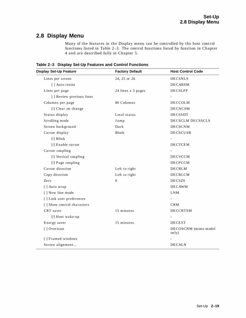
Set-Up2.8 Display Menu
2.8 Display MenuMany of the features in the Display menu can be controlled by the host controlfunctions listed in Table 2–3. The control functions listed by function in Chapter4 and are described fully in Chapter 5.
Table 2–3 Display Set-Up Features and Control Functions
Display Set-Up Feature Factory Default Host Control Code
Lines per screen 24, 25 or 26 DECSNLS
[ ] Auto resize DECARSM
Lines per page 24 lines x 3 pages DECSLPP
[ ] Review previous lines -
Columns per page 80 Columns DECCOLM
[/] Clear on change DECNCSM
Status display Local status DECSSDT
Scrolling mode Jump DECSCLM DECSSCLS
Screen background Dark DECSCNM
Cursor display Block DECSCUSR
[/] Blink -
[/] Enable cursor DECTCEM
Cursor coupling -
[/] Vertical coupling DECVCCM
[/] Page coupling DECPCCM
Cursor direction Left to right DECRLM
Copy direction Left to right DECRLCM
Zero 0 DECSZS
[ ] Auto wrap DECAWM
[ ] New line mode LNM
[ ] Lock user preferences -
[ ] Show control characters CRM
CRT saver 15 minutes DECCRTSM
[/] Host wake-up -
Energy saver 15 minutes DECEST
[ ] Overscan DECOSCNM (mono modelonly)
[ ] Framed windows -
Screen alignment... DECALN
Set-Up 2–19

Set-Up2.8 Display Menu
2.8.1 Lines per ScreenThis menu chooses a font that enables the selected number of lines to be viewed.Note that you cannot view more lines than the number of lines on a page (Linesper page).
If the Status display is enabled, it is displayed using one of the same Lines perscreen as the text for the corresponding session.
This is an operator preference feature and cannot be changed by control functionsif the operator preference is set to Lock user preferences; however, if Autoresize is enabled at the same time, then the number of Lines per screenchanges when the page size changes.
This feature can be changed from the host using the DECSNLS control function.Or, it may be changed indirectly from the host if Auto resize is selected and thepage configuration is changed using DECSLPP.
2.8.1.1 Auto ResizeWhen Auto resize is enabled, the number of lines per screen changesautomatically each time the page arrangement changes, either by the host orthrough Set-Up. Table 2–4 shows how the screen size changes whenever the pagesize changes when Auto Resize is set.
Table 2–4 Lines per Page vs. Lines per Screen When Auto Resize is Set
Lines per Page Lines per Screen
24 26
25 26
36 43
42 43
43 43
48 52
52 52
72 52
If Auto resize is enabled in Display Set-Up, switching to two windows will setlines per screen to 48 and switching to one window will set lines per screen tocorrespond with the most recent lines per page setting, as if DECSLPP had beenreceived. This applies to all sessions with auto-resize enabled.
2.8.2 Lines per PageThis menu allows you to select the page size in lines and number of pages.The page size determines the addressing range for cursor positioning and scrollregions. The number of lines that can be displayed depends on the current settingof the Lines per screen feature.
Lines per page sizes not available based on the current page memory allocationare dimmed. If the page memory allocation is changed such that the currentlyselected number of lines per page is not available, the factory default page size isused (24 lines per page for the VT emulations).
2–20 Set-Up
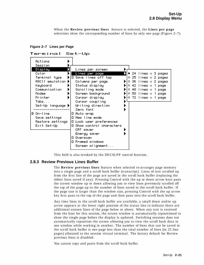
Set-Up2.8 Display Menu
When the Review previous lines feature is selected, the Lines per pageselections show the corresponding number of lines by only one page (Figure 2–7).
Figure 2–7 Lines per Page
This field is also invoked by the DECSLPP control function.
2.8.3 Review Previous Lines BufferThe Review previous lines feature when selected re-arranges page memoryinto a single page and a scroll back buffer (transcript). Lines of text scrolled upfrom the first line of the page are saved in the scroll back buffer (replacing theoldest lines saved if any). Pressing Control with the up or down arrow keys pansthe screen window up or down allowing you to view lines previously scrolled offthe top of the page up to the number of lines saved in the scroll back buffer. Ifthe page size is larger than the window size, pressing Control with the up arrowkey first pans to the top of the page and then pans into the scroll back buffer.
Any time lines in the scroll back buffer are available, a small down and/or uparrow appears at the lower right position of the status line to indicate there areadditional unseen lines of the page below or above. When any text is receivedfrom the host for this session, the screen window is automatically repositioned toshow the single page before the display is updated. Switching sessions does notautomatically reposition the screen allowing you to view the scroll back data inone window while working in another. The number of lines that can be saved inthe scroll back buffer is one page less than the total number of lines (in 25 linepages) allocated to the session virtual terminal. The factory default for Reviewprevious lines is disabled.
You cannot copy and paste from the scroll back buffer.
Set-Up 2–21

Set-Up2.8 Display Menu
2.8.4 Columns per Page, Clear on ChangeThis menu allows you to select an 80- or 132-column display for text. If Clearon change is disabled, changing this feature does not clear page memory, exceptwhen changing from 132 columns to 80 columns; then, columns 81 through 132 ofeach page are cleared. Changes to this field take effect immediately.
This field is also invoked by the DECSCPP and DECCOLM control functions.The Clear on change feature affects the behavior of the DECCOLM sequenceor 80/132 column mode setting only. It does not erase page memory. The factorydefault is "clear on change" for backward compatibility with previous terminals.
2.8.5 Status DisplayThe Status display can be enabled in the following selections:
� Local status
� Host writable or editing
� None
2.8.6 Scrolling ModeThe Scrolling mode menu allows you to select how fast lines appear on thescreen.
Scroll Selection Scroll Rate
Slow smooth Smooth steady scroll at approximately 9 lines per second(two scan lines per frame time).
Fast smooth Smooth scrolls at approximately 18 lines per second.
Jump Displays new lines as fast as they are received, causing a jumpscroll on the screen.
This is a user-preference feature. If Lock user preferences is set, then thisfield is not invoked by any control functions.
2.8.7 Screen BackgroundThe Screen background can be either dark or light, with dark as the default.
2.8.8 Cursor DisplayThe Cursor display can be enabled in the following selections:
� Block
� Underline
/ Blink
/ Enable cursor
2.8.9 Cursor CouplingCursor coupling can be Vertical and/or Page coupling selectable from a singlesubmenu.
2–22 Set-Up

Set-Up2.8 Display Menu
Vertical CouplingVertical coupling selects whether the user window automatically pans to followthe cursor when the cursor is moved vertically to a part of the page that is notin the currently displayed user window. Panning does not occur until the inputbuffer becomes empty and the cursor is displayed.
When Vertical coupling is disabled, the user window does not follow the cursor.If the cursor moves above or below the visible portion of the page, the cursor is nolonger visible.
Page CouplingPage coupling selects whether the user window automatically follows the cursorwhen the cursor is moved to a page that is not currently in the user window.When page coupling is enabled, moving the cursor to a page that is not currentlydisplayed causes that page to be displayed. Panning does not occur until theinput buffer becomes empty and the cursor is displayed.
When Page coupling is disabled, the user window does not follow the cursor. Ifthe cursor moves to a page that is not currently displayed, the cursor is no longervisible.
2.8.10 Writing DirectionThe Writing direction and copy direction defaults are left to right. If a Hebrewkeyboard is connected to the terminal, a selection is available for advancing orcopying right to left.
The writing direction and the copy direction should be matched.
2.8.11 ZeroA Zero feature allows you to select the style of the zero character: oval, zero witha slash, or zero with a dot.
2.8.12 Auto WrapAuto wrap selects where a received character is displayed when the cursor is atthe right margin.
This is not a user-preference feature, so you cannot lock this feature.
This field can be invoked by the DECAWM control function. The Auto wrapsetting can be saved in NVM.
2.8.13 New Line ModeWhen enabled, New line mode selects the characters transmitted by Return,CR, or CR+LF. It also determines the action taken by the terminal when receivingline feed, form feed, and vertical tab, LF, or CR+LF.
New line mode is not a user-preference feature, so you cannot lock it. Thisfeature can be invoked by the DECNLM (SM/RM) control function.
2.8.14 Lock User PreferencesThe Lock user preferences feature allows you to prevent the host frommodifying user-preference features. If set to lock, the user-preference featurescannot be changed by host control functions.
The following user-preference features are locked and unlocked by this featureand when locked, cannot be changed by control functions:
• Auto repeat
Set-Up 2–23
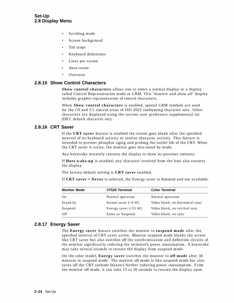
Set-Up2.8 Display Menu
• Scrolling mode
• Screen background
• Tab stops
• Keyboard definitions
• Lines per screen
• Auto resize
• Overscan
2.8.15 Show Control CharactersShow control characters allows you to select a normal display or a displaycalled Control Representation mode or CRM. This "monitor and show all" displayincludes graphic representation of control characters,
When Show control characters is enabled, special CRM symbols are usedfor the C0 and C1 control areas of ISO 2022 conforming character sets. Othercharacters are displayed using the current user preference supplemental set(DEC default character set).
2.8.16 CRT SaverIf the CRT saver feature is enabled the screen goes blank after the specifiedinterval of no keyboard activity or receive character activity. This feature isintended to prevent phosphor aging and prolong the useful life of the CRT. Whenthe CRT saver is active, the monitor goes into stand by mode.
Any keystroke instantly restores the display to show its previous contents.
If Host wake-up is enabled, any character received from the host also restoresthe display.
The factory default setting is CRT saver enabled.
If CRT saver = Never is selected, the Energy saver is dimmed and not available.
Monitor Mode VT520 Terminal Color Terminal
On Normal operation Normal operation
Stand by Screen saver (~4 W) Video blank, no horizontal sync
Suspend Energy saver (<15 W) Video blank, no vertical sync
Off Same as Suspend Video blank, no sync
2.8.17 Energy SaverThe Energy saver feature switches the monitor to suspend mode after thespecified interval of CRT saver active. Monitor suspend mode blanks the screenlike CRT saver but also switches off the synchronization and deflection circuits ofthe monitor significantly reducing the terminal’s power consumption. A keystrokemay take several seconds to restore the display from suspend mode.
On the color model, Energy saver switches the monitor to off mode after 30minutes in suspend mode. The monitor off mode is like suspend mode but alsoturns off the CRT cathode (heater) further reducing power consumption. Fromthe monitor off mode, it can take 15 to 30 seconds to restore the display upon
2–24 Set-Up

Set-Up2.8 Display Menu
detecting a keystroke. The color model follows the VESA convention for drivingEnergy Star1 compliant PC monitors.
Received characters power the monitor back on from the Energy saver suspendor monitor off state only if CRT Saver Host wake-up is selected. Otherwise it isnecessary to press a key to power the monitor back on.
2.8.17.1 Warning BellThe terminal’s warning bell still operates normally in all energy saver states.Many host systems ring the warning bell to indicate new mail has arrived or todraw attention to an important system message. Upon hearing the bell, pressany key to see the corresponding host message.
Energy saver = Never allows power to continue to be supplied to the monitor.
2.8.18 OverscanOverscan can be enabled for the monochrome VT520. It is dimmed and notavailable for the color model.
2.8.19 Framed WindowsWhen the Framed windows check box is selected in the Display menu, windowframes with title bars are added to each displayed window. The VT520 has a flipscreen and a two-window style with adjustable split. Window frames with titlesand icons help you keep track of up to four sessions.
On the mono VT520, the Framed windows check box controls whether sessionwindows are displayed with title bars and session icons.
802 � 480 no overscan, or800 � 432 with optional overscan.
When Framed windows is selected, the overscan check box is dimmed. Framedwindows is the factory default.
On the color terminal, only the 802 x 480 no overscan format is available. TheFramed windows check box controls whether session windows are displayed withtitle bars and session icons (802 x 480 no overscan), or the window frame and iconscan lines are left blank. There is no overscan selection on the color terminal.
When the Framed windows check box is selected in the Display menu, windowframes with title bars are added to each displayed window. The title bar showsthe previously entered session name if any and is highlighted (filled in) when thesession is active. A row of icons is presented across the top of the screen to helpyou to keep track of the other sessions.
An icon is displayed for each session in the cycle order followed by the icon namewhich consists of the first 12 characters of the session name unless overwrittenby host control function. The icon for the active session is displayed with thereverse video attribute. If the page memory of a session that is not currentlyvisible is updated so that it contains new data which has not yet been seen, thecorresponding session icon is displayed with the blink video attribute until thesession is made active.
1 The Energy Star emblem does not represent EPA endorsement of any product or service.
Set-Up 2–25
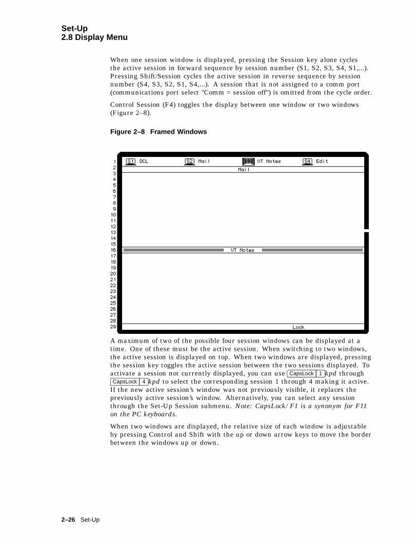
Set-Up2.8 Display Menu
When one session window is displayed, pressing the Session key alone cyclesthe active session in forward sequence by session number (S1, S2, S3, S4, S1,...).Pressing Shift/Session cycles the active session in reverse sequence by sessionnumber (S4, S3, S2, S1, S4,...). A session that is not assigned to a comm port(communications port select "Comm = session off") is omitted from the cycle order.
Control Session (F4) toggles the display between one window or two windows(Figure 2–8).
Figure 2–8 Framed Windows
A maximum of two of the possible four session windows can be displayed at atime. One of these must be the active session. When switching to two windows,the active session is displayed on top. When two windows are displayed, pressingthe session key toggles the active session between the two sessions displayed. Toactivate a session not currently displayed, you can use CapsLock 1 kpd throughCapsLock 4 kpd to select the corresponding session 1 through 4 making it active.
If the new active session’s window was not previously visible, it replaces thepreviously active session’s window. Alternatively, you can select any sessionthrough the Set-Up Session submenu. Note: CapsLock/F1 is a synonym for F11on the PC keyboards.
When two windows are displayed, the relative size of each window is adjustableby pressing Control and Shift with the up or down arrow keys to move the borderbetween the windows up or down.
2–26 Set-Up
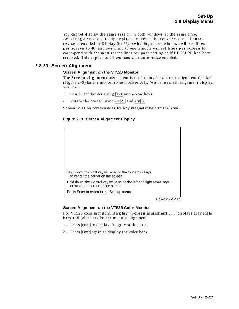
Set-Up2.8 Display Menu
You cannot display the same session in both windows at the same time.Activating a session already displayed makes it the active session. If auto-resize is enabled in Display Set-Up, switching to two windows will set linesper screen to 48, and switching to one window will set lines per screen tocorrespond with the most recent lines per page setting as if DECSLPP had beenreceived. This applies to all sessions with auto-resize enabled.
2.8.20 Screen AlignmentScreen Alignment on the VT520 MonitorThe Screen alignment menu item is used to invoke a screen alignment display(Figure 2–9) for the monochrome monitor only. With the screen alignment display,you can:
• Center the border using Shift and arrow keys.
• Rotate the border using Ctrl( and Ctrl) .
Screen rotation compensates for any magnetic field in the area.
Figure 2–9 Screen Alignment Display
Hold down the Shift key while using the four arrow keysto center the border on the screen.
Hold down the Control key while using the left and right arrow keysto rotate the border on the screen.
Press Enter to return to the Set−Up menu.
MA−0022−93.GRA
Screen Alignment on the VT525 Color MonitorFor VT525 color monitors, Display . screen alignment . . . displays gray scalebars and color bars for the monitor alignment.
1. Press Enter to display the gray scale bars.
2. Press Enter again to display the color bars.
Set-Up 2–27

Set-Up2.9 Color Set-Up
2.9 Color Set-UpThe Color Set-Up allows you to control the use of color by the terminal.
The ASCII color mode, Reverse and blank attributes, and Intensityattributes are only available in ASCII terminal emulation modes.
Select color mode is only available in the non-ASCII terminal emulation modesbesides SCO Console mode which always uses ANSI SGR color.
Alternate text colors... is only available when Select color mode = Alternatecolor.
Figure 2–10 Color Set-Up Menu
2.9.1 Assign ColorsThe Assign colors dialog box allows you to select normal display colors for textand windowing features. As the slider moves to select a color within the selectcolor box, the corresponding item is displayed using that color. Changing thenormal text background only re-writes the "Normal text" caption. It does nototherwise affect the color of text already displayed.
2–28 Set-Up

Set-Up2.9 Color Set-Up
Figure 2–11 Assign Colors
The normal text background and foreground selections determine the writingcolor used when all SGR attributes are turned off. The other ANSI colorSGR attributes are "hard wired" to corresponding color indexes. Each sessionmaintains its own color assignments for normal text and other data within itswindow.
The window frame colors are global affecting all session windows and icons. Thewindow frame includes the title bar and adjacent separator lines, the sides, andthe bottom separator line.
The session icons and keyboard indicator line foreground are displayed using theWindow frame foreground color (or background color when dark text on a lightbackground is selected). The icon and keyboard indicator line background usesthe screen background color to merge with the screen border rather than thewindow title bar.
New color assignments do not take affect until you press OK. Color assignmentscan be saved in NVM or restored to their factory defaults the same as otherSet-Up features.
It is possible to assign text foreground and background colors that makesubsequent text difficult to read. Set-Up is displayed using the factory defaultcolors with the exception of those dialog boxes that affect color selections. Thisensures that Set-Up is always usable.
Set-Up 2–29
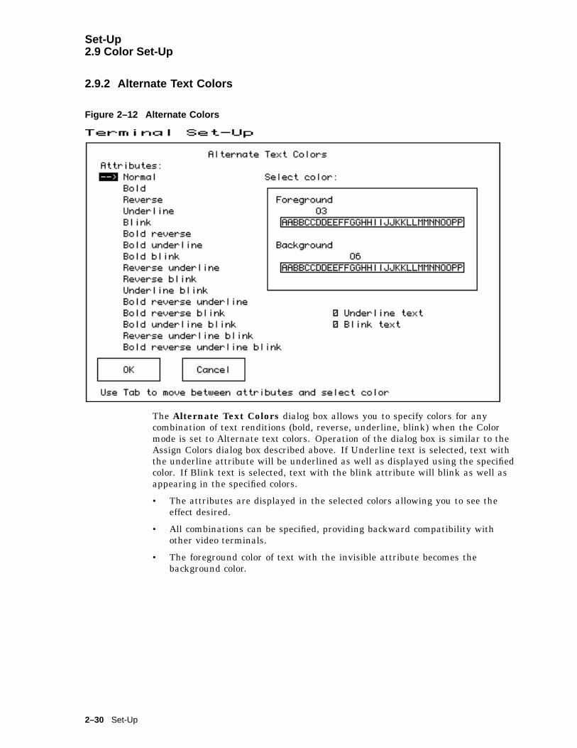
Set-Up2.9 Color Set-Up
2.9.2 Alternate Text Colors
Figure 2–12 Alternate Colors
The Alternate Text Colors dialog box allows you to specify colors for anycombination of text renditions (bold, reverse, underline, blink) when the Colormode is set to Alternate text colors. Operation of the dialog box is similar to theAssign Colors dialog box described above. If Underline text is selected, text withthe underline attribute will be underlined as well as displayed using the specifiedcolor. If Blink text is selected, text with the blink attribute will blink as well asappearing in the specified colors.
• The attributes are displayed in the selected colors allowing you to see theeffect desired.
• All combinations can be specified, providing backward compatibility withother video terminals.
• The foreground color of text with the invisible attribute becomes thebackground color.
2–30 Set-Up

Set-Up2.9 Color Set-Up
2.9.3 Define Colors Dialog Box
Figure 2–13 Define Colors
The Define colors dialog box allows you to define the terminal’s color map with16 colors from a palette of 4096 colors. This dialog box is intended for adjustingthe appearance of individual colors. Radical changes to the terminal’s color mapmay adversely affect the appearance of ANSI color SGR parameters. In theVT520, each session uses its own independent color map which is not affected bythe others.
The boxed areas containing capital letters A-P represent the 16 colors currentlydefined. The selected color number (0-15) remains highlighted in reverse videowhile the highlighting cursor moves to the RGB sliders and then down to thelabeled buttons.
Color definition changes become visible immediately since the terminal has asingle active color map. Cancel restores the color map to the settings in effectwhen the OK or Save button was last pressed. The OK and Cancel buttonsexit this dialog box. Pressing Save is similar to pressing OK but also writes thesettings to NVM to be used as the power-on settings. Restore recalls the power-onsettings from NVM. Use default recalls the factory default settings.
It is possible to define colors that make subsequent text difficult to read. Set-Upis displayed using the factory default colors with the exception of those dialogboxes that affect color selections. This ensures that Set-Up is always usable.
Set-Up 2–31
Set-Up2.9 Color Set-Up
2.9.4 Select Color ModeThe Select color mode feature allows you to select how applications will displaytext colors.
• When ANSI SGR color is selected, color text is specified using the ANSIdefined SGR color parameters. The terminal uses factory default renditionsfor text attributes as defined in Table 2–5.
• When Alternate color is selected, the terminal displays text renditions asdefined in the Alternate Text Colors dialog box.
• When Mono is selected, the terminal uses a default monochrome or graylevel map designed to maintain the appearance of applications that were notdesigned to use color.
Table 2–5 Default Graphic Renditions
Graphic Rendition Factory Default Display
Normal text background Color index 0
Normal text foreground Color index 7
Bold text foreground Color index + 8
Bold text background Color index (unchanged)
Reverse text Write text foreground with background color andbackground with foreground color.
The Color selection maintains a current graphic rendition that includes a textbackground color and text foreground color. Reverse text does not exchangethe foreground and background colors stored as part of the graphic rendition,rather, it causes the text foreground to be written with the background color andvice versa. Specifying a new foreground color always modifies the "foregroundrendition." Subsequent text written with the Reverse attribute will write thiscolor as its background.
2.9.5 ASCII Color ModeThe ASCII color mode determines the use of color in the ASCII terminalemulation modes. Color emulates WYSE 325 color. Mono uses a defaultmonochrome or gray level map designed to maintain the appearance of ASCIIterminals using applications that were not designed to use color.
2.9.6 Bold and Blink StyleBold and blink style selects whether the bold and blink attributes bold andblink the text foreground only, or both foreground and background. By default,bold adds 8 to the corresponding color index value to select a brighter or dimmercolor, and blink cycles the text color between its non-blink rendition and a dimmerless saturated shade of the non-blink rendition.
2.9.7 Erase ColorThe Erase color selection controls the background color used when text is erasedor new text is scrolled on to the screen. Screen background causes newlyerased areas or scrolled text to be written using color index zero, the screenbackground. This is VT and DECterm compatible. Text background causeserased areas or scrolled text to be written using the current text backgroundcolor. This is PC console compatible and is the factory default.
2–32 Set-Up
Set-Up2.9 Color Set-Up
2.9.8 Reverse and Blank AttributesThe Reverse and blank attributes selection controls whether the reverse orblank text attributes are mapped to different colors in WYSE 325 emulation.
When Map reverse attribute is selected:
1. The characters with reverse attribute are displayed by the color which isassigned to the REVERSE/BLANK map in the color palette.
2. The characters with blank attribute are displayed by the color which isassigned to the NORMAL map in the color palette.
When Map blank attribute is selected:
1. The characters with reverse attribute are displayed by exchanging theforeground and background of the NORMAL map in the color palette.
2. The characters with blank attribute are invisible; that is, the foreground fallsback to the background of the REVERSE/BLANK map in the color palette.
2.9.9 Intensity AttributesThe Intensity attributes check box operates in WYSE 325 color mode.When Enabled:
1. The characters with dim attribute are displayed in a lower intensity.
2. The characters without dim attribute, but were written in intensity disabledmode are displayed in a lower intensity when intensity mode is changed toenable.
When Disabled:All characters are displayed with their normal intensity.
2.10 Terminal Type MenuYou can select terminal type and emulation modes using this menu.
2.10.1 Emulation ModeEmulation mode is the primary means of selecting different terminal modesor emulations. Changing terminal modes or emulations usually performs someinitialization of the terminal state.
Changes to the terminal emulation mode take effect immediately (as soon theemulation mode submenu is exited). Other Set-Up parameters are updatedaccordingly based on the new emulation mode without exiting Set-Up.
Example: Selecting a VT mode performs a soft terminal reset (DECSTR).
PCTerm mode can be selected or deselected independently from the otheremulations. The ASCII modes use WYSE PCTerm. The ANSI modes use VTPCTerm. The ASCII color mode uses WYSE 325 emulation.
This feature corresponds to the DECPCTERM, DECTME, DECANM, andDECSCL control functions described in Chapter 5.
Changing the conformance level (DECSCL) does not change the operating levelreported to identify the terminal to the host. It only changes the way extensionsare reported.
Set-Up 2–33
Set-Up2.10 Terminal Type Menu
Notes
• Printer operations are not affected or halted by a change in mode.
• A soft reset is always performed as a result of a mode change fromSet-Up.
• Changes resulting from most, but not all, of the above sequences alsocause a soft reset. Exception: Entering VT52 mode (via DECANM)does not cause a soft reset from VT100 mode, but does cause a softreset from VT500 mode.
2.10.2 Terminal ID to HostTerminal ID to host selects how the terminal identifies itself to host software,specifically the Primary Device Attributes response (DA). The default ID is"VT520."
For a list of the responses, see the Device Attributes sections in Chapter 5. Thisfield has no effect when the terminal is in VT52 mode. The feature correspondsto the DECTID control function described in Chapter 5.
2.10.3 VT Default Character SetThis feature selects the default international character set to use for output asinitialized in G0-G3 and GL/GR. It corresponds to the DECAUPSS (Assign UserPreference Supplemental Set) control function described in Chapter 5.
Only ISO Latin-1 and DEC Multinational are available on the North Americanterminal.
2.10.4 PCTerm Character SetThis feature selects the PC code page, ISO character set, or DEC character set tobe used in PCTerm mode and SCO Console mode. This feature is also invoked bythe DECPCTERM control function described in Chapter 5.
2.10.5 7-Bit NRCS CharactersThis feature enables National Replacement Character Set mode (DECNRCM),as described in Chapter 5. When 7-bit NRCS characters are selected, acorresponding 7-bit NRC set is used depending on the keyboard language. SeeChapter 8 for details. Group 2 or secondary keyboard language characters maystill be used if they are in the 7-bit character set. This feature is dimmed unlessthere is a corresponding NRC set available. This feature is not available on theNorth American terminal.
2.10.6 Transmit 7-Bit ControlsTransmit 7-bit controls selects whether C1 control codes are sent in theiroriginal 8-bit form (disabled) or converted to their 7-bit ESC Fe form.
This field is invoked by a parameter to the DECSCL control function and by theS7C1T and S8C1T control functions.
2–34 Set-Up

Set-Up2.11 ASCII Emulation Menu
2.11 ASCII Emulation Menu
Figure 2–14 ASCII Emulation Menu
The features, shown in Figure 2–14 and listed in Table 2–6, are specific tothe ASCII emulation modes supported in the VT520. The default is shown inboldface type. Refer to Part III for details.
Table 2–6 ASCII Emulation Features
Feature Selections Determine...
Data lines 24, 25, 42, 43lines
The number of data display lines visible, notcounting any status lines.
Pages 1 � lines2 � lines4 � lines*
The page size and number of pages. 1 � linesselects each page to be the number of data linesvisible on the screen. The * makes the display of asingle page invisible.
Attribute Character,line, or page
How visual attributes are applied per character,line, or page.
Write protectattributes
Dim, blank,reverse,underline,and/or blink.
The visual attributes used to highlight and specifywrite protected data.
Received CR CR or CRLF Carriage return or carriage return line feed.
Block Mode Conversationor Block
Transfer method.
Block End US/CR orCRLF/ETX
At the end of a block transfer, transmit a carriagereturn or an end-of-text character.
Set-Up 2–35

Set-Up2.12 Keyboard Menu
2.12 Keyboard Menu
Figure 2–15 Keyboard Menu
Several of the features shown in Figure 2–15 are self-explanatory and corresponddirectly to control functions listed in Table 2–7. For additional information, seeChapters 4 and 5.
Table 2–7 Keyboard Features and Control Functions
Set-Up Feature Control Function
Keyboard language DECKBD
Switch between primary andsecondary keyboard language
DECESKM (general), DECHEBM (Hebrew),DECNAKB (Greek), DECCYRM (Cyrillic)
Caps lock function DECLCK
Keyclick volume DECKCV
Warning bell volume DECWBV
Margin bell volume DECMBV
Keyboard encoding DECKPM
Auto repeat DECARM
Data processing keys DECKBUM
Application cursor keys DECCKM
Application keypad mode DECKPNM, DECKPAM, DECNKM
2–36 Set-Up

Set-Up2.12 Keyboard Menu
2.12.1 Keyboard LanguageSome keyboards allow you to select two different keyboard layouts and easilyswitch between them (English and Hebrew, for example). This feature allowsthe VT520 to support both existing conventions and emerging standards forextending the graphic input and/or switching between languages in dual languageenvironments. (The North American keyboard has only one keyboard language,English.)
The primary keyboard language corresponds to Group 1 (per DIN 2137) andgenerally references the legends on the left half of the keytops.
The secondary keyboard language corresponds to Group 2 (Group Shift per DIN2137) and generally references the legends on the right half of the keytops.
Unless overridden, Ctrl/Alt/F1 makes the primary keyboard language active, andCtrl/Alt/F2 makes the secondary keyboard language active. (These are factory
defaults, standard on PCs.)
Selecting a new keyboard language in Set-Up automatically initializes thekeyboard character set, as described in Chapter 8.
Changes to this field take effect immediately. Changing this field to NorthAmerican or Dutch and then exiting Set-Up or going to another menu resets the7-bit NRCS characters feature to disabled. There is no "7-bit characters" modefor the North American or Dutch keyboards. This field affects the language of thekeyboard indicator line.
2.12.2 Define Key EditorThe Define Key Editor is an advanced function that allows the terminal to adaptto environments that do not match the preprogrammed settings.
Caution
This function is designed to be easy to use; however, unless youunderstand the consequences of remapping various key combinations,use caution when using this feature.
The Define key menu invokes the Define Key Editor.
To ensure consistent access to Set-Up features, the following rules apply forinterpreting keystrokes.
• Within Set-Up and the Define Key Editor, the four arrow keys along withEnter , Return , Do , Select and delete key <x are interpreted according to theirstandard definitions, regardless of how they may be redefined at other times.The delete key will erase a field when defining an alphanumeric key. The oneexception is when pressing the key to be defined.
• When you press F3 as the first key after the terminal is powered on, youalways enter Set-Up, regardless of which keyboard you use or how F3 isdefined.
• When copying one key definition to another, the standard key definition fora key is copied, not the current definition. This copy method ensures thatkeyboard functions are not lost within the Define Key Editor.
Set-Up 2–37
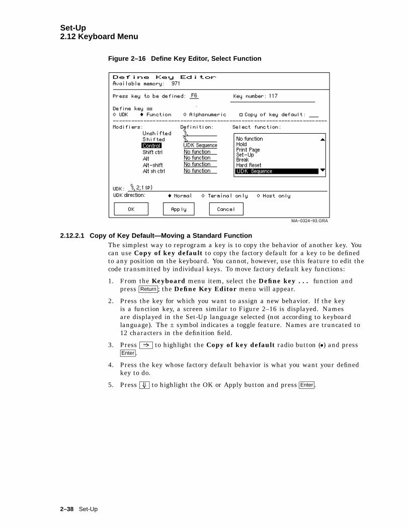
Set-Up2.12 Keyboard Menu
Figure 2–16 Define Key Editor, Select Function
MA−0324−93.GRA
2.12.2.1 Copy of Key Default—Moving a Standard FunctionThe simplest way to reprogram a key is to copy the behavior of another key. Youcan use Copy of key default to copy the factory default for a key to be definedto any position on the keyboard. You cannot, however, use this feature to edit thecode transmitted by individual keys. To move factory default key functions:
1. From the Keyboard menu item, select the Define key . . . function andpress Return ; the Define Key Editor menu will appear.
2. Press the key for which you want to assign a new behavior. If the keyis a function key, a screen similar to Figure 2–16 is displayed. Namesare displayed in the Set-Up language selected (not according to keyboardlanguage). The ± symbol indicates a toggle feature. Names are truncated to12 characters in the definition field.
3. Press ) to highlight the Copy of key default radio button (�) and pressEnter .
4. Press the key whose factory default behavior is what you want your definedkey to do.
5. Press + to highlight the OK or Apply button and press Enter .
2–38 Set-Up

Set-Up2.12 Keyboard Menu
2.12.2.2 CustomizationIf you want to program a key to behave differently than one of the factory definedkeys, then you will need to know about the following key categories:
Function: Keys such as the arrow keys (*, +, (, )), the Shift modifier key, or theSet-Up key, used to transmit function key sequences or to perform localterminal functions.
Alphanumeric: Keys used to transmit alphanumeric characters.
2.12.2.3 Modifier KeysModifier keys vary from within the Function and Alphanumeric categories. Amodifier key is a key that modifies the behavior of other keys when it is pressedand held down. For example, pressing an alphanumeric key in combination withthe Shift modifier key will normally send the shifted or uppercase characters forthat key.
Modifier keys are treated as a special kind of local terminal function. The VT520function modifier keys are: Shift , Ctrl , and Alt . VT520 alphanumeric keys can alsobe modified by pressing Group Shift ( Alt Gr on enhanced PC keyboards) and Alt/Shift
(Shift-2). Modifier keys themselves cannot normally be modified by other keys. Akey assigned to act as the Shift modifier, for example, cannot transmit a functionsequence when pressed in combination with Alt . Defining a key as a modifier keymakes all assignable combinations of that key act as a modifier.
2.12.2.4 Creating a New FunctionTo define a new function key:
1. From the Keyboard menu item, select the Define key . . . function andpress Return ; the Define Key Editor menu will appear.
2. Press the key for which you want to assign a new behavior.
3. Press the ( or ) key to highlight the Function radio button (�) andpress Enter .
4. Press the * and + keys to highlight the modifier combination that youwant to define (Unshifted, Shifted, Control, and so on) and press Enter .
5. Press the ) key to move to the Select function scroll box. Press the *
and + keys to highlight the desired keystroke function from the list andpress Enter .
6. Press the ( key to return to the Modifiers.
7. Repeat steps 4 through 6 to define other modifier combinations as desired.
8. Use the arrow keys (*, +, (, )) to highlight the OK or Apply button andpress Enter .
2.12.2.5 Examples of Creating New FunctionsExamples of when to create new functions include:
• Changing the <x or Delete key to delete when unshifted and to backspacewhen shifted.
• Disabling the Compose , Break , and Set-Up keys by assigning them to have nofunction.
Set-Up 2–39

Set-Up2.12 Keyboard Menu
2.12.2.6 Correcting a MistakeIf you make a mistake or want to start over, choose the Cancel button. UseActions . Restore factory defaults to restore the factory default settings.
2.12.2.7 Creating A New Alphanumeric Key or Keyboard LayoutThe method for creating a new alphanumeric key is similar to that for functionkeys, except that you can define different modifier combinations and you enteralphanumeric values differently.
If the key was previously programmed as a function key, the function definitionwill be empty. Once any function definition is applied, all the alphanumericdefinitions for that key are lost. A single key cannot act as both a function keyand an alphanumeric key simultaneously.
To define a new alphanumeric key:
1. From the Keyboard menu item, select the Define key . . . function andpress Return ; the Define Key Editor menu will appear.
2. Press the key for which you want to assign a new behavior.
3. Press the ( or ) key to highlight the Alphanumeric radio button (�)and press Enter . The character transmitted when this key is unshifted ishighlighted.
4. To select a different character, press the corresponding key on the keyboard,or use the numeric compose key to generate a new character.
5. If desired, press the ) key to move to the Non-spacing accent scroll box.Press the * and + keys to highlight any non-spacing accent from the listand press Enter .
6. The code transmitted by the unshifted alphanumeric key when pressed incombination with the Control key is calculated automatically and displayed inthe Definition column. If desired, you may redefine this function.
7. If desired, select an Alt Function modifier combination for the alphanumerickey from the Select Function scroll box. You may choose a function,including a user-defined key (UDK) sequence. The default for the AltFunction is None.
8. Press the ( key to return to the modifier selection.
9. Use the arrow keys (*, +, (, )) to highlight the OK or Apply button andpress Enter .
To enter alphanumeric values you can type the desired character or numeral, youcan compose the desired character including numeric keypad compose, or you canselect a nonspacing accent from the nonspacing accent scroll box.
2.12.2.8 Examples of Creating New Alphanumeric KeysExamples of when to create new alphanumeric keys include:
• Making the comma and period keys send comma and period instead of anglebrackets when shifted.
• Changing the keyboard from a QWERTY to QWERTZ layout.
• Defining an alternate key layout to match your own preference or local typingconventions (Dvorak, or Russian Cyrillic, instead of Bulgarian Cyrillic).
2–40 Set-Up

Set-Up2.12 Keyboard Menu
2.12.2.9 User-Defined KeysThe UDK radio button allows any key to be programmed with a user-definedsequence. UDKs are a subset of function keys. A separate UDK dialog box isprovided for simplicity. Selecting UDK causes a UDK: text field to be displayedso you can enter a key sequence. This text field can scroll left or right as neededto allow longer strings to be entered.
Enter control codes by holding the Compose or Alt key down and entering thedecimal value for the code on the Numeric keypad. Codes may also be entered onthe Numeric keypad in column/row format as follows:
Compose 1 . 1 1
Press + again to move the highlighting cursor to select one of the followingUDK directions:
� Normal The sequence is sent to the host and/or to the screen depending onthe communication settings (On-line, Local echo, Half duplex, and soon).
� Terminal only The sequence is sent only to the screen, as if it had just beenreceived from the host.
� Host only The sequence is sent only to the host, regardless of thecommunication settings.
Press + again to select one of the following buttons:
OK Apply Cancel
When you select Cancel, you only cancel the changes to the currently selectedmodifier combination.
2.12.2.10 Programming Notes
• When you press F3 as the first key after the terminal is powered on, youalways enter Set-Up, regardless of how F3 is defined.
• The factory default Break function (unshifted F5) cannot be reprogrammed byhost control sequence. This is necessary to support secure attention. If thesequence is received, the factory default keystroke table entry for Break is notoverwritten.
• If a key is programmed to act as a modifier key, it operates as a modifier withany combination of Shift , Alt , or Control .
• If a key is programmed to be a modifier key and modifier key reporting isenabled using DECSMKR, the key sends the VT sequence for the left modifierkey when there is more than one.
• Caps Lock combinations such as Caps Lock/Print Screen are local keyboardextensions and cannot be reprogrammed by DECPFK. The Caps Lock key actsas a modifier. The Caps Lock function can be moved to another key, but Pause
must still send the Break.
• Use of the Define Key Editor to redefine keys on the numeric keypad affectsonly the Num Lock off state of these keys. When Num Lock is engaged, thesekeys will always send their factory default ASCII numerals (and relatedcharacters) intended for numeric input. The Num Lock behavior of thesekeys cannot be reprogrammed. (This Num Lock behavior does not apply tonumeric keypad mode on the VT keyboard or PC keyboard in VT style.)
Set-Up 2–41

Set-Up2.12 Keyboard Menu
• The toggle Num Lock function can be assigned to any single key combination.Although the Num Lock state modifies other keys, the toggle Num Lockfunction is not a modifier key. This means modifier combinations of
Num Lock/Key can be assigned to any other function or user-defined sequence.
• Use of the numeric keypad to compose characters by entering their decimalcode in combination with Alt Gr or Compose (held down) should continue towork regardless of any reprogramming of keys on the numeric keypad, unlesssuch reprogramming directly conflicts with use of the keypad in this manner.Example: A numeric keypad key has been defined as Compose or Alt Gr .
• Function keys also work in VT100 mode.
2.12.3 Save Key DefinitionsTo save your key definitions so they will be available the next time you turn thepower on, select the Save key definitions menu item from the Keyboard menu.
This action field on the keyboard menu (Figure 2–15) causes the Define keymodifications to be saved to nonvolatile memory independently from any otherSet-Up features. Key definitions are saved on a first-come first-served basis andare limited by the total amount of nonvolatile memory available.
This feature cannot be invoked by a host control function.
2.12.4 Recall Key DefinitionsThis action field causes previously saved Define key modifications to be recalledfrom nonvolatile memory independently from any other Set-Up features.
2.12.5 Lock Key DefinitionsThe Lock key definitions menu item operates as a check box. When keydefinitions are locked, they cannot be reprogrammed from the host.
2.12.6 Caps Lock FunctionThis function allows you to enable the Lock or Caps Lock key to do the following:
� Caps lock Lock alpha keys on main keypad in uppercase setting.
� Shift lock Lock alpha and numeric keys on main keypad in shifted setting.
� Reverse lock Works the same as Caps Lock, except that pressing the Shift keywill send the lowercase or unshifted character assigned to a key.
2.12.7 Keyclick, Warning Bell, and Margin Bell VolumeThe volume of these settings can be set to high, low, or off, with high as thedefault.
Suppress repeated warnings causes the terminal to ignore Control-G warningbells encountered within two seconds of a previously sounded warning bell. Whenusing multiple sessions, this feature prevents broadcast messages sent to morethan one session from sounding the warning bell repeatedly for each session.Alternatively, if several broadcast messages are pending in an inactive session,the warning bell sounds once when the session is made active.
2–42 Set-Up
Set-Up2.12 Keyboard Menu
2.12.7.1 Visible BellThe terminal provides a Visible bell feature, which flashes a bell ringing fontwhenever a sound is generated. The fonts will flash six times and disappear in2 seconds automatically. In ANSI mode, the bell is displayed at column 16 ofthe keyboard indicator line (same place as the sticky keys indicator). In ASCIImode, the bell is displayed at column 23 of the status line These bell fonts maytemporarily replace another indicator on the screen.
2.12.8 Keyboard EncodingThe Keyboard encoding menu allows you to select from the following:
� Character (ASCII) The keyboard uses normal ANSI/ISO character encoding.
� Scancode The terminal transmits make and break codes for eachkeystroke corresponding to the hardware scan codes usedby PC keyboards (scan set 1).
� Key position The keyboard transmits key position codes for each downtransition. This menu allows alternate keyboard layouts to besupported by application software.
This feature corresponds to the DECKPM (key position mode) control functiondescribed in Chapter 5.
2.12.9 Auto RepeatThe Auto repeat feature selects whether keys begin auto repeating if still helddown after a delay interval:
� Fast (30/sec)� Slow (10/sec)� Off
The repeat rate is the number of "keystrokes" per second, not characters persecond. Changes to this field take effect immediately.
This is a user-preference feature. When it is unlocked, this feature can be invokedby the DECARM control function.
2.12.10 Data Processing KeysThis feature corresponds to the DECKBUM control function described in Chapter5. Changes to this field take effect immediately.
2.12.11 Application Cursor KeysThis feature corresponds to the DECCKM control function described in Chapter5. This feature is reset to the factory default setting by DECSTR.
Changes to this field take effect immediately.
Settings for Application cursor keys (AppCK) and Application keypad mode(AppKM) selected in Set-Up can be saved to NVM and used as the power-onsettings. Settings for AppCK and AppKM selected by host control functions affectthe current operating state, as shown by the check boxes, but are not saved in theNVM.
Set-Up 2–43
Set-Up2.12 Keyboard Menu
2.12.12 Application Keypad ModeThis feature selects whether the numeric keypad sends ASCII numerals orapplication function sequences. It corresponds to the DECKPNM, DECKPAM,and DECNKM control functions described in Chapter 5.
This field is reset to the power-up setting when a soft reset occurs (Reset Sessionor receipt of DECSTR).
Changes to this field take effect immediately so you can use the keypad to enteran Answerback message.
2.12.13 Map PC Keyboard to VTMap PC keyboard to VT causes the terminal to treat a PC layout keyboardas if it were a VT keyboard. F1-F5 behave as local function keys (Hold, Print,Set-Up, Session, Break). Editing and numeric keypad keystrokes work the sameas the corresponding keys on a VT keyboard (PF1-PF4 are recognized instead ofNumLock and other PC legends).
This feature is only available when a PC keyboard is used and can be toggled onor off by pressing CapsLock/NumLock.
2.12.14 Ignore Missing KeyboardWhen selected, Ignore missing keyboard causes the terminal to ignore amissing keyboard during power-up selftest instead of displaying a "Keyboarderror" message.
2–44 Set-Up

Set-Up2.13 Communication Menu
2.13 Communication Menu
Figure 2–17 Communication Menu
Several of the Communication features shown in Figure 2–17 are self-explanatoryand correspond directly to control functions listed in Table 2–8. These functionsare described in Chapter 5.
Table 2–8 Communication and Modem Features and Control Functions
Set-Up Feature Factory Default Host Control Code
Communication .
Port select S1=comm1, S2=comm2,Print=comm3
DECSCP
Word size 8 bits DECSPP
Parity None DECSPP
Stop bits 1 bit DECSPP
Transmit speed 9600 DECSCS
Receive speed Transmit speed DECSCS
Transmit flow control XON/XOFF DECSFC
Receive flow control XON/XOFF or XPC DECSFC
Flow control threshold Low (64) -
(continued on next page)
Set-Up 2–45
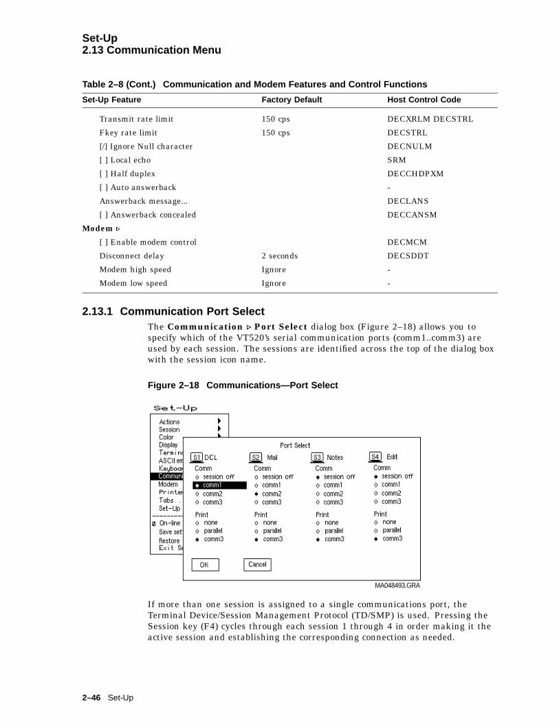
Set-Up2.13 Communication Menu
Table 2–8 (Cont.) Communication and Modem Features and Control Functions
Set-Up Feature Factory Default Host Control Code
Transmit rate limit 150 cps DECXRLM DECSTRL
Fkey rate limit 150 cps DECSTRL
[/] Ignore Null character DECNULM
[ ] Local echo SRM
[ ] Half duplex DECCHDPXM
[ ] Auto answerback -
Answerback message... DECLANS
[ ] Answerback concealed DECCANSM
Modem .
[ ] Enable modem control DECMCM
Disconnect delay 2 seconds DECSDDT
Modem high speed Ignore -
Modem low speed Ignore -
2.13.1 Communication Port SelectThe Communication . Port Select dialog box (Figure 2–18) allows you tospecify which of the VT520’s serial communication ports (comm1..comm3) areused by each session. The sessions are identified across the top of the dialog boxwith the session icon name.
Figure 2–18 Communications—Port Select
MA048493.GRA
If more than one session is assigned to a single communications port, theTerminal Device/Session Management Protocol (TD/SMP) is used. Pressing theSession key (F4) cycles through each session 1 through 4 in order making it theactive session and establishing the corresponding connection as needed.
2–46 Set-Up
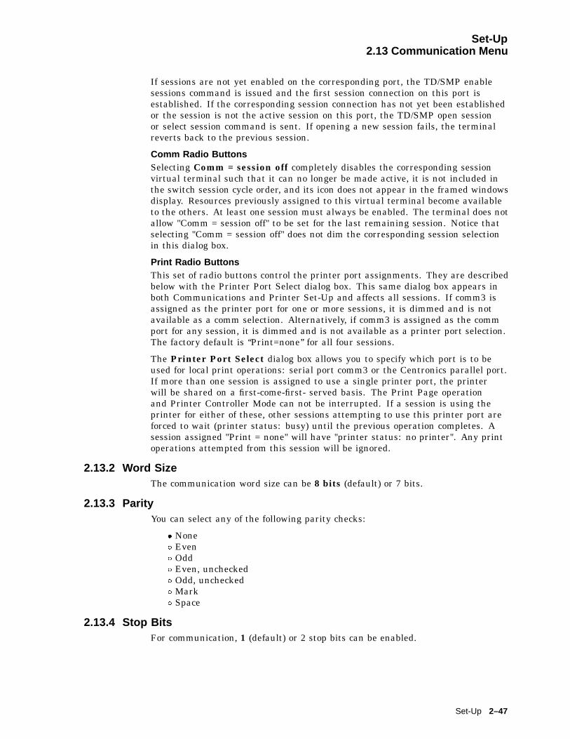
Set-Up2.13 Communication Menu
If sessions are not yet enabled on the corresponding port, the TD/SMP enablesessions command is issued and the first session connection on this port isestablished. If the corresponding session connection has not yet been establishedor the session is not the active session on this port, the TD/SMP open sessionor select session command is sent. If opening a new session fails, the terminalreverts back to the previous session.
Comm Radio ButtonsSelecting Comm = session off completely disables the corresponding sessionvirtual terminal such that it can no longer be made active, it is not included inthe switch session cycle order, and its icon does not appear in the framed windowsdisplay. Resources previously assigned to this virtual terminal become availableto the others. At least one session must always be enabled. The terminal does notallow "Comm = session off" to be set for the last remaining session. Notice thatselecting "Comm = session off" does not dim the corresponding session selectionin this dialog box.
Print Radio ButtonsThis set of radio buttons control the printer port assignments. They are describedbelow with the Printer Port Select dialog box. This same dialog box appears inboth Communications and Printer Set-Up and affects all sessions. If comm3 isassigned as the printer port for one or more sessions, it is dimmed and is notavailable as a comm selection. Alternatively, if comm3 is assigned as the commport for any session, it is dimmed and is not available as a printer port selection.The factory default is ‘‘Print=none’’ for all four sessions.
The Printer Port Select dialog box allows you to specify which port is to beused for local print operations: serial port comm3 or the Centronics parallel port.If more than one session is assigned to use a single printer port, the printerwill be shared on a first-come-first- served basis. The Print Page operationand Printer Controller Mode can not be interrupted. If a session is using theprinter for either of these, other sessions attempting to use this printer port areforced to wait (printer status: busy) until the previous operation completes. Asession assigned "Print = none" will have "printer status: no printer". Any printoperations attempted from this session will be ignored.
2.13.2 Word SizeThe communication word size can be 8 bits (default) or 7 bits.
2.13.3 ParityYou can select any of the following parity checks:
� None� Even� Odd� Even, unchecked� Odd, unchecked� Mark� Space
2.13.4 Stop BitsFor communication, 1 (default) or 2 stop bits can be enabled.
Set-Up 2–47
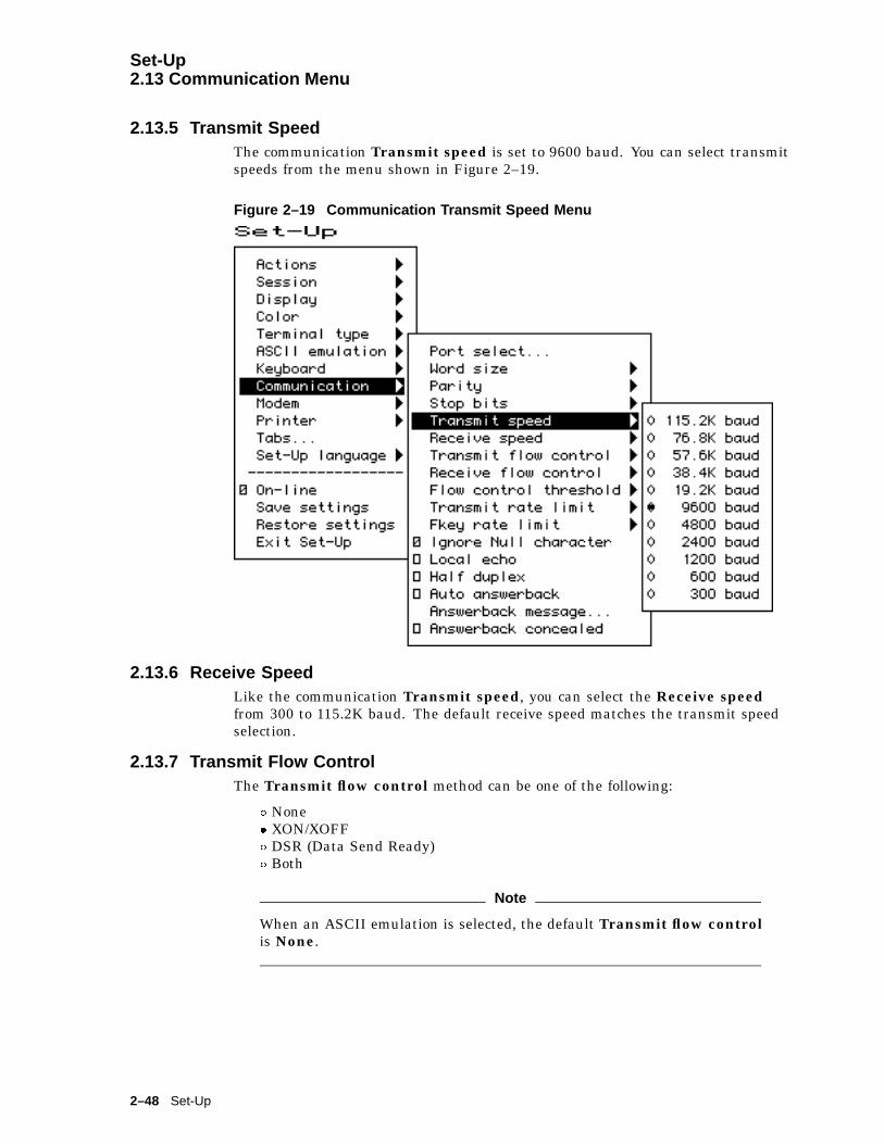
Set-Up2.13 Communication Menu
2.13.5 Transmit SpeedThe communication Transmit speed is set to 9600 baud. You can select transmitspeeds from the menu shown in Figure 2–19.
Figure 2–19 Communication Transmit Speed Menu
2.13.6 Receive SpeedLike the communication Transmit speed, you can select the Receive speedfrom 300 to 115.2K baud. The default receive speed matches the transmit speedselection.
2.13.7 Transmit Flow ControlThe Transmit flow control method can be one of the following:
� None� XON/XOFF� DSR (Data Send Ready)� Both
Note
When an ASCII emulation is selected, the default Transmit flow controlis None.
2–48 Set-Up
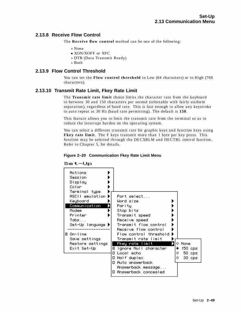
Set-Up2.13 Communication Menu
2.13.8 Receive Flow ControlThe Receive flow control method can be one of the following:
� None� XON/XOFF or XPC� DTR (Data Transmit Ready)� Both
2.13.9 Flow Control ThresholdYou can set the Flow control threshold to Low (64 characters) or to High (768characters).
2.13.10 Transmit Rate Limit, Fkey Rate LimitThe Transmit rate limit choice limits the character rate from the keyboardto between 30 and 150 characters per second (selectable with fairly uniformseparation), regardless of baud rate. This is fast enough to allow any keystroketo auto repeat at 30 Hz (baud rate permitting). The default is 150.
This feature allows you to limit the transmit rate from the terminal so as toreduce the interrupt burden on the operating system.
You can select a different transmit rate for graphic keys and function keys usingFkey rate limit. The F keys transmit more than 1 byte per key press. Thisfunction may be selected through the DECXRLM and DECTRL control function.Refer to Chapter 5, for details.
Figure 2–20 Communication Fkey Rate Limit Menu
Set-Up 2–49
Set-Up2.13 Communication Menu
2.13.11 Ignore Null CharacterThe Ignore Null setting causes the terminal to discard Null charactersimmediately without buffering them. This allows NUL to be used as a timefill character to pace terminal output without overflowing the receive characterbuffer. To pass NUL control codes to a printer, you must deselect the IgnoreNull character check box.
2.13.12 Local EchoWith Local echo enabled, most characters sent from the keyboard to the hostare also displayed on the screen. The answerback message and XON/XOFFs arenot echoed locally. Everything else is.
This feature corresponds to the SRM control function described in Chapter 5.
Note
Local echo is different from the "Local" setting of On-line in the mainmenu of the Set-Up directory. Local echo causes keystrokes to be echoedon the screen, but it does not direct keyboard input to the ANSI parser,which also updates the screen. Local echo is temporarily disabled whenthe terminal is in either Local mode or Local Controller mode, becausethe keyboard input is already being redirected to the screen through theparser or to the printer.
2.13.13 Half DuplexYou can enable or disable Half duplex communication. The default is disabled.Half duplex communication is available only on the Comm1 communications port.If communication is set for the Comm2 port, this feature is disabled (dimmed).
2.13.14 Auto AnswerbackThis item is used to enable or disable Auto answerback on power-up or uponconnection. The factory default is disabled.
2.13.15 Answerback MessageEach session can have an answerback message. The Answerback message . . .menu item invokes a dialog box with a 30-character limit. All characters thatcan be generated by the keyboard are legal in this field (including primary andsecondary keyboard language characters). As such, no errors are reported, exceptwhen trying to enter more than 30 characters. In this case, the bell rings (ifenabled), and no more characters are accepted. The factory default message is nomessage at all (a blank field).
If an Answerback message is currently defined, the message is displayed in thetext entry area. The <x or Delete key can then be used to delete backwards andenter a new Answerback message.
2–50 Set-Up

Set-Up2.13 Communication Menu
Figure 2–21 Communication Answerback Dialog Box
Control characters are displayed using the CRM font. Pressing Return enters areturn character in the Answerback message. Pressing + with the highlightingcursor in the Answerback text field moves to the OK button.
The current Answerback message is displayed in the answerback dialogbox unless Answerback concealed is selected. In this case, the previousAnswerback message is not shown. Choosing the OK button to enter a newAnswerback message clears the Answerback concealed check box.
2.13.16 Answerback ConcealedChanges to this field take effect immediately. The factory default is disabled.
If disabled, the Answerback message is visible in Set-Up. If enabled, the messageis not visible and the text "<concealed>" replaces the message. The only way toreturn this field to disabled (visible) is to enter a new message.
Set-Up 2–51

Set-Up2.14 Modem Menu
2.14 Modem Menu
Figure 2–22 Modem Menu
2.14.1 Enable Modem ControlThe field allows you to select whether the additional hardware control signalsat the interface connector are used for modem control. Modem control disabledis also referred to as "Data leads only." Refer to Chapter 9 for details on modemcontrol signals.
This feature corresponds to DECMCM in Chapter 5.
2.14.2 Disconnect DelayWhen modem control is enabled, the Disconnect delay feature determinesthe time allowed before the terminal disconnects from the communications linewhen the received line signal detect (RLSD) is lost. Disconnect delay is in effectonly when RLSD (CD) is lost. If DSR is lost, the terminal performs a disconnectimmediately. The following selections are available:
� 2 seconds� 60 ms� No disconnect
All countries except the United Kingdom should use a delay of 2 seconds. The 60ms delay is for use in the United Kingdom.
If the VT520 detects a loss of carrier and you selected No disconnect, the VT520ignores RLSD (CD) after the beginning of the connection.
If you try to disconnect and reconnect the line, the VT520 checks to "see" if RLSDis asserted before granting the connection. Once it is connected, the terminalignores the loss of carrier.
You can select disconnect delay through Set-Up or through control functionDECDDT. Refer to Chapter 9 for details on the connect and disconnect process.
2–52 Set-Up
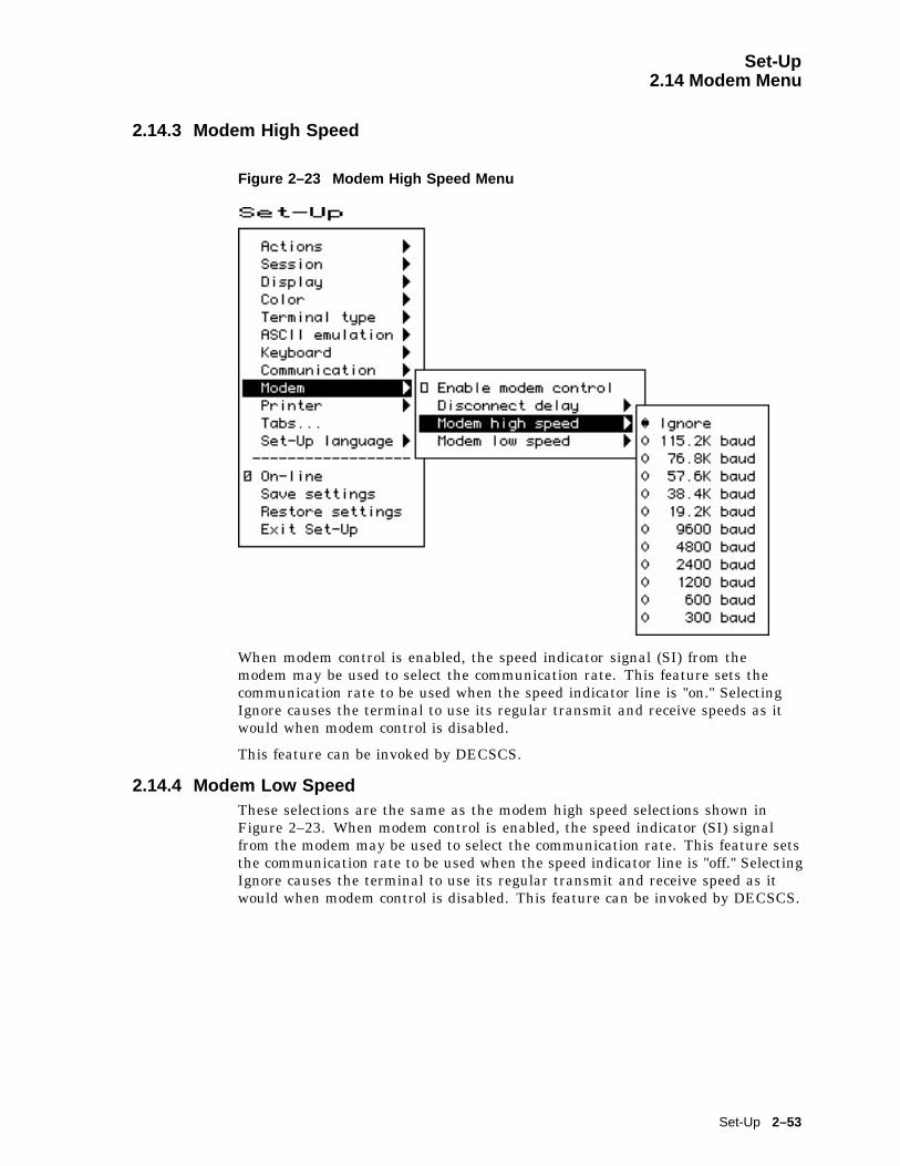
Set-Up2.14 Modem Menu
2.14.3 Modem High Speed
Figure 2–23 Modem High Speed Menu
When modem control is enabled, the speed indicator signal (SI) from themodem may be used to select the communication rate. This feature sets thecommunication rate to be used when the speed indicator line is "on." SelectingIgnore causes the terminal to use its regular transmit and receive speeds as itwould when modem control is disabled.
This feature can be invoked by DECSCS.
2.14.4 Modem Low SpeedThese selections are the same as the modem high speed selections shown inFigure 2–23. When modem control is enabled, the speed indicator (SI) signalfrom the modem may be used to select the communication rate. This feature setsthe communication rate to be used when the speed indicator line is "off." SelectingIgnore causes the terminal to use its regular transmit and receive speed as itwould when modem control is disabled. This feature can be invoked by DECSCS.
Set-Up 2–53

Set-Up2.15 Printer Menu
2.15 Printer Menu
Figure 2–24 Printer Menu
Printer features shown in Figure 2–24 correspond to the control functions listedin Table 2–9. These functions are described in Chapter 5 and Chapter 10.
2.15.1 Port SelectThe Port select menu is the same one that appears in the Communicationmenu (see Figure 2–18). It is displayed in both areas to be easy to find whetheryou are selecting the printer port or the host port. Having a single feature avoidscomplex interactions between printer port and host port selections.
2.15.2 Print ModeThe Print mode menu allows you to select the printer operating mode as follows:
� Normal� Autoprint� Controller
2–54 Set-Up

Set-Up2.15 Printer Menu
Note
We recommend that you do not save the Controller mode selection in NVRbecause this may result in a "hung" terminal if the printer does not haveDTR asserted.
Local echo is temporarily disabled when the terminal is in either Localmode or Local Controller mode, because the keyboard input is alreadybeing redirected to the screen through the parser or to the printer.
Table 2–9 Printer Features and Control Functions
Set-Up Feature Factory Default Host Control Code
Printer .
Port select S1=comm1, S2=comm2,Print=comm3
DECSCP
Print mode Normal MC
Printer type DEC ANSI DECSPRTT DECSDPT
DEC/ISO char sets National only DECSDPT
PC character sets PC International (437) DECSPPCS
Same as receive
Print extent Full page DECPEX
Print terminator None DECPFF
———————————–
Serial print speed 4800 baud DECSCS
[ ] 2-way communication MC
Transmit flow control XON/XOFF DECSFC
Receive flow control XON/XOFF DECSFC
Word size 8 bits DECSPP
Parity None DECSPP
Stop bits 1 bit DECSPP
2.15.3 Printer TypeYou can select the printer type as follows:
� DEC ANSI� IBM ProPrinter� DEC + IBM
2.15.4 Printer Character SetsThe printer character set menus allow you to match the characters printed to thecharacter sets the printer is capable of supporting.
Set-Up 2–55
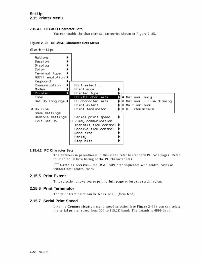
Set-Up2.15 Printer Menu
2.15.4.1 DEC/ISO Character SetsYou can enable the character set categories shown in Figure 2–25.
Figure 2–25 DEC/ISO Character Sets Menu
2.15.4.2 PC Character SetsThe numbers in parentheses in this menu refer to standard PC code pages. Referto Chapter 10 for a listing of the PC character sets.
Same as receive—Use IBM ProPrinter sequences with control codes orwithout host control codes.
2.15.5 Print ExtentThis selection allows you to print a full page or just the scroll region.
2.15.6 Print TerminatorThe print terminator can be None or FF (form feed).
2.15.7 Serial Print SpeedLike the Communication menu speed selection (see Figure 2–19), you can selectthe serial printer speed from 300 to 115.2K baud. The default is 4800 baud.
2–56 Set-Up

Set-Up2.15 Printer Menu
Figure 2–26 PC Character Sets Menu
2.15.8 2-Way CommunicationThis item allows you to enable and disable bidirectional communications on theserial printer port. The default is 2-way communication disabled.
2.15.9 Transmit Flow ControlThe printer transmit flow control method can be one of the following:
� None� XON/XOFF� DSR (Data Send Ready)� Both
2.15.10 Receive Flow ControlThe printer receive flow control method can be one of the following:
� None� XON/XOFF� DTR (Data Terminal Ready)� Both
2.15.11 Word SizeThe printer word size can be 8 bits (default) or 7 bits.
Set-Up 2–57

Set-Up2.15 Printer Menu
2.15.12 ParityYou can select any of the following parity checks to the printer:
� None� Even� Odd� Mark� Space
2.15.13 Stop BitsFor the printer, 1 (default) or 2 stop bits can be enabled.
2.15.14 Same as ReceiveThis item allows you to set the transmit speed to be the same as the receive speedon the printer port.
2.16 Tabs . . .The Tabs . . . menu item is used to invoke the Tab Set-Up dialog box, displayinga 132-column tab ruler. Figure 2–27 shows that tab stops are indicated by theletter T.
The highlighting cursor is initially displayed over the entire tab field. The normalcharacter cursor appears in column 1 of the tab field.
The ( and ) keys move the cursor within the tab field. Pressing Tab
advances the cursor to the next tab stop in the tab field (if any). The charactercursor automatically wraps between the end of the first row and the beginning ofthe second row in the tab field.
2–58 Set-Up

Set-Up2.16 Tabs . . .
Figure 2–27 Tab Set-Up Dialog Box
The labeled buttons allow you to clear all tabs or to set 8-column tabs directly. Toset individual tabs:
1. Position the cursor in the desired column.
2. Press Enter to set or clear a tab in that column.
Tab setting can also be invoked by the HTS and DECCTS control functions.
2.17 SoundThe VT520 is capable of producing a range of sound frequencies. Examples:
To communicate . . . Sound used
Power on 125 ms beep
Attention warning (also ^G) 125 ms beep
Programmable Alarm Four short beeps in rapid succession, pause 0.5seconds repeat. Alarm 1 uses C. Alarm 2 uses Eb.
Sticky keys on Series of three rising notes (short beeps Eb Ab C)
Sticky keys off Series of three falling notes (C Ab Eb)
Hourly chime 125 ms beep
Keyclick 2 ms beep
Margin bell 125 ms beep
Set-Up 2–59
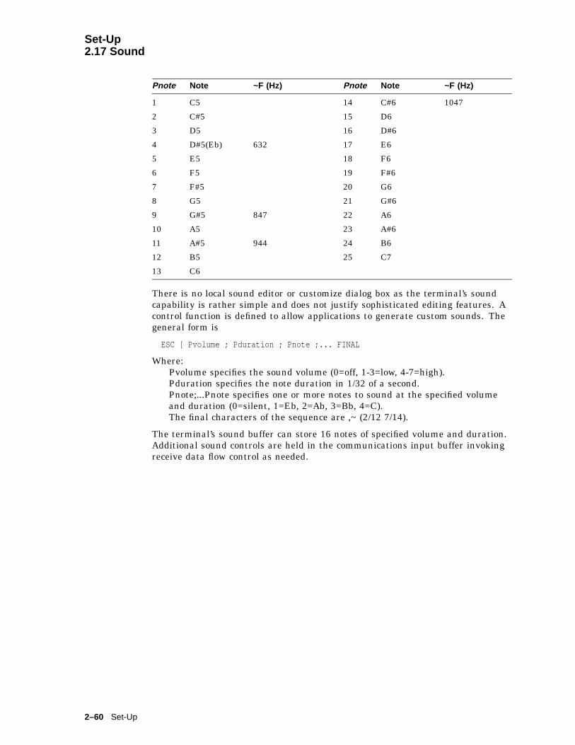
Set-Up2.17 Sound
Pnote Note ~F (Hz) Pnote Note ~F (Hz)
1 C5 14 C#6 1047
2 C#5 15 D6
3 D5 16 D#6
4 D#5(Eb) 632 17 E6
5 E5 18 F6
6 F5 19 F#6
7 F#5 20 G6
8 G5 21 G#6
9 G#5 847 22 A6
10 A5 23 A#6
11 A#5 944 24 B6
12 B5 25 C7
13 C6
There is no local sound editor or customize dialog box as the terminal’s soundcapability is rather simple and does not justify sophisticated editing features. Acontrol function is defined to allow applications to generate custom sounds. Thegeneral form is
ESC [ Pvolume ; Pduration ; Pnote ;... FINAL
Where:Pvolume specifies the sound volume (0=off, 1-3=low, 4-7=high).Pduration specifies the note duration in 1/32 of a second.Pnote;...Pnote specifies one or more notes to sound at the specified volumeand duration (0=silent, 1=Eb, 2=Ab, 3=Bb, 4=C).The final characters of the sequence are ,~ (2/12 7/14).
The terminal’s sound buffer can store 16 notes of specified volume and duration.Additional sound controls are held in the communications input buffer invokingreceive data flow control as needed.
2–60 Set-Up
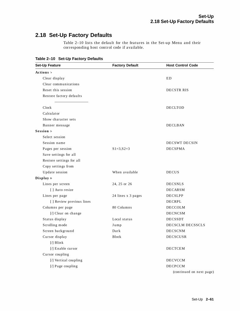
Set-Up2.18 Set-Up Factory Defaults
2.18 Set-Up Factory DefaultsTable 2–10 lists the default for the features in the Set-up Menu and theircorresponding host control code if available.
Table 2–10 Set-Up Factory Defaults
Set-Up Feature Factory Default Host Control Code
Actions .
Clear display ED
Clear communications
Reset this session DECSTR RIS
Restore factory defaults
—————————–
Clock DECLTOD
Calculator
Show character sets
Banner message DECLBAN
Session .
Select session
Session name DECSWT DECSIN
Pages per session S1=3,S2=3 DECSPMA
Save settings for all
Restore settings for all
Copy settings from
Update session When available DECUS
Display .
Lines per screen 24, 25 or 26 DECSNLS
[ ] Auto resize DECARSM
Lines per page 24 lines x 3 pages DECSLPP
[ ] Review previous lines DECRPL
Columns per page 80 Columns DECCOLM
[/] Clear on change DECNCSM
Status display Local status DECSSDT
Scrolling mode Jump DECSCLM DECSSCLS
Screen background Dark DECSCNM
Cursor display Block DECSCUSR
[/] Blink
[/] Enable cursor DECTCEM
Cursor coupling
[/] Vertical coupling DECVCCM
[/] Page coupling DECPCCM
(continued on next page)
Set-Up 2–61

Set-Up2.18 Set-Up Factory Defaults
Table 2–10 (Cont.) Set-Up Factory Defaults
Set-Up Feature Factory Default Host Control Code
Cursor direction Left to right DECRLM
Copy direction Left to right DECRLCM
Zero 0 DECSZS
[ ] Auto wrap DECAWM
[ ] New line mode LNM
[ ] Lock user preferences
[ ] Show control characters CRM
CRT saver 15 minutes DECCRTSM
[/] Host wake-up DECHWUM
Energy saver 15 minutes DECEST
[ ] Overscan DECOSCNM(mono model only)
[ ] Framed windows
Screen alignment... DECALN
Color .
Assign colors DECAC DECCTR
Alternate text colors DECATC
Define colors DECRSTS
Select color map ANSI SGR color DECSTGLT SGR
ASCII color mode Color
Blink and Bold style Foreground DECBBSM
Erase color Text background DECECM
Reverse and Blank attributes
[/] Intensity attributes
Terminal type .
Emulation mode VT520... DECTME
Terminal ID to host VT520 DECTID
VT default char set ISO Latin-1 SCS
PCTerm character set PC International (437) DECPCTERM
[ ] 7-bit NRCS characters DECNRCM
[/] Transmit 7-bit controls S7C1T
ASCII emulation .
Data lines 24 Lines
Pages 1 x Lines
Attribute Char
Write protect attributes
[ ] Blank
[ ] Underline
(continued on next page)
2–62 Set-Up
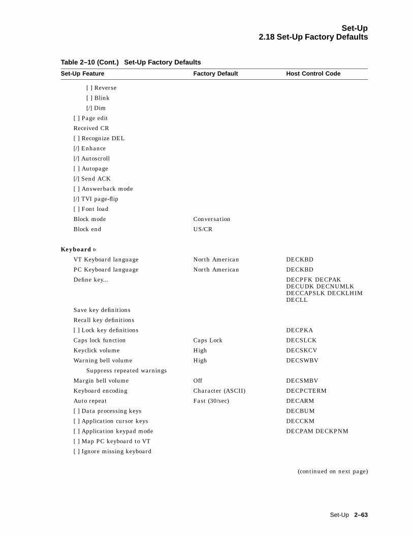
Set-Up2.18 Set-Up Factory Defaults
Table 2–10 (Cont.) Set-Up Factory Defaults
Set-Up Feature Factory Default Host Control Code
[ ] Reverse
[ ] Blink
[/] Dim
[ ] Page edit
Received CR
[ ] Recognize DEL
[/] Enhance
[/] Autoscroll
[ ] Autopage
[/] Send ACK
[ ] Answerback mode
[/] TVI page-flip
[ ] Font load
Block mode Conversation
Block end US/CR
Keyboard .
VT Keyboard language North American DECKBD
PC Keyboard language North American DECKBD
Define key... DECPFK DECPAKDECUDK DECNUMLKDECCAPSLK DECKLHIMDECLL
Save key definitions
Recall key definitions
[ ] Lock key definitions DECPKA
Caps lock function Caps Lock DECSLCK
Keyclick volume High DECSKCV
Warning bell volume High DECSWBV
Suppress repeated warnings
Margin bell volume Off DECSMBV
Keyboard encoding Character (ASCII) DECPCTERM
Auto repeat Fast (30/sec) DECARM
[ ] Data processing keys DECBUM
[ ] Application cursor keys DECCKM
[ ] Application keypad mode DECPAM DECKPNM
[ ] Map PC keyboard to VT
[ ] Ignore missing keyboard
(continued on next page)
Set-Up 2–63

Set-Up2.18 Set-Up Factory Defaults
Table 2–10 (Cont.) Set-Up Factory Defaults
Set-Up Feature Factory Default Host Control Code
Communication .
Port select S1=comm1, S2=comm2,Print=comm3
DECSCP
Word size 8 bits DECSPP
Parity None DECSPP
Stop bits 1 bit DECSPP
Transmit speed 9600 DECSCS
Receive speed Transmit speed DECSCS
Transmit flow control XON/XOFF DECSFC
Receive flow control XON/XOFF or XPC DECSFC
Flow control threshold Low (64)
Transmit rate limit 150 cps DECXRLM DECSTRL
Fkey rate limit 150 cps DECSTRL
[/] Ignore Null character DECNULM
[ ] Local echo SRM
[ ] Half duplex DECCHDPXM
[ ] Auto answerback
Answerback message... DECLANS
[ ] Answerback concealed DECCANSM
Modem .
[ ] Enable modem control DECMCM
Disconnect delay 2 seconds DECSDDT
Modem high speed Ignore
Modem low speed Ignore
Printer .
Port select S1=comm1, S2=comm2,Print=comm3
DECSCP
Print mode Normal MC
Printer type DEC ANSI DECSPRTT DECSDPT
DEC/ISO char sets National only DECSDPT
PC character sets PC International (437) DECSPPCS
Same as receive
Print extent Full page DECPEX
Print terminator None DECPFF
—————————–
Serial print speed 4800 baud DECSCS
(continued on next page)
2–64 Set-Up
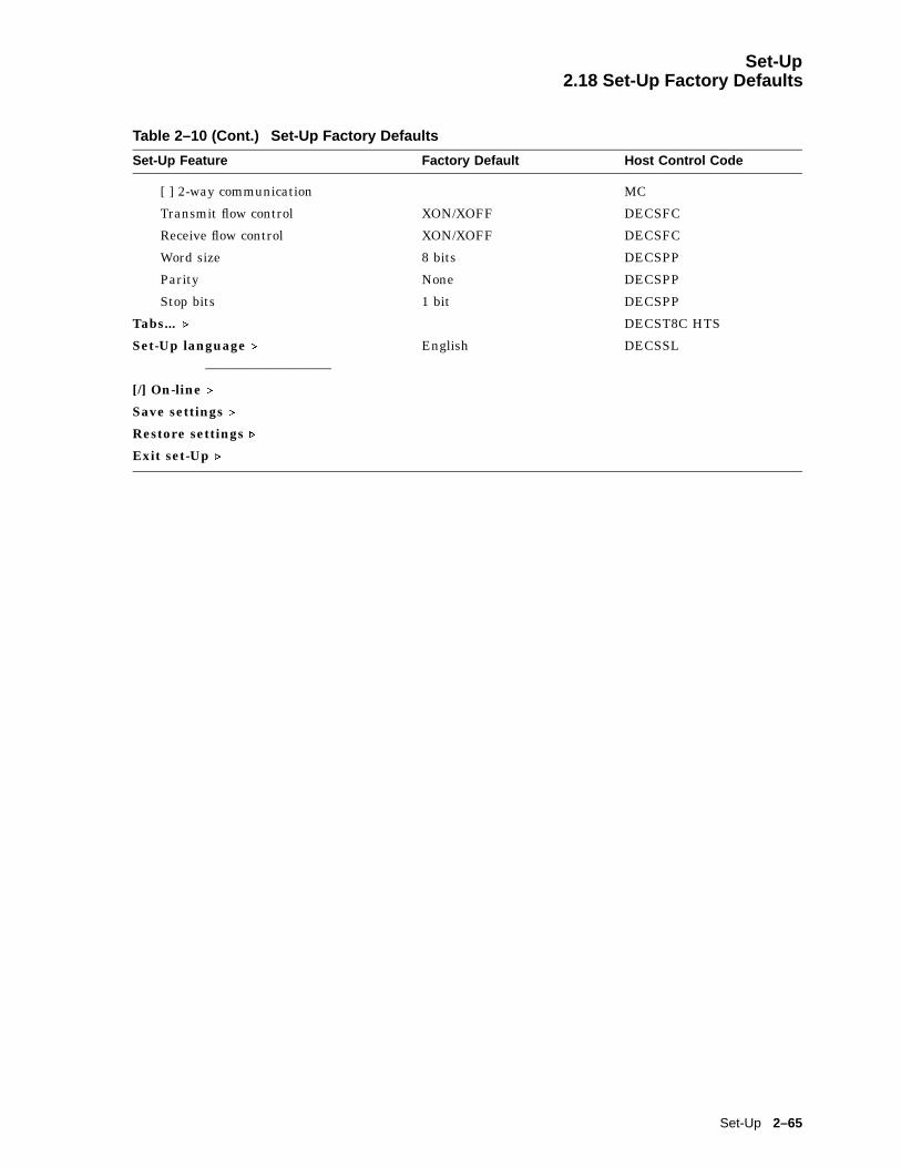
Set-Up2.18 Set-Up Factory Defaults
Table 2–10 (Cont.) Set-Up Factory Defaults
Set-Up Feature Factory Default Host Control Code
[ ] 2-way communication MC
Transmit flow control XON/XOFF DECSFC
Receive flow control XON/XOFF DECSFC
Word size 8 bits DECSPP
Parity None DECSPP
Stop bits 1 bit DECSPP
Tabs... . DECST8C HTS
Set-Up language . English DECSSL
—————————–
[/] On-line .
Save settings .
Restore settings .
Exit set-Up .
Set-Up 2–65


3Desktop Features
3.1 IntroductionTo enhance productivity, the VT520 provides local desktop features that can beused at any time the terminal is powered up, even when the terminal is notconnected to a host. These features are:
• Calculator
• Clock
• Show character sets
• Banner message
• Copy and paste
This chapter describes these desktop features and their interaction with theterminal.
3.2 Invoking Desktop FeaturesOverviewThe local functions can be accessed through Set-Up or through a user-programmable key combination. Chapter 2, Set-Up, describes how to invokethese desktop features and how to assign a key combination to a specific feature.When one is invoked, the screen is partially obscured by that feature. PressingCtrl/Z , F10 ( Exit ), or ESC exits the current desktop feature and reveals the entirescreen contents.
From the Actions menu, you can invoke Clock, Calculator, Show charactersets and the Banner message. When the feature is highlighted (displayed inreverse video), press Enter or Return to enable the feature. A quick start summaryof some keyboard features is provided, as well as how to implement the Copyand Paste function. You can copy and paste within a session and betweensessions.
Desktop Features 3–1

Desktop Features3.2 Invoking Desktop Features
MA049193.GRA
While these desktop features are enabled, other terminal functions are disabled.Press Ctrl Z, F10 , Exit , or Esc to exit the feature.
3.3 CalculatorYou can enable the Calculator function in Set-Up by pressing Caps Lock Alt/F12
if you are not in an ASCII emulation mode.
When you select the Calculator function, the terminal displays a simplecalculator. See the leftmost layout in Figures 3–1 and 3–2. The keypad keys mapdirectly to the calculator keys. The layout depends on whether a VT or EnhancedPC keyboard is attached, and whether a modifier key (Shift or Alt) is currentlyheld down.
When a keypad key is pressed, the corresponding key is highlighted (shownin reverse video) on the screen. If a modifier key is pressed down, the displaychanges to show the new keypad assignment. See the two rightmost layouts inFigures 3–1 and 3–2. All keys not associated with the calculator are ignored.
3–2 Desktop Features

Desktop Features3.3 Calculator
Figure 3–1 Calculator with VT Keyboard Layout
Dec Dec Dec
Normal Shift Down Alt Down
Hex Oct Hex Oct Hex Oct
M 99999999. × 99999999. × M 99999999. ×
÷ × ± RCL 1/X X² B C D
8 9
InsResult
VT keypad
M
7 7
AC/E
0 0 0
8 9 −
PF2 PF3
− 8 9 E
5 6
PF4
STO
4 4
7
0
5 6 + + 5 6 F
2 3
Enter
PF1
1 1
4
2 3=
−
2 3=
8
.
7
1
.
,
.
5
9
4
2
6
1 3
.
In addition to the numbers on the numeric keypad, you can use the followingkeys with the calculator:
Key Function
H , O , or D Select hexadecimal, octal, or decimal modes, respectively.The radix is indicated by a radio button. The first letter ofeach choice is underlined to remind the user of how to selectit.
Arrow keys Move the position of the calculator on the screen.
Shift Changes the keypad display to allow you to select STO , RCL ,1/x , X² , and Insert Result ( Shift/Enter ).
Alt Changes the keypad display to hexadecimal and allows youto select keys A through F on the numeric keypad.
C/E Clears the entry.
STO Stores the number from the display in memory.
RCL Recalls the number from memory and places it in the display.
Shift/Enter(Insert Results)
Inserts the result at the current cursor position after exitingthe calculator feature.
Some keys on the main keypad can also be used for calculator functions:
Desktop Features 3–3
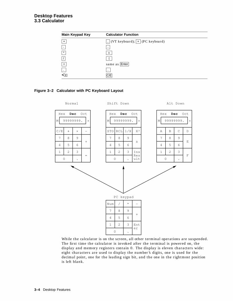
Desktop Features3.3 Calculator
Main Keypad Key Calculator Function
+ , (VT keyboard); + (PC keyboard)
- -
* �
/ �
= same as Enter
. .
<x C/E
Figure 3–2 Calculator with PC Keyboard Layout
Dec Dec Dec
Normal Shift Down Alt Down
Hex Oct Hex Oct Hex Oct
M 99999999. × 99999999. × M 99999999. ×
÷ × − RCL 1/X X² B C D
8 9
InsResult
M
7 7
AC/E
0 0 0
8 9+ ±
8 9E
5 6
Enter
STO
4 4
7
PC keypad
5 6
=
−
5 6
F2 3
Num
1 1
4
0
2 3
+
2 3
/
.
7
1
. .
8
*
4 5
9
1 2
6
3
.
While the calculator is on the screen, all other terminal operations are suspended.The first time the calculator is invoked after the terminal is powered on, thedisplay and memory registers contain 0. The display is eleven characters wide:eight characters are used to display the number’s digits, one is used for thedecimal point, one for the leading sign bit, and the one in the rightmost positionis left blank.
3–4 Desktop Features

Desktop Features3.3 Calculator
The calculator allows the user to add, subtract, multiply, and divide real numbersin the range [-99,999,999. through +99,999,999.]. While one of these operationsis in progress, the calculator displays the corresponding symbol [+ - � �] tothe right of the display. (See the � in the figures.) You can also computethe reciprocal or the square of a number by pressing the 1/X or X² keys,respectively.
All calculator math operations have equal priority except 1/X and X². If a result iswider than the display, then a rounded number will be displayed. The unroundedresult will continue to be used in subsequent calculations.
The calculator has a memory register in which an intermediate result can bestored. When you press STO , you replace the content of this register with thenumber in the display. When you press RCL , you place the number from memoryin the display. If any value is stored in memory, the calculator displays the letterM to the left of the display.
The number in the display (usually the last result) can be inserted at the currentcursor position by pressing Shift/Enter (Insert Result), which exits the calculatorand transmits the data to the host.
The calculator can also be used with hexadecimal and octal numbers in additionto the default (decimal). The H , O , or D keys put the calculator inhexadecimal, octal, or decimal modes, respectively. The current mode is inplain text and the other two modes are displayed with the dim attribute. Inhexadecimal mode, the numbers A through F are entered by holding down Alt
and typing the corresponding keypad key. See Figures 3–1 and 3–2. The decimalpoint cannot be used in the hexadecimal or octal modes, and any fractional partis truncated in these two modes.
3.4 ClockYou can enable the Clock feature without entering Set-Up by pressingCaps Lock Alt F11 if you are either in a VT or an SCO console emulation mode.
The current time is displayed in the status line, if this feature is enabled. If the12-hour format is selected, an A or P is displayed after the minutes.
The Clock function allows the current time to be set, the hourly chime to beenabled or disabled, and the alarms to be set and armed or disarmed. Thecurrent time can also be set from the host through an escape sequence. When theclock function is selected, the window shown in Figure 3–3 is displayed on thescreen.
Desktop Features 3–5
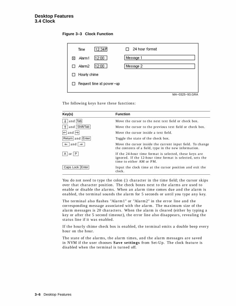
Desktop Features3.4 Clock
Figure 3–3 Clock Function
MA−0325−93.GRA
The following keys have these functions:
Key(s) Function
+ and Tab Move the cursor to the next text field or check box.
* and Shift/Tab Move the cursor to the previous text field or check box.
( and ) Move the cursor inside a text field.
Return and Enter Toggle the state of the check box.
( and ) Move the cursor inside the current input field. To changethe contents of a field, type in the new information.
A or P If the 24-hour time format is selected, these keys areignored. If the 12-hour time format is selected, sets thetime to either AM or PM.
Caps Lock Enter Input the clock time at the cursor position and exit theclock.
You do not need to type the colon (:) character in the time field; the cursor skipsover that character position. The check boxes next to the alarms are used toenable or disable the alarms. When an alarm time comes due and the alarm isenabled, the terminal sounds the alarm for 5 seconds or until you type any key.
The terminal also flashes "Alarm1" or "Alarm2" in the error line and thecorresponding message associated with the alarm. The maximum size of thealarm messages is 20 characters. When the alarm is cleared (either by typing akey or after the 5 second timeout), the error line also disappears, revealing thestatus line if it was enabled.
If the hourly chime check box is enabled, the terminal emits a double beep everyhour on the hour.
The state of the alarms, the alarm times, and the alarm messages are savedin NVM if the user chooses Save settings from Set-Up. The clock feature isdisabled when the terminal is turned off.
3–6 Desktop Features

Desktop Features3.5 Review Previous Lines
3.5 Review Previous LinesIn Set-Up or through software, you can allocate the pages that are assigned toeach session, up to a total of eight pages or nine pages on the color model. WhenReview previous lines is selected, the page memory allocation for a sessionbecomes a single page and a scroll back buffer. You can then use Ctrl* and Ctrl+
keys to scroll up or down to review lines previously scrolled off the screen. (Note:When this feature is enabled, the host cannot write to specific pages, and controlcodes from the host are ignored.)
3.6 Character Set Tables3.6.1 Show Character Sets feature
When you select Show character sets, the current character set is shown onthe screen. Nonprinting characters are shown in control representation modewherever possible.
If you are in either a VT or an SCO console emulation mode, you can enablethe Show character sets desktop feature without entering Set-Up by usingCaps Lock Alt F10 . When the character set is displayed, you can use the following
keys with this feature:
Key Function
Next or Prev
Page Up or Page DownLooks through the available character sets.
Shift A Restores the ASCII character set (when the Line Drawing setis displayed.)
Shift L Displays the line drawing character set, if you are using a VTcharacter set.
Shift T Displays the technical character set.
Shift Enter For the current character set, inserts the highlightedcharacter into text at the current cursor position, if youare using a VT character set.
ASCII terminal emulations support the character sets listed in Table 3–1. Theydo not support any 8-bit or ISO standard character sets.
Table 3–1 ASCII Emulation Character Sets
Emulation Mode Character Set
WYSE 325 Native/WY-50+
WYSE 160/60 Native Native/WY-50+
WYSE PCTerm PC Multilingual (Code Page 850)
WYSE 50+, 150/120 Native/WY-50+
TVI 950, 925, 910+ Native/WY-50+
ADDS A2 Native/WY-50+
Desktop Features 3–7
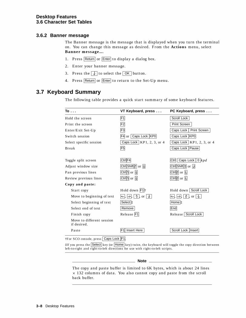
Desktop Features3.6 Character Set Tables
3.6.2 Banner messageThe Banner message is the message that is displayed when you turn the terminalon. You can change this message as desired. From the Actions menu, selectBanner message....
1. Press Return or Enter to display a dialog box.
2. Enter your banner message.
3. Press the + to select the OK button.
4. Press Return or Enter to return to the Set-Up menu.
3.7 Keyboard SummaryThe following table provides a quick start summary of some keyboard features.
To . . . VT Keyboard, press . . . PC Keyboard, press . . .
Hold the screen F1 Scroll Lock
Print the screen F2 Print Screen
Enter/Exit Set-Up F3 Caps Lock Print Screen
Switch session F4 or Caps Lock KP0 Caps Lock KP0
Select specific session Caps Lock KP1, 2, 3, or 4 Caps Lock KP1, 2, 3, or 4
Break F5 Caps Lock Pause
Toggle split screen Ctrl F4 Ctrl Caps Lock 0 kpd
Adjust window size Ctrl Shift * or + Ctrl Shift * or +
Pan previous lines Ctrl * or + Ctrl * or +
Review previous lines Ctrl * or + Ctrl * or +
Copy and paste:
Start copy Hold down F1† Hold down Scroll Lock
Move to beginning of text ( , ) , * , or + ( , ) , * , or +
Select beginning of text Select ‡ Home ‡
Select end of text Remove End
Finish copy Release F1 Release Scroll Lock
Move to different sessionif desired.
Paste F1 Insert Here Scroll Lock Insert
†For SCO console, press Caps Lock F1 .
‡If you press the Select key (or Home key) twice, the keyboard will toggle the copy direction betweenleft-to-right and right-to-left directions for use with right-to-left scripts.
Note
The copy and paste buffer is limited to 6K bytes, which is about 24 lines� 132 columns of data. You also cannot copy and paste from the scrollback buffer.
3–8 Desktop Features

Part IIVT520 ANSI Mode
This part includes the following chapters:
• Chapter 4, ANSI Control Functions Summary
• Chapter 5, ANSI Control Functions
• Chapter 6, SCO Console Emulation
• Chapter 7, Character Sets
• Chapter 8, Keyboard Processing
• Chapter 9, Communications
• Chapter 10, Printer Port

4ANSI Control Functions Summary
4.1 IntroductionThis chapter provides a general description of ANSI control functions. Thischapter provides information on working with 7- and 8-bit environments and theconventions used in each, and it describes the Show control characters Set-Upfeature. In addition, this chapter provides summary tables of the ANSI controlfunctions.
For . . . See page . . .
Control characters 4-1
Control functions 4-5
Working with 7-Bit and 8-Bit environments 4-10
Showing control characters 4-11
ASCII code tables 4-14,15
ANSI control function tables 4-16
VT52 mode escape sequences 4-45
4.2 Control CharactersThe purpose of a control character is to control an action such as line spacing,paging, or data flow. The terminal does not display control characters unless youselect Show control characters from the Display Set-Up menu. There are twogroups of control characters.
C0
C1
7-bit control characters, in columns 0 and 1of the 8-bit code table
8-bit control characters, in columns 8 and 9of the 8-bit code table
Table 4–1 lists the C0 control characters the VT520 recognizes. Table 4–2lists the C1 control characters the VT520 recognizes. You can also code C1control characters as 7-bit escape sequences. Table 4–3 lists the equivalent 7-bitsequences for 8-bit control characters. All three tables give column/row locationsas an unambiguous character representation.
ANSI Control Functions Summary 4–1
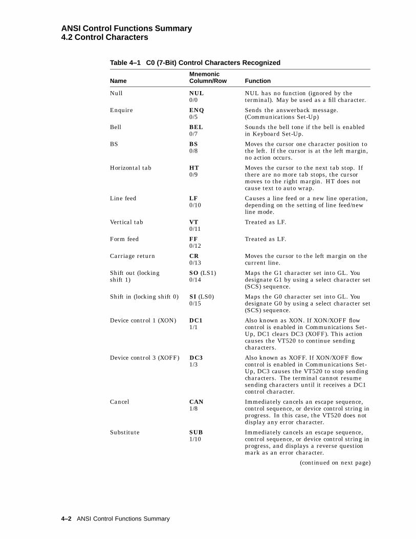
ANSI Control Functions Summary4.2 Control Characters
Table 4–1 C0 (7-Bit) Control Characters Recognized
NameMnemonicColumn/Row Function
Null NUL0/0
NUL has no function (ignored by theterminal). May be used as a fill character.
Enquire ENQ0/5
Sends the answerback message.(Communications Set-Up)
Bell BEL0/7
Sounds the bell tone if the bell is enabledin Keyboard Set-Up.
BS BS0/8
Moves the cursor one character position tothe left. If the cursor is at the left margin,no action occurs.
Horizontal tab HT0/9
Moves the cursor to the next tab stop. Ifthere are no more tab stops, the cursormoves to the right margin. HT does notcause text to auto wrap.
Line feed LF0/10
Causes a line feed or a new line operation,depending on the setting of line feed/newline mode.
Vertical tab VT0/11
Treated as LF.
Form feed FF0/12
Treated as LF.
Carriage return CR0/13
Moves the cursor to the left margin on thecurrent line.
Shift out (lockingshift 1)
SO (LS1)0/14
Maps the G1 character set into GL. Youdesignate G1 by using a select character set(SCS) sequence.
Shift in (locking shift 0) SI (LS0)0/15
Maps the G0 character set into GL. Youdesignate G0 by using a select character set(SCS) sequence.
Device control 1 (XON) DC11/1
Also known as XON. If XON/XOFF flowcontrol is enabled in Communications Set-Up, DC1 clears DC3 (XOFF). This actioncauses the VT520 to continue sendingcharacters.
Device control 3 (XOFF) DC31/3
Also known as XOFF. If XON/XOFF flowcontrol is enabled in Communications Set-Up, DC3 causes the VT520 to stop sendingcharacters. The terminal cannot resumesending characters until it receives a DC1control character.
Cancel CAN1/8
Immediately cancels an escape sequence,control sequence, or device control string inprogress. In this case, the VT520 does notdisplay any error character.
Substitute SUB1/10
Immediately cancels an escape sequence,control sequence, or device control string inprogress, and displays a reverse questionmark as an error character.
(continued on next page)
4–2 ANSI Control Functions Summary

ANSI Control Functions Summary4.2 Control Characters
Table 4–1 (Cont.) C0 (7-Bit) Control Characters Recognized
NameMnemonicColumn/Row Function
Escape ESC1/11
Introduces an escape sequence. ESC alsocancels any escape sequence, controlsequence, or device control string inprogress.
Delete DEL7/15
Ignored when received, unless a 96-character set is mapped into GL. DELis not used as a fill character. Digitaldoes not recommend using DEL as a fillcharacter. Use NUL instead.
Table 4–2 C1 (8-Bit) Control Characters Recognized
NameMnemonicColumn/Row Function
Index IND8/4
Moves the cursor down one line in the samecolumn. If the cursor is at the bottom margin,the page scrolls up.
Next line NEL8/5
Moves the cursor to the first position on the nextline. If the cursor is at the bottom margin, thepage scrolls up.
Horizontal tabset
HTS8/8
Sets a horizontal tab stop at the column wherethe cursor is.
Reverse index RI8/13
Moves the cursor up one line in the samecolumn. If the cursor is at the top margin,the page scrolls down.
Single shift 2 SS28/14
Temporarily maps the G2 character set into GL,for the next graphic character. You designatethe G2 set by using a select character set (SCS)sequence.
Single shift 3 SS38/15
Temporarily maps the G3 character set into GL,for the next graphic character. You designatethe G3 set by using a select character set (SCS)sequence.
Device controlstring
DCS9/0
Introduces a DCS control string. DCS controlstrings are used for loading function keys or asoft character set.
Start of string SOS9/8
Ignored.
DECprivateidentification
DECID9/10
Makes the terminal send its device attributesresponse to the host (same as an ANSI deviceattributes (DA) sequence). Programs should usethe ANSI DA sequence instead. If the printeris in controller mode, the terminal sends thesequence to the printer.
Controlsequenceintroducer
CSI9/11
CSI introduces a control sequence.
(continued on next page)
ANSI Control Functions Summary 4–3

ANSI Control Functions Summary4.2 Control Characters
Table 4–2 (Cont.) C1 (8-Bit) Control Characters Recognized
NameMnemonicColumn/Row Function
Stringterminator
ST9/12
Ends a control string. ST is normally used incombination with DCS, OSC, PM, or APC.
Operatingsystemcommand
OSC9/13
OSC introduces an OSC control string.
Privacy message PM9/14
PM introduces a PM control string. The VT520ignores all PM control strings.
Applicationprogramcommand
APC9/15
APC introduces an application programcommand. The VT520 ignores all APC controlstrings.
Table 4–3 8-Bit Control Characters and Their 7-Bit Equivalents
Name8-BitCharacter
7-BitSequence
Index IND8/4
ESC1/11
D4/4
Next line NEL8/5
ESC1/11
E4/5
Horizontal tab set HTS8/8
ESC1/11
H4/8
Reverse index RI8/13
ESC1/11
M4/13
Single shift 2 SS28/14
ESC1/11
N4/14
Single shift 3 SS38/15
ESC1/11
O4/15
Device control string DCS9/0
ESC1/11
P5/0
Start of string SOS9/8
ESC1/11
X5/8
DEC private identification DECID9/10
ESC1/11
Z5/10
Control sequence introducer CSI9/11
ESC1/11
[5/11
String terminator ST9/12
ESC1/11
\5/12
Operating system command OSC9/13
ESC1/11
]5/13
Privacy message PM9/14
ESC1/11
^5/14
Application program APC9/15
ESC1/11
_5/15
4–4 ANSI Control Functions Summary

ANSI Control Functions Summary4.3 Control Functions
4.3 Control FunctionsYou use control functions to make the terminal perform special actions in yourapplications. Examples:
Move the cursor.Delete a line of text.Select bold or underlined text.Change character sets.Make the terminal emulate a VT52 or VT100 terminal.
There are single-character and multiple-character control functions.
The single-character functions are the C0 and C1 control characters. You can useC0 characters in a 7-bit or 8-bit environment. C1 characters provide a few morefunctions than C0 characters, but you can only use C1 characters directly in an8-bit environment.
Multiple-character control functions provide many more functions than the C0and C1 characters. Multiple-character functions can use control characters andgraphic characters. There are three basic types of multiple-character controlfunctions.
Escape sequencesControl sequencesControl strings
The structure of control functions are defined by ANSI and ISO standards.Many individual sequences are defined by these same standards and are usedthroughout the industry. Others are private sequences, created by manufacturersin accordance with ANSI and ISO standards for use in their own products.
In this manual, control functions created by Digital have the prefix DEC in theirmnemonic name. For example, column mode has the mnemonic DECCOLM. Allother control functions used in the ANSI VT emulations are standardized by ISO.
The following sections describe the format for escape sequences, controlsequences, and device control strings.
Programming TipWhen you use control functions, remember that the binary codes define afunction—not the graphic characters. This manual uses graphic charactersfrom the DEC Multinational character set to show control functions. If you useanother character set, the graphic characters for control functions may change,but the code is always the same.
4.3.1 Sequence FormatThis manual shows escape and control sequences in their 8-bit format. You canalso use equivalent 7-bit sequences (Table 4–3).
The 8-bit format uses the C0 and C1 control characters and ASCII charactersfrom the DEC Multinational character set. The sequences also show eachcharacter’s column/row position in the character set table, below the character.The column/row code eliminates confusion over similar-looking characters such as0 (3/0) and O (4/15).
ANSI Control Functions Summary 4–5

ANSI Control Functions Summary4.3 Control Functions
Note
Spaces appear between characters in a sequence for clarity. These spacesare not part of the sequence. If a space is part of the sequence, the SP(2/0) character appears.
4.3.2 Escape SequencesAn escape sequence uses two or more bytes to define a specific control function.Escape sequences do not include variable parameters, but may includeintermediate characters. Here is the format for an escape sequence.
ESC1/11
I2/0 to 2/15
F3/0 to 7/14
Escapecharacter
Intermediatecharacters(zero or morecharacters)
Finalcharacter(one character)
ESC introduces escape sequences. After receiving the ESC control character, theterminal interprets the next received characters as part of the sequence.
I represents zero or more intermediate characters that can follow the ESCcharacter. Intermediate characters come from the 2/0 through 2/15 range of thecode table.
F is the final character. This character indicates the end of the sequence. Thefinal character comes from the 3/0 through 7/14 range of the code table. Theintermediate and final characters together define a single control function.
For example, the following escape sequence changes the current line of text todouble-width, single-height characters:
ESC1/11
#2/3
63/6
4.3.3 Control SequencesA control sequence uses two or more bytes to define a specific control function.Control sequences usually include variable parameters. Here is the format for acontrol sequence.
CSI9/11
P...P3/0 to 3/15
I...I2/0 to 2/15
F4/0 to 7/14
Controlsequenceintroducer
Parameter(zero or morecharacters)
Intermediate(zero or morecharacters)
Final(one character)
4.3.3.1 Control Sequence IntroducerCSI is the control sequence introducer. You can also use the equivalent 7-bitsequence, ESC (1/11) [ (5/11), as a substitute for CSI. After receiving CSI, theterminal interprets the next received characters as part of the sequence.
4–6 ANSI Control Functions Summary
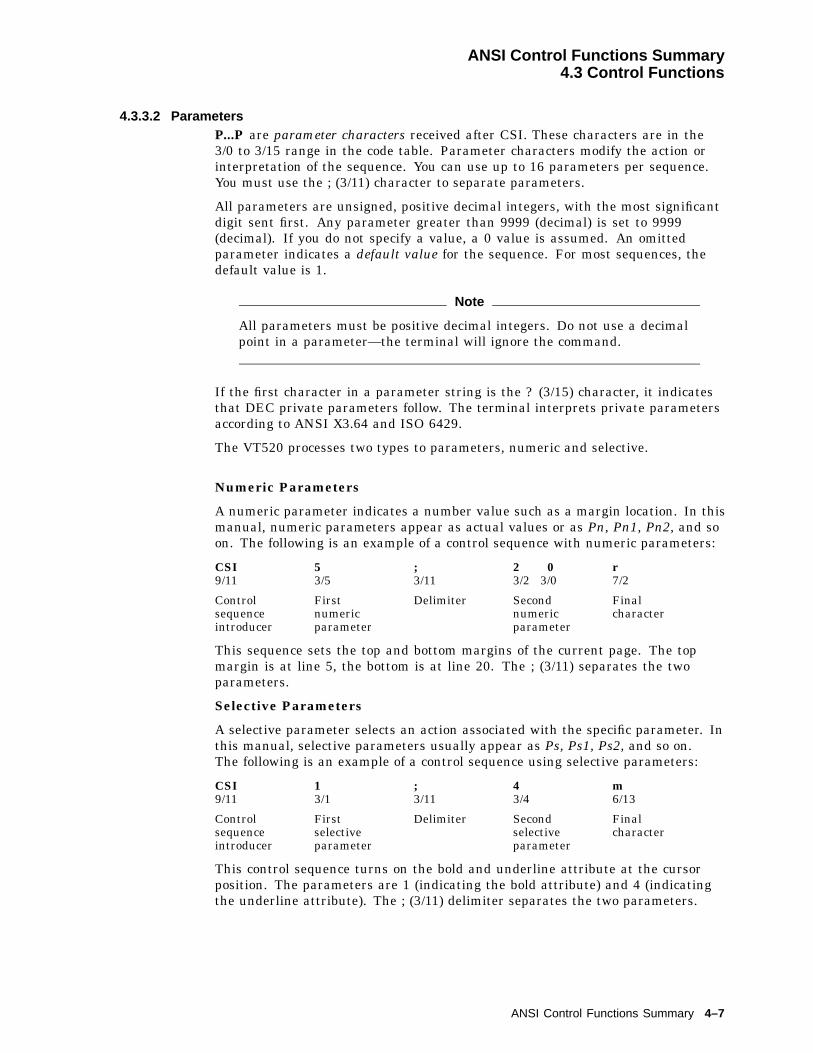
ANSI Control Functions Summary4.3 Control Functions
4.3.3.2 ParametersP...P are parameter characters received after CSI. These characters are in the3/0 to 3/15 range in the code table. Parameter characters modify the action orinterpretation of the sequence. You can use up to 16 parameters per sequence.You must use the ; (3/11) character to separate parameters.
All parameters are unsigned, positive decimal integers, with the most significantdigit sent first. Any parameter greater than 9999 (decimal) is set to 9999(decimal). If you do not specify a value, a 0 value is assumed. An omittedparameter indicates a default value for the sequence. For most sequences, thedefault value is 1.
Note
All parameters must be positive decimal integers. Do not use a decimalpoint in a parameter—the terminal will ignore the command.
If the first character in a parameter string is the ? (3/15) character, it indicatesthat DEC private parameters follow. The terminal interprets private parametersaccording to ANSI X3.64 and ISO 6429.
The VT520 processes two types to parameters, numeric and selective.
Numeric Parameters
A numeric parameter indicates a number value such as a margin location. In thismanual, numeric parameters appear as actual values or as Pn, Pn1, Pn2, and soon. The following is an example of a control sequence with numeric parameters:
CSI9/11
53/5
;3/11
2 03/2 3/0
r7/2
Controlsequenceintroducer
Firstnumericparameter
Delimiter Secondnumericparameter
Finalcharacter
This sequence sets the top and bottom margins of the current page. The topmargin is at line 5, the bottom is at line 20. The ; (3/11) separates the twoparameters.
Selective Parameters
A selective parameter selects an action associated with the specific parameter. Inthis manual, selective parameters usually appear as Ps, Ps1, Ps2, and so on.The following is an example of a control sequence using selective parameters:
CSI9/11
13/1
;3/11
43/4
m6/13
Controlsequenceintroducer
Firstselectiveparameter
Delimiter Secondselectiveparameter
Finalcharacter
This control sequence turns on the bold and underline attribute at the cursorposition. The parameters are 1 (indicating the bold attribute) and 4 (indicatingthe underline attribute). The ; (3/11) delimiter separates the two parameters.
ANSI Control Functions Summary 4–7

ANSI Control Functions Summary4.3 Control Functions
4.3.3.3 Intermediate CharactersI...I are zero or more intermediate characters received after CSI. These charactersare in the 2/0 to 2/15 range.
4.3.3.4 Final CharacterF is the final character from the 4/0 to 7/14 range. The final character indicatesthe end of the sequence. The intermediate and final characters together definea control function. If there are no intermediate characters, the final characterdefines the function.
4.3.4 Device Control StringsDevice control strings (DCS), like control sequences, use two or more bytes todefine specific control functions. However, a DCS also includes a data string.Here is the format for a device control string.
DCS9/0
P...P3/0to3/15
I...I2/0to2/15
F4/0to3/15
Data string************
ST9/12
Devicecontrolstringintroducer
Zero ormorepara-meters
Zero ormoreinter-mediates
Final String Stringterminator
DCS is the device control string introducer. DCS is the C1 control character atposition 9/0. You can also use the equivalent 7-bit sequence, ESC (1/11) P (5/0).After receiving DCS, the terminal processes the next received characters as partof the string function.
P...P are parameter characters received after DCS. The use of parametercharacters in a device control string is a Digital extension to the ANSI syntax.According to ANSI standards, any elements included after DCS are part of thedata string.
Parameter characters are in the 3/0 to 3/15 range. They modify the action orinterpretation of the device control string. You can use up to 16 parameters perstring. Each parameter is separated with a ; (3/11) character. These charactersfollow the same rules as in a control sequence. See the ‘‘Section 4.3.3’’ section inthis chapter.
I...I are zero or more intermediate characters received after CSI. These charactersare in the 2/0 to 2/15 range.
F is the final character in the 4/0 to 7/14 range. The final character indicatesthe end of the string. The intermediate and final characters define the string. Ifthere are no intermediates, the final character defines the string.
Data string follows the final character and usually includes several definitionstrings. Each definition string can be several characters in length. Individualstrings are separated by the ; (3/11) delimiter.
ST is the string terminator. ST (9/12) indicates the end of a string. You can alsouse the equivalent 7-bit sequence, ESC (1/11) \ (5/12).
4–8 ANSI Control Functions Summary
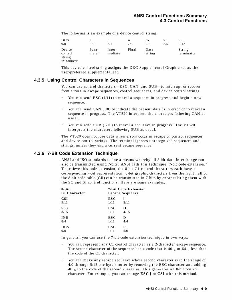
ANSI Control Functions Summary4.3 Control Functions
The following is an example of a device control string:
DCS9/0
03/0
!2/1
u7/5
%2/5
53/5
ST9/12
Devicecontrolstringintroducer
Para-meter
Inter-mediate
Final Datastring
Stringterminator
This device control string assigns the DEC Supplemental Graphic set as theuser-preferred supplemental set.
4.3.5 Using Control Characters in SequencesYou can use control characters—ESC, CAN, and SUB—to interrupt or recoverfrom errors in escape sequences, control sequences, and device control strings.
• You can send ESC (1/11) to cancel a sequence in progress and begin a newsequence.
• You can send CAN (1/8) to indicate the present data is in error or to cancel asequence in progress. The VT520 interprets the characters following CAN asusual.
• You can send SUB (1/10) to cancel a sequence in progress. The VT520interprets the characters following SUB as usual.
The VT520 does not lose data when errors occur in escape or control sequencesand device control strings. The terminal ignores unrecognized sequences andstrings, unless they end a current escape sequence.
4.3.6 7-Bit Code Extension TechniqueANSI and ISO standards define a means whereby all 8-bit data interchange canalso be transmitted using 7-bits. ANSI calls this technique ‘‘7-bit code extension.’’To achieve this code extension, the 8-bit C1 control characters each have acorresponding 7-bit representation. 8-bit graphic characters from the right half ofthe 8-bit code table (GR) can be transmitted in 7-bits by encapsulating them withthe SO and SI control functions. Here are some examples.
8-BitC1 Character
7-Bit Code ExtensionEscape Sequence
CSI9/11
ESC1/11
[5/11
SS38/15
ESC1/11
O4/15
IND8/4
ESC1/11
D4/4
DCS9/0
ESC1/11
P5/0
In general, you can use the 7-bit code extension technique in two ways.
• You can represent any C1 control character as a 2-character escape sequence.The second character of the sequence has a code that is 4016 or 6410 less thanthe code of the C1 character.
• You can make any escape sequence whose second character is in the range of4/0 through 5/15 one byte shorter by removing the ESC character and adding4016 to the code of the second character. This generates an 8-bit controlcharacter. For example, you can change ESC [ to CSI with this method.
ANSI Control Functions Summary 4–9
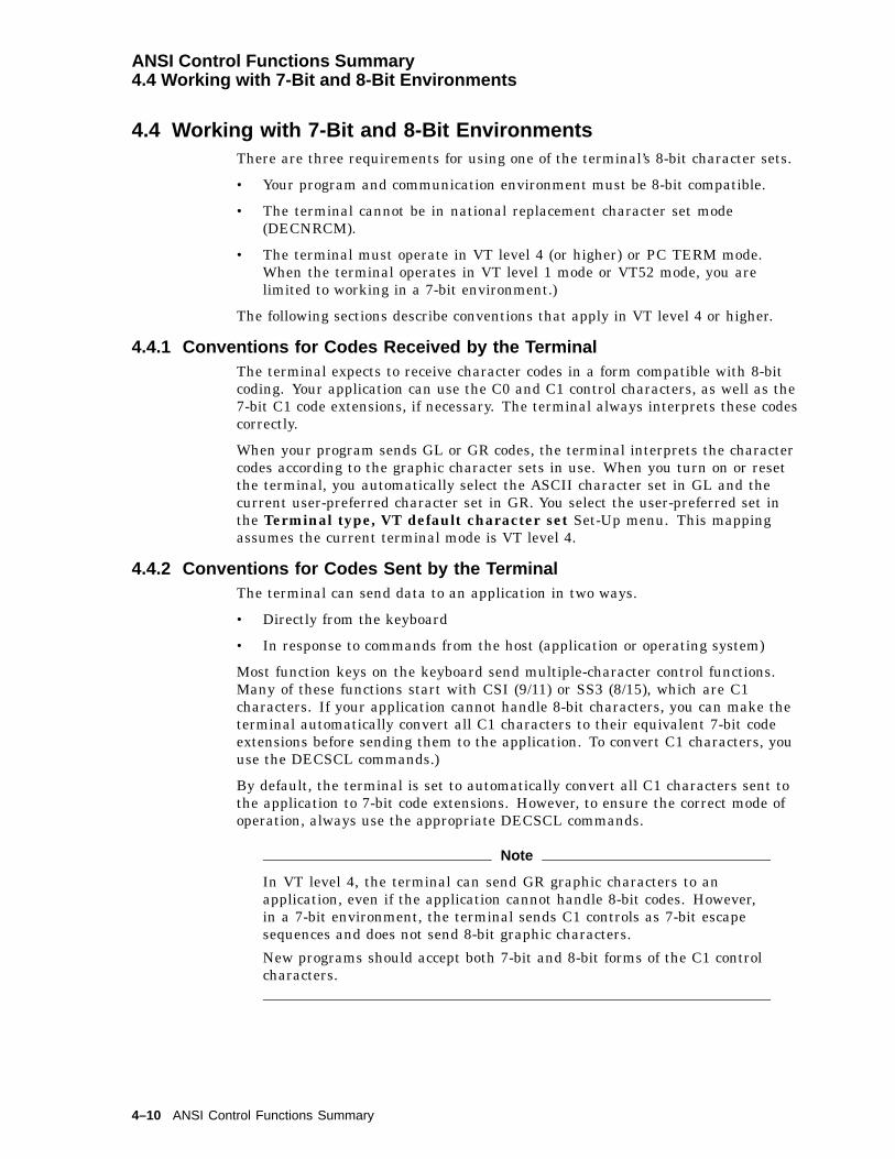
ANSI Control Functions Summary4.4 Working with 7-Bit and 8-Bit Environments
4.4 Working with 7-Bit and 8-Bit EnvironmentsThere are three requirements for using one of the terminal’s 8-bit character sets.
• Your program and communication environment must be 8-bit compatible.
• The terminal cannot be in national replacement character set mode(DECNRCM).
• The terminal must operate in VT level 4 (or higher) or PC TERM mode.When the terminal operates in VT level 1 mode or VT52 mode, you arelimited to working in a 7-bit environment.)
The following sections describe conventions that apply in VT level 4 or higher.
4.4.1 Conventions for Codes Received by the TerminalThe terminal expects to receive character codes in a form compatible with 8-bitcoding. Your application can use the C0 and C1 control characters, as well as the7-bit C1 code extensions, if necessary. The terminal always interprets these codescorrectly.
When your program sends GL or GR codes, the terminal interprets the charactercodes according to the graphic character sets in use. When you turn on or resetthe terminal, you automatically select the ASCII character set in GL and thecurrent user-preferred character set in GR. You select the user-preferred set inthe Terminal type, VT default character set Set-Up menu. This mappingassumes the current terminal mode is VT level 4.
4.4.2 Conventions for Codes Sent by the TerminalThe terminal can send data to an application in two ways.
• Directly from the keyboard
• In response to commands from the host (application or operating system)
Most function keys on the keyboard send multiple-character control functions.Many of these functions start with CSI (9/11) or SS3 (8/15), which are C1characters. If your application cannot handle 8-bit characters, you can make theterminal automatically convert all C1 characters to their equivalent 7-bit codeextensions before sending them to the application. To convert C1 characters, youuse the DECSCL commands.)
By default, the terminal is set to automatically convert all C1 characters sent tothe application to 7-bit code extensions. However, to ensure the correct mode ofoperation, always use the appropriate DECSCL commands.
Note
In VT level 4, the terminal can send GR graphic characters to anapplication, even if the application cannot handle 8-bit codes. However,in a 7-bit environment, the terminal sends C1 controls as 7-bit escapesequences and does not send 8-bit graphic characters.
New programs should accept both 7-bit and 8-bit forms of the C1 controlcharacters.
4–10 ANSI Control Functions Summary

ANSI Control Functions Summary4.5 Showing Control Characters
4.5 Showing Control CharactersThe VT520 lets you display control characters as graphic characters, when youwant to debug your applications. With this mode enabled, the terminal does notperform all control functions.
To enable this mode, use the Display Set-Up menu and enable the check box forShow control characters; or you can use the control representation mode(CRM) control sequence. (You cannot select this mode with an escape sequence.)
VT level 5 modeThe terminal uses new control sequences developed for the VT500 seriesterminals. This level includes all other levels.
VT level 4 modeThe terminal uses new control sequences developed for the VT400 seriesterminals. This level includes all lower levels. The terminal temporarily loadsa special graphic character set into C0, GL, C1, and GR. Figures 4–1 and 4–2shows this special set, called the display controls font. The terminal uses thisfont to display control characters on the screen.
VT level 1 or VT52 modeThe terminal uses new control codes and escape sequences developed for theVT100 series terminals, include those developed for the VT52 terminal. Theterminal temporarily loads the left half of the display controls font into C0 andGL. The terminal uses this half of the font to display all C0 and GL characters.(C1 and GR are meaningless in VT52 or VT100 emulations.)
Displaying 36 or more lines on the screen
When you display 36 or more lines on the screen (DECSNLS), the terminal usesa smaller font to display control characters. The smaller font represents eachcontrol character as a two-character symbol instead of a three-character symbol.Figures 4–1 and 4–2 show what the control characters look like when displaying24 or 25 lines on the screen. Table 4–4 shows the abbreviation for the controlcharacters in the smaller font.
Table 4–4 Control Character Displayed on Screen
Control Characterin Large Font
Control Characterin Small Font Name
NUL NL NullSOH SH Start of headingSTX SX Start of textETX EX End of textEOT ET End of transmission
ENQ EN EnquireACK AK AcknowledgeBEL BL BellBS BS BackspaceHT HT Horizontal tab
LF LF Line feedVT VT Vertical tab
(continued on next page)
ANSI Control Functions Summary 4–11

ANSI Control Functions Summary4.5 Showing Control Characters
Table 4–4 (Cont.) Control Character Displayed on Screen
Control Characterin Large Font
Control Characterin Small Font Name
FF FF Form feedCR CR Carriage returnSO SO Shift out
SI SI Shift inDLE DE Data link escapeDC1 D1 Device control 1 (XON)DC2 D2 Device control 2DC3 D3 Device control 3 (XOFF)
DC4 D4 Device control 4NAK NK Negative acknowledgeSYN SY Synchronous idleETB EB End of transmission blockCAN CA Cancel
EM EM End of mediumSUB SB SubstituteESC EC EscapeFS FS Field separatorGS GS Group separator
RS RS Record separatorUS US Unit separatorIND IN IndexNEL NE Next lineSSA SA Start selected area
ESA EA End selected areaHTS HS Horizontal tab setHTJ HJ Horizontal tab with justifyVTS VS Vertical tab setPLD PD Partial line down
PLU PU Partial line upRI RI Reverse indexSS2 S2 Single shift 2SS3 S3 Single shift 3DCS DC Device control string
PU1 P1 Private use 1PU2 P2 Private use 2STS SS Set transmit stateCCH CC Cancel characterMW MW Message waiting
SPA SP Start protected areaEPA EP End protected areaCSI CS Control sequence introducerST ST String terminatorOSC OS Operating system command
(continued on next page)
4–12 ANSI Control Functions Summary

ANSI Control Functions Summary4.5 Showing Control Characters
Table 4–4 (Cont.) Control Character Displayed on Screen
Control Characterin Large Font
Control Characterin Small Font Name
PM PM Private messageAPC AP Application program commandNS NS No-break space
ExceptionsSome control functions still work in this mode.
• LF, FF, and VT cause a carriage return and line feed (CR LF) that move thecursor to a new line. The terminal displays the LF, FF, or VT character beforeperforming the new line function.
• XOFF (DC3) and XON (DC1) maintain flow control, if enabled in set-up. Theterminal displays the DC1 or DC3 character after performing the controlfunction.
• The terminal does not display SSU session management commands.
ANSI Control Functions Summary 4–13

ANSI Control Functions Summary4.5 Showing Control Characters
Figure 4–1 7-bit ASCII Code Table with C0 Control Characters Font (Left Half)
b 5
b 6
b 7
b 8
0
0
0
0
000
U0 0 0 0
b 4 b 3 b 2 b 1
1
0
0
0
0
1
0
0
1
1
0
0
0
0
1
0
1
0
1
0
0
1
1
0
1
1
1
0
0 0 0 1
0 0 1 0
0 0 1 1
0 1 0 0
0 1 0 1
0 1 1 0
0 1 1 1
1 0 0 0
1 0 0 1
1 0 1 0
1 0 1 1
1 1 0 0
1 1 0 1
1 1 1 0
1 1 1 1
2 01 61 0
4 03 22 0
SP6 04 83 0
01 0 06 44 0
1 2 08 05 0
P1 4 09 66 0
‘1 6 01 1 27 0
p111
2 11 71 1
4 13 32 1
6 14 93 1
11 0 16 54 1
A1 2 18 15 1
Q1 4 19 76 1
a1 6 11 1 37 1
q222
2 21 81 2
4 23 42 2
"6 25 03 2
21 0 26 64 2
B1 2 28 25 2
R1 4 29 86 2
b1 6 21 1 47 2
r333
2 31 91 3
4 33 52 3
#6 35 13 3
31 0 36 74 3
C1 2 38 35 3
S1 4 39 96 3
c1 6 31 1 57 3
s444
2 42 01 4
4 43 62 4
$6 45 23 4
41 0 46 84 4
D1 2 48 45 4
T1 4 41 0 06 4
d1 6 41 1 67 4
t555
2 52 11 5
4 53 72 5
%6 55 33 5
51 0 56 94 5
E1 2 58 55 5
U1 4 51 0 16 5
e1 6 51 1 77 5
u666
2 62 21 6
4 63 82 6
&6 65 43 6
61 0 67 04 6
F1 2 68 65 6
V1 4 61 0 26 6
f1 6 61 1 87 6
v777
2 72 31 7
4 73 92 7
’6 75 53 7
71 0 77 14 7
G1 2 78 75 7
W1 4 71 0 36 7
g1 6 71 1 97 7
w1 088
3 02 41 8
5 04 02 8
(7 05 63 8
81 1 07 24 8
H1 3 08 85 8
X1 5 01 0 46 8
h1 7 01 2 07 8
x1 199
3 12 51 9
5 14 12 9
)7 15 73 9
91 1 17 34 9
I1 3 18 95 9
Y1 5 11 0 56 9
i1 7 11 2 17 9
y1 21 0A
3 22 61 A
5 24 22 A
7 25 83 A
:1 1 27 44 A
J1 3 29 05 A
Z1 5 21 0 66 A
j1 7 21 2 27 A
z1 31 1B
3 32 71 B
5 34 32 B
+7 35 93 B
;1 1 37 54 B
K1 3 39 15 B
[1 5 31 0 76 B
k1 7 31 2 37 B
{1 41 2C
3 42 81 C
5 44 42 C
,7 46 03 C
<1 1 47 64 C
L1 3 49 25 C
\1 5 41 0 86 C
l1 7 41 2 47 C
|1 51 3D
3 52 91 D
5 54 52 D
-7 56 13 D
=1 1 57 74 D
M1 3 59 35 D
]1 5 51 0 96 D
m1 7 51 2 57 D
}1 61 4E
3 63 01 E
5 64 62 E
.7 66 23 E
>1 1 67 84 E
N1 3 69 45 E
^1 5 61 1 06 E
n1 7 61 2 67 E
1 71 5F
3 73 11 F
5 74 72 F
/7 76 33 F
?1 1 77 94 F
O1 3 79 55 F
_1 5 71 1 16 F
o1 7 71 2 77 F
D
!
@
*
~
Bi ts
G S F _ 0 6 4 7 _ 8 9 . D G
C0 Codes GL Codes (ASCI I Graph ic )
?
NL
OS
H
TS
XE
O
NE
Q
CA
K
EB
LT
EB
YS
N
AN
K
4
3
2
C1
LD
O
AC
N
SE
C
TX
ET
D
D
D
D
C
C
C
SB
TH
FL
TV
ME
FF
RC
OS
IS
SU
SR
SG
SF
T
3 32 71 B
ESC
Key
C h a r a c t e rO c t a lD e c i m a lH e x
0
R o w
C o l u m n 0 1 2 3 4 5 6 7
1
2
3
4
5
6
7
8
9
10
11
12
13
14
15
4–14 ANSI Control Functions Summary

ANSI Control Functions Summary4.5 Showing Control Characters
Figure 4–2 8-bit ASCII Code Table with C1 Control Characters Font (Right Half)
b 5
b 6
b 7
b 8
0
0
0
1
2 0 01 2 88 0
0 0 0 0
b 4 b 3 b 2 b 1
1
0
0
1
0
1
0
1
1
1
0
1
0
0
1
1
1
0
1
1
0
1
1
1
1
1
1
1
0 0 0 1
0 0 1 0
0 0 1 1
0 1 0 0
0 1 0 1
0 1 1 0
0 1 1 1
1 0 0 0
1 0 0 1
1 0 1 0
1 0 1 1
1 1 0 0
1 1 0 1
1 1 1 0
1 1 1 1
2 2 01 4 49 0
2 4 01 6 0A 0
2 6 01 7 6B 0
3 0 01 9 2C 0
3 2 02 0 8D 0
3 4 02 2 4E 0
3 6 02 4 0F 0
2 0 11 2 98 1
2 2 11 4 59 1
2 4 11 6 1A 1
2 6 11 7 7B 1
3 0 11 9 3C 1
3 2 12 0 9D 1
3 4 12 2 5E 1
3 6 12 4 1F 1
2 0 21 3 08 2
2 2 21 4 69 2
2 4 21 6 2A 2
2 6 21 7 8B 2
3 0 21 9 4C 2
3 2 22 1 0D 2
3 4 22 2 6E 2
3 6 22 4 2F 2
2 0 31 3 18 3
2 2 31 4 79 3
2 4 31 6 3A 3
2 6 31 7 9B 3
3 0 31 9 5C 3
3 2 32 1 1D 3
3 4 32 2 7E 3
3 6 32 4 3F 3
2 0 41 3 28 4
2 2 41 4 89 4
2 4 41 6 4A 4
2 6 41 8 0B 4
3 0 41 9 6C 4
3 2 42 1 2D 4
3 4 42 2 8E 4
3 6 42 4 4F 4
2 0 51 3 38 5
2 2 51 4 99 5
2 4 51 6 5A 5
2 6 51 8 1B 5
3 0 51 9 7C 5
3 2 52 1 3D 5
3 4 52 2 9E 5
3 6 52 4 5F 5
2 0 61 3 48 6
2 2 61 5 09 6
2 4 61 6 6A 6
2 6 61 8 2B 6
3 0 61 9 8C 6
3 2 62 1 4D 6
3 4 62 3 0E 6
3 6 62 4 6F 6
2 0 71 3 58 7
2 2 71 5 19 7
2 4 71 6 7A 7
2 6 71 8 3B 7
3 0 71 9 9C 7
3 2 72 1 5D 7
3 4 72 3 1E 7
3 6 72 4 7F 7
2 1 01 3 68 8
2 3 01 5 29 8
2 5 01 6 8A 8
2 7 01 8 4B 8
3 1 02 0 0C 8
3 3 02 1 6D 8
3 5 02 3 2E 8
3 7 02 4 8F 8
2 1 11 3 78 9
2 3 11 5 39 9
2 5 11 6 9A 9
2 7 11 8 5B 9
3 1 12 0 1C 9
3 3 12 1 7D 9
3 5 12 3 3E 9
3 7 12 4 9F 9
2 1 21 3 88 A
2 3 21 5 49 A
2 5 21 7 0A A
2 7 21 8 6B A
3 1 22 0 2C A
3 3 22 1 8D A
3 5 22 3 4E A
3 7 22 5 0F A
2 1 31 3 98 B
2 3 31 5 59 B
2 5 31 7 1A B
2 7 31 8 7B B
3 1 32 0 3C B
3 3 32 1 9D B
3 5 32 3 5E B
3 7 32 5 1F B
2 1 41 4 08 C
2 3 41 5 69 C
2 5 41 7 2A C
2 7 41 8 8B C
3 1 42 0 4C C
3 3 42 2 0D C
3 5 42 3 6E C
3 7 42 5 2F C
2 1 51 4 18 D
2 3 51 5 79 D
2 5 51 7 3A D
2 7 51 8 9B D
3 1 52 0 5C D
3 3 52 2 1D D
3 5 52 3 7E D
3 7 52 5 3F D
2 1 61 4 28 E
2 3 61 5 89 E
2 5 61 7 4A E
2 7 61 9 0B E
3 1 62 0 6C E
3 3 62 2 2D E
3 5 62 3 8E E
3 7 62 5 4F E
2 1 71 4 38 F
2 3 71 5 99 F
2 5 71 7 5A F
2 7 2 71 9 1B F
3 1 72 0 7C F
3 3 72 2 3D F
3 5 72 3 9E F
3 7 72 5 5F F
B i ts
G S F _ 0 6 4 8 _ 8 9 . D G
C1 Codes GR Codes
Y y
I
"
R /3 4
y..
I
..
( ISO La t in -1 Supp lementa l Graph ic )
o
||
A
A
A
A
A
N
O
O
O
O
a
a
a
a
a
E
E
E
E
I
I
I
I
A
O
U
U
U
U
O
e
e
e
e
a
n
o
o
o
o
o
o
u
u
u
u
c
/
/?
> >< <
a o
SS
+_
YII
c
2
3
1
__
.
ul
^
..
^
^
^
^
^
I
I
I
I
1 4
1 2
..
..
..
..
..
..
..
..
..
^
^
^
^
DCS
PU
1PU
2S
TS
CRH
MW
SPA
EPA
98
99
9A
PM
CSI
ST
OSC
APC
80
81
82
83
RI
IND
NEL
SSA
ESA
HTS
HTJ
VTS
PLD
PLU
SS2
SS3
NSP 0
R o w
C o l u m n8 9 10 11 12 13 14 15
1
2
3
4
5
6
7
8
9
10
11
12
13
14
15
4.6 Terminal Management FunctionsTerminal management functions are control functions not intended for use byapplications software. Rather, they are intended to allow the user, the systemadministrator, or the host software to configure the terminal for use in the desiredapplication environment.
ANSI Control Functions Summary 4–15

ANSI Control Functions Summary4.7 ANSI Control Function Tables
4.7 ANSI Control Function TablesThe tables in this section summarize the ANSI Control Functions for ANSI-compatible VT mode and VT PCTerm mode. Default conditions are in boldfacetype. If you need additional information on a particular function, refer thethe mnemonic in Chapter 5, which describes all the ANSI control functions inalphabetical order by mnemonic.
Refer to the following sections for a brief summary of the control for a particularfunction.
Control Functions Refer to . . . Page
Session management Section 4.7.1 4-16
Window management Section 4.7.2 4-17
Audible attributes Section 4.7.3 4-18
Color selection Section 4.7.4 4-18
Visual attributes Section 4.7.5 4-20
Editing Section 4.7.6 4-21
Text processing Section 4.7.7 4-22
Graphic character sets Section 4.7.8 4-25
Keyboard processing Section 4.7.9 4-27
Program keys 4-30
Printer Section 4.7.10 4-33
Terminal management Section 4.7.11 4-34
Desktop features 4-34
Energy saver functions 4-34
Terminal communications Section 4.7.12 4-39
Terminal synchronization Section 4.7.13 4-41
Reports Section 4.7.14 4-42
In these tables, the word ‘‘same’’ signifies the same control sequences as in theVT520 column.
4.7.1 Sessions Management Control FunctionsControl Function
Sessions Management VT520 VT420 VT100 Mnemonic
Enable Session CSI & x n/a n/a DECESSession Page Memory Allocation CSI Pn1; Pn2; Pn3;
Pn4; , xn/a n/a DECSPMA
Pn Pages per session (1...4)Update Session CSI Ps , y n/a n/a DECUS
Ps Item1 Only when active2 When available3 At regular intervals
4–16 ANSI Control Functions Summary

ANSI Control Functions Summary4.7 ANSI Control Function Tables
4.7.2 Window Management Control FunctionsWINDOW MANAGEMENT Control Function
Coupling Mode VT520 VT420 VT100 Mnemonic
Auto Resize Mode n/a n/a DECARSMSet (enable): CSI ? 98 hReset (disable): CSI ? 98 l
Horizontal Cursor Coupling n/a n/a DECHCCM†Set: CSI ? 60 hReset: CSI ? 60 l
Page Cursor Coupling same n/a DECPCCMSet: CSI ? 64 hReset: CSI ? 64 l
Vertical Cursor Coupling same n/a DECVCCMSet: CSI ? 61 hReset: CSI ? 61 l
Display Extent
Request Displayed Extent CSI " v same n/a DECRQDEReport Displayed Extent CSI Ph;Pw;Pml;Pmt;Pmp; " w
same n/a DECRPDESelect number of lines per screen CSI Pn * | same same DECSNLS
Windows
Framed Windows Mode same same DECFWMSet: CSI ? 111 hReset: CSI ? 111 l
Review Previous Lines same same DECRPLSet: CSI ? 112 hReset: CSI ? 112 l
Set ICON Name OSC 2 D...D ST n/a n/a DECSINwhere D...D is L ; <name> (up to 12 char)Set Window Title OSC 2 D...D ST n/a n/a DECSWTwhere D...D is 1 ; <name> (up to 30 char)
Pan Direction
Pan Down CSI Pl S same same SUPan Up CSI Pl T same same SD
†Mode is always Reset and cannot be changed.
ANSI Control Functions Summary 4–17

ANSI Control Functions Summary4.7 ANSI Control Function Tables
4.7.3 Audible Attributes Control FunctionsControl Function
Audible Attributes VT520 VT420 VT100 Mnemonic
Bell BEL same same BELSet Margin Bell Volume CSI Ps SP u same n/a DECSMBV
Ps Volumenone,0,1 Off2,3,4 Low5,6,7,8 High
Set Warning Bell Volume CSI Ps SP t n/a n/a DECSWBVPs Volume1 Off2,3,4 Lownone,0,5,6,7,8
High
Play Sound CSI Pvol, Pduration;Pnote , ~
n/a n/a DECPS
Pvol Pduration0..7 (0 = silent) 0..255 (1/32nd of a sec)
Pnote Selection Pnote Selection Pnote Selection0 silent 9 G#5 18 F61 C5 10 A5 19 F#62 C#5 11 A#5 20 G63 D5 12 B5 21 G#64 D#5(Eb) 13 C6 22 A65 E5 14 C#6 23 A#66 F5 15 D6 24 B67 F#5 16 D#6 25 C78 G5 17 E6
4.7.4 Color Selection Control FunctionsThe VT525 and VGB25 can display 16 colors from a palette of 4096. Thesefunctions allow you to define the color map and select colors for different displayuses and text attributes.
Control Function
Color Selection VT520 VT420 VT100 Mnemonic
Assign Color CSI Ps1 Ps2 Ps3 , | n/a n/a DECACPs1 Item1 Normal text2 Window frame
Ps2 Foreground0-15 color indexPs3 Background0-15 color index
Alternate Text Color CSI Ps1 Ps2 Ps3 , } n/a n/a DECATCPs1 Attribute Ps1 Attribute0 Normal text 8 Reverse underline1 Bold 9 Reverse blink
4–18 ANSI Control Functions Summary

ANSI Control Functions Summary4.7 ANSI Control Function Tables
Control Function
Color Selection VT520 VT420 VT100 Mnemonic
2 Reverse 10 Underline blink3 Underline 11 Bold reverse underline4 Blink 12 Bold reverse blink5 Bold reverse 13 Bold underline blink6 Bold underline 14 Reverse underline blink7 Bold blink 15 Bold reverse underline blink
Ps2 Foreground0-15 color map entryPs3 Background0-15 color map entry
Alternate Text Color Blink Mode n/a n/a DECATCBMSet (blink): CSI ? 115 hReset: CSI ? 115 l
Alternate Text Color Underline Mode n/a n/a DECATCUMSet (underline): CSI ? 114 hReset: CSI ? 114 l
Bold and Blink Style Mode n/a n/a DECBBSMSet (ForeGnd & BkGnd): CSI ? 116 hReset (ForeGnd only): CSI ? 116 l
Color Table Request/Report/Restore n/a n/a DECCTRRequest: CSI 2 ; Pu $ uReply to Host: DCS 2 $ s D...D STRestore format: DCS 2 $ p D...D ST
D...D A group of 5 parameters:Pc; Pu; Px; Py; Pz/
Pc Color number 0-255Pu Color coordinate system
0 illegal1 HLS (hue, lightness, saturation)2 RGB (red, green, blue)
If Pu=1 . . . If Pu=2 . . .Px Hue 0-360 Red 0-100Py Lightness 0-100; Green 0-100Pz Saturation 0-100; Blue 0-100
Erase Color Mode n/a n/a DECECMSet (erase to screen): CSI ? 117 hReset (erase to text): CSI ? 117 l
Select Color Look-Up Table CSI Ps ) { n/a n/a DECSTGLTPs Selection0 Mono1 Alternate color (use text attributes)2 Alternate color3 ANSI SGR color
ANSI Control Functions Summary 4–19

ANSI Control Functions Summary4.7 ANSI Control Function Tables
4.7.5 Visual Attributes Control FunctionsControl Function
Visual Attributes VT520 VT420 VT100 Mnemonic
Double Height Line Top ESC # 3 same same DECDHLDouble Height Line Bottom ESC # 4 same same DECDHL
Single Width Line ESC # 5 same same DECSWL
Double Width Line ESC # 6 same same DECDWL
Screen Mode – Light/Dark same same DECSCNM
Set (light background): CSI ? 5 h
Reset (dark background): CSI ? 5 l
Select Graphic Rendition CSI Ps ; Ps m same same SGR
Ps Attribute
0 All attributes off
VT Level 1 or higher Ps VT Level 2 or higher
1 Bold 22 Normal (bold off)
4 Underline 24 Underline off
5 Blink 25 Blinking off
7 Negative (reverse) image 27 Positive image (negative off)
Ps Attribute (DA1 Reports - VT525 only) Default Color
30 Foreground Color 0 Black
31 Foreground Color 1 Red
32 Foreground Color 2 Green
33 Foreground Color 3 Yellow
34 Foreground Color 4 Blue
35 Foreground Color 5 Magenta
36 Foreground Color 6 Cyan
37 Foreground Color 7 White
39 Default Foreground Color White
40 Background Color 0 Black
41 Background Color 1 Red
42 Background Color 2 Green
43 Background Color 3 Yellow
44 Background Color 4 Blue
45 Background Color 5 Magenta
46 Background Color 6 Cyan
47 Background Color 7 White
49 Default Background Color Black
4–20 ANSI Control Functions Summary
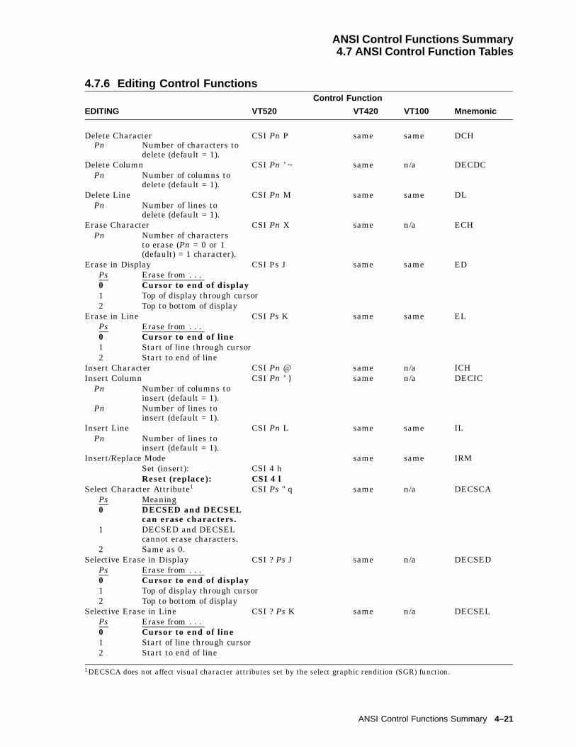
ANSI Control Functions Summary4.7 ANSI Control Function Tables
4.7.6 Editing Control FunctionsControl Function
EDITING VT520 VT420 VT100 Mnemonic
Delete Character CSI Pn P same same DCHPn Number of characters to
delete (default = 1).Delete Column CSI Pn ’ ~ same n/a DECDC
Pn Number of columns todelete (default = 1).
Delete Line CSI Pn M same same DLPn Number of lines to
delete (default = 1).Erase Character CSI Pn X same n/a ECH
Pn Number of charactersto erase (Pn = 0 or 1(default) = 1 character).
Erase in Display CSI Ps J same same EDPs Erase from . . .0 Cursor to end of display1 Top of display through cursor2 Top to bottom of display
Erase in Line CSI Ps K same same ELPs Erase from . . .0 Cursor to end of line1 Start of line through cursor2 Start to end of line
Insert Character CSI Pn @ same n/a ICHInsert Column CSI Pn ’ } same n/a DECIC
Pn Number of columns toinsert (default = 1).
Pn Number of lines toinsert (default = 1).
Insert Line CSI Pn L same same ILPn Number of lines to
insert (default = 1).Insert/Replace Mode same same IRM
Set (insert): CSI 4 hReset (replace): CSI 4 l
Select Character Attribute1 CSI Ps " q same n/a DECSCAPs Meaning0 DECSED and DECSEL
can erase characters.1 DECSED and DECSEL
cannot erase characters.2 Same as 0.
Selective Erase in Display CSI ? Ps J same n/a DECSEDPs Erase from . . .0 Cursor to end of display1 Top of display through cursor2 Top to bottom of display
Selective Erase in Line CSI ? Ps K same n/a DECSELPs Erase from . . .0 Cursor to end of line1 Start of line through cursor2 Start to end of line
1DECSCA does not affect visual character attributes set by the select graphic rendition (SGR) function.
ANSI Control Functions Summary 4–21
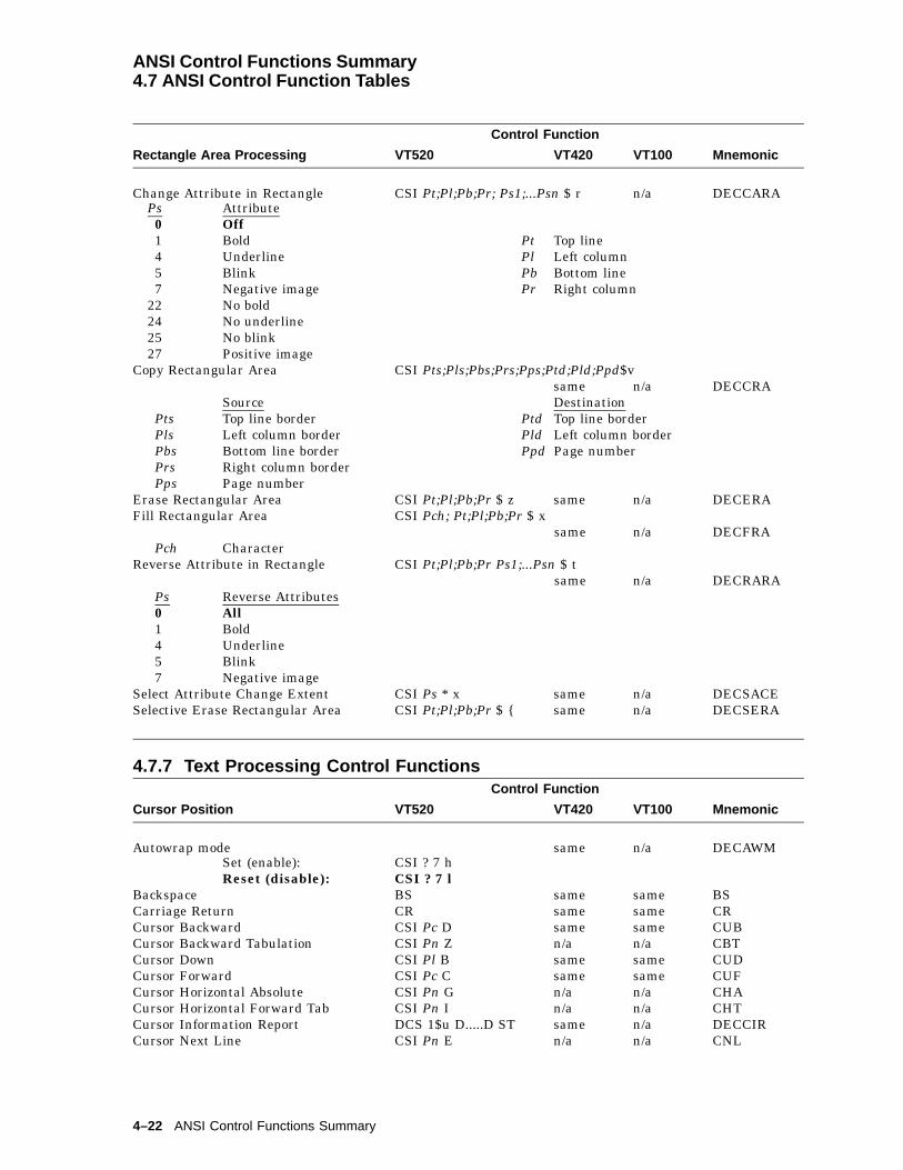
ANSI Control Functions Summary4.7 ANSI Control Function Tables
Control Function
Rectangle Area Processing VT520 VT420 VT100 Mnemonic
Change Attribute in Rectangle CSI Pt;Pl;Pb;Pr; Ps1;...Psn $ r n/a DECCARAPs Attribute0 Off1 Bold Pt Top line4 Underline Pl Left column5 Blink Pb Bottom line7 Negative image Pr Right column
22 No bold24 No underline25 No blink27 Positive image
Copy Rectangular Area CSI Pts;Pls;Pbs;Prs;Pps;Ptd;Pld;Ppd$vsame n/a DECCRA
Source DestinationPts Top line border Ptd Top line borderPls Left column border Pld Left column borderPbs Bottom line border Ppd Page numberPrs Right column borderPps Page number
Erase Rectangular Area CSI Pt;Pl;Pb;Pr $ z same n/a DECERAFill Rectangular Area CSI Pch; Pt;Pl;Pb;Pr $ x
same n/a DECFRAPch Character
Reverse Attribute in Rectangle CSI Pt;Pl;Pb;Pr Ps1;...Psn $ tsame n/a DECRARA
Ps Reverse Attributes0 All1 Bold4 Underline5 Blink7 Negative image
Select Attribute Change Extent CSI Ps * x same n/a DECSACESelective Erase Rectangular Area CSI Pt;Pl;Pb;Pr $ { same n/a DECSERA
4.7.7 Text Processing Control FunctionsControl Function
Cursor Position VT520 VT420 VT100 Mnemonic
Autowrap mode same n/a DECAWMSet (enable): CSI ? 7 hReset (disable): CSI ? 7 l
Backspace BS same same BSCarriage Return CR same same CRCursor Backward CSI Pc D same same CUBCursor Backward Tabulation CSI Pn Z n/a n/a CBTCursor Down CSI Pl B same same CUDCursor Forward CSI Pc C same same CUFCursor Horizontal Absolute CSI Pn G n/a n/a CHACursor Horizontal Forward Tab CSI Pn I n/a n/a CHTCursor Information Report DCS 1$u D.....D ST same n/a DECCIRCursor Next Line CSI Pn E n/a n/a CNL
4–22 ANSI Control Functions Summary
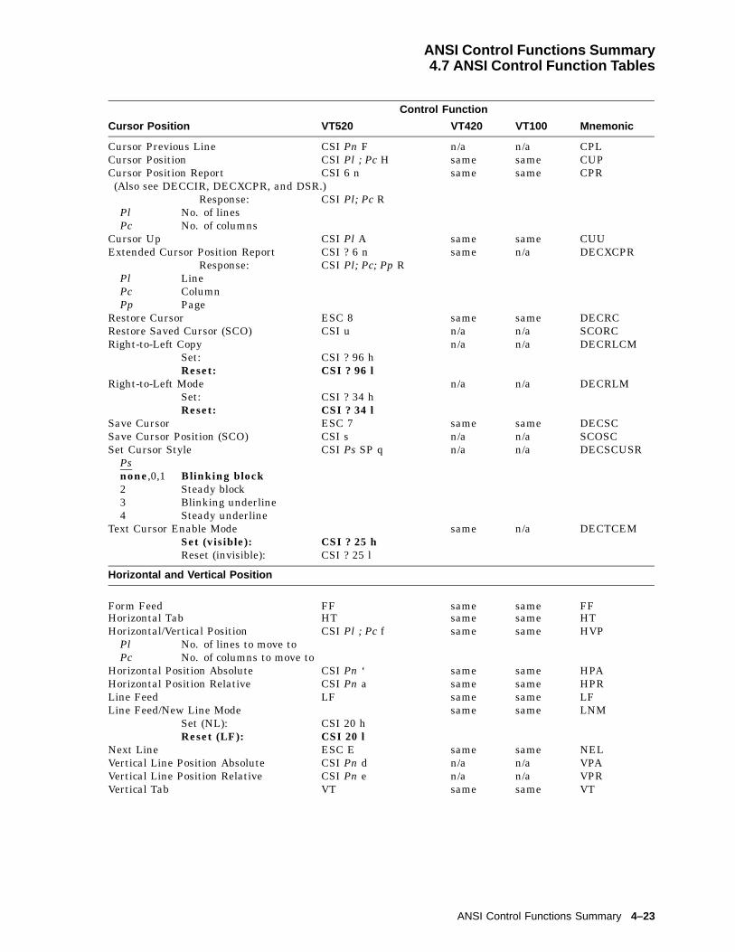
ANSI Control Functions Summary4.7 ANSI Control Function Tables
Control Function
Cursor Position VT520 VT420 VT100 Mnemonic
Cursor Previous Line CSI Pn F n/a n/a CPLCursor Position CSI Pl ; Pc H same same CUPCursor Position Report CSI 6 n same same CPR(Also see DECCIR, DECXCPR, and DSR.)
Response: CSI Pl; Pc RPl No. of linesPc No. of columns
Cursor Up CSI Pl A same same CUUExtended Cursor Position Report CSI ? 6 n same n/a DECXCPR
Response: CSI Pl; Pc; Pp RPl LinePc ColumnPp Page
Restore Cursor ESC 8 same same DECRCRestore Saved Cursor (SCO) CSI u n/a n/a SCORCRight-to-Left Copy n/a n/a DECRLCM
Set: CSI ? 96 hReset: CSI ? 96 l
Right-to-Left Mode n/a n/a DECRLMSet: CSI ? 34 hReset: CSI ? 34 l
Save Cursor ESC 7 same same DECSCSave Cursor Position (SCO) CSI s n/a n/a SCOSCSet Cursor Style CSI Ps SP q n/a n/a DECSCUSR
Psnone,0,1 Blinking block2 Steady block3 Blinking underline4 Steady underline
Text Cursor Enable Mode same n/a DECTCEMSet (visible): CSI ? 25 hReset (invisible): CSI ? 25 l
Horizontal and Vertical Position
Form Feed FF same same FFHorizontal Tab HT same same HTHorizontal/Vertical Position CSI Pl ; Pc f same same HVP
Pl No. of lines to move toPc No. of columns to move to
Horizontal Position Absolute CSI Pn ‘ same same HPAHorizontal Position Relative CSI Pn a same same HPRLine Feed LF same same LFLine Feed/New Line Mode same same LNM
Set (NL): CSI 20 hReset (LF): CSI 20 l
Next Line ESC E same same NELVertical Line Position Absolute CSI Pn d n/a n/a VPAVertical Line Position Relative CSI Pn e n/a n/a VPRVertical Tab VT same same VT
ANSI Control Functions Summary 4–23

ANSI Control Functions Summary4.7 ANSI Control Function Tables
Control Function
Horizontal Tabs—Set/Clear VT520 VT420 VT100 Mnemonic
Set Horizontal Tab ESC H same same HTSSet Tab at every 8 columns CSI ? 5 W n/a n/a DECST8CClear Tabs CSI Ps g same same TBCPs Clear . . .none, 0 tab at cursor3 all tabs
Margins and Scrolling
Back Index ESC 6 same n/a DECBIForward Index ESC 9 same n/a DECFIIndex ESC D same same INDOrigin Mode same same DECOM
Set (in margins): CSI ? 6 hReset (upper-left): CSI ? 6 l
Reverse Index ESC M same same RIScrolling Mode same same DECSCLM
Set (smooth): CSI ? 4 hReset (jump): CSI ? 4 l
Set Scroll Speed CSI Ps SP p n/a n/a DECSSCLSPs
none, 0,1, 2, 3
Smooth 2
4, 5, 6,7, 8
Smooth 4 DECSCLM
9 JumpLeft Right Margin Mode same n/a DECLRMM
Set (enable): CSI 69 hReset (disable): CSI 69 l
Set Left and Right Margin CSI Pl ; Pr s same same DECSLRMPl Left column margin
(default = 1)Pr Right column margin
(default = 80 or 132,depending on page width)
Set Top and Bottom Margin CSI Pt ; Pb r same same DECSTBMPt Top margin (default = 1)Pb Bottom margin
Page Arrangement and Size 1
Column Mode same same DECCOLMSet (132 columns): CSI ? 3 hReset (80 columns): CSI ? 3 l
No clear screen on column change n/a n/a DECNCSMDo not clear: CSI ? 95 hClear screen: CSI ? 95 l
Select Columns per Page CSI Ps $ | same n/a DECSCPPPs Set each page to . . .0 or 80 80 columns132 132 columns
Set Lines Per Page CSI Pn t same same DECSLPP
1The page size can be 24, 25, 36, 42, 48, 52, and 72 lines with 80 or 132 columns.
4–24 ANSI Control Functions Summary
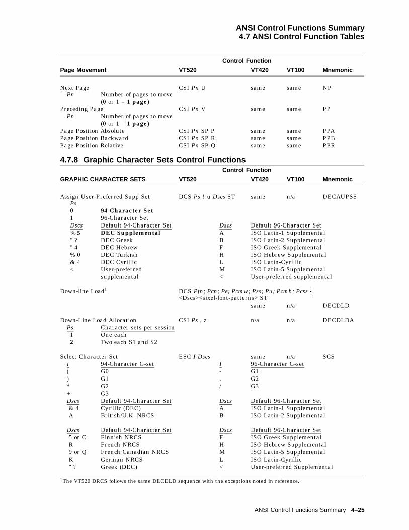
ANSI Control Functions Summary4.7 ANSI Control Function Tables
Control Function
Page Movement VT520 VT420 VT100 Mnemonic
Next Page CSI Pn U same same NPPn Number of pages to move
(0 or 1 = 1 page)Preceding Page CSI Pn V same same PP
Pn Number of pages to move(0 or 1 = 1 page)
Page Position Absolute CSI Pn SP P same same PPAPage Position Backward CSI Pn SP R same same PPBPage Position Relative CSI Pn SP Q same same PPR
4.7.8 Graphic Character Sets Control FunctionsControl Function
GRAPHIC CHARACTER SETS VT520 VT420 VT100 Mnemonic
Assign User-Preferred Supp Set DCS Ps ! u Dscs ST same n/a DECAUPSSPs0 94-Character Set1 96-Character SetDscs Default 94-Character Set Dscs Default 96-Character Set% 5 DEC Supplemental A ISO Latin-1 Supplemental" ? DEC Greek B ISO Latin-2 Supplemental" 4 DEC Hebrew F ISO Greek Supplemental% 0 DEC Turkish H ISO Hebrew Supplemental& 4 DEC Cyrillic L ISO Latin-Cyrillic< User-preferred M ISO Latin-5 Supplemental
supplemental < User-preferred supplemental
Down-line Load1 DCS Pfn; Pcn; Pe; Pcmw; Pss; Pu; Pcmh; Pcss f<Dscs><sixel-font-patterns> ST
same n/a DECDLD
Down-Line Load Allocation CSI Ps , z n/a n/a DECDLDAPs Character sets per session1 One each2 Two each S1 and S2
Select Character Set ESC I Dscs same n/a SCSI 94-Character G-set I 96-Character G-set( G0 - G1) G1 . G2* G2 / G3+ G3Dscs Default 94-Character Set Dscs Default 96-Character Set& 4 Cyrillic (DEC) A ISO Latin-1 SupplementalA British/U.K. NRCS B ISO Latin-2 Supplemental
Dscs Default 94-Character Set Dscs Default 96-Character Set5 or C Finnish NRCS F ISO Greek SupplementalR French NRCS H ISO Hebrew Supplemental9 or Q French Canadian NRCS M ISO Latin-5 SupplementalK German NRCS L ISO Latin-Cyrillic" ? Greek (DEC) < User-preferred Supplemental
1The VT520 DRCS follows the same DECDLD sequence with the exceptions noted in reference.
ANSI Control Functions Summary 4–25
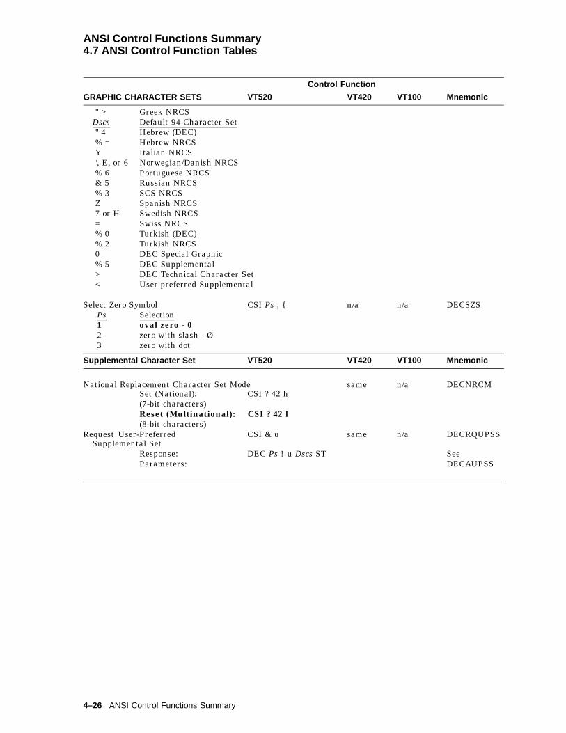
ANSI Control Functions Summary4.7 ANSI Control Function Tables
Control Function
GRAPHIC CHARACTER SETS VT520 VT420 VT100 Mnemonic
" > Greek NRCSDscs Default 94-Character Set" 4 Hebrew (DEC)% = Hebrew NRCSY Italian NRCS‘, E, or 6 Norwegian/Danish NRCS% 6 Portuguese NRCS& 5 Russian NRCS% 3 SCS NRCSZ Spanish NRCS7 or H Swedish NRCS= Swiss NRCS% 0 Turkish (DEC)% 2 Turkish NRCS0 DEC Special Graphic% 5 DEC Supplemental> DEC Technical Character Set< User-preferred Supplemental
Select Zero Symbol CSI Ps , { n/a n/a DECSZSPs Selection1 oval zero - 02 zero with slash - Ø3 zero with dot
Supplemental Character Set VT520 VT420 VT100 Mnemonic
National Replacement Character Set Mode same n/a DECNRCMSet (National): CSI ? 42 h(7-bit characters)Reset (Multinational): CSI ? 42 l(8-bit characters)
Request User-PreferredSupplemental Set
CSI & u same n/a DECRQUPSS
Response: DEC Ps ! u Dscs ST SeeParameters: DECAUPSS
4–26 ANSI Control Functions Summary
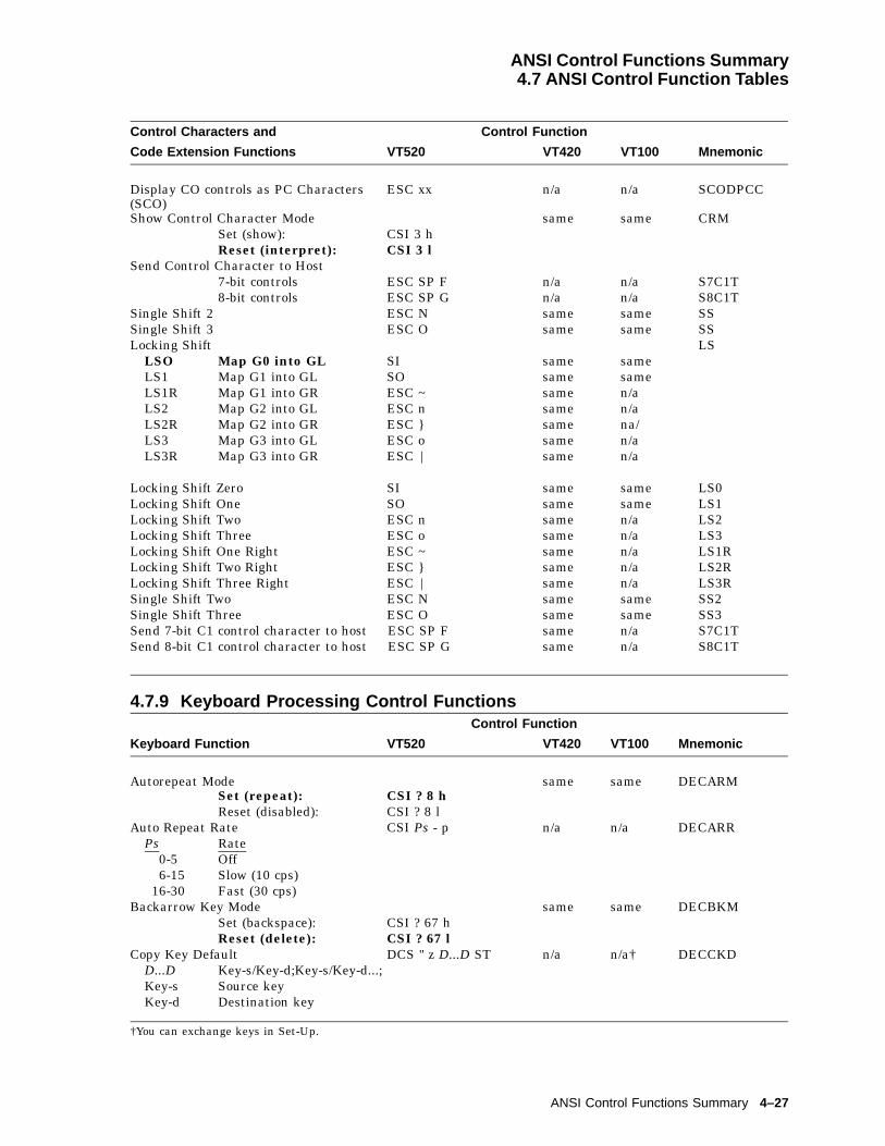
ANSI Control Functions Summary4.7 ANSI Control Function Tables
Control Characters and Control Function
Code Extension Functions VT520 VT420 VT100 Mnemonic
Display CO controls as PC Characters(SCO)
ESC xx n/a n/a SCODPCC
Show Control Character Mode same same CRMSet (show): CSI 3 hReset (interpret): CSI 3 l
Send Control Character to Host7-bit controls ESC SP F n/a n/a S7C1T8-bit controls ESC SP G n/a n/a S8C1T
Single Shift 2 ESC N same same SSSingle Shift 3 ESC O same same SSLocking Shift LS
LSO Map G0 into GL SI same sameLS1 Map G1 into GL SO same sameLS1R Map G1 into GR ESC ~ same n/aLS2 Map G2 into GL ESC n same n/aLS2R Map G2 into GR ESC } same na/LS3 Map G3 into GL ESC o same n/aLS3R Map G3 into GR ESC | same n/a
Locking Shift Zero SI same same LS0Locking Shift One SO same same LS1Locking Shift Two ESC n same n/a LS2Locking Shift Three ESC o same n/a LS3Locking Shift One Right ESC ~ same n/a LS1RLocking Shift Two Right ESC } same n/a LS2RLocking Shift Three Right ESC | same n/a LS3RSingle Shift Two ESC N same same SS2Single Shift Three ESC O same same SS3Send 7-bit C1 control character to host ESC SP F same n/a S7C1TSend 8-bit C1 control character to host ESC SP G same n/a S8C1T
4.7.9 Keyboard Processing Control FunctionsControl Function
Keyboard Function VT520 VT420 VT100 Mnemonic
Autorepeat Mode same same DECARMSet (repeat): CSI ? 8 hReset (disabled): CSI ? 8 l
Auto Repeat Rate CSI Ps - p n/a n/a DECARRPs Rate
0-5 Off6-15 Slow (10 cps)
16-30 Fast (30 cps)Backarrow Key Mode same same DECBKM
Set (backspace): CSI ? 67 hReset (delete): CSI ? 67 l
Copy Key Default DCS " z D...D ST n/a n/a† DECCKDD...D Key-s/Key-d;Key-s/Key-d...;Key-s Source keyKey-d Destination key
†You can exchange keys in Set-Up.
ANSI Control Functions Summary 4–27

ANSI Control Functions Summary4.7 ANSI Control Function Tables
Control Function
Keyboard Function VT520 VT420 VT100 Mnemonic
Cursor Keys Mode same same DECCKMSet (application): CSI ? 1 hReset (cursor): CSI ? 1 l
Define Function Key (SCO) ESC Q Fn string n/a n/a SCODFKDevice Status Report (keyboard status) DSR
Request Keyboard Report: CSI ? 26 n same sameReply to Keyboard Request: CSI ? 27 ; Pn; Pst; Ptyp n
same samePn Keyboard Language (VT/PC) Pn Keyboard Language (VT or PC)0 Unknown 15 Spanish1 North American 16 Portuguese2 British 19 Hebrew3 Belgian (Flemish) 22 Greek4 French Canadian 28 Canadian English5 Danish 29 Turkish Q/Turkish6 Finnish 30 Turkish F/Turkish7 German/German 31 Hungarian8 Dutch 33 Slovak9 Italian 34 Czech
10 Swiss French 35 Polish11 Swiss German 36 Romanian12 Swedish 38 SCS13 Norwegian 39 Russian14 French 40 Latin AmericanPst Keyboard Status Ptyp Keyboard Type0 Keyboard Ready 4 LK4113 No Keyboard 5 PCXAL8 Keyboard Busy
Extended Keyboard Report APC : ppp mm ST same n/a DECEKBDEnable Local Functions CSI Pf1;Pc1;...Pfn;Pcn + q n/a DECELFEnable Secondary Keyboard
Language Modesame n/a DECESKM
Set (secondary): CSI ? 104 hReset (primary): CSI ? 104 l
Hebrew Encoding Mode1 same n/a DECHEMSet (8-bit char): CSI ? 36 hReset (7-bit char): CSI ? 36 l
Hebrew Keyboard Map Mode same n/a DECHEBMSet (Hebrew keyboard): CSI ? 35 hReset (NorthAmerican):
CSI ? 35 l
Keyboard Action Mode same same KAMSet (lock): CSI 2 hReset (unlock): CSI 2 l
Keypad Application Mode ESC = same same DECKPAM
Keyboard Language Selection CSI Ps1; Ps2 SP g same n/a DECKBDPs1 Keyboard Type1,0 DEC keyboard layout2 Enhanced PC keyboard layout
1 DECHEM is opposite in action to DECNRCM; that is, setting DECHEM has the same result as resetting DECNRCM.
4–28 ANSI Control Functions Summary

ANSI Control Functions Summary4.7 ANSI Control Function Tables
Control Function
Keyboard Function VT520 VT420 VT100 Mnemonic
Ps2 Keyboard Language (VT/PC) Ps2 Keyboard Language (VT or PC)none, North American 15 Spanish0 or 1 16 Portuguese2 British 19 Hebrew3 Belgian 22 Greek4 French Canadian 28 Canadian English5 Danish 29 Turkish Q/Turkish6 Finnish 30 Turkish F/Turkish7 German 31 Hungarian8 Dutch 33 Slovak9 Italian 34 Czech
10 Swiss French 35 Polish11 Swiss German 36 Romanian12 Swedish 38 SCS13 Norwegian 39 Russian14 French 40 Latin American
Keypad Numeric Mode ESC > same same DECKPNMKey Position Mode same n/a DECKPM
Set (key position): CSI ? 81 hReset (char codes): CSI ? 81 l
Keyboard Usage Mode same n/a DECKBUMSet (data processing): CSI ? 68 hReset (typewriter): CSI ? 68 l
Local Function Key Control CSI Pk1; Pf1; Pk2; Pf2...*gsame n/a DECLFKC
Pk Function VT Keyboard Enhanced PC Keyboard1 Hold F1 Scroll Lock2 Print F2 Print Screen3 Set-Up F3 Cap Lock/Print Screen
North American/Greek Selection same n/a DECNAKBSet (North American): CSI ? 57 hReset (Greek keyboard): CSI ? 57 l
Numeric Keypad Mode same n/a DECNKMSet (application): CSI ? 66 hReset (numeric): CSI ? 66 l
ANSI Control Functions Summary 4–29
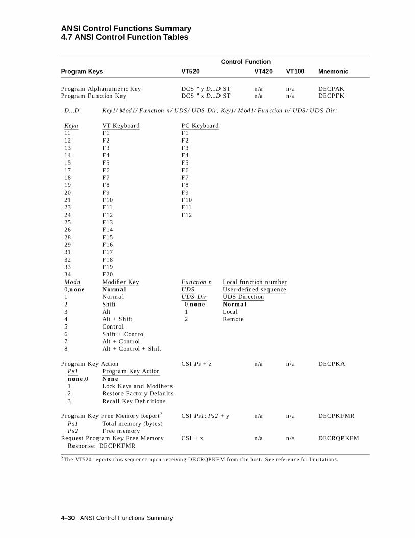
ANSI Control Functions Summary4.7 ANSI Control Function Tables
Control Function
Program Keys VT520 VT420 VT100 Mnemonic
Program Alphanumeric Key DCS " y D...D ST n/a n/a DECPAKProgram Function Key DCS " x D...D ST n/a n/a DECPFK
D...D Key1/Mod1/Function n/UDS/UDS Dir; Key1/Mod1/Function n/UDS/UDS Dir;
Keyn VT Keyboard PC Keyboard11 F1 F112 F2 F213 F3 F314 F4 F415 F5 F517 F6 F618 F7 F719 F8 F820 F9 F921 F10 F1023 F11 F1124 F12 F1225 F1326 F1428 F1529 F1631 F1732 F1833 F1934 F20Modn Modifier Key Function n Local function number0,none Normal UDS User-defined sequence1 Normal UDS Dir UDS Direction2 Shift 0,none Normal3 Alt 1 Local4 Alt + Shift 2 Remote5 Control6 Shift + Control7 Alt + Control8 Alt + Control + Shift
Program Key Action CSI Ps + z n/a n/a DECPKAPs1 Program Key Actionnone,0 None1 Lock Keys and Modifiers2 Restore Factory Defaults3 Recall Key Definitions
Program Key Free Memory Report2 CSI Ps1; Ps2 + y n/a n/a DECPKFMRPs1 Total memory (bytes)Ps2 Free memory
Request Program Key Free Memory CSI + x n/a n/a DECRQPKFMResponse: DECPKFMR
2The VT520 reports this sequence upon receiving DECRQPKFM from the host. See reference for limitations.
4–30 ANSI Control Functions Summary
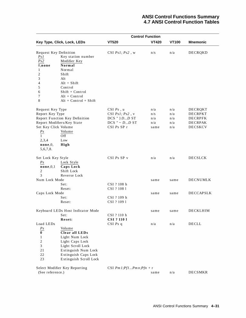
ANSI Control Functions Summary4.7 ANSI Control Function Tables
Control Function
Key Type, Click, Lock, LEDs VT520 VT420 VT100 Mnemonic
Request Key Definition CSI Ps1; Ps2 , w n/s n/a DECRQKDPs1 Key station numberPs2 Modifier Key0,none Normal1 Normal2 Shift3 Alt4 Alt + Shift5 Control6 Shift + Control7 Alt + Control8 Alt + Control + Shift
Request Key Type CSI Ps , u n/a n/a DECRQKTReport Key Type CSI Ps1; Ps2 , v n/s n/a DECRPKTReport Function Key Definition DCS " } D...D ST n/a n/a DECRPFKReport Modifiers/Key State DCS " ~ D...D ST n/a n/a DECRPAKSet Key Click Volume CSI Ps SP r same n/a DECSKCV
Ps Volume1 Off2,3,4 Lownone,0, High5,6,7,8.
Set Lock Key Style CSI Ps SP v n/a n/a DECSLCKPs Lock Stylenone,0,1 Caps Lock2 Shift Lock3 Reverse Lock
Num Lock Mode same same DECNUMLKSet: CSI ? 108 hReset: CSI ? 108 l
Caps Lock Mode same same DECCAPSLKSet: CSI ? 109 hReset: CSI ? 109 l
Keyboard LEDs Host Indicator Mode same same DECKLHIMSet: CSI ? 110 hReset: CSI ? 110 l
Load LEDs CSI Ps q n/a n/a DECLLPs Volume0 Clear all LEDs1 Light Num Lock2 Light Caps Lock3 Light Scroll Lock21 Extinguish Num Lock22 Extinguish Caps Lock23 Extinguish Scroll Lock
Select Modifier Key Reporting CSI Pm1;Pf1...Pmn;Pfn + r(See reference.) same n/a DECSMKR
ANSI Control Functions Summary 4–31

ANSI Control Functions Summary4.7 ANSI Control Function Tables
Control Function
User-Defined Keys VT520 VT420 VT100 Mnemonic
User Defined Keys DCS Ps1; Ps2; Ps3 | D...D STsame n/a DECUDK3
Ps1 Clear . . .none,0 All UDKs before loading new values1 Old UDKs only when redefined; load new UDK values.Ps2 Lock . . .none,0 UDKs against future redefinition1 Don’t lock the UDKs against future redefinition.Ps3 Define . . .none, 0 Shifted function key1 Unshifted function key2 Shifted function key3 Alt unshifted function key4 Alt shifted function keyD...D Key1/St1/Dir;Key2/St2/Dir;.......Keyn/Stn/Dir;Stn Sequence user-defined key (UDK)Keyn VT Keyboard PC Keyboard11 F1 F112 F2 F213 F3 F314 F4 F415 F5 F517 F6 F618 F7 F719 F8 F820 F9 F921 F10 F1023 F11 F1124 F12 F1225 F1326 F1428 F1529 F1631 F1732 F1833 F1934 F20Dir Direction4
0,none Normal1 Local2 Remote
DSR - User-Defined Key Request same n/a DSR-UDKRequest UDK lock: CSI ? 25 nReply to UDK locked status: CSI ? 20 nReply to UDK unlocked status: CSI ? 21 n
3CAUTION: Local Function keys may be disabled by redefining them with DECUDK.4See DECPFK for direction definitions.
4–32 ANSI Control Functions Summary
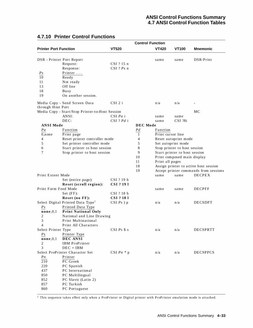
ANSI Control Functions Summary4.7 ANSI Control Function Tables
4.7.10 Printer Control FunctionsControl Function
Printer Port Function VT520 VT420 VT100 Mnemonic
DSR - Printer Port Report same same DSR-PrintRequest: CSI ? 15 nResponse: CSI ? Ps n
Ps Printer . . .10 Ready11 Not ready13 Off line18 Busy19 On another session.
Media Copy - Send Screen Datathrough Host Port
CSI 2 i n/a n/a -
Media Copy - Start/Stop Printer-to-Host Session MCANSI: CSI Pa i same sameDEC: CSI ? Pd i same CSI ?8i
ANSI Mode DEC ModePa Function Pd Function0,none Print page 1 Print cursor line4 Reset printer controller mode 4 Reset autoprint mode5 Set printer controller mode 5 Set autoprint mode6 Start printer to host session 8 Stop printer to host session7 Stop printer to host session 9 Start printer to host session
10 Print composed main display11 Print all pages18 Assign printer to active host session19 Accept printer commands from sessions
Print Extent Mode same same DECPEXSet (entire page): CSI ? 19 hReset (scroll region): CSI ? 19 l
Print Form Feed Mode same same DECPFFSet (FF): CSI ? 18 hReset (no FF): CSI ? 18 l
Select Digital Printed Data Type1 CSI Ps ) p n/a n/a DECSDPTPs Printed Data Typenone,0,1 Print National Only2 National and Line Drawing3 Print Multinational4 Print All Characters
Select Printer Type CSI Ps $ s n/a n/a DECSPRTTPs Printer Typenone,0,1 DEC ANSI2 IBM ProPrinter3 DEC + IBM
Select ProPrinter Character Set CSI Pn * p n/a n/a DECSPPCSPn Printer210 PC Greek220 PC Spanish437 PC International850 PC Multilingual852 PC Slavic (Latin 2)857 PC Turkish860 PC Portuguese
1 This sequence takes effect only when a ProPrinter or Digital printer with ProPrinter emulation mode is attached.
ANSI Control Functions Summary 4–33

ANSI Control Functions Summary4.7 ANSI Control Function Tables
862 PC Hebrew863 PC French-Canadian865 PC Danish/Norwegian866 PC Cyrillic
Start/stop printer; see Media Copy.
DEC Printers with ProPrinter Emulation
Enter/Return from IBM ProPrinter Emulation Mode n/a n/a DECIPEMEnter: CSI ? 58 hReturn: CSI ? 58 l
4.7.11 Terminal Management Control FunctionsControl Function
Desktop Feature VT520 VT420 VT100 Mnemonic
Select Set-Up Language CSI Ps p n/a n/a DECSSLPsnone,0,1 English2 French3 German4 Spanish5 Italian
Load Time of Day CSI Ps1; Ps2 , p n/a n/a DECLTODPs1 Hour (decimal number
between 00 and 23)Ps2 Minutes (decimal
number between00 and 59)
CRT/Energy Saver Functions
CRT Save Mode n/a n/a DECCRTSMSet (enable CRT saver 15 min): CSI 97 hReset (disable CRT saver): CSI 97 l
CRT Saver Timing CSI Ps - q n/a n/a DECCRTSTPs Selection0 Never5 5 min
15 15 min30 30 min60 60 min
Energy Saver Timing CSI Ps - r n/a n/a DECSESTPs Selection0 Never5 5 min
15 15 min30 30 min
Host Wake-Up mode(CRT and Energy saver)
same same DECHWUM
Set: CSI ? 113 hReset: CSI ? 113 l
4–34 ANSI Control Functions Summary

ANSI Control Functions Summary4.7 ANSI Control Function Tables
Control Function
Device Attributes VT520 VT420 VT100 Mnemonic
Device Attributes orPrimary Device Attributes
CSI c or CSI 0 c same same DA1
Model Response- CSI ? Psc ; PS1 ; ... Psn cVT520 CSI ? 65;1;2;7;8;9;12;18;19;21;23;24;42;44;45;46 cVT525 CSI ? 65;1;2;7;9;12;18;19;21;22;23;24;42;44;45;46 c
Ext Description Ext Description1 132 columns 18 Windowing capability2 Printer port extension 21 Horizontal scrolling6 Selective erase 23 Greek extension7 DRCS 24 Turkish extension8 UDK 42 ISO Latin-2 character set9 NRCS 44 VT PCTerm
12 Serbo-Croatian (SCS) 45 Soft key mapping15 Technical character set 46 ASCII terminal emulation
Secondary Device Attributes CSI > c or CSI > 0 c same n/a DA2Keyboard ResponseVT520 VT keyboard CSI > 64; Pv; 0 cVT525 VT keyboard CSI > 65; Pv; 0 cVT520 PC keyboard CSI > 64; Pv; 1 cVT525 PC keyboard CSI > 65; Pv; 1 c
Tertiary Device Attributes CSI = c or CSI = 0 c same same DA3
Terminal ID
Identify Device ESC Z n/a same DECID1
Report Terminal Unit ID DCS ! | D...D ST same n/a DECRPTUIPv Firmware version
Select Terminal ID2 CSI Ps , q same same DECTIDPs ID Type Response Terminal Type0 VT100 ESC [ ? 1; 2 c VT1001 VT101 ESC [ ? 1; 0 c VT1012 VT102 ESC [ ? 6 c VT1025 VT220 CSI ? 62; 1; 2; 7; 8 c VT220 North American
CSI ? 62; 1; 2; 7; 8; 9 c VT220 International7 VT320 CSI ? 63; 1; 2; 7; 8 c VT320 North American
CSI ? 63; 1; 2; 7; 8; 9 c VT320 International9 VT420 CSI ? 64; 1; 2; 7; 8; 9; 15; 18; 21 c VT420 North American
CSI ? 64; 1; 2; 7; 8; 9; 15; 18; 21 c VT420 International10 VT520/VT525 Refer to DA1 for response.
Set Terminal Unit ID DCS ! f D...D ST n/a n/a DECSTUI
1DECID may not be supported; use primary device attributes (DA1) instead.2DECTID has no effect when the terminal is in VT52 mode.
ANSI Control Functions Summary 4–35

ANSI Control Functions Summary4.7 ANSI Control Function Tables
Control Function
Terminal Modes VT520 VT420 VT100 Mnemonic
Enter/Exit VT PCTerm Mode orselect ASCII characters or scancodes
CSI ? Ps1; Ps2 r same n/a DECPCTERM
Ps1 VT Emulation Mode SCO Console Modenone, 0 VT Mode ASCII characters1 VT PCTerm Mode ScancodesPs2 Character Set Ps2 Character Set210 PC Greek none,0 No Change220 PC Spanish 1 PC Multilingual437 PC International 2 PC International850 PC Multilingual 3 PC Danish/Norwegian852 PC Slavic (Latin 2) 4 PC Spanish857 PC Turkish 5 PC Portuguese860 PC Portuguese 6 DEC Supplemental862 PC Hebrew 7 ISO Latin 1863 PC French-Canadian865 PC Danish866 PC Cyrillic
Exit ANSI (VT52) Mode ESC < same same DECANMOverscan Mode3 n/a n/a DECOSCNM
Set (enable overscan): CSI ? 106 hReset (disable overscan): CSI ? 106 l
Select Conformance (Operating) Level CSI 6 Ps1 ; Ps2 ; " p same same DECSCLPs1 Level Selected Ps2 Data Bitsnone,0,1 1 - VT100 none, 0, 2 8-bit controls2,3,4,5 5 - VT520/VT525 1 7-bit controlsPs Cursor Style1 50 Hz2 60 Hznone0 or 3
� 70 Hz
Show Control Character Mode same same CRMSet (show): CSI 3 hReset (interpret): CSI 3 l
Terminal Mode Emulation CSI Ps SP ~ n/a n/a DECTMEPs Terminal Mode1 VT520/VT525 (VT Level 5)2 VT1003 VT524 VT PCTerm5 WYSE 160/606 WYSE PCTerm7 WYSE 50/50+8 WYSE 150/1209 TVI 950
10 TVI 92511 TVI 910+12 ADDS A213 SCO Console14 WYSE 325
Set Mode CSI P1.....Pn h same same SM
3The VT525 and VGB25 models do not have overscan.
4–36 ANSI Control Functions Summary

ANSI Control Functions Summary4.7 ANSI Control Function Tables
Mode Description ANSI Mode DEC ModePa Mnemonic4 Pd Mnemonic Mode
Guarded area transfer 1 GATM * ?1 DECCKM Cursor keysKeyboard action 2 KAM ?2 DECANM ANSIControl representation 3 CRM ?3 DECCOLMColumnInsert/replace 4 IRM ?4 DECSCLMScrollingStatus reporting transfer 5 SRTM * ?5 DECSCNMScreen
?6 DECOM OriginVertical editing 7 VEM * ?7 DECAWM AutowrapHoriz editing 10 HEM * ?8 DECARM AutorepeatPositioning unit 11 PUM *Send/receive 12 SRMFormat effector action 13 FEAM *Format effector transfer 14 FETM *Multiple area transfer 15 MATM *Transfer termination 16 TTM *Selected area transfer 17 SATM *Tabulation stop 18 TSM * ?18 DECPFF Print formEditing boundary 19 EBM * ?19 DECPEX Print extentLinefeed/New line 20 LNMText cursor enable ?25 DECTCEMRight-to-left ?34 DECRLMHebrew keyboard map ?35 DECHEBMHebrew encoding ?36 DECHCEMNRCS characters ?42 DECNRCMGreek/N.A. ?57 DECNAKBHoriz cursor coupling ?60 DECHCCM *Vertical cursor coupling ?61 DECVCCMPage cursor coupling ?64 DECPCCMNumeric keypad ?66 DECNKMBackarrow key ?67 DECBKMKeyboard usage ?68 DECKBUMVertical split screen ?69 DECVSSMTransmit rate limiting ?73 DECXRLMMNo clear screen ?95 DECNCSMRight-to-left copy ?96 DECRLCMCRT save ?97 DECCRTSMAuto resize ?98 DECARSMModem control ?99 DECMCMAuto answerback ?100 DECAAMConceal answerback ?101 DECCANSMNull ?102 DECNULMHalf-duplex ?103 DECHDPXMEnable secondary keyboard language ?104 DECESKMOverscan ?106 DECOSCNMFramed windows mode ?111 DECFWMReview previous lines ?112 DECRPLHost Wake-Up ?113 DECHWUMAlternate text color underline ?114 DECATCUMAlternate text color blink ?115 DECATCBMBold and blink style mode ?116 DECBBSMErase color mode ?117 DECECM
4The * means this mode is always Reset in the terminal and cannot be changed.
ANSI Control Functions Summary 4–37

ANSI Control Functions Summary4.7 ANSI Control Function Tables
Control Function
Terminal Modes VT520 VT420 VT100 Mnemonic
Report Mode (ANSI) CSI Pa; Ps $ y same n/a DECRPMor (DEC) CSI ? Pd; Ps $ y same n/a
Reset Mode CSI P1.....Pn l same same RMSet/Reset Parameters ANSI Mode DEC Mode
PsNot recognized 0 sameSet 1 sameReset 2 sameSet permanently 3 sameReset permanently 4 same
Set Mode/Reset Mode (See also DECRQM.) SM/RMSend/Receive Mode (Local Echo) same same SRM
Set (Local echo off): CSI 12 hReset (Local echo on): CSI 12 l
Tests
Invoke Confidence Test5 CSI 4 ; Ps ; ... ; Ps y same n/a DECTST6
Ps Test0 "All Tests" (1,2,3,6)1 Power-Up Self Test2 RS-232 Port Data Loopback3 Printer Port Loopback4 Speed Select and Indicator5 Reserved - No action6 Modem Loopback Test7 EIA-423 Port Loopback8 Parallel Port Loopback9 Repeat other tests
Messages
Auto Answerback Mode same same DECAAMSet: CSI ? 100 hReset: CSI ? 100 l
Conceal Answerback Message Mode n/a n/a DECCANSMSet: CSI ? 101 hReset: CSI ? 101 l
Load Answerback Message DCS Ps v D...D ST n/a n/a DECLANSLoad Banner Message DCS Ps r D...D ST n/a n/a DECLBAN
Ps1 Printer Port1 Parallel port2 Comm13 Comm2Ps2 Session 11 Comm12 Comm2
5‘‘ESC # 8’’ invokes the Screen Alignment test (all Es).6DECTST causes a disconnect; therefore, it should not be used in conjunction with a modem.
4–38 ANSI Control Functions Summary

ANSI Control Functions Summary4.7 ANSI Control Function Tables
Control Function
Reset Terminal VT520 VT420 VT100 Mnemonic
Reset to Initial state ESC c same same RISSecure Reset ESC [ Pr + p same n/a DECSRSecure Reset Confirmation ESC [ Pr * q same same DECSRCSoft Terminal Reset CSI ! p same n/a DECSTR
Terminal Status Display
Select Active Status Display CSI Ps $ } same n/a DECSASDPs Send data to . . .0 Main display only1 Status line only
Select Status Display (Line) Type CSI Ps $ ~ n/a n/a DECSSDTPs Status Line Selected0 No status line1 Indicator status line2 Host-writable status line
4.7.12 Terminal Management—Communications Control FunctionsTerminal Management – Control Function
Communication Function VT520 VT420 VT100 Mnemonic
Select Communication Port CSI Ps1; Ps2 * u n/a n/a DECSCPPs1 Printer Port0 None1 Centronics4 Comm3Ps2 Host port1 Comm12 Comm23 Comm3
Select Communication Speed CSI Ps1; Ps2 * r n/a n/a DECSCSPs1 Comm Line Ps2 Communication Speednone,0,1 Host Transmit none,0 Use default speed.2 Host Receive 1 3003 Printer 2 6004 Modem Hi 3 12005 Modem Lo 4 2400
5 48006 96007 192008 384009 5760010 7680011 115200
Communication Line Default Communication SpeedHost Transmit 9600Host Receive Receive=transmitPrinter 4800Modem Hi IgnoreModem Lo Ignore
ANSI Control Functions Summary 4–39

ANSI Control Functions Summary4.7 ANSI Control Function Tables
Terminal Management – Control Function
Communication Function VT520 VT420 VT100 Mnemonic
Set Port Parameters CSI Ps1; Ps2; Ps3; Ps4 + wn/a n/a DECSPP
Ps1 Port Ps3 Paritynone,0 or 1 Comm Port
none, 0or 1 No parity
2 Printer Port 2 Even3 Odd
Ps2 Data 4† Even1,0 or 8 bits 5† Odd, uncheckednone 6 Mark2 7 bits 7 SpacePs4 Stop Bitnone,0 or 1 1 bit2 2 bits
Set Transmit Rate Limit CSI Ps1;Ps2 " u n/a n/a DECSTRLPs Key Typenone,0 or 1 All keys2 Graphic key3 Function keyPs Characters Per Secondnone,0,1 150 cps2 50 cps3 30 cps
Transmit Rate Limiting Mode same n/a DECXRLMSet (limited): CSI ? 73 hReset (unlimited): CSI ? 73 l
† Not available for the printer port. If specified in the sequence to configure the printer port, the Ps3 value is ignored.
4–40 ANSI Control Functions Summary
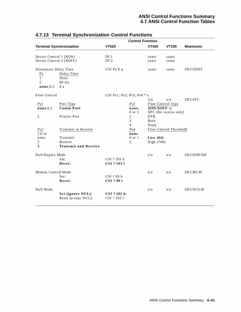
ANSI Control Functions Summary4.7 ANSI Control Function Tables
4.7.13 Terminal Synchronization Control FunctionsControl Function
Terminal Synchronization VT520 VT420 VT100 Mnemonic
Device Control 1 (XON) DC1 same sameDevice Control 3 (XOFF) DC3 same same
Disconnect Delay Time CSI Ps $ q same same DECSDDTPs Delay Time1 None2 60 msnone,0,3 2 s
Flow Control CSI Ps1; Ps2; Ps3; Ps4 * sn/a n/a DECSFC
Ps1 Port Type Ps3 Flow Control Typenone,0,1 Comm Port none,
0 or 1XON/XOFF orXPC (for receive only)
2 Printer Port 2 DTR3 Both4 None
Ps2 Transmit or Receive Ps4 Flow Control Threshold1,0 ornone Transmit
none0 or 1 Low (64)
2 Receive 2 High (768)3 Transmit and Receive
Half-Duplex Mode n/a n/a DECHDPXMSet: CSI ? 103 hReset: CSI ? 103 l
Modem Control Mode n/a n/a DECMCMSet: CSI ? 99 hReset: CSI ? 99 l
Null Mode n/a n/a DECNULMSet (ignore NUL): CSI ? 102 hReset (accept NUL): CSI ? 102 l
ANSI Control Functions Summary 4–41

ANSI Control Functions Summary4.7 ANSI Control Function Tables
4.7.14 Reports Control FunctionsControl Function
Macros VT520 VT420 VT100 Mnemonic
Define Macro DCS Pid;Pdt;Pen ! z D...D STsame n/a DECDMAC
DSR - Macro Space CSI ? 62 n same n/a DSR-MSRInvoke Macro CSI Pid * z same n/a DECINVMMacro Space Report CSI Pn * { same n/a DECMSR,
DSR-MSRPn = number of bytes
16
Reports
Device Status Report – ANSI: CSI Ps n same same DSR– DEC: CSI ? Ps n same same DSR
DSR - Data Integrity Report CSI ? 75 n same n/a DSR-DataResponse: CSI ? Ps n
Ps Meaning70 Ready, no power loss or
comm errors.71 Malfunction, comm error.73 No reported data loss
since last power up.
Memory Checksum Report or DSR-Memory Checksum
CSI ? 63; Pid n same n/a DECCKSR orDSR-Mem
Response: DCS Pid ! ~ D...D ST
Request Checksum of Rect Area CSI Pid;Pp;Pt;Pl;Pb;Pr * ysame n/a DECRQCRA
Response: DCS Pid ! ~ D...D ST
Presentation State Report(See DECRQPSR.)
n/a n/a DECPSR
Report Mode (DECRPM)(See Report Mode (ANSI) below.)
same n/a DECRPM
Request Mode (ANSI) CSI Pa $ p same n/a DECRQM1
Request Mode (DEC) CSI ? Pd $ p same n/a DECRQM
Request Presentation State Report CSI Ps $ w same n/a DECRQPSRPs Report Requested0 Error, restore ignored.1 Cursor information report (DECCIR)2 Tab stop report (DECTABSR)
1A DECRQM sequence can only ask about one mode at a time. When the terminal is set to VT52 mode, DECRQMprovides no report.
4–42 ANSI Control Functions Summary
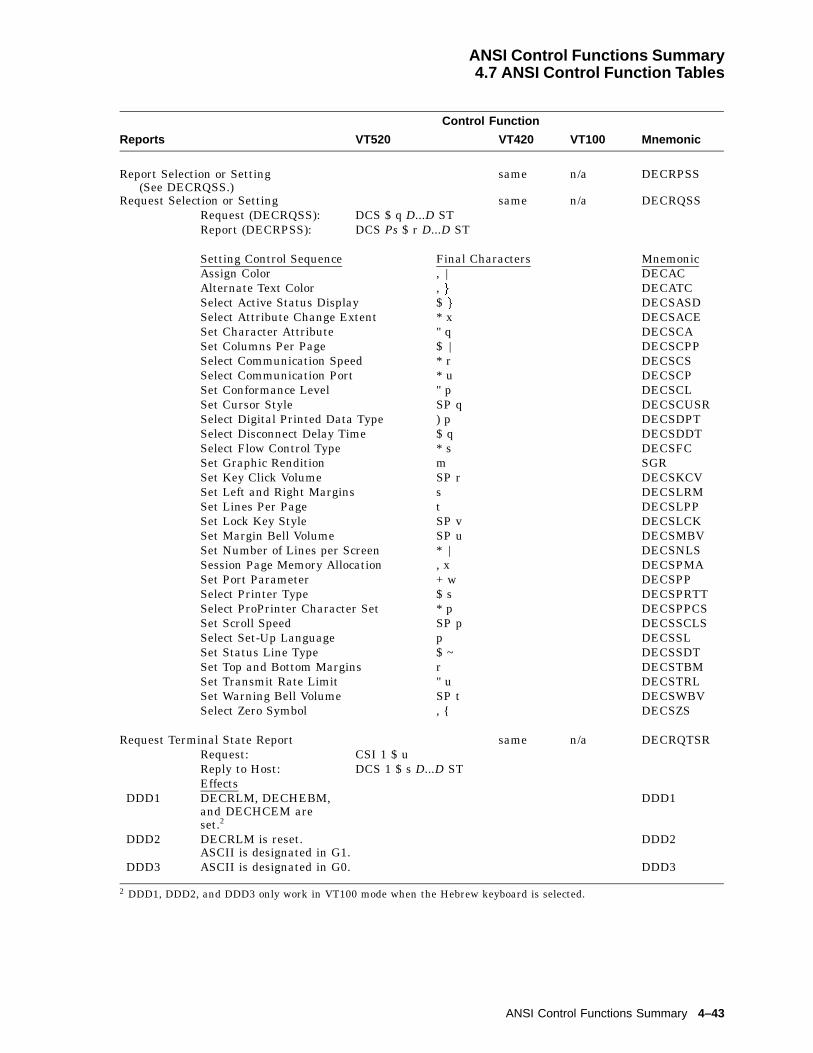
ANSI Control Functions Summary4.7 ANSI Control Function Tables
Control Function
Reports VT520 VT420 VT100 Mnemonic
Report Selection or Setting(See DECRQSS.)
same n/a DECRPSS
Request Selection or Setting same n/a DECRQSSRequest (DECRQSS): DCS $ q D...D STReport (DECRPSS): DCS Ps $ r D...D ST
Setting Control Sequence Final Characters MnemonicAssign Color , | DECACAlternate Text Color , g DECATCSelect Active Status Display $ g DECSASDSelect Attribute Change Extent * x DECSACESet Character Attribute " q DECSCASet Columns Per Page $ | DECSCPPSelect Communication Speed * r DECSCSSelect Communication Port * u DECSCPSet Conformance Level " p DECSCLSet Cursor Style SP q DECSCUSRSelect Digital Printed Data Type ) p DECSDPTSelect Disconnect Delay Time $ q DECSDDTSelect Flow Control Type * s DECSFCSet Graphic Rendition m SGRSet Key Click Volume SP r DECSKCVSet Left and Right Margins s DECSLRMSet Lines Per Page t DECSLPPSet Lock Key Style SP v DECSLCKSet Margin Bell Volume SP u DECSMBVSet Number of Lines per Screen * | DECSNLSSession Page Memory Allocation , x DECSPMASet Port Parameter + w DECSPPSelect Printer Type $ s DECSPRTTSelect ProPrinter Character Set * p DECSPPCSSet Scroll Speed SP p DECSSCLSSelect Set-Up Language p DECSSLSet Status Line Type $ ~ DECSSDTSet Top and Bottom Margins r DECSTBMSet Transmit Rate Limit " u DECSTRLSet Warning Bell Volume SP t DECSWBVSelect Zero Symbol , { DECSZS
Request Terminal State Report same n/a DECRQTSRRequest: CSI 1 $ uReply to Host: DCS 1 $ s D...D STEffects
DDD1 DECRLM, DECHEBM,and DECHCEM areset.2
DDD1
DDD2 DECRLM is reset.ASCII is designated in G1.
DDD2
DDD3 ASCII is designated in G0. DDD3
2 DDD1, DDD2, and DDD3 only work in VT100 mode when the Hebrew keyboard is selected.
ANSI Control Functions Summary 4–43
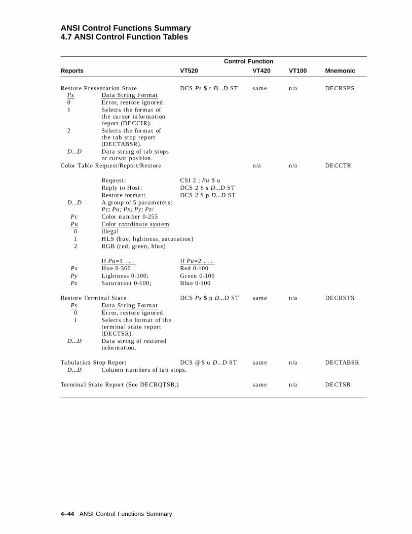
ANSI Control Functions Summary4.7 ANSI Control Function Tables
Control Function
Reports VT520 VT420 VT100 Mnemonic
Restore Presentation State DCS Ps $ t D...D ST same n/a DECRSPSPs Data String Format0 Error, restore ignored.1 Selects the format of
the cursor informationreport (DECCIR).
2 Selects the format ofthe tab stop report(DECTABSR).
D...D Data string of tab stopsor cursor position.
Color Table Request/Report/Restore n/a n/a DECCTR
Request: CSI 2 ; Pu $ uReply to Host: DCS 2 $ s D...D STRestore format: DCS 2 $ p D...D ST
D...D A group of 5 parameters:Pc; Pu; Px; Py; Pz/
Pc Color number 0-255Pu Color coordinate system0 illegal1 HLS (hue, lightness, saturation)2 RGB (red, green, blue)
If Pu=1 . . . If Pu=2 . . .Px Hue 0-360 Red 0-100Py Lightness 0-100; Green 0-100Pz Saturation 0-100; Blue 0-100
Restore Terminal State DCS Ps $ p D...D ST same n/a DECRSTSPs Data String Format0 Error, restore ignored.1 Selects the format of the
terminal state report(DECTSR).
D...D Data string of restoredinformation.
Tabulation Stop Report DCS @ $ u D...D ST same n/a DECTABSRD...D Column numbers of tab stops.
Terminal State Report (See DECRQTSR.) same n/a DECTSR
4–44 ANSI Control Functions Summary

ANSI Control Functions Summary4.8 VT52 Mode Escape Sequences
4.8 VT52 Mode Escape SequencesTable 4–5 shows the escape sequences that the terminal recognizes when theVT52 Emulation Mode is selected.
Table 4–5 VT52 Mode Escape Sequences
Sequence Action
ESC A Cursor up.
ESC B Cursor down.
ESC C Cursor right.
ESC D Cursor left.
ESC F Enter graphics mode.
ESC G Exit graphics mode.
ESC H Move the cursor to the home position.
ESC I Reverse line feed.
ESC J Erase from the cursor to the end of the screen.
ESC K Erase from the cursor to the end of the line.
ESC = Enter alternate keypad mode.
ESC > Exit alternate keypad mode.
ESC < Exit VT52 mode.
ESC ^ Enter autoprint mode.
ESC _ Exit autoprint mode.
ESC V Print the line with the cursor.
ESC W Enter printer controller mode.
ESC X Exit printer controller mode.
ESC ] Print the screen.
ESC Y Pn Move the cursor to column Pn.
ESC Z Identify (host to terminal).
ESC / Z Report (terminal to host).
ANSI Control Functions Summary 4–45

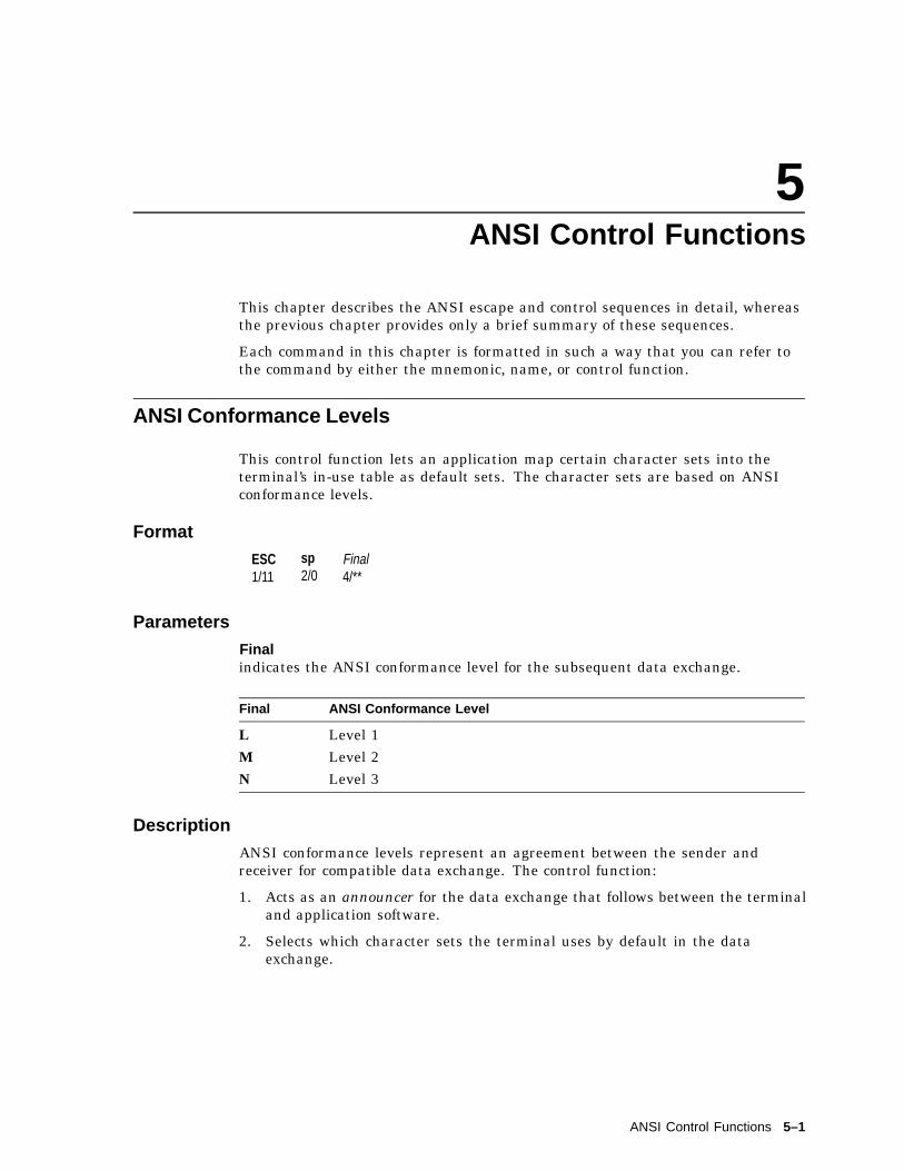
5ANSI Control Functions
This chapter describes the ANSI escape and control sequences in detail, whereasthe previous chapter provides only a brief summary of these sequences.
Each command in this chapter is formatted in such a way that you can refer tothe command by either the mnemonic, name, or control function.
ANSI Conformance Levels
This control function lets an application map certain character sets into theterminal’s in-use table as default sets. The character sets are based on ANSIconformance levels.
Format
ESC1/11
sp2/0
Final4/**
Parameters
Finalindicates the ANSI conformance level for the subsequent data exchange.
Final ANSI Conformance Level
L Level 1M Level 2N Level 3
Description
ANSI conformance levels represent an agreement between the sender andreceiver for compatible data exchange. The control function:
1. Acts as an announcer for the data exchange that follows between the terminaland application software.
2. Selects which character sets the terminal uses by default in the dataexchange.
ANSI Control Functions 5–1
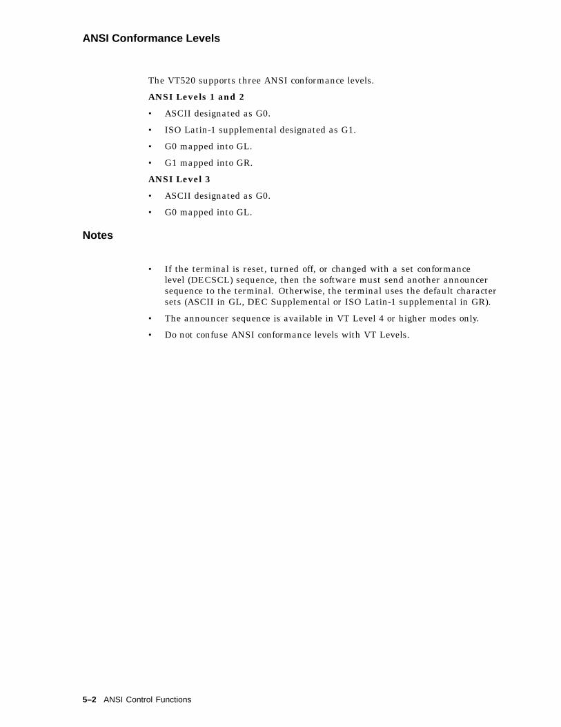
ANSI Conformance Levels
The VT520 supports three ANSI conformance levels.
ANSI Levels 1 and 2
• ASCII designated as G0.
• ISO Latin-1 supplemental designated as G1.
• G0 mapped into GL.
• G1 mapped into GR.
ANSI Level 3
• ASCII designated as G0.
• G0 mapped into GL.
Notes
• If the terminal is reset, turned off, or changed with a set conformancelevel (DECSCL) sequence, then the software must send another announcersequence to the terminal. Otherwise, the terminal uses the default charactersets (ASCII in GL, DEC Supplemental or ISO Latin-1 supplemental in GR).
• The announcer sequence is available in VT Level 4 or higher modes only.
• Do not confuse ANSI conformance levels with VT Levels.
5–2 ANSI Control Functions

CBT—Cursor Backward Tabulation
CBT—Cursor Backward Tabulation
Move the active position n tabs backward.
Default: 1.
Format
CSI9/11
Pn3/n
Z5/10
Parameters
Pnis the number of active position tabs to move backward.
Description
The active position is moved to the character position corresponding to the n-thpreceding horizontal tabulation stop. If an attempt is made to move the activeposition past the first character position on the line, then the active position staysat column one.
CHA—Cursor Horizontal Absolute
Move the active position to the n-th character of the active line.
Default: 1.
Format
CSI9/11
Pn3/n
G4/7
Parameters
Pnis the number of active positions to the n-th character of the active line.
Description
The active position is moved to the n-th character position of the active line.
ANSI Control Functions 5–3

CHT—Cursor Horizontal Forward Tabulation
CHT—Cursor Horizontal Forward Tabulation
Move the active position n tabs forward.
Default: 1.
Format
CSI9/11
Pn3/n
I4/9
Parameters
Pnis the number of active position tabs to move forward.
Description
The active position is moved to the character position corresponding to thefollowing n-th horizontal tabulation stop.
CNL—Cursor Next Line
Move the cursor to the next line.
Default: 1.
Format
CSI9/11
Pn3/n
E4/5
Parameters
Pnis the active position to the first character of the n-th following line.
Description
The active position is moved to the first character of the n-th following line.
5–4 ANSI Control Functions

CPL—Cursor Previous Line
CPL—Cursor Previous Line
Move the cursor to the preceding line.
Default: 1.
Format
CSI9/11
Pn3/n
F4/6
Parameters
Pnis the number of active position moved to the first character of the n-th precedingline.
Description
The active position is moved to the first character of the n-th preceding line.
CPR—Cursor Position Report
The host asks the terminal for a cursor position report.
Format
CSI9/11
63/6
n6/14 Request cursor position.
CSI9/11
Pl3/n
;3/11
Pc3/n
R5/2
Report cursor position.
Parameters
Plindicates what line the cursor is on.
Pcindicates what column the cursor is at.
ANSI Control Functions 5–5
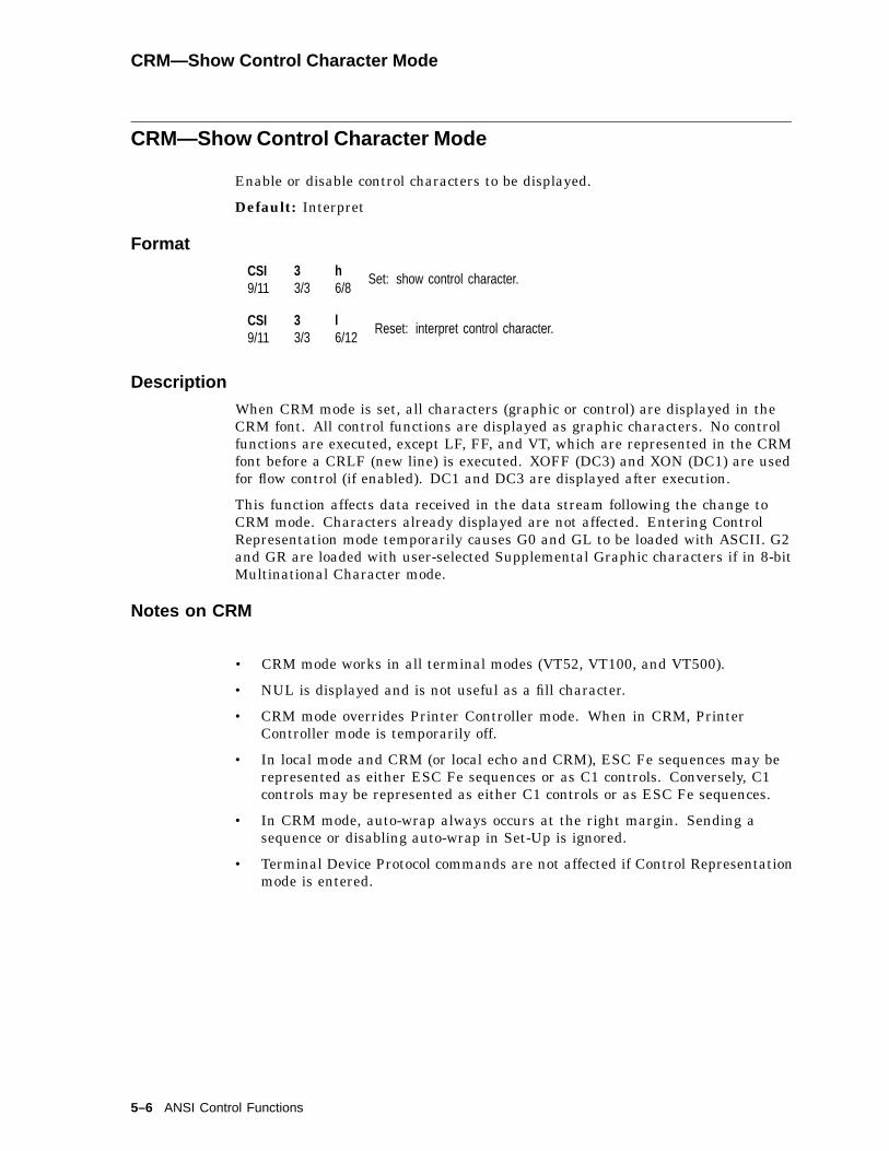
CRM—Show Control Character Mode
CRM—Show Control Character Mode
Enable or disable control characters to be displayed.
Default: Interpret
Format
CSI9/11
33/3
h6/8
Set: show control character.
CSI9/11
33/3
l6/12
Reset: interpret control character.
Description
When CRM mode is set, all characters (graphic or control) are displayed in theCRM font. All control functions are displayed as graphic characters. No controlfunctions are executed, except LF, FF, and VT, which are represented in the CRMfont before a CRLF (new line) is executed. XOFF (DC3) and XON (DC1) are usedfor flow control (if enabled). DC1 and DC3 are displayed after execution.
This function affects data received in the data stream following the change toCRM mode. Characters already displayed are not affected. Entering ControlRepresentation mode temporarily causes G0 and GL to be loaded with ASCII. G2and GR are loaded with user-selected Supplemental Graphic characters if in 8-bitMultinational Character mode.
Notes on CRM
• CRM mode works in all terminal modes (VT52, VT100, and VT500).
• NUL is displayed and is not useful as a fill character.
• CRM mode overrides Printer Controller mode. When in CRM, PrinterController mode is temporarily off.
• In local mode and CRM (or local echo and CRM), ESC Fe sequences may berepresented as either ESC Fe sequences or as C1 controls. Conversely, C1controls may be represented as either C1 controls or as ESC Fe sequences.
• In CRM mode, auto-wrap always occurs at the right margin. Sending asequence or disabling auto-wrap in Set-Up is ignored.
• Terminal Device Protocol commands are not affected if Control Representationmode is entered.
5–6 ANSI Control Functions

CUB—Cursor Backward
CUB—Cursor Backward
This control function moves the cursor to the left by a specified number ofcolumns. The cursor stops at the left border of the page.
Format
CSI9/11
Pn3/n
D4/4
Parameters
Pnis the number of columns to move the cursor to the left.
CUD—Cursor Down
This control function moves the cursor down a specified number of lines in thesame column. The cursor stops at the bottom margin. If the cursor is alreadybelow the bottom margin, then the cursor stops at the bottom line.
Format
CSI9/11
Pn3/n
B4/2
Parameters
Pnis the number of lines to move the cursor down.
CUF—Cursor Forward
This control function moves the cursor to the right by a specified number ofcolumns. The cursor stops at the right border of the page.
Format
CSI9/11
Pn3/n
C4/3
Parameters
Pnis the number of columns to move the cursor to the right.
ANSI Control Functions 5–7
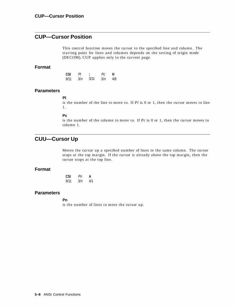
CUP—Cursor Position
CUP—Cursor Position
This control function moves the cursor to the specified line and column. Thestarting point for lines and columns depends on the setting of origin mode(DECOM). CUP applies only to the current page.
Format
CSI9/11
Pl3/n
;3/11
Pc3/n
H4/8
Parameters
Plis the number of the line to move to. If Pl is 0 or 1, then the cursor moves to line1.
Pcis the number of the column to move to. If Pc is 0 or 1, then the cursor moves tocolumn 1.
CUU—Cursor Up
Moves the cursor up a specified number of lines in the same column. The cursorstops at the top margin. If the cursor is already above the top margin, then thecursor stops at the top line.
Format
CSI9/11
Pn3/n
A4/1
Parameters
Pnis the number of lines to move the cursor up.
5–8 ANSI Control Functions
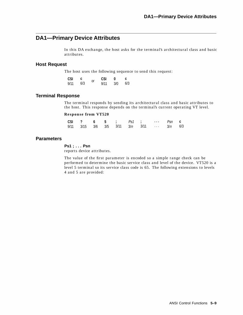
DA1—Primary Device Attributes
DA1—Primary Device Attributes
In this DA exchange, the host asks for the terminal’s architectural class and basicattributes.
Host RequestThe host uses the following sequence to send this request:
CSI9/11
c6/3
or CSI9/11
03/0
c6/3
Terminal ResponseThe terminal responds by sending its architectural class and basic attributes tothe host. This response depends on the terminal’s current operating VT level.
Response from VT520
CSI9/11
?3/15
63/6
53/5
;3/11
Ps13/n
;3/11
. . .
. . .Psn3/n
c6/3
Parameters
Ps1 ; . . . Psnreports device attributes.
The value of the first parameter is encoded so a simple range check can beperformed to determine the basic service class and level of the device. VT520 is alevel 5 terminal so its service class code is 65. The following extensions to levels4 and 5 are provided:
ANSI Control Functions 5–9

DA1—Primary Device Attributes
Ps Meaning
1 132 columns2 Printer port6 Selective erase7 Soft character set (DRCS)8 User-defined keys (UDKs)9 National replacement character sets (NRCS)
12 Serbo-Croatian (SCS)15 Technical character set18 Windowing capability19 Sessions21 Horizontal scrolling22 Color23 Greek24 Turkish42 ISO Latin-244 PCTerm45 Soft key mapping46 ASCII terminal emulation
Primary DA Example
Here is a typical primary DA exchange.
Exchange Sequence Meaning
Request(Host to VT520)
CSI c or CSI 0 c The host asks for the terminal’sarchitectural class code and supportedextensions.
Response(VT520 to host)
CSI ? 65; 1; 2;7; 9; 12; 18; 19; 21; 23;24; 42; 44; 45; 46 c
The terminal is a level 5 device (65) andsupports the Ps parameters listed above.The DA1 response above is used when the"Terminal ID to host" is set to VT520 andthe conformance level is set to Level 5(factory default). Extensions: 6 (selectiveerase); 8 (UDK); and 15 (technical characterset) are not reported explicitly at Level 5.
5–10 ANSI Control Functions
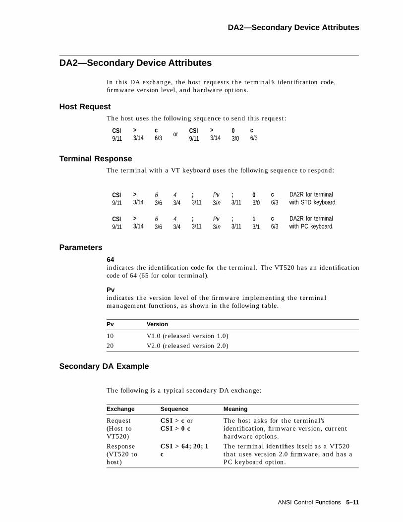
DA2—Secondary Device Attributes
DA2—Secondary Device Attributes
In this DA exchange, the host requests the terminal’s identification code,firmware version level, and hardware options.
Host RequestThe host uses the following sequence to send this request:
CSI9/11
>3/14
c6/3
or CSI9/11
>3/14
03/0
c6/3
Terminal ResponseThe terminal with a VT keyboard uses the following sequence to respond:
CSI9/11
>3/14
63/6
43/4
;3/11
Pv3/n
;3/11
03/0
c6/3
DA2R for terminalwith STD keyboard.
CSI9/11
>3/14
63/6
43/4
;3/11
Pv3/n
;3/11
13/1
c6/3
DA2R for terminalwith PC keyboard.
Parameters
64indicates the identification code for the terminal. The VT520 has an identificationcode of 64 (65 for color terminal).
Pvindicates the version level of the firmware implementing the terminalmanagement functions, as shown in the following table.
Pv Version
10 V1.0 (released version 1.0)20 V2.0 (released version 2.0)
Secondary DA Example
The following is a typical secondary DA exchange:
Exchange Sequence Meaning
Request(Host toVT520)
CSI > c orCSI > 0 c
The host asks for the terminal’sidentification, firmware version, currenthardware options.
Response(VT520 tohost)
CSI > 64; 20; 1c
The terminal identifies itself as a VT520that uses version 2.0 firmware, and has aPC keyboard option.
ANSI Control Functions 5–11
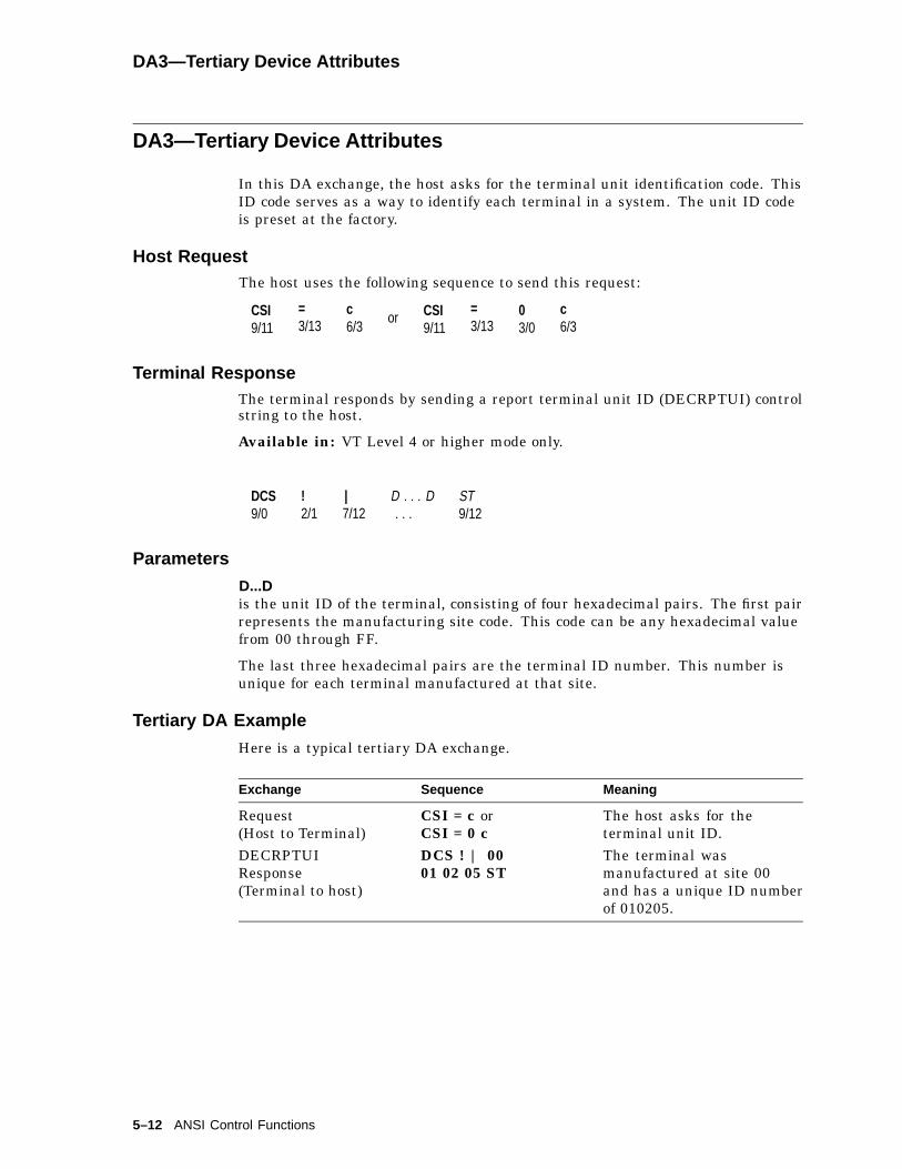
DA3—Tertiary Device Attributes
DA3—Tertiary Device Attributes
In this DA exchange, the host asks for the terminal unit identification code. ThisID code serves as a way to identify each terminal in a system. The unit ID codeis preset at the factory.
Host RequestThe host uses the following sequence to send this request:
CSI9/11
=3/13
c6/3
or CSI9/11
=3/13
03/0
c6/3
Terminal ResponseThe terminal responds by sending a report terminal unit ID (DECRPTUI) controlstring to the host.
Available in: VT Level 4 or higher mode only.
DCS9/0
!2/1
|7/12
D . . . D. . .
ST9/12
Parameters
D...Dis the unit ID of the terminal, consisting of four hexadecimal pairs. The first pairrepresents the manufacturing site code. This code can be any hexadecimal valuefrom 00 through FF.
The last three hexadecimal pairs are the terminal ID number. This number isunique for each terminal manufactured at that site.
Tertiary DA Example
Here is a typical tertiary DA exchange.
Exchange Sequence Meaning
Request(Host to Terminal)
CSI = c orCSI = 0 c
The host asks for theterminal unit ID.
DECRPTUIResponse(Terminal to host)
DCS ! | 0001 02 05 ST
The terminal wasmanufactured at site 00and has a unique ID numberof 010205.
5–12 ANSI Control Functions
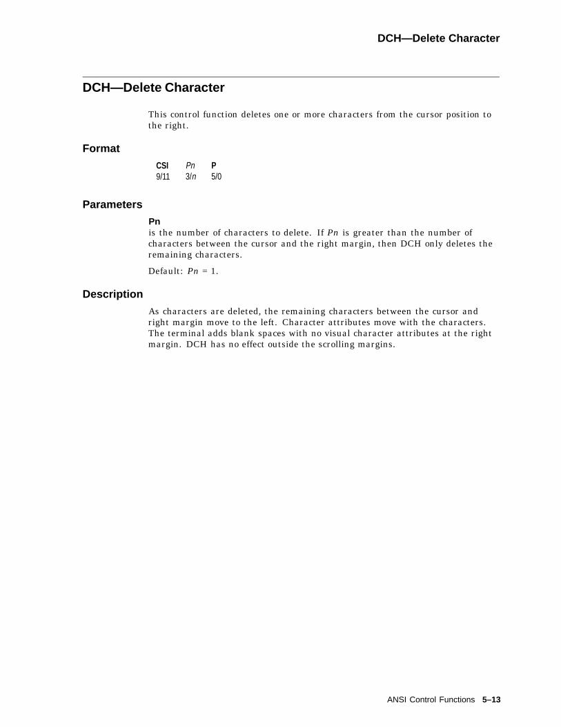
DCH—Delete Character
DCH—Delete Character
This control function deletes one or more characters from the cursor position tothe right.
Format
CSI9/11
Pn3/n
P5/0
Parameters
Pnis the number of characters to delete. If Pn is greater than the number ofcharacters between the cursor and the right margin, then DCH only deletes theremaining characters.
Default: Pn = 1.
Description
As characters are deleted, the remaining characters between the cursor andright margin move to the left. Character attributes move with the characters.The terminal adds blank spaces with no visual character attributes at the rightmargin. DCH has no effect outside the scrolling margins.
ANSI Control Functions 5–13

DDD1, DDD2, DDD3
DDD1, DDD2, DDD3
DDD2 and DDD3 only work in VT100 mode when the Hebrew keyboard, DDD1,is selected.
Format
ESC1/7
)2/9
13/1
DDD1
ESC1/7
)2/9
B4/2
DDD2
ESC1/7
(2/8
13/1
DDD3
Description
These escape sequences have the follow effects:
Escape Sequence Effect
DDD1 DECRLM is set.DECHEBM is set.DECHEM is set
DDD2 DECRLM is reset.ASCII is designated in G1.
DDD3 ASCII is designated in G0.
5–14 ANSI Control Functions
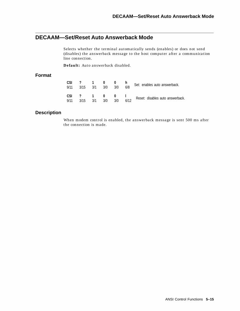
DECAAM—Set/Reset Auto Answerback Mode
DECAAM—Set/Reset Auto Answerback Mode
Selects whether the terminal automatically sends (enables) or does not send(disables) the answerback message to the host computer after a communicationline connection.
Default: Auto answerback disabled.
Format
CSI9/11
?3/15
13/1
03/0
03/0
h6/8
Set: enables auto answerback.
CSI9/11
?3/15
13/1
03/0
03/0
l6/12
Reset: disables auto answerback.
Description
When modem control is enabled, the answerback message is sent 500 ms afterthe connection is made.
ANSI Control Functions 5–15

DECAC—Assign Color
DECAC—Assign Color
Selects the colors used for normal text.
Default: ANSI SGR color
Format
CSI9/11
Ps1 Ps2 Ps3,2/12
|7/12
Parameters
Ps1Item
Ps1 Color Item
1 Normal text2 Window frame
Ps2Foreground color index
0...15
Ps3Background color index
0...15
Description
DECAC selects the foreground and background colors used for normal text inANSI SGR color mode and the window frame colors. The normal text colorsare used in ANSI SGR color mode as the default foreground and backgroundcolors. The window frame foreground color is also used for the session icons andkeyboard indicator line.
DECAC can be reported using DECRQSS and DECRPSS. Use Ps1 in DECRQSSto select the item to be reported.
5–16 ANSI Control Functions

DECALN—Screen Alignment Pattern
DECALN—Screen Alignment Pattern
This control function fills the complete screen area with a test pattern used foradjusting screen alignment. Normally, only manufacturing and service personnelwould use DECALN.
Format
ESC1/11
#2/3
83/8
Notes on DECALN
DECALN sets the margins to the extremes of the page, and moves the cursor tothe home position.
Also see the screen alignment in Chapter 2.
ANSI Control Functions 5–17
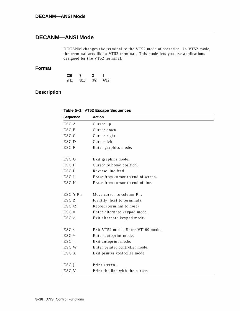
DECANM—ANSI Mode
DECANM—ANSI Mode
DECANM changes the terminal to the VT52 mode of operation. In VT52 mode,the terminal acts like a VT52 terminal. This mode lets you use applicationsdesigned for the VT52 terminal.
Format
CSI9/11
?3/15
23/2
l6/12
Description
Table 5–1 VT52 Escape Sequences
Sequence Action
ESC A Cursor up.ESC B Cursor down.ESC C Cursor right.ESC D Cursor left.ESC F Enter graphics mode.
ESC G Exit graphics mode.ESC H Cursor to home position.ESC I Reverse line feed.ESC J Erase from cursor to end of screen.ESC K Erase from cursor to end of line.
ESC Y Pn Move cursor to column Pn.ESC Z Identify (host to terminal).ESC /Z Report (terminal to host).ESC = Enter alternate keypad mode.ESC > Exit alternate keypad mode.
ESC < Exit VT52 mode. Enter VT100 mode.ESC ^ Enter autoprint mode.ESC _ Exit autoprint mode.ESC W Enter printer controller mode.ESC X Exit printer controller mode.
ESC ] Print screen.ESC V Print the line with the cursor.
5–18 ANSI Control Functions

DECANM Exit—Exiting ANSI (VT52) Mode
DECANM Exit—Exiting ANSI (VT52) Mode
When the terminal exits VT52 mode, it returns to the previous mode beforeentering VT52 mode. The terminal exits VT52 mode with the following escapesequence:
Format
ESC1/11
<3/12
DECARM—Autorepeat Mode
This control function determines whether or not keys automatically repeat theircharacter when held down. If DECARM is set, then most keys you press for morethan 0.5 seconds send a character repeatedly until you release the key.
Default: Repeat (set)
Format
CSI9/11
?3/15
83/8
h6/8
Set: keys autorepeat when pressedfor more than 0.5 seconds.
CSI9/11
?3/15
83/8
l6/12
Reset: keys do not autorepeat.
Notes on DECARM
• The following keys on the VT keyboard do not repeat:
F1 (Hold)F2 (Print)F3 (Set-Up)F4 (Session)
F5 (Break)Compose Character
Shift
Alt Function
Return
Lock
Ctrl
Extend
• The following keys on the PC keyboard do not repeat:
Alt AltGr
Caps Lock Pause
Ctrl Print Screen
Enter Scroll Lock
Num Lock Shift
ANSI Control Functions 5–19

DECARR—Select Auto Repeat Rate
DECARR—Select Auto Repeat Rate
Controls the keystroke auto repeat rate.
Default: Fast (30/sec)
Format
CSI9/11
Ps-2/13
p7/0
Parameters
PsAuto Repeat Rate
Ps Selection
0...5 Off6...15 Slow (10 cps)16...30 Fast (30 cps)
Description
DECARR controls the keystroke auto-repeat rate. Values for Ps outside thedefined range are ignored.
DECARR can be reported using DECRPSS.
5–20 ANSI Control Functions

DECARSM—Set/Reset Auto Resize Mode
DECARSM—Set/Reset Auto Resize Mode
Enable or disable changing the lines per screen automatically when the pagearrangement changes.
Default: Auto resize disabled
Format
CSI9/11
?3/15
93/9
83/8
h6/8
Set: enable auto resize.
CSI9/11
?3/15
93/9
83/8
l6/12
Reset: disable auto resize.
Description
When Auto Resize is enabled, the number of Lines/Screen changes automaticallyeach time the page arrangement changes.
Auto Resize and Number of lines per screen are user features that can belocked from being redefined by the host if the User Feature Lock in Set-Up isenabled.
The following table indicates how the lines/screen changes when the page sizechanges, assuming Auto Resize is set.
Page size Lines/Screen
24 26 (24 data lines, 1 status line, 1 blank line)25 26 (25 data lines, 1 status line)36 42 (36 data lines, 1 status line, 5 blank lines)41 42 (41 data lines, 1 status line)42 42 (42 data lines, no status line)48 53 (48 data lines, 1 status line, 4 blank lines)52 53 (52 data lines, 1 status line)53 53 (53 data lines, 0 status line)72 53 (53 data lines, 0 status line)
ANSI Control Functions 5–21

DECATC—Alternate Text Color
DECATC—Alternate Text Color
Selects the colors used for text attribute combinations.
Format
CSI9/11
Ps1 Ps2 Ps3,2/12
}7/13
Parameters
Ps1Attribute combinations
Ps1 Attributes
0 Normal text1 Bold2 Reverse3 Underline4 Blink5 Bold reverse6 Bold underline7 Bold blink8 Reverse underline9 Reverse blink
10 Underline blink11 Bold reverse underline12 Bold reverse blink13 Bold underline blink14 Reverse underline blink15 Bold reverse underline blink
Ps2Foreground color index
0...15
Ps3Background color index
0...15
Description
DECATC can be reported using DECRQSS and DECRPSS. Use Ps1 in DECRQSSto select the attribute combination to be reported.
5–22 ANSI Control Functions

DECATCBM—Set/Reset Alternate Text Color Blink Mode
DECATCBM—Set/Reset Alternate Text Color Blink Mode
Allows text with blink attributes to blink.
Format
CSI9/11
?3/15
13/1
13/1
53/5
h6/8
Set: enables blink text mode
CSI9/11
?3/15
13/1
13/1
53/5
l6/12
Reset: disables blink text mode
Description
If blink text is selected, text with the blink attribute will blink, as well asdisplayed using the specified alternate text colors. See Alternate Text Colors inSet-Up for details.
DECATCBM can be reported using DECRQM and DECRPM.
DECATCUM—Set/Reset Alternate Text Color Underline Mode
Allows text with underline attributes to be displayed in alternate color.
Format
CSI9/11
?3/15
13/1
13/1
43/4
h6/8
Set: enables underline text mode
CSI9/11
?3/15
13/1
13/1
43/4
l6/12
Reset: disables underline text mode
Description
If underline text is selected, text with the underline attribute will beunderlined, as well as displayed using the specified alternate text colors. SeeAlternate Text Colors in Set-Up for details.
DECATCUM can be reported using DECRQM and DECRPM.
ANSI Control Functions 5–23

DECAUPSS—Assigning User-Preferred Supplemental Sets
DECAUPSS—Assigning User-Preferred Supplemental Sets
You can assign the supplemental character set you use most often as a specialstandby set. This standby set is called the user-preferred supplemental set. Thisfeature provides applications with an easy way to access the user’s preferredsupplemental set.
Default: DEC Supplemental Graphic
Format
DCS9/0
Pn3/n
!2/1
u7/5
Dscs3/n
ST9/12
Parameters
Pnrepresents a character set designator.
Pn Meaning
0 DEC, ISO Latin-1, ISO Latin-21 ISO Latin-5, ISO Latin-7, ISO Cyrillic, ISO Hebrew
Dscsrepresents a character set.
Dscs Character Set
% 5 DEC Supplemental" ? DEC Greek" 4 DEC Hebrew% 0 DEC Turkish& 4 DEC Cyrillic< User-preferred SupplementalA ISO Latin-1 SupplementalB ISO Latin-2 SupplementalF ISO Greek SupplementalH ISO Hebrew SupplementalM ISO Latin-5 SupplementalL ISO Latin-Cyrillic
Description
You can assign any supplemental or ISO Latin supplemental set as the standbyset. See SCS—Select Character Set for more information.
After you assign a set:
1. Designate the set as G1, G2, or G3.
2. Map the set into GR.
5–24 ANSI Control Functions

DECAWM—Autowrap Mode
DECAWM—Autowrap Mode
This control function determines whether or not received characters automaticallywrap to the next line when the cursor reaches the right border of a page in pagememory.
Default: No autowrap
Format
CSI9/11
?3/15
73/7
h6/8
Set: autowrap.
CSI9/11
?3/15
73/7
l6/12
Reset: no autowrap.
Description
If the DECAWM function is set, then graphic characters received when the cursoris at the right border of the page appear at the beginning of the next line. Anytext on the page scrolls up if the cursor is at the end of the scrolling region.
If the DECAWM function is reset, then graphic characters received when thecursor is at the right border of the page replace any previous characters there.
DECBBSM—Bold and Blink Style Mode
Selects whether the bold and blink attributes affect the text foreground only orboth the foreground and background.
Format
CSI9/11
?3/15
13/1
13/1
63/6
h6/8
Set: foreground and background
CSI9/11
?3/15
13/1
13/1
63/6
l6/12
Reset: foreground only - default
Description
This setting selects whether the bold and blink attributes affect the textforeground only, or both foreground and background. See the Set-Up chapterfor details.
DECBBSM can be reported using DECRQM and DECRPM.
ANSI Control Functions 5–25

DECBI—Back Index
DECBI—Back Index
This control function moves the cursor backward one column. If the cursor is atthe left margin, then all screen data within the margin moves one column to theright. The column that shifted past the right margin is lost.
Available in: VT Level 4 or higher mode only
Format
ESC1/11
63/6
Description
DECBI adds a new column at the left margin with no visual attributes. DECBIis not affected by the margins. If the cursor is at the left border of the page whenthe terminal receives DECBI, then the terminal ignores DECBI.
DECBKM—Backarrow Key Mode
This control function determines whether the <x key works as a backspace keyor delete key.
Note
To be compatible with some software, DECBKM should be reset (deletekey setting).
Default: Delete key
Format
CSI9/11
?3/15
63/6
73/7
h6/8
Set: backspace key.
CSI9/11
?3/15
63/6
73/7
l6/12
Reset: delete key.
Description
If DECBKM is set, <x works as a backspace key. When you press <x , theterminal sends a BS character to the host.
If DECBKM is reset, <x works as a delete key. When you press <x , the terminalsends a DEL character to the host.
5–26 ANSI Control Functions
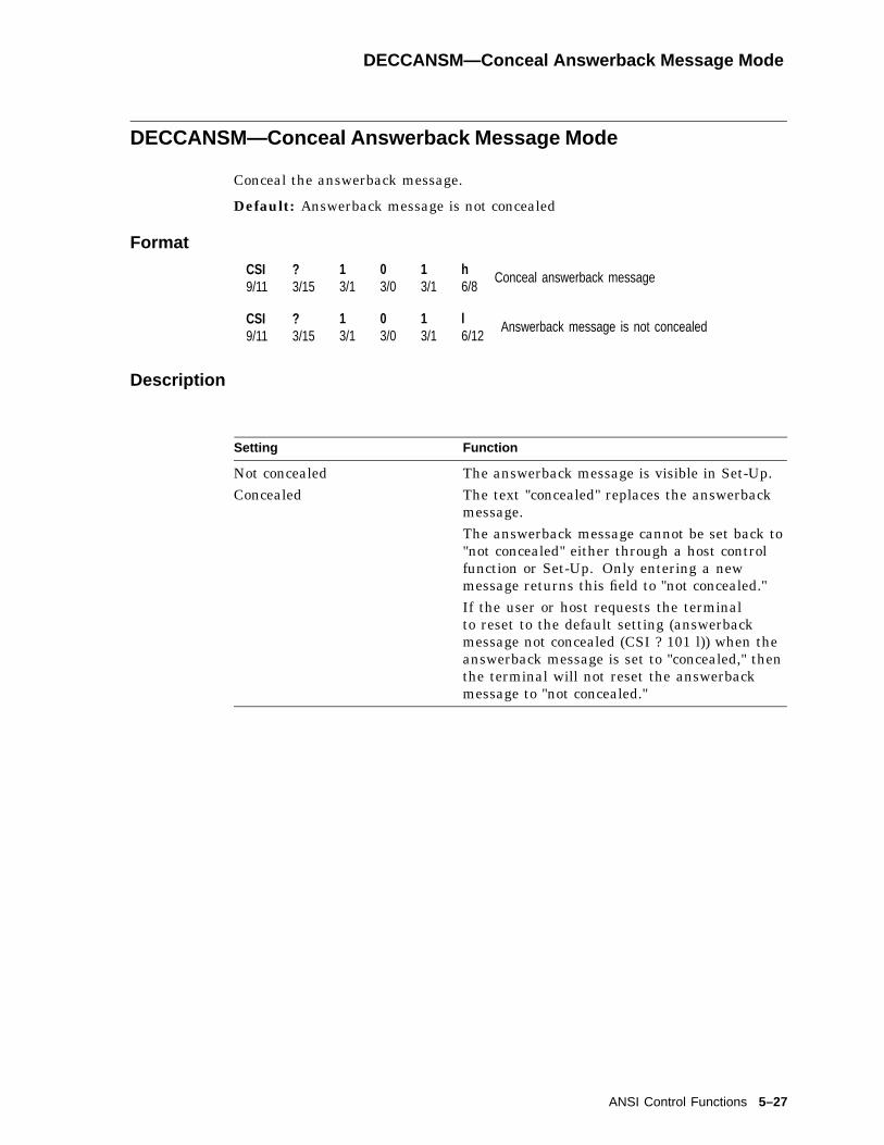
DECCANSM—Conceal Answerback Message Mode
DECCANSM—Conceal Answerback Message Mode
Conceal the answerback message.
Default: Answerback message is not concealed
Format
CSI9/11
?3/15
13/1
03/0
13/1
h6/8
Conceal answerback message
CSI9/11
?3/15
13/1
03/0
13/1
l6/12
Answerback message is not concealed
Description
Setting Function
Not concealed The answerback message is visible in Set-Up.Concealed The text "concealed" replaces the answerback
message.The answerback message cannot be set back to"not concealed" either through a host controlfunction or Set-Up. Only entering a newmessage returns this field to "not concealed."If the user or host requests the terminalto reset to the default setting (answerbackmessage not concealed (CSI ? 101 l)) when theanswerback message is set to "concealed," thenthe terminal will not reset the answerbackmessage to "not concealed."
ANSI Control Functions 5–27

DECCAPSLK—Caps Lock Mode
DECCAPSLK—Caps Lock Mode
DECCAPSLK controls the CapsLock state of the keyboard as if the CapsLock keyhad been pressed.
Format
CSI9/11
?3/15
13/1
03/0
93/9
h6/8
Set: Lock on.
CSI9/11
?3/15
13/1
03/0
93/9
l6/12
Reset: Lock off.
DECCARA—Change Attributes in Rectangular Area
This control function lets you change the visual character attributes (bold, blink,reverse video, and underline) of a specified rectangular area in page memory. Theselect attribute change extent (DECSACE) control function determines the streamor rectangular area. DECCARA does not change the values of characters just thevisual attributes of those characters.
Available in: VT Level 4 or higher mode only
Format
CSI9/11
Pt; Pl; Pb; Pr;area to be changed
Ps1; . . . Psnattributes to change
$2/4
r7/2
Parameters
Pt; Pl; Pb; Pr;define the rectangular area to be changed. A semicolon (3/11) separatesparameters.
Ptis the top-line border. Pt must be less than or equal to Pb.Default: Pt = 1.
P1is the left-column border. Pl must be less than or equal to Pr. Default: Pl = 1.
Pbis the bottom-line border.Default: Pb = last line of the active page.
Pris the right-column border.Default: Pr = last column of the active page.
Ps1; . . . Psnselect the visual character attributes to change. These values correspond to thevalues used in the select graphic rendition.
5–28 ANSI Control Functions

DECCARA—Change Attributes in Rectangular Area
Psn Meaning
0(default)
Attributes off (no bold, no underline, no blink, positive image)
1 Bold4 Underline5 Blink7 Negative image
22 No bold24 No underline25 No blink27 Positive image
DECCARA ignores all other parameter values. When you use more than oneparameter in a command, DECCARA executes them cumulatively in sequence.
Examples
The following sequence changes the video attributes of the complete screen toblink and underscore:
CSI ; ; ; ; 0; 4; 5; $ r
The following sequence turns off the blinking character attribute from positionline 10, column 2 to position line 14, column 45 on the current page:
CSI 10; 2; 14; 45; 25 $ r
Notes on DECCARA
• The coordinates of the rectangular area are affected by the setting of originmode (DECOM).
• DECCARA is not affected by the page margins.
• If the value of Pt, Pl, Pb, or Pr exceeds the width or height of the active page,then the value is treated as the width or height of that page.
• DECCARA does not change the active cursor position.
• DECCARA does not change the current rendition set by the select graphicrendition (SGR) function.
• The exact character positions affected by DECCARA depend on the currentsetting of the select attribute change extent (DECSACE) function.
ANSI Control Functions 5–29
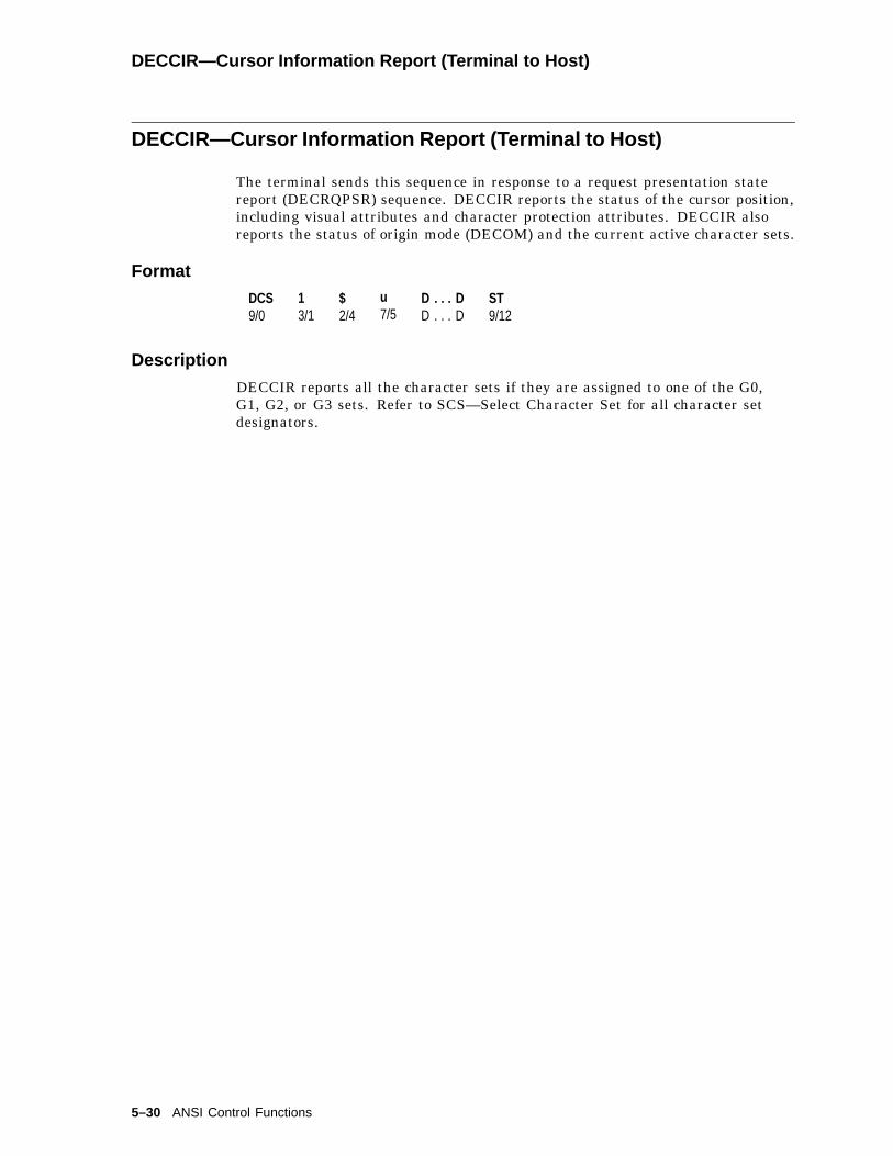
DECCIR—Cursor Information Report (Terminal to Host)
DECCIR—Cursor Information Report (Terminal to Host)
The terminal sends this sequence in response to a request presentation statereport (DECRQPSR) sequence. DECCIR reports the status of the cursor position,including visual attributes and character protection attributes. DECCIR alsoreports the status of origin mode (DECOM) and the current active character sets.
Format
DCS9/0
13/1
$2/4
u7/5
D . . . DD . . . D
ST9/12
Description
DECCIR reports all the character sets if they are assigned to one of the G0,G1, G2, or G3 sets. Refer to SCS—Select Character Set for all character setdesignators.
5–30 ANSI Control Functions

DECCKD—Copy Key Default
DECCKD—Copy Key Default
Copies the default states of a key and its key/modifier combination to another keyand its key/modifier combination.
Format
DCS9/0
"2/2
z7/10
D . . . DD . . . D
ST9/12
Description
This control function copies the default states of a key and all its modifiercombinations to another key and its modifier combinations. The source key mayhave been reprogrammed to perform a non-default function when copy operationis executed. Only the default states of the source key are copied.
The source key and the destination key can be two different keys or the same key.If they are different keys, then the copy operation occupies the memory spacethat is reserved for the operations of control functions, DECPFK, DECPAK, andDECUDK and their equivalent functions in Set-Up. (Refer to DECPFK—ProgramFunction Key for details.) If they are the same key, then the function of thecopy operation is to restore the key’s default. In this state, the terminal doesnot allocate new memory space. The terminal frees up the space by deleting thenon-default functions of the destination key and its modifier combinations.
A function key can copy the default state from a function key or a graphic key.When a graphic key’s default is copied, the function key operates as a graphickey. Only the modifiers that are suitable for a graphic key operate with the key.This logic is used when a graphic key copies the default from a function key.
Multiple keys can be copied in one sequence.
The data string D...D format is:
Key-s/Key-d;Key-s/Key-d........;
Where:
� Key-s is the keystation number of the key to be copied.� Key-d is the keystation number of the destination key.
Once programmed, the key states are not affected by the terminal mode changes.Refer to DECPFK—Program Function Key for the list of terminal mode changes.
This function works in all the VT modes except in VT52 mode.
ANSI Control Functions 5–31
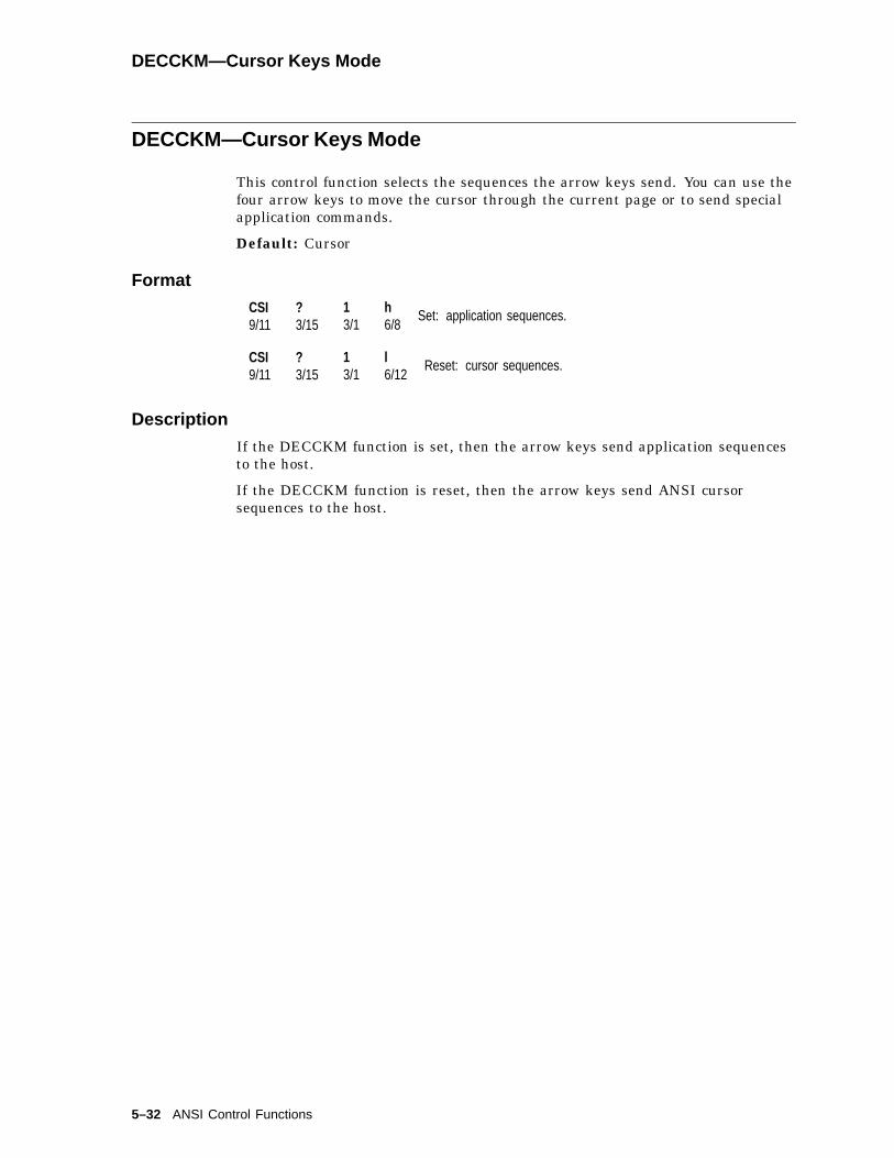
DECCKM—Cursor Keys Mode
DECCKM—Cursor Keys Mode
This control function selects the sequences the arrow keys send. You can use thefour arrow keys to move the cursor through the current page or to send specialapplication commands.
Default: Cursor
Format
CSI9/11
?3/15
13/1
h6/8
Set: application sequences.
CSI9/11
?3/15
13/1
l6/12
Reset: cursor sequences.
Description
If the DECCKM function is set, then the arrow keys send application sequencesto the host.
If the DECCKM function is reset, then the arrow keys send ANSI cursorsequences to the host.
5–32 ANSI Control Functions

DECCKSR—Memory Checksum Report
DECCKSR—Memory Checksum Report
The host asks for a memory checksum report of current text macro definitions.
Programming TipEnter your macro definitions, then request and save a memory checksum. Afterthis procedure, you can request another checksum to determine if the checksumhas changed.
Format
CSI9/11
?3/15
63/6
33/3
;3/11
Pid3/n
n6/14 Request memory checksum.
DCS9/0
Pid3/n
!2/1
~7/14
D . . . D. . .
ST9/12
Response with checksum.
Parameters
Pid (request)is an optional numeric parameter that provides a label to identify the particularchecksum request. The checksum report returns the label. This label lets youdistinguish between multiple checksum reports.
Pid (response)is a label indicating which DSR request the report is for.
D . . . Dis the data string consisting of four hexadecimal digits indicating the checksum.The digits can be in the range of 3/0 through 3/9 and 4/0 through 4/6.
ANSI Control Functions 5–33

DECCOLM—Selecting 80 or 132 Columns per Page
DECCOLM—Selecting 80 or 132 Columns per Page
There are two control functions that can set the page width to 80 or 132 columns,DECSCPP (DECSCPP—Select Columns Per Page ) and DECCOLM.
NOTE
It is recommended that new applications use DECSCPP rather thanDECCOLM. DECCOLM resets the cursor position to 1;1. DECSCPP doesnot clear page memory or reset the scrolling regions, as does DECCOLM.If DECNCSM is set, the page is not erased by DECCOLM. DECCOLM isprovided mainly for compatibility with previous products.
Default: 80 columns
Format
CSI9/11
?3/15
33/3
h6/8
Set: 132-column font.
CSI9/11
?3/15
33/3
l6/12
Reset: 80-column font.
Notes on DECCOLM
• DECCOLM sets the number of columns on the page to 80 or 132 and selectsthe corresponding 80- or 132-column font.
• If you change the DECCOLM setting, the terminal:
Sets the left, right, top and bottom scrolling margins to their defaultpositions.
Erases all data in page memory, unless DECNCSM is set; then, the pageis not erased.
• DECCOLM resets vertical split screen mode (DECLRMM) to unavailable.
• DECCOLM clears data from the status line if the status line is set tohost-writable.
5–34 ANSI Control Functions

DECCRA—Copy Rectangular Area
DECCRA—Copy Rectangular Area
This control function copies a rectangular area of characters from one sectionto another in page memory. The copied text retains its character values andattributes.
Available in: VT Level 4 or higher mode only
Format
CSI9/11
Pts; Pls; Pbs; Prs; Pps;area to be copied
Ptd; Pld; Ppddestination
$2/4
v7/6
Parameters
Pts; Pls; Pbs; Prs; Pps;define the rectangular area to be copied (the source). A semicolon (3/11) separatesparameters.
Ptsis the top-line border. Pts must be less than or equal to Pbs. Default: Pts = 1.
Plsis the left-column border. Pls must be less than or equal to Prs. Default: Pls = 1.
Pbsis the bottom-line border.Default: Pbs = the last line of the page.
Prsis the right-column border.Default: Prs = the last column of the page.
Ppsis the number of the page where the rectangular area is located.Default: Pps = 1.
Ptd; Pld; Ppd;define the destination of the copied rectangular area.
Ptdis the top-line border.Default: Ptd = 1.
Pldis the left-column border.Default: Pld = 1.
Ppdis the number of the page.Default: Ppd = 1.
ANSI Control Functions 5–35

DECCRA—Copy Rectangular Area
Notes on DECCRA
• If Pbs is greater than Pts, or Pls is greater than Prs, the terminal ignoresDECCRA.
• The coordinates of the rectangular area are affected by the setting of originmode (DECOM).
• DECCRA is not affected by the page margins.
• The copied text takes on the line attributes of the destination area.
• If the value of Pt, Pl, Pb, or Pr exceeds the width or height of the active page,then the value is treated as the width or height of that page.
• If a page value exceeds the number of pages available in the current pagearrangement, then the value is treated as the last available page number.
• If the destination area is partially off the page, then DECCRA clips theoff-page data.
• DECCRA does not change the active cursor position.
DECCRTST—CRT Saver Timing
Controls the timing of the CRT screen saver.
Default: 15 minutes
Format
CSI9/11
Ps-2/13
q7/1
Parameters
PsScreen saver timing
Ps Selection
0 Never5 5 minutes15 15 minutes30 30 minutes60 60 minutes
Description
The CRT saver feature causes the screen to go blank after the specified intervalof no keystroke or receive character activity. Refer to Set-Up for details.
DECCRTSM remains functional (set = 15 min; reset = never).
DECCRTST can be reported using DECRPSS.
5–36 ANSI Control Functions
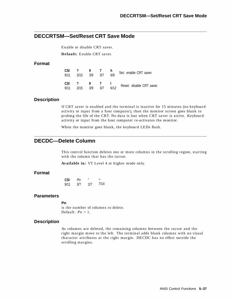
DECCRTSM—Set/Reset CRT Save Mode
DECCRTSM—Set/Reset CRT Save Mode
Enable or disable CRT saver.
Default: Enable CRT saver.
Format
CSI9/11
?3/15
93/9
73/7
h6/8
Set: enable CRT saver.
CSI9/11
?3/15
93/9
73/7
l6/12
Reset: disable CRT saver.
Description
If CRT saver is enabled and the terminal is inactive for 15 minutes (no keyboardactivity or input from a host computer), then the monitor screen goes blank toprolong the life of the CRT. No data is lost when CRT saver is active. Keyboardactivity or input from the host computer re-activates the monitor.
When the monitor goes blank, the keyboard LEDs flash.
DECDC—Delete Column
This control function deletes one or more columns in the scrolling region, startingwith the column that has the cursor.
Available in: VT Level 4 or higher mode only.
Format
CSI9/11
Pn3/?
’2/7
~7/14
Parameters
Pnis the number of columns to delete.Default: Pn = 1.
Description
As columns are deleted, the remaining columns between the cursor and theright margin move to the left. The terminal adds blank columns with no visualcharacter attributes at the right margin. DECDC has no effect outside thescrolling margins.
ANSI Control Functions 5–37

DECDHL—Double-Width, Double-Height Line
DECDHL—Double-Width, Double-Height Line
These two control functions make the line with the cursor the top or bottom halfof a double-height, double-width line. You must use these sequences in pairson adjacent lines. In other words, the same display characters must appear inthe same positions on both lines to form double-height characters. If the linewas single width and single height, then all characters to the right of the screencenter are lost.
Format
ESC1/11
#2/3
33/3
Top Half
ESC1/11
#2/3
43/4
Bottom Half
Description
The following sequences make the phrase ‘‘VT520 Video Terminal’’ a double-height, double-width line.
ESC#3 VT520 Video TerminalESC#4 VT520 Video Terminal
This control does not operate when DECLRMM (left right margin mode) is set.
5–38 ANSI Control Functions
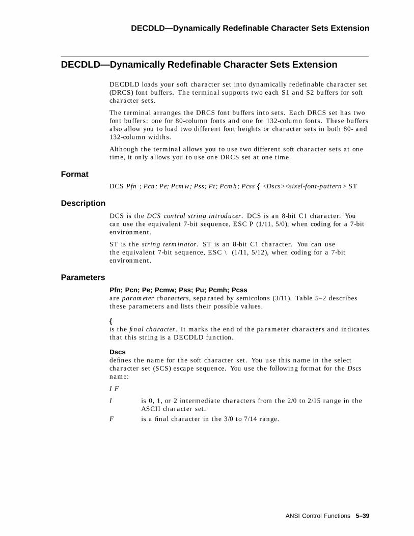
DECDLD—Dynamically Redefinable Character Sets Extension
DECDLD—Dynamically Redefinable Character Sets Extension
DECDLD loads your soft character set into dynamically redefinable character set(DRCS) font buffers. The terminal supports two each S1 and S2 buffers for softcharacter sets.
The terminal arranges the DRCS font buffers into sets. Each DRCS set has twofont buffers: one for 80-column fonts and one for 132-column fonts. These buffersalso allow you to load two different font heights or character sets in both 80- and132-column widths.
Although the terminal allows you to use two different soft character sets at onetime, it only allows you to use one DRCS set at one time.
FormatDCS Pfn ; Pcn; Pe; Pcmw; Pss; Pt; Pcmh; Pcss f <Dscs><sixel-font-pattern> ST
Description
DCS is the DCS control string introducer. DCS is an 8-bit C1 character. Youcan use the equivalent 7-bit sequence, ESC P (1/11, 5/0), when coding for a 7-bitenvironment.
ST is the string terminator. ST is an 8-bit C1 character. You can usethe equivalent 7-bit sequence, ESC \ (1/11, 5/12), when coding for a 7-bitenvironment.
Parameters
Pfn; Pcn; Pe; Pcmw; Pss; Pu; Pcmh; Pcssare parameter characters, separated by semicolons (3/11). Table 5–2 describesthese parameters and lists their possible values.
{is the final character. It marks the end of the parameter characters and indicatesthat this string is a DECDLD function.
Dscsdefines the name for the soft character set. You use this name in the selectcharacter set (SCS) escape sequence. You use the following format for the Dscsname:
I F
I is 0, 1, or 2 intermediate characters from the 2/0 to 2/15 range in theASCII character set.
F is a final character in the 3/0 to 7/14 range.
ANSI Control Functions 5–39
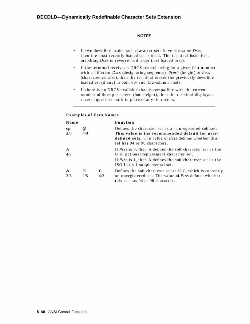
DECDLD—Dynamically Redefinable Character Sets Extension
NOTES
• If two downline loaded soft character sets have the same Dscs,then the most recently loaded set is used. The terminal looks for amatching Dscs in reverse load order (last loaded first).
• If the terminal receives a DRCS control string for a given font numberwith a different Dscs (designating sequence), Pcmh (height) or Pcss(character set size), then the terminal erases the previously downlineloaded set (if any) in both 80- and 132-column mode.
• If there is no DRCS available that is compatible with the currentnumber of lines per screen (font height), then the terminal displays areverse question mark in place of any characters.
Examples of Dscs Names
Name Functionsp2/0
@4/0
Defines the character set as an unregistered soft set.This value is the recommended default for user-defined sets. The value of Pcss defines whether thisset has 94 or 96 characters.
A4/2
If Pcss is 0, then A defines the soft character set as theU.K. national replacement character set.If Pcss is 1, then A defines the soft character set as theISO Latin-1 supplemental set.
&2/6
%2/5
C4/3
Defines the soft character set as % C, which is currentlyan unregistered set. The value of Pcss defines whetherthis set has 94 or 96 characters.
5–40 ANSI Control Functions

DECDLD—Dynamically Redefinable Character Sets Extension
Table 5–2 DECDLD Parameter Characters
Parameter Name Description
Pfn Font number Selects the DRCS (soft character set) to load.The previous set (if any), that you load withthat font number, is erased or overwritten asspecified by the control sequence.
You can assign a value of 0, 1, and 2 to Pfn.Other values cause the terminal to ignore theentire sequence. Pfn = 0 defaults to the firstempty font buffer, or, if none are empty, to fontbuffer 1.
Pcn Startingcharacter
Selects where to load the first character in theDRCS font buffer. The location correspondsto a location in the ASCII code table. Forexample, a Pcn value of 0 means that the firstsoft character is loaded into position 2/0 of thecharacter table. A Pcn value of 1 means position2/1 in the table, and so on, up toPcn = 95 (position 7/15).Pcn is affected by the character set size. SeePcss below.
Pe Erase control Selects which characters to erase from theDRCS buffer before loading the new font.0 = Erases all characters in the DRCS
buffer with this number, width, andrendition.
1 = Erases only characters in locationsbeing reloaded.
2 = Erases all renditions of the softcharacter set (normal, bold, 80-column, 132-column).
Note
Erased characters are undefined (notblank). The terminal displays thesecharacters as the error character (reversequestion mark).
(continued on next page)
ANSI Control Functions 5–41

DECDLD—Dynamically Redefinable Character Sets Extension
Table 5–2 (Cont.) DECDLD Parameter Characters
Parameter Name Description
Pcmw Charactermatrix width
Selects the maximum character cell width.When Pss specifies 80 columns, Pu specifies fontusage full cell as follows:0 = 10 pixels wide for 80 columns,
6 pixels wide for 132 columns.(default).
0 = device default2 = 5 � 10 pixel cell (width � height).3 = 6 � 10 pixel cell (width � height).4 = 7 � 10 pixel cell (width � height).5 = 5 pixels wide.6 = 6 pixels wide.7 = 7 pixels wide.8 = 8 pixels wide.9 = 9 pixels wide.
10 = 10 pixels wide.When Pss specifies 80 columns, Pu specifies fontusage text as follows:0 = 10 pixels wide for 80 columns,
6 pixels wide for 132 columns.(default)
0 = device default2 = 5 � 10 pixel cell (width � height).3 = 6 � 10 pixel cell (width � height).4 = 7 � 10 pixel cell (width � height).5 = 5 pixels wide....9 = 9 pixels wide.When Pss specifies 132 columns, Pu specifiesfont usage full cell as follows:0 = 10 pixels wide for 80 columns,
6 pixels wide for 132 columns.(default)
2 = 5 � 10 pixel cell (width � height).3 = 6 � 10 pixel cell (width � height).4 = 7 � 10 pixel cell (width � height).5 = 5 pixels wide.6 = 6 pixels wide.
(continued on next page)
5–42 ANSI Control Functions

DECDLD—Dynamically Redefinable Character Sets Extension
Table 5–2 (Cont.) DECDLD Parameter Characters
Parameter Name Description
When Pss specifies 132 columns, Pu specifiesfont usage text as follows:0 = 10 pixels wide for 80 columns,
6 pixels wide for 132 columns.(default)
2 = 5 � 10 pixel cell (width � height).3 = 6 � 10 pixel cell (width � height).4 = 7 � 10 pixel cell (width � height).5 = 5 pixels wide.If you omit a Pcmw value, the terminal uses thedefault character width. If the Pe parameteris 0, Pcmw must be less than 10. Any Pcmwvalue over 10 is illegal. For illegal values ofPcmw, the terminal ignores the rest of the loadsequence.
For VT200 compatible software: Use a Pcmw value of 0=device default,8 . . . 16 pixel high matrix.
Pss Font set size Defines the screen width and screen height forthis font.0,1 = 80 columns, 24 lines. (default)
0 = 80 columns, 24 lines1 = 80 columns, 24 (25 or 26) lines2 = 132 columns, 24 lines
11 = 80 columns, 36 (40 or 42) lines12 = 132 columns, 36 lines21 = 80 columns, 48 (50 or 52) lines11 = 132 columns, 48 lines
For illegal values of Pss, the terminal ignoresthe rest of the load sequence.If the number of columns or lines/screenchanges, then the terminal uses the appropriatevariation of the soft set. If you try to displaya DRCS character when there is no soft setdefined for the current number of lines andcolumns, then the terminal displays the errorcharacter (reverse question mark).
Note
For VT220 compatibility, you must use a soft font of 80 or132 columns (not both). The VT220 allows a single font tobe used for 80 and 132 columns.
(continued on next page)
ANSI Control Functions 5–43

DECDLD—Dynamically Redefinable Character Sets Extension
Table 5–2 (Cont.) DECDLD Parameter Characters
Parameter Name Description
You can load a font for any of the six sizes atany time. When a new soft set is loaded, anycharacters from the previous soft set are lost.Characters currently displayed from the old setbecome reverse question marks.
Pu Text or fullcell
Defines the font as a text font or full-cell font.0 = text. (default)1 = text.2 = full cell.Full-cell fonts can individually address all pixelsin a cell.Text fonts cannot individually address all pixels.If you specify a text cell, then the terminalautomatically performs spacing and centering ofthe characters.
Pcmh Charactermatrixheight
Selects the maximum character cell height.0 or omitted = 16 pixels high. (default)1 = 1 pixel high.8 = 8 pixels high.9 = 9 pixels high.
.
.
.16 = 16 pixels high.Pcmh values over 16 are illegal. If the value ofPcmw is 2, 3, or 4, then Pcmh is ignored.
5–44 ANSI Control Functions
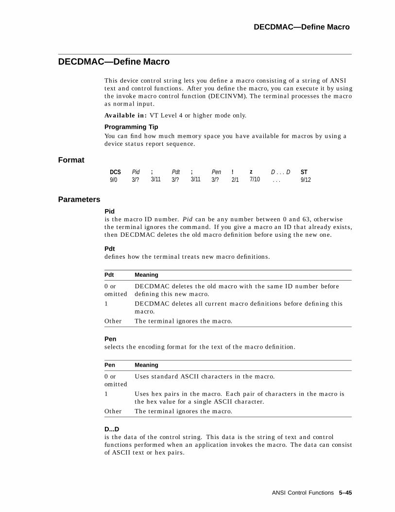
DECDMAC—Define Macro
DECDMAC—Define Macro
This device control string lets you define a macro consisting of a string of ANSItext and control functions. After you define the macro, you can execute it by usingthe invoke macro control function (DECINVM). The terminal processes the macroas normal input.
Available in: VT Level 4 or higher mode only.
Programming TipYou can find how much memory space you have available for macros by using adevice status report sequence.
Format
DCS9/0
Pid3/?
;3/11
Pdt3/?
;3/11
Pen3/?
!2/1
z7/10
D . . . D. . .
ST9/12
Parameters
Pidis the macro ID number. Pid can be any number between 0 and 63, otherwisethe terminal ignores the command. If you give a macro an ID that already exists,then DECDMAC deletes the old macro definition before using the new one.
Pdtdefines how the terminal treats new macro definitions.
Pdt Meaning
0 oromitted
DECDMAC deletes the old macro with the same ID number beforedefining this new macro.
1 DECDMAC deletes all current macro definitions before defining thismacro.
Other The terminal ignores the macro.
Penselects the encoding format for the text of the macro definition.
Pen Meaning
0 oromitted
Uses standard ASCII characters in the macro.
1 Uses hex pairs in the macro. Each pair of characters in the macro isthe hex value for a single ASCII character.
Other The terminal ignores the macro.
D...Dis the data of the control string. This data is the string of text and controlfunctions performed when an application invokes the macro. The data can consistof ASCII text or hex pairs.
ANSI Control Functions 5–45

DECDMAC—Define Macro
When you use ASCII text (Pen = 0 or omitted), the macro consists of thegraphic characters that appear in the device control string. Only characters frompositions 2/0 through 7/14 and 10/00 through 15/15 in the code table are valid.
When you use hex pairs (Pen = 1), the macro consists of pairs of hex numbers,each of which represents an ASCII character. When using hex pairs, you canalso use a repeat introducer in the data string. The repeat introducer is the !(2/1) character. The repeat introducer lets you repeat any hex pair within thedefinition string any number of times. You embed repeat sequences within thedata string of the macro definition.
Notes on DECDMAC
• If ASCII text is specified as the encoding format, then you cannot use therepeat sequence.
• ! is the repeat sequence introducer. The format of the hex string with therepeat introducer is as follows:
! Pn; D...D ;
Pn is a numeric parameter that specifies the number of times to repeatthe sequence. If Pn is omitted, then the macro repeats the sequence once.
D...D is the sequence of hex pairs to repeat Pn times.
A semicolon ; (3/11) separates the repeat count from the sequence ofhex pairs. Another semicolon ends the sequence. If any characters areincluded before the first semicolon, then the terminal ignores the macro.If a string terminator is placed before the final semicolon, then the repeatstring ends normally.
• The VT520 has 6 Kbytes of memory available for the storage of macros. Theterminal ignores any macro definitions that cannot fit into this space.
• A reset to initial state (RIS) or secure reset (DECSR) operation clears allmacro definitions. A soft terminal reset (DECSTR) has no effect on storedmacro definitions.
• You can include characters from positions 0/8 through 0/13 to format thedevice control string, but these characters cannot be part of the macrodefinition.
5–46 ANSI Control Functions

DECDLDA—Down Line Load Allocation
DECDLDA—Down Line Load Allocation
This control function controls the number of soft character sets (DECS) allowedper session.
Available for: monochrome terminals only; not available for color terminals.
Format
CSI9/11
Ps3/s
,2/12
z7/10
Parameters
Psis the number of soft character sets allowed:Default: Ps = 2.
Ps Description Compatible with terminals such as . . .
1 One each VT420 video terminal.2 Two each for sessions S1
and S2VT510 video terminal.
Description
For the monochrome monitor, you can use these commands to set up one or twosoft character sets for sessions S1 and S2. You can also use the Session . Softcharacter sets/session to perform this same function. Also see 2.6.4.
The color terminal does not use this command because it has enough memory togive all four sessions Two each.
DECDLDA can be reported using DECRPSS.
ANSI Control Functions 5–47
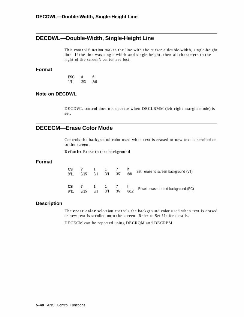
DECDWL—Double-Width, Single-Height Line
DECDWL—Double-Width, Single-Height Line
This control function makes the line with the cursor a double-width, single-heightline. If the line was single width and single height, then all characters to theright of the screen’s center are lost.
Format
ESC1/11
#2/3
63/6
Note on DECDWL
DECDWL control does not operate when DECLRMM (left right margin mode) isset.
DECECM—Erase Color Mode
Controls the background color used when text is erased or new text is scrolled onto the screen.
Default: Erase to text background
Format
CSI9/11
?3/15
13/1
13/1
73/7
h6/8
Set: erase to screen background (VT)
CSI9/11
?3/15
13/1
13/1
73/7
l6/12
Reset: erase to text background (PC)
Description
The erase color selection controls the background color used when text is erasedor new text is scrolled onto the screen. Refer to Set-Up for details.
DECECM can be reported using DECRQM and DECRPM.
5–48 ANSI Control Functions

DECEKBD—Extended Keyboard Report
DECEKBD—Extended Keyboard Report
This control function is a report that provides applications with more completekeystroke information. Each report consists of an ISO key position code and thecurrent state of the eight modifier keys—pressed or released.
Format
APC9/15
:3/10
ppp***
mm**
ST9/12
Parameters
pppis a three-character ISO key position name, for example C01. For keys thatoccupy more than one position in the ISO key position map, the VT520 uses thelargest lower-left position. The position for the space bar is A02; Return is C13.
mmare two ASCII hexadecimal digits that represent the state of the modifier keys.
The terminal represents the state of each modifier key as a bit in an 8-bit binarynumber. A bit value of 1 means the key is pressed, and a bit value of 0 meansthe key is not pressed. mm is the hexadecimal equivalent of the resulting 8-bitbinary number.
The following table shows the order in which keys are represented in the binarynumber, and their corresponding hexadecimal values when pressed. The leastsignificant bit represents the left Shift key. The most significant bit represents theright Compose Character key.
For example, 000000102 means that the right Shift key is pressed. Thehexadecimal value for 000000102 is 0216.
mm Key
01 left Shift (Least significant bit)02 right Shift
04 Lock
08 Ctrl
10 left Alt Function
20 right Alt Function
40 left Compose Character
80 right Compose Character (Most significant bit)
ANSI Control Functions 5–49
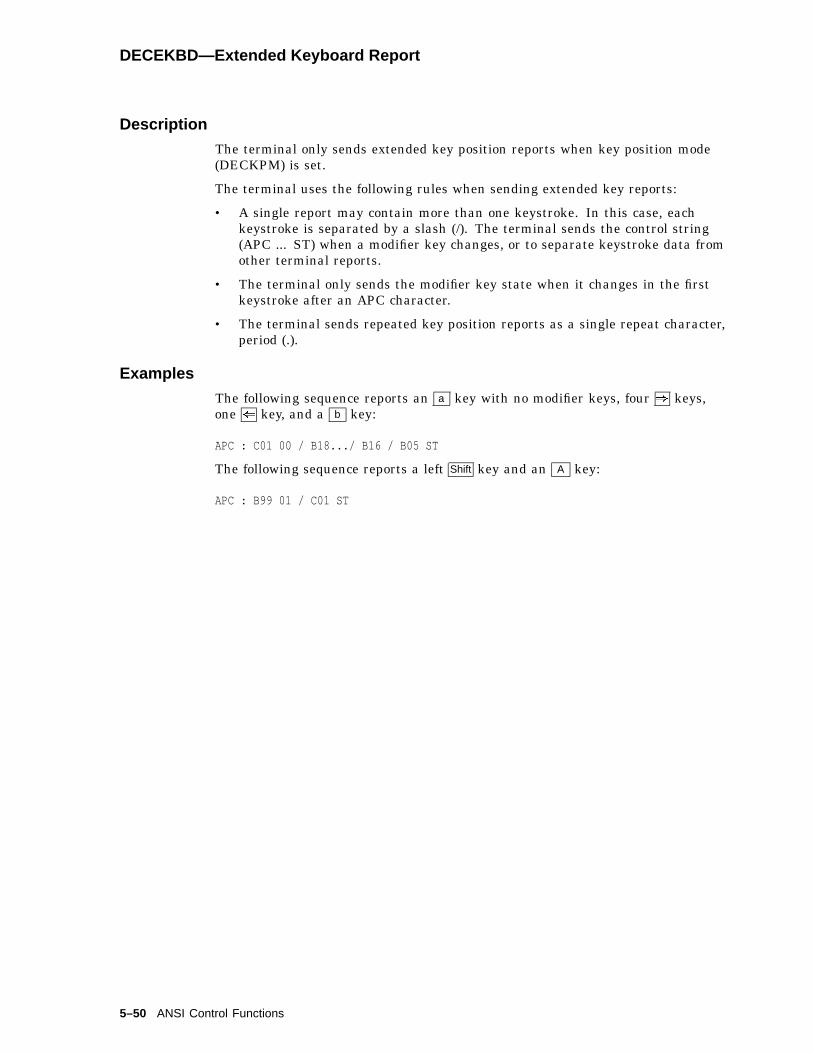
DECEKBD—Extended Keyboard Report
Description
The terminal only sends extended key position reports when key position mode(DECKPM) is set.
The terminal uses the following rules when sending extended key reports:
• A single report may contain more than one keystroke. In this case, eachkeystroke is separated by a slash (/). The terminal sends the control string(APC ... ST) when a modifier key changes, or to separate keystroke data fromother terminal reports.
• The terminal only sends the modifier key state when it changes in the firstkeystroke after an APC character.
• The terminal sends repeated key position reports as a single repeat character,period (.).
Examples
The following sequence reports an a key with no modifier keys, four ) keys,one ( key, and a b key:
APC : C01 00 / B18.../ B16 / B05 ST
The following sequence reports a left Shift key and an A key:
APC : B99 01 / C01 ST
5–50 ANSI Control Functions

DECELF—Enable Local Functions
DECELF—Enable Local Functions
This control function lets you enable or disable the keys used to perform severallocal terminal functions: cutting and pasting text, panning, and resizing windows.DECELF is useful for:
• Simplifying the keyboard for novice users
• Letting the corresponding keys send position codes to the host when keyposition mode (DECKPM) is set
• Disabling features that are not compatible with the application
Format
CSI9/11
Pf13/n
;3/11
Pc13/n
;3/11
. . .
. . .Pfn; Pcn3/n 3/n
+2/11
q7/1
Parameters
Pfnis a number that specifies the local function affected.
Pfn Local Functions Affected Default Setting
0 (default) All local functions listed for 1, 2, and 3.1 Copy and paste keys, including F1 (Hold),
Select , Remove , and Insert Here .The keys areenabled.
2 Panning keys, including Ctrl with * , + ,( , or ) .
The keys areenabled.
3 Window resizing keys, including: Control andShift with * or + keys.
The keys areenabled.
Pcncontrols the action of the local function specified by the corresponding Pfn value.
Pcn Meaning
0 Selects the default setting of the local function.In VT mode, the default setting is enabled.In PC Term mode, the default setting is disabled.
1 Enables the local function. The associated keys perform the localfunction and cannot send position codes to the host.
2 Disables the local function. The associated keys do not perform thelocal function and may send position codes to the host.
Description
DECELF can accept any number of parameter pairs. The terminal executes theparameters in the order in which it receives them.
ANSI Control Functions 5–51

DECERA—Erase Rectangular Area
DECERA—Erase Rectangular Area
This control function erases characters from the specified rectangular area inpage memory. When an area is erased, DECERA replaces all character positionswith the space character (2/0). DECERA erases character values and visualattributes from the specified area. DECERA does not erase line attributes.
Available in: VT Level 4 or higher mode only.
Format
CSI9/11
Pt3/n
;3/11
Pl; Pb; Pr********
$2/4
z7/10
Parameters
Pt, Pl, Pb, and Prdefine the rectangular area to be erased:
Pt is the top-line border. Pt must be less than or equal to Pb.Default: Pt = 1.
Pl is the left-column border. Pl must be less than or equal to Pr. Default: Pl= 1.
Pb is the bottom-line border.Default: Pb = the last line of the active page.
Pr is the right-column border.Default: Pr = the last column of the active page.
Notes on DECERA
• The coordinates of the rectangular area are affected by the setting of originmode (DECOM).
• DECERA is not affected by the page margins.
• If the value of Pt, Pl, Pb, or Pr exceeds the width or height of the active page,then the value is treated as the width or height of that page.
• DECERA does not change the active cursor position.
5–52 ANSI Control Functions

DECES—Enable Session
DECES—Enable Session
Make the session receiving this command the active session.
Format
CSI9/11
&2/6
x7/8
Description
This command makes the session receiving this command the active session forkeyboard input. Normally the active session for keyboard input is controlled bythe user pressing the Session key.
DECESKM—Enable Secondary Keyboard Language Mode
Select a secondary or primary keyboard language.
Format
CSI9/11
?3/15
13/1
03/0
43/4
h3/8
Secondary keyboard mapping.
CSI9/11
?3/15
13/1
03/0
43/4
l6/12
Primary keyboard mapping.
Description
When enabled, a secondary keyboard mapping (Group 2) replaces the primarykeyboard mapping. To use the secondary keyboard mapping, a secondarykeyboard language has to be defined for the currently selected keyboard language,such as Hebrew, Greek, or Cyrillic.
ANSI Control Functions 5–53

DECFI—Forward Index
DECFI—Forward Index
This control function moves the cursor forward one column. If the cursor is at theright margin, then all screen data within the margins moves one column to theleft. The column shifted past the left margin is lost.
Available in: VT Level 4 or higher mode only.
Format
ESC1/11
93/6
Description
DECFI adds a new column at the right margin, with no visual attributes. DECFIis not affected by the margins. If the cursor is at the right border of the pagewhen the terminal receives DECFI, then the terminal ignores DECFI.
5–54 ANSI Control Functions
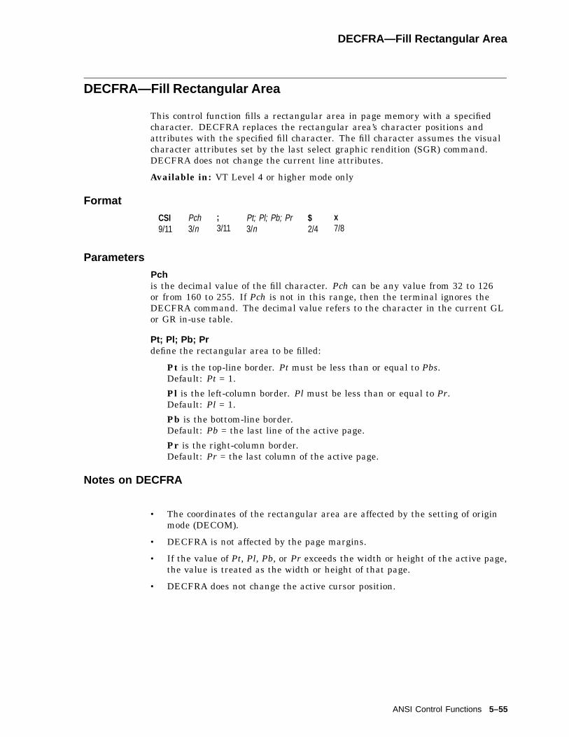
DECFRA—Fill Rectangular Area
DECFRA—Fill Rectangular Area
This control function fills a rectangular area in page memory with a specifiedcharacter. DECFRA replaces the rectangular area’s character positions andattributes with the specified fill character. The fill character assumes the visualcharacter attributes set by the last select graphic rendition (SGR) command.DECFRA does not change the current line attributes.
Available in: VT Level 4 or higher mode only
Format
CSI9/11
Pch3/n
;3/11
Pt; Pl; Pb; Pr3/n
$2/4
x7/8
Parameters
Pchis the decimal value of the fill character. Pch can be any value from 32 to 126or from 160 to 255. If Pch is not in this range, then the terminal ignores theDECFRA command. The decimal value refers to the character in the current GLor GR in-use table.
Pt; Pl; Pb; Prdefine the rectangular area to be filled:
Pt is the top-line border. Pt must be less than or equal to Pbs.Default: Pt = 1.
Pl is the left-column border. Pl must be less than or equal to Pr.Default: Pl = 1.
Pb is the bottom-line border.Default: Pb = the last line of the active page.
Pr is the right-column border.Default: Pr = the last column of the active page.
Notes on DECFRA
• The coordinates of the rectangular area are affected by the setting of originmode (DECOM).
• DECFRA is not affected by the page margins.
• If the value of Pt, Pl, Pb, or Pr exceeds the width or height of the active page,the value is treated as the width or height of that page.
• DECFRA does not change the active cursor position.
ANSI Control Functions 5–55

DECFWM—Set/Reset Framed Windows Mode
DECFWM—Set/Reset Framed Windows Mode
Selects whether or not session windows are displayed with window frames withframe borders and icons.
Default: Framed windows enabled
Format
CSI9/11
?3/15
13/1
13/1
13/1
h6/8
Set: enables framed windows
CSI9/11
?3/15
13/1
13/1
13/1
l6/12
Reset: disables framed windows
Description
When framed windows is selected, window frames with title bars are added toeach displayed window. Refer to Set-Up chapter for details.
DECFWM can be reported using DECRQM and DECRPM.
DECHDPXM—Set/Reset Half-Duplex Mode
Enables half-/full-duplex communication.
Format
CSI9/11
?3/15
13/1
03/0
33/3
h6/8
Set to half-duplex mode.
CSI9/11
?3/15
13/1
03/0
33/3
l6/12
Set to full-duplex mode.
Description
Full-duplex mode allows simultaneously two-way communication; half-duplexmode is limited to one-way communication at any given time. Half-duplexmode is available only in an RS232 line. Refer to Chapter 9 for details abouthalf-duplex mode communication protocol.
5–56 ANSI Control Functions

DECHEM—Hebrew Encoding Mode
DECHEM—Hebrew Encoding Mode
This control function sets the terminal’s character set mode to DEC (8-bit)multinational mode. On a reset, the sequence resets the terminal’s character setmode to (7-bit) national mode (NRC sets).
The terminal maintains DECHEM for the main display and status line separatelyin the same way as it maintains National Replacement Character Set Mode(DECNRCM).
Format
CSI9/11
?3/15
33/3
63/6
h6/8
Set
CSI9/11
?3/15
33/3
63/6
l6/12
Reset
ANSI Control Functions 5–57
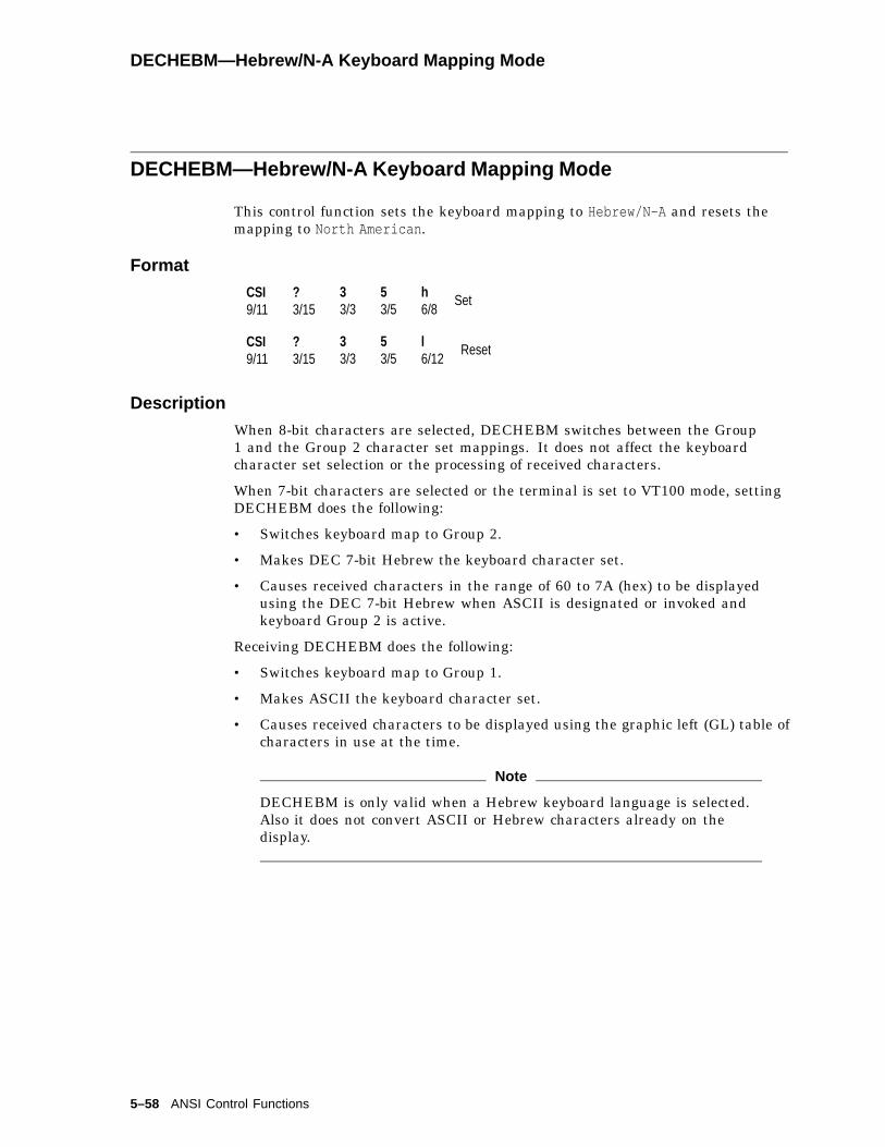
DECHEBM—Hebrew/N-A Keyboard Mapping Mode
DECHEBM—Hebrew/N-A Keyboard Mapping Mode
This control function sets the keyboard mapping to Hebrew/N-A and resets themapping to North American .
Format
CSI9/11
?3/15
33/3
53/5
h6/8
Set
CSI9/11
?3/15
33/3
53/5
l6/12
Reset
Description
When 8-bit characters are selected, DECHEBM switches between the Group1 and the Group 2 character set mappings. It does not affect the keyboardcharacter set selection or the processing of received characters.
When 7-bit characters are selected or the terminal is set to VT100 mode, settingDECHEBM does the following:
• Switches keyboard map to Group 2.
• Makes DEC 7-bit Hebrew the keyboard character set.
• Causes received characters in the range of 60 to 7A (hex) to be displayedusing the DEC 7-bit Hebrew when ASCII is designated or invoked andkeyboard Group 2 is active.
Receiving DECHEBM does the following:
• Switches keyboard map to Group 1.
• Makes ASCII the keyboard character set.
• Causes received characters to be displayed using the graphic left (GL) table ofcharacters in use at the time.
Note
DECHEBM is only valid when a Hebrew keyboard language is selected.Also it does not convert ASCII or Hebrew characters already on thedisplay.
5–58 ANSI Control Functions

DECHWUM—Host Wake-Up Mode (CRT and Energy Saver)
DECHWUM—Host Wake-Up Mode (CRT and Energy Saver)
When the Host wake-up feature is selected, any character received from the hostwill also restore the display.
Format
CSI9/11
?3/15
13/1
13/1
33/3
h6/8
Set: enables host wake-up mode
CSI9/11
?3/15
13/1
13/1
33/3
l6/12
Reset: disables host wake-up mode
Description
This command allows any character received from the host to restore the displaywhen either the CRT or Energy saver is in effect. Refer to Set-Up chapter fordetails.
DECHWUM can be reported using DECRPM.
DECIC—Insert Column
This control function inserts one or more columns into the scrolling region,starting with the column that has the cursor.
Available in: VT Level 4 or higher mode only
Format
CSI9/11
Pn3/?
’2/7
}7/13
Parameters
Pnis the number of columns to insert.Default: Pn = 1.
Description
As columns are inserted, the columns between the cursor and the right marginmove to the right. DECIC inserts blank columns with no visual characterattributes. DECIC has no effect outside the scrolling margins.
ANSI Control Functions 5–59
DECID—Identify Device
DECID—Identify Device
This control function is similar to a primary device attributes (DA) request fromthe host.
Note
Using DECID is not recommended. DECID may not be supported in themanufacturers terminals. You should use the primary device attributesrequest for this purpose. In VT400 or higher mode, the terminal ignoresDECID.
Format
ESC1/11
Z5/10
Terminal ResponseThe terminal uses the same response as for a primary DA request for alloperating levels (1 or 4). See DA1, DA2, and DA3.
5–60 ANSI Control Functions

DECINVM—Invoke Macro
DECINVM—Invoke Macro
This control function lets you execute a stored macro. You store macros withthe define macro (DECDMAC) control string. The terminal substitutes theDECINVM sequence with the contents of the macro definition and executes themacro.
Available in: VT Level 4 or higher mode only.
Format
CSI9/11
Pid3/n
*2/10
z7/10
Parameters
Pidis the macro ID number. If the Pid is not associated with a particular macro, theterminal ignores the command.
Notes on DECINVM
Any functions executed with a macro invocation remain in affect after theterminal executes the macro.
Examples
Suppose you want to create a macro that clears all pages in page memory, writesthe word "top" at the top of each page, and leaves the cursor on page 1.
First, you would write the string with ASCII characters as follows:
DCS 1 ; 0 ; 1 ! z CSI 6 sp P ! 6 ; CSI 1 ; 1 H CSI 2 J TOPCSI 1 V ; ST
Then, you must convert the string into hexadecimal code because the string usesthe repeat (!) character. You can only use the repeat character with hexadecimalsequences. The following example is the same string written in hex:
DCS 1 ; 0 ; 1 ! z 9B 36 20 50 ! 6 ; 9B 31 3B 48 9B 32 49 544F 50 9B 31 56 ; ST
To invoke the macro, use the following sequence:
CSI 1 * z
ANSI Control Functions 5–61
DECIPEM—Enter/Return from IBM ProPrinter Emulation Mode
DECIPEM—Enter/Return from IBM ProPrinter Emulation Mode
Exit from DEC protocol and interpret subsequent data according to the IBMProPrinter protocol syntax. This sequence also resets IBM ProPrinter mode to itsinitial state.
Format
CSI9/11
?3/15
53/5
83/8
h6/8
Set: Enter ProPrinter Emulation mode.
CSI9/11
?3/15
53/5
83/8
l6/12
Reset: Return from ProPrinter Emulation mode.
Description
DECIPEM works the same as the IBM SOCS and ROCS control functions.
5–62 ANSI Control Functions

DECKBD—Keyboard Language Selection
DECKBD—Keyboard Language Selection
Select a national keyboard language on either a VT keyboard or an Enhanced PCkeyboard.
Format
CSI9/11
Ps13/n
;3/
Ps23/n
SP2/0
}7/13
Parameters
Ps1denotes a keyboard type (layout): VT or enhanced PC.
Ps1 Keyboard Layout
0, 1, or None VT2 Enhanced PC
Ps2indicates the national keyboard language.
Ps2 Keyboard Language (VT/PC)
0, 1 or None North American2 British3 Belgian (Flemish)4 French Canadian5 Danish6 Finnish7 German8 Dutch9 Italian10 Swiss French11 Swiss German12 Swedish13 Norwegian14 French15 Spanish16 Portuguese19 Hebrew22 Greek28 Canadian (English)29 Turkish Q/Turkish30 Turkish F
ANSI Control Functions 5–63

DECKBD—Keyboard Language Selection
Ps2 Keyboard Language (VT/PC)
31 Hungarian33 Slovak34 Czech35 Polish36 Romanian38 SCS39 Russian40 Latin American
Description
The first selective parameter, Ps1, denotes a keyboard type, VT layout orEnhanced PC keyboard layout. The second parameter, Ps2, indicates the nationalkeyboard language.
Selecting a new keyboard language automatically initializes the keyboardcharacter set. Refer to Chapter 8 for more details.
5–64 ANSI Control Functions

DECKBUM—Typewriter or Data Processing Keys
DECKBUM—Typewriter or Data Processing Keys
You can select whether the main keyboard keys act as data processing keys ortypewriter keys by using the keyboard usage mode (DECKBUM) function.
Default: Typewriter keys
Keyboard Usage Mode (DECKBUM)
CSI9/11
?3/15
63/6
83/8
h6/8
Set: data processing keys.
CSI9/11
?3/15
63/6
83/8
l6/12
Reset: typewriter keys.
Description
If DECKBUM is set, then data processing keys send the characters on the righthalf of their keycaps.
If DECKBUM is reset, then data processing keys send the characters on the lefthalf of their keycaps.
Notes on DECKBUM
• DECKBUM changes the characters that the main keyboard keys send. Makesure you are aware of this change if you use DECKBUM in an application.
• If you use the North American language, then DECKBUM should always bereset (typewriter). For all other languages, you can use either mode.
DECKLHIM—Keyboard LED’s Host Indicator Mode
DECKLHIM controls the state of the keyboard LED’s host indicator mode.
Default: Reset.
Format
CSI9/11
?3/15
13/1
13/1
03/0
h6/8
Set: keyboard LED’s host indicator mode.
CSI9/11
?3/15
13/1
13/1
03/0
l6/12
Reset: The keyboard LED’s act as local indicators.
Description
See DECLL for the implications of using DECLL to control the keyboard LEDsindependently of any keyboard state.
ANSI Control Functions 5–65

DECKPAM—Keypad Application Modes
DECKPAM—Keypad Application Modes
DECKPAM enables the numeric keypad to send application sequences to the host.
See DECKPNM—Keypad Numeric Modes , which enables the numeric keypad tosend keypad characters.
DECKPAM and DECKPNM function the same as numeric keypad mode(DECNKM).
Format
ESC1/11
=3/13 Sends application sequences.
Note on DECKPAM
When you turn on or reset the terminal, it automatically selects numeric keypadmode.
DECKPM—Key Position Mode
This control function selects whether the keyboard sends character codes or keyposition reports to the host. DECKPM lets new applications take full controlof the keyboard including single shifts, locking shifts, and compose characterprocessing.
Default: Send character codes
Format
CSI9/11
83/8
13/1
h6/8
Set: send key position reports.
CSI9/11
83/8
13/1
l6/12
Reset: send character codes.
Description
If the DECKPM function is set, then all keyboard keys send extended reportsthat include the key position and the state of modifier keys when pressed. Amodifier key is pressed in combination with another key to modify the code sentby that key. The Ctrl key is a modifier key.
If the DECKPM function is reset, then the keyboard keys send character codes.
Note on DECKPM
DECKPM only affects keyboard input; it does not affect how the terminalinterprets data from the host.
5–66 ANSI Control Functions
DECKPNM—Keypad Numeric Modes
DECKPNM—Keypad Numeric Modes
DECKPNM enables the numeric keypad to send keypad characters to the host.
See DECKPAM—Keypad Application Modes , which enables the keypad to sendapplication sequences.
DECKPNM and DECKPAM function the same as numeric keypad mode(DECNKM).
Default: Send keypad characters.
Format
ESC1/11
>3/14 Send keypad characters.
Description
DECKPNM enables the numeric keypad to send the characters shown on eachkey—number, comma, period, or minus sign. Keys PF1 to PF4 send applicationsequences. See DECKPAM—Keypad Application Modes for more information.
Note on DECKPNM
When you turn on or reset the terminal, it automatically selects numeric keypadmode.
ANSI Control Functions 5–67
DECLANS—Load Answerback Message
DECLANS—Load Answerback Message
This sequence loads an answerback message into the terminal’s memory.
Format
DCS9/0
Psps
v7/6
D . . . D. . .
ST9/12
Description
The answerback data string may consist of from 0 to 30, 7- or 8-bit characters,which are hex pairs in the range:
3/0 - 3/9 (0 through 9),4/1 - 4/6 (A through F), and6/1 - 6/6 (a through f).
Once defined, the message may be stored in the non-volatile memory if Savesettings is executed in the Set-Up.
The selective parameter denotes the encoding of the answerback message. A "1"is always used for the VT520 indicating answerback is encoded as hex pairs. Thesequence is ignored if any number other than "1" is specified in the Ps field.
Pressing Ctrl/Break or receiving ENQ code causes the VT520 to transmit theanswerback message. In on-line mode, the answerback message is transmitted tothe appropriate host port. The answerback is not echoed in local echo and is not"sent" in local mode.
The answerback message is transmitted as keyboard data. Any speed restrictions(as set in limited transmit) apply.
5–68 ANSI Control Functions

DECLBAN—Load Banner Message
DECLBAN—Load Banner Message
DECLBAN loads a banner message to be displayed.
Format
DCS9/0
Ps3/s
r7/2
D . . . D. . .
ST9/12
Parameters
Psdenotes the encoding of the message.
Ps Description
0 Zero or omitted, default to Ps=2.1 Interprets as ASCII hexadecimal pairs. See DECLANS.2 Loads as text in the VT default character set.
D . . . Dis a 30-character string. If a matching Ps value is selected as an encodingmethod, then you can select to define the string by the characters in the defaultcharacter set or by hexadecimal pairs.
Description
DECLBAN loads a banner message to be displayed at terminal power-on. Oncedefined, the user must store the banner message in non-volatile memory byinvoking Save settings in order for it to be available at power-on. The terminaldisplays the banner message in double size characters above the Selftest OKmessage.
ANSI Control Functions 5–69

DECLFKC—Local Function Key Control
DECLFKC—Local Function Key Control
This control function lets you select the action performed by some of the localfunction keys on the top row of the keyboard:
Pk Function VT Keyboard Enhanced PC Keyboard
1 Hold F1 Scroll Lock
2 Print F2 Print Screen
3 Set-Up F3 Caps Lock/Print Screen
You can have the key perform its local function, send a function key sequence tothe host, or do nothing.
This control function is useful for:
• Simplifying the keyboard for novice users
• Disabling features that are not compatible with the application, such as localprinting
Format
CSI9/11
Pk13/n
;3/11
Pf13/n
. . .
. . .Pkn3/n
;3/11
Pfn3/n
*2/10
}7/13
Parameters
Pknis a number from 0 to 4 that corresponds to the local function key affected ( F1 to
F4 ). A Pkn value of 0 means that all four keys ( F1 through F4 ) are affected.
Pfncontrols the action of the local function key specified by the corresponding Pknvalue.
Pfn Meaning VT Mode PCTerm Mode
0 Selects the defaultfunction of the key.
Local print Scan code
1 The key performs itslocal function eithershifted, unshifted, orwith the Ctrl key.
Print Local Print
2 The unshifted keysends its functionkey sequence to thehost. The key sendsnothing when pressedwith Shift or Ctrl .
Function Key Scan Code
3 The key is disabled. Disabled Does not exist
5–70 ANSI Control Functions

DECLFKC—Local Function Key Control
Description
DECLFKC can accept any number of parameter pairs. The terminal executes theparameters in the order in which it receives them.
Note on DECLFKC
Applications cannot disable the F5 (Break) key. This restriction is required forsecure systems, which ensures that the operator has control of the communicationline.
DECLL—Load LEDs
Load the programmable LEDs on the keyboard according to its parameters.
Format
CSI9/11
Ps3/n
q7/1
Parameters
Psselects the state of the Num Lock , Caps Lock , and Scroll Lock LEDs as follows:
Ps LED Light Condition
0 Num Lock
Caps Lock
Scroll Lock
OffOffOff
1 Num Lock On2 Caps Lock On3 Scroll Lock On21 Num Lock Off22 Caps Lock Off23 Scroll Lock Off
ANSI Control Functions 5–71

DECLRMM—Left Right Margin Mode
DECLRMM—Left Right Margin Mode
This control function defines whether or not the set left and right margins(DECSLRM) control function can set margins.
Available in: VT Level 4 or higher mode only.Default: DECSLRM cannot set margins.
Format
CSI9/11
?3/15
63/6
93/9
h6/8
Set: DECSLRM can set margins.
CSI9/11
?3/15
63/3
93/9
l6/12
Reset: DECSLRM cannot set margins.
Description
When DECLRMM is set, DECSLRM can set the left and right margins. All lineattributes currently in page memory for the session are set to single width, singleheight. The terminal ignores any sequences to change the line attributes todouble width or double height (DECDWL or DECDHL).
When DECLRMM is reset, DECSLRM cannot set the left and right margins.The margins are set to the page borders for every page. The terminal canprocess sequences to change the line attributes to double width or double height(DECDWL or DECDHL).
DECLTOD—Load Time of Day
Down-line load the time of day on the terminal. This sequence loads the time ofday into the terminal’s memory.
Format
CSI9/11
Ps13/n
;3/11
Ps23/n
,2/12
p7/0
Parameters
Ps1specifies the hour, which is a 2-digit decimal number between 00 and 23.
The default value is 8, indicating 8:00 a.m.
Ps2specifies the minutes, which is a 2-digit decimal number between 00 and 59.
The default value is 00, indicating 8:00 a.m.
5–72 ANSI Control Functions
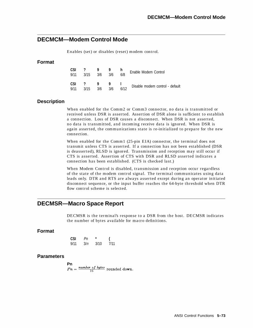
DECMCM—Modem Control Mode
DECMCM—Modem Control Mode
Enables (set) or disables (reset) modem control.
Format
CSI9/11
?3/15
93/6
93/6
h6/8
Enable Modem Control
CSI9/11
?3/15
93/6
93/6
l6/12
Disable modem control - default
Description
When enabled for the Comm2 or Comm3 connector, no data is transmitted orreceived unless DSR is asserted. Assertion of DSR alone is sufficient to establisha connection. Loss of DSR causes a disconnect. When DSR is not asserted,no data is transmitted, and incoming receive data is ignored. When DSR isagain asserted, the communications state is re-initialized to prepare for the newconnection.
When enabled for the Comm1 (25-pin EIA) connector, the terminal does nottransmit unless CTS is asserted. If a connection has not been established (DSRis deasserted), RLSD is ignored. Transmission and reception may still occur ifCTS is asserted. Assertion of CTS with DSR and RLSD asserted indicates aconnection has been established. (CTS is checked last.)
When Modem Control is disabled, transmission and reception occur regardlessof the state of the modem control signal. The terminal communicates using dataleads only. DTR and RTS are always asserted except during an operator initiateddisconnect sequence, or the input buffer reaches the 64-byte threshold when DTRflow control scheme is selected.
DECMSR—Macro Space Report
DECMSR is the terminal’s response to a DSR from the host. DECMSR indicatesthe number of bytes available for macro definitions.
Format
CSI9/11
Pn3/n
*3/10
{7/11
Parameters
PnPn =
number of bytes16 rounded down:
ANSI Control Functions 5–73

DECNAKB—Greek/N-A Keyboard Mapping Mode
DECNAKB—Greek/N-A Keyboard Mapping Mode
This control function sets the keyboard mapping to North American and resetsthe mapping to Greek/N-A .
Format
CSI9/11
?3/15
53/5
73/7
h6/8
Set.
CSI9/11
?3/15
53/5
73/7
l6/12
Reset.
DECNCSM—No Clearing Screen On Column Change Mode
Set/reset the following condition: do not clear the screen whenever the columnmode changes.
Format
CSI9/11
?3/15
93/9
53/5
h6/8
Set: do not clear screen when column mode changes.
CSI9/11
?3/15
93/9
53/5
l6/12
Reset: clear the screen when column mode changes.
Description
When enabled, a column mode change (either through Set-Up or by the escapesequence DECCOLM) does not clear the screen. When disabled, the column modechange clears the screen as a side effect.
This sequence does not affect the column mode change caused by the sequence,DECSCPP.
5–74 ANSI Control Functions

DECNKM—Numeric Keypad Mode
DECNKM—Numeric Keypad Mode
This control function works like the DECKPAM and DECKPNM functions.DECNKM is provided mainly for use with the request and report mode(DECRQM/DECRPM) control functions.
Available in: VT Level 4 or higher mode only
Default: Numeric
Format
CSI9/11
?3/15
63/6
63/6
h6/8
Set: application sequences.
CSI9/11
?3/15
63/6
63/6
l6/12
Reset: keypad characters.
DECNRCM—National Replacement Character Set Mode
Enable operation in 7-bit or 8-bit character mode.
Format
CSI9/11
?3/15
43/4
23/2
h6/8
Set: 7-bit characters.
CSI9/11
?3/15
43/4
23/2
l6/12
Reset: 8-bit characters (default)
Description
On the VT520, the character set mode is reset to 8-bit characters. In 8-bit mode,the terminal operates as a normal level 5 terminal allowing 8-bit controls andusing the default character set, which is user-selectable for transmission andreception.
ANSI Control Functions 5–75

DECNULM—Null Mode
DECNULM—Null Mode
Discard NUL characters upon receipt, or pass them on to the printer.
Format
CSI9/11
?3/15
13/1
03/0
23/2
h6/8
Set: discard NUL characters (default).
CSI9/11
?3/15
13/1
03/0
23/2
l6/12
Reset: pass NUL characters to printer.
Description
If enabled, the NUL character is discarded upon receipt and may be used as atime fill character. If disabled, then the NUL character is accepted and stored inthe input buffer so it may be passed on to the printer port.
DECNUMLK—Num Lock Mode
Controls the keyboard Num Lock state as if the Num Lock key had been pressed.
Format
CSI9/11
?3/15
13/1
03/0
83/8
h6/8
Set: Num lock ON.
CSI9/11
?3/15
13/1
03/0
83/8
l6/12
Reset: Num lock OFF.
5–76 ANSI Control Functions

DECOM—Origin Mode
DECOM—Origin Mode
This control function sets the origin for the cursor. DECOM determines if thecursor position is restricted to inside the page margins. When you power up orreset the terminal, you reset origin mode.
Default: Origin is at the upper-left of the screen, independent of margins.
Format
CSI9/11
?3/15
63/6
h6/8
Set: within margins.
CSI9/11
?3/15
63/3
l6/12
Reset: upper-left corner.
Description
When DECOM is set, the home cursor position is at the upper-left corner of thescreen, within the margins. The starting point for line numbers depends on thecurrent top margin setting. The cursor cannot move outside of the margins.
When DECOM is reset, the home cursor position is at the upper-left corner of thescreen. The starting point for line numbers is independent of the margins. Thecursor can move outside of the margins.
DECOSCNM—Set/Reset Overscan Mode (VT520 only)
Sets or resets overscan mode for monochrome terminal. (This feature is notavailable for color terminals.)
Default: Overscan disabled (reset).
Format
CSI9/11
?3/15
13/1
03/0
63/6
h6/8
Set: Enable overscan
CSI9/11
?3/15
13/1
03/0
63/6
l6/12
Reset: Disable overscan (Default)
ANSI Control Functions 5–77
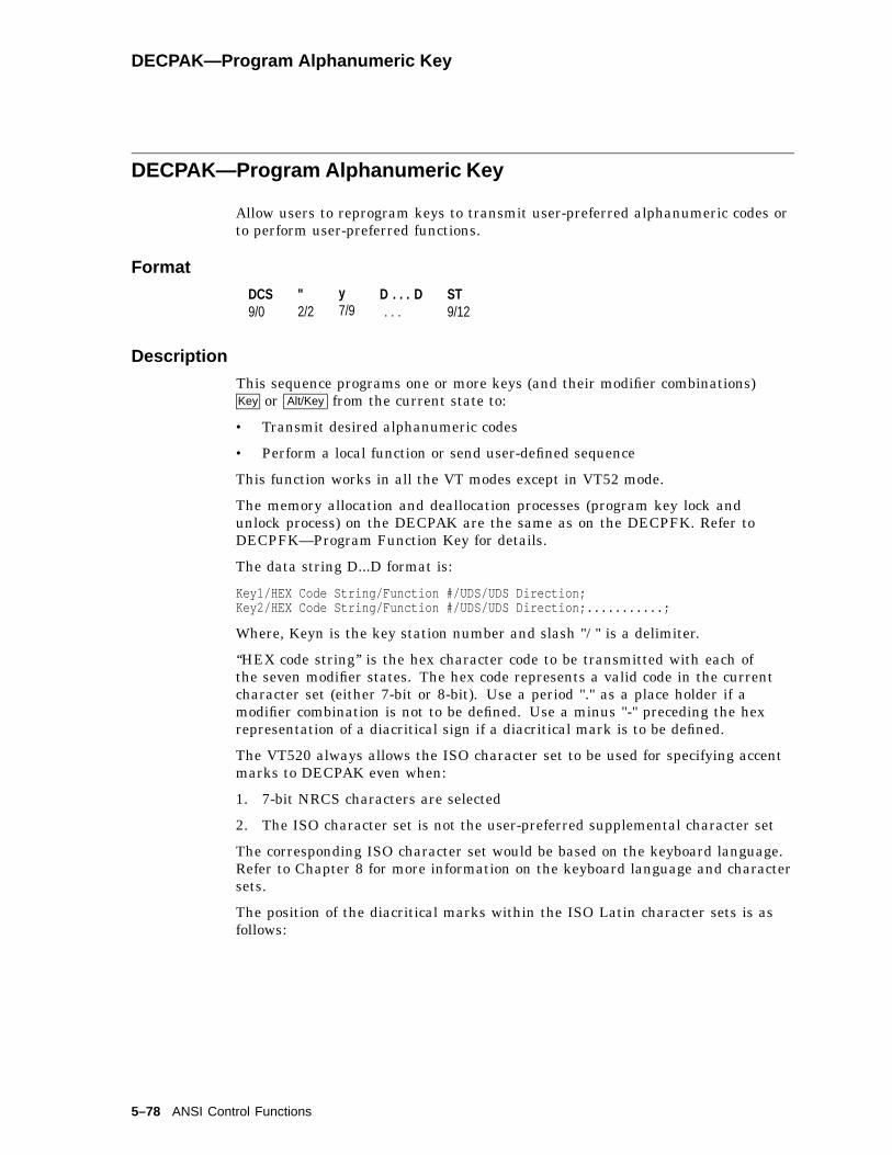
DECPAK—Program Alphanumeric Key
DECPAK—Program Alphanumeric Key
Allow users to reprogram keys to transmit user-preferred alphanumeric codes orto perform user-preferred functions.
Format
DCS9/0
"2/2
y7/9
D . . . D. . .
ST9/12
Description
This sequence programs one or more keys (and their modifier combinations)Key or Alt/Key from the current state to:
• Transmit desired alphanumeric codes
• Perform a local function or send user-defined sequence
This function works in all the VT modes except in VT52 mode.
The memory allocation and deallocation processes (program key lock andunlock process) on the DECPAK are the same as on the DECPFK. Refer toDECPFK—Program Function Key for details.
The data string D...D format is:
Key1/HEX Code String/Function #/UDS/UDS Direction;Key2/HEX Code String/Function #/UDS/UDS Direction;...........;
Where, Keyn is the key station number and slash "/ " is a delimiter.
‘‘HEX code string’’ is the hex character code to be transmitted with each ofthe seven modifier states. The hex code represents a valid code in the currentcharacter set (either 7-bit or 8-bit). Use a period "." as a place holder if amodifier combination is not to be defined. Use a minus "-" preceding the hexrepresentation of a diacritical sign if a diacritical mark is to be defined.
The VT520 always allows the ISO character set to be used for specifying accentmarks to DECPAK even when:
1. 7-bit NRCS characters are selected
2. The ISO character set is not the user-preferred supplemental character set
The corresponding ISO character set would be based on the keyboard language.Refer to Chapter 8 for more information on the keyboard language and charactersets.
The position of the diacritical marks within the ISO Latin character sets is asfollows:
5–78 ANSI Control Functions
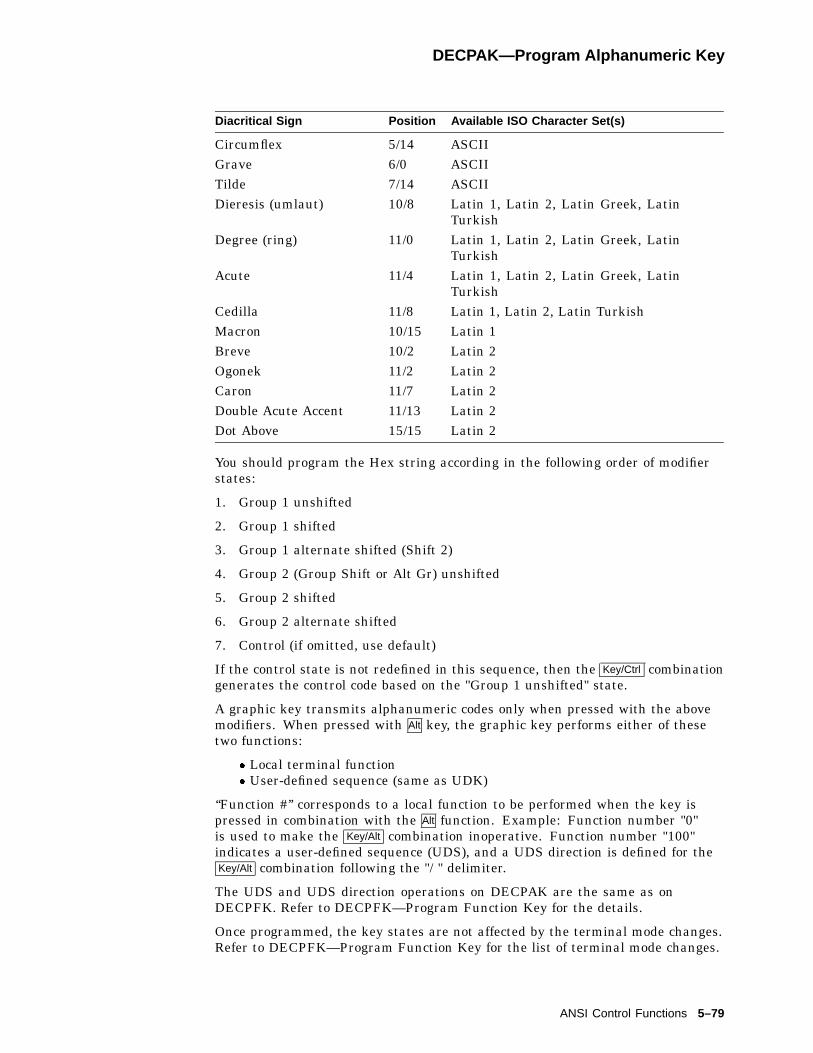
DECPAK—Program Alphanumeric Key
Diacritical Sign Position Available ISO Character Set(s)
Circumflex 5/14 ASCIIGrave 6/0 ASCIITilde 7/14 ASCIIDieresis (umlaut) 10/8 Latin 1, Latin 2, Latin Greek, Latin
TurkishDegree (ring) 11/0 Latin 1, Latin 2, Latin Greek, Latin
TurkishAcute 11/4 Latin 1, Latin 2, Latin Greek, Latin
TurkishCedilla 11/8 Latin 1, Latin 2, Latin TurkishMacron 10/15 Latin 1Breve 10/2 Latin 2Ogonek 11/2 Latin 2Caron 11/7 Latin 2Double Acute Accent 11/13 Latin 2Dot Above 15/15 Latin 2
You should program the Hex string according in the following order of modifierstates:
1. Group 1 unshifted
2. Group 1 shifted
3. Group 1 alternate shifted (Shift 2)
4. Group 2 (Group Shift or Alt Gr) unshifted
5. Group 2 shifted
6. Group 2 alternate shifted
7. Control (if omitted, use default)
If the control state is not redefined in this sequence, then the Key/Ctrl combinationgenerates the control code based on the "Group 1 unshifted" state.
A graphic key transmits alphanumeric codes only when pressed with the abovemodifiers. When pressed with Alt key, the graphic key performs either of thesetwo functions:
� Local terminal function� User-defined sequence (same as UDK)
‘‘Function #’’ corresponds to a local function to be performed when the key ispressed in combination with the Alt function. Example: Function number "0"is used to make the Key/Alt combination inoperative. Function number "100"indicates a user-defined sequence (UDS), and a UDS direction is defined for theKey/Alt combination following the "/ " delimiter.
The UDS and UDS direction operations on DECPAK are the same as onDECPFK. Refer to DECPFK—Program Function Key for the details.
Once programmed, the key states are not affected by the terminal mode changes.Refer to DECPFK—Program Function Key for the list of terminal mode changes.
ANSI Control Functions 5–79

DECPCCM—Page Cursor-Coupling Mode
DECPCCM—Page Cursor-Coupling Mode
This control function determines if a new page appears in the display when thecursor moves to a new page. DECPCCM is only useful with a multiple-pageformat.
Format
CSI9/11
?3/15
63/6
44/4
h6/8
Set: couples the cursor to the display.
CSI9/11
?3/15
63/6
44/4
l6/12
Reset: uncouples the cursor.
Description
When DECPCCM is set, the cursor is coupled to the display when the cursormoves to a new page. The new page appears in the display to keep the cursor inview.
When DECPCCM is reset, the cursor is uncoupled from the display. If the cursormoves to a new page, then the cursor disappears.
5–80 ANSI Control Functions
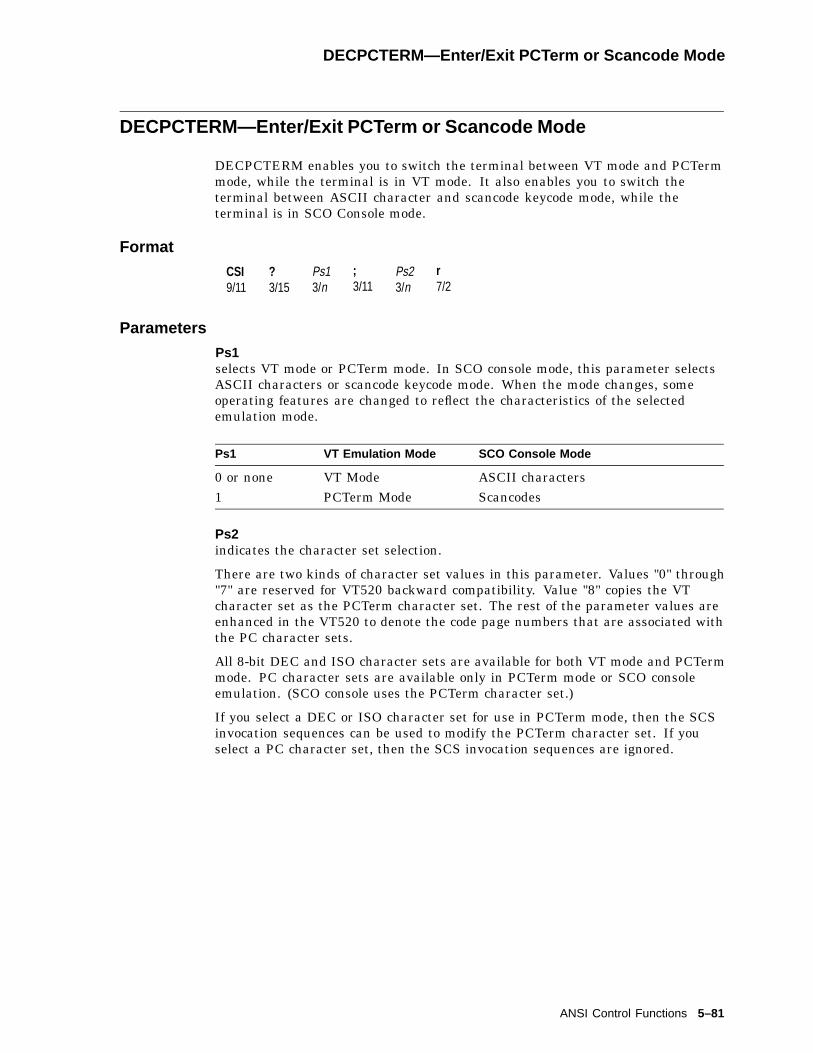
DECPCTERM—Enter/Exit PCTerm or Scancode Mode
DECPCTERM—Enter/Exit PCTerm or Scancode Mode
DECPCTERM enables you to switch the terminal between VT mode and PCTermmode, while the terminal is in VT mode. It also enables you to switch theterminal between ASCII character and scancode keycode mode, while theterminal is in SCO Console mode.
Format
CSI9/11
?3/15
Ps13/n
;3/11
Ps23/n
r7/2
Parameters
Ps1selects VT mode or PCTerm mode. In SCO console mode, this parameter selectsASCII characters or scancode keycode mode. When the mode changes, someoperating features are changed to reflect the characteristics of the selectedemulation mode.
Ps1 VT Emulation Mode SCO Console Mode
0 or none VT Mode ASCII characters1 PCTerm Mode Scancodes
Ps2indicates the character set selection.
There are two kinds of character set values in this parameter. Values "0" through"7" are reserved for VT520 backward compatibility. Value "8" copies the VTcharacter set as the PCTerm character set. The rest of the parameter values areenhanced in the VT520 to denote the code page numbers that are associated withthe PC character sets.
All 8-bit DEC and ISO character sets are available for both VT mode and PCTermmode. PC character sets are available only in PCTerm mode or SCO consoleemulation. (SCO console uses the PCTerm character set.)
If you select a DEC or ISO character set for use in PCTerm mode, then the SCSinvocation sequences can be used to modify the PCTerm character set. If youselect a PC character set, then the SCS invocation sequences are ignored.
ANSI Control Functions 5–81
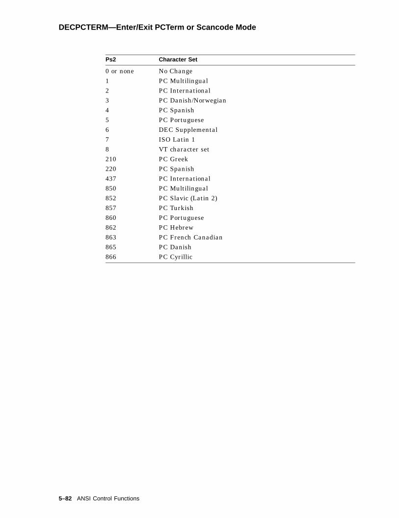
DECPCTERM—Enter/Exit PCTerm or Scancode Mode
Ps2 Character Set
0 or none No Change1 PC Multilingual2 PC International3 PC Danish/Norwegian4 PC Spanish5 PC Portuguese6 DEC Supplemental7 ISO Latin 18 VT character set210 PC Greek220 PC Spanish437 PC International850 PC Multilingual852 PC Slavic (Latin 2)857 PC Turkish860 PC Portuguese862 PC Hebrew863 PC French Canadian865 PC Danish866 PC Cyrillic
5–82 ANSI Control Functions

DECPEX—Print Extent Mode
DECPEX—Print Extent Mode
This control function selects how much data you can print when you use the printpage function.
Default: Scrolling region
Format
CSI9/11
?3/15
13/1
93/9
h6/8
The print function prints the completepage.
CSI9/11
?3/15
13/1
93/9
l6/12
The print function prints the scrollingregion only (data inside the margins).
DECPFF—Print Form Feed Mode
This control function selects whether or not the terminal sends a form feed (FF)character to the printer at the end of a printing function. DECPFF does not affectthe print cursor line function described in the next section.
Default: No form feed
Format
CSI9/11
?3/15
13/1
83/8
h6/8
The terminal sends a form feed (FF) to theprinter at the end of a printing function.
CSI9/11
?3/15
13/1
83/8
l6/12
The terminal sends nothing to the printerat the end of a printing function.
ANSI Control Functions 5–83

DECPFK—Program Function Key
DECPFK—Program Function Key
Allows users to program keys to perform user-preferred functions.
Format
DCS9/0
"2/2
x7/8
D . . . D. . .
ST9/12
Description
This sequence programs one or more keys (and their modifier combinations) fromthe current state to perform user-desired functions. The type of the functionprogrammed must be either:
• a local terminal function
• a user-defined sequence (same as UDK)
This sequence is ignored when the program key function is locked throughDECPKA, DECUDK, or Set-Up.
There are 768 bytes reserved for programmable key operations. This memory isshared by the following four functions:
• Program keys through DECPFK or through Set-Up
• Program keys through DECPAK or through Set-Up
• Copy other key default through DECCKD or Set-Up
• Program user-defined keys through DECUDK
Space is supplied on a first-come, first-serve basis. Once the 768 bytes are used,no more keys may be redefined unless space is made available. Space may bemade available by restoring keys back to their default states. There are fourways to do this:
• Execute a Restore factory defaults from the Set-Up main menu. All theterminal parameters, including the keys, return to their default states.
• Execute a ‘‘Restore factory defaults of all keys and key definitions’’ eitherthrough DECPKA (Program Key Action) or Recall key definitions inSet-Up. This action also releases the 768 bytes.
• Execute a Copy key default to copy a key’s own default either throughDECCKD or in Set-Up to free the space occupied by the destination key.
• Clear UDKs by issuing a clear function in DECUDK.
The free bytes left for key programming can be seen using the Define KeyEditor in Set-Up.
The format of data string D...D is:
Key1/Mod1/Function #/UDS/UDS Direction; Key2/Mod2/Function #/UDS/UDS Direction;........;
• Keyn is the key station number and a slash "/ " is a delimiter.
5–84 ANSI Control Functions

DECPFK—Program Function Key
Refer to Chapter 8 for the key station number map.
• Modn denotes the modifier key that is to be pressed at the same time as thedefined key.
Modn Modifier Key
0 or None Normal1 Normal2 Shift3 Alt4 Alt + Shift5 Control6 Shift + Control7 Alt + Control8 Alt + Control + Shift
• ‘‘Function #’’ represents a number associated with a local function. Forexample, function number "0" is used to make the key or key/modifierinoperative. Function number "100" indicates a user-defined sequence (UDS)and UDS direction is defined following the slash "/ " delimiter. Refer toChapter 8.
• UDS is a user-defined sequence with a maximum length of 255 bytes, whichmust be written in Hex format for DEC/ANSI terminals. Each hex code inthis string represents a value transmitted by the defined key combined withthe modifiers.
UDS in DECPFK is functionally equivalent to the string Stn in theDECUDK control function.
DECUDK is reserved in this terminal for backward compatibility withprevious VT terminals. See DECUDK—User Defined Keys.
• UDS Direction indicates the direction of the UDS transmission.
Direction UDS is sent to the . . .
Remote Host only.Local Terminal screen only.Normal Host and/or the terminal, depending on the setting of the
COMM mode parameter.For full-duplex mode, the key sequence is directed tothe host.For local mode, the sequence is sent to the screenonly.
UDS Direction Direction
0 or None Normal (Default)1 Local2 Remote
ANSI Control Functions 5–85
DECPFK—Program Function Key
Any of the following four methods may be used to define a key to transmit auser-defined sequence (either single byte or multiple bytes):
• Control function DECPFK
• Control function DECPAK
• Control function DECUDK
• In Set-Up, Define key . . .
Once programmed, the key state is not effected by the terminal mode changeslisted below:
• Keyboard mode change, such as switching between Data Processing mode andTypewriter mode
• Character Mode change, such as switching between 7-bit character and 8-bitcharacter
• Keyboard Layout change, such as switching between PC layout and VT layout
• Keyboard Style change, such as switching between PC-style and VT-style
• Terminal Mode change, such as switching between VT100 and VT500
Redefining Keys on the Numeric Keypad
Using Define key... to redefine keys on the numeric keypad will affect onlythe Num Lock off state of these keys. When Num Lock is on, these keys willalways send their factory default ASCII numerals and characters. The Num Lockbehavior of these keys cannot be reprogrammed.
Scenario: Imagine the keyboard having two numeric keypads: one for Num LockOff, and the other for Num Lock On. Only the Num Lock Off keypad can bereprogrammed. The Num Lock On keypad retains the factory defaults.
This function works in all the ANSI VT modes except VT52 mode.
5–86 ANSI Control Functions
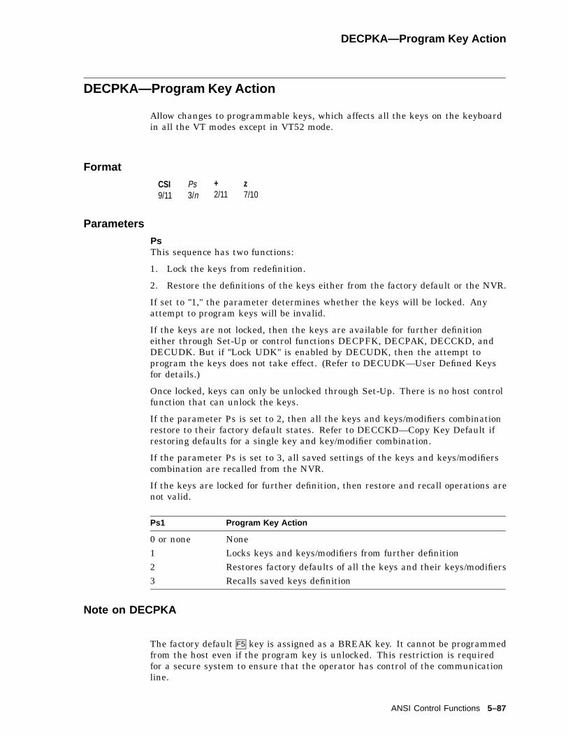
DECPKA—Program Key Action
DECPKA—Program Key Action
Allow changes to programmable keys, which affects all the keys on the keyboardin all the VT modes except in VT52 mode.
Format
CSI9/11
Ps3/n
+2/11
z7/10
Parameters
PsThis sequence has two functions:
1. Lock the keys from redefinition.
2. Restore the definitions of the keys either from the factory default or the NVR.
If set to "1," the parameter determines whether the keys will be locked. Anyattempt to program keys will be invalid.
If the keys are not locked, then the keys are available for further definitioneither through Set-Up or control functions DECPFK, DECPAK, DECCKD, andDECUDK. But if "Lock UDK" is enabled by DECUDK, then the attempt toprogram the keys does not take effect. (Refer to DECUDK—User Defined Keysfor details.)
Once locked, keys can only be unlocked through Set-Up. There is no host controlfunction that can unlock the keys.
If the parameter Ps is set to 2, then all the keys and keys/modifiers combinationrestore to their factory default states. Refer to DECCKD—Copy Key Default ifrestoring defaults for a single key and key/modifier combination.
If the parameter Ps is set to 3, all saved settings of the keys and keys/modifierscombination are recalled from the NVR.
If the keys are locked for further definition, then restore and recall operations arenot valid.
Ps1 Program Key Action
0 or none None1 Locks keys and keys/modifiers from further definition2 Restores factory defaults of all the keys and their keys/modifiers3 Recalls saved keys definition
Note on DECPKA
The factory default F5 key is assigned as a BREAK key. It cannot be programmedfrom the host even if the program key is unlocked. This restriction is requiredfor a secure system to ensure that the operator has control of the communicationline.
ANSI Control Functions 5–87

DECPKFMR—Program Key Free Memory Report
DECPKFMR—Program Key Free Memory Report
Report the free memory space for program key operations.
Format
CSI9/11
Ps13/n
;3/11
Ps23/n
+2/11
y7/9
Parameters
Ps1denotes the total memory space in bytes that is reserved for the programmablekeys. The total memory available is 768 bytes, hence the Ps1 value is "768."
Ps2denotes the memory space that is available at the time DECRQPKFM is received,depending on the number of bytes left in decimal format. An "0" indicates that nomemory is left for any key programming operation; in which case, any attempt toprogram the keys will fail.
Description
The VT520 reports this sequence upon receiving DECRQPKFM from the host.
Note on DECPKFMR
The VT520 firmware data structure uses some memory to program the keydefinitions; therefore, the free bytes reported by Ps2 do not represent the exactbytes available for users. A program to enter a definition that has the same bytecount as reported by Ps2 may not be valid.
5–88 ANSI Control Functions

DECPS—Play Sound
DECPS—Play Sound
Controls the sound frequency or notes (one at a time).
Format
CSI9/11
Pvolume; Pduration; Pnote,2/12
~7/14
Parameters
PvolumeSound volume
0 = off1...3 (low)4...7 (high)
PdurationDuration of note in 1/32 of a second
PnoteNote
Pnote Note ~F (Hz) Pnote Note ~F (Hz)1 C5 14 C#6 10472 C#5 15 D63 D5 16 D#64 D#5(Eb) 632 17 E65 E5 18 F66 F5 19 F#67 F#5 20 G68 G5 21 G#69 G#5 847 22 A610 A5 23 A#611 A#5 944 24 B612 B5 25 C713 C6
Description
The terminal’s sound buffer can store 16 notes of specified volume and duration.Additional sound controls are held in the communications input buffer invokingreceive data flow control as needed.
There is no TSI report for sounds played.
ANSI Control Functions 5–89
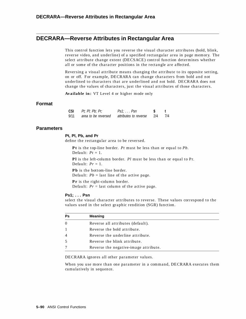
DECRARA—Reverse Attributes in Rectangular Area
DECRARA—Reverse Attributes in Rectangular Area
This control function lets you reverse the visual character attributes (bold, blink,reverse video, and underline) of a specified rectangular area in page memory. Theselect attribute change extent (DECSACE) control function determines whetherall or some of the character positions in the rectangle are affected.
Reversing a visual attribute means changing the attribute to its opposite setting,on or off. For example, DECRARA can change characters from bold and notunderlined to characters that are underlined and not bold. DECRARA does notchange the values of characters, just the visual attributes of those characters.
Available in: VT Level 4 or higher mode only
Format
CSI9/11
Pt; Pl; Pb; Pr;area to be reversed
Ps1; . . . Psnattributes to reverse
$2/4
t7/4
Parameters
Pt, Pl, Pb, and Prdefine the rectangular area to be reversed.
Pt is the top-line border. Pt must be less than or equal to Pb.Default: Pt = 1.
Pl is the left-column border. Pl must be less than or equal to Pr.Default: Pr = 1.
Pb is the bottom-line border.Default: Pb = last line of the active page.
Pr is the right-column border.Default: Pr = last column of the active page.
Ps1; . . . Psnselect the visual character attributes to reverse. These values correspond to thevalues used in the select graphic rendition (SGR) function.
Ps Meaning
0 Reverse all attributes (default).1 Reverse the bold attribute.4 Reverse the underline attribute.5 Reverse the blink attribute.7 Reverse the negative-image attribute.
DECRARA ignores all other parameter values.
When you use more than one parameter in a command, DECRARA executes themcumulatively in sequence.
5–90 ANSI Control Functions

DECRARA—Reverse Attributes in Rectangular Area
Examples
The following sequence reverses the blink and underscore attributes of thecomplete screen:
CSI ; ; ; ; 0; 4; 5; $ t
The following sequence reverses all attributes except the blink attribute, fromposition line 10, column 2 to position line 14, column 45 on the current page:
CSI 10; 2; 14; 45; 1; 4; 7 $ t
Notes on DECRARA
• The coordinates of the rectangular area are affected by the setting of originmode (DECOM).
• DECRARA is not affected by the page margins.
• If the value of Pt, Pl, Pb, or Pr exceeds the width or height of the active page,then the value is treated as the width or height of that page.
• DECRARA does not change the active cursor position.
• DECRARA does not change the current rendition set by the select graphicrendition (SGR) function.
• The exact character positions affected by DECRARA depend on the currentsetting of the select attribute change extent (DECSACE) function.
ANSI Control Functions 5–91
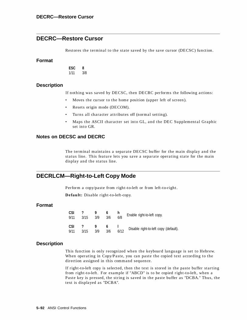
DECRC—Restore Cursor
DECRC—Restore Cursor
Restores the terminal to the state saved by the save cursor (DECSC) function.
Format
ESC1/11
83/8
Description
If nothing was saved by DECSC, then DECRC performs the following actions:
• Moves the cursor to the home position (upper left of screen).
• Resets origin mode (DECOM).
• Turns all character attributes off (normal setting).
• Maps the ASCII character set into GL, and the DEC Supplemental Graphicset into GR.
Notes on DECSC and DECRC
The terminal maintains a separate DECSC buffer for the main display and thestatus line. This feature lets you save a separate operating state for the maindisplay and the status line.
DECRLCM—Right-to-Left Copy Mode
Perform a copy/paste from right-to-left or from left-to-right.
Default: Disable right-to-left-copy.
Format
CSI9/11
?3/15
93/9
63/6
h6/8
Enable right-to-left copy.
CSI9/11
?3/15
93/9
63/6
l6/12
Disable right-to-left copy (default).
Description
This function is only recognized when the keyboard language is set to Hebrew.When operating in Copy/Paste, you can paste the copied text according to thedirection assigned in this command sequence.
If right-to-left copy is selected, then the text is stored in the paste buffer startingfrom right-to-left. For example if "ABCD" is to be copied right-to-left, when aPaste key is pressed, the string is saved in the paste buffer as "DCBA." Thus, thetext is displayed as "DCBA".
5–92 ANSI Control Functions
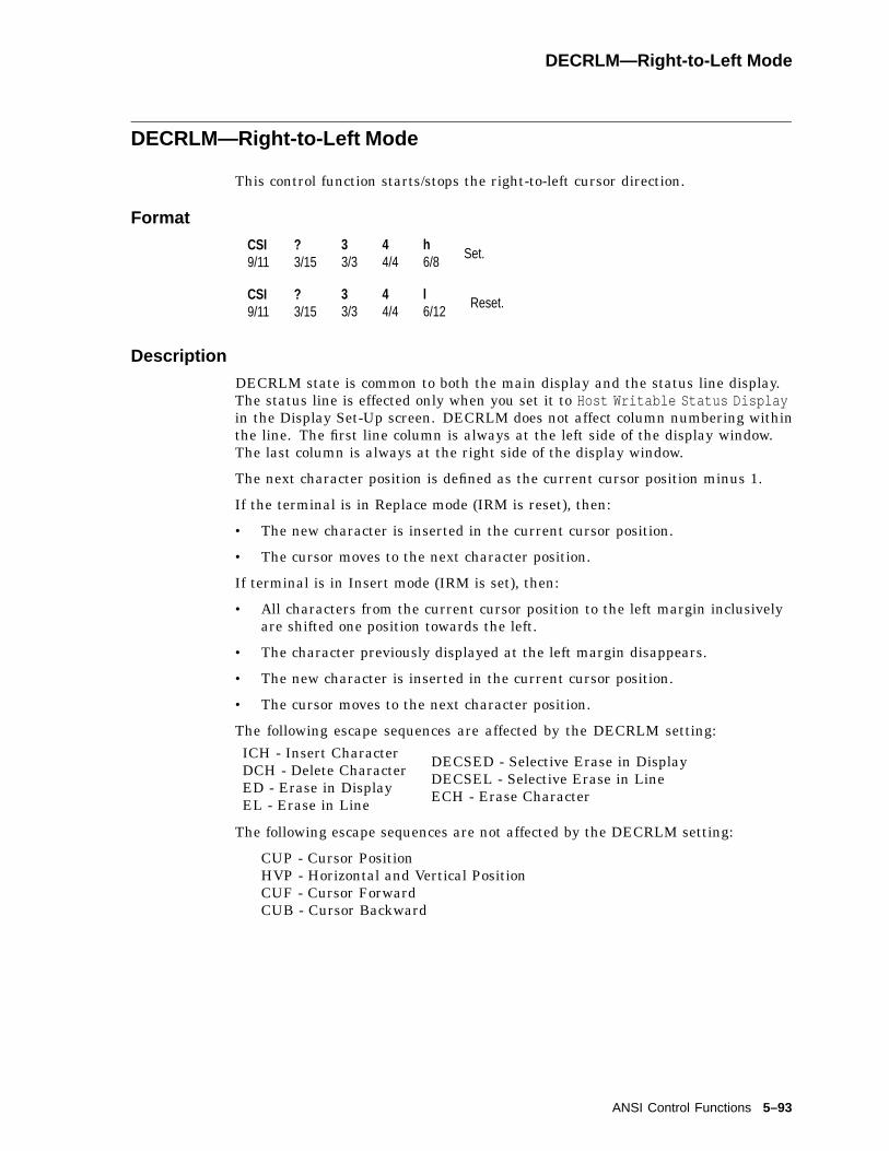
DECRLM—Right-to-Left Mode
DECRLM—Right-to-Left Mode
This control function starts/stops the right-to-left cursor direction.
Format
CSI9/11
?3/15
33/3
44/4
h6/8
Set.
CSI9/11
?3/15
33/3
44/4
l6/12
Reset.
Description
DECRLM state is common to both the main display and the status line display.The status line is effected only when you set it to Host Writable Status Displayin the Display Set-Up screen. DECRLM does not affect column numbering withinthe line. The first line column is always at the left side of the display window.The last column is always at the right side of the display window.
The next character position is defined as the current cursor position minus 1.
If the terminal is in Replace mode (IRM is reset), then:
• The new character is inserted in the current cursor position.
• The cursor moves to the next character position.
If terminal is in Insert mode (IRM is set), then:
• All characters from the current cursor position to the left margin inclusivelyare shifted one position towards the left.
• The character previously displayed at the left margin disappears.
• The new character is inserted in the current cursor position.
• The cursor moves to the next character position.
The following escape sequences are affected by the DECRLM setting:
ICH - Insert CharacterDCH - Delete CharacterED - Erase in DisplayEL - Erase in Line
DECSED - Selective Erase in DisplayDECSEL - Selective Erase in LineECH - Erase Character
The following escape sequences are not affected by the DECRLM setting:
CUP - Cursor PositionHVP - Horizontal and Vertical PositionCUF - Cursor ForwardCUB - Cursor Backward
ANSI Control Functions 5–93
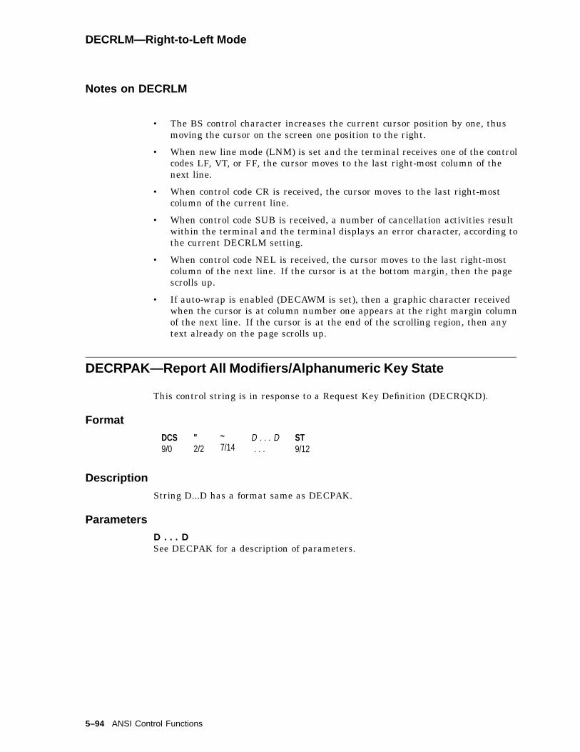
DECRLM—Right-to-Left Mode
Notes on DECRLM
• The BS control character increases the current cursor position by one, thusmoving the cursor on the screen one position to the right.
• When new line mode (LNM) is set and the terminal receives one of the controlcodes LF, VT, or FF, the cursor moves to the last right-most column of thenext line.
• When control code CR is received, the cursor moves to the last right-mostcolumn of the current line.
• When control code SUB is received, a number of cancellation activities resultwithin the terminal and the terminal displays an error character, according tothe current DECRLM setting.
• When control code NEL is received, the cursor moves to the last right-mostcolumn of the next line. If the cursor is at the bottom margin, then the pagescrolls up.
• If auto-wrap is enabled (DECAWM is set), then a graphic character receivedwhen the cursor is at column number one appears at the right margin columnof the next line. If the cursor is at the end of the scrolling region, then anytext already on the page scrolls up.
DECRPAK—Report All Modifiers/Alphanumeric Key State
This control string is in response to a Request Key Definition (DECRQKD).
Format
DCS9/0
"2/2
~7/14
D . . . D. . .
ST9/12
Description
String D...D has a format same as DECPAK.
Parameters
D . . . DSee DECPAK for a description of parameters.
5–94 ANSI Control Functions

DECRPDE—Report Displayed Extent
DECRPDE—Report Displayed Extent
The terminal sends this control function in response to a request displayed extent(DECRQDE) sequence. DECRPDE indicates how much of the current page isdisplayed on the screen.
DECRPDE indicates how much of the screen has to display the current page.
Format
CSI9/11
Ph3/n
;3/11
Pw3/n
;3/11
Pml3/n
;3/11
Pmt3/n
;3/11
Pmp3/n
;3/11
"2/2
w7/7
Parameters
Phis the number of lines of the current page displayed excluding the status line.
Pwis the number of columns of the current page displayed.
Pmlis the column number displayed in the left-most column.
Pmtis the line number displayed in the top line.
Pmpis the page number displayed.
ANSI Control Functions 5–95
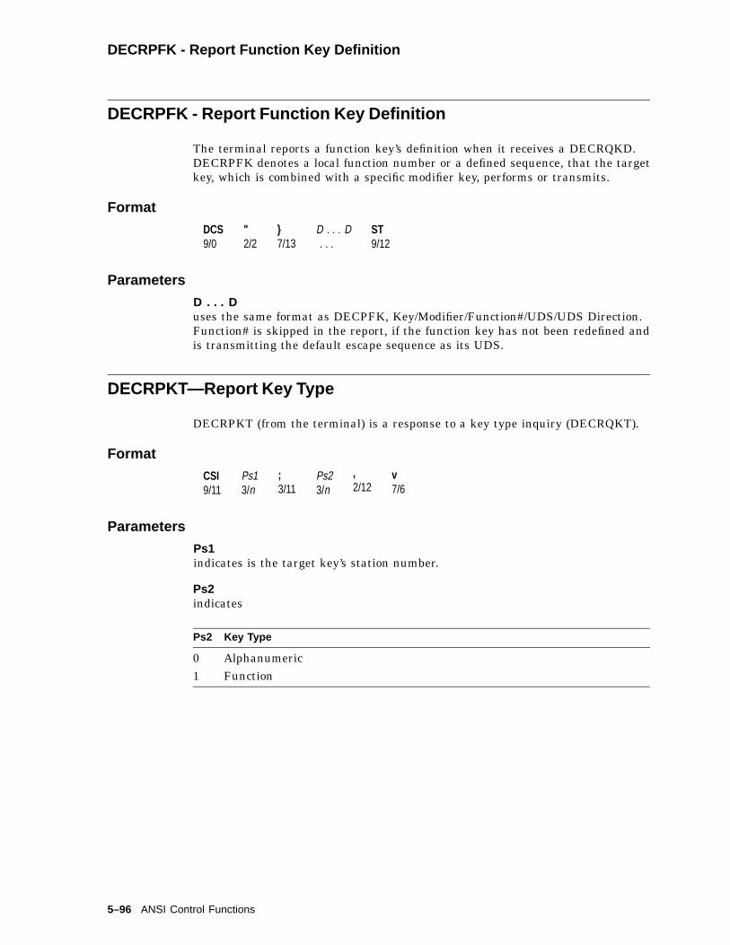
DECRPFK - Report Function Key Definition
DECRPFK - Report Function Key Definition
The terminal reports a function key’s definition when it receives a DECRQKD.DECRPFK denotes a local function number or a defined sequence, that the targetkey, which is combined with a specific modifier key, performs or transmits.
Format
DCS9/0
"2/2
}7/13
D . . . D. . .
ST9/12
Parameters
D . . . Duses the same format as DECPFK, Key/Modifier/Function#/UDS/UDS Direction.Function# is skipped in the report, if the function key has not been redefined andis transmitting the default escape sequence as its UDS.
DECRPKT—Report Key Type
DECRPKT (from the terminal) is a response to a key type inquiry (DECRQKT).
Format
CSI9/11
Ps13/n
;3/11
Ps23/n
,2/12
v7/6
Parameters
Ps1indicates is the target key’s station number.
Ps2indicates
Ps2 Key Type
0 Alphanumeric1 Function
5–96 ANSI Control Functions

DECRPL—Review Previous Lines Mode
DECRPL—Review Previous Lines Mode
Allows user to view lines previously scrolled off the top of the page.
Default: Review previous lines disabled
Format
CSI9/11
?3/15
13/1
13/1
23/2
h6/8
Set: enables review previous lines
CSI9/11
?3/15
13/1
13/1
23/2
l6/12
Reset: disables review previous lines
Description
This command rearranges page memory into a single page and a scroll backbuffer (transcript). Refer to Set-Up chapter for details.
DECRPL can be reported using DECRQM and DECRPM.
ANSI Control Functions 5–97
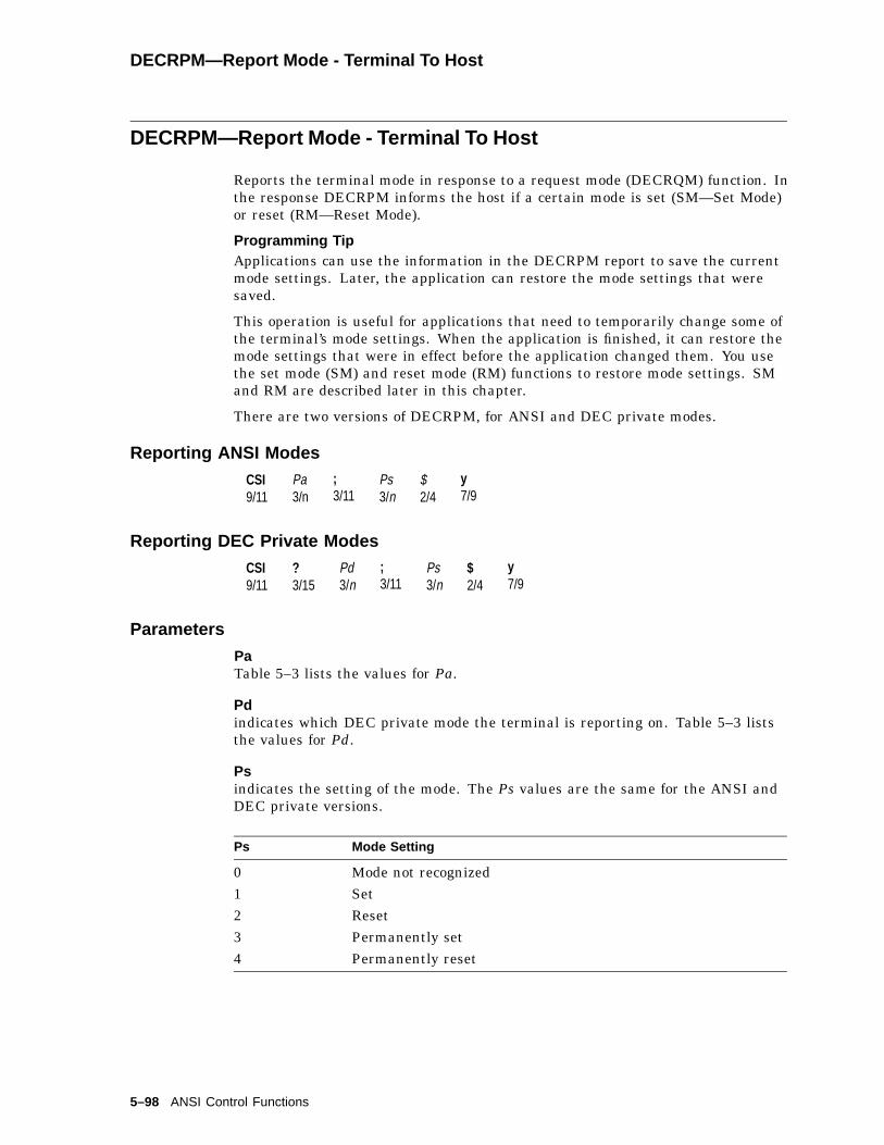
DECRPM—Report Mode - Terminal To Host
DECRPM—Report Mode - Terminal To Host
Reports the terminal mode in response to a request mode (DECRQM) function. Inthe response DECRPM informs the host if a certain mode is set (SM—Set Mode)or reset (RM—Reset Mode).
Programming TipApplications can use the information in the DECRPM report to save the currentmode settings. Later, the application can restore the mode settings that weresaved.
This operation is useful for applications that need to temporarily change some ofthe terminal’s mode settings. When the application is finished, it can restore themode settings that were in effect before the application changed them. You usethe set mode (SM) and reset mode (RM) functions to restore mode settings. SMand RM are described later in this chapter.
There are two versions of DECRPM, for ANSI and DEC private modes.
Reporting ANSI Modes
CSI9/11
Pa3/n
;3/11
Ps3/n
$2/4
y7/9
Reporting DEC Private Modes
CSI9/11
?3/15
Pd3/n
;3/11
Ps3/n
$2/4
y7/9
Parameters
PaTable 5–3 lists the values for Pa.
Pdindicates which DEC private mode the terminal is reporting on. Table 5–3 liststhe values for Pd.
Psindicates the setting of the mode. The Ps values are the same for the ANSI andDEC private versions.
Ps Mode Setting
0 Mode not recognized1 Set2 Reset3 Permanently set4 Permanently reset
5–98 ANSI Control Functions
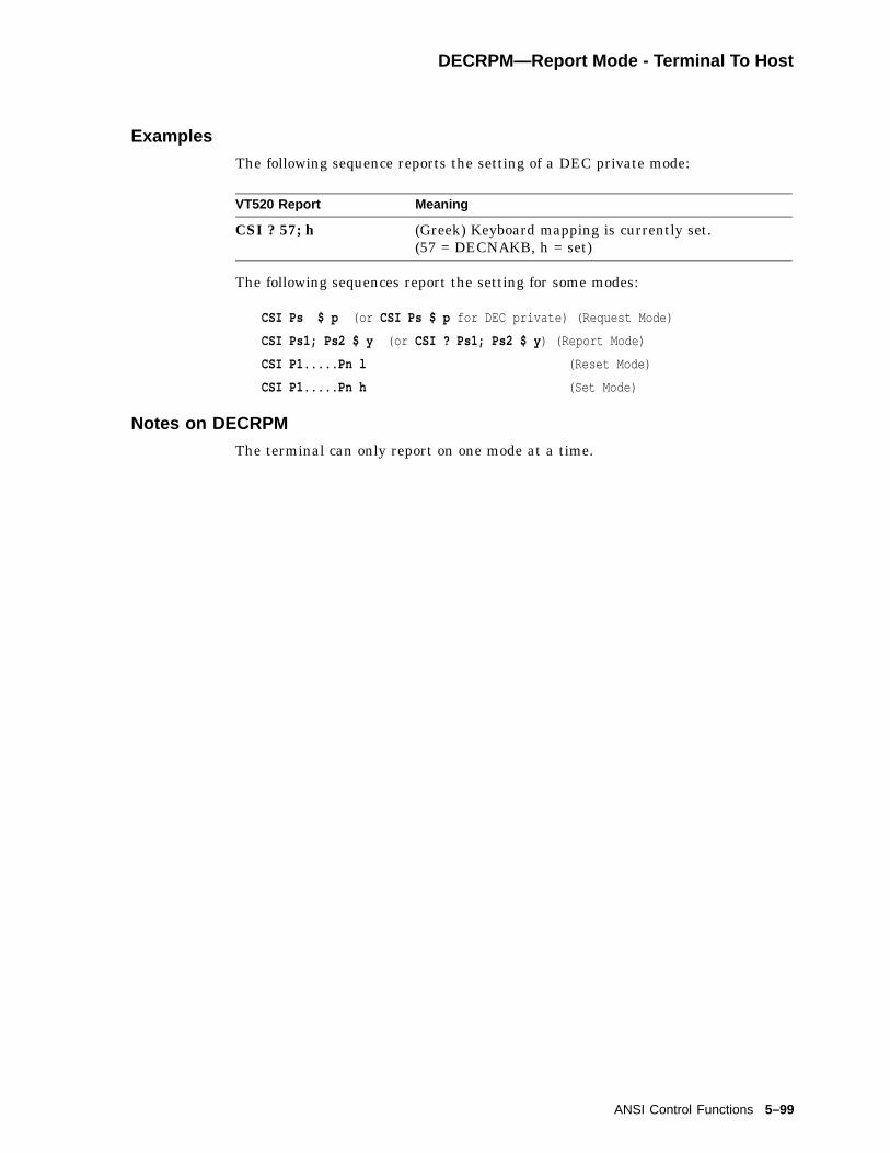
DECRPM—Report Mode - Terminal To Host
Examples
The following sequence reports the setting of a DEC private mode:
VT520 Report Meaning
CSI ? 57; h (Greek) Keyboard mapping is currently set.(57 = DECNAKB, h = set)
The following sequences report the setting for some modes:
CSI Ps $ p (or CSI Ps $ p for DEC private) (Request Mode)
CSI Ps1; Ps2 $ y (or CSI ? Ps1; Ps2 $ y ) (Report Mode)
CSI P1.....Pn l (Reset Mode)
CSI P1.....Pn h (Set Mode)
Notes on DECRPM
The terminal can only report on one mode at a time.
ANSI Control Functions 5–99

DECRPM—Report Mode - Terminal To Host
Description
DECRQM, DECRPM, SM, and RM support all the mode settings as follows:
Table 5–3 Settings Supported by DECRQM, DECRPM, RM, and SM
ANSI-Specified Mode DEC-Private ModePa Mnemonic Pd Mnemonic
1 GATM� ?1 DECCKM2 KAM ?2 DECANM†3 CRM ?3 DECOLM4 IRM ?4 DECSCLM5 SRTM� ?5 DECSCNM
?6 DECOM7 VEM� ?7 DECAWM
?8 DECARM10 HEM� – –11 PUM� – –12 SRM13 FEAM� – –14 FETM� – –15 MATM� – –16 TTM� – –17 SATM� – –18 TSM� ?18 DECPFF19 EBM� ?19 DECPEX20 LNM – –– – ?25 DECTCEM– – ?34 DECRLM– – ?35 DECHEBM– – ?36 DECHEM– – ?42 DECNRCM– – ?57 DECNAKB– – ?60 DECHCCM *– – ?61 DECVCCM– – ?64 DECPCCM– – ?66 DECNKM– – ?67 DECBKM– – ?68 DECKBUM– – ?69 DECLRMM (DECVSSM)– – ?73 DECXRLMM
�This mode is always reset in the terminal and cannot be changed.†When the terminal is set to VT52 mode, DECRQM provides no report.
(continued on next page)
5–100 ANSI Control Functions

DECRPM—Report Mode - Terminal To Host
Table 5–3 (Cont.) Settings Supported by DECRQM, DECRPM, RM, and SM
ANSI-Specified Mode DEC-Private ModePa Mnemonic Pd Mnemonic
– – ?95 DECNCSM– – ?96 DECRLCM– – ?97 DECCRTSM– – ?98 DECARSM– – ?99 DECMCM– – ?100 DECAAM– – ?101 DECCANSM– – ?102 DECNULM– – ?103 DECHDPXM– – ?104 DECESKM– – ?106 DECOSCNM– – ?111 DECFWM– – ?112 DECRPL– – ?113 DECHWUM– – ?114 DECATCUM– – ?115 DECATCMB– – ?116 DECBSM– – ?117 DECECM
ANSI Control Functions 5–101

DECRPSS—Report Selection or Setting
DECRPSS—Report Selection or Setting
The terminal sends the host this sequence in response to a request selection orsetting (DECRQSS) sequence. The terminal sends DECRPSS to report the settingof a particular control function.
Programming TipApplications can use the information in the DECRPSS report to save the currentselections or settings of some control functions. Later, the application can restorethe control functions to their saved state.
This operation is useful for applications that need to temporarily change thesettings of some of the terminal’s control functions. When the application isfinished, it can restore the control functions to their previous state.
Format
DCS9/0
Ps3/n
$2/4
r7/2
D . . . D. . .
ST9/12
Parameters
Psindicates whether or not the request from the host is valid.
Ps Host Request
0 Host’s request is valid.1 Host’s request is invalid.
D . . . Dindicates the current setting of a valid control function that the host asked about.D...D consists of all the characters in the control function, except the CSI (9/11) orESC [ (1/11, 5/11) introducer characters.
Examples
The host requests the setting of the select graphic rendition (SGR) function.If the current graphic rendition is underline, blinking, and reverse, then theterminal responds with the following DECRPSS sequence:
DCS 0 $ r 0 ; 4 ; 5 ; 7 m ST
0; 4 ; 5 ; 7 m are all the characters in the SGR sequence, except CSI.
The host requests the setting of the set top and bottom margin function(DECSTBM). If the current top and bottom margins are set to include thecomplete screen area (24 lines/screen), then the terminal responds with thefollowing DECRPSS sequence:
DCS 0 $ r 1 ; 24 r ST
1 ; 24 r are all the characters in the DECSTBM sequence, except CSI.
5–102 ANSI Control Functions
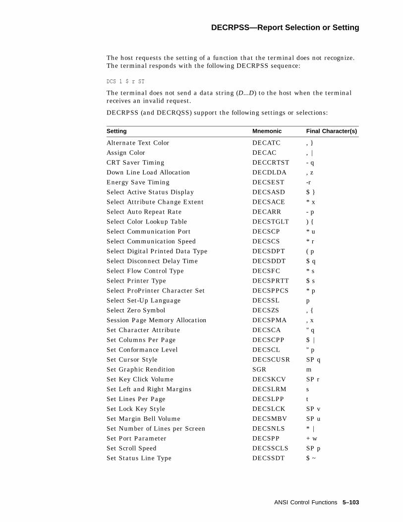
DECRPSS—Report Selection or Setting
The host requests the setting of a function that the terminal does not recognize.The terminal responds with the following DECRPSS sequence:
DCS 1 $ r ST
The terminal does not send a data string (D...D) to the host when the terminalreceives an invalid request.
DECRPSS (and DECRQSS) support the following settings or selections:
Setting Mnemonic Final Character(s)
Alternate Text Color DECATC , }Assign Color DECAC , |CRT Saver Timing DECCRTST - qDown Line Load Allocation DECDLDA , zEnergy Save Timing DECSEST -rSelect Active Status Display DECSASD $ }Select Attribute Change Extent DECSACE * xSelect Auto Repeat Rate DECARR - pSelect Color Lookup Table DECSTGLT ) {Select Communication Port DECSCP * uSelect Communication Speed DECSCS * rSelect Digital Printed Data Type DECSDPT ( pSelect Disconnect Delay Time DECSDDT $ qSelect Flow Control Type DECSFC * sSelect Printer Type DECSPRTT $ sSelect ProPrinter Character Set DECSPPCS * pSelect Set-Up Language DECSSL pSelect Zero Symbol DECSZS , {Session Page Memory Allocation DECSPMA , xSet Character Attribute DECSCA " qSet Columns Per Page DECSCPP $ |Set Conformance Level DECSCL " pSet Cursor Style DECSCUSR SP qSet Graphic Rendition SGR mSet Key Click Volume DECSKCV SP rSet Left and Right Margins DECSLRM sSet Lines Per Page DECSLPP tSet Lock Key Style DECSLCK SP vSet Margin Bell Volume DECSMBV SP uSet Number of Lines per Screen DECSNLS * |Set Port Parameter DECSPP + wSet Scroll Speed DECSSCLS SP pSet Status Line Type DECSSDT $ ~
ANSI Control Functions 5–103
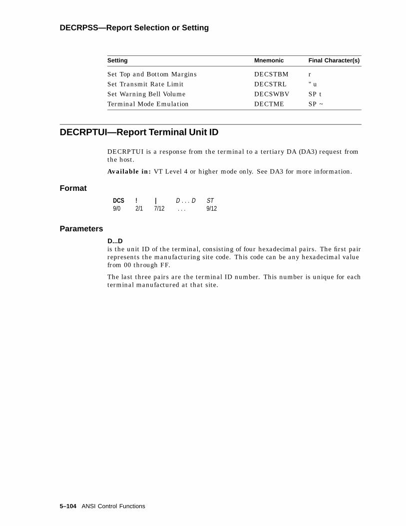
DECRPSS—Report Selection or Setting
Setting Mnemonic Final Character(s)
Set Top and Bottom Margins DECSTBM rSet Transmit Rate Limit DECSTRL " uSet Warning Bell Volume DECSWBV SP tTerminal Mode Emulation DECTME SP ~
DECRPTUI—Report Terminal Unit ID
DECRPTUI is a response from the terminal to a tertiary DA (DA3) request fromthe host.
Available in: VT Level 4 or higher mode only. See DA3 for more information.
Format
DCS9/0
!2/1
|7/12
D . . . D. . .
ST9/12
Parameters
D...Dis the unit ID of the terminal, consisting of four hexadecimal pairs. The first pairrepresents the manufacturing site code. This code can be any hexadecimal valuefrom 00 through FF.
The last three pairs are the terminal ID number. This number is unique for eachterminal manufactured at that site.
5–104 ANSI Control Functions
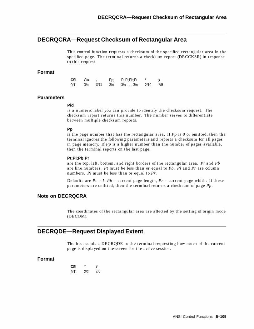
DECRQCRA—Request Checksum of Rectangular Area
DECRQCRA—Request Checksum of Rectangular Area
This control function requests a checksum of the specified rectangular area in thespecified page. The terminal returns a checksum report (DECCKSR) in responseto this request.
Format
CSI9/11
Pid3/n
;3/11
Pp;3/n
Pt;Pl;Pb;Pr3/n . . . 3/n
*2/10
y7/9
Parameters
Pidis a numeric label you can provide to identify the checksum request. Thechecksum report returns this number. The number serves to differentiatebetween multiple checksum reports.
Ppis the page number that has the rectangular area. If Pp is 0 or omitted, then theterminal ignores the following parameters and reports a checksum for all pagesin page memory. If Pp is a higher number than the number of pages available,then the terminal reports on the last page.
Pt;Pl;Pb;Prare the top, left, bottom, and right borders of the rectangular area. Pt and Pbare line numbers. Pt must be less than or equal to Pb. Pl and Pr are columnnumbers. Pl must be less than or equal to Pr.
Defaults are Pt = 1, Pb = current page length, Pr = current page width. If theseparameters are omitted, then the terminal returns a checksum of page Pp.
Note on DECRQCRA
The coordinates of the rectangular area are affected by the setting of origin mode(DECOM).
DECRQDE—Request Displayed Extent
The host sends a DECRQDE to the terminal requesting how much of the currentpage is displayed on the screen for the active session.
Format
CSI9/11
"2/2
v7/6
ANSI Control Functions 5–105

DECRQKD—Request Key Definition
DECRQKD—Request Key Definition
DECRQKD allows you to inquire about the terminal’s definition of:
• A function key or a function key combined with a single modifier key.
• An alphanumeric key combined with all of its available modifier keys.
The terminal reports the function key definition with DECRPFK, and thealphanumeric key definition with DECRPAK.
Format
CSI9/11
Ps13/n
;3/11
Ps23/n
,2/12
w7/7
Parameters
Ps1indicates is the target key’s station number. When inquiring for an alphanumerickey definition, Ps2 is ignored by the terminal. DECRPAK always reports ahexadecimal string in which each code represents a value transmitted by pressinga combination of the target key and a modifier key. See DECRPAK.
psWhen inquiring for a function key definition, Ps2 represents:
Ps2 Description
0, 1 or none Normal2 Shift3 Alt4 Alt + Shift5 Control6 Shift + Control7 Alt + Control8 Alt + Control + Shift
If you enter an invalid key/modifier, the entire sequence is ignored .
5–106 ANSI Control Functions

DECRQKT—Request Key Type
DECRQKT—Request Key Type
The host issues a DECRQKT to the terminal for the key definition of a functionor alphanumeric key. Upon receiving the request, the terminal reports usingDECRPKT.
Format
CSI9/11
Ps3/n
,2/12
u7/5
Parameters
Psis a decimal number representing the target key’s station number.
ANSI Control Functions 5–107

DECRQM—Request Mode - Host To Terminal
DECRQM—Request Mode - Host To Terminal
The host sends this control function to find out if a particular mode is set or reset.The terminal responds with a report mode function (DECRPM—Report Mode -Terminal To Host).
DECRQM functions in ANSI and DEC private modes.
Requesting ANSI Modes
CSI9/11
Pa3/n
$2/4
p7/0
Requesting DEC Private Modes
CSI9/11
?3/15
Pd3/n
$2/4
p7/0
Parameters
Paindicates the ANSI mode that the host is asking about. Table 5–4 lists the valuesfor Pa.
Pdindicates the DEC private mode the host is asking about. Table 5–5 lists thevalues for Pd.
Examples
The following sequences request the setting of some ANSI modes:
Host Meaning
CSI 2 $ p What is the current state of keyboard action mode (KAM)?(KAM = 2)
CSI 4 $ p What is the current state of insert/replace mode (IRM)?(IRM = 4)
The following sequences request the setting of some DEC private modes:
Host Meaning
CSI ? 36 $ p What is the current state of Hebrew encoding mode(DECHEM)? (DECHEM = 36)
CSI ? 6 $ p What is the current state of origin mode (DECOM)?(DECOM = 6)
5–108 ANSI Control Functions
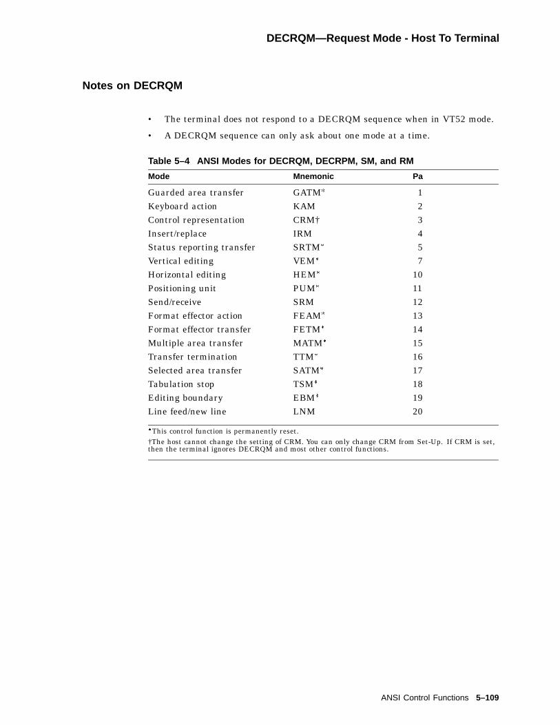
DECRQM—Request Mode - Host To Terminal
Notes on DECRQM
• The terminal does not respond to a DECRQM sequence when in VT52 mode.
• A DECRQM sequence can only ask about one mode at a time.
Table 5–4 ANSI Modes for DECRQM, DECRPM, SM, and RM
Mode Mnemonic Pa
Guarded area transfer GATM� 1Keyboard action KAM 2Control representation CRM† 3Insert/replace IRM 4Status reporting transfer SRTM� 5Vertical editing VEM� 7Horizontal editing HEM� 10Positioning unit PUM� 11Send/receive SRM 12Format effector action FEAM� 13Format effector transfer FETM� 14Multiple area transfer MATM� 15Transfer termination TTM� 16Selected area transfer SATM� 17Tabulation stop TSM� 18Editing boundary EBM� 19Line feed/new line LNM 20
�This control function is permanently reset.†The host cannot change the setting of CRM. You can only change CRM from Set-Up. If CRM is set,then the terminal ignores DECRQM and most other control functions.
ANSI Control Functions 5–109

DECRQM—Request Mode - Host To Terminal
Table 5–5 DEC Private Modes for DECRQM, DECRPM, SM, and RM
Mode Mnemonic Pd
Cursor keys DECCKM 1ANSI DECANM 2Column DECCOLM 3Scrolling DECSCLM 4Screen DECSCNM 5Origin DECOM 6Autowrap DECAWM 7Autorepeat DECARM 8Print form feed DECPFF 18Printer extent DECPEX 19Text cursor enable DECTCEM 25Cursor direction, right to left DECRLM 34Hebrew keyboard mapping DECHEBM 35Hebrew encoding mode DECHEM 36National replacement character set DECNRCM 42Greek keyboard mapping DECNAKB 57Horizontal cursor coupling DECHCCM 60Vertical cursor coupling DECVCCM 61Page cursor coupling DECPCCM 64Numeric keypad DECNKM 66Backarrow key DECBKM 67Keyboard usage DECKBUM 68Vertical split screen DECVSSM
/DECLRMM69
Transmit rate limiting DECXRLM 73Key position mode DECNCSM 95Key position mode DECRLCM 96Key position mode DECCRTSM 97Key position mode DECARSM 98Key position mode DECMCM 99Key position mode DECAAM 100Key position mode DECCANSM 101Key position mode DECNULM 102Key position mode DECHDPXM 103Key position mode DECESKM 104Key position mode DECOSCNM 106
5–110 ANSI Control Functions
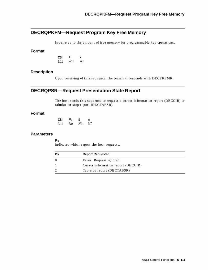
DECRQPKFM—Request Program Key Free Memory
DECRQPKFM—Request Program Key Free Memory
Inquire as to the amount of free memory for programmable key operations.
Format
CSI9/11
+2/11
x7/8
Description
Upon receiving of this sequence, the terminal responds with DECPKFMR.
DECRQPSR—Request Presentation State Report
The host sends this sequence to request a cursor information report (DECCIR) ortabulation stop report (DECTABSR).
Format
CSI9/11
Ps3/n
$2/4
w7/7
Parameters
Psindicates which report the host requests.
Ps Report Requested
0 Error. Request ignored1 Cursor information report (DECCIR)2 Tab stop report (DECTABSR)
ANSI Control Functions 5–111
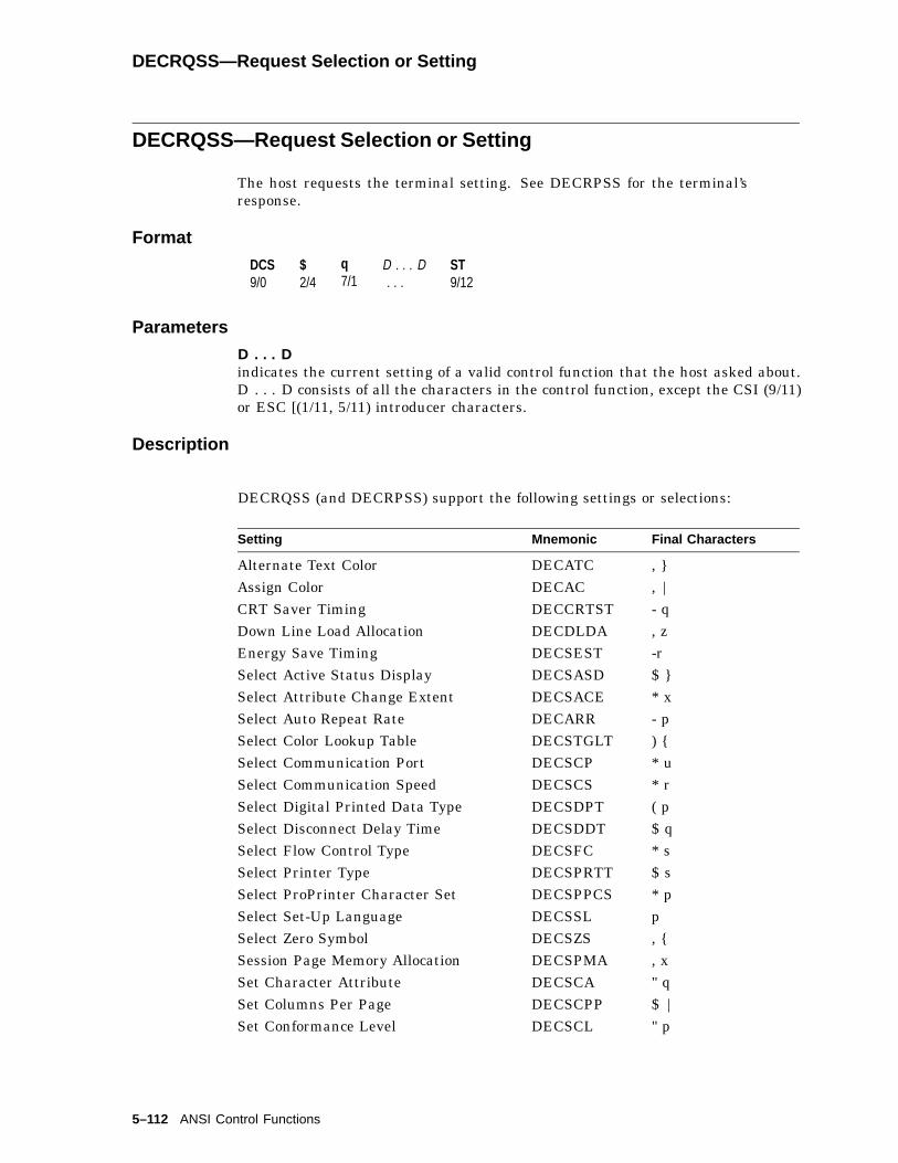
DECRQSS—Request Selection or Setting
DECRQSS—Request Selection or Setting
The host requests the terminal setting. See DECRPSS for the terminal’sresponse.
Format
DCS9/0
$2/4
q7/1
D . . . D. . .
ST9/12
Parameters
D . . . Dindicates the current setting of a valid control function that the host asked about.D . . . D consists of all the characters in the control function, except the CSI (9/11)or ESC [(1/11, 5/11) introducer characters.
Description
DECRQSS (and DECRPSS) support the following settings or selections:
Setting Mnemonic Final Characters
Alternate Text Color DECATC , }Assign Color DECAC , |CRT Saver Timing DECCRTST - qDown Line Load Allocation DECDLDA , zEnergy Save Timing DECSEST -rSelect Active Status Display DECSASD $ }Select Attribute Change Extent DECSACE * xSelect Auto Repeat Rate DECARR - pSelect Color Lookup Table DECSTGLT ) {Select Communication Port DECSCP * uSelect Communication Speed DECSCS * rSelect Digital Printed Data Type DECSDPT ( pSelect Disconnect Delay Time DECSDDT $ qSelect Flow Control Type DECSFC * sSelect Printer Type DECSPRTT $ sSelect ProPrinter Character Set DECSPPCS * pSelect Set-Up Language DECSSL pSelect Zero Symbol DECSZS , {Session Page Memory Allocation DECSPMA , xSet Character Attribute DECSCA " qSet Columns Per Page DECSCPP $ |Set Conformance Level DECSCL " p
5–112 ANSI Control Functions

DECRQSS—Request Selection or Setting
Setting Mnemonic Final Characters
Set Cursor Style DECSCUSR SP qSet Graphic Rendition SGR mSet Key Click Volume DECSKCV SP rSet Left and Right Margins DECSLRM sSet Lines Per Page DECSLPP tSet Lock Key Style DECSLCK SP vSet Margin Bell Volume DECSMBV SP uSet Number of Lines per Screen DECSNLS * |Set Port Parameter DECSPP + wSet Scroll Speed DECSSCLS SP pSet Status Line Type DECSSDT $ ~Set Top and Bottom Margins DECSTBM rSet Transmit Rate Limit DECSTRL " uSet Warning Bell Volume DECSWBV SP tTerminal Mode Emulation DECTME SP ~
DECRQTSR—Request Terminal State Report
The host requests the terminal to report its state. The terminal reports(DECTSR) by indicating the setting of many device attributes. See DECTSR.
Format
CSI9/11
Ps3/n
$2/4
u7/5
Parameters
Psindicates the type of report the host requests from the terminal.
Ps Report Requested
0 or none Ignored. No report sent.1 Terminal state report (DECTSR)
Response
DCS 1 $ s D . . . D ST
D . . . DSee Device Attributes (DA1, DA2, DA3).
ANSI Control Functions 5–113

DECCTR—Color Table Request
DECCTR—Color Table Request
The host requests a color table report from the terminal. The terminal respondswith a DECTSR control with parameter 2 and each color table entry.
Format
CSI9/11
23/2
;3/11
Pu3/u
$2/4
u7/5
Parameters
Puis a parameter to select the type of color coordinate system that the terminal usesto report the color map.
Pu Report Requested
0 Illegal1 HLS (hue 0-360, lightness 0-100, saturation 0-100)2 RGB (red 0-100, green 0-100, blue 0-100)
Response
DCS 2 $ p D . . . D ST
D . . . DSee (DECTSR - Terminal State Report (Color Table Report)).
5–114 ANSI Control Functions

DECRQUPSS—Request User-Preferred Supplemental Set
DECRQUPSS—Request User-Preferred Supplemental Set
Applications can ask for the current user-preferred supplemental set. Theterminal responds with the user-preferred supplemental set (DECAUPSS)sequence.
Host Request (DECRQUPSS)
The host requests the current user-preferred supplemental set by sending thefollowing sequence:
Format
CSI9/11
&2/6
u7/5
Terminal Responses
The terminal uses the DECAUPSS device control string to report the currentuser-preferred supplemental set (UPSS). The terminal sends DECAUPSS inresponse to a DECRQUPSS sequence. As examples, the terminal can send thefollowing reports:
Control Sequence UPSS
DCS 0 ! u % 5 ST The user-preferred supplemental set is DECSupplemental Graphic.
DCS 1 ! u A ST The user-preferred supplemental set is ISO Latin-1supplemental.
For a complete listing of combinations, see DECAUPSS—Assign User-PreferredSupplemental Character Set.
ANSI Control Functions 5–115
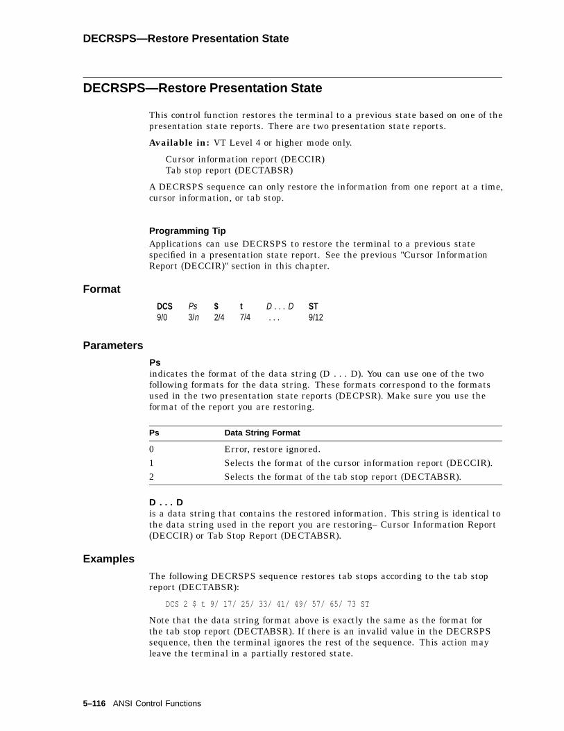
DECRSPS—Restore Presentation State
DECRSPS—Restore Presentation State
This control function restores the terminal to a previous state based on one of thepresentation state reports. There are two presentation state reports.
Available in: VT Level 4 or higher mode only.
Cursor information report (DECCIR)Tab stop report (DECTABSR)
A DECRSPS sequence can only restore the information from one report at a time,cursor information, or tab stop.
Programming TipApplications can use DECRSPS to restore the terminal to a previous statespecified in a presentation state report. See the previous "Cursor InformationReport (DECCIR)" section in this chapter.
Format
DCS9/0
Ps3/n
$2/4
t7/4
D . . . D. . .
ST9/12
Parameters
Psindicates the format of the data string (D . . . D). You can use one of the twofollowing formats for the data string. These formats correspond to the formatsused in the two presentation state reports (DECPSR). Make sure you use theformat of the report you are restoring.
Ps Data String Format
0 Error, restore ignored.1 Selects the format of the cursor information report (DECCIR).2 Selects the format of the tab stop report (DECTABSR).
D . . . Dis a data string that contains the restored information. This string is identical tothe data string used in the report you are restoring– Cursor Information Report(DECCIR) or Tab Stop Report (DECTABSR).
Examples
The following DECRSPS sequence restores tab stops according to the tab stopreport (DECTABSR):
DCS 2 $ t 9/ 17/ 25/ 33/ 41/ 49/ 57/ 65/ 73 ST
Note that the data string format above is exactly the same as the format forthe tab stop report (DECTABSR). If there is an invalid value in the DECRSPSsequence, then the terminal ignores the rest of the sequence. This action mayleave the terminal in a partially restored state.
5–116 ANSI Control Functions
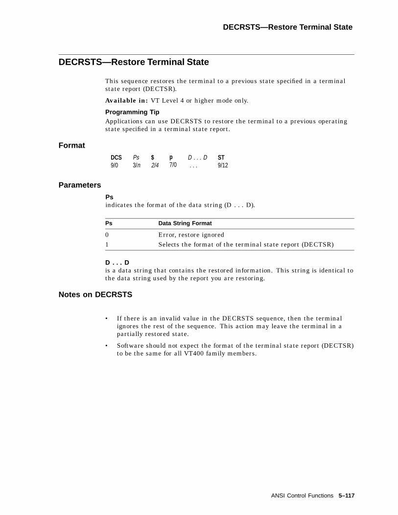
DECRSTS—Restore Terminal State
DECRSTS—Restore Terminal State
This sequence restores the terminal to a previous state specified in a terminalstate report (DECTSR).
Available in: VT Level 4 or higher mode only.
Programming TipApplications can use DECRSTS to restore the terminal to a previous operatingstate specified in a terminal state report.
Format
DCS9/0
Ps3/n
$2/4
p7/0
D . . . D. . .
ST9/12
Parameters
Psindicates the format of the data string (D . . . D).
Ps Data String Format
0 Error, restore ignored1 Selects the format of the terminal state report (DECTSR)
D . . . Dis a data string that contains the restored information. This string is identical tothe data string used by the report you are restoring.
Notes on DECRSTS
• If there is an invalid value in the DECRSTS sequence, then the terminalignores the rest of the sequence. This action may leave the terminal in apartially restored state.
• Software should not expect the format of the terminal state report (DECTSR)to be the same for all VT400 family members.
ANSI Control Functions 5–117

DECRSTS—Restore Terminal Color Table State
DECRSTS—Restore Terminal Color Table State
A host request to restore a color table.
Format
DCS9/0
23/2
$2/4
p7/0
D . . . D. . .
ST9/12
Parameters
D . . . Dis a data string that contains the groups of five parameters for each color map torestore as follows:
Pc; Pu; Px; Py; Pz / Pc; Pu; Px; Py; Pz / ...
where:Pc is the color number 0 -255.Pu is the color coordinate system.
1—HLS (hue 0-360, lightness 0-100, saturation 0-100)2—RGB (red 0-100, green 0-100, blue 0-100)
Px, Py, Pz are values in the color coordinate system.; is the semicolon (3/11)./ is the slash character (2/15).
Description
To load a previously reported color map, the host transmits a DECRSTS controlwith parameter 2 and the desired color map definitions in the data string. Whenloading a color map, only the index entries specified are changed. Also seeDECRQTSR and DECTSR for requesting color maps and the terminal’s report.
5–118 ANSI Control Functions

DECSACE—Select Attribute Change Extent
DECSACE—Select Attribute Change Extent
Selects which character positions within a rectangle are affected by an attributechange.
Available in: VT Level 4 or higher mode only
Format
CSI9/11
Ps3/n
*2/10
x7/8
Parameters
Psselects the area of character positions affected.
Ps Area Effected
0(default)
DECCARA or DECRARA affect the stream of character positionsthat begins with the first position specified in the DECCARA orDECRARA command, and ends with the second character positionspecified.
1 Same as 0.2 DECCARA and DECRARA affect all character positions in the
rectangular area. The DECCARA or DECRARA command specifiesthe top-left and bottom-right corners.
ANSI Control Functions 5–119
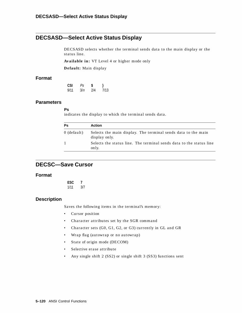
DECSASD—Select Active Status Display
DECSASD—Select Active Status Display
DECSASD selects whether the terminal sends data to the main display or thestatus line.
Available in: VT Level 4 or higher mode only
Default: Main display
Format
CSI9/11
Ps3/n
$2/4
}7/13
Parameters
Psindicates the display to which the terminal sends data.
Ps Action
0 (default) Selects the main display. The terminal sends data to the maindisplay only.
1 Selects the status line. The terminal sends data to the status lineonly.
DECSC—Save Cursor
Format
ESC1/11
73/7
Description
Saves the following items in the terminal’s memory:
• Cursor position
• Character attributes set by the SGR command
• Character sets (G0, G1, G2, or G3) currently in GL and GR
• Wrap flag (autowrap or no autowrap)
• State of origin mode (DECOM)
• Selective erase attribute
• Any single shift 2 (SS2) or single shift 3 (SS3) functions sent
5–120 ANSI Control Functions

DECSCA—Select Character Protection Attribute
DECSCA—Select Character Protection Attribute
DECSCA defines the characters that come after it as erasable or not erasablefrom the screen. The selective erase control functions (DECSED and DECSEL)can only erase characters defined as erasable.
Available in: VT Level 4 or higher mode only
Format
CSI9/11
Ps3/n
"2/2
q7/1
Parameters
Psdefines all characters that follow the DECSCA function as erasable or noterasable.
Ps Meaning
0 (default) DECSED and DECSEL can erase characters.1 DECSED and DECSEL cannot erase characters.2 Same as 0.
Note on DECSCA
DECSCA does not effect visual character attributes set by the select graphicrendition (SGR) function.
ANSI Control Functions 5–121

DECSCL—Select Conformance Level
DECSCL—Select Conformance Level
Using DECSCL, you can select the terminal’s conformance level. The factorydefault for the VT500 family is level 5 (VT Level 5 mode, 8-bit controls).
Note
When you change the operating level, the terminal performs a hard reset(RIS).
Format
Sequence Level Selected
Level 1
CSI9/11
63/6
13/1
"2/2
p7/0
VT100 mode
Level 5†
CSI9/11
63/6
n3/n
"2/2
p7/0
VT Level 5 mode, 8-bit controls
CSI9/11
63/6
n3/n
;3/11
03/0
"2/2
p7/0
VT Level 5 mode, 8-bit controls
CSI9/11
63/6
n3/n
;3/11
13/2
"2/2
p7/0
VT Level 5 mode, 7-bit controls
CSI9/11
63/6
n3/n
;3/11
23/2
"2/2
p7/0
VT Level 5 mode, 8-bit controls
†Level 5 includes levels 2, 3, and 4. In these sequences, n can be 2, 3, 4, or 5.
5–122 ANSI Control Functions

DECSCLM—Scrolling Mode
DECSCLM—Scrolling Mode
This control function selects the way the terminal scrolls lines. You can select oneof two scroll settings, smooth or jump.
Default: Smooth scroll.
Format
CSI9/11
?3/15
43/4
h6/8
Set: smooth scroll.
CSI9/11
?3/15
43/4
l6/12
Reset: jump scroll.
Description
When DECSLM is set, the terminal adds lines to the screen at a moderate,smooth rate. You can select a slow rate or fast rate in Display Set-Up.
When DECSLM is reset, the terminal can add lines to the screen as fast as itreceives them.
DECSCNM—Screen Mode: Light or Dark Screen
This control function selects a dark or light background on the screen.
Default: Dark background.
Format
CSI9/11
?3/15
53/5
h6/8
Set: reverse video.
CSI9/11
?3/15
53/5
l6/12
Reset: normal display.
Description
When DECSCNM is set, the screen displays dark characters on a lightbackground.
When DECSCNM is reset, the screen displays light characters on a darkbackground.
Note on DECSCNM
Screen mode only effects how the data appears on the screen. DECSCNM doesnot change the data in page memory.
ANSI Control Functions 5–123
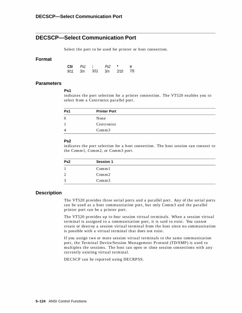
DECSCP—Select Communication Port
DECSCP—Select Communication Port
Select the port to be used for printer or host connection.
Format
CSI9/11
Ps13/n
;3/11
Ps23/n
*2/10
u7/5
Parameters
Ps1indicates the port selection for a printer connection. The VT520 enables you toselect from a Centronics parallel port.
Ps1 Printer Port
0 None1 Centronics4 Comm3
Ps2indicates the port selection for a host connection. The host session can connect tothe Comm1, Comm2, or Comm3 port.
Ps2 Session 1
1 Comm12 Comm23 Comm3
Description
The VT520 provides three serial ports and a parallel port. Any of the serial portscan be used as a host communication port, but only Comm3 and the parallelprinter port can be a printer port.
The VT520 provides up to four session virtual terminals. When a session virtualterminal is assigned to a communication port, it is said to exist. You cannotcreate or destroy a session virtual terminal from the host since no communicationis possible with a virtual terminal that does not exist.
If you assign two or more session virtual terminals to the same communicationport, the Terminal Device/Session Management Protocol (TD/SMP) is used tomultiplex the sessions. The host can open or close session connections with anycurrently existing virtual terminal.
DECSCP can be reported using DECRPSS.
5–124 ANSI Control Functions
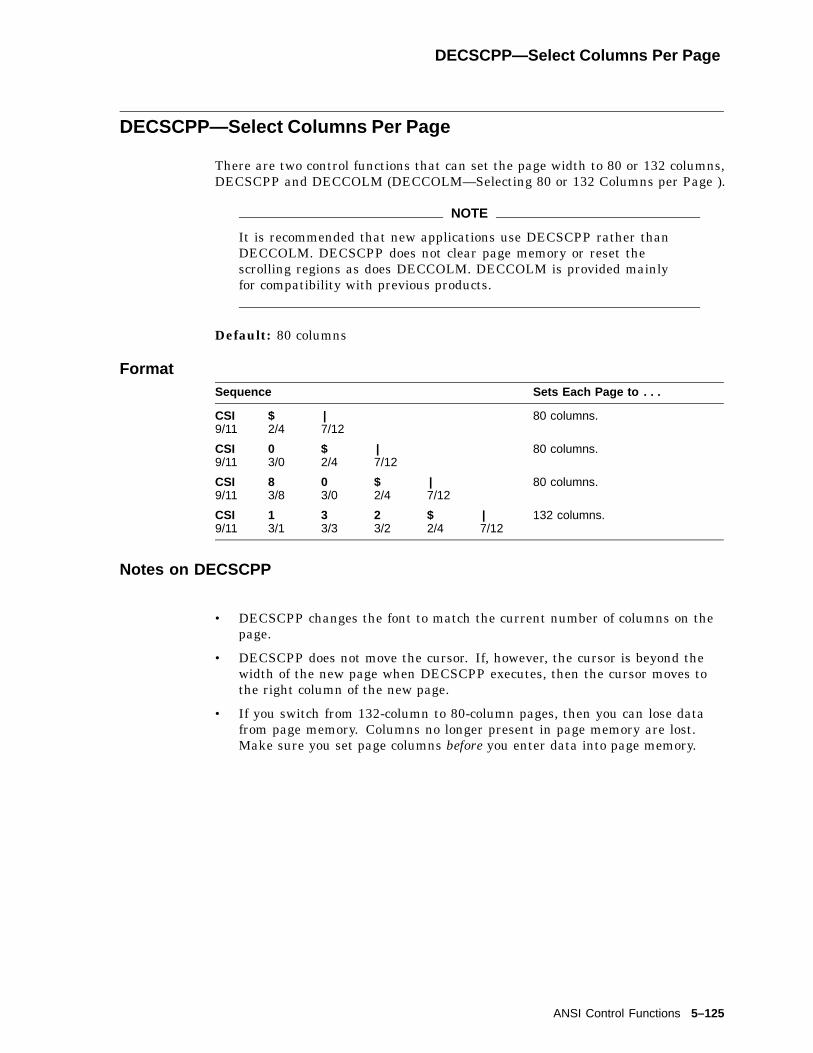
DECSCPP—Select Columns Per Page
DECSCPP—Select Columns Per Page
There are two control functions that can set the page width to 80 or 132 columns,DECSCPP and DECCOLM (DECCOLM—Selecting 80 or 132 Columns per Page ).
NOTE
It is recommended that new applications use DECSCPP rather thanDECCOLM. DECSCPP does not clear page memory or reset thescrolling regions as does DECCOLM. DECCOLM is provided mainlyfor compatibility with previous products.
Default: 80 columns
FormatSequence Sets Each Page to . . .
CSI9/11
$2/4
|7/12
80 columns.
CSI9/11
03/0
$2/4
|7/12
80 columns.
CSI9/11
83/8
03/0
$2/4
|7/12
80 columns.
CSI9/11
13/1
33/3
23/2
$2/4
|7/12
132 columns.
Notes on DECSCPP
• DECSCPP changes the font to match the current number of columns on thepage.
• DECSCPP does not move the cursor. If, however, the cursor is beyond thewidth of the new page when DECSCPP executes, then the cursor moves tothe right column of the new page.
• If you switch from 132-column to 80-column pages, then you can lose datafrom page memory. Columns no longer present in page memory are lost.Make sure you set page columns before you enter data into page memory.
ANSI Control Functions 5–125

DECSCS—Select Communication Speed
DECSCS—Select Communication Speed
Select a communication speed for a communication line.
Format
CSI9/11
Ps13/n
;3/11
Ps23/n
*2/10
r7/2
Parameters
Ps1indicates the communication line.
Ps1 Comm Line Type
1, 0 or none Host Transmit2 Host Receive3 Printer4 Modem Hi5 Modem Low
Ps2indicates the communication speed.
Ps2 Speed Ps2 Speed
0 or none default 6 96001 300 7 192002 600 8 384003 1200 9 576004 2400 10 768005 4800 11 115200
The default value depends on the type of communication line.
Communication Line Default Communication Speed
Host Transmit 9600Host Receive Receive=transmitPrinter 4800Modem Hi IgnoreModem Low Ignore
5–126 ANSI Control Functions

DECSCUSR—Set Cursor Style
DECSCUSR—Set Cursor Style
Select the style of the cursor on the screen.
Format
CSI9/11
Ps3/n
SP2/0
q7/1
Parameters
Psindicates the style of the cursor.
Ps Cursor Style
0, 1 or none Blink Block (Default)2 Steady Block3 Blink Underline4 Steady Underline
This sequence causes the cursor to be displayed in a different style when thecursor is enabled.
Note on DECSCUSR
The escape sequence DECTCEM can enable or disable the cursor display.
ANSI Control Functions 5–127
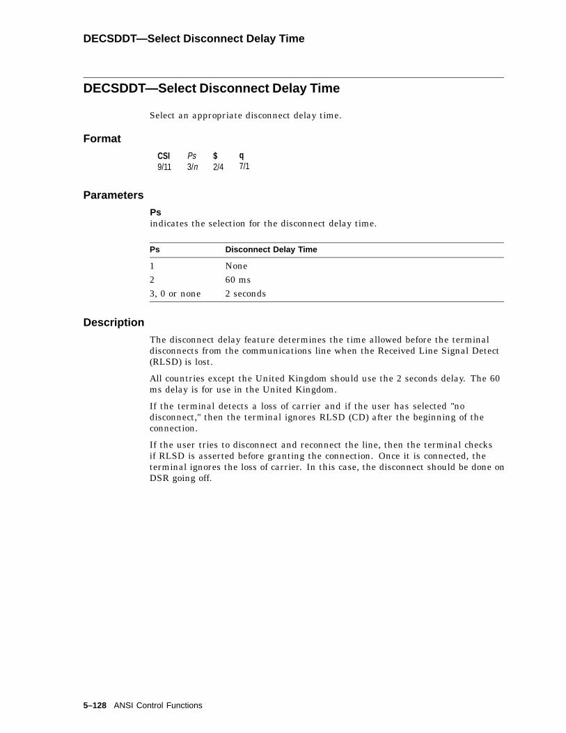
DECSDDT—Select Disconnect Delay Time
DECSDDT—Select Disconnect Delay Time
Select an appropriate disconnect delay time.
Format
CSI9/11
Ps3/n
$2/4
q7/1
Parameters
Psindicates the selection for the disconnect delay time.
Ps Disconnect Delay Time
1 None2 60 ms3, 0 or none 2 seconds
Description
The disconnect delay feature determines the time allowed before the terminaldisconnects from the communications line when the Received Line Signal Detect(RLSD) is lost.
All countries except the United Kingdom should use the 2 seconds delay. The 60ms delay is for use in the United Kingdom.
If the terminal detects a loss of carrier and if the user has selected "nodisconnect," then the terminal ignores RLSD (CD) after the beginning of theconnection.
If the user tries to disconnect and reconnect the line, then the terminal checksif RLSD is asserted before granting the connection. Once it is connected, theterminal ignores the loss of carrier. In this case, the disconnect should be done onDSR going off.
5–128 ANSI Control Functions
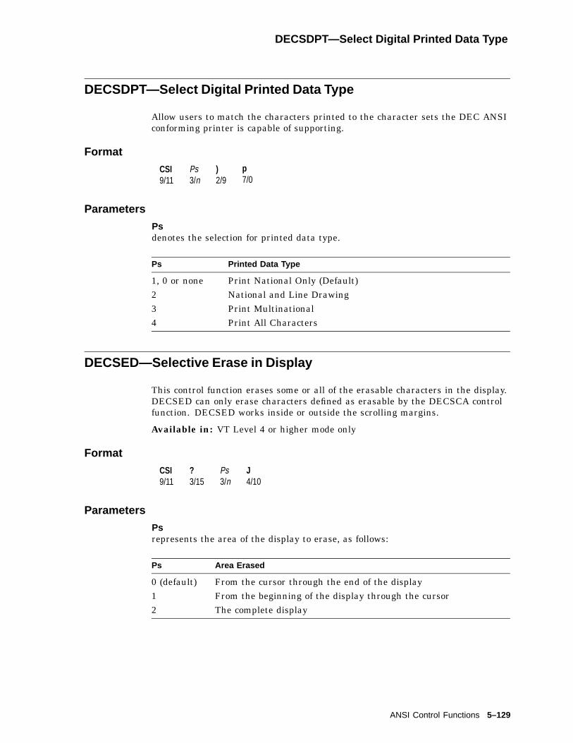
DECSDPT—Select Digital Printed Data Type
DECSDPT—Select Digital Printed Data Type
Allow users to match the characters printed to the character sets the DEC ANSIconforming printer is capable of supporting.
Format
CSI9/11
Ps3/n
)2/9
p7/0
Parameters
Psdenotes the selection for printed data type.
Ps Printed Data Type
1, 0 or none Print National Only (Default)2 National and Line Drawing3 Print Multinational4 Print All Characters
DECSED—Selective Erase in Display
This control function erases some or all of the erasable characters in the display.DECSED can only erase characters defined as erasable by the DECSCA controlfunction. DECSED works inside or outside the scrolling margins.
Available in: VT Level 4 or higher mode only
Format
CSI9/11
?3/15
Ps3/n
J4/10
Parameters
Psrepresents the area of the display to erase, as follows:
Ps Area Erased
0 (default) From the cursor through the end of the display1 From the beginning of the display through the cursor2 The complete display
ANSI Control Functions 5–129

DECSEST—Energy Saver Timing
DECSEST—Energy Saver Timing
Selects the energy saver timing.
Default: 15 minutes
Format
CSI9/11
Ps-2/13
r7/2
Parameters
PsEnergy Saver Timing
Ps Selection
0 Never5 5 minutes15 15 minutes30 30 minutes
Description
The Energy saver feature switches the monitor to suspend mode after thespecified interval of CRT saver active. The energy saver is disabled if the CRTsaver is set to never. Refer to the Set-Up chapter for details.
DECSEST can be reported using DECRPSS.
5–130 ANSI Control Functions

DECSEL—Selective Erase in Line
DECSEL—Selective Erase in Line
This control function erases some or all of the erasable characters in a single lineof text. DECSEL erases only those characters defined as erasable by the DECSCAcontrol function. DECSEL works inside or outside the scrolling margins.
Available in: VT Level 4 or higher mode only
Format
CSI9/11
?3/15
Ps3/n
K4/11
Parameters
Psrepresents the section of the line to erase, as follows:
Ps Section Erased
0 (default) From the cursor through the end of the line1 From the beginning of the line through the cursor2 The complete line
ANSI Control Functions 5–131

DECSERA—Selective Erase Rectangular Area
DECSERA—Selective Erase Rectangular Area
This control function erases all erasable characters from a specified rectangulararea in page memory. The select character protection attribute (DECSCA) controlfunction defines whether or not DECSERA can erase characters.
When an area is erased, DECSERA replaces character positions with the spacecharacter (2/0). DECSERA does not change:
• Visual attributes set by the select graphic rendition (SGR) function
• Protection attributes set by DECSCA
• Line attributes
Available in: VT Level 4 or higher mode only
Format
CSI9/11
Pt3/n
;3/11
Pl3/n
;3/11
Pb3/n
;3/11
Pr3/n
$2/4
{7/11
Parameters
Pt, Pl, Pb, and Prdefine the rectangular area to be selectively erased:
Pt is the top-line border. Pt must be less than or equal to Pb.Default: Pt = 1.
Pl is the left-column border. Pl must be less than or equal to Pr.Default: Pl = 1.
Pb is the bottom-line border.Default: Pb = the last line of the active page.
Pr is the right-column border.Default: Pr = the last column of the active page.
Notes on DECSERA
• The coordinates of the rectangular area are affected by the setting of originmode (DECOM).
• DECSERA is not affected by the page margins.
• If the value of Pt, Pl, Pb, or Pr exceeds the width or height of the active page,then the value is treated as the width or height of that page.
• DECSERA does not change the active cursor position.
5–132 ANSI Control Functions
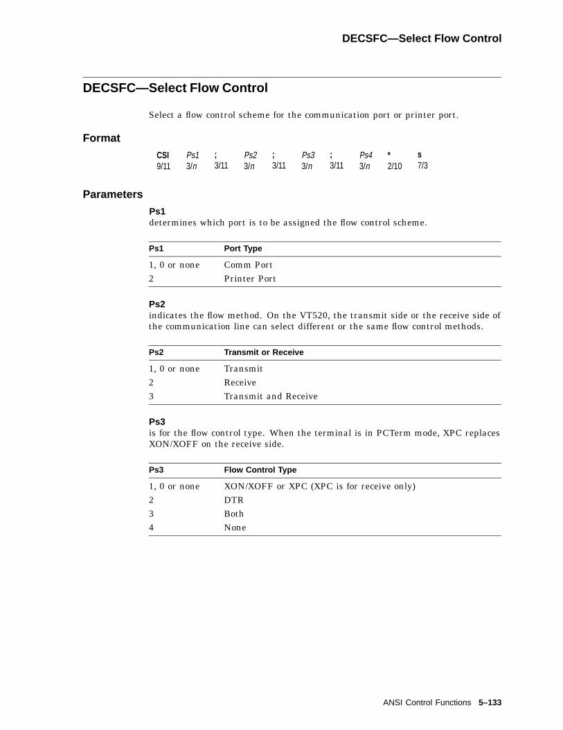
DECSFC—Select Flow Control
DECSFC—Select Flow Control
Select a flow control scheme for the communication port or printer port.
Format
CSI9/11
Ps13/n
;3/11
Ps23/n
;3/11
Ps33/n
;3/11
Ps43/n
*2/10
s7/3
Parameters
Ps1determines which port is to be assigned the flow control scheme.
Ps1 Port Type
1, 0 or none Comm Port2 Printer Port
Ps2indicates the flow method. On the VT520, the transmit side or the receive side ofthe communication line can select different or the same flow control methods.
Ps2 Transmit or Receive
1, 0 or none Transmit2 Receive3 Transmit and Receive
Ps3is for the flow control type. When the terminal is in PCTerm mode, XPC replacesXON/XOFF on the receive side.
Ps3 Flow Control Type
1, 0 or none XON/XOFF or XPC (XPC is for receive only)2 DTR3 Both4 None
ANSI Control Functions 5–133

DECSFC—Select Flow Control
Ps4sets the flow control threshold.
Ps4 Flow Control Threshold
1, 0 or none Low (64)2 High (768)
The terminal uses "low" and "high" to denote the flow control threshold.
• If Low is selected, then the terminal sends an XOFF (if in software flowcontrol) or lower DTR (in hardware flow control) to notify the host of holdingtransmission when the input buffer reaches 64 bytes.
• If High is selected, then 768 bytes is the flow control threshold.
"High" flow control threshold is not available for the printer port, which alwaysuses low (64 bytes) as the flow control threshold.
DECSIN—Set Icon Name
Specifies a descriptive name, up to 12 characters, for this session’s icon, using anOSC string.
Format
OSC9/13
23/2
D...D ST9/12
Where D...D is:
L4/12
;3/11
<name>
Description
DECSIN specifies a descriptive name, up to 12 characters, for this session’s icon.
There is no TSI report for the session icon name.
5–134 ANSI Control Functions

DECSKCV—Set Key Click Volume
DECSKCV—Set Key Click Volume
Set the keyclick volume.
Format
CSI9/11
Ps3/n
SP2/0
r7/2
Parameters
Psindicates the selection of the click volume.
Ps Key Click Volume
1 Off2, 3, 4 Low5, 6, 7, 8, 0 or none High (Default)
DECSLCK—Set Lock Key Style
Allow the host to control the Caps Lock key.
Format
CSI9/11
PsPs
SP2/0
v7/6
Parameters
Psindicates the selection of the Caps Lock key.
Ps Lock Style Meaning
1, 0 or None Caps Lock (Default) Lock alpha keys on main keypad inuppercase.
2 Shift Lock Lock alpha and numeric keys on mainkeypad in shifted setting.
3 Reverse Lock Works the same as Caps Lock, exceptthat pressing Shift while Reverse Lockis active will send the lowercase orunshifted character assigned to a key.Thus, the lock state is reversible.
ANSI Control Functions 5–135
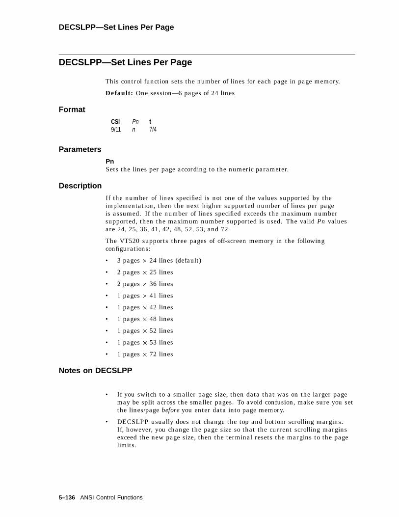
DECSLPP—Set Lines Per Page
DECSLPP—Set Lines Per Page
This control function sets the number of lines for each page in page memory.
Default: One session—6 pages of 24 lines
Format
CSI9/11
Pnn
t7/4
Parameters
PnSets the lines per page according to the numeric parameter.
Description
If the number of lines specified is not one of the values supported by theimplementation, then the next higher supported number of lines per pageis assumed. If the number of lines specified exceeds the maximum numbersupported, then the maximum number supported is used. The valid Pn valuesare 24, 25, 36, 41, 42, 48, 52, 53, and 72.
The VT520 supports three pages of off-screen memory in the followingconfigurations:
• 3 pages � 24 lines (default)
• 2 pages � 25 lines
• 2 pages � 36 lines
• 1 pages � 41 lines
• 1 pages � 42 lines
• 1 pages � 48 lines
• 1 pages � 52 lines
• 1 pages � 53 lines
• 1 pages � 72 lines
Notes on DECSLPP
• If you switch to a smaller page size, then data that was on the larger pagemay be split across the smaller pages. To avoid confusion, make sure you setthe lines/page before you enter data into page memory.
• DECSLPP usually does not change the top and bottom scrolling margins.If, however, you change the page size so that the current scrolling marginsexceed the new page size, then the terminal resets the margins to the pagelimits.
5–136 ANSI Control Functions

DECSLRM—Set Left and Right Margins
DECSLRM—Set Left and Right Margins
This control function sets the left and right margins to define the scrolling region.DECSLRM only works when vertical split screen mode (DECLRMM) is set.
Available in: VT Level 4 or higher mode onlyDefault: Margins are at the left and right page borders.
Format
CSI9/11
Pl3/n
;3/11
Pr3/n
s7/3
Parameters
Plis the column number for the left margin.Default: Pl = 1.
Pris the column number for the right margin.Default: Pr = 80 or 132 (depending on the page width).
Notes on DECSLRM
• The value of the left margin (Pl) must be less than the right margin (Pr).
• The maximum size of the scrolling region is the page size, based on thesetting of set columns per page (DECSCPP).
• The minimum size of the scrolling region is two columns.
• The terminal only recognizes this control function if vertical split screen mode(DECLRMM) is set.
• DECSLRM moves the cursor to column 1, line 1 of the page.
• If the left and right margins are set to columns other than 1 and 80 (or 132),then the terminal cannot scroll smoothly.
ANSI Control Functions 5–137
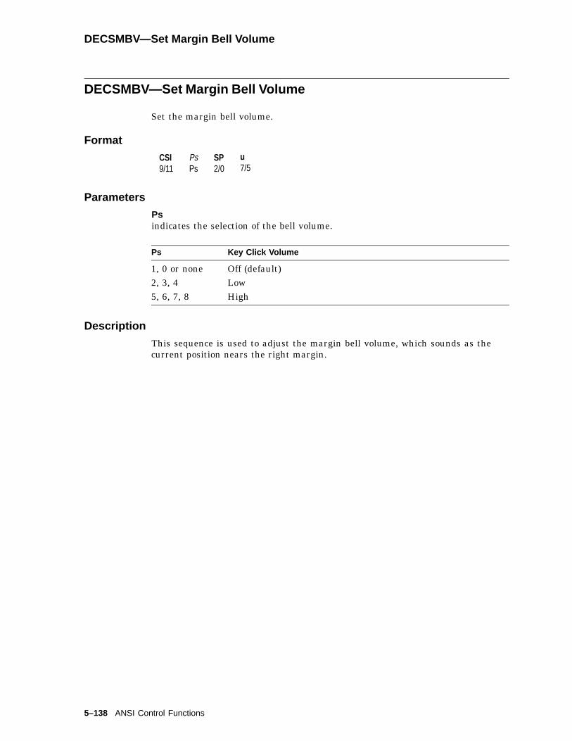
DECSMBV—Set Margin Bell Volume
DECSMBV—Set Margin Bell Volume
Set the margin bell volume.
Format
CSI9/11
PsPs
SP2/0
u7/5
Parameters
Psindicates the selection of the bell volume.
Ps Key Click Volume
1, 0 or none Off (default)2, 3, 4 Low5, 6, 7, 8 High
Description
This sequence is used to adjust the margin bell volume, which sounds as thecurrent position nears the right margin.
5–138 ANSI Control Functions
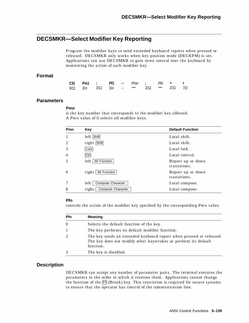
DECSMKR—Select Modifier Key Reporting
DECSMKR—Select Modifier Key Reporting
Program the modifier keys to send extended keyboard reports when pressed orreleased. DECSMKR only works when key position mode (DECKPM) is set.Applications can use DECSMKR to gain more control over the keyboard bymonitoring the action of each modifier key.
Format
CSI9/11
Pm13/n
;3/11
Pf13/n
...
...Pmn***
;3/11
Pfn***
+2/11
r7/2
Parameters
Pmnis the key number that corresponds to the modifier key affected.A Pmn value of 0 selects all modifier keys.
Pmn Key Default Function
1 left Shift Local shift.2 right Shift Local shift.3 Lock Local lock.4 Ctrl Local control.5 left Alt Function Report up or down
transitions.6 right Alt Function Report up or down
transitions.7 left Compose Character Local compose.8 right Compose Character Local compose.
Pfncontrols the action of the modifier key specified by the corresponding Pmn value.
Pfn Meaning
0 Selects the default function of the key.1 The key performs its default modifier function.2 The key sends an extended keyboard report when pressed or released.
The key does not modify other keystrokes or perform its defaultfunction.
3 The key is disabled.
Description
DECSMKR can accept any number of parameter pairs. The terminal executes theparameters in the order in which it receives them. Applications cannot changethe function of the F5 (Break) key. This restriction is required for secure systemsto ensure that the operator has control of the communication line.
ANSI Control Functions 5–139

DECSNLS—Set Number of Lines Per Screen
DECSNLS—Set Number of Lines Per Screen
Set the maximum lines that can be displayed on the screen.
Format
CSI9/11
Pn. . .
*2/10
|7/12
Description
The terminal supports three different font heights, which allows 26, 42, or 53data lines to be displayed on the screen or 25, 41, or 52 data lines to be displayedon the screen, plus a status line. The different character fonts are:
80/26 132/26 80/42 132/42 80/53 132/53
Cell Width 10 6 10 6 10 6Cell Height 16 16 10 10 8 8
Valid Combinations
The terminal has the following valid combinations:
Lines Per Screen Refresh Rate Overscan
26 72 Hz No26 72 Hz Yes26 60 Hz No26 60 Hz Yes42 72 Hz No42 60 Hz No42 60 Hz Yes53 72 Hz No53 60 Hz No53 60 Hz Yes
If an invalid combination is selected, the terminal automatically returns to avalid combination according to the following priority order:
1. Lines Per Screen
2. Refresh Rate
3. Overscan
5–140 ANSI Control Functions

DECSNLS—Set Number of Lines Per Screen
Examples
The current combination is 26 lines/72 Hz/Overscan. If you attempt to assign 42lines per screen, then the terminal becomes 42 lines/72 Hz/No Overscan.
The current combination is 42 lines/60 Hz/Overscan. If you attempt to assign 72Hz refresh rate, then the terminal becomes 42 lines/72 Hz/No Overscan.
The current combination is 53 lines/72 Hz/No Overscan. Any attempt to enableOverscan is invalid.
DECSPMA—Session Page Memory Allocation
Allocates 25 line pages to each session according to the corresponding parameters.
Format
CSI9/12
Pn1; Pn2; Pn3; Pn4;,2/12
x7/8
Description
Pages are allocated for each session in order (1 through 4). An omitted parameterleaves the previous allocation unchanged. A parameter larger than the numberof pages available leaves the previous allocation for that session unchanged. Noactual pages are allocated to disabled sessions, but the allocation is changed thenext time the session is enabled.
DECSPMA can be reported using DECRPSS.
ANSI Control Functions 5–141

DECSPP—Set Port Parameters
DECSPP—Set Port Parameters
Configures communication parameters for either a communication port or aprinter port.
Format
CSI9/11
Ps13/n
;3/11
Ps23/n
;3/11
Ps33/n
;3/11
Ps43/n
+2/11
w7/7
Parameters
Ps1determines which port is to be configured.
Ps1 Port Selection
1, 0 or none Comm Port2 Printer Port
Ps2determines the data bit.
Ps2 Data Bit
1, 0 or none 8 bits2 7 bits
Ps3determines the parity.
Ps3 Parity Ps3 Parity
1, 0 or none No Parity 5 Odd Parity, Unchecked2 Even Parity 6 Mark Parity3 Odd Parity 7 Space Parity4 Even Parity,
Unchecked
Ps3 selections 4 and 5 are not available for the printer port.
Ps4determines the stop bit.
Ps4 Stop Bit
1, 0 or none 1 bit2 2 bits
5–142 ANSI Control Functions

DECSPPCS—Select ProPrinter Character Set
DECSPPCS—Select ProPrinter Character Set
Allow users to match the characters printed to the character sets the IBMProPrinter is capable of supporting.
Format
CSI9/11
Pn3/n
*2/10
p7/0
Parameters
Pndenotes the code page numbers for ProPrinter supported character sets.
Pn Printer
210 PC Greek220 PC Spanish437 PC International850 PC Multilingual852 PC Slavic (Latin 2)857 PC Turkish860 PC Portuguese862 PC Hebrew863 PC French-Canadian865 PC Danish866 PC Cyrillic
Description
This sequence takes affect only when the printer type (DECSPRTT) is set to "IBMProPrinter" or "DEC + IBM."
ANSI Control Functions 5–143

DECSPRTT—Select Printer Type
DECSPRTT—Select Printer Type
Allow users to select a printer type that matches their environment.
Format
CSI9/11
Ps3/n
$2/4
s7/3
Parameters
Psindicates the selection of the printer type.
Ps Printer Type
1, 0 or none DEC ANSI (default)2 IBM ProPrinter3 DEC + IBM
Description
Printer type "DEC ANSI" indicates a printer type that is capable of recognizingDigital ANSI conforming escape sequences.
"ProPrinter" indicates an attached printer type that recognizes the IBMProPrinter escape sequences.
If the attached printer is an ANSI-compatible printer that has the IBMProPrinter emulation feature, then select "DEC + IBM."
DECSR—Secure Reset
This control function sets the terminal to its power-up state. DECSR letsapplications know the exact state of the terminal before any attemptedoperations. You can use DECSR to guarantee the terminal state for secureconnections. DECSR is similar to RIS, but does not perform a disconnect fromthe host.
Format
CSI9/11
Pr3/n
+2/11
p7/0
Parameters
Pris a optional random number from 0 to 16383. If Pr is included, then the terminalsends a confirmation (DECSRC) with this number.
5–144 ANSI Control Functions

DECSR—Secure Reset
DECSR Actions
• Clears user-defined keys.
• Clears soft character sets.
• Clears the screen and all off-screen page memory.
• Returns the cursor to the upper-left corner of the first page.
• Resets the scrolling margins.
• Resets origin mode (DECOM) to absolute.
• Sets visual character attributes to normal.
• Sets the selective erase (DECSCA) attribute to not selectively erasable.
• Sets all character sets to the defaults (G0, G1, G2, G3, GL, GR).
• Erases macro memory.
• Erases the paste buffer.
• Reinitializes the keyboard state by:
– Clearing the keyboard input buffer
– Canceling compose sequences
– Resetting the keyboard to send its default codes (in NVR)
– Unlocking the keyboard (resetting KAM)
DECSR replaces all set-up parameters to their saved settings or power-up defaultvalues. If you include the optional Pr parameter, then the terminal returns asecure reset report to the host.
Notes on DECSR
• DECSR works in all conformance levels (level 1 or higher).
• DECSR works in display controls mode (CRM) and causes the terminal to exitthis mode.
• DECSR does not work in VT52 mode or printer controller mode. The hostsoftware must explicitly exit these modes. You can send DECSR to anattached printer if the terminal is in printer controller mode.
• The terminal buffers DECSR like any other incoming data.
ANSI Control Functions 5–145

DECSRC—Secure Reset Confirmation
DECSRC—Secure Reset Confirmation
The terminal returns this report to the host if the Pr parameter was included inthe last secure reset (DECSR) control function. DECSRC report indicates thatthe secure reset operation was successful.
Format
CSI9/11
Pr3/n
*2/10
q7/1
Parameters
Pris the number from 0 to 16383 that was included in the corresponding securereset sequence.
DECSSCLS—Set Scroll Speed
Select how fast lines appear on the screen.
Format
CSI9/11
PsPs
SP2/0
p7/0
Parameters
Psindicates the scroll speed and lines per second.
Ps Scroll Speed Lines per Second
0, 1, 2, 3 or none Smooth 2 (default) 94, 5, 6, 7, 8 Smooth 4 189 Jump As fast as received
Description
This is a user preference feature. If the User Features Locked is enabled, thenthe scroll speed cannot be changed by this control function.
The escape sequence DECSCLM can change the scroll speed between Smooth 2and Jump scroll.
5–146 ANSI Control Functions

DECSSDT—Select Status Display (Line) Type
DECSSDT—Select Status Display (Line) Type
This control function lets the host select the type of status line displayed.
Available in: VT Level 4 or higher mode only
Default: Indicator status display
Format
CSI9/11
Ps3/n
$2/4
~7/14
Parameters
Psindicates which status line the host selects:
Ps Status Line Selected
0 (default) No status line1 Indicator status line2 Host-writable status line
Notes on DECSSDT
• If you select no status line (Ps = 0), then the terminal uses the line as anadditional user window line to display data.
• If you change from an indicator to a host-writable status line, then the newhost-writable status line is empty.
• When you select the host-writable status line, most of the control functionsthat affect the main display also affect the status line. The following listdescribes the exceptions to the rule:
Control Function Action
Select character set(SCS)
Both the main display and status line use thesame character set.
Cursor position controls Only the column parameters in cursor-positioning commands operate in the statusline.
ANSI mode (DECANM) Ignored if received in the status line.Set conformance level(DECSCL)
Exits the status line.
Scrolling mode(DECSCLM)
Affects the main display and the status line.
Soft terminal reset(DECSTR)
Exits the status line.
ANSI Control Functions 5–147
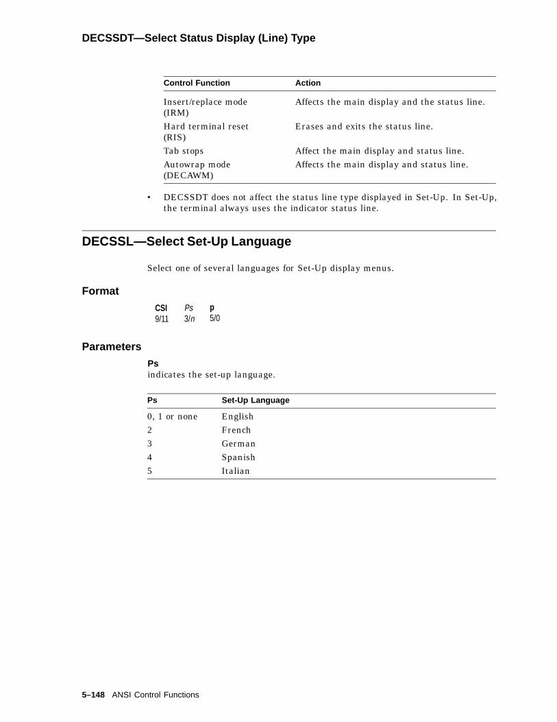
DECSSDT—Select Status Display (Line) Type
Control Function Action
Insert/replace mode(IRM)
Affects the main display and the status line.
Hard terminal reset(RIS)
Erases and exits the status line.
Tab stops Affect the main display and status line.Autowrap mode(DECAWM)
Affects the main display and status line.
• DECSSDT does not affect the status line type displayed in Set-Up. In Set-Up,the terminal always uses the indicator status line.
DECSSL—Select Set-Up Language
Select one of several languages for Set-Up display menus.
Format
CSI9/11
Ps3/n
p5/0
Parameters
Psindicates the set-up language.
Ps Set-Up Language
0, 1 or none English2 French3 German4 Spanish5 Italian
5–148 ANSI Control Functions
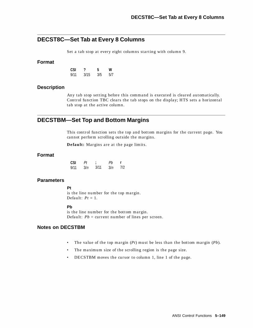
DECST8C—Set Tab at Every 8 Columns
DECST8C—Set Tab at Every 8 Columns
Set a tab stop at every eight columns starting with column 9.
Format
CSI9/11
?3/15
53/5
W5/7
Description
Any tab stop setting before this command is executed is cleared automatically.Control function TBC clears the tab stops on the display; HTS sets a horizontaltab stop at the active column.
DECSTBM—Set Top and Bottom Margins
This control function sets the top and bottom margins for the current page. Youcannot perform scrolling outside the margins.
Default: Margins are at the page limits.
Format
CSI9/11
Pt3/n
;3/11
Pb3/n
r7/2
Parameters
Ptis the line number for the top margin.Default: Pt = 1.
Pbis the line number for the bottom margin.Default: Pb = current number of lines per screen.
Notes on DECSTBM
• The value of the top margin (Pt) must be less than the bottom margin (Pb).
• The maximum size of the scrolling region is the page size.
• DECSTBM moves the cursor to column 1, line 1 of the page.
ANSI Control Functions 5–149

DECSTR—Soft Terminal Reset
DECSTR—Soft Terminal Reset
Perform a soft reset to the default values listed in Table 5–6.
Format
CSI9/11
!2/1
p7/0
Description
Table 5–6 lists the terminal’s default settings:
Table 5–6 Terminal’s Default Settings
Mode Mnemonic State after DECSTR
Text cursor enable DECTCEM Cursor enabled.Insert/replace IRM Replace mode.Origin DECOM Absolute (cursor origin at
upper-left of screen. )Autowrap DECAWM No autowrap.National replacementcharacter set
DECNRCM Multinational set.
Keyboard action AM Unlocked.Numeric keypad DECNKM Numeric characters.Cursor keys DECCKM Normal (arrow keys).Set top and bottom margins DECSTBM Top margin = 1; bottom margin
= page length.All character sets G0, G1, G2,
G3, GL, GRDefault settings.
Select graphic rendition SGR Normal rendition.Select character attribute DECSCA Normal (erasable by DECSEL
and DECSED).Save cursor state DECSC Home position.Assign user preferencesupplemental set
DECAUPSS Set selected in Set-Up.
Select active status display DECSASD Main display.Keyboard position mode DECKPM Character codes.Cursor direction DECRLM Reset (Left-to-right), regardless
of NVR setting.PC Term mode DECPCTERM Always reset.
5–150 ANSI Control Functions

DECSTGLT—Select Color Look-Up Table
DECSTGLT—Select Color Look-Up Table
Selects the color mode or mapping.
Default: ANSI SGR color
Format
CSI9/11
Ps)2/9
{7/11
Parameters
PsLook-Up Table
Ps Selection To select colors, the terminal uses . . .
0 Mono Monochrome or gray level color map1 Alternate color Text attributes (bold, blink, underline,
reverse)2 Alternate color -3 ANSI SGR color ANSI SGR color parameters
Description
DECSTGLT selects the color mode or mapping used to display text colors andattributes. Refer to Color . Select color mode in Set-Up chapter for details.
DECSTGLT can be reported using DECRPSS.
ANSI Control Functions 5–151

DECSTRL—Set Transmit Rate Limit
DECSTRL—Set Transmit Rate Limit
Limit the rate of character transmission according to the selected rate.
Format
CSI9/11
Ps13/n
;3/11
Ps23/n
"2/2
u7/5
Parameters
Ps1indicates the key type.
Ps1 Key Type
1, 0 or none All Keys2 Graphic Key3 Function Key
Ps2indicates the characters per second.
Ps2 Characters Per Second
1, 0 or none 150 CPS2 50 CPS3 30 CPS
Description
When enabled, the terminal limits the rate at which it transmits the answerback,CPR, DA, TSI, and DSR messages, as well as the keyboard keys, and any othercharacters transmitted from the terminal. All messages and keystrokes aretransmitted according to the selected "character per second" rate.
You can select different transmit rates for graphic keys and function keys, whichusually transmit more than one byte at a time.
The transmit rate limit function can be enabled and disabled through theDECXRLM control function. When disabled, all messages and keystrokes aretransmitted as fast as possible without any delay between characters.
5–152 ANSI Control Functions

DECSTUI—Setting Terminal Unit ID
DECSTUI—Setting Terminal Unit ID
DECSTUI writes the terminal unit ID into the terminal’s NVR. The host can readthe ID with the tertiary device attribute (DA3).
Format
DCS9/0
!2/1
{7/11
D . . . D. . .
ST9/12
Parameters
D...Dis the terminal’s unit ID, consisting of four hexadecimal pairs. The first pairrepresents the manufacturing site code. The last three pairs represent an ID,which is unique for all terminals manufactured at a specific site. See tertiary DA(DA3) for more information.
Description
DECSTUI writes the terminal unit ID into the terminal’s nonvolatile randomaccess memory (NVR).
Available in: VT Level 4 or higher mode only.
Note on DECSTUI
Under normal operations the terminal ignores DECSTUI. DECSTUI works onlywhen the non-volatile memory checksum is invalid or a small jumper inside theterminal is activated, and the terminal is set to VT Level 4 mode.
ANSI Control Functions 5–153
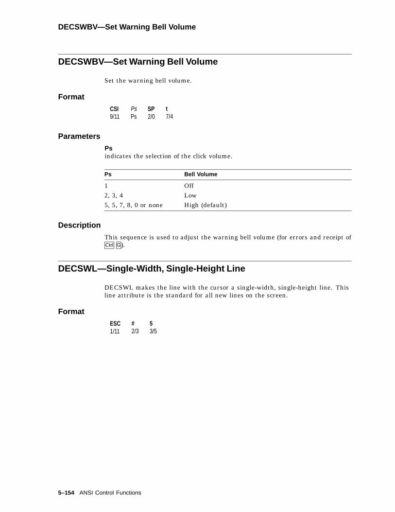
DECSWBV—Set Warning Bell Volume
DECSWBV—Set Warning Bell Volume
Set the warning bell volume.
Format
CSI9/11
PsPs
SP2/0
t7/4
Parameters
Psindicates the selection of the click volume.
Ps Bell Volume
1 Off2, 3, 4 Low5, 5, 7, 8, 0 or none High (default)
Description
This sequence is used to adjust the warning bell volume (for errors and receipt ofCtrl G).
DECSWL—Single-Width, Single-Height Line
DECSWL makes the line with the cursor a single-width, single-height line. Thisline attribute is the standard for all new lines on the screen.
Format
ESC1/11
#2/3
53/5
5–154 ANSI Control Functions

DECSZS—Select Zero Symbol
DECSZS—Select Zero Symbol
Selects the style of the zero displayed in text.
Default: 0
Format
CSI9/11
Ps,2/12
{7/11
Parameters
PsZero Font
Ps Selection
1 oval zero - default 02 zero with slash - Ø3 zero with dot
Description
DECSZS can be reported using DECRPSS.
ANSI Control Functions 5–155

DECSWT—Set Window Title
DECSWT—Set Window Title
Specifies a descriptive name, up to 30 characters, for this session.
Format
OSC9/13
23/2
D...D ST9/12
Where D...D is:
13/1
;3/11
<name>
Description
The session name is used in three places:
1. As the window title when framed windows mode is enabled.
2. As the icon name, using the first 12 characters of the session name, whena session icon name is not otherwise specified. Session icons are displayedwhen framed windows mode is enabled.
3. As the application parameter of the TD/SMP enable session command, thesession name is transmitted to the host, where it can be used to select adesired service.
There is no TSI report for the window title.
5–156 ANSI Control Functions
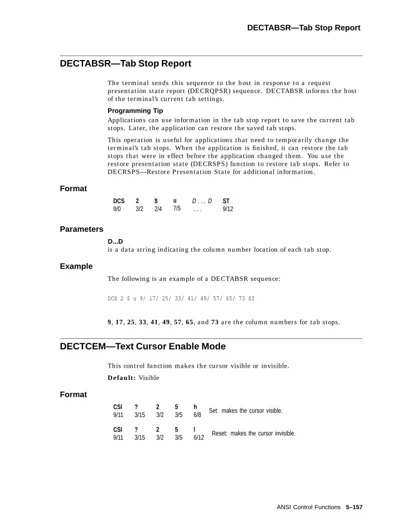
DECTABSR—Tab Stop Report
DECTABSR—Tab Stop Report
The terminal sends this sequence to the host in response to a requestpresentation state report (DECRQPSR) sequence. DECTABSR informs the hostof the terminal’s current tab settings.
Programming TipApplications can use information in the tab stop report to save the current tabstops. Later, the application can restore the saved tab stops.
This operation is useful for applications that need to temporarily change theterminal’s tab stops. When the application is finished, it can restore the tabstops that were in effect before the application changed them. You use therestore presentation state (DECRSPS) function to restore tab stops. Refer toDECRSPS—Restore Presentation State for additional information.
Format
DCS9/0
23/2
$2/4
u7/5
D . . . D. . .
ST9/12
Parameters
D...Dis a data string indicating the column number location of each tab stop.
Example
The following is an example of a DECTABSR sequence:
DCS 2 $ u 9/ 17/ 25/ 33/ 41/ 49/ 57/ 65/ 73 ST
9, 17, 25, 33, 41, 49, 57, 65, and 73 are the column numbers for tab stops.
DECTCEM—Text Cursor Enable Mode
This control function makes the cursor visible or invisible.
Default: Visible
Format
CSI9/11
?3/15
23/2
53/5
h6/8
Set: makes the cursor visible.
CSI9/11
?3/15
23/2
53/5
l6/12
Reset: makes the cursor invisible.
ANSI Control Functions 5–157

DECTID—Select Terminal ID
DECTID—Select Terminal ID
Select a terminal ID.
Format
CSI9/11
Ps3n
,2/12
q7/1
Parameters
Psdenotes the ID type.
Ps ID Type
0 VT1001 VT1012 VT1025 VT2207 VT3209 VT42010 VT520
Description
This sequence selects the Primary DA Response ("Terminal ID") transmitted bythe terminal in either VT100 or VT500 mode. DECTID has no effect when theterminal is in VT52 mode.
The VT520 supports the following DA1 responses:
VT100 ID ESC [ ? 1; 2 cVT101 ID ESC [ ? 1; 0 cVT102 ID ESC [ ? 6 cVT220 ID (N.A.) CSI ? 62; 1; 2; 7; 8 cVT220 ID (Intnl) CSI ? 62; 1; 2; 7; 8; 9 cVT320 ID (N.A.) CSI ? 63; 1; 2; 7; 8 cVT320 ID (Intnl) CSI ? 63; 1; 2; 7; 8; 9 cVT420 ID (N.A.) CSI ? 64; 1; 2; 7; 8; 9; 15; 18; 21 cVT420 ID (Intnl) CSI ? 64; 1; 2; 7; 8; 9; 15; 18; 21 cVT520 ID Reference function DA1
The default ID is "VT520."
5–158 ANSI Control Functions

DECTME—Terminal Mode Emulation
DECTME—Terminal Mode Emulation
Select a terminal emulation mode.
Format
CSI9/11
Ps3/n
SP2/0
~7/17
Parameters
PsThe Ps parameter selects the terminal emulation mode as follows:
Table 5–7 Terminal Emulation Modes
Ps Terminal Mode
1 VT520 (VT Level 5)2 VT1003 VT524 VT PCTerm5 WYSE 60/1606 WYSE PCTerm7 WYSE 50/50+8 WYSE 150/1209 TVI 95010 TVI 92511 TVI 910+12 ADDS A213 SCO Console14 WYSE 325
Description
This sequence allows you to select the terminal emulation mode. After any modechange is made, a soft reset is performed.
The VT520 is functionally equivalent to the architectural level 5 terminal. VTLevel 5 provides level 2, 3, 4, and 5 compatibility. compatibility.
ANSI Control Functions 5–159

DECTME—Terminal Mode Emulation
Notes on DECTME
• Printer operations are not affected or halted by a change in mode.
• A soft reset is always performed as a result of a mode change between VTmodes.
Exception: Entering VT52 mode using DECANM does not cause a soft resetfrom VT100 mode, but does cause a soft reset from VT500 Mode.
• DECANM and DECSCL can also change the VT operating modes.
DECTME can be reported using DECRPSS from the VT modes. All WYSEemulations report like the WYSE 325.
DECTSR—Terminal State Report—Terminal to Host
Requests and reports the state of the terminal.
Format
CSI9/11
PsPs
$2/4
u7/5
Parameters
Psindicates the type of report the host requests from the terminal.
Ps Report Requested
0 ornone
Ignored. No report sent.
1 Terminal state report (DECTSR)
ResponseDCS 1 $ s D . . . D STD . . . DSee Device Attributes (DA1, DA2, DA3).
Description
DECRQTSR and DECTSR requests and reports the state of the terminal.
5–160 ANSI Control Functions
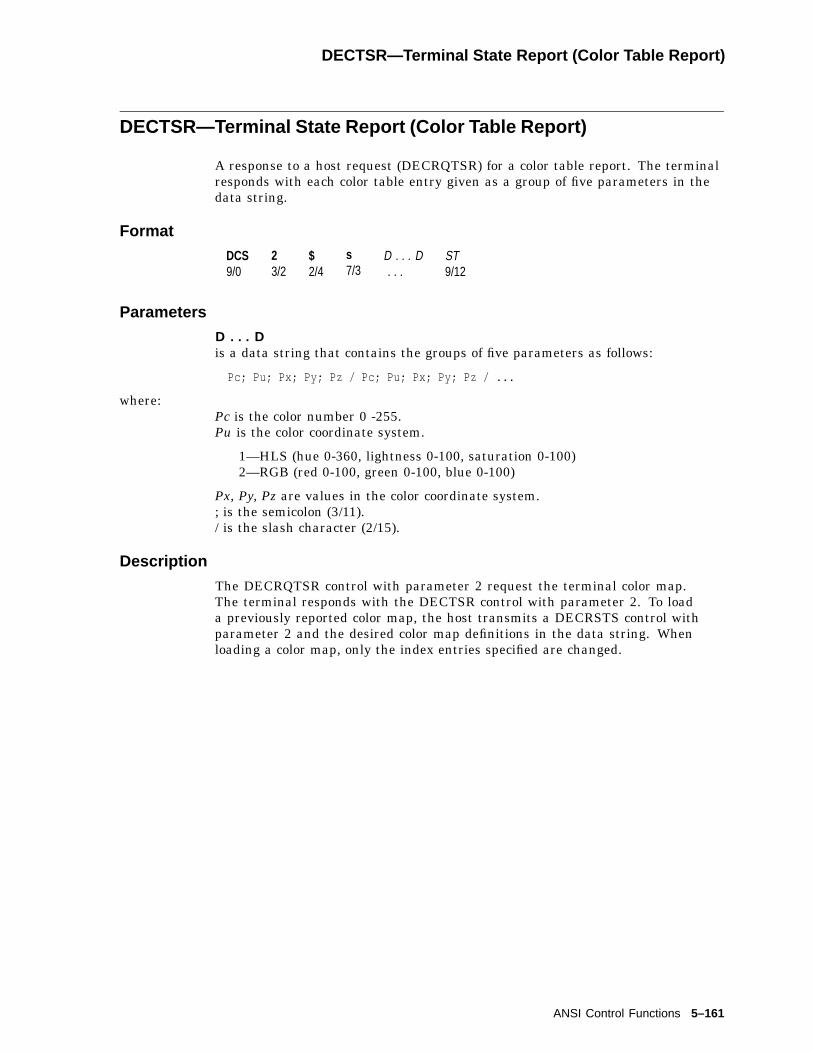
DECTSR—Terminal State Report (Color Table Report)
DECTSR—Terminal State Report (Color Table Report)
A response to a host request (DECRQTSR) for a color table report. The terminalresponds with each color table entry given as a group of five parameters in thedata string.
Format
DCS9/0
23/2
$2/4
s7/3
D . . . D. . .
ST9/12
Parameters
D . . . Dis a data string that contains the groups of five parameters as follows:
Pc; Pu; Px; Py; Pz / Pc; Pu; Px; Py; Pz / ...
where:Pc is the color number 0 -255.Pu is the color coordinate system.
1—HLS (hue 0-360, lightness 0-100, saturation 0-100)2—RGB (red 0-100, green 0-100, blue 0-100)
Px, Py, Pz are values in the color coordinate system.; is the semicolon (3/11)./ is the slash character (2/15).
Description
The DECRQTSR control with parameter 2 request the terminal color map.The terminal responds with the DECTSR control with parameter 2. To loada previously reported color map, the host transmits a DECRSTS control withparameter 2 and the desired color map definitions in the data string. Whenloading a color map, only the index entries specified are changed.
ANSI Control Functions 5–161

DECTST—Invoke Confidence Test
DECTST—Invoke Confidence Test
Select tests to be performed.
Format
CSI9/11
43/4
;3/11
Ps3/n
. . .
. . .;3/11
Ps3/n
y7/9
Parameters
Psis the parameter indicating a test to be done.
Ps Test
0 "All Tests" (1,2,3,6)1 Power-Up Self Test2 RS-232 Port Data Loopback Test3 Printer Port Loopback Test4 Speed Select and Speed Indicator Test5 Reserved - No action6 RS-232 Port Modem Control Line Loopback Test7 DEC-423 Port Loopback Test8 Parallel Port Loopback Test9 Repeat (Loop On) Other Tests In Parameter String
Description
After the first parameter, "4", the parameters each select one test. Severaltests may be invoked at once by chaining the parameters together separated bysemicolons. The tests are not necessarily executed in the order in which they areentered in the parameter string.
‘‘ESC 8’’ invokes the Screen Alignment test for the VT520. Additionally, afterexecuting the power-up selftest, the terminal displays either the diagnosticmessages in the upper left corner of the screen or the "VT520 OK" message in thecenter of the screen and within a box. Upon receipt of any character except XONor if the user types a keystroke, the screen is cleared. If the terminal is in localmode, then characters from the host are ignored and the message remains visibleeven if characters are received from the host. DECTST causes a disconnect;therefore, it should not be used in conjunction with a modem.
5–162 ANSI Control Functions
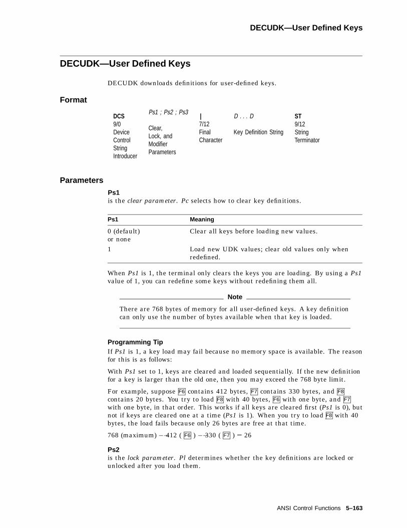
DECUDK—User Defined Keys
DECUDK—User Defined Keys
DECUDK downloads definitions for user-defined keys.
Format
DCS9/0DeviceControlStringIntroducer
Ps1 ; Ps2 ; Ps3
Clear,Lock, andModifierParameters
|7/12FinalCharacter
D . . . D
Key Definition String
ST9/12StringTerminator
Parameters
Ps1is the clear parameter. Pc selects how to clear key definitions.
Ps1 Meaning
0 (default)or none
Clear all keys before loading new values.
1 Load new UDK values; clear old values only whenredefined.
When Ps1 is 1, the terminal only clears the keys you are loading. By using a Ps1value of 1, you can redefine some keys without redefining them all.
Note
There are 768 bytes of memory for all user-defined keys. A key definitioncan only use the number of bytes available when that key is loaded.
Programming TipIf Ps1 is 1, a key load may fail because no memory space is available. The reasonfor this is as follows:
With Ps1 set to 1, keys are cleared and loaded sequentially. If the new definitionfor a key is larger than the old one, then you may exceed the 768 byte limit.
For example, suppose F6 contains 412 bytes, F7 contains 330 bytes, and F8
contains 20 bytes. You try to load F8 with 40 bytes, F6 with one byte, and F7
with one byte, in that order. This works if all keys are cleared first (Ps1 is 0), butnot if keys are cleared one at a time (Ps1 is 1). When you try to load F8 with 40bytes, the load fails because only 26 bytes are free at that time.
768 (maximum) � 412 ( F6 ) � 330 ( F7 ) = 26
Ps2is the lock parameter. Pl determines whether the key definitions are locked orunlocked after you load them.
ANSI Control Functions 5–163

DECUDK—User Defined Keys
Ps2 Action
0 or none Lock the keys. If you want to load new values into the keys, thenyou must unlock the keys by using Set-Up.
1 Do not lock the keys against future redefinition.
If Ps2 is 1 and the keys are already locked, then nothing happens.
The terminal uses a special lock to prevent or allow the programming of user-defined keys. You can turn on this lock from Set-Up or from the host (with aDECUDK device control string). The lock affects all programmable keys. Whenyou use the lock, you should follow these guidelines:
• Unlock the keys to define them.
The keys must be unlocked before you can define them. You can only unlockthe keys from set-up. If a key is locked and an application tries to redefinethe key with a DECUDK sequence, then the terminal ignores the sequence.
• Lock the keys to prevent redefinition.
You can lock the keys from Set-Up or from the host by sending a DECUDKsequence. New key definitions are locked by default.
Ps3is the modifier parameter. Ps3 designates whether the key is shifted or unshifted.
Ps3 Action
0, 2, or none Defines the shifted function key.1 Defines the unshifted function key.3 Defines the alternate unshifted function key.4 Defines the alternate shifted function key.
|is the final character. The vertical bar (7/12) identifies this control string as aDECUDK.
D . . . Dare the key definition strings. You include these strings between the finalcharacter ( | ) and the string terminator (ST). Each string consists of a keyselector number (Kyn) and a string parameter (Stn), separated by a slash (/)(2/15). A semicolon (;) (3/11) separates different strings.
• The key selector number (Kyn) indicates which key you are defining. Tables5–8 and 5–9 list the definable keys and their identifying values. Table 5–10compares the function keys on the VT keyboard to equivalent keys on the PCkeyboard.
5–164 ANSI Control Functions

DECUDK—User Defined Keys
Description
Table 5–8 VT Keyboards
Pm = 1 Pm = none, 0, or 2
Kyn Key Key
11 F1 Shift/F1
12 F2 Shift/F2
13 F3 Shift/F3
14 F4 Shift/F4
15 F5 Shift/F5
17 F6 Shift/F6
18 F7 Shift/F7
19 F8 Shift/F8
20 F9 Shift/F9
21 F10 Shift/F10
23 F11 Shift/F11
24 F12 Shift/F12
25 F13 Shift/F13
26 F14 Shift/F14
28 F15 Shift/F15
29 F16 Shift/F16
31 F17 Shift/F17
32 F18 Shift/F18
33 F19 Shift/F19
34 F20 Shift/F20
Note
Pm values of 3 and 4 are specific to the PC keyboard.They are ignored when you use a VT keyboard.
ANSI Control Functions 5–165

DECUDK—User Defined Keys
Table 5–9 PC Keyboards
Pm Value
Kyn 1 None, 0, or 2 3 4
11 F1 Shift/F1 Alt/F1 Alt/Shift/F1
12 F2 Shift/F2 Alt/F2 Alt/Shift/F2
13 F3 Shift/F3 Alt/F3 Alt/Shift/F3
14 F4 Shift/F4 Alt/F4 Alt/Shift/F4
15 F5 Shift/F5 Alt/F5 Alt/Shift/F5
17 F6 Shift/F6 Alt/F6 Alt/Shift/F6
18 F7 Shift/F7 Alt/F7 Alt/Shift/F7
19 F8 Shift/F8 Alt/F8 Alt/Shift/F8
20 F9 Shift/F9 Alt/F9 Alt/Shift/F9
21 F10 Shift/F10 Alt/F10 Alt/Shift/F10
23 F11 Shift/F11 Alt/F11 Alt/Shift/F11
24 F12 Shift/F12 Alt/F12 Alt/Shift/F12
25 Alt/F3 Alt/Shift/F3 – –26 Alt/F4 Alt/Shift/F4 – –28 Alt/F5 Alt/Shift/F5 – –29 Alt/F6 Alt/Shift/F6 – –31 Alt/F7 Alt/Shift/F7 – –32 Alt/F8 Alt/Shift/F8 – –33 Alt/F9 Alt/Shift/F9 – –34 Alt/F10 Alt/Shift/F10 – –35 Alt/F11 Alt/Shift/F11 – –36 Alt/F12 Alt/Shift/F12 – –
5–166 ANSI Control Functions
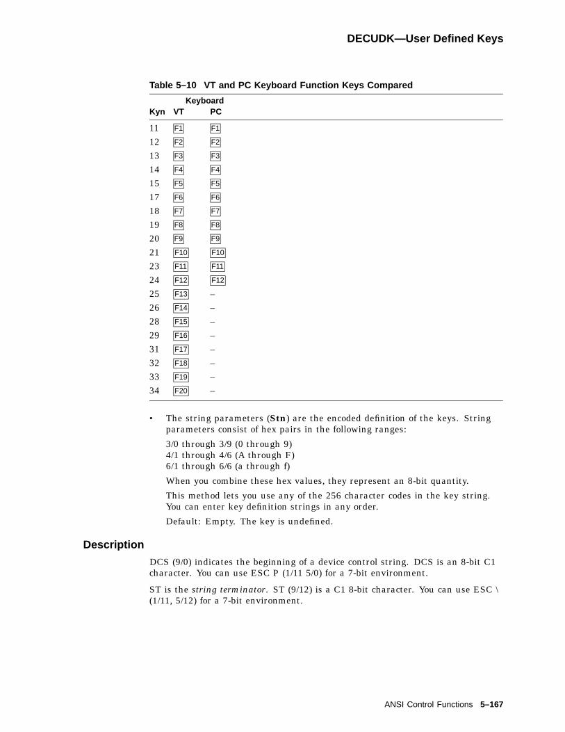
DECUDK—User Defined Keys
Table 5–10 VT and PC Keyboard Function Keys Compared
KeyboardKyn VT PC
11 F1 F1
12 F2 F2
13 F3 F3
14 F4 F4
15 F5 F5
17 F6 F6
18 F7 F7
19 F8 F8
20 F9 F9
21 F10 F10
23 F11 F11
24 F12 F12
25 F13 –26 F14 –28 F15 –29 F16 –31 F17 –32 F18 –33 F19 –34 F20 –
• The string parameters (Stn) are the encoded definition of the keys. Stringparameters consist of hex pairs in the following ranges:
3/0 through 3/9 (0 through 9)4/1 through 4/6 (A through F)6/1 through 6/6 (a through f)
When you combine these hex values, they represent an 8-bit quantity.
This method lets you use any of the 256 character codes in the key string.You can enter key definition strings in any order.
Default: Empty. The key is undefined.
Description
DCS (9/0) indicates the beginning of a device control string. DCS is an 8-bit C1character. You can use ESC P (1/11 5/0) for a 7-bit environment.
ST is the string terminator. ST (9/12) is a C1 8-bit character. You can use ESC \(1/11, 5/12) for a 7-bit environment.
ANSI Control Functions 5–167

DECUDK—User Defined Keys
General Guidelines When Loading UDKs
• Clear UDK memory space before loading new definitions.
Use a DECUDK string to clear keys without locking them. Then you can useanother DECUDK string to redefine the keys and lock them.
• If you redefine a key, then the old definition is lost. This clears space if thenew definition uses less bytes than the old one.
• There is only one way to unlock UDKs.
To unlock a UDK, use Set-Up.
• When you clear a UDK, the key definition is empty.
• An invalid hex pair in a DECUDK string stops a UDK sequence.
When a load sequence stops (error or other cause), the terminal saves keysalready loaded and sends the rest of DECUDK to the screen.
• You can disable the local function keys by redefining them with DECUDK.
• DECUDK works in all VT modes except VT52 mode.
Examples of DECUDK Device Control Strings
The following sequence clears unshifted UDKs:
DCS 0 ; 1 ; 1 | ST
The following sequence locks unshifted UDKs:
DCS 1 ; 0 ; 1 | ST
Suppose you want to define the unshifted F20 key to be ‘‘PRINT’’, without clearingor locking any other keys. The first part of your sequence would look like this:
DCS 1 ; 1 ; 1 | 3 4 /
34 is the code for the F20 key.
After the slash character (/) (2/15), you include the definition. The rest of thesequence after the slash character would look like this:
5 0 5 2 4 9 4 E 5 4 ST
The hex encoding for ‘‘PRINT’’ is as follows:
50 = P52 = R49 = I4E = N54 = T
The ST character (9/12) marks the end of the control string:
DCS 1 ; 1 ; 1 | 34 / 50 52 49 4E 54 ST
5–168 ANSI Control Functions

DECUS—Update Session
DECUS—Update Session
Controls how display memory is updated for this session when it is not active.
Default: Update when available
Format
CSI9/11
Ps,2/12
y7/9
Description
Update session according to the parameter Ps as follows:
Ps Update Session . . . Description
1 Only when active Prevents the session from beingupdated until it is explicitly madeactive by the user or the host.
2 When available Allows the session to be updated whenthe terminal is not otherwise busy withthe active session.
3 At regular intervals Ensures session will continue to beupdated even when not active.
DECUS can be reported using DECRPSS.
ANSI Control Functions 5–169

DECVCCM—Vertical Cursor-Coupling Mode
DECVCCM—Vertical Cursor-Coupling Mode
This control function determines whether the user window pans with the cursorwhen the cursor moves past the top or bottom border of the user window.DECVCCM is only useful when the height of the current user window is smallerthan the page. The cursor must stay on the current page.
Default: Coupled
Format
CSI9/11
?3/15
63/6
13/1
h6/8
Set: couples the cursor to the display.
CSI9/11
?3/15
63/6
13/1
l6/12
Reset: uncouples the cursor.
Description
When DECVCCM is set, the cursor is coupled to the display for verticalmovement. When the cursor moves past the top or bottom border of the userwindow, the window pans to keep the cursor in view.
If the cursor moves past the top of the display, the user window pans up. Newlines appear at the top of the screen, while lines at the bottom move out of view.
When DECVCCM is reset, the cursor is uncoupled from the display. If the cursormoves past the top or bottom border of the user window, the cursor disappears.
DECXCPR—Extended Cursor Position Report
The host asks the terminal for the current cursor position, including the currentpage number.
Format
CSI9/11
?3/15
63/16
n6/14
Response
CSI Pl ; Pc ; Pp R
Parameters
Pl; Pc; PpThe terminal indicates that the cursor is currently at line Pl, column Pc, on pagePp.
5–170 ANSI Control Functions

DECXRLM—Transmit Rate Limiting
DECXRLM—Transmit Rate Limiting
Applications can control the transmit rate limiting feature through theDECXRLM control function.
Default: Unlimited
Format
CSI9/11
?3/15
73/7
33/3
h6/8
Set: limited transmit rate.
CSI9/11
?3/15
73/7
33/3
l6/12
Reset: unlimited transmit rate.
Modem Connection and DisconnectionsWhen the terminal makes a connection to the host system through a modem,the terminal performs the following operations to ensure it is ready to send andreceive.
• Unlocks the keyboard (if it was locked).
• Clears any transmission in progress.
• Clears the keyboard buffer and all message buffers.
• Clears the input buffer.
• Clears XOFF sent and XOFF received.
Any of the following conditions will disconnect the connection to the host systemin VT mode:
• You press Shift F5 ( Shift Break ).
• You use the Recall or Default fields in the Set-Up Directory.
• You change the host port you are using (from the RS-232 port to the DEC-423port, or from the DEC-423 port to the RS-232 port).
• The terminal loses the data set read (DSR) signal.
• The terminal loses the received line signal detect (RLSD) signal for a periodof time you defined in set-up. See the disconnect delay feature in theCommunications Set-Up screen.
• The terminal does not receive an RLSD signal within 30 seconds after DSR.
• The terminal receives a self-test command from the host system.
The usual way to disconnect communications is to type Shift F5 ( Shift Break ). Thehost system’s response to the disconnect signal depends on the system and thesoftware.
Terminal-to-Printer Data Flow ControlThe terminal sends only data characters to the printer. The terminal does notsend XON and XOFF characters. The terminal recognizes only XON and XOFFcharacters from the printer. Any other characters from the printer are ignored.
When the terminal receives XOFF from the printer, the terminal stops sendingdata. The terminal starts sending data again when it receives an XON, or whena clear comm operation is performed.
ANSI Control Functions 5–171
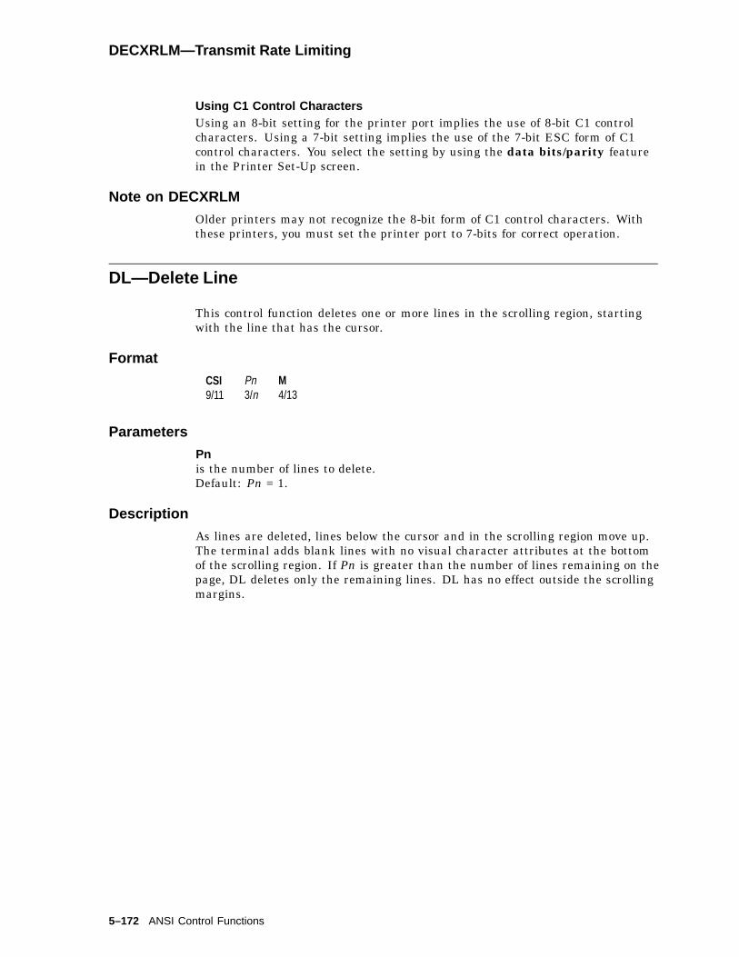
DECXRLM—Transmit Rate Limiting
Using C1 Control CharactersUsing an 8-bit setting for the printer port implies the use of 8-bit C1 controlcharacters. Using a 7-bit setting implies the use of the 7-bit ESC form of C1control characters. You select the setting by using the data bits/parity featurein the Printer Set-Up screen.
Note on DECXRLM
Older printers may not recognize the 8-bit form of C1 control characters. Withthese printers, you must set the printer port to 7-bits for correct operation.
DL—Delete Line
This control function deletes one or more lines in the scrolling region, startingwith the line that has the cursor.
Format
CSI9/11
Pn3/n
M4/13
Parameters
Pnis the number of lines to delete.Default: Pn = 1.
Description
As lines are deleted, lines below the cursor and in the scrolling region move up.The terminal adds blank lines with no visual character attributes at the bottomof the scrolling region. If Pn is greater than the number of lines remaining on thepage, DL deletes only the remaining lines. DL has no effect outside the scrollingmargins.
5–172 ANSI Control Functions

DSR—Device Status Reports
DSR—Device Status Reports
The host computer and terminal exchange DSR sequences to provide the hostwith the operating status of the following features:
Operating statusKeyboard status - languageCursor position reportCursor position with pagePrinter port
User-defined keysMacro space reportMemory checksumData integrity report-
DSR requests and reports follow one of two formats, ANSI standard or DECprivate. The format for each is as follows:
Format
CSI9/11
Ps3/?
n6/14 ANSI standard
CSI9/11
?3/15
Ps3/?
n6/14 DEC private
Parameters
Psindicates the type of DSR requested. See the following individual DSR reports forspecific parameters within each report.
Description
There is a different DSR request for each feature. The following sections describethe possible DSR reports. If the terminal is in printer controller mode, thenthe printer receives the DSR request. The printer can respond through thebidirectional printer port.
DSR—Cursor Position Report (CPR)
The host asks the terminal for a cursor position report.
FormatExchange Sequence Meaning
Request(Host to terminal)
CSI 6 n The host asks for a cursor positionreport (CPR).
CPR response(Terminal to host)
CSI Pl; Pc R The terminal indicates that the cursoris currently at line Pl, column Pc.
ANSI Control Functions 5–173
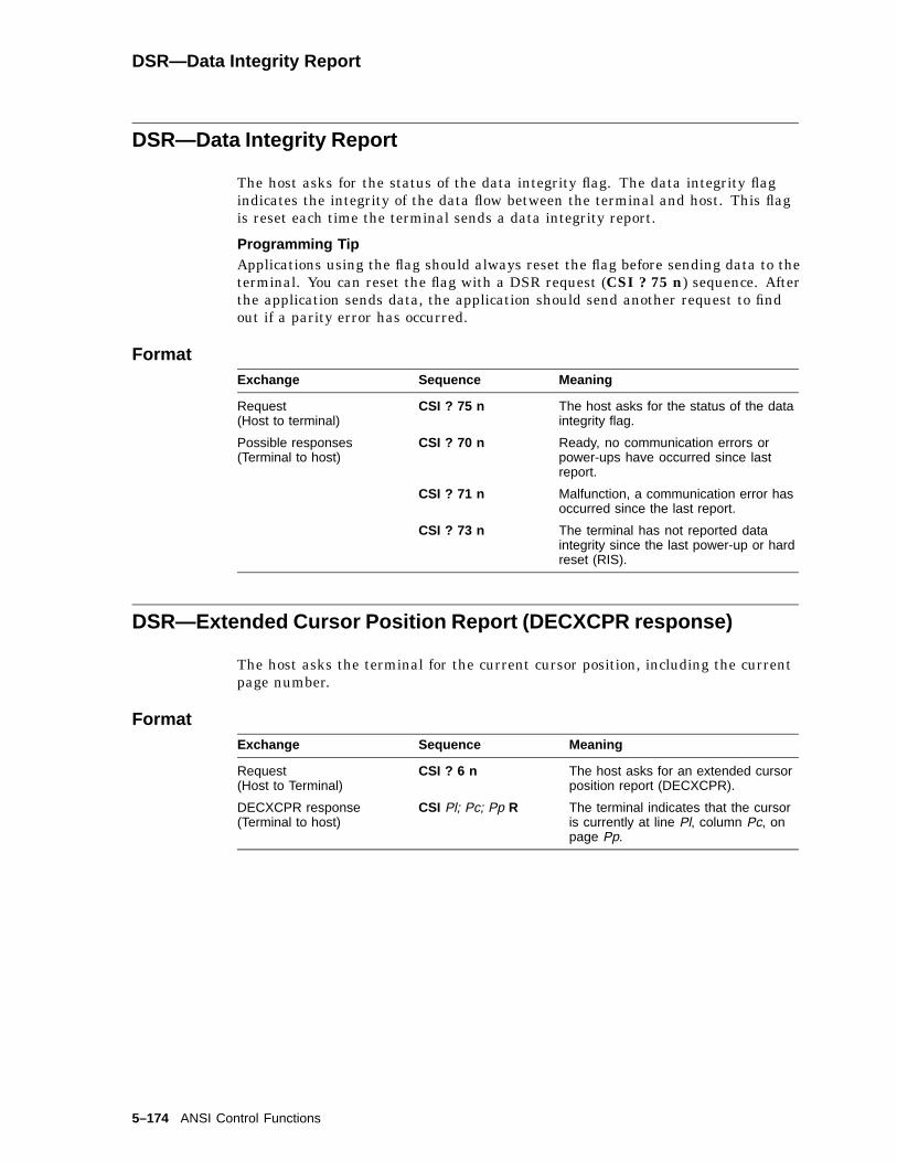
DSR—Data Integrity Report
DSR—Data Integrity Report
The host asks for the status of the data integrity flag. The data integrity flagindicates the integrity of the data flow between the terminal and host. This flagis reset each time the terminal sends a data integrity report.
Programming TipApplications using the flag should always reset the flag before sending data to theterminal. You can reset the flag with a DSR request (CSI ? 75 n) sequence. Afterthe application sends data, the application should send another request to findout if a parity error has occurred.
FormatExchange Sequence Meaning
Request(Host to terminal)
CSI ? 75 n The host asks for the status of the dataintegrity flag.
Possible responses(Terminal to host)
CSI ? 70 n Ready, no communication errors orpower-ups have occurred since lastreport.
CSI ? 71 n Malfunction, a communication error hasoccurred since the last report.
CSI ? 73 n The terminal has not reported dataintegrity since the last power-up or hardreset (RIS).
DSR—Extended Cursor Position Report (DECXCPR response)
The host asks the terminal for the current cursor position, including the currentpage number.
FormatExchange Sequence Meaning
Request(Host to Terminal)
CSI ? 6 n The host asks for an extended cursorposition report (DECXCPR).
DECXCPR response(Terminal to host)
CSI Pl; Pc; Pp R The terminal indicates that the cursoris currently at line Pl, column Pc, onpage Pp.
5–174 ANSI Control Functions
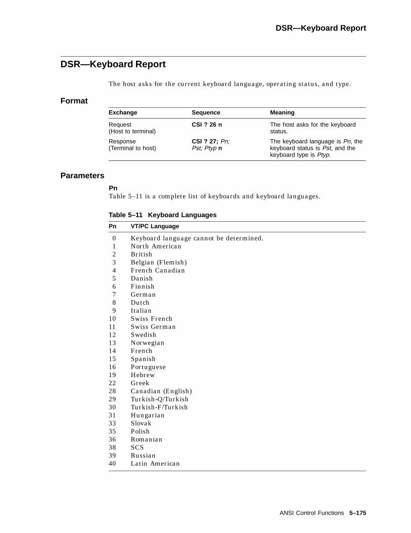
DSR—Keyboard Report
DSR—Keyboard Report
The host asks for the current keyboard language, operating status, and type.
FormatExchange Sequence Meaning
Request(Host to terminal)
CSI ? 26 n The host asks for the keyboardstatus.
Response(Terminal to host)
CSI ? 27; Pn;Pst; Ptyp n
The keyboard language is Pn, thekeyboard status is Pst, and thekeyboard type is Ptyp.
Parameters
PnTable 5–11 is a complete list of keyboards and keyboard languages.
Table 5–11 Keyboard Languages
Pn VT/PC Language
0 Keyboard language cannot be determined.1 North American2 British3 Belgian (Flemish)4 French Canadian5 Danish6 Finnish7 German8 Dutch9 Italian
10 Swiss French11 Swiss German12 Swedish13 Norwegian14 French15 Spanish16 Portuguese19 Hebrew22 Greek28 Canadian (English)29 Turkish-Q/Turkish30 Turkish-F/Turkish31 Hungarian33 Slovak35 Polish36 Romanian38 SCS39 Russian40 Latin American
ANSI Control Functions 5–175

DSR—Keyboard Report
Pstindicates the keyboard status.
Pst Keyboard Status‡
0 Keyboard Ready The terminal sends typed characters to the currentsession.
3 No Keyboard The terminal does not detect the keyboard.8 Keyboard Busy The other session is currently using the keyboard.
‡The terminal only sends Pst in VT level 4 or 5 mode.
Ptypindicates the keyboard type.
Ptyp Keyboard Type
4 LK4115 PCXAL
DSR—Macro Space Report
The host asks for the available macro space in the form of a macro space report(DECMSR).
FormatExchange Sequence Meaning
Request(Host to terminal)
CSI ? 62 n The host asks for a macro space report(DECMSR).
DECMSR response(Terminal to host)
CSI Pn * { The terminal indicates the number ofbytes available for macro definitions.
Parameters
PnPn =
number of bytes16 rounded down:
5–176 ANSI Control Functions

DSR—Memory Checksum Report (DECCKSR)
DSR—Memory Checksum Report (DECCKSR)
The host asks for a memory checksum report of current text macro definitions.
Programming TipEnter your macro definitions, then request and save a memory checksum. Later,you can request another checksum and see if it has changed.
FormatExchange Sequence Meaning
Request(Host to terminal)
CSI ? 63; Pid n The host asks for a memory checksumreport of current text macro definitions(DECCKSR).
Pid is an optional numeric parameterthat provides a label to identify theparticular checksum request. Thechecksum report returns the label.This label lets you differentiatebetween multiple checksum reports.
DECCKSR response(Terminal to host)
DCS Pid ! ~ D..D ST Pid is a label indicating which DSRrequest the report is for.
D..D is the data string consisting offour hexadecimal digits indicatingthe checksum. The digits can be inthe range of 3/0 through 3/9 and 4/0through 4/6.
DSR—Operating Status Report
The host requests the terminal’s operating status.
FormatExchange Sequence Meaning
Request(Host to terminal)
CSI 5 n The host requests the terminal’s operatingstatus. The host asks if the terminal is ingood operating condition.
Responses(Terminal to host)
CSI 0 n The terminal indicates that it is in goodoperating condition.
or
CSI 3 n The terminal indicates that it has amalfunction.
ANSI Control Functions 5–177
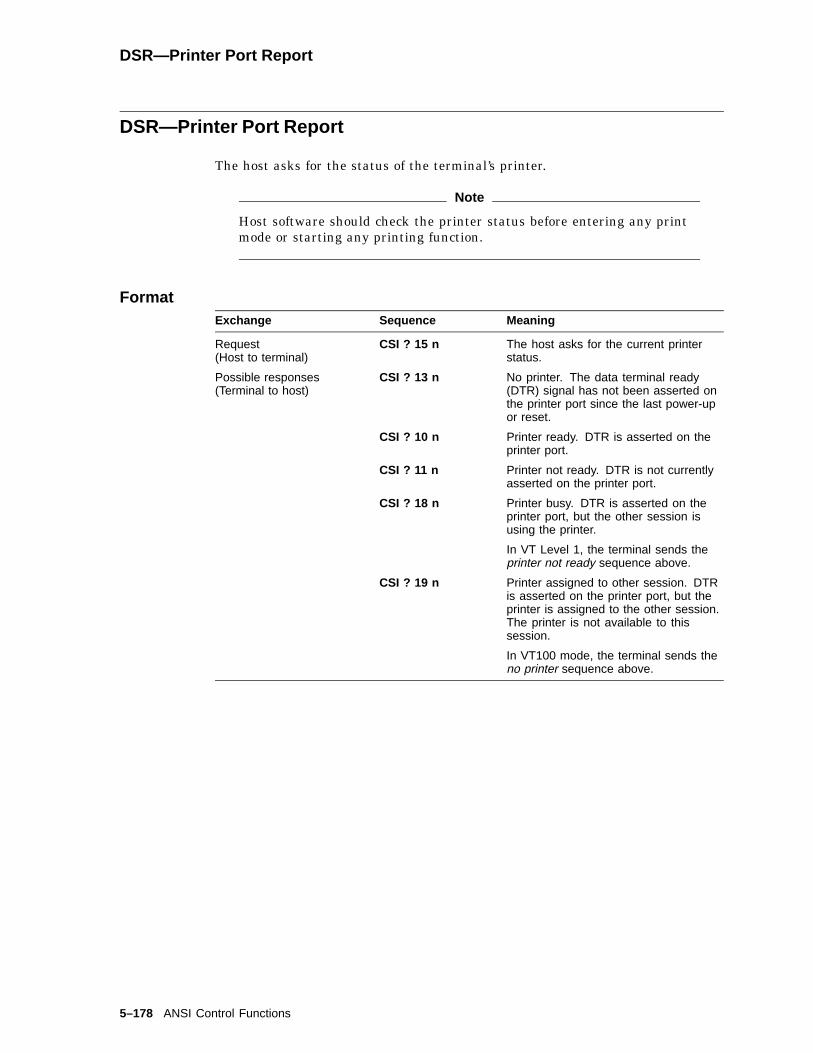
DSR—Printer Port Report
DSR—Printer Port Report
The host asks for the status of the terminal’s printer.
Note
Host software should check the printer status before entering any printmode or starting any printing function.
FormatExchange Sequence Meaning
Request(Host to terminal)
CSI ? 15 n The host asks for the current printerstatus.
Possible responses(Terminal to host)
CSI ? 13 n No printer. The data terminal ready(DTR) signal has not been asserted onthe printer port since the last power-upor reset.
CSI ? 10 n Printer ready. DTR is asserted on theprinter port.
CSI ? 11 n Printer not ready. DTR is not currentlyasserted on the printer port.
CSI ? 18 n Printer busy. DTR is asserted on theprinter port, but the other session isusing the printer.
In VT Level 1, the terminal sends theprinter not ready sequence above.
CSI ? 19 n Printer assigned to other session. DTRis asserted on the printer port, but theprinter is assigned to the other session.The printer is not available to thissession.
In VT100 mode, the terminal sends theno printer sequence above.
5–178 ANSI Control Functions
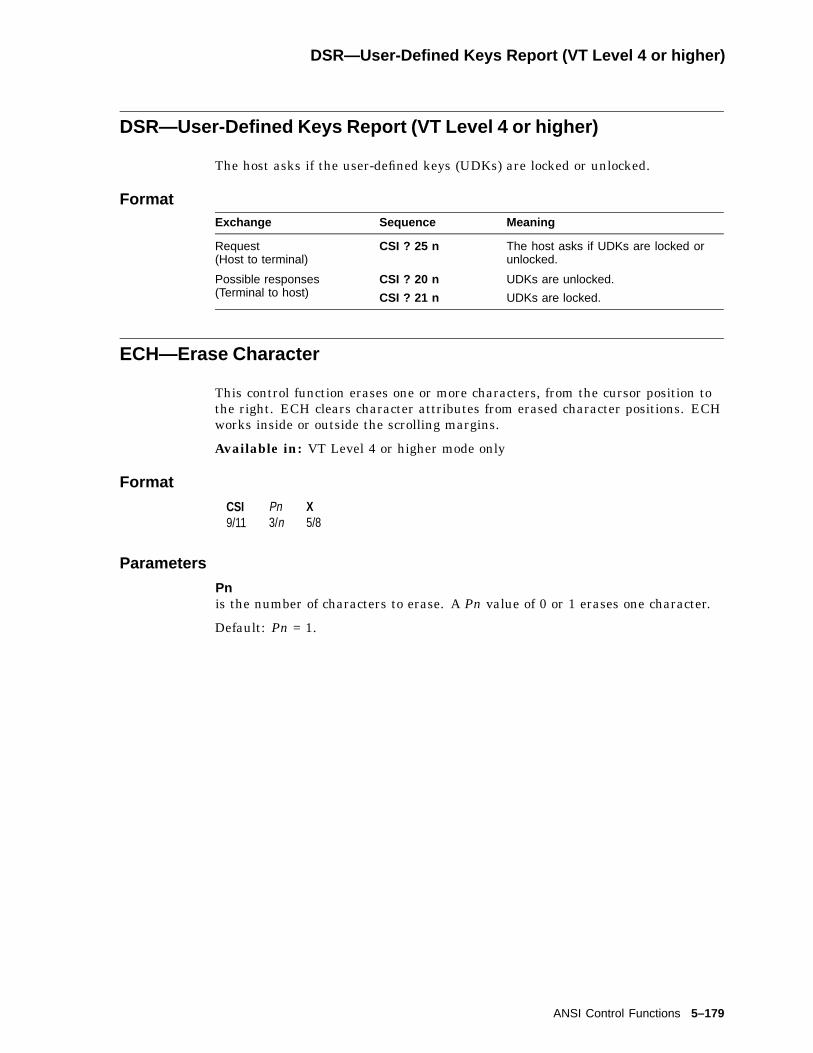
DSR—User-Defined Keys Report (VT Level 4 or higher)
DSR—User-Defined Keys Report (VT Level 4 or higher)
The host asks if the user-defined keys (UDKs) are locked or unlocked.
FormatExchange Sequence Meaning
Request(Host to terminal)
CSI ? 25 n The host asks if UDKs are locked orunlocked.
Possible responses(Terminal to host)
CSI ? 20 n
CSI ? 21 n
UDKs are unlocked.
UDKs are locked.
ECH—Erase Character
This control function erases one or more characters, from the cursor position tothe right. ECH clears character attributes from erased character positions. ECHworks inside or outside the scrolling margins.
Available in: VT Level 4 or higher mode only
Format
CSI9/11
Pn3/n
X5/8
Parameters
Pnis the number of characters to erase. A Pn value of 0 or 1 erases one character.
Default: Pn = 1.
ANSI Control Functions 5–179
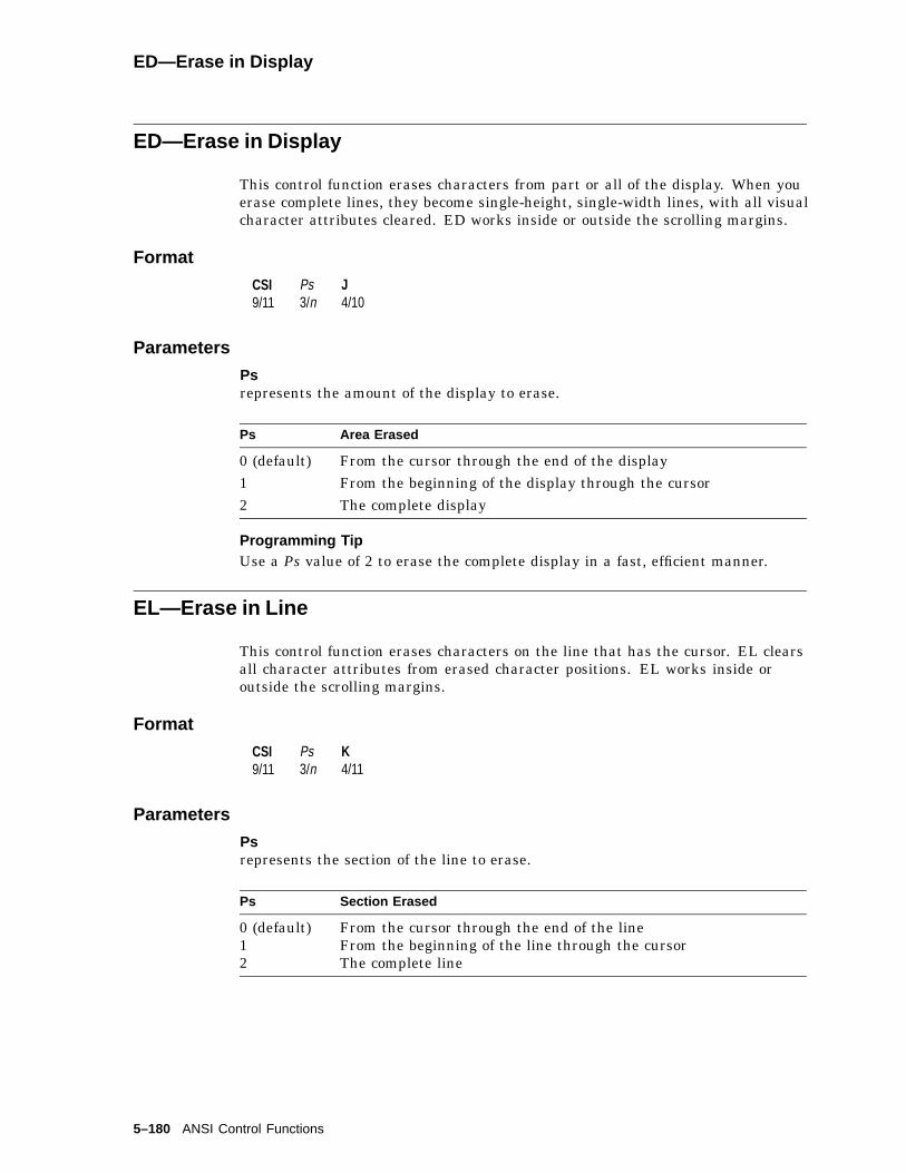
ED—Erase in Display
ED—Erase in Display
This control function erases characters from part or all of the display. When youerase complete lines, they become single-height, single-width lines, with all visualcharacter attributes cleared. ED works inside or outside the scrolling margins.
Format
CSI9/11
Ps3/n
J4/10
Parameters
Psrepresents the amount of the display to erase.
Ps Area Erased
0 (default) From the cursor through the end of the display1 From the beginning of the display through the cursor2 The complete display
Programming TipUse a Ps value of 2 to erase the complete display in a fast, efficient manner.
EL—Erase in Line
This control function erases characters on the line that has the cursor. EL clearsall character attributes from erased character positions. EL works inside oroutside the scrolling margins.
Format
CSI9/11
Ps3/n
K4/11
Parameters
Psrepresents the section of the line to erase.
Ps Section Erased
0 (default) From the cursor through the end of the line1 From the beginning of the line through the cursor2 The complete line
5–180 ANSI Control Functions

HPA—Horizontal Position Absolute
HPA—Horizontal Position Absolute
Move the active position to the n-th horizontal position of the active line.
Format
CSI9/11
Pn3/n
‘6/0
Parameters
Pnindicates horizontal position.
Description
HPA causes the active position to be moved to the n-th horizontal position ofthe active line. If an attempt is made to move the active position past the lastposition on the line, then the active position stops at the last position on the line.
HPR—Horizontal Position Relative
Move the active position to the n-th column following the current horizontalposition of the active line.
Format
CSI9/11
Pn3/n
a6/1
Parameters
Pnindicates horizontal position.
Description
HPR causes the active position to be moved to the n-th following horizontalposition of the active line. If an attempt is made to move the active position pastthe last position on the line, then the active position stops at the last position onthe line.
ANSI Control Functions 5–181

HT—Horizontal Tab
HT—Horizontal Tab
HT moves the active position forward in the display to the next horizontal tabstop in the active line.
FormatHT0/9
Description
• If the active position does not reach a tab stop before reaching the rightmargin of the active line within the scroll area, then the terminal will set theactive position to the right margin of the active line.
• If the active column is beyond the right margin or the active line is outsidethe scroll area because of absolute cursor positioning, then the active positionwill move to the next tab stop or the last column of the active line, whichevercomes first.
HTS—Horizontal Tab Set
HTS sets a horizontal tab stop at the column position indicated by the value ofthe active column when the terminal receives an HTS.
You can use either one of the following formats:
Format
HTS8/8
or ESC1/11
H4/8
Description
Executing an HTS does not effect the other horizontal tab stop settings.
5–182 ANSI Control Functions
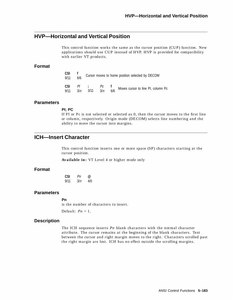
HVP—Horizontal and Vertical Position
HVP—Horizontal and Vertical Position
This control function works the same as the cursor position (CUP) function. Newapplications should use CUP instead of HVP. HVP is provided for compatibilitywith earlier VT products.
Format
CSI9/11
f6/6
Cursor moves to home position selected by DECOM
CSI9/11
Pl3/n
;3/11
Pc3/n
f6/6
Moves cursor to line PI, column Pc
Parameters
PI; PCIf PI or Pc is not selected or selected as 0, then the cursor moves to the first lineor column, respectively. Origin mode (DECOM) selects line numbering and theability to move the cursor into margins.
ICH—Insert Character
This control function inserts one or more space (SP) characters starting at thecursor position.
Available in: VT Level 4 or higher mode only
Format
CSI9/11
Pn3/n
@4/0
Parameters
Pnis the number of characters to insert.
Default: Pn = 1.
Description
The ICH sequence inserts Pn blank characters with the normal characterattribute. The cursor remains at the beginning of the blank characters. Textbetween the cursor and right margin moves to the right. Characters scrolled pastthe right margin are lost. ICH has no effect outside the scrolling margins.
ANSI Control Functions 5–183

IL—Insert Line
IL—Insert Line
This control function inserts one or more blank lines, starting at the cursor.
Format
CSI9/11
Pn3/n
L4/12
Parameters
Pnis the number of lines to insert.Default: Pn = 1.
Description
As lines are inserted, lines below the cursor and in the scrolling region movedown. Lines scrolled off the page are lost. IL has no effect outside the pagemargins.
IND—Index
IND moves the cursor down one line in the same column. If the cursor is at thebottom margin, then the screen performs a scroll-up.
Format
ESC1/11
D4/4
5–184 ANSI Control Functions

IRM—Insert/Replace Mode
IRM—Insert/Replace Mode
This control function selects how the terminal adds characters to page memory.The terminal always adds new characters at the cursor position.
Default: Replace.
Format
CSI9/11
43/4
h6/8
Set: insert mode.
CSI9/11
43/4
l6/12
Reset: replace mode.
Description
If IRM mode is set, then new characters move characters in page memory to theright. Characters moved past the page’s right border are lost.
If IRM mode is reset, then new characters replace the character at the cursorposition.
KAM—Keyboard Action Mode
This control function locks or unlocks the keyboard.
Default: Unlocked
Format
CSI9/11
23/2
h6/8
Set: locks the keyboard.
CSI9/11
23/2
l6/12
Reset: unlocks the keyboard.
Description
If KAM is set, then the keyboard cannot send characters to the host. The Waitindicator appears on the keyboard indicator line at the bottom of the screen. Theterminal ignores all keystrokes that send characters to the host. KAM does notaffect the F3 (Set-Up) or F4 (Session) keys.
If KAM is reset, then the terminal unlocks the keyboard. The keyboard can sendcharacters to the host.
ANSI Control Functions 5–185

LNM—Line Feed/New Line Mode
LNM—Line Feed/New Line Mode
This control function selects the characters sent to the host when you press theReturn key. LNM also controls how the terminal interprets line feed (LF), formfeed (FF), and vertical tab (VT) characters.
Note
For compatibility with Digital’s software, you should keep LNM reset (linefeed).
Default: Line feed
Format
CSI9/11
23/2
03/0
h6/8
Set: new line.
CSI9/11
23/2
03/0
l6/12
Reset: line feed
Description
If LNM is set, then the cursor moves to the first column on the next line whenthe terminal receives an LF, FF, or VT character. When you press Return , theterminal sends both a carriage return (CR) and line feed (LF).
If LNM is reset, then the cursor moves to the current column on the next linewhen the terminal receives an LF, FF, or VT character. When you press Return ,the terminal sends only a carriage return (CR) character.
Note on LNM
When the auxiliary keypad is in keypad numeric mode (DECKPNM), the Enter
key sends the same characters as the Return key.
5–186 ANSI Control Functions
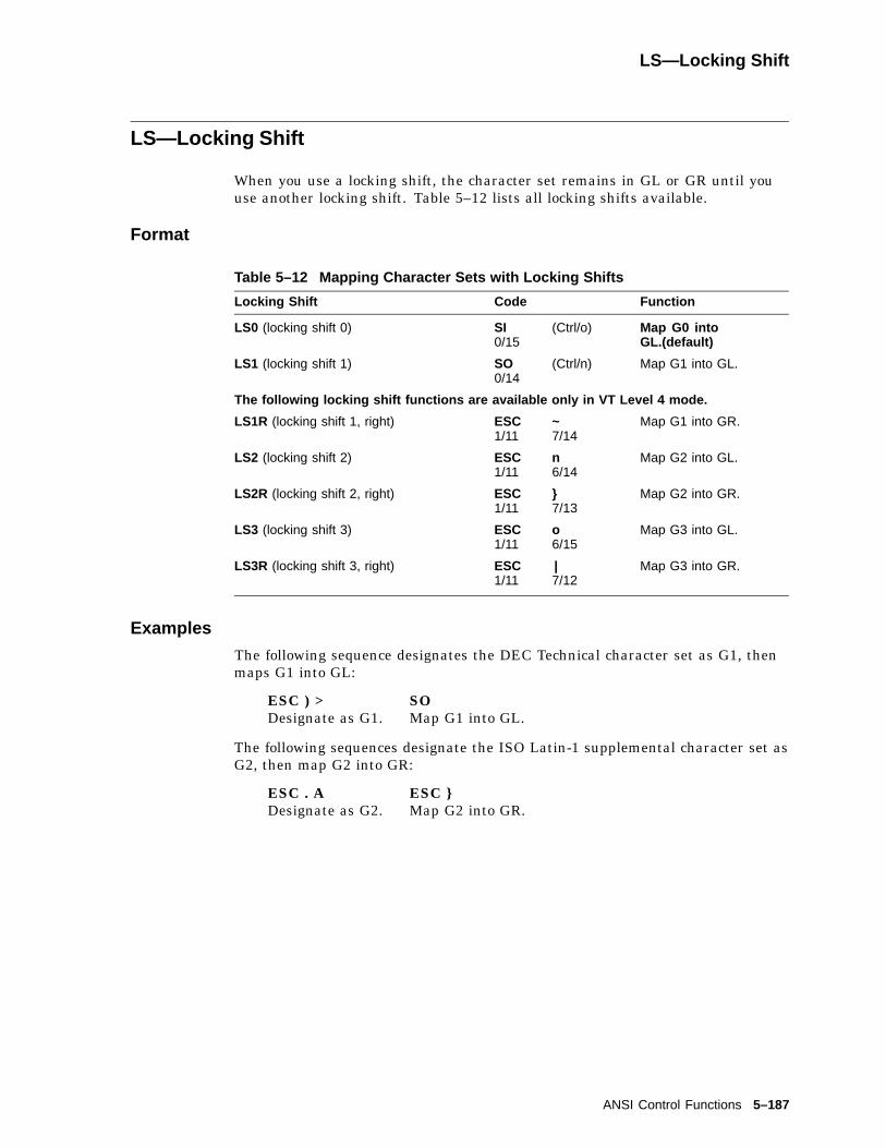
LS—Locking Shift
LS—Locking Shift
When you use a locking shift, the character set remains in GL or GR until youuse another locking shift. Table 5–12 lists all locking shifts available.
Format
Table 5–12 Mapping Character Sets with Locking Shifts
Locking Shift Code Function
LS0 (locking shift 0) SI0/15
(Ctrl/o) Map G0 intoGL.(default)
LS1 (locking shift 1) SO0/14
(Ctrl/n) Map G1 into GL.
The following locking shift functions are available only in VT Level 4 mode.
LS1R (locking shift 1, right) ESC1/11
~7/14
Map G1 into GR.
LS2 (locking shift 2) ESC1/11
n6/14
Map G2 into GL.
LS2R (locking shift 2, right) ESC1/11
}7/13
Map G2 into GR.
LS3 (locking shift 3) ESC1/11
o6/15
Map G3 into GL.
LS3R (locking shift 3, right) ESC1/11
|7/12
Map G3 into GR.
Examples
The following sequence designates the DEC Technical character set as G1, thenmaps G1 into GL:
ESC ) >Designate as G1.
SOMap G1 into GL.
The following sequences designate the ISO Latin-1 supplemental character set asG2, then map G2 into GR:
ESC . ADesignate as G2.
ESC }Map G2 into GR.
ANSI Control Functions 5–187
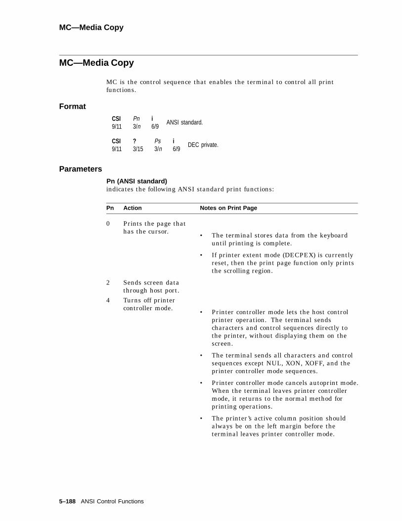
MC—Media Copy
MC—Media Copy
MC is the control sequence that enables the terminal to control all printfunctions.
Format
CSI9/11
Pn3/n
i6/9
ANSI standard.
CSI9/11
?3/15
Ps3/n
i6/9
DEC private.
Parameters
Pn (ANSI standard)indicates the following ANSI standard print functions:
Pn Action Notes on Print Page
0 Prints the page thathas the cursor. • The terminal stores data from the keyboard
until printing is complete.
• If printer extent mode (DECPEX) is currentlyreset, then the print page function only printsthe scrolling region.
2 Sends screen datathrough host port.
4 Turns off printercontroller mode. • Printer controller mode lets the host control
printer operation. The terminal sendscharacters and control sequences directly tothe printer, without displaying them on thescreen.
• The terminal sends all characters and controlsequences except NUL, XON, XOFF, and theprinter controller mode sequences.
• Printer controller mode cancels autoprint mode.When the terminal leaves printer controllermode, it returns to the normal method forprinting operations.
• The printer’s active column position shouldalways be on the left margin before theterminal leaves printer controller mode.
5–188 ANSI Control Functions
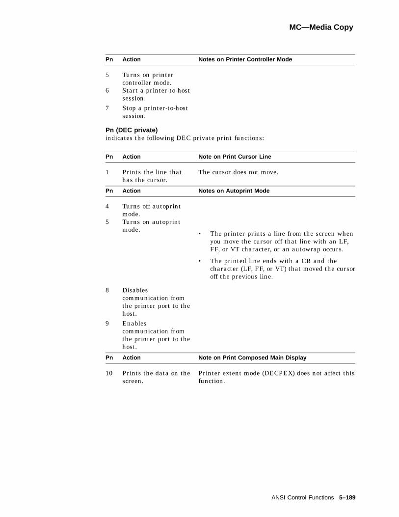
MC—Media Copy
Pn Action Notes on Printer Controller Mode
5 Turns on printercontroller mode.
6 Start a printer-to-hostsession.
7 Stop a printer-to-hostsession.
Pn (DEC private)indicates the following DEC private print functions:
Pn Action Note on Print Cursor Line
1 Prints the line thathas the cursor.
The cursor does not move.
Pn Action Notes on Autoprint Mode
4 Turns off autoprintmode.
5 Turns on autoprintmode. • The printer prints a line from the screen when
you move the cursor off that line with an LF,FF, or VT character, or an autowrap occurs.
• The printed line ends with a CR and thecharacter (LF, FF, or VT) that moved the cursoroff the previous line.
8 Disablescommunication fromthe printer port to thehost.
9 Enablescommunication fromthe printer port to thehost.
Pn Action Note on Print Composed Main Display
10 Prints the data on thescreen.
Printer extent mode (DECPEX) does not affect thisfunction.
ANSI Control Functions 5–189

MC—Media Copy
Pn Action Notes on Print All Pages
11 Prints all pages inpage memory. • If the current page format is 3 pages of 24 lines
each, the printer prints 3 pages of 24 lines.
• The terminal stores new data from thekeyboard until printing is complete.
• If print form feed mode (DECPFF) is set, thenthe terminal sends a form feed (FF) to theprinter after each page.
18 Lets the terminalaccept printercommands.
Description
Escape Sequence CSI 6 i and CSI 7 i are functionally equivalent to CSI ? 9 i andCSI ? 8 i. Also, CSI ? 9 i and CSI ? 8 i are media copy commands used in VTterminals to set/reset printer to host mode.
5–190 ANSI Control Functions

NEL—Next Line
NEL—Next Line
Moves cursor to first position on next line. If cursor is at bottom margin, thenscreen performs a scroll-up.
Format
ESC033
E105
NP—Next Page
This control function moves the cursor forward to the home position on one ofthe following pages in page memory. If there is only one page, then the terminalignores NP.
Default: Move to the next page.
Format
CSI9/11
Pn3/n
U5/5
Parameters
Pnindicates how many pages to move the cursor forward.
Default: Pn = 0.
If Pn is 0 or 1, then the cursor moves to the next page in page memory. If Pntries to move the cursor past the last page in memory, then the cursor stops atthe last page.
ANSI Control Functions 5–191
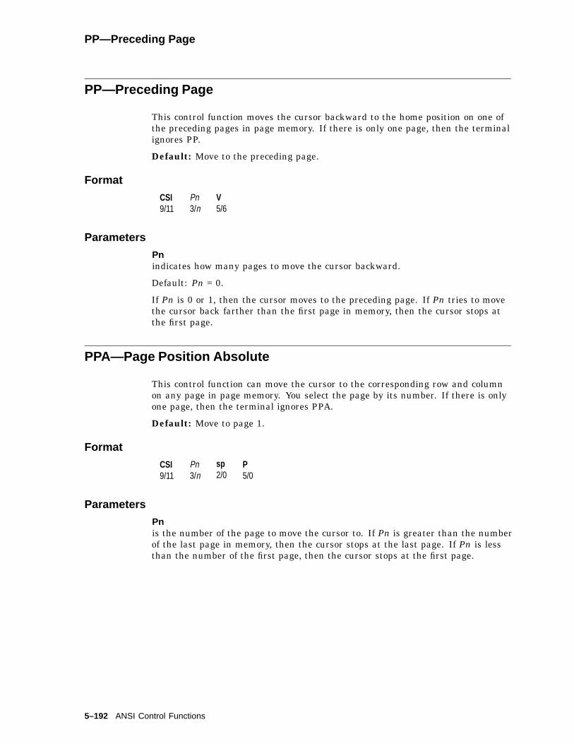
PP—Preceding Page
PP—Preceding Page
This control function moves the cursor backward to the home position on one ofthe preceding pages in page memory. If there is only one page, then the terminalignores PP.
Default: Move to the preceding page.
Format
CSI9/11
Pn3/n
V5/6
Parameters
Pnindicates how many pages to move the cursor backward.
Default: Pn = 0.
If Pn is 0 or 1, then the cursor moves to the preceding page. If Pn tries to movethe cursor back farther than the first page in memory, then the cursor stops atthe first page.
PPA—Page Position Absolute
This control function can move the cursor to the corresponding row and columnon any page in page memory. You select the page by its number. If there is onlyone page, then the terminal ignores PPA.
Default: Move to page 1.
Format
CSI9/11
Pn3/n
sp2/0
P5/0
Parameters
Pnis the number of the page to move the cursor to. If Pn is greater than the numberof the last page in memory, then the cursor stops at the last page. If Pn is lessthan the number of the first page, then the cursor stops at the first page.
5–192 ANSI Control Functions
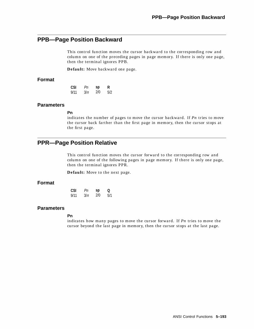
PPB—Page Position Backward
PPB—Page Position Backward
This control function moves the cursor backward to the corresponding row andcolumn on one of the preceding pages in page memory. If there is only one page,then the terminal ignores PPB.
Default: Move backward one page.
Format
CSI9/11
Pn3/n
sp2/0
R5/2
Parameters
Pnindicates the number of pages to move the cursor backward. If Pn tries to movethe cursor back farther than the first page in memory, then the cursor stops atthe first page.
PPR—Page Position Relative
This control function moves the cursor forward to the corresponding row andcolumn on one of the following pages in page memory. If there is only one page,then the terminal ignores PPR.
Default: Move to the next page.
Format
CSI9/11
Pn3/n
sp2/0
Q5/1
Parameters
Pnindicates how many pages to move the cursor forward. If Pn tries to move thecursor beyond the last page in memory, then the cursor stops at the last page.
ANSI Control Functions 5–193

RIS—Reset to Initial State
RIS—Reset to Initial State
This control function causes a nonvolatile memory (NVR) recall to occur. RISreplaces all set-up features with their saved settings.
The terminal stores these saved settings in NVR memory. The saved setting for afeature is the same as the factory-default setting, unless you saved a new setting.
Note
It is recommended that you not use RIS to reset the terminal. Youshould use a soft terminal reset (DECSTR) instead. RIS usually causesa communication line disconnect and may change the current baud ratesettings. When performing a RIS, the terminal sends XOFF to the host tostop communication. When the RIS is complete, the terminal sends XONto resume communication.
Format
ESC1/11
c6/3
RIS Actions
• Sets all features listed on set-up screens to their saved settings.
• Causes a communication line disconnect.
• Clears user-defined keys.
• Clears the screen and all off-screen page memory.
• Clears the soft character set.
• Clears page memory. All data stored in page memory is lost.
• Clears the screen.
• Returns the cursor to the upper-left corner of the screen.
• Sets the select graphic rendition (SGR) function to normal rendition.
• Selects the default character sets (ASCII in GL, and DEC SupplementalGraphic in GR).
• Clears all macro definitions.
• Erases the paste buffer.
5–194 ANSI Control Functions

RM—Reset Mode
RM—Reset Mode
There are two versions of this control function. You use the ANSI version to resetone or more ANSI modes. You use the DEC private version to reset one or moreDEC private modes. You cannot reset ANSI and DEC private modes with thesame RM sequence.
Resetting DEC Private Modes
CSI9/11
?3/15
Pd3/n
;3/11
. . .
. . .;3/11
Pd3/n
l6/12
Parameters
Pdindicates a DEC private mode to reset. Table 5–5 lists the Pd values for DECprivate modes. You can use more than one Pd value in a sequence.
Examples
DEC Private ModesThe following sequence resets (Hebrew) keyboard mapping (DECHEBM) andHebrew encoding mode (DECHEM):
CSI ? 34; 36 l
34 indicates (Hebrew) keyboard mapping.36 indicates Hebrew encoding mode.
Programming TipApplications can use the SM and RM functions to restore any number of VT520 modes to adesired state. See the Report Mode (DECRPM) section in this chapter for details.
ANSI Control Functions 5–195
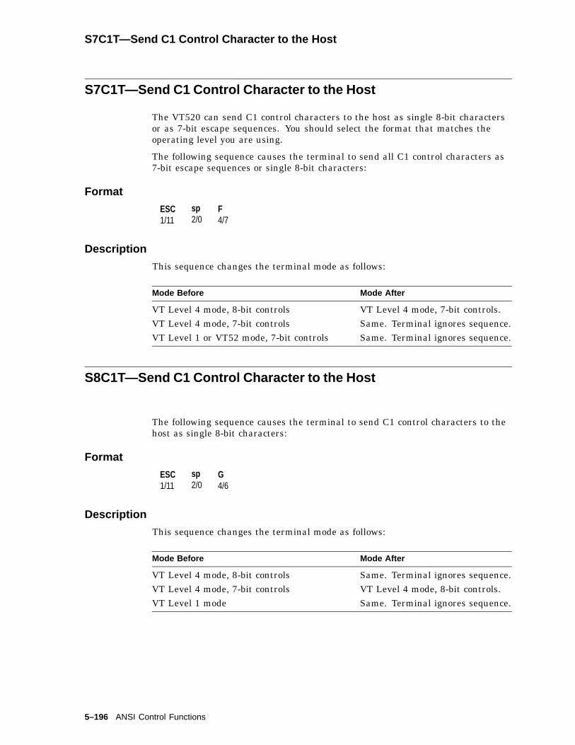
S7C1T—Send C1 Control Character to the Host
S7C1T—Send C1 Control Character to the Host
The VT520 can send C1 control characters to the host as single 8-bit charactersor as 7-bit escape sequences. You should select the format that matches theoperating level you are using.
The following sequence causes the terminal to send all C1 control characters as7-bit escape sequences or single 8-bit characters:
Format
ESC1/11
sp2/0
F4/7
Description
This sequence changes the terminal mode as follows:
Mode Before Mode After
VT Level 4 mode, 8-bit controls VT Level 4 mode, 7-bit controls.VT Level 4 mode, 7-bit controls Same. Terminal ignores sequence.VT Level 1 or VT52 mode, 7-bit controls Same. Terminal ignores sequence.
S8C1T—Send C1 Control Character to the Host
The following sequence causes the terminal to send C1 control characters to thehost as single 8-bit characters:
Format
ESC1/11
sp2/0
G4/6
Description
This sequence changes the terminal mode as follows:
Mode Before Mode After
VT Level 4 mode, 8-bit controls Same. Terminal ignores sequence.VT Level 4 mode, 7-bit controls VT Level 4 mode, 8-bit controls.VT Level 1 mode Same. Terminal ignores sequence.
5–196 ANSI Control Functions

SCS—Select Character Set
SCS—Select Character Set
Designate character sets to G-sets.
To understand how to select character sets, you must first understand thefunction of the terminal’s in-use table. The in-use table contains the charactersets the terminal can currently access. You can place any two character sets inthe terminal’s in-use table. The in-use table consists of the graphic left (GL) andgraphic right (GR) logical tables.
Each time you turn on the terminal, the terminal places the following defaultcharacter sets in the in-use table:
ASCII in GLSupplemental Graphic (or ISO Latin-1 supplemental) in GR
Together, the ASCII and Supplemental Graphic sets make up the Multinationalset. The ASCII and ISO Latin-1 supplemental sets make up the ISO Latin-1 set,which is the worldwide standard.
You can select a different character set by following these two steps:
1. Designate the set as G0, G1, G2, or G3.
G0 through G3 are logical sets that the terminal uses to access character sets.You can designate up to four character sets and have them ready for use inthe in-use table.
2. Map the designated set into the in-use table.
After you map the set into the in-use table, you can display or send anycharacter from that set by using 8-bit codes.
Designating Character Sets (SCS Sequences)
You designate a hard character set as G0 through G3 by using a select characterset (SCS) escape sequence. You cannot designate a 96-character set as G0.
SCS sequences use the following format. Table 5–14 lists the code used to selecteach available character set.
Format
ESC1/11
I1***
I2***
...
...In***
F***
Parameters
I1, intermediate characterDesignates the character set as G0, G1, G2, or G3.
ANSI Control Functions 5–197

Designating Character Sets (SCS Sequences)
Table 5–13 Designating a Character Set
I1 Character Code Set Selection
94-Character Sets( left parenthesis 2/8 G0 (initial setting for GL)) right parenthesis 2/9 G1* asterisk 2/10 G2 (initial setting for GR)+ plus sign 2/11 G396-Character Sets�
- hyphen 2/13 G1. period 2/14 G2/ slash 2/15 G3
�You cannot designate a 96-character set into G0.
I2...In F, intermediate and final charactersSelects one of the standard character sets. The following table lists the charactersused to select standard sets.
Table 5–14 Character Set Codes
Character Set I 2...In F Characters Code
94-Character SetsASCII(initial setting for G1 and G0)
B 4/2
DEC Supplemental Graphic(initial setting for G2 and G3)
%5 2/5, 3/5
DEC Special Graphic Set 0 3/0DEC Technical Character Set > 3/14User-preferred Supplemental Set < 3/12NRC SetsDEC Supplemental % 5 2/5, 3/5DEC Greek " ? 2/2, 3/15DEC Hebrew " 4 2/2, 3/4DEC Turkish % 0 2/5, 3/0DEC Cyrillic & 4 2/6, 3/4U.K. NRCS A 4/1French NRCS R 5/2French Canadian NRCS† 9 or Q 3/9 or 5/1Norwegian/Danish NRCS† ‘, E, or 6 6/0, 4/5,
or 3/6Finnish NRCS† 5 or C 3/5 or 4/3German NRCS K 4/11
†We recommend using the first code shown.
(continued on next page)
5–198 ANSI Control Functions
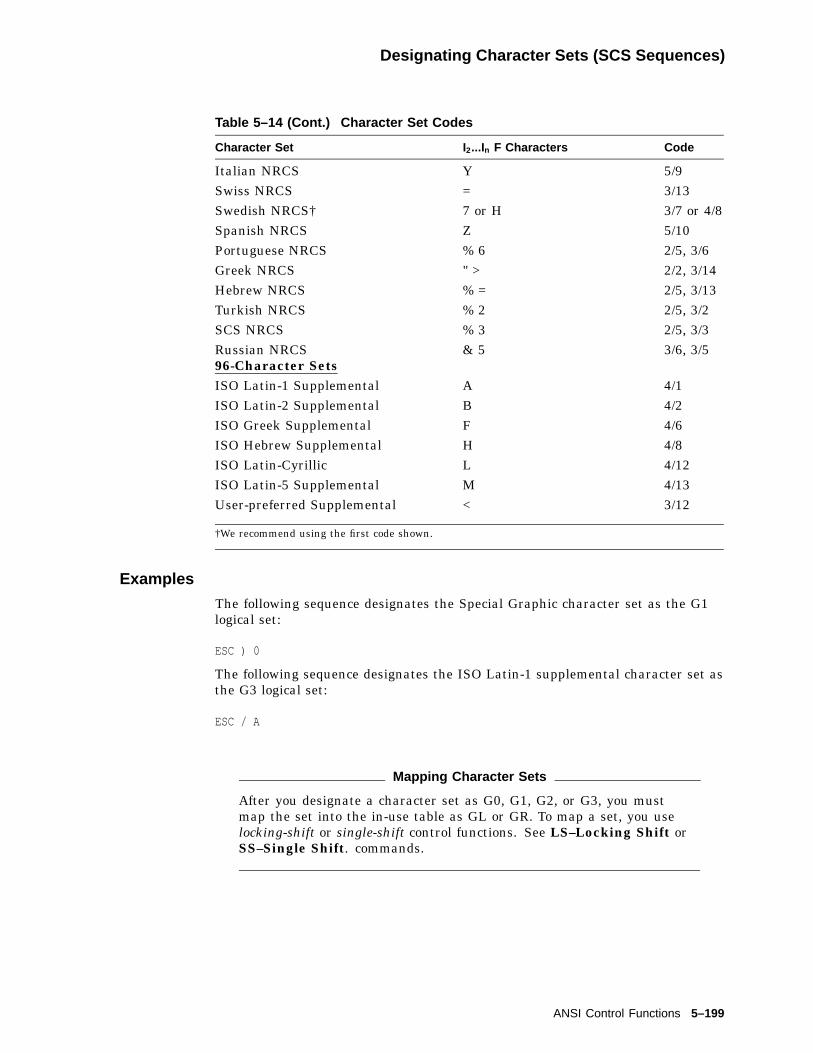
Designating Character Sets (SCS Sequences)
Table 5–14 (Cont.) Character Set Codes
Character Set I 2...In F Characters Code
Italian NRCS Y 5/9Swiss NRCS = 3/13Swedish NRCS† 7 or H 3/7 or 4/8Spanish NRCS Z 5/10Portuguese NRCS % 6 2/5, 3/6Greek NRCS " > 2/2, 3/14Hebrew NRCS % = 2/5, 3/13Turkish NRCS % 2 2/5, 3/2SCS NRCS % 3 2/5, 3/3Russian NRCS & 5 3/6, 3/596-Character SetsISO Latin-1 Supplemental A 4/1ISO Latin-2 Supplemental B 4/2ISO Greek Supplemental F 4/6ISO Hebrew Supplemental H 4/8ISO Latin-Cyrillic L 4/12ISO Latin-5 Supplemental M 4/13User-preferred Supplemental < 3/12
†We recommend using the first code shown.
Examples
The following sequence designates the Special Graphic character set as the G1logical set:
ESC ) 0
The following sequence designates the ISO Latin-1 supplemental character set asthe G3 logical set:
ESC / A
Mapping Character Sets
After you designate a character set as G0, G1, G2, or G3, you mustmap the set into the in-use table as GL or GR. To map a set, you uselocking-shift or single-shift control functions. See LS–Locking Shift orSS–Single Shift. commands.
ANSI Control Functions 5–199
SD—Pan Up
SD—Pan Up
This control function moves the user window up a specified number of lines inpage memory.
Format
CSI9/11
Pn3/n
T5/4
Parameters
Pnis the number of lines to move the user window up in page memory. Pn newlines appear at the top of the display. Pn old lines disappear at the bottom of thedisplay. You cannot pan past the top margin of the current page.
5–200 ANSI Control Functions
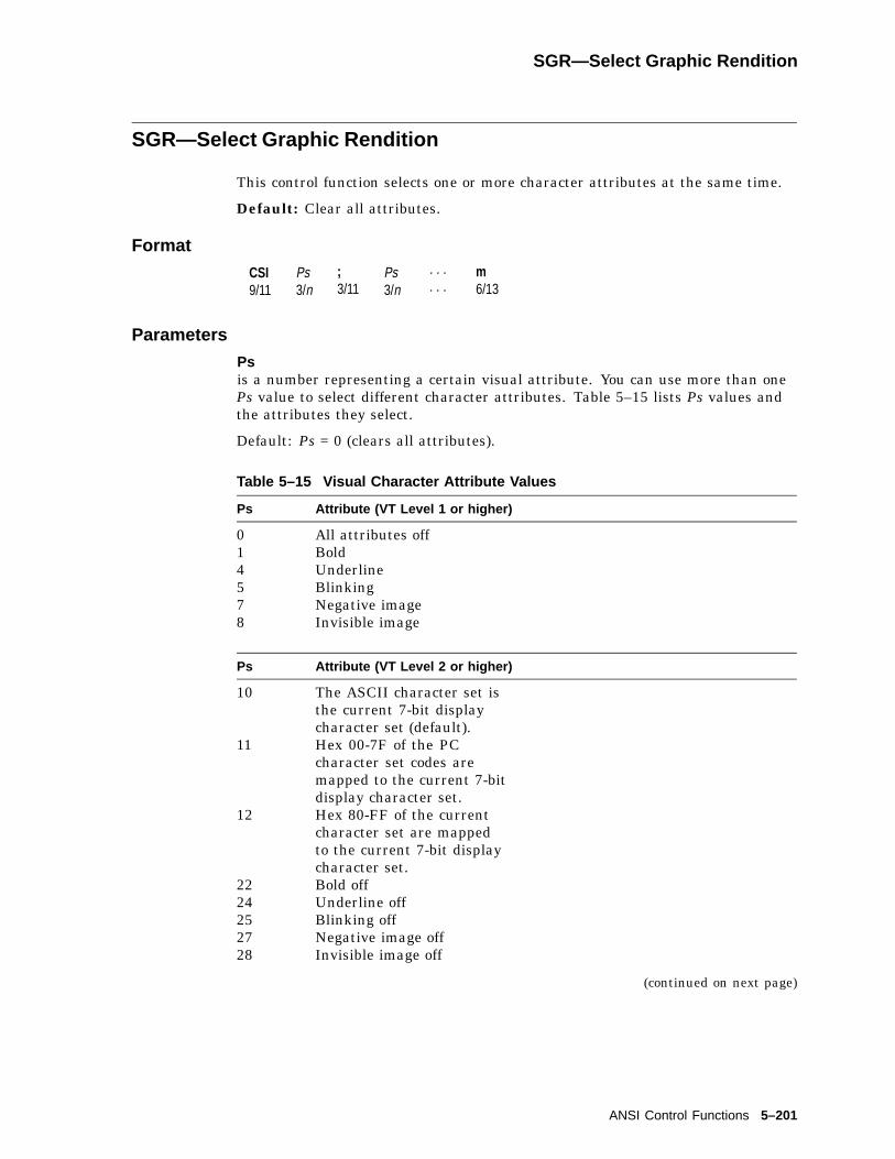
SGR—Select Graphic Rendition
SGR—Select Graphic Rendition
This control function selects one or more character attributes at the same time.
Default: Clear all attributes.
Format
CSI9/11
Ps3/n
;3/11
Ps3/n
. . .
. . .m6/13
Parameters
Psis a number representing a certain visual attribute. You can use more than onePs value to select different character attributes. Table 5–15 lists Ps values andthe attributes they select.
Default: Ps = 0 (clears all attributes).
Table 5–15 Visual Character Attribute Values
Ps Attribute (VT Level 1 or higher)
0 All attributes off1 Bold4 Underline5 Blinking7 Negative image8 Invisible image
Ps Attribute (VT Level 2 or higher)
10 The ASCII character set isthe current 7-bit displaycharacter set (default).
11 Hex 00-7F of the PCcharacter set codes aremapped to the current 7-bitdisplay character set.
12 Hex 80-FF of the currentcharacter set are mappedto the current 7-bit displaycharacter set.
22 Bold off24 Underline off25 Blinking off27 Negative image off28 Invisible image off
(continued on next page)
ANSI Control Functions 5–201

SGR—Select Graphic Rendition
Table 5–15 (Cont.) Visual Character Attribute Values
PsAttribute (VT Level 5, VT525only) 1 Default Color
30 Foreground Color 0 Black31 Foreground Color 1 Red32 Foreground Color 2 Green33 Foreground Color 3 Yellow34 Foreground Color 4 Blue35 Foreground Color 5 Magenta36 Foreground Color 6 Cyan37 Foreground Color 7 White39 Default Foreground Color White40 Background Color 0 Black41 Background Color 1 Red42 Background Color 2 Green43 Background Color 3 Yellow44 Background Color 4 Blue45 Background Color 5 Magenta46 Background Color 6 Cyan47 Background Color 7 White49 Default Background Color Black
1ANSI color text extension (DA1 reports 22 for VT525 and VGB25 only).
Examples
When you select more than one attribute in an SGR sequence, then they areexecuted in order. For example, you can use the following sequence to displaytext that is bold, blinking, and underlined:
CSI 0 ; 1 ; 5 ; 4 m
The following sequence displays the negative image of text:
CSI 7 m
Notes on SGR
• After you select an attribute, the terminal applies that attribute to all newcharacters received. If you move characters by scrolling, then the attributesmove with the characters.
• If you display control characters, then the terminal ignores the bold attributefor displayed control characters.
• Color renditions may be selected in any combination. Selecting additionalrenditions do not affect the setting of previously selected renditions orcharacters already on the display unless all renditions are turned off(parameter value 0).
5–202 ANSI Control Functions

SGR—Select Graphic Rendition
When a PC character set is selected:
Command (Hexadecimal) Display Character
Executing "CSI 10 m" 00-1F: control codes20-7F: ASCII characters80-FF: 8 bit PC characters
Executing "CSI 11 m" 00-1F: PC characters, except the following codeswhen XON/XOFF is enabled:
1B (ESC)11 (DC1)13 (DC3)
20-7F: ASCII characters (or PC 7 bit character)80-FF: 8 bit PC characters
Executing "CSI 12 m" 00-1F: PC characters that are located in 80 - 9Fin PC character set, except the following codeswhen XON/XOFF is enabled:
9B (ESC)91 (DC1)93 (DC3)
20-7F: PC characters located in A0-FF80-FF: 8 bit PC characters.
For ISO/ANSI character set:
Command (Hexadecimal) Display Character
Executing "CSI 10 m" 00-1F: control codes20-7F: ASCII characters80-9F: control codeA0-FF: GR characters
Executing "CSI 12 m" 00-1F: control codes20-7F: ISO/ANSI characters located in A0-FF80-9F: control codeA0-FF: GR characters
Commands "CSI 10-12 m" affect only the Hex 00-7F portion of the displaycharacter set. The hex 80-FF region of the display character set is left intact.
The ASCII character set with control codes residing in Hex 00 to 1F region isthe default 7-bit display character set. This is true regardless of the ISO/ANSIor PC character set. When in an ISO/ANSI character set, issuing "CSI 10 m" isequivalent to "designating and invoking ASCII to G0 and GL."
ANSI Control Functions 5–203
SGR—Select Graphic Rendition
When "ESC 11 m" is executed, the display character set is loaded with codes inthe Hex 00 to 7F region of a PC character set. PC characters whose code valuesare less than 1F can be displayed through this sequence except 1B (ESC) and11(DC1), 13(DC3) when XON/XOFF is enabled. 1B is always executed as anESC to allow the application to execute the command to go back to the defaultcharacter set. Hex 11 and 13 can be displayed only when XON/XOFF is disabled.This command does not work when the ISO/ANSI character set is selected.
Command "ESC 12 m" toggles the high bit of the current 8-bit character set. Allthe characters in Hex 80-FF region can be displayed as 7-bit codes except 9B(ESC) and 91(DC1), 93(DC3) when XON/XOFF is enabled. After the command isexecuted, 1B is executed as an ESC. Hex 11 and 13 can be displayed only whenXON/XOFF is disabled.
When in an ISO/ANSI character set, issuing "CSI 12 m" is equivalent to"designating and invoking current 8 bit char set to G2 and GL."
SRM—Local Echo: Send/Receive Mode
This control function turns local echo on or off. When local echo is on, theterminal sends keyboard characters to the screen. The host does not have to send(echo) the characters back to the terminal display. When local echo is off, theterminal only sends characters to the host. It is up to the host to echo charactersback to the screen.
Default: No local echo
Format
CSI9/11
13/1
23/2
h6/8
Set: local echo off.
CSI9/11
13/1
23/2
l6/12
Reset: local echo on.
Description
When the SRM function is set, the terminal sends keyboard characters to thehost only. The host can echo the characters back to the screen.
When the SRM function is reset, the terminal sends keyboard characters tothe host and to the screen. The host does have to echo characters back to theterminal.
5–204 ANSI Control Functions

SS—Single Shifts
SS—Single Shifts
You use a single shift when you want to display the next character from adifferent character set. A single shift maps the G2 or G3 set into GL. Thecharacter set is active for only one character, then the terminal returns to theprevious character set in GL.
The terminal has two single-shift control functions available.
FormatSingle-ShiftControl
8-BitCharacter
7-Bit EquivalentSequence Function
Single shift 2 SS28/14
ESC1/11
N4/14
Maps G2 into GL for thenext character.
Single shift 3 SS38/15
ESC1/11
O4/15
Maps G3 into GL for thenext character.
Example
Suppose the ASCII character set is in GL. You want to display the alphacharacter from the DEC Technical character set, already designated as G3.You do not want to replace the ASCII set just to display one character. Instead,you can use single shift 3 to temporarily map the DEC Technical set (G3) into GL.
SS3single shift 3
aalpha character
After displaying the alpha character, the terminal maps the ASCII set (G1) backinto GL, replacing the DEC Technical set (G3).
ANSI Control Functions 5–205

SM—Set Mode
SM—Set Mode
This control function has two versions. You use the ANSI version to set one ormore ANSI modes. You use the DEC private version to set one or more DECprivate modes. You cannot set ANSI and DEC private modes with the same SMsequence.
Setting DEC Private Modes
CSI9/11
?3/15
Pd3/n
;3/11
. . .
. . .Pd3/n
h6/8
Parameters
Pdindicates a DEC private mode to set. Table 5–5 lists the Pd values for DECprivate modes. You can use more than one Pd value in a sequence.
Examples
DEC Private ModesThe following sequence sets (Hebrew) keyboard mapping (DECHEBM) andHebrew encoding mode (DECHEM):
CSI ? 34; 36 h
34 indicates (Hebrew) keyboard mapping.36 indicates Hebrew encoding mode.
Programming TipApplications can use the SM and RM functions to restore any number of VT520modes to a desired state. See the Report Mode (DECRPM) section in this chapterfor details.
5–206 ANSI Control Functions
SU—Pan Down
SU—Pan Down
This control function moves the user window down a specified number of lines inpage memory.
Format
CSI9/11
Pn3/n
S5/3
Parameters
Pnis the number of lines to move the user window down in page memory. Pn newlines appear at the bottom of the display. Pn old lines disappear at the top of thedisplay. You cannot pan past the bottom margin of the current page.
TBC—Tab Clear
This control function clears tab stops.
Format
CSI9/11
Ps3/n
g6/7
Parameters
Psindicates the tab stops to clear. There are only two values for Ps, 0 and 3.
0 or none(default)
The terminal only clears the tab stop at the cursor.
3 The terminal clears all tab stops.
ANSI Control Functions 5–207
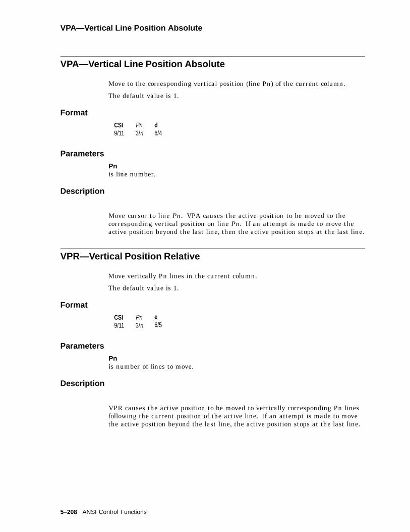
VPA—Vertical Line Position Absolute
VPA—Vertical Line Position Absolute
Move to the corresponding vertical position (line Pn) of the current column.
The default value is 1.
Format
CSI9/11
Pn3/n
d6/4
Parameters
Pnis line number.
Description
Move cursor to line Pn. VPA causes the active position to be moved to thecorresponding vertical position on line Pn. If an attempt is made to move theactive position beyond the last line, then the active position stops at the last line.
VPR—Vertical Position Relative
Move vertically Pn lines in the current column.
The default value is 1.
Format
CSI9/11
Pn3/n
e6/5
Parameters
Pnis number of lines to move.
Description
VPR causes the active position to be moved to vertically corresponding Pn linesfollowing the current position of the active line. If an attempt is made to movethe active position beyond the last line, the active position stops at the last line.
5–208 ANSI Control Functions

6SCO Console Emulation
This chapter describes the SCO Console mode.
6.1 SCO Console Emulation ModeSCO Console mode is a terminal emulation mode. It uses ANSI sequences withminor modifications to act like a SCO UNIX operating system console on a PC.
Depending on the terminal status, SCO Console mode for the VT520 transmitsASCII characters (default) or scancode to the host when keys are pressed. Userscan specify a keycode mode by issuing an escape sequence (DECPCTERM) orby keyboard encoding of Set-Up. When in SCO Console mode with the ASCIIkeycode selected, the terminal behavior is similar to VT mode. When in SCOConsole mode with scancode selected, the terminal behavior is similar to VTPCTerm mode. Table 6–1 shows the similarities and differences.
Table 6–1 SCO Console Mode with ASCII Keycodes and Scancodes
SCO Console Mode with
Default ASCII Keycodes Scancodes VT Mode VT PCTerm
Screen display 25�80 25�80 24�80 25�80
Autowrap On On Off On
Autowrapbehavior
Like WYSE Like WYSE Like VT Like VT
Status line None None Local None
Cursor positionwhile switchingpages
Saved Saved Not saved Not saved
Character set PCTerm (including PC, ISO/ANSIcharacter sets)
VT character set(ISO/ANSI)
PCTerm characterset
CSI 10-12 m Supported Supported Not supported Not supported
SUSD
Acts like INDActs like RI
Acts like INDActs like RI
Acts like SUActs like SD
Acts like SUActs like SD
CSI s and CSI uDECSC andDECRC
SupportedSupported
SupportedSupported
Only DECSC and DECRC are supported.
CSI Pn z(switch pages)
Supported Supported Not supported Not supported
ESC Q Fn String(Define Function)
Supported Supported Not supported Not supported
Transmit flowcontrol
None None XON/XOFF None
SCO Console Emulation 6–1

SCO Console Emulation6.1 SCO Console Emulation Mode
6.1.1 KeyboardSCO Console mode works with either a PC keyboard or a VT keyboard attached.
6.1.1.1 Local Function Keys in SCO Console ModeThe keys used to perform local functions in SCO Console mode are similar tothose used for VT mode (see Chapter 8, Keyboard Processing. Table 6–2 showsthe exceptions).
Table 6–2 Local Functions on VT and Enhanced PC Layouts
Fn# Function VT Layout EPC Layout
1 Hold CapsLock/F1 Scroll CapsLock
2 Print CapsLock/F2 Print Screen
3 Set-Up CapsLock/F3 CapsLock/Print Screen ,Alt/Print Screen
5 Break CapsLock/F5 CapsLock/Pause
7 Hard Reset CapsLock/Ctrl/F3 Ctrl/CapsLock/Print Screen
8 Toggle Autoprint CapsLock/Ctrl/F2 Ctrl/Print Screen
9 Disconnect CapsLock/Shift/F5 Shift/CapsLock/Pause
10 Send Answerback CapsLock/Ctrl/F5 Ctrl/CapsLock/Pause
11 Print ComposedMain Display
Not supported
20 Pan Up Not supported
21 Pan Down Not supported
24 Pan Prev Page Not supported
25 Pan Next Page Not supported
30 Copy and Paste CapsLock/F1 Scroll Lock
47 Primary KBlanguage
CapsLock/Ctrl/Alt/F1 CapsLock/Ctrl/Alt/F1
48 Secondary KBlanguage
CapsLock/Ctrl/Alt/F2 CapsLock/Ctrl/Alt/F2
53 ±DEC/IBM PC Style Not supported
6.1.1.2 PC KeyboardTables 6–3 through 6–6 list the default codes sent by keys in ASCII charactercode mode.
The keys that can be affected by Caps Lock or Num Lock send a shifted valuewhen in Lock state. If Shift is pressed when Caps Lock or Num Lock is in effect,the key sends its unshifted value. This "Reverse Lock" is the default for a CapsLock function.
Alt has no effect on the key pressed unless otherwise indicated. A blank in anycolumn means the keystroke is not defined.
6–2 SCO Console Emulation

SCO Console Emulation6.1 SCO Console Emulation Mode
Table 6–3 SCO Console Mode Function Key Default Codes
Key Unmodified Shift Ctrl Ctrl/Shift
F1 ESC[M ESC[Y ESC[k ESC[w
F2 ESC[N ESC[Z ESC[l ESC[x
F3 ESC[O ESC[a ESC[m ESC[y
F4 ESC[P ESC[b ESC[n ESC[z
F5 ESC[Q ESC[c ESC[o ESC[@
F6 ESC[R ESC[d ESC[p ESC[[
F7 ESC[S ESC[e ESC[q ESC[<
F8 ESC[T ESC[f ESC[r ESC[ ]
F9 ESC[U ESC[g ESC[s ESC[^
F10 ESC[V ESC[h ESC[t ESC[_
F11 ESC[W ESC[i ESC[u ESC[’
F12 ESC[X ESC[j ESC[v ESC[{
Print Screen Print Screen ESC[0i
Scroll Lock Scroll Lock Scroll Lock N/A N/A
Pause Break Break N/A N/A
Table 6–4 SCO Console Mode Main Keypad Default Codes
Key Unmodified Shift Ctrl Ctrl/Shift
ESC ESC ESC ESC ESC
1 1 ! 1 !
2 2 @ Nul Nul
3 3 # ESC ESC
4 4 $ FS FS
5 5 % GS GS
6 6 ^ RS RS
7 7 & US US
8 8 * DEL DEL
9 9 (
0 0 )
- - _ US US
= = +
Backspace BS BS DEL DEL
Tab HT ESC[Z
q q Q DC1 DC1
w w W ETB ETB
e e E ENQ ENQ
r r R DC2 DC2
(continued on next page)
SCO Console Emulation 6–3
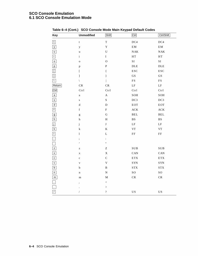
SCO Console Emulation6.1 SCO Console Emulation Mode
Table 6–4 (Cont.) SCO Console Mode Main Keypad Default Codes
Key Unmodified Shift Ctrl Ctrl/Shift
t t T DC4 DC4
y y Y EM EM
u u U NAK NAK
i i I HT HT
o o O SI SI
p p P DLE DLE
[ [ { ESC ESC
] ] } GS GS
\ \ | FS FS
Return CR CR LF LF
Ctrl Ctrl Ctrl Ctrl Ctrl
a a A SOH SOH
s s S DC3 DC3
d d D EOT EOT
f f F ACK ACK
g g G BEL BEL
h h H BS BS
j j J LF LF
k k K VT VT
l l L FF FF
; ; :
’ ’ "
z z Z SUB SUB
x x X CAN CAN
c c C ETX ETX
v v V SYN SYN
b b B STX STX
n n N SO SO
m m M CR CR
, , <
. . >
/ / ? US US
6–4 SCO Console Emulation

SCO Console Emulation6.1 SCO Console Emulation Mode
Table 6–5 SCO Console Mode Numeric Keypad Default Codes, Num Lock Off
Keypad Key Unmodified Shift Ctrl Ctrl/Shift
Num Lock Num Lock Num Lock DC3 DC3
/ / /
* * *
7 ESC[H 7 ESC[H 7
8 ESC[A 8 ESC[A 8
9 ESC[I 9 ESC[I 9
- - - - -
4 ESC[D 4 ESC[D 4
5 ESC[E 5 ESC[E 5
6 ESC[C 6 ESC[C 6
+ + + + +
1 ESC[F 1 ESC[F 1
2 ESC[B 2 ESC[B 2
3 ESC[G 3 ESC[G 3
0 ESC[L 0 ESC[L 0
. DEL . DEL DEL
Enter CR CR LF LF
Table 6–6 SCO Console Mode Numeric Keypad Default Codes, Num Lock On
Keypad Key Unmodified Shift Ctrl Ctrl/Shift
Numlock Numlock Numlock DC3 DC3
/ / /
* * *
7 7 ESC[H
8 8 ESC[A
9 9 ESC[I
- - - - -
4 4 ESC[D
5 5 ESC[E
6 6 ESC[C
+ + +
1 1 ESC[F
2 2 ESC[B
3 3 ESC[G
0 0 ESC[L
. . DEL
Enter CR CR
SCO Console Emulation 6–5
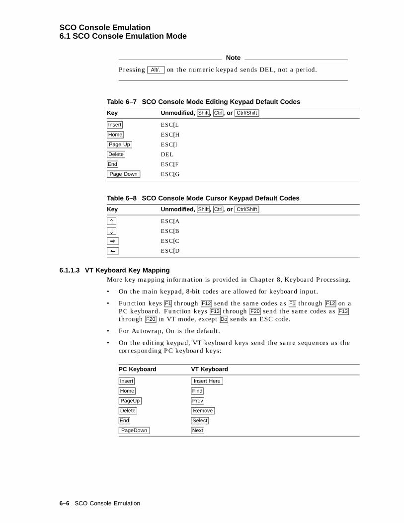
SCO Console Emulation6.1 SCO Console Emulation Mode
Note
Pressing Alt/. on the numeric keypad sends DEL, not a period.
Table 6–7 SCO Console Mode Editing Keypad Default Codes
Key Unmodified, Shift , Ctrl , or Ctrl/Shift
Insert ESC[L
Home ESC[H
Page Up ESC[I
Delete DEL
End ESC[F
Page Down ESC[G
Table 6–8 SCO Console Mode Cursor Keypad Default Codes
Key Unmodified, Shift , Ctrl , or Ctrl/Shift
* ESC[A
+ ESC[B
) ESC[C
( ESC[D
6.1.1.3 VT Keyboard Key MappingMore key mapping information is provided in Chapter 8, Keyboard Processing.
• On the main keypad, 8-bit codes are allowed for keyboard input.
• Function keys F1 through F12 send the same codes as F1 through F12 on aPC keyboard. Function keys F13 through F20 send the same codes as F13
through F20 in VT mode, except Do sends an ESC code.
• For Autowrap, On is the default.
• On the editing keypad, VT keyboard keys send the same sequences as thecorresponding PC keyboard keys:
PC Keyboard VT Keyboard
Insert Insert Here
Home Find
PageUp Prev
Delete Remove
End Select
PageDown Next
6–6 SCO Console Emulation
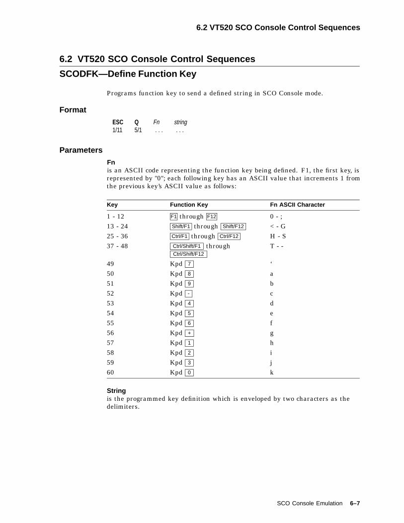
6.2 VT520 SCO Console Control Sequences
6.2 VT520 SCO Console Control Sequences
SCODFK—Define Function Key
Programs function key to send a defined string in SCO Console mode.
Format
ESC1/11
Q5/1
Fn. . .
string. . .
Parameters
Fnis an ASCII code representing the function key being defined. F1, the first key, isrepresented by "0"; each following key has an ASCII value that increments 1 fromthe previous key’s ASCII value as follows:
Key Function Key Fn ASCII Character
1 - 12 F1 through F12 0 - ;13 - 24 Shift/F1 through Shift/F12 < - G25 - 36 Ctrl/F1 through Ctrl/F12 H - S37 - 48 Ctrl/Shift/F1 through
Ctrl/Shift/F12T - -
49 Kpd 7 ‘50 Kpd 8 a51 Kpd 9 b52 Kpd - c53 Kpd 4 d54 Kpd 5 e55 Kpd 6 f56 Kpd + g57 Kpd 1 h58 Kpd 2 i59 Kpd 3 j60 Kpd 0 k
Stringis the programmed key definition which is enveloped by two characters as thedelimiters.
SCO Console Emulation 6–7
SCODFK—Define Function Key
Description
The first character after the ASCII character representing a function key becomesthe delimiter. It looks for an identical character as the second and final delimiter.If string is too long and no memory is available, then the command stringis aborted and remaining characters are displayed on screen. The characterbecomes the final character. All the following characters are displayed on thescreen.
Example:
Executing "ESC Q 0 ’abcdefghij’klmnopq" when 100 bytes of memory isavailable defines the string "abcdefghij" into F1 function key and displays"klmnopq" on the screen.
If you execute the same sequence when only a 4 byte string is allowed, then thewhole sequence is aborted.
A "^" character causes any following character to subtract 32 from its ASCIIvalue. For example, "^e" in the string sends "E" when the key is pressed.
Any code in the 00-7F region can be defined. An 8-bit code entered is stripped ofits eighth bit and defined as a corresponding 7-bit code.
For example, executing ESCQ0’F1KEY’ defines string F1KEY for function key F1;ESC1aF2KEYa defines string F2key for F2.
The maximum string length for a defined key is 255 characters.
SCODPCC—Display PC Characters
Displays C0 controls (lower 32 bytes) as PC characters for SCO Console mode.
Format
ESC1/11
xxhex value
Description
SCO Console allows "ESC xx" to work when the PC character set is selected anddisplayable characters are mapped in the 00-1F region (when either "CSI 11 m"or "CSI 12 m" is executed). The command allows the character in 1B location tobe displayed; 1B is always executed as an ESC control code under "CSI 11 or 12m" (See SGR).
6–8 SCO Console Emulation
SCORC—Restore Saved Cursor Position
SCORC—Restore Saved Cursor Position
Moves cursor to the position saved by save cursor command in SCO console mode.
Format
CSI9/11
u7/5
Description
This command acts the same as the DECRC command, except that the cursorstays at the same page instead of moving to a page where the cursor was saved.
SCOSC—Save Current Cursor Position
Saves current cursor position for SCO console mode.
Format
CSI9/11
s7/3
Description
This command acts the same as the DECSC command, except that the pagenumber where the cursor is located is not saved as a result of executing thecommand.
SCO Console Emulation 6–9

7Character Sets
This chapter describes the character sets supported by the VT520 video terminal.
7.1 OverviewThe VT520 video terminal supports most character sets for Eastern Europe,Cyrillic, Greek, Hebrew, and Turkish character sets. In addition to traditionalDEC and ISO character sets the VT520 supports a number of IBM PC code pages(which refer to page numbers in IBM’s standard character set manual) in PCTermmode to emulate the console terminal of industry-standard PCs.
Each code page defines both the exact repertoire (set of characters) and theassignment of code positions in the 0 - 255 range. Once configured, the code pageis not usually changed within a single application.
7.2 Character Sets SupportedThe following sections list the characters sets supported by the VT520 terminal.
7.2.1 VT Graphic Character SetsThe VT520 supports the following VT 8-bit multinational character sets:
• ISO Latin-1
• ISO Latin-2
• ISO Latin-Cyrillic
• ISO Latin-Greek
• ISO Latin-Hebrew
• ISO Latin-5
• KOI-8 Cyrillic
• DEC Multinational
• DEC Greek
• DEC Hebrew
• DEC Turkish
The VT520 also supports the following character sets:
• DEC Special Graphics (VT100 Line Drawing set)
• DEC Technical Character set
Character Sets 7–1

Character Sets7.2 Character Sets Supported
When 7-bit NRCS Characters is selected, a corresponding 7-bit or NRC set isused depending on the keyboard language selected. (See Chapter 8 for details.)
• U.K. NRC (ISO)
• French NRC (ISO)
• DEC French Canadian NRC
• Norwegian/Danish NRC (ISO)
• DEC Finnish NRC
• German NRC (ISO)
• Italian NRC (ISO)
• DEC Swiss NRC
• Swedish NRC (ISO)
• Spanish NRC (ISO)
• DEC Portuguese NRC
• SCS NRC
• Russian 7-bit (KOI-7)
• DEC 7-bit Greek
• DEC 7-bit Hebrew
• DEC 7-bit Turkish
7.2.2 PCTerm Graphic Character SetsWhen PCTerm mode is selected, the terminal can still use all the VT 8-bitcharacter sets listed in Section 7.2.1. Additionally, the following PC code pagesare supported:
• PC International (437)
• PC Multilingual (850)
• PC Slavic (852)
• PC Greek (210)
• PC Spanish (220)
• PC Turkish (857)
• PC Portuguese (860)
• PC Hebrew (862)
• PC French/Canadian (863)
• PC Danish/Norwegian (865)
• PC Cyrillic (866)
Note
7-bit NRC sets are not available in PCTerm mode.
7–2 Character Sets
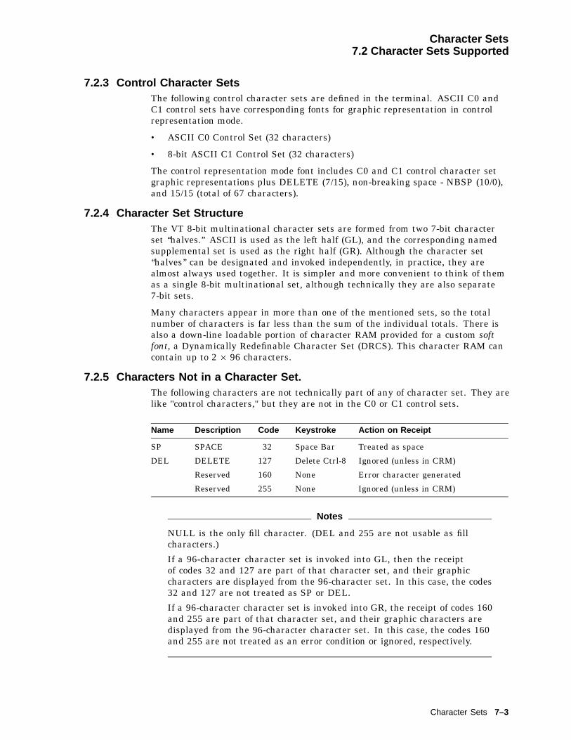
Character Sets7.2 Character Sets Supported
7.2.3 Control Character SetsThe following control character sets are defined in the terminal. ASCII C0 andC1 control sets have corresponding fonts for graphic representation in controlrepresentation mode.
• ASCII C0 Control Set (32 characters)
• 8-bit ASCII C1 Control Set (32 characters)
The control representation mode font includes C0 and C1 control character setgraphic representations plus DELETE (7/15), non-breaking space - NBSP (10/0),and 15/15 (total of 67 characters).
7.2.4 Character Set StructureThe VT 8-bit multinational character sets are formed from two 7-bit characterset ‘‘halves.’’ ASCII is used as the left half (GL), and the corresponding namedsupplemental set is used as the right half (GR). Although the character set‘‘halves’’ can be designated and invoked independently, in practice, they arealmost always used together. It is simpler and more convenient to think of themas a single 8-bit multinational set, although technically they are also separate7-bit sets.
Many characters appear in more than one of the mentioned sets, so the totalnumber of characters is far less than the sum of the individual totals. There isalso a down-line loadable portion of character RAM provided for a custom softfont, a Dynamically Redefinable Character Set (DRCS). This character RAM cancontain up to 2 � 96 characters.
7.2.5 Characters Not in a Character Set.The following characters are not technically part of any of character set. They arelike "control characters," but they are not in the C0 or C1 control sets.
Name Description Code Keystroke Action on Receipt
SP SPACE 32 Space Bar Treated as space
DEL DELETE 127 Delete Ctrl-8 Ignored (unless in CRM)
Reserved 160 None Error character generated
Reserved 255 None Ignored (unless in CRM)
Notes
NULL is the only fill character. (DEL and 255 are not usable as fillcharacters.)
If a 96-character character set is invoked into GL, then the receiptof codes 32 and 127 are part of that character set, and their graphiccharacters are displayed from the 96-character set. In this case, the codes32 and 127 are not treated as SP or DEL.
If a 96-character character set is invoked into GR, the receipt of codes 160and 255 are part of that character set, and their graphic characters aredisplayed from the 96-character character set. In this case, the codes 160and 255 are not treated as an error condition or ignored, respectively.
Character Sets 7–3
Character Sets7.3 VT Mode
7.3 VT ModeAll DEC character sets are supported in VT500 mode with either a VT keyboardor an attached Enhanced PC keyboard.
In VT100 mode, VT52 mode, or when 7-bit NRCS characters is selected(through Set-Up or DECNRCM), only ASCII, NRC sets, and DEC Special Graphiccharacters are available.
7.3.1 Selecting Character SetsCharacter sets are designated with the select character set (SCS) control function.Refer to Chapter 5 for more details.
7.3.2 Character Set MappingsThe following table lists the character set mappings.
Character Set Mapped onto decimal . . .
C0 controls 0 to 31
Space 32
ASCII, all other NRC sets, Line Drawing, DECTechnical set, DEC 7-Bit Greek, DEC 7-BitHebrew, or DEC 7-Bit Turkish
33 to 126
DEL 127
C1 controls 128 to 159
10/0 160
DEC Multinational Graphic, 161 to 254
15/15 255
ISO Latin-1 Supplemental Graphic,ISO Latin-2 Supplemental Graphic,ISO Latin-Cyrillic, ISO Latin-Greek,ISO Latin-Hebrew, or ISO Latin-5.
160 to 255
These are typical assignments. By appropriate designating and invokingsequences, other mappings are possible for the graphic character sets.
7.4 PCTerm ModeThis section describes how to select character sets in PCTerm mode.
7.4.1 Selecting Character SetsIf a PC character set is selected, then all the SCS sequences used to designateand invoke character sets into G0, G1, G2, G3, GL, and GR (including single andlocking shifts) are ignored. You select the character set through a Set-Up field oran escape sequence, DECPCTERM. You can use only one code page containing256 characters at a time.
If you use a DEC character set, all the SCS and invocation sequences continue towork normally.
7–4 Character Sets
Character Sets7.4 PCTerm Mode
7.4.2 Character Set MappingsIf DEC character sets are in use, all the character set mappings follow the VTmode convention. C0 and C1 regions are all control codes.
In PC character sets, the conventional ISO C1 region, (80 hex through 9F hex) areall displayable character codes. The VT520 does not recognize control sequencesthat have 8-bit control codes; therefore, the 8-bit control mode becomes invalid.
The C0 region (00 hex through 1F hex) in a PC character set is mixed withcontrol characters and graphic characters. Among them, 11 locations can haveboth control characters and displayable characters in the same locations; otherlocations are occupied by displayable characters only. The 11 C0 locations include0/5, 0/7, 0/8, 0/9, 0/A, 0/B, 0/C, 0/D, 1/1, 1/3, and 1/B.
Control codes are used for ENQ, BEL, BS, HT, LF, VT, FF, CR, DC1, DC3, andESC operations.
You access the displayable characters by preceding the C0 control code with ESCto form a 2-byte pair (1Bh XXh). These 2-byte pairs, such as ESC C0, are onlyrecognized in PCTerm mode.
7.5 SCO Console ModeSCO console mode can use both VT character sets and PC character sets. Youselect a VT character set through the PCTerm character set field in Set-Up,or you can use an SCS invocation sequence. You can select a PC character setthrough the same Set-Up field, or you can use the DECPCTERM escape sequence.
Note
All the character sets can be displayed on the screen.
7.6 Soft Character SetsYou can download soft character set from the host system into the terminal. Thisfeature lets you design your own soft character sets for use with the terminal.You can only load soft character sets in VT Level 4 or higher.
The control string command to down-line load the soft character sets is DECDLD.The DECDLD command down-line loads one or more characters of a specified 94-or 96-character dynamically redefinable character set (DRCS) with a specifiedlogical pixel pattern. The affected characters in the DRCS set also change thepresentation of characters from the set currently being displayed on the screen.The DECDLD control does not clear the screen.
See Chapter 5 for a description of the DECDLD—Dynamically RedefinableCharacter Sets Extension command.
Note
VT220 or VT320 fonts may appear different on a VT520 terminal, becausethe character cell sizes are different from those terminals. See thePcmw parameter in DECDLD—Dynamically Redefinable Character SetsExtension.
Character Sets 7–5
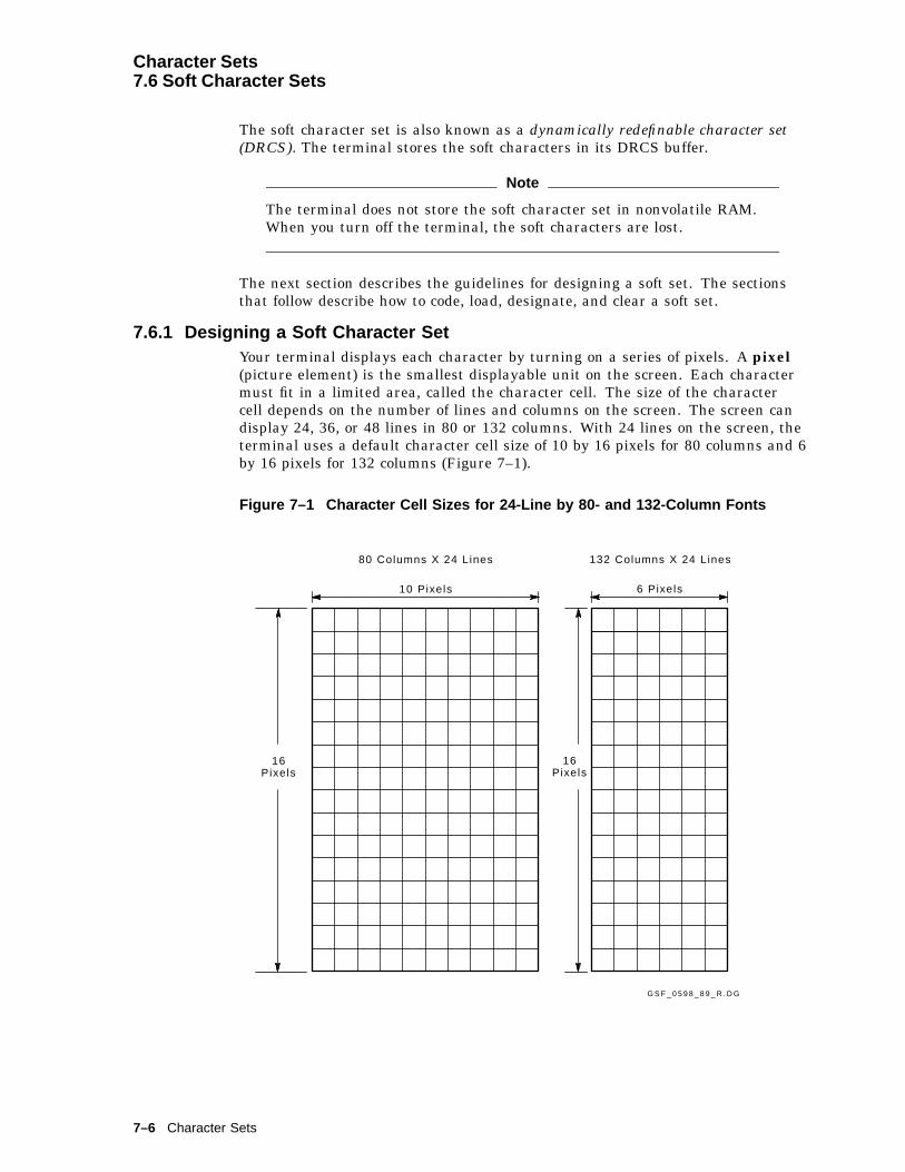
Character Sets7.6 Soft Character Sets
The soft character set is also known as a dynamically redefinable character set(DRCS). The terminal stores the soft characters in its DRCS buffer.
Note
The terminal does not store the soft character set in nonvolatile RAM.When you turn off the terminal, the soft characters are lost.
The next section describes the guidelines for designing a soft set. The sectionsthat follow describe how to code, load, designate, and clear a soft set.
7.6.1 Designing a Soft Character SetYour terminal displays each character by turning on a series of pixels. A pixel(picture element) is the smallest displayable unit on the screen. Each charactermust fit in a limited area, called the character cell. The size of the charactercell depends on the number of lines and columns on the screen. The screen candisplay 24, 36, or 48 lines in 80 or 132 columns. With 24 lines on the screen, theterminal uses a default character cell size of 10 by 16 pixels for 80 columns and 6by 16 pixels for 132 columns (Figure 7–1).
Figure 7–1 Character Cell Sizes for 24-Line by 80- and 132-Column Fonts
G S F _ 0 5 9 8 _ 8 9 _ R . D G
80 Columns X 24 Lines 132 Columns X 24 Lines
10 Pixels 6 Pixels
16Pixels
16Pixels
7–6 Character Sets

Character Sets7.6 Soft Character Sets
Table 7–1 shows the default character cell widths and heights based on thenumber of lines and columns on the screen.
Table 7–1 Character Cell Sizes
Cell Size 80 Columns 132 Columns
24 Lines/Screen
Width 10 pixels 6 pixels
Height 16 16
36 Lines/Screen
Width 10 6
Height 10 10
48 Lines/Screen
Width 10 6
Height 8 8
When you design a character, you should lay out a character cell on grid paper.The little boxes on the grid paper represent pixels. You fill in the pixels thatmake up the character. The next section shows an example of a character design.
You should design six versions of your character set to fit six different charactercell sizes. This means that there will be a version of your soft character set to fitany combination of lines and columns available on the terminal:
24 lines � 80 columns24 lines � 132 columns36 lines � 80 columns36 lines � 132 columns48 lines � 80 columns48 lines � 132 columns
Design your character set, then load six versions of the set, one for each possibleline/column combination. The terminal automatically selects which version of theset to use, based on the current number of lines and columns on the screen.
The terminal’s built-in fonts follow the guidelines in Table 7–2, which lists thedifferent guidelines for characters displayed with 24 lines, 36 lines, or 48 lines onthe screen. In all cases, the screen resolution is 800 by 400 pixels for 80 columns,792 by 400 pixels for 132 columns. The pixel aspect ratio is 1:1.4.
You must design your characters to fit the cell. The terminal ignores any pixelsthat are defined outside the cell. Also, you should include empty pixels on theleft or right side of the character cell to allow for space between characters.Figure 7–2 shows an example of spacing for an uppercase D character with 24lines on the screen. In this example, the character for the 80-column font has twopixel columns reserved for spacing.
Character Sets 7–7
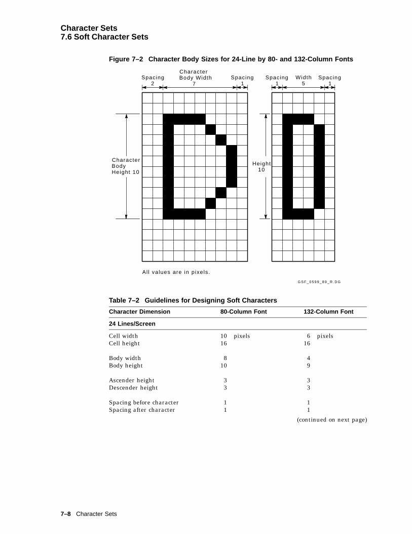
Character Sets7.6 Soft Character Sets
Figure 7–2 Character Body Sizes for 24-Line by 80- and 132-Column Fonts
G S F _ 0 5 9 9 _ 8 9 _ R . D G
Spacing2
CharacterBody Width
7Spacing
1Width
5
CharacterBodyHeight 10
Height10
Spacing1
Spacing1
Al l values are in pixels.
Table 7–2 Guidelines for Designing Soft Characters
Character Dimension 80-Column Font 132-Column Font
24 Lines/Screen
Cell width 10 pixels 6 pixelsCell height 16 16
Body width 8 4Body height 10 9
Ascender height 3 3Descender height 3 3
Spacing before character 1 1Spacing after character 1 1
(continued on next page)
7–8 Character Sets
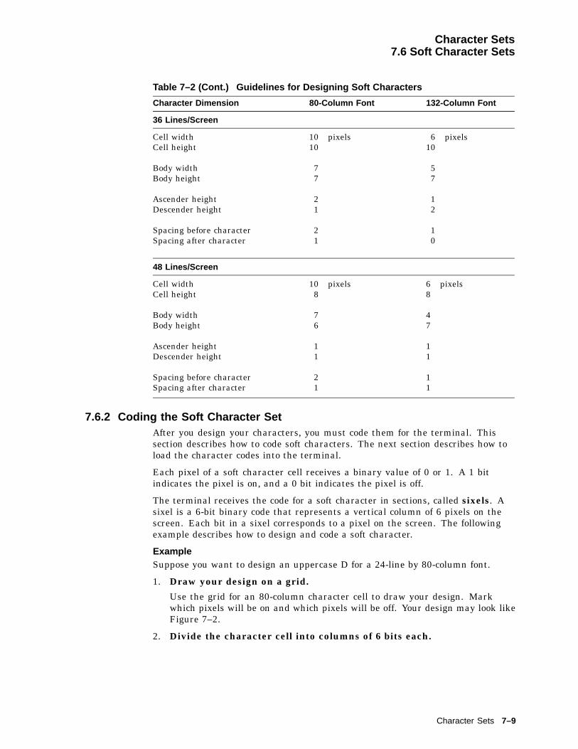
Character Sets7.6 Soft Character Sets
Table 7–2 (Cont.) Guidelines for Designing Soft Characters
Character Dimension 80-Column Font 132-Column Font
36 Lines/Screen
Cell width 10 pixels 6 pixelsCell height 10 10
Body width 7 5Body height 7 7
Ascender height 2 1Descender height 1 2
Spacing before character 2 1Spacing after character 1 0
48 Lines/Screen
Cell width 10 pixels 6 pixelsCell height 8 8
Body width 7 4Body height 6 7
Ascender height 1 1Descender height 1 1
Spacing before character 2 1Spacing after character 1 1
7.6.2 Coding the Soft Character SetAfter you design your characters, you must code them for the terminal. Thissection describes how to code soft characters. The next section describes how toload the character codes into the terminal.
Each pixel of a soft character cell receives a binary value of 0 or 1. A 1 bitindicates the pixel is on, and a 0 bit indicates the pixel is off.
The terminal receives the code for a soft character in sections, called sixels. Asixel is a 6-bit binary code that represents a vertical column of 6 pixels on thescreen. Each bit in a sixel corresponds to a pixel on the screen. The followingexample describes how to design and code a soft character.
ExampleSuppose you want to design an uppercase D for a 24-line by 80-column font.
1. Draw your design on a grid.
Use the grid for an 80-column character cell to draw your design. Markwhich pixels will be on and which pixels will be off. Your design may look likeFigure 7–2.
2. Divide the character cell into columns of 6 bits each.
Character Sets 7–9
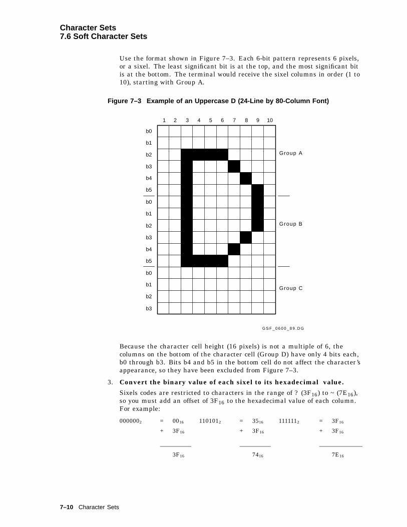
Character Sets7.6 Soft Character Sets
Use the format shown in Figure 7–3. Each 6-bit pattern represents 6 pixels,or a sixel. The least significant bit is at the top, and the most significant bitis at the bottom. The terminal would receive the sixel columns in order (1 to10), starting with Group A.
Figure 7–3 Example of an Uppercase D (24-Line by 80-Column Font)
G S F _ 0 6 0 0 _ 8 9 . D G
1 2 3 4 5 6 7 8 9 10
b0
b1
b2
b3
b4
b5
b0
b1
b2
b3
b4
b5
b0
b1
b2
b3
Group A
Group B
Group C
Because the character cell height (16 pixels) is not a multiple of 6, thecolumns on the bottom of the character cell (Group D) have only 4 bits each,b0 through b3. Bits b4 and b5 in the bottom cell do not affect the character’sappearance, so they have been excluded from Figure 7–3.
3. Convert the binary value of each sixel to its hexadecimal value.
Sixels codes are restricted to characters in the range of ? (3F16) to ~ (7E16),so you must add an offset of 3F16 to the hexadecimal value of each column.For example:
0000002 = 0016 1101012 = 3516 1111112 = 3F16
+ 3F16 + 3F16 + 3F16
3F16 7416 7E16
7–10 Character Sets

Character Sets7.6 Soft Character Sets
4. Use Table 7–3 to convert each binary number to the equivalent ASCIIcharacter.
Table 7–3 lists the results of steps 3 and 4 for each possible binary value. Allyou have to do is find the 6-digit binary number for each sixel bit pattern inyour character design.
Figure 7–4 shows this conversion for the uppercase D in this example.
You use this procedure to convert each character of your soft character set into astring of sixel bit patterns. Then you can download your DRCS characters intothe terminal, using the DECDLD device control string described in Chapter 5.
Table 7–3 Converting Binary Code to an ASCII Character
Binary Value Hex. ValueHex. Value + 3FOffset
CharacterEquivalent
000000 00 3F ?000001 01 40 @000010 02 41 A000011 03 42 B000100 04 43 C
000101 05 44 D000110 06 45 E000111 07 46 F001000 08 47 G001001 09 48 H
001010 A 49 I001011 B 4A J001100 C 4B K001101 D 4C L001110 E 4D M
001111 F 4E N010000 10 4F O010001 11 50 P010010 12 51 Q010011 13 52 R
010100 14 53 S010101 15 54 T010110 16 55 U010111 17 56 V011000 18 57 W
011001 19 58 X011010 1A 59 Y011011 1B 5A Z011100 1C 5B [011101 1D 5C \
011110 1E 5D ]011111 1F 5E ^100000 20 5F _
(continued on next page)
Character Sets 7–11

Character Sets7.6 Soft Character Sets
Table 7–3 (Cont.) Converting Binary Code to an ASCII Character
Binary Value Hex. ValueHex. Value + 3FOffset
CharacterEquivalent
100001 21 60 ‘100010 22 61 a
100011 23 62 b100100 24 63 c100101 25 64 d100110 26 65 e100111 27 66 f
101000 28 67 g101001 29 68 h101010 2A 69 i101011 2B 6A j101100 2C 6B k
101101 2D 6C l101110 2E 6D m101111 2F 6E n110000 30 6F o110001 31 70 p
110010 32 71 q110011 33 72 r100100 34 73 s110101 35 74 t110110 36 75 u
110111 37 76 v111000 38 77 w111001 39 78 x111010 3A 79 y111011 3B 7A z
111100 3C 7B {111101 3D 7C |111110 3E 7D }111111 3F 7E ~
7–12 Character Sets
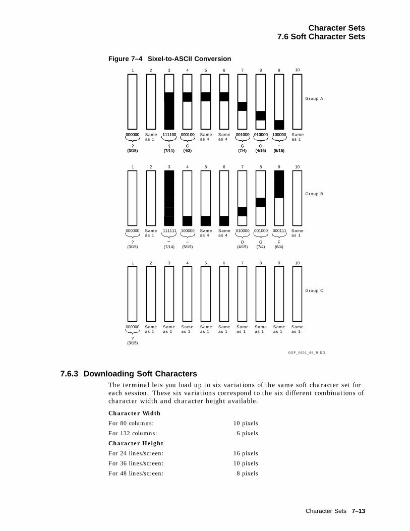
Character Sets7.6 Soft Character Sets
Figure 7–4 Sixel-to-ASCII Conversion
000000
?(3/15)
{(7/11)
111100 000100
C(4/3)
001000
G(7/4)
010000
O(4/15)
100000
_
(5/15)
000000
?(3/15) (7/14)
111111 100000
_
(5/15)
010000
O(4/15)
001000
G(7/4)
000111
F(6/4)
1 2 3 4 5 6 7 8 9 10
000000
?(3/15)
{(7/11)
111100 000100
C(4/3)
001000
G(7/4)
010000
O(4/15)
100000
(5/15)
000000
?(3/15)
1 2 3 4 5 6 7 8 9 10
G S F _ 0 6 0 1 _ 8 9 _ R . D G
1 2 3 4 5 6 7 8 9 10
~^M
Group A
Group B
Group C
Sameas 1
Sameas 4
Sameas 1
Sameas 1
Sameas 1
Sameas 1
Sameas 1
Sameas 1
Sameas 1
Sameas 1
Sameas 1
Sameas 1
Sameas 1
Sameas 1
Sameas 4
Sameas 4
Sameas 4
7.6.3 Downloading Soft CharactersThe terminal lets you load up to six variations of the same soft character set foreach session. These six variations correspond to the six different combinations ofcharacter width and character height available.
Character Width
For 80 columns: 10 pixels
For 132 columns: 6 pixels
Character Height
For 24 lines/screen: 16 pixels
For 36 lines/screen: 10 pixels
For 48 lines/screen: 8 pixels
Character Sets 7–13

Character Sets7.6 Soft Character Sets
You can adjust the screen size by using the select number of lines/screen(DECSNLS) control function. The terminal automatically selects the appropriatesoft set for the screen size.
When loading a soft set, you specify which of the six width/height variationsthe set is intended for. Your set replaces any soft set already loaded for thatwidth/height variation.
You should load six variations of your set to correspond to the six variationsof character width and height available in the terminal (80 or 132 columns by24, 36, or 48 lines). Do not confuse the font rendition with the actual characterset. You cannot load six different soft sets. However, you can load six differentrenditions of the same soft set.
7.6.4 Designating the Soft Character SetYou designate your soft character set the same way you designate the hardcharacter sets—using a select character set (SCS) sequence. You also use thesame format for the SCS sequence.
ESC1/11
Intermediate(s)*********
Final*****
Intermediate(s)are one or more characters that designate the soft character set as one of thelogical sets, G0 through G3. You use the same intermediate characters that youuse for SCS select character set function (Table 5–13).
The intermediate character(s) also indicates whether the soft character set isa 94- or 96-character set. Make sure you use an intermediate character thatmatches the setting of the character set size parameter (Pcss) in the DECDLDstring (Table 5–2).
Finalis the Dscs name you used for the soft character set in the DECDLD string.
Notes on Designating Soft Character Sets
• Replacing a soft set with a new soft set
If you use a new Dscs name when you replace the current soft set withanother soft set, then the following occurs:
– Characters from the old soft set are undefined. If you redefine the softset, characters currently on the screen may change.
– Any logical sets (G0, G1, G2, G3) used to designate the old soft set areundefined. The in-use table is also undefined.
After you load a new soft set, use a select character set (SCS) sequence todesignate the soft set. Using SCS eliminates the confusion involved withundefined characters.
• Replacing a hard set with a soft set
You can define a soft set that replaces one of the hard sets (such as ASCII orDEC Special Graphic).
7–14 Character Sets

Character Sets7.6 Soft Character Sets
A soft set that replaces a hard set remains in effect until you perform one ofthe following actions:
– Clear the soft set by:
• Recalling saved settings or factory-default settings with the Save orDefault fields in the Set-Up Directory.
• Running the power-up self-test.
– Redefine the soft set (using another DECDLD string).
7.6.5 Soft Character Set ExampleSuppose you want to create a soft character set containing a solid rectangle, ablank, a rectangular box, and a striped rectangle. You decide to use a font that is24 lines by 80 columns with a character cell size of 8 by 16 pixels. This exampleshows how you would
1. Download the set.
2. Designate the set as G1.
3. Map the G1 set into GL.
Note
Make sure the terminal is in a VT Level 4 or higher mode before you tryto load a soft character set. You cannot load soft sets in VT Level 1 mode.
1. You could use the following DECDLD string to load your character set. Thestring is shown divided into sections for clarity.
DCS1 ; 1 ; 0 ; 12 ; 1 ; 1 ; 12; 0 { sp @--------/--------/--------;????????/????????/????????;~@@@@@@~/~??????~/~GGGGGG~;TTTTTTTT/TTTTTTTT/TTTTTTTT;
ST
DCS (9/0)introduces the device control string.
1 ; 1 ; 0 ; 12 ; 1 ; 1 ; 12 ; 0is the parameter string specifying the following functions. See Table 5–2 forparameter definitions.
Parameter Function
Pfn = 1 Loads this soft set into the DRCS font buffer.
Pcn = 1 Selects the character at row 2/ column 1 in the ASCII table(Figure 4–1) as the first character to load.
Pe = 0 Erases all characters in the font buffer for that rendition.
Pcmw = 12 Selects a maximum character width of 12 pixels.
Pss = 1 Selects a font set size of 80 columns, 24 lines.
Pt = 1 Defines the set as a text font.
Pcmh = 12 Selects a maximum character height of 12 pixels.
Pcss = 0 Defines the set as a 94-character set.
Character Sets 7–15
Character Sets7.6 Soft Character Sets
{ (7/11)indicates the end of the parameter characters and specifies that this sequenceis a DECDLD string.
sp @defines the character set as an unregistered soft set. This value is therecommended default value for user-defined sets. The sp represents onespace. You can use other values to define other specific character sets.
——–/——–/——–represents the first character (a solid rectangle).
; separates the soft characters.
????????/????????/????????represents the second character (a blank).
~@@@@@@~/~??????~/~GGGGGG~represents the third character (a hollow rectangle).
TTTTTTTT/TTTTTTTT/TTTTTTTTrepresents the fourth character (a set of horizontal stripes).
ST (9/12) indicates the end of the DECDLD string.
2. Now you are ready to designate the character set as G1. You can use thefollowing SCS escape sequence:
ESC ) sp @
ESC (1/11) introduces the SCS sequence.
) (2/9)designates the character set as G1.
sp @ (2/0, 4/0)selects the soft set as the set to designate as G1. Remember, sp @ was thename used for the soft set in the DECDLD string.
3. Finally, you want to map the G1 set into the in-use table as GL. You can mapthe set by sending a shift out (SO) control character. To send (load) the SOcharacter, you hold down the Ctrl key and press the N key.
Note
For information on using shift characters, see LS-Locking Shift orSS-Single Shift commands.
7.6.6 Clearing a Soft Character SetYou can clear a soft character set that you loaded into the terminal by using thefollowing DECDLD control string:
DCS 1;1;2 { sp @ ST
Any of the following actions also clear the soft character set:
• Performing the power-up self-test.
• Selecting the Recall or Default set-up fields from the Set-Up Directory.
• Using a reset to initial state (RIS) sequence.
7–16 Character Sets

8Keyboard Processing
This chapter describes the physical keyboards and keyboard-to-host interfacesupported by the VT520 video terminal.
8.1 Overview—Keyboard LayoutThe term keyboard layout describes the physical layout of a keyboard,specifically, the number of keys and their positions on the keyboard. The VT520supports two keyboard layouts: VT layout and PC layout.
Figure 8–1 VT Keyboard Layout
X
Z X C V B N
A S D F G H J K L
I O PT Y UW E R
M
Q
1 2 3 4 5 6 7 8 9 0! # $ % ^ & * ( )a
><
Return
Shift?/.,
:; "
’|\
}]
-- +
=
}]
Help Do
Prev Next
Re-move
InsertHere
Find
Select
PF1 PF2 PF3
Enter
54
7 8 9 _
,6
321
0 .
PF4~
Ctrl
Tab
Shift
AltFunction
ComposeCharacter
AltFunction
ComposeCharacter
F1 F2 F3 F4 F5 F6 F7 F8 F9 F10 F11 F12 F13 F14 F17 F18 F19 F20
(ESC)
North American/United Kingdom (Word Processing Version)
><
MA-1520a-92.PS
Figure 8–2 PC Keyboard Layout
PageUp
HomeInsert
Esc F1 F2 F3 F4 F5 F6 F7 F8 F9 F10 F11 F12 PrintScreen
ScrollLock
SetUp Break
Pause
PageDown
EndDelete
BackSpace1 2 3 4 5 6 7 8 9 0! # $ % ^ & * ( )a
- +=
~
Z X C V B N
A S D F G H J K L
I O PT Y UW E R
M
Q
?/.,
:; "
’
}]
Caps
Tab
Shift ><
Ctrl Ctrl
_
Home PgUp
_/
PgDnEnd
Ins Del
NumLock
7 8 9
4 5 6
321
0 .
+
Enter
*
G S F - M K 2 5 1 0 - 2 9 - D G
North American
Num Lock Caps Lock Scroll Lock
Alt Alt l
LJ-00226a-TI0.PS
LockEnter
|\
}]
Shift
d i ig t a l
Keyboard Processing 8–1

Keyboard Processing8.2 DEC VT Layout
8.2 DEC VT LayoutWhen a DEC VT Layout keyboard is used, only characters from the currentlyselected keyboard character set may be generated. All other graphic characterkeystrokes are ignored. See Chapter 8 for a list of the character sets supported.
The numeric keypad compose feature works as follows. Pressing and holdingthe Compose (Alt-Gr on EPC keyboards) while typing a number on the numerickeypad sends the corresponding decimal character code. The character code willbe sent when the Compose key is release. If the keypad period is typed whileentering the number, the previously entered value is multiplied by 16 and addedto the value entered subsequently. This feature supports the column/row entryused commonly in character coding tables.
8.3 VT Layout - PC Term ModePCTerm mode using a VT layout keyboard is the same as PCTerm mode with anEnhanced PC layout keyboard with the following exceptions:
• All keystrokes send scan codes, except:
CapsLock F1 performs Hold,
CapsLock F2 forms Print,
CapsLock F3 enters Set-Up, and
CapsLock F5 send Break.
• Keystations 107, 124 - 126, and 130 send the corresponding scan codesgenerated by the LK411 VT layout. Keystations 131 - 133 act as Print Screen,Scroll Lock, and Pause.
• Keystations 42, (VT \ | ), sends the scan code of keystation 29 of EnhancedPC layout (EPC \ | ).
• Keystations 127 (VT Do ), sends the scan code of keystation 110 (EPC Esc ).
Table 8–1 shows the make/break scan codes for the VT layout in PCTerm mode.
Table 8–1 Scan Codes for VT Layout in PCTerm Mode
Key No. VT Legend (U.S.) Scan Code (Make / Break)
42 \ | 2B/AB
107 KP, 7E / FE
124 F13 E0 3D / E0 BD
125 F14 E0 3E / E0 BE
126 Help E0 3F / E0 BF
127 Do 01 / 81
130 F17 E0 41 / E0 C1
131 PrtSc E0 2A E0 37 / E0 B7 E0 AACtrl or Shift 37 / E0 B7 E0 AA
131 SysReq Alt 54 / D4
132 Scroll Lock 46 / C6
133 Pause E1 1D 45 E1 9D C5
Break Ctrl E0 46 E0 C6
8–2 Keyboard Processing
Keyboard Processing8.4 Enhanced PC Layout - PCTerm Mode
8.4 Enhanced PC Layout - PCTerm ModeIn PCTerm mode, each press or release keystroke causes a unique scan code orsequence of scan codes to be sent to the host, corresponding to the keystation thatwas pressed or released. There is no keyboard character set. It is left to the hostto translate scan codes into the desired display character set.
The one exception to the rule above is that Caps Lock combinations that involvelocal functions still work.
• CapsLock Print Screen enters Set-Up,
• CapsLock Pause send Break,
• CapsLock F1 performs Hold,
• CapsLock F2 forms Print,
• CapsLock F3 enters Set-Up, and
• CapsLock F5 send Break.
The make code for Caps Lock is sent when the Caps Lock key is released, beforeanother key is pressed, or when another key is pressed that is not defined as alocal function above.
All keys, including Shift , Alt , and Ctrl send make codes immediately upon beingdepressed, EXCEPT Caps Lock , whose make code is deferred as described above.If a modifier combination other than CapsLock is defined to invoke a localfunction (such as Alt/F3), a make code is sent for the modifier before the localfunction is invoked. When the local function is recognized, the correspondingbreak code is sent to cancel the modifier.
DEC and ISO multinational character sets are available in PCTerm mode. The7-bit NRC sets are not included.
8.5 Enhanced PC Layout - VT ModeThe Enhanced PC layout can be used as an alternate to the VT Layout in VTmode. In this mode, the VT520 still operates as a traditional video terminal tocommunicate with conventional terminal applications. Since the Enhanced PCLayout does not correspond key-for-key to the VT Layout, some adaptation isnecessary. Two styles are provided to support different users:
• DEC VT Style for traditional DEC VT users.
• IBM PC Style for IBM PC or ASCII terminal users
Pressing Caps Lock Num Lock toggles between these two styles. When DEC VTStyle is selected, ‘‘VT’’ is displayed on the keyboard indicator line. Either stylecan be saved in NVM.
8.5.1 DEC VT StyleIn this style, all keys send the same function sequences as the similarly namedkey on the VT Layout. The missing keys from the VT Layout are accessed byCaps Lock key combinations, where you press and hold Caps Lock while you typeanother key.
• Local terminal functions, ‘‘Print Screen,’’ ‘‘Scroll Lock,’’ and ‘‘Pause,’’ are toprow F keys.
• Left Alt/Space functions as compose key.
Keyboard Processing 8–3

Keyboard Processing8.5 Enhanced PC Layout - VT Mode
8.5.2 IBM PC StyleIn this style (the default style), the keys are mapped to behave as they would onan IBM PC. The differences in the IBM PC Style are:
• Editing keypad keys, Home and Delete , send sequences corresponding to thesefunctions.
• Numeric keypad keys send different sequences when the keypad is in numericmode to accommodate the ‘‘Num Lock’’ feature. With Num Lock off, thenumeric keypad sends editing key sequences.
• F1 through F5 send function key sequences in PC style. Local terminalfunctions, ‘‘Print Screen,’’ ‘‘Scroll Lock,’’ and ‘‘Pause,’’ are located as theywould be on an Enhanced PC layout.
• Keys to operate copy and paste are different. See 3.7.
• Left Alt/Space does not work as compose key.
8.6 Main Key ArrayThis section describes the main keys on the keyboard.
8.6.1 Character SetsOnly characters from the currently selected keyboard character set may begenerated. All other graphic character keystrokes are ignored. The followingkeyboard character sets are supported: ISO Latin 1, ISO Latin 2, ISO LatinCyrillic, ISO Latin Greek, ISO Latin Hebrew, ISO Latin 5 (Turkish), DECMultinational, DEC Cyrillic, DEC Greek, DEC Hebrew and DEC Turkish. When7-bit NRCS characters is selected, a corresponding 7-bit NRC set is supportedbased on the Keyboard Dialect.
PC character sets are not supported in VT modes since the terminal is being usedas a conventional video terminal that happens to have a PC keyboard attached.New applications should be written to use ISO character sets. (PC character setsare available in PCTerm and SCO console mode.)
Characters corresponding to the right side of the key top are typed by pressingthe key in combination with Alt Gr , the right Alt key.
8.6.2 Tab KeyWith an Enhanced PC Layout keyboard, pressing Shift/Tab causes a CBT sequence,CSI Z, to be transmitted. A horizontal tabulation code (HT, 0/9) is transmittedwhen a VT Layout keyboard is used.
8.6.3 Modifier KeysTable 8–2 shows the corresponding modifier keys for the VT and the EnhancedPC layouts.
8–4 Keyboard Processing

Keyboard Processing8.6 Main Key Array
Table 8–2 VT Style Layout vs. Enhanced PC Style Layout Modifier Keys
VT Style Keyboard PC Style Keyboard
Left Shift Left Shift
Right Shift Right Shift
Caps Lock Caps Lock
Ctrl Left Ctrl
none Right Ctrl
Left Compose character Alt Gr
Right Compose character none
Left Alt Left Alt
Right Alt none or Right Alt
There is no Ctrl key on the right side of the VT keyboard. Left and right Ctrl keyson the Enhanced PC layout generates the single control function the same as onthe VT Layout.
There is no key labeled "compose" on the Enhanced PC layout. Alt Gr (RightAlt) accesses the supplemental characters on the top right half of the key tops onsome Enhanced PC layout keyboards. Alt Gr can be used with the numeric keypadto enter character codes directly. Left Alt Space can be used to initiate composesequences when VT Style is selected.
8.6.4 Caps LockThe Lock function may operate in three ways:
Caps Lock Alphabetic keys send their shifted character.
Shift Lock All keys on the main key array send their shifted character.
Reverse Lock Pressing Shift temporarily reverses the effect of Caps Lock ; that is,unshifted or lowercase alphabetic characters are transmitted.
Pressing and releasing the Caps Lock key toggles the lock state on or off.
The Caps Lock key is also used to generate keystrokes for keys that are notpresent on the keyboard. Known as keyboard extension, this is done by pressingand holding the Caps Lock key and then pressing the extension key. The lockstate is not toggled when an extension keystroke is pressed. The followingExtension keystrokes are defined:
• Caps Lock Print Screen acts as the Set-Up key.
• Caps Lock Pause acts as the Break key.
• Caps Lock F1— Caps Lock F10 on the Enhanced PC Layout generates F11—F20.Caps Lock KP+ acts as KP- (DEC keypad minus) in application mode.
8.6.5 Left AltLeft Alt on the PC layout corresponds to the Alt function on the VT layout.Depressing the left Alt key performs the following functions (unless re-programmed):
• Left Alt Space acts as the compose key in VT Style.
Keyboard Processing 8–5
Keyboard Processing8.6 Main Key Array
• On the United States Enhanced PC layout, the left Alt acts the same as Alt Gr
when pressed and held in combination with keys from the numeric keypad.This feature keeps the two Alt keys equivalent to each other.
8.6.6 Right AltThe right Alt key appears on the United States Enhanced PC layout. On othercountry layouts, the right Alt key appears as Alt Gr . Depressing the right Alt keyperforms the following functions (unless re-programmed):
• Right Alt Space acts as the compose key in VT Style. This feature keeps thetwo Alt keys equivalent.
• Right Alt key acts the same as the Alt Gr key when pressed and held incombination with keys from the numeric keypad.
• The right Alt key is the same as the Right Alt function on the VT layout withthe exceptions listed previously.
8.6.7 Alt GrThe right Alt key is marked as Alt Gr on all but the United States Enhanced PClayout. The words Alt Gr are short for alternate graphic and corresponds roughlyto the function of the compose key.
• Alt Gr in combination with graphic character keys generate the charactercorresponding to the right side of the key tops.
• Alt Gr is used for numeric keypad compose.
8.7 Top Row Function KeysThere are 20 top row function keys on the VT layout and 12 on the EnhancedPC layout. Caps Lock/F1 through Caps Lock/F10 keys on the Enhanced PClayout transmit the same sequences as F11 through F20 in the VT layout.Additional unique function sequences are transmitted by pressing function keysin combination with Shift , Alt , or Ctrl keys. See DECFNK and DECPAK for details.
In VT Style, the F1 through F5 keys operate the same as on the VT layoutand can be used for local functions to send function sequences or to be ignored.In VT Style, F13 (Print Screen), F14 (Scroll Lock), and F15 (Pause) send theircorresponding function key sequences. In PC Style, the F1 through F5 keyssend function sequences (unless re-programmed) while Print Screen , Scroll Lock ,and Pause default to local functions.
8.8 Editing Keypad KeysFigure 8–3 shows the layout for the DEC VT and Enhanced PC editing keypads.
8–6 Keyboard Processing

Keyboard Processing8.8 Editing Keypad Keys
Figure 8–3 Editing Keypad Legends on DEC and PC Layouts
DEC VT Layout Enhanced PC Layout
Find Insert Here
Select Prev Next
Insert
Delete
Home
End
PageUp
PageDown
Re−Move
MA−0028−93.GRA
When DEC VT Style is selected, the Enhanced PC layout editing keys transmitthe same function sequences as the similarly legend editing keys in the VTlayout. In IBM PC Style, the Home key sends a Cursor Up (CUP) sequence tomove the cursor home and the Delete key transmits a DEL (7/15).
Table 8–3 lists the key sequences for Enhanced PC editing keypads.
Table 8–3 Editing Keypad Sequences for Enhanced PC Layout
Enhanced PC Legend VT LegendVT StyleSequence
PC StyleSequence
Insert Insert Here CSI 2 ~ CSI 2 ~
Delete Remove CSI 3 ~ DEL
Home Find CSI 1 ~ CSI H
End Select CSI 4 ~ CSI 4 ~
Page Up Prev Screen CSI 5 ~ CSI 5 ~
Page Down Next Screen CSI 6 ~ CSI 6 ~
In addition to these unshifted sequences, the editing keys can send uniquesequences when pressed in combination with Shift , Alt , or Ctrl . See DECFNK fordetails.
8.9 Cursor Keypad KeysThe cursor keypad keys send the same sequences as the VT layout. Additionalunique sequences can be sent when pressed in combination with Shift , Alt , or Ctrl .See DECFNK for details.
8.10 Numeric Keypad KeysThe Enhanced PC layout numeric keypad has three differences from the VTlayout:
1. The four keys at the top of the keyboard are labeled Num Lock , / , * , and -
instead of PF1 through PF4 .
2. The Num Lock key toggles the keypad keys, sending either numerals orfunction sequences.
3. A two unit + key occupies the - and , positions so there is no keypadcomma.
Keyboard Processing 8–7
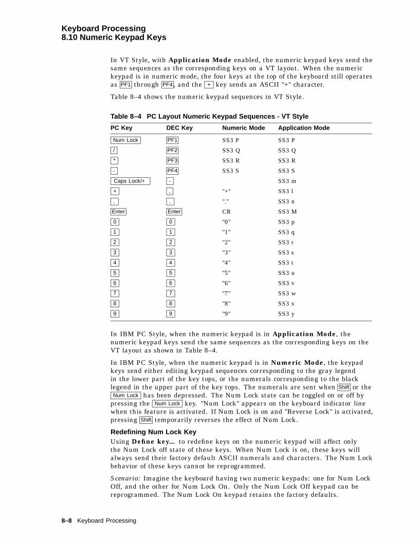
Keyboard Processing8.10 Numeric Keypad Keys
In VT Style, with Application Mode enabled, the numeric keypad keys send thesame sequences as the corresponding keys on a VT layout. When the numerickeypad is in numeric mode, the four keys at the top of the keyboard still operatesas PF1 through PF4 , and the + key sends an ASCII "+" character.
Table 8–4 shows the numeric keypad sequences in VT Style.
Table 8–4 PC Layout Numeric Keypad Sequences - VT Style
PC Key DEC Key Numeric Mode Application Mode
Num Lock PF1 SS3 P SS3 P
/ PF2 SS3 Q SS3 Q
* PF3 SS3 R SS3 R
- PF4 SS3 S SS3 S
Caps Lock/+ - SS3 m
+ , "+" SS3 l
. . "." SS3 n
Enter Enter CR SS3 M
0 0 "0" SS3 p
1 1 "1" SS3 q
2 2 "2" SS3 r
3 3 "3" SS3 s
4 4 "4" SS3 t
5 5 "5" SS3 u
6 6 "6" SS3 v
7 7 "7" SS3 w
8 8 "8" SS3 x
9 9 "9" SS3 y
In IBM PC Style, when the numeric keypad is in Application Mode, thenumeric keypad keys send the same sequences as the corresponding keys on theVT layout as shown in Table 8–4.
In IBM PC Style, when the numeric keypad is in Numeric Mode, the keypadkeys send either editing keypad sequences corresponding to the gray legendin the lower part of the key tops, or the numerals corresponding to the blacklegend in the upper part of the key tops. The numerals are sent when Shift or theNum Lock has been depressed. The Num Lock state can be toggled on or off by
pressing the Num Lock key. "Num Lock" appears on the keyboard indicator linewhen this feature is activated. If Num Lock is on and "Reverse Lock" is activated,pressing Shift temporarily reverses the effect of Num Lock.
Redefining Num Lock KeyUsing Define key... to redefine keys on the numeric keypad will affect onlythe Num Lock off state of these keys. When Num Lock is on, these keys willalways send their factory default ASCII numerals and characters. The Num Lockbehavior of these keys cannot be reprogrammed.
Scenario: Imagine the keyboard having two numeric keypads: one for Num LockOff, and the other for Num Lock On. Only the Num Lock Off keypad can bereprogrammed. The Num Lock On keypad retains the factory defaults.
8–8 Keyboard Processing

Keyboard Processing8.10 Numeric Keypad Keys
Table 8–5 lists the numeric keypad sequences in PC Style Numeric mode.
Table 8–5 PC Layout Numeric Keypad Sequences - PC Style, Numeric Mode
KeysNum Lock Off unshifted, orNum Lock On with Shift
Num Lock On unshifted, orNum Lock Off with Shift
Num Lock
/ / /
* * *
- - -
+ + +:
DelDEL .
Enter CR CR0
InsCSI 2 ~ 0
1End
CSI 4 ~ 12+ CSI B 2
3PgDn CSI 6 ~ 34( CSI D 4
5 56) CSI C 6
7Home
CSI H 78* CSI A 8
9PgUp CSI 5 ~ 9
Several of the Enhanced PC layout keyboards use a comma instead of a period onkey 104, sending the corresponding code for a comma instead of a period shownin Table 8–5.
8.11 Local Function Key DefaultsThe keys used to perform local terminal functions differ between the VTkeyboard, PC keyboard, and the mode selection. Table 8–6 shows thecorresponding keys for the default local functions. The function number inTable 8–6 is used in the DECPFK host sequence or DECPAK’s alternate functionto specify a change to that local function key.
Table 8–6 Local Functions
FunctionNumber Function
VTKeyboard
SCOConsole
PC KeyboardVT-Style
PCKeyboardPC-Style
PCKeyboardSCO
0 no function
1 Hold F1 CapsLk/F1 F1 Scroll Lock
± means the function switches alternately between on and off.C&P means Copy and Paste.CapsLk means the Lock key, Caps Lock key, or key with lock icon.
(continued on next page)
Keyboard Processing 8–9

Keyboard Processing8.11 Local Function Key Defaults
Table 8–6 (Cont.) Local Functions
FunctionNumber Function
VTKeyboard
SCOConsole
PC KeyboardVT-Style
PCKeyboardPC-Style
PCKeyboardSCO
2 Print F2 CapsLk/F2 F2 Print Screen
3 Set-Up F3 CapsLk/F3 F3 CapsLk/Print Screen
CapsLk/Sys Rqor
Alt/Print Screen
4 Session Forward F4 , CapsLk KP0 F4 , CapsLk KP0 F4 , CapsLk KP0
5 Break F5 CapsLk/F5 F5 CapsLk/Pause
7 Hard Reset Ctrl/F3 CapsLk/Ctrl/F3 Ctrl/F3 Ctrl/CapsLk/Print Screen
8 Toggle Autoprint Ctrl/F2 CapsLk/Ctrl/F2 Ctrl/F2 Ctrl/Print Screen
9 Disconnect Shift/F5 CapsLk/Shift/F5 Shift/F5 Shift/CapsLk/Pause
10 Send Answerback Ctrl/F5 CapsLk/Ctrl/F5 Ctrl/F5 Ctrl/CapsLk/Pause
11 Print ComposedMain Display
Shift/F2 n/a4 Shift/F2 Shift/Print Screen n/a
12 Session Backward Shift F4 ,Shift CapsLk KP0
Shift F4 ,Shift CapsLk KP0
Shift F4 ,Shift CapsLk KP0
20 Pan Up Ctrl/ * n/a Ctrl/ * Ctrl/ * n/a
21 Pan Down Ctrl/ + n/a Ctrl/ + Ctrl/ +
24 Pan Prev Page Ctrl/Prev n/a Ctrl/Page Up Ctrl/Page Up
25 Pan Next Page Ctrl/Next n/a Ctrl Page Down Ctrl/Page Down
30 Copy & PasteMode
F1 (holddown)
CapsLk/F1 F1 Scroll Lock
31 C&P Cursor Left ( ( (
32 C&P CursorDown
+ + +
33 C&P Cursor Up * * *
34 C&P CursorRight
) ) )
35 C&P StartSelection
Select Home Home
36 C&P Copy Remove End End
37 C&P Paste Insert Here Insert Insert
38 C&P ±Left-to-Right
Select Home Home
41 Shift Modifier Left or rightShift
Left or rightShift
Left or rightShift
4 n/a means the function is not available in the default SCO state. If there is no "n/a" in the SCO Console column, thenthis means that the key sequence is the same as the VT Keyboard column. If there is no "n/a" in the PC KeyboardSCO column, then this means that the key sequence is the same as the PC Keyboard PC-Style column.± means the function switches alternately between on and off.C&P means Copy and Paste.CapsLk means the Lock key, Caps Lock key, or key with lock icon.
(continued on next page)
8–10 Keyboard Processing
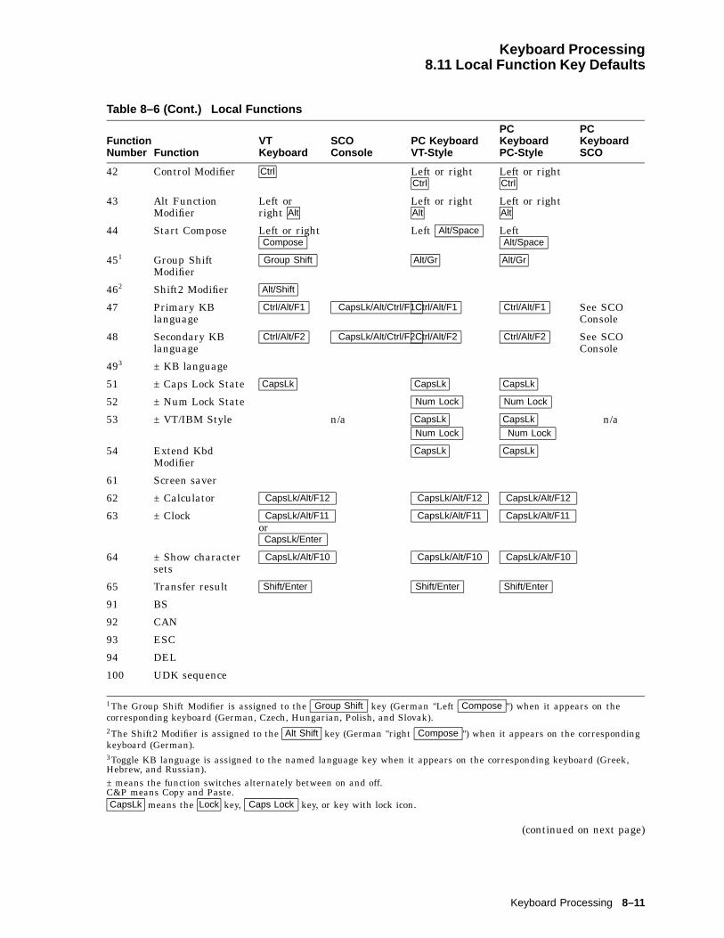
Keyboard Processing8.11 Local Function Key Defaults
Table 8–6 (Cont.) Local Functions
FunctionNumber Function
VTKeyboard
SCOConsole
PC KeyboardVT-Style
PCKeyboardPC-Style
PCKeyboardSCO
42 Control Modifier Ctrl Left or rightCtrl
Left or rightCtrl
43 Alt FunctionModifier
Left orright Alt
Left or rightAlt
Left or rightAlt
44 Start Compose Left or rightCompose
Left Alt/Space LeftAlt/Space
451 Group ShiftModifier
Group Shift Alt/Gr Alt/Gr
462 Shift2 Modifier Alt/Shift
47 Primary KBlanguage
Ctrl/Alt/F1 CapsLk/Alt/Ctrl/F1Ctrl/Alt/F1 Ctrl/Alt/F1 See SCOConsole
48 Secondary KBlanguage
Ctrl/Alt/F2 CapsLk/Alt/Ctrl/F2Ctrl/Alt/F2 Ctrl/Alt/F2 See SCOConsole
493 ± KB language
51 ± Caps Lock State CapsLk CapsLk CapsLk
52 ± Num Lock State Num Lock Num Lock
53 ± VT/IBM Style n/a CapsLk
Num Lock
CapsLk
Num Lockn/a
54 Extend KbdModifier
CapsLk CapsLk
61 Screen saver
62 ± Calculator CapsLk/Alt/F12 CapsLk/Alt/F12 CapsLk/Alt/F12
63 ± Clock CapsLk/Alt/F11or
CapsLk/Enter
CapsLk/Alt/F11 CapsLk/Alt/F11
64 ± Show charactersets
CapsLk/Alt/F10 CapsLk/Alt/F10 CapsLk/Alt/F10
65 Transfer result Shift/Enter Shift/Enter Shift/Enter
91 BS
92 CAN
93 ESC
94 DEL
100 UDK sequence
1The Group Shift Modifier is assigned to the Group Shift key (German "Left Compose ") when it appears on thecorresponding keyboard (German, Czech, Hungarian, Polish, and Slovak).2The Shift2 Modifier is assigned to the Alt Shift key (German "right Compose ") when it appears on the correspondingkeyboard (German).3Toggle KB language is assigned to the named language key when it appears on the corresponding keyboard (Greek,Hebrew, and Russian).± means the function switches alternately between on and off.C&P means Copy and Paste.CapsLk means the Lock key, Caps Lock key, or key with lock icon.
(continued on next page)
Keyboard Processing 8–11

Keyboard Processing8.11 Local Function Key Defaults
Table 8–6 (Cont.) Local Functions
FunctionNumber Function
VTKeyboard
SCOConsole
PC KeyboardVT-Style
PCKeyboardPC-Style
PCKeyboardSCO
105 Soft reset (WY)5 Shift F3 Shift F3 Shift F3
106 ±Show controls Shift Ctrl KP1 Shift Ctrl KP1 Shift Ctrl KP1
111 ±Status display(WY)
Ctrl ( Ctrl ( Ctrl (
112 ±Split screen
113 Raise page split(WY)
Ctrl KP - Ctrl KP - Ctrl KP -
114 Lower page split(WY)
Ctrl KP + Ctrl KP + Ctrl KP +
115 Adjust window toshow cursor (WY)
Ctrl Find Ctrl Find Ctrl Home
116 ±Cursor drag(WY)
Ctrl Shift KP ’
117 ±Insert mode(WY)
Ctrl PF4
Ctrl Shift PF4
Ctrl PF4
Ctrl Shift Insert
Ctrl PF4
Ctrl Shift Insert
119 Home & Clear(WY)
Ctrl Shift Prev Ctrl Shift Home
120 Page 0 (WYmono)
Ctrl KP0 Ctrl KP0 Ctrl KP0
121 Page 1 (WYmono)
Ctrl KP1 Ctrl KP1 Ctrl KP1
122 Page 2 (WYmono)
Ctrl KP2 Ctrl KP2 Ctrl KP2
123 Page 3 (WYmono)
Ctrl KP3 Ctrl KP3 Ctrl KP3
124 Page 4 (WYmono)
Ctrl KP4 Ctrl KP4 Ctrl KP4
125 Page 5 (WYmono)
Ctrl KP5 Ctrl KP5 Ctrl KP5
126 Page 6 (WYmono)
Ctrl KP6 Ctrl KP6 Ctrl KP6
127 Page 7 (WYmono)
Ctrl KP7 Ctrl KP7 Ctrl KP7
128 Page 8 (WYmono)
Ctrl KP8 Ctrl KP8 Ctrl KP8
129 Page 9 (WYmono)
Ctrl KP9 Ctrl KP9 Ctrl KP9
138 Prev Page Ctrl Prev
Ctrl Shift Prev
Ctrl PageUp
Ctrl Shift PageUp
5(WY) indicates that this function is available in the ASCII emulation modes only. ‘‘WY color’’ indicates that this functionis available only in the WYSE color emulation mode. ‘‘WY mode’’, only in the WYSE mono emulation mode.± means the function switches alternately between on and off.C&P means Copy and Paste.CapsLk means the Lock key, Caps Lock key, or key with lock icon.
(continued on next page)
8–12 Keyboard Processing

Keyboard Processing8.11 Local Function Key Defaults
Table 8–6 (Cont.) Local Functions
FunctionNumber Function
VTKeyboard
SCOConsole
PC KeyboardVT-Style
PCKeyboardPC-Style
PCKeyboardSCO
139 Next Page Ctrl Next
Ctrl Shift Next
Ctrl PageDn
Ctrl Shift PageDn
142 Slow Scroll Ctrl Shift + Ctrl Shift +
143 Fast Scroll Ctrl Shift * Ctrl Shift *
151 ±Keyclick Shift Enter Shift Enter
155 ±Block mode(WY)
Shift Ctrl F5
or F4
Shift Ctrl Pause Shift Ctrl Pause
156 Block mode on(WY scan mode)
Alt PF1 Alt NumLock Alt NumLock
157 Block mode off(WY scan mode)
F4 Pause Pause
159 Palette soft(WY325)5
Ctrl KP . Ctrl KP . Ctrl KP .
160 Palette 0 (WYcolor)
Ctrl KP0 Ctrl KP0 Ctrl KP0
161 Palette 1 (WYcolor)
Ctrl KP1 Ctrl KP1 Ctrl KP1
162 Palette 2 (WYcolor)
Ctrl KP2 Ctrl KP2 Ctrl KP2
163 Palette 3 (WYcolor)
Ctrl KP3 Ctrl KP3 Ctrl KP3
164 Palette 4 (WYcolor)
Ctrl KP4 Ctrl KP4 Ctrl KP4
165 Palette 5 (WYcolor)
Ctrl KP5 Ctrl KP5 Ctrl KP5
166 Palette 6 (WYcolor)
Ctrl KP6 Ctrl KP6 Ctrl KP6
167 Palette 7 (WYcolor)
Ctrl KP7 Ctrl KP7 Ctrl KP7
168 Palette 8 (WYcolor)
Ctrl KP8 Ctrl KP8 Ctrl KP8
169 Palette 9 (WYcolor)
Ctrl KP9 Ctrl KP9 Ctrl KP9
170 ± Framedwindows
171 ± Windowconfiguration
Ctrl F4
Ctrl CapsLk KP0
Ctrl F4
Ctrl CapsLk KP0
Ctrl F4
Ctrl CapsLk KP0
172 Raise windowborder
Ctrl Shift * Ctrl Shift * Ctrl Shift *
5(WY) indicates that this function is available in the ASCII emulation modes only. ‘‘WY color’’ indicates that this functionis available only in the WYSE color emulation mode. ‘‘WY mode’’, only in the WYSE mono emulation mode.± means the function switches alternately between on and off.C&P means Copy and Paste.CapsLk means the Lock key, Caps Lock key, or key with lock icon.
(continued on next page)
Keyboard Processing 8–13

Keyboard Processing8.11 Local Function Key Defaults
Table 8–6 (Cont.) Local Functions
FunctionNumber Function
VTKeyboard
SCOConsole
PC KeyboardVT-Style
PCKeyboardPC-Style
PCKeyboardSCO
173 Lower windowborder
Ctrl Shift + Ctrl Shift + Ctrl Shift +
181 Session 1 CapsLk KP1 CapsLk KP1 CapsLk KP1
182 Session 2 CapsLk KP2 CapsLk KP2 CapsLk KP2
183 Session 3 CapsLk KP3 CapsLk KP3 CapsLk KP3
184 Session 4 CapsLk KP4 CapsLk KP4 CapsLk KP4
± means the function switches alternately between on and off.C&P means Copy and Paste.CapsLk means the Lock key, Caps Lock key, or key with lock icon.
Note
See Chapter 2 to re-define keys using the Define Key Editor.
8.11.1 Numeric Keypad ComposePressing and holding Compose , Alt or Alt Gr while typing a decimal number onthe numeric keypad sends the corresponding decimal character code when thecompose key is released. If the . key on the keyboard is pressed while enteringa number, then the value entered before pressing the . key is multiplied by 16and added to the value entered next. This supports column/row entry commonlyused in character coding tables.
8–14 Keyboard Processing

Keyboard Processing8.11 Local Function Key Defaults
8.11.2 Accessibility AidsAccessibility aids allow the user with limited motor skills to use modifierkey combinations in a sequential manner rather than a simultaneous manner(default). All modifier key combinations are supported.
The Accessibility aids option is enabled by depressing the Shift key five times insuccession. This option can be disabled by pressing and holding a modifier keywhile pressing another key.
Once enabled, this option provides two levels of assistance known as Latch andLock. The Latch state is achieved by pressing a modifier key once and affects thenext key pressed. The Lock state is achieved by pressing a modifier key twice.All keys pressed are affected by the modifier until they are unlocked by eitherdepressing the modifier key again or depressing another modifier key twice. Onceany modifier is in the Locked state, pressing other modifier keys adds thosemodifiers to the Locked state.
A small icon appears on the Keyboard Indicator Line or Status Line to provideuser feedback on the changing modifier state.
The icons for each state are as follows:
Accessibility Aid Keys Enabled
Modifier Latched (Cleared on Next Keystroke)
Modifier Locked
When Accessibility aid keys are disabled, no icon is displayed on the KeyboardIndicator Line or Status Line.
Keyboard Processing 8–15
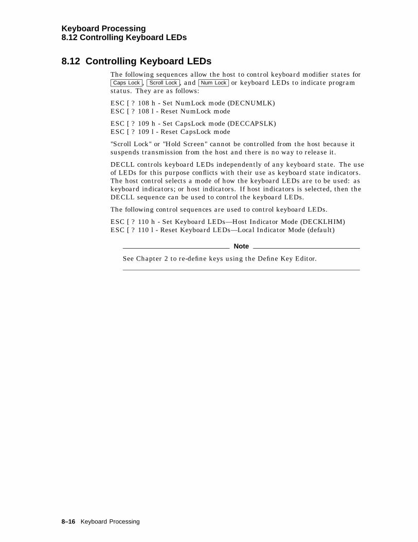
Keyboard Processing8.12 Controlling Keyboard LEDs
8.12 Controlling Keyboard LEDsThe following sequences allow the host to control keyboard modifier states forCaps Lock , Scroll Lock , and Num Lock or keyboard LEDs to indicate program
status. They are as follows:
ESC [ ? 108 h - Set NumLock mode (DECNUMLK)ESC [ ? 108 l - Reset NumLock mode
ESC [ ? 109 h - Set CapsLock mode (DECCAPSLK)ESC [ ? 109 l - Reset CapsLock mode
"Scroll Lock" or "Hold Screen" cannot be controlled from the host because itsuspends transmission from the host and there is no way to release it.
DECLL controls keyboard LEDs independently of any keyboard state. The useof LEDs for this purpose conflicts with their use as keyboard state indicators.The host control selects a mode of how the keyboard LEDs are to be used: askeyboard indicators; or host indicators. If host indicators is selected, then theDECLL sequence can be used to control the keyboard LEDs.
The following control sequences are used to control keyboard LEDs.
ESC [ ? 110 h - Set Keyboard LEDs—Host Indicator Mode (DECKLHIM)ESC [ ? 110 l - Reset Keyboard LEDs—Local Indicator Mode (default)
Note
See Chapter 2 to re-define keys using the Define Key Editor.
8–16 Keyboard Processing
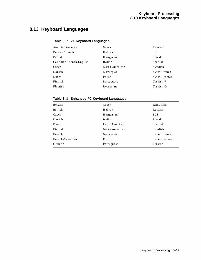
Keyboard Processing8.13 Keyboard Languages
8.13 Keyboard Languages
Table 8–7 VT Keyboard Languages
Austrian/German Greek Russian
Belgian/French Hebrew SCS
British Hungarian Slovak
Canadian-French/English Italian Spanish
Czech North American Swedish
Danish Norwegian Swiss-French
Dutch Polish Swiss-German
Finnish Portuguese Turkish F
Flemish Romanian Turkish Q
Table 8–8 Enhanced PC Keyboard Languages
Belgian Greek Romanian
British Hebrew Russian
Czech Hungarian SCS
Danish Italian Slovak
Dutch Latin American Spanish
Finnish North American Swedish
French Norwegian Swiss-French
French-Canadian Polish Swiss-German
German Portuguese Turkish
Keyboard Processing 8–17
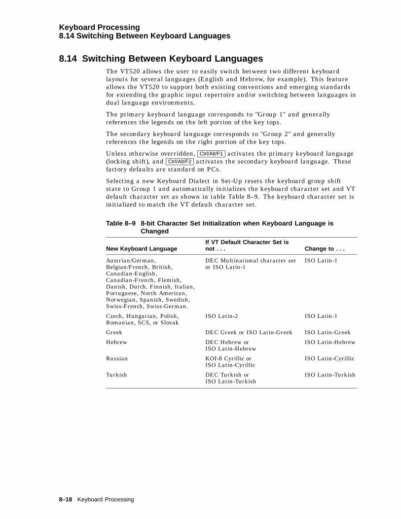
Keyboard Processing8.14 Switching Between Keyboard Languages
8.14 Switching Between Keyboard LanguagesThe VT520 allows the user to easily switch between two different keyboardlayouts for several languages (English and Hebrew, for example). This featureallows the VT520 to support both existing conventions and emerging standardsfor extending the graphic input repertoire and/or switching between languages indual language environments.
The primary keyboard language corresponds to "Group 1" and generallyreferences the legends on the left portion of the key tops.
The secondary keyboard language corresponds to "Group 2" and generallyreferences the legends on the right portion of the key tops.
Unless otherwise overridden, Ctrl/Alt/F1 activates the primary keyboard language(locking shift), and Ctrl/Alt/F2 activates the secondary keyboard language. Thesefactory defaults are standard on PCs.
Selecting a new Keyboard Dialect in Set-Up resets the keyboard group shiftstate to Group 1 and automatically initializes the keyboard character set and VTdefault character set as shown in table Table 8–9. The keyboard character set isinitialized to match the VT default character set.
Table 8–9 8-bit Character Set Initialization when Keyboard Language isChanged
New Keyboard LanguageIf VT Default Character Set isnot . . . Change to . . .
Austrian/German,Belgian/French, British,Canadian-English,Canadian-French, Flemish,Danish, Dutch, Finnish, Italian,Portuguese, North American,Norwegian, Spanish, Swedish,Swiss-French, Swiss-German.
DEC Multinational character setor ISO Latin-1
ISO Latin-1
Czech, Hungarian, Polish,Romanian, SCS, or Slovak
ISO Latin-2 ISO Latin-1
Greek DEC Greek or ISO Latin-Greek ISO Latin-Greek
Hebrew DEC Hebrew orISO Latin-Hebrew
ISO Latin-Hebrew
Russian KOI-8 Cyrillic orISO Latin-Cyrillic
ISO Latin-Cyrillic
Turkish DEC Turkish orISO Latin-Turkish
ISO Latin-Turkish
8–18 Keyboard Processing

Keyboard Processing8.14 Switching Between Keyboard Languages
If 7-bit NRCS characters is selected, then the following corresponding NRC setsare used.
Table 8–10 7-bit Character Set Initialization
Default Character Set
Keyboard VT Keyboard Enhanced PC Keyboard
Austrian/German German NRC Austrian/German NRC
Belgian/French French NRC French NRC
British (U.K.) U.K. NRC U.K. NRC
Canadian-English French Canadian NRC French Canadian NRC
Canadian-French French Canadian NRC French Canadian NRC
Czech N/A N/A
Danish Norwegian/Danish NRC Norwegian/Danish NRC
Dutch(Netherlands)
N/A1 N/A1
Finnish2 Finnish NRC Finnish NRC
Flemish French NRC N/A
Greek DEC Greek NRC DEC Greek NRC
Hebrew DEC 7-bit Hebrew DEC 7-bit Hebrew
Hungarian N/A N/A
Italian Italian NRC Italian NRC
North American(U.S.)3
N/A N/A
Norwegian Norwegian/Danish NRC Norwegian/Danish NRC
Polish N/A N/A
Portuguese Portuguese NRC Portuguese NRC
Romanian N/A N/A
Russian DEC Russian NRC DEC Russian NRC
SCS SCS NRC SCS NRC
Slovak N/A N/A
Spanish Spanish NRC Spanish NRC
Swedish Swedish NRC Swedish NRC
Swiss-French Swiss NRC Swiss NRC4
Swiss-German Swiss NRC Swiss NRC
Turkish-F DEC 7-bit Turkish N/A5
Turkish-Q DEC 7-bit Turkish DEC Turkish NRC
1Same as North American (U.S.) keyboard.2Same as Swedish keyboard.37-bit character mode is not available.4Swiss French/German is a single PC keyboard.5The VT keyboard is available in both the Turkish-F and Turkish-Q keyboard layouts. The EPCkeyboard is only available in the Turkish-Q layout.
Keyboard Processing 8–19

Keyboard Processing8.14 Switching Between Keyboard Languages
8.14.1 Keystroke ProcessingAny time the terminal is operating, a keyboard encoding is being used to translategraphic character keystrokes into character codes, called the keyboard characterset. The Keyboard Character set is a function of:
1. Keyboard language
2. Keyboard group (Hebrew only)
3. Default character set
4. The 7-bit or 8-bit characters setting
5. Any keyboard customization defined in Set-Up.
When the graphic character assigned to a keystroke (which usually correspondsto the legend appearing on the keycap) has a corresponding character in theKeyboard Character set, the terminal transmits the corresponding charactercode for that keystroke. The code transmitted for any given keystroke can varydepending on the Keyboard Character set. If the graphic character assigned toa keystroke does not have a corresponding character in the Keyboard Characterset, then that keystroke does not transmit any code.
8.14.2 Non-Spacing Accent MarksAccented characters that do not appear directly on a keyboard can often beentered by typing a non-spacing diacritical mark followed by a base character.While most diacritical marks have stand-alone forms (not in combination withanother character), the non-spacing interpretation of these marks are similar tocharacters but are actually a special internal keystroke representation.
Table 8–11 Non-Spacing Accent Marks
Symbol Non-Spacing Accent Name
´ Acute accent^ Breve_ Hacek (caron)
¸ Cedilla
^ Circumflex accent
¨ Diaeresis (umlaut)� Dot above00 Double acute accent
` Grave accent! Greek Tonos
¯ Macron
� Ogonek
° Ring above
~ Tilde
Keystrokes assigned non-spacing accent marks do not send any charactercode immediately, but are used instead to modify the code transmitted by thesubsequent keystroke. If a keystroke that has been assigned a non-spacing accentmark is followed immediately by a graphic character, then this forms a valid
8–20 Keyboard Processing

Keyboard Processing8.14 Switching Between Keyboard Languages
character in the keyboard character set, and the corresponding character code istransmitted.
When a non-spacing diacritical key is pressed, "Compose" appears on thekeyboard indicator line until the next subsequent keystroke.
If the keystroke immediately following the non-spacing diacritical keystrokedoes not form a valid character in the keyboard character set, then the non-spacing diacritical mark is converted to the corresponding character, if any, andtransmitted from the current keyboard character set. The second keystroke isthen processed normally. This "error recovery" is different from previous VTauto-compose processing; however, this process follows the emerging standardused on personal computers.
8.14.3 GermanFor German keyboards, the Group Shift (left Compose) key functions as thekeyboard repertoire extension mechanism. Group 1 and Group 2 are definedwithin the German keyboard dialect and are used whenever the keyboardlanguage is set to German. Group Shift operates as a single shift prefix if pressedand released or as a modifier key if pressed and held.
8.14.4 HebrewWhen Hebrew is selected as the Keyboard Dialect, the Ctrl/Hebrew key togglesbetween the primary and secondary keyboard language.
When switching into 7-bit Hebrew, lowercase English letters are swapped withtheir corresponding Hebrew characters throughout the display. The Shift/Hebrew
key also performs this swapping function at any time.
8.15 Keystation NumbersFigure 8–4 shows the keystation numbers for a VT keyboard.
Figure 8–4 VT Layout - Keystation Numbers
112 113 114 115 116 117 118 119 120 121
1 2 3 4 5 6 7 8 9 10 11 12 13 15
16 17 18 19 20 21 22 23 24 25 26 27 28
4358 30 31 32 33 34 35 36 37 38 39 40 41 42
44 45 46 47 48 49 50 51 52 53 54 55 57
59 60 61 62 63
122 123 124 125 126 127 130 131 132 133
99
108
75
76
79
80
81
83
84
85
86
89
90
91
92
93
95
96
97
98
100
101
102
103
104
105
106
107
Keyboard Processing 8–21

Keyboard Processing8.15 Keystation Numbers
Figure 8–5shows a typical legend for a North American VT keyboard.
Figure 8–5 VT Layout - Typical North American Key Legends
F1 F2 F3 F4 F5 F6 F7 F8 F9 F10
~`
!1
@2
#3
$4
%5
^6
&7
*8
(9
)0
_-
+=
Tab Q W E R T Y U I O P {[
}]
Ctrl Lock A S D F G H J K L :;
"'
|\
><
Z X C V B N M <,
>.
?/
ComposeCharacter
A ltFunction
Space A ltFunction
ComposeCharacter
F11 F12 F13 F14 Help Do F17 F18 F19 F20
0
Enter
Find Insert
Prev
Rem
Next
PF1
7
4
1
PF2
8
5
2
PF3
9
6
3
.
PF4
-
,
X
Return
Shift Shift
Select
Figure 8–6 Enhanced PC Layout - Map Numbers
112 113 114 115 116 117 118 119 120 121
1 2 3 4 5 6 7 8 9 10 11 12 13
16 17 18 19 20 21 22 23 24 25 26 27 28
4331 32 33 34 35 36 37 38 39 40 41
45 46 47 48 49 50 51 52 53 54 55
122 123
99
108
75
76
79
80
81
83
84
85
86
89
90
91
92
93
95
96
97
98
100
101
102
103
104
105
106
107
124 125 126
94 109
42
29
14 15
56
110
30
44
58 60 646261
57
65 66 67
Figure 8–7 Enhanced PC Layout - Typical North American Key Legends
F1 F2 F3 F4 F5 F6 F7 F8 F9 F10
~`
!1
@2
#3
$4
%5
^6
&7
*8
(9
)0
_-
+=
Tab Q W E R T Y U I O P{[
}]
EnterA S D F G H J K L:;
"'
Z X C V B N M<,
>.
?/
F11 F12
Enter
Ins
Del
Left
Home
End
Up
Down
PgUp
PgDn
Rght
NumLock
7Home
4Left
1End
/
8Up
5
2Down
*
9PgUp
6Rght
3PgDn
.Del
-
+
PrntScrn
ScrlLock Paus
|\
Esc
CapsLock
L Sht
Ctrl Alt CtrlAltSpace
NumLock
CapsLock
ScrollLock
Backspace
R Shift
0Ins
SyRq Break
8–22 Keyboard Processing

Keyboard Processing8.16 Scan Codes Sent in PCTerm Mode for EPC Keyboards
8.16 Scan Codes Sent in PCTerm Mode for EPC KeyboardsThe following keys send the corresponding scan codes, regardless of any modifiersthat may be in effect.
Key#
Legend(U.S.)
Scan CodeMake/Break 1
1 ‘ 29/A9
2 1 02/82
3 2 03/83
4 3 04/84
5 4 05/85
6 5 06/86
7 6 07/87
8 7 08/88
9 8 09/89
10 9 0A/8A
11 0 0B/8B
12 - 0C/8C
13 = 0D/8D
14 7D/FD2
15 Backspace 0E/8E
16 Tab 0F/8F
17 Q 10/90
18 W 11/91
19 E 12/92
20 R 13/93
21 T 14/94
22 Y 15/95
23 U 16/96
24 I 17/97
25 O 18/98
26 P 19/99
27 [ 1A/9A
28 ] 1B/9B
29 \ 2B/AB†
30 Caps Lock 3A/BA
31 A 1E/9E
32 S 1F/9F
33 D 20/A0
34 F 21/A1
1Make means when the key is pressed; Break means when the key is released.2Not used on 101/102 keyboard layout.†101 keyboard layout only
Keyboard Processing 8–23
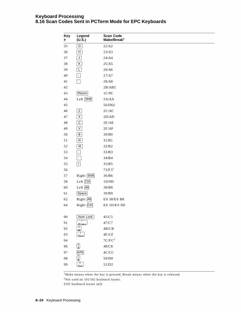
Keyboard Processing8.16 Scan Codes Sent in PCTerm Mode for EPC Keyboards
Key#
Legend(U.S.)
Scan CodeMake/Break 1
35 G 22/A2
36 H 23/A3
37 J 24/A4
38 K 25/A5
39 L 26/A6
40 ; 27/A7
41 ’ 28/A8
42 2B/AB‡
43 Return 1C/9C
44 Left Shift 2A/AA
45 56/D6‡
46 Z 2C/AC
47 X 2D/AD
48 C 2E/AE
49 V 2F/AF
50 B 30/B0
51 N 31/B1
52 M 32/B2
53 , 33/B3
54 . 34/B4
55 / 35/B5
56 73/F32
57 Right Shift 36/B6
58 Left Ctrl 1D/9D
60 Left Alt 38/B8
61 Space 39/B9
62 Right Alt E0 38/E0 B8
64 Right Ctrl E0 1D/E0 9D
90 Num Lock 45/C5
91 7Home
47/C7
92 4( 4B/CB
93 1End
4F/CF
94 7C/FC2
96 8* 48/C8
97 KP5 4C/CC
98 2+ 50/D0
99 0Ins
52/D2
1Make means when the key is pressed; Break means when the key is released.2Not used on 101/102 keyboard layout.‡102 keyboard layout only
8–24 Keyboard Processing
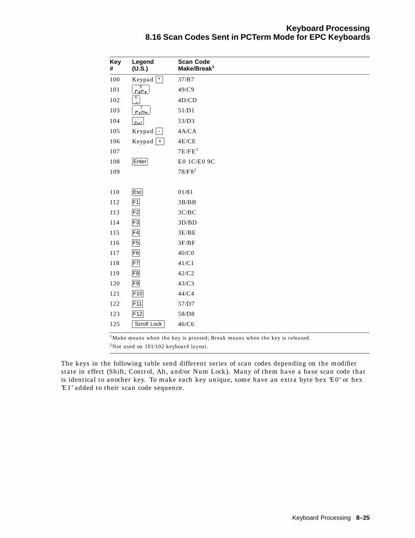
Keyboard Processing8.16 Scan Codes Sent in PCTerm Mode for EPC Keyboards
Key#
Legend(U.S.)
Scan CodeMake/Break 1
100 Keypad * 37/B7
101 9PgUp 49/C9
102 6) 4D/CD
103 3PgDn 51/D1
104 :
Del53/D3
105 Keypad - 4A/CA
106 Keypad + 4E/CE
107 7E/FE2
108 Enter E0 1C/E0 9C
109 78/F82
110 Esc 01/81
112 F1 3B/BB
113 F2 3C/BC
114 F3 3D/BD
115 F4 3E/BE
116 F5 3F/BF
117 F6 40/C0
118 F7 41/C1
119 F8 42/C2
120 F9 43/C3
121 F10 44/C4
122 F11 57/D7
123 F12 58/D8
125 Scroll Lock 46/C6
1Make means when the key is pressed; Break means when the key is released.2Not used on 101/102 keyboard layout.
The keys in the following table send different series of scan codes depending on the modifierstate in effect (Shift, Control, Alt, and/or Num Lock). Many of them have a base scan code thatis identical to another key. To make each key unique, some have an extra byte hex ’E0’ or hex’E1’ added to their scan code sequence.
Keyboard Processing 8–25
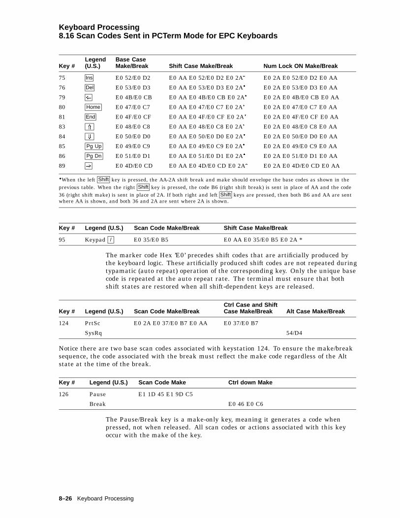
Keyboard Processing8.16 Scan Codes Sent in PCTerm Mode for EPC Keyboards
Key #Legend(U.S.)
Base CaseMake/Break Shift Case Make/Break Num Lock ON Make/Break
75 Ins E0 52/E0 D2 E0 AA E0 52/E0 D2 E0 2A� E0 2A E0 52/E0 D2 E0 AA
76 Del E0 53/E0 D3 E0 AA E0 53/E0 D3 E0 2A� E0 2A E0 53/E0 D3 E0 AA
79 ( E0 4B/E0 CB E0 AA E0 4B/E0 CB E0 2A� E0 2A E0 4B/E0 CB E0 AA
80 Home E0 47/E0 C7 E0 AA E0 47/E0 C7 E0 2A� E0 2A E0 47/E0 C7 E0 AA
81 End E0 4F/E0 CF E0 AA E0 4F/E0 CF E0 2A� E0 2A E0 4F/E0 CF E0 AA
83 * E0 48/E0 C8 E0 AA E0 48/E0 C8 E0 2A� E0 2A E0 48/E0 C8 E0 AA
84 + E0 50/E0 D0 E0 AA E0 50/E0 D0 E0 2A� E0 2A E0 50/E0 D0 E0 AA
85 Pg Up E0 49/E0 C9 E0 AA E0 49/E0 C9 E0 2A� E0 2A E0 49/E0 C9 E0 AA
86 Pg Dn E0 51/E0 D1 E0 AA E0 51/E0 D1 E0 2A� E0 2A E0 51/E0 D1 E0 AA
89 ) E0 4D/E0 CD E0 AA E0 4D/E0 CD E0 2A� E0 2A E0 4D/E0 CD E0 AA
�When the left Shift key is pressed, the AA-2A shift break and make should envelope the base codes as shown in theprevious table. When the right Shift key is pressed, the code B6 (right shift break) is sent in place of AA and the code36 (right shift make) is sent in place of 2A. If both right and left Shift keys are pressed, then both B6 and AA are sentwhere AA is shown, and both 36 and 2A are sent where 2A is shown.
Key # Legend (U.S.) Scan Code Make/Break Shift Case Make/Break
95 Keypad / E0 35/E0 B5 E0 AA E0 35/E0 B5 E0 2A *
The marker code Hex ’E0’ precedes shift codes that are artificially produced bythe keyboard logic. These artificially produced shift codes are not repeated duringtypamatic (auto repeat) operation of the corresponding key. Only the unique basecode is repeated at the auto repeat rate. The terminal must ensure that bothshift states are restored when all shift-dependent keys are released.
Key # Legend (U.S.) Scan Code Make/BreakCtrl Case and ShiftCase Make/Break Alt Case Make/Break
124 PrtSc E0 2A E0 37/E0 B7 E0 AA E0 37/E0 B7
SysRq 54/D4
Notice there are two base scan codes associated with keystation 124. To ensure the make/breaksequence, the code associated with the break must reflect the make code regardless of the Altstate at the time of the break.
Key # Legend (U.S.) Scan Code Make Ctrl down Make
126 Pause E1 1D 45 E1 9D C5
Break E0 46 E0 C6
The Pause/Break key is a make-only key, meaning it generates a code whenpressed, not when released. All scan codes or actions associated with this keyoccur with the make of the key.
8–26 Keyboard Processing

Keyboard Processing8.17 Scan Codes Sent in PCTerm Mode for VT Keyboards
8.17 Scan Codes Sent in PCTerm Mode for VT KeyboardsAll keystrokes send scan codes except:
Key Which sends . . .
Caps Lock F1 Hold
Caps Lock F2 Print
Caps Lock F3 Enter Set-Up
Caps Lock F5 Send Break
All keys including Shift, Alt, and Ctrl send make codes immediately upon beingpressed, except the Caps Lock key. The make code for the Caps Lock key is sentafter the Caps Lock key is released. The following keys send the correspondingscan codes, regardless of any modifiers that may be in effect.
Key#
Legend(U.S.)
Scan CodeMake/Break
42 \ 2B/AB
107 - 1 7E/FE
124 F13 E0 3D/E0 BD
125 F14 E0 3E/E0 BE
126 Help E0 3F/E0 BF
127 Do 01/81 (Like Esc key on PC keyboard)
130 F17 E0 41/E0 C1
131 Print Screen E0 2A E0 37/E0 B7 E0 AACtrl or Shift E0 37/E0 B7
Sys Rq Alt 54/D4
132 Scroll Lock 46/C6
133 Pause 2 E1 1D 45 E1 9D C5
Break 2 Ctrl E0 46 E0 C6
1On Numeric keypad.2This is a make-only key; code is sent only when key is pressed.
Keyboard Processing 8–27

Keyboard Processing8.18 Control Codes and Keystrokes
8.18 Control Codes and KeystrokesThe following codes are transmitted when the Ctrl key is depressed simultaneouslywith another key.
Table 8–12 Control Codes and Keystrokes
Legend HEX Code Transmitted Name
Ctrl Space 00 NUL
Ctrl 2 00 NUL
Ctrl A 01 SOH
Ctrl B 02 STX
Ctrl C 03 ETX
Ctrl D 04 EOT
Ctrl E 05 ENQ
Ctrl F 06 ACK
Ctrl G 07 BEL
Ctrl H 08 BS
Ctrl I 09 HT
Ctrl J 0A LF
Ctrl K 0B VT
Ctrl L 0C FF
Ctrl M 0D CR
Ctrl N 0E SO
Ctrl O 0F SI
Ctrl P 10 DLE
Ctrl Q 11 DC1†
Ctrl R 12 DC2
Ctrl S 13 DC3†
Ctrl T 14 DC4
Ctrl U 15 NAK
Ctrl V 16 SYN
Ctrl W 17 ETB
Ctrl X 18 CAN
Ctrl Y 19 EM
Ctrl Z 1A SUB
Ctrl 3 1B ESC
Ctrl [ 1B ESC
Ctrl 4 1C FS
Ctrl \ 1C FS
Ctrl 5 1D GS
Ctrl ] 1D GS
†Code is transmitted if XON/XOFF handling is disabled.
(continued on next page)
8–28 Keyboard Processing

Keyboard Processing8.18 Control Codes and Keystrokes
Table 8–12 (Cont.) Control Codes and Keystrokes
Legend HEX Code Transmitted Name
Ctrl 6 1E RS
Ctrl ~ 1E RS
Ctrl 7 1F US
Ctrl ? 1F US
Ctrl 8 7F DEL
Ctrl Tab 09 HT
Ctrl Enter Same as Enter alone.
Ctrl Return Same as Return alone.
Ctrl Delete 18 CAN
Keyboard Processing 8–29


9Communications
This chapter describes the serial asynchronous communications through the hostports.
9.1 Introduction to CommunicationsThis chapter describes the physical layer and data link layer. The physical layeris comprised of the mechanical, electrical, and functional arrangements necessaryfor a physical connection, including cables and telephone lines. The physical layerapplies to both ANSI and ASCII terminal emulations.
The data link layer is the electronic protocol used to convey a unit of informationfrom the VT520 to a host computer. This layer includes flow control, characterconversions, and some forms of error control.
The asynchronous character format consists of a start bit (space), the data bits(1=mark, 0=space), the parity bit (if present), and one or two stop bits (mark).The data bits represent a character with the least significant bit leading. Theparity bit may be enabled as either none, odd, even, space, or mark. Receivedparity may be checked or ignored. When transmitting odd or even parity, thereceived parity must be set to the same parity as the transmitted data. Theseparameters can be selected through Set-Up or by using the escape sequence,DECSPP.
For further information on the asynchronous character format, refer to ANSIX3.15-1976, American National Standard for bit sequencing of the AmericanNational Standard Code for Information Interchange in Serial-By-Bit DataTransmission.
The VT520 supports the following:
Full-duplex modeHalf-duplex mode
Full-duplex mode allows simultaneous two-way communication, while half-duplexmode limits communication to one way at any given time. The VT520 alwayssupports full duplex (two wires) at the physical layer. Half-duplex mode is asimple data link layer protocol intended to support half-duplex modems. It iscommon to view the terminal and attached modem as a single system. Refer toSection 9.2.4 for details on half-duplex mode. This feature can be selected fromSet-Up or by the control function, DECHDPXM.
The VT520 does not support synchronous communications.
Communications 9–1

Communications9.2 Physical Link Layer
9.2 Physical Link LayerCommunications lines may be connected to the comm ports without interactionbetween the two lines. You can use the Set-Up menu Communication -Port select to select the communications port. The port selection can also beprogrammed through the escape sequence, DECSCP.
9.2.1 25-Pin ConnectorsFigure 9–1 shows the typical 25-pin EIA 232 ports.1 You can only use oneconnector at a time.
Figure 9–1 25-Pin Port Pin Numbers
2 TXD3 RXD4 RTS5 CTS6 DSR7 SIG GND8 CD
12 SI
23 SPD SEL9−11, 13−19, 21, 22, 24, 25 NC
20 DTR
MA−0019−93.GRA
105/CA/S2
103/BA/D1
106/CB/M2
104/BB/D2
107/CC/M1102/AB/E2109/CF/M5112/CI108.2/CD/S1.2111/CH/S4
CCITT/EIA/DIN11 GND / NC
F M
114
1325
13 25 114
Comm1, a DB-25P serial port, has full modem control, accepting a variety ofmodems that meet national and international standards.
Comm2 has data lead only and RS-423 drivers.
Table 9–1 shows the interface signals and functions. Interface signals are labeledwith both EIA and CCITT designations.
Table 9–1 EIA Interface Signals and Functions
Pin Signal Name Source Function CCITT/EIA/DIN
1 GND Ground
2 TXD L Terminal Transmitted Data 103/BA/D1
3 RXD L Modem Received Data 104/BB/D2
4 RTS Terminal Request to Send 105/CA/S2
5 CTS Modem Clear to Send 106/CB/M2
6 DSR Modem Data Set Ready 107/CC/M1
7 SGND Signal Ground 102/AB/E2
8 RLSD Modem Rec Line Signal Detector 109/CF/M5
9-11, 13-19, 21, 22, 24, 25 No connection
(continued on next page)
1 Normally grounded on the VT520. NC = no connection.
9–2 Communications

Communications9.2 Physical Link Layer
Table 9–1 (Cont.) EIA Interface Signals and Functions
Pin Signal Name Source Function CCITT/EIA/DIN
12 SPDI Modem Speed Mode Indication 112/CI/M4
20 DTR Terminal Data Term. Ready 108.2/CD/S1.2
23 SPD SEL L Terminal Speed Select 111/CH/S4
9.2.2 DEC Corporate Modular Jacks (MMJ)The modular jacks provide DEC-423 compatible levels with the intent of allowinggreater length between terminal and host. Limited modem support is alsoprovided. The DTR output and DSR input are supported on this connector. DEC-423 signals provide separate ground lines for TXD and RXD signals. Transmitground for transmit data and DTR are isolated from receive ground used forreceive data and DSR. Figure 9–2 shows the MMJ port signals.
Figure 9–2 MMJ Modular Jack Pin Numbers
1 6
MA−0020−93.GRA
1 DTR
6 DSR
2 TXD +
5 RXD + 4 RXD −3 TXD −
Table 9–2 describes the function of each MMJ interface signal.
Table 9–2 MMJ Interface Signals
Pin Signal Name Source Function
1 DTR Terminal Data Terminal Ready�
2 TXD + Terminal Transmitted Data
3 RXD - Terminal Transmit Signal Ground
4 RXD - Modem Receive Signal Ground
5 RXD + Modem Received Data
6 DSR Modem Data Set Ready†
�Pin 1 is a terminal output signal and uses pin 3 as a reference.†Pin 6 is a terminal input signal and uses pin 4 as a reference.
9.2.3 Connector Pins DescriptionThis section describes the function of full-duplex mode connector pins. Half-duplex mode connector pins have different functions than the full-duplex modeconnector pins as mentioned in Section 9.2.4.
Communications 9–3
Communications9.2 Physical Link Layer
9.2.3.1 Transmitted Data–TXD LThe TXD L signal is supported on the 25-pin D-sub and the Corporate ModularConnector.
Data on this circuit represents the serially encoded characters that aretransmitted from the VT520. This circuit is held at the mark state (-) duringstop bits between characters and also at times when no data is being transmitted.
On the 25-pin connector when modem control is enabled, no data is transmittedunless Clear to Send is asserted from the modem. Assertion of DSR or RLSDfrom the modem is not required. This is specific to the 25-pin EIA connector andis intended to allow the VT520 to communicate with intelligent modems (like theDF224) before a connection has been established.
9.2.3.2 Received Data–RXD LThe RXD L signal is supported on the 25-pin D-sub as well as on the CorporateModular Connector.
Data on this circuit represents the serially encoded characters to be received bythe VT520.
When modem control is not enabled, received data is processed regardless of thestate of the control lines.
On a 25-pin EIA connector, when modem control is enabled and a connectionhas been established (DSR from the modem is asserted), the received charactersare ignored if RLSD is unasserted, except when Disconnect Delay in Set-up isselected as No disconnect. This is an implementation in firmware of markcarrier clamping.
If a connection has not been established (DSR from the modem is not asserted),then received characters are processed even if RLSD is unasserted. This is animplementation that permits V.25 bis compatible autodial modems to be usedwithout the user having to set "data leads only" to access the autodial functions.
9.2.3.3 Request to Send–RTSThe RTS signal is supported on the 25-pin D-sub but not on the CorporateModular Connector.
For modems with this function, asserting RTS may put the modem in thetransmit mode. When the modem is in the transmit mode, it then asserts CTS.
Note
For full-duplex modems without RTS inputs, CTS is asserted by themodem whenever it is capable of transmission.
9.2.3.4 Clear to Send–CTSThe CTS signal is supported on the 25-pin D-sub but not on the CorporateModular Connector.
Assertion of CTS indicates that the modem is ready to receive data (that is, theterminal is clear to send data to the modem).
The data can be either a command to the modem if "off line" (DSR de-asserted) ortransmitted data to the host if "on line" (DSR asserted).
9–4 Communications
Communications9.2 Physical Link Layer
9.2.3.5 Data Terminal Ready–DTRThe DTR signal is supported on the 25-pin D-sub as well as the CorporateModular Connector.
The VT520 asserts DTR whenever it is ready to transmit and/or receive on theport to which it is associated with.
The VT520 de-asserts DTR when:
• Recalling saved settings
• Recalling factory defaults
• Pressing Shift/Break
• Powering up self-test
• Resetting to Initial State (RIS)–hard reset
• DTR is being used for hardware flow control and the receive buffer hasreached the flow control threshold
The VT520 does not de-assert DTR when:
• Resetting session
• Clearing comm
9.2.3.6 Data Set Ready–DSRThe DSR signal is supported on the 25-pin D-sub as well as the CorporateModular Connector.
When the DTR/DSR is not the selected flow control scheme, the assertion of DSRindicates the following:
• That the modem is in the data mode
• That the modem is connected to the communications channel
• The answer tone is finished
• The user is being charged by the PTT
• That the modem is ready to exchange the appropriate control signals toinitiate data transmission/reception
When DTR/DSR is the selected hardware flow control scheme only, refer toSection 9.3.2.2.3.
9.2.3.6.1 Modem Initiated Disconnect When DSR is unasserted during theprogress of a call but before DTR is unasserted, the terminal interprets thiscondition as a lost or aborted call and disconnects. Any subsequent assertion ofDSR is considered a new call. If connected to a modem and the modem’s poweris turned off or if DSR becomes an open circuit, then the VT520 interprets theseconditions as a de-assertion. The state of the DSR input is shown on the indicatorstatus line display.
9.2.3.6.2 Terminal Initiated Disconnect The terminal disconnects itself fromthe modem by dropping DTR.
Communications 9–5

Communications9.2 Physical Link Layer
220 ms
A B
DTR
DSR
Terminal Initiated Disconnect
If DSR is de-asserted 220 ms after DTR goes de-asserted, then do nothing, sincethe modem has already done a disconnect. If DSR is still asserted 220 ms afterDTR goes deasserted, then DTR must remain deasserted for greater than 2seconds to assure that the modem does a disconnect.
9.2.3.6.3 Modem off line When DSR is unasserted and modem control isenabled on the 25-pin EIA connector, the system is in a transitory "off line" state.In this state, the user may interact with a dial-up modem to enter numbers,change modem set-up, and so on.
When DSR is asserted and modem control is being used, the modem, terminal,and host system are ready for communication to a remote host.
9.2.3.7 Receive Line Signal Detector–RLSDThis signal is supported on the 25-pin D-sub but not on the Corporate ModularConnector.
RLSD is also called Carrier Detect. The modem asserts RLSD when the receivedsignal is of sufficient amplitude or in the case of "training modems," when bothmodems have adjusted and equalized to the prevailing line conditions, to ensuredemodulation of Received Data. The unasserted condition of RLSD indicates thatthere is neither a received signal nor that it is unsuitable for demodulation.
9.2.3.8 Speed Indicator–SPDIThe SPDI signal is supported on the 25-pin D-sub but not on the CorporateModular Connector. This signal comes from the modem. When Modem Controlis enabled in Set-Up, the transmit and receive speed is set as follows:
State Transmit and Receive Speed
Unasserted Modem Low Speed
Asserted Modem High Speed (default)
The user should set these Set-Up fields so that the fast speed (2400 baud, forexample) is exactly twice the slow (1200 baud, in the following example) if V.25bis compatibility is desired. Otherwise, the user may set the two speeds asapplicable (1200/300 baud, in the following example).
Assert De-assert
Bell 212 1200 300
Bell 103 300 n/a
V.22 1200 600
V.22 bis 2400 1200
V.26 ter 2400 1200
V.32 4800 2400
V.32 9600 4800
9–6 Communications
Communications9.2 Physical Link Layer
9.2.3.9 Speed Select–SPDSThe SPDS signal is supported on the 25-pin D-sub but not on the CorporateModular Connector.
If the speed is greater or equal to 1200 baud, then Speed Select will be high. Ifthe speed is below 1200 baud, then Speed Select will be slow. This signal comesfrom the terminal.
9.2.4 Half-Duplex ModeHalf-duplex mode works in EIA 232-E line only. It uses the pin signals to controlthe data traffic to one direction at any given time.
In this mode, Data Terminal Ready (DTR) is always asserted. The terminalchecks the assertion of Data Set Ready (DSR) constantly. The terminaldisconnects once DSR is dropped. Ready to Send (RTS) is asserted only ifthe terminal intends to transmit.
Before transmitting, the terminal checks for the presence of Carrier Detect (CD).If CD is still detected for five seconds, then the terminal disconnects. Otherwise,the terminal asserts the Request to Send (RTS) signal and starts detectingthe Clear to Send (CTS) signal. Transmission starts if CTS is detected withinfive seconds. If CTS is not monitored within five seconds, then the terminaldisconnects. After transmission, RTS is de-asserted from the terminal. If CTS isstill detected within the next five seconds, then the terminal disconnects.
9.2.5 Supported Modem ConfigurationsThis section describes the supported modem configurations.
9.2.5.1 CCITT Public Switched Telephone Network (2-wire only)
V.21 Modem (V.24/V.28)Async, FDX, up to 200/300 bit/sV.22 Modem (V.24/V.28)Async, FDX, up to 1200 bit/sV.22 bis Modem (V.24/V.28)Async, FDX, up to 2400 bit/sV.23 Modem (V.24/V.28)Async, Asymmetric FDXReceive = 600 or 1200 bit/s,Transmit = Reverse channel at 75 bit/sV.25 bis Auto Dial Protocol Modem and Hayes
9.2.5.2 CCITT Dedicated Line (2-Wire / 4-Wire) Data Network
V.21 Modem (V.24/V.28, 2-W)Async, FDX, 200/300 BV.23 Modem (V.24/V.28)FDX, Async, 1200 B, 4-WV.25 bis compatible ModemAsync, FDX, any standard speed from 300 baud up.X.20 bis Full-Duplex asynchronous 300 baud data service unit
Communications 9–7

Communications9.2 Physical Link Layer
9.2.5.3 European Public Circuit Switched Data Network
D1200S (Germany)VC-DCE (Nordic Network)VPC-DCE (Nordic Network)X.20bis (V.21) Data Service Unit (V.28)Async, FDX, up to 300 B
9.2.5.4 European Public Packet Switched Data Network (PSDN)
Germany: DATEX-PBasic Datex P10-Service (X.25): Not supportedAdditional Datex-P20 Service:
Fixed Connections to PAD facility with X.28 procedure:
Service DCE
DATEX-P20H300
DFG300(X.20 bis), D300S (V.21)
DATEX-P20H1200
D1200S12(V.22), D1200S (V.23,4-W)
DATEX-P20H1200/75
D1200S (V.23 with sec. channel, 75 baud Transmit / 1200 BaudReceive)
DATEX-P20H2400
Access to DATEX-P PAD facility from other public switched networks withX.28 procedure:
Service Access DCE
DATEX-P20L300
DATEX-L DFG300 (X.20bis)
DATEX-P20F300
PSTN D300S (V.21)
DATEX-P20F1200
PSTN D1200S12 (V.22)
DATEX-P20F1200/75
PSTN D1200S (V.23 with sec channel, 75 baudTransmit, 1200 baud Receive)
DATEX-P20F2400
9–8 Communications

Communications9.3 Data Link Layer
9.3 Data Link LayerThis section describes the data link layer.
9.3.1 7- /8-Bit VT100/VT520 OperationThe VT520 supports three broad classes of application requirements:
• Strict compatibility for existing VT100 applications:
– No 8-bit control codes
– No 8-bit data Function keys are not limited to the VT100 set as inprevious terminals.
• A migration path that allows most applications to run without modification:
– No 8-bit control codes
– 8-bit graphic data allowable
– VT400 function keys are allowable (but not immediately useful) and canbe integrated into the application over time.
• Full VT520 mode (VT level 5) functionality:
– 8-bit data allowable
– 8-bit controls allowable
– All VT500 function and modifier keys
The VT520 application requirements are possible through the following VTterminal modes:
• VT52 Mode (7-bit characters, 7-bit controls)
• VT100 Mode (7-bit characters, 7-bit controls)
• VT500 Mode, 8-bit characters, 7-bit controls
• VT500 Mode, 8-bit characters, 8-bit controls
• VT500 Mode, 7-bit characters (Keyboard restricted to keys that generate 7-bitcodes, 7-bit graphics, 7-bit controls, for NRC sets, worldwide version only).
These modes are the only supported modes. 8-bit characters are temporarilydisabled when in VT100 mode.
The following are certain limitations within these modes:
• The terminal accepts both C0 and C1 controls when 8-bit characters areselected (7-bit NRCS Characters is not selected).
• The terminal accepts both GL and GR characters when 8-bit Characters areselected.
• In VT52 mode, VT100 mode, or VT500 mode, when 7-bit characters isselected, the terminal sets the high bit of all received characters to zero. Thisaction results in compatible character handling. The received characters,therefore, have only seven significant bits. This is applicable to both graphicscharacters and control characters.
Communications 9–9
Communications9.3 Data Link Layer
• If the user needs to restrict the controls to 7 bits, but still needs 8-bit graphiccharacters and new function keys, then the user can select Transmit 7-bitcontrols with an 8-bit host line. To get full efficiency out of new applications,select 8-bit controls and an 8-bit host line. The 7-bit NRCS Charactersselection is compatible with 7-bit NRC-based applications.
• C1 controls are never available directly from the default keyboard, althoughthey may be available indirectly through the function keys or numericcompose.
• When the terminal is in printer controller mode and the 7-bit character mode,upon receiving 8-bit graphic characters, the terminal immediately retransmitsthem through the printer port to the printer. The highest bit is not strippedoff.
• In printer controller mode when the terminal is receiving 8-bit characters andimmediately retransmitting them on a 7-bit line, the high bit is stripped off.
• When the screen contains 8-bit (GR) characters and is being printed on a7-bit printer, the characters are subject to constraints, which are described inChapter 10.
• Keyboard operation guidelines are described in Chapter 8.
9.3.2 Flow ControlFlow control is a means to alternately suspend and resume the flow of charactersover serial asynchronous point-to-point communication lines.
Depending on the type of flow control selected, the stop/resume transmissionsignal is different. Users can select a software flow control scheme, a hardwareflow control scheme, or a combination software and hardware flow control schemeto meet their communication environment.
9.3.2.1 Receive BufferThe VT520 operates at a transmission speed of up to 115.2K baud. To preventloss of data, the receive buffer is 1024 byte. The substitute (SUB) character issubstituted in the input buffer for any character with detected receive parityerrors or framing errors. If the input buffer overflows, a SUB character is placedin the buffer in place of the lost characters. The SUB character is displayed as areverse question mark.
9.3.2.2 Flow Control SelectionThe VT520 supports bidirectional flow control. The flow control scheme can beselected independently for the transmit and receive direction. The user has thefollowing choices for transmit data flow control:
• No Flow Control
• XON/XOFF
• DTR
• Both
The user has the following choices for receive flow control:
• No Flow Control
• XON/XOFF in VT mode or XPC in PC term mode
• DSR
9–10 Communications
Communications9.3 Data Link Layer
• Both
You can select flow control methods from Set-Up or through the escape sequences,DECSFC.
9.3.2.2.1 No Flow Control If No Flow Control is selected, then when thereceive buffer is full, it does not send any signal; therefore, the Hold keyis disabled. Ctrl/S and Ctrl/Q will be transmitted as typed. It is left to theapplication and user to prevent buffer overflow.
Software that does not support flow control may use all the features of the VT520by treating NUL as a fill character. If Ignore NUL is selected in Set-Up, thenNUL is discarded upon receipt. All other received characters are stored in theinput buffer for further processing. Ignore NUL or Accept NUL can be selectedfrom Set-Up or through the escape sequence, DECNULM.
The VT520 can be used without flow control or fill characters, when the:
• Software never sends ESC sequences to the terminal
• Baud rate is limited to 19200 baud or less
• Software does not use smooth scrolling
9.3.2.2.2 XOFF/XON or XPC Flow Control
In the XOFF/XON flow control, two characters establish flow control. In VT mode,these two characters are DC1(11H) (XON) and DC3(13H) (XOFF). In VT mode,the VT520 sends XOFF to suspend the host transmission of data and XON toresume that transmission. Receipt of XOFF inhibits the host from transmittingany code except XOFF and XON. Once the keyboard buffer becomes full, nomore keystrokes are accepted. The keyboard locks and "wait" is displayed in thekeyboard indicator line. Transmission resumes when the host receives an XON.
In PC Term mode, the terminal receives from the host 11H(DC1) and 13H(DC3)for flow control; but the terminal sends 65H and 67H to the host to resume/stopthe communication, known as XPC flow control.
VT520 sends XOFF to indicate halt of transmission when:
1. The number of characters in the input buffer reaches the first XOFF pointsince the last XON was sent.
2. The number of characters in the input buffer reaches the second XOFF pointsince the last XON was sent.
3. The input buffer is full.
4. Entering a hold state.
Entering a Hold state causes an XOFF to be sent by the VT520. A Hold state canbe generated by pressing the Hold key or entering Ctrl/S . When exiting from thehold state either by depressing the Hold key or entering Ctrl/Q , the terminal sendsXON to the host unless the input buffer is filled up to or beyond the first XOFFpoint (flow control threshold).
With the exception of exiting from the hold state, the VT520 sends an XON whenthe input buffer is emptied to the XON point and when XOFF was the last flowcontrol sent.
Refer to the Section 9.3.2.2.5 for more information on the thresholds.
Communications 9–11

Communications9.3 Data Link Layer
The VT520 re-initializes the XON/XOFF(XPC) state under the followingconditions:
1. The Clear Comm function is performed.
2. The completion of the NVR recall after the RECALL function is performed.
3. The completion of all tests in a self-test sequence is performed.
4. Successful completion of a connection - generally, DSR assertion.
5. The reception of RIS.
9.3.2.2.3 DSR/DTR Flow Control
When Hardware flow control is selected, DTR is asserted any time theterminal is not in self-test and the terminal’s input buffer is below the flowcontrol threshold; DTR is de-asserted when the input buffer is filled up to orbeyond the threshold.
If the terminal is a sending device, then it polls DSR before transmitting eachcharacter. If DSR is not being asserted by the receiving device, then transmissionof the character is suspended until DSR is asserted.
As in the XON/XOFF software flow control, VT520 deasserts DTR when:
1. The number of characters in the input buffer is greater than or equal to theflow control threshold (first XOFF point).
2. Entering the Hold state.
As in the XON/XOFF flow control, entering a Hold state causes a deassertion ofDTR. When exiting from the hold state either by depressing the Hold key or byentering Ctrl/Q ", the terminal asserts DTR unless the input buffer is filled up toor beyond the flow control threshold (first XOFF point).
With the exception of exiting from the hold state, the VT520 reasserts DTR whenthe input buffer is emptied to the "resume transmission" (XON) point.
DSR/DTR can be used for hardware flow control when they are not needed formodem control functions. When Modem Control is enabled, DST/DTR shouldnot be selectable.
9.3.2.2.4 Software and Hardware Combined Flow Control
For software and hardware flow control, both DTR/DSR and XON/XOFF(XPC)are used to control the data flow. When the receive input buffer reaches the flowcontrol threshold, XOFF is sent and DTR is deasserted. When transmitting,the terminal must be in the XON state with DSR asserted to transmit the nextcharacter, except in the case of (XON/XOFF).
9.3.2.2.5 Flow Control Threshold
Table 9–3 shows the flow control threshold points available for the VT520.
9–12 Communications
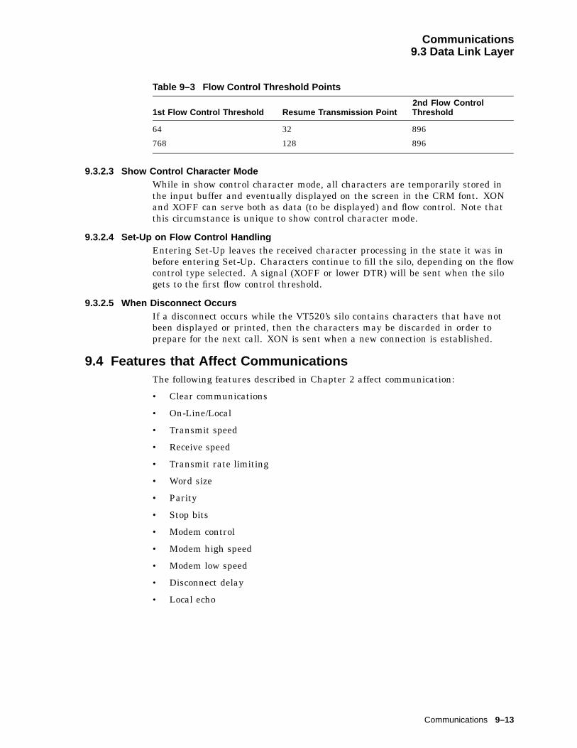
Communications9.3 Data Link Layer
Table 9–3 Flow Control Threshold Points
1st Flow Control Threshold Resume Transmission Point2nd Flow ControlThreshold
64 32 896
768 128 896
9.3.2.3 Show Control Character ModeWhile in show control character mode, all characters are temporarily stored inthe input buffer and eventually displayed on the screen in the CRM font. XONand XOFF can serve both as data (to be displayed) and flow control. Note thatthis circumstance is unique to show control character mode.
9.3.2.4 Set-Up on Flow Control HandlingEntering Set-Up leaves the received character processing in the state it was inbefore entering Set-Up. Characters continue to fill the silo, depending on the flowcontrol type selected. A signal (XOFF or lower DTR) will be sent when the silogets to the first flow control threshold.
9.3.2.5 When Disconnect OccursIf a disconnect occurs while the VT520’s silo contains characters that have notbeen displayed or printed, then the characters may be discarded in order toprepare for the next call. XON is sent when a new connection is established.
9.4 Features that Affect CommunicationsThe following features described in Chapter 2 affect communication:
• Clear communications
• On-Line/Local
• Transmit speed
• Receive speed
• Transmit rate limiting
• Word size
• Parity
• Stop bits
• Modem control
• Modem high speed
• Modem low speed
• Disconnect delay
• Local echo
Communications 9–13
Communications9.4 Features that Affect Communications
9.4.1 Clear CommunicationsIf the terminal appears to be "locked" in Set-Up, then select Clearcommunications to clear the current session. This action:
1. Aborts any print operation in progress if the printer is allocated to the activesession.
2. Aborts any escape sequence, control sequence, or device control string (DCS)processing.
3. Clears the keyboard buffer.
4. Clears the receive buffer.
5. Clears the transmit buffer.
6. Takes the terminal out of printer controller mode.
7. Sends XON to the host port if software flow control is in use. Asserts DTR ifhardware flow control is in use.
8. Resets XOFF received flags on the printer and host ports if software flowcontrol is in use.
The communications has been cleared when "Done" appears on the terminalstatus line.
Note
Clear communications does not cause a disconnect and does not clearthe screen.
9.4.2 ConnectionIf XON/XOFF flow control is enabled, then a single XON will be transmitted afterthe connection is made. When a connection is made, the VT520 performs thefollowing operations to ensure that it is ready to send and receive:
1. Unlock the keyboard, if it is locked.
2. Clear any transmit in progress on this port.
3. Clear all buffers associated with this port.
4. Clear the "XOFF sent" and "XOFF received" state of this port.
5. At the reception of the carrier tone, the modem asserts CD, and datatransmission/reception may begin.
9.4.3 Line DisconnectionA disconnect sequence occurs on the following conditions:
• Operator initiates a disconnect by pressing Shift/Break (note that the BREAKcan be disabled through Keyboard Set-Up).
• Doing a RECALL, or DEFAULT. (If a terminal supports more than onesession, this only disconnects the active session’s line.)
• Loss of DSR.
• Switching to the EIA 232-E port from the DEC423 port or to the DEC423 portfrom the EIA232-E port.
9–14 Communications

Communications9.4 Features that Affect Communications
• With the 25-pin connector and modem control enabled, after a connection hasbeen established, loss of RLSD for greater than 2 seconds (or 60 ms) on hostline 1.
• Receipt of a DECTST or RIS sequence (Except the keyboard test in DECTSTthat leaves the terminal on line).
• Turning off the terminal.
v
v
vv
Initiate Disconnect
RTS = OffDTR = Off
TxD = MarkStart 220 ms timer
> 220 ms
DSR = Off or> 1.8 s
Exit Subroutine
Start 1.8 s timer
MA−0029−93.GRA
Normally DTR and RTS are asserted by the VT520 whenever power is appliedexcept:
– During a disconnect sequence
– When hardware flow control DTR/DSR is being used and the receive bufferreaches 64 bytes threshold
9.4.4 BreakThe Break key operates as described in Chapter 8.
A break consists of a 275 ± 25 ms space condition on the transmit data lineif transmission is enabled. The break (space) condition is separated from anysubsequent mark-to-space transition by at least 100 ms.
9.4.4.1 Received BreakIf a break is detected on the received data circuit, then it is ignored. One or moreerror characters (reverse question mark) may be displayed because the framingerrors were generated.
Communications 9–15


10Printer Port
10.1 OverviewThe VT520 expands the traditional printer port extension to include support forIBM ProPrinter and compatible low-cost parallel interface printers. In Set-Up,you specify the type of printer attached and the terminal automatically selectsthe correct printing commands and character sets.
The VT520 printer port has the following features:
• Centronics parallel port (25-pin, female, D-type connector)
• IBM ProPrinter mode
• Ability to transparently pass all characters (including the NUL character)through to the printer in printer controller mode
You can connect both a serial and a parallel printer to the VT520 at the sametime, and both printer ports can be active at the same time if used by differentsessions.
10.2 Serial PortThe VT520 uses Comm3 and the serial printer port with speeds of 300 to 115.2Kbaud. Comm 3 is a 6-pin MMJ connector with EIA 423 levels.
The interface signals are the same as those previously described in Chapter 9.
10.2.1 Serial Port Flow ControlThe VT520 serial printer port is fully bi-directional when Printer To Hostcommunications is enabled in Set-Up or by a Media Copy (MC) control sequence.The printer port has two buffers: one is for output, which is 16 bytes long; andthe other is for input, which is 254 bytes long.
The firmware supports bi-directional flow control on the printer port. Transmitand receive flow control protocols can be set independently to one of four choicesthrough Set-Up or by the control sequence, DECSFC.
• None
• XON/XOFF
• DTR/DSR
• Both
XON/XOFF: For the 254-character receive input buffer, the XON point is 32. Thefirst XOFF point is 64 characters, and the second is 220 characters.
Printer Port 10–1

Printer Port10.2 Serial Port
DTR/DSR: If enabled, the terminal polls DSR before transmitting each character.The terminal asserts DTR until the buffer fills up to or beyond the first XOFFpoint. When the buffer empties to the XON point, the terminal again assertsDTR. When not used for hardware flow control, DTR is asserted whenever thefirmware is active and not in its self-test.
When the input buffer is full and receives another character byte, it overflows. Inthe event of an input buffer overflow, the last byte in the buffer is replaced withthe SUB character.
10.3 Parallel PortThe Centronics parallel interface is considered to be industry standard and isnot explained in this chapter. This port uses a 25-pin D-type connector with pinassignments shown in Figure 10–1 and listed in Table 10–1.
Figure 10–1 Parallel Printer Port
F
2 DAT <0>3 DAT <1>4 DAT <2>5 DAT <3>6 DAT <4>7 DAT <5>8 DAT <6>9 DAT <7>
11 BUSY10 ACKNLG L
12 PE13 SLCT14 AUTO FEED XT L15 ERROR L16 INIT L17 SLCT IN L18 − 25 GND
1 STROBE L1
13
14
25
MA−0018−93.GRA
Table 10–1 Parallel Connector Signals
Pin Signal Name Source Function
1 STROBE L Terminal Strobe
2 DATA0 Terminal Data Bit 1
3 DATA1 Terminal Data Bit 2
4 DATA2 Terminal Data Bit 3
5 DATA3 Terminal Data Bit 4
6 DATA4 Terminal Data Bit 5
7 DATA5 Terminal Data Bit 6
8 DATA6 Terminal Data Bit 7
9 DATA7 Terminal Data Bit 8
10 ACKNLG L Printer Acknowledge
11 BUSY Printer Printer cannot receive data.
12 PE Printer Printer is out of paper.
13 SLCT Printer Printer is on-line.
14 AUTO FEED XT L Terminal Feed 1 line automatically after printing.
(continued on next page)
10–2 Printer Port
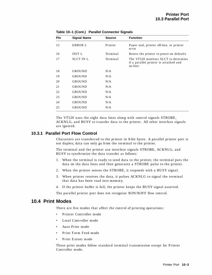
Printer Port10.3 Parallel Port
Table 10–1 (Cont.) Parallel Connector Signals
Pin Signal Name Source Function
15 ERROR L Printer Paper end, printer off-line, or printererror
16 INIT L Terminal Resets the printer to power-on defaults
17 SLCT IN L Terminal The VT520 monitors SLCT to determineif a parallel printer is attached andon-line.
18 GROUND N/A
19 GROUND N/A
20 GROUND N/A
21 GROUND N/A
22 GROUND N/A
23 GROUND N/A
24 GROUND N/A
25 GROUND N/A
The VT520 uses the eight data lines along with control signals STROBE,ACKNLG, and BUSY to transfer data to the printer. All other interface signalsare ignored.
10.3.1 Parallel Port Flow ControlCharacters are transferred to the printer in 8-bit bytes. A parallel printer port isnot duplex; data can only go from the terminal to the printer.
The terminal and the printer use interface signals STROBE, ACKNLG, andBUSY to synchronize the data transfer as follows:
1. When the terminal is ready to send data to the printer, the terminal puts thedata on the data lines and then generates a STROBE pulse to the printer.
2. When the printer senses the STROBE, it responds with a BUSY signal.
3. When printer receives the data, it pulses ACKNLG to signal the terminalthat data has been read into memory.
4. If the printer buffer is full, the printer keeps the BUSY signal asserted.
The parallel printer port does not recognize XON/XOFF flow control.
10.4 Print ModesThere are five modes that affect the control of printing operations:
• Printer Controller mode
• Local Controller mode
• Auto Print mode
• Print Form Feed mode
• Print Extent mode
These print modes follow standard terminal transmission except for PrinterController mode.
Printer Port 10–3

Printer Port10.4 Print Modes
10.4.1 Printer Controller ModeWhen printer controller mode is enabled, all data received at the host port ispassed through to the printer port, except for:
XON/XOFF when XON/XOFF flow control is enabled at either the host portor the printer portNUL when Ignore NUL characters is selected in the communication setup.
If printer-to-host communication is enabled, then all data received at the printerport is passed through to the host port with the exceptions listed previously.
10.5 Print OperationThe VT520 supports the following print operations:
• Print Line
• Print Page or Scrolling Region
• Print Screen
Print Screen prints the screen as it appears, including the status lines if enabled.Print Screen, however, does not print the keyboard indicator line.
10.6 Transmitting Print DataUsers have three choices for a printer type:
• DEC ANSI
• IBM ProPrinter
• DEC + IBM emulation mode
Depending on the printer type selected, the terminal transmits different controlfunctions to the printer. You can select the printer type in Set-Up or by using theescape sequence, DECSPRTT.
10.6.1 DEC ANSIThe DEC ANSI protocol supports the following printed data types:
• When in 8-bit mode:
ASCII only
ASCII + Line Drawing
• When in 7-bit mode:
National only
National + Line Drawing
You select a printed data type based on the 7- or 8-bit printer port setting and thecharacter set capability of the attached printer. The VT520 sends initialization,transmission, and closing sequences according to the printed data type selected.
If IBM PC characters are displayed, then the terminal translates thecorresponding characters in the ISO Latin-1 character set and transmits thembased on the current printed data type selected. If there is no correspondingcharacter in ISO Latin-1, then the Space character is used instead.
10–4 Printer Port

Printer Port10.6 Transmitting Print Data
10.6.2 IBM ProPrinter or Compatible PrinterWhen an IBM ProPrinter is attached, the terminal sends IBM ProPrintersequences. You can neither designate, nor invoke the ANSI sequence or any otheroperating sequences in this mode.
The VT520 supports the following printer character sets for the IBM printer:PC Multilingual, PC Latin 2 (PC Slavic), PC International, PC Spanish, PCPortuguese, PC Danish, PC French Canadian, PC Hebrew, PC Greek, PCTurkish, and PC Cyrillic.
During initialization, the VT520 sends a control sequence to the printer toselect the same code page as the printer character set selected in the terminal.You must select the appropriate printer character set for the correct data to beprinted either in Set-Up or by the escape sequence, DECSPPCS.
In an IBM ProPrinter, each code page has the following character sets:
Character Set 1Character Set 2Same as receiveAll Characters
The character sets are identical, except for the interpretation of C0 (0/0 through1/15) and C1 (8/0 through 9/15) characters.
In Character Set 1, the controls in C0 are identical to those in C1, except that 80(hex) is ignored instead of being interpreted as NUL.
Character Set 2 uses the same controls as C0, except that some printablecharacters are added to unused character code spaces. The C1 region is allprintable characters.
Same as receive uses IBM ProPrinter sequences with control codes or withouthost control codes.
The ‘‘All Characters’’ set only has printable characters. No control codes areallocated to this character set.
The VT520 initializes the printer to use Character Set 2 at the start of a printscreen operation. When a C0 printable character is encountered, the VT520 sendsthe appropriate sequence to print from the ‘‘All Characters’’ set. See the Set-Upchapter for detailed description on selecting these character sets.
10.6.2.1 Data TransmissionThe printer is either an IBM personal printer or a compatible printer. Itrecognizes the IBM ProPrinter mode escape sequences and supports theterminal’s code pages. The printer should support a software-selectable codepage switching sequence. If it does not, then you need to take appropriate actionto set the correct code page before a printing operation takes place.
Printer Port 10–5
Printer Port10.6 Transmitting Print Data
Each time a print operation is requested, the VT520 sends the following escapesequences:
Escape Sequence Meaning
ERSCS Selects code page
ERC02 Selects Character Set 2
Characters are sent to the printer along with their display attributes. If aC0 printable character is encountered, the VT520 sends the escape sequence,ERSSACS or ERC0ACS, to print from the "All Characters" set. If a characterthat is not in the selected code page is encountered, then a Space character issent instead.
The VT520 supports the following display attributes sequences:
Display AttributeSequence Meaning
EREDHW Sets double-height and width
EREBD Enables bold
ERDBD Disables bold
EREUL Sets underline
ERDUL Resets underline
The VT520 supports the following character set switching sequences:
SwitchingSequence Meaning
ERSSACS Prints a single character from "All Characters" set
ERC0ACS Prints multiple characters from "All Characters" set
If the terminal has DEC Supplemental or ISO Latin 1 characters on the screen,then the VT520 translates the characters to corresponding characters in the codepage indicated by the printer character set before the transmission takes place. Ifthere is no corresponding character in the selected IBM code page, then the Spacecharacter is used instead.
The line and display attributes of the printer should be switched back to thedefault state when printing is completed.
10.6.3 DEC ANSI with IBM ProPrinter EmulationYou can specify both DEC ANSI printed data types and IBM ProPrinter PCcharacter sets in Set-Up when this type of printer is selected. If the terminalis set to display DEC or ISO character sets, then the VT520 treats the printeras a DEC ANSI printer and transmits data to the attached printer using ANSIprotocols.
If the terminal is set to display PC character sets, then the VT520 transmits datato the attached printer using the IBM ProPrinter protocol. During initialization,the VT520 sends a Select Other Coding System (SOCS) sequence followed byDECIPEM sequence to the printer to force the printer into IBM ProPrinteremulation mode. The terminal sends all other sequences just as in the IBMProPrinter mode.
10–6 Printer Port
Printer Port10.6 Transmitting Print Data
10.6.3.1 Data TransmissionThe printer is a DEC ANSI printer with IBM ProPrinter emulation. The printeris in its default ANSI mode state. The printer recognizes IBM ProPrinter modeescape sequences and supports the IBM code pages. The printer supports thesoftware selectable code page switching sequence. If it does not, then you musttake appropriate action to set the correct code page before a printing operationtakes place.
Each time a print operation is requested, the VT520 sends the following escapesequences to initialize the attached printer to a known state:
Escape Sequences Function
SOCS Enters IBM ProPrinter mode
DECIPEM Enters IBM ProPrinter mode
ERSCS Selects code page
ERC02 Selects Character Set 2
The line and display attributes of the printer return to the default state whenprinting is completed by sending the following sequences:
Sequence Function
ROCS Returns from other coding system
DECIPEM Returns from IBM emulation mode
10.7 Printer StatusThe Session Management Extension is supported, so the terminal responds with"Printer Busy" and "Printer Not Assigned."
If the printer stalls, the word "Printer" flashes continuously in the IndicatorStatus Line.
10.8 Suspending Print OperationsEntering Set-Up can suspend, but not abort, printing operations. Upon exitfrom Set-Up, all unfinished printing operations resume unless an explicitaction has been taken in Set-Up to abort the print operation, such as Clearcommunications, Reset terminal, or Restore factory defaults.
10.9 Aborting Print OperationsThe Clear communications function from Set-up, aborts the current printoperation, clears the output silo, and re-initializes the printer port UART. Thisfunction may be used to get out of a "hung" state.
Note
After a Clear communications command, printing may not stopimmediately because characters may still be in the printer’s input buffer.
Printer Port 10–7

Part IIIVT520 ASCII Emulation
This part contains the following chapters:
• Chapter 11, ASCII Emulations and Control Functions
• Chapter 12, ASCII Escape Sequences
• Chapter 13, Defining and Loading ASCII Character Fonts


11ASCII Emulations and Control Functions
This chapter describes the ASCII emulations and control functions.
11.1 OverviewThe VT520 video terminal includes emulations for several popular ASCIIvideo terminals. ASCII terminals represent the other major class of serialasynchronous video terminals in widespread use today. Like the VT100, theseterminals communicate with a host computer by transmitting and receiving adata stream of 7-bit or 8-bit coded characters. To communicate successfully, thecomputer and the terminal use a convention for interpreting this data stream.This convention specifies how to recognize characters in the data stream as wellas how to recognize control information, such as formatting or editing commands.ASCII terminals support the ASCII character set, American Standard Code forInformation Interchange, ANSI X3.4; however, they do not follow other ANSIstandards that define controls for use with the ASCII character set. The originalASCII terminal protocol pre-dates the ANSI standards. These early protocolshave since been widely copied and extended to form the ASCII terminal market.
11.2 ASCII EmulationsThe VT520 includes a protocol emulation for the WYSE 325 color mode, WYSE160 Native mode, WYSE 60 Native mode, and many of its popular emulations ofother ASCII terminals:
• WYSE 325
• WYSE 160/60 Native mode
• WYSE PCTerm
• WYSE 50/50+
• WYSE 150/120
• Televideo 950
• Televideo 925
• Televideo 910+
• ADDS VP A2
Emulation means that virtually all host application programs designed for theseterminals will function correctly.
Note that the VT520 video terminal cannot be identical to all of these terminalssimultaneously, and the VT520 includes enhancements in its user interface andcharacter handling ability. The VT520 can handle additional languages andkeyboards that extend beyond the original terminals being emulated.
ASCII Emulations and Control Functions 11–1

ASCII Emulations and Control Functions11.2 ASCII Emulations
The VT520 does not emulate the graphics modes of the WYSE 160, such as theTEK 4010/4014 personality.
11.2.1 Enhanced ModeWYSE 160 Native mode includes function sequences for almost all featuressupported by the WYSE 160 terminal, including those supported by individualsub-emulations, such as Televideo or ADDS. When one of these sub-emulationsis selected, WYSE Enhanced mode (EnH) allows WYSE Native mode sequencesto be used from within a sub-emulation to access features that are not normallysupported by the physical terminal being emulated. This capability allowsexisting applications, for one of these emulated terminals, to be enhanced to takeadvantage of WYSE Native mode features. This enhanced mode does not apply tothe VT or ANSI modes, which follow the corresponding ANSI standards.
11.3 Coding NotationSince ASCII control functions do not follow a structured syntax, the notation usedto describe function sequences and parameters is important to avoid confusion.Escape sequences are shown with a space between each character to make themeasier to read. These spaces are not part of the Escape sequence.
Words in all caps: Strings of two or more capital letters, such as ESC orSPACE, are used as symbols, usually to represent a single character within anEscape sequence.
Words in italics: Words or abbreviations of two or more characters in italicsrepresent sequence parameters that are described subsequently.
Single characters: Single characters, such as "E" or "8", represent thecorresponding ASCII character in the sequence.
Regular text (upper- and lowercase): Regular text is sometimes used todescribe sequences that are similar or related to other sequences.
Table 11–1 lists the symbols used in the ASCII control functions.
Table 11–1 Symbols Used in ASCII Terminal Escape Sequences
Symbol Meaning Symbol Meaning
Ctrl- Ctrl immediately followed bya single character represents acontrol character in the range of0/0 to 1/15.
EnH Enhance Mode: This is the sameas the WYSE native code whenEnhance Mode is on.
Same Same as the WYSE native code(code is native to this emulation).
Wyse Same as the WYSE native code(code is not native to thisemulation, but is a WYSEenhancement).
n/a Not available in this emulation.
(continued on next page)
11–2 ASCII Emulations and Control Functions

ASCII Emulations and Control Functions11.3 Coding Notation
Table 11–1 (Cont.) Symbols Used in ASCII Terminal Escape Sequences
Symbol Code Symbol Code
NUL 0/0 DLE 1/0
SOH 0/1 DC1(XON)
1/1
STX 0/2 DC2 1/2
ETX 0/3 DC3(XOFF)
1/3
EOT 0/4 DC4 1/4
ENQ 0/5 NAK 1/5
ACK 0/6 SYN 1/6
BEL 0/7 ETB 1/7
BS 0/8 CAN 1/8
HT 0/9 EM 1/9
LF 0/10 SUB 1/10
VT 0/11 ESC 1/11
FF 0/12 FS 1/12
CR 0/13 GS 1/13
SO 0/14 RS 1/14
SI 0/15 US 1/15
SPACE 4/0
11.3.1 Communication Flow Control with PCTerm ModeXON/XOFF transmit flow control is disabled while in PCTerm mode. This meansXON and XOFF characters received from the host are ignored or displayed ascharacters from a PC character set. In PCTerm mode, the keyboard generatesscan codes. There are no multi-character reports (escape sequences or paste data)sent from the terminal. The terminal can still send XPC as receive flow control.
When switching out of PCTerm mode, the XON/XOFF state of thecommunications link is unknown. If XON/XOFF flow control is enabled, thenthe terminal shall transmit a single XON and clear the XOFF received state.
11.3.2 Protecting DataTurning on Write-Protect mode does not start protecting the data. It only definesthe range of data that needs to be protected. Not until Protect mode is turnedon does the data become protected. Changing emulation does not change theWrite-Protect mode. Characters range from 1/0 to 1/15, and embedded attributesare automatically write-protected even when Write-Protect mode is off.
To protect a certain area of data in the screen, users should:
1. Turn on Write-Protect mode.
2. Turn off Write-Protect mode, if the protected area has been defined.
3. Turn on Protect mode.
ASCII Emulations and Control Functions 11–3

ASCII Emulations and Control Functions11.3 Coding Notation
Protect Mode On: The protect condition usually is valid for the current pageonly. The exception is when Autopage mode is on, if a cursor movement commandcauses the cursor to move from one protected page to an unprotected page, theunprotected page becomes protected. If a cursor movement command causes thecursor to move from an unprotected page to a protected page, then the protectedpage becomes unprotected. Table 11–2 lists these commands.
Table 11–2 Commands that may Carry Protect Mode Features through Pages
Command Sequence
Cursor left (backspace) Ctrl/H
Cursor left (delete) DEL
Cursor right Ctrl/L
Cursor up; Scroll ESC j
Cursor down; Scroll (linefeed) Ctrl/J
Cursor to start of next line Ctrl/_
Tabulate cursor ESC i or Ctrl/I
Backtab ESC I
• Turning on Protect mode enables Line Edit mode. The terminal ignores thecommand to enable Page Edit mode. Editing command activities are limitedto the unprotected data. Any protected line can neither be inserted nor bedeleted.
• No cursor movement commands can cause data, protected or unprotected, toscroll off the page.
• The tabulation cursor becomes the field tab.
• Changing emulation turns off Protect mode, except when changing theterminal to a TVI emulation; in which case, the Protect mode does notchange.
• Some cursor commands can move the cursor into the protected area, somecannot.
Table 11–3 lists the commands that can move the cursor to the protectedarea. Even if the cursor can be moved into the protected area by executingthese commands, no data can be written into the area. The cursor jumps tothe first unprotected position when data started writing into the screen.
Table 11–4 lists the commands that cannot move the cursor to the protectedarea. Any attempt to move the cursor to the protected area by executing thesecommands, moves the cursor up, down, left, or right into the first unprotectedposition.
11–4 ASCII Emulations and Control Functions

ASCII Emulations and Control Functions11.3 Coding Notation
Table 11–3 Commands that Can Move the Cursor to Protected Area
Move Cursor . . . Sequence
Up; scroll (reverse linefeed) ESC j
Down; no scroll Ctrl/V
To specific line ESC [ line
To a specific column ESC_column
In current page ESC = line col
To a specific page ESC h page
In specific 80-column page ESC w @ page line col
In specific 80-column window ESC - wnd/page line col
In 80/132-column current page ESC a ll R ccc C
Table 11–4 Commands that Cannot Move Cursor into Protected Area
Move Cursor . . . Sequence
Left (backspace) Ctrl/H †
Left (delete) DEL
Right Ctrl/L
Up; No scroll Ctrl/K †‡
Down; Scroll (linefeed) Ctrl/J
To start of line Ctrl/M
To start of next line Ctrl/_
Home ESC { or Ctrl/^
†The cursor can be moved to a protected field under certain conditions. Refer to the specific cursorcommand section for details.‡Cursor can be moved to a protected field for TVI personalities.
ASCII Emulations and Control Functions 11–5


12ASCII Escape Sequences
This chapter summarizes the ASCII escape and control Sequences that the VT520recognizes when it is operating in its ASCII emulation modes.
12.1 ASCII CommunicationsTable 12–1 lists the serial port control functions for each mode. The word ‘‘same’’in Table 12–1 signifies the same control sequence as the WYSE 325/160/60column.
Table 12–1 Serial Port Control Functions
WYSE TVI ADDS
ACK Mode 325/160/60 PCTerm 150/120 50/50+ 950 925 910+ A2
ACK Mode On (default) ESC e 7 n/a same same EnH EnH EnH EnHACK Mode Off ESC e 6 n/a same same EnH EnH EnH EnH
Answerback Mode
Answerback Off (default) ESC e Sp n/a same n/a n/a n/a EnHAnswerback On ESC e ! n/a same same n/a n/a n/a n/aAnswerback Message ESC c ; answer Ctrl/Y
ESC ] answer Ctrl/Msame same n/a n/a n/a EnH
Send Answerbackmessage – Format 1: ESC c < n/a same same n/a n/a n/a EnH
Format 2: Ctrl/E same same same same same same EnHConceal Answerback ESC c = n/a same same n/a n/a n/a EnH
Assign Serial Ports
S1=comm1 (host) ESC e 8 n/a same same EnH EnH EnH EnHS1=comm2 (host) ESC e 9 n/a same same EnH EnH EnH EnH
Monitor Mode
Monitor Mode Off(default)
ESC u orESC X
same same same same same same EnH onor off
Monitor Mode On ESC U same same same same same same EnH
(continued on next page)
ASCII Escape Sequences 12–1
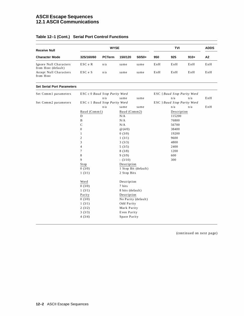
ASCII Escape Sequences12.1 ASCII Communications
Table 12–1 (Cont.) Serial Port Control Functions
Receive NullWYSE TVI ADDS
Character Mode 325/160/60 PCTerm 150/120 50/50+ 950 925 910+ A2
Ignore Null Charactersfrom Host (default)
ESC e R n/a same same EnH EnH EnH EnH
Accept Null Charactersfrom Host
ESC e S n/a same same EnH EnH EnH EnH
Set Serial Port Parameters
Set Comm1 parameters ESC c 0 Baud Stop Parity Word ESC { Baud Stop Parity Wordn/a same same n/a n/a EnH
Set Comm2 parameters ESC c 1 Baud Stop Parity Word ESC } Baud Stop Parity Wordn/a same same n/a n/a EnH
Baud (Comm1) Baud (Comm2) DescriptionD N/A 115200B N/A 76800C N/A 567000 @ (4/0) 384001 0 (3/0) 192002 1 (3/1) 96003 3 (3/3) 48004 5 (3/5) 24007 8 (3/8) 12008 9 (3/9) 6009 : (3/10) 300Stop Description0 (3/0) 1 Stop Bit (default)1 (3/1) 2 Stop Bits
Word Description0 (3/0) 7 bits1 (3/1) 8 bits (default)Parity Description0 (3/0) No Parity (default)1 (3/1) Odd Parity2 (3/2) Mark Parity3 (3/3) Even Parity4 (3/4) Space Parity
(continued on next page)
12–2 ASCII Escape Sequences

ASCII Escape Sequences12.1 ASCII Communications
Table 12–1 (Cont.) Serial Port Control Functions
WYSE TVI ADDS
Serial Port Handshaking 325/160/60 PCTerm 150/120 50/50+ 950 925 910+ A2
Set Comm1 Receive ESC c 2 Handshakingn/a same same n/a n/a n/a EnH
Set Comm2 Receive ESC c 3 Handshakingn/a same same n/a n/a n/a EnH
Set Comm1 Transmit ESC c 4 Handshakingn/a same same n/a n/a n/a EnH
Set Comm2 Transmit ESC c 5 Handshakingn/a same same n/a n/a n/a EnH
Handshaking Receive Flow Control Transmit Flow Control0 None None (default)1 XON-XOFF/XPC (default) XON/XOFF2 DTR DSR3 XON-XOFF/XPC and DTR XON/XOFF and DSR
Set Host port Receiveto DTR
n/a Ctrl/N n/a n/a Ctrl/N Ctrl/N Ctrl/N n/a
Set Host port Receiveto XON/XOFF or XPC
n/a Ctrl/O n/a n/a Ctrl/O Ctrl/O Ctrl/O n/a
Set Duplex Mode
Full-Duplex On (default) ESC D F ESC } same same same same same EnHHalf-Duplex On ESC D H ESC { same same same same same EnH
Set Block Mode
Block Mode Off (default) ESC C same same same Wyse Wyse Wyse EnHBlock Mode On ESC B same same same same same or
ESC csame orESC c
EnH
Set Local Mode
Set Local Mode n/a n/a n/a n/a ESC c n/a n/a n/a
Set Maximum Transmit Rate Limit
Transmit Speed ESC c 6 Max n/a same same n/a n/a n/a EnHFunction Keys ESC c 7 Max n/a same same n/a n/a n/a EnH
Max Characters Per Second0 301 502 No Limit (default)3 150
ASCII Escape Sequences 12–3

ASCII Escape Sequences12.2 Terminal Management
12.2 Terminal ManagementTable 12–2 lists the terminal management control functions. The word ‘‘same’’in Table 12–2 signifies the same control sequence as in the WYSE 325/160/60column.
Table 12–2 Terminal Management Control Functions
Select TerminalWYSE TVI ADDS
Personality 325/160/60 PCTerm 150/120 50/50+ 950 925 910+ A2
ADDS VP A2 ESC ~ % ESC v%
same as325/160/60
same Wyse Wyse Wyse Wyse
TVI 950 ESC ~ ( ESC v ( same same Wyse Wyse Wyse WyseTVI 925 ESC ~ $ ESC v $ same same Wyse Wyse Wyse WyseTVI 910 ESC ~ # ESC v # same same Wyse Wyse Wyse WyseVT520, 7-bit ESC ~ < ESC v < same same Wyse Wyse Wyse WyseVT520, 8-bit ESC ~ = ESC v = same same Wyse Wyse Wyse WyseVT100 ESC ~ ; ESC v ; same same Wyse Wyse Wyse WyseVT52 ESC ~ 6 ESC v 6 same same Wyse Wyse Wyse WyseWYSE 160/60 ESC ~ 4 ESC v 4 same same Wyse Wyse Wyse WyseWYSE 160/60 PCTerm ESC ~ 5 ESC v 5 same same Wyse Wyse Wyse WyseWYSE 150/120 ESC ~ 4 ESC v 4 same same Wyse Wyse Wyse WyseWYSE 50+ ESC ~ " ESC v " same same Wyse Wyse Wyse Wyse
Send Terminal ID
Inquire emulation ID ESC Sp n/a same same ESC M ESC M ESC M EnHEmulation Response Response in Column/Row FormatWYSE 160/60 160 (3/1 3/6 3/0 0/13)WYSE 150/120 160 (3/1 3/6 3/0 0/13)WYSE 50+ 50 (3/5 3/0 0/13)ADDS VPA2 160 (3/1 3/6 3/0 0/13)TVI 910+ 925 REV I (3/9 3/2 3/5 2/0 5/2 4/5 5/6 2/0 4/9 0/13)TVI 925 925 REV I (3/9 3/2 3/5 2/0 5/2 4/5 5/6 2/0 4/9 0/13)TVI 950 1.0 (3/1 2/14 3/0 2/0 0/13)
Set Enhanced Mode
Enhanced Mode On(default)
ESC ~ ! ESC v ! same same Wyse Wyse Wyse Wyse
Enhanced Mode Off ESC ~ Sp ESC vSp
same same Wyse Wyse Wyse Wyse
Save Set-Up Modes
To NVM (except Tabs) ESC c V n/a same same n/a n/a n/a EnHTo NVM with Tabs ESC c W n/a same same n/a n/a n/a EnH
(continued on next page)
12–4 ASCII Escape Sequences

ASCII Escape Sequences12.2 Terminal Management
Table 12–2 (Cont.) Terminal Management Control Functions
WYSE TVI ADDS
Select Terminal Defaults 325/160/60 PCTerm 150/120 50/50+ 950 925 910+ A2
PCTerm Mode Group1 n/a ESC m n/a n/a n/a n/a n/a n/aAll Modes2 ESC c T n/a same same n/a n/a n/a EnHPower On Reset ESC c X n/a same same n/a n/a n/a EnH
Load/Send Time of Day
Load Time of Day3 ESC c 8 Hr MinESC Sp 1 a/p Hr Min
same same ESC Sp 1 a/p Hr Min EnH
Send Time of Day n/a ESC Sp2
n/a n/a ESC Sp2
ESC Sp2
ESC Sp2
n/a
1Sets the following parameters for PCTerm mode:
• Autoscroll = On• Received CR = CR• Communication Mode = Full Duplex• Enhanced Mode = Off• Wrap EOL = Off• Attribute = Char2Sets the parameters shown in Table 11-2.3Hour ranges from 00 to 23; Minute ranges from 00 to 59 decimal. Entering "00" in hour is displayed as 12 AM. The a/pis a single character—a = AM, p = PM.
12.3 Keyboard ProcessingTable 12–3 lists the keyboard processing control functions. The word ‘‘same’’in Table 12–3 signifies the same control sequences as in the WYSE 325/160/60column.
Table 12–3 Keyboard Processing Control Functions
WYSE TVI ADDS
Locking the Keyboard 325/160/60 PCTerm 150/120 50/50+ 950 925 910+ A2
Unlock keyboard (default) Ctrl/N or ESC " same same ESC " ESC " ESC " Ctrl/BESC " ESC 6
Lock keyboard Ctrl/O or ESC # same same ESC # ESC # ESC # Ctrl/DESC # ESC 5
Enable/Disable Key Repeat
Key Repeat On (default) ESC e - n/a same same EnH EnH EnH EnHKey Repeat Off ESC e , n/a same same EnH EnH EnH EnH
(continued on next page)
ASCII Escape Sequences 12–5

ASCII Escape Sequences12.3 Keyboard Processing
Table 12–3 (Cont.) Keyboard Processing Control Functions
WYSE TVI ADDS
Caps Lock 325/160/60 PCTerm 150/120 50/50+ 950 925 910+ A2
Caps Lock off ESC e ´ ESC SpM
same same EnH EnH EnH EnH
Caps Lock on ESC e & ESC SpL
same same EnH EnH EnH EnH
Lock key=Caps Lock(default)
ESC e T n/a same same EnH EnH EnH EnH
Lock key=Shift Lock ESC e V n/a same same EnH EnH EnH EnH
Lock key=Reverse Lock ESC e U n/a same same EnH EnH EnH EnH
Num Lock
Num Lock off ESC e @ ESC SpK
same same EnH EnH EnH EnH
Num Lock on ESC e A ESC SpJ
same same EnH EnH EnH EnH
Scroll Lock
Scroll Lock off ESC e B ESC SpO
same same EnH EnH EnH EnH
Scroll Lock on ESC e C ESC SpN
same same EnH EnH EnH EnH
Keycode Mode
ASCII Key Codes1 ESC e H ESC c same same EnH EnH EnH EnH
PC Scan Codes ESC e I ESC H same same EnH EnH EnH EnH
Request Modifier Keys Status
Inquiry n/a ESC [ n/a n/a n/a n/a n/a n/aReport: 81(Hex) + awhere a indicates the modifier key being pressed as follows:Bit Modifier Key0 Caps lock1 Always 02 Always 03 Scroll lock On4 Alt5 Ctrl6 Num lock On7 Shift key
WYSE TVI ADDS
Margin Bell 325/160/60 PCTerm 150/120 50/50+ 950 925 910+ A2
1Default for all but PCTerm mode.
(continued on next page)
12–6 ASCII Escape Sequences
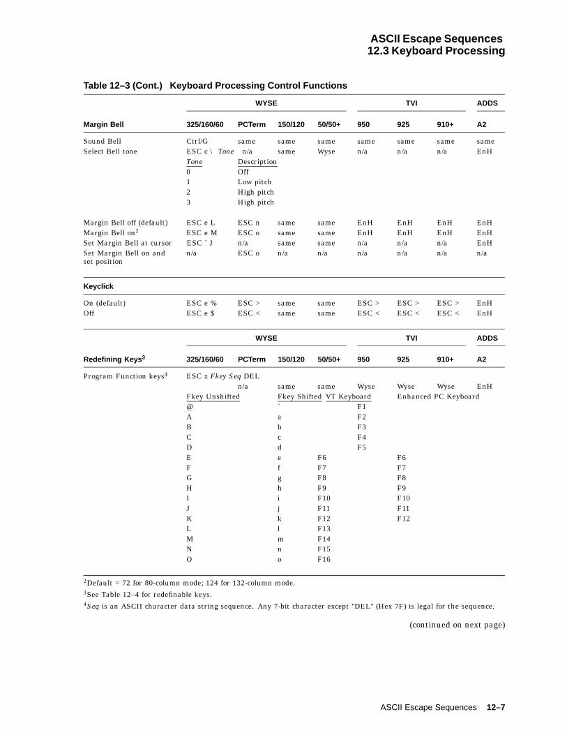
ASCII Escape Sequences12.3 Keyboard Processing
Table 12–3 (Cont.) Keyboard Processing Control Functions
WYSE TVI ADDS
Margin Bell 325/160/60 PCTerm 150/120 50/50+ 950 925 910+ A2
Sound Bell Ctrl/G same same same same same same sameSelect Bell tone ESC c \ Tone n/a same Wyse n/a n/a n/a EnH
Tone Description0 Off1 Low pitch2 High pitch3 High pitch
Margin Bell off (default) ESC e L ESC n same same EnH EnH EnH EnHMargin Bell on2 ESC e M ESC o same same EnH EnH EnH EnHSet Margin Bell at cursor ESC ` J n/a same same n/a n/a n/a EnHSet Margin Bell on andset position
n/a ESC o n/a n/a n/a n/a n/a n/a
Keyclick
On (default) ESC e % ESC > same same ESC > ESC > ESC > EnHOff ESC e $ ESC < same same ESC < ESC < ESC < EnH
WYSE TVI ADDS
Redefining Keys 3 325/160/60 PCTerm 150/120 50/50+ 950 925 910+ A2
Program Function keys4 ESC z Fkey Seq DELn/a same same Wyse Wyse Wyse EnH
Fkey Unshifted Fkey Shifted VT Keyboard Enhanced PC Keyboard@ ` F1A a F2B b F3C c F4D d F5E e F6 F6F f F7 F7G g F8 F8H h F9 F9I i F10 F10J j F11 F11K k F12 F12L l F13M m F14N n F15O o F16
2Default = 72 for 80-column mode; 124 for 132-column mode.3See Table 12–4 for redefinable keys.4Seq is an ASCII character data string sequence. Any 7-bit character except "DEL" (Hex 7F) is legal for the sequence.
(continued on next page)
ASCII Escape Sequences 12–7

ASCII Escape Sequences12.3 Keyboard Processing
Table 12–3 (Cont.) Keyboard Processing Control Functions
WYSE TVI ADDS
Program Key Direction 325/160/60 PCTerm 150/120 50/50+ 950 925 910+ A2
WYSE TVI ADDS
Program Key Direction 325/160/60 PCTerm 150/120 50/50+ 950 925 910+ A2
Program Key Direction ESC Z Dir Key Seq DEL same same Wyse Wyse EnHESC | FKey Dir Seq Ctrl-Y ESC | FKey Dir Seq Ctrl-Y
Key-Sent direction Communication Mode Key Definition is Sent to . . .Local Terminal screen onlyRemote Host onlyNormal Depending on Comm mode:
Full-duplex Host onlyHalf-duplex Both the host and the terminal screenBlock Terminal screen onlyHalf Block Both the host and the terminal screen
Dir Key Transmission Direction0 Normal1 Remote (default)2 Local3 Normal (TVI950 and WYSE 325/160/60
PCTerm only)
WYSE TVI ADDS
Inquire Key Direction 325/160/60 PCTerm 150/120 50/50+ 950 925 910+ A2
Inquiry: ESC Z ~ Key n/a same same n/a Wyse Wyse EnH
Response: Dir Key Sequence DEL
Clear Key Definitions
Clear Function keydirection and definition
ESC z Fkey DEL n/a same same Wyse Wyse Wyse EnH
Set key direction andClear key definition
ESC Z Dir Key DEL
n/a same same n/a Wyse Wyse EnHClear all redefinable keydefinitions
ESC c U n/a same same n/a n/a n/a EnH
12–8 ASCII Escape Sequences

ASCII Escape Sequences12.3 Keyboard Processing
Table 12–4 lists the redefinable keys.
Table 12–4 Redefinable Keys
Emulation Redefinable Keys
WYSE 325/160/60, WYSE150/120, WYSE 50+,TVI925, and TVI 910
Unshifted Shifted VT Keyboard EPC Keyboard
SP % ESC! & Tab Tab" ´ Backspace Backspace# ( Remove$ ) Return Enter* / Select Home+ 0 * *
, 1 + +
- 2 ( (
. 3 ) )
s 4 Enter Enter (keypad)q p PF4 Insertr w Page Down} z PF35 6 PF2 Delete7 8 PF1R X Print Screen: ; Page Up\ ] EndQ W F17S Y F18T Z F19P V F20
WYSE 325/160/60PCTerm
Fkey Unshifted VT Keyboard EPC Keyboard
1 ! F1 F12 @ F2 F23 # F3 F34 $ F4 F45 % F5 F56 ^ F6 F67 & F7 F78 * F8 F89 ( F9 F90 ) F10 F10
(continued on next page)
ASCII Escape Sequences 12–9
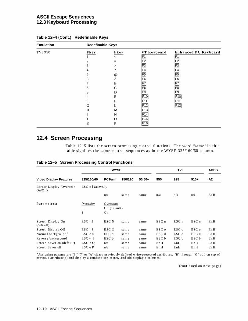
ASCII Escape Sequences12.3 Keyboard Processing
Table 12–4 (Cont.) Redefinable Keys
Emulation Redefinable Keys
TVI 950 Fkey Fkey VT Keyboard Enhanced PC Keyboard1 < F1 F12 = F2 F23 > F3 F34 ? F4 F45 @ F5 F56 A F6 F67 B F7 F78 C F8 F89 D F9 F9: E F10 F10; F F11 F11G L F12 F12H M F13I N F14J O F15K P F16
12.4 Screen ProcessingTable 12–5 lists the screen processing control functions. The word ‘‘same’’ in thistable signifies the same control sequences as in the WYSE 325/160/60 column.
Table 12–5 Screen Processing Control Functions
WYSE TVI ADDS
Video Display Features 325/160/60 PCTerm 150/120 50/50+ 950 925 910+ A2
Border Display (OverscanOn/Off)
ESC c ] Intensity
n/a same same n/a n/a n/a EnH
Parameters: Intensity Overscan0 Off (default)1 On
Screen Display On(default)
ESC ` 9 ESC N same same ESC n ESC n ESC n EnH
Screen Display Off ESC ` 8 ESC O same same ESC o ESC o ESC o EnHNormal background1 ESC ^ 0 ESC d same same ESC d ESC d ESC d EnHReverse background ESC ^ 1 ESC b same same ESC b ESC b ESC b EnHScreen Saver on (default) ESC e Q n/a same same EnH EnH EnH EnHScreen Saver off ESC e P n/a same same EnH EnH EnH EnH
�Assigning parameters "6," "7" or "A" clears previously defined write-protected attributes. "B" through "G" add on top ofprevious attribute(s) and display a combination of new and old display attributes.
(continued on next page)
12–10 ASCII Escape Sequences
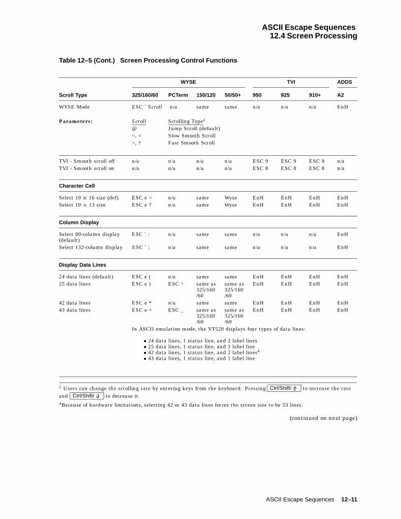
ASCII Escape Sequences12.4 Screen Processing
Table 12–5 (Cont.) Screen Processing Control Functions
WYSE TVI ADDS
Scroll Type 325/160/60 PCTerm 150/120 50/50+ 950 925 910+ A2
WYSE Mode ESC ` Scroll n/a same same n/a n/a n/a EnH
Parameters: Scroll Scrolling Type2
@ Jump Scroll (default)<, = Slow Smooth Scroll>, ? Fast Smooth Scroll
TVI - Smooth scroll off n/a n/a n/a n/a ESC 9 ESC 9 ESC 9 n/aTVI - Smooth scroll on n/a n/a n/a n/a ESC 8 ESC 8 ESC 8 n/a
Character Cell
Select 10 � 16 size (def) ESC e > n/a same Wyse EnH EnH EnH EnHSelect 10 � 13 size ESC e ? n/a same Wyse EnH EnH EnH EnH
Column Display
Select 80-column display(default)
ESC ` : n/a same same n/a n/a n/a EnH
Select 132-column display ESC ` ; n/a same same n/a n/a n/a EnH
Display Data Lines
24 data lines (default) ESC e ( n/a same same EnH EnH EnH EnH25 data lines ESC e ) ESC ^ same as
325/160/60
same as325/160/60
EnH EnH EnH EnH
42 data lines ESC e * n/a same same EnH EnH EnH EnH43 data lines ESC e + ESC _ same as
325/160/60
same as325/160/60
EnH EnH EnH EnH
In ASCII emulation mode, the VT520 displays four types of data lines:
� 24 data lines, 1 status line, and 2 label lines� 25 data lines, 1 status line, and 1 label line� 42 data lines, 1 status line, and 2 label lines4
� 43 data lines, 1 status line, and 1 label line
2 Users can change the scrolling rate by entering keys from the keyboard. Pressing Ctrl/Shift/ * to increase the rateand Ctrl/Shift/ + to decrease it.4Because of hardware limitations, selecting 42 or 43 data lines forces the screen size to be 53 lines.
(continued on next page)
ASCII Escape Sequences 12–11

ASCII Escape Sequences12.4 Screen Processing
Table 12–5 (Cont.) Screen Processing Control Functions
Fill Page with "H"sWYSE TVI ADDS
in PCTerm Mode 325/160/60 PCTerm 150/120 50/50+ 950 925 910+ A2
Fill page with "H"s n/a ESC F n/a n/a n/a n/a n/a n/a
Width-Change-Clear Mode
Width-change-clear off ESC e . n/a same same EnH EnH EnH EnHWidth-change-clear on(default)
ESC e / n/a same same EnH EnH EnH EnH
Page Size
Set Page Size5 ESC w Length same same ESC \ Length6 EnHESC \ Length6
WYSE 325/160/60, WYSE50+ Parameters:
Length Size of a Page Description
G 1*lines Page number = current screen data linesH 2*lines Page number = current screen data lines * 2I 4*lines Page number = current screen data lines * 4J * One page number = screen data lines; the other
contains rest of lines in memory.WYSE 325/160/60PCTerm and TVI
Length Size of a Page Description
Parameters: 1 1*lines Page number = current screen data lines2 2*lines Page number = current screen data lines * 23 4*lines Page number = current screen data lines * 44 * One page number = screen data lines; the other
contains rest of lines in memory.
Display Page
Display Previous Page7 ESC w Bor ESC J
n/a same same ESC J ESC J ESC J EnH
Display Next Page8 ESC w Cor ESC K
n/a same same ESC K ESC K ESC K n/a
Display Specific Page ESC w Page n/a same same n/a n/a n/a EnH
5 Upon receipt of the Set Page Size command, the terminal:
� Clears the display memory to NUL (0/0) characters.� Displays first page "page 0."� Moves the cursor to its home position.� Changes the split screen to a full screen format.� Turns off the Protect mode.� Unlocks the locked line.
6Enhanced Mode off.7 In WYSE mode, command "ESC J" works only when the screen is not split. If the screen is split, refer to "ActivateOther Window or Page" command. Command "ESC w B" in WYSE modes works when the screen is not split or the splitscreen is caused by an adjustable split. It does not work when the split screen is a result of a simple split. Users can uselocal function keys to display the previous page. On a VT keyboard, press Ctrl/Prev ; on an Enhanced PC keyboard, press
Ctrl/Page Up .8 Users can use a local function key to display the next page. Press Ctrl/N , where N is a number on the numeric keypadkey equivalent to the page number, on both VT and Enhanced PC keyboard.
(continued on next page)
12–12 ASCII Escape Sequences

ASCII Escape Sequences12.4 Screen Processing
Table 12–5 (Cont.) Screen Processing Control Functions
WYSE TVI ADDS
Split Screen 325/160/60 PCTerm 150/120 50/50+ 950 925 910+ A2
Split screen horizontally ESC x A Line n/a same same n/a n/a n/a n/aAdjustable horiz split ESC x C Line n/a same same n/a n/a n/a n/aSplit screen horizontallyand Clear data
ESC x 1 Line n/a same same n/a n/a n/a n/a
Adjustable horiz splitscreen and Clear data
ESC x 3 Line n/a same same n/a n/a n/a n/a
Lower horiz split ESC x P n/a same same n/a n/a n/a n/aRaise horiz split ESC x R n/a same same n/a n/a n/a n/a
Windows
Activate upper window ESC ] n/a same same n/a n/a n/a n/aActivate lower window ESC } n/a same same n/a n/a n/a n/aActivate other window orpage
ESC J orESC K
n/a same same n/a n/a n/a n/a
Roll window up in page ESC w E n/a same same n/a n/a n/a n/aRoll window down in page ESC w F n/a same same n/a n/a n/a n/aRedefine screen as onewindow
ESC x @ n/a same same n/a n/a n/a n/a
Redefine screen as onewindow and Clear page
ESC x 0 n/a same same n/a n/a n/a n/a
Cursor Drag Mode
Cursor drag mode on(default)
ESC d ) n/a same same n/a n/a n/a n/a
Cursor drag mode off ESC d ( n/a same same n/a n/a n/a n/a
Status Line Display
Editing Status line on ESC ` a n/a same same n/a n/a n/a EnHStandard Status line on(default)
ESC ` b n/a same same n/a n/a n/a EnH
Status line off ESC ` c n/a same same n/a n/a n/a EnHStarts at Column Standard Status Line Editing Status Line26 HH:MM AM (or PM) PROT (Protect mode is on)31 WRPT (Write protect is on)35 Column-Row (Cursor)36 INS (Insert mode is on)
Messages: Message DescriptionLOCK Keyboard lockedCOMP In compose processNUM NUM LOCK stateCAPS The Caps Lock key is on1... Page indication (No message displayed for page 0)* Monitor mode stateFDX Full-duplex modeHDX Half-duplex mode
(continued on next page)
ASCII Escape Sequences 12–13
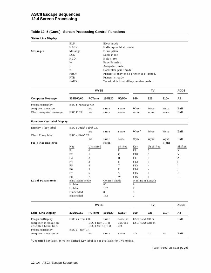
ASCII Escape Sequences12.4 Screen Processing
Table 12–5 (Cont.) Screen Processing Control Functions
Status Line Display
BLK Block modeHBLK Half-duplex block mode
Messages: Message DescriptionLCL Local modeHLD Hold state% Page Printing> Autoprint mode= Controller print modePBSY Printer is busy or no printer is attached.PTR Printer is ready.<AUX Terminal is in auxiliary receive mode.
WYSE TVI ADDS
Computer Message 325/160/60 PCTerm 150/120 50/50+ 950 925 910+ A2
Program/Display ESC F Message CRcomputer message n/a same same Wyse Wyse Wyse EnHClear computer message ESC F CR n/a same same same same same EnH
Function Key Label Display
Display F key label ESC z Field Label CRn/a same same Wyse9 Wyse Wyse EnH
Clear F key label ESC z Field CRn/a same same Wyse Wyse Wyse EnH
Field Parameters: Field FieldKey Unshifted Shifted Key Unshifted ShiftedF1 0 P F9 8 XF2 1 Q F10 9 YF3 2 R F11 : ZF4 3 S F12 ; [F5 4 T F13 < \F6 5 U F14 = ]F7 6 V F15 > ^F8 7 W F16 ? _
Label Parameters: Emulation Mode Column Mode Maximum LengthHidden 80 9Hidden 132 7Embedded 80 8Embedded 132 7
WYSE TVI ADDS
Label Line Display 325/160/60 PCTerm 150/120 50/50+ 950 925 910+ A2
Program/Display ESC z ( Text CR same same as ESC f text CR or EnHcomputer message onunshifted Label line.
ESC f text CR orESC f text Ctrl-M
325/160/60
ESC f text Ctrl-M
Program/Display ESC z ) text CRcomputer message on n/a same same n/a n/a n/a EnH
9Unshifted key label only; the Shifted Key label is not available for TVI modes.
(continued on next page)
12–14 ASCII Escape Sequences

ASCII Escape Sequences12.4 Screen Processing
Table 12–5 (Cont.) Screen Processing Control Functions
WYSE TVI ADDS
Label Line Display 325/160/60 PCTerm 150/120 50/50+ 950 925 910+ A2
shifted Label line.Clear unshifted Labelline.
ESC z ( CR ESC f CR sameor ESC f Ctrl-M
same as325/160/60
ESC f CR orESC f Ctrl-M
EnH
Clear shifted Label line. ESC z ) CR n/a same same n/a n/a n/a EnHDisable shifted Label line. ESC z DEL n/a same same n/a n/a n/a EnH
WYSE and ADDSEnhanced Modes:
There are two distinct label lines when the terminal is using 24 or 42 data lines:
• The upper one is for shifted label line (shifted function key label line).
• The lower one is for unshifted label line (unshifted function key label line).
When using the 25 or 43 data line configuration mode, only one label line is available at atime. By default, it displays the unshifted label line (or unshifted function key label line).This line becomes a shifted label line (or shifted function key label) whenever the Shift keyis pressed. Releasing the Shift key returns the line to be the unshifted display line.
TVI and PCTerm Modes:
Only an unshifted label line (unshifted function label line) is available. To be visible, thelabel line must be explicitly turned on by the command "Turn on User Line."
For TVI personalities, the label line is displayed only when data line is set to 24 or 42data lines.
For PCTerm mode, turning on the display line forces the terminal to 24 or 42 data lines.If the cursor is at the 25th or 43rd line before the line is set, then the cursor moves to thesame column at line 24 or 42, and the entire data area scrolls up one line. The label line isdisplayed at the 25th or 43rd line, respectively.
Text Parameter: The parameter text is a character string to be entered in the label line. The allowable sizeof text varies among emulation modes and column modes. In embedded emulation mode,the first character shown on the user line is an attribute space.Emulation Mode Column Mode Maximum Number Column PositionHidden 80 80 1—80Hidden 132 132 1—132Embedded 80 79 2—80Embedded 132 131 2—132
(continued on next page)
ASCII Escape Sequences 12–15
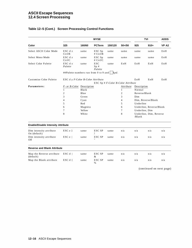
ASCII Escape Sequences12.4 Screen Processing
Table 12–5 (Cont.) Screen Processing Control Functions
WYSE TVI ADDS
Color 325 160/60 PCTerm 150/120 50+/50 925 910+ VP A2
Select ASCII Color Mode ESC d zCtrl/B
same ESC Sp# Ctrl/B
same same same same EnH
Select Mono Mode ESC d zCtrl/C
same ESC Sp# Ctrl/C
same same same same EnH
Select Color Palette ESC d zPalette
same ESCSp #Palette
same EnH EnH EnH EnH
##Palette numbers run from 0 to 9 and . kpd.
Customize Color Palette ESC d y F-Color B-Color Attribute EnH EnH EnHESC Sp # F-Color B-Color Attribute
Parameters: F- or B-Color Description Attribute Description1 Black 1 Normal2 Blue 2 Reverse/Blank3 Green 3 Dim4 Cyan 4 Dim, Reverse/Blank5 Red 5 Underline6 Magenta 6 Underline, Reverse/Blank7 Yellow 7 Underline, Dim8 White 8 Underline, Dim, Reverse
/Blank
Enable/Disable Intensity Attribute
Dim intensity attributeOn (default)
ESC e } same ESC SP!
same n/a n/a n/a n/a
Dim intensity attributeOff
ESC e | same ESC SP"
same n/a n/a n/a n/a
Reverse and Blank Attribute
Map the Reverse attribute(default)
ESC d | same ESC SP&
same n/a n/a n/a n/a
Map the Blank attribute ESC d { same ESC SP%
same n/a n/a n/a n/a
(continued on next page)
12–16 ASCII Escape Sequences

ASCII Escape Sequences12.4 Screen Processing
Table 12–5 (Cont.) Screen Processing Control Functions
User Label Line DisplayWYSE TVI ADDS
for TVI Mode 325/160/60 PCTerm 150/120 50/50+ 950 925 910+ A2
Turn off User line n/a ESC e or(default) ESC h same n/a ESC h ESC h ESC h n/aTurn on User line n/a ESC g n/a n/a ESC g ESC g ESC g n/a
Character Attributes
Assign character attribute(main display area)
ESC G Attr ESC GAttribute
same same same same same EnH
Parameters:Wyse 325,10 160/60, 150/120, 50+, and ADDS
Attr Display Attributes TVI Attr
SP Space character SP0 Normal 0, p1 Invisible10 1, q2 Blink 2, r3 Invisible and blink 3, s4 Reverse 4, t5 Reverse and invisible 5, u6 Reverse and blink 6, v7 Reverse, blink, invisible 7, w8 Underline 8, x9 Underline and invisible 9, y: Underline and blink :, z; Underline, blink, invisible ;, {< Underline and reverse <, |= Underline, reverse, invisible =, }> Underline, reverse, blink >, ~? Underline, reverse, blink, invisible ?, DELp Dimq Dim and invisibler Dim and blinks Dim, blink, invisiblet Dim and reverseu Dim, reverse, invisiblev Dim, reverse, blinkw Dim, reverse, blink, invisiblex Dim and underliney Dim, underline, invisiblez Dim, underline, blink{ Dim, underline, blink, invisible| Dim, underline, reverse} Dim, underline, reverse, invisible~ Dim, underline, reverse, blinkDEL Dim, underline, reverse, blink, invisible
† All the 7-bit ASCII codes are legal in this sequence. Example: "A" turns on the dim attribute, "T" turns on the reverseattribute, "S" turns on dim, blink and reverse attributes.
(continued on next page)
ASCII Escape Sequences 12–17

ASCII Escape Sequences12.4 Screen Processing
Table 12–5 (Cont.) Screen Processing Control Functions
PCTerm Mode Attribute Display Attributes
0, @, P, `, p Normal1, A, Q, a, q Invisible2, B, R, b, r Blink3, C, S, c, s Invisible and blink4, D, T, d, t Reverse5, E, U, e, u Reverse and invisible6, F, V, f, v Reverse and blink7, G, W, g, w Reverse, blink, invisible8, H, X, h, x Underline9, I, Y, i, y Underline and invisible:, J, Z, j, z Underline and blink;, K, [, k, { Underline, blink, invisible<, L \, l, | Underline and reverse=, M, ], } Underline, reverse, invisible>, N, ^, n, ~ Underline, reverse, blink?, O, _, o, DEL Underline, reverse, blink, invisible
SelectingWYSE TVI ADDS
Display Attribute Mode 325/160/60 PCTerm 150/120 50/50+ 950 925 910+ A2
Char attribute mode on11 ESC e 1 n/a same n/a n/a n/a n/a n/aChar attribute mode off ESC e 0 n/a same n/a n/a n/a n/a n/aPage attribute mode on12 ESC e 2 n/a same same EnH EnH EnH EnHLine attribute mode on ESC e 3 n/a same same EnH EnH EnH EnHAssign display attribute ESC A Area Attrto a message field n/a same same ESC \ Area Attr (EnH) EnHParameters: Area Description
0 Data Area1 Label Line2 Terminal message field on Status Line3 Computer message field on Status Line
Assign write-protectcharacter attribute
ESC `Wpca
n/a same same n/a n/a n/a EnH orESC 0Spca
Parameters usingWYSE sequences:�
Wpca Description Parameters -ADDS mode†
Spca Description
6 Reverse 0 Dim7 Dim (default) 1 BlinkA Normal 2 InvisibleB Blink 3 NormalC Invisible 4 ReverseE Underline 5 UnderlineF ReverseG Dim
�Assigning parameters "6," "7" or "A" clears previously defined write-protected attributes. "B" through "G" add on top ofprevious attribute(s) and display a combination of new and old display attributes.† All the 7-bit ASCII codes are legal in this sequence. Example: "A" turns on the dim attribute, "T" turns on the reverseattribute, "S" turns on dim, blink and reverse attributes.‡ Example: Dim + Reverse + Invisible reports VTS (8AH) + a.12Default for embedded emulation.
(continued on next page)
12–18 ASCII Escape Sequences
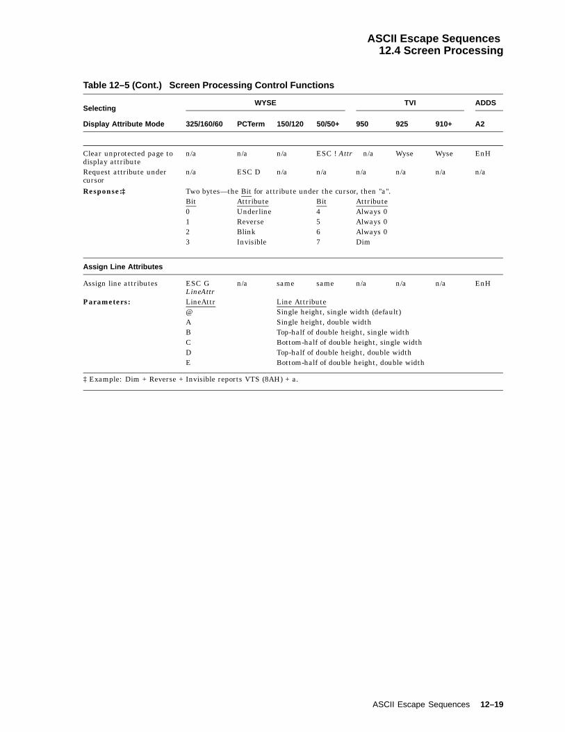
ASCII Escape Sequences12.4 Screen Processing
Table 12–5 (Cont.) Screen Processing Control Functions
SelectingWYSE TVI ADDS
Display Attribute Mode 325/160/60 PCTerm 150/120 50/50+ 950 925 910+ A2
Clear unprotected page todisplay attribute
n/a n/a n/a ESC ! Attr n/a Wyse Wyse EnH
Request attribute undercursor
n/a ESC D n/a n/a n/a n/a n/a n/a
Response:‡ Two bytes—the Bit for attribute under the cursor, then "a".Bit Attribute Bit Attribute0 Underline 4 Always 01 Reverse 5 Always 02 Blink 6 Always 03 Invisible 7 Dim
Assign Line Attributes
Assign line attributes ESC GLineAttr
n/a same same n/a n/a n/a EnH
Parameters: LineAttr Line Attribute@ Single height, single width (default)A Single height, double widthB Top-half of double height, single widthC Bottom-half of double height, single widthD Top-half of double height, double widthE Bottom-half of double height, double width
‡ Example: Dim + Reverse + Invisible reports VTS (8AH) + a.
ASCII Escape Sequences 12–19

ASCII Escape Sequences12.4 Screen Processing
Table 12–6 lists the data protection control functions. The word ‘‘same’’ inTable 12–6 signifies the same control sequences as in the WYSE 325/160/60column.
Table 12–6 Data Protection Control Functions
WYSE TVI ADDS
Write-Protect Mode 325/160/60 PCTerm 150/120 50/50+ 950 925 910+ A2
Write-protect mode off(default)
ESC ( same same same same same same EnH orCtrl/O
Write-protect mode on1 ESC ) same same same same same same EnH orCtrl/N
Protect Mode
Protect mode off (default) ESC ´ same same same same same same EnHProtect mode on ESC & same same same same same Wyse EnH
1 Turning on Write-Protect mode does not start protecting the data. It only defines the range of data that needs tobe protected. Not until Protect mode is turned on does the data become protected. Changing personality does notchange the Write-Protect mode. Graphic characters range from 1/0 to 1/15, and embedded attributes are automaticallywrite-protected even when Write-Protect mode is off.
12–20 ASCII Escape Sequences

ASCII Escape Sequences12.4 Screen Processing
Table 12–7 lists the cursor control functions. The word ‘‘same’’ in Table 12–7signifies the same control sequences as in the WYSE 325/160/60 column.
Table 12–7 Cursor Control Functions
WYSE TVI ADDS
Autopage Mode 325/160/60 PCTerm 150/120 50/50+ 950 925 910+ A2
On ESC d + n/a same same ESC v ESC v ESC v EnHOff (default) ESC d * n/a same same ESC w ESC w ESC w EnH
Autoscrolling Mode
On (default) ESC O n/a same same n/a n/a n/a EnHOff ESC N n/a same same n/a n/a n/a EnH
Cursor Display Feature
Set cursor appearance ESC `Cursor
ESC .Cursor
same as325/160/60
same as325/160/60
ESC . Cursor EnH1
Parameters: Cursor Description0 Cursor Display Off1 Cursor Display On2 Steady Block Cursor3 Blinking Line Cursor4 Steady Line Cursor5 Blinking Block Cursor
End-of-Line Wrap Mode 325/160/60 PCTerm 150/120 50/50+ 950 925 910+ A2
On (default) ESC d / ESC ~ same as325/160/60
same as325/160/60
n/a n/a n/a EnH
Off ESC d . ESC 0 same as325/160/60
same as325/160/60
n/a n/a n/a EnH
When the cursor position is located at the bottom and right margin position of the currentpage with wrap flag on, any displayable character received has the following effect:Autopage Autoscroll Page Mode Cursor Moves to . . .On - Single Home position of the active
page.Multiple Home position of the next
page.Off On Multiple Left margin of bottom line
after a scroll is performed.Off Off Multiple Home position of the active
page.
1 Ctrl/W = Cursor off; Ctrl/X = Cursor on.
(continued on next page)
ASCII Escape Sequences 12–21

ASCII Escape Sequences12.4 Screen Processing
Table 12–7 (Cont.) Cursor Control Functions
WYSE TVI ADDS
Received CR Mode 325/160/60 PCTerm 150/120 50/50+ 950 925 910+ A2
CR (default) ESC e 4 ESC 9 same as325/160/60
same as325/160/60
EnH EnH EnH EnH
CRLF ESC e 5 ESC 8 EnH same as325/160/60
EnH EnH EnH EnH
Lock Cursor Line Mode
On ESC ` H n/a same same ESC ! 1 n/a n/a EnHOff (default) ESC ` I n/a same same ESC ! 2 n/a n/a EnH
Recognize DEL Mode
On (default) ESC e E EnH same same EnH EnH EnH EnHOff ESC e D EnH same same EnH EnH EnH EnH
Cursor Movement
Cursor Left (Back Space) Ctrl/H same same same same same same Wyse orCtrl/U
Autopage Page Mode Cursor Moves to . . .On Multiple Bottom right margin of the preceding page (if any)
even though the bottom right margin is protected.Under this command, the Protect mode featurecarries through all pages. Refer to Protect Mode fordetails.
Off Single Bottom right margin of the active page even thoughthe right margin is protected.
Cursor Left (Delete) DEL same same same same same same sameCursor Right Ctrl/L same same same same same same Ctrl/F
Autopage Autoscroll Page Cursor Moves to . . .On - Multiple Home position or the first unprotected position (when
Protect mode is on) of the next page (if any). Underthis command, the Protect mode feature carriesthrough all pages. Refer to Protect mode for details.
Off On Single2 Left margin of the bottom margin line after a scroll isperformed.
Off Off Single3 Home position of the active page.
2Autopage mode is either set to off, or the terminal is in Single Page mode and Autoscroll mode is on.3Autopage mode is either set to off, or the terminal is in Single Page mode and Autoscroll mode is off.
(continued on next page)
12–22 ASCII Escape Sequences

ASCII Escape Sequences12.4 Screen Processing
Table 12–7 (Cont.) Cursor Control Functions
WYSE TVI ADDS
Cursor Up 325/160/60 PCTerm 150/120 50/50+ 950 925 910+ A2
Cursor Up—No Scroll Ctrl/K same same same same same same Ctrl/ZCursor Up—Scroll(Reverse Linefeed)
ESC j same same same same same Wyse EnH
This command moves the cursor as follows:Autopage Autoscroll Page Protect Cursor Moves to . . .- - Single - (Command is ignored.)On - Multiple On or
OffBottom line of the previous page. Underthis command, the Protect mode featurecarries through all pages.
Off On Multiple Off Top margin of the active page after areverse scroll is performed.
Off On Multiple On (Command is ignored.)Off Off Multiple - (Command is ignored.)
Cursor Down
Cursor Down—No Scroll Ctrl/V same same same same same same sameCursor Down—Scroll(Linefeed)
Ctrl/J same same same same same same same
Autopage Autoscroll Page Mode Cursor Moves to . . .Off Off - Top margin line of the active page. If
the destination position is protected, thecursor moves right to the first unprotectedposition.
On - Single Top margin line of the active page. Ifthe destination position is protected, thecursor moves right or down to the firstunprotected position.
On - Multiple Top margin line of the next page. Underthis command, the Protect mode featurecarries through all pages. Refer to ProtectMode for details.
Off On Multiple Bottom line of the active page after ascroll is performed.
Cursor to Start
Cursor to start of line Ctrl/M same same same same same same sameCursor to start of nextline
Ctrl/_ same same same same same same EnH
Autopage Page Cursor Moves to . . .Off Single4 Home position of the current page or the first unprotected
position of the current page if Protect mode is on.On Multiple Home position of the next page or the first unprotected position
of the next page if Protect mode is on. Under this command, theProtect mode feature carries through all pages. Refer to ProtectMode for details.
4Either Autopage mode or Single Page mode is enabled.
(continued on next page)
ASCII Escape Sequences 12–23

ASCII Escape Sequences12.4 Screen Processing
Table 12–7 (Cont.) Cursor Control Functions
WYSE TVI ADDS
Address Cursor 325/160/60 PCTerm 150/120 50/50+ 950 925 910+ A2
Cursor to Home Ctrl/^ or ESC { EnH orCtrl/^ same same Ctrl/^ same same Ctrl/A
Address Cursor to a ESC _ Col n/a same same ESC ] Col EnH orspecific column (Col) Ctrl/P ColAddress Cursor to aspecific line
ESC [ Line n/a same same same same same EnH orCtrl/KLine
Address Cursor in ESC = Line Col EnH orCurrent Page same same same same same same ESC YAddress Cursor in specificpage
ESC h page n/a same same n/a n/a n/a EnH
Line ColAddress Cursor in specific ESC w @ Page Line Colpage, line, and column n/a same same ESC - Page Line Col5 EnHAddress Cursor in specific ESC - Window/Page Line Col6
Window/Page same same same EnH EnH EnH EnHAddress Cursor in 80/132 ESC a Line R Col Ccolumn current Page n/a same same ESC d Line R Col C EnH
Read Cursor
Read Cursor address incurrent Page
ESC ? same same same same same same EnH
Read Window, Page no.,and Cursor address
ESC / same same same same same same EnH
Read Cursor address inCurrent 80/132-col page
ESC b n/a same same n/a n/a n/a EnH
Read Page number andCursor address
ESC w `ESC w .ESC w ,ESC w ´
n/a same same n/a n/a n/a EnH
5Enhanced Mode off.6When screen is split, "0" = upper window; "1" = lower window.
Note
The terminal responds to the Read Cursor command in the followingformat: lll R ccc C
The two parameter values, lll and ccc, are the 3-byte decimal values forthe line/column location of the cursor. For example, "019R010C" indicatesthe cursor is at line 19, column 10. The sequence with parameters "001"(3/0)(3/0)(3/1) and "001" (3/0)(3/0)(3/1) indicates the cursor is at the homeposition.
12–24 ASCII Escape Sequences

ASCII Escape Sequences12.4 Screen Processing
Table 12–8 lists the ASCII editing control functions. The word ‘‘same’’ inTable 12–8, Table 12–10, and Table 12–11 signify the same control sequences asin the WYSE 325/160/60 column.
Table 12–8 ASCII Editing Control Functions
WYSE TVI ADDS
Local Edit Mode 325/160/60 PCTerm 150/120 50/50+ 950 925 910+ A2
Off1 (default) ESC l n/a same same same same same n/aOn2 ESC k n/a same same same same same n/a
1Duplex Edit Mode On.2Duplex Edit Mode Off.
In local edit mode, instead of sending keycodes to the host, some function keyssend codes directly to the terminal to speed up the editing process. Table 12–9lists these local edit functions and their operating keys for both the VT keyboardand the Enhanced PC keyboard.
Table 12–9 Local Edit Mode Function Keys
Function VT Keyboard EPC Keyboard Sequence
Insert Character PF1 ESC Q
Insert Line Shifted PF1 ESC E
Delete Character PF2 Delete ESC W
Delete Line Shifted PF2 Shifted Delete ESC R
Clear Line PF3 End ESC T
Clear Screen Shifted PF3 Shifted End ESC Y
Insert Insert ESC q
Replace Shifted Insert ESC r
Next Page Page Down ESC K
Previous Page Page Up ESC J
Send ESC 7
Print Print ESC P
Home Shift Home ESC {
Tab Shift Tab ESC I
ASCII Escape Sequences 12–25

ASCII Escape Sequences12.4 Screen Processing
Table 12–10 lists the tab stop control functions.
Table 12–10 Tab Stop Control Functions
WYSE TVI ADDS
Tab Stop Function 325/160/60 PCTerm 150/120 50/50+ 950 925 910+ A2
Clear All Tab Stops ESC 0 ESC 3 same as325/160/60
same as325/160/60
ESC 3 ESC 3 ESC 3 n/a
Clear Tab Stop ESC 2 same same same same same same EnHSet Tab Stop ESC 1 same same same same same same EnHTabulate Cursor orField Tab1
ESC i orCtrl/I
same same same same same same EnH
The cursor moves as follows:Autopage Autoscroll Page Mode Cursor Moves to . . .On - Single Top margin line of the active
pageOn - Multiple Top margin line of the other
page.Off On Multiple Bottom margin of the
active page after a scroll isperformed.
Off Off Multiple Top margin line of the activepage.
Backtab or Field Tab2 ESC I same same same same same same EnH
The cursor moves as follows:Autopage Autoscroll Page Mode Cursor Moves to . . .On - Single HomeOn - Multiple Bottom margin line of the
previous page if any.Off On Multiple Bottom margin line of the
active page.Off Off Multiple Bottom margin line of the
active page.
1Executes "tabulate cursor" when protect mode is off.2If protect mode is on, this command executes a "field tab" to move the cursor left to the first unprotected characterposition after the nearest protect field. The tab stop setting is completely ignored. The cursor moves backward from thefirst position of an unprotected area to the first position of another unprotected area.
Executing a Backtab from an unprotected page to a previous protected page changes its protect mode to "unprotected."
12–26 ASCII Escape Sequences
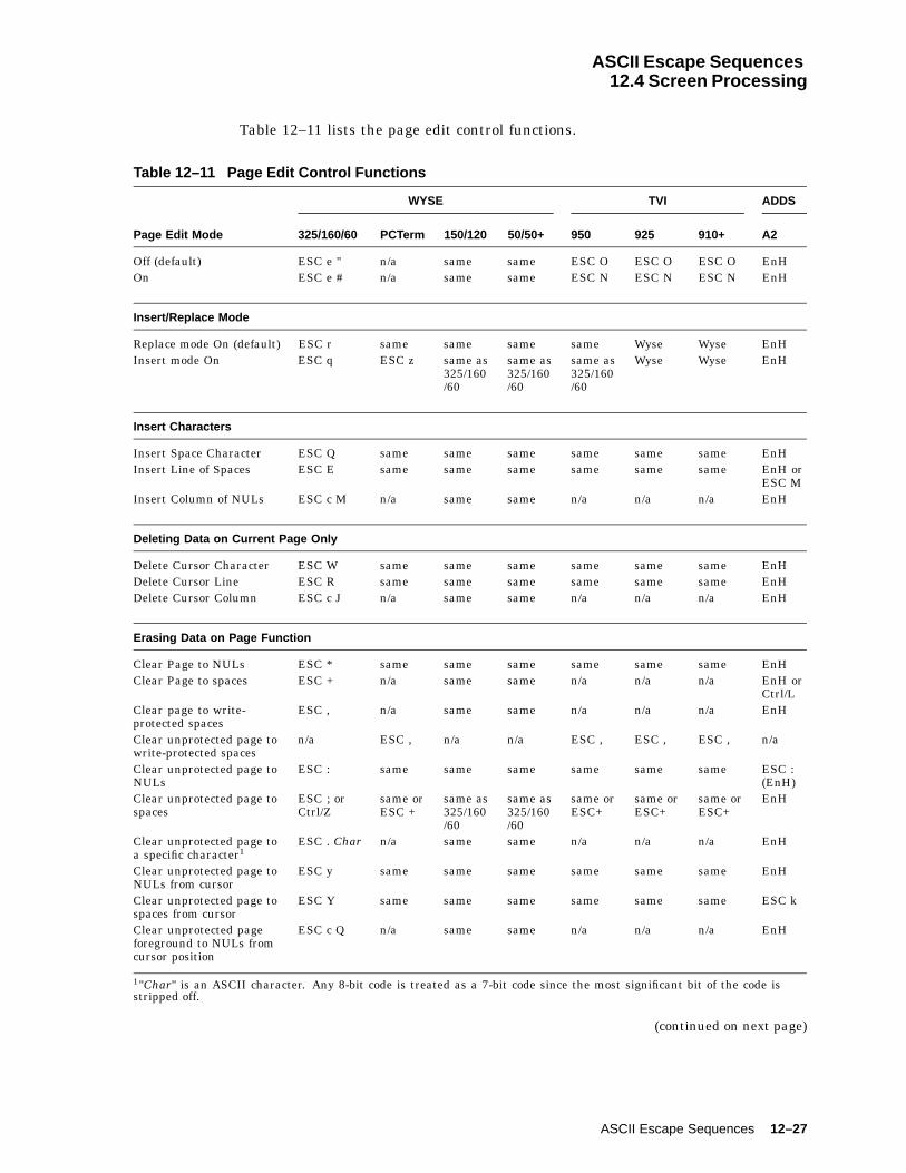
ASCII Escape Sequences12.4 Screen Processing
Table 12–11 lists the page edit control functions.
Table 12–11 Page Edit Control Functions
WYSE TVI ADDS
Page Edit Mode 325/160/60 PCTerm 150/120 50/50+ 950 925 910+ A2
Off (default) ESC e " n/a same same ESC O ESC O ESC O EnHOn ESC e # n/a same same ESC N ESC N ESC N EnH
Insert/Replace Mode
Replace mode On (default) ESC r same same same same Wyse Wyse EnHInsert mode On ESC q ESC z same as
325/160/60
same as325/160/60
same as325/160/60
Wyse Wyse EnH
Insert Characters
Insert Space Character ESC Q same same same same same same EnHInsert Line of Spaces ESC E same same same same same same EnH or
ESC MInsert Column of NULs ESC c M n/a same same n/a n/a n/a EnH
Deleting Data on Current Page Only
Delete Cursor Character ESC W same same same same same same EnHDelete Cursor Line ESC R same same same same same same EnHDelete Cursor Column ESC c J n/a same same n/a n/a n/a EnH
Erasing Data on Page Function
Clear Page to NULs ESC * same same same same same same EnHClear Page to spaces ESC + n/a same same n/a n/a n/a EnH or
Ctrl/LClear page to write-protected spaces
ESC , n/a same same n/a n/a n/a EnH
Clear unprotected page towrite-protected spaces
n/a ESC , n/a n/a ESC , ESC , ESC , n/a
Clear unprotected page toNULs
ESC : same same same same same same ESC :(EnH)
Clear unprotected page tospaces
ESC ; orCtrl/Z
same orESC +
same as325/160/60
same as325/160/60
same orESC+
same orESC+
same orESC+
EnH
Clear unprotected page toa specific character1
ESC . Char n/a same same n/a n/a n/a EnH
Clear unprotected page toNULs from cursor
ESC y same same same same same same EnH
Clear unprotected page tospaces from cursor
ESC Y same same same same same same ESC k
Clear unprotected pageforeground to NULs fromcursor position
ESC c Q n/a same same n/a n/a n/a EnH
1"Char" is an ASCII character. Any 8-bit code is treated as a 7-bit code since the most significant bit of the code isstripped off.
(continued on next page)
ASCII Escape Sequences 12–27

ASCII Escape Sequences12.4 Screen Processing
Table 12–11 (Cont.) Page Edit Control Functions
Erasing Data onWYSE TVI ADDS
Page Function (cont.) 325/160/60 PCTerm 150/120 50/50+ 950 925 910+ A2
Clear unprotected pageforeground to spaces fromcursor position
ESC c P n/a same same n/a n/a n/a EnH
Clear unprotected area toend of line with NULs
ESC c L n/a same same n/a n/a n/a EnH
Clear unprotected area toend of line with spaces
ESC c O n/a same same n/a n/a n/a EnH
Clear unprotected linefrom cursor position toNULs
ESC t same same same same same same EnH
Clear unprotected linefrom cursor position tospaces
ESC T same same same n/a n/a n/a ESC K
Clear unprotected lineforeground from cursorposition to NULs
ESC c S n/a same same n/a n/a n/a EnH
Clear unprotected lineforeground from cursorposition to spaces
ESC c R n/a same same n/a n/a n/a EnH
Clear unprotected positionto NULs
ESC c K n/a same same n/a n/a n/a EnH
Clear unprotected columnto a specific character1
ESC c I Char n/a same same n/a n/a n/a EnH
Clear column to write-protected space
ESC V same same same same same same EnH
1"Char" is an ASCII character. Any 8-bit code is treated as a 7-bit code since the most significant bit of the code isstripped off.
12.4.1 Rectangular Area OperationsUpon execution, a rectangle that is drawn with line drawing characters andnormal attributes is displayed on the screen. If the four lines that form therectangle are occupied with data before the command execution, then the data isreplaced.
The parameters Line, Column, and the line, column number of the cursor decidewhere the rectangle will be located. See Table 12–12.
The parameters Line and Column in format 1 are ASCII characters whosedecimal values are the desired numbers plus 31.
The parameter Column in format 2 is an ASCII character whose decimal value isthe desired column number plus 31 and minus 80.
The symbol "~" in escape sequences indicates number "80" to be added to the"Column" value. The result of executing this command draws a rectangle 80columns wider than the rectangle drawn by the command without the "~" symbol.Therefore, this command is not recommended for 80-column mode.
Char is an ASCII character. If an 8-bit code is entered as a parameter value,then the most significant bit of the code is stripped off.
12–28 ASCII Escape Sequences
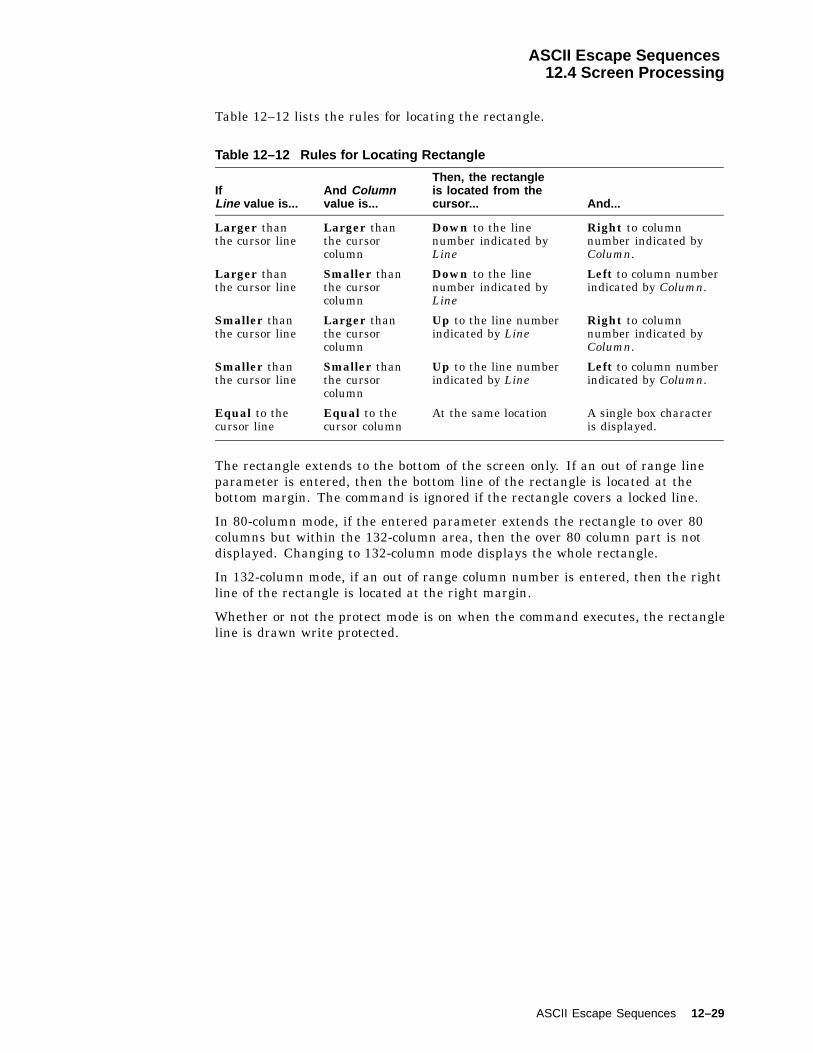
ASCII Escape Sequences12.4 Screen Processing
Table 12–12 lists the rules for locating the rectangle.
Table 12–12 Rules for Locating Rectangle
IfLine value is...
And Columnvalue is...
Then, the rectangleis located from thecursor... And...
Larger thanthe cursor line
Larger thanthe cursorcolumn
Down to the linenumber indicated byLine
Right to columnnumber indicated byColumn.
Larger thanthe cursor line
Smaller thanthe cursorcolumn
Down to the linenumber indicated byLine
Left to column numberindicated by Column.
Smaller thanthe cursor line
Larger thanthe cursorcolumn
Up to the line numberindicated by Line
Right to columnnumber indicated byColumn.
Smaller thanthe cursor line
Smaller thanthe cursorcolumn
Up to the line numberindicated by Line
Left to column numberindicated by Column.
Equal to thecursor line
Equal to thecursor column
At the same location A single box characteris displayed.
The rectangle extends to the bottom of the screen only. If an out of range lineparameter is entered, then the bottom line of the rectangle is located at thebottom margin. The command is ignored if the rectangle covers a locked line.
In 80-column mode, if the entered parameter extends the rectangle to over 80columns but within the 132-column area, then the over 80 column part is notdisplayed. Changing to 132-column mode displays the whole rectangle.
In 132-column mode, if an out of range column number is entered, then the rightline of the rectangle is located at the right margin.
Whether or not the protect mode is on when the command executes, the rectangleline is drawn write protected.
ASCII Escape Sequences 12–29

ASCII Escape Sequences12.4 Screen Processing
Table 12–13 lists the rectangle area control functions. The word ‘‘same’’ signifiesthe same control sequences as in the WYSE 325/160/60 column.
Table 12–13 Rectangle Area Control Functions
Draw Rectangle in 80/132WYSE TVI ADDS
column Current Page 325/160/60 PCTerm 150/120 50/50+ 950 925 910+ A2
Format 1 ESC c G Line Coln/a same same n/a n/a n/a EnH
Format 21 ESC c G Line ~ Coln/a same same n/a n/a n/a EnH
Fill Rectangle with a Specific Character in 80/132-column Cursor Page
Format 1 ESC c H Line Col Charn/a same same n/a n/a n/a EnH
Format 21 ESC c H Line ~ Col Charn/a same same n/a n/a n/a EnH
Fill unprotected Rectangle with a specific character
Format 1 ESC c F Line Col Charn/a same same n/a n/a n/a EnH
Format 21 ESC c F Line ~ Col Charn/a same same n/a n/a n/a EnH
Draw Rectangle 2
Draw rectangle area to ESC c N Width Heightright and below cursor. n/a same same n/a n/a n/a EnH
Swap/Copy/Move 3 WYSE 325/160/60
Swap, copy, or move thedata in a rectangle toanother rectangle.
ESC c ^ Action S_page P S_n1 R S_n2 C S_n3 R S_n4 C D_page P D_n1 R D_n2 C
Parameters: Action Description0 Swaps data between the source and the destination rectangles.1 Copies the content of the source rectangle to a destination rectangle,
preserving the contents of the source rectangle.2 Moves the contents of the source rectangle to destination rectangle, clearing
the source rectangle.
Parameter DescriptionS_page Page number of the source rectangleS_n1 Starting line number of the source rectangle (top left corner)S_n2 Starting column number of the source rectangle (top left corner)S_n3 Ending line number of the source rectangle (bottom right corner)S_n4 Ending column number of the source rectangle (bottom right corner)D_page Page number of the destination rectangle
1Not recommended for 80-column mode.2Parameters Line and Column are ASCII characters whose decimal values are the desired numbers plus 31. SeeSection 12.4.1.1.3See Section 12.4.1.2.
(continued on next page)
12–30 ASCII Escape Sequences
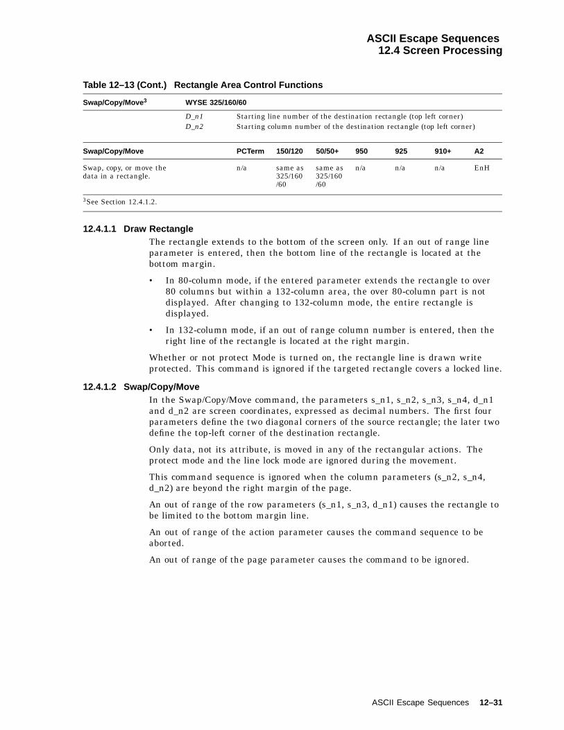
ASCII Escape Sequences12.4 Screen Processing
Table 12–13 (Cont.) Rectangle Area Control Functions
Swap/Copy/Move 3 WYSE 325/160/60
D_n1 Starting line number of the destination rectangle (top left corner)D_n2 Starting column number of the destination rectangle (top left corner)
Swap/Copy/Move PCTerm 150/120 50/50+ 950 925 910+ A2
Swap, copy, or move thedata in a rectangle.
n/a same as325/160/60
same as325/160/60
n/a n/a n/a EnH
3See Section 12.4.1.2.
12.4.1.1 Draw RectangleThe rectangle extends to the bottom of the screen only. If an out of range lineparameter is entered, then the bottom line of the rectangle is located at thebottom margin.
• In 80-column mode, if the entered parameter extends the rectangle to over80 columns but within a 132-column area, the over 80-column part is notdisplayed. After changing to 132-column mode, the entire rectangle isdisplayed.
• In 132-column mode, if an out of range column number is entered, then theright line of the rectangle is located at the right margin.
Whether or not protect Mode is turned on, the rectangle line is drawn writeprotected. This command is ignored if the targeted rectangle covers a locked line.
12.4.1.2 Swap/Copy/MoveIn the Swap/Copy/Move command, the parameters s_n1, s_n2, s_n3, s_n4, d_n1and d_n2 are screen coordinates, expressed as decimal numbers. The first fourparameters define the two diagonal corners of the source rectangle; the later twodefine the top-left corner of the destination rectangle.
Only data, not its attribute, is moved in any of the rectangular actions. Theprotect mode and the line lock mode are ignored during the movement.
This command sequence is ignored when the column parameters (s_n2, s_n4,d_n2) are beyond the right margin of the page.
An out of range of the row parameters (s_n1, s_n3, d_n1) causes the rectangle tobe limited to the bottom margin line.
An out of range of the action parameter causes the command sequence to beaborted.
An out of range of the page parameter causes the command to be ignored.
ASCII Escape Sequences 12–31

ASCII Escape Sequences12.5 Printing/Sending Data
12.5 Printing/Sending DataThis section describes commands to print and send data.
12.5.1 Sending DataThis section describes commands to send a defined area of data on the screenthrough the main communication port (Comm1) using ASCII control functions.Individual commands address the specific data to be sent.
In send operations, delimiter characters are sent along with data to mark a lineend, transfer complete, or the protect data and its area. Table 12–14 lists thepossible delimiter types. Depending on the scope of data (line, page) and the typeof data (protected, unprotected) that has been sent, different delimiter charactersare enclosed. The individual commands explain which delimiter should be sentwith each command.
Table 12–14 lists the types of delimiters to send data.
Table 12–14 Send Data Delimiters
Delimiter Type Sent . . .
End of the line At the end of each line but not at the end of the page (block).
Transfer complete After each Send Data action, except for a "Send the CursorCharacter" command.
Field separator To take the position of the protected field data when "SendUnprotected" command is executed and Protect mode is on.
Start protect field andEnd protect field
To mark the beginning and the ending of a write-protected fieldof data when Protect mode is on.
All the send data actions in this section, except "Send the Cursor Character"command, use the following rules:
• The attributes are not sent along with their data. But a Space character (Hex20) is inserted between two distinct attribute data to indicate the attributedifference.
• During the process of sending characters, the cursor moves to the location ofthe character being sent.
• Protect mode on: The cursor does not move.
• Protect mode off: The cursor moves to the left margin of the next line.
• Null characters on the screen are not sent.
• Delimiter characters:
• TVI modes and WYSE 325/160/60 PCTerm modes: Defined bycommand "Define Delimiters" (Refer to the command for details.)
• Other personalities: See Table 12–15.
12–32 ASCII Escape Sequences
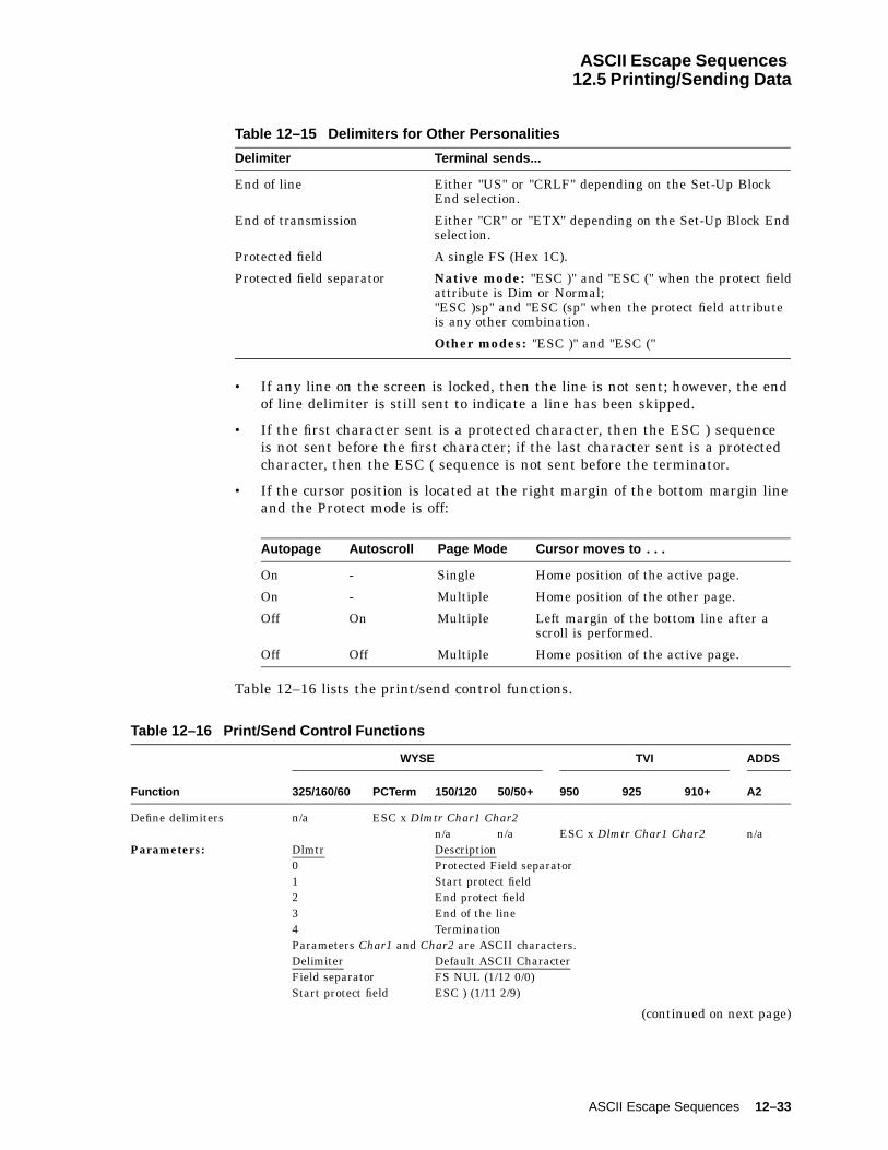
ASCII Escape Sequences12.5 Printing/Sending Data
Table 12–15 Delimiters for Other Personalities
Delimiter Terminal sends...
End of line Either "US" or "CRLF" depending on the Set-Up BlockEnd selection.
End of transmission Either "CR" or "ETX" depending on the Set-Up Block Endselection.
Protected field A single FS (Hex 1C).
Protected field separator Native mode: "ESC )" and "ESC (" when the protect fieldattribute is Dim or Normal;"ESC )sp" and "ESC (sp" when the protect field attributeis any other combination.
Other modes: "ESC )" and "ESC ("
• If any line on the screen is locked, then the line is not sent; however, the endof line delimiter is still sent to indicate a line has been skipped.
• If the first character sent is a protected character, then the ESC ) sequenceis not sent before the first character; if the last character sent is a protectedcharacter, then the ESC ( sequence is not sent before the terminator.
• If the cursor position is located at the right margin of the bottom margin lineand the Protect mode is off:
Autopage Autoscroll Page Mode Cursor moves to . . .
On - Single Home position of the active page.
On - Multiple Home position of the other page.
Off On Multiple Left margin of the bottom line after ascroll is performed.
Off Off Multiple Home position of the active page.
Table 12–16 lists the print/send control functions.
Table 12–16 Print/Send Control Functions
WYSE TVI ADDS
Function 325/160/60 PCTerm 150/120 50/50+ 950 925 910+ A2
Define delimiters n/a ESC x Dlmtr Char1 Char2n/a n/a ESC x Dlmtr Char1 Char2 n/a
Parameters: Dlmtr Description0 Protected Field separator1 Start protect field2 End protect field3 End of the line4 TerminationParameters Char1 and Char2 are ASCII characters.Delimiter Default ASCII CharacterField separator FS NUL (1/12 0/0)Start protect field ESC ) (1/11 2/9)
(continued on next page)
ASCII Escape Sequences 12–33
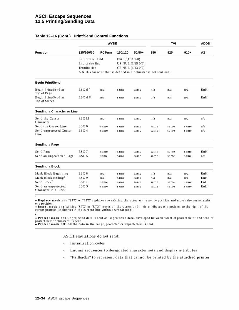
ASCII Escape Sequences12.5 Printing/Sending Data
Table 12–16 (Cont.) Print/Send Control Functions
WYSE TVI ADDS
Function 325/160/60 PCTerm 150/120 50/50+ 950 925 910+ A2
End protect field ESC ( (1/11 2/8)End of the line US NUL (1/15 0/0)Termination CR NUL (1/13 0/0)A NUL character that is defined in a delimiter is not sent out.
Begin Print/Send
Begin Print/Send atTop of Page
ESC d ` n/a same same n/a n/a n/a EnH
Begin Print/Send atTop of Screen
ESC d & n/a same same n/a n/a n/a EnH
Sending a Character or Line
Send the CursorCharacter
ESC M n/a same same n/a n/a n/a n/a
Send the Cursor Line ESC 6 same same same same same same n/aSend unprotected CursorLine
ESC 4 same same same same same same n/a
Sending a Page
Send Page ESC 7 same same same same same same EnHSend an unprotected Page ESC 5 same same same same same same n/a
Sending a Block
Mark Block Beginning ESC 8 n/a same same n/a n/a n/a EnHMark Block Ending1 ESC 9 n/a same same n/a n/a n/a EnHSend Block2 ESC s same same same same same same EnHSend an unprotectedCharacter in a Block
ESC S same same same same same same EnH
1
� Replace mode on: "STX" or "ETX" replaces the existing character at the active position and moves the cursor rightone position.� Insert mode on: Writing "STX" or "ETX" moves all characters and their attributes one position to the right of thecursor position (inclusive) in the current line without wraparound.2
� Protect mode on: Unprotected data is sent as is; protected data, enveloped between "start of protect field" and "end ofprotect field" delimiters, is sent.� Protect mode off: All the data in the range, protected or unprotected, is sent.
ASCII emulations do not send:
• Initialization codes
• Ending sequences to designated character sets and display attributes
• "Fallbacks" to represent data that cannot be printed by the attached printer
12–34 ASCII Escape Sequences

ASCII Escape Sequences12.5 Printing/Sending Data
The only factors that affect printing data are data and parity settings.
Data/Parity Setting Characters are printed . . .
8-bit As is
7-bit After stripping off the most significant bit
Table 12–17 lists the printing data control functions.
Table 12–17 Printing Data Control Functions
WYSE TVI ADDS
Autoprint Mode 1 325/160/60 PCTerm 150/120 50/50+ 950 925 910+ A2
Off (default) Ctrl/T ESC A Ctrl/T Ctrl/T ESC A or Ctrl/T Ctrl/TOn Ctrl/R ESC @ Ctrl/R Ctrl/R ESC @ or Ctrl/R Ctrl/R
Control Print Mode 3
Off Ctrl/T ESC a Ctrl/T Ctrl/T ESC a ESC a ESC a ESC 4On ESC d # or
Ctrl/X 2ESC ´ same as
325/160/60
same as325/160/60
ESC ` ESC ` ESC ` ESC 3ESC d#(EnH)
Aux Receive Mode
Off (default) ESC d Sp n/a same same n/a n/a n/a EnHOn ESC d ! n/a same same n/a n/a n/a EnH
Bidirectional Mode 4
Off (default) ESC d $ Ctrl/T same as325/160/60
same as325/160/60
Ctrl/T Ctrl/T Ctrl/T EnH
On ESC d % Ctrl/R same as325/160/60
same as325/160/60
Ctrl/R Ctrl/R Ctrl/R EnH
Print Page to the Cursor Position
Formatted Page5 ESC P same same same same same Wyse EnHFormatted Page(unprotected)
ESC @ n/a same same n/a n/a n/a EnH
Unformatted Page5 ESC p orESC L
n/a same same ESC L n/a n/a ESC p
1 The symbol ">" is displayed in the status line when in Autoprint mode.2Enhanced mode is off.3The symbol "=" is displayed in the status line when in Autoprint mode.4 Turning off Bidirectional mode turns off Aux Receive mode and forces a normal print mode.5 The time prints out in a format such as "TIME AM/PM 00:00." At the end of the time message, the following is sent tothe printer port: NUL Ctrl/F NULThe page prints as formatted data. The terminal sends an "ACK" to the host at the end of a print operation if ACK modeis on.
(continued on next page)
ASCII Escape Sequences 12–35

ASCII Escape Sequences12.5 Printing/Sending Data
Table 12–17 (Cont.) Printing Data Control Functions
Print the PageWYSE TVI ADDS
with Time Message 5 325/160/60 PCTerm 150/120 50/50+ 950 925 910+ A2
n/a ESC L n/a n/a n/a ESC L ESC L n/a
Pass a Character to the Printer Port
Ctrl/P Char Wyse same same Wyse Wyse Wyse n/a
Define the Page Print Terminator
n/a ESC p Ps Charn/a n/a ESC p Char n/a
5 The time prints out in a format such as "TIME AM/PM 00:00." At the end of the time message, the following is sent tothe printer port: NUL Ctrl/F NULThe page prints as formatted data. The terminal sends an "ACK" to the host at the end of a print operation if ACK modeis on.
12.5.2 Graphics CharactersTable 12–18 lists the graphic characters.
Table 12–18 Graphic Characters
WYSE TVI ADDS
Graphics Mode 325/160/60 PCTerm 150/120 50/50+ 950 925 910+ A2
On ESC H orCtrl/B
ESC $ same as325/160/60
same as325/160/60
ESC $or Wyse
ESC $or Wyse
ESC $or Wyse
EnH
Off (default) ESC H orCtrl/C
ESC % same as325/160/60
same as325/160/60
ESC %or Wyse
ESC %or Wyse
ESC %or Wyse
EnH
Display Graphic Character
Display character fromthe first 32 character set.1
ESC H Char n/a same same n/a n/a n/a EnH
1The parameter Char is an ASCII character in the range of Hex 20 to Hex 7E.
With Graphics mode on, all received codes in the range of 00 to 7E are displayedas characters in the range of Hex 00 to Hex 1F in the same character set.
This is done by stripping off the highest 3 bits of the code. For example:
Receiving . . . Displays . . .
21, 41, or 61 (Hex) 01 (Hex) character
2C, 4C, or 6C (Hex) 0C (Hex) character
31, 51, or 71 (Hex) 11 (Hex) character
12–36 ASCII Escape Sequences
ASCII Escape Sequences12.5 Printing/Sending Data
Most character sets in ASCII emulation contain characters in the range of Hex00 and Hex 1F. For example, the Native character set contains 16 line-drawinggraphics characters from Hex 10 to Hex 1F and 16 CRM characters from Hex 00to 0F. But in most of the cases, Hex codes 00 to 1F are treated as control codes.To display these graphic characters, Graphic mode has to be turned on.
When the Graphic mode is on, new characters entered have normal attributesregardless of the state of the Write-Protect mode attribute. With Protect mode on,all the entered characters, except CRM characters, are protected.
To design a character font, see Chapter 13.
ASCII Escape Sequences 12–37


13Defining and Loading ASCII Character Fonts
This chapter defines the ASCII character fonts and describes how to load thefonts.
13.1 Character SetsIn WYSE mode and ADDS Enhanced mode, desired characters can be acquiredby loading them from various built-in character sets or by designing them using apixel pattern�.
13.1.1 PCTerm on US KeyboardThe default and only character set supported for PCTerm on the US Keyboard isthe PC International character set. This is a 256-character set, of which the first128 characters form the PC Standard character set�.
13.1.2 WYSE and ADDS Enhanced PersonalitiesWYSE mode and ADDS enhanced mode support ten built-in ROM character setsand four font banks, which are physical locations in memory. Each character sethas 128 characters (Hex 00 to Hex 7F), thus each font bank has the same spaceallocation.
The character set must be loaded into a font bank to become an "active" characterset. Characters cannot be displayed directly by calling their physical locations;they can only be displayed through a series of steps to make them active. First,the primary and secondary logical character sets are defined by pointing to thedesired font banks. Then, the active character set is defined for the terminal todisplay and receive codes. See Table 13–1 on how to display and load charactersets.
Table 13–1 Display and Load Character Sets
Step Description
1. Load font bank withbuilt-in character set
Load a target character set from one of the tenbuilt-in character sets into a font bank.
or Define and load character Design a character and load it into a font bank.
2. Define logical character set Define primary or secondary character set topoint to the font bank.
3. Select active character set Set active character set to point to either aprimary or a secondary character set.
Notes
WYSE 160: You can display all 512 characters in the four font banks onthe screen at the same time.
� Refer to the IBM Code Page 437.
Defining and Loading ASCII Character Fonts 13–1

Defining and Loading ASCII Character Fonts13.1 Character Sets
WYSE 50+: You can only display one font bank on the screen at a time.
Figure 13–1 shows the process for selecting character sets.
Figure 13–1 Process of Selecting Character Sets
NativeStandard ASCIIPC StandardUS ANSIISO Latin 1 Supp
PC MultinationalGraphic 1Graphic 2Graphic 3ANSI Supp
Define and
Font Bank 0 Font Bank 1 Font Bank 2 Font Bank 3
PrimaryCharacter Set
SecondaryCharacter Set
Active
Character Set
LoadCharacter
Communication Line Code
Select Primary
Select Secondary
Built−In ROM Character Sets User Input
(128 Characters) (128 Characters)
(128 Characters)
(128 Fonts) (128 Fonts) (128 Fonts) (128 Fonts)
0 1 0 1 0 1 0 1
0 1 0 1
2 3 4 5 2 3 4 5 2 3 4 5
2 3 4 5 2 3 4 5
2 3 4 5 6 76 7 6 7 6 7
6 76 7
5 6 70 1 2 3 4
MA−0027−93.GRA
1. Load
2. Define
3. Select
The VT520 selects a character set from one of the built-in character sets by thefollowing process. Refer to Table 13–1 for details.
1. Load the character sets into the font banks.
2. Define the primary and secondary character set from the font buffers.
3. Select which character set will be the active characters set.
13–2 Defining and Loading ASCII Character Fonts
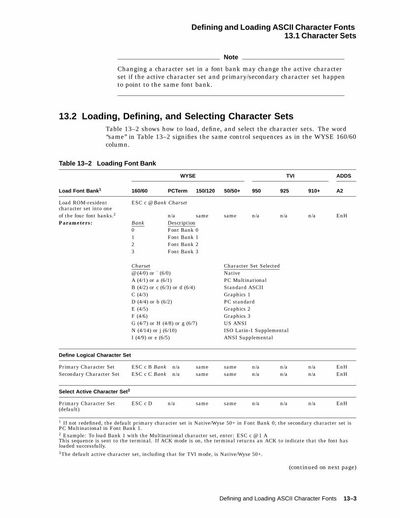
Defining and Loading ASCII Character Fonts13.1 Character Sets
Note
Changing a character set in a font bank may change the active characterset if the active character set and primary/secondary character set happento point to the same font bank.
13.2 Loading, Defining, and Selecting Character SetsTable 13–2 shows how to load, define, and select the character sets. The word‘‘same’’ in Table 13–2 signifies the same control sequences as in the WYSE 160/60column.
Table 13–2 Loading Font Bank
WYSE TVI ADDS
Load Font Bank 1 160/60 PCTerm 150/120 50/50+ 950 925 910+ A2
Load ROM-residentcharacter set into one
ESC c @ Bank Charset
of the four font banks.2 n/a same same n/a n/a n/a EnHParameters: Bank Description
0 Font Bank 01 Font Bank 12 Font Bank 23 Font Bank 3
Charset Character Set Selected@ (4/0) or ` (6/0) NativeA (4/1) or a (6/1) PC MultinationalB (4/2) or c (6/3) or d (6/4) Standard ASCIIC (4/3) Graphics 1D (4/4) or b (6/2) PC standardE (4/5) Graphics 2F (4/6) Graphics 3G (4/7) or H (4/8) or g (6/7) US ANSIN (4/14) or j (6/10) ISO Latin-1 SupplementalI (4/9) or e (6/5) ANSI Supplemental
Define Logical Character Set
Primary Character Set ESC c B Bank n/a same same n/a n/a n/a EnHSecondary Character Set ESC c C Bank n/a same same n/a n/a n/a EnH
Select Active Character Set 3
Primary Character Set(default)
ESC c D n/a same same n/a n/a n/a EnH
1 If not redefined, the default primary character set is Native/Wyse 50+ in Font Bank 0; the secondary character set isPC Multinational in Font Bank 1.2 Example: To load Bank 1 with the Multinational character set, enter: ESC c @ 1 AThis sequence is sent to the terminal. If ACK mode is on, the terminal returns an ACK to indicate that the font hasloaded successfully.3The default active character set, including that for TVI mode, is Native/Wyse 50+.
(continued on next page)
Defining and Loading ASCII Character Fonts 13–3

Defining and Loading ASCII Character Fonts13.2 Loading, Defining, and Selecting Character Sets
Table 13–2 (Cont.) Loading Font Bank
Select Active Character Set 3
Secondary Character Set ESC c E n/a same same4 n/a n/a n/a EnH
Automatic Font Loading
On (default) ESC e O n/a same same n/a n/a n/a n/aOff ESC e N n/a same same n/a n/a n/a n/a
WYSE TVI ADDS
Clear Font Bank 160/60 PCTerm 150/120 50/50+ 950 925 910+ A2
Erase a character setfrom one of the four fontbanks.1
ESC c ? Bank n/a same same n/a n/a n/a EnH
1 If not redefined, the default primary character set is Native/Wyse 50+ in Font Bank 0; the secondary character set isPC Multinational in Font Bank 1.3The default active character set, including that for TVI mode, is Native/Wyse 50+.4See Note on the following page.
Note
Wyse 50+ Mode: Because Wyse 50+ can only display one font bank atany given time, executing the sequence has a side effect of convertingthe existing screen characters into new characters that have equivalentpositions as the old characters in the original character sets.
For example, a screen full of "!" characters are displayed when theactive character set is Native/Wyse 50+. Executing Select SecondaryCharacter Set to select the PC Multinational as the active characterset causes the "!" on the screen to be converted to "í ". The character "!"occupies Hex 21 in Native/Wyse 50+ character set; whereas, "í " occupiesHex 21 in the PC Multinational character set.
13–4 Defining and Loading ASCII Character Fonts

Defining and Loading ASCII Character Fonts13.3 Designing a Character Font
13.3 Designing a Character FontTable 13–3 shows how to design a character font.
Table 13–3 Design a Character Font
Define andWYSE TVI ADDS
Load a Character 160/60 PCTerm 150/120 50/50+ 950 925 910+ A2
Design a character font ESC c A Bank Pp bb..bb Ctrl/Yn/a same same n/a n/a n/a EnH
The sequence in Table 13–3 defines the bb..bb string and loads it in the Ppposition of the Bank font bank.
Bank is the font bank that holds a defined character set. Refer to Table 13–2.
Pp is a 2-byte Hex code in the range of 00 to 7F specifying a position in thatfont bank.
bb...bb is a Hex code string defining the bit pattern of the defined character.The string contains one of the following:
� 16 2-byte Hex codes for a 10 � 16 cell size character
� 13 2-byte Hex codes for a 10 � 13 cell size character
� 10 2-byte Hex codes for a 10 � 10 cell size character
The command aborts if Ctrl/Y in the sequence is received before the expectednumber of Hex codes in bb...bb is received.
Perform the following steps to draw a graphic character in a 10 � 16 cell:
1. Divide the cell into 10 � 16 pixels and draw the desired font pattern.Observe the following rules:
a. Start the pattern from the left column in the cell.
b. For an alphanumeric character, the pattern should occupy only the leftseven columns; for other graphic characters, the pattern can extend to theeighth column. (The ninth and tenth column follow whatever you place inthe eighth column.)
c. If possible, leave some space at both the top and bottom pixels to allow forspacing.
2. Turn the font pattern into a value represented as 1s and 0s; where "1"represents a filled pixel, and "0" represents an empty pixel.
3. Encode the bit pattern, 4 bits (a nibble) at a time, row by row, intohexadecimal numbers 0 to F. (Do not encode the right two columns.)
4. Form the two nibbles per row into a 2-byte Hex code.
5. Feed the 16 Hex codes into the bb...bb string. See the following example.
Defining and Loading ASCII Character Fonts 13–5
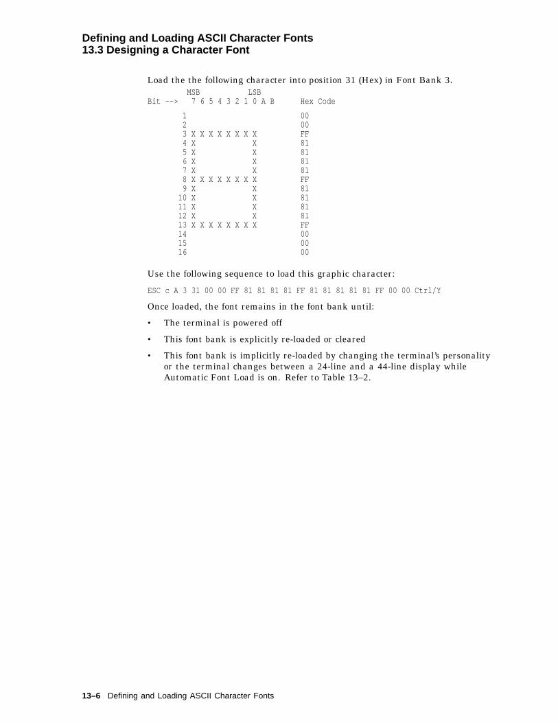
Defining and Loading ASCII Character Fonts13.3 Designing a Character Font
Load the the following character into position 31 (Hex) in Font Bank 3.MSB LSB
Bit --> 7 6 5 4 3 2 1 0 A B Hex Code
1 002 003 X X X X X X X X FF4 X X 815 X X 816 X X 817 X X 818 X X X X X X X X FF9 X X 81
10 X X 8111 X X 8112 X X 8113 X X X X X X X X FF14 0015 0016 00
Use the following sequence to load this graphic character:
ESC c A 3 31 00 00 FF 81 81 81 81 FF 81 81 81 81 81 FF 00 00 Ctrl/Y
Once loaded, the font remains in the font bank until:
• The terminal is powered off
• This font bank is explicitly re-loaded or cleared
• This font bank is implicitly re-loaded by changing the terminal’s personalityor the terminal changes between a 24-line and a 44-line display whileAutomatic Font Load is on. Refer to Table 13–2.
13–6 Defining and Loading ASCII Character Fonts
AVT Keyboard Legend Data
This appendix describes the Compose processing, non-spacing diacritical marks,and keyboard layouts for the VT keyboard layouts.
A.1 Compose Processing and Non-spacing Diacritical MarksOf the new keyboard dialects added to the VT520, only Hebrew and SCS allowsthree-stroke compose sequences. Pressing "Hebrew" (the Compose key) initiates acompose sequence. Ctrl/Hebrew is used to switch between Group 1 and Group 2.
The other new keyboard dialects employ a Group Shift mechanism to accessadditional characters so there is no Compose key and no three-stroke composesequences. Three keyboards have non-spacing diacritical marks in Group 1 orGroup 2. These keystrokes initiate a two-stroke "auto-compose" sequence.
Table A–1 lists the VT keyboard non-spacing diacritical marks. The brackets inTable A–1 are not part of the non-spacing diacritical marks.
Table A–1 VT Keyboard Non-Spacing Diacritical Marks
VT Keyboard 1 Acute Caron Circumflex Dieresis Ring Tonos
Czech VT [´] [_] [^]2 [¨] [°]3
Greek VT [¨]4 [!]4
Slovak VT [´] [_] [^]2 [¨] [°]3
1Hebrew, Hungarian, Polish, Romanian, Russian, SCS, Turkish-Q and Turkish-F keyboards have nonon-spacing diacritical marks.2Circumflex over O/o can be produced with caron and O/o.3Ring over U/u can also be produced with caron and U/u.4Greek iota with diaeresis and accent can be produced by pressing diaeresis, accent, then iota. Greekupsilon with diaeresis and accent can be produced by pressing diaeresis, accent, then upsilon.
A.2 VT KeyboardsThe VT keyboard layouts are shown in the figures that follow:
Note
The keyboards shipped with the product may not look exactly like thoseillustrated here. Different fonts may be used, and some characters maynot look the same.
VT Keyboard Legend Data A–1
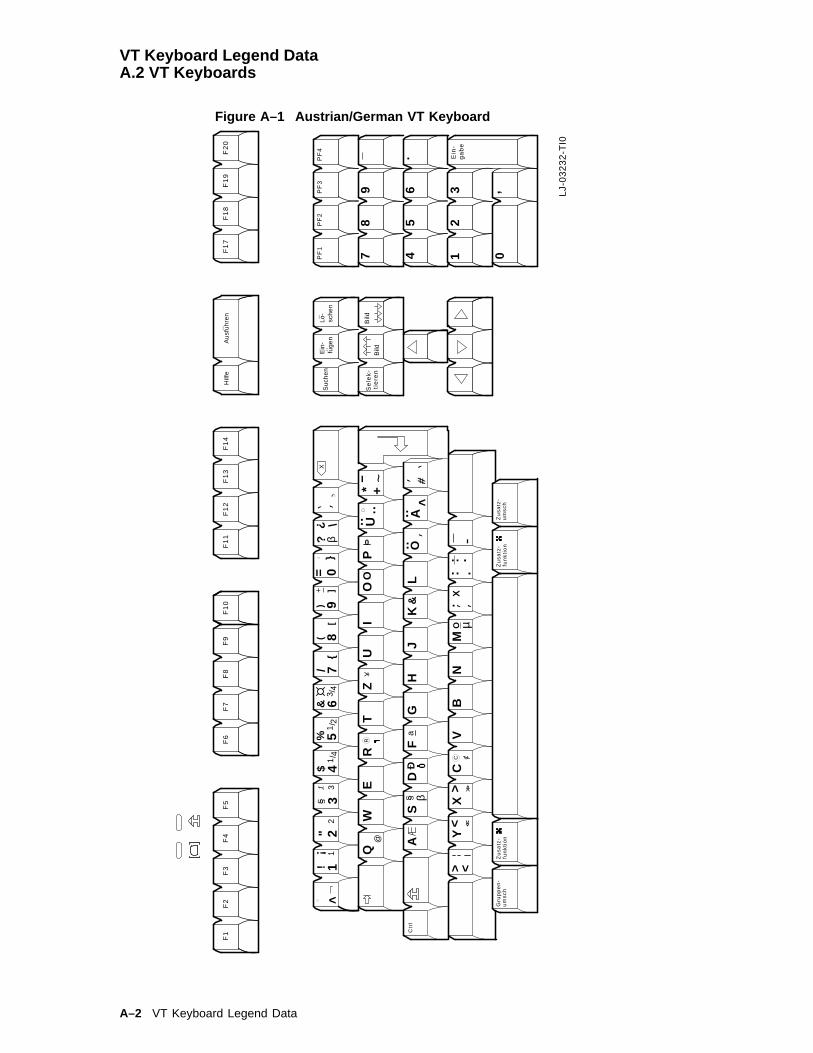
VT Keyboard Legend DataA.2 VT Keyboards
Figure A–1 Austrian/German VT Keyboard
LJ-
03
23
2-T
I0
F1
F2
F3
F5
78
9
45
6 32
1 0
YX
CV
BN
AS
DF
GH
JK
L
IO
PT
ZU
WE
RQ
> <
F4
F6
F7
F8
F1
0F
9F
11
F1
2F
13
F1
4F
17
F1
8F
19
F2
0
PF
1P
F2
PF
3P
F4
_
X
Ctr
l
Hilf
eA
usf
uh
ren
_
Bild
BildLo
-sc
he
nE
in-
fug
en
Su
che
n
Se
lek
-
Ein
-
12
34
56
78
90
!
#
$%
&
*
()
Gru
pp
en
-
?
.:
\
}]
-
+
=
}]
S
S
..
O..
..
..
\
<
.
β
ga
be
tie
ren
..
um
sc
h
A
U?
+ _
4/32/
14/
13
21
@
RY
O
Zu
sa
tz-
fun
kti
on
D 0
SS β
a&
>0
=
: .X
O
~
<>
<<
<<
C CM
Zu
sa
tz-
fun
kti
on
Zu
sa
tz-
um
sc
h,
..
.
..
"
µ
A–2 VT Keyboard Legend Data
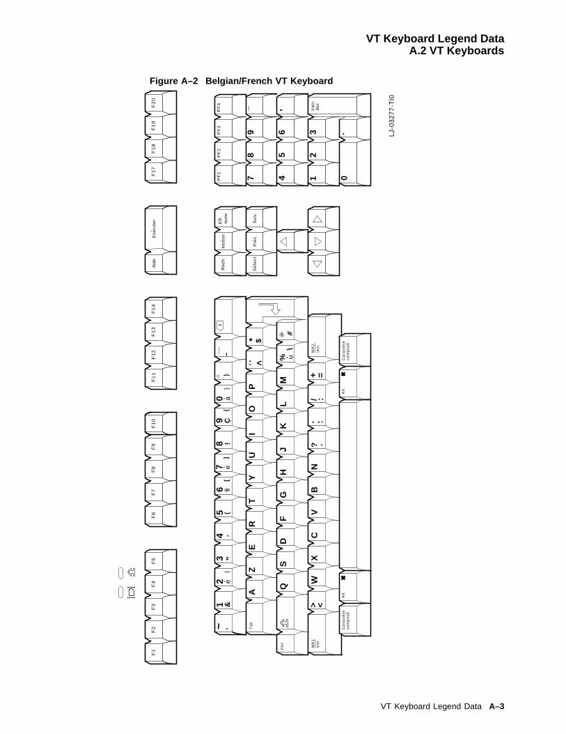
VT Keyboard Legend DataA.2 VT Keyboards
Figure A–2 Belgian/French VT Keyboard
F1
F2
F3
F5
78
9
45
6 32
1 0
WX
CV
BN
QS
DF
GH
JK
L
IO
PT
YU
ZE
R
M
A
> <
F4
F6
F7
F8
F1
0F
9F
11
F1
2F
13
F1
4F
17
F1
8F
19
F2
0
PF
1P
F2
PF
3P
F4 _ ,
X
Alt
Alt
Ta
b
Ctr
l
Pre
c.S
uiv
.
Eff
.te
xte
Inse
rer
Re
ch.
Se
lec
t
Va
li-
de
rM
AJ
.m
in.
Ca
rac
tere
co
mp
os
e
Aid
eE
xecu
ter
MA
J.
min
.
Ca
rac
tere
co
mp
os
e
12
34
56
78
90
!
#
$
%
&
*
()
a
~
?/
.:
\
]-
+ =
]
.
ee
:<
u
S
S
a{{
{. LJ-
03
27
7-T
I0
"C
VT Keyboard Legend Data A–3
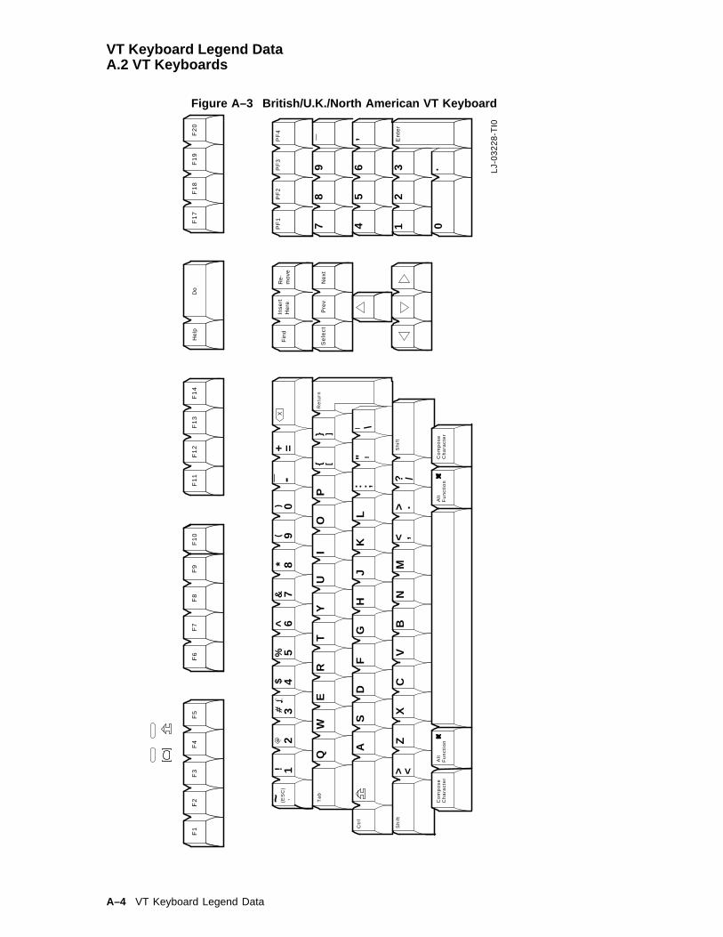
VT Keyboard Legend DataA.2 VT Keyboards
Figure A–3 British/U.K./North American VT Keyboard
F1
F2
F3
F5
78
9
45
6 32
1 0
LJ-
03
22
8-T
I0
12
34
56
78
90
ZX
CV
BN
AS
DF
GH
JK
L
IO
PT
YU
WE
R
M
Q
> <
F4
F6
F7
F8
F1
0F
9F
11
F1
2F
13
F1
4F
17
F1
8F
19
F2
0
PF
1P
F2
PF
3P
F4
En
ter
_ ,
He
lpD
o
X!
#$
%^
&*
()
a+ =
(ES
C)
_ -
Re
turn
Sh
ift
? /.
,
: ;"
\
} ]
} ]
Alt
Fu
nc
tio
nC
om
po
se
Ch
ara
cte
r
><
Alt
Fu
nc
tio
nC
om
po
se
Ch
ara
cte
r
Ta
b
Ctr
l
Sh
ift
Pre
vN
ext
Re-
mo
veIn
sert
He
reF
ind
Se
lec
t
~
.
A–4 VT Keyboard Legend Data

VT Keyboard Legend DataA.2 VT Keyboards
Figure A–4 Canadian-French VT Keyboard
F1
F2
F3
F5
78
9
45
6 32
1 0
LJ-
03
23
0-T
I0
12
34
56
78
90
ZX
CV
BN
AS
DF
GH
JK
L
IO
PT
YU
WE
R
M
Q
> <
F4
F6
F7
F8
F1
0F
9F
11
F1
2F
13
F1
4F
17
F1
8F
19
F2
0
PF
1P
F2
PF
3P
F4 _ ,
X$
%&
*(
)+ =
: ;\
Alt
Fu
nc
tio
nA
ltF
un
cti
on
Ta
b
Ctr
l
Pre
c.S
uiv
.
Eff
.te
xte
Inse
rer
Re
ch.
Se
l.
Va
li-
!
#a
~?
/
.d
er
<
MA
J.
min
.,
E.
-
Ca
rac
tere
co
mp
os
e
Aid
eE
xecu
ter
]]
C
MA
J.
min
.
Ca
rac
tere
co
mp
os
e.
"
VT Keyboard Legend Data A–5

VT Keyboard Legend DataA.2 VT Keyboards
Figure A–5 Czech VT Keyboard
3
45
6
78
9
..
21 0PF
1PF
2PF
3PF
4
Enter− ,
DoHe
lpF1
7F1
9F2
0F1
8
Retu
rn
Shift
1
Alt
Func
tion
Shift
Ctrl
Tab
Com
pose
Char
acte
rAl
tFu
nctio
nCo
mpo
seCh
arac
ter
F11
F12
F13
F14
F2F3
F4F1
F5F6
F7F8
F9F1
0
12
34
56
78
0+
@#
$%
^&
*{
}% =
9~
QW
ER
TU
IO
PZ
/[
( )]
AS
DF
GH
JK
L§
";
!..
XC
VB
NM
Y_
? ,>
<: .
−\|
es
cr
yz
’a’
e’
u’
u
Rem
ove
Selec
tPr
evNe
xt
Find
Inse
rtHe
re´
MA−
0326
−93.
GRA
A–6 VT Keyboard Legend Data

VT Keyboard Legend DataA.2 VT Keyboards
Figure A–6 Danish VT Keyboard
F1
F2
F3
F5
78
9
45
6 32
1 0
12
34
56
78
90
ZX
CV
BN
AS
DF
GH
JK
L
IO
PT
YU
WE
R
M
Q
> <
F4
F6
F7
F8
F1
0F
9F
11
F1
2F
13
F1
4F
17
F1
8F
19
F2
0
PF
1P
F2
PF
3P
F4
_ ,
X!
$%
&(
)
Alt
Hj
lpU
df
r
Fo
rrig
eN
s
te
Sle
tIn
ds
t
S
g
Ind
-
#
*
a
~
Ko
de
Sk
ift
?/
.,
:;
\
}
-+=
}]
S
S
]A
<
O
O
I
s
O
V
lg
Ko
mb
ine
rte
gn
Sk
ift
Ko
mb
ine
rte
gn
Alt
. LJ-
03
27
8-T
I0
"
"
VT Keyboard Legend Data A–7

VT Keyboard Legend DataA.2 VT Keyboards
Figure A–7 Dutch VT Keyboard
F1
F2
F3
F5
78
9
45
6 32
1 0
LJ-
03
22
9-T
I0
12
34
56
78
90
ZX
CV
BN
AS
DF
GH
JK
L
IO
PT
YU
WE
R
M
Q
> <
F4
F6
F7
F8
F1
0F
9F
11
F1
2F
13
F1
4F
17
F1
8F
19
F2
0
PF
1P
F2
PF
3P
F4
_ ,
X!
#$
%^
&*
()
a+ =
(ES
C)
_ - ? /.
,
: ;"
\
} ]
} ]
Alt
Sa
me
ng
es
tT
ek
en
><
Alt
Sa
me
ng
es
tT
ek
en
Ta
b
Ctr
l
~
.
He
lpV
oe
r O
pd
r u
it
Vo
rig
Vo
lg
Wis
Blo
kV
oe
gIn
Zo
ek
Se
l
Vo
er
in
A–8 VT Keyboard Legend Data

VT Keyboard Legend DataA.2 VT Keyboards
Figure A–8 Finnish VT Keyboard
F1
F2
F3
F5
78
9
45
6 32
1 0
LJ-
03
23
1-T
I0
12
34
56
78
90
ZX
CV
BN
AS
DF
GH
JK
L
IO
PT
YU
WE
R
M
Q
> <
F4
F6
F7
F8
F1
0F
9F
11
F1
2F
13
F1
4F
17
F1
8F
19
F2
0
PF
1P
F2
PF
3P
F4
En
ter
_ ,
He
lpD
o
X!
$%
&(
)
Alt
Co
mp
os
eC
ha
rac
ter
Alt
Co
mp
os
eC
ha
rac
ter
Ta
b
Ctr
l
Pre
vN
ext
Re-
mo
veIn
sert
He
reF
ind
Se
lec
t
_
^ *
.,
:;
\
}]
-
}]
..
O..
..
~
\
<
AU
A
a ~#
S
S
=
.
? +"
VT Keyboard Legend Data A–9

VT Keyboard Legend DataA.2 VT Keyboards
Figure A–9 Flemish VT Keyboard
F1
F2
F3
F5
78
9
45
6 32
1 0
LJ-
03
22
9-T
I0
WX
CV
BN
QS
DF
GH
JK
L
IO
PT
YU
ZE
RA
> <
F4
F6
F7
F8
F1
0F
9F
11
F1
2F
13
F1
4F
17
F1
8F
19
F2
0
PF
1P
F2
PF
3P
F4
_ ,
He
lpV
oe
r O
pd
r u
it
X
Alt
Sa
me
ng
es
tT
ek
en
Alt
Ta
b
Ctr
l
Vo
rig
Vo
lg
Wis
Blo
kV
oe
gIn
Zo
ek
Se
l
Vo
er
in
~1 &
2 e|
34
5 (6
]
S
S
7]
e
_ -)
8 !9
}
0 a}
<..$*
M%
\u
#a
?..
/ :+ =
Sa
me
ng
es
tT
ek
en
.
"
A–10 VT Keyboard Legend Data
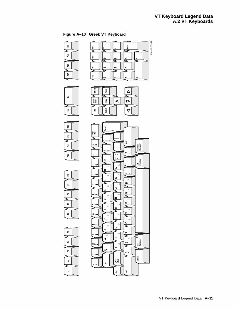
VT Keyboard Legend DataA.2 VT Keyboards
Figure A–10 Greek VT Keyboard
3
45
6
78
9
..
21 0PF
1PF
2PF
3PF
4
Enter− ,
DoHe
lpF1
7F1
9F2
0F1
8
Retu
rn
Shift
1
Alt
Func
tion
Shift
Ctrl
Tab
Gree
kAl
tFu
nctio
nCo
mpo
seCh
arac
ter
F11
F12
F13
F14
F2F3
F4F1
F5F6
F7F8
F9F1
0
Rem
ove
Selec
tPr
evNe
xt
Find
Inse
rtHe
re1
~!
−=
_+
[V
Q{
} ]
AS
DF
GH
JK
L"
| \A
..: ;
<Z
>Z
XC
VB
NM
, ,. .
? /
´
@#
$%
^&
*(
W
)
ER
TY
UI
OP
CY
WB
NM
DF
GH
KL
SX
E
23
45
67
89
0
IQ
PR
TU
O
MA−
0327
−93.
GRA
VT Keyboard Legend Data A–11
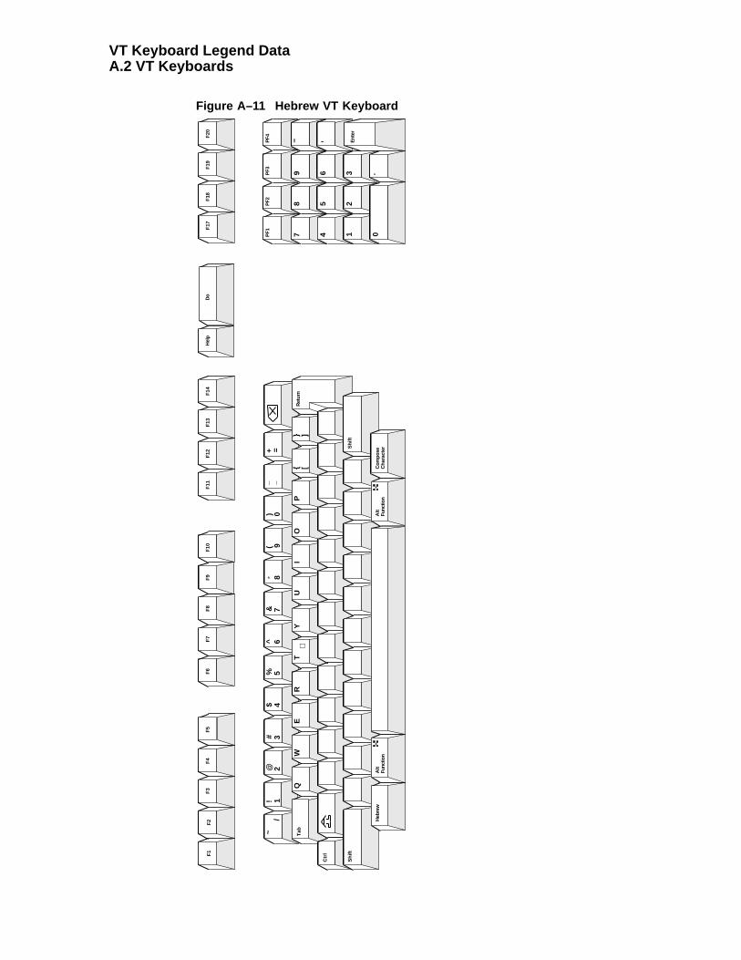
VT Keyboard Legend DataA.2 VT Keyboards
Figure A–11 Hebrew VT Keyboard
3
45
6
78
9
..
21 0PF1
PF2
PF3
PF4
Ent
er
− ,
Do
Hel
pF
17F
19F
20F
18
Ret
urn
Shi
ft
1
Alt
Func
tion
Shi
ft
Ctr
l
Tab
Heb
rew
Alt
Func
tion
Com
pose
Cha
ract
er
F11
F12
F13
F14
F2
F3
F4
F1
F5
F6
F7
F8
F9
F10
12
34
56
78
90
~!
@#
$%
^&
*(
)_ −
+ =/
QW
ER
TU
IO
PY
{ [} ]
ℵå
טí
ïפ
÷ר
AS
DF
GH
JK
L: ;
"| \
,;
גד
çי
êë
לע
óש
ZX
CV
BN
M<>
,.
? /.
,.
בה
æמ
נñ
õö
ú
Rem
ove
Sel
ect
Pre
vN
ext
Find
Inse
rtH
ere
A–12 VT Keyboard Legend Data

VT Keyboard Legend DataA.2 VT Keyboards
Figure A–12 Hungarian VT Keyboard
3
45
6
78
9
..
21 0PF
1PF
2PF
3PF
4
Enter− ,
DoHe
lpF1
7F1
9F2
0F1
8
Retu
rn
Shift
1
Alt
Func
tion
Shift
Ctrl
Tab
Com
pose
Char
acte
rAl
tFu
nctio
nCo
mpo
seCh
arac
ter
F11
F12
F13
F14
F2F3
F4F1
F5F6
F7F8
F9F1
0
Rem
ove
Selec
tPr
evNe
xt
Find
Inse
rtHe
re1
2@
3#
4$
6^
7&
89
*(
0Ó
)Ö
+Ü
+"
!/
==
−!
5%_
~
W} ]
{ [O
Ú
AÁ
É\|
U: ;
"
> <N
? /.
Í,
:_ −
<>
QE
RT
IO
PU
Z
SD
FG
HJ
KL
XC
VB
M?
Y
MA−
0328
−93.
GRA
VT Keyboard Legend Data A–13

VT Keyboard Legend DataA.2 VT Keyboards
Figure A–13 Italian VT Keyboard
F1
F2
F3
F5
78
9
45
6 32
1 0
LJ-
03
32
6-T
I0
Z
XC
VB
N
AS
DF
GH
JK
L
IO
PT
YU
W
ER
M
Q
> <
F4
F6
F7
F8
F1
0F
9F
11
F1
2F
13
F1
4F
17
F1
8F
19
F2
0
PF
1P
F2
PF
3P
F4
_ ,
X
Alt
Alt
Ta
b
Co
ntr
~
.
Gu
ida
Ese
cuzi
on
e
Pre
cS
ucc
Ca
nce
lIn
ser
Ric
er
Se
lez
Inv
ioin
12
34
56
78
90
!
#
$
%
&
*
()
a
?/
.:
\
]-+
=
]
e
<
uS
S
a
o,.
,
e
}
{
Co
mp
os
.c
ara
tte
reC
om
po
s.
ca
ratt
ere
"
A–14 VT Keyboard Legend Data
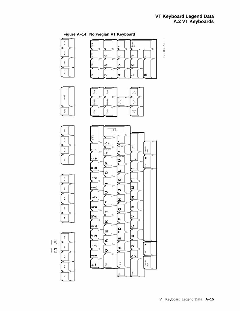
VT Keyboard Legend DataA.2 VT Keyboards
Figure A–14 Norwegian VT Keyboard
F1
F2
F3
F5
78
9
45
6 32
1 0
LJ-
03
32
7-T
I0
ZX
CV
BN
AS
DF
GH
JK
L
IO
PT
YU
WE
R
M
Q
> <
F4
F6
F7
F8
F1
0F
9F
11
F1
2F
13
F1
4F
17
F1
8F
19
F2
0
PF
1P
F2
PF
3P
F4
_ ,
X
Alt
Alt
Sp
es
ial
teg
n
Ta
b
Ktr
l
.
Hje
lp
Tilb
ake
Fre
m
Fin
n
Ve
lg
Le
gg
inn
Inn
sett
Fje
rn1
23
45
67
89
0!
#$
%&
()
a ~?
/
.:-+
=
}]A
<
Utf
rO
Sk
ift
Sp
es
ial
teg
n
,;S
kif
t
*\
O|
[ {
"
"
VT Keyboard Legend Data A–15

VT Keyboard Legend DataA.2 VT Keyboards
Figure A–15 Polish VT Keyboard
3
45
6
78
9
..
21 0PF
1PF
2PF
3PF
4
Enter− ,
DoHe
lpF1
7F1
9F2
0F1
8
Retu
rn
Shift
1
Alt
Func
tion
Shift
Ctrl
Tab
Com
pose
Char
acte
rAl
tFu
nctio
nCo
mpo
seCh
arac
ter
F11
F12
F13
F14
F2F3
F4F1
F5F6
F7F8
F9F1
0
Rem
ove
Selec
tPr
evNe
xt
Find
Inse
rtHe
re1
~!
@#
$%
^&
*(
)_ −
+ =
QW
ER
{ [} ]
EO’
A: ;
"|
AS’
L\
Z<
,.
? /Z.
Z’C’
N’>
><
TU
IO
PY
SD
FG
HJ
KL
XC
VB
NM
23
45
67
89
0
MA−
0330
−93.
GRA
A–16 VT Keyboard Legend Data

VT Keyboard Legend DataA.2 VT Keyboards
Figure A–16 Portuguese VT Keyboard
F1
F2
F3
F5
78
9
45
6 32
1 0
LJ-
03
32
8-T
I0
12
34
56
78
90
ZX
CV
BN
AS
DF
GH
JK
L
IO
PT
YU
WE
R
M
Q
> <
F4
F6
F7
F8
F1
0F
9F
11
F1
2F
13
F1
4F
17
F1
8F
19
F2
0
PF
1P
F2
PF
3P
F4
_
,
X!
#$
%&
*(
)a
+ =
_ - ? /
} ]
Alt
Co
mp
os
eC
ha
rac
ter
Ta
b
Ctr
l.
Sh
ift
Pre
vN
ext
Re-
mo
veIn
sert
He
reF
ind
Se
lec
t
En
ter
~
.,
:
\
} ]
.
>
Re
turn
"
He
lpD
o
Fu
nc
tio
nA
ltF
un
cti
on
Co
mp
os
eC
ha
rac
ter
Sh
ift
,
VT Keyboard Legend Data A–17
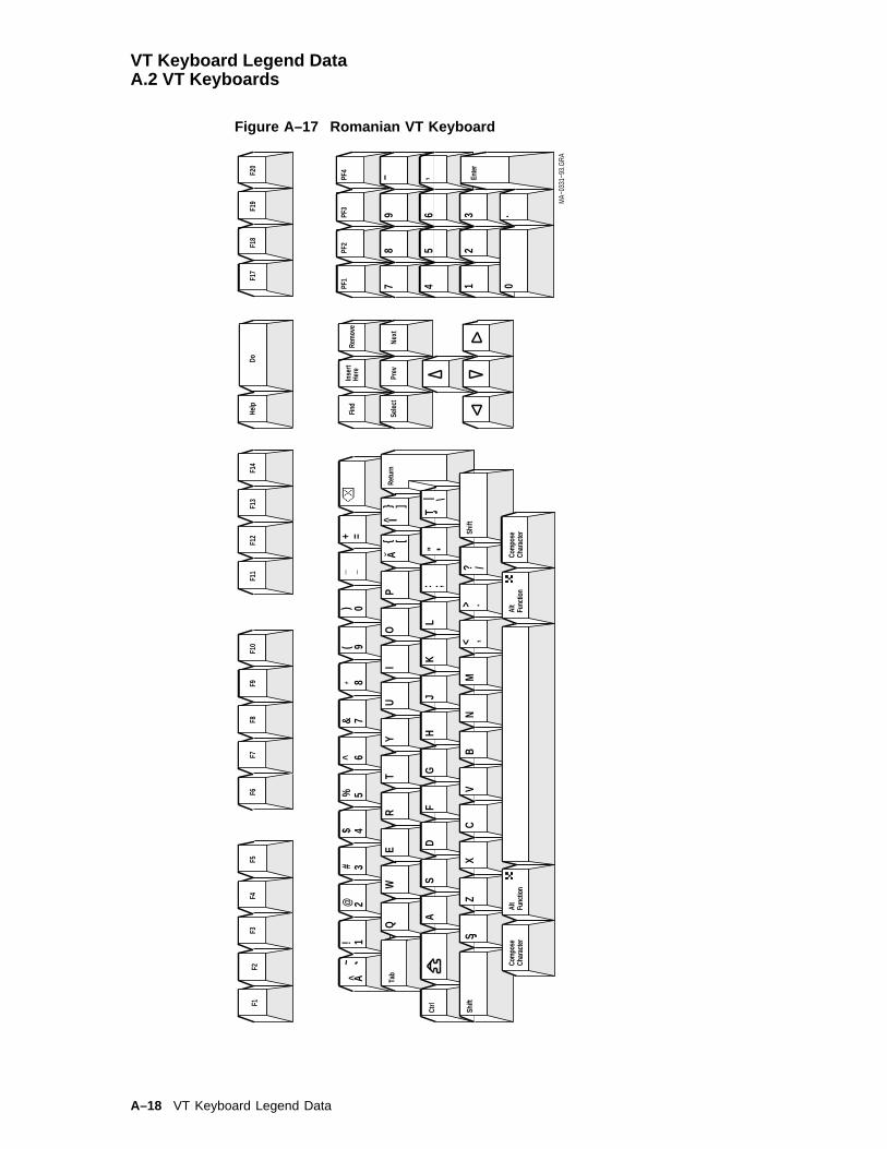
VT Keyboard Legend DataA.2 VT Keyboards
Figure A–17 Romanian VT Keyboard
3
45
6
78
9
..
21 0PF
1PF
2PF
3PF
4
Enter− ,
DoHe
lpF1
7F1
9F2
0F1
8
Retu
rn
Shift
1
Alt
Func
tion
Shift
Ctrl
Tab
Com
pose
Char
acte
rAl
tFu
nctio
nCo
mpo
seCh
arac
ter
F11
F12
F13
F14
F2F3
F4F1
F5F6
F7F8
F9F1
0
Rem
ove
Selec
tPr
evNe
xt
Find
Inse
rtHe
re2
~!
@^
*(
)_ −
+ =A
{ [} ]
A
A: ;
"| \
T
Z<
>,
.? /
S13
45
67
89
0#
$%
&
QW
ER
TU
IO
PY
SD
FG
HJ
KL
I
XC
VB
NM
MA−
0331
−93.
GRA
A–18 VT Keyboard Legend Data
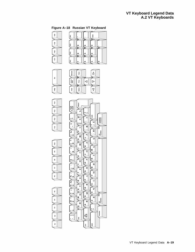
VT Keyboard Legend DataA.2 VT Keyboards
Figure A–18 Russian VT Keyboard
3
45
6
78
9
..
21 0PF1
PF2
PF3
PF4
Ent
er
− ,
Do
Hel
pF
17F
19F
20F
18
Ret
urn
Shi
ft
1
Alt
Func
tion
Shi
ft
Ctr
l
Tab
Rus
sian
Alt
Func
tion
Com
pose
Cha
ract
er
F11
F12
F13
F14
F2
F3
F4
F1
F5
F6
F7
F8
F9
F10
Rem
ove
Sel
ect
Pre
vN
ext
Find
Inse
rtH
ere
2~
!@
^*
_ −+ =
( )"
/’
.;
?
Q{ [
} ]Й
A;
| \П
"
N,
./
<>Я
,.
#$
%&
()
№:
%§
WE
RT
UI
OP
Y
SD
FG
HJ
KL
:
ZX
CV
BM
?
13
45
67
89
0
ЦУ
КЕ
НГ
ШЩ
ЗХ
Ъ
ФЫ
ВА
РО
ЛД
ЖЭ
ЧС
МИ
ТЬ
БЮ
Ё
VT Keyboard Legend Data A–19

VT Keyboard Legend DataA.2 VT Keyboards
Figure A–19 SCS VT Keyboard
3
45
6
78
9
..
21 0PF
1PF
2PF
3PF
4
Enter− ,
DoHe
lpF1
7F1
9F2
0F1
8
Retu
rn
Shift
1
Alt
Func
tion
Shift
Ctrl
Tab
Com
pose
Char
acte
rAl
tFu
nctio
nCo
mpo
seCh
arac
ter
F11
F12
F13
F14
F2F3
F4F1
F5F6
F7F8
F9F1
0
Rem
ove
Selec
tPr
evNe
xt
Find
Inse
rtHe
re~
−_+
{ [} ]
Q
A:
"| \
Z_ −
<>
? /; ,
: .<>
@^
*(
)=
"
SD
C
−=
;
1!* +
()
&#
$%
&?
WE
RT
UI
OP
Y
SD
FG
HJ
KL
XC
VB
NM
23
45
67
89
0/
’ CZ
MA−
0333
−93.
GRA
A–20 VT Keyboard Legend Data

VT Keyboard Legend DataA.2 VT Keyboards
Figure A–20 Slovak VT Keyboard
3
45
6
78
9
..
21 0PF
1PF
2PF
3PF
4
Enter− ,
DoHe
lpF1
7F1
9F2
0F1
8
Retu
rn
Shift
1
Alt
Func
tion
Shift
Ctrl
Tab
Com
pose
Char
acte
rAl
tFu
nctio
nCo
mpo
seCh
arac
ter
F11
F12
F13
F14
F2F3
F4F1
F5F6
F7F8
F9F1
0
Rem
ove
Selec
tPr
evNe
xt
Find
Inse
rtHe
re@
#^
*{
}% =
ya
e..
sc
tz
’’
’’
Iu/
[(
]a..
’
A§
";
!)
on
B? ,
><
: .−
| \
_
~1 +
l’3
45
67
80
2
QW
ER
TU
OP
Z
SD
FG
HJ
KL
XC
VN
MY
$%
&9 ´
MA−
0334
−93.
GRA
VT Keyboard Legend Data A–21

VT Keyboard Legend DataA.2 VT Keyboards
Figure A–21 Spanish VT Keyboard
F1
F2
F3
F5
78
9
45
6 32
1 0
ZX
CV
BN
AS
DF
GH
JK
L
IO
PT
YU
WE
R
M
Q
> <
F4
F6
F7
F8
F1
0F
9F
11
F1
2F
13
F1
4F
17
F1
8F
19
F2
0
PF
1P
F2
PF
3P
F4 _
X
CT
RL
Va
li-
da
r
Ayu
da
Eje
cuta
r
12
34
56
78
90
%&
()
?/
.:=
,;_
Pre
via
Bo
rra
rIn
ser-
tar
Lo
ca-
Se
lec
-
,
!#
$
*
a
~
Co
mp
on
er
ca
rac
ter
Ta
bu
lac
ion
Ca
mb
iar
?\]
-
+]
liza
r
cio
na
r
!
~
:
N
<
a o
Pre
via
Sig
te.
Fu
nc
ion
Alt
{{
Ca
mb
iar
Co
mp
on
er
ca
rac
ter
Fu
nc
ion
Alt
LJ-
03
27
6-T
I0
.
"
A–22 VT Keyboard Legend Data

VT Keyboard Legend DataA.2 VT Keyboards
Figure A–22 Swedish VT Keyboard
LJ-
03
23
3-T
I0
F1
F2
F3
F5
78
9
45
6 32
1 0
ZX
CV
BN
AS
DF
GH
JK
L
IO
PT
YU
WE
R
M
Q
> <
F4
F6
F7
F8
F1
0F
9F
11
F1
2F
13
F1
4F
17
F1
8F
19
F2
0
PF
1P
F2
PF
3P
F4
_ ,
X
Ctr
l
Hja
lpU
tfo
r
12
34
56
78
90
%&
()
?/
.:=
,;_
!$
Ta
b
Sk
ift
-S
kif
t
Fo
reg
Na
sta
Ta
bo
rtS
att
inS
ok Va
lj
En
ter
.
*
a
~
Ko
mb
ine
ra
}+
}
S
S
AO
....
.. ....
..
..
tec
ke
n<
ut
Alt
ern
ati
vfu
nk
tio
nA
lte
rna
tiv
fun
kti
on
Ko
mb
ine
rate
ck
en
#\
]]
AU..
"
....
VT Keyboard Legend Data A–23
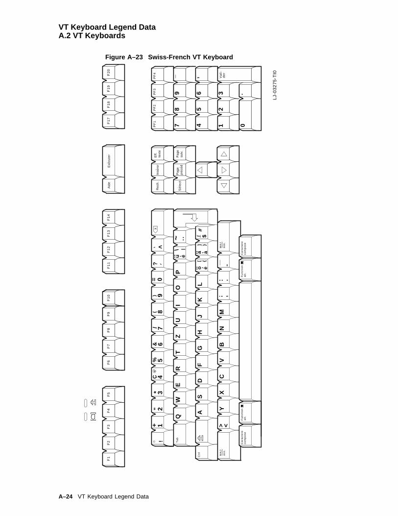
VT Keyboard Legend DataA.2 VT Keyboards
Figure A–23 Swiss-French VT Keyboard
F1
F2
F3
F5
78
9
45
6 32
1 0
YX
CV
BN
AS
DF
GH
JK
L
IO
PT
ZU
WE
R
M
Q
> <
F4
F6
F7
F8
F1
0F
9F
11
F1
2F
13
F1
4F
17
F1
8F
19
F2
0
PF
1P
F2
PF
3P
F4 _ ,
X
Ta
b
Ctr
l
Eff
.te
xte
Inse
rer
Re
ch.
Se
lec
t
Va
li-
de
rM
AJ
.m
in.
Aid
eE
xecu
ter
MA
J.
min
.
Pa
ge
pre
ced
Pa
ge
suiv
.
12
34
56
78
90
!
#$
%&
*(
)a
~
Ca
rac
tere
?/
.:
\
]
-
+=
]
,
co
mp
os
e
:
<
u..
.... a
e
o ea
;
}{
|
Fu
nc
tio
na
lt.
Fu
nc
tio
na
lt.
Ca
rac
tere
co
mp
os
e.
LJ-
03
27
5-T
I0
"C
A–24 VT Keyboard Legend Data
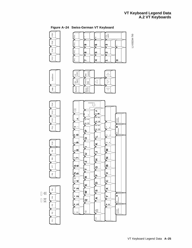
VT Keyboard Legend DataA.2 VT Keyboards
Figure A–24 Swiss-German VT Keyboard
LJ-
03
23
4-T
I0
F1
F2
F3
F5
78
9
45
6 32
1 0
YX
CV
BN
AS
DF
GH
JK
L
IO
PT
ZU
WE
RQ
> <
F4
F6
F7
F8
F1
0F
9F
11
F1
2F
13
F1
4F
17
F1
8F
19
F2
0
PF
1P
F2
PF
3P
F4
_ ,
X
Ctr
l
Hilf
eA
usf
uh
ren
Bild
BildLo
-sc
he
nE
in-
fug
en
Su
che
n
Se
lek
-
Ein
-
12
34
56
78
90
%&
()
.:=..
\
ga
be
tie
ren
..
M
!
#$
*a
~
Ko
mb
i-
?
\ ]
-
+
]u..
<z
eic
he
n
e
e o.a..a
.
..
,,.
|
{}
Alt
Fu
nk
tio
nA
ltF
un
kti
on
Ko
mb
i-z
eic
he
n.
..
"
VT Keyboard Legend Data A–25
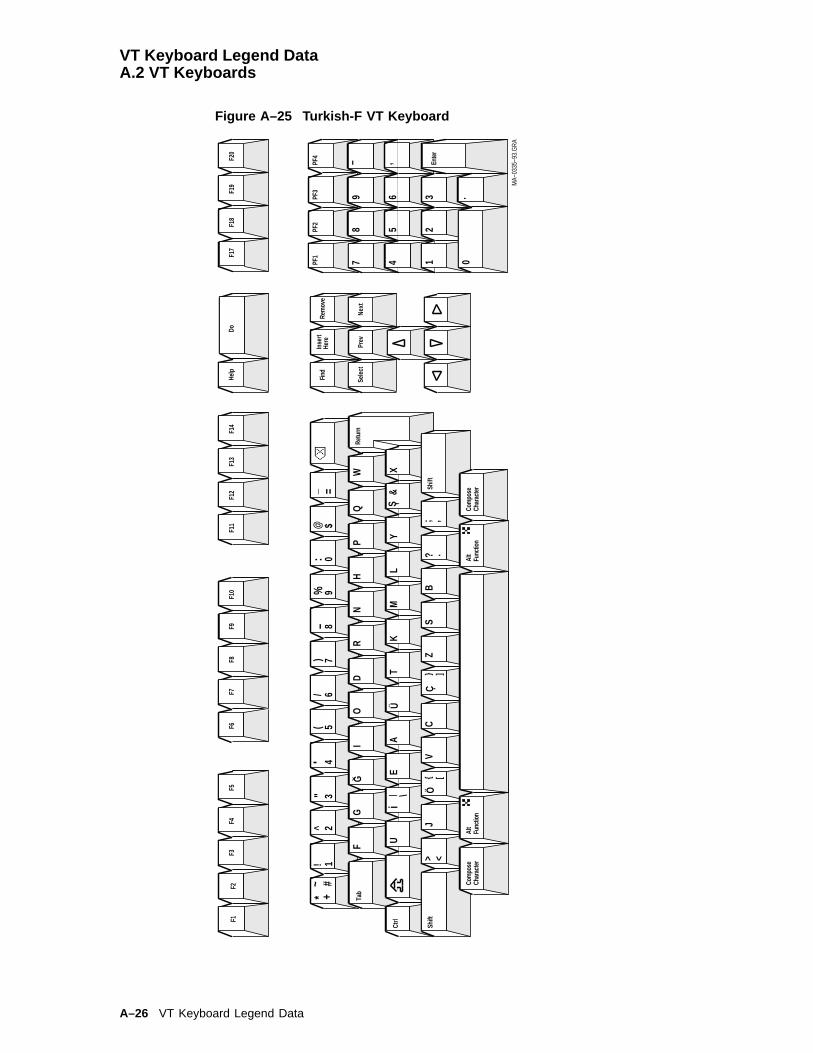
VT Keyboard Legend DataA.2 VT Keyboards
Figure A–25 Turkish-F VT Keyboard
3
45
6
78
9
..
21 0PF
1PF
2PF
3PF
4
Enter− ,
DoHe
lpF1
7F1
9F2
0F1
8
Retu
rn
Shift
Alt
Func
tion
Shift
Ctrl
Tab
Com
pose
Char
acte
rAl
tFu
nctio
nCo
mpo
seCh
arac
ter
F11
F12
F13
F14
F2F3
F4F1
F5F6
F7F8
F9F1
0
Rem
ove
Selec
tPr
evNe
xt
Find
Inse
rtHe
re!
^"
* +#~
−_ =
IG
Ui
ÜS ,
| \
> <J
Ö{ [
}Ç
].?
; ,
FG
OD
RN
HP
QW
EA
TK
ML
YX
&
VC
ZS
B
1(
/)
%:
@5
23
46
78
90
$
MA−
0335
−93.
GRA
A–26 VT Keyboard Legend Data

VT Keyboard Legend DataA.2 VT Keyboards
Figure A–26 Turkish-Q VT Keyboard
3
45
6
78
9
..
21 0PF
1PF
2PF
3PF
4
Enter− ,
DoHe
lpF1
7F1
9F2
0F1
8
Retu
rn
Shift
1
Alt
Func
tion
Shift
Ctrl
Tab
Com
pose
Char
acte
rAl
tFu
nctio
nCo
mpo
seCh
arac
ter
F11
F12
F13
F14
F2F3
F4F1
F5F6
F7F8
F9F1
0
Rem
ove
Selec
tPr
evNe
xt
Find
Inse
rtHe
re@~
1!G
^−
*
Q;
"
A+ =
}{
][
> <Z
| \i
− ,.
/$
%(
)#
Ü&
Ö
WE
RT
YU
IO
P:
SD
FG
HJ
KL
ÇS ,
XC
VB
NM
?
23
45
67
89
0I
i
MA−
0336
−93.
GRA
VT Keyboard Legend Data A–27


BEnhanced PC Keyboards
This appendix shows the non-spacing diacritical marks and the keyboard layoutsfor VT520 Enhanced PC keyboards.
B.1 Summary of Non-Spacing Diacritical MarksTable B–1 lists the non-spacing diacritical marks within square brackets [ ].
Table B–1 Enhanced PC Keyboard Non-Spacing Diacritical Marks
EPC Keyboard Acute Breve Caron Cedilla Circumflex Dieresis Dot
Austrian/German [´] [^]
Belgian [´] [^] [¨]
Canadian (French) [´] [¸] [^] [¨]
Czech [´] [_] [¨]
Danish [´] [^] [¨]
Dutch [´] [¸] [^] [¨]
Finnish [´] [^] [¨]
French [^] [¨]
Greek [¨]
Hebrew (none)
Hungarian [´] [^] [_] [¸] [^] [¨] [�]
Italian (none)
Latin American [´] [^] [¨]
Norwegian [´] [^] [¨]
Polish [´]
Portuguese [´] [^] [¨]
Romanian [´] [^] [_] [¸] [^] [¨] [�]
Russian (none)
SCS (none)
Slovak [´] [_] [¨]
Spanish [´] [^] [¨]
Swedish [´] [^] [¨]
Swiss-French [´] [^] [¨]
Swiss-German [´] [^] [¨]
Turkish-Q
(continued on next page)
Enhanced PC Keyboards B–1
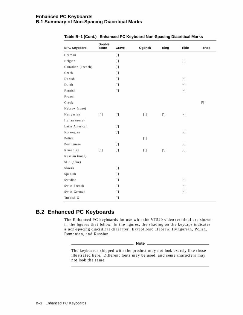
Enhanced PC KeyboardsB.1 Summary of Non-Spacing Diacritical Marks
Table B–1 (Cont.) Enhanced PC Keyboard Non-Spacing Diacritical Marks
EPC KeyboardDoubleacute Grave Ogonek Ring Tilde Tonos
German [`]
Belgian [`] [~]
Canadian (French) [`]
Czech [`]
Danish [`] [~]
Dutch [`] [~]
Finnish [`] [~]
French
Greek [!]
Hebrew (none)
Hungarian [00] [`] [�] [°] [~]
Italian (none)
Latin American [`]
Norwegian [`] [~]
Polish [�]
Portuguese [`] [~]
Romanian [00] [`] [�] [°] [~]
Russian (none)
SCS (none)
Slovak [`]
Spanish [`]
Swedish [`] [~]
Swiss-French [`] [~]
Swiss-German [`] [~]
Turkish-Q [`]
B.2 Enhanced PC KeyboardsThe Enhanced PC keyboards for use with the VT520 video terminal are shownin the figures that follow. In the figures, the shading on the keycaps indicatesa non-spacing diacritical character. Exceptions: Hebrew, Hungarian, Polish,Romanian, and Russian.
Note
The keyboards shipped with the product may not look exactly like thoseillustrated here. Different fonts may be used, and some characters maynot look the same.
B–2 Enhanced PC Keyboards

Enhanced PC KeyboardsB.2 Enhanced PC Keyboards
Figure B–1 Austrian/German Enhanced PC Keyboard
Bild
Po
s 1
Ein
fg
Es
cF
1F
2F
3F
4F
5F
6F
7F
8F
9F
10
F1
1F
12
Dru
ckR
olle
n
S-A
bf
Un
tbr
Pa
use
En
de
En
tf
Po
s 1
Bild
_
Bild
En
de
Ein
fgE
ntf
Num 7
89
45
6 32
1 0
+ En
ter
Bild
x ,
Wes
t G
erm
any
22
LJ-
03
21
2-T
I0
Num
Ro
llen
_
12
34
56
78
90
!
#
$%
&
*
()
a
-
+
=
~Z
XC
VB
N
AS
DF
GH
JK
L
IO
PT
Y
UW
ER
M
Q
?/
.,
:;
"\
}]
}]
Str
g
S
S
32
O
U
..A..
µ|
> <
Str
gA
ltA
ltG
r
..
^
Enhanced PC Keyboards B–3
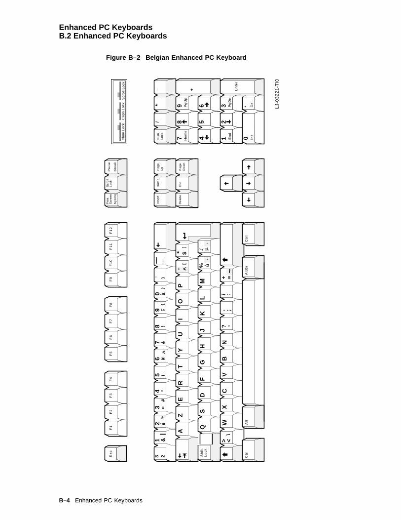
Enhanced PC KeyboardsB.2 Enhanced PC Keyboards
Figure B–2 Belgian Enhanced PC Keyboard
Pa
ge
Up
Ho
me
Inse
rt
Es
cF
1F
2F
3F
4F
5F
6F
7F
8F
9F
10
F1
1F
12
Pri
nt
Scr
ee
nS
cro
llL
ock
Sy
sR
qB
rea
k
Pa
use
Pa
ge
Do
wn
End
De
lete
Ho
me
Pg
Up
_
Pg
Dn
En
d
Ins
De
l
Num
Lo
ck
78
9
45
6 32
1 0
+ En
ter
*/
.
Bel
giu
m1
8
LJ-
03
22
1-T
I0
Nu
m L
ock
Ca
ps
Lo
ckS
cro
ll L
ock
12
34
56
78
90
!#
%
&(
)a
=~
WX
CV
BN
QS
DF
GH
JK
L
IO
PT
YU
ZE
R
M
A
?/
.
"
]
]
Lo
ck
:;
Ctr
lC
trl
S
S
|
^$
}{
..*
+’
C^
Sh
ift
23e
ea
uµ
Alt
Alt
Gr
\> <
B–4 Enhanced PC Keyboards

Enhanced PC KeyboardsB.2 Enhanced PC Keyboards
Figure B–3 British/U.K. Enhanced PC Keyboard
Pa
ge
Up
Ho
me
Inse
rt
Es
cF
1F
2F
3F
4F
5F
6F
7F
8F
9F
10
F1
1F
12
Pri
nt
Scr
ee
nS
cro
llL
ock
Sy
sR
qB
rea
k
Pa
use
Pa
ge
Do
wn
End
De
lete
Ho
me
Pg
Up
_/
Pg
Dn
En
d
Ins
De
l
Num
Lo
ck
78
9
45
6 32
1 0.
+ En
ter
*
Un
ited
Kin
gd
om
LJ-
03
21
9-T
I0
17
Nu
m L
ock
Ca
ps
Lo
ckS
cro
ll L
ock
12
34
56
78
90
!
#
$%
^&
*(
)
a
-+ =
~
ZX
CV
BN
AS
DF
GH
JK
L
IO
PT
YU
WE
R
M
Q
? /.
,
: ;
"
} ]
} ]>
<
Ctr
l
|
| \
Ctr
lA
ltG
rA
lt
Ca
ps
Lo
ck
Enhanced PC Keyboards B–5

Enhanced PC KeyboardsB.2 Enhanced PC Keyboards
Figure B–4 Canadian-English/North American Enhanced PC Keyboard
Pa
ge
Up
Ho
me
Inse
rt
Es
cF
1F
2F
3F
4F
5F
6F
7F
8F
9F
10
F1
1F
12
Pri
nt
Scr
ee
nS
cro
llL
ock
Sy
sR
qB
rea
k
Pa
use
Pa
ge
Do
wn
End
De
lete
Ho
me
Pg
Up
_/
Pg
Dn
En
d
Ins
De
l
Num
Lo
ck
78
9
45
6 32
1 0.
+ En
ter
*
No
rth
Am
eric
an1
6
Nu
m L
ock
Ca
ps
Lo
ckS
cro
ll L
ock
LJ-
03
21
8-T
I0
12
34
56
78
90
!#
$%
^&
*(
)a
-+ =
~
ZX
CV
BN
AS
DF
GH
JK
L
IO
PT
YU
WE
R
M
Q
? /.
,
: ;"} ]
Ca
ps
Ta
b Sh
ift
><
Ctr
lC
trl
_
Alt
Alt
Lo
ck
En
ter\
} ]
Sh
ift
B–6 Enhanced PC Keyboards
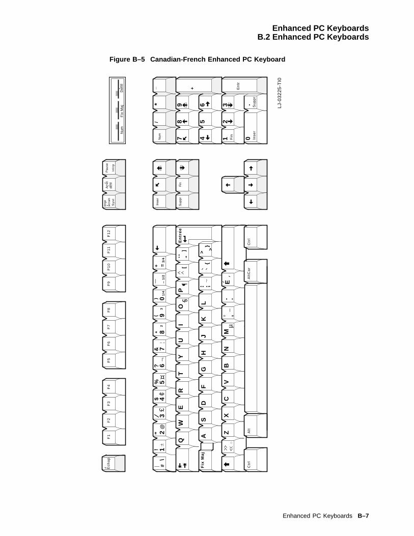
Enhanced PC KeyboardsB.2 Enhanced PC Keyboards
Figure B–5 Canadian-French Enhanced PC Keyboard
Inse
r
Ec
ha
pF
1F
2F
3F
4F
5F
6F
7F
8F
9F
10
F1
1F
12
Imp
re
cra
nA
rre
td
efil
Sy
st
Intr
p
Pa
use
Fin
Su
pp
r
_/
Fin
Inse
r
Num 7
89
45
6 32
1 0
+ En
tr
* Su
pp
r
LJ-
03
22
5-T
I0
Num
De
fill
Fix
Ma
j .
*+ =
@#
12
34
56
78
90
!$
%&
()
Y
XC
VB
N
AS
DF
GH
JK
L
IO
PT
Z
UW
ER
M
Q
?
,
"\
Ctr
l
1/2
µ
Fre
nc
h/C
an
ad
ian
Ctr
lA
ltA
ltC
ar
..
. .E.
,
..>
}
>
}
]
]
3/4
1/4
32
En
tre
e
Fix
Ma
j,
Enhanced PC Keyboards B–7
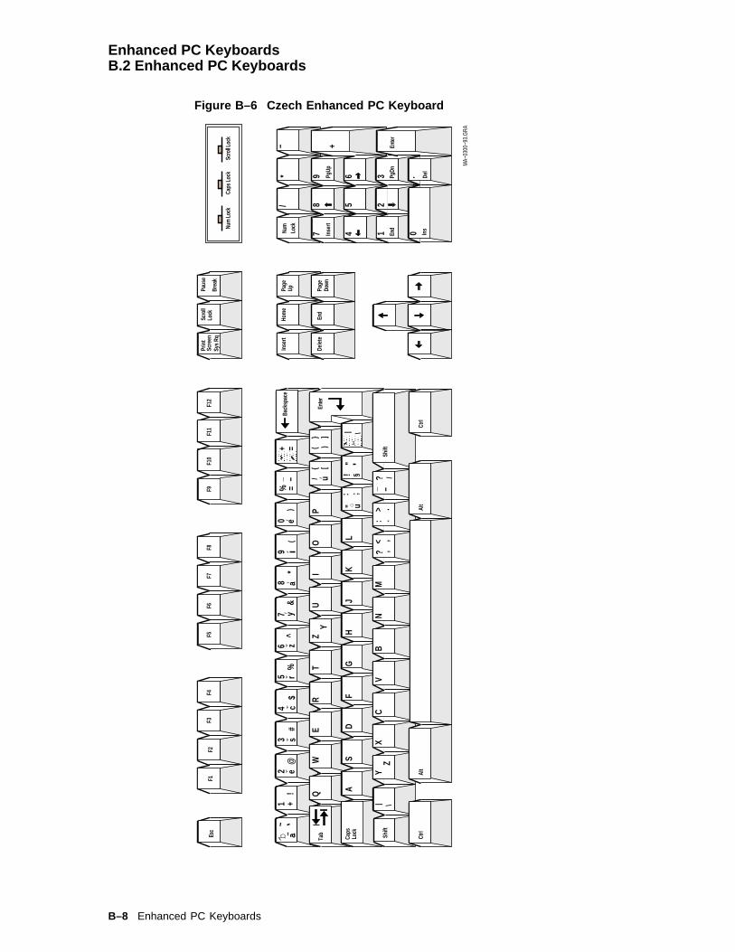
Enhanced PC KeyboardsB.2 Enhanced PC Keyboards
Figure B–6 Czech Enhanced PC Keyboard
1/
*−
3
45
6
78
9
+
.
Del
Inse
rtPg
Up
PgDn
.
Enter
Ctrl
Lock
Caps
Alt
Alt
Ins
Ctrl
Num
Lock
Caps
Lock
Scro
ll Loc
k
End
21 0Nu
mLo
ck
Inse
rt
Delet
e
Hom
e
End
Page
Up Page
Down
F9F1
1F1
2F1
0F5
F6F7
F8F2
F3F4
F1Es
c
Shift
Tab
Back
spac
e
Enter
Scre
en
Shift
Scro
llLo
ckPa
use
Sys R
qBr
eak
!~
1 +2
@e
3#
s4
$c
5%
rz
^6
7&
y’8
*a’
( 9
0 e’)
=%_ −
+ =a..b
QW
ER
TY
ZU
IO
P{
u[
/ ’}
( )]
AS
DF
GH
JK
L"
;u
:|
"\
! §
\Y
ZX
CV
BN
M,?
< ,>
: ..
−_? /
|
MA−
0300
−93.
GRA
´
..
B–8 Enhanced PC Keyboards

Enhanced PC KeyboardsB.2 Enhanced PC Keyboards
Figure B–7 Danish Enhanced PC Keyboard
Pa
ge
Up
Ho
me
Inse
rt
Es
cF
1F
2F
3F
4F
5F
6F
7F
8F
9F
10
F1
1F
12
Pri
nt
Scr
ee
nS
cro
llL
ock
Sy
sR
qB
rea
k
Pa
use
Pa
ge
Do
wn
End
De
lete
Ho
me
Pg
Up
_
Pg
Dn
En
d
Ins
De
l
Num
Lo
ck
78
9
45
6 32
1 0’
+ En
ter
*/
Den
mar
k1
9
LJ-
03
22
2-T
I0
Nu
m L
ock
Ca
ps
Lo
ckS
cro
ll L
ock
_
12
34
56
78
90
!#
%&
()
a
-
=
ZX
CV
BN
AS
DF
GH
JK
L
IO
PT
YU
WE
R
M
Q
?/
.,
"]
]
:;
Ctr
lC
trl
S
S
$}
{
*
21
A
+
O
\> <
Alt
Alt
Gr
Ca
ps
Lo
ck
..~
|
Enhanced PC Keyboards B–9
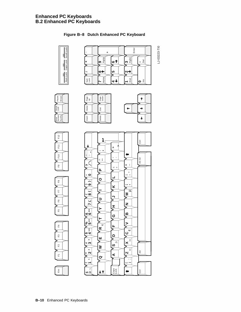
Enhanced PC KeyboardsB.2 Enhanced PC Keyboards
Figure B–8 Dutch Enhanced PC Keyboard
Pa
ge
Up
Ho
me
Inse
rt
Es
cF
1F
2F
3F
4F
5F
6F
7F
8F
9F
10
F1
1F
12
Pri
nt
Scr
ee
nS
cro
llL
ock
Sy
sR
qB
rea
k
Pa
use
Pa
ge
Do
wn
End
De
lete
Ho
me
Pg
Up
_
Pg
Dn
En
d
Ins
De
l
Num
Lo
ck
78
9
45
6 32
1 0
+ En
ter
*/
LJ-
03
22
3-T
I0
*
=
@1
23
45
67
89
0!
$%
&(
)
Y
XC
VB
N
AS
DF
GH
JK
L
IO
PT
Z
UW
ER
M
Q
?"
Ctr
l
1/2
µ
Ctr
lA
ltA
lt G
r
..
.
>
}
>
}
]]
3/4
1/4
32
, ,
1#
, .. ..
,
Nu
m L
ock
Ca
ps
Lo
ckS
cro
ll L
ock
Ca
ps
Lo
ck
,
B–10 Enhanced PC Keyboards
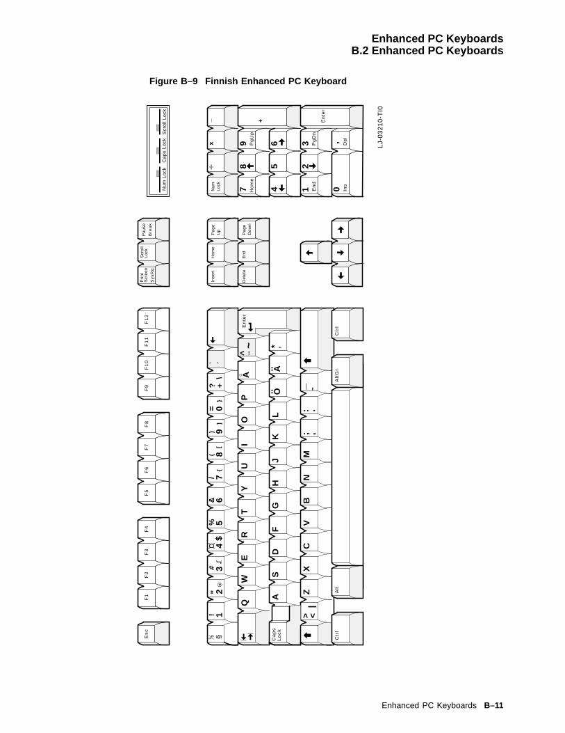
Enhanced PC KeyboardsB.2 Enhanced PC Keyboards
Figure B–9 Finnish Enhanced PC Keyboard
Pa
ge
Up
Ho
me
Inse
rt
Es
cF
1F
2F
3F
4F
5F
6F
7F
8F
9F
10
F1
1F
12
Pri
nt
Scr
ee
nS
cro
llL
ock
Sy
sR
qB
rea
k
Pa
use
Pa
ge
Do
wn
End
De
lete
Ho
me
Pg
Up
_
Pg
Dn
En
d
Ins
De
l
Num
Lo
ck
78
9
45
6 32
1 0’
+ En
ter
Sw
eden
/Fin
lan
d2
0
LJ-
03
21
0-T
I0
Nu
m L
ock
Ca
ps
Lo
ckS
cro
ll L
ock
_
12
34
56
78
90
!#
%&
()
a
-
=
ZX
CV
BN
AS
DF
GH
JK
L
IO
PT
YU
WE
R
M
Q
?/
.,
"\
]
]
:;
Ctr
l
S
S
$}
{2
1
O..
+
|> <
Alt
Gr
Ca
ps
Lo
ck
*A..
AE
nte
r..
~
Alt
Ctr
l
x
Enhanced PC Keyboards B–11

Enhanced PC KeyboardsB.2 Enhanced PC Keyboards
Figure B–10 French Enhanced PC Keyboard
Inse
r
Ec
ha
pF
1F
2F
3F
4F
5F
6F
7F
8F
9F
10
F1
1F
12
Imp
re
cra
nA
rre
td
efil
Sy
st
Att
n
Pa
use
Fin
Su
pp
r
_/
Fin
Inse
r
Ve
rrN
um 78
9
45
6 32
1 0
+ En
tr
* Su
pp
r
Fre
nch
21
LJ-
03
21
1-T
I0
Num
De
fill
_1
34
56
89
0
!
#
$
%
&
*
()
+ =
WX
CV
BN
QS
DF
GH
JK
L
IO
PT
YU
ZE
R
M
A
?/
.,
:;
"\
}]
Ctr
lC
trl
|2
a
En
tre
e
^
S
S
u
µ
-a
> <
Alt
Alt
Alt
Gr
^..
7 e2
~e
,
B–12 Enhanced PC Keyboards
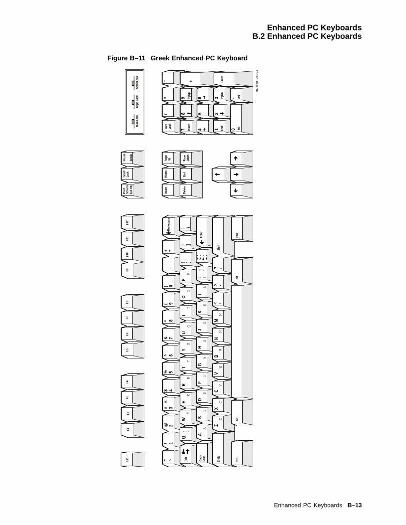
Enhanced PC KeyboardsB.2 Enhanced PC Keyboards
Figure B–11 Greek Enhanced PC Keyboard
Num
Loc
kCa
ps L
ock
Scro
ll Loc
k
Inse
rt
Dele
te
Hom
e
End
Page
Up Page
Down
Prin
tSc
reen
Scro
llLo
ckPa
use
Sys
RqBr
eak
F9F1
1F1
2F1
0F5
F6F7
F8F2
F3F4
F1Es
c
Lock
/*
−
3
45
6
78
9
+
.
Del
Inse
rtPg
Up
PgDn
.
Ente
r
Ins
End
21 0Nu
mLo
ck
Tab
Alt
Ctrl
Shift
Alt
Ctrl
Shift
Caps
Back
spac
e9
0(
)=+
~1!
2@3#
4$5%
6^7&
8*−
£_
[]
EI
QO
PR
TU
VQ
WE
RT
YU
IO
P{
}| \
;: AD
FG
HK
LS
XA
SD
FG
HJ
KL
..;:
,.
/B
CM
NW
YZ
ZX
CV
BN
M?
><
´En
ter
MA−
0304
−93.
GR
A
"
Enhanced PC Keyboards B–13

Enhanced PC KeyboardsB.2 Enhanced PC Keyboards
Figure B–12 Hebrew Enhanced PC Keyboard
Num
Loc
kC
aps
Lock
Scr
oll L
ock
Inse
rt
Del
ete
Hom
e
End
Pag
eU
p
Pag
eD
own
Prin
tS
cree
nS
crol
lLo
ckP
ause
Sys
Rq
Bre
akF
6F
2F
3F
4F
1F
7F
8F
9Es
cF
11F
12F
10
Lock
/*
−
3
45
6
78
9
+
.
Del
Inse
rtP
gUp
PgD
n
.
Ent
er
Ins
End
21 0N
umLo
ck
Tab
Alt
Ctr
l
Shi
ft
Alt
Shi
ft
Cap
s
Bac
kspa
ce
Ent
er
12
34
56
78
90
^*
−=
~!
@#
$%
&(
)_
+;
QW
ER
TU
IO
PY
{ [} ]
| \ℵ
åט
íï
פ÷
ר/
AS
DF
GH
JK
L: ;
"ג
,ד
çי
êë
לע
óש
ZX
CV
BN
M,<
.>? /
בה
æמ
נñ
õö
ú.
Ctr
l
F5
MA
−030
9−93
.GR
A
B–14 Enhanced PC Keyboards

Enhanced PC KeyboardsB.2 Enhanced PC Keyboards
Figure B–13 Hungarian Enhanced PC Keyboard
1/
*−
3
45
6
78
9
+
.
Del
Inse
rtPg
Up
PgDn
.
Enter
Ctrl
Lock
Caps
Alt
Alt
InsNu
m Lo
ckCa
ps Lo
ckSc
roll L
ock
End
21 0Nu
mLo
ck
Inse
rt
Delet
e
Hom
e
End
Page
Up Page
Down
F9F1
1F1
2F1
0F5
F6F7
F8F2
F3F4
F1Es
c
Shift
Tab
Back
spac
e
Enter
Scre
en
Shift
Scro
llLo
ckPa
use
Sys R
qBr
eak
0+
!%
/=
()
ÖÜ
Ó§
´3
45
67
89
1" 2
÷Ú
×\
|Q
WE
RT
ZU
IO
PO
AS
DF
GH
JK
LÉ
Á´ U
[]
$ß
¤L
Ðl
d
XC
BN
M:
?.
−_V
Y*
;,
{@
&#
}>
MA−
0306
−93.
GRA
.´
´¨
¸~
^
Í<
Ctrl
Enhanced PC Keyboards B–15
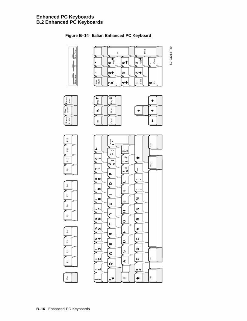
Enhanced PC KeyboardsB.2 Enhanced PC Keyboards
Figure B–14 Italian Enhanced PC Keyboard
Es
cF
1F
2F
3F
4F
5F
6F
7F
8F
9F
10
F1
1F
12
Sta
mp
Blo
cS
corr
R S
ist
Inte
rr
Pa
usa
Pa
g
_
Pa
gF
ine
Ins
Ca
nc
Blo
cN
um 78
9
45
6 32
1 0
+ Invi
o
*/
.
Ins
Pa
g
Pa
gF
ine
Ca
nc
Ital
y2
3
LJ-
03
21
3-T
I0
Blo
c N
um
Blo
c S
corr
_
12
34
56
78
90
!
#
%&
()
a
-
=
ZX
CV
BN
AS
DF
GH
JK
L
IO
PT
YU
WE
R
M
Q
?/
.,
"\
]
]:
;
Ctr
lC
trl
SS
|^
$
* +In
vio
ee
ua
i
c o
> <
Alt
Alt
Gr
B–16 Enhanced PC Keyboards

Enhanced PC KeyboardsB.2 Enhanced PC Keyboards
Figure B–15 Latin American Enhanced PC Keyboard
Re
Pag
Inic
ioIn
sert
Es
cF
1F
2F
3F
4F
5F
6F
7F
8F
9F
10
F1
1F
12
Imp
rP
an
tB
loq
De
spl
Pe
tSis
Inte
r
Pa
usa
Fin
Su
pr
Inic
ioR
eP
ag
_/
Fin
Ins
Su
pr
Blo
qN
um 78
9
45
6 32
1 0
+ Intr
o
*
Av
Pag
AvP
ag
Sp
anis
h,
Nat
ion
al (
Sp
anis
h I
I)2
7
LJ-
03
21
6-T
I0
Blo
q N
um
Blo
q M
ayu
sB
loq
De
spl
_
12
34
56
78
90
!$
%
-Z
XC
VB
N
AS
DF
GH
JK
L
IO
TY
UW
ER
M
Q
.,
:;
"
Ma
yu
s
Co
ntr
ol
&(
)=
/
?
Blo
q
#
a
> <
Co
ntr
ol
Alt
Alt
Gr
~
P
N] }
?
}]
*
.
Enhanced PC Keyboards B–17

Enhanced PC KeyboardsB.2 Enhanced PC Keyboards
Figure B–16 Norwegian Enhanced PC Keyboard
Pa
ge
Up
Ho
me
Inse
rt
Es
cF
1F
2F
3F
4F
5F
6F
7F
8F
9F
10
F1
1F
12
Pri
nt
Scr
ee
nS
cro
llL
ock
Sy
sR
qB
rea
k
Pa
use
Pa
ge
Do
wn
End
De
lete
Ho
me
Pg
Up
_
Pg
Dn
En
d
Ins
De
l
Num
Lo
ck
78
9
45
6 32
1 0’
+ En
ter
*/
No
rway
24
LJ-
03
21
4-T
I0
Nu
m L
ock
Ca
ps
Lo
ckS
cro
ll L
ock
_
12
34
56
78
!#
%&
(a
-Z
XC
VB
N
AS
DF
GH
JK
L
TY
UW
ER
M
Q
/
.,
"
]
:;
Ctr
lC
trl
S
S |$
{
*O
> <
Alt
Gr
Alt
Ca
ps
Lo
ck
90
)=
IO
P
?\
]
^
}
A
+
~..
B–18 Enhanced PC Keyboards
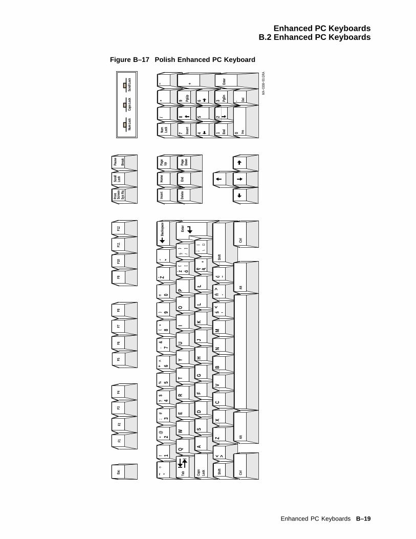
Enhanced PC KeyboardsB.2 Enhanced PC Keyboards
Figure B–17 Polish Enhanced PC Keyboard
Ctrl
Lock
Caps
Alt
Alt
Ctrl
Num
Lock
Caps
Lock
Scro
ll Loc
k
Inse
rt
Delet
e
Hom
e
End
Page
Up Page
Down
Scre
enSc
roll
Lock
Paus
e
Sys R
qBr
eak
F9F1
1F1
2F1
0F5
F6F7
F8F2
F3F4
F1
Back
spac
e
Esc
Enter
Shift
Shift
Tab~
°1
/!
*2
−"
3
@
4
#
5
:
6
3
7
$
8
?
9
45
+
%
.
6
Del
^
Inse
rt
+
PgUp
7
PgDn
&_
8*
(
.
9)
Enter
0=Z.
Ins
Y
End
Q
2
W
1
E
0
R
Num
T
Lock
UI
OP
ó{ [
z} ]
/§
AS
DF
GH
JK
LL
e a;
¤\
|
XC
BN
MV
Z<
,s>
.n><
−c
MA−
0308
−93.
GRA
´
Enhanced PC Keyboards B–19

Enhanced PC KeyboardsB.2 Enhanced PC Keyboards
Figure B–18 Portuguese Enhanced PC Keyboard
Pa
ge
Up
Ho
me
Inse
rt
Es
cF
1F
2F
3F
4F
5F
6F
7F
8F
9F
10
F1
1F
12
Pri
nt
Scr
ee
nS
cro
llL
ock
Sy
sR
qB
rea
k
Pa
use
Pa
ge
Do
wn
End
De
lete
Ho
me
Pg
Up
_
Pg
Dn
En
d
Ins
De
l
Num
Lo
ck
78
9
45
6 32
1 0
+ En
ter
*/
.
Po
rtu
gal
25
LJ-
03
21
5-T
I0
Nu
m L
ock
Ca
ps
Lo
ckS
cro
ll L
ock
_
12
34
56
78
90
!#
%&
()
a
-
=
ZX
CV
BN
AS
DF
GH
JK
IO
TY
UW
ER
M
Q
?/
.,
"\
]
]
:;
Ctr
l
S
S
|$
}{
Ctr
l
> <
Alt
Alt
Gr
Ca
ps
Lo
ck
~L
P
^
* +
Ca o..
En
ter
>>
<<
B–20 Enhanced PC Keyboards

Enhanced PC KeyboardsB.2 Enhanced PC Keyboards
Figure B–19 Romanian Enhanced PC Keyboard
[ ]1
/*
−
3
45
6
78
9
+
.
Del
Inse
rtPg
Up
PgDn
.
Enter
Ctrl
Lock
Caps
Alt
Alt
Ins
Ctrl
Num
Lock
Caps
Lock
Scro
ll Loc
k
End
21 0Nu
mLo
ck
Inse
rt
Delet
e
Hom
e
End
Page
Up Page
Down
F9F1
1F1
2F1
0F5
F6F7
F8F2
F3F4
F1Es
c
Shift
Tab
Back
spac
e
Enter
Scre
en
Shift
Scro
llLo
ckPa
use
Sys R
qBr
eak
7/) 9
*
ER
TZ
UI
OP
Q\
W|
A÷
×I
AH
JS
dD
ÐF
[G
]K
lL
L$
ST
A
<>
ß
Y>
X#
C&
V@
B{
N}
M§
,;<
: .>
−_
MA−
0301
−93.
GRA
,¸
+?..
0=’’
( 8.
& 6% 5
4¤# 3
^2"
! 1~
Enhanced PC Keyboards B–21
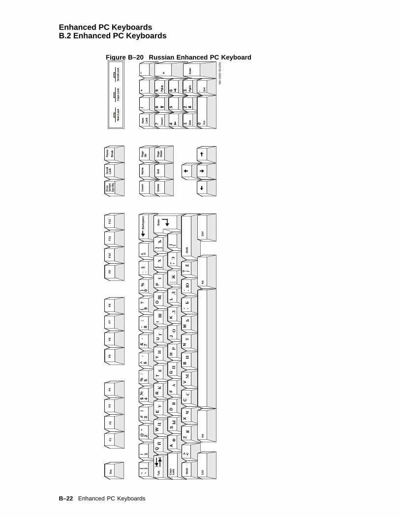
Enhanced PC KeyboardsB.2 Enhanced PC Keyboards
Figure B–20 Russian Enhanced PC Keyboard
1/
*−
3
45
6
78
9
+
.
Del
Inse
rtP
gUp
PgD
n
.
Ent
er
Ctr
l
Lock
Cap
s
Alt
Alt
Ins
Ctr
l
Num
Loc
kC
aps
Lock
Scr
oll L
ock
End
21 0N
umLo
ck
Inse
rt
Del
ete
Hom
e
End
Pag
eU
p
Pag
eD
own
F9
F11
F12
F10
F5
F6
F7
F8
F2
F3
F4
F1
Esc
Shi
ft
Tab
Bac
kspa
ce
Ent
er
Prin
tS
cree
n
Shi
ft
Scr
oll
Lock
Pau
se
Sys
Rq
Bre
ak
12
34
56
78
90
~!
@#
$%
^&
*(
)−
+ =( )
"/
№:
’.
;?
%§
_
QW
ER
TU
IO
PY
{ [} ]
ЙЦ
УК
ЕН
ГШ
ЩЗ
ХЪ
AS
DF
GH
JK
L: ;
"| \
ФЫ
ВА
ПР
ОЛ
ДЖ
Э
ZX
CV
BN
M,
.? /
<>Я
ЧС
МИ
ТЬ
БЮ
Ё,
.
MA
−030
5−93
.GR
A
B–22 Enhanced PC Keyboards

Enhanced PC KeyboardsB.2 Enhanced PC Keyboards
Figure B–21 SCS Enhanced PC Keyboard
1/
*−
3
45
6
78
9
+
Del
Inse
rtPg
Up
PgDn
.
Ente
r
Ctrl
Lock
Caps
Alt
Alt
Ins
Ctrl
Num
Loc
kCa
ps L
ock
Scro
ll Loc
k
End
21 0Nu
m
Lock
Inse
rt
Dele
te
Hom
e
End
Page
Up Page
Down
F9F1
1F1
2F1
0F5
F6F7
F8F2
F3F4
F1Es
c
Shift
Back
spac
e
Ente
r
Prin
tSc
reen
Shift
Scro
llLo
ckPa
use
Sys
RqBr
eak
! 1"
@2
# 3$ 4
% 5&
^6
7&
( 8*
)(
9=
)0
_? /
−+
* +=
QW
ER
TY
UI
OP
{ [
} ]S
D−
AS
DF
GH
JK
L"
\|;:
ZC’
C
> <Z
XC
VB
NM
< ,>
: ..
_ −? /
;:
Tab~
MA−
0307
−93.
GR
A
Enhanced PC Keyboards B–23
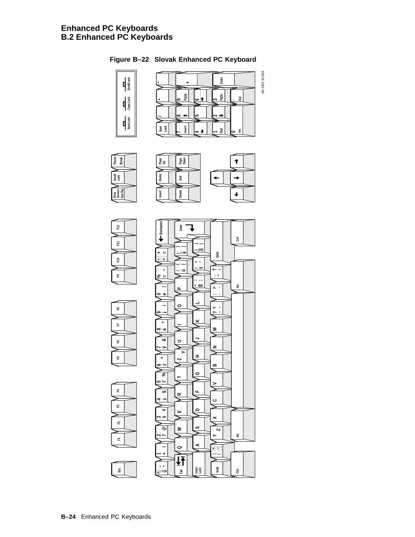
Enhanced PC KeyboardsB.2 Enhanced PC Keyboards
Figure B–22 Slovak Enhanced PC Keyboard
1/
*−
3
45
6
78
9
+
.
Del
Inse
rtPg
Up
PgDn
.
Enter
Ctrl
Lock
Caps
Alt
Alt
Ins
Ctrl
Num
Lock
Caps
Lock
Scro
ll Loc
k
End
21 0Nu
mLo
ck
Inse
rt
Delet
e
Hom
e
End
Page
Up Page
Down
F9F1
1F1
2F1
0F5
F6F7
F8F2
F3F4
F1Es
c
Shift
Tab
Back
spac
e
Enter
Scre
en
Shift
Scro
llLo
ckPa
use
Sys R
qBr
eak
QW
ER
TU
IO
P{
}u
(Z
][
aY
../
A
’
SD
FG
HJ
KL
"§
;\
:!
|o
")
X
n
CV
BN
M\
? ,< ,
|>
:_
.−
Y?
./
Z
MA−
0302
−93.
GRA
+!
~@
l ’#
sb
$c
%t’
^z
&y’
*a’
( e’
)=
−+ =
´2
%_
71
34
56
80
9u
..
B–24 Enhanced PC Keyboards
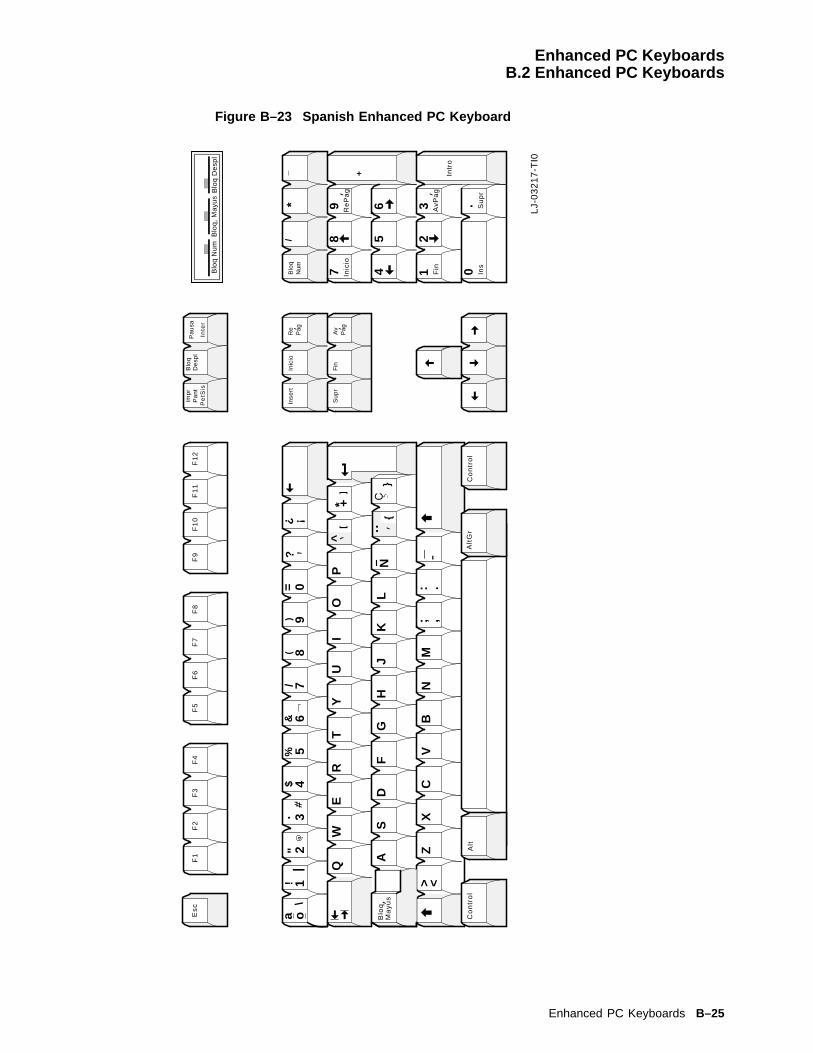
Enhanced PC KeyboardsB.2 Enhanced PC Keyboards
Figure B–23 Spanish Enhanced PC Keyboard
Re
Pag
Inic
ioIn
sert
Es
cF
1F
2F
3F
4F
5F
6F
7F
8F
9F
10
F1
1F
12
Imp
rP
an
tB
loq
De
spl
Pe
tSis
Inte
r
Pa
usa
Fin
Su
pr
Inic
ioR
eP
ag
_/
Fin
Ins
Su
pr
Blo
qN
um 78
9
45
6 32
1 0
+ Intr
o
*
Av
Pag
AvP
ag
Inte
rnat
ion
al S
pan
ish
26
LJ-
03
21
7-T
I0
Blo
q N
um
Blo
q,
Ma
yus
Blo
q D
esp
l
_
12
34
56
78
90
!$
%
-Z
XC
VB
N
AS
DF
GH
JK
L
IO
TY
UW
ER
M
Q
.,
:;
"
Ma
yu
s
Co
ntr
ol
&(
)=
?/
a o
?
Blo
q
#a
\
}
|
> <
Co
ntr
ol
Alt
Alt
Gr
^* +
P
N..
]
]
} }
..
.
Enhanced PC Keyboards B–25
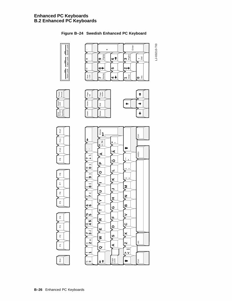
Enhanced PC KeyboardsB.2 Enhanced PC Keyboards
Figure B–24 Swedish Enhanced PC Keyboard
Pa
ge
Up
Ho
me
Inse
rt
Es
cF
1F
2F
3F
4F
5F
6F
7F
8F
9F
10
F1
1F
12
Pri
nt
Scr
ee
nS
cro
llL
ock
Sy
sR
qB
rea
k
Pa
use
Pa
ge
Do
wn
End
De
lete
Ho
me
Pg
Up
_
Pg
Dn
En
d
Ins
De
l
Num
Lo
ck
78
9
45
6 32
1 0’
+ En
ter
Sw
eden
/Fin
lan
d2
0
LJ-
03
21
0-T
I0
Nu
m L
ock
Ca
ps
Lo
ckS
cro
ll L
ock
_
12
34
56
78
90
!#
%&
()
a
-
=
ZX
CV
BN
AS
DF
GH
JK
L
IO
PT
YU
WE
R
M
Q
?/
.,
"\
]
]
:;
Ctr
l
S
S
$}
{2
1
O..
+
|> <
Alt
Gr
Ca
ps
Lo
ck
*A..
AE
nte
r..
~
Alt
Ctr
l
x
B–26 Enhanced PC Keyboards
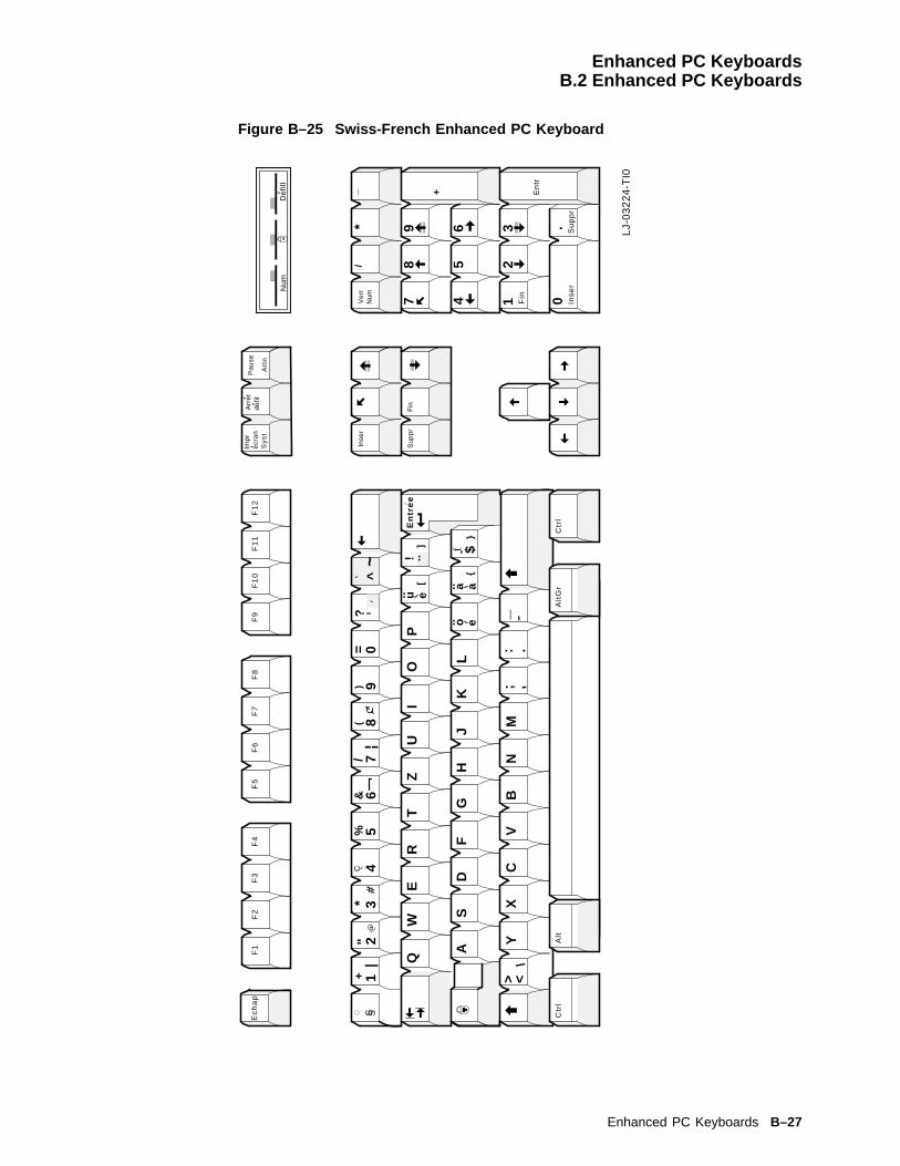
Enhanced PC KeyboardsB.2 Enhanced PC Keyboards
Figure B–25 Swiss-French Enhanced PC Keyboard
Inse
r
Ec
ha
pF
1F
2F
3F
4F
5F
6F
7F
8F
9F
10
F1
1F
12
Imp
re
cra
nA
rre
td
efil
Sy
st
Att
n
Pa
use
Fin
Su
pp
r
_/
Fin
Inse
r
Ve
rrN
um 78
9
45
6 32
1 0
+ En
tr
* Su
pp
r
Fre
nch
21
LJ-
03
22
4-T
I0
Num
De
fill
12
34
56
78
+#
%&
*(
a
-Y
XC
VB
N
AS
DF
GH
J
IT
ZU
WE
R
M
Q
/
.,
"
:;
Ctr
l
|S
S
|
\
Ctr
l
> <
Alt
Alt
Gr
_
90
)=
KL
OP
?
]
]
! $}
{
..~^
eu..
eo..
aa..
.
En
tre
e
Enhanced PC Keyboards B–27

Enhanced PC KeyboardsB.2 Enhanced PC Keyboards
Figure B–26 Swiss-German Enhanced PC Keyboard
Bild
Po
s 1
Ein
fg
Es
cF
1F
2F
3F
4F
5F
6F
7F
8F
9F
10
F1
1F
12
Dru
ckR
olle
n
S-A
bf
Un
tbr
Pa
use
En
de
En
tf
Po
s 1
Bild
_
Bild
En
de
Ein
fgE
ntf
Num 7
89
45
6 32
1 0
+ En
ter
Bild
x
Sw
iss-
Ger
man
22
LJ-
03
22
0-T
I0
Num
Ro
llen
12
34
56
78
+#
%&
*(
a
-Y
XC
VB
N
AS
DF
GH
J
IT
ZU
WE
R
M
Q
/
.,
"
:;
Str
g
|S
S
|
\
Str
g
> <
Alt
Alt
Gr
Ca
ps
Lo
ck
_
90
)=
KL
OP
?
]
]
! $}
{
e u..
e o..a a..
..~^
.
B–28 Enhanced PC Keyboards
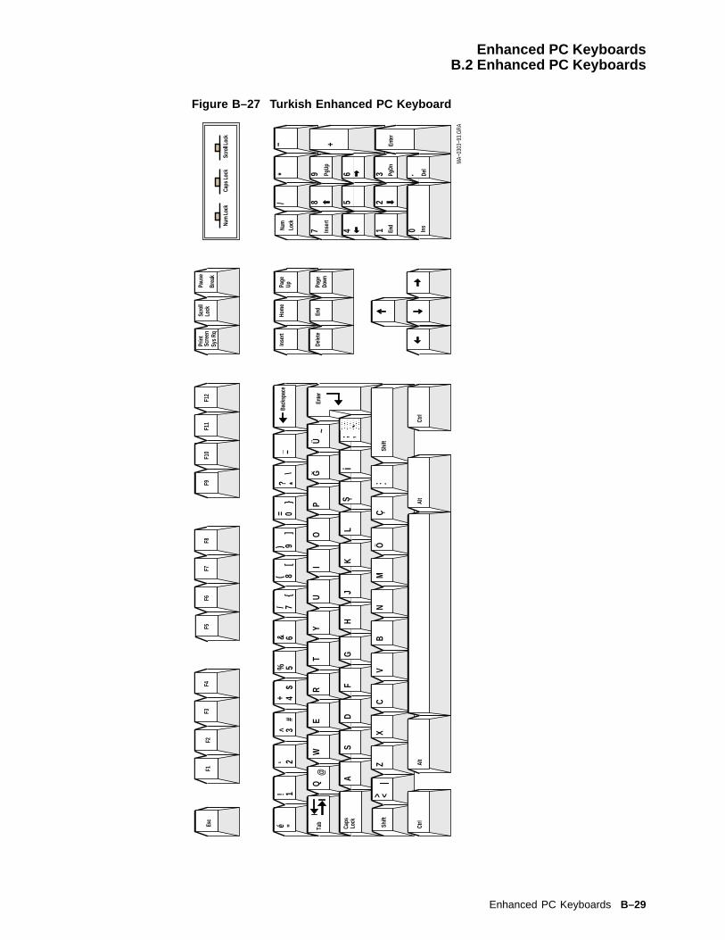
Enhanced PC KeyboardsB.2 Enhanced PC Keyboards
Figure B–27 Turkish Enhanced PC Keyboard
1/
*−
3
45
6
78
9
+
.
Del
Inse
rtPg
Up
PgDn
.
Enter
Ctrl
Lock
Caps
Alt
Alt
Ins
Ctrl
Num
Lock
Caps
Lock
Scro
ll Loc
k
End
21 0Nu
mLo
ck
Inse
rt
Delet
e
Hom
e
End
Page
Up Page
Down
F9F1
1F1
2F1
0F5
F6F7
F8F2
F3F4
F1Es
c
Shift
Tab
Back
spac
e
Enter
Scre
en
Shift
Scro
llLo
ckPa
use
Sys R
qBr
eak
−_"é
1!$
5%#
6&{
[]
*}
?\
WE
RT
UI
OP
Y~
GÜ
Q@ A
SD
FG
HJ
KL
; ,S ,
i
ZX
CV
BN
M> <
|.:
ÖÇ
3^+ 4
/ 78(
9)0=
MA−
0303
−93.
GRA
‘ 2
Enhanced PC Keyboards B–29


CASCII Keycodes and Local Functions
C.1 PC KeyboardTable C–1 through Table C–11 list the keycodes sent by individual keys in each mode for the PCkeyboard. The Alt key does not effect the keycode sent unless specified.
Table C–1 WYSE and TVI Modes Function Keys for PC Keyboard
Key Unmodified Shift Ctrl Shift/Ctrl
F1 SOH @ CR SOH ‘ CR 80 (Hex) 90 (Hex)
F2 SOH A CR SOH a CR 81 (Hex) 91 (Hex)
F3 SOH B CR SOH b CR 82 (Hex) 92 (Hex)
F4 SOH C CR SOH c CR 83 (Hex) 93 (Hex)
F5 SOH D CR SOH d CR 84 (Hex) 94 (Hex)
F6 SOH E CR SOH e CR 85 (Hex) 95 (Hex)
F7 SOH F CR SOH f CR 86 (Hex) 96 (Hex)
F8 SOH G CR SOH g CR 87 (Hex) 97 (Hex)
F9 SOH H CR SOH h CR 88 (Hex) 98 (Hex)
F10 SOH I CR SOH i CR 89 (Hex) 99 (Hex)
F11 SOH J CR SOH j CR 8A (Hex) 9A (Hex)
F12 SOH K CR SOH k CR 8B (Hex) 9B (Hex)
Print Screen ESC P ESC P Toggle Autoprint Toggle Autoprint
Scroll Lock Hold Hold Hold Hold
Pause Disconnect SendAnswerback
Break Toggle Block Mode
Table C–2 WYSE and TVI Modes Function Keys for PC Keyboard
Key Alt Alt/Shift Alt/Ctrl Alt/Shift/Ctrl
Print Screen Set-Up Soft Reset ESC P Toggle Autoprint (Note)
Pause SOH N CR SOH n CR Break 9E (Hex) (Note)
ASCII Keycodes and Local Functions C–1

ASCII Keycodes and Local FunctionsC.1 PC Keyboard
Table C–3 WYSE and TVI Modes Editing Keys for PC Keyboard
Key Unmodified Shift Ctrl Shift/Ctrl
Insert ESC q ESC r Toggle Insert Mode Toggle Insert Mode
Home 1E (Hex) ESC { Toggle Auto Panning Home Cursor and Clear Page
Page Up ESC J ESC J Display Previous Page Display Previous Page
Delete ESC W ESC R ESC W ESC R
End ESC T ESC Y ESC T Screen Saver
Page Down ESC K ESC K Display Next Page Display Next Page
Table C–4 WYSE and TVI Modes Cursor Keys on PC Keyboard
Key Unmodified Shift Ctrl Shift/Ctrl
* VT VT† Roll Active Page Up Speed Scrolling Rate
+ LF‡ LF Roll Active Page Down Slow Scrolling Rate
) FF FF Change Status Line Type Change Status Line Type
( BS BS BS BS
†"ESC j" for TVI 925 and TVI 950 emulations.‡"16 (Hex)" for TVI 925 and TVI 950 emulations.
Table C–5 WYSE and TVI Modes Numeric Keys for PC Keyboard, NumLock = Off
Key Unmodified Shift Ctrl Shift/Ctrl
0 ESC r ESC q Display Page 0 ESC q
1 ESC T ESC Y Display Page 1 Toggle Monitor Mode
2 LF1 LF Display Page 2 LF
3 ESC K ESC K Display Page 3 ESC K
4 BS BS Display Page 4 BS
5 5 5 Display Page 5 5
6 FF FF FF 6
7 1E (Hex) ESC { 1E (Hex) ESC {
8 VT VT2 VT VT
9 ESC J ESC J ESC J ESC J
/ / / / /
* * * * *
- - - Raise Split Line Toggle Split Screen Mode
+ + + + +
. 7F (Hex) 7F (Hex) 7F (Hex) Print Page
Enter CR Toggle Keyclick CR CR
1"16 (Hex)" for TVI 925 and TVI 950 emulations.2"ESC j" for TVI 925 and TVI 950 emulations.
C–2 ASCII Keycodes and Local Functions
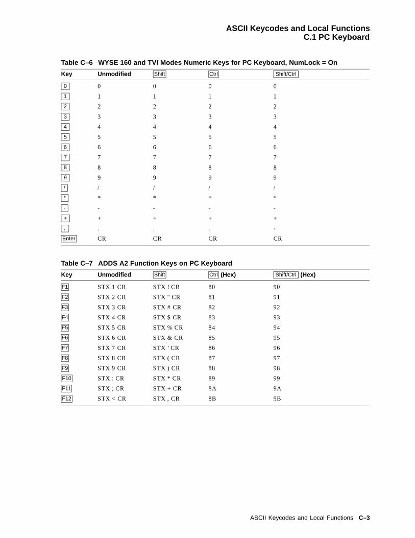
ASCII Keycodes and Local FunctionsC.1 PC Keyboard
Table C–6 WYSE 160 and TVI Modes Numeric Keys for PC Keyboard, NumLock = On
Key Unmodified Shift Ctrl Shift/Ctrl
0 0 0 0 0
1 1 1 1 1
2 2 2 2 2
3 3 3 3 3
4 4 4 4 4
5 5 5 5 5
6 6 6 6 6
7 7 7 7 7
8 8 8 8 8
9 9 9 9 9
/ / / / /
* * * * *
- - - - -
+ + + + +
. . . . -
Enter CR CR CR CR
Table C–7 ADDS A2 Function Keys on PC Keyboard
Key Unmodified Shift Ctrl (Hex) Shift/Ctrl (Hex)
F1 STX 1 CR STX ! CR 80 90
F2 STX 2 CR STX " CR 81 91
F3 STX 3 CR STX # CR 82 92
F4 STX 4 CR STX $ CR 83 93
F5 STX 5 CR STX % CR 84 94
F6 STX 6 CR STX & CR 85 95
F7 STX 7 CR STX ’ CR 86 96
F8 STX 8 CR STX ( CR 87 97
F9 STX 9 CR STX ) CR 88 98
F10 STX : CR STX * CR 89 99
F11 STX ; CR STX + CR 8A 9A
F12 STX < CR STX , CR 8B 9B
ASCII Keycodes and Local Functions C–3

ASCII Keycodes and Local FunctionsC.1 PC Keyboard
Table C–8 ADDS A2 Editing Keys on PC Keyboard
Key Unmodified Shift Ctrl Shift/Ctrl
Insert ESC q ESC r Toggle Insert Mode Toggle Insert Mode
Home SOH SOH Toggle AutoPanning
Home Cursor and Clear Page
Page Up ESC J ESC J Display PreviousPage
Display Previous Page
Delete ESC W ESC l ESC W ESC I
End ESC K ESC k ESC K Screen Saver
Page Down ESC J ESC J Display Next Page Display to Next Page
Table C–9 ADDS A2 Cursor Keys on PC Keyboard
Key Unmodified Shift Ctrl Shift/Ctrl
* 1A (Hex) 1A (Hex) Roll Active Page Up Speed Scrolling Rate
+ LF LF Roll Active Page Down Speed Scrolling Rate
) ACK ACK Change Status LineType
Change Status Line Type
( 15 (Hex) 15 (Hex) 15 (Hex) 15 (Hex)
Table C–10 ADDS A2 Mode Numeric Keypad Keys on PC Keyboard; NumLock = Off
Key Unmodified Shift Ctrl Shift/Ctrl
0 ESC r ESC q Display Page 0 ESC q
1 ESC K ESC K Display Page 1 Toggle Monitor Mode
2 LF LF Display Page 2 LF
3 ESC J ESC J Display Page 3 ESC J
4 15(Hex) 15(Hex) Display Page 4 15(Hex)
5 5 5 Display Page 5 5
6 ACK ACK ACK 6
7 SOH SOH SOH SOH
8 1A(Hex) 1A(Hex) 1A(Hex) 1A(Hex)
9 ESC J ESC J ESC J ESC J
/ / / / /
* * * * *
- - - Raise Split Line Toggle Split Screen Mode
+ + + + +
. 7F (Hex) 7F (Hex) 7F (Hex) Print Page
Enter CR Toggle Keyclick CR CR
C–4 ASCII Keycodes and Local Functions
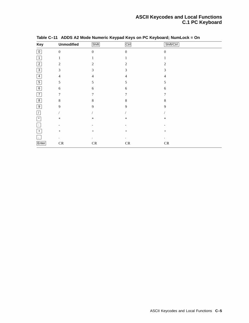
ASCII Keycodes and Local FunctionsC.1 PC Keyboard
Table C–11 ADDS A2 Mode Numeric Keypad Keys on PC Keyboard; NumLock = On
Key Unmodified Shift Ctrl Shift/Ctrl
0 0 0 0 0
1 1 1 1 1
2 2 2 2 2
3 3 3 3 3
4 4 4 4 4
5 5 5 5 5
6 6 6 6 6
7 7 7 7 7
8 8 8 8 8
9 9 9 9 9
/ / / / /
* * * * *
- - - - -
+ + + + +
. . . . .
Enter CR CR CR CR
ASCII Keycodes and Local Functions C–5

ASCII Keycodes and Local FunctionsC.2 DEC VT Keyboard
C.2 DEC VT KeyboardTable C–12 through Table C–19 list the keycodes sent by individual keys in each mode for VTkeyboards. The Alt key does not effect the keycode sent unless specified.
Table C–12 WYSE and TVI Modes Function Keys for DEC VT Keyboard
Key Unmodified Shift Ctrl Shift/Ctrl
F1 Toggle HoldScreen
Toggle HoldScreen
Toggle Hold Screen Toggle Hold Screen
F2 ESC P ESC P Toggle AutoPrint Toggle AutoPrint
F3 Setup Soft Reset 82 (Hex) 92 (Hex)
F4 Toggle BlockMode
ESC 7 Toggle Block Mode ESC 7
F5 Break Disconnect Send Answerback Toggle Block Mode
F6 SOH E CR SOH e CR 85 (Hex) 95 (Hex)
F7 SOH F CR SOH f CR 86 (Hex) 96 (Hex)
F8 SOH G CR SOH g CR 87 (Hex) 97 (Hex)
F9 SOH H CR SOH h CR 88 (Hex) 98 (Hex)
F10 SOH I CR SOH i CR 89 (Hex) 99 (Hex)
F11 SOH J CR SOH j CR 8A (Hex) 9A (Hex)
F12 SOH K CR SOH k CR 8B (Hex) 9B (Hex)
F13 SOH L CR SOH l CR 8C (Hex) 9C (Hex)
F14 SOH M CR SOH m CR 8D (Hex) 9D (Hex)
F15 SOH N CR SOH n CR 8E (Hex) 9E (Hex)
F16 SOH O CR SOH o CR 8F (Hex) 9F (Hex)
F17 SOH P CR SOH p CR SOH P CR SOH p CR
F18 SOH Q CR SOH q CR SOH Q CR SOH q CR
F19 SOH R CR SOH r CR SOH R CR SOH r CR
F20 SOH S CR SOH s CR SOH S CR SOH s CR
Table C–13 WYSE and TVI Modes Editing Keys on DEC VT Keyboard
Key Unmodified Shift Ctrl Shift/Ctrl
Find n/a n/a n/a n/a
Insert ESC Q ESC E ESC Q ESC E
Remove 7F (Hex) 7F (hex) 7F (Hex) 7F (Hex)
Select n/a n/a n/a n/a
Prev ESC J ESC J Move to Previous Page Move to Previous Page
Next ESC K ESC K Move to Next Page Move to Next Page
C–6 ASCII Keycodes and Local Functions
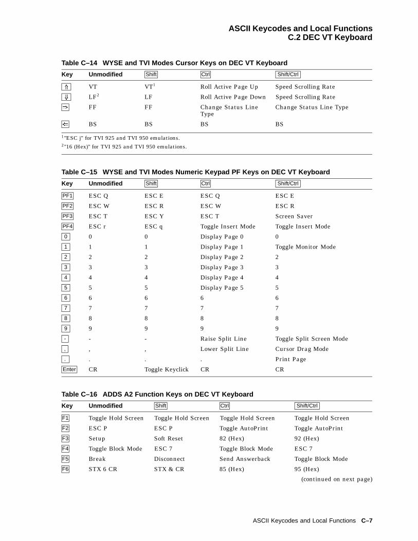
ASCII Keycodes and Local FunctionsC.2 DEC VT Keyboard
Table C–14 WYSE and TVI Modes Cursor Keys on DEC VT Keyboard
Key Unmodified Shift Ctrl Shift/Ctrl
* VT VT1 Roll Active Page Up Speed Scrolling Rate
+ LF2 LF Roll Active Page Down Speed Scrolling Rate
) FF FF Change Status LineType
Change Status Line Type
( BS BS BS BS
1"ESC j" for TVI 925 and TVI 950 emulations.2"16 (Hex)" for TVI 925 and TVI 950 emulations.
Table C–15 WYSE and TVI Modes Numeric Keypad PF Keys on DEC VT Keyboard
Key Unmodified Shift Ctrl Shift/Ctrl
PF1 ESC Q ESC E ESC Q ESC E
PF2 ESC W ESC R ESC W ESC R
PF3 ESC T ESC Y ESC T Screen Saver
PF4 ESC r ESC q Toggle Insert Mode Toggle Insert Mode
0 0 0 Display Page 0 0
1 1 1 Display Page 1 Toggle Monitor Mode
2 2 2 Display Page 2 2
3 3 3 Display Page 3 3
4 4 4 Display Page 4 4
5 5 5 Display Page 5 5
6 6 6 6 6
7 7 7 7 7
8 8 8 8 8
9 9 9 9 9
- - - Raise Split Line Toggle Split Screen Mode
, , , Lower Split Line Cursor Drag Mode
. . . . Print Page
Enter CR Toggle Keyclick CR CR
Table C–16 ADDS A2 Function Keys on DEC VT Keyboard
Key Unmodified Shift Ctrl Shift/Ctrl
F1 Toggle Hold Screen Toggle Hold Screen Toggle Hold Screen Toggle Hold Screen
F2 ESC P ESC P Toggle AutoPrint Toggle AutoPrint
F3 Setup Soft Reset 82 (Hex) 92 (Hex)
F4 Toggle Block Mode ESC 7 Toggle Block Mode ESC 7
F5 Break Disconnect Send Answerback Toggle Block Mode
F6 STX 6 CR STX & CR 85 (Hex) 95 (Hex)
(continued on next page)
ASCII Keycodes and Local Functions C–7

ASCII Keycodes and Local FunctionsC.2 DEC VT Keyboard
Table C–16 (Cont.) ADDS A2 Function Keys on DEC VT Keyboard
Key Unmodified Shift Ctrl Shift/Ctrl
F7 STX 7 CR STX ’ CR 86 (Hex) 96 (Hex)
F8 STX 8 CR STX ( CR 87 (Hex) 97 (Hex)
F9 STX 9 CR STX ) CR 88 (Hex) 98 (Hex)
F10 STX : CR STX * CR 89 (Hex) 99 (Hex)
F11 STX ; CR STX + CR 8A (Hex) 9A (Hex)
F12 STX < CR STX , CR 8B (Hex) 9B (Hex)
F13 STX = CR STX - CR 8C (Hex) 9C (Hex)
F14 STX > CR STX . CR 8D (Hex) 9D (Hex)
F15 STX ? CR STX / CR 8E (Hex) 9E (Hex)
F16 STX @ CR STX 0 CR 8F (Hex) 9F (Hex)
F17 STX A CR STX 1 CR STX A CR STX 1 CR
F18 STX B CR STX 2 CR STX B CR STX 2 CR
F19 STX C CR STX 3 CR STX C CR STX 3 CR
F20 STX D CR STX 4 CR STX D CR STX 4 CR
Table C–17 ADDS A2 Editing Keys on DEC VT Keyboard
Key Unmodified Shift Ctrl Shift/Ctrl
Find n/a n/a n/a n/a
Insert ESC Q ESC M ESC Q ESC M
Remove 7F (Hex) 7F (Hex) 7F (Hex) 7F (Hex)
Select n/a n/a n/a n/a
Prev ESC J ESC J Move to Previous Page Move to Previous Page
Next ESC J ESC J Move to Next Page Move to Next Page
Table C–18 ADDS A2 Cursor Keys on DEC VT Keyboard
Key Unmodified Shift Ctrl Shift/Ctrl
* 1A (Hex) 1A (Hex) Roll Active Page UP Speed Scrolling Rate
+ LF LF Roll Active Page Down Speed Scrolling Rate
) ACK ACK Change Status LineType
Change Status Line Type
( 15 (Hex) 15 (Hex) 15 (Hex) 15 (Hex)
Table C–19 ADDS A2 Numeric Keypad PFKeys on DEC VT Keyboard
Key Unmodified Shift Ctrl Shift/Ctrl
PF1 ESC Q ESC M ESC Q ESC M
PF2 ESC W ESC l ESC W ESC l
(continued on next page)
C–8 ASCII Keycodes and Local Functions

ASCII Keycodes and Local FunctionsC.2 DEC VT Keyboard
Table C–19 (Cont.) ADDS A2 Numeric Keypad PFKeys on DEC VT Keyboard
Key Unmodified Shift Ctrl Shift/Ctrl
PF3 ESC K ESC k ESC K Screen Saver
PF4 ESC r ESC q Toggle Insert Mode Toggle Insert Mode
0 0 0 Display Page 0 0
1 1 1 Display Page 1 Toggle Monitor Mode
2 2 2 Display Page 2 2
3 3 3 Display Page 3 3
4 4 4 Display Page 4 4
5 5 5 Display Page 5 5
6 6 6 6 6
7 7 7 7 7
8 8 8 8 8
9 9 9 9 9
- - - Raise Split Line Toggle Split Screen Mode
, , , Lower Split Line Cursor Drag Mode
. . . . Print Page
Enter CR Toggle KeyclickState
CR CR
C.3 ASCII Local FunctionsTable C–20 and Table C–21 list the local functions in ASCII code mode and PC scancode mode.In the tables, keypad is abbreviated as (kpd).
Table C–20 Local Functions in ASCII Code Mode
Function DEC VT Layout EPC Layout
±Hold Screen F1 Scroll Lock
Print page Ctrl/Shift/ . (kpd) Ctrl/Shift/ . (kpd)
Set-Up F3 Alt/Print Screen
Caps Lock/F3 Caps Lock/Print Screen
Break F5 Ctrl/Pause
Hard Reset Ctrl/F3 in Set-Up
Soft Reset Shift/F3 Alt/Shift/Print Screen
±Autoprint Mode Ctrl/F2 Ctrl/Print Screen
Ctrl/Shift/F2 Ctrl/Shift/Print Screen
Alt/Ctrl/Shift/Print Screen
Disconnect Shift/F5 Pause
Send Answerback Ctrl/F5 Shift/Pause
Display Next Page Ctrl/Next Ctrl/Page Down
(continued on next page)
ASCII Keycodes and Local Functions C–9

ASCII Keycodes and Local FunctionsC.3 ASCII Local Functions
Table C–20 (Cont.) Local Functions in ASCII Code Mode
Function DEC VT Layout EPC Layout
Shift/Ctrl/Next Ctrl/Shift/Page Down
Active Other Window Ctrl/Next or Ctrl/Prev Ctrl/Page Down orCtrl/Shift/Page Down
or Ctrl/Page Up orCtrl/Shift/Page Up
Display Prev. Page Ctrl/Prev Ctrl/Page Up
Shift/Ctrl/Prev Ctrl/Shift/Page Up
Display Page 0 Ctrl/0 (kpd) Ctrl/0 (kpd)
Display Page 1 Ctrl/1 (kpd) Ctrl/1 (kpd)
Display Page 2 Ctrl/2 (kpd) Ctrl/2 (kpd)
Display Page 3 Ctrl/3 (kpd) Ctrl/3 (kpd)
Display Page 4 Ctrl/4 (kpd) Ctrl/4 (kpd)
Display Page 5 Ctrl/5 (kpd) Ctrl/5 (kpd)
±Block Mode F4 Ctrl/Shift/Pause
Ctrl/F4
Shift/Ctrl/F5
Change Status Line Display Ctrl/) Ctrl/)
Ctrl/Shift/) Ctrl/Shift/)
±Insert Mode Ctrl/PF4 Ctrl/Insert
Ctrl/Shift/PF4 Ctrl/Shift/Insert
±Monitor Mode Ctrl/Shift/1 (kpd) Ctrl/Shift/1 (kpd)
Screen Saver Ctrl/Shift/PF3 Ctrl/Shift/End
Speed Scroll Rate Ctrl/Shift/* Ctrl/Shift/*
Slow Scroll Rate Ctrl/Shift/+ Ctrl/Shift/+
Home cursor and Clear Display Ctrl/Shift/Home
Roll Active Window Up In Page Ctrl/* Ctrl/*
Roll Active Window Down In Page Ctrl/+ Ctrl/+
±Toggle Split screen Ctrl/Shift/ - (kpd) Ctrl/Shift/ - (kpd)
Raise Split Line Ctrl/ - (kpd) Ctrl/ - (kpd)
Lower Split Line Ctrl/ , (kpd) n/a
Adjust Window to Include Cursor Ctrl/Home
±Cursor Drag Mode Ctrl/Shift/ , (kpd) n/a
±Caps Lock State Lock Caps Lock
±Num Lock State n/a NumLock
±Keyclick State Shift/Enter (kpd) Shift/Enter (kpd)
C–10 ASCII Keycodes and Local Functions
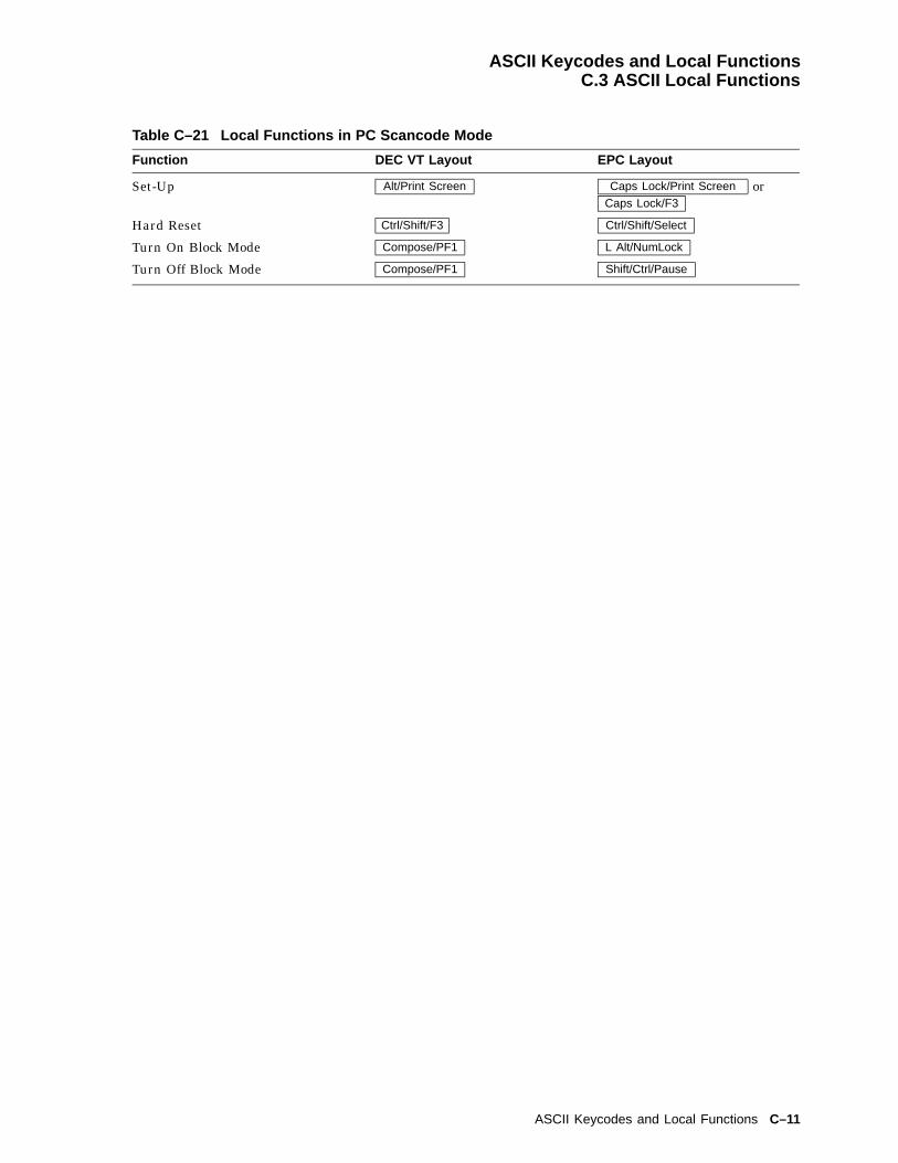
ASCII Keycodes and Local FunctionsC.3 ASCII Local Functions
Table C–21 Local Functions in PC Scancode Mode
Function DEC VT Layout EPC Layout
Set-Up Alt/Print Screen Caps Lock/Print Screen orCaps Lock/F3
Hard Reset Ctrl/Shift/F3 Ctrl/Shift/Select
Turn On Block Mode Compose/PF1 L Alt/NumLock
Turn Off Block Mode Compose/PF1 Shift/Ctrl/Pause
ASCII Keycodes and Local Functions C–11

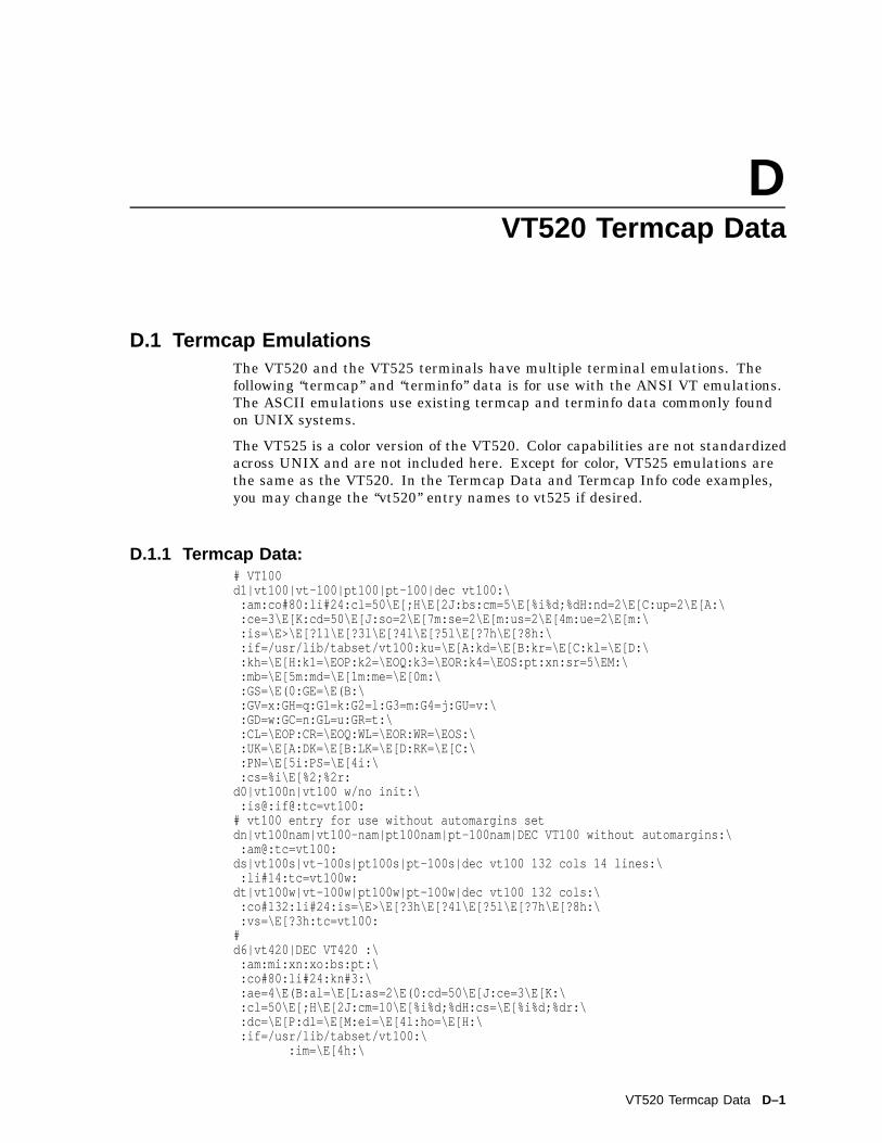
DVT520 Termcap Data
D.1 Termcap EmulationsThe VT520 and the VT525 terminals have multiple terminal emulations. Thefollowing ‘‘termcap’’ and ‘‘terminfo’’ data is for use with the ANSI VT emulations.The ASCII emulations use existing termcap and terminfo data commonly foundon UNIX systems.
The VT525 is a color version of the VT520. Color capabilities are not standardizedacross UNIX and are not included here. Except for color, VT525 emulations arethe same as the VT520. In the Termcap Data and Termcap Info code examples,you may change the ‘‘vt520’’ entry names to vt525 if desired.
D.1.1 Termcap Data:# VT100d1|vt100|vt-100|pt100|pt-100|dec vt100:\
:am:co#80:li#24:cl=50\E[;H\E[2J:bs:cm=5\E[%i%d;%dH:nd=2\E[C:up=2\E[A:\:ce=3\E[K:cd=50\E[J:so=2\E[7m:se=2\E[m:us=2\E[4m:ue=2\E[m:\:is=\E>\E[?1l\E[?3l\E[?4l\E[?5l\E[?7h\E[?8h:\:if=/usr/lib/tabset/vt100:ku=\E[A:kd=\E[B:kr=\E[C:kl=\E[D:\:kh=\E[H:k1=\EOP:k2=\EOQ:k3=\EOR:k4=\EOS:pt:xn:sr=5\EM:\:mb=\E[5m:md=\E[1m:me=\E[0m:\:GS=\E(0:GE=\E(B:\:GV=x:GH=q:G1=k:G2=l:G3=m:G4=j:GU=v:\:GD=w:GC=n:GL=u:GR=t:\:CL=\EOP:CR=\EOQ:WL=\EOR:WR=\EOS:\:UK=\E[A:DK=\E[B:LK=\E[D:RK=\E[C:\:PN=\E[5i:PS=\E[4i:\:cs=%i\E[%2;%2r:
d0|vt100n|vt100 w/no init:\:is@:if@:tc=vt100:
# vt100 entry for use without automargins setdn|vt100nam|vt100-nam|pt100nam|pt-100nam|DEC VT100 without automargins:\
:am@:tc=vt100:ds|vt100s|vt-100s|pt100s|pt-100s|dec vt100 132 cols 14 lines:\
:li#14:tc=vt100w:dt|vt100w|vt-100w|pt100w|pt-100w|dec vt100 132 cols:\
:co#132:li#24:is=\E>\E[?3h\E[?4l\E[?5l\E[?7h\E[?8h:\:vs=\E[?3h:tc=vt100:
#d6|vt420|DEC VT420 :\
:am:mi:xn:xo:bs:pt:\:co#80:li#24:kn#3:\:ae=4\E(B:al=\E[L:as=2\E(0:cd=50\E[J:ce=3\E[K:\:cl=50\E[;H\E[2J:cm=10\E[%i%d;%dH:cs=\E[%i%d;%dr:\:dc=\E[P:dl=\E[M:ei=\E[4l:ho=\E[H:\:if=/usr/lib/tabset/vt100:\
:im=\E[4h:\
VT520 Termcap Data D–1
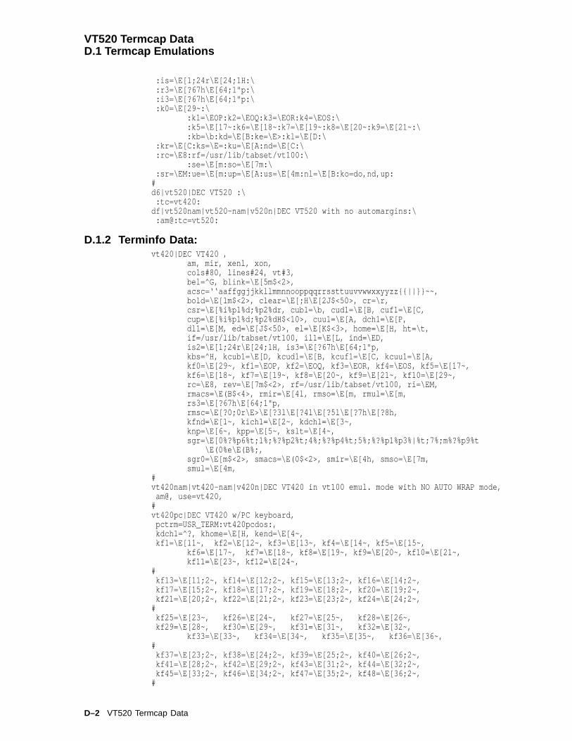
VT520 Termcap DataD.1 Termcap Emulations
:is=\E[1;24r\E[24;1H:\:r3=\E[?67h\E[64;1"p:\:i3=\E[?67h\E[64;1"p:\:k0=\E[29~:\
:k1=\EOP:k2=\EOQ:k3=\EOR:k4=\EOS:\:k5=\E[17~:k6=\E[18~:k7=\E[19~:k8=\E[20~:k9=\E[21~:\:kb=\b:kd=\E[B:ke=\E>:kl=\E[D:\
:kr=\E[C:ks=\E=:ku=\E[A:nd=\E[C:\:rc=\E8:rf=/usr/lib/tabset/vt100:\
:se=\E[m:so=\E[7m:\:sr=\EM:ue=\E[m:up=\E[A:us=\E[4m:nl=\E[B:ko=do,nd,up:
#d6|vt520|DEC VT520 :\
:tc=vt420:df|vt520nam|vt520-nam|v520n|DEC VT520 with no automargins:\
:am@:tc=vt520:
D.1.2 Terminfo Data:vt420|DEC VT420 ,
am, mir, xenl, xon,cols#80, lines#24, vt#3,bel=^G, blink=\E[5m$<2>,acsc=‘‘aaffggjjkkllmmnnooppqqrrssttuuvvwwxxyyzz{{||}}~~,bold=\E[1m$<2>, clear=\E[;H\E[2J$<50>, cr=\r,csr=\E[%i%p1%d;%p2%dr, cub1=\b, cud1=\E[B, cuf1=\E[C,cup=\E[%i%p1%d;%p2%dH$<10>, cuu1=\E[A, dch1=\E[P,dl1=\E[M, ed=\E[J$<50>, el=\E[K$<3>, home=\E[H, ht=\t,if=/usr/lib/tabset/vt100, il1=\E[L, ind=\ED,is2=\E[1;24r\E[24;1H, is3=\E[?67h\E[64;1"p,kbs=^H, kcub1=\E[D, kcud1=\E[B, kcuf1=\E[C, kcuu1=\E[A,kf0=\E[29~, kf1=\EOP, kf2=\EOQ, kf3=\EOR, kf4=\EOS, kf5=\E[17~,kf6=\E[18~, kf7=\E[19~, kf8=\E[20~, kf9=\E[21~, kf10=\E[29~,rc=\E8, rev=\E[7m$<2>, rf=/usr/lib/tabset/vt100, ri=\EM,rmacs=\E(B$<4>, rmir=\E[4l, rmso=\E[m, rmul=\E[m,rs3=\E[?67h\E[64;1"p,rmsc=\E[?0;0r\E>\E[?3l\E[?4l\E[?5l\E[?7h\E[?8h,kfnd=\E[1~, kich1=\E[2~, kdch1=\E[3~,knp=\E[6~, kpp=\E[5~, kslt=\E[4~,sgr=\E[0%?%p6%t;1%;%?%p2%t;4%;%?%p4%t;5%;%?%p1%p3%|%t;7%;m%?%p9%t
\E(0%e\E(B%;,sgr0=\E[m$<2>, smacs=\E(0$<2>, smir=\E[4h, smso=\E[7m,smul=\E[4m,
#vt420nam|vt420-nam|v420n|DEC VT420 in vt100 emul. mode with NO AUTO WRAP mode,
am@, use=vt420,#vt420pc|DEC VT420 w/PC keyboard,
pctrm=USR_TERM:vt420pcdos:,kdch1=^?, khome=\E[H, kend=\E[4~,kf1=\E[11~, kf2=\E[12~, kf3=\E[13~, kf4=\E[14~, kf5=\E[15~,
kf6=\E[17~, kf7=\E[18~, kf8=\E[19~, kf9=\E[20~, kf10=\E[21~,kf11=\E[23~, kf12=\E[24~,
#kf13=\E[11;2~, kf14=\E[12;2~, kf15=\E[13;2~, kf16=\E[14;2~,kf17=\E[15;2~, kf18=\E[17;2~, kf19=\E[18;2~, kf20=\E[19;2~,kf21=\E[20;2~, kf22=\E[21;2~, kf23=\E[23;2~, kf24=\E[24;2~,
#kf25=\E[23~, kf26=\E[24~, kf27=\E[25~, kf28=\E[26~,kf29=\E[28~, kf30=\E[29~, kf31=\E[31~, kf32=\E[32~,
kf33=\E[33~, kf34=\E[34~, kf35=\E[35~, kf36=\E[36~,#
kf37=\E[23;2~, kf38=\E[24;2~, kf39=\E[25;2~, kf40=\E[26;2~,kf41=\E[28;2~, kf42=\E[29;2~, kf43=\E[31;2~, kf44=\E[32;2~,kf45=\E[33;2~, kf46=\E[34;2~, kf47=\E[35;2~, kf48=\E[36;2~,
#
D–2 VT520 Termcap Data

VT520 Termcap DataD.1 Termcap Emulations
# DECUDK# if (key < 16) then value = key;# else if (key < 21) then value = key + 1;# else if (key < 25) then value = key + 2;# else if (key < 27) then value = key + 3;# else if (key < 30) then value = key + 4;# else value = key + 5;#
pfx=\EP1;1|%?%{16}%p1%>%t%{0}%e%{21}%p1%>%t%{1}%e%{25}%p1%>%t%{2}%e%{27}%p1%>%t%{3}%e%{30}%p1%>%t%{4}%e%{5}%;%p1%+%d/%p2%s\E\\,
use=vt420,#vt420pcdos|DEC VT420 w/PC for DOS Merge,
pctrm@,smsc=\E[?1;2r\E[34h,
rmsc=\E[?0;0r\E>\E[?3l\E[?4l\E[?5l\E[?7h\E[?8h,u0=eg,dispc=%?%p2%{19}%=%t\E\023\021%e%p2%{32}%<%t\E%p2%c%e%p2%{127}%=%t
\E\177%e%p2%c%;,sgr@,sgr0=\E[0m,lines#25,use=vt420pc,
#vt420f|DEC VT420 with VT kbd; VT400 mode; F1-F5 used as Fkeys,
kdch1=^?, khome=\E[H,kf1=\E[11~, kf2=\E[12~, kf3=\E[13~, kf4=\E[14~, kf5=\E[15~,kf6=\E[17~, kf7=\E[18~, kf8=\E[19~, kf9=\E[20~, kf10=\E[21~,kf11=\E[23~, kf12=\E[24~, kf13=\E[25~, kf14=\E[26~, kf15=\E[28~,kf16=\E[29~, kf17=\E[31~, kf18=\E[32~, kf19=\E[33~, kf20=\E[34~,lf1=\EOP, lf2=\EOQ, lf3=\EOR, lf4=\EOS,use=vt420,
## Use v420fn and v420pcn for LYRIX#vt420f-nam|v420fn|DEC VT420 no auto margins,
am@, use=vt420f,vt420pc-nam|v420pcn|DEC VT420 PC keyboard no auto margins,
am@, use=vt420pc,## vt520:##vt520|DEC VT520,
use=vt420,vt520nam|vt520-nam|v520n|DEC VT520 in vt100 emul. mode with NO AUTO WRAP mode,
use=vt420nam,vt520pc|DEC VT520 w/PC keyboard,
use=vt420pc,vt520pc-nam|v520pcn|DEC VT520 PC keyboard no auto margins,
am@, use=vt420pc,vt520pcdos|DEC VT520 w/PC for DOS Merge,
use=vt420pcdos,
VT520 Termcap Data D–3


EANSI Control Function Index
E.1 ANSI Index by Final CharacterThis index lists the ANSI host interface commands according to their finalcharacter for reference in software programs. Each command has a mnemonicreference, which is in Chapter 5.
Table E–1 ANSI Control Functions Index by Final Character
Control Function Description Reference
BEL BellBS BackspaceOSC 2 1 ; <name> Set Window Title DECSWTOSC 2 L ; <name> Set Icon Name DECSINESC # 3 Double Height Line Top DECDHLESC # 4 Double Height Line Bottom DECDHLESC # 5 Single Width Line DECSWLESC # 6 Double Width Line DECDWLESC 6 Back Index DECBIESC 7 Save Cursor DECSCESC 8 Restore Cursor DECRCESC # 8 Screen Alignment Pattern DECALNESC 9 Forward Index DECFIESC xx Display PC character xx (hex) (SCO Console) SCODPCCESC ) 1 DDD1 - Set DECRLM, DECHEBM, and
DECHCEMDDD1
ESC ) B DDD2 - ASCII to G1; reset DECRLM2 DDD2ESC ( 1 DDD3 - ASCII to G0 DDD3
A
CSI Pl A Cursor Up CUUCSI Pn a Horizontal Position Relative HPR
B
CSI Pl B Cursor Down CUD
(continued on next page)
ANSI Control Function Index E–1

ANSI Control Function IndexE.1 ANSI Index by Final Character
Table E–1 (Cont.) ANSI Control Functions Index by Final Character
Control Function Description Reference
C
CSI Pc C Cursor Forward CUFCSI c or CSI 0 c Device Attributes DA1CSI ? Psc ; PS1 ; ... Psn c Response to Device Attributes DA1CSI > c or CSI > 0 c Secondary Device Attributes DA2CSI > 64; Pv; 0 c VT520 response to Sec Device Attributes (VT
keyboard)DA2
CSI > 64; Pv; 1 c VT520 response to Sec Device Attributes (PCkeyboard)
DA2
CSI > 65; Pv; 0 c VT525 response to Sec Device Attributes (VTkeyboard)
DA2
CSI > 65; Pv; 1 c VT525 response to Sec Device Attributes (PCkeyboard)
DA2
CSI = c or CSI = 0 c Tertiary Device Attributes DA3CSI ? 1; 2 c VT100 terminal ID DECTIDCSI ? 1; 0 c VT101 terminal ID DECTIDCSI ? 6 c VT102 terminal ID DECTIDCSI ? 62; 1; 2; 7; 8 c VT220 North American DECTIDCSI ? 62; 1; 2; 7; 8; 9 c VT220 International DECTIDCSI ? 63; 1; 2; 7; 8 c VT320 North American DECTIDCSI ? 63; 1; 2; 7; 8; 9 c VT320 International DECTIDCSI ? 64; 1; 2; 6; 7; 8; 9; 15; 18; 21 c VT420 DECTIDCSI ? 65;1;2;6;7;8;9;12;23;24;46 c VT520 level 1 DECTIDCSI ? 65;1;2;6;7;8;9;12;15;18;19;21;23;24;42;44;45;46 c
VT520 level 2-4 DECTID
CSI ? 65;1;2;7;9;12;18;19;21;23;24;42;44;45;46 c
VT520 level 4 DECTID
CSI ? 65;1;2;6;7;8;9;12;15;18;19;21;22;23;24;42;44;45;46 c
VT525 level 2-4 DECTID
CSI ? 65;1;2;7;9;12;18;19;21;22;23;24;42;44;45;46 c
VT525 level 5 DECTID
ESC c Reset to Initial state RIS
D
CSI Pc D Cursor Backward CUBCSI Pn d Vertical Line Position Absolute VPAESC D Index IND
E
CSI Pn E Cursor Next Line CNLCSI Pn e Vertical Position Relative VPRESC E Next Line NEL
(continued on next page)
E–2 ANSI Control Function Index

ANSI Control Function IndexE.1 ANSI Index by Final Character
Table E–1 (Cont.) ANSI Control Functions Index by Final Character
Control Function Description Reference
F
CSI Pl ; Pc f Horizontal/Vertical Position HVPCSI Pn F Cursor Previous Line CPLESC SP F Send 7-bit C1 Control character to host S7C1T
G
CSI Pn G Cursor Horizontal Absolute CHACSI Ps g Clear Tabs TBCESC SP G Send 8-bit C1 Control character to host S8C1T
H
CSI Pl ; Pc H Cursor Position CUPCSI P1...Pn h Set Mode SMCSI ? 1 h Set Cursor Keys mode (application) DECCKMCSI 2 h Set Keyboard Action Mode KAMCSI 3 h Set Show Control Character Mode CRMCSI ? 3 h Set Column Mode (132 columns) DECCOLMCSI 4 h Set Insert Mode IRMCSI ? 4 h Set Scrolling Mode (smooth) DECSCLMCSI ? 5 h Set Screen Mode (light) DECSCNMCSI ? 6 h Set Origin Mode (in margins) DECOMCSI ? 7 h Set Autowrap Mode DECAWMCSI ? 8 h Set Autorepeat mode DECARMCSI 12 h Set Send/Receive mode (Local echo off) SRMCSI ? 18 h Set Print Form Feed Mode DECPFFCSI ? 19 h Set Printer Extent Mode DECPEXCSI 20 h Set Line Feed/New Line (NL) LNMCSI ? 25 h Set Text Cursor Enable Mode (visible) DECTCEMCSI ? 34 h Set Right-to-Left Mode DECRLMCSI ? 35 h Set Hebrew Keyboard Map Mode DECHEBMCSI ? 36 h Set Hebrew Encoding Mode to 8-bit characters DECHEMCSI ? 42 h Set National 7-bit character DECNRCMCSI ? 57 h Set N.A./Greek Selection to N.A. DECNAKBCSI ? 58 h Set (enter) ProPrinter Emulation Mode DECIPEMCSI ? 60 h Set Horizontal Cursor DECHCCMCSI ? 61 h Set Vertical Cursor Coupling DECVCCMCSI ? 64 h Set Page Cursor Coupling DECPCCMCSI ? 66 h Set Numeric Keypad Mode DECNKMCSI ? 67 h Set Backarrow key mode (BS) DECBKMCSI ? 68 h Set Data Processing Keys DECKBUMCSI ? 69 h Set Vertical Split Screen Mode DECVSSMCSI ? 73 h Set Transmit Rate Limiting DECXRLMCSI ? 81 h Set Key Position Mode DECKPM
(continued on next page)
ANSI Control Function Index E–3

ANSI Control Function IndexE.1 ANSI Index by Final Character
Table E–1 (Cont.) ANSI Control Functions Index by Final Character
Control Function Description Reference
H
CSI ? 95 h Set no clear screen on column change DECNCSMCSI ? 96 h Set Right-to-Left Copy DECRLCMCSI 97 h Set CRT Save Mode DECCRTSMCSI ? 98 h Set Auto Resize DECARSMCSI ? 99 h Set Modem Control Mode DECMCMCSI ? 100 h Set Auto Answerback Mode DECAAMCSI ? 101 h Set Conceal Answerback Message DECCANSMCSI ? 102 h Set Ignore Null Mode DECNULMCSI ? 103 h Set Half-Duplex Mode DECHDPXMCSI ? 104 h Set Enable Secondary Keyboard Language Mode DECESKMCSI ? 106 h Set Overscan Mode DECOSCNMCSI ? 108 h Set Num Lock Mode DECNUMLKCSI ? 109 h Set Caps Lock Mode DECCAPSLKCSI ? 110 h Set Keyboard LED’s Host Indicator Mode DECKLHIMCSI ? 111 h Set Framed Windows Mode DECFWMCSI ? 112 h Set Review Previous Lines DECRPLCSI ? 113 h Set Host Wake-Up Mode DECHWUMCSI ? 114 h Set Alternate Text Color Underline Mode DECATCUMCSI ? 115 h Set Alternate Text Color Blink Mode DECATCBMCSI ? 116 h Set Bold and Blink Style Mode DECBBSMCSI ? 117 h Set Erase Color Mode DECECMESC H Set Horizontal Tabs HTS
I
CSI Pn I Cursor Horizontal Forward Tab CHTCSI Ps i Media Copy MCCSI 6 i Start Printer-to-Host Session MCCSI 7 i Stop Printer-to-Host Session MCCSI ? Ps i Media Copy (DEC) MCCSI ? 8 i Stop Printer-to-Host Session MCCSI ? 9 i Start Printer-to-Host Session MCESC I Dscs Designate Character Set SCS
J
CSI Ps J Erase in Display EDCSI ? Ps J Selective Erase in Display DECSED
K
CSI Ps K Erase in Line ELCSI ? Ps K Selective Erase in Line DECSEL
(continued on next page)
E–4 ANSI Control Function Index

ANSI Control Function IndexE.1 ANSI Index by Final Character
Table E–1 (Cont.) ANSI Control Functions Index by Final Character
Control Function Description Reference
L
CSI Pn L Insert Line ILCSI P1...Pn l Reset Mode RMCSI ? 1 l Reset Cursor Keys mode (Cursor) DECCKMCSI 2 l Reset Keyboard Action Mode KAMCSI ? 2 l ANSI Mode DECANMCSI 3 l Reset Show Control Character Mode CRMCSI ? 3 l Reset Column Mode (80 columns) DECCOLMCSI 4 l Reset Insert Mode (Replace) IRMCSI ? 4 l Reset Scrolling Mode (jump) DECSCLMCSI ? 5 l Reset Screen Mode (dark) DECSCNMCSI ? 6 l Reset Origin Mode (upper left) DECOMCSI ? 7 l Reset Autowrap Mode DECAWMCSI ? 8 l Reset Autorepeat mode DECARMCSI 12 l Reset Send/Receive mode (Local echo on) SRMCSI ? 18 l Reset Print Form Feed Mode DECPFFCSI ? 19 l Reset Printer Extent Mode DECPEXCSI 20 l Reset Line Feed (LF)/New Line LNMCSI ? 25 l Reset Text Cursor Enable Mode (invisible) DECTCEMCSI ? 34 l Reset Right-to-Left Mode DECRLMCSI ? 35 l Reset Hebrew Keyboard Map Mode to N.A. DECHEBMCSI ? 36 l Reset Hebrew Encoding Mode to 7-bit characters DECHCEMCSI ? 42 l Reset Multinational 8-bit characters DECNRCMCSI ? 57 l Reset N.A./Greek Selection to Greek DECNAKBCSI ? 58 l Reset (return from) ProPrinter Emulation Mode DECIPEMCSI ? 60 l Reset Horizontal Cursor DECHCCM†CSI ? 61 l Reset Vertical Cursor Coupling DECVCCMCSI ? 64 l Reset Page Cursor Coupling DECPCCMCSI ? 66 l Reset Numeric Keypad Mode DECNKMCSI ? 67 l Reset Backarrow key mode (DEL) DECBKMCSI ? 68 l Reset to Typewriter Keys DECKBUMCSI ? 69 l Reset Vertical Split Screen Mode DECVSSMCSI ? 73 l Reset Transmit Rate Limiting DECXRLMCSI ? 81 l Reset Key Position Mode DECKPMCSI ? 95 l Reset no clear screen on column change DECNCSMCSI ? 96 l Reset Right-to-Left Copy DECRLCMCSI 97 l Reset CRT Save Mode DECCRTSMCSI ? 98 l Reset Auto Resize DECARSMCSI ? 99 l Reset Modem Control Mode DECMCMCSI ? 100 l Reset Auto Answerback Mode DECAAMCSI ? 101 l Reset Conceal Answerback Message Mode DECCANSMCSI ? 102 l Reset Ignore Null Mode DECNULMCSI ? 103 l Reset Half-Duplex Mode DECHDPXMCSI ? 104 l Reset Enable Secondary Keyboard Language Mode
to Primary keyboard mappingDECESKM
CSI ? 106 l Reset Overscan Mode DECOSCNMCSI ? 108 l Reset Num Lock Mode DECNUMLKCSI ? 109 l Reset Caps Lock Mode DECCAPSLKCSI ? 110 l Reset Keyboard LED’s Host Indicator Mode DECKLHIMCSI ? 111 l Reset Framed Windows Mode DECFWMCSI ? 112 l Reset Review Previous Lines DECRPL
(continued on next page)
ANSI Control Function Index E–5

ANSI Control Function IndexE.1 ANSI Index by Final Character
Table E–1 (Cont.) ANSI Control Functions Index by Final Character
Control Function Description Reference
L
CSI ? 113 l Reset Host Wake-Up Mode DECHWUMCSI ? 114 l Set Alternate Text Color Underline Mode DECATCUMCSI ? 115 l Reset Alternate Text Color Blink Mode DECATCBMCSI ? 116 l Reset Bold and Blink Style Mode DECBBSMCSI ? 117 l Reset Erase Color Mode DECECM
M
CSI Pn M Delete Line(s) DLCSI Ps; . . . ; Ps m Select Graphic Rendition SGRESC M Reverse Index RI
N
CSI 0 n DSR—Operating Status Response DSR–OpCSI 3 n DSR—Operating Status Response DSR–OpCSI 5 n DSR—Operating Status Request DSR–OpCSI 6 n Cursor Position Report Request or DSR—CPR CPR or
DSR–CPRCSI ? 6 n Extended Cursor Position Request, or
DSR—Extended CPRDECXCPR,DSR–ExCPR
CSI ? 10 n DSR—Printer Port Response DSR–PrintCSI ? 11 n DSR—Printer Port Response DSR–PrintCSI ? 13 n DSR—Printer Port Response DSR–PrintCSI ? 15 n DSR—Printer Port Request DSR–PrintCSI ? 18 n DSR—Printer Port Response DSR–PrintCSI ? 19 n DSR—Printer Port Response DSR–PrintCSI ? 20 n DSR—User-Defined Keys Response DSR–UDKCSI ? 21 n DSR—User-Defined Keys Response DSR–UDKCSI ? 25 n DSR—User-Defined Keys Request DSR–UDKCSI ? 26 n DSR—Keyboard Status Request DSR–KeyBdCSI ? 27 ; Pn; Pst; Ptyp n DSR—Keyboard Response DSR–KeyBdCSI ? 62 n DSR—Macro Space Report Request DECDMAC,
DSR–MSRCSI ? 63; Pid n Memory Checksum Report Request or
DSR—Memory Checksum RequestDECCKSR,DSR–Mem
CSI ? 70 n DSR—Data Integrity Report Response DSR–DataCSI ? 71 n DSR—Data Integrity Report Response DSR–DataCSI ? 73 n DSR—Data Integrity Report Response DSR–DataCSI ? 75 n DSR—Data Integrity Report Request DSR–DataCSI ? Ps n Response to Device Status Report DSRESC N Single Shift Two SSESC n Locking Shift Two LS
O
ESC O Single Shift Three SSESC o Locking Shift Three LS
(continued on next page)
E–6 ANSI Control Function Index
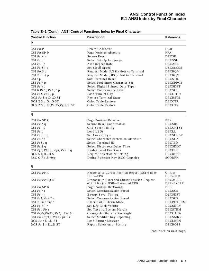
ANSI Control Function IndexE.1 ANSI Index by Final Character
Table E–1 (Cont.) ANSI Control Functions Index by Final Character
Control Function Description Reference
P
CSI Pn P Delete Character DCHCSI Pn SP P Page Position Absolute PPACSI Pr + p Secure Reset DECSRCSI Ps p Select Set-Up Language DECSSLCSI Ps - p Auto Repeat Rate DECARRCSI Ps SP p Set Scroll Speed DECSSCLSCSI Pa $ p Request Mode (ANSI) Host to Terminal DECRQMCSI ? Pd $ p Request Mode (DEC) Host to Terminal DECRQMCSI ! p Soft Terminal Reset DECSTRCSI Ps * p Select ProPrinter Character Set DECSPPCSCSI Ps ) p Select Digital Printed Data Type DECSDPTCSI 6 Ps1 ; Ps2 ; " p Select Conformance Level DECSCLCSI Ps1; Ps2 , p Load Time of Day DECLTODDCS Ps $ p D...D ST Restore Terminal State DECRSTSDCS 2 $ p D...D ST Color Table Restore DECCTRDCS 2 $ p Pc;Pu;Px;Py;Pz/ ST Color Table Restore DECCTR
Q
CSI Pn SP Q Page Position Relative PPRCSI Pr * q Secure Reset Confirmation DECSRCCSI Ps - q CRT Saver Timing DECCRTSTCSI Ps q Load LEDs DECLLCSI Ps SP q Set Cursor Style DECSCUSRCSI Ps " q Select Character Protection Attribute DECSCACSI Ps1 , q Select Terminal ID DECTIDCSI Ps $ q Select Disconnect Delay Time DECSDDTCSI Pf1; PC1; ...Pfn; Pcn + q Enable Local Functions DECELFDCS $ q D...D ST Request Selection or Setting DECRQSSESC Q Fn String Define Function Key (SCO Console) SCODFK
R
CSI Pl; Pc R Response to Cursor Position Report (CSI 6 n) orDSR—CPR
CPR orDSR–CPR
CSI Pl; Pc; Pp R Response to Extended Cursor Position Request(CSI ? 6 n) or DSR—Extended CPR
DECXCPR,DSR–ExCPR
CSI Pn SP R Page Position Backwards PPBCSI Ps * r Select Communication Speed DECSCSCSI Ps - r Energy Saver Timing DECSESTCSI Ps1; Ps2 * r Select Communication Speed DECSCSCSI ? Ps1; Ps2 r Enter/Exit PCTerm Mode DECPCTERMCSI Ps SP r Set Key Click Volume DECSKCVCSI Pt ; Pb r Set Top and Bottom Margin DECSTBMCSI Pt;Pl;Pb;Pr; Ps1;...Psn $ r Change Attribute in Rectangle DECCARACSI Pm1;Pf1;...Pmn;Pfn + r Select Modifier Key Reporting DECSMKRDCS Ps r D...D ST Load Banner Message DECLBANDCS Ps $ r D...D ST Report Selection or Setting DECRQSS
(continued on next page)
ANSI Control Function Index E–7

ANSI Control Function IndexE.1 ANSI Index by Final Character
Table E–1 (Cont.) ANSI Control Functions Index by Final Character
Control Function Description Reference
S
CSI s Save Current Cursor Position (SCO Console) SCOSCCSI Pn S Pan Down SUCSI Pl ; Pr s Set Left and Right Margin DECSLRMCSI Ps $ s Select Printer Type DECSPRTTCSI Ps * s Select Flow Control Type DECSFCCSI Ps1; Ps2; Ps3; Ps4 * s Select Flow Control DECSFCDCS 1 $ s D...D ST Reply to Terminal State Report to Host DECTSRDCS 2 $ s D...D ST Color Table Report DECCTRDCS Ps $ s D...D ST Reply to Terminal State Report DECRQTSR
T
CSI Pn T Pan Up SDCSI Pn t Set Lines Per Page DECSLPPCSI Ps SP t Set Warning Bell Volume DECSWBVCSI Pt;Pl;Pb;Pr Ps1;...Psn $ t Reverse Attribute in Rectangle DECRARADCS Ps $ t D...D ST Restore Presentation State DECRSPS
U
CSI u Restore Saved Cursor Position (SCO Console) SCORCCSI Pn U Next Page NPCSI & u Request User-Preferred Supplemental Set DECRQUPSSCSI 1 $ u Request Terminal State Report DECTSRCSI Ps $ u Request Terminal State Report DECRQTSRCSI 2; Pu $ u Color Table Request DECCTRCSI Ps , u Key Type Inquiry DECRQKTCSI Ps SP u Set Margin Bell Volume DECSMBVCSI Ps * u Select Communication Port DECSCPCSI Ps1; Ps2 * u Select Communication Port DECSCPCSI Ps " u Set Transmit Rate Limit DECSTRLCSI Ps1; Ps2 " u Set Transmit Rate Limit DECSTRLDCS 1 $ u D...D ST Cursor Information Report DECCIRDCS 2 $ u D...D ST Tab Stop Report DECTABSRDCS Ps ! u Dscs ST Assign User-Preferred Supp Set DECAUPSS
V
CSI Pn V Preceding Page PPCSI Ps SP v Set Lock Key Style DECSLCKCSI " v Request Displayed Extent DECRQDECSI Ps1 ; Ps2 , v Report Key Type DECRPKTCSIPts;Pls;Pbs;Prs;Pps;Ptd;Pld;Ppd$v Copy Rectangular Area DECCRADCS Ps v D...D ST Load Answerback Message DECLANS
W
CSI ? 5 W Set Tab at every 8 columns DECST8CCSI Ps + w Set Port Parameter DECSPPCSI Ps1 ; Ps2 , w Key Definition Inquiry DECRQKD
(continued on next page)
E–8 ANSI Control Function Index

ANSI Control Function IndexE.1 ANSI Index by Final Character
Table E–1 (Cont.) ANSI Control Functions Index by Final Character
Control Function Description Reference
W
CSI Ps1; Ps2; Ps3; Ps4 + w Set Port Parameter DECSPPCSI Ph;Pw;Pml;Pmt;Pmp; " w Report Displayed Extent DECRPDECSI Ps $ w Request Presentation State Report DECRQPSR
X
CSI Pn X Erase Character(s) ECHCSI & x Enable Session DECESCSI Pch; Pt;Pl;Pb;Pr $ x Fill Rectangular Area DECFRACSI Pn1;Pn2;Pn3;Pn4 , x Session Page Memory Allocation DECSPMACSI Ps * x Select Attribute and Change Extent DECSACECSI + x Program Key Free Memory Inquiry DECRQPKFMDCS " x D...D ST Program Function Key DECPFK
Y
CSI Pa; Ps $ y Report Mode (ANSI) Terminal to Host DECRPMCSI ? Pd; Ps $ y Report Mode (DEC) Terminal to Host DECRPMCSI Pid;Pp;Pt;Pl;Pb;Pr * y Request Checksum of Rectangle Area DECRQCRACSI 4 ; Ps ; ... ; Ps y Invoke Confidence Test DECTSTCSI Ps1; Ps2 + y Program Key Free Memory Report DECPKFMRCSI Ps , y Update Session DECUSDCS " y D...D ST Program Alphanumeric Key DECPAK
Z
CSI Pt;Pl;Pb;Pr $ z Erase Rectangular Area DECERACSI Pid * z Invoke Macro DECINVMCSI Pn Z Cursor Backward Tabulation CBTCSI Ps , z Down Line Load Allocation DECDLDACSI Ps + z Program Key Action DECPKADCS Pid;Pdt;Pen ! z D...D ST Define Macro DECDMACDCS " z D...D ST Copy Key Default DECCKDESC Z Identify Device (Use DA1 instead.) DECID
Other Characters
APC : ppp mm ST Extended Keyboard Report DECEKBDCSI Pn @ Insert Character ICH
CSI Ps1;Ps2;Ps3 , | Assign Color DECACCSI Pn * | Select number of lines per screen DECSNLSCSI $ | Set 80 columns per page DECSCPPCSI Ps $ | Set Ps columns per page DECCOLMCSI 80 $ | Set 80 columns per page DECSCPPCSI 132 $ | Set 132 columns per page DECSCPPDCS ! | D...D ST Report Terminal Unit ID, response
to Tertiary Device AttributesDA3 andDECRPTUI
DCS Ps1; Ps2; Ps3 | D...D ST User Defined Key DECUDKESC | Locking Shift Three Right LS
(continued on next page)
ANSI Control Function Index E–9

ANSI Control Function IndexE.1 ANSI Index by Final Character
Table E–1 (Cont.) ANSI Control Functions Index by Final Character
Control Function Description Reference
Other Characters
CSI Pn * { Macro Space Report Response DECMSR,DSR–MSR
CSI Ps ) { Select Color Look-Up Table DECSTGLTCSI Ps , { Select Zero Symbol DECSZSCSI Pt;Pl;Pb;Pr $ { Selective Erase Rectangular Area DECSERADCS ! { D...D ST Set Terminal Unit ID DECSTUIDCS Pfn; Pcn; Pe; Pcmw; Pss; Pu;Pcmh; Pcss f <Dscs><sixel-font-patterns> ST
Dynamically Redefinable Character Sets Extension(Down-line Load)
DECDLD
CSI Pn ’ } Insert Column DECICCSI Ps $ } Select Active Status Display DECSASDCSI Ps1; Ps2; Ps3 , g Alternate Text Colors DECATCCSI Ps1; Ps2 SP g Keyboard Language Selection DECKBDCSI Pk1; Pf1; Pk2; Pf2.....* g Local Function Key Control DECLFKCDCS " g D...D ST Report Function Key Definition DECRPFKESC } Locking Shift Two Right LS
CSI Pn ‘ Horizontal Position Absolute HPACSI Pn ’ ~ Delete Column(s) DECDCCSI Ps SP ~ Terminal Mode Emulation DECTMECSI Ps $ ~ Set Status Display (Line) Type DECSSDTCSI Ps1 ; Ps2 ~ Function Key DECFNKCSI D...D , ~ Play Sound DECPSDCS " ~ D...D ST Report all Modifiers/Alphanumeric Key State DECRPAKDCS Pid ! ~ D...D ST Response to Memory Checksum Report Request DECRQCRA,
DECCKSR, orDSR–Mem
ESC ~ Locking Shift One Right LSESC ( Dscs G0 94-character set SCSESC ) Dscs G1 94-character set SCSESC * Dscs G2 94-character set SCSESC + Dscs G3 94-character set SCSESC - Dscs G1 96-character set SCSESC . Dscs G2 96-character set SCSESC / Dscs G3 96-character set SCSESC = Set Keypad Application Mode DECKPAMESC < Exit ANSI (VT52) Mode DECANMESC > Reset Keypad to numeric characters DECKPNMS0 Locking Shift One LS
E–10 ANSI Control Function Index

Glossary
Active Session
The session to which keyboard input is currently directed.
ANSI
American National Standards Institute; ANSI character set.
ANSI Standard Color
Support for specifying text colors using the Select Graphic Rendition (SGR)command and parameters defined in ANSI X3.64.
ANSI Terminal
A video terminal that complies with prominent ANSI standards, which usuallyinclude:
ANSI X3.4, ASCII, American Standard Code for Information ExchangeANSI X3.41 Controls for use with ASCIIANSI X3.64 Additional Controls for use with ASCII
ASCII
American Standard Code for Information Interchange; ASCII character set.
ASCII Terminal
A video terminal that complies with:
ANSI X3.4 ASCII, American Standard Code for Information ExchangeANSI X3.41 Controls for use with ASCII
But an ASCII terminal may not comply with control sequences, the protocoldefined by ANSI X3.64, Additional Controls for use with ASCII.
Character Set
A one-to-one mapping between the character codes and the symbols produced.The differences are as follows:
Character Set Character Codes Control Codes
ASCII 7-bit 96 32
ASCII 8-bit 192 64
PC 256 0
PCTerm 256 16 (typically)
Glossary–1
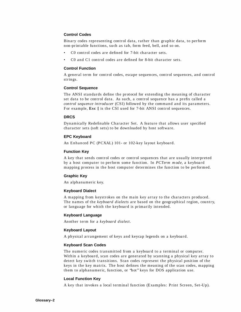
Control Codes
Binary codes representing control data, rather than graphic data, to performnon-printable functions, such as tab, form feed, bell, and so on.
• C0 control codes are defined for 7-bit character sets.
• C0 and C1 control codes are defined for 8-bit character sets.
Control Function
A general term for control codes, escape sequences, control sequences, and controlstrings.
Control Sequence
The ANSI standards define the protocol for extending the meaning of characterset data to be control data. As such, a control sequence has a prefix called acontrol sequence introducer (CSI) followed by the command and its parameters.For example, Esc [ is the CSI used for 7-bit ANSI control sequences.
DRCS
Dynamically Redefinable Character Set. A feature that allows user specifiedcharacter sets (soft sets) to be downloaded by host software.
EPC Keyboard
An Enhanced PC (PCXAL) 101- or 102-key layout keyboard.
Function Key
A key that sends control codes or control sequences that are usually interpretedby a host computer to perform some function. In PCTerm mode, a keyboardmapping process in the host computer determines the function to be performed.
Graphic Key
An alphanumeric key.
Keyboard Dialect
A mapping from keystrokes on the main key array to the characters produced.The names of the keyboard dialects are based on the geographical region, country,or language for which the keyboard is primarily intended.
Keyboard Language
Another term for a keyboard dialect.
Keyboard Layout
A physical arrangement of keys and keycap legends on a keyboard.
Keyboard Scan Codes
The numeric codes transmitted from a keyboard to a terminal or computer.Within a keyboard, scan codes are generated by scanning a physical key array todetect key switch transitions. Scan codes represent the physical position of thekeys in the key matrix. The host defines the meaning of the scan codes, mappingthem to alphanumeric, function, or ‘‘hot’’ keys for DOS application use.
Local Function Key
A key that invokes a local terminal function (Examples: Print Screen, Set-Up).
Glossary–2

MPR II
A Swedish standard that sets limits for low frequency magnetic energy emittedfrom electronic equipment.
PCTerm
A terminal mode that emulates the console of an industry-standard PC, whilecommunicating with a host over a serial communications line. PCTerm modeallows you to run an application on a host as if the application was runninglocally on the terminal. In PCTerm mode, the terminal transmits the same PCkeyboard scan codes that a console keyboard attached to a PC would send.
Session
A connection between a single virtual terminal and a host computer.
Set-Up Summary Line
A line of text that appears at the bottom of the screen any time the terminal is inSet-Up. This line summarizes how the terminal is configured. If the terminal isunable to communicate with a host for some reason, the Set-Up Summary Linecan be used to quickly find any mismatched settings.
Soft Key Mapping
The ability to modify the correspondence between keystrokes to character codesor functions for all keys on the keyboard.
Status Display
A separate logical display that usually appears as a single line near the bottomor top of the screen to provide status information.
TD/SMP
Terminal Device/Session Management Protocol. A communications protocol thatallows multiple sessions to share a single comm port.
User Defined Key
A function key that can be reprogrammed by the user or by a control sequencefrom the host.
Virtual Terminal
A virtual terminal appears to be a real physical terminal to a host computer butmay in fact share resources with other virtual terminals (keyboard and display)to create the effect of more than one terminal within a single device. Virtualterminals maintain the full state and context of real physical terminals.
VT Keyboard
An LK450 (LK411) 108-key layout keyboard.
XOFF/XON
Control codes that the terminal uses to stop and resume transmission when itsreceive buffer (or the host’s receive buffer) is full or empty.
Glossary–3

XPC
A remapping of transmitted XOFF and XON control codes to unused PC scancodes. While in PCTerm mode, these control codes would interfere with the scancodes that the host expects to receive. The terminal, however, still responds toreceived XOFF and XON control codes.
Glossary–4
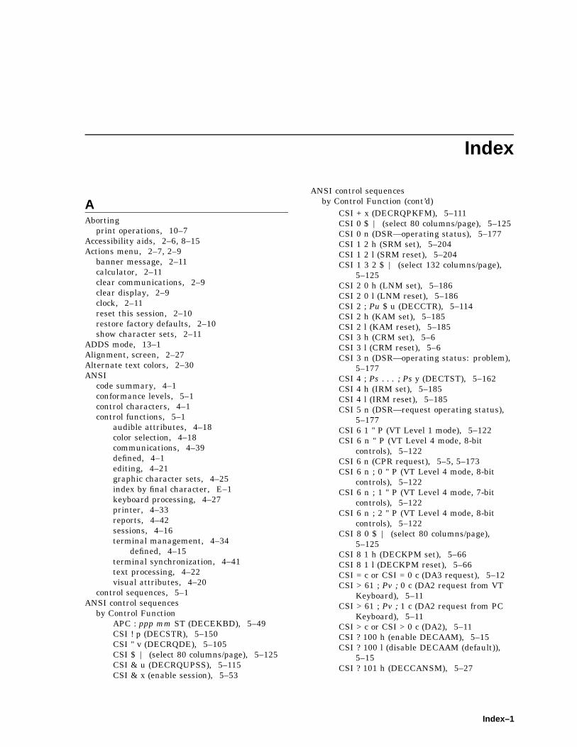
Index
AAborting
print operations, 10–7Accessibility aids, 2–6, 8–15Actions menu, 2–7, 2–9
banner message, 2–11calculator, 2–11clear communications, 2–9clear display, 2–9clock, 2–11reset this session, 2–10restore factory defaults, 2–10show character sets, 2–11
ADDS mode, 13–1Alignment, screen, 2–27Alternate text colors, 2–30ANSI
code summary, 4–1conformance levels, 5–1control characters, 4–1control functions, 5–1
audible attributes, 4–18color selection, 4–18communications, 4–39defined, 4–1editing, 4–21graphic character sets, 4–25index by final character, E–1keyboard processing, 4–27printer, 4–33reports, 4–42sessions, 4–16terminal management, 4–34
defined, 4–15terminal synchronization, 4–41text processing, 4–22visual attributes, 4–20
control sequences, 5–1ANSI control sequences
by Control FunctionAPC : ppp mm ST (DECEKBD), 5–49CSI ! p (DECSTR), 5–150CSI " v (DECRQDE), 5–105CSI $ | (select 80 columns/page), 5–125CSI & u (DECRQUPSS), 5–115CSI & x (enable session), 5–53
ANSI control sequencesby Control Function (cont’d)
CSI + x (DECRQPKFM), 5–111CSI 0 $ | (select 80 columns/page), 5–125CSI 0 n (DSR—operating status), 5–177CSI 1 2 h (SRM set), 5–204CSI 1 2 l (SRM reset), 5–204CSI 1 3 2 $ | (select 132 columns/page),
5–125CSI 2 0 h (LNM set), 5–186CSI 2 0 l (LNM reset), 5–186CSI 2 ; Pu $ u (DECCTR), 5–114CSI 2 h (KAM set), 5–185CSI 2 l (KAM reset), 5–185CSI 3 h (CRM set), 5–6CSI 3 l (CRM reset), 5–6CSI 3 n (DSR—operating status: problem),
5–177CSI 4 ; Ps . . . ; Ps y (DECTST), 5–162CSI 4 h (IRM set), 5–185CSI 4 l (IRM reset), 5–185CSI 5 n (DSR—request operating status),
5–177CSI 6 1 " P (VT Level 1 mode), 5–122CSI 6 n " P (VT Level 4 mode, 8-bit
controls), 5–122CSI 6 n (CPR request), 5–5, 5–173CSI 6 n ; 0 " P (VT Level 4 mode, 8-bit
controls), 5–122CSI 6 n ; 1 " P (VT Level 4 mode, 7-bit
controls), 5–122CSI 6 n ; 2 " P (VT Level 4 mode, 8-bit
controls), 5–122CSI 8 0 $ | (select 80 columns/page),
5–125CSI 8 1 h (DECKPM set), 5–66CSI 8 1 l (DECKPM reset), 5–66CSI = c or CSI = 0 c (DA3 request), 5–12CSI > 61 ; Pv ; 0 c (DA2 request from VT
Keyboard), 5–11CSI > 61 ; Pv ; 1 c (DA2 request from PC
Keyboard), 5–11CSI > c or CSI > 0 c (DA2), 5–11CSI ? 100 h (enable DECAAM), 5–15CSI ? 100 l (disable DECAAM (default)),
5–15CSI ? 101 h (DECCANSM), 5–27
Index–1

ANSI control sequencesby Control Function (cont’d)
CSI ? 101 l (DECCANSM ), 5–27CSI ? 1 0 2 h (DECNULM set), 5–76CSI ? 1 0 2 l (DECNULM reset), 5–76CSI ? 1 0 3 h (DECHDPXM enabled
/half-duplex enabled), 5–56CSI ? 1 0 3 l (DECHDPXM disabled
/full-duplex enabled), 5–56CSI ? 1 0 4 h (secondary keyboard mapping
- DECESKM), 5–53CSI ? 1 0 4 l (primary keyboard mapping -
DECESKM), 5–53CSI ? 1 0 6 h (DECOSCNM set), 5–77CSI ? 1 0 6 l (DECOSCNM reset), 5–77CSI ? 10 n (DSR—printer ready), 5–178CSI ? 111 h (enable (set) framed windows
mode - default), 5–56CSI ? 111 l (disable (reset) framed windows
mode), 5–56CSI ? 112 h (enable (set) review previous
lines mode ), 5–97CSI ? 112 l (disable (reset) review previous
lines mode - default), 5–97CSI ? 113 h (enable (set) host wake-up),
5–59CSI ? 113 l (disable (reset) host wake-up
mode), 5–59CSI ? 11 n (DSR—printer assigned to other
session), 5–178CSI ? 11 n (DSR—printer not ready),
5–178CSI ? 13 n (DSR—no printer), 5–178CSI ? 15 n (DSR—printer port request),
5–178CSI ? 1 8 h (DECPFF set), 5–83CSI ? 1 8 l (DECPFF reset), 5–83CSI ? 18 n (DSR—printer busy), 5–178CSI ? 1 9 h (DECPEX set), 5–83CSI ? 1 9 l (DECPEX reset), 5–83CSI ? 1 h (DECCKM set), 5–32CSI ? 1 l (DECCKM reset), 5–32CSI ? 20 n (DSR—UDKs unlocked), 5–179CSI ? 21 n (DSR—UDKs unlocked), 5–179CSI ? 2 5 h (DECTCEM set), 5–157CSI ? 2 5 l (DECTCEM reset), 5–157CSI ? 25 n (DSR—UDK request), 5–179CSI ? 26 n (DSR— keyboard status
request), 5–175CSI ? 27 ; Pn ; Pst ; Ptyp n (DSR—keyboard
status reply), 5–175CSI ? 2 l (DECANM), 5–18CSI ? 3 4 h (DECPCCM set), 5–80CSI ? 3 4 h (DECRLM set), 5–93CSI ? 3 4 l (DECPCCM reset), 5–80CSI ? 3 4 l (DECRLM reset), 5–93CSI ? 3 5 h (DECHEBM reset), 5–58CSI ? 3 5 l (DECHEBM set), 5–58
ANSI control sequencesby Control Function (cont’d)
CSI ? 3 6 h (DECHEM set), 5–57CSI ? 3 6 l (DECHEM reset), 5–57CSI ? 3 h (DECCOLM set), 5–34CSI ? 3 l (DECCOLM reset), 5–34CSI ? 4 2 h (DECNRCM set), 5–75CSI ? 4 2 l (DECNRCM reset), 5–75CSI ? 4 h (DECSCLM set), 5–123CSI ? 4 l (DECSCLM reset), 5–123CSI ? 5 7 h (DECNAKB set), 5–74CSI ? 5 7 l (DECNAKB reset), 5–74CSI ? 58 h (DECIPEM - enter IBM
ProPrinter emulation mode), 5–62CSI ? 58 l (DECIPEM - exit IBM ProPrinter
emulation mode), 5–62CSI ? 5 h (DECSCNM set), 5–123CSI ? 5 l (DECSCNM reset), 5–123CSI ? 5 W (DECST8C), 5–149CSI ? 6 1 h (DECVCCM set), 5–170CSI ? 6 1 l (DECVCCM reset), 5–170CSI ? 62 n (DSR—macro space request),
5–176CSI ? 63; Pid n (DSR—memory checksum
request), 5–177CSI ? 65 ; Ps1 ; ... ; Psn c (DA1 response),
5–9CSI ? 6 6 h (DECNKM set), 5–75CSI ? 6 6 l (DECNKM reset), 5–75CSI ? 6 7 h (DECBKM set), 5–26CSI ? 6 7 l (DECBKM reset), 5–26CSI ? 6 8 h (DECKBUM set), 5–65CSI ? 6 8 l (DECKBUM reset), 5–65CSI ? 6 9 h (DECLRMM set), 5–72CSI ? 6 9 l (DECLRMM reset), 5–72CSI ? 6 h (DECOM set), 5–77CSI ? 6 l (DECOM reset), 5–77CSI ? 6 n (CPR request), 5–174CSI ? 70 n (DSR—data integrity report),
5–174CSI ? 71 n (DSR—data integrity report),
5–174CSI ? 7 3 h (DECXRLM set), 5–171CSI ? 7 3 l (DECXRLM reset), 5–171CSI ? 73 n (DSR—data integrity report),
5–174CSI ? 75 n (DSR—data integrity request),
5–174CSI ? 7 h (DECAWM set), 5–25CSI ? 7 l (DECAWM reset), 5–25CSI ? 8 h (DECARM set), 5–19CSI ? 8 l (DECARM reset), 5–19CSI ? 9 5 h (DECNCSM set), 5–74CSI ? 9 5 l (DECNCSM reset), 5–74CSI ? 9 6 h (DECRLCM disabled), 5–92CSI ? 9 6 h (DECRLCM enabled), 5–92CSI ? 97 h (CRT saver enabled), 5–37CSI ? 97 l (CRT saver disabled), 5–37
Index–2
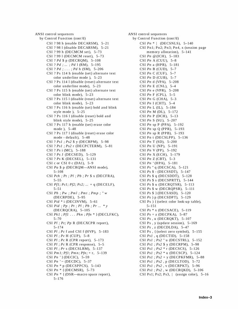
ANSI control sequencesby Control Function (cont’d)
CSI ? 98 h (enable DECARSM), 5–21CSI ? 98 l (disable DECARSM), 5–21CSI ? 99 h (DECMCM set), 5–73CSI ? 99 l (DECMCM reset), 5–73CSI ? Pd $ p (DECRQM), 5–108CSI ? Pd ; ... ; Pd l (RM), 5–195CSI ? Pd ; . . . ; Pd h (SM), 5–206CSI ? Ps 114 h (enable (set) alternate text
color underline mode ), 5–23CSI ? Ps 114 l (disable (reset) alternate text
color underline mode), 5–23CSI ? Ps 115 h (enable (set) alternate text
color blink mode), 5–23CSI ? Ps 115 l (disable (reset) alternate text
color blink mode), 5–23CSI ? Ps 116 h (enable (set) bold and blink
style mode ), 5–25CSI ? Ps 116 l (disable (reset) bold and
blink style mode), 5–25CSI ? Ps 117 h (enable (set) erase color
mode ), 5–48CSI ? Ps 117 l (disable (reset) erase color
mode - default), 5–48CSI ? Ps1 ; Ps2 $ y (DECRPM), 5–98CSI ? Ps1 ; Ps2 r (DECPCTERM), 5–81CSI ? Ps i (MC), 5–188CSI ? Ps J (DECSED), 5–129CSI ? Ps K (DECSEL), 5–131CSI c or CSI 0 c (DA1), 5–9CSI Pa $ p (DECRQM—ANSI mode),
5–108CSI Pch ; Pt ; Pl ; Pb ; Pr $ x (DECFRA),
5–55CSI Pf1; Pc1; Pf2; Pc2; ... + q (DECELF),
5–51CSI Ph ; Pw ; Pml ; Pmt ; Pmp ; " w
(DECRPDE), 5–95CSI Pid * i (DECINVM), 5–61CSI Pid ; Pp ; Pt ; Pl ; Pb ; Pr ... * y
(DECRQCRA), 5–105CSI Pk1 ; Pf1 . . . Pkn ; Pfn * } (DECLFKC),
5–70CSI Pl ; Pc; Pp R (DECXCPR report),
5–174CSI Pl ; Pc f and CSI f (HVP), 5–183CSI Pl ; Pc H (CUP), 5–8CSI Pl ; Pc R (CPR report), 5–173CSI Pl ; Pc R (CPR response), 5–5CSI Pl ; Pr s (DECSLRM), 5–137CSI Pm1; Pf1; Pmn; Pfn; + r, 5–139CSI Pn ’ } (DECIC), 5–59CSI Pn ’ ~ (DECDC), 5–37CSI Pn * p (DECSPPCS), 5–143CSI Pn * { (DECMSR), 5–73CSI Pn * { (DSR—macro space report),
5–176
ANSI control sequencesby Control Function (cont’d)
CSI Pn * | (DECSNLS), 5–140CSI Pn1; Pn2; Pn3; Pn4, x (session page
memory allocation), 5–141CSI Pn @ (ICH), 5–183CSI Pn A (CUU), 5–8CSI Pn a (HPR), 5–181CSI Pn B (CUD), 5–7CSI Pn C (CUF), 5–7CSI Pn D (CUB), 5–7CSI Pn d (VPA), 5–208CSI Pn E (CNL), 5–4CSI Pn e (VPR), 5–208CSI Pn F (CPL), 5–5CSI Pn G (CHA), 5–3CSI Pn I (CHT), 5–4CSI Pn L (IL), 5–184CSI Pn M (DL), 5–172CSI Pn P (DCH), 5–13CSI Pn S (SU), 5–207CSI Pn sp P (PPA), 5–192CSI Pn sp Q (PPR), 5–193CSI Pn sp R (PPB), 5–193CSI Pn t (DECSLPP), 5–136CSI Pn T (SD), 5–200CSI Pn U (NP), 5–191CSI Pn V (PP), 5–192CSI Pn X (ECH), 5–179CSI Pn Z (CBT), 5–3CSI Pn ‘ (HPA), 5–181CSI Ps " q (DECSCA), 5–121CSI Ps $ - (DECSSDT), 5–147CSI Ps $ q (DECSDDT), 5–128CSI Ps $ s (DECSPRTT), 5–144CSI Ps $ u (DECRQTSR), 5–113CSI Ps $ w (DECRQPSR), 5–111CSI Ps $ } (DECSASD), 5–120CSI Ps ) p (DECSDPT), 5–129CSI Ps ) { (select color look-up table),
5–151CSI Ps * x (DECSACE), 5–119CSI Ps + z (DECPKA), 5–87CSI Ps , u (DECRQKT), 5–107CSI Ps , y (update session), 5–169CSI Ps , z (DECDLDA), 5–47CSI Ps , { (select zero symbol), 5–155CSI Ps1 , q (DECTID), 5–158CSI Ps1 ; Ps2 " u (DECSTRL), 5–152CSI Ps1 ; Ps2 $ y (DECRPM), 5–98CSI Ps1 ; Ps2 * r (DECSCS), 5–126CSI Ps1 ; Ps2 * u (DECSCP), 5–124CSI Ps1 ; Ps2 + y (DECPKFMR), 5–88CSI Ps1 ; Ps2 , p (DECLTOD), 5–72CSI Ps1 ; Ps2 , v (DECRPKT), 5–96CSI Ps1 ; Ps2 , w (DECRQKD), 5–106CSI Ps1; Ps2; Ps3, | (assign color), 5–16
Index–3

ANSI control sequencesby Control Function (cont’d)
CSI Ps1; Ps2; Ps3, } (alternate text color),5–22
CSI Ps1 ; Ps2 ; Ps3 ; Ps4 * s (DECSFC),5–133
CSI Ps1 ; Ps2 ; Ps3 ; Ps4 + w (DECSPP),5–142
CSI Ps1 ; Ps2 SP } (DECKBD), 5–63CSI Ps ; Ps ; Ps m (SGR), 5–201CSI Ps g (TBC), 5–207CSI Ps i (MC - ANSI standard), 5–188CSI Ps J (ED), 5–180CSI Ps K (EL), 5–180CSI Ps p (DECSSL), 5–148CSI Ps - p (select auto repeat rate), 5–20CSI Ps - q (CRT saver timing), 5–36CSI Ps - r (energy saver timing), 5–130CSI Ps SP p (DECSSCLS), 5–146CSI Ps SP q (DECSCUSR), 5–127CSI Ps SP r (DECSKCV), 5–135CSI Ps SP t (DECSWBV), 5–154CSI Ps SP u (DECSMBV), 5–138CSI Ps SP v (DECSLCK), 5–135CSI Ps SP ~ (DECTME), 5–159CSI Pt ; Pb r (DECSTBM), 5–149CSI Pt ; Pl ; Pb ; Pr $ z (DECERA), 5–52CSI Pt ; Pl ; Pb ; Pr $ { (DECSERA), 5–132CSI Pt ; Pl ; Pb; Pr ; Ps1 ;... Psn $ r
(DECCARA), 5–28CSI Pt ; Pl ; Pb ; Pr ; Ps1 ;...Psn $ t
(DECRARA), 5–90CSI Pts ; Pls ; Pbs ; Prs ; Pps ; Ptd ; Pld ;
Ppd $ v (DECCRA), 5–35CSI Pvolume; Pduration; Pnote, ~ (play
sound), 5–89CSI s (SCOSC), 6–9CSI u (SCORC), 6–9DCS ! { D...D ST (DECSTUI), 5–153DCS ! | D...D ST (DA3 response), 5–12DCS ! | D...D ST (DECRPTUI), 5–104DCS " x D . . . D ST (DECPFK), 5–84DCS " y D . . . D ST (DECPAK), 5–78DCS " z D...D ST (DECCKD), 5–31DCS " } D . . . D ST (DECRPFK), 5–96DCS " ~ D . . . D ST (DECRPAK), 5–94DCS $ q D . . . D ST (DECRQSS request),
5–112DCS 1 $ s D...D ST (DECTSR), 5–160DCS 1 $ u D...D ST (DECCIR), 5–30DCS 2 $ p D...D ST (DECRSTS), 5–118DCS 2 $ p D...D ST (DECTSR), 5–161DCS 2 $ u D...D ST (DECTABSR), 5–157DCS Dscs ! u Pd ST (DECAUPSS), 5–24DCS Pfn ; Pcn; Pe; Pcmw; Pss; Pu; Pcmh;
Pcss { <Dscs><sixel-font-pattern> ST(DECDLD), 5–39
ANSI control sequencesby Control Function (cont’d)
DCS Pid ! ~ D...D ST (DSR —memorychecksum report), 5–177
DCS Pid ; Pdt ; Pen ! z D . . . D ST(DECDMAC), 5–45
DCS Ps $ p D...D ST (DECRSTS), 5–117DCS Ps $ r D . . . D ST (DECRPSS), 5–102DCS Ps $ t D...D ST (DECRSPS), 5–116DCS Ps1 ; Ps2 ; Ps3 | D . . . D ST
(DECUDK), 5–163DCS Ps r D . . . D ST (DECLBAN), 5–69DCS Ps v D . . . D ST (DECLANS), 5–68ESC # 3 (top), ESC # 4 (bottom) (DECDHL),
5–38ESC # 5 (DECSWL), 5–154ESC # 6 (DECDWL), 5–48ESC # 8 (DECALN), 5–17ESC ( 1 (DDD3), 5–14ESC ) 1 (DDD1), 5–14ESC ) B (DDD2), 5–14ESC 6 (DECBI), 5–26ESC 7 (DECSC), 5–120ESC 8 (DECRC), 5–92ESC 9 (DECFI), 5–54ESC < (exit DECANM), 5–19ESC = (DECKPAM), 5–66ESC > (DECKPNM), 5–67ESC c (RIS), 5–194ESC I Dscs (SCS), 5–197ESC n (locking shift G2), 5–187ESC o (locking shift G3), 5–187ESC Q Fn String (SCODFK), 6–7ESC sp F (S7C1T), 5–196ESC sp final (ANSI conformance level),
5–1ESC sp G (S8C1T), 5–196ESC Z (DECID), 5–60ESC [ ? 108 h (DECNUMLK set), 5–76ESC [ ? 108 l (DECNUMLK reset), 5–76ESC [ ? 109 h (DECCAPSLK set), 5–28ESC [ ? 109 l (DECCAPSLK reset), 5–28ESC [ ? 110 h (DECKLHIM set), 5–65ESC [ ? 110 l (DECKLHIM reset), 5–65ESC [ Pr * q (DECSR), 5–146ESC [ Pr + p (DECSR), 5–144ESC [ Ps q (DECLL), 5–71ESC | (locking shift G3 right), 5–187ESC } (locking shift G2 right), 5–187ESC ~ (locking shift G1 right), 5–187HT (HT), 5–182HTS (HTS), 5–182OSC 2 D...D ST (set icon name), 5–134OSC 2 D...D ST (set window title), 5–156SI (locking shift G0), 5–187SO (locking shift G1), 5–187SS2 (single shift G2), 5–205SS3 (single shift G3), 5–205
Index–4

ANSI control sequences (cont’d)by Control Sequence
CSI ? 6 3 ; Pid n (DECCKSR request),5–33
DCS Pid ! ~ D . . . D ST (DECCKSRresponse), 5–33
ESC D (IND), 5–184ESC E (NEL), 5–191
by MnemonicCBT (cursor backward tabulation), 5–3CHA (cursor horizontal absolute), 5–3CHT (cursor horizontal forward tabulation),
5–4CNL (cursor next line), 5–4CPL (cursor previous line), 5–5CPR (cursor position report), 5–5, 5–173CRM (show control character mode), 5–6CUB (cursor backward), 5–7CUD (cursor down), 5–7CUF (cursor forward), 5–7CUP (cursor position), 5–8CUU (cursor up), 5–8DA1 (primary device attributes), 5–9DA2 (secondary device attributes), 5–11DA3 (tertiary device attributes), 5–12DCH (delete character), 5–13DDD1 (DDD1), 5–14DDD2 (DDD2), 5–14DDD3 (DDD3), 5–14DECAAM (set/reset auto answerback
mode), 5–15DECAC (Assign color), 5–16DECALN (screen alignment pattern), 5–17DECANM (ANSI mode), 5–18DECANM (exiting ANSI (VT52) mode),
5–19DECARM (autorepeat mode), 5–19DECARR (Select auto repeat rate), 5–20DECARSM (set/reset auto resize mode),
5–21DECATC (Alternate text color), 5–22DECATCBM (Set/reset alternate text color
blink mode), 5–23DECATCUM (Set/reset alternate text color
underline mode), 5–23DECAUPSS (assigning user-preferred
supplemental sets), 5–24DECAWM (autowrap mode), 5–25DECBBSM (bold and blink style mode),
5–25DECBI (back index), 5–26DECBKM (backarrow key mode), 5–26DECCANSM (conceal answerback message
mode), 5–27DECCAPSLK (caps lock mode), 5–28DECCARA (change attributes in
rectangular area), 5–28DECCIR (cursor information report), 5–30
ANSI control sequencesby Mnemonic (cont’d)
DECCKD (copy key default), 5–31DECCKM (cursor keys mode), 5–32DECCKSR (memory checksum), 5–33,
5–177DECCOLM (column mode), 5–34DECCRA (copy rectangular area), 5–35DECCRTSM (set/reset CRT save mode),
5–37DECCRTST (CRT saver timing), 5–36DECCTR (color table request), 5–114DECDC (delete column), 5–37DECDHL (double-width, double-height
line), 5–38DECDLD (dynamically redefinable
character sets extension), 5–39DECDLDA (down-line load allocation),
5–47DECDMAC (define macro), 5–45DECDWL (double-width, single-height
line), 5–48DECECM (Erase color mode), 5–48DECEKBD (extended keyboard report),
5–49DECELF (enable local functions), 5–51DECERA (erase rectangular area), 5–52DECES (Enable session), 5–53DECESKM (enable secondary keyboard
language mode), 5–53DECFI (forward index), 5–54DECFRA (fill rectangular area), 5–55DECFWM (Set/reset framed windows
mode), 5–56DECHDPXM (set/reset half-duplex mode),
5–56DECHEBM (Hebrew/N-A keyboard
mapping), 5–58DECHEM (Hebrew encoding mode), 5–57DECHWUM (Host wake-up mode), 5–59DECIC (insert column), 5–59DECID (identify device), 5–60DECINVM (invoke macro), 5–61DECIPEM (enter/return from IBM
ProPrinter emulation mode), 5–62DECKBD (keyboard language selection),
5–63DECKBUM (keyboard usage mode), 5–65DECKLHIM (keyboard LEDs host indicator
mode), 5–65DECKPAM (keypad application mode),
5–66DECKPM (key position mode), 5–66DECKPNM (keypad numeric mode), 5–67DECLANS (load answerback message),
5–68DECLBAN (load banner message), 5–69
Index–5
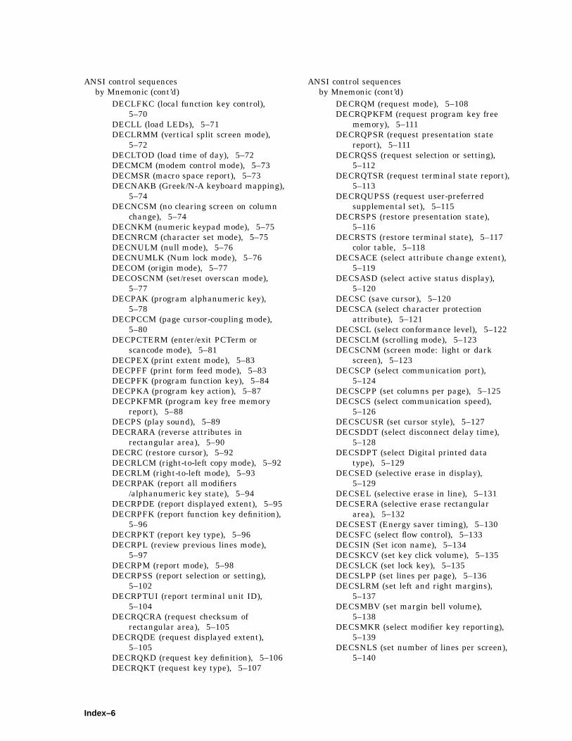
ANSI control sequencesby Mnemonic (cont’d)
DECLFKC (local function key control),5–70
DECLL (load LEDs), 5–71DECLRMM (vertical split screen mode),
5–72DECLTOD (load time of day), 5–72DECMCM (modem control mode), 5–73DECMSR (macro space report), 5–73DECNAKB (Greek/N-A keyboard mapping),
5–74DECNCSM (no clearing screen on column
change), 5–74DECNKM (numeric keypad mode), 5–75DECNRCM (character set mode), 5–75DECNULM (null mode), 5–76DECNUMLK (Num lock mode), 5–76DECOM (origin mode), 5–77DECOSCNM (set/reset overscan mode),
5–77DECPAK (program alphanumeric key),
5–78DECPCCM (page cursor-coupling mode),
5–80DECPCTERM (enter/exit PCTerm or
scancode mode), 5–81DECPEX (print extent mode), 5–83DECPFF (print form feed mode), 5–83DECPFK (program function key), 5–84DECPKA (program key action), 5–87DECPKFMR (program key free memory
report), 5–88DECPS (play sound), 5–89DECRARA (reverse attributes in
rectangular area), 5–90DECRC (restore cursor), 5–92DECRLCM (right-to-left copy mode), 5–92DECRLM (right-to-left mode), 5–93DECRPAK (report all modifiers
/alphanumeric key state), 5–94DECRPDE (report displayed extent), 5–95DECRPFK (report function key definition),
5–96DECRPKT (report key type), 5–96DECRPL (review previous lines mode),
5–97DECRPM (report mode), 5–98DECRPSS (report selection or setting),
5–102DECRPTUI (report terminal unit ID),
5–104DECRQCRA (request checksum of
rectangular area), 5–105DECRQDE (request displayed extent),
5–105DECRQKD (request key definition), 5–106DECRQKT (request key type), 5–107
ANSI control sequencesby Mnemonic (cont’d)
DECRQM (request mode), 5–108DECRQPKFM (request program key free
memory), 5–111DECRQPSR (request presentation state
report), 5–111DECRQSS (request selection or setting),
5–112DECRQTSR (request terminal state report),
5–113DECRQUPSS (request user-preferred
supplemental set), 5–115DECRSPS (restore presentation state),
5–116DECRSTS (restore terminal state), 5–117
color table, 5–118DECSACE (select attribute change extent),
5–119DECSASD (select active status display),
5–120DECSC (save cursor), 5–120DECSCA (select character protection
attribute), 5–121DECSCL (select conformance level), 5–122DECSCLM (scrolling mode), 5–123DECSCNM (screen mode: light or dark
screen), 5–123DECSCP (select communication port),
5–124DECSCPP (set columns per page), 5–125DECSCS (select communication speed),
5–126DECSCUSR (set cursor style), 5–127DECSDDT (select disconnect delay time),
5–128DECSDPT (select Digital printed data
type), 5–129DECSED (selective erase in display),
5–129DECSEL (selective erase in line), 5–131DECSERA (selective erase rectangular
area), 5–132DECSEST (Energy saver timing), 5–130DECSFC (select flow control), 5–133DECSIN (Set icon name), 5–134DECSKCV (set key click volume), 5–135DECSLCK (set lock key), 5–135DECSLPP (set lines per page), 5–136DECSLRM (set left and right margins),
5–137DECSMBV (set margin bell volume),
5–138DECSMKR (select modifier key reporting),
5–139DECSNLS (set number of lines per screen),
5–140
Index–6

ANSI control sequencesby Mnemonic (cont’d)
DECSPMA (Session page memoryallocation ), 5–141
DECSPP (set port parameters), 5–142DECSPPCS (select ProPrinter character
set), 5–143DECSPRTT (select printer type), 5–144DECSR (secure reset), 5–144DECSRC (secure reset confirmation),
5–146DECSSCLS (set scroll speed), 5–146DECSSDT (select status display (line)
type), 5–147DECSSL (select set-up language), 5–148DECST8C (set tab at every 8 columns),
5–149DECSTBM (set top and bottom margins),
5–149DECSTGLT (Select color look-up table),
5–151DECSTR (soft terminal reset), 5–150DECSTRL (set transmit rate limit), 5–152DECSTUI (set terminal unit ID), 5–153DECSWBV (set warning bell volume),
5–154DECSWL (single-width, single-height line),
5–154DECSWT (Set window title), 5–156DECSZS (select zero symbol), 5–155DECTABSR (tab stop report), 5–157DECTCEM (text cursor enable mode),
5–157DECTID (select terminal ID), 5–158DECTME (terminal mode emulation),
5–159DECTSR (terminal state report), 5–160
color table report, 5–161DECTST (invoke confidence test), 5–162DECUDK (user-defined keys), 5–163DECUS (Update session), 5–169DECVCCM (vertical cursor-coupling mode),
5–170DECXCPR (extended cursor position
report), 5–170, 5–174DECXRLM (transmit rate limiting), 5–171DL (delete line), 5–172DSR (data integrity report), 5–174DSR (device status report, keyboard),
5–175DSR (macro space report), 5–176DSR (operating status), 5–177DSR (printer port), 5–178DSR (user-defined keys), 5–179ECH (erase character), 5–179ED (erase in display), 5–180EL (erase in line), 5–180HPA (horizontal position absolute), 5–181
ANSI control sequencesby Mnemonic (cont’d)
HPR (horizontal position relative), 5–181HT (horizontal tab), 5–182HTS (horizontal tab set), 5–182HVP (horizontal and vertical position),
5–183ICH (insert character), 5–183IL (insert line), 5–184IND (index), 5–184IRM (insert/replace mode), 5–185KAM (keyboard action mode), 5–185LNM (line feed/new line mode), 5–186Locking shift (LS), 5–187LS0 (maps G0 into GL), 5–187LS1 (maps G1 into GL), 5–187LS1R (maps G1 into GR), 5–187LS2 (maps G2 into GL), 5–187LS2R (maps G2 into GR), 5–187LS3 (maps G3 into GL), 5–187LS3R (maps G3 into GR), 5–187MC (media copy), 5–188NEL (next line), 5–191NP (next page), 5–191PP (preceding page), 5–192PPA (page position absolute), 5–192PPB (page position backward), 5–193PPR (page position relative), 5–193RIS (reset to initial state), 5–194RM (reset mode), 5–195S7C1T (send 7-bit C1 control character to
host), 5–196S8C1T (send 8-bit C1 control characters),
5–196SCODFK (define function key), 6–7SCODFK (save cursor position (SCO)), 6–9SCODPCC (display PC character (SCO)),
6–8SCORC (SCO) (restore cursor), 6–9SCS (select character set), 5–197SD (pan up), 5–200SGR (select graphic rendition), 5–201SM (set mode), 5–206SRM (send/receive mode—local echo),
5–204SS2 (maps G2 into GL), 5–205SS3 (maps G3 into GL), 5–205SU (pan down), 5–207TBC (tab clear), 5–207VPA (vertical line position absolute), 5–208VPR (vertical position relative), 5–208
by Name, 4–16Alternate text color (DECATC), 4–18, 5–22Alternate text color blink mode
(DECATCBM), 4–19, 5–23Alternate text color underline mode
(DECATCUM), 4–19, 5–23ANSI conformance level, 4–36, 5–1
Index–7
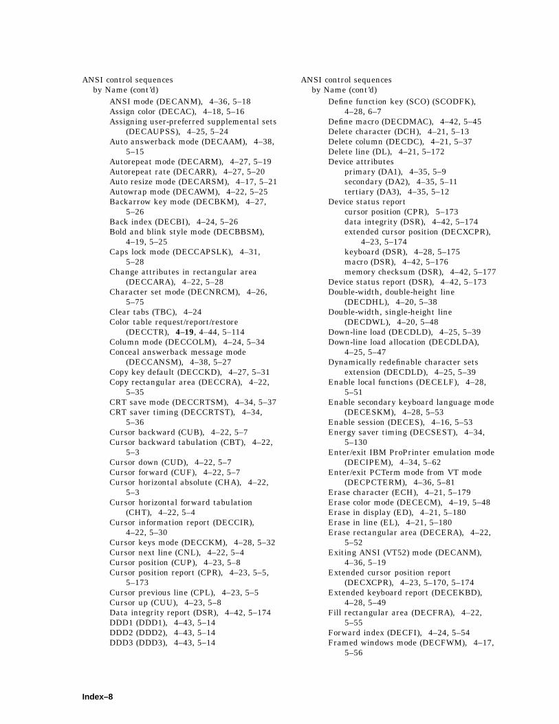
ANSI control sequencesby Name (cont’d)
ANSI mode (DECANM), 4–36, 5–18Assign color (DECAC), 4–18, 5–16Assigning user-preferred supplemental sets
(DECAUPSS), 4–25, 5–24Auto answerback mode (DECAAM), 4–38,
5–15Autorepeat mode (DECARM), 4–27, 5–19Autorepeat rate (DECARR), 4–27, 5–20Auto resize mode (DECARSM), 4–17, 5–21Autowrap mode (DECAWM), 4–22, 5–25Backarrow key mode (DECBKM), 4–27,
5–26Back index (DECBI), 4–24, 5–26Bold and blink style mode (DECBBSM),
4–19, 5–25Caps lock mode (DECCAPSLK), 4–31,
5–28Change attributes in rectangular area
(DECCARA), 4–22, 5–28Character set mode (DECNRCM), 4–26,
5–75Clear tabs (TBC), 4–24Color table request/report/restore
(DECCTR), 4–19, 4–44, 5–114Column mode (DECCOLM), 4–24, 5–34Conceal answerback message mode
(DECCANSM), 4–38, 5–27Copy key default (DECCKD), 4–27, 5–31Copy rectangular area (DECCRA), 4–22,
5–35CRT save mode (DECCRTSM), 4–34, 5–37CRT saver timing (DECCRTST), 4–34,
5–36Cursor backward (CUB), 4–22, 5–7Cursor backward tabulation (CBT), 4–22,
5–3Cursor down (CUD), 4–22, 5–7Cursor forward (CUF), 4–22, 5–7Cursor horizontal absolute (CHA), 4–22,
5–3Cursor horizontal forward tabulation
(CHT), 4–22, 5–4Cursor information report (DECCIR),
4–22, 5–30Cursor keys mode (DECCKM), 4–28, 5–32Cursor next line (CNL), 4–22, 5–4Cursor position (CUP), 4–23, 5–8Cursor position report (CPR), 4–23, 5–5,
5–173Cursor previous line (CPL), 4–23, 5–5Cursor up (CUU), 4–23, 5–8Data integrity report (DSR), 4–42, 5–174DDD1 (DDD1), 4–43, 5–14DDD2 (DDD2), 4–43, 5–14DDD3 (DDD3), 4–43, 5–14
ANSI control sequencesby Name (cont’d)
Define function key (SCO) (SCODFK),4–28, 6–7
Define macro (DECDMAC), 4–42, 5–45Delete character (DCH), 4–21, 5–13Delete column (DECDC), 4–21, 5–37Delete line (DL), 4–21, 5–172Device attributes
primary (DA1), 4–35, 5–9secondary (DA2), 4–35, 5–11tertiary (DA3), 4–35, 5–12
Device status reportcursor position (CPR), 5–173data integrity (DSR), 4–42, 5–174extended cursor position (DECXCPR),
4–23, 5–174keyboard (DSR), 4–28, 5–175macro (DSR), 4–42, 5–176memory checksum (DSR), 4–42, 5–177
Device status report (DSR), 4–42, 5–173Double-width, double-height line
(DECDHL), 4–20, 5–38Double-width, single-height line
(DECDWL), 4–20, 5–48Down-line load (DECDLD), 4–25, 5–39Down-line load allocation (DECDLDA),
4–25, 5–47Dynamically redefinable character sets
extension (DECDLD), 4–25, 5–39Enable local functions (DECELF), 4–28,
5–51Enable secondary keyboard language mode
(DECESKM), 4–28, 5–53Enable session (DECES), 4–16, 5–53Energy saver timing (DECSEST), 4–34,
5–130Enter/exit IBM ProPrinter emulation mode
(DECIPEM), 4–34, 5–62Enter/exit PCTerm mode from VT mode
(DECPCTERM), 4–36, 5–81Erase character (ECH), 4–21, 5–179Erase color mode (DECECM), 4–19, 5–48Erase in display (ED), 4–21, 5–180Erase in line (EL), 4–21, 5–180Erase rectangular area (DECERA), 4–22,
5–52Exiting ANSI (VT52) mode (DECANM),
4–36, 5–19Extended cursor position report
(DECXCPR), 4–23, 5–170, 5–174Extended keyboard report (DECEKBD),
4–28, 5–49Fill rectangular area (DECFRA), 4–22,
5–55Forward index (DECFI), 4–24, 5–54Framed windows mode (DECFWM), 4–17,
5–56
Index–8

ANSI control sequencesby Name (cont’d)
Greek/N-A keyboard mapping (DECNAKB),4–29, 5–74
Half-duplex mode (DECHDPXM), 4–41,5–56
Hebrew encoding mode (DECHEM), 4–28,5–57
Hebrew/N-A keyboard mapping(DECHEBM), 4–28, 5–58
Horizontal and vertical position (HVP),4–23, 5–183
Horizontal cursor coupling (DECHCCM),4–17, 5–100
Horizontal position absolute (HPA), 4–23,5–181
Horizontal position relative (HPR), 4–23,5–181
Horizontal tab (HT), 4–23, 5–182Horizontal tab set (HTS), 4–24, 5–182Host wake-up mode (DECHWUM), 4–34,
5–59Identify device (DECID), 4–35, 5–60Index (IND), 4–24, 5–184Insert character (ICH), 4–21, 5–183Insert column (DECIC), 4–21, 5–59Insert line (IL), 4–21, 5–184Insert/replace mode (IRM), 4–21, 5–185Invoke confidence test (DECTST), 4–38,
5–162Invoke macro (DECINVM), 4–42, 5–61Keyboard action mode (KAM), 4–28, 5–185Keyboard language selection (DECKBD),
4–28, 5–63Keyboard LEDs host indicator mode
(DECKLHIM), 4–31, 5–65Keyboard usage mode (DECKBUM), 4–29,
5–65Keypad application mode (DECKPAM),
4–28, 5–66Keypad numeric mode (DECKPNM), 4–29,
5–67Key position mode (DECKPM), 4–29, 5–66Left right margin mode (DECLRMM),
4–24, 5–72Line feed/new line mode (LNM), 4–23,
5–186Load answerback message (DECLANS),
4–38, 5–68Load banner message (DECLBAN), 4–38,
5–69Load LEDs (DECLL), 4–31, 5–71Load time of day (DECLTOD), 4–34, 5–72Local echo: send/receive mode (SRM),
4–38, 5–204Local function key control (DECLFKC),
4–29, 5–70Locking shift G0 (LS0), 4–2, 5–187
ANSI control sequencesby Name (cont’d)
Locking shift G1 (LS1), 4–2, 4–27, 5–187Locking shift G1 right (LS1R), 4–27, 5–187Locking shift G2 (LS2), 4–27, 5–187Locking shift G2 right (LS2R), 4–27, 5–187Locking shift G3 (LS3), 4–27, 5–187Locking shift G3 right (LS3R), 4–27, 5–187Macro space report (DECMSR), 4–42, 5–73Macro space report (DSR), 4–42, 5–176Media copy (MC), 4–33, 5–188Memory checksum (DECCKSR), 4–42,
5–33, 5–177Modem control mode (DECMCM), 4–41,
5–73National replacement character set mode
(DECNRCM), 4–26, 5–75Next line (NEL), 4–23, 5–191Next page (NP), 4–25, 5–191No clearing screen on column change
(DECNCSM), 4–24, 5–74Null mode (DECNULM), 4–41, 5–76Numeric keypad mode (DECNKM), 4–29,
5–75Num lock mode (DECNUMLK), 4–31, 5–76Operating status (DSR), 4–42, 5–177Origin mode (DECOM), 4–24, 5–77Overscan mode (DECOSCNM), 4–36, 5–77Page cursor-coupling mode (DECPCCM),
4–17, 5–80Page position absolute (PPA), 4–25, 5–192Page position backward (PPB), 4–25,
5–193Page position relative (PPR), 4–25, 5–193Pan down (SU), 4–17, 5–207Pan up (SD), 4–17, 5–200Play sound (DECPS), 4–18, 5–89Preceding page (PP), 4–25, 5–192Presentation state report (DECPSR), 4–42,
5–116Primary device attributes (DA1), 4–35, 5–9Printer port (DSR), 4–33, 5–178Print extent mode (DECPEX), 4–33, 5–83Print form feed mode (DECPFF), 4–33,
5–83Program alphanumeric key (DECPAK),
4–30, 5–78Program function key (DECPFK), 4–30,
5–84Program key action (DECPKA), 4–30, 5–87Program key free memory report
(DECPKFMR), 4–30, 5–88Report displayed extent (DECRPDE),
4–17, 5–95Report function key definition (DECRPFK),
4–31, 5–96Report key type (DECRPKT), 4–31, 5–96Report mode (DECRPM), 4–38, 4–42, 5–98
Index–9

ANSI control sequencesby Name (cont’d)
Report modifiers/alphanumeric key state(DECRPAK), 4–31, 5–94
Report selection or setting (DECRPSS),4–43, 5–102
Report terminal unit ID (DECRPTUI),4–35, 5–104
Request and report selection or setting(DECRQSS), 4–43, 5–112
Request checksum of rectangular area(DECRQCRA), 4–42, 5–105
Request displayed extent (DECRQDE),4–17, 5–105
Request key definition (DECRQKD), 4–31,5–106
Request key type (DECRQKT), 4–31,5–107
Request mode (DECRQM), 4–42, 5–108Request presentation state report
(DECRQPSR), 4–42, 5–111Request program key free memory
(DECRQPKFM), 4–30, 5–111Request terminal state report
(DECRQTSR), 4–43, 5–113Request user-preferred supplemental set
(DECRQUPSS), 4–26, 5–115Reset mode (RM), 4–38, 5–195Reset to initial state (RIS), 4–39, 5–194Restore cursor (DECRC), 4–23, 5–92Restore presentation state (DECRSPS),
4–44, 5–116Restore saved cursor (SCO) (SCORC),
4–23, 6–9Restore terminal state (DECRSTS), 4–44,
5–117color table, 5–118
Reverse attributes in rectangular area(DECRARA), 4–22, 5–90
Reverse index (RI), 4–24Review previous lines (DECRPL), 4–17,
5–97Right-to-left copy mode (DECRLCM), 4–23,
5–92Right-to-left mode (DECRLM), 4–23, 5–93Save cursor (DECSC), 4–23, 5–120Save cursor position (SCO) (SCOSC), 4–23,
6–9Screen alignment pattern (DECALN), 5–17Screen mode: light or dark screen
(DECSCNM), 4–20, 5–123Scrolling mode (DECSCLM), 4–24, 5–123Secondary device attributes (DA2), 4–35,
5–11Secure reset (DECSR), 4–39, 5–144Secure reset confirmation (DECSRC),
4–39, 5–146
ANSI control sequencesby Name (cont’d)
Select active status display (DECSASD),4–39, 5–120
Select attribute change extent (DECSACE),4–22, 5–119
Select character protection attribute(DECSCA), 4–21, 5–121
Select character set (SCS), 4–25, 5–197Select color look-up table (DECSTGLT),
4–19, 5–151Select columns per page (DECSCPP),
4–24, 5–125Select communication port (DECSCP),
4–39, 5–124Select communication speed (DECSCS),
4–39, 5–126Select conformance level (DECSCL), 4–36,
5–122Select Digital printed data type
(DECSDPT), 4–33, 5–129Select disconnect delay time (DECSDDT),
4–41, 5–128Select flow control (DECSFC), 4–41, 5–133Select graphic rendition (SGR), 4–20,
5–201Selective erase in display (DECSED),
4–21, 5–129Selective erase in line (DECSEL), 4–21,
5–131Selective erase rectangular area
(DECSERA), 4–22, 5–132Select modifier key reporting (DECSMKR),
4–31, 5–139Select printer type (DECSPRTT), 4–33,
5–144Select ProPrinter character set
(DECSPPCS), 4–33, 5–143Select set-up language (DECSSL), 4–34,
5–148Select status display (line) type
(DECSSDT), 4–39, 5–147Select terminal ID (DECTID), 4–35, 5–158Select zero symbol (DECSZS), 4–26, 5–155Send 7-bit C1 control character to host
(S7C1T), 4–27, 5–196Send 8-bit C1 control characters (S8C1T),
5–196Send 8-bit C1 control character to host
(S8C1T), 4–27Session page memory allocation
(DECSPMA), 4–16, 5–141Set cursor style (DECSCUSR), 4–23, 5–127Set icon name (DECSIN), 4–17, 5–134Set key click volume (DECSKCV), 4–31,
5–135Set left and right margins (DECSLRM),
4–24, 5–137
Index–10

ANSI control sequencesby Name (cont’d)
Set lines per page (DECSLPP), 4–24,5–136
Set lock key style (DECSLCK), 4–31,5–135
Set margin bell volume (DECSMBV), 4–18,5–138
Set mode (SM), 4–36, 5–206Set number of lines per screen (DECSNLS),
4–17, 5–140Set port parameters (DECSPP), 4–40,
5–142Set scroll speed (DECSSCLS), 4–24, 5–146Set tab at every 8 columns (DECST8C),
4–24, 5–149Set terminal unit ID (DECSTUI), 4–35,
5–153Set top and bottom margins (DECSTBM),
4–24, 5–149Set transmit rate limit (DECSTRL), 4–40,
5–152Set warning bell volume (DECSWBV),
4–18, 5–154Set window title (DECSWT), 4–17, 5–156Show control character mode (CRM), 4–27,
4–36, 5–6Single shift (SS), 4–27, 5–205Single shift 2 (SS2), 4–27, 5–205Single shift 3 (SS3), 4–27, 5–205Single-width line (DECSWL), 4–20, 5–154Soft terminal reset (DECSTR), 4–39,
5–150Switch between ASCII character and
Scancode mode (DECPCTERM), 4–36,5–81
Tab clear (TBC), 4–24, 5–207Tab stop report (DECTABSR), 4–44, 5–157Terminal identification (DECID), 4–35,
5–60Terminal mode emulation (DECTME),
4–36, 5–159Terminal state report
color table report (DECCTR), 4–44,5–114
Terminal state report (DECTSR), 4–44,5–160color table report, 5–161
Tertiary device attributes (DA3), 4–35,5–12
Text cursor enable mode (DECTCEM),4–23, 5–157
Transmit rate limiting (DECXRLM), 4–40,5–171
Update session (DECUS), 4–16, 5–169User-defined keys (DECUDK), 4–32, 5–163User-defined keys (DSR), 4–32, 5–179
ANSI control sequencesby Name (cont’d)
User-preferred supplemental set(DECRQUPSS), 4–26, 5–115
Vertical cursor-coupling mode (DECVCCM),4–17, 5–170
Vertical line position absolute (VPA), 4–23,5–208
Vertical position relative (VPR), 4–23,5–208
VT52 mode, 4–45Answerback
concealed, 2–51enabling, 2–50message, 2–50
Applicationcursor keys, 2–43keypad mode, 2–44
Arrow keys, 5–32ASCII
boarder display, 12–10character sets
defining, 13–1emulation mode, 3–7loading, 13–3
code table7-bit, 4–158-bit, 4–15
color mode, 2–32communications
answerback message, 12–1monitor mode, 12–1serial port, 12–2serial port control, 12–1
control functions, 11–1controlling cursor, 12–21defined, Glossary–1display attribute
control functions, 12–17editing control functions, 12–25emulation
features, 2–35menu, 2–35
emulations, 11–1enhanced mode, 11–2graphic characters, 12–36keyboard
processing, 12–5program key direction, 12–8redefinable keys, 12–9selections, 11–3
local functionsASCII code mode, C–10PC scancode mode, C–11
overscan on/off, 12–10page edit, 12–27page memory, 12–12PC keycodes
Index–11
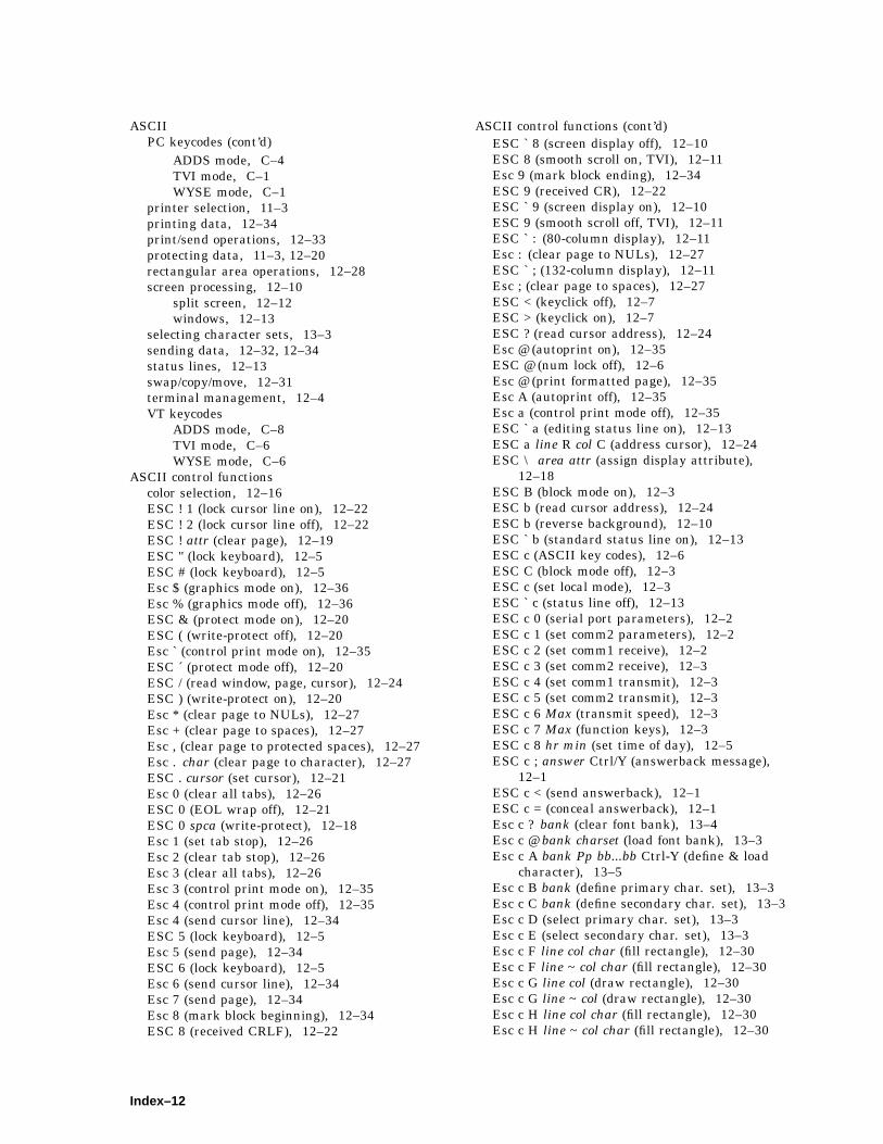
ASCIIPC keycodes (cont’d)
ADDS mode, C–4TVI mode, C–1WYSE mode, C–1
printer selection, 11–3printing data, 12–34print/send operations, 12–33protecting data, 11–3, 12–20rectangular area operations, 12–28screen processing, 12–10
split screen, 12–12windows, 12–13
selecting character sets, 13–3sending data, 12–32, 12–34status lines, 12–13swap/copy/move, 12–31terminal management, 12–4VT keycodes
ADDS mode, C–8TVI mode, C–6WYSE mode, C–6
ASCII control functionscolor selection, 12–16ESC ! 1 (lock cursor line on), 12–22ESC ! 2 (lock cursor line off), 12–22ESC ! attr (clear page), 12–19ESC " (lock keyboard), 12–5ESC # (lock keyboard), 12–5Esc $ (graphics mode on), 12–36Esc % (graphics mode off), 12–36ESC & (protect mode on), 12–20ESC ( (write-protect off), 12–20Esc ` (control print mode on), 12–35ESC ´ (protect mode off), 12–20ESC / (read window, page, cursor), 12–24ESC ) (write-protect on), 12–20Esc * (clear page to NULs), 12–27Esc + (clear page to spaces), 12–27Esc , (clear page to protected spaces), 12–27Esc . char (clear page to character), 12–27ESC . cursor (set cursor), 12–21Esc 0 (clear all tabs), 12–26ESC 0 (EOL wrap off), 12–21ESC 0 spca (write-protect), 12–18Esc 1 (set tab stop), 12–26Esc 2 (clear tab stop), 12–26Esc 3 (clear all tabs), 12–26Esc 3 (control print mode on), 12–35Esc 4 (control print mode off), 12–35Esc 4 (send cursor line), 12–34ESC 5 (lock keyboard), 12–5Esc 5 (send page), 12–34ESC 6 (lock keyboard), 12–5Esc 6 (send cursor line), 12–34Esc 7 (send page), 12–34Esc 8 (mark block beginning), 12–34ESC 8 (received CRLF), 12–22
ASCII control functions (cont’d)ESC ` 8 (screen display off), 12–10ESC 8 (smooth scroll on, TVI), 12–11Esc 9 (mark block ending), 12–34ESC 9 (received CR), 12–22ESC ` 9 (screen display on), 12–10ESC 9 (smooth scroll off, TVI), 12–11ESC ` : (80-column display), 12–11Esc : (clear page to NULs), 12–27ESC ` ; (132-column display), 12–11Esc ; (clear page to spaces), 12–27ESC < (keyclick off), 12–7ESC > (keyclick on), 12–7ESC ? (read cursor address), 12–24Esc @ (autoprint on), 12–35ESC @ (num lock off), 12–6Esc @ (print formatted page), 12–35Esc A (autoprint off), 12–35Esc a (control print mode off), 12–35ESC ` a (editing status line on), 12–13ESC a line R col C (address cursor), 12–24ESC \ area attr (assign display attribute),
12–18ESC B (block mode on), 12–3ESC b (read cursor address), 12–24ESC b (reverse background), 12–10ESC ` b (standard status line on), 12–13ESC c (ASCII key codes), 12–6ESC C (block mode off), 12–3ESC c (set local mode), 12–3ESC ` c (status line off), 12–13ESC c 0 (serial port parameters), 12–2ESC c 1 (set comm2 parameters), 12–2ESC c 2 (set comm1 receive), 12–2ESC c 3 (set comm2 receive), 12–3ESC c 4 (set comm1 transmit), 12–3ESC c 5 (set comm2 transmit), 12–3ESC c 6 Max (transmit speed), 12–3ESC c 7 Max (function keys), 12–3ESC c 8 hr min (set time of day), 12–5ESC c ; answer Ctrl/Y (answerback message),
12–1ESC c < (send answerback), 12–1ESC c = (conceal answerback), 12–1Esc c ? bank (clear font bank), 13–4Esc c @ bank charset (load font bank), 13–3Esc c A bank Pp bb...bb Ctrl-Y (define & load
character), 13–5Esc c B bank (define primary char. set), 13–3Esc c C bank (define secondary char. set), 13–3Esc c D (select primary char. set), 13–3Esc c E (select secondary char. set), 13–3Esc c F line col char (fill rectangle), 12–30Esc c F line ~ col char (fill rectangle), 12–30Esc c G line col (draw rectangle), 12–30Esc c G line ~ col (draw rectangle), 12–30Esc c H line col char (fill rectangle), 12–30Esc c H line ~ col char (fill rectangle), 12–30
Index–12

ASCII control functions (cont’d)Esc c I char (clear column to character), 12–28Esc c J (delete cursor column), 12–27Esc c K (clear position to NUL), 12–28Esc c L (clear to EOL with NULs), 12–28Esc c M (insert column of NULs), 12–27Esc c N width height (draw rectangle), 12–30Esc c O (clear to EOL with spaces), 12–28Esc c P (clear foreground to spaces), 12–28Esc c Q (clear foreground to NULs), 12–27Esc c R (clear foreground to spaces), 12–28Esc c S (clear foreground to NULs), 12–28ESC c T (set default all modes), 12–5ESC c \ tone (select bell), 12–7ESC c U (clear all key definitions), 12–8ESC ` cursor (set cursor), 12–21ESC c V (save Set-Up modes), 12–4ESC c W (save Set-Up modes), 12–4ESC c X (power on reset), 12–5ESC c ] Intensity (border display), 12–10Esc c ^ (swap, copy, move data), 12–30Esc d ! (aux mode on), 12–35Esc d # (control print mode on), 12–35Esc d $ (bidirectional mode off), 12–35Esc d % (bidirectional mode on), 12–35Esc d & (begin print), 12–34ESC d ( (cursor drag off), 12–13Esc d ` (begin print), 12–34ESC d / (EOL wrap on), 12–21ESC d (normal background), 12–10ESC D (request attribute under cursor), 12–19ESC d ) (cursor drag on), 12–13ESC d * (autopage off), 12–21ESC d + (autopage on), 12–21ESC d . (EOL wrap off), 12–21ESC D F (set full-duplex), 12–3ESC D H (set half-duplex), 12–3ESC d line R col C (address cursor), 12–24Esc d Sp (aux mode off), 12–35ESC d { (blank attribute), 12–16ESC d | (reverse on), 12–16Esc e ! (answerback on), 12–1Esc e " (page edit off), 12–27Esc e # (page edit on), 12–27ESC e $ (keyclick off), 12–7ESC e % (keyclick on), 12–7ESC e & (caps lock on), 12–6ESC e ( (set 24 data lines), 12–11ESC e ´ (caps lock off), 12–6Esc E (insert line of spaces), 12–27ESC e - (key repeat on), 12–5ESC e (user line off), 12–17ESC e / (width-change-clear on), 12–12ESC e ) (set 25 data lines), 12–11ESC e * (set 42 data lines), 12–11ESC e + (set 43 data lines), 12–11ESC e , (key repeat off), 12–5ESC e . (width-change-clear off), 12–12
ASCII control functions (cont’d)ESC e 0 (char attribute mode off), 12–18ESC e 1 (char attribute mode on), 12–18ESC e 2 (page attribute mode on), 12–18ESC e 3 (line attribute mode on), 12–18ESC e 4 (received CR), 12–22ESC e 5 (received CRLF), 12–22ESC e 6 (ACK mode off), 12–1ESC e 7 (ACK mode on), 12–1ESC e 8 (assign serial ports), 12–1ESC e 9 (s1=comm2), 12–1ESC e > (character cell size), 12–11ESC e ? (character cell size), 12–11ESC e A (num lock on), 12–6ESC e B (scroll lock off), 12–6ESC e C (scroll lock on), 12–6ESC e D (DEL mode off), 12–22ESC e E (DEL mode on), 12–22ESC e H (ASCII key codes), 12–6ESC e I (PC scan codes), 12–6ESC e L (bell off), 12–7ESC e M (bell on), 12–7Esc e N (font loading off), 13–4Esc e O (font loading on), 13–4ESC e P (screen saver off), 12–10ESC e Q (screen saver on), 12–10ESC e R (ignore null characters), 12–1ESC e S (accept null characters), 12–2ESC e Sp (answerback off), 12–1ESC e T (lock key), 12–6ESC e U (lock key), 12–6ESC e V (lock key), 12–6ESC e | (intensity off), 12–16ESC e } (intensity on), 12–16ESC f (clear label line), 12–15ESC F (fill page H’s), 12–12ESC F CR (clear computer message), 12–14ESC f CR (clear label line), 12–15ESC F message CR (display computer message),
12–14ESC f text CR (display computer message),
12–14ESC g (user line on), 12–17ESC G Attr (assign character attribute), 12–17ESC G LineAttr (assign line attribute), 12–19ESC ` H (lock cursor line on), 12–22ESC H (PC scan codes), 12–6ESC h (user line off), 12–17Esc H char (display character), 12–36Esc H Ctrl-B (graphics mode on), 12–36Esc H Ctrl-C (graphics mode off), 12–36ESC h page (address cursor), 12–24Esc I (back tab cursor), 12–26ESC ` I (lock cursor line off), 12–22Esc i (tab cursor), 12–26ESC J (activate other window), 12–13ESC j (cursor up), 12–23ESC J (display page), 12–12
Index–13
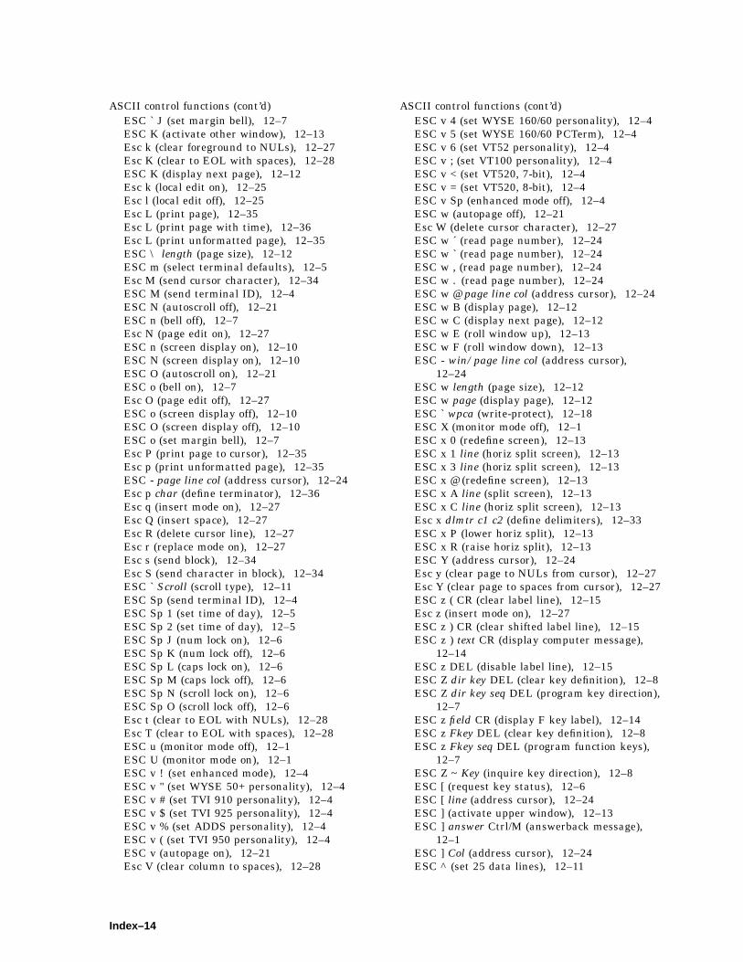
ASCII control functions (cont’d)ESC ` J (set margin bell), 12–7ESC K (activate other window), 12–13Esc k (clear foreground to NULs), 12–27Esc K (clear to EOL with spaces), 12–28ESC K (display next page), 12–12Esc k (local edit on), 12–25Esc l (local edit off), 12–25Esc L (print page), 12–35Esc L (print page with time), 12–36Esc L (print unformatted page), 12–35ESC \ length (page size), 12–12ESC m (select terminal defaults), 12–5Esc M (send cursor character), 12–34ESC M (send terminal ID), 12–4ESC N (autoscroll off), 12–21ESC n (bell off), 12–7Esc N (page edit on), 12–27ESC n (screen display on), 12–10ESC N (screen display on), 12–10ESC O (autoscroll on), 12–21ESC o (bell on), 12–7Esc O (page edit off), 12–27ESC o (screen display off), 12–10ESC O (screen display off), 12–10ESC o (set margin bell), 12–7Esc P (print page to cursor), 12–35Esc p (print unformatted page), 12–35ESC - page line col (address cursor), 12–24Esc p char (define terminator), 12–36Esc q (insert mode on), 12–27Esc Q (insert space), 12–27Esc R (delete cursor line), 12–27Esc r (replace mode on), 12–27Esc s (send block), 12–34Esc S (send character in block), 12–34ESC ` Scroll (scroll type), 12–11ESC Sp (send terminal ID), 12–4ESC Sp 1 (set time of day), 12–5ESC Sp 2 (set time of day), 12–5ESC Sp J (num lock on), 12–6ESC Sp K (num lock off), 12–6ESC Sp L (caps lock on), 12–6ESC Sp M (caps lock off), 12–6ESC Sp N (scroll lock on), 12–6ESC Sp O (scroll lock off), 12–6Esc t (clear to EOL with NULs), 12–28Esc T (clear to EOL with spaces), 12–28ESC u (monitor mode off), 12–1ESC U (monitor mode on), 12–1ESC v ! (set enhanced mode), 12–4ESC v " (set WYSE 50+ personality), 12–4ESC v # (set TVI 910 personality), 12–4ESC v $ (set TVI 925 personality), 12–4ESC v % (set ADDS personality), 12–4ESC v ( (set TVI 950 personality), 12–4ESC v (autopage on), 12–21Esc V (clear column to spaces), 12–28
ASCII control functions (cont’d)ESC v 4 (set WYSE 160/60 personality), 12–4ESC v 5 (set WYSE 160/60 PCTerm), 12–4ESC v 6 (set VT52 personality), 12–4ESC v ; (set VT100 personality), 12–4ESC v < (set VT520, 7-bit), 12–4ESC v = (set VT520, 8-bit), 12–4ESC v Sp (enhanced mode off), 12–4ESC w (autopage off), 12–21Esc W (delete cursor character), 12–27ESC w ´ (read page number), 12–24ESC w ` (read page number), 12–24ESC w , (read page number), 12–24ESC w . (read page number), 12–24ESC w @ page line col (address cursor), 12–24ESC w B (display page), 12–12ESC w C (display next page), 12–12ESC w E (roll window up), 12–13ESC w F (roll window down), 12–13ESC - win/page line col (address cursor),
12–24ESC w length (page size), 12–12ESC w page (display page), 12–12ESC ` wpca (write-protect), 12–18ESC X (monitor mode off), 12–1ESC x 0 (redefine screen), 12–13ESC x 1 line (horiz split screen), 12–13ESC x 3 line (horiz split screen), 12–13ESC x @ (redefine screen), 12–13ESC x A line (split screen), 12–13ESC x C line (horiz split screen), 12–13Esc x dlmtr c1 c2 (define delimiters), 12–33ESC x P (lower horiz split), 12–13ESC x R (raise horiz split), 12–13ESC Y (address cursor), 12–24Esc y (clear page to NULs from cursor), 12–27Esc Y (clear page to spaces from cursor), 12–27ESC z ( CR (clear label line), 12–15Esc z (insert mode on), 12–27ESC z ) CR (clear shifted label line), 12–15ESC z ) text CR (display computer message),
12–14ESC z DEL (disable label line), 12–15ESC Z dir key DEL (clear key definition), 12–8ESC Z dir key seq DEL (program key direction),
12–7ESC z field CR (display F key label), 12–14ESC z Fkey DEL (clear key definition), 12–8ESC z Fkey seq DEL (program function keys),
12–7ESC Z ~ Key (inquire key direction), 12–8ESC [ (request key status), 12–6ESC [ line (address cursor), 12–24ESC ] (activate upper window), 12–13ESC ] answer Ctrl/M (answerback message),
12–1ESC ] Col (address cursor), 12–24ESC ^ (set 25 data lines), 12–11
Index–14

ASCII control functions (cont’d)ESC ^ 0 (normal background), 12–10ESC ^ 1 (reverse background), 12–10ESC _ (set 43 data lines), 12–11ESC _ Col (address cursor), 12–24ESC { (cursor home), 12–24ESC { (set half-duplex), 12–3ESC { baud stop parity word (serial port
parameters), 12–2ESC | Fkey dir seq Ctrl-Y (program key
direction), 12–8ESC } (activate lower window), 12–13ESC } (set full-duplex), 12–3ESC } baud stop parity word (serial port
parameters), 12–2ESC ~ ! (set enhanced mode), 12–4ESC ~ " (set WYSE 50+ personality), 12–4ESC ~ # (set TVI 910 personality), 12–4ESC ~ $ (set TVI 925 personality), 12–4ESC ~ % (set ADDS personality), 12–4ESC ~ ( (set TVI 950 personality), 12–4ESC ~ (EOL wrap on), 12–21ESC ~ 4 (set WYSE 160/60 personality), 12–4ESC ~ 5 (set WYSE 160/60 PCTerm), 12–4ESC ~ 6 (set VT52 personality), 12–4ESC ~ ; (set VT100 personality), 12–4ESC ~ < (set VT520, 7-bit), 12–4ESC ~ = (set VT520, 8-bit), 12–4ESC ~ Sp (enhanced mode off), 12–4
Assign colors, 2–28Audible attributes
control functions, 4–18Austrian
PC keyboard, B–3VT keyboard, A–2
Autoanswerback, 2–50repeat rate, 2–43resize, 2–20wrap, 2–23
Automatic font loading, 13–4Autorepeating keys, 5–19Autowrapping text, 5–25
BBanks, 13–3Banner message, 2–11, 3–1
power on, 2–3Baud rate
menu, 2–48receive speed, 2–48
BelgianPC keyboard, B–4VT keyboard, A–3
Bellmargin, 2–42visible, 2–43
Bell (cont’d)warning, 2–25, 2–42
7-bit and 8-bit environments, 4–107-bit ASCII code table, 4–158-bit ASCII code table, 4–157-bit code extension technique, 4–97-bit NRCS character sets, 7–2Blinking, 5–201Bold and blink style, 2–32Bold display, 5–201Break key, 9–15British/U.K.
PC keyboard, B–5VT keyboard, A–4
CC0 control characters, 4–1, 4–15C1 control characters, 4–1, 4–9, 4–15Calculator, 2–11
feature, 3–1enabling, 3–2
CanadianEnglish
PC keyboard, B–6VT keyboard, A–4
FrenchPC keyboard, B–7VT keyboard, A–5
CAN character, 4–9Carrier detect, 9–6Character
delete, 7–3NULL, 7–3space, 7–3
Character attributes, 5–201Character encoding, 4–15Characters
ASCII graphic, 12–36Character set codes, 5–198Character sets, 2–11, 7–1
ASCII control functions, 13–1ASCII emulation mode, 3–77-bit NRCS, 2–34, 7–2control characters, 7–3default
PC, 2–34VT, 2–34
designing, 7–6downloaded, 7–5downloading, 7–13mappings
ANSI, 7–4PCTerm mode, 7–5
PCTerm mode, 7–2, 7–4printer, 2–55
DEC/ISO, 2–56PC, 2–56
Index–15
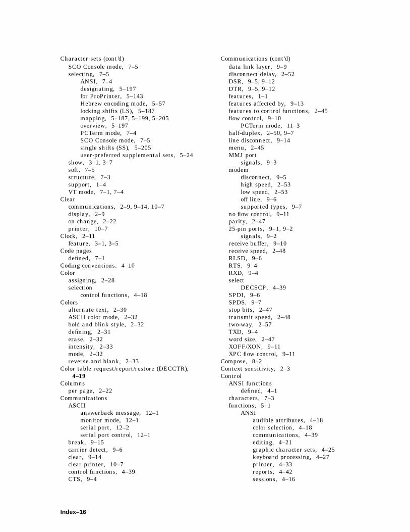
Character sets (cont’d)SCO Console mode, 7–5selecting, 7–5
ANSI, 7–4designating, 5–197for ProPrinter, 5–143Hebrew encoding mode, 5–57locking shifts (LS), 5–187mapping, 5–187, 5–199, 5–205overview, 5–197PCTerm mode, 7–4SCO Console mode, 7–5single shifts (SS), 5–205user-preferred supplemental sets, 5–24
show, 3–1, 3–7soft, 7–5structure, 7–3support, 1–4VT mode, 7–1, 7–4
Clearcommunications, 2–9, 9–14, 10–7display, 2–9on change, 2–22printer, 10–7
Clock, 2–11feature, 3–1, 3–5
Code pagesdefined, 7–1
Coding conventions, 4–10Color
assigning, 2–28selection
control functions, 4–18Colors
alternate text, 2–30ASCII color mode, 2–32bold and blink style, 2–32defining, 2–31erase, 2–32intensity, 2–33mode, 2–32reverse and blank, 2–33
Color table request/report/restore (DECCTR),4–19
Columnsper page, 2–22
CommunicationsASCII
answerback message, 12–1monitor mode, 12–1serial port, 12–2serial port control, 12–1
break, 9–15carrier detect, 9–6clear, 9–14clear printer, 10–7control functions, 4–39CTS, 9–4
Communications (cont’d)data link layer, 9–9disconnect delay, 2–52DSR, 9–5, 9–12DTR, 9–5, 9–12features, 1–1features affected by, 9–13features to control functions, 2–45flow control, 9–10
PCTerm mode, 11–3half-duplex, 2–50, 9–7line disconnect, 9–14menu, 2–45MMJ port
signals, 9–3modem
disconnect, 9–5high speed, 2–53low speed, 2–53off line, 9–6supported types, 9–7
no flow control, 9–11parity, 2–4725-pin ports, 9–1, 9–2
signals, 9–2receive buffer, 9–10receive speed, 2–48RLSD, 9–6RTS, 9–4RXD, 9–4select
DECSCP, 4–39SPDI, 9–6SPDS, 9–7stop bits, 2–47transmit speed, 2–48two-way, 2–57TXD, 9–4word size, 2–47XOFF/XON, 9–11XPC flow control, 9–11
Compose, 8–2Context sensitivity, 2–3Control
ANSI functionsdefined, 4–1
characters, 7–3functions, 5–1
ANSIaudible attributes, 4–18color selection, 4–18communications, 4–39editing, 4–21graphic character sets, 4–25keyboard processing, 4–27printer, 4–33reports, 4–42sessions, 4–16
Index–16
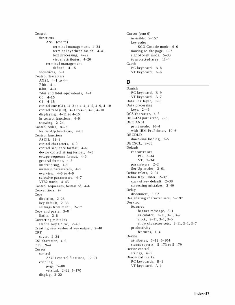
Controlfunctions
ANSI (cont’d)terminal management, 4–34terminal synchronization, 4–41text processing, 4–22visual attributes, 4–20
terminal managementdefined, 4–15
sequences, 5–1Control characters
ANSI, 4–1 to 4–47-bit, 4–18-bit, 4–37-bit and 8-bit equivalents, 4–4C0, 4–15C1, 4–15control one (C1), 4–3 to 4–4, 4–5, 4–9, 4–10control zero (C0), 4–1 to 4–3, 4–5, 4–10displaying, 4–11 to 4–15in control functions, 4–9showing, 2–24
Control codes, 8–28for Set-Up functions, 2–61
Control functionsASCII, 11–1control characters, 4–9control sequence format, 4–6device control string format, 4–8escape sequence format, 4–6general format, 4–5interrupting, 4–9numeric parameters, 4–7overview, 4–5 to 4–9selective parameters, 4–7VT52 mode, 4–45
Control sequences, format of, 4–6Conventions, ivCopy
direction, 2–23key default, 2–38settings from menu, 2–17
Copy and paste, 3–8limits, 3–8
Correcting mistakesDefine Key Editor, 2–40
Creating new keyboard key output, 2–40CRT
saver, 2–24CSI character, 4–6CTS, 9–4Cursor
controlASCII control functions, 12–21
couplingpage, 5–80vertical, 2–22, 5–170
display, 2–22
Cursor (cont’d)invisible, 5–157key codes
SCO Console mode, 6–6moving on the page, 5–7right-to-left mode, 5–93to protected area, 11–4
CzechPC keyboard, B–8VT keyboard, A–6
DDanish
PC keyboard, B–9VT keyboard, A–7
Data link layer, 9–9Data processing
keys, 2–43DCS character, 4–8DEC-423 port error, 2–3DEC ANSI
print mode, 10–4with IBM ProPrinter, 10–6
DECDLDdown-line loading, 7–5
DECSCL, 2–33Default
character setPC, 2–34VT, 2–34
parameters, 2–2Set-Up modes, 2–61
Define colors, 2–31Define Key Editor, 2–37
copy of key default, 2–38correcting mistakes, 2–40
Delaydisconnect, 2–52
Designating character sets, 5–197Desktop
featuresbanner message, 3–1calculator, 2–11, 3–1, 3–2clock, 2–11, 3–1, 3–5show character sets, 2–11, 3–1, 3–7
productivityfeatures, 1–4
Deviceattributes, 5–12, 5–104status reports, 5–173 to 5–179
Device controlstrings, 4–8
Diacritical marksPC keyboards, B–1VT keyboard, A–1
Index–17

Dim menu items, 2–3Dim video, 2–3Disconnect delay, 2–52Display
attributecontrol functions, 12–17
capabilities, 1–3menu, 2–19
Display C0 controls as PC characters (SCO)(SCODPCC), 4–27
Displaying control characters, 4–11 to 4–15Display menu
control functions, 2–19Down-line loading
allocation, 5–47character sets, 7–5, 7–13DECDLD, 7–5
DRCSdefined, 1–6
DSR, 9–5DTR, 2–49, 9–5DTR/DSR, 10–2
flow control, 2–48, 2–49, 9–12printer, 2–57threshold, 2–49
Duplexhalf, 2–50
DutchPC keyboard, B–10VT keyboard, A–8
EEcho, local, 2–50Editing
ASCII control functions, 12–25character protection attribute, 5–121, 5–131control functions, 4–21delete
character, 5–13column, 5–37line, 5–172
erasecharacter, 5–179in display, 5–180in line, 5–180
insertcharacter, 5–183column, 5–59line, 5–184
keypad key codesSCO Console mode, 6–6
selective erase in display, 5–129EIA communications
See Communications
Embedded emulation mode, 12–15Emulation
mode, 2–33Emulations
ASCII, 11–1Energy saver, 2–24Enhanced mode, 11–2Entering Set-Up, 2–1Erase color, 2–32Erasing data
ASCII control functions, 12–28Ergonomics, 1–4Error
character, 4–2correcting UDK, 2–40
Error messagesDEC-423 port error, 2–3keyboard error, 2–3NVR error, 2–3parallel port error, 2–3ROM cartridge error, 2–3RS-232 port data error, 2–3self-test, 2–3
Escape sequences, format of, 4–6VT52 mode, 4–45
ESC character, 4–6, 4–9Exit Set-Up, 2–9
FFeatures
affected by communications, 9–13printer port, 10–1
Final characterANSI index, E–1
FinnishPC keyboard, B–11VT keyboard, A–9
FlemishVT keyboard, A–10
Flow control, 9–10printer, 10–1threshold, 2–49
Fontdesigning, 13–5loading, 13–4sizes, 1–4
Framed windows, 2–26French
PC keyboard, B–12VT keyboard, A–3
French-CanadianPC keyboard, B–7VT keyboard, A–5
Full-duplexmode, 9–1
Index–18

Function keyscodes
SCO Console mode, 6–2rate limit, 2–49
GGerman
PC keyboard, B–3VT keyboard, A–2
Glossary, Glossary–1Graphic
character sets, 7–17-bit NRCS, 7–2control characters, 7–3mappings
ANSI, 7–4PCTerm mode, 7–5
PCTerm mode, 7–2, 7–4selecting
ANSI, 7–4PCTerm mode, 7–4SCO Console mode, 7–5
soft, 7–5structure, 7–3VT mode, 7–1, 7–4
Graphic character setscontrol functions, 4–25
GreekPC keyboard, B–13VT keyboard, A–11
Greek/N-A keyboardmapping, 5–74
HHalf-duplex
communications, 2–50mode, 9–1signals, 9–7
Hardware flow control, 1–1Hebrew
PC keyboard, B–14VT keyboard, A–12
Hebrew/N-A keyboardmapping, 5–58
Hidden emulation mode, 12–15Hungarian
PC keyboard, B–15VT keyboard, A–13
IIBM ProPrinter
mode, 10–5with DEC ANSI, 10–6
Icon name, 2–14ID to host, 2–34Ignore missing keyboard, 2–44Ignore null characters, 2–50Inserting and deleting data, 5–183, 5–185, 5–191,
5–195Insert/replace mode, 5–185In-use table, 5–197Invisible attribute, 5–201Italian
PC keyboard, B–16VT keyboard, A–14
KKeyboard
arrow keys, 5–32ASCII
local functionsPC scancode mode, C–11
processing, 12–5program key direction, 12–8redefinable keys, 12–9terminal, 11–3
autorepeating keys, 5–19autowrap mode, 5–25control codes and keystrokes, 8–28control functions, 2–36enabling local functions, 5–51encoding menu item, 2–43error, 2–3extended keyboard report, 5–49features, 1–2, 1–3<x function, 5–26‘‘hot’’ keys, Glossary–2indicator line, 2–6language for Set-Up, 2–37layouts
PC keyboards, B–2VT keyboards, A–1
line feed/new line mode, 5–186local-function key control, 5–70local functions
ASCII code mode, C–10locking keyboard, 5–185menu, 2–36numeric keypad, 5–67, 5–75PC
Austrian, B–3Belgian, B–4British/U.K., B–5Canadian-English, B–6Canadian-French, B–7Czech, B–8Danish, B–9Dutch, B–10Finnish, B–11French, B–12
Index–19

KeyboardPC (cont’d)
German, B–3Greek, B–13Hebrew, B–14Hungarian, B–15Italian, B–16Latin American, B–17North American, B–6Norwegian, B–18Polish, B–19Portuguese, B–20Romanian, B–21Russian, B–22SCS, B–23Slovak, B–24Spanish, B–25Swedish, B–26Swiss-French, B–27Swiss-German, B–28Turkish, B–29
PC legend data, B–2processing control functions, 4–27quick start summary, 3–8saving key definitions, 2–42scan code, defined, Glossary–2select modifier key reporting, 5–139typewriter or data processing keys, 5–65unlocking keyboard, 5–185user-defined keys, 5–163VT
Austrian, A–2Belgian, A–3British/U.K., A–4Canadian, A–4Canadian-French, A–5Czech, A–6Danish, A–7Dutch, A–8Finnish, A–9Flemish, A–10French, A–3German, A–2Greek, A–11Hebrew, A–12Hungarian, A–13Italian, A–14North American, A–4Norwegian, A–15Polish, A–16Portuguese, A–17Romanian, A–18Russian, A–19SCS, A–20Slovak, A–21Spanish, A–22Swedish, A–23Swiss-French, A–24
KeyboardVT (cont’d)
Swiss-German, A–25Turkish-F, A–26Turkish-Q, A–27
VT legend data, A–1VT vs. PC, 1–2, 8–1
Keyboard control functions, 5–163Keyboard mapping
Greek/N-A, 5–74Hebrew/N-A, 5–58
Keyclick, 2–42Keycodes
PC keyboardADDS mode, C–4TVI mode, C–1WYSE mode, C–1
VT keyboardADDS mode, C–8TVI mode, C–6WYSE mode, C–6
Key editor, 2–37Keypad mode
application, 2–44Keys
application cursor, 2–43data processing, 2–43
LLanguage
Set-Up, 2–2Language, Set-Up, 2–37Latin American
PC keyboard, B–17Lines
per page, 2–20per screen, 2–20
Localcontroller mode, 2–8echo, 2–8, 2–50Function keys
SCO Console mode, 6–2mode, 2–8
Lockcaps, 2–42keyboard, 5–185key definitions, 2–42user preferences, 2–23
Locking-shift (LS) control functions, 5–187
MMacro commands, 5–45
defining, 5–45Main keypad key codes
SCO Console mode, 6–3
Index–20
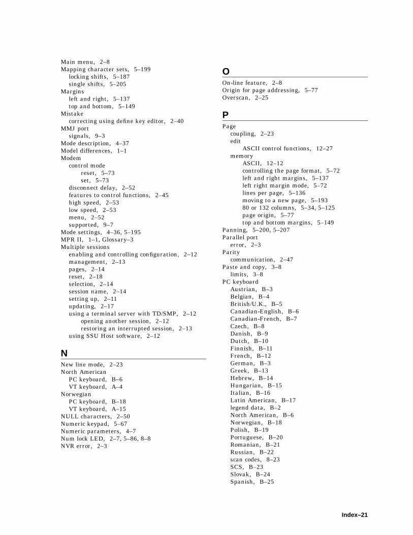
Main menu, 2–8Mapping character sets, 5–199
locking shifts, 5–187single shifts, 5–205
Marginsleft and right, 5–137top and bottom, 5–149
Mistakecorrecting using define key editor, 2–40
MMJ portsignals, 9–3
Mode description, 4–37Model differences, 1–1Modem
control modereset, 5–73set, 5–73
disconnect delay, 2–52features to control functions, 2–45high speed, 2–53low speed, 2–53menu, 2–52supported, 9–7
Mode settings, 4–36, 5–195MPR II, 1–1, Glossary–3Multiple sessions
enabling and controlling configuration, 2–12management, 2–13pages, 2–14reset, 2–18selection, 2–14session name, 2–14setting up, 2–11updating, 2–17using a terminal server with TD/SMP, 2–12
opening another session, 2–12restoring an interrupted session, 2–13
using SSU Host software, 2–12
NNew line mode, 2–23North American
PC keyboard, B–6VT keyboard, A–4
NorwegianPC keyboard, B–18VT keyboard, A–15
NULL characters, 2–50Numeric keypad, 5–67Numeric parameters, 4–7Num lock LED, 2–7, 5–86, 8–8NVR error, 2–3
OOn-line feature, 2–8Origin for page addressing, 5–77Overscan, 2–25
PPage
coupling, 2–23edit
ASCII control functions, 12–27memory
ASCII, 12–12controlling the page format, 5–72left and right margins, 5–137left right margin mode, 5–72lines per page, 5–136moving to a new page, 5–19380 or 132 columns, 5–34, 5–125page origin, 5–77top and bottom margins, 5–149
Panning, 5–200, 5–207Parallel port
error, 2–3Parity
communication, 2–47Paste and copy, 3–8
limits, 3–8PC keyboard
Austrian, B–3Belgian, B–4British/U.K., B–5Canadian-English, B–6Canadian-French, B–7Czech, B–8Danish, B–9Dutch, B–10Finnish, B–11French, B–12German, B–3Greek, B–13Hebrew, B–14Hungarian, B–15Italian, B–16Latin American, B–17legend data, B–2North American, B–6Norwegian, B–18Polish, B–19Portuguese, B–20Romanian, B–21Russian, B–22scan codes, 8–23SCS, B–23Slovak, B–24Spanish, B–25
Index–21
PC keyboard (cont’d)Swedish, B–26Swiss-French, B–27Swiss-German, B–28Turkish, B–29
PCTermgraphic character sets, 7–2mode
communications flow control, 11–3on US keyboard, 13–1
scan codesEPC keyboards, 8–23VT keyboards, 8–27
selecting character sets, 7–425-pin port, 9–1, 9–2
signals, 9–2Polish
PC keyboard, B–19VT keyboard, A–16
PortuguesePC keyboard, B–20VT keyboard, A–17
Power-onbanner message, 2–3, 2–11
Presentation state reports, 5–116Print
datatransmitting, 10–4
modesaffecting print operations, 10–3
operations, 10–4ASCII, 12–33
Printeraborting operations, 10–7character sets, 2–55
DEC/ISO, 2–56PC, 2–56
control functions, 4–33controller mode, 10–4data transmission, 10–5features to control functions, 2–55flashes on screen, 10–7ignore null characters, 2–50menu, 2–54parity, 2–58port
control functions, 5–83DSR/DTR, 10–2features, 1–3, 10–1flow control, 10–1, 10–3parallel, 10–2
signals, 10–2select, 2–54serial, 10–1
printextent, 2–56mode, 2–54speed, 2–56
Printerprint (cont’d)
terminator, 2–56receive flow control, 2–57receive speed, 2–48same as receive, 2–58stalls, 10–7stop bits, 2–47, 2–58suspending operations, 10–7transmit flow control, 2–57transmit speed, 2–48type, 2–55word size, 2–57
Printer port control functions, 5–83Printing
dataASCII control functions, 12–34
form feeds, 5–83full screen or scrolling region, 5–83
ProPrinterenter mode, 5–62exit mode, 5–62selecting
character set, 5–143code pages, 5–143printer type, 5–144
Protecting dataASCII control functions, 12–20description, 11–3
RRecall
key definitions, 2–42Receive
buffercommunications, 9–10
flow control, 2–49Receive speed, 2–48Rectangular area operations
changing character attributes, 5–90 to 5–91copying, 5–35defined, 12–28erasing, 5–52, 5–132filling, 5–55
Redefining keysASCII, 12–9
Repeat keys, 2–43Reports
control functions, 4–42cursor information report, 5–30cursor position report, 5–173data integrity report, 5–174extended cursor position report, 5–174macro space report, 5–176memory checksum, 5–177operating status, 5–177primary device attributes (DA1), 5–9
Index–22
Reports (cont’d)printer port, 5–178report mode, 5–98report selection or setting, 5–102request mode, 5–108reset mode, 5–195restore presentation state, 5–116restore terminal state, 5–117
color table, 5–118secondary device attributes (DA2), 5–11set mode, 5–206tab stop report, 5–157terminal state, 5–160
color table report, 5–161terminal unit ID, 5–104tertiary device attributes (DA3), 5–12user-defined keys, 5–179
Resettingmodem control mode, 5–73session, 2–10terminal
secure reset, 5–144soft reset, 2–10
Resetting the terminal, 5–207clearing tabs, 5–207reset to initial state, 5–194secure reset confirmation, 5–146
Restorefactory defaults, 2–10, 2–18settings, 2–9
for all, 2–16Restoring an interrupted session, 2–13Reverse and blank attributes, 2–33Reverse video, 5–201Review lines of text, 2–21Review previous lines, 2–21
buffer, 2–21Right-to-left mode
cursor, 5–93RI—Reverse index, 4–4RLSD, 9–6Romanian
PC keyboard, B–21VT keyboard, A–18
ROM cartridgeerror, 2–3
RS-232 port data error, 2–3RTS, 9–4Russian
PC keyboard, B–22VT keyboard, A–19
RXD, 9–4
SSave
key definitions, 2–42settings, 2–9
for all, 2–16Scan codes
sent in PCTerm modeEPC keyboards, 8–23VT keyboards, 8–27
SCO Consolecursor key codes, 6–6editing keypad key codes, 6–6emulation, 6–1emulation mode, 5–159function key
codes, 6–2local function keys, 6–2main keypad key codes, 6–3scancodes, 5–81SCODFK (define function key), 6–7SCODPCC (display PC characters), 6–8SCORC (restore saved cursor position), 6–9SCOSC (save cursor position), 6–9selecting character sets, 7–5with ASCII keycodes, 6–1with Scancode keycodes, 6–1
SCO control sequencesby Control Function
CSI s (SCOSC), 6–9CSI u (SCORC), 6–9ESC Q Fn String (SCODFK), 6–7ESC xx (SCODPCC), 6–8
by MnemonicSCODFK (define function key), 6–7SCODPCC (display PC characters ), 6–8SCORC (restore saved cursor position),
6–9SCOSC (save current cursor position), 6–9
by NameDefine function key (SCODFK), 6–7Display PC characters (SCODPCC), 6–8Restore saved cursor position (SCORC),
6–9Save current cursor position (SCOSC), 6–9
Screenalignment, 2–27background, 2–22display control functions, 5–147 to 5–148processing
ASCII, 12–10saver, 2–24
Scrollingjump, 2–22mode, 2–22rate, 2–22smooth, 2–22
Index–23

SCSPC keyboard, B–23VT keyboard, A–20
Selectcolor mode, 2–32
Selectingcharacter sets
ASCII control functions, 13–3Selective parameters, 4–7Self-test
error messages, 2–3Sending data
ASCII, 12–32ASCII control functions, 12–34
Sessionmenu, 2–13
Sessions, 1–6control functions, 4–16management, 4–16multiple, 2–11
enabling and controlling configuration,2–12
management, 2–13pages, 2–14selection, 2–14using a terminal server with TD/SMP,
2–12opening another session, 2–12restoring an interrupted session, 2–13
using SSU Host software, 2–12reset, 2–18session name, 2–14switching, 3–8updating, 2–17
Setting modem control mode, 5–73Set-Up, 2–1
actions menu, 2–7, 2–9alternate text colors, 2–30ASCII color mode, 2–32ASCII emulation menu, 2–35assign colors, 2–28auto repeat rate, 2–43auto resize, 2–20auto wrap, 2–23banner message, 2–117-bit NRCS, 2–34bold and blink style, 2–32calculator, 2–11caps lock, 2–42clear communications, 2–9clear display, 2–9clock, 2–11columns per page, 2–22communications
auto answerback, 2–50Fkey rate limit, 2–49half-duplex, 2–50ignore null characters, 2–50
Set-Upcommunications (cont’d)
local echo, 2–50modem menu, 2–52receive flow control, 2–49receive speed, 2–48select sessions, 2–46stop bits, 2–47transmit flow control, 2–48transmit rate limit, 2–49transmit speed, 2–48word size, 2–47
communications menu, 2–45context sensitivity, 2–3control codes to set features, 2–61copy settings from menu, 2–17CRT saver, 2–24cursor coupling
vertical, 2–22cursor display, 2–22default character set
PC, 2–34VT, 2–34
defaults, 2–61define colors, 2–31define key editor, 2–37
copy key default, 2–38correcting a mistake, 2–40creating a new function, 2–39creating a new key definition, 2–40user-defined keys, 2–41
desktop featuresbanner message, 3–1calculator, 3–1, 3–2clock, 3–1, 3–5show character sets, 3–1, 3–7
dim menu items, 2–3display menu, 2–19effects of entering, 2–2emulation mode, 2–33energy saver, 2–24entering, 2–1erase color, 2–32exiting, 2–9framed windows, 2–25keyboard encoding, 2–43keyboard language, 2–37keyboard menu, 2–36keyclick, 2–42languages, 2–2lines per page, 2–20lines per screen, 2–20lock key definitions, 2–42lock out, 2–1lock user preferences, 2–23main menu, 2–7, 2–8margin bell, 2–42modem
Index–24

Set-Upmodem (cont’d)
disconnect delay, 2–52enable modem control, 2–52speed, 2–53
modem menu, 2–52multiple sessions, 2–11
management, 2–13pages, 2–14reset, 2–18selection, 2–14session name, 2–14updating, 2–17using a terminal server with TD/SMP,
2–12opening another session, 2–12restoring an interrupted session, 2–13
using SSU Host software, 2–12new line mode, 2–23page coupling, 2–23power-on settings, 2–2printer
character sets, 2–55flow control, 2–57ignore null characters, 2–50mode, 2–54parity, 2–58port select, 2–54print extent, 2–56print terminator, 2–56speed, 2–56stop bits, 2–58type, 2–55word size, 2–57
printer menu, 2–54recall key definitions, 2–42reset this session, 2–10resetting and restoring defaults, 2–18restore factory defaults, 2–10, 2–18restore settings, 2–9restore settings for all, 2–16reverse and blank, 2–33review previous lines, 2–21save key definitions, 2–42save settings, 2–9save settings for all, 2–16screen background, 2–22scrolling, 2–22select color mode, 2–32session menu, 2–13show character sets, 2–11show control characters, 2–24soft character sets, 2–16status messages, 2–5summary line, 2–5tabs, 2–58terminal ID to host, 2–34terminal type, 2–33
Set-Up (cont’d)transmit 7-bit controls, 2–34warning bell, 2–25, 2–42writing direction, 2–23zero symbol, 2–23
Showcharacter sets, 2–11control characters, 2–24, 4–11
C0 control characters, 4–15C1 control characters, 4–15
Single-shift (SS) commands, 5–205Slovak
PC keyboard, B–24VT keyboard, A–21
Soft character setclearing, 7–16example, 7–15
Soft character sets, 7–5 to 7–16coding, 7–9designating, 7–14designing, 7–6downloading, 7–13
Soft key mapping, Glossary–3Soft terminal reset, 2–10Software flow control, 1–1Sound
notes available, 2–60types of, 2–59
SpanishPC keyboard, B–25VT keyboard, A–22
SPDI, 9–6SPDS, 9–7Split screen, 12–12Status
display, 2–22lines
ASCII control functions, 12–13messages, 2–5
Sticky keys, 2–6See Accessibility aids
Stop bits, 2–47SUB character, 4–9Supplemental character sets
See User-preferred supplemental character setsSuspending
printer operations, 10–7Swedish
PC keyboard, B–26VT keyboard, A–23
SwissFrench
PC keyboard, B–27VT keyboard, A–24
GermanPC keyboard, B–28VT keyboard, A–25
Index–25

TTabs
dialog box, 2–59setting, 2–58
TabulationASCII control functions, 12–26
TerminalID, 1–6ID to host, 2–34management
ASCII, 12–4type menu, 2–33
Terminal managementcontrol functions, 4–34
defined, 4–15Terminal state reports, 5–117
color table, 5–118Terminal synchronization
control functions, 4–41Testing the terminal
screen alignment pattern, 5–17Text
capabilities, 1–3processing, 4–22
Transmit7-bit controls, 2–34flow control, 2–48rate limit, 2–49speed, 2–48
Transmitting print data, 10–4Turkish-F
VT keyboard, A–26Turkish-Q
PC keyboard, B–29VT keyboard, A–27
Two-way communications, 2–57TXD, 9–4
UUDK
correcting mistakes, 2–40Underlining, 5–201Unlocking keyboard, 5–185Use of VT420 keyboards, 1–6User-defined keys, 2–41, 5–163User-preferred supplemental character sets, 5–24
VVertical
coupling, 2–22Visible bell, 2–43Visual attributes
control functions, 4–20
VT52 modeescape sequences, 4–45
VT keyboardAustrian, A–2Belgian, A–3British/U.K., A–4Canadian, A–4Canadian-French, A–5Czech, A–6Danish, A–7Dutch, A–8Finnish, A–9Flemish, A–10French, A–3German, A–2Greek, A–11Hebrew, A–12Hungarian, A–13Italian, A–14legend data, A–1North American, A–4Norwegian, A–15Polish, A–16Portuguese, A–17Romanian, A–18Russian, A–19scan codes, 8–27SCS, A–20Slovak, A–21Spanish, A–22Swedish, A–23Swiss-French, A–24Swiss-German, A–25Turkish-F, A–26Turkish-Q, A–27
VT keyboards, A–1
WWarning bell, 2–25Window
adjustment, 3–8framed, 2–25
Windowing, 2–25two windows, 2–26
WindowsASCII control functions, 12–13
Word size, 2–47Writing
direction, 2–23WYSE Enhanced mode, 13–1
Index–26
XXON/XOFF, 9–11
description, 11–3XPC flow control, 9–11
ZZero symbol, 2–23
Index–27