
VT100 Display Controller BV4511 - ByVac
10
ByVac Product Specification VT100 Display Controller BV4511 ©ByVac Page 1 of 10 BV4511 VT100 Display Controller Product specification Aug 2009 V0.a
Transcript of VT100 Display Controller BV4511 - ByVac

ByVac Product Specification
VT100 Display Controller BV4511
©ByVac Page 1 of 10
BV4511 VT100 Display Controller Product specification Aug 2009 V0.a

ByVac Product Specification
VT100 Display Controller BV4511
©ByVac Page 2 of 10
Contents 1. Introduction ................................................................................................................3 2. Features .....................................................................................................................3 3. Physical Specification ...................................................................................................3
3.1. Serial Interface .......................................................................................................3 3.2. Connection Examples ...............................................................................................4 3.3. Multiple Displays .....................................................................................................4 3.4. LCD Display Interface...............................................................................................5
4. Using .........................................................................................................................5 5. Automatic Baud Rate....................................................................................................6 6. VT100 ........................................................................................................................6
6.1. Implemented Escape Codes ......................................................................................6 7. VT100 Commands........................................................................................................7
7.1. esc[<line>;<col>H (Move Cursor).............................................................................7 7.2. esc[<num>A Move Cursor Up ...................................................................................8 7.3. esc[numf Set Foreground Colour ...............................................................................8 7.4. esc{<row>;<col>P (Place Pixel) ..............................................................................8 7.5. esc{<row>;<col>p (Move to Pixel) ..........................................................................8 7.6. esc{y0 x0 y1 x1L Draw Line......................................................................................8 7.7. esc{y0 x0 y1 x1B Draws a Box..................................................................................8 7.8. esc{y0 x0 y1 x1F Draws a Filled Box..........................................................................8 7.9. esc{ y0 x0 <dia>C Draws a Circle .............................................................................8 7.10. Graphics Considerations ...........................................................................................8 7.11. esc[?29 numa Fine Tune Baud Rates..........................................................................9 7.12. esc[?27D Write EEPROM Defaults ..............................................................................9 7.13. esc[?27D Sign On....................................................................................................9
8. Hardware Reset...........................................................................................................9 9. Quirks ......................................................................................................................10
9.1. Baud rate .............................................................................................................10 9.2. Circles..................................................................................................................10

ByVac Product Specification
VT100 Display Controller BV4511
©ByVac Page 3 of 10
Rev Change August 2009
Preliminary
October 2009
The Hardware reset pins were indicated wrongly this is now corrected
October 2010
BV4511 is now sold as controller without display
1. Introduction The BV4511 is a 128 x 64 pixel LCD display controller that provides serial input. This then acts as a mini display terminal accepting text, graphics and pictures using a subset of VT100 commands and ordinary text. It can be connected to a standard RS232 port (with conversion), Microcontroller UART or A BV103 USB to serial converter for direct connectivity to a PC. The display is primarily intended for a replacement to the usual LCD type displays. It can be used for Microcontroller applications or directly with a PC, displaying system information for example. Up to 8 lines of text 20 characters wide can be displayed. For programming examples see www.asi.byvac.com
2. Features • Serial Input • Automatic Baud rate from a selection
of rates up to 112500 • Multiple displays on same Com port • VT100 subset • Two Fonts normal and bold • Graphics – line drawing, boxes and
circles • User definable sign on screen • Supply voltage from 5V DC • Current: 40mA @ 5V, 8.5mA @5V
with back light off. • Size 52 x 21 x 10mm
The Controller is intended to drive the KS0108 type LCD Graphic display.
3. Physical Specification The BC4511 is intended to fit at the back of the display and so it is important that the physical pads match the display it is intended for
Block Diagram
3.1. Serial Interface
Serial Connector The serial connector is a 2x5 pin at the back of the device. Pin 1 is marked with 1. The odd pins are in a horizontal row above the even pins. Pin Function Function Pin 1 RX nDD 2 3 TX 4 5 +5V 6 7 89 Gnd nRTS 10 This bVT100 serial connector will mate directly with the BV103. For this device the TX line is not used as the display does not output any information, it is a read only device.

ByVac Product Specification
VT100 Display Controller BV4511
©ByVac Page 4 of 10
This interface relies on hardware handshaking, without it the device will work but it will not be able to perform at its maximum speed. See below in the nRTS section. RX This is the serial receive and expects signals 0 to 5V. The idle state is high (5V).
This shows a typical serial signal at 115,200 Baud. The byte sent is 1 and so the first signal is the start bit followed by a pulse high that represents 1. The scale is 2V per square. The latter part is 2 stop bits which are low and so cannot be differentiated form the 0’s that are being transmitted. It follows a standard RS232 type protocol with 1 start bit and 1 or 2 stop bits so connection to just about any asynchronous serial interface will do provided the signalling is 0-5V TX This signal is not used for this device as it is read a read only device. +5V Is the main power supply for the display which should be capable of providing 40mA if the back light is going to be used. nRTS (output) Hardware handshaking is an essential part of this interface. Without it the display will work but delays must be included after each character otherwise information will be lost. This line is held low (0V) by the display when it is ready to accept data, it will put this line high when it is busy, the transmitter should monitor this and only send characters when the line is low. This signal is normally connected to the CTS line of the transmitting device. nDD This is called the Display Disable and if left disconnected the line is pulled high by an internal pull up resistor, thus enabling the device. If the line is taken low then the display becomes disconnected from the serial interface. This is so that more than one device can be connected to the same serial bus. If the line is pulled low, the displays UART will be disabled and the RTS line will also be disconnected, effectively removing the display from the circuitry. This will take a finite time to accomplish (approximately 10uS) and so
this must be taken into account when switching between displays. Important: This line must be high when the device is switched on otherwise the EEPROM settings will revert to the factory defaults. If it si not going to be used then leave it disconnected.
3.2. Connection Examples
Connection to the BV101-4 and BV103 is very straight forward BV103 will directly plug into the BV4511. The BV103 provides both 3V3 and 5V on a selector, 5V should be selected.
Connection to the older type BV101-4 requires the hardware handshake to be connected. The CTS line of the BV101-4 is pin 2 of the side connector. This should go to pin 10 on the BV4511.
For connection to an RS232 port a buffer such as the MAX232 is required. The diagram shows a partial example with the signal and power connections. Depending on the type the MAX232 will also require some other external components.
3.3. Multiple Displays As previously mentioned it is possible to control more than one display by using the nDD signal line. This is similar to Chip Select except it does the opposite, when asserted (taken low) it deselects the device.
ByVac Product Specification
VT100 Display Controller BV4511
©ByVac Page 5 of 10
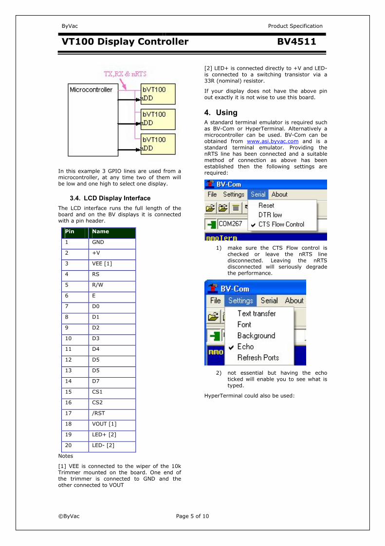
In this example 3 GPIO lines are used from a microcontroller, at any time two of them will be low and one high to select one display.
3.4. LCD Display Interface The LCD interface runs the full length of the board and on the BV displays it is connected with a pin header.
Pin Name 1 GND 2 +V 3 VEE [1] 4 RS 5 R/W 6 E7 D0 8 D1 9 D2 10 D3 11 D4 12 D5 13 D5 14 D7 15 CS1 16 CS2 17 /RST 18 VOUT [1] 19 LED+ [2] 20 LED- [2]
Notes [1] VEE is connected to the wiper of the 10k Trimmer mounted on the board. One end of the trimmer is connected to GND and the other connected to VOUT
[2] LED+ is connected directly to +V and LED- is connected to a switching transistor via a 33R (nominal) resistor. If your display does not have the above pin out exactly it is not wise to use this board.
4. Using A standard terminal emulator is required such as BV-Com or HyperTerminal. Alternatively a microcontroller can be used. BV-Com can be obtained from www.asi.byvac.com and is a standard terminal emulator. Providing the nRTS line has been connected and a suitable method of connection as above has been established then the following settings are required:
1) make sure the CTS Flow control is checked or leave the nRTS line disconnected. Leaving the nRTS disconnected will seriously degrade the performance.
2) not essential but having the echo ticked will enable you to see what is typed.
HyperTerminal could also be used:

ByVac Product Specification
VT100 Display Controller BV4511
©ByVac Page 6 of 10
The above settings should work.
5. Automatic Baud Rate When the display is first switched on or has been reset with the appropriate VT100 command, the FIRST byte that MUST be sent is a Carriage Return (enter on the keyboard) this is byte value 13 or 0x0d in hex. The device will be able to establish the Baud rate from this single byte. Until this happens the device cannot be used. The Baud rate is determined form the following standard rates and will select one of these based on that first byte: 9600, 14400, 19200, 38400, 57600, 115200 The transmitting terminal must be set at one of those rates. In some situations the transmitter may not be accurate and give unreliable results on the higher baud rates. If this is the case the rates can be fine tuned. See the appropriate commands in the VT100 section
6. VT100 Once connected the display simply accepts text and duplicates it to the screen. Connecting a terminal emulator such as BV_Comm or HyperTerminal will enable anything typed into it to be duplicated on the display. To control the display, for example clearing the screen or placing letters in a certain location escape codes are used. An escape code is the escape key (byte 27) followed by various symbols, numbers and letters. Escape codes have been used for many years and were a feature of the early terminals. The most popular set of codes is called VT100 used by old DEC terminals. It was so popular that it
became a standard way to control terminal screens before the days of the PC. This display wherever possible uses the most common of these codes.
6.1. Implemented Escape Codes In the table the left hand column indicates: S is the VT100 standard P is partially standard N is non-standard Grayed out cells are not implemented on this device. S Code Bytes
decimal Description
Y LF 10 Line feed (10) Y CR 13 Carriage return
(13) Y BS 8 Back space (8) P esc(1 27,40,
49 Normal font
P esc(2 27,40, 50
Bold font
Y esc[?25I 27,91, 63,50,53,73
Hide cursor
Y esc[?25h 27,91, 63,50,53,104
Show cursor
N esc[?26I 27,91, 63,50, 54,73
Back light off
N esc[?26h 27,91, 63,50, 54,104
Back light on
N esc[?29 numa
see text Paragraph 7.11
Writes to EEPROM Baud rate fine tune: 38,400
N esc[?29 numb
see text Paragraph 7.11
Writes to EEPROM Baud rate fine tune: 57,600
N esc[?29 numc
see text Paragraph 7.11
Writes to EEPROM Baud rate fine tune: 115,200
N esc[8h 27,91, 56,104
Clear screen on bottom scroll (default)
N esc[8l 27,91, 56,73
Don’t clear screen [1]

ByVac Product Specification
VT100 Display Controller BV4511
©ByVac Page 7 of 10
N esc[?27D see text Paragraph 7.12
Write defaults to EEPROM
N esc[?27M see text Paragraph
Write sign on message to EEPROM
N esc[?30a 27,91, 63,51,48,97
Displays current status of display
Y esc[2J 27,63, 50,74
Clear screen using default background colour
N esc[3J 27,63, 51,74
Clear screen and reset all defaults
Y esc[<line>;<col>H
see text Paragraph 7.1
Move cursor to line and column [2]
Y esc[<num>A
see text Paragraph 7.2
Move cursor up one or more lines, <num> is optional
Y esc[<num>B
see text Paragraph 7.2
Move cursor down one or more lines, <num> is optional
Y esc[<num>C
see text Paragraph 7.2
Move cursor right one or more lines, <num> is optional
Y esc[<num>D
see text Paragraph 7.2
Move cursor left one or more lines, <num> is optional
Y escD 27,68 Move cursor down one line
Y escM 27,77 Move cursor up one line
Y esc[H 27,63, 72
Cursor home
P escc 27,99 Reset device N escb 27,98 Load bitmap N esc[numf see text
Paragraph 7.3
Sets foreground colour
N esc[numb Sets background colour
N esc[numV Sets contrast Y esc[K 27,63,
75 Clear line from cursor right
Y esc[1K 27,63, 49,75
Clear line from cursor left
Y esc[2K 27,63, 50,75
Clear entire line
N esc{<row>;<col>P
see text Paragraph 7.4
Places single pixel in current foreground colour
N esc{<row>;<col>p
see text Paragraph 7.5
Places pixel without showing it.
N esc{y0 x0 y1 x1L
see text Paragraph 7.6
Draws a line in the current foreground colour
N esc{y0 x0 y1 x1B
see text Paragraph 7.7
Draws a box in the current foreground colour
N esc{y0 x0 y1 x1F
see text Paragraph 7.8
Draws a filled box in the current foreground colour
N esc{ y0 x0 <dia>C
see text Paragraph 7.9
Draws a circle in the current forground colour
Notes [1] the letter following number in the escape code is lower case L
7. VT100 Commands All VT100 commands begin with escape, this is byte decimal 27 or hex 0x1b. The commands are interpreted immediately as they are typed in, there is no need to follow with CR or LF. Most of the time the command is determined by the final character, for example turning the back light on and off is exactly the same command except for the final character. Some commands are obvious and so will not be covered in detail. The less obvious commands are below.
7.1. esc[<line>;<col>H (Move Cursor)
This command is used to position the cursor on the display. The cursor whether visible or not determines where the next character is placed. Line is a number beginning at 0 and ending with one less then the number of lines available on the display. On an 8 line display the first line would be 0 and the last line would be 7. Column is the number of characters across the display, also starting at 0. It is calculated using the current font so some unexpected results could occur if the font has

ByVac Product Specification
VT100 Display Controller BV4511
©ByVac Page 8 of 10
been changed within the line. Either the line or column values can be left out. For the BV4511 the line and column values are: Line 0-7 Column 0-20 (depends on font) esc[0;5H Moves the cursor to the first line 6th character along esc[4;H Moves the cursor to line 5 retaining the current horizontal (column) position esc[;3H Moves the cursor to the 4th character position on the current line. See also esc{<row>;<col>p
7.2. esc[<num>A Move Cursor Up Also commands: esc[<num>B (down) esc[<num>C (right) esc[<num>D (left) Moves the cursor by one or more character spaces or lines. The character space (horizontal) is calculated form the current font. The number specifies how many character spaces to move and is optional, if left out a default of 1 is taken so: esc[1B is the same as esc[B
7.3. esc[numf Set Foreground Colour
On this display, this command sets both the foreground and background colours. The number value is either 0 or 1. Zero is the default and depends on the display as to whether the pixels are on or off. The effect of changing this is to invert the displayed information. Only actions after this command will be effected, previous entries will remain the same. This is a global setting and so will effect all other commands.
7.4. esc{<row>;<col>P (Place Pixel)
Places a single pixel drawn in the foreground colour at the position given. The row is the vertical height and the column is the horizontal position, accepted values are: row 0-63 column 0-127 Where 0,0 is the top left corner of the screen. To erase a pixel the change the foreground colour and use this command.
7.5. esc{<row>;<col>p (Move to Pixel)
The functionality of this command is similar to that of 7.4 except that it does not draw a pixel. It is mainly used for positioning and can be used to position text in the horizontal direction more accurately than the ‘H’ command. Specifying a row value within the character height will place text on that line. For example a row height of 0-7 will place the text on the first line, 8-15 the second line etc. The column value however will place the text horizontally on a pixel, this can be very useful for centering text titles or producing special effects by overlapping characters.
7.6. esc{y0 x0 y1 x1L Draw Line This will draw a line in any direction, the starting co-ordinates are given by y0,x0 and the ending co-ordinates by y1,x1. Y is the vertical co-ordinate and can have a value between 0 and 63. Zero is the top of the screen and 63 is the bottom. X is the horizontal direction and can have values between 0 and 127. O being the left most position and 127 being the right most.
7.7. esc{y0 x0 y1 x1B Draws a Box Draws a box, y0,x0 specify the top left corner of the box and y1,x1 specify the bottom right corner of the box. y1 must be greater then y0 and x1 must be greater then x0 otherwise unexpected results may occur. Y is the vertical co-ordinate and can have a value between 0 and 63. Zero is the top of the screen and 63 is the bottom. X is the horizontal direction and can have values between 0 and 127
7.8. esc{y0 x0 y1 x1F Draws a Filled Box
This is the same as 7.8 except the box is filled.
7.9. esc{ y0 x0 <dia>C Draws a Circle
Draws a circle, the centre given by y0,x0.
7.10. Graphics Considerations
It is up to the user not to specify co-ordinates that are outside the available range. Some checking is done and can be tolerated, trial an error will give the best results. The circle drawing is not perfect as an attempt is made to fit into the pixels available. A very small diameter will produce a diamond rather then a circle.

ByVac Product Specification
VT100 Display Controller BV4511
©ByVac Page 9 of 10
7.11. esc[?29 numa Fine Tune Baud Rates
At higher Baud rates some hosts are not particularly accurate in the Baud rate timing. To prevent any mismatch between the host and this device the Baud rates can be fine tuned using this and its sister commands: esc[?29 numa Fine tune 38,400 (51) esc[?29 numb Fine tune 57,600 (34) esc[?29 numc Fine tune 115,200 (16) The number in the brackets gives an accurate timing for the respective Baud rates, the lower the number the faster the baud rate. The command writes a number to the EEPROM for use with the Autobaud detect. As detection only occurs at reset, the effect on any of these commands will not be seen until reset. As an example suppose that the Baud rate of 115,200 gave unreliable results, the first try may be to slow it down and so these commands could be used: esc[?29 17c (writes 17 to EEPROM) escc (resets device) Set the host to 115,200 and press enter (CR), see if the results are any better.
7.12. esc[?27D Write EEPROM Defaults
Some settings can be stored to EEPROM so that these become the default at start up. This command will write the settings to the EEPROM which will be used when the device is reset. The following shows which vales can be saved. Command Name esc[numf Foreground colour esc(num Current font esc[8h/l Clear screen on bottom
scrol The values are programmed using the ‘Write defaults to EEPROM command (esc[?27D).
7.13. esc[?27D Sign On The sign on message is stored in EEPROM and there are approximately 220 bytes available for a message that will be displayed at start up or reset. This message is displayed BEFORE the autobaud detect. The message is made up of exactly the same escape codes and text that would form a normal display. The only difference is that it must end with CTRL z (^z or byte value 26) esc[?27D … message body and formatting codes
^z The above is what the message should look like in order to be written to EEPROM. The final ^z is important. This command if not properly used may cause the display to stop working, if this happens then a Hardware reset is required.
8. Hardware Reset The purpose of the hardware reset is to reset the EEPROM back to a known position so that the display will work correctly. The procedure is:
1) Disconnect the display from power 2) Connect the reset pins together. This
is pins 3 & 4 on the FR connector, see the picture in section 3
3) Apply power 4) Disconnect power
The display will now work correctly. The hardware reset can be found by looking for 5 holes in a line, one of the holes will have a square copper pad and marked with either 1 or FR or both. Connect this copper pad to the third pad with a bit of wire. See the picture at the beginning of this text. The reset will have a simple text massage similar to:
The splash screen that is normally seen is in fact applied during testing and is this macro: �[?27M �(2�[1;5H�[3fByVac �{18;12pwww.byvac.com �(1 �{26;27pVT100 Dsiplay �[6;0H See datasheet to �[Bchange this sign-on �
[2J Sign on Message �[B

ByVac Product Specification
VT100 Display Controller BV4511
©ByVac Page 10 of 10
has now been written �[B to EEPROM The � is the escape characters, this can be copied and pasted into notepad and sent to the display but the HW handshaking must be enabled. see www.asi.byvac.com for other macro’s and articles.
9. Quirks 9.1. Baud rate
When using the highest Baud rate of 115200 it has been found that the transmitting device has to be highly accurate. This has been found
to be not always the case with some microcontrollers. The symptoms are intermittent garbled text. The cure is to reduce the Baud rate or fine tune the receiving rate using the EEPROM settings.
9.2. Circles Drawing of circles is not perfect. A radius of 4 or smaller circles will become a square. Should the circle go out of the drawing area then pixels may appear on non related parts of the screen.


