VT System Smart HIL Testing - ukintpress-conferences.com · ©2010. Vector Informatik GmbH. All...
17
© 2010. Vector Informatik GmbH. All rights reserved. Any distribution or copying is subject to prior written approval by Vector. V1.0 2010-06-04 VT System Smart HIL Testing
Transcript of VT System Smart HIL Testing - ukintpress-conferences.com · ©2010. Vector Informatik GmbH. All...
© 2010. Vector Informatik GmbH. All rights reserved. Any distribution or copying is subject to prior written approval by Vector.
V1.0 2010-06-04
VT SystemSmart HIL Testing
2
© 2010. Vector Informatik GmbH. All rights reserved. Any distribution or copying is subject to prior written approval by Vector.
Slide:
Agenda
Summary and Outlook
Testing a Door Control Unit
ECU Testing>
3
© 2010. Vector Informatik GmbH. All rights reserved. Any distribution or copying is subject to prior written approval by Vector.
Slide:
ECU Testing
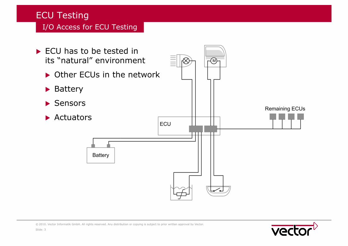
� ECU has to be tested in its “natural” environment
� Other ECUs in the network
� Battery
� Sensors
� Actuators
I/O Access for ECU Testing
M
Battery
ECU
Remaining ECUs
4
© 2010. Vector Informatik GmbH. All rights reserved. Any distribution or copying is subject to prior written approval by Vector.
Slide:
ECU Testing
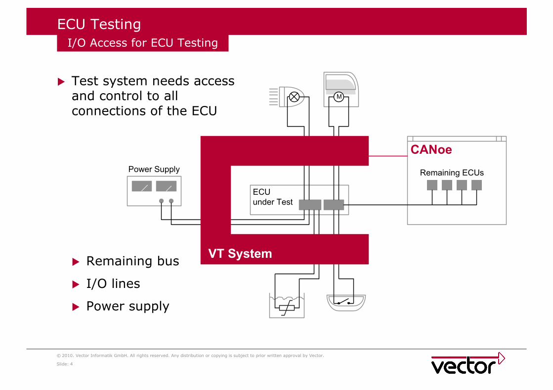
� Test system needs access and control to all connections of the ECU
� Remaining bus
� I/O lines
� Power supply
I/O Access for ECU Testing
M
Power Supply
CANoe
ECU
under Test
Remaining ECUs
VT System

5
© 2010. Vector Informatik GmbH. All rights reserved. Any distribution or copying is subject to prior written approval by Vector.
Slide:
ECU Testing
� Highly integrated modules to cover the complete testing requirements of an input or output channel
� Stimulation
� Measurement
� Fault injection
� Minimal cabling, no additional hardware
� Focus on test case development
� Modular and scalable
� From developer‘s desk to dedicated HIL systems
� Electric characteristics suited to automotive requirements
� Connection to CANoe via EtherCAT®
� Fulfills real-time requirements
� Connection via standard Ethernet interface
VT System Concept
EtherCAT® is registered trademark and patented technology, licensed by Beckhoff Automation GmbH, Germany.

6
© 2010. Vector Informatik GmbH. All rights reserved. Any distribution or copying is subject to prior written approval by Vector.
Slide:
Agenda
Summary and Outlook
Testing a Door Control Unit>
ECU Testing
7
© 2010. Vector Informatik GmbH. All rights reserved. Any distribution or copying is subject to prior written approval by Vector.
Slide:
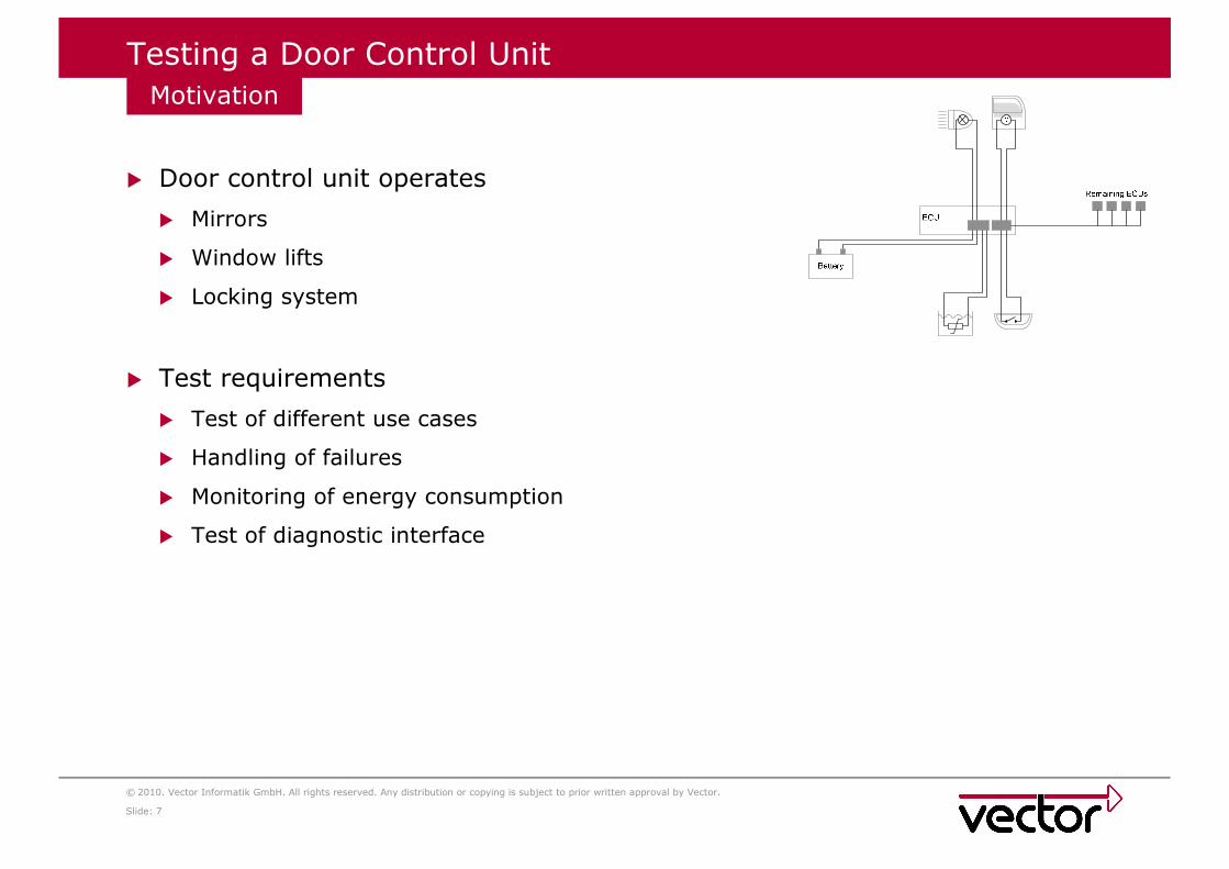
Testing a Door Control Unit
� Door control unit operates
� Mirrors
� Window lifts
� Locking system
� Test requirements
� Test of different use cases
� Handling of failures
� Monitoring of energy consumption
� Test of diagnostic interface
Motivation
8
© 2010. Vector Informatik GmbH. All rights reserved. Any distribution or copying is subject to prior written approval by Vector.
Slide:
M
Battery
ECU
Remaining ECUs
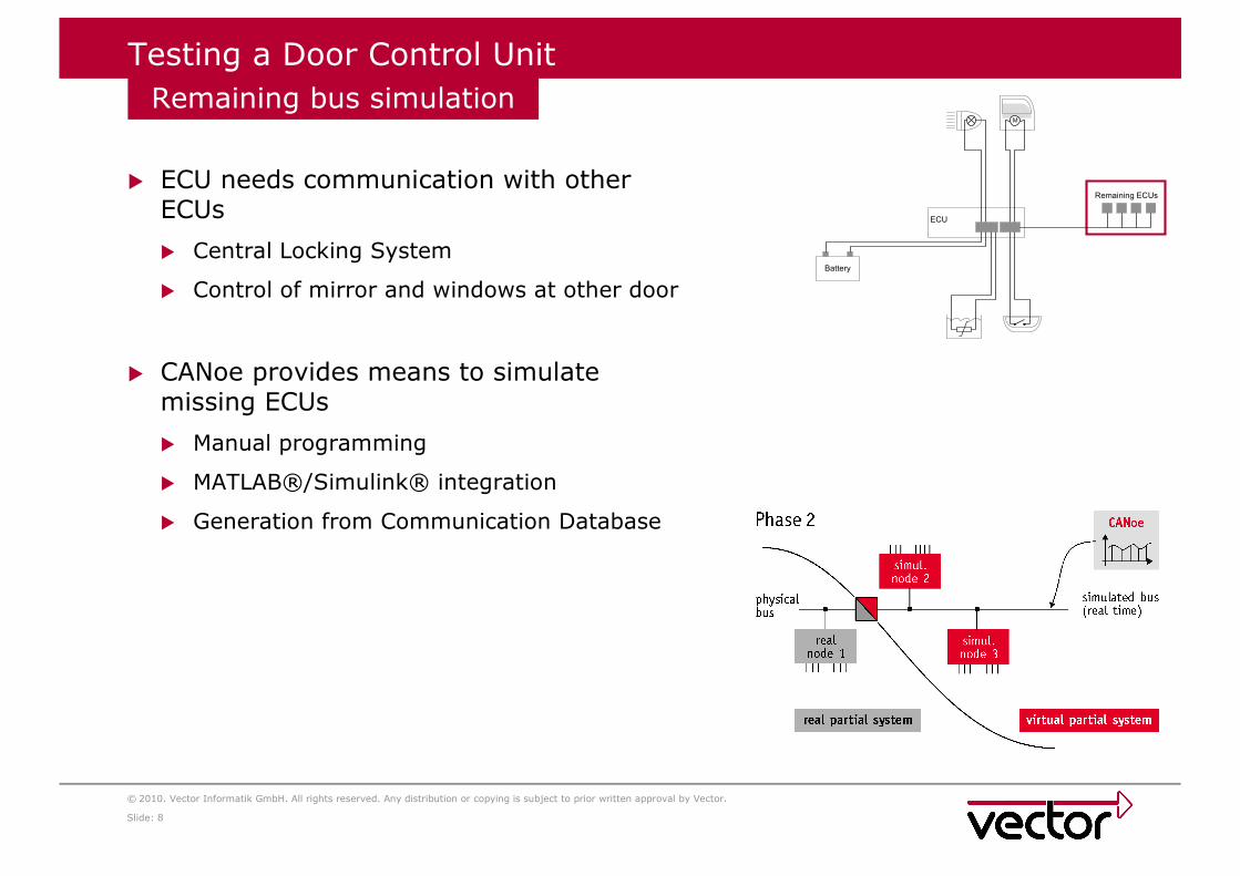
Testing a Door Control Unit
� ECU needs communication with other ECUs
� Central Locking System
� Control of mirror and windows at other door
� CANoe provides means to simulate missing ECUs
� Manual programming
� MATLAB®/Simulink® integration
� Generation from Communication Database
Remaining bus simulation
9
© 2010. Vector Informatik GmbH. All rights reserved. Any distribution or copying is subject to prior written approval by Vector.
Slide:
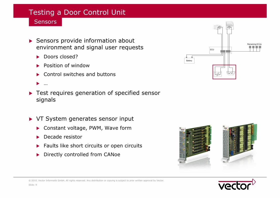
Testing a Door Control Unit
� Sensors provide information about environment and signal user requests
� Doors closed?
� Position of window
� Control switches and buttons
� …
� Test requires generation of specified sensor signals
� VT System generates sensor input
� Constant voltage, PWM, Wave form
� Decade resistor
� Faults like short circuits or open circuits
� Directly controlled from CANoe
SensorsM
Battery
ECU
Remaining ECUs

10
© 2010. Vector Informatik GmbH. All rights reserved. Any distribution or copying is subject to prior written approval by Vector.
Slide:
Testing a Door Control Unit
� Actuators are operated by ECU according to sensor input and internal state
� Window lift motor
� Mirror servo
� Lock
� ECU detects missing actuators
� Test checks output for specified combinations of input signals
ActuatorsM
Battery
ECU
Remaining ECUs
11
© 2010. Vector Informatik GmbH. All rights reserved. Any distribution or copying is subject to prior written approval by Vector.
Slide:
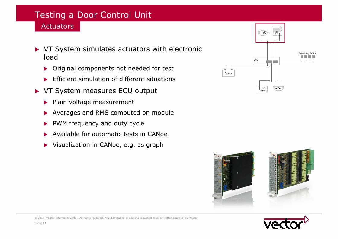
Testing a Door Control Unit
� VT System simulates actuators with electronic load
� Original components not needed for test
� Efficient simulation of different situations
� VT System measures ECU output
� Plain voltage measurement
� Averages and RMS computed on module
� PWM frequency and duty cycle
� Available for automatic tests in CANoe
� Visualization in CANoe, e.g. as graph
ActuatorsM
Battery
ECU
Remaining ECUs
12
© 2010. Vector Informatik GmbH. All rights reserved. Any distribution or copying is subject to prior written approval by Vector.
Slide:
M
Battery
ECU
Remaining ECUs
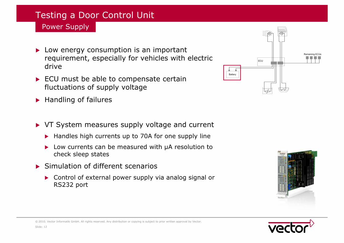
Testing a Door Control Unit
� Low energy consumption is an important requirement, especially for vehicles with electric drive
� ECU must be able to compensate certain fluctuations of supply voltage
� Handling of failures
� VT System measures supply voltage and current
� Handles high currents up to 70A for one supply line
� Low currents can be measured with µA resolution to check sleep states
� Simulation of different scenarios
� Control of external power supply via analog signal or RS232 port
Power Supply

13
© 2010. Vector Informatik GmbH. All rights reserved. Any distribution or copying is subject to prior written approval by Vector.
Slide:
M
Battery
ECU
Remaining ECUs
Testing a Door Control Unit
� Test of diagnostic functions
� CANoe provides diagnostic framework
� Support for CANdela and ODX databases
� VT System can be used in automated diagnostic tests with DiVa e.g. for fault injection
� White Box testing with direct access to internal values of the ECU
� CANoe provides CCP and XCP interface
� Test control with CANoe Test Feature Set
� Test sequences can be created using XML, CAPL or .NET
� Automatic generation of test reports
ECU Access and Test Control
14
© 2010. Vector Informatik GmbH. All rights reserved. Any distribution or copying is subject to prior written approval by Vector.
Slide:
Agenda
Summary and Outlook>
Testing a Door Control Unit
ECU Testing
15
© 2010. Vector Informatik GmbH. All rights reserved. Any distribution or copying is subject to prior written approval by Vector.
Slide:
Summary and Outlook
� Integrated all-in-one hardware interface for ECU I/O testing
� All basic test components included (relays, decade resistor, …)
� Fills gap between standard I/O card and ECU under test
� Fulfills automotive test requirements concerning voltage, currents, latency, through-put, …
� Simplifies wiring of even complex test stands
� Fully integrated in CANoe: direct and simple control of I/O for test, simulation, and analysis
� Scalable test solution: from compact off-the-shelf I/O box at developer’s desk to component HIL racks in the lab
Benefits

16
© 2010. Vector Informatik GmbH. All rights reserved. Any distribution or copying is subject to prior written approval by Vector.
Slide:
Summary and Outlook
� Dedicated PC Module for real-time part of CANoe
� Atom or Core 2 Duo CPU on highly flexible COM Express module
� Improvement of real-time capabilities
� Network Interface Module VT6104
� 4 channel CAN, LIN
� Based on well-established CANcard XLe technology
� Contains relays for short circuit, open wire, termination
� Extension Module VT7900
� Base board for the realization of application-specific VT System modules
� Digital and analog I/Os allow simple application boards
Upcoming Extensions

17
© 2010. Vector Informatik GmbH. All rights reserved. Any distribution or copying is subject to prior written approval by Vector.
Slide:
Thank you for your attention.
For detailed information about Vector
and our products please have a look at:
www.vector.com
Author:
Vector Informatik GmbH
Ingersheimer Str. 24
70499 Stuttgart