Vt-737sp Manual 2 - Avalon · PDF fileVT-737SP Avalon Industries, Inc., 3715 Cahuenga Blvd,...
58
VT-737SP Pure Class A Mono Vacuum Tube / Discrete Preamplifier, Opto-compressor & Equalizer Operation Manual © 2016 Avalon Industries Incorporated. Release 2.0 DESIGN AVALON P URE C LASS A M USIC R ECORDING S YSTEMS
Transcript of Vt-737sp Manual 2 - Avalon · PDF fileVT-737SP Avalon Industries, Inc., 3715 Cahuenga Blvd,...

V T- 7 3 7 S P
P u r e C l a s s A M o n o Va c u u m Tu b e / D i s c r e t eP r e a m p l i f i e r , O p t o - c o m p r e s s o r & E q u a l i z e r
Operation Manual© 2016 Avalon Industries Incorporated. Release 2.0
DE S I G NAVA LONP U R E C L A S S A M U S I C R E C O R D I N G S Y S T E M S

V T- 7 3 7 S P
Avalon Industries, Inc., 3715 Cahuenga Blvd, Studio City, CA 91604Tel: 949-492-2000 www.avalondesign.com
Operation Manual


Table of Contents1.0 Introduction . . . . . . . . . . . . . . . . . . . . . .5 1.1 Overview . . . . . . . . . . . . . . . . . . . . .6 1.2 Features . . . . . . . . . . . . . . . . . . . . . .7 1.3 Unpacking and Inspection . . . . . . . . .8
2.0 Quick Start-up . . . . . . . . . . . . . . . . . . . . .9 2.1 Setup Guide . . . . . . . . . . . . . . . . .10 2.2 Tips . . . . . . . . . . . . . . . . . . . . . .11
3.0 Safety and Grounding . . . . . . . . . . . . .12 3.1 Safety Instructions . . . . . . . . . . . .12 3.2 Grounding Instructions . . . . . . . . .12 3.3 AC Voltage Selection . . . . . . . . . .13 3.4 Rack Mounting and Cooling . . . . .14 3.5 Turn-on Procedure . . . . . . . . . . . .14
4.0 Operation and Controls . . . . . . . . . . . .15 4.1 Rear Panel Description . . . . . . . .18 4.2 Connections . . . . . . . . . . . . . . . .18 4.3 Unbalanced Operation . . . . . . . .19 4.4 Using the Vt-737sp . . . . . . . . . .19 4.4.1 Using the Mic Preamplifier. . . . .19 4.4.2 Using the Opto-compressor . . . .20 4.4.3 Linking Two Vt-737sp’s . . . . . . .21 4.4.4 Using the Equalizer . . . . . . . . . .21 4.4.5 Using the Side Chain . . . . . . . . .22 4.4.6 De-essing Vocals . . . . . . . . . . . .22
5.0 Applications . . . . . . . . . . . . . . . . . . . .23 5.1 Typical Setups . . . . . . . . . . . . . . .23 5.1.1 Recording . . . . . . . . . . . . . . . . .23 5.1.2 Mixdown - Tape Based . . . . . . .24 5.1.3 Mixdown - DAW . . . . . . . . . . . . .24 5.1.4 Mixdown / Mastering - DAW . . . .24 5.1.5 Mastering - Tape Based . . . . . . .24
5.2 Application Settings . . . . . . . . . . . . .24 5.2.1 Vocals . . . . . . . . . . . . . . . . . . . . . .25 5.2.2 Vocals with De-ess . . . . . . . . . . . .26 5.2.3 Bass Guitar . . . . . . . . . . . . . . . . . .27 5.2.4 Acoustic Guitar . . . . . . . . . . . . . . .28 5.2.5 Electric Guitar . . . . . . . . . . . . . . . .29 5.2.6 Acoustic Piano . . . . . . . . . . . . . . .30 5.2.7 Snare Drum . . . . . . . . . . . . . . . . . .31 5.2.8 Kick Drum. . . . . . . . . . . . . . . . . . . .32 5.2.9 Drum Overheads/Cymbals . . . . . .33
6.0 Basics . . . . . . . . . . . . . . . . . . . . . . . . . . .34 6.1 Impendance . . . . . . . . . . . . . . . . . . .34 6.2 Balanced vs. Unbalanced . . . . . . . .34 6.3 Cables and Connectors . . . . . . . . . .35 6.4 Microphones . . . . . . . . . . . . . . . . . . .35 6.5 Preamplifiers. . . . . . . . . . . . . . . . . . .36 6.6 Compression . . . . . . . . . . . . . . . . . .37 6.7 Equalization . . . . . . . . . . . . . . . . . . .38
7.0 FAQs (Frequently Asked Questions) . . . . . .39
8.0 Trouble Shooting . . . . . . . . . . . . . . . . . . .42
9.0 Service and Contact Infomation . . . . . . .42
10.0 Technical Information . . . . . . . . . . . . . .45 10.1 Recall Sheets . . . . . . . . . . . . . . . .46 10.2 Block Diagram . . . . . . . . . . . . . . . .47 10.3 Vt-737 (purple) vs. Vt-737sp . . . . .48
11.0 Warranty . . . . . . . . . . . . . . . . . . . . . . . . .48 11.1 Returns . . . . . . . . . . . . . . . . . . . . .49
12.0 Safety Standards . . . . . . . . . . . . . . . . . .49
Appendix A - Glossary . . . . . . . . . . . . . . . . . .50

Page 5Avalon Vt-737sp Operation Manual
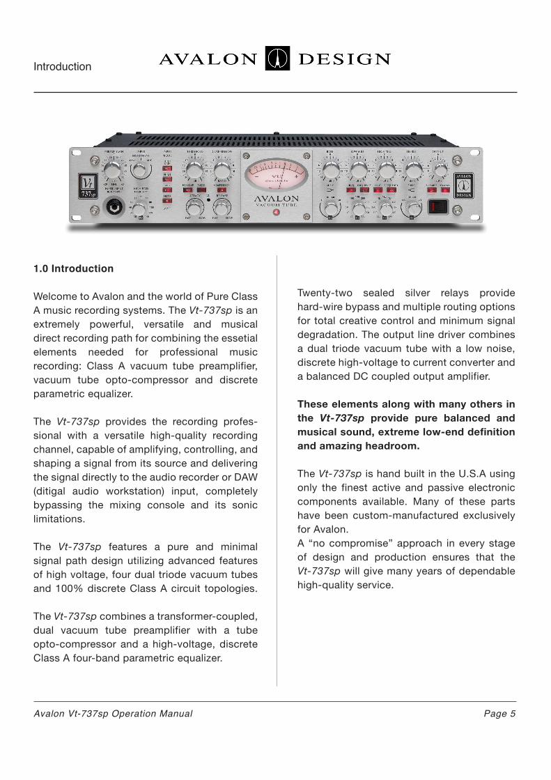
1.0 Introduction
Welcome to Avalon and the world of Pure Class A music recording systems. The Vt-737sp is an extremely powerful, versatile and musical direct recording path for combining the essetial elements needed for professional music recording: Class A vacuum tube preamplifier, vacuum tube opto-compressor and discrete parametric equalizer.
The Vt-737sp provides the recording profes-sional with a versatile high-quality recording channel, capable of amplifying, controlling, and shaping a signal from its source and delivering the signal directly to the audio recorder or DAW (ditigal audio workstation) input, completely bypassing the mixing console and its sonic limitations.
The Vt-737sp features a pure and minimal signal path design utilizing advanced features of high voltage, four dual triode vacuum tubes and 100% discrete Class A circuit topologies.
The Vt-737sp combines a transformer-coupled, dual vacuum tube preamplifier with a tube opto-compressor and a high-voltage, discrete Class A four-band parametric equalizer.
Twenty-two sealed silver relays provide hard-wire bypass and multiple routing options for total creative control and minimum signal degradation. The output line driver combines a dual triode vacuum tube with a low noise, discrete high-voltage to current converter and a balanced DC coupled output amplifier.
These elements along with many others in the Vt-737sp provide pure balanced and musical sound, extreme low-end definition and amazing headroom.
The Vt-737sp is hand built in the U.S.A using only the finest active and passive electronic components available. Many of these parts have been custom-manufactured exclusively for Avalon. A “no compromise” approach in every stage of design and production ensures that the Vt-737sp will give many years of dependable high-quality service.
Introduction

Page 6 Avalon Vt-737sp Operation Manual
Introduction
1.1 Overview
The Vt-737sp combines three essential fuctions needed for professional recording: preamplifier, compressor and equalizer. The Vt-737sp is designed to completely bypass the mixing board during input to deliver the purest and cleanest signal possible to your recording device. It works wonderfully for recording directly into a digital device giving the signal a richer and fuller sound. Each function of the Vt-737sp can be used separately either as a preamp, a compressor, or an equalizer, or all functions can be combined in many different ways for ultimate creativity and unique new sounds.
The Vt-737sp preamplifier is a high voltage vacuum tube design that can be used for all types of microphones, direct instruments such as guitars and basses, and for line level devices such as keyboards, mixing boards, recorders or DAWs. Three different devices can be plugged into the Vt-737sp simultaneously and can be easily selected with the input mode switch on the front panel. The microphone input has continu-ously variable gain from 0dB to +58dB includ-ing selectable 48 volt phantom power. A high impendance (one megohm) input directly into the vacuum tube circuit through an unbalanced 1/4” jack located on the front panel is used for directly recording electric guitars or basses.
The compressor of the Vt-737sp utilizes twin triode class-A vacuum tube circuitry with an optical attenuator used as the gain reduction element. The continuously variable threshold level, compression ratio, attack, and release controls can be easily adjusted to achieve a variety of useful dynamic effects, from soft compression to hard-knee limiting.
The choice of gain reduction level or input level can be monitored on the VU meter. The com-pressor can be positioned either before or after (pre or post) the equalizer giving even further sonic flexibility. (Normal is pre EQ)
An added feature of the Vt-737sp is its side-chain fuction for frequency selective com-pression capabilities. When the side-chain switch is engaged, the two mid-band filters of the equalizer section are inserted into the compressor’s control circuit path, allowing for frequency-sensitive dynamics control. The wide frequency-range filters allow for a variety of compression actions including de-essing (sibilance control), or limited fr- equency- range tightening and spectral control.
A 1/4” unbalanced Stereo Link jack is also provided on the rear of the unit to link two Vt-737sp’s together for stereo operation.
The Vt-737sp equalizer is a 100% discrete high voltage class A four-band parametric equalizer, using both variable-active and switched-pas-sive filter topologies. The TREBLE control is a smooth, passive shelving type filter selectively switched at 10kHz, 15kHz, 20kHz, and 32kHz with +/-20dB of amplitude control. The BASS control is also a passive shelf filter with select-able bands centered at 15Hz, 30Hz, 60Hz, and 150Hz. It also has +/-24dB of amplitude con-trol. The Low Mid bandis an active peak/dip filter, continuously variable from 30Hz to 450Hz. The x10 switch shifts the frequency range from 300Hz to 4.5kHz, overlapping the bands to give a possible range of 30Hz to 4.5kHz.
It has +/-16dB amplitude control and a high/low Q (bandwidth) swtich which musically sharpens the filter’s response from a Q of 0.2 (wide) to 0.85 (medium). The High Mid band filter section is of the same type and covers a frequency band of 200Hz to 2.8kHz. With the X10 switch engaged, the filter covers the 2kHz to 28kHz range. A high/low Q switch changes the bandwidth in the same way as the Low Mid band.
The output stage of the Vt-737sp is another twin-triode vacuum tube stage driving a balanced low-noise Class A DC-coupled output amplifier. This stage includes an output level control to give the final level adjustment before leaving the unit via an XLR connector.
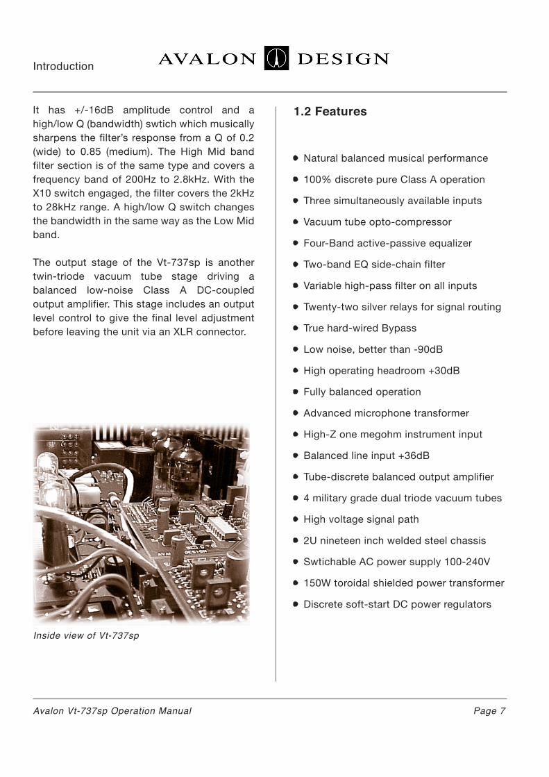
Inside view of Vt-737sp
1.2 Features
• Natural balanced musical performance
• 100% discrete pure Class A operation
• Three simultaneously available inputs
• Vacuum tube opto-compressor
• Four-Band active-passive equalizer
• Two-band EQ side-chain filter
• Variable high-pass filter on all inputs
• Twenty-two silver relays for signal routing
• True hard-wired Bypass
• Low noise, better than -90dB
• High operating headroom +30dB
• Fully balanced operation
• Advanced microphone transformer
• High-Z one megohm instrument input
• Balanced line input +36dB
• Tube-discrete balanced output amplifier
• 4 military grade dual triode vacuum tubes
• High voltage signal path
• 2U nineteen inch welded steel chassis
• Swtichable AC power supply 100-240V
• 150W toroidal shielded power transformer
• Discrete soft-start DC power regulators
Avalon Vt-737sp Operation Manual Page 7
Introduction

1.3 Unpacking and Inspection
Your Vt-737sp was packed carefully at the factory. Check to make sure that the shipping carton contains the following items:
1. Vt-737sp2. Power cable3. Warranty card4. Operation Manual
Keep the packaging materials in case you need to ship your unit for warranty service.
Note: Your must fill out and send in your war-ranty card in order to receive warranty and technical support. If you have not already filled out your warranty card please take the time to do so now.
Vt-737sp contents and packing
Page 8 Avalon Vt-737sp Operation Manual
Introduction

Page 9
figure 2.0 Quick Start up
Avalon Vt-737sp Operation Manual
2.0 Quick Start-up
The following chapter is designed to help you get started using your Vt-737sp right away without having to read the entire manual. Make sure however to take time to read the manual at a later date as there are many safety aspects and features of the Vt-737sp that will not be discussed here.
If you are familiar with this type of equipment you can also familiarize yourself with your Vt-737sp and the functions with the Quick Start-up Guide on page 10.
Note: The Vt-737sp is an extremely high performance piece of musical equipment. Every setting has great potential for creating new and innovative musical sounds. Do not be afraid of turning the knobs to their full extreme positions!
Hook it up, turn it on and play:
1. Check on the rear of your unit that the power supply is set for your local AC voltage. (120V in U.S.) Refer to chapter 3.3 page 13 for details.
2. Plug in the AC power cable and connect your microphone to the XLR input of the Vt-737sp or an Instrument to the 1/4” jack on the front panel. If your microphone needs
phantom power, push in the button labeled +48V. Switch the input selector knob to indi-cate which input you are using (mic for the microphone input, instrument for instrument input, or line for line input). Connect the XLR output to your recording device, powered speaker or monitoring system.
3. Turn on the power and wait for one minute while the soft-start procedure commences. You may hear a relay click at about 45 sec-onds. During the soft-start procedure, the Vt-737sp is in hard-wire bypass mode and will pass signal, but the controls will not work. For optimum performance, allow 30 minutes for the Vt-737sp to fully warm up.
4. With all switches in the dis-engaged (non-il-luminated) position, put signal through the Vt-737sp with the input device you are using. Adjust the output control on the right hand side of the unit to check basic operation.
5. Now you are ready to start pressing switch-es and turning knobs! Let your ears guide your sounds.
The Quick Set-Up Guide on the following page gives a brief description of the switches and controls on the Vt-737sp.
Mixing Console or
Monitoring System
Vt-737sp
Microphone
Instrument
Line Signal
-OR-
-OR-
Output
Input
Hi-ZInstrument Input
Mic Input
Line Input
Quick Start-up
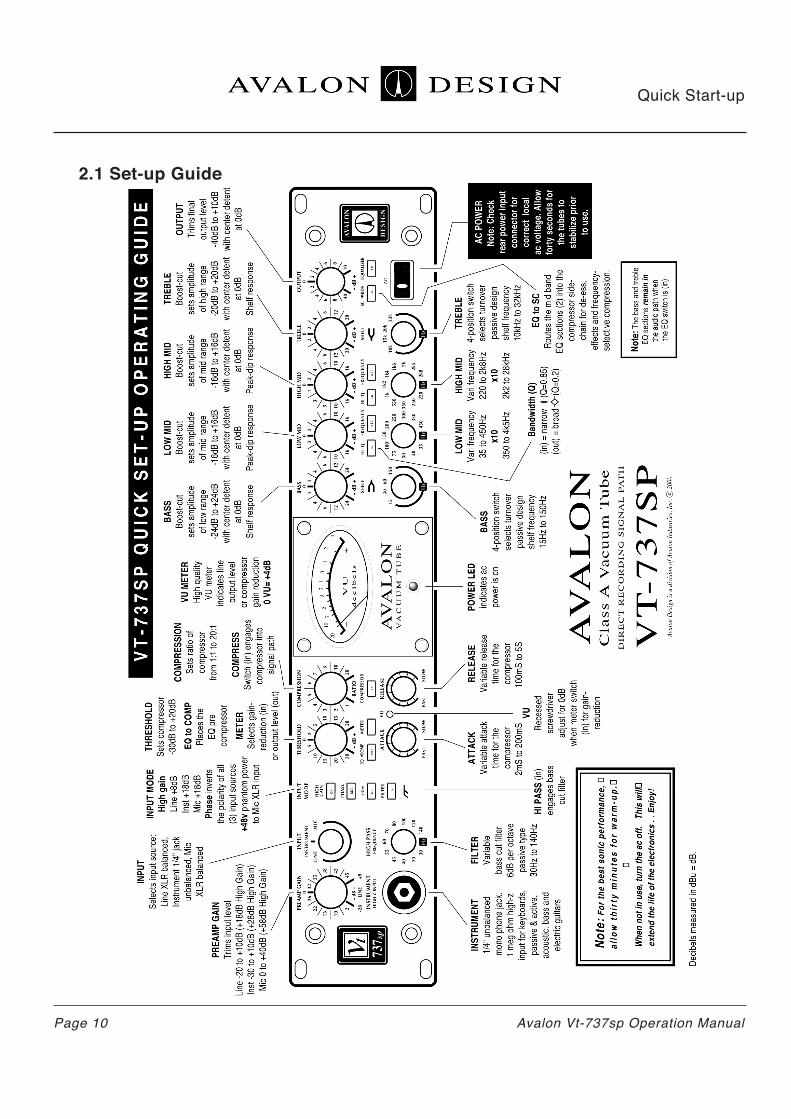
2.1 Set-up Guide
Page 10 Avalon Vt-737sp Operation Manual
Quick Start-up
Page 11Avalon Vt-737sp Operation Manual
2.2 Tips
UNITY LEVEL - The VT-737sp is calibrated so that unity level is 0dB VU=+4dBu output. PREAMP GAIN - Use the preamp gain control as a gain control, not a level control. Turning up the PREAMP GAIN will drive the tubes harder for different tonality.
OUTPUT - Use the output control as the overall level control.
EQ->COMP - Inserts the four band parametric EQ before the compressor in the signal path.
SC-MID - Engages the built in side-chain. The frequencies boosted in the Mids of the EQ will be routed to the compressor control circuit (not in the audio path) so that those frequencies are compressed more than the overall program; great for de-essing.
2.3 Tutorial - Using it all
The following is a tutorial that will quickly get you familiar with all of the functions of the Vt-737sp. Follow the steps below and in a few minutes you will have used all of the functions of the Vt-737sp.
Start by plugging a line level signal (CD player, stereo keyboard, submix output, etc) into the LINE INPUT in the rear of your Vt-737sp. If pos-sible, run directly out of the Vt-737sp to moni-tors bypassing the console or mixing board. Choose a musical selection, loop, patch, sample or instrument with wide dynamic and frequency range so you can experiment with the compressor and equalizer.
Set all push button switches to their disen-gaged or non-illuminated position.
1. INPUT - Set to 0 center position. Adjust OUTPUT control to set monitoring level.
2. HIGH GAIN - Press in and out to get a feel for the sound of the high gain switch. Leave it non-illuminated.
3. EQUALIZER - Press in equalizer switch and familiarize yourself with the four band para-metric band equalizer. Adjust the TREBLE Hz frequency selector switch to 10K. Turn the TREBLE knob up and down. You are now boosting all frequencies at and above 10k. Experiment with 15k, 20k, and 32k positions. Leave the TREBLE level control at center 0 position. The BASS controls only the shelf is in the opposite direction. So if you boost the BASS at 60Hz you are boosting everything at and below 60Hz.
Turn up the HIGH MID to +16. (Turn down the OUTPUT if needed). Turn the corresponding Hz knob directly below HIGH MID to 1k. This means you are boosting the frequencies at and around 1k by +16dB. Press in HI-Q. This means your bandwidth around the 1k fren-quencies is narrower or more focussed on 1k. Now press in the X10 (read “times ten”) switch. Now you are boosting the frequencies at 10k (1k x 10 + 10k).
The LOW MID controls operate in the same manner as the HI MID but cover a lower range of frequencies.
Push the EQUALIZER swtich out (off) and leave the EQ settings as they are (boosting 10kHz by +16dB).
Quick Start-up

3.0 Safety and Grounding
The following chapter describes how to safely install your Vt-737sp for optimal sonic perfor-mance.
3.1 Safety Instructions
This unit contains voltages that can cause seri-ous injury or death. Do not operate with the covers removed.
Improper connection of the equipment-ground-ing cable can result in a risk of electric shock.
Check with a qualified electrician or serviceman if you are in doubt about your electrical power or ground connection. The Vt-737sp is for use with an AC supply as selected by the AC volt-age selector (located within the AC inlet on the rear of the chassis). Voltages are 100-120-220-240VAC +/-0.5%, 50-60Hz at 75 watts.
3.2 Grounding Instructions
Always connect the Vt-737sp to a grounded AC power circuit.
If the unit should malfunction or become “live”, the chassis ground will provide the path of least resistance for electric current to reduce the risk of fatal shock.
4. COMPRESSOR - Press in the COMPRES-SOR switch and turn the main compression controls to the following:
COMPRESSION - full clockwise (20:1) THRESHOLD - full counter clockwise (-30dB) ATTACK - full counter clockwise (Fast) RELEASE - full clockwise (Slow)
This is full compression with fast attack and slow release. You can probably hear the com-pressor “pumping” or “breathing”. Play with the compression controls to get a feel for the compressor.
Leave the controls at full compression with fast attack and fast release.
5. EQ->COMP - Press in EQUALIZER switch (boosting 10kHz by +16dB). Press EQ->COMP switch to insert the EQ before the compressor in the signal path. This compresses the filtered or “equalized” signal.
6. Press in SC->MIDS. You are now routing the 10K frequencies that were being boosted into the compressor. This will compress the previ-sously boosted 10kHz frequencies more than the other frequencies. Experiment now with the HIGH MID level control to adjust the compres-sion at 10kHz.
Now you have full compression, with fast attack and slow release, and frequencies at 10K going into the side chain being com-pressed more than the overall signal.
You have now used all of the functions in the Vt-737sp. The combinations, colors, and tones are endless. For more details on each specific control and fuction please refer to Chapter 4, Operations and Controls (page 15).
Safety andGrounding
Page 12 Avalon Vt-737sp Operation Manual

This product is equipped with an AC power inlet and must be connected to a three-wire grounded plug.
The AC power cable must be plugged into an appropriate outlet that is correctly installed and grounded in accordance with all local elec-trical safety codes and ordinances.
If hum or ground-buzz is induced into the system, remove the rear-mounted GROUND-LINK. This is ground-link isolates the AC chassis ground from the audio ground. When the LINK is removed, the AC ground remains connected to the chassis via the AC inlet connector and provides a direct path for any electrical fault or dangerous condition.
Warning! No ground adaptor should ever be used with this unit.
3.3 AC Voltage Selection
Before connecting the Vt-737sp to the AC supply, check the OPERATING VOLTAGE located on the rear of the chassis in the AC inlet connector.
Voltages available are 100-120-220-240VAC +/-0.5% 50-60Hz at 75 watts (USA used 120V).
To change the AC voltage for your location:
1. Make sure there is no AC power cable con-nected to the AC inlet.
2. Insert a small flat-head screwdriver tip into the voltage selector cavity. Carefully lift-open the hinged cover from left to right.
3. Rotate the selector wheel to show the correct voltage for your location, then push the wheel firmly into the mounting tabs.
4. Press the voltage selector cover snap-shut, check correct AC voltage in window.
5. Connect the grounded AC power cable.
Safety andGrounding
Page 13Avalon Vt-737sp Operation Manual

3.4 Rack Mounting and Cooling
The Vt-737sp is designed to be mounted in a standard 19” equipment rack. As vacuum tubes and Class A circuitry generate heat, it is highly recommended that an additional rack space above and below the unit be kept empty to allow for adequate cooling. Avalon Design has developed 1U ventilation panels (VP-1) specfi-cally to keep your rack-mounted gear cool.
Be sure that the top and bottom of the unit is not obstruced and air is allowed to flow easily through the chassis. If the unit is not rack-mounted, be sure to place supports under the unit to allow air to pass underneath. Never leave any obstruction on top of the unit (such as papers or books) blocking ventilation slots. Also, be sure that the heat sink mounted on the rear panel of the chassis has adequate clear-ance from the equipment enclosure and any adjacent equipment. In electronic equipment, excessive heat is the cause of most component failures. A little extra precaution to ensure proper ventilation can help avoid equipment
Always use all four front panel-mounting holes when mounting the Vt-737sp in a rack enclosure. If not shipped in its original pack-ing, the Vt-737sp should be transported in a floating-type shock-mounted flight case.
Although the Vt-737sp is well shielded against moderate electrical and magnetic feilds, care should be taken to avoid areas that are in proximity to large motor or power transform-ers. Locations near sources of high RFI (radio frequency interference) such as computers or digital effects devices should also be avoided. Because of the microphonic nature of vacuum tubes, areas of extreme vibration or sound levels should also be avoided.
3.5 Turn-on Procedure
The Vt-737sp is designed with a “soft-start” feature that slowly brings the unit to life when the unit is powered on. This feature ensures that there is no strain on the electronic com-ponents when it is activated. It takes approxi-mately 45 seconds for the unit to go through the “soft-start” turn-on procedure.
When the Vt-737sp is switched off or during the “soft-start” turn-on procedure, it is in hard wire bypass mode and the unit will pass signal utlizing a hard wire relay but none of the con-trols will operate (line in to line out).
Allow the unit to warm up for at least thirty minutes prior to use. This allows the compo-nents time to come up to temperature and stabilize before recording begins.
It is recommended that the unit be turned off during periods of “non-use” greater than 4 hours.
Safety andGrounding
Page 14
Avalon VP-1 vent panels
Avalon Vt-737sp Operation Manual

Operation andControls
Page 15Avalon Vt-737sp Operation Manual
4.0 Operation and Controls
The following chapter describes the details of your Vt-737sp and how to operate each func-tion.
Continuously variable rotary control adjusts input level of signal. This control will drve the tubes harder to get more tube tone into the preamp. The input has +36dB of headroom before overload. You can use this control at min-imum and maximum levels for different sounds and colors. This control is a carefully configured dual level control and does not change the feed-back of the tubes.
3-position rotary switch that selects between LINE, INSTRUMENT, or MIC input sources. This switch corresponds to the following physical input connections on the Vt-737sp:
LINE - XLR input on back labeled LINEINSTRUMENT - 1/4” input jack on the front panel labeled INTSRUMENT HIGH-Z INPUT MIC - XLR input on back labeled MICROPHONE
All three input sources may be connected simul-taneously but only the source that is selected by the INPUT switch is active.
Boosts overall gain of the input/preamplifier section by +8dB in Line mode and +18dB in Mic or Instrument modes. The HIGH GAIN switch fuctions with any selected INPUT position. This extra signal boost can be effectively used in conjunction with the OUTPUT control to over-drive the vacuum tube stages. Various effects, from soft tube overdrive to all out distortion can be achieved.
Reverses the output polarity. This feature allows all three inputs the option of phase reversal. Experiment with the phase switch to defeat phase cancellation and create musical effects. The Vt-737sp always operates in “true phase” from the input source to the output jack, wheth-er bypassed or in-line (ie., a positive voltage on input pin 2 yields a positive voltage on output pin 2).
This control sets compressor threshold level. Continuously variable from -30dB to +20dB.
When engaged the VU meter monitors the gain reduction of the compressor. When disen-gaged, the VU meter monitors output level.
3 HIGH GAIN
4 PHASE
5 THRESHOLD
6 METER
2 INPUT
1 PREAMP GAIN

Operation andControls
Page 16 Avalon Vt-737sp Operation Manual
Sets the compression ratio. Continuously vari-able from 1:1 to 20:1.
When switch is engaged, the compressor is inserted into the signal path. When disen-gaged, the compressor section is hard bypassed by a sealed silver-contact relay.
Can be selected with the METER switch to indicate either output level (non-illuminated) or compressor gain reduction (illminated). The VU meter’s needle is also speed sensitive for mea-suring gain reduction. This helps in setting the ATTACK and RELEASE of the compressor
Sets amplitude (cut/boost)of bass band. Vari-able +/-16dB, with center detent.
Sets amplitude (cut/boost) of low mid band. Variable +/-20dB with center detent.
Sets amplitude of high mid band. Variable +/-16dB, center detent.
Sets amplitude (cut/boost) of shelving treble frequency band. Variable +/-20dB with center detent.
Inserts both of the mid band filter sections of the equalizer into the compressors’ control path, allowing for frequency-selective com-pression applications (e.g. de-essing vocals).
Adjusts the final output level. Variable -45dB to +10dB, with center detent at 0 dBu.
Inserts equalizer into signal path. When disen-gaged, equalizer section is hard wire bypassed by a sealed silver-contact relay.
1/4” unbalanced phone jack. High impendance input selected when INPUT is in INSTRUMENT position. Also known as D.I. (direct input. Instru-ments such as electric guitars and basses can be directly plugged into this jack via a standard shielded guitar cable.
Continuously variable rotary control that varies the cut-off frequency of a passive high-pass filter on the output of the preamp section. This simple, smooth filter rolls off the low-end frequencies and works well for reducing room rumble, muddiness or microphone handling noise.
Engages the preamp high pass frequency filter. When the FILTER switch is not engaged, the filter is hard wire bypassed.
48V phantom power is applied to microphone input XLR. Both pins 2 and 3 carry 48V. Phan-tom power is necessary for most condenser microphones that do not have their own exter-nal power supply.
A microphone that requires phantom power will not work unless the +48V switch is engaged.
8 COMPRESSOR
9 VU METER
10 BASS
11 LOW MID
12 HIGH MID
13 TREBLE
14 SC->MIDS
7 COMPRESSION (RATIO) 15 OUTPUT
16 EQUALIZER
17 INSTRUMENT (HIGH-Z INPUT)
18 HIGH PASS FREQUENCY
19 FILTER
20 +48v

Switches the signal so that the equalizer sec-tion is before the compressor. This gives flexi-bility to achieve different sounds. Putting the EQ before the compressor will give the signal a more squashed or tighter sound than if the EQ follows the compressor.
Varies attack time of compressor from 2ms to 200ms.
Recessed screwdriver adjustment for setting of 0dB on the VU meter when set to read the compressor’s gain reduction.
To calibrate meter: Wait about 30 mintues affter switching the unit on allowing compo-nents to sufficiently warm up to opertating temperature. While there is no signal going into the Vt-737sp, press in the METER switch and make sure the compressor is bypassed (non-illuminated). Adjust so that the needle on the VU meter lines up with zero.
Engages the preamp high pass frequency filter. When the FILTER switch is not engaged, the filter is hard wire bypassed.
4-position switch selects shelving frequency of the passive BASS band. Setting selections are 15Hz, 20Hz, 60hz, and 150Hz.
When engaged, narrows the bandwidth of the low-mid band frequency selected from an approximate Q of 0.2 to 0.85.
Switches the signal so that the equalizer sec-tion is before the compressor. This gives flexi-bility to achieve different sounds. Putting the EQ before the compressor will give the signal a more squashed or tighter sound than if the EQ follows the compressor.
Push-button switch when engaged (illuminat-ed “X10”), multiplies the normally covered Hz frequency band )30Hz to 450Hz) by ten (300Hz to 4k5Hz).
Push button switch when engaged (illuminated “IN”), narrows the bandwidth of the Hz high-mid band selected, from a Q of approxi-mately 0.2 to 0.85.
Sets center frequency of high mid filter sec-tion. Continuously variable from 200Hz to 2k8Hz (or 2kHz to 28KHz in X10 mode).
When engaged (illuminated X10), multiplies the normally covered frequency band (200Hz to 2k8Hz) by ten (2kHz to 28kHz).
4-position switch selects shelving frequency of the passive TREBLE band. Setting selec-tions are 10kHz, 15kHz, 20kHz, and 32kHz.
Turns the power on and off. Allow approxi-mately 60 seconds from the time you turn on the power switch for the Vt-737sp to complete the entire soft start turn on procedure. For more details on the soft start procedure please refer to Chapter 3.5 Turn-on Procedure (page
21 EQ->COMP 27 Hz (LOW MID)
28 FREQUENCY X10 (LOW MID)
29 FREQUENCY X10 (LOW MID)
30 Hz (HIGH MID)
31 FREQUENCY X10 (HIGH MID)
32 HZ (TREBLE)
33 AC Power Switch
22 ATTACK
23 VU METER (0dB calibration screw)
24 RELEASE
25 Hz (BASS)
26 HI-Q (LOW MID)
Operation andControls
Page 17Avalon Vt-737sp Operation Manual

Operation andControls
Page 18 Avalon Vt-737sp Operation Manual
4.1 Rear Panel Description
2-terminal barrier strip. Isolates chassis ground from audio ground. To lift ground, simply unscrew both phillips-head screws and remove the metal strip held down by the screws. Do not remove this link unless you experience hum or AC noise.
Combination IEC socket, voltage selector and fuse location. AC Voltage is factory set as ordered. To change the factory voltage setting, refer to the AC Voltage Selection sec-tion of this manual in Chapter 3 (page 13), or contact your authorized Avalon dealer.
To change the fuse, open the cover of the AC voltage unit and pull the fuse lever.
Unbalanced 1/4” phone jack. Used for linking compressor sections of two Vt-737sp’s for stereo operation.
Male XLR-3 connector, line output of unit. Balanced DC-coupled, capable of +30dB into 600 ohms.
Female XLR-3 connector. Active input when INPUT is set to LINE. Balanced input for line level signals to +36dB maximum.
Female XLR-3 connector. Active input when INPUT is set to MICROPHONE. For micro-phone-level signals to +30dB maximum. Also provides +48V phantom power to micro-phone when +48V switch is engaged.
4.2 Connections
The LINE INPUTS are an electronically balanced Class A circuit with a nominal 20k ohm input impendance. The connectors are female XLR-3.
The OUTPUTS are a low impendance elec-tronically balanced circuit which terminates to a male XLR-3 connector.
All XLR connectors are wired:Pin 1 ground Pin 2 high (+)Pin 3 low (-)
1 GROUND LINK 5 LINE INPUT
6 MICROPHONE INPUT
2 AC INPUT & FUSE
3 LINK
4 LINE OUTPUT

Operation andControls
Page 19Avalon Vt-737sp Operation Manual
4.3 Unbalanced Operation
The Vt-737sp can also be used in unbalanced system by grounding the unused input or output pin. For mic or line input, tie pin 3 to pin 1 (ground). For output from the Vt-737sp to an unbalanced input leave pin 3 floating. Either the high or low pins can be used to carry the unbalanced signal.
4.4 Using the Vt-737sp
The Vt-737sp features a combination of Class A tube preamplifiers (mic, line, and instru-ment), tube opto-compressor, and discrete parametric equalizer perfect for controlling and enhancing your signal in many ways.
4.4.1 Using the Preamplifier
The Vt-737sp has a flexible and musical preamplifier. You can set your levels in a number of ways to achieve different tones and colors. The following are helpful hints in setting initial levels for signal integrity, lowest noise and optimal sonic performance.
1. Turn the INPUT selector switch to the desired input source (MIC, INSTRUMENT or LINE) and plug in to the corresponding input. 2. Set all knobs to unity (center 0) and disen-gage all push button switches. When the VU meter is disengaged it measures output signal level. 3. Turn the PREAMP control fully counterclock-wise (minimum level). 4. Set the OUTPUT control to unity “0” position. 5. If you are using a condenser mic which requires phantom power, engage the +48V button (illuminates “ON”)6. Slowly turn PREAMP control clockwise while sending signal through the Vt-737sp. You should begin to hear signal and see slight VU meter indication. Adjust the incoming signal level so that the maximum peak is approximately zero on the VU meter (or until desired sound is achieved).
Note: On the Vt-737sp, the PREAMP GAIN con-trol should be used like a “fader” control. For a typical medium output condenser microphone, optimal level occurs when the PREAMP GAIN control is set to around +30dB without the HIGH GAIN switch engaged.
7. Use the OUTPUT control to set the level going to the recording device. 8. If the signal level is too low (even with the PREAMP and OUTPUT controls near or at maxi-mum) turn the PREAMP control back to starting positions (PREAMP GAIN fully counter clock-wise and OUTPUT at unity) and engage the HIGH GAIN button. Slowly turn PREAMP control clockwise again until sufficient signal level is attained.

Creating Distortion or OverdriveYou can achieve interesting distortion sounds ranging from loose tube overdrive to tight discrete distortion. Be very careful experi-menting with this because the Vt-737sp can get very loud and can cause serious damage to your speakers or ears. Avalon recommends that you first experiment using a line level input such as a guitar or bass plugged into the front panel instrument jack (not a microphone). If you want to try this with a microphone, be careful not to create a feedback loop.
To create tube overdrive:1. Turn the INPUT selector swtich to the desired input source and plug in your input source to the corresponding input. 2. Set all knobs to unity and disengage all push button switches. 3. Turn OUTPUT control fully counter clock-wise. 4. Make sure you turn OUTPUT control fully counter clockwise. 5. Turn PREAMP GAIN control fully counter clockwise (minimum). 6. Press in the HIGH GAIN switch. 7. Slowly turn the PREAMP GAIN control fully clockwise while feeding input signal. 8. Slowly turn the OUTPUT control clockwise until the output level is comfortable for you and your recording device. 8. Turn down the PREAMP gain control for less distortion.
To create tighter distortion by also overdriving the Equalizer section:1. Follow steps 1-4 in previous example and continue. 2. Make sure the OUTPUT control is fully counter clockwise (minimum). 3. Press in EQ switch to engage the EQ. 4. Set BASS shelving frequency to 150 Hz. 5. Set the LOW MID frequency to 400 Hz.
6. Set the HI MID frequency to 2KHz. 7. Set the TREBLE frequency to 10KHz. 8. Turn all four EQ gain controls fully clockwise (maximum). 9. Slowly turn the PREAMP GAIN control fully clockwise while sending signal. 10. Slowly, slowly, slowly, turn the OUTPUT control clockwise until you get desired level. 11. Experiment with the EQ settings to get a desired tone.
4.4.2 Using the Opto-compressor
The opto-compressor of the Vt-737sp has all of the standard features of an outboard compres-sor plus de-ess, side-chain and pre/post EQ switching. Basic operation is as follows:1. Engage the COMPRESSOR push-button. This will insert the compressor into the signal chain. 2. Engage METER push-button. The VU meter is now set to display gain reduction. 3. Set ATTACK to FAST. 4. Set RELEASE to FAST. 5. Set COMPRESSION to 20:1 (Fully Clockwise)6. Set THRESHOLD to -30dB (Fully Counter Clockwise)7. Test compression by introducing signal. Needle should move pretty rapidly for any input signal. Turn up the PREAMP gain if needle is not moving.
Operation andControls
Page 20 Avalon Vt-737sp Operation Manual

Operation andControls
Page 21Avalon Vt-737sp Operation Manual
8. Fine tune controls for desired effect.9. THRESHOLD is interactive with the PREAMP GAIN control; boost or cut the PREAMP GAIN level if the THRESHOLD control becomes out of range (swapping the equalizer before the compressor may also necessitate re-adjusting the threshold level).
4.4.3 Linking Two Vt-737sp’s
Two Vt-737sp’s can be linked for stereo opera-tion. The compressor sections of both units are linked and controlled by one set of controls. It is important to make sure that the pair of Vt-737sp’s that are being used together have been calibrated to operate as a matched pair. If you purchased both Vt-737sp’s at the same mtime and the serial numbers are consecutive then your units were calibrated as a stereo pair at the Avalon facto-ry. If you need to calibrate your two units as a stereo pair, please call the Avalon factory.
To link two Vt-737sp’s simply plug a 1/4” unbalanced shielded instrument cable into each units’ LINK jack on rear of the unit. When two units are linked, the compressors will com-press the same. The unit with most aggressive compression parameters is the master.Set one unit’s compression ratio to 1:1 and then use the other unit (master) to set the compression for both units. With the meter switched in to measure gainreduction on both units the VU meter needles will move together.
4.4.4 Using the Equalizer
The equalizer section of the Vt-737sp has been designed to be simple to operate and have powerful control for musical creativity.
Engage EQ push-button (illuminates “IN”) to insert the EQ in the signal path.
The knobs labeled BASS, LOW, MID, HIGH MID and TREBLE vary the amount of cut or boost (also referred to as level or amplitude) to the frequency specified. The knobs directly below the amplitude controls select the frequency to be boosted or cut.
The TREBLE and BASS filter bands utilize pas-sive equalization with fixed shelving points. The passive equalization gives the TREBLE and BASS EQ smooth and musical sounding EQ at the endpoints of the frequency range.
The LOW MID and HIGH MID EQ controls fuction in a similar fashion. The frequency settings are active giving more “agressive” EQ for the LOW MID and HIGH MID EQ controls.
The LOW MID and HIGH MID have switches marked “X10” (read times ten).

When engaged, the frequency band selected is multiplied by a factor of ten. This means that the frequency is shifted upward by a multiple of ten. In the case of the LOW MID, this shift is from the range of 30Hz- 450Hz to the frequency range of 300Hz-4.5KHz and in the case of the HIGH MID, the shift is from the range of 200Hz-2.8KHz to the range of 2KHz-28KHz. Try experimenting with these different range settings to see how effec-tive they are at covering the full audio spectrum.
The HI-Q buttons toggle between two pre-select-ed values of a measurement called “Q”. “Q” stands for “quality factor”, a technical term which defines the bandwidth of the equalization filter. When HI-Q is engaged, a narrower band-width of the specified frequency is affected.
4.4.5 Using the Side-Chain
Iserting an equalizer into a compressor’s gain reduction control path is commonly known as side-chaining. This allows for spectral control of the effect of compression at specified frequen-cies. The most frequent application of this tech-nique is known as de-essing vocals (technically called sibilance control). De-essing derives its name from the often needed task of removing excessively pronounced “S” sounds from vocals or, “de-essing” them.
To insert the equalizer into the side chain:1. Set the compressor to full compression to begin with. (described in previous section)2. Engage the SC < MIDS switch the LOW MID and HIGH MID Frequencies are routed into the control circuit for the compressor. The amount of gain in the mid bands represents the amount of side chain compression for the selected frequen-cies.
The Bass and Treble controls are still active while the side chain is engaged. Also the EQUALIZER does not need to be engaged to use the side chain. However it is easier to focus on the desired frequencies by using the equalizer.
4.4.6 De-essing Vocals
The following explains how to adjust your Vt-737sp to “focus-in” and get rid of the sibi-lance or annoying “sss” sounds on vocals called de-essing.
1. Plug in microphone and adjust to required levels. 2. Push in EQUALIZER switch to activate EQ. 3. In the HIGH MID section push in the X10 and HI-Q switches. 4. Boost the HIGH MID level +10dB to +15dB to hear the “sss” sounds. 5. Slowly sweep the HIGH MID Hz frequency control between the 5kHz and 20kHz while singer is singing. This will increase the “sss” sound at the exact frequency that it is occur-ring. 6. Push in the COMPRESSOR and METER switches.7. Adjust compressor controls to: COMPRESSION RATIO: 10:1 THRESHOLD: -25dB ATTACK: fast RELEASE: fast8. Adjust COMPRESSION and THRESHOLD so that you are reading approximately 3dB of gain reduction during singing. 9. Now press in SC->MIDS. This switch grabs the two mid bands and takes them out of the audio path and into the side-chain path. This means that now you have boosted the “sss”
Operation andControls
Page 22 Avalon Vt-737sp Operation Manual

Applications
Page 23Avalon Vt-737sp Operation Manual
5.0 Applications
The first thing to remember is that there are no specific rules. The Vt-737sp was designed to be extremely versatile and filled with endless colors, textures and tones. So check it out and let your ears gyide your way.
5.1 Typical Setups
Much of the power in the Vt-737sp lies within its flexibility. The Vt-737sp can be used in every stage of the recording process: direct record-ing, mixdown, and mastering. The following setup diagrams are a few ways to set up the Vt-737sp in for recording, mixdown and mas-tering.
Figure 5.1.1 - Recording - direct to Digital Audio
frequency only in the side-chain path and no longer hear the harsh “sss” sound in the audio path.
At the same path time it now makes the com-pressor 10db to 15db more sensitive at the frequency you selected and boosted by +10 to +15dB (on the HIGH MID). The gain reduction meter should show -3dB to -10dB or more at the “sss” frequencies only.
Now you can go back and switch the SC->MIDS out and sweep and listen and also work with the VU meter readings to pin-point the exact amount of desired de-ess. Remember to always trust your ears.
10. For enhanaced compression and control you can use the LOW MID band to cut -15dB at around 150Hz with the Q and X10 buttons out. This will allow the compressor to pass the low frequency through without attenuating the level at these lower frequencies. This can be called spectral compression as you are changing the spectral content of the music material at ajdusted levels and frequency. You are creating your own special frequency selective curve in the side-chain and this directly reflects the way the compressor reacts.
11. You can leave the EQUALIZER switch in, this leave the TREBLE and BASS bands in the audio path for extra sweetening. You can also press in the EQ->COMP switch to put the TREBLE and BASS bands before the compres-sor for extra effects.
Instrument Microphone Line Signal
Vt-737sp
OR OR
Mic Input
Tape Machineor
DAW
Mixing Consolefor Monitoring
Output
Input
Outputs
Inputs
Line InputHi-ZInstrument Input

Multiple Outputs Left Output
Line Input
Left Input
Outputs
Inputs
Right Input
Output Output
Line Input
Right Output
Main Outputs
Multiple Line Inputs
Insert One Channel (Y-connector)
One channel orSubmix Outputs
Stereo MixLeft Output
Line Input Line InputOutput OutputLink
Inputs - RecordTwo New Tracks
Stereo MixRight Output
Input - RecordNew Track
DAWor
CD Burner
DAW
DAW
Applications
Page 24 Avalon Vt-737sp Operation Manual
Figure 5.1.2 - Mixdown Tape Based
Figure 5.1.3 - Mixdown on DAW
Figure 5.1.4 - Mixdown / Mastering on DAW
Analog or Digital Tape Machine
Stereo Mixon DAT, CD, orTape Machine
Mixing Console
Inputs
Output
Line Input Output
Line Input
Vt-737sp
two Vt-737sp’s linked
Figure 5.1.5 - Mastering Tape Based
5.2 Application Settings
The following are a few example settings for the Vt-737sp to be used as starting points for specific applications. You will most likely need to adjust the settings given here for your recordings because of the many variables which depend on a recorded sound. Variables such as choice of microphone, microphone placement, recording room, recording media, mixing console, the musician, etc. can greatly alter and change the sound of your recording. TRUST YOUR EARS!
Note: The output control is used to control the signal level to the next piece of equipment in the audio chain. The output control is designed to be virtually invisible. This means that you use the output level to set the signal level to set the signal level coming out of the Vt-737sp and you will not color the signal by turning this control up or down. Therefore, the output level is not included in the example settings.
Link
two Vt-737sp’s linked
Final Media - DAT or CD
Monitoring System

5.2.1 Vocals
PreamplifierPreamp Gain: +38Input Selector: Mic High Gain: OutPhase: Out48V: If neededFilter: In High Pass Frequency: 80
CompressorThreshold: -5dBCompression Ratio: 4:1EQ->Comp: OutMeter: InCompressor: InAttack: 10 O’clockRelease: 10 O’clock
VU Meter Gain Reduction: -3dB to -5dB (adjust preamp gain, threshold and com-pression to get more or less gain reduction)
Note: For a “punchy” singer use faster attack. For a tighter sound use faster attack and faster release.
EqualizerBass (level): 0 (Center Detent)Bass Hz: N/A (not applicable)Low Mid (level): Center DetentLow Mid Hz: N/A Low Mid Hi-Q: Out Low Mid x10: Out High Mid (level): 0 High Mid Hz: N/A High Mid Hi-Q: Out High Mid x10: Out Treble (level): +6dB Treble Hz: 32kHz SC->Mids: Out Equalizer: In
Applications
Page 25Avalon Vt-737sp Operation Manual

5.2.2 Vocals with De-ess
PreamplifierPreamp Gain: +38Input Selector: Mic High Gain: OutPhase: Out48V: If neededFilter: In High Pass Frequency: 80
CompressorThreshold: -5dBCompression Ratio: 4:1EQ->Comp: OutMeter: InCompressor: InAttack: 7 O’clockRelease: fast
VU Meter Gain Reduction: -3dB to -5dB (adjust preamp gain, threshold and com-pression to get more or less gain reduction)
EqualizerBass (level): +3dBBass Hz: 150HzLow Mid (level): 0Low Mid Hz: N/A Low Mid Hi-Q: Out Low Mid x10: Out High Mid (level): +15dBHigh Mid Hz: 9kHzHigh Mid Hi-Q: In High Mid x10: In Treble (level): +10dB Treble Hz: 32kHz SC->Mids: In Equalizer: In
Applications
Page 26 Avalon Vt-737sp Operation Manual

5.2.3 Bass Guitar
PreamplifierPreamp Gain: +35Input Selector: InstrumentHigh Gain: OutPhase: Out48V: OutFilter: OutHigh Pass Frequency: N/A
CompressorThreshold: -10dBCompression Ratio: 5:1EQ->Comp: OutMeter: InCompressor: InAttack: fastRelease: fast
VU Meter Gain Reduction: -5dB (adjust preamp gain, threshold and com-pression to get more or less gain reduction)
EqualizerBass (level): +4dBBass Hz: 60HzLow Mid (level): -5dBLow Mid Hz: 350HzLow Mid Hi-Q: InLow Mid x10: Out High Mid (level): +4dB High Mid Hz: 1k6Hz High Mid Hi-Q: Out High Mid x10: Out Treble (level): 0 Treble Hz: N/ASC->Mids: Out Equalizer: In
Applications
Page 27Avalon Vt-737sp Operation Manual

5.2.4 Acoustic Guitar
PreamplifierPreamp Gain: 0Input Selector: Mic or Instrument High Gain: OutPhase: Out48V: If neededFilter: In High Pass Frequency: 100Hz
Compressor (by-passed)Threshold: N/ACompression Ratio: N/AEQ->Comp: N/AMeter: OutCompressor: OutAttack: N/ARelease: N/A
EqualizerBass (level): 0Bass Hz: N/ALow Mid (level): +4dBLow Mid Hz: 240HzLow Mid Hi-Q: Out Low Mid x10: Out High Mid (level): 0High Mid Hz: N/AHigh Mid Hi-Q: N/A High Mid x10: N/A Treble (level): +4dB Treble Hz: 32kHz SC->Mids: Out Equalizer: In
Applications
Page 28 Avalon Vt-737sp Operation Manual

5.2.5 Electric Guitar
PreamplifierPreamp Gain: +35dBInput Selector: MicHigh Gain: OutPhase: Out48V: Out (dynamic mic)Filter: OutHigh Pass Frequency: N/A
Compressor (by-passed)Threshold: N/ACompression Ratio: N/AEQ->Comp: N/AMeter: OutCompressor: OutAttack: N/ARelease: N/A
EqualizerBass (level): +3dBBass Hz: 30HzLow Mid (level): +4dBLow Mid Hz: 200Low Mid Hi-Q: OutLow Mid x10: Out High Mid (level): +5dB High Mid Hz: 14kHz High Mid Hi-Q: Out High Mid x10: In Treble (level): +8dB Treble Hz: 20kHzSC->Mids: Out Equalizer: In
Recording note: To obtain these settings, a dynamic microphone was placed off center, three inches from the speaker of the guitar amplifier.
Applications
Page 29Avalon Vt-737sp Operation Manual
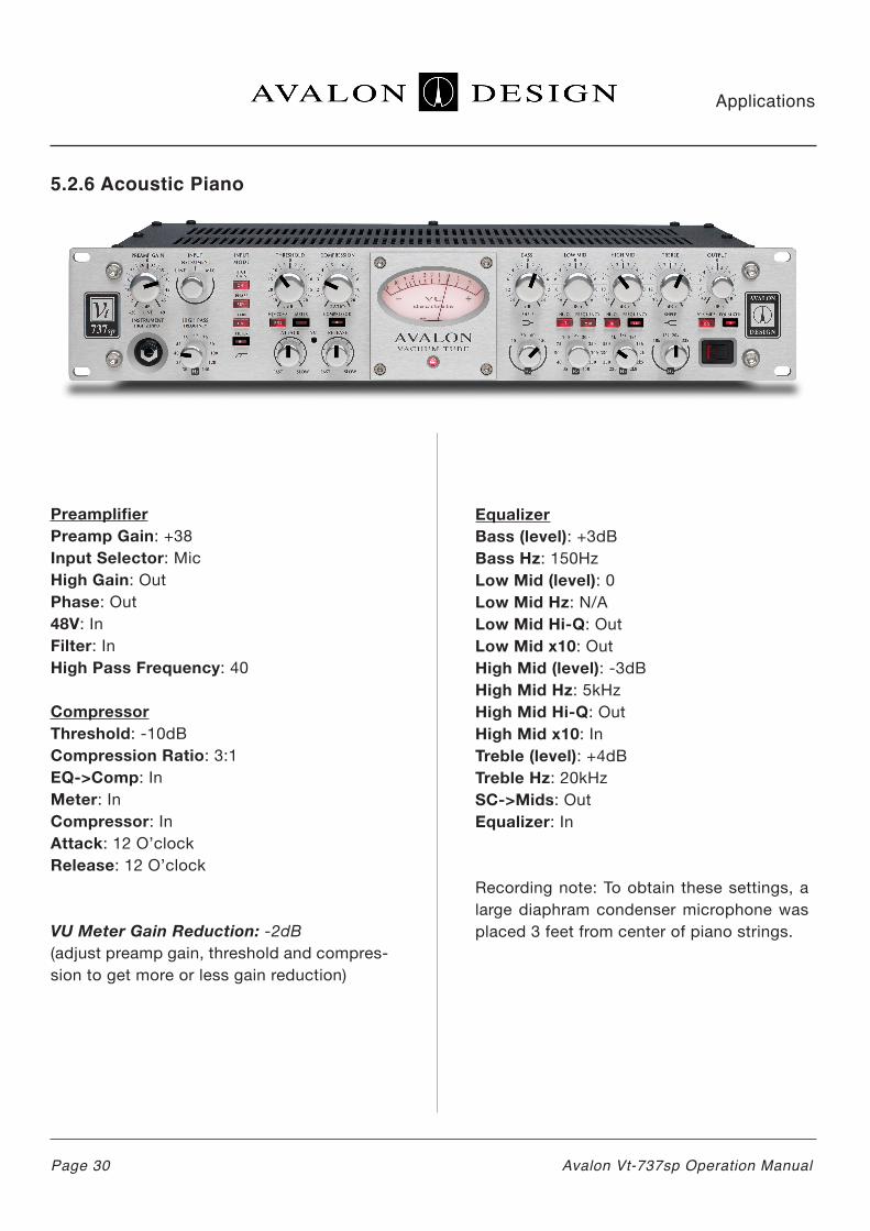
5.2.6 Acoustic Piano
PreamplifierPreamp Gain: +38Input Selector: MicHigh Gain: OutPhase: Out48V: InFilter: In High Pass Frequency: 40
CompressorThreshold: -10dBCompression Ratio: 3:1EQ->Comp: InMeter: InCompressor: InAttack: 12 O’clockRelease: 12 O’clock
VU Meter Gain Reduction: -2dB (adjust preamp gain, threshold and compres-sion to get more or less gain reduction)
EqualizerBass (level): +3dBBass Hz: 150HzLow Mid (level): 0Low Mid Hz: N/ALow Mid Hi-Q: Out Low Mid x10: Out High Mid (level): -3dBHigh Mid Hz: 5kHzHigh Mid Hi-Q: Out High Mid x10: In Treble (level): +4dB Treble Hz: 20kHz SC->Mids: Out Equalizer: In
Recording note: To obtain these settings, a large diaphram condenser microphone was placed 3 feet from center of piano strings.
Applications
Page 30 Avalon Vt-737sp Operation Manual

5.2.7 Snare Drum
PreamplifierPreamp Gain: 0Input Selector: MicHigh Gain: OutPhase: Out48V: Out (dynamic microphone)Filter: OutHigh Pass Frequency: N/A
CompressorThreshold: -7dBCompression Ratio: 3:1EQ->Comp: OutMeter: InCompressor: InAttack: fastRelease: fast
VU Meter Gain Reduction: -3dB (adjust preamp gain, threshold and compres-sion to get more or less gain reduction)
EqualizerBass (level): 0Bass Hz: N/A Low Mid (level): +4dBLow Mid Hz: 250HzLow Mid Hi-Q: InLow Mid x10: Out High Mid (level): +10dBHigh Mid Hz: 14kHzHigh Mid Hi-Q: Out High Mid x10: In Treble (level): +10dB Treble Hz: 20kHzSC->Mids: Out Equalizer: In
Applications
Page 31Avalon Vt-737sp Operation Manual

5.2.6 Drums - Kick Drum
PreamplifierPreamp Gain: +38Input Selector: MicHigh Gain: OutPhase: Out48V: Out (dynamic mic)Filter: In High Pass Frequency: 55
CompressorThreshold: -10dBCompression Ratio: 8:1EQ->Comp: OutMeter: InCompressor: InAttack: fastRelease: fast
VU Meter Gain Reduction: -3dB to -5dB(adjust preamp gain, threshold and compres-sion to get more or less gain reduction)
EqualizerBass (level): +5dBBass Hz: 30HzLow Mid (level): +4dBLow Mid Hz: 100HzLow Mid Hi-Q: In Low Mid x10: Out High Mid (level): +10dBHigh Mid Hz: 5k5HzHigh Mid Hi-Q: Out High Mid x10: In Treble (level): +6dB Treble Hz: 10kHz SC->Mids: Out Equalizer: In
Applications
Page 32 Avalon Vt-737sp Operation Manual

5.2.9 Drum Overheads / Cymbals
PreamplifierPreamp Gain: 0Input Selector: MicHigh Gain: OutPhase: Out48V: InFilter: InHigh Pass Frequency: 40Hz
CompressorThreshold: -7dBCompression Ratio: 4:1EQ->Comp: OutMeter: InCompressor: InAttack: 7 O’clockRelease: slow
VU Meter Gain Reduction: -2dB (adjust preamp gain, threshold and com-pression to get more or less gain reduction)
EqualizerBass (level): 0Bass Hz: N/A Low Mid (level): -4dBLow Mid Hz: 200HzLow Mid Hi-Q: OutLow Mid x10: Out High Mid (level): -2dBHigh Mid Hz: 1k6HzHigh Mid Hi-Q: In High Mid x10: OutTreble (level): +2dB Treble Hz: 32kHzSC->Mids: Out Equalizer: In
Note: Use High Pass Filter to remove kick and tom muddiness.
Applications
Page 33Avalon Vt-737sp Operation Manual
6.0 Basics
This chapter is intended to help the relatively new recording engineer understand many of the basics involved in recording. Included are information on impedance and cables as well as general information on microphones, preamplifiers, compressors, and equalizers. The information does not necessarily apply directly to the Vt-737sp, but many of the topics discussed will help you understand how to better utilize your Vt-737sp.
6.1 Impedance
Impedance is the total effective AC resistance of a circuit, measured in ohms. The impedance of an output or source is a measure of how easily the power will flow (source impedance). The impedance of an input is a measure of how much power that input will tend to draw (load inpedance).
Microphones are divided into two types of impedance: high impedance and low imped-ance. Most professional microphones are low impedance devices, which means that their source impedance is below 600 ohms. Piezo-electric contact pickups, guitar pickups and inexpensive microphones are usually high impedance, meaning that their source imped-ance is 2500 ohms or greater.
Low impedance microphones are preferred in recording and sound reinforcement, since when properly connected, they are far less susceptible to extraneous noise pickup in the cable. Low impedance mics can drive cables hundreds of feet long, whereas high imped-ance mics are limited to about 20 feet.
High impedance microphones and pickups require a transformer or buffer amplifier when they are used with low impedance inputs and/orlong mic cables. In this case, the transformer converts the device’s high impedance to a low impedance suitable for driving the connection.
6.2 Balanced vs. Unbalanced
An unbalanced connection is a two-wire system. One wire carries the audio signal, and the other (called the shield) is connected to ground, or the electrical reference point.
A balanced connection is a three-wire system. Two separate wipes carry the signal - one inverted in polarity with respect to the other - and the third is the shield, which again is connected to ground.
Balanced connections are almost always used for low impedance microphones. The balanced system is less susceptile to noise, and is the preffered method in pro-fessional audio. The most common balanced connector found on pro audio equipment is the three pin XLR-type, which is chosen for several reasons: It has three conductors, it is shielded, it locks in place, and the ground pin makes contact first to bleed static from the cable to avoid pops.
Unbalanced connections are used for high-impedance microphones and pickups, and sometimes for low impedance mics in consumer equipment. The unbalanced system is more susceptible to noise pickup, and is generally not preferred in professional work. The most common unbalanced con-nector is the 1/4-inch phone connector.
Basics
Page 34 Avalon Vt-737sp Operation Manual

6.3 Cables and Connectors
Regardless of how high the quality of your mics, mixing console, singal processors, recording devices and monitors, the entire system can be degraded or silenced by a bad cable. Hum, crackles and lost signal due to open circuits, or failed outputs due to shorted circuits can be caused by cable problems. You should never try to save money by cutting corners with cables or connectors.
High price alone does not guarantee a good product. There are major differences between similar looking cables. All wire is not the same, nor are all look-alike connectors made the same way. Even if the overall diameter, wire gauge and general construction are similar, two cables may have significantly different electrical and physical properties. Resistance and capacitance between conductors, induc-tance, overall flexibility, shielding density, durability, ability to withstand crushing or sharp bends, tensile strength and other factors can vary greatly. More stands usually yield better flexibility and less chance of metal fatigue or failure caused by an inadverten nick in the cable.
Connectors also can differ dramatically. They must be well made, with low contact resis-tance. They should be well secured to the cable, with thoroughly soldered shields and inner conductors plus good strain relief. It is important to routinely check your cables and connectors for broken or nearly broken con-nections.
6.4 Microphones
Microphone is a generic term that is used to refer to any element which transforms
accoustic energy (sound) into electrical energy (the audio signal). Microphone selec-tion and placement during recording is one of the single most important skills a recording engineer can learn. There are generally three main types of microphones used in recording: Dynamic, Condenser and Ribbon micro-phones.
A Dynamic microphone is made up of a flexi-bly mounted diaphragm coupled to a coil of fine wire, with a voice coil mounted in the air gap of a magnet.
When sound strikes the diaphragm, the diaphragm surface vibrates in response. The motion of the diaphragm couples directly to the coil, which moves back and forth in the field of the magnet. As the coil cuts through the lines of magnetic force in the gap, a small electrical current is induced into the wire. The magnitude and direction of that current is directly related to the motion of the coil, and thus is an electrical represensation of the inci-dent sound wave.
Dynamic microphones are not only highly dependable, they are also extremely rugged. For this reason, they are very good for record-ing loud instruments such as drums and elec-tric guitars. Two of the most common dynamic mics used for recording are the Shure SM57 and the Sennheiser 421.
The Condenser microphone is made of a gold-coated plastic diaphragm that is mount-ed above a conductive gold plated ceramic back plate. The diaphragm and back plate, separated by a small volume of air, form an electrical component called a capacitor (also known as a condenser).
Basics
Page 35Avalon Vt-737sp Operation Manual
Condenser microphones are typically more sensitive than dynamic mics and are useful for recording the harmonic details of instruments and voices at lower volume levels such as acoustic guitars, acoustic piano, and vocals. Condensers also typically cover a wider frequency range and pick up the complex harmonics and overtones that come from instruments such as acoustic piano, vocals, horns, xylophone, vibes or cymbals.
Condenser microphones require a polarizing voltage and power for their built-in amplifiers. Sometimes provision is made to supply this voltage directly through the microphone cable. The procedure is called phantom pow-ering, and the most common phantom supply voltage available is 48V. Most phantom pow-ered mics can operate on a wider range of supply voltages from as little as 1.5V up to 50V. A commonly used condenser micro-phone found in many professional recording studios is the Neumann U87 and the AKG C414.
Ribbon mics are constructed with a very light, thin, corrugated metal ribbon that is stretched within the air gap of a powerful magnet. The ribbon is clamped at the ends but is free to move throughout its length. When sound strikes the ribbon, the ribbon vibrates in response. As is the case with the dynamic coil element, the moving ribbon cuts the magnetic lines of force in the air gap, and the voltage is thereby induced in the ribbon.
6.5 Preamplifiers
A preamplifier is used to boost the signal of a low level instrument or microphone to a common usable level such as in a mixing con-sole or recording device.
Most preamplifiers today are built around an integrated circuit called an operational ampli-fier or “op amp”. Op amp preamplifiers are widely used today in mixing consoles and consumer preamplifiers because they are inexpensive and widely available. However op amp preamps distort easily, typically color the sound, and do not retain the entire frequency range of the signal. (Avalon does not use Op amps for audio signal processing.
A high quality preamplifier like the Vt-737sp retains the entire frequency and dynamic ranges of the signal. High quality preamplifi-ers operate in Class A and are made of discrete electronics (no op amps), giving the preamplifier less distortion and purer sound. Avalon takes it a step further by combining Class A mode and discrete electronics with high voltage and high current design which produce higher power rails and more head-room for the biggest and purest sound possi-ble. Avalon’s 100% discrete, Class A pream-plifiers require many specialized components, a large power transformer, heat sinks for heat dissipation and are therefore much more expensive to build than preamplifiers built around op amps.
Basics
Page 36 Avalon Vt-737sp Operation Manual

6.6 Compression
A compressor is one of the most widely used signal processors in the recording studio. Compressors are used during the recording process as well as during mixdown and mas-tering. During the recording process com-pressors are used to control the dynamic range or volume of a signal. For example, a singer may vary his volume level from a whipser to a scream during a particular song. A compressor will control the volume is con-sistent whether the singer is whispering or screaming. During mixdown compressors are used to “tighten up” the tracks so that noth-ing pops out of the mix uncontrollably. During the mastering process compressors are used very slightly to tighten up the entire mix and can give the mix a bigger sound.
The way a compressor works is like an auto-matic fader. When the input signal exceeds a predetermined level called the threshold, the gain is reduced by the compressor and the signal is attenuated. By attenuating the louder signal levels, you are in fact, reducing the program’s overall dynamic range. Because the range between the loudest and softest signal is “compressed” by increasing the signal’s overall gain, the average level will be greater. Thus the signal will be perceived as being louder than it otherwise would be.
Compression is measured by the ratio of the change in output level (in dB) to the change in input level, called the compression ratio. If a compressor is set to 8:1 compression then an 8 dB increase in the input level will result in a 1 dB increase in the output level.
Compression Variables Defined
Most compressors are controlled by four main functions: Threshold, Ratio, Attack, and Release.
Threshold: Defines the level where compres-sion begins. If the sound level coming into the input is below the threshold, the com-pressor won’t do anything. When a louder signal rises above the threshold, the com-pressor starts working, automatically reduc-ing the output gain by the amount set with the ratio control.
Ratio: The ratio control is the amount of volume reduction relative to the original signal level. A 1:1 (one to one) ratio is the lowest compression ratio. This means that the volume that goes into the compressor is exactly the same as the volume that comes out. A 2:1 ratio means that the compressor will only allow the output level to rise 1dB for every 2dB that the input is over the thresh-old. This way the compressor allows the signal to be louder than the louder than the threshold, but only by half as much. This is typical moderate compression. A 4:1 ratio means that if the input signal is 4dB over the threshold, the compressor only allows an output 1dB over the threshold.
Attack: The very beginning of a sound is usually the loudest and most difficult to record smoothly (for example, vocals, slap bass, guitar, etc.). In many cases you want to let these initial transients pass through before pulling down the gain, other times you want the compression to start right away. To help make adjustments to this specific event, the attack control adjusts the length of time it takes for the compression to begin.
Basics
Page 37Avalon Vt-737sp Operation Manual

Release: Once the signal falls below the threshold, the Release control determines how quickly the compressor “lets go” of the volume control and lets the level rise back to unity gain. Just as the Attack control sets the volume of the start of a sound, the Release control sets volume of the end of a sound. The release can be used creatively to make sounds cut-off sharply or sustain longer.
Compressors usually have built-in metering to allow monitoring of the amount of gain reduc-tion taking place. The meter usually sits at 0 VU when the input signal is below the threshold and falls to the left to indicate the number of decibels of gain reduction. Also the actual speed of the moving needle indicates the attack and release speeds.
Graphic Description of Compression
6.7 Equalization
An equalizer is a group of tone controls that allow adjustment to the full frequency range of an incoming signal using a number of sep-arate frequency bands. A parametric equaliz-er consists of frequency selection, gain/cut control, and a bandwidth or “Q” control for each frequency band. A four-band paramet-ric as found in the Vt-737sp consists of four frequency selection controls: BASS, LOW MID, HIGH MID AND TREBLE.
The amplitude or level control adds or sub-tracts volume level within the specified frequency band. The frequency selection control selects the frequency range being adjusted.
The bandwidth or “Q” parameter refers to the narrowness of the effected bandwidth around the specified center frequency. A higher “Q” covers a narrower frequency range.
Equalization TipsHere is a list of instruments and their corre-sponding frequency ranges of interest used for applying equalization during recording.
Vocals - Fullness at 120Hz;boominess at 200Hz to 240Hz;presence at 5kHz;sibilance “ss” at 8kHz to 12kHz;Use High Pass Filter at 30Hz to 100Hz to remove boomy muddiness and room noise.
Acoustic piano - Bottom at 80-120Hz; pres-ence at 2k5Hz to 5kHz;crisp attack at 10kHz
Basics
Page 38 Avalon Vt-737sp Operation Manual
dB
+5dB
Time
Compression Ratio = 5:1Threshold = +5 dB

Keyboard - Bottom at 80Hz to 120Hz; body at 240Hz; presence at 2k5Hz.
Bass guitar - Bottom at 60Hz to 80Hz; attack/pluck at 700Hz to 1kHz;string noise / pop at 2kHz to 3kHz.
Electric guitar - Fullness at 240Hz; bite at 2kHz to 3kHz
Acoustic guitar - Bottom boom at 80-120Hz; body at 240Hz; clarity at 2k5Hz to 5kHz.
Horns - Fullness at 120 to 240Hz; shrill at 5kHz to 8kHz.
Strings - Fullness at 240Hz;scratchiness at 7k5Hz to 10kHz
Kick Drum - Depth at 60 to 80Hz; click attack at 2k5Hz to 8kHz
Snare Drum - Fullness at 250Hz;attack/crack at 5kHz
Hi-hat and cymbals - Gong at 200Hz; shim-mer at 8kHz to 15Hz; Air at 20 to 32kHz;Use High Pass Filter at 140Hz to remove kick drum middiness and bleed through.
Rack toms - Fat at 200 to 250Hz; crack at 5kHz
Floor toms - Fullness at 80 to 120Hz; attack at 5kHz
Conga/Bongo - Resonance at 200Hz to 240Hz; presence/slap at 5kHz
FAQs
Page 39Avalon Vt-737sp Operation Manual
7.0 FAQs
The following are answers to Frequently Asked Questions about the Vt-737sp:
Q: Can I use the Vt-737sp as an insert for compression and EQ?A: Yes. The Vt-737sp is perfect as an insert of a recorded signal such as vocals, guitars, key-boards, acoustic piano, drums, etc. Many engi-neers use their Vt-737sp on their most import-ant track during mixdown.
Q: How often will I need to change the tubes?A: The vacuum tubes on the Vt-737sp are mili-tary spec tubes rated for over 5,000 hours. Avalon recommends changing the tubes approximately every 2 years or so on a unit that is used regularly. Avalon recommends that you replace tubes with exact make and model of the tubes that Avalon specifies. You may purchase a spare set of tubes for your Vt-737sp directly from Avalon.
Q: What is the difference between the Vt-737sp and the Vt-747sp?A: The Vt-737sp is a mono Mic, Line, and Instrument level preamplifier with compressor and parametric equalizer. It is great for record-ing one channel at a time and for mixdown on the most important channel.
The Vt-737sp is a dedicated stereo line level compressor and graphic equalizer. It has no microphone preamplifier. The Vt-747sp is great for stereo keyboards, synthesizers, drum machines, stereo submix or mix buss applica-tions and mastering.
Q: Can I damage the Vt-737sp by turning the preamp gain up too high?A: No. The Vt-737sp has enourmous head-room (+36dB on Line Input). Crank it up and check it out.
Q: Why does Avalon use opto-compres-sors?A: Avalon uses opto-compressors because they are the most musical of all compressor types.
Q: Can I do mastering with a pair of Vt-737sp’s?A: Yes. The Link jack in the back enables you to link the compressors of two Vt-7337sp’s. You will have to adjust the EQ controls sepa-rately on each unit. The noise floor is low enough for mastering and EQ is definitely sweet enough. Avalon recommends either the AD2044 compressor and AD2077 (or AD2055) equalizer for professional mastering. Also the Vt-747sp is wonderful for project studio mas-tering since it is a dedicated stereo unit.
Q: Is the Vt-737sp durable enough for the road?A: Yes. The Vt-737sp as well as all Avalon equipment is literally “built like a tank”. Steel chassis, metal faceplate, metal knobs, all circuit boards are screwed to chassis, etc.
Q: Should I power down the Vt-737sp?A: The Vt-737sp is equipped with a “soft-start” procedure that slowly brings the unit to life without damaging the tubes. Avalon recom-mends that you turn the unit off if not being used for more than 4 hours. This procedure will also save on your electric bills.
Q: Will the Vt-737sp continue to work when I travel to different countries?A: Yes. The power supply on the Vt-737sp has selectable voltages: 100V, 120V, 220V, and 240V. It is very easy to change the voltage. See Chapter 3 (page 13).
Q: Why does the needle in the VU meter drift to the left of 0dB after the Vt-737sp warms up?A: As the unit warms up, after approximately 30 minutes, the resistance of the meter coil is increased with heat and the needle then settles into its opening 0dB position (just like the old LA2A’s). To calibrate the VU meter to 0dB see page 44.
Q: Will the Vt-737sp work with my unbal-anced inputs on my recording device?A: Yes. You need to make sure that the cables you are using are wired the same (pin 2 hot). You can get a cable that has XLR on one side and RCA or 1/4” on the other. This will work fine for the unbalanced system, as long as the cables are not over 10ft in length.
Q: Will the Vt-737sp work if it is going into a recording device that is designed for -10dB operation?A: Yes. The Vt-737sp will work however the signal coming from the Vt-737sp may be too hot of a signal and you may need to turn down the output control so that the signal more closely matches the -10dB machine. If you have a choice, you should always run at +4dB.
Q: Can I try using different types of tubes in the Vt-737sp to get different or better sounds?A: Avalon has selected the tubes in your Vt-737sp for optimal sonic performance.
FAQs
Page 40 Avalon Vt-737sp Operation Manual

Avalon does not recommend that you exper-iment with different types of tubes because it can lead to extreme damage to your Vt-737sp.
Q: If I am using a digital recording system, is it worth going out of my digital system for mixdown and mastering even if I don’t have to?A: Yes. The Vt-737sp is known to breath life into digital recordings. It will add air to the highs and open up the bottom end. This pro-cess is very effective if you have high quality A to D and D to A converters. If your con-verters are not of the highest quality it will still be beneficial. Try it.
Q: What kind of microphones work best with the Vt-737sp?A: The Vt-737sp was designed to work with all types of microphones. (ie condensers, dynamics, etc.) It works great with FET con-densers as well as tube condensers. Micro-phone choice and selection is a matter of taste.
Q: Can I use the Vt-737sp live as a micro-phone preamp? As a DI box?A: Yes. Many touring artists are currently using the Vt-737sp as vocal mic preamp as well as a preamp for bass and guitars. And since it is literally built like a tank it will with-stand the rough conditions of the road.
Q: Will the Vt-737sp help to warm up the signal going to a digital recorder?A: Yes. The Vt-737sp will give the signal a richer warmer sound. The bottom end will open up and your recorded signal will sound bigger. It works wonderfully on digital recordings that would otherwise sound thin and lifeless.
Q: What are the main difference between the Vt-737sp’s mic preamp and Avalon’s AD2022 or M5 mic preamps?A: The Vt-737sp is a vacuum tube preamp with compression and equalizer. The AD2022 (dual channel), and M5 (mono) are traditional ultra-high performance mic preamps made with discrete electronics and not tubes. All Avalon Design preamps run in Class A mode and feature enormous headroom and wonderful musicality. Sonically, the Vt-737sp has a more “close-up” sound whereas the AD2022 and M5 have a large and deeper sound stage giving a three dimensional image. The type of preamp you choose is a matter of taste.
Q: What’s the main difference between the Vt-737sp’s compressor and the AD2044 com-pressor?A: The Vt-737sp is a single channel, mono com-pressor that is loaded with many different tones and color. The Vt-737sp has vacuum tubes, four band parametric EQ and built in side-chain. The AD2044 is an ultra high performance traditional dual mono compressor using all discrete pure Class A electronics (no tubes). It features extreme dynamic range, low noise and traspar-ent compression, perfect for tracking, mixing, and mastering.
Q: What’s the main difference between the Vt-737sp’s EQ and the AD2055 EQ?A: The four-band parametric equalizer on the Vt-737sp is similar in operation to one channel on the AD2055 equalizer. The dual channel AD2055 is a line level EQ with variable Q control in the mid-bands, greater lower frequency con-trol, ultra-smooth highs and low noise. The AD2055 has been labeled as arguably the best sounding equalizers ever built.
FAQs
Page 41Avalon Vt-737sp Operation Manual

8.0 Trouble Shooting
If you experience any problems with your Vt-737sp, please make sure to first isolate the problem to your Vt-737sp. In many cases the problem can be a bad cable instrument, or another piece of equipment in the signal path.
It is easiest to isolate the problem by removing as many pieces of extraneous gear in the signal path as possible. If you believe that your Vt-737sp has problem, please set up the following test system:
1. Plug your input source (microphone, instru-ment or line input) into Vt-737sp; make sure to check your cable.
2. Output of Vt-737sp directly to powered monitors or monitor system. Use the OUTPUT control on the Vt-737sp to adjust volume and check this cable as well.
Once you have isolated the problem to the Vt-737sp please check the following list of problems and corresponding suggested solu-tions.
Trouble Shooting
Page 42 Avalon Vt-737sp Operation Manual
Problem Cause SolutionNo power Power cable on back of chassis not
securely plugged inCheck cable
No power Fuse blown due to power surge orimproper AC voltage setting
Replace fuse and check AC voltagesetting (page 13)
No sound XLR cable not in correct input on back of unit (Microphone, Line)
Check that input cable is plugged into intended input
No sound +48v not on for a microphone thatrequires phantom power
Press in +48v to supply microphonewith phantom power
Distorted sound Microphone or input source overloading
Try a different microphone or input source;adjust input preamp gain
Distorted sound Vt-737sp may be overheating Make sure Vt-737sp has proper ventalation (page 14)
Hum or buzzing noise
Bad cables or ground loop Check all cables and grounding system; lift ground on Vt-737sp (page 13)
Overloadingrecording device
Recording device is -10dB device, Vt-737sp is +4dB device
Turn down output control on Vt-737sp to adjust to usable recording level
No sound Bad cable Check cables
Lights dim /no sound
Improper AC voltage setting Check AC voltage setting (page 13)
No sound Input selector set in wrong position Make sure input selector switch is set tothe physical input that you are using (Mic,Instrument, Line)

1. Plug your input source (microphone, instru-ment or line input) into Vt-737sp; make sure to check your cable.
2. Output of Vt-737sp directly to powered mon-itors or monitor system. Use the OUTPUT con-trol on the Vt-737sp to adjust volume and check this cable as well.
Once you have isolated the problem to the Vt-737sp please check the following list of problems and corresponding suggested solu-tions.
Tube Related Symtoms
The following list are symptoms of a failing vacuum tube. If you are experiencing these symptoms please call your local dealer or the Avalon factory at 949-492-2000 or visit www.avalondesign.com
1. Background noise (a crackling or sizzling sound)
2. Ringing noise
3. Low output volume
4. Distorted sound
For more information on tubes see page 44.
Trouble Shooting
Page 43Avalon Vt-737sp Operation Manual

9.0 Service and Contact Information
Maintenance and Tube LifeBecause of the exceptional build quality of the Vt-737sp, the unit will perform for many years to come. But just like any musical instrument, it needs care and maintenance to keep it in top shape.
Vacuum Tube ReplacementFor peak performance, Avalon Design recom-mends changing these tubes every 5000 hours of run time. Selected, performance-matched vacuum tubes are available directly from the factory. This breaks down to approximately changing the tubes every two years assuming use of 8 hours per day, 7 days per week. A matched set of replacement tubes can be purchased directly from your local dealer or Avalon. Avalon only recommends Sovtek 6922 vacuum tubes for your Vt-737sp. Replacement of tubes should be performed by an authorized Avalon technician.
Meter Calibration and AlignmentThe VU meter can be easily adjusted to 0 VU when no signal is present. To adjust the VU meter to zero:1. Turn the unit on2. Let unit warm up for at least 30 minutes3. Unplug all inputs4. From the front of the unit use a small flat head screwdriver to turn the recessed trim pot so that the needle reads zero.
External CleaningThe Vt-737sp can be cleaned using an ordinary mild house cleaner such as 409 or Windex. Do not use abrasive cleaners or petroleoum-based solvents. Doing so could cause damage to the finish.
Contact InformationAvalon Design3715 Cahuenga Blvd.Studio City, CA 91604
Tel: 949-492-2000
Email: [email protected]
Website: www.avalondesign.com
Service Information
Page 44 Avalon Vt-737sp Operation Manual

10.0 Technical Information
Your Vt-737sp is built to withstand many years of high performance music making. If you expe-rience any malfunctions or problems, please contact the dealer where your unit was purchased. If your Vt-737sp has outlasted your dealer, please contact Avalon.
Specifications
Circuit Topology: Four dual triode vacuum tubes, high-voltage discrete Class A
Gain Range: Microphone: Transformer balanced, 850 ohms input impedance, 0dB to+58dB Instrument: Unbalanced 1 meg ohm input impedance, 0dB to +30dB Line: Balanced, 20k ohms input impedance, -27dB to +18dB
Maximum input level and connectors: Microphone: +16dB @ 25Hz, +30dB @ 1kHz balanced XLR, pin 2 hot Instrument: +30dB unbalanced front panel jack socket Line: +36dB balanced XLR, pin 2 hot
Maximum output level: +30dB balanced XLR 600 ohms output impedance, DC coupled, pure Class A
Output type: XLR connector, output trim gain -45dB to +10dB
Noise 20-20kHz unweighted: -92dBuDistortion (THD, IMD) @ 1kHz: 0.5% Unit Bandwidth: 1 to 200kHzFrequency Response: 10 to 40kHz +/-0.2dBVU meter and gain reduction: 0VU=+4dBu and gain reduction to -20dB.
Hi-cut filter: Variable 6dB per octave 40Hz to 200Hz
Compressor type: optical passive attenuator incorporating twin vacuum tubes and stereo link
Compression ratio: Variable 1:1 to 20:1Threshold: Variable -30dB to +20dBAttack: Variable 2mS to 200 mSRelease: Variable 100mS to 5 seconds
Equalizer type: Discrete Class A, variable active and switched passive design
Frequency bands (4): Treble - switched 10kHz, 15kHz, 20kHz, 32kHz, +/-20dB range, shelf High Mid - variable 200Hz to 2k8Hz, and 2kHz to 28kHz, +/-16dB range, hi-low Q Low Mid - variable 30Hz to 450Hz, and 3kHz to 4k5Hz, +/-16dB range, hi-low Q Bass - switched 15Hz, 30Hz, 60Hz, 150Hz, +/-24dB range, shelf
AC power: Internal toroidal 100V to 240V, 50-60Hz selectable, 60 watts maximum, enclosed in separate steel chassis
Dimensions: 19 x 12 x 3.5 inches 482 x 305 x 89mm
Weight: 22 lbs. (10kg)
Dimensions - shipping carton:21 x 18 x 8 inches533 x 457 x 203 mm
Weight packed: 26 lbs. (11.8kg)
Technical Information
Page 45Avalon Vt-737sp Operation Manual

10.1 Vt-737sp Recall Sheet
TechnicalInformation
Page 46 Avalon Vt-737sp Operation Manual

10.2 Vt-737sp Block Diagram
TechnicalInformation
Page 47Avalon Vt-737sp Operation Manual

10.3 Vt-737 (purple) vs Vt-737sp
As of Jaunary 1999 the original Vt-737 was discontinued and is no longer in production.
There are three main differences between the original Vt-737 (purple knobs) and the Vt-737sp (Special Performance). All other components are identical including the circuit boards.
KnobsVt-737: Purple Plastic
FaceplateVt-737: Purple and black printing Vt-737sp: Black photo-etched, more detailed
Mic input transformerVt-737: quality mic input transformerVt-737sp: larger mic input transformer
Upgrades from Vt-737 to Vt-737sp are available. Please call your local dealer or Avalon at 949-492-2000 for details.
11.0 Warranty
Avalon Industries, Inc. warrants this product against deflects in material or workmanship as follows:1. For a period of time (1) year from the date of purchase Avalon will pay the labor charges to repair the defective product. After this one (1) year period, all labor charges will be paid by the customer. 2. Avalon will supply at no charge, new or rebuilt replacements for any defective mechanical switches, potentiometers or moving parts for a period of one (1) year from original date of purchase. 3. Avalon will supply at no charge, new replace-ment for any defective vacuum tubes for a period of ninety days (90) from the original date of purh-case. 4. This warranty is void if the product has been found to be subjected to misuse, abuse or una-thorized service. 5. This warranty does not cover cosmetic damage, and damage due to acts of God, acci-dent or transit damage. 6. Proof of purchase in the form of a bill of sale or invoice to provide evidence that the unit is within the warranty period must be presented to obtain warranty service. 7. This warranty is only valid if the serial number appears on the product.
Outside of the USA
Please check www.avalondesign.com for your nearest authorized service center.
Warranty andSafety Standards
Page 48 Avalon Vt-737sp Operation Manual
Vt-737 (top) Vt-737sp (bottom)
11.1 Returns
If you Vt-737sp has become defective within the one (1) year period as specified above, please contact the place of purchase to arrange for war-ranty repair. If you would rather directly with Avalon, please call the factory at 949-492-2000.
To return a unit to Avalon for repair or exchange you will need to obtain a Return Authorization Number (RA) from Avalon.
To obtain an RA number (in the USA only)1. Visit www.avalondesign.com and submit a “request for service” form 2. Once submitted, our service department will contact you with an RA number.
Do not send your unit to Avalon without an RA number.
12.0 Safety Standards
Avalon Industries, Inc. declares that the Vt-737sp conforms to standards EN55013 (Emissions), EN55020 (Immunity), and EN60065 (Product Safety).
Warranty and Safety Standards
Page 49Avalon Vt-737sp Operation Manual

Appendix A - Glossary
amplification - The process by which a signal level is increased.
amplitude - The distance above or below the centerline of a signal’s waveform. The greater the distance from the centerline, the larger the pres-sure variation or electrical signal.
attack - The initial transient or first part of the envelope of a signal. The beginning of a note.
attenuate - To reduce the signal level.
balanced - In a classic balanced audio circuit, the two legs of the circuit (+ and -) are isloated from the circuit ground by exactly the same imped-ance. Additionally, each leg carries the signal at exactly the same level but with opposite polarity. Balanced input circuits can offer excellent rejec-tion of noise and grounding loops.
balanced line - A cable having two conductors and a ground connection and often surrounded by a shield. With respect to ground, the conduc-tors are at equal potential but opposite polarity. These lines are often used in professional setting to reduce or eliminate induced noise and interfer-ence from external electromagnetic sources.
bandwidth - The band of frequencies that pass through a device with a loss of less than 3dB, expressed in hertz or in musical octaves.
cardioid - Refers to the shape of the sensitivity pattern of certain directional microphones.
channel - A single functional path in an audio circuit.
clipping - A cause of audio distortion that is the result of excessive gain requiring the peaks of the audio signal to rise above the capabili-ties of the circuit.
compressor - In effect, an automatic fader. When the input signal exceeds a predeter-mined level, called the threshold, the gain is reduced by the compressor and the signal is attenuated.
compression ratio - The ratio of signal dynamic range between the compressor input and the outupt above the device’s set thresh-old point (such as 2:1, 4:1, 20:1).
condenser - Refers to a type of microphone that uses a capacitor as the sound pickup element. Condenser mics require electrical power to run internal amplifiers and maintain an electrical charge on the capacitor. They are typically powered by internal batteries or “phantom power” (48v) supplied by an external source, such as a preamplifier or mixing con-sole.
console - A term for a sound mixer, usually a large desk-type mixing board used to mix together multiple track musical material.
crosstalk - The unwanted leakage of a signal from one channel or track onto another.
decibel (dB) - A unit of audio measurement of sound pressure level (SPL), signal level, and changes of difference in signal level. The deci-bel is a logarithmic (log) mathematical function that reduces large numeric values into smaller, more manageable numbers. Decibel is calcu-lated as 10 times the log of the ratio of two powers, and 20 times the log of the ratio of two voltages.
Glossary
Page 50 Avalon Vt-737sp Operation Manual

Glossary
Page 51Avalon Vt-737sp Operation Manual
dBm - Decibels referenced to 1 milliwatt.
dBu or dBv - Decibels referenced to 0.775 volt.
dBV - Decibels referenced to 1 volt.
de-ess - Using a frequency-dependent function in a compressor to reduce excessive sibilance (”sss, “sh”, and “ch”) sounds.
detent - A point of slight physical resistance (a click stop) in the travel of a knob or slide control.
dynamic microphone - A microphone that operates by electromagnetic induction to gener-ate an output signal. When an electrically con-ductive coil of wire or ribbon is made to cut across the flux lines of a magnetic field, a current of specific magnitude and direction is generated within that coil or ribbon.
dynamic range - The range between the maxi-mum and minimum sound levels of an audio system. It is usually expressed in decibels as the difference between the level at peak clipping and the level of the noise floor.
equalizer - A frequency-dependent amplifier that controls the relative amplitude of various frequencies in the audible bandwidth. The equal-izer lets you exercise tonal control over the harmonic content or timbre of a sound.
EQ curve - A graph of the response of an equal-izer, with frequency on the x (horizontal) axis and amplitude (level) on the y (vertical) axis. Equaliz-er types and effects are often named after the shape of the graphed response curve, such as peak, dip, shelf, notch, knee and so on.
fade - A slow change in volume.
fader - A linear attenuation device or linear volume control.
feedback - The returning of a loudspeaker signal back into a microphone feeding the loud-speaker. Excessive feedback results in unpleas-ant, screaming sounds usually at particular, high frequencies.
filter - A simple equalizer designed to remove certain ranges of frequencies. A high-pass filter (also called a low-cut filter) reduces or elimi-nates frequencies below the cutoff frequency. There are also high-cut (low-pass) filters, band-pass filters, which cut both high and low frequencies but leave a band of frequencies in the middle untouched, and notch filters, which remove a narrow band but leave the high and low frequencies alone.
flanging - A process whereby a delayed signal is combined with itself undelayed. The delay is varied to create continual changes in sound.
frequency - The rate at which a sound wave repeats a cycle. The number of cycles that occurs over the period of one second is called hertz (Hz). Often, the perceived range of hearing is from 20Hz to 18,000Hz.

gain - The measure of how much a credit ampli-fies a signal. Gain may be stated as a ratio of input to output values, such as decibels from line amplifier.
gain stage - An amplification point in a signal path, either within a system or a single device. Overall system gain is distributed between the various gain stages.
graphic EQ - A type of equalizer where the frequency bands for cut/boost and bandwidths are fixed. Graphic EQs are usually controlled by faders instead of knobs.
ground - The point of zero voltage in a circuit or electrical system.
ground loop - A condition that exists in a n improper grounding situation, whereby a DC current differential exists between one signal path and another, resulting in a 50Hz or 60Hz hum.
headroom - The difference between nominal operating level and peak clipping in an audio system.
hertz - The unit of measure for frequency of oscillation, equal to 1 cycle per second. Abbre-viated Hz. kHz is an abbreviation for kilohertz, or 1000 Hertz.
impedance - The opposition of current flow in a circuit.
knee - A sharp bend in an EQ response curve. Also used in describing dynamic processors.
line level - A signal level that is referenced to either +4dB (professional) of -10dB (semi-pro/-consumer).
mastering - The processing and transfer of a final, sequenced or mixed audio tape to a medium for duplication.
mic level - The typical level of a signal from a microphone. A mic level signal is generally below -30dBu. With a very quiet source the signal can be -70dBu or lower.
mic preamplifier - An amplifier that functions to bring the very low level of a microphone up to line level (approximately) +4dBu in professional equipment and -10dB in consumer equipment).
mixdown - The process in which the separate audio tracks of a multiple track recording are combined, balanced, and routed through the recording console. During mixdown, volume, tone, special effects and spatial positioning can be artistically set by the engineer to create a stereo or surround sound mix that is then record-ed to a master recording device, such as a DAT recorder.
monaural - Confined to a signal channel. One microphone is a mono pickup; many micro-phones mixed to one channel is a mono mix. Several mono sources, however, can be panned into a stereo (or at least two-channel) mix.
mono - Short for monaural.
noise - Unwanted sounds. Hum, buzz or hiss; could be crosstalk or digital hiss.
noise floor - The residual level of noise in any system. The lower the noise floor and the higher the headroom, the more usable dynamic range a system has.
Glossary
Page 52 Avalon Vt-737sp Operation Manual

Glossary
Page 53Avalon Vt-737sp Operation Manual
overload - The distortion that occurs when an applied signal exceeds a system’s maximum input level.
parametric EQ - A parametric EQ allows contin-uous control of each of the three primary EQ parameters (frequency, gain and bandwidth) independently.
peak amplitude - The maximum instantaneous amplitude of a signal.
phantom power - Power for a condenser mic from a preamplifier supplying a positive DC supply voltage of +48V through a balanced XLR mic cable.
phase - The degree of progression in the cycle of a wave, where one complete cycle is 360 degrees. Phase is measured in degrees of a cycle (divided into 360 degrees) and will result in audible variations of a combined signal’s ampli-tude and overall frequency response.
phase shift - The difference in degrees of phase angle between corresponding points on two waves.
potentiometer (pot) - A rotary gain, pan, or other type of continuously variable signal control.
preamplifier - A piece of equipment that boosts the signal level so that the signal operates at a higher and more desired level enabling greater frequency and dynamic range.
release time - Once compression has begun, the time taken for the attenuated signal to return to 63% of its original (uncompressed) level.
resistance - The opposition to the flow of DC current in a wire or circuit.
ribbon microphone - A microphone that uses a diaphragm of extremely thin, aluminium ribbon suspended in a strong field of magnetic flux. As sound-pressure variations displace the metal diaphragm in accordance with air-particle velocity, the ribbon cuts across the magnetic lines of flux. This induces a current in the ribbon of proportional amplitude and frequency to the acoustic waveform.
shelving filter - A rise or drop in frequency response at a selected frequency that tapers off to a preset level and continues at the level to the end of the audio spectrum.
side chain - A function on a compressor where a specified frequency range is compressed more than the overall compression of a musical program. Many compressors have a jack so that an equalizer can be inserted into the com-pressor so that whatever frequency bands are boosted on the equalizer, the compressor com-presses the boosted bands more than the over-all compression.
spectral control - The use of a side chain in a compressor to compress selected frequencies of a musical program. One example of spectral control is removing the “sss” sound of a vocal (de-essing).
sweet EQ - An equalizer that allows you to “sweep” or continuously vary the frequency of one or more sections.

unbalanced - An electrical circuit in which the two legs of the circuit are not balanced with respect to ground. Unbalanced circuit connec-tions require only two conductors (signal “hot” and ground). Unbalanced audio circuitry is less expensive to build, but under certain circum-stances is more susceptible to noise.
unbalanced line - A cable having only one con-ductor plus a surrounding shield, in which the shield is at ground potential. The conductor and the shield carry the signal.
volume - Electrical or sound level in an audio system.
waveform - A graph of a signal’s sound pressure or voltage level versus time.
Glossary
Page 54 Avalon Vt-737sp Operation Manual

Glossary
Page 55Avalon Vt-737sp Operation Manual

Glossary
Page 56 Avalon Vt-737sp Operation Manual

Avalon Industries, Inc., 3715 Cahuenga Blvd. Studio City, CA 91604Tel: 949-492-2000 www.avalondesign.com