
VSWR Measurement
5
VS W WR Meas sur r e eme ents Using I In-L L i ine P Pow w e er M Me et e ers By Tim Holt Bird Technologies Group Director, Systems and Applications Engineering 1 | Bird Technologies Group 866.695.4569 www.bird-technologies.com Introduction The measurement of Voltage Standing Wave Ratio (VSWR) has long been considered to be the most universal indicator of the health of transmission systems, and the continuous monitoring of transmission system VSWR, from the output of the transmitter to the input to the antenna is an important component in the maintenance of any wireless communication system. While it is possible to use precision reflection measurement instruments such as vector network analyzers to make high quality measurements on inactive systems, the day to day continuous monitoring of system VSWR under operating conditions typically is performed through the use of in-line directional measurement devices. The best results when using in-line measurement techniques are obtained through the careful management of specific measurement system components and parameters. In this article, we will outline the most important considerations when using in-line VSWR measurement approaches, as well as to provide some recommendations as to the application of these techniques. While we could spend s ignificant time exploring the definition and the supporting mathematics associated with VSWR measurements, the focus of this article will be on the practical details associated with performing continuous measurements on a day to day basis. VSWR Defined - By way of definition, VSWR is a measurement of the ratio of the maximum voltage of a standing wave pattern on a transmission line to the minimum voltage on the line. The s tanding wave pattern is developed as a result of the interaction of the forward traveling wave with the reflected traveling wave, where the magnitude of the re flected traveling wave is related to the degree to which the load is mismatched to the characteristic impedance of the transmission system. (see Figure 1) Figure 1 In-Line Measurements- As mentioned above, the most common technique used today for the ongoing maintenance of broadcast communication networks for routine VSWR measurements is to derive VSWR measurements from direct measurement of the forward and reflected traveling wave (forward and reflected power) using in-line directional power meters. This technique has been used for over sixty years with good results, particularly in c ases where the directional power meters are ca refully selected for specific applications according to signal type, frequency, and power range. While this technique is well established, there are several important considerations when making these measurements that will help to insure high quality measuremen ts. Some of these are: 1) Power Meter Accuracy - What is the basic accuracy of the directional power meter to be used? 2) Power Meter Dynamic Range - Over what range of power measurements will the instrument maintain rated accuracy? 3) Power Meter Directivity - What is the directivity of the directional coupler which forms the heart of the power meter system? 4) Signal Type - What are the characteristics of the signals that are being measured? 5) Location - Where is the power me ter located within the transmission system?
-
Upload
sheraz-tariq -
Category
Documents
-
view
254 -
download
0
Transcript of VSWR Measurement

8/4/2019 VSWR Measurement
http://slidepdf.com/reader/full/vswr-measurement 1/5
VVSSWWRR MMeeaassuurreemmeennttss UUssiinngg IInn--LLiinnee PPoowweerr MMeetteerrss
By Tim HoltBird Technologies Group Director, Systems and Applications Engineering
1 | Bird Technologies Group866.695.4569www.bird-technologies.com
Introduction
The measurement of Voltage Standing Wave Ratio(VSWR) has long been considered to be the mostuniversal indicator of the health of transmissionsystems, and the continuous monitoring oftransmission system VSWR, from the output of thetransmitter to the input to the antenna is an importantcomponent in the maintenance of any wirelesscommunication system. While it is possible to useprecision reflection measurement instruments such asvector network analyzers to make high qualitymeasurements on inactive systems, the day to day
continuous monitoring of system VSWR underoperating conditions typically is performed through theuse of in-line directional measurement devices. Thebest results when using in-line measurementtechniques are obtained through the carefulmanagement of specific measurement systemcomponents and parameters. In this article, we willoutline the most important considerations when usingin-line VSWR measurement approaches, as well as toprovide some recommendations as to the applicationof these techniques. While we could spend significanttime exploring the definition and the supportingmathematics associated with VSWR measurements,the focus of this article will be on the practical detailsassociated with performing continuous measurements
on a day to day basis.
VSWR Defined - By way of definition, VSWR is ameasurement of the ratio of the maximum voltage of astanding wave pattern on a transmission line to theminimum voltage on the line. The standing wavepattern is developed as a result of the interaction ofthe forward traveling wave with the reflected travelingwave, where the magnitude of the reflected travelingwave is related to the degree to which the load ismismatched to the characteristic impedance of thetransmission system. (see Figure 1)
Figure 1
In-Line Measurements- As mentioned above, themost common technique used today for the ongoingmaintenance of broadcast communication networksfor routine VSWR measurements is to derive VSWRmeasurements from direct measurement of theforward and reflected traveling wave (forward andreflected power) using in-line directional powermeters. This technique has been used for over sixtyyears with good results, particularly in cases wherethe directional power meters are carefully selected forspecific applications according to signal type,
frequency, and power range. While this technique iswell established, there are several importantconsiderations when making these measurementsthat will help to insure high quality measurements.Some of these are:
1) Power Meter Accuracy - What is the basicaccuracy of the directional power meter to beused?
2) Power Meter Dynamic Range - Over whatrange of power measurements will the instrumentmaintain rated accuracy?
3) Power Meter Directivity - What is the directivityof the directional coupler which forms the heart ofthe power meter system?
4) Signal Type - What are the characteristics of thesignals that are being measured?
5) Location - Where is the power meter locatedwithin the transmission system?

8/4/2019 VSWR Measurement
http://slidepdf.com/reader/full/vswr-measurement 2/5
VVSSWWRR MMeeaassuurreemmeennttss UUssiinngg IInn--LLiinnee PPoowweerr MMeetteerrss
By Tim HoltBird Technologies Group Director, Systems and Applications Engineering
2 | Bird Technologies Group866.695.4569www.bird-technologies.com
Power Meter Accuracy - When using a directionalpower meter (reflectometer) for VSWR measurement,the VSWR value is based upon the values of forwardand reflected power according to the followingformula:
Pf
Pf VSWR
Pr1
Pr1
−
+
=
Where, PR and PF are values of forward and reflectedpower as determined by the power meter. Basedupon the above formula, it is clear that the basicaccuracy of the power meter will have a direct effectupon the VSWR measurement. In addition, the powermeter accuracy must be considered over the entiredynamic range of the instrument, rather than simplythe accuracy of the power meter at a single point. It isbest to use an example to illustrate this point:
The accuracy statements of most directional power
meters are based upon either a percentage of the fullscale range of the instrument, or as a percentage ofthe actual reading as determined by the power meter.For example, if a particular power meter is specifiedto have a 1 kW full scale forward power range, andthe rated accuracy of the instrument is +/-5% of fullscale, the possible error of the instrument at full scalewould be +/-50W, meaning that the instrument couldprovide a reading between 950W and 1050W andremain within rated specifications. Using the sameapproach, if the power meter is operated at 500W theerror would remain at +/-50W, and the readings couldbe anywhere between 450W and 550W, whichtranslates to an error of +/-10%. Since the VSWRmeasurement is comprised of both forward and
reflected readings, the accuracy of the reflectedpower measurement must also be considered. In ourexample, our 1kW power meter mentioned abovemight use a reflected power range of 100W full scale,again with a rated accuracy of +/-5% of full scale. Asin the case of the 1 kW forward channel, the accuracy
of the measurement at full scale is +/-5%, but thiserror expands to a value considerably greater than +/-5% for downscale readings.
To illustrate the effect that power meter accuracy hasupon VSWR measurement, consider the followingexample:
Again considering our 1 kW transmitter system, if wedesire to measure a load VSWR of 1.1 with the powermeter described above, this would mean that thereflected power associated with this VSWR valuewould be 2.26W if the forward power is 1 kW. If ourpower meter has a specified accuracy of +/-5% of full
scale, the actual VSWR reading will range from 1.09 on the low side, to 1.19 on the high side based uponinstrument accuracy alone. This condition improvesconsiderably with later generation power meters,where the accuracy of the power meter is specified asa percentage of reading, rather than a percentage offull scale. In large part, this has been made possiblethrough the use of square law diode detectortechniques, which behave linearly with respect topower. (see Table 1)
VSWR RANGE FOR POWER METER TYPES VSWR = 1.1
Instrument
Specifications
Reflected Power
Range (W) VSWR Range
% Full Scale 0 to 7.26 1.00-1.19
% Reading 2.15 to 2.37 1.09-1.10
Table 1
Power Meter Dynamic Range - The dynamic rangeof a directional power meter is defined as the range ofpower values over which the instrument is capable ofresolving measurements, while maintaining full ratedaccuracy. It is important to note that in most cases,power meters used for broadcast applications areconfigured as full two channel instruments, with
separate channels for incident and reflectedmeasurements. Often, the full scale power ranges ofeach channel are tailored to specific measurementconditions. For the forward channel, the power rangeis selected based upon 80 to 90% of the transmitteroperating power. The reflected channel full scale

8/4/2019 VSWR Measurement
http://slidepdf.com/reader/full/vswr-measurement 3/5
VVSSWWRR MMeeaassuurreemmeennttss UUssiinngg IInn--LLiinnee PPoowweerr MMeetteerrss
By Tim HoltBird Technologies Group Director, Systems and Applications Engineering
3 | Bird Technologies Group866.695.4569www.bird-technologies.com
power is normally based upon the anticipatedreflected power as it applies to the expected VSWR ofthe antenna system. There is however, a limitation tothis approach based upon the maximum powerhandling capability of the directional coupler / detectorcircuit. For example, if a power meter is to be selectedfor a 20kW transmitter application and the expectedantenna VSWR is 1.1, this would imply that theanticipated reflected power would have a value ofapproximately 46W. For this reason, it would makesense to set the full scale range of the reflectedchannel to 100W, so that the expected reflectedpower could be easily resolved.
Directional Power Meter Directivity - At the heart ofevery in-line, directional power meter is a directionalcoupler for the purpose of providing a sample of thetransmission line voltage, while discerning betweenthe forward and reflected traveling wave.
The directivity parameter for the couplers is ameasure of how well the coupler is capable ofdiscerning between the energy traveling toward theload, and the energy that is being reflected due tomismatch of the characteristic impedance of thetransmission system with the impedance of the load.The directional characteristics of these couplers are aresult of the fact that the coupler extracts two samplesof the energy in the transmission line. One sample isderived from the electric field within the line, and theother is derived from the magnetic field. Thedirectional nature of the magnetic field providesdirectionality, but the electrical balance between themagnetic field and the electric field samples serves asan indicator of the coupler directivity. The morebalanced these samples are, the higher the intrinsicdirectivity of the coupler. Generally, directionalcouplers that are not fitted with frequencycompensation networks have higher directivity, as thecompensation networks are always reactive in nature,and will tend to alter the phase response of thecoupler. These couplers will of course have anarrower operating frequency range.
As a first order approximation, the directivity value ofa coupler may be used to determine the lower limit ofthe reflected power that a particular directional powermeter is able to resolve. This is based upon the factthat although the reflected directional coupler isoriented such that it will respond only to the reflected
traveling wave, it will also be affected by the forwardtraveling wave, in accordance with its directivity. Forexample, using our 20 kW transmitter example, if weare using a reflected directional coupler with 30dBdirectivity, this would mean that the reflected couplerwould see about 20W of additional energy due to lessthan perfect directivity. (see Table 2)
DIRECTIVITY ERROR FIRST ORDER APPROXIMATION 1.1 VSWR
Coupler Directivity 30 dB
Forward Power 20 kW
Reflected Power (Expected) 45.3 W
Max Reflected Power 65.3 W
Min Reflected Power 25.3 W
Max VSWR 1.12
Min VSWR 1.07
Table 2
While the above discussion will serve well as a firstorder approximation, it is important to understand thatthe samples of energy collected by a directionalcoupler will appear as voltages at the couplersidearm, and thus must be treated as vector
quantities. Further, both the magnitude and angle ofthe load impedance is also important in a completeanalysis of the effects of directivity upon directionalpower measurements. Since the angle of the loadimpedance is rarely known, and any transmission linebetween the load and the directional coupler locationwill transform the impedance seen at the coupler, theeasiest approach to completely understand the effectsof directivity is to calculate the change in reflectedpower appearing at the sidearm of the reflecteddirectional coupler as both the contribution due to
directivity and the actual voltage due to the reflected
energy appearing at the coupler sidearm are treated
as phasors. (see Fig.2) Returning to our example:
8/4/2019 VSWR Measurement
http://slidepdf.com/reader/full/vswr-measurement 4/5
VVSSWWRR MMeeaassuurreemmeennttss UUssiinngg IInn--LLiinnee PPoowweerr MMeetteerrss
By Tim HoltBird Technologies Group Director, Systems and Applications Engineering
4 | Bird Technologies Group866.695.4569www.bird-technologies.com
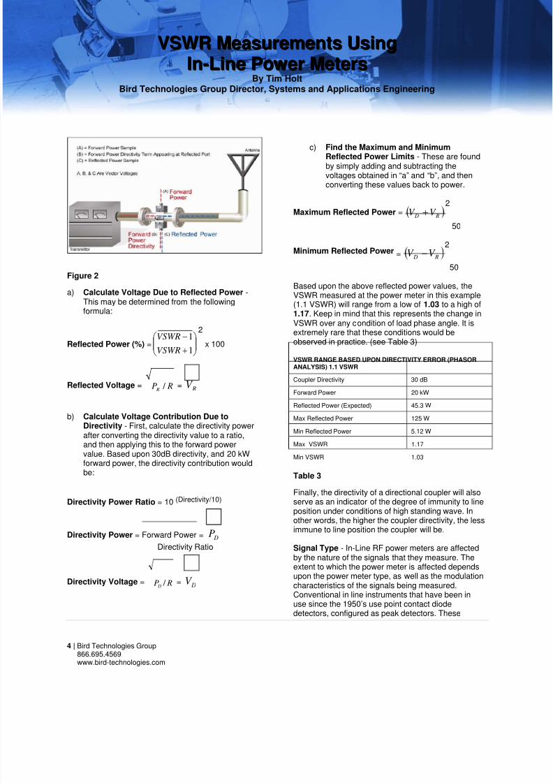
Figure 2
a) Calculate Voltage Due to Reflected Power -This may be determined from the followingformula:
Reflected Power (%) =
+
−
1
1
VSWR
VSWR2
x 100
Reflected Voltage = RP R
/ = RV
b) Calculate Voltage Contribution Due toDirectivity - First, calculate the directivity powerafter converting the directivity value to a ratio,and then applying this to the forward powervalue. Based upon 30dB directivity, and 20 kWforward power, the directivity contribution wouldbe:
Directivity Power Ratio = 10 (Directivity/10)
Directivity Power = Forward Power DP=
Directivity Ratio
Directivity Voltage = RP
D/
= DV
c) Find the Maximum and MinimumReflected Power Limits - These are foundby simply adding and subtracting thevoltages obtained in “a” and “b”, and thenconverting these values back to power.
Maximum Reflected Power = ( ) R D
V V +
2
50
Minimum Reflected Power = ( ) R D
V V −
2
50
Based upon the above reflected power values, theVSWR measured at the power meter in this example(1.1 VSWR) will range from a low of 1.03 to a high of1.17. Keep in mind that this represents the change inVSWR over any condition of load phase angle. It isextremely rare that these conditions would beobserved in practice. (see Table 3)
VSWR RANGE BASED UPON DIRECTIVITY ERROR (PHASORANALYSIS) 1.1 VSWR
Coupler Directivity 30 dB
Forward Power 20 kW
Reflected Power (Expected) 45.3 W
Max Reflected Power 125 W
Min Reflected Power 5.12 W
Max VSWR 1.17
Min VSWR 1.03
Table 3
Finally, the directivity of a directional coupler will alsoserve as an indicator of the degree of immunity to lineposition under conditions of high standing wave. Inother words, the higher the coupler directivity, the lessimmune to line position the coupler will be.
Signal Type - In-Line RF power meters are affectedby the nature of the signals that they measure. Theextent to which the power meter is affected dependsupon the power meter type, as well as the modulationcharacteristics of the signals being measured.Conventional in line instruments that have been inuse since the 1950’s use point contact diodedetectors, configured as peak detectors. These

8/4/2019 VSWR Measurement
http://slidepdf.com/reader/full/vswr-measurement 5/5
VVSSWWRR MMeeaassuurreemmeennttss UUssiinngg IInn--LLiinnee PPoowweerr MMeetteerrss
By Tim HoltBird Technologies Group Director, Systems and Applications Engineering
5 | Bird Technologies Group866.695.4569www.bird-technologies.com
instruments are typically connected to analog meterswith scales calibrated to read average power. Underconditions where modulation is not present (CW), orthe crest factor of the signals to be measured is low,these instruments perform very well. As the crestfactor of the signal is increased, these instrumentstend to follow the envelope of the modulationwaveform, resulting in greater inaccuracy. Latergeneration diode type power meters use detectorsoperated in the diode square law region, where thediode voltage output is proportional to the square ofthe input voltage. These detectors will providedetected voltages proportional to true power, as longas the signal applied to the detector is bounded within
the diode square law region.
In-Line Power Meter Location - The location of thedirectional power meter within the transmissionsystem may have a significant effect upon the abilityof the instrument to resolve antenna VSWR. Theprime consideration related to the location of thepower meter is that the losses associated with thetransmission line, as well as the insertion loss valuesof any other system components will have the effectof isolating (masking) the power meter from themeasurement point. The best way to illustrate thispoint is with an example:
We are operating a 10 kW transmitter, connected toan antenna located 730’ up the tower, using 1-5/8”Heliax transmission line. The VSWR, measured with adirectional power meter located at the output of thetransmitter is 1.08. The question is: what is the VSWRat the antenna?
The loss of 1-5/8” Heliax is specified at 0.2 dB per100’ of length, this means that the one way loss dueto the feedline is 1.46 dB. Since a VSWR or ReturnLoss measurement is comprised of both incident andreflected parameters, the one way loss must bedoubled to arrive at the isolation. A 1.08 VSWRcorresponds to a return loss of 28.3 dB. When thefeedline isolation is subtracted from this value, the
new return loss, at the antenna is 25.3 dB, whichcorresponds to a VSWR of 1.12. (see Table 4)
VSWR MASKING DUE TO TRANSMISSION LINE LOSS
VSWR Measures at Transmitter 1.08
1-5/8 Heliax Loss 0.2 dB / 100’
Total Line Loss 1.46 dB
VSWR at Antenna 1.12
Table 4
If the path between the in-line power meter and theantenna includes components such as switches,adapters, or other items, the insertion losses of thesecomponents will also have the effect of further
isolating the power meter from the antenna.
Conclusion - VSWR measurements using in-linepower meters are important components in the day today operation of broadcast transmission systems.Following the above guidelines will help to insure thatthe highest quality measurements are obtained usingthis approach.


