Vsphere Esxi Vcenter Server 51 Networking Guide
172
7/15/2019 Vsphere Esxi Vcenter Server 51 Networking Guide http://slidepdf.com/reader/full/vsphere-esxi-vcenter-server-51-networking-guide-563280a1ebe2b 1/172 vSphere Networking ESXi 5.1 vCenter Server 5.1 This document supports the version of each product listed and supports all subsequent versions until the document is replaced by a new edition. To check for more recent editions of this document, see http://www.vmware.com/support/pubs . EN-000913-01
-
Upload
oscar-carrillo-miranda -
Category
Documents
-
view
104 -
download
0
Transcript of Vsphere Esxi Vcenter Server 51 Networking Guide
7/15/2019 Vsphere Esxi Vcenter Server 51 Networking Guide
http://slidepdf.com/reader/full/vsphere-esxi-vcenter-server-51-networking-guide-563280a1ebe2b 1/172
vSphere NetworkingESXi 5.1
vCenter Server 5.1
This document supports the version of each product listed and
supports all subsequent versions until the document is replaced
by a new edition. To check for more recent editions of thisdocument, see http://www.vmware.com/support/pubs.
EN-000913-01
7/15/2019 Vsphere Esxi Vcenter Server 51 Networking Guide
http://slidepdf.com/reader/full/vsphere-esxi-vcenter-server-51-networking-guide-563280a1ebe2b 2/172
vSphere Networking
2 VMware, Inc.
You can find the most up-to-date technical documentation on the VMware Web site at:
http://www.vmware.com/support/
The VMware Web site also provides the latest product updates.
If you have comments about this documentation, submit your feedback to:
Copyright © 2009–2012 VMware, Inc. All rights reserved. This product is protected by U.S. and international copyright andintellectual property laws. VMware products are covered by one or more patents listed athttp://www.vmware.com/go/patents.
VMware is a registered trademark or trademark of VMware, Inc. in the United States and/or other jurisdictions. All other marksand names mentioned herein may be trademarks of their respective companies.
VMware, Inc.
3401 Hillview Ave.Palo Alto, CA 94304www.vmware.com
7/15/2019 Vsphere Esxi Vcenter Server 51 Networking Guide
http://slidepdf.com/reader/full/vsphere-esxi-vcenter-server-51-networking-guide-563280a1ebe2b 3/172
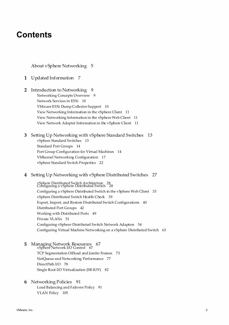
Contents
About vSphere Networking 5
1 Updated Information 7
2 Introduction to Networking 9
Networking Concepts Overview 9
Network Services in ESXi 10
VMware ESXi Dump Collector Support 10
View Networking Information in the vSphere Client 11
View Networking Information in the vSphere Web Client 11
View Network Adapter Information in the vSphere Client 11
3 Setting Up Networking with vSphere Standard Switches 13
vSphere Standard Switches 13
Standard Port Groups 14
Port Group Configuration for Virtual Machines 14
VMkernel Networking Configuration 17
vSphere Standard Switch Properties 22
4 Setting Up Networking with vSphere Distributed Switches 27
vSphere Distributed Switch Architecture 28Configuring a vSphere Distributed Switch 28
Configuring a vSphere Distributed Switch in the vSphere Web Client 33
vSphere Distributed Switch Health Check 39
Export, Import, and Restore Distributed Switch Configurations 40
Distributed Port Groups 42
Working with Distributed Ports 49
Private VLANs 51
Configuring vSphere Distributed Switch Network Adapters 54
Configuring Virtual Machine Networking on a vSphere Distributed Switch 63
5 Managing Network Resources 67
vSphere Network I/O Control 67
TCP Segmentation Offload and Jumbo Frames 73
NetQueue and Networking Performance 77
DirectPath I/O 78
Single Root I/O Virtualization (SR-IOV) 82
6 Networking Policies 91
Load Balancing and Failover Policy 91
VLAN Policy 105
VMware, Inc. 3
7/15/2019 Vsphere Esxi Vcenter Server 51 Networking Guide
http://slidepdf.com/reader/full/vsphere-esxi-vcenter-server-51-networking-guide-563280a1ebe2b 4/172
Security Policy 108
Traffic Shaping Policy 114
Resource Allocation Policy 121
Monitoring Policy 123
Port Blocking Policies 125
Manage Policies for Multiple Port Groups on a vSphere Distributed Switch 126
Manage Policies for Multiple Port Groups on a vSphere Distributed Switch in the
vSphere Web Client 129
7 Advanced Networking 133
Internet Protocol Version 6 (IPv6) Support 133
VLAN Configuration 134
Working With Port Mirroring 135
Configure NetFlow Settings 145
Configure NetFlow Settings with the vSphere Web Client 146
Switch Discovery Protocol 146
Change the DNS and Routing Configuration 149
Change the DNS and Routing Configuration in the vSphere Web Client 150
MAC Addresses 150
Mounting NFS Volumes 156
Network Rollback and Recovery 157
Stateless Network Deployment 160
8 Networking Best Practices 163
Index 165
vSphere Networking
4 VMware, Inc.
7/15/2019 Vsphere Esxi Vcenter Server 51 Networking Guide
http://slidepdf.com/reader/full/vsphere-esxi-vcenter-server-51-networking-guide-563280a1ebe2b 5/172
About vSphere Networking
vSphere Networking provides information about configuring networking for VMware vSphere® , including how
to create vSphere distributed switches and vSphere standard switches.
vSphere Networking also provides information on monitoring networks, managing network resources, and
networking best practices.
Intended Audience
The information presented is written for experienced Windows or Linux system administrators who are
familiar with network configuration and virtual machine technology.
VMware, Inc. 5

7/15/2019 Vsphere Esxi Vcenter Server 51 Networking Guide
http://slidepdf.com/reader/full/vsphere-esxi-vcenter-server-51-networking-guide-563280a1ebe2b 6/172
vSphere Networking
6 VMware, Inc.
7/15/2019 Vsphere Esxi Vcenter Server 51 Networking Guide
http://slidepdf.com/reader/full/vsphere-esxi-vcenter-server-51-networking-guide-563280a1ebe2b 7/172
Updated Information 1This vSphere Networking documentation is updated with each release of the product or when necessary.
This table provides the update history of vSphere Networking.
Revision Description
EN-000913-01 n The section “Single Root I/O Virtualization (SR-IOV),” on page 82 now contains more clearconfiguration requirements and information about configuring a virtual machine to use a virtualfunction.
n The section “NetQueue and Networking Performance,” on page 77 contains instructions based oncommands for ESXi 5.x.
n “Set or Change Allocation Type,” on page 154 improves the example of a MAC address range.
EN-000913-00 Initial release.
VMware, Inc. 7

7/15/2019 Vsphere Esxi Vcenter Server 51 Networking Guide
http://slidepdf.com/reader/full/vsphere-esxi-vcenter-server-51-networking-guide-563280a1ebe2b 8/172
vSphere Networking
8 VMware, Inc.
7/15/2019 Vsphere Esxi Vcenter Server 51 Networking Guide
http://slidepdf.com/reader/full/vsphere-esxi-vcenter-server-51-networking-guide-563280a1ebe2b 9/172
Introduction to Networking 2The basic concepts of ESXi networking and how to set up and configure a network in a vSphere environment
are discussed.
This chapter includes the following topics:
n“Networking Concepts Overview,” on page 9
n “Network Services in ESXi,” on page 10
n “VMware ESXi Dump Collector Support,” on page 10
n “View Networking Information in the vSphere Client,” on page 11
n “View Networking Information in the vSphere Web Client,” on page 11
n “View Network Adapter Information in the vSphere Client,” on page 11
Networking Concepts Overview
A few concepts are essential for a thorough understanding of virtual networking. If you are new to ESXi, it is
helpful to review these concepts.
A physical network is a network of physical machines that are connected so that they can send data to and
receive data from each other. VMware ESXi runs on a physical machine.
A virtual network is a network of virtual machines running on a single physical machine that are connected
logically to each other so that they can send data to and receive data from each other. Virtual machines can be
connected to the virtual networks that you create when you add a network.
A physical Ethernet switch manages network traffic between machines on the physical network. A switch has
multiple ports, each of which can be connected to a single machine or another switch on the network. Each
port can be configured to behave in certain ways depending on the needs of the machine connected to it. The
switch learns which hosts are connected to which of its ports and uses that information to forward traffic to
the correct physical machines. Switches are the core of a physical network. Multiple switches can be connected
together to form larger networks.
A vSphere standard switch works much like a physical Ethernet switch. It detects which virtual machines are
logically connected to each of its virtual ports and uses that information to forward traffic to the correct virtual
machines. A vSphere standard switch can be connected to physical switches by using physical Ethernet
adapters, also referred to as uplink adapters, to join virtual networks with physical networks. This type of
connection is similar to connecting physical switches together to create a larger network. Even though a
vSphere standard switch works much like a physical switch, it does not have some of the advanced
functionality of a physical switch.
A vSphere distributed switch acts as a single switch across all associated hosts on a datacenter. This allows
virtual machines to maintain consistent network configuration as they migrate across multiple hosts.
VMware, Inc. 9
7/15/2019 Vsphere Esxi Vcenter Server 51 Networking Guide
http://slidepdf.com/reader/full/vsphere-esxi-vcenter-server-51-networking-guide-563280a1ebe2b 10/172
A distributed port is a port on a vSphere distributed switch that connects to a host’s VMkernel or to a virtual
machine’s network adapter.
A port group specifies port configuration options such as bandwidth limitations and VLAN tagging policies
for each member port. Network services connect to standard switches through port groups. Port groups define
how a connection is made through the switch to the network. Typically, a single standard switch is associated
with one or more port groups.
A distributed port group is a port group associated with a vSphere distributed switch and specifies port
configuration options for each member port. Distributed port groups define how a connection is made through
the vSphere distributed switch to the network.
NIC teaming occurs when multiple uplink adapters are associated with a single switch to form a team. A team
can either share the load of traffic between physical and virtual networks among some or all of its members,
or provide passive failover in the event of a hardware failure or a network outage.
VLANs enable a single physical LAN segment to be further segmented so that groups of ports are isolated
from one another as if they were on physically different segments. The standard is 802.1Q.
The VMkernel TCP/IP networking stack supports iSCSI, NFS, vMotion, and Fault Tolerance Logging. Virtual
machines run their own systems’ TCP/IP stacks and connect to the VMkernel at the Ethernet level through
standard and distributed switches.IP storage refers to any form of storage that uses TCP/IP network communication as its foundation. iSCSI can
be used as a virtual machine datastore, and NFS can be used as a virtual machine datastore and for direct
mounting of .ISO files, which are presented as CD-ROMs to virtual machines.
TCP Segmentation Offload, TSO, allows a TCP/IP stack to emit large frames (up to 64KB) even though the
maximum transmission unit (MTU) of the interface is smaller. The network adapter then separates the large
frame into MTU-sized frames and prepends an adjusted copy of the initial TCP/IP headers.
Migration with vMotion enables a virtual machine that is powered on to be transferred from one ESXi host to
another without shutting down the virtual machine. The optional vMotion feature requires its own license key.
Network Services in ESXi
A virtual network provides several services to the host and virtual machines.
You can enable two types of network services in ESXi:
n Connecting virtual machines to the physical network and to each other.
n Connecting VMkernel services (such as NFS, iSCSI, or vMotion) to the physical network.
VMware ESXi Dump Collector Support
The ESXi dump collector sends VMkernel core contents to a network server when the system encounters a
critical failure.
ESXi 5.1 dump collector supports both vSphere standard and distributed switches, as well as Cisco Nexus 1000
series switches. 802.1q tagging is allowed and set to zero (0) by default. The dump collector can also use any
available uplink, if that uplink's port group is connected to a team.
Any changes to the IP address for the dump collector interface is automatically updated if the IP addresses for
a configured physical network adapter changes. Dump collector also adjusts its default gateway if the gateway
configuration changes.
If you try to delete the VMkernel network adapter used by the dump collector, the operation fails and a warning
message appears. To delete the VMkernel network adapter used by the dump collector, disable dump
collections and delete the adapter.
vSphere Networking
10 VMware, Inc.
7/15/2019 Vsphere Esxi Vcenter Server 51 Networking Guide
http://slidepdf.com/reader/full/vsphere-esxi-vcenter-server-51-networking-guide-563280a1ebe2b 11/172
There is no authentication or encryption in the file transfer session from a crashed host to the dump collector.
VMware recommends that you configure dump collector on a separate VLAN when possible to isolate the
ESXi core from regular network traffic.
For information about installing and configuring dump collector, see the vSphere Installation and Setup
documentation.
View Networking Information in the vSphere ClientThe vSphere Client shows general networking information and information specific to network adapters.
Procedure
1 Log in to the vSphere Client and select the host from the inventory panel.
2 Click the Configuration tab and click Networking.
3 (Optional) Choose the type of networking to view.
Option Description
vSphere Standard Switch Displays vSphere standard switch networking on the host.
vSphere Distributed Switch Displays vSphere distributed switch networking on the host.
The vSphere Distributed Switch option appears only on hosts that are connected to one or more vSphere
distributed switches.
Networking information is displayed for each virtual switch on the host.
View Networking Information in the vSphere Web Client
The vSphere Web Client shows general networking information and information specific to network adapters.
Procedure
1 Browse to a host in the vSphere Web Client.
2 Click the Manage tab and select Networking > Virtual switches.
3 Select a switch from the list to view configuration information.
A schematic of the selected switch appears at the bottom of the screen.
View Network Adapter Information in the vSphere Client
For each physical network adapter on the host, you can view information such as the speed, duplex, and
observed IP ranges.
Procedure
1 Log in to the vSphere Client and select the Hosts and Clusters inventory view.
2 Select the host in the inventory pane.
3 Click the Configuration tab, and click Network Adapters.
The network adapters panel shows the following information.
Table 2-1. Network Adapter Parameters
Option Description
Device Name of the network adapter.
Speed Actual speed and duplex of the network adapter.
Chapter 2 Introduction to Networking
VMware, Inc. 11

7/15/2019 Vsphere Esxi Vcenter Server 51 Networking Guide
http://slidepdf.com/reader/full/vsphere-esxi-vcenter-server-51-networking-guide-563280a1ebe2b 12/172
Table 2-1. Network Adapter Parameters (Continued)
Option Description
Configured Configured speed and duplex of the network adapter.
Switch vSphere standard switch or vSphere distributed switch thatthe network adapter is associated with.
Observed IP ranges IP addresses that the network adapter is likely to have accessto.
Wake on LAN supported Network adapter ability to support Wake on the LAN.
vSphere Networking
12 VMware, Inc.
7/15/2019 Vsphere Esxi Vcenter Server 51 Networking Guide
http://slidepdf.com/reader/full/vsphere-esxi-vcenter-server-51-networking-guide-563280a1ebe2b 13/172
Setting Up Networking with vSphereStandard Switches 3
vSphere standard switches handle network traffic at the host level in a vSphere environment.
Use the vSphere Client to add networking based on the categories that reflect the types of network services.
n Virtual machines
n VMkernel
This chapter includes the following topics:
n “vSphere Standard Switches,” on page 13
n “Standard Port Groups,” on page 14
n “Port Group Configuration for Virtual Machines,” on page 14
n “VMkernel Networking Configuration,” on page 17
n “vSphere Standard Switch Properties,” on page 22
vSphere Standard Switches
You can create abstracted network devices called vSphere standard switches. A standard switch can bridge
traffic internally between virtual machines in the same port group and link to external networks.
You can use standard switches to combine the bandwidth of multiple network adapters and balance
communications traffic among them. You can also configure a standard switch to handle physical NIC failover.
A vSphere standard switch models a physical Ethernet switch. The default number of logical ports for a
standard switch is 120. You can connect one network adapter of a virtual machine to each port. Each uplink
adapter associated with a standard switch uses one port. Each logical port on the standard switch is a member
of a single port group. Each standard switch can also have one or more port groups assigned to it. For
information about maximum allowed ports and port groups, see the Configuration Maximums documentation.
When two or more virtual machines are connected to the same standard switch, network traffic between them
is routed locally. If an uplink adapter is attached to the standard switch, each virtual machine can access theexternal network that the adapter is connected to.
VMware, Inc. 13
7/15/2019 Vsphere Esxi Vcenter Server 51 Networking Guide
http://slidepdf.com/reader/full/vsphere-esxi-vcenter-server-51-networking-guide-563280a1ebe2b 14/172
Standard Port Groups
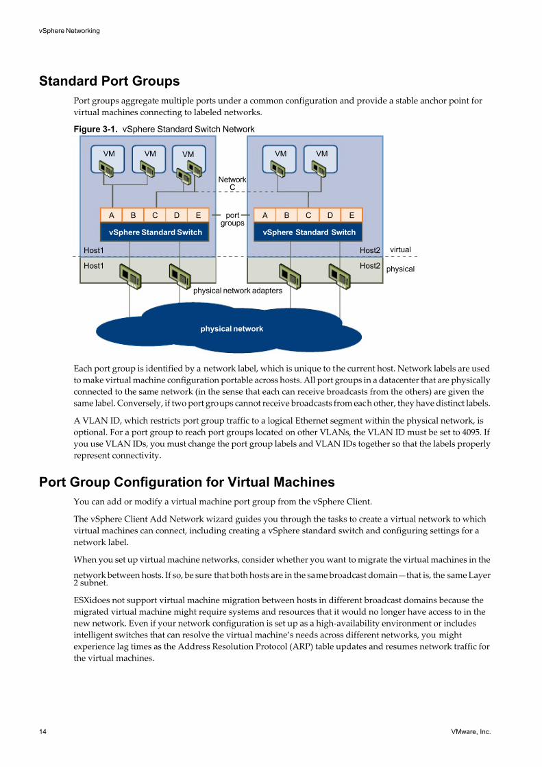
Port groups aggregate multiple ports under a common configuration and provide a stable anchor point for
virtual machines connecting to labeled networks.
Figure 3-1. vSphere Standard Switch Network
physical network adapters
Host1
Host1
Host2
Host2
portgroups
NetworkC
VM VM VM VMVM
vSphere Standard Switch
A B C D E
vSphere Standard Switch
A B C D E
virtual
physical
physical network
Each port group is identified by a network label, which is unique to the current host. Network labels are used
to make virtual machine configuration portable across hosts. All port groups in a datacenter that are physically
connected to the same network (in the sense that each can receive broadcasts from the others) are given the
same label. Conversely, if two port groups cannot receive broadcasts from each other, they have distinct labels.
A VLAN ID, which restricts port group traffic to a logical Ethernet segment within the physical network, is
optional. For a port group to reach port groups located on other VLANs, the VLAN ID must be set to 4095. If
you use VLAN IDs, you must change the port group labels and VLAN IDs together so that the labels properly
represent connectivity.
Port Group Configuration for Virtual Machines
You can add or modify a virtual machine port group from the vSphere Client.
The vSphere Client Add Network wizard guides you through the tasks to create a virtual network to which
virtual machines can connect, including creating a vSphere standard switch and configuring settings for a
network label.
When you set up virtual machine networks, consider whether you want to migrate the virtual machines in the
network between hosts. If so, be sure that both hosts are in the same broadcast domain—that is, the same Layer2 subnet.
ESXidoes not support virtual machine migration between hosts in different broadcast domains because the
migrated virtual machine might require systems and resources that it would no longer have access to in the
new network. Even if your network configuration is set up as a high-availability environment or includes
intelligent switches that can resolve the virtual machine’s needs across different networks, you might
experience lag times as the Address Resolution Protocol (ARP) table updates and resumes network traffic for
the virtual machines.
vSphere Networking
14 VMware, Inc.
7/15/2019 Vsphere Esxi Vcenter Server 51 Networking Guide
http://slidepdf.com/reader/full/vsphere-esxi-vcenter-server-51-networking-guide-563280a1ebe2b 15/172
Virtual machines reach physical networks through uplink adapters. A vSphere standard switch can transfer
data to external networks only when one or more network adapters are attached to it. When two or more
adapters are attached to a single standard switch, they are transparently teamed.
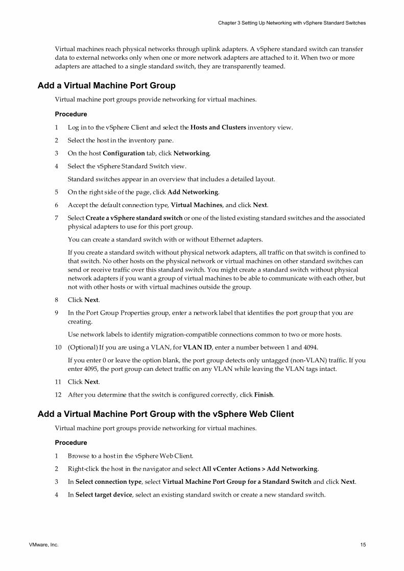
Add a Virtual Machine Port Group
Virtual machine port groups provide networking for virtual machines.
Procedure
1 Log in to the vSphere Client and select the Hosts and Clusters inventory view.
2 Select the host in the inventory pane.
3 On the host Configuration tab, click Networking.
4 Select the vSphere Standard Switch view.
Standard switches appear in an overview that includes a detailed layout.
5 On the right side of the page, click Add Networking.
6 Accept the default connection type, Virtual Machines , and click Next.
7 Select Create a vSphere standard switch or one of the listed existing standard switches and the associated
physical adapters to use for this port group.
You can create a standard switch with or without Ethernet adapters.
If you create a standard switch without physical network adapters, all traffic on that switch is confined to
that switch. No other hosts on the physical network or virtual machines on other standard switches can
send or receive traffic over this standard switch. You might create a standard switch without physical
network adapters if you want a group of virtual machines to be able to communicate with each other, but
not with other hosts or with virtual machines outside the group.
8 Click Next.
9 In the Port Group Properties group, enter a network label that identifies the port group that you are
creating.
Use network labels to identify migration-compatible connections common to two or more hosts.
10 (Optional) If you are using a VLAN, for VLAN ID , enter a number between 1 and 4094.
If you enter 0 or leave the option blank, the port group detects only untagged (non-VLAN) traffic. If you
enter 4095, the port group can detect traffic on any VLAN while leaving the VLAN tags intact.
11 Click Next.
12 After you determine that the switch is configured correctly, click Finish.
Add a Virtual Machine Port Group with the vSphere Web Client
Virtual machine port groups provide networking for virtual machines.
Procedure
1 Browse to a host in the vSphere Web Client.
2 Right-click the host in the navigator and select All vCenter Actions > Add Networking.
3 In Select connection type , select Virtual Machine Port Group for a Standard Switch and click Next.
4 In Select target device , select an existing standard switch or create a new standard switch.
Chapter 3 Setting Up Networking with vSphere Standard Switches
VMware, Inc. 15
7/15/2019 Vsphere Esxi Vcenter Server 51 Networking Guide
http://slidepdf.com/reader/full/vsphere-esxi-vcenter-server-51-networking-guide-563280a1ebe2b 16/172
5 (Optional) If you select an existing standard switch:
a Click Browse.
b Select a standard switch from the list and click OK.
c Click Next and go to Step 8.
6 (Optional) If you create a new standard switch:
a Set the Number of ports using the drop-down menu.
b Click Next and go to the next step.
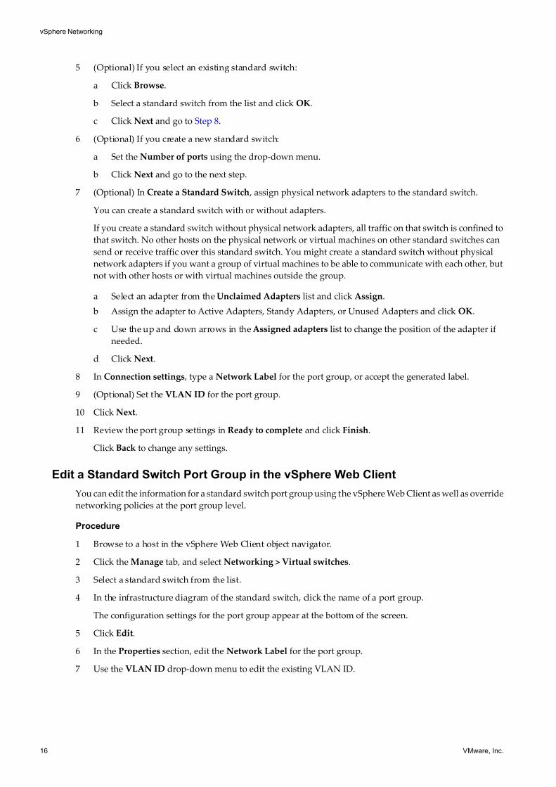
7 (Optional) In Create a Standard Switch , assign physical network adapters to the standard switch.
You can create a standard switch with or without adapters.
If you create a standard switch without physical network adapters, all traffic on that switch is confined to
that switch. No other hosts on the physical network or virtual machines on other standard switches can
send or receive traffic over this standard switch. You might create a standard switch without physical
network adapters if you want a group of virtual machines to be able to communicate with each other, but
not with other hosts or with virtual machines outside the group.
a Select an adapter from the Unclaimed Adapters list and click Assign.
b Assign the adapter to Active Adapters, Standy Adapters, or Unused Adapters and click OK.
c Use the up and down arrows in the Assigned adapters list to change the position of the adapter if
needed.
d Click Next.
8 In Connection settings , type a Network Label for the port group, or accept the generated label.
9 (Optional) Set the VLAN ID for the port group.
10 Click Next.
11 Review the port group settings in Ready to complete and click Finish.
Click Back to change any settings.
Edit a Standard Switch Port Group in the vSphere Web Client
You can edit the information for a standard switch port group using the vSphere Web Client as well as override
networking policies at the port group level.
Procedure
1 Browse to a host in the vSphere Web Client object navigator.
2 Click the Manage tab, and select Networking > Virtual switches.
3 Select a standard switch from the list.
4 In the infrastructure diagram of the standard switch, click the name of a port group.
The configuration settings for the port group appear at the bottom of the screen.
5 Click Edit.
6 In the Properties section, edit the Network Label for the port group.
7 Use the VLAN ID drop-down menu to edit the existing VLAN ID.
vSphere Networking
16 VMware, Inc.
7/15/2019 Vsphere Esxi Vcenter Server 51 Networking Guide
http://slidepdf.com/reader/full/vsphere-esxi-vcenter-server-51-networking-guide-563280a1ebe2b 17/172
8 (Optional) In the Security section:
a Select the check box next to the policy to override the current security policies.
b From the drop-down menu, select Accept or Reject.
9 (Optional) In the Traffic Shaping section:
a Select the check box next to Override to override the current traffic shaping policy.
b In the drop-down menu, Enabled or Disabled traffic shaping policy. If you enable traffic shaping,
enter values for each bandwidth type and bust size.
10 (Optional) In the Teaming and Failover section:
a Select the check box next to the teaming and failover policies to override.
b In the drop-down menus, select the policy setting.
You can also override the adapters used by the port group.
11 Click OK.
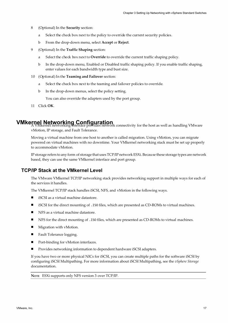
VMkernel Networking ConfigurationA VMkernel networking interface provides network connectivity for the host as well as handling VMware
vMotion, IP storage, and Fault Tolerance.
Moving a virtual machine from one host to another is called migration. Using vMotion, you can migrate
powered on virtual machines with no downtime. Your VMkernel networking stack must be set up properly
to accommodate vMotion.
IP storage refers to any form of storage that uses TCP/IP network ESXi. Because these storage types are network
based, they can use the same VMkernel interface and port group.
TCP/IP Stack at the VMkernel Level
The VMware VMkernel TCP/IP networking stack provides networking support in multiple ways for each of
the services it handles.
The VMkernel TCP/IP stack handles iSCSI, NFS, and vMotion in the following ways.
n iSCSI as a virtual machine datastore.
n iSCSI for the direct mounting of .ISO files, which are presented as CD-ROMs to virtual machines.
n NFS as a virtual machine datastore.
n NFS for the direct mounting of .ISO files, which are presented as CD-ROMs to virtual machines.
n Migration with vMotion.
n Fault Tolerance logging.
n Port-binding for vMotion interfaces.
n Provides networking information to dependent hardware iSCSI adapters.
If you have two or more physical NICs for iSCSI, you can create multiple paths for the software iSCSI by
configuring iSCSI Multipathing. For more information about iSCSI Multipathing, see the vSphere Storage
documentation.
NOTE ESXi supports only NFS version 3 over TCP/IP.
Chapter 3 Setting Up Networking with vSphere Standard Switches
VMware, Inc. 17
7/15/2019 Vsphere Esxi Vcenter Server 51 Networking Guide
http://slidepdf.com/reader/full/vsphere-esxi-vcenter-server-51-networking-guide-563280a1ebe2b 18/172
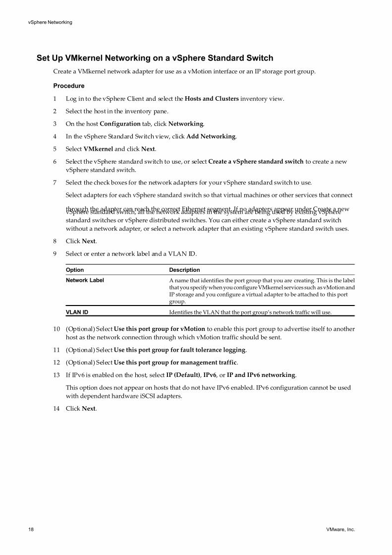
Set Up VMkernel Networking on a vSphere Standard Switch
Create a VMkernel network adapter for use as a vMotion interface or an IP storage port group.
Procedure
1 Log in to the vSphere Client and select the Hosts and Clusters inventory view.
2 Select the host in the inventory pane.
3 On the host Configuration tab, click Networking.
4 In the vSphere Standard Switch view, click Add Networking.
5 Select VMkernel and click Next.
6 Select the vSphere standard switch to use, or select Create a vSphere standard switch to create a new
vSphere standard switch.
7 Select the check boxes for the network adapters for your vSphere standard switch to use.
Select adapters for each vSphere standard switch so that virtual machines or other services that connect
through the adapter can reach the correct Ethernet segment. If no adapters appear under Create a newvSphere standard switch, all the network adapters in the system are being used by existing vSphere
standard switches or vSphere distributed switches. You can either create a vSphere standard switch
without a network adapter, or select a network adapter that an existing vSphere standard switch uses.
8 Click Next.
9 Select or enter a network label and a VLAN ID.
Option Description
Network Label A name that identifies the port group that you are creating. This is the labelthat you specify when you configure VMkernel services such as vMotion andIP storage and you configure a virtual adapter to be attached to this portgroup.
VLAN ID Identifies the VLAN that the port group’s network traffic will use.
10 (Optional) Select Use this port group for vMotion to enable this port group to advertise itself to another
host as the network connection through which vMotion traffic should be sent.
11 (Optional) Select Use this port group for fault tolerance logging.
12 (Optional) Select Use this port group for management traffic.
13 If IPv6 is enabled on the host, select IP (Default) , IPv6 , or IP and IPv6 networking.
This option does not appear on hosts that do not have IPv6 enabled. IPv6 configuration cannot be used
with dependent hardware iSCSI adapters.
14 Click Next.
vSphere Networking
18 VMware, Inc.
7/15/2019 Vsphere Esxi Vcenter Server 51 Networking Guide
http://slidepdf.com/reader/full/vsphere-esxi-vcenter-server-51-networking-guide-563280a1ebe2b 19/172
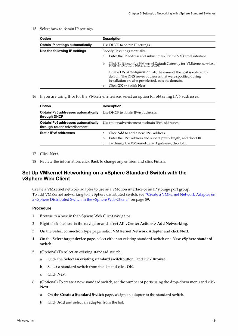
15 Select how to obtain IP settings.
Option Description
Obtain IP settings automatically Use DHCP to obtain IP settings.
Use the following IP settings Specify IP settings manually.
a Enter the IP address and subnet mask for the VMkernel interface.
b Click Edit to set the VMkernel Default Gateway for VMkernel services,such as vMotion, NAS, and iSCSI.
On the DNS Configuration tab, the name of the host is entered bydefault. The DNS server addresses that were specified duringinstallation are also preselected, as is the domain.
c Click OK and click Next.
16 If you are using IPv6 for the VMkernel interface, select an option for obtaining IPv6 addresses.
Option Description
Obtain IPv6 addresses automatically
through DHCP
Use DHCP to obtain IPv6 addresses.
Obtain IPv6 addresses automatically
through router advertisement
Use router advertisement to obtain IPv6 addresses.
Static IPv6 addresses a Click Add to add a new IPv6 address.
b Enter the IPv6 address and subnet prefix length, and click OK.
c To change the VMkernel default gateway, click Edit.
17 Click Next.
18 Review the information, click Back to change any entries, and click Finish.
Set Up VMkernel Networking on a vSphere Standard Switch with thevSphere Web Client
Create a VMkernel network adapter to use as a vMotion interface or an IP storage port group.
To add VMKernel networking to a vSphere distributed switch, see “Create a VMkernel Network Adapter on
a vSphere Distributed Switch in the vSphere Web Client,” on page 59.
Procedure
1 Browse to a host in the vSphere Web Client navigator.
2 Right-click the host in the navigator and select All vCenter Actions > Add Networking.
3 On the Select connection type page, select VMKernel Network Adapter and click Next.
4 On the Select target device page, select either an existing standard switch or a New vSphere standard
switch.
5 (Optional) To select an existing standard switch:
a Click the Select an existing standard switch button , and click Browse.
b Select a standard switch from the list and click OK.
c Click Next.
6 (Optional) To create a new standard switch, set the number of ports using the drop-down menu and click
Next.
a On the Create a Standard Switch page, assign an adapter to the standard switch.
b Click Add and select an adapter from the list.
Chapter 3 Setting Up Networking with vSphere Standard Switches
VMware, Inc. 19
7/15/2019 Vsphere Esxi Vcenter Server 51 Networking Guide
http://slidepdf.com/reader/full/vsphere-esxi-vcenter-server-51-networking-guide-563280a1ebe2b 20/172
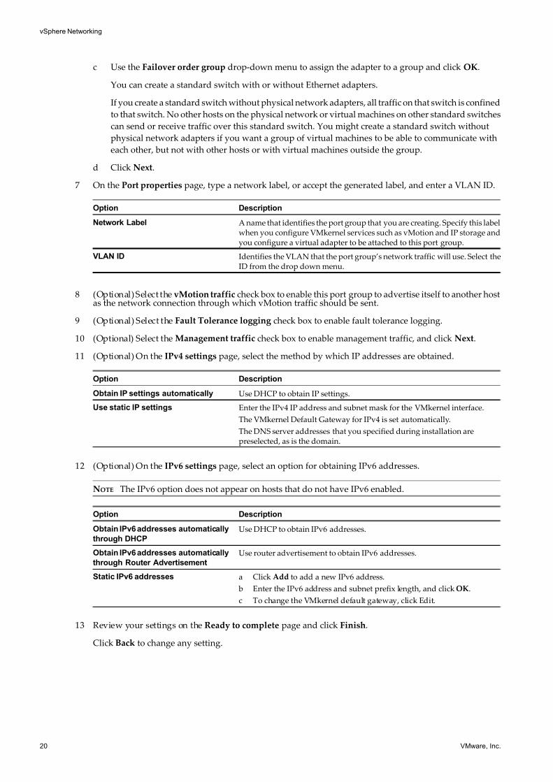
c Use the Failover order group drop-down menu to assign the adapter to a group and click OK.
You can create a standard switch with or without Ethernet adapters.
If you create a standard switch without physical network adapters, all traffic on that switch is confined
to that switch. No other hosts on the physical network or virtual machines on other standard switches
can send or receive traffic over this standard switch. You might create a standard switch without
physical network adapters if you want a group of virtual machines to be able to communicate with
each other, but not with other hosts or with virtual machines outside the group.
d Click Next.
7 On the Port properties page, type a network label, or accept the generated label, and enter a VLAN ID.
Option Description
Network Label A name that identifies the port group that you are creating. Specify this labelwhen you configure VMkernel services such as vMotion and IP storage andyou configure a virtual adapter to be attached to this port group.
VLAN ID Identifies the VLAN that the port group’s network traffic will use. Select theID from the drop down menu.
8 (Optional) Select the vMotion traffic check box to enable this port group to advertise itself to another hostas the network connection through which vMotion traffic should be sent.
9 (Optional) Select the Fault Tolerance logging check box to enable fault tolerance logging.
10 (Optional) Select the Management traffic check box to enable management traffic, and click Next.
11 (Optional) On the IPv4 settings page, select the method by which IP addresses are obtained.
Option Description
Obtain IP settings automatically Use DHCP to obtain IP settings.
Use static IP settings Enter the IPv4 IP address and subnet mask for the VMkernel interface.
The VMkernel Default Gateway for IPv4 is set automatically.
The DNS server addresses that you specified during installation arepreselected, as is the domain.
12 (Optional) On the IPv6 settings page, select an option for obtaining IPv6 addresses.
NOTE The IPv6 option does not appear on hosts that do not have IPv6 enabled.
Option Description
Obtain IPv6 addresses automatically
through DHCP
Use DHCP to obtain IPv6 addresses.
Obtain IPv6 addresses automatically
through Router Advertisement
Use router advertisement to obtain IPv6 addresses.
Static IPv6 addresses a Click Add to add a new IPv6 address.
b Enter the IPv6 address and subnet prefix length, and click OK.
c To change the VMkernel default gateway, click Edit.
13 Review your settings on the Ready to complete page and click Finish.
Click Back to change any setting.
vSphere Networking
20 VMware, Inc.
7/15/2019 Vsphere Esxi Vcenter Server 51 Networking Guide
http://slidepdf.com/reader/full/vsphere-esxi-vcenter-server-51-networking-guide-563280a1ebe2b 21/172
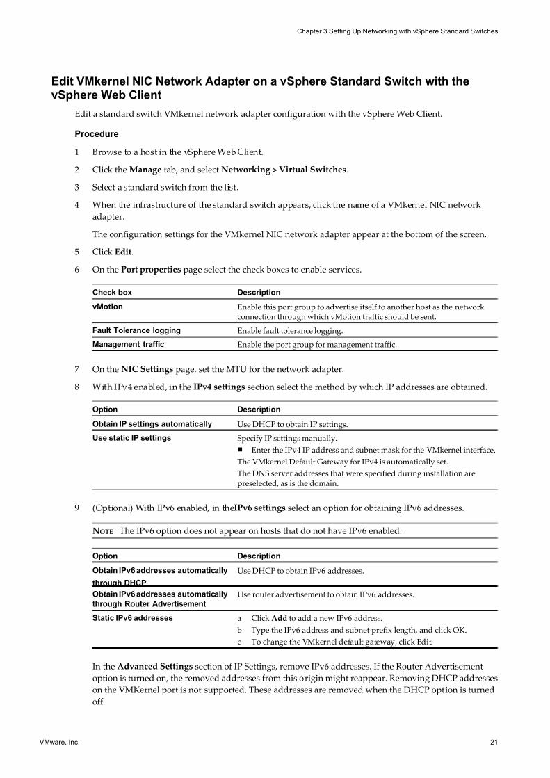
Edit VMkernel NIC Network Adapter on a vSphere Standard Switch with thevSphere Web Client
Edit a standard switch VMkernel network adapter configuration with the vSphere Web Client.
Procedure
1 Browse to a host in the vSphere Web Client.
2 Click the Manage tab, and select Networking > Virtual Switches.
3 Select a standard switch from the list.
4 When the infrastructure of the standard switch appears, click the name of a VMkernel NIC network
adapter.
The configuration settings for the VMkernel NIC network adapter appear at the bottom of the screen.
5 Click Edit.
6 On the Port properties page select the check boxes to enable services.
Check box Description
vMotion Enable this port group to advertise itself to another host as the networkconnection through which vMotion traffic should be sent.
Fault Tolerance logging Enable fault tolerance logging.
Management traffic Enable the port group for management traffic.
7 On the NIC Settings page, set the MTU for the network adapter.
8 With IPv4 enabled, in the IPv4 settings section select the method by which IP addresses are obtained.
Option Description
Obtain IP settings automatically Use DHCP to obtain IP settings.
Use static IP settings Specify IP settings manually.
n Enter the IPv4 IP address and subnet mask for the VMkernel interface.
The VMkernel Default Gateway for IPv4 is automatically set.
The DNS server addresses that were specified during installation arepreselected, as is the domain.
9 (Optional) With IPv6 enabled, in theIPv6 settings select an option for obtaining IPv6 addresses.
NOTE The IPv6 option does not appear on hosts that do not have IPv6 enabled.
Option Description
Obtain IPv6 addresses automatically
through DHCP
Use DHCP to obtain IPv6 addresses.
Obtain IPv6 addresses automatically
through Router Advertisement
Use router advertisement to obtain IPv6 addresses.
Static IPv6 addresses a Click Add to add a new IPv6 address.
b Type the IPv6 address and subnet prefix length, and click OK.
c To change the VMkernel default gateway, click Edit.
In the Advanced Settings section of IP Settings, remove IPv6 addresses. If the Router Advertisement
option is turned on, the removed addresses from this origin might reappear. Removing DHCP addresses
on the VMKernel port is not supported. These addresses are removed when the DHCP option is turned
off.
Chapter 3 Setting Up Networking with vSphere Standard Switches
VMware, Inc. 21
7/15/2019 Vsphere Esxi Vcenter Server 51 Networking Guide
http://slidepdf.com/reader/full/vsphere-esxi-vcenter-server-51-networking-guide-563280a1ebe2b 22/172
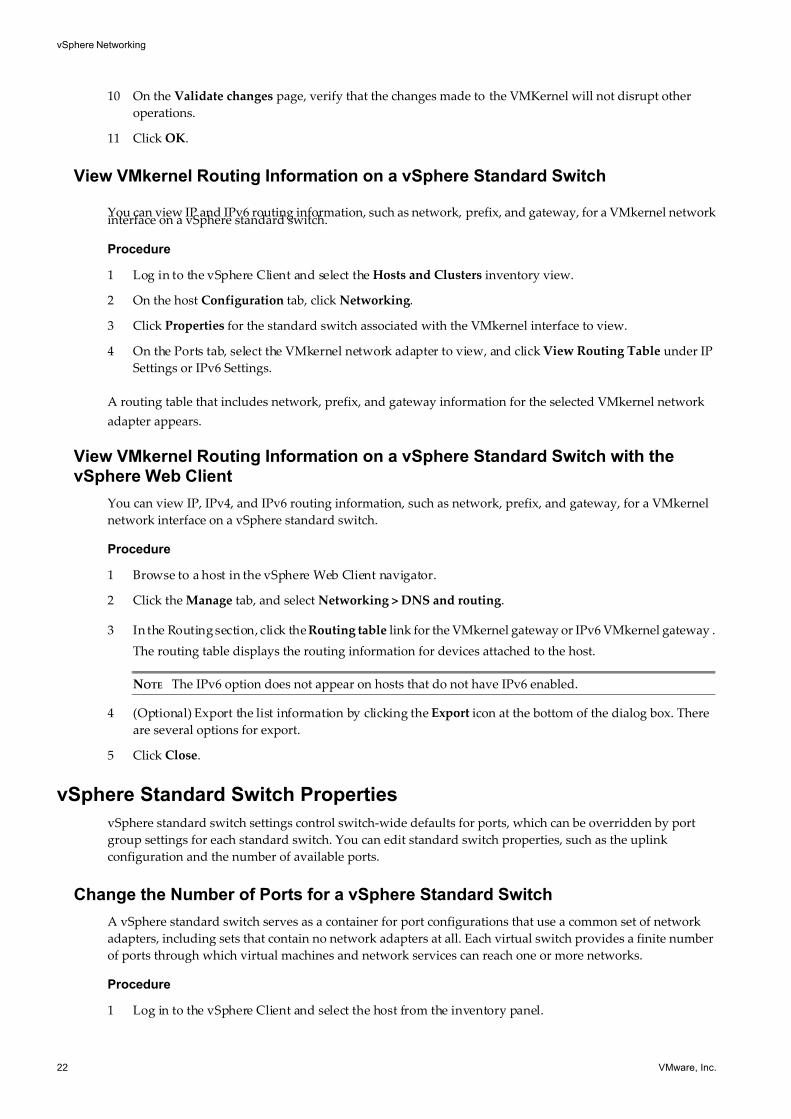
10 On the Validate changes page, verify that the changes made to the VMKernel will not disrupt other
operations.
11 Click OK.
View VMkernel Routing Information on a vSphere Standard Switch
You can view IP and IPv6 routing information, such as network, prefix, and gateway, for a VMkernel networkinterface on a vSphere standard switch.
Procedure
1 Log in to the vSphere Client and select the Hosts and Clusters inventory view.
2 On the host Configuration tab, click Networking.
3 Click Properties for the standard switch associated with the VMkernel interface to view.
4 On the Ports tab, select the VMkernel network adapter to view, and click View Routing Table under IP
Settings or IPv6 Settings.
A routing table that includes network, prefix, and gateway information for the selected VMkernel network
adapter appears.
View VMkernel Routing Information on a vSphere Standard Switch with thevSphere Web Client
You can view IP, IPv4, and IPv6 routing information, such as network, prefix, and gateway, for a VMkernel
network interface on a vSphere standard switch.
Procedure
1 Browse to a host in the vSphere Web Client navigator.
2 Click the Manage tab, and select Networking > DNS and routing.
3 In the Routing section, click the Routing table link for the VMkernel gateway or IPv6 VMkernel gateway .
The routing table displays the routing information for devices attached to the host.
NOTE The IPv6 option does not appear on hosts that do not have IPv6 enabled.
4 (Optional) Export the list information by clicking the Export icon at the bottom of the dialog box. There
are several options for export.
5 Click Close.
vSphere Standard Switch Properties
vSphere standard switch settings control switch-wide defaults for ports, which can be overridden by port
group settings for each standard switch. You can edit standard switch properties, such as the uplink
configuration and the number of available ports.
Change the Number of Ports for a vSphere Standard Switch
A vSphere standard switch serves as a container for port configurations that use a common set of network
adapters, including sets that contain no network adapters at all. Each virtual switch provides a finite number
of ports through which virtual machines and network services can reach one or more networks.
Procedure
1 Log in to the vSphere Client and select the host from the inventory panel.
vSphere Networking
22 VMware, Inc.
7/15/2019 Vsphere Esxi Vcenter Server 51 Networking Guide
http://slidepdf.com/reader/full/vsphere-esxi-vcenter-server-51-networking-guide-563280a1ebe2b 23/172
2 Click the Configuration tab and click Networking.
3 On the right side of the page, click Properties for the standard switch that you want to edit.
4 Click the Ports tab.
5 Select the standard switch item in the Configuration list, and click Edit.
6 Click the General tab.
7 Choose the number of ports that you want to use from the drop-down menu.
8 Click OK.
What to do next
Changes will not take effect until the system is restarted.
Change the Number of Ports for a vSphere Standard Switch in thevSphere Web Client
A vSphere standard switch serves as a container for port configurations that use a common set of network
adapters, including sets that contain no network adapters. Each virtual switch provides a finite number of
ports through which virtual machines and network services can reach one or more networks.
Procedure
1 Browse to a host in the vSphere Web Client.
2 Click the Manage tab, and select Networking > Virtual Switches.
3 Select a standard switch from the list and click Edit settings.
4 Click Edit.
5 In the Properties section, set the Number of ports for the standard switch with the drop-down menu.
6 (Optional) Change the MTU (bytes) for the standard switch.
7 Click OK.
Change the Speed of an Uplink Adapter
You can change the connection speed and duplex of an uplink adapter.
Procedure
1 Log in to the vSphere Client and select the host from the inventory panel.
2 Click the Configuration tab and click Networking.
3 Select a standard switch and click Properties.
4 Click the Network Adapters tab.
5 To change the configured speed and duplex value of a network adapter, select the network adapter and
click Edit.
6 To select the connection speed manually, select the speed and duplex from the drop-down menu.
Choose the connection speed manually if the NIC and a physical switch might fail to negotiate the proper
connection speed. Symptoms of mismatched speed and duplex include low bandwidth or no link
connectivity.
The adapter and the physical switch port it is connected to must be set to the same value, such as auto and
auto or ND and ND, where ND is some speed and duplex, but not auto and ND.
Chapter 3 Setting Up Networking with vSphere Standard Switches
VMware, Inc. 23
7/15/2019 Vsphere Esxi Vcenter Server 51 Networking Guide
http://slidepdf.com/reader/full/vsphere-esxi-vcenter-server-51-networking-guide-563280a1ebe2b 24/172
7 Click OK.
Change the Speed of an Uplink Adapter in the vSphere Web Client
An uplink adapter can become a bottleneck for network traffic if the speed of the uplink adapter is not
compatible with the network traffic speed. You can change the connection speed and duplex of an uplink
adapter to transfer data faster.
Procedure
1 Browse to a host in the vSphere Web Client navigator.
2 Click the Manage tab, and select Networking > Physical adapters.
The physical network adapters associated with the host appear in a table that contains details for each
physical network adapter.
3 To change the configured speed and duplex value of a physical network adapter, select the network
adapter from the list and click Edit.
4 Select the configured speed and duplex of the physical network adapter from the drop-down menu.
5 Click OK.
Add Uplink Adapters
You can associate multiple adapters to a single vSphere standard switch to provide NIC teaming. The team
can share traffic and provide failover.
Procedure
1 Log in to the vSphere Client and select the host from the inventory panel.
2 Click the Configuration tab and click Networking.
3 Select a standard switch and click Properties.
4 Click the Network Adapters tab.
5 Click Add to launch the Add Adapter wizard.
6 Select one or more adapters from the list and click Next.
7 (Optional) To reorder the NICs into a different category, select a NIC and click Move Up and Move
Down.
Option Description
Active Adapters Adapters that the standard switch uses.
Standby Adapters Adapters that become active if one or more of the active adapters fails.
8 Click Next.
9 Review the information on the Adapter Summary page, click Back to change any entries, and click
Finish.
The list of network adapters reappears, showing the adapters that the standard switch now claims.
10 Click Close to exit the dialog box.
The Networking section in the Configuration tab shows the network adapters in their designated order
and categories.
vSphere Networking
24 VMware, Inc.
7/15/2019 Vsphere Esxi Vcenter Server 51 Networking Guide
http://slidepdf.com/reader/full/vsphere-esxi-vcenter-server-51-networking-guide-563280a1ebe2b 25/172
Add Uplink Adapters in the vSphere Web Client
NIC teaming combines multiple nework connections to increase throughput and provide redundancy should
a link fail. You can associate multiple adapters to a single vSphere standard switch to provide NIC teaming.
The NIC team shares network traffic and provides failover.
Procedure
1 Browse to a host in the vSphere Web Client navigator.
2 Click the Manage tab, and select Networking > Virtual Switches.
3 Select the standard switch you want to add an uplink to from the list.
4 Click Manage the physical network adapters.
5 Click Add adapters.
6 Select a network adapter from the list and select the Fail order group to assign it to from the drop-down
menu.
7 Click OK.
8 (Optional) The selected adapter appears in the failover group list under the Assigned Adapters.
Use the up and down arrows to change the position of an adapter in the failover groups.
9 Click OK.
Chapter 3 Setting Up Networking with vSphere Standard Switches
VMware, Inc. 25

7/15/2019 Vsphere Esxi Vcenter Server 51 Networking Guide
http://slidepdf.com/reader/full/vsphere-esxi-vcenter-server-51-networking-guide-563280a1ebe2b 26/172
vSphere Networking
26 VMware, Inc.
7/15/2019 Vsphere Esxi Vcenter Server 51 Networking Guide
http://slidepdf.com/reader/full/vsphere-esxi-vcenter-server-51-networking-guide-563280a1ebe2b 27/172
Setting Up Networking with vSphereDistributed Switches 4
With vSphere distributed switches you can set up and configure networking in a vSphere environment.
This chapter includes the following topics:
n “vSphere Distributed Switch Architecture,” on page 28
n “Configuring a vSphere Distributed Switch,” on page 28
n “Configuring a vSphere Distributed Switch in the vSphere Web Client,” on page 33
n “vSphere Distributed Switch Health Check,” on page 39
n “Export, Import, and Restore Distributed Switch Configurations,” on page 40
n “Distributed Port Groups,” on page 42
n “Working with Distributed Ports,” on page 49
n “Private VLANs,” on page 51
n “Configuring vSphere Distributed Switch Network Adapters,” on page 54
n “Configuring Virtual Machine Networking on a vSphere Distributed Switch,” on page 63
VMware, Inc. 27
7/15/2019 Vsphere Esxi Vcenter Server 51 Networking Guide
http://slidepdf.com/reader/full/vsphere-esxi-vcenter-server-51-networking-guide-563280a1ebe2b 28/172
vSphere Distributed Switch Architecture
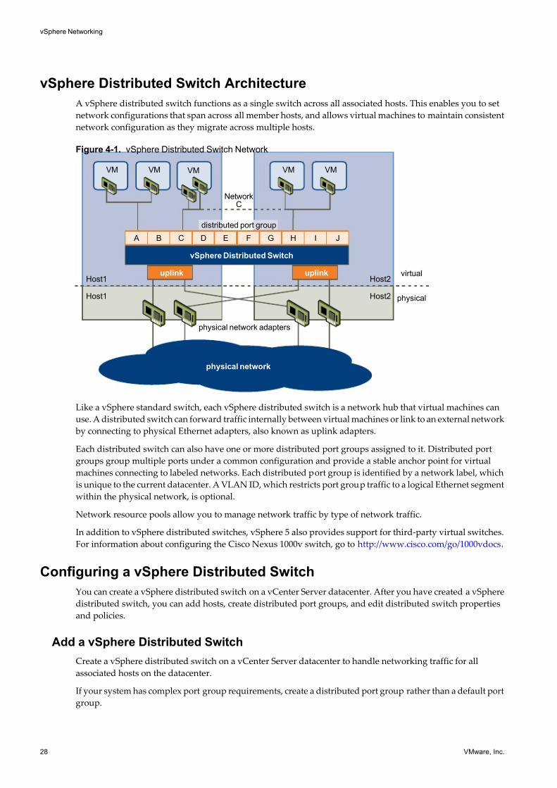
A vSphere distributed switch functions as a single switch across all associated hosts. This enables you to set
network configurations that span across all member hosts, and allows virtual machines to maintain consistent
network configuration as they migrate across multiple hosts.
Figure 4-1. vSphere Distributed Switch Network
physical network adapters
Host1
Host1
Host2
Host2
NetworkC
VM VM VM VMVM
vSphere Distributed Switch
uplink uplink
A B C D E F G H I J
virtual
distributed port group
physical
physical network
Like a vSphere standard switch, each vSphere distributed switch is a network hub that virtual machines can
use. A distributed switch can forward traffic internally between virtual machines or link to an external network
by connecting to physical Ethernet adapters, also known as uplink adapters.
Each distributed switch can also have one or more distributed port groups assigned to it. Distributed port
groups group multiple ports under a common configuration and provide a stable anchor point for virtual
machines connecting to labeled networks. Each distributed port group is identified by a network label, which
is unique to the current datacenter. A VLAN ID, which restricts port group traffic to a logical Ethernet segment
within the physical network, is optional.
Network resource pools allow you to manage network traffic by type of network traffic.
In addition to vSphere distributed switches, vSphere 5 also provides support for third-party virtual switches.
For information about configuring the Cisco Nexus 1000v switch, go to http://www.cisco.com/go/1000vdocs.
Configuring a vSphere Distributed Switch
You can create a vSphere distributed switch on a vCenter Server datacenter. After you have created a vSphere
distributed switch, you can add hosts, create distributed port groups, and edit distributed switch properties
and policies.
Add a vSphere Distributed Switch
Create a vSphere distributed switch on a vCenter Server datacenter to handle networking traffic for all
associated hosts on the datacenter.
If your system has complex port group requirements, create a distributed port group rather than a default port
group.
vSphere Networking
28 VMware, Inc.
7/15/2019 Vsphere Esxi Vcenter Server 51 Networking Guide
http://slidepdf.com/reader/full/vsphere-esxi-vcenter-server-51-networking-guide-563280a1ebe2b 29/172
Procedure
1 In the vSphere Client, select the Networking inventory view and select the datacenter.
2 Select Inventory > Datacenter > New vSphere Distributed Switch.
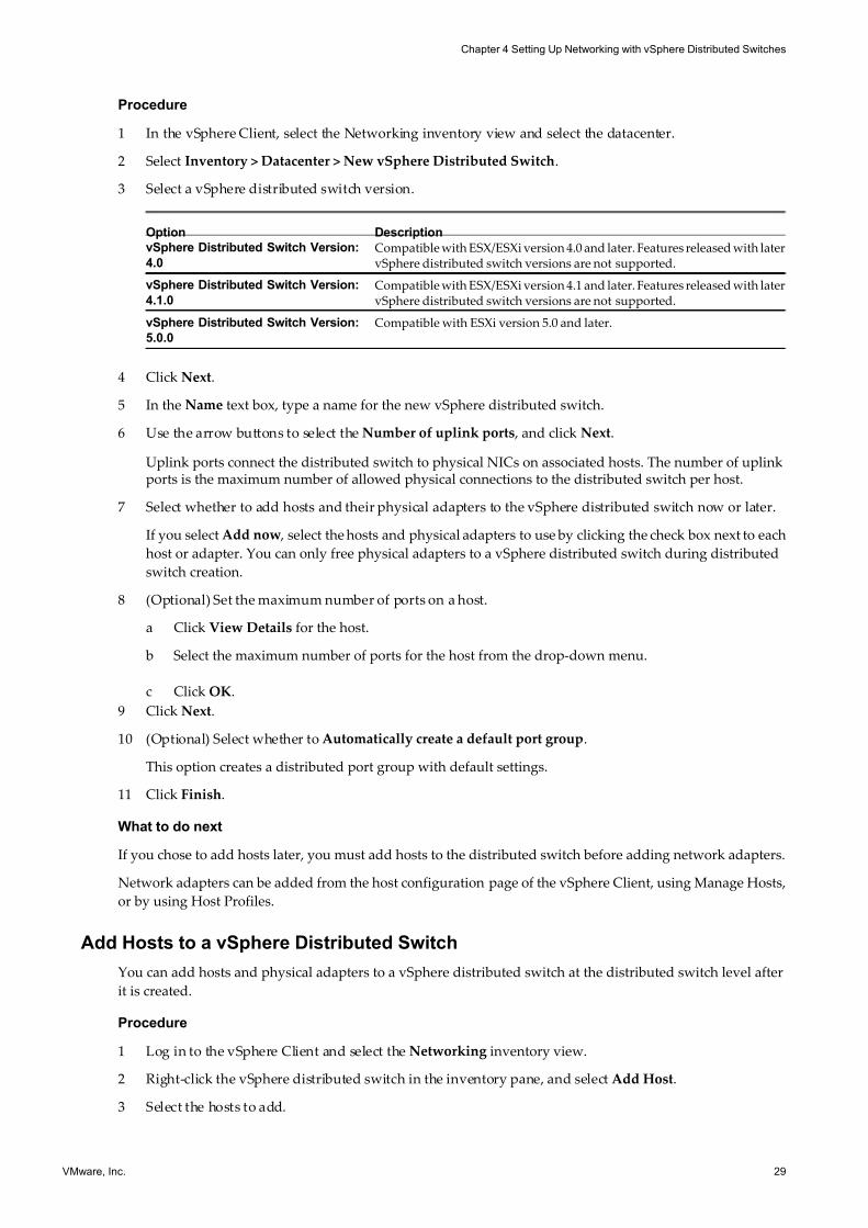
3 Select a vSphere distributed switch version.
Option Description
vSphere Distributed Switch Version:
4.0
Compatible with ESX/ESXi version 4.0 and later. Features released with latervSphere distributed switch versions are not supported.
vSphere Distributed Switch Version:
4.1.0
Compatible with ESX/ESXi version 4.1 and later. Features released with latervSphere distributed switch versions are not supported.
vSphere Distributed Switch Version:
5.0.0
Compatible with ESXi version 5.0 and later.
4 Click Next.
5 In the Name text box, type a name for the new vSphere distributed switch.
6 Use the arrow buttons to select the Number of uplink ports , and click Next.
Uplink ports connect the distributed switch to physical NICs on associated hosts. The number of uplinkports is the maximum number of allowed physical connections to the distributed switch per host.
7 Select whether to add hosts and their physical adapters to the vSphere distributed switch now or later.
If you select Add now , select the hosts and physical adapters to use by clicking the check box next to each
host or adapter. You can only free physical adapters to a vSphere distributed switch during distributed
switch creation.
8 (Optional) Set the maximum number of ports on a host.
a Click View Details for the host.
b Select the maximum number of ports for the host from the drop-down menu.
c Click OK.
9 Click Next.
10 (Optional) Select whether to Automatically create a default port group.
This option creates a distributed port group with default settings.
11 Click Finish.
What to do next
If you chose to add hosts later, you must add hosts to the distributed switch before adding network adapters.
Network adapters can be added from the host configuration page of the vSphere Client, using Manage Hosts,
or by using Host Profiles.
Add Hosts to a vSphere Distributed Switch
You can add hosts and physical adapters to a vSphere distributed switch at the distributed switch level after
it is created.
Procedure
1 Log in to the vSphere Client and select the Networking inventory view.
2 Right-click the vSphere distributed switch in the inventory pane, and select Add Host.
3 Select the hosts to add.
Chapter 4 Setting Up Networking with vSphere Distributed Switches
VMware, Inc. 29
7/15/2019 Vsphere Esxi Vcenter Server 51 Networking Guide
http://slidepdf.com/reader/full/vsphere-esxi-vcenter-server-51-networking-guide-563280a1ebe2b 30/172
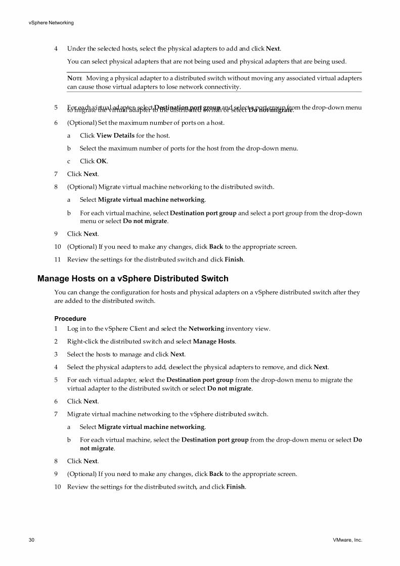
4 Under the selected hosts, select the physical adapters to add and click Next.
You can select physical adapters that are not being used and physical adapters that are being used.
NOTE Moving a physical adapter to a distributed switch without moving any associated virtual adapters
can cause those virtual adapters to lose network connectivity.
5 For each virtual adapter, select Destination port group and select a port group from the drop-down menuto migrate the virtual adapter to the distributed switch or select Do not migrate.
6 (Optional) Set the maximum number of ports on a host.
a Click View Details for the host.
b Select the maximum number of ports for the host from the drop-down menu.
c Click OK.
7 Click Next.
8 (Optional) Migrate virtual machine networking to the distributed switch.
a Select Migrate virtual machine networking.
b For each virtual machine, select Destination port group and select a port group from the drop-downmenu or select Do not migrate.
9 Click Next.
10 (Optional) If you need to make any changes, click Back to the appropriate screen.
11 Review the settings for the distributed switch and click Finish.
Manage Hosts on a vSphere Distributed Switch
You can change the configuration for hosts and physical adapters on a vSphere distributed switch after they
are added to the distributed switch.
Procedure
1 Log in to the vSphere Client and select the Networking inventory view.
2 Right-click the distributed switch and select Manage Hosts.
3 Select the hosts to manage and click Next.
4 Select the physical adapters to add, deselect the physical adapters to remove, and click Next.
5 For each virtual adapter, select the Destination port group from the drop-down menu to migrate the
virtual adapter to the distributed switch or select Do not migrate.
6 Click Next.
7 Migrate virtual machine networking to the vSphere distributed switch.
a Select Migrate virtual machine networking.
b For each virtual machine, select the Destination port group from the drop-down menu or select Do
not migrate.
8 Click Next.
9 (Optional) If you need to make any changes, click Back to the appropriate screen.
10 Review the settings for the distributed switch, and click Finish.
vSphere Networking
30 VMware, Inc.
7/15/2019 Vsphere Esxi Vcenter Server 51 Networking Guide
http://slidepdf.com/reader/full/vsphere-esxi-vcenter-server-51-networking-guide-563280a1ebe2b 31/172
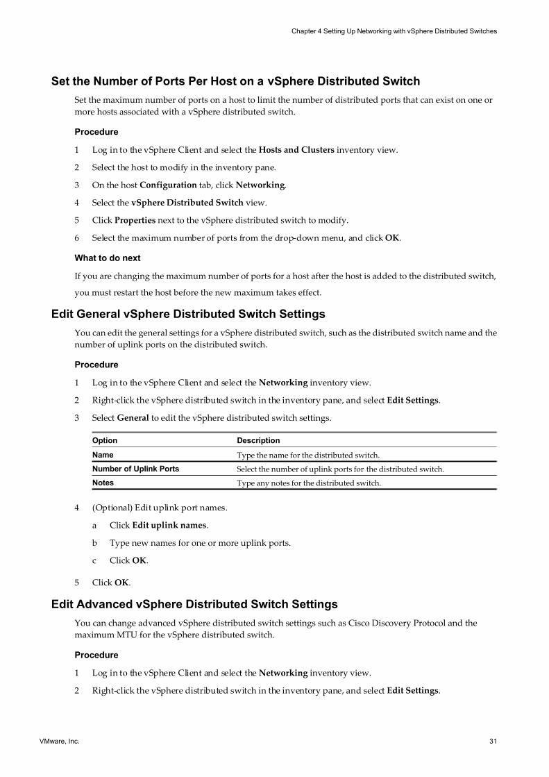
Set the Number of Ports Per Host on a vSphere Distributed Switch
Set the maximum number of ports on a host to limit the number of distributed ports that can exist on one or
more hosts associated with a vSphere distributed switch.
Procedure
1 Log in to the vSphere Client and select the Hosts and Clusters inventory view.
2 Select the host to modify in the inventory pane.
3 On the host Configuration tab, click Networking.
4 Select the vSphere Distributed Switch view.
5 Click Properties next to the vSphere distributed switch to modify.
6 Select the maximum number of ports from the drop-down menu, and click OK.
What to do next
If you are changing the maximum number of ports for a host after the host is added to the distributed switch,
you must restart the host before the new maximum takes effect.
Edit General vSphere Distributed Switch Settings
You can edit the general settings for a vSphere distributed switch, such as the distributed switch name and the
number of uplink ports on the distributed switch.
Procedure
1 Log in to the vSphere Client and select the Networking inventory view.
2 Right-click the vSphere distributed switch in the inventory pane, and select Edit Settings.
3 Select General to edit the vSphere distributed switch settings.
Option Description
Name Type the name for the distributed switch.
Number of Uplink Ports Select the number of uplink ports for the distributed switch.
Notes Type any notes for the distributed switch.
4 (Optional) Edit uplink port names.
a Click Edit uplink names.
b Type new names for one or more uplink ports.
c Click OK.
5 Click OK.
Edit Advanced vSphere Distributed Switch Settings
You can change advanced vSphere distributed switch settings such as Cisco Discovery Protocol and the
maximum MTU for the vSphere distributed switch.
Procedure
1 Log in to the vSphere Client and select the Networking inventory view.
2 Right-click the vSphere distributed switch in the inventory pane, and select Edit Settings.
Chapter 4 Setting Up Networking with vSphere Distributed Switches
VMware, Inc. 31
7/15/2019 Vsphere Esxi Vcenter Server 51 Networking Guide
http://slidepdf.com/reader/full/vsphere-esxi-vcenter-server-51-networking-guide-563280a1ebe2b 32/172
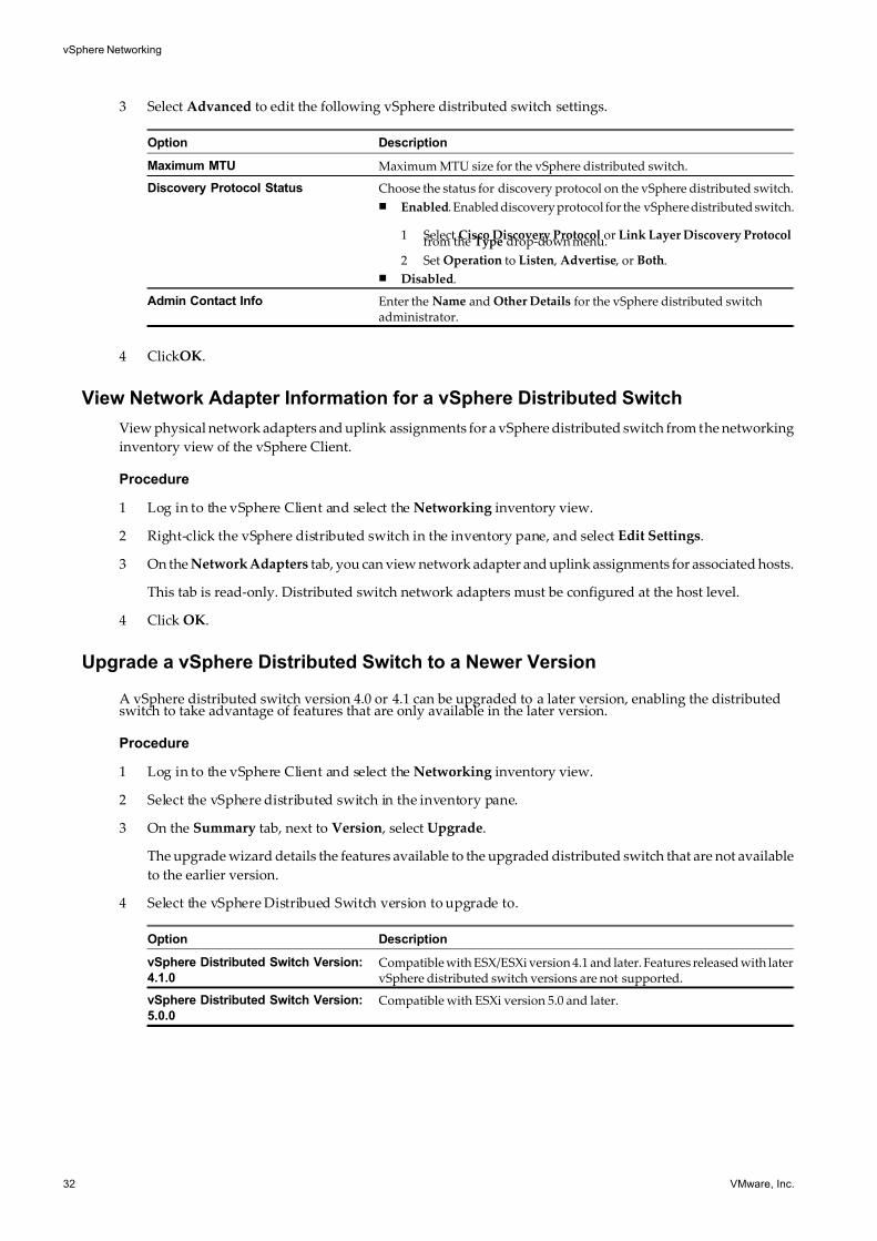
3 Select Advanced to edit the following vSphere distributed switch settings.
Option Description
Maximum MTU Maximum MTU size for the vSphere distributed switch.
Discovery Protocol Status Choose the status for discovery protocol on the vSphere distributed switch.
n Enabled. Enabled discovery protocol for the vSphere distributed switch.
1 Select Cisco Discovery Protocol or Link Layer Discovery Protocolfrom the Type drop-down menu.
2 Set Operation to Listen , Advertise , or Both.
n Disabled.
Admin Contact Info Enter the Name and Other Details for the vSphere distributed switchadministrator.
4 ClickOK.
View Network Adapter Information for a vSphere Distributed Switch
View physical network adapters and uplink assignments for a vSphere distributed switch from the networking
inventory view of the vSphere Client.
Procedure
1 Log in to the vSphere Client and select the Networking inventory view.
2 Right-click the vSphere distributed switch in the inventory pane, and select Edit Settings.
3 On the Network Adapters tab, you can view network adapter and uplink assignments for associated hosts.
This tab is read-only. Distributed switch network adapters must be configured at the host level.
4 Click OK.
Upgrade a vSphere Distributed Switch to a Newer Version
A vSphere distributed switch version 4.0 or 4.1 can be upgraded to a later version, enabling the distributedswitch to take advantage of features that are only available in the later version.
Procedure
1 Log in to the vSphere Client and select the Networking inventory view.
2 Select the vSphere distributed switch in the inventory pane.
3 On the Summary tab, next to Version , select Upgrade.
The upgrade wizard details the features available to the upgraded distributed switch that are not available
to the earlier version.
4 Select the vSphere Distribued Switch version to upgrade to.
Option Description
vSphere Distributed Switch Version:
4.1.0
Compatible with ESX/ESXi version 4.1 and later. Features released with latervSphere distributed switch versions are not supported.
vSphere Distributed Switch Version:
5.0.0
Compatible with ESXi version 5.0 and later.
vSphere Networking
32 VMware, Inc.
7/15/2019 Vsphere Esxi Vcenter Server 51 Networking Guide
http://slidepdf.com/reader/full/vsphere-esxi-vcenter-server-51-networking-guide-563280a1ebe2b 33/172
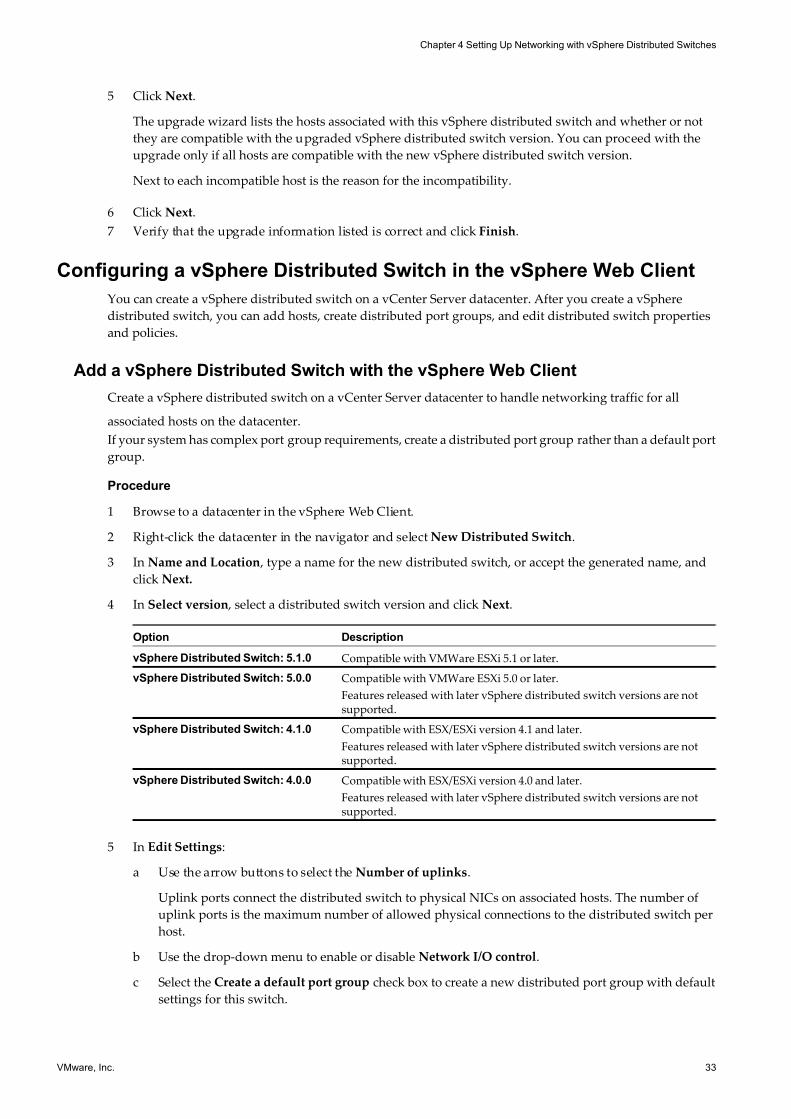
5 Click Next.
The upgrade wizard lists the hosts associated with this vSphere distributed switch and whether or not
they are compatible with the upgraded vSphere distributed switch version. You can proceed with the
upgrade only if all hosts are compatible with the new vSphere distributed switch version.
Next to each incompatible host is the reason for the incompatibility.
6 Click Next.
7 Verify that the upgrade information listed is correct and click Finish.
Configuring a vSphere Distributed Switch in the vSphere Web Client
You can create a vSphere distributed switch on a vCenter Server datacenter. After you create a vSphere
distributed switch, you can add hosts, create distributed port groups, and edit distributed switch properties
and policies.
Add a vSphere Distributed Switch with the vSphere Web Client
Create a vSphere distributed switch on a vCenter Server datacenter to handle networking traffic for all
associated hosts on the datacenter.
If your system has complex port group requirements, create a distributed port group rather than a default port
group.
Procedure
1 Browse to a datacenter in the vSphere Web Client.
2 Right-click the datacenter in the navigator and select New Distributed Switch.
3 In Name and Location , type a name for the new distributed switch, or accept the generated name, and
click Next.
4 In Select version , select a distributed switch version and click Next.
Option Description
vSphere Distributed Switch: 5.1.0 Compatible with VMWare ESXi 5.1 or later.
vSphere Distributed Switch: 5.0.0 Compatible with VMWare ESXi 5.0 or later.
Features released with later vSphere distributed switch versions are notsupported.
vSphere Distributed Switch: 4.1.0 Compatible with ESX/ESXi version 4.1 and later.
Features released with later vSphere distributed switch versions are notsupported.
vSphere Distributed Switch: 4.0.0 Compatible with ESX/ESXi version 4.0 and later.
Features released with later vSphere distributed switch versions are notsupported.
5 In Edit Settings:
a Use the arrow buttons to select the Number of uplinks.
Uplink ports connect the distributed switch to physical NICs on associated hosts. The number of
uplink ports is the maximum number of allowed physical connections to the distributed switch per
host.
b Use the drop-down menu to enable or disable Network I/O control.
c Select the Create a default port group check box to create a new distributed port group with default
settings for this switch.
Chapter 4 Setting Up Networking with vSphere Distributed Switches
VMware, Inc. 33
7/15/2019 Vsphere Esxi Vcenter Server 51 Networking Guide
http://slidepdf.com/reader/full/vsphere-esxi-vcenter-server-51-networking-guide-563280a1ebe2b 34/172
d (Optional) If you opted to create a default port group, use the Port group name field to name the port
group, or accept the generated name.
e Click Next.
6 In Ready to complete , review the settings you selected and click Finish.
Use the Back button to edit any settings.
A distributed switch is created. You can view the features supported on the distributed switch as well as other
details by navigating to the new distributed switch and clicking the Summary tab.
What to do next
Add hosts to the distributed switch before adding network adapters. You can add network adapters from the
Host configuration page of the vSphere Web Client, using Manage Hosts, or by using Host Profiles.
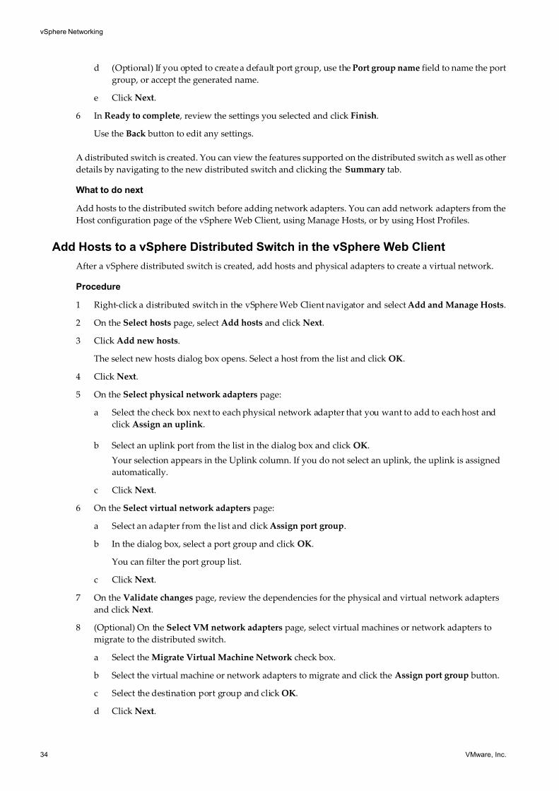
Add Hosts to a vSphere Distributed Switch in the vSphere Web Client
After a vSphere distributed switch is created, add hosts and physical adapters to create a virtual network.
Procedure
1 Right-click a distributed switch in the vSphere Web Client navigator and select Add and Manage Hosts.
2 On the Select hosts page, select Add hosts and click Next.
3 Click Add new hosts.
The select new hosts dialog box opens. Select a host from the list and click OK.
4 Click Next.
5 On the Select physical network adapters page:
a Select the check box next to each physical network adapter that you want to add to each host and
click Assign an uplink.
b Select an uplink port from the list in the dialog box and click OK.
Your selection appears in the Uplink column. If you do not select an uplink, the uplink is assigned
automatically.
c Click Next.
6 On the Select virtual network adapters page:
a Select an adapter from the list and click Assign port group.
b In the dialog box, select a port group and click OK.
You can filter the port group list.
c Click Next.
7 On the Validate changes page, review the dependencies for the physical and virtual network adapters
and click Next.
8 (Optional) On the Select VM network adapters page, select virtual machines or network adapters to
migrate to the distributed switch.
a Select the Migrate Virtual Machine Network check box.
b Select the virtual machine or network adapters to migrate and click the Assign port group button.
c Select the destination port group and click OK.
d Click Next.
vSphere Networking
34 VMware, Inc.
7/15/2019 Vsphere Esxi Vcenter Server 51 Networking Guide
http://slidepdf.com/reader/full/vsphere-esxi-vcenter-server-51-networking-guide-563280a1ebe2b 35/172
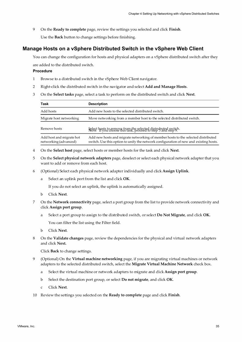
9 On the Ready to complete page, review the settings you selected and click Finish.
Use the Back button to change settings before finishing.
Manage Hosts on a vSphere Distributed Switch in the vSphere Web Client
You can change the configuration for hosts and physical adapters on a vSphere distributed switch after they
are added to the distributed switch.
Procedure
1 Browse to a distributed switch in the vSphere Web Client navigator.
2 Right-click the distributed switch in the navigator and select Add and Manage Hosts.
3 On the Select tasks page, select a task to perform on the distributed switch and click Next.
Task Description
Add hosts Add new hosts to the selected distributed switch.
Migrate host networking Move networking from a member host to the selected distributed switch.
Remove hosts Select hosts to remove from the selected distrubuted switch.NOTE If you choose this task, proceed to step 3 and step 9.
Add host and migrate hotnetworking (advanced)
Add new hosts and migrate networking of member hosts to the selected distributedswitch. Use this option to unify the network configuration of new and existing hosts.
4 On the Select host page, select hosts or member hosts for the task and click Next.
5 On the Select physical network adapters page, deselect or select each physical network adapter that you
want to add or remove from each host.
6 (Optional) Select each physical network adapter individually and click Assign Uplink.
a Select an uplink port from the list and click OK.
If you do not select an uplink, the uplink is automatically assigned.
b Click Next.
7 On the Network connectivity page, select a port group from the list to provide network connectivity and
click Assign port group.
a Select a port group to assign to the distributed switch, or select Do Not Migrate , and click OK.
You can filter the list using the Filter field.
b Click Next.
8 On the Validate changes page, review the dependencies for the physical and virtual network adapters
and click Next.
Click Back to change settings.
9 (Optional) On the Virtual machine networking page, if you are migrating virtual machines or network
adapters to the selected distributed switch, select the Migrate Virtual Machine Network check box.
a Select the virtual machine or network adapters to migrate and click Assign port group.
b Select the destination port group, or select Do not migrate , and click OK.
c Click Next.
10 Review the settings you selected on the Ready to complete page and click Finish.
Chapter 4 Setting Up Networking with vSphere Distributed Switches
VMware, Inc. 35
7/15/2019 Vsphere Esxi Vcenter Server 51 Networking Guide
http://slidepdf.com/reader/full/vsphere-esxi-vcenter-server-51-networking-guide-563280a1ebe2b 36/172
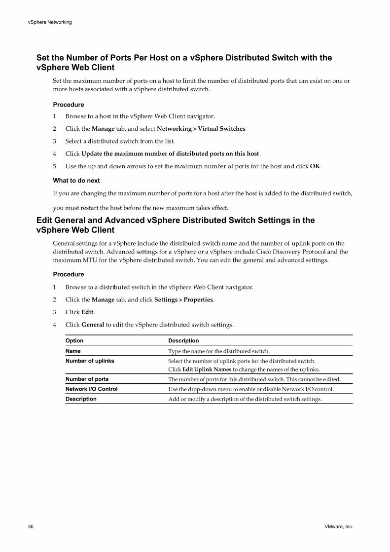
Set the Number of Ports Per Host on a vSphere Distributed Switch with thevSphere Web Client
Set the maximum number of ports on a host to limit the number of distributed ports that can exist on one or
more hosts associated with a vSphere distributed switch.
Procedure
1 Browse to a host in the vSphere Web Client navigator.
2 Click the Manage tab, and select Networking > Virtual Switches
3 Select a distributed switch from the list.
4 Click Update the maximum number of distributed ports on this host.
5 Use the up and down arrows to set the maximum number of ports for the host and click OK.
What to do next
If you are changing the maximum number of ports for a host after the host is added to the distributed switch,
you must restart the host before the new maximum takes effect.
Edit General and Advanced vSphere Distributed Switch Settings in thevSphere Web Client
General settings for a vSphere include the distributed switch name and the number of uplink ports on the
distributed switch. Advanced settings for a vSphere or a vSphere include Cisco Discovery Protocol and the
maximum MTU for the vSphere distributed switch. You can edit the general and advanced settings.
Procedure
1 Browse to a distributed switch in the vSphere Web Client navigator.
2 Click the Manage tab, and click Settings > Properties.
3 Click Edit.
4 Click General to edit the vSphere distributed switch settings.
Option Description
Name Type the name for the distributed switch.
Number of uplinks Select the number of uplink ports for the distributed switch.
Click Edit Uplink Names to change the names of the uplinks.
Number of ports The number of ports for this distributed switch. This cannot be edited.
Network I/O Control Use the drop-down menu to enable or disable Network I/O control.
Description Add or modify a description of the distributed switch settings.
vSphere Networking
36 VMware, Inc.
7/15/2019 Vsphere Esxi Vcenter Server 51 Networking Guide
http://slidepdf.com/reader/full/vsphere-esxi-vcenter-server-51-networking-guide-563280a1ebe2b 37/172
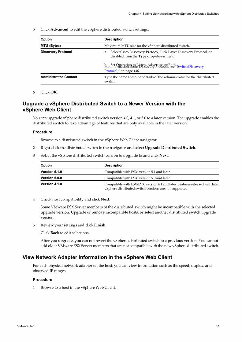
5 Click Advanced to edit the vSphere distributed switch settings.
Option Description
MTU (Bytes) Maximum MTU size for the vSphere distributed switch.
Discovery Protocol a Select Cisco Discovery Protocol, Link Layer Discovery Protocol, ordisabled from the Type drop-down menu.
b Set Operation to Listen, Advertise, or Both.For information about Discovery Protocol, see “Switch DiscoveryProtocol,” on page 146.
Administrator Contact Type the name and other details of the administrator for the distributedswitch.
6 Click OK.
Upgrade a vSphere Distributed Switch to a Newer Version with thevSphere Web Client
You can upgrade vSphere distributed switch version 4.0, 4.1, or 5.0 to a later version. The upgrade enables the
distributed switch to take advantage of features that are only available in the later version.
Procedure
1 Browse to a distributed switch in the vSphere Web Client navigator.
2 Right-click the distributed switch in the navigator and select Upgrade Distributed Switch.
3 Select the vSphere distributed switch version to upgrade to and click Next.
Option Description
Version 5.1.0 Compatible with ESXi version 5.1 and later.
Version 5.0.0 Compatible with ESXi version 5.0 and later.
Version 4.1.0 Compatible with ESX/ESXi version 4.1 and later. Features released with latervSphere distributed switch versions are not supported.
4 Check host compatibility and click Next.
Some VMware ESX Server members of the distributed switch might be incompatible with the selected
upgrade version. Upgrade or remove incompatible hosts, or select another distributed switch upgrade
version.
5 Review your settings and click Finish.
Click Back to edit selections.
After you upgrade, you can not revert the vSphere distributed switch to a previous version. You cannot
add older VMware ESX Server members that are not compatible with the new vSphere distributed switch.
View Network Adapter Information in the vSphere Web Client
For each physical network adapter on the host, you can view information such as the speed, duplex, and
observed IP ranges.
Procedure
1 Browse to a host in the vSphere Web Client.
Chapter 4 Setting Up Networking with vSphere Distributed Switches
VMware, Inc. 37
7/15/2019 Vsphere Esxi Vcenter Server 51 Networking Guide
http://slidepdf.com/reader/full/vsphere-esxi-vcenter-server-51-networking-guide-563280a1ebe2b 38/172
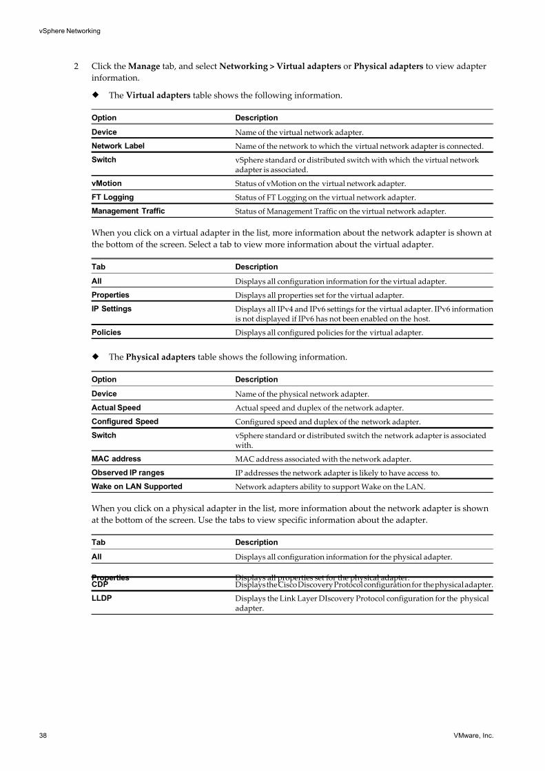
2 Click the Manage tab, and select Networking > Virtual adapters or Physical adapters to view adapter
information.
u The Virtual adapters table shows the following information.
Option Description
Device Name of the virtual network adapter.
Network Label Name of the network to which the virtual network adapter is connected.
Switch vSphere standard or distributed switch with which the virtual networkadapter is associated.
vMotion Status of vMotion on the virtual network adapter.
FT Logging Status of FT Logging on the virtual network adapter.
Management Traffic Status of Management Traffic on the virtual network adapter.
When you click on a virtual adapter in the list, more information about the network adapter is shown at
the bottom of the screen. Select a tab to view more information about the virtual adapter.
Tab Description
All Displays all configuration information for the virtual adapter.
Properties Displays all properties set for the virtual adapter.
IP Settings Displays all IPv4 and IPv6 settings for the virtual adapter. IPv6 informationis not displayed if IPv6 has not been enabled on the host.
Policies Displays all configured policies for the virtual adapter.
u The Physical adapters table shows the following information.
Option Description
Device Name of the physical network adapter.
Actual Speed Actual speed and duplex of the network adapter.
Configured Speed Configured speed and duplex of the network adapter.
Switch vSphere standard or distributed switch the network adapter is associatedwith.
MAC address MAC address associated with the network adapter.
Observed IP ranges IP addresses the network adapter is likely to have access to.
Wake on LAN Supported Network adapters ability to support Wake on the LAN.
When you click on a physical adapter in the list, more information about the network adapter is shown
at the bottom of the screen. Use the tabs to view specific information about the adapter.
Tab Description
All Displays all configuration information for the physical adapter.
Properties Displays all properties set for the physical adapter.CDP Displays the Cisco Discovery Protocol configuration for the physical adapter.
LLDP Displays the Link Layer DIscovery Protocol configuration for the physicaladapter.
vSphere Networking
38 VMware, Inc.
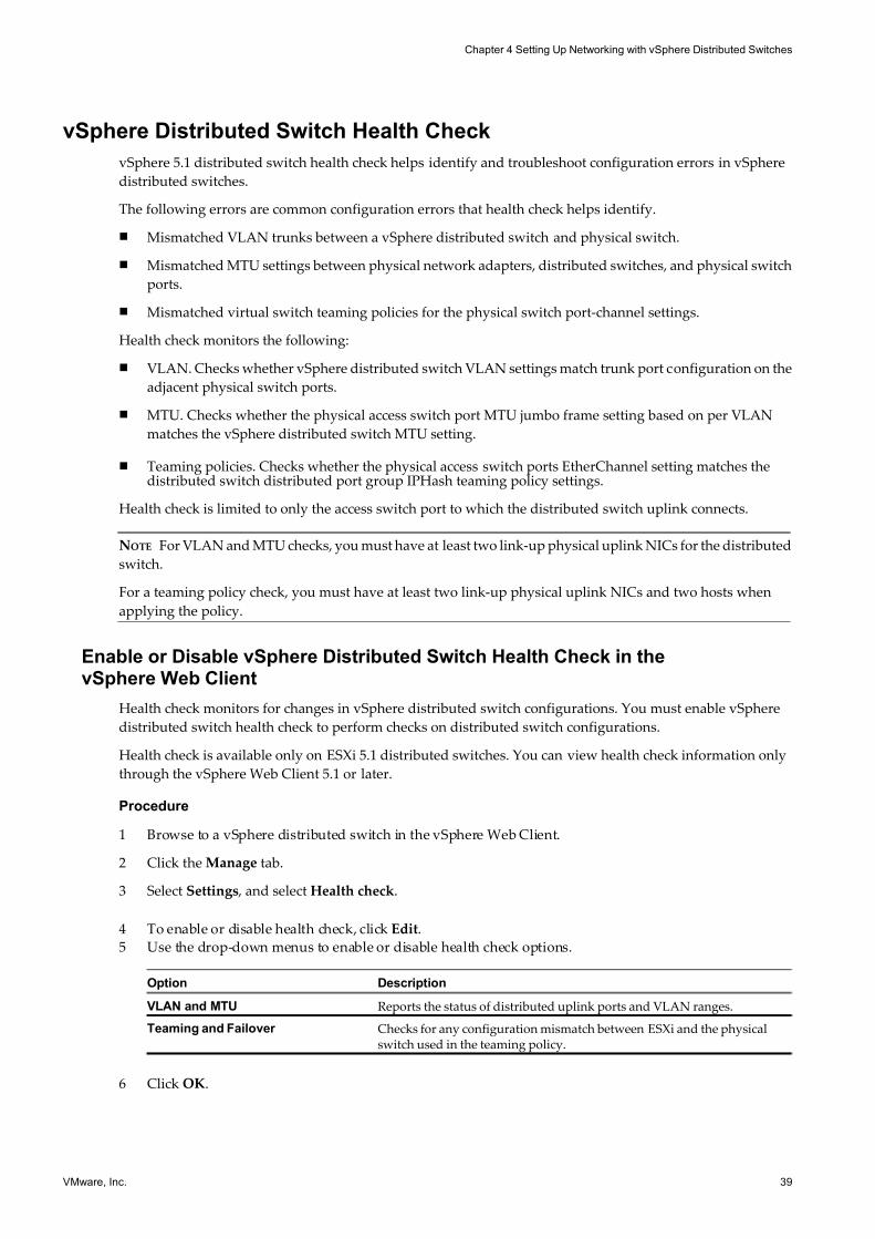
7/15/2019 Vsphere Esxi Vcenter Server 51 Networking Guide
http://slidepdf.com/reader/full/vsphere-esxi-vcenter-server-51-networking-guide-563280a1ebe2b 39/172
vSphere Distributed Switch Health Check
vSphere 5.1 distributed switch health check helps identify and troubleshoot configuration errors in vSphere
distributed switches.
The following errors are common configuration errors that health check helps identify.
n Mismatched VLAN trunks between a vSphere distributed switch and physical switch.
n Mismatched MTU settings between physical network adapters, distributed switches, and physical switch
ports.
n Mismatched virtual switch teaming policies for the physical switch port-channel settings.
Health check monitors the following:
n VLAN. Checks whether vSphere distributed switch VLAN settings match trunk port configuration on the
adjacent physical switch ports.
n MTU. Checks whether the physical access switch port MTU jumbo frame setting based on per VLAN
matches the vSphere distributed switch MTU setting.
n Teaming policies. Checks whether the physical access switch ports EtherChannel setting matches thedistributed switch distributed port group IPHash teaming policy settings.
Health check is limited to only the access switch port to which the distributed switch uplink connects.
NOTE For VLAN and MTU checks, you must have at least two link-up physical uplink NICs for the distributed
switch.
For a teaming policy check, you must have at least two link-up physical uplink NICs and two hosts when
applying the policy.
Enable or Disable vSphere Distributed Switch Health Check in thevSphere Web Client
Health check monitors for changes in vSphere distributed switch configurations. You must enable vSphere
distributed switch health check to perform checks on distributed switch configurations.
Health check is available only on ESXi 5.1 distributed switches. You can view health check information only
through the vSphere Web Client 5.1 or later.
Procedure
1 Browse to a vSphere distributed switch in the vSphere Web Client.
2 Click the Manage tab.
3 Select Settings , and select Health check.
4 To enable or disable health check, click Edit.
5 Use the drop-down menus to enable or disable health check options.
Option Description
VLAN and MTU Reports the status of distributed uplink ports and VLAN ranges.
Teaming and Failover Checks for any configuration mismatch between ESXi and the physicalswitch used in the teaming policy.
6 Click OK.
Chapter 4 Setting Up Networking with vSphere Distributed Switches
VMware, Inc. 39
7/15/2019 Vsphere Esxi Vcenter Server 51 Networking Guide
http://slidepdf.com/reader/full/vsphere-esxi-vcenter-server-51-networking-guide-563280a1ebe2b 40/172
What to do next
When you change the configuration of a vSphere distributed switch, you can view information about the
change in the Monitor tab in the vSphere Web Client. See “View vSphere Distributed Switch Health Check
Information,” on page 40.
View vSphere Distributed Switch Health Check Information
Once you have enabled health check, you can view vSphere distributed switch health check information in the
vSphere Web Client.
Prerequisites
Enable health check on each vSphere distributed switch. See “Enable or Disable vSphere Distributed Switch
Health Check in the vSphere Web Client,” on page 39.
Procedure
1 Browse to a vSphere distributed switch in the vSphere Web Client.
2 Click the Monitor tab and click Health.
3 In the Health Status Details section, click a tab to view the health status of the selected check.
The three tabs include: VLAN , MTU , and Teaming and Failover.
Export, Import, and Restore Distributed Switch Configurations
You can export vSphere distributed switch configurations to the client, including distributed port group
configurations. The configuration preserves valid network configurations, enabling distribution of these
configurations to other deployments.
You can only import or export distributed switch or distributed port group configurations. To import, export,
or restore a port group configuration, see “Export, Import, and Restore vSphere Distributed Port Group
Configurations,” on page 47.
Export vSphere Distributed Switch Configurations with the vSphere Web Client
You can export vSphere distributed switch and distributed port group configurations to a file. The file preserves
valid network configurations, enabling distribution of these configurations to other deployments
This functionality is available only with the vSphere Web Client 5.1 or later. However, you can export settings
from any version of a distributed switch if you use the vSphere Web Client or later.
Procedure
1 Browse to a distributed switch in the vSphere Web Client navigator.
2 Right-click the distributed switch in the navigator and select All vCenter Actions > Export
Configuration.
3 Choose to export the distributed switch configuration, or export the distributed switch configuration and
all port groups.
4 (Optional) Enter notes about this configuration in the Descriptions field.
5 Click OK.
6 Click Yes to save the configuration file to your local system.
vSphere Networking
40 VMware, Inc.
7/15/2019 Vsphere Esxi Vcenter Server 51 Networking Guide
http://slidepdf.com/reader/full/vsphere-esxi-vcenter-server-51-networking-guide-563280a1ebe2b 41/172
You now have a configuration file that contains all the settings for the selected distributed switch and
distributes port group. You can use this file to create multiple copies of this configuration on an existing
deployment, or overwrite settings of existing distributed switches and port groups to conform to the selected
settings.
What to do next
Use the exported configuration file to do the following tasks:n To create a copy of the exported distributed switch, see “Import a vSphere Distributed Switch
Configuration with the vSphere Web Client,” on page 41.
n To overwrite settings on an existing distributed switch, see “Restore a vSphere Distributed Switch
Configuration with the vSphere Web Client,” on page 41.
You can also export, import, and restore only port group configurations. See “Export, Import, and Restore
vSphere Distributed Port Group Configurations,” on page 47.
Import a vSphere Distributed Switch Configuration with the vSphere Web Client
Use the Import function to create a distributed switch from an exported configuration file. The configuration
file contains valid network configurations, enabling distribution of these configurations to other deployments.This functionality is available only with the vSphere Web Client 5.1 or later. However, you can import settings
from any version of distributed switch if you use the vSphere Web Client 5.1 or later.
Procedure
1 Browse to a datacenter In the vSphere Web Client navigator.
2 Right-click the datacenter in the navigator and select All vCenter Actions > Import Distributed Switch.
3 Browse to the location of your saved configuration file.
4 Select the Preserve original distributed switch and port group identifiers check box.
5 Click Next.
If you entered notes about the saved configuration file, they appear in the Notes section.
6 Review the import settings before completing the import.
7 Click Finish.
A new distributed switch is created with configuration settings from the configuration file. If you included
distributed port group information in your configuration file, the distribute port groups are also created.
Restore a vSphere Distributed Switch Configuration with thevSphere Web Client
Use the restore option to reset the configuration of an existing distributed switch to the settings in the
configuration file. Restoring a distributed switch changes the settings on the selected switch back to the settingssaved in the configuration file.
This functionality is available only with the vSphere Web Client 5.1 or later. However, you can restore settings
from any distributed switch version if you use the vSphere Web Client 5.1 or later.
Procedure
1 Broswe to a distributed switch in the vSphere Web Client navigator.
2 Right-click the distributed switch in the navigator and select All vCenter Actions > Restore
Configuration.
Chapter 4 Setting Up Networking with vSphere Distributed Switches
VMware, Inc. 41

7/15/2019 Vsphere Esxi Vcenter Server 51 Networking Guide
http://slidepdf.com/reader/full/vsphere-esxi-vcenter-server-51-networking-guide-563280a1ebe2b 42/172
3 Browse for the configuration backup file to use.
4 Select Restore distributed switch and all port groups or Restore distributed switch only and click Next
5 Review the summary information for the restore.
Restoring a distributed switch will overwrite the current settings of the distributed switch and its port
groups. It will not delete existing port groups that are not part of the configuration file.
6 Click Finish.
The distributed switch configuration has been restored to the settings in the configuration file.
Distributed Port Groups
A distributed port group specifies port configuration options for each member port on a vSphere distributed
switch. Distributed port groups define how a connection is made to a network.
Add a Distributed Port Group
Add a distributed port group to a vSphere distributed switch to create a distributed switch network for your
virtual machines.
Procedure
1 Log in to the vSphere Client and select the Networking inventory view.
2 Select Inventory > vSphere Distributed Switch > New Port Group.
3 Enter a Name and the Number of Ports for your new distributed port group.
4 Select a VLAN Type.
Option Description
None Do not use VLAN.
VLAN In the VLAN ID field, enter a number between 1 and 4094.
VLAN Trunking Enter a VLAN trunk range.
Private VLAN Select a private VLAN entry. If you did not create any private VLANs, thismenu is empty.
5 Click Next.
6 Click Finish.
Add a Distributed Port Group in the vSphere Web Client
Add a distributed port group to a vSphere distributed switch to create a distributed switch network for your
virtual machines.
Procedure
1 Browse to a distributed switch in the vSphere Web Client.
2 Right-click the distributed switch in the navigator and select New distributed port group.
3 In the Select name and location section, type the name of the new distributed port group, or accept the
generated name, and click Next.
vSphere Networking
42 VMware, Inc.
7/15/2019 Vsphere Esxi Vcenter Server 51 Networking Guide
http://slidepdf.com/reader/full/vsphere-esxi-vcenter-server-51-networking-guide-563280a1ebe2b 43/172
4 In the Configure settings section, set the general properties for the new distributed port group and click
Next.
Setting Description
Port binding Choose when ports are assigned to virtual machines connected to thisdistributed port group.
n Static binding: Assign a port to a virtual machine when the virtualmachine connects to the distributed port group. This option is notavailable when the vSphere Web Client is connected directly to ESXi.
n Dynamic binding: Assign a port to a virtual machine the first time thevirtual machine powers on after it is connected to the distributed portgroup. Dynamic binding is deprecated in ESXi 5.0.
n Ephemeral: No port binding. This option is not available when thevSphere Web Client is connected directly to ESXi.
Port allocation n Elastic: The default number of ports is eight. When all ports are assigned,a new set of eight ports is created. This is the default.
n Fixed: The default number of ports is set to eight. No additional portsare created when all ports are assigned.
Number of ports Enter the number of ports on the distributed port group.
Network resource pool Use the drop-down menu to assign the new distributed port group to a user-defined network resource pool. If you have not created a network resourcepool, this menu is empty.
VLAN Use the Type drop-down menu to select VLAN options:
n None: Do not use VLAN.
n VLAN: In the VLAN ID field, enter a number between 1 and 4094.
n VLAN Trunking: Enter a VLAN trunk range.
n Private VLAN: Select a private VLAN entry. If you did not create anyprivate VLANs, this menu is empty.
Advanced Select this check box to customize the policy configurations for the newdistributed port group.
5 (Optional) In the Security section, edit the security exceptions and click Next.
Setting Description
Promiscuous mode n Reject. Placing a guest adapter in promiscuous mode has no effect onwhich frames are received by the adapter.
n Accept. Placing a guest adapter in promiscuous mode causes it to detectall frames passed on the vSphere distributed switch. These frames areallowed under the VLAN policy for the port group to which the adapteris connected.
MAC address changes n Reject. If you set to Reject and the guest operating system changes theMAC address of the adapter to anything other than what is in the .vmx
configuration file, all inbound frames are dropped.
If the Guest OS changes the MAC address back to match the MACaddress in the .vmx configuration file, inbound frames are passed again.
n Accept. Changing the MAC address from the Guest OS has the intendedeffect: frames to the new MAC address are received.
Forged transmits n Reject. Any outbound frame with a source MAC address that is differentfrom the one currently set on the adapter is dropped.
n Accept. No filtering is performed and all outbound frames are passed.
Chapter 4 Setting Up Networking with vSphere Distributed Switches
VMware, Inc. 43
7/15/2019 Vsphere Esxi Vcenter Server 51 Networking Guide
http://slidepdf.com/reader/full/vsphere-esxi-vcenter-server-51-networking-guide-563280a1ebe2b 44/172
6 (Optional) In the Traffic shaping section, enable or disable Ingress or Egress traffic shaping and click
Next.
Setting Description
Status If you enable either Ingress Traffic Shaping or Egress Traffic Shaping , youare setting limits on the amount of networking bandwidth allocated for eachvirtual adapter associated with this particular port group. If you disable the
policy, services have a free, clear connection to the physical network bydefault.
Average Bandwidth Establishes the number of bits per second to allow across a port, averagedover time. This is the allowed average load.
Peak Bandwidth The maximum number of bits per second to allow across a port when it issending and receiving a burst of traffic. This tops the bandwidth used by aport whenever it is using its burst bonus.
Burst Size The maximum number of bytes to allow in a burst. If this parameter is set, aport might gain a burst bonus when it does not use all its allocated bandwidth. Whenever the port needs more bandwidth than specified byAverage Bandwidth , it might temporarily transmit data at a higher speed ifa burst bonus is available. This parameter tops the number of bytes that might be accumulated in the burst bonus and thus transferred at a higher speed.
7 (Optional) In the Teaming and failover section, edit the settings and click Next.
Setting Description
Load balancing Specify how to choose an uplink.
n Route based on the originating virtual port. Choose an uplink based onthe virtual port where the traffic entered the distributed switch.
n Route based on IP hash. Choose an uplink based on a hash of the sourceand destination IP addresses of each packet. For non-IP packets,whatever is at those offsets is used to compute the hash.
n Route based on source MAC hash. Choose an uplink based on a hashof the source Ethernet.
n Route based on physical NIC load. Choose an uplink based on the
current loads of physical NICs.n Use explicit failover order. Always use the highest order uplink from
the list of Active adapters which passes failover detection criteria.
NOTE IP-based teaming requires that the physical switch be configured withetherchannel. For all other options, disable etherchannel.
Network failover detection Specify the method to use for failover detection.
n Link Status only. Relies solely on the link status that the network adapterprovides. This option detects failures, such as cable pulls and physicalswitch power failures, but not configuration errors, such as a physicalswitch port being blocked by spanning tree or that is misconfigured tothe wrong VLAN or cable pulls on the other side of a physical switch.
n Beacon Probing. Sends out and listens for beacon probes on all NICs inthe team and uses this information, in addition to link status, todetermine link failure. This detects many of the failures previously
mentioned that are not detected by link status alone.
NOTE Do not use beacon probing with IP-hash load balancing.
Notify switches Select Yes or No to notify switches in the case of failover. If you select Yes ,whenever a virtual NIC is connected to the distributed switch or wheneverthat virtual NIC’s traffic would be routed over a different physical NIC inthe team because of a failover event, a notification is sent out over thenetwork to update the lookup tables on physical switches. In almost all cases,this process is desirable for the lowest latency of failover occurrences andmigrations with vMotion.
NOTE Do not use this option when the virtual machines using the port groupare using Microsoft Network Load Balancing in unicast mode. No such issueexists with NLB running in multicast mode.
vSphere Networking
44 VMware, Inc.
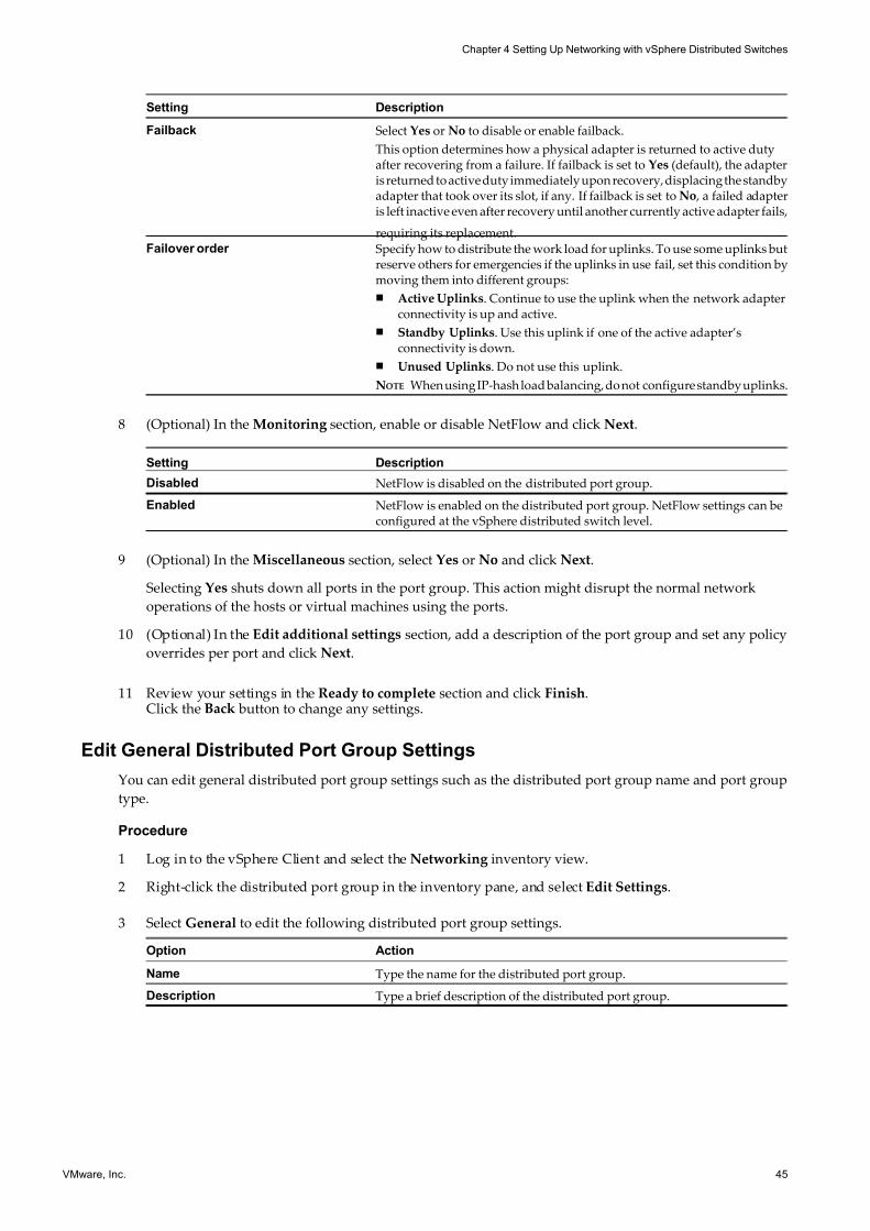
7/15/2019 Vsphere Esxi Vcenter Server 51 Networking Guide
http://slidepdf.com/reader/full/vsphere-esxi-vcenter-server-51-networking-guide-563280a1ebe2b 45/172
Setting Description
Failback Select Yes or No to disable or enable failback.
This option determines how a physical adapter is returned to active dutyafter recovering from a failure. If failback is set to Yes (default), the adapteris returned to active duty immediately upon recovery, displacing the standbyadapter that took over its slot, if any. If failback is set to No , a failed adapteris left inactive even after recovery until another currently active adapter fails,
requiring its replacement.Failover order Specify how to distribute the work load for uplinks. To use some uplinks but
reserve others for emergencies if the uplinks in use fail, set this condition bymoving them into different groups:
n Active Uplinks. Continue to use the uplink when the network adapterconnectivity is up and active.
n Standby Uplinks. Use this uplink if one of the active adapter’sconnectivity is down.
n Unused Uplinks. Do not use this uplink.
NOTE When using IP-hash load balancing, do not configure standby uplinks.
8 (Optional) In the Monitoring section, enable or disable NetFlow and click Next.
Setting Description
Disabled NetFlow is disabled on the distributed port group.
Enabled NetFlow is enabled on the distributed port group. NetFlow settings can beconfigured at the vSphere distributed switch level.
9 (Optional) In the Miscellaneous section, select Yes or No and click Next.
Selecting Yes shuts down all ports in the port group. This action might disrupt the normal network
operations of the hosts or virtual machines using the ports.
10 (Optional) In the Edit additional settings section, add a description of the port group and set any policy
overrides per port and click Next.
11 Review your settings in the Ready to complete section and click Finish.Click the Back button to change any settings.
Edit General Distributed Port Group Settings
You can edit general distributed port group settings such as the distributed port group name and port group
type.
Procedure
1 Log in to the vSphere Client and select the Networking inventory view.
2 Right-click the distributed port group in the inventory pane, and select Edit Settings.
3 Select General to edit the following distributed port group settings.
Option Action
Name Type the name for the distributed port group.
Description Type a brief description of the distributed port group.
Chapter 4 Setting Up Networking with vSphere Distributed Switches
VMware, Inc. 45
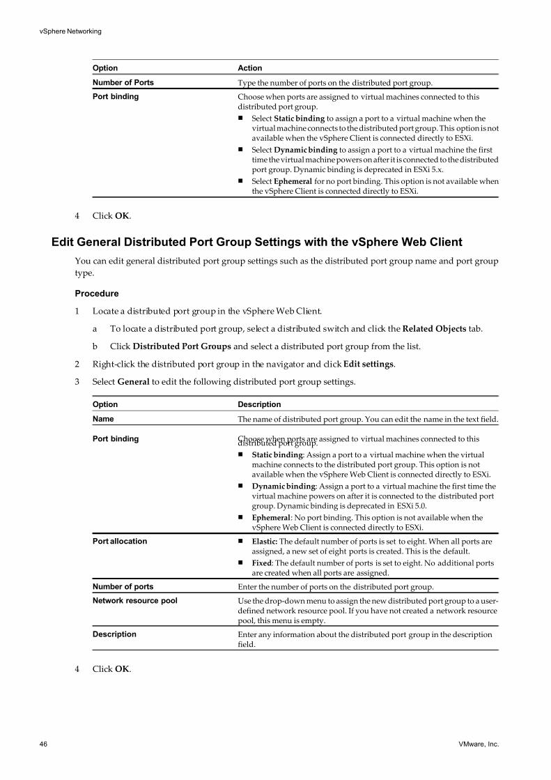
7/15/2019 Vsphere Esxi Vcenter Server 51 Networking Guide
http://slidepdf.com/reader/full/vsphere-esxi-vcenter-server-51-networking-guide-563280a1ebe2b 46/172
Option Action
Number of Ports Type the number of ports on the distributed port group.
Port binding Choose when ports are assigned to virtual machines connected to thisdistributed port group.
n Select Static binding to assign a port to a virtual machine when thevirtual machine connects to the distributed port group. This option is notavailable when the vSphere Client is connected directly to ESXi.
n Select Dynamic binding to assign a port to a virtual machine the firsttime the virtual machine powers on after it is connected to the distributedport group. Dynamic binding is deprecated in ESXi 5.x.
n Select Ephemeral for no port binding. This option is not available whenthe vSphere Client is connected directly to ESXi.
4 Click OK.
Edit General Distributed Port Group Settings with the vSphere Web Client
You can edit general distributed port group settings such as the distributed port group name and port group
type.
Procedure
1 Locate a distributed port group in the vSphere Web Client.
a To locate a distributed port group, select a distributed switch and click the Related Objects tab.
b Click Distributed Port Groups and select a distributed port group from the list.
2 Right-click the distributed port group in the navigator and click Edit settings.
3 Select General to edit the following distributed port group settings.
Option Description
Name The name of distributed port group. You can edit the name in the text field.
Port binding Choose when ports are assigned to virtual machines connected to thisdistributed port group.
n Static binding: Assign a port to a virtual machine when the virtualmachine connects to the distributed port group. This option is notavailable when the vSphere Web Client is connected directly to ESXi.
n Dynamic binding: Assign a port to a virtual machine the first time thevirtual machine powers on after it is connected to the distributed portgroup. Dynamic binding is deprecated in ESXi 5.0.
n Ephemeral: No port binding. This option is not available when thevSphere Web Client is connected directly to ESXi.
Port allocation n Elastic: The default number of ports is set to eight. When all ports areassigned, a new set of eight ports is created. This is the default.
n Fixed: The default number of ports is set to eight. No additional portsare created when all ports are assigned.
Number of ports Enter the number of ports on the distributed port group.
Network resource pool Use the drop-down menu to assign the new distributed port group to a user-defined network resource pool. If you have not created a network resourcepool, this menu is empty.
Description Enter any information about the distributed port group in the descriptionfield.
4 Click OK.
vSphere Networking
46 VMware, Inc.
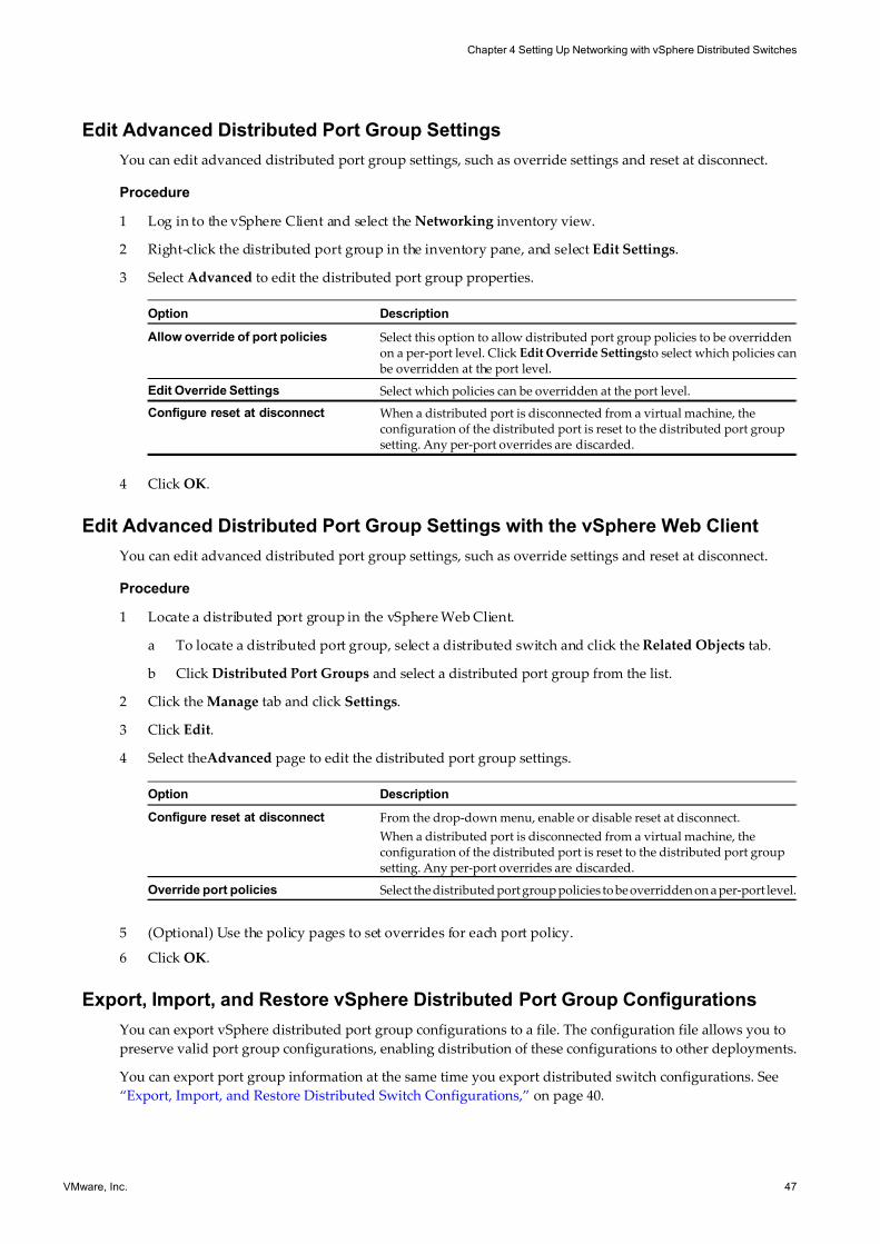
7/15/2019 Vsphere Esxi Vcenter Server 51 Networking Guide
http://slidepdf.com/reader/full/vsphere-esxi-vcenter-server-51-networking-guide-563280a1ebe2b 47/172
Edit Advanced Distributed Port Group Settings
You can edit advanced distributed port group settings, such as override settings and reset at disconnect.
Procedure
1 Log in to the vSphere Client and select the Networking inventory view.
2 Right-click the distributed port group in the inventory pane, and select Edit Settings.
3 Select Advanced to edit the distributed port group properties.
Option Description
Allow override of port policies Select this option to allow distributed port group policies to be overriddenon a per-port level. Click Edit Override Settingsto select which policies can be overridden at the port level.
Edit Override Settings Select which policies can be overridden at the port level.
Configure reset at disconnect When a distributed port is disconnected from a virtual machine, theconfiguration of the distributed port is reset to the distributed port groupsetting. Any per-port overrides are discarded.
4 Click OK.
Edit Advanced Distributed Port Group Settings with the vSphere Web Client
You can edit advanced distributed port group settings, such as override settings and reset at disconnect.
Procedure
1 Locate a distributed port group in the vSphere Web Client.
a To locate a distributed port group, select a distributed switch and click the Related Objects tab.
b Click Distributed Port Groups and select a distributed port group from the list.
2 Click the Manage tab and click Settings.
3 Click Edit.
4 Select theAdvanced page to edit the distributed port group settings.
Option Description
Configure reset at disconnect From the drop-down menu, enable or disable reset at disconnect.
When a distributed port is disconnected from a virtual machine, theconfiguration of the distributed port is reset to the distributed port groupsetting. Any per-port overrides are discarded.
Override port policies Select the distributed port group policies to be overridden on a per-port level.
5 (Optional) Use the policy pages to set overrides for each port policy.
6 Click OK.
Export, Import, and Restore vSphere Distributed Port Group Configurations
You can export vSphere distributed port group configurations to a file. The configuration file allows you to
preserve valid port group configurations, enabling distribution of these configurations to other deployments.
You can export port group information at the same time you export distributed switch configurations. See
“Export, Import, and Restore Distributed Switch Configurations,” on page 40.
Chapter 4 Setting Up Networking with vSphere Distributed Switches
VMware, Inc. 47
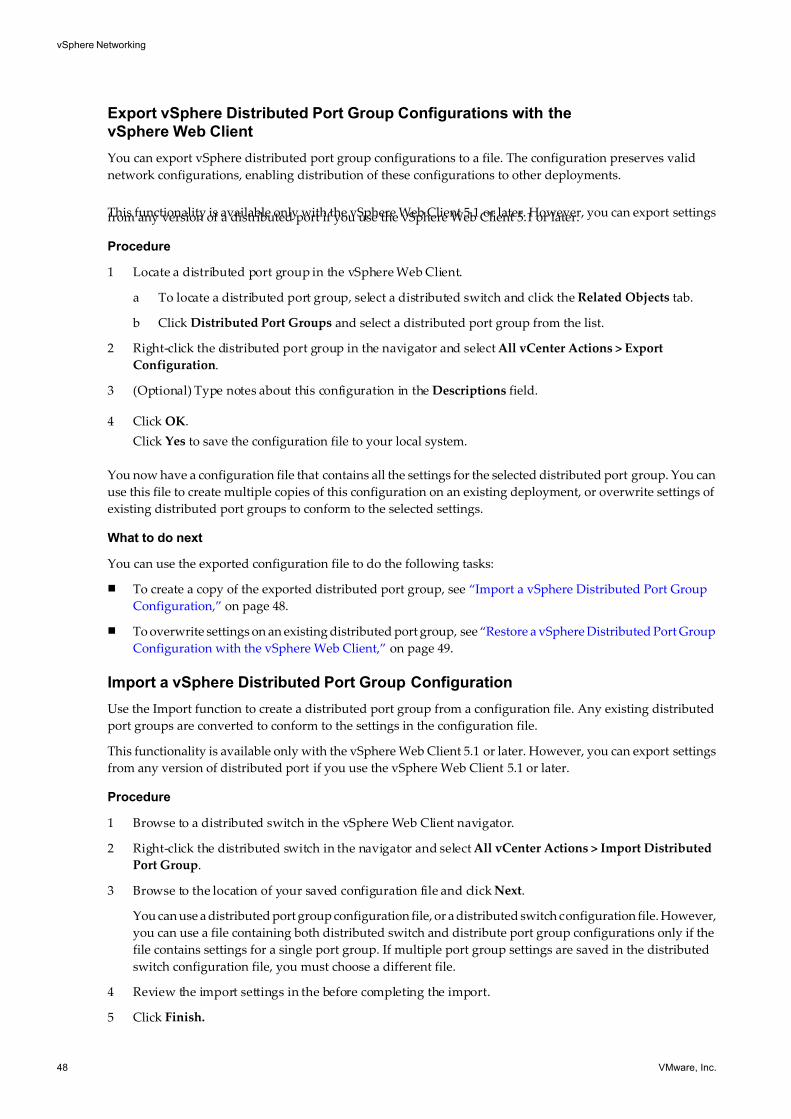
7/15/2019 Vsphere Esxi Vcenter Server 51 Networking Guide
http://slidepdf.com/reader/full/vsphere-esxi-vcenter-server-51-networking-guide-563280a1ebe2b 48/172
Export vSphere Distributed Port Group Configurations with the
vSphere Web Client
You can export vSphere distributed port group configurations to a file. The configuration preserves valid
network configurations, enabling distribution of these configurations to other deployments.
This functionality is available only with the vSphere Web Client 5.1 or later. However, you can export settingsfrom any version of a distributed port if you use the vSphere Web Client 5.1 or later.
Procedure
1 Locate a distributed port group in the vSphere Web Client.
a To locate a distributed port group, select a distributed switch and click the Related Objects tab.
b Click Distributed Port Groups and select a distributed port group from the list.
2 Right-click the distributed port group in the navigator and select All vCenter Actions > Export
Configuration.
3 (Optional) Type notes about this configuration in the Descriptions field.
4 Click OK.
Click Yes to save the configuration file to your local system.
You now have a configuration file that contains all the settings for the selected distributed port group. You can
use this file to create multiple copies of this configuration on an existing deployment, or overwrite settings of
existing distributed port groups to conform to the selected settings.
What to do next
You can use the exported configuration file to do the following tasks:
n To create a copy of the exported distributed port group, see “Import a vSphere Distributed Port Group
Configuration,” on page 48.
n To overwrite settings on an existing distributed port group, see “Restore a vSphere Distributed Port Group
Configuration with the vSphere Web Client,” on page 49.
Import a vSphere Distributed Port Group Configuration
Use the Import function to create a distributed port group from a configuration file. Any existing distributed
port groups are converted to conform to the settings in the configuration file.
This functionality is available only with the vSphere Web Client 5.1 or later. However, you can export settings
from any version of distributed port if you use the vSphere Web Client 5.1 or later.
Procedure
1 Browse to a distributed switch in the vSphere Web Client navigator.
2 Right-click the distributed switch in the navigator and select All vCenter Actions > Import Distributed
Port Group.
3 Browse to the location of your saved configuration file and click Next.
You can use a distributed port group configuration file, or a distributed switch configuration file. However,
you can use a file containing both distributed switch and distribute port group configurations only if the
file contains settings for a single port group. If multiple port group settings are saved in the distributed
switch configuration file, you must choose a different file.
4 Review the import settings in the before completing the import.
5 Click Finish.
vSphere Networking
48 VMware, Inc.
7/15/2019 Vsphere Esxi Vcenter Server 51 Networking Guide
http://slidepdf.com/reader/full/vsphere-esxi-vcenter-server-51-networking-guide-563280a1ebe2b 49/172
Restore a vSphere Distributed Port Group Configuration with the
vSphere Web Client
Use the restore option to reset the configuration of an existing distributed port group to the settings in a
configuration file.
This functionality is available only with the vSphere Web Client 5.1 or later. However, you can restore settingsfrom any version of distributed switch if you use the vSphere Web Client 5.1 or later.
Procedure
1 Locate a distributed port group in the vSphere Web Client.
a To locate a distributed port group, select a distributed switch and click Related Objects.
b Click Distributed Port Group and select a distributed port group from the list.
2 Right-click the distributed port group in the navigator and select All vCenter Actions > Restore
Configuration.
3 Select one of the following and click Next:
u Restore to a previous configuration to restore your port group configuration to a previous snapshotof the port group.
u Restore configuration from a file lets you browse for a configuration file to use. You can choose a
distributed switch configuration file to use here as long as it contains configuration information for
the selected port group.
4 Review the summary information for the restore.
Restoring a distributed port group will overwrite the settings of the current distributed port group. It will
not delete existing port groups that are not part of the configuration file.
5 Click Finish.
Working with Distributed PortsA distributed port is a port on a vSphere distributed switch that connects to the VMkernel or to a virtual
machine's network adapter.
Default distributed port configuration is determined by the distributed port group settings, but some settings
for individual distributed ports can be overridden.
Monitor Distributed Port State
vSphere can monitor distributed ports and provide information on the current state of each port and the port's
runtime statistics.
Procedure
1 Log in to the vSphere Client and select the Networking inventory view.
2 Select the vSphere distributed switch in the inventory pane.
3 On the Ports tab, click Start Monitoring Port State.
The table on the Ports tab for the distributed switch now displays runtime statistics for each distributed port,
including broadcast, multicast, and unicast ingress and egress traffic and packets.
The State column displays the current state for each distributed port.
Chapter 4 Setting Up Networking with vSphere Distributed Switches
VMware, Inc. 49
7/15/2019 Vsphere Esxi Vcenter Server 51 Networking Guide
http://slidepdf.com/reader/full/vsphere-esxi-vcenter-server-51-networking-guide-563280a1ebe2b 50/172
Table 4-1. Distributed Port States
State Description
Link Up The link for this distributed port is up.
Link Down The link for this distributed port is down.
Blocked This distributed port is blocked.
-- The state of this distributed port is currently unavailable.
Monitor Distributed Port State with the vSphere Web Client
vSphere can monitor distributed ports and provide information about the current state and runtime statistics
of each port.
Procedure
1 Locate a distributed port group in the vSphere Web Client.
a To locate a distributed port group, select a distributed switch and click the Related Objects tab.
b Click Distributed Port Groups and select a distributed port group from the list.2 Click the Manage tab, and click Ports.
3 Click Start Monitoring Port State.
The ports table for the distributed port group displays runtime statistics for each distributed port.
The State column displays the current state for each distributed port.
Option Description
Link Up The link for this distributed port is up.
Link Down The link for this distributed port is down.
Blocked This distributed port is blocked.
-- The state of this distributed port is currently unavailable.
Configure Distributed Port Settings
You can change general distributed port settings such as the port name and description.
Procedure
1 Log in to the vSphere Client and select the Networking inventory view.
2 Select the vSphere distributed switch in the inventory pane.
3 On the Ports tab, right-click the port to modify and select Edit Settings.
4 Click General.
5 Modify the port name and description.
6 Click OK.
vSphere Networking
50 VMware, Inc.
7/15/2019 Vsphere Esxi Vcenter Server 51 Networking Guide
http://slidepdf.com/reader/full/vsphere-esxi-vcenter-server-51-networking-guide-563280a1ebe2b 51/172
Configure Distributed Port Settings with the vSphere Web Client
You can change general distributed port settings such as the port name and description.
Procedure
1 Locate a distributed port group in the vSphere Web Client.
a To locate a distributed port group, select a distributed switch and click the Related Objects tab.
b Click Distributed Port Groups and select a distributed port group from the list.
2 Click the Manage tab, and click Ports.
3 Select a distributed port from the table.
Information about the distributed port appears at the bottom of the screen.
4 Click Edit distributed port settings.
5 On the Properties page and policy pages, edit information about the distributed port and click OK.
If overrides are not allowed, the policy options are dimmed.
You can allow overrides at the port level by changing the Advanced settings of the distributed port group.
See “Edit Advanced Distributed Port Group Settings with the vSphere Web Client,” on page 47.
Private VLANs
Private VLANs are used to solve VLAN ID limitations and waste of IP addresses for certain network setups.
A private VLAN is identified by its primary VLAN ID. A primary VLAN ID can have multiple secondary
VLAN IDs associated with it. Primary VLANs are Promiscuous , so that ports on a private VLAN can
communicate with ports configured as the primary VLAN. Ports on a secondary VLAN can be either
Isolated , communicating only with promiscuous ports, or Community , communicating with both
promiscuous ports and other ports on the same secondary VLAN.
To use private VLANs between a host and the rest of the physical network, the physical switch connected to
the host needs to be private VLAN-capable and configured with the VLAN IDs being used by ESXi for the
private VLAN functionality. For physical switches using dynamic MAC+VLAN ID based learning, all
corresponding private VLAN IDs must be first entered into the switch's VLAN database.
To configure distributed ports to use Private VLAN functionality, you must create the necessary Private
VLANs on the vSphere distributed switch to which the distributed ports are connected.
Create a Private VLAN
You can create a private VLAN for use on a vSphere distributed switch and its associated distributed ports.
Procedure
1 Log in to the vSphere Client and select the Networking inventory view.
2 Right-click the vSphere distributed switch in the inventory pane, and select Edit Settings.
3 Select the Private VLAN tab.
4 Under Primary Private VLAN ID, click [Enter a Private VLAN ID here] , and enter the number of the
primary private VLAN.
5 Click anywhere in the dialog box, and then select the primary private VLAN that you just added.
The primary private VLAN you added appears under Secondary Private VLAN ID.
Chapter 4 Setting Up Networking with vSphere Distributed Switches
VMware, Inc. 51
7/15/2019 Vsphere Esxi Vcenter Server 51 Networking Guide
http://slidepdf.com/reader/full/vsphere-esxi-vcenter-server-51-networking-guide-563280a1ebe2b 52/172
6 For each new secondary private VLAN, click [Enter a Private VLAN ID here] under Secondary Private
VLAN ID, and enter the number of the secondary private VLAN.
7 Click anywhere in the dialog box, select the secondary private VLAN that you just added, and select either
Isolated or Community for the port type.
8 Click OK.
Create a Private VLAN in the vSphere Web Client
You can create a private VLAN for use on a vSphere distributed switch and its associated distributed ports.
Procedure
1 Browse to a distributed switch in the vSphere Web Client navigator.
2 Click the Manage tab, and click Settings.
3 Select Private VLAN and click Edit.
4 Click Add to add a Primary VLAN ID to the list.
5 Click up and down arrows to select a primary private VLAN ID.
6 Click the plus sign (+) next to the Primary VLAN ID to add it to the list.
The primary private VLAN also appears under Secondary Private VLAN ID.
7 To add a secondary VLAN, click Add under the Secondary VLAN list, and click the up and down arrows
to enter the number for the secondary VLAN.
8 Click the plus sign (+) next to the Secondary VLAN ID to add it to the list.
9 In the Secondary VLAN type column, click into the column to activate a drop-down menu. Select either
Isolated or Community for the VLAN type.
10 Click OK.
Remove a Primary Private VLANRemove unused primary private VLANs from the networking inventory view of the vSphere Client.
Prerequisites
Before removing a private VLAN, be sure that no port groups are configured to use it.
Procedure
1 Log in to the vSphere Client and select the Networking inventory view.
2 Right-click the vSphere distributed switch in the inventory pane, and select Edit Settings.
3 Select the Private VLAN tab.
4 Select the primary private VLAN to remove.
5 Click Remove under Primary Private VLAN ID, and click OK.
Removing a primary private VLAN also removes all associated secondary private VLANs.
Remove a Primary Private VLAN with the vSphere Web Client
Remove unused primary private VLANs from the distributed settings view of the vSphere Web Client.
Prerequisites
Before you remove a private VLAN, be sure that no port groups are configured to use it.
vSphere Networking
52 VMware, Inc.
7/15/2019 Vsphere Esxi Vcenter Server 51 Networking Guide
http://slidepdf.com/reader/full/vsphere-esxi-vcenter-server-51-networking-guide-563280a1ebe2b 53/172
Procedure
1 Browse to a distributed switch in the vSphere Web Client navigator.
2 Click the Manage tab, and click Settings.
3 Select Private VLAN and click Edit.
4 Select a primary private VLAN to remove.
When you remove a primary private VLAN, you also remove all associated secondary private VLANs.
5 Click Remove under the Primary VLAN ID list.
6 Click OK to verify that you want to remove the primary VLAN.
7 Click OK.
Remove a Secondary Private VLAN
Remove unused secondary private VLANs from the networking inventory view of the vSphere Client.
Prerequisites
Before removing a private VLAN, be sure that no port groups are configured to use it.
Procedure
1 Log in to the vSphere Client and select the Networking inventory view.
2 Right-click the vSphere distributed switch in the inventory pane, and select Edit Settings.
3 Select the Private VLAN tab.
4 Select a primary private VLAN to display its associated secondary private VLANs.
5 Select the secondary private VLAN to remove.
6 Click Remove under Secondary Private VLAN ID, and click OK.
Remove a Secondary Private VLAN with the vSphere Web Client
Remove unused secondary private VLANs from the distributed settings view of the vSphere Web Client.
Prerequisites
Before you remove a private VLAN, be sure that no port groups are configured to use it.
Procedure
1 Browse to a distributed switch in the vSphere Web Client navigator.
2 Click the Manage tab, and select Settings.
3 Select Private VLAN and click Edit.
4 Select a primary private VLAN to display its associated secondary private VLANs.
5 Select a secondary private VLAN to remove.
6 Click Remove under the Secondary VLAN ID list, and click OK.
Chapter 4 Setting Up Networking with vSphere Distributed Switches
VMware, Inc. 53
7/15/2019 Vsphere Esxi Vcenter Server 51 Networking Guide
http://slidepdf.com/reader/full/vsphere-esxi-vcenter-server-51-networking-guide-563280a1ebe2b 54/172
Configuring vSphere Distributed Switch Network Adapters
The vSphere distributed switch networking view of the host configuration page displays the configuration of
the host’s associated vSphere distributed switches and allows you to configure the vSphere distributed switch
network adapters and uplink ports.
Managing Physical Adapters
For each host associated with a vSphere distributed switch, you must assign physical network adapters, or
uplinks, to the vSphere distributed switch. You can assign one uplink on each host per uplink port on the
vSphere distributed switch.
Add an Uplink to a vSphere Distributed Switch
For each host associated with a vSphere distributed switch, you must assign at least one physical network
adapter, or uplink, to the vSphere distributed switch.
Procedure
1 Log in to the vSphere Client and select a host from the inventory panel.The hardware configuration page for the selected host appears.
2 Click the Configuration tab and click Networking.
3 Select the vSphere Distributed Switch view.
4 Click Manage Physical Adapters.
5 Click Click to Add NIC for the uplink port to add an uplink to.
6 Select the physical adapter to add.
If you select an adapter that is attached to another switch, it will be removed from that switch and
reassigned to this vSphere distributed switch.
7 Click OK.
Remove an Uplink from a vSphere Distributed Switch
You can remove an uplink, or physical network adapter, from a vSphere distributed switch.
Procedure
1 Log in to the vSphere Client and select the host from the inventory panel.
The hardware configuration page for this server appears.
2 Click the Configuration tab and click Networking.
3 Select the vSphere Distributed Switch view.
4 Click Manage Physical Adapters.
5 Click Remove to remove the uplink from the vSphere distributed switch.
6 Click OK.
vSphere Networking
54 VMware, Inc.
7/15/2019 Vsphere Esxi Vcenter Server 51 Networking Guide
http://slidepdf.com/reader/full/vsphere-esxi-vcenter-server-51-networking-guide-563280a1ebe2b 55/172
Remove NICs from Active Virtual Machines
When you remove NICs from active virtual machines, you may still see the NICs you removed reported in the
vSphere Client.
Remove NICs from an active virtual machine without a guest operating system installed
You cannot remove NICs from an active virtual machine if the virtual machine has no operating system
installed.
The vSphere Client might report that the NIC has been removed, but you will continue to see it attached to the
virtual machine.
Remove NICs from an active virtual machine with a guest operating system installed
You can remove a NIC from an active virtual machine, but it might not be reported to the vSphere Client for
some time. If you open Edit Settings for the virtual machine, you might still see the NIC that you removed
listed, even when the task is complete. The Edit Settings dialog box for the virtual machine does not
immediately display the removed NIC.
You may also still see the NIC attached to the virtual machine if the guest operating system of the virtual
machine does not support hot-removal of NICs.
Managing Physical Adapters in the vSphere Web Client
Virtual network adapters handle host network services over a vSphere distributed switch.
You can configure VMkernel virtual adapters for a host through an associated vSphere distributed switch
either by creating new virtual adapters or migrating existing virtual adapters.
Add an Uplink to a vSphere Distributed Switch in the vSphere Web Client
For each host associated with a vSphere distributed switch, you must assign at least one physical network
adapter, or uplink, to the vSphere distributed switch.
Procedure
1 Browse to a host in the vSphere Web Client.
2 Click the Manage tab, and select Networking > Virtual Switches.
3 Select a distributed switch to add an uplink to from the list.
4 Click Manage the physical network adapters.
5 Click Add.
6 Select a network adapter from the list and select the Uplink port to assign it to from the drop-down menu.
The selected adapter appears in the Uplink ports list.
7 (Optional) Use the tabs to view information about the uplink.
Tab Description
All Displays all configuration information for the uplink.
Properties Displays all configured properties for the uplink.
CDP Displays the configuration for Cisco Discovery Protocol for the uplink.
LLDP Displays the configuration for Link Layer Discovery Protocol for the uplink.
8 (Optional) Select a vmnic and click Remove to remove a vmnic from an uplink.
9 Click OK.
Chapter 4 Setting Up Networking with vSphere Distributed Switches
VMware, Inc. 55
7/15/2019 Vsphere Esxi Vcenter Server 51 Networking Guide
http://slidepdf.com/reader/full/vsphere-esxi-vcenter-server-51-networking-guide-563280a1ebe2b 56/172
Remove an Uplink from a vSphere Distributed Switch with the vSphere Web Client
You can remove an uplink, or physical network adapter, from a vSphere distributed switch.
Procedure
1 Browse to a host in the vSphere Web Client navigator.
2 Click the Manage tab, and select Networking > Virtual Switches.
3 From the list, select the distributed switch from which you want to remove an uplink.
4 Click Manage the physical network adapters.
5 In the Uplink Ports list, select the adapter that you want to remove, and click Remove.
6 Click OK.
What to do next
When you remove uplinks (physical network adapters) from active virtual machines, you might see the NICs
you removed reported in the vSphere Web Client. See “Remove NICs from Active Virtual Machines,” on
page 55.
Managing Virtual Network Adapters
Virtual network adapters handle host network services over a vSphere distributed switch.
You can configure VMkernel virtual adapters for a host through an associated vSphere distributed switch
either by creating new virtual adapters or migrating existing virtual adapters.
Create a VMkernel Network Adapter on a vSphere Distributed Switch
Create a VMkernel network adapter for use as a vMotion interface or an IP storage port group.
Procedure
1 Log in to the vSphere Client and select the Hosts and Clusters inventory view.
2 Select the host in the inventory pane.
3 On the host Configuration tab, click Networking.
4 Select the vSphere Distributed Switch view.
5 Click Manage Virtual Adapters.
6 Click Add.
7 Select New virtual adapter , and click Next.
8 Select VMkernel and click Next.
9 Choose a distributed port or distributed port group connection for the virtual adapter.
Option Description
Select a port group Choose the distributed port group for the virtual adapter to connect to fromthe drop-down menu.
Select port Type the port ID of the distributed port for the virtual network adapter toconnect to.
vSphere Networking
56 VMware, Inc.
7/15/2019 Vsphere Esxi Vcenter Server 51 Networking Guide
http://slidepdf.com/reader/full/vsphere-esxi-vcenter-server-51-networking-guide-563280a1ebe2b 57/172
10 Select Use this virtual adapter for vMotion to enable this port group to advertise itself to another ESXi
host as the network connection where vMotion traffic is sent.
You can enable this property for only one vMotion and IP storage port group for each host. If this property
is not enabled for any port group, migration with vMotion to this host is not possible.
11 Choose whether to Use this virtual adapter for fault tolerance logging.
12 Choose whether to Use this virtual adapter for management traffic , and click Next.
13 Under IP Settings, specify the IP address and subnet mask.
IPv6 cannot be used with a dependent hardware iSCSI adapter.
14 Click Edit to set the VMkernel default gateway for VMkernel services, such as vMotion, NAS, and iSCSI.
15 On the DNS Configuration tab, the name of the host is entered by default. The DNS server addresses and
domain that were specified during installation are also preselected.
16 On the Routing tab, enter gateway information for the VMkernel. A gateway is needed for connectivity
to machines not on the same IP subnet as the VMkernel.
Static IP settings is the default. Do not use routing with software iSCSI Multipathing configurations or
dependent hardware iSCSI adapters.17 Click OK , and then click Next.
18 Click Finish.
Migrate an Existing Virtual Adapter to a vSphere Distributed Switch
You can migrate an existing virtual adapter from a vSphere standard switch to a vSphere distributed switch.
Procedure
1 Log in to the vSphere Client and select the Hosts and Clusters inventory view.
2 Select the host in the inventory pane.
3 On the host Configuration tab, click Networking.
4 Select the vSphere Distributed Switch view.
5 Click Manage Virtual Adapters.
6 Click Add.
7 Select Migrate existing virtual network adapters and click Next.
8 Select one or more virtual network adapters to migrate.
9 For each selected adapter, choose a port group from the Select a port group drop-down menu.
10 Click Next.
11 Click Finish.
Migrate a Virtual Adapter to a vSphere Standard Switch
You can migrate an existing virtual adapter from a vSphere distributed switch to a vSphere standard switch.
Procedure
1 Log in to the vSphere Client and select the Hosts and Clusters inventory view.
2 Select the host in the inventory pane.
3 On the host Configuration tab, click Networking.
Chapter 4 Setting Up Networking with vSphere Distributed Switches
VMware, Inc. 57
7/15/2019 Vsphere Esxi Vcenter Server 51 Networking Guide
http://slidepdf.com/reader/full/vsphere-esxi-vcenter-server-51-networking-guide-563280a1ebe2b 58/172
4 Select the vSphere Distributed Switch view.
5 Click Manage Virtual Adapters.
6 Select the virtual adapter to migrate, and click Migrate.
7 Select the standard switch to migrate the adapter to and click Next.
8 Enter a Network Label and optionally a VLAN ID for the virtual adapter, and click Next.
9 Click Finish to migrate the virtual adapter and complete the wizard.
Edit VMkernel Configuration on a vSphere Distributed Switch
You can edit a VMkernel virtual network adapter on a vSphere distributed switch to change the IP settings,
such as IP address, subnet mask, default gateway, and DNS configuration. You can also select whether the
virtual adapter is used for vMotion or fault tolerance logging.
Procedure
1 Log in to the vSphere Client and select the Hosts and Clusters inventory view.
2 Select the host in the inventory pane.
3 On the host Configuration tab, click Networking.
4 Select the vSphere Distributed Switch view.
5 Click Manage Virtual Adapters.
6 Select the VMkernel adapter to modify and click Edit.
7 Under Network Connection, select vSphere Distributed Switch and Port Group or Port to add this virtual
adapter to.
8 Select Use this virtual adapter for vMotion to enable this port group to advertise itself to another host as
the network connection that vMotion traffic should be sent through.
You can enable this property for only one vMotion and IP storage port group for each host. If this property
is not enabled for any port group, migration with vMotion to this host is not possible.
9 (Optional) Select Use this virtual adapter for fault tolerance logging.
10 (Optional) Select Use this virtual adapter for management traffic.
11 Under IP Settings, specify the IP Address and Subnet Mask , or select Obtain IP settings automatically .
12 Click Edit to set the VMkernel Default Gateway for VMkernel services, such as vMotion, NAS, and iSCSI.
On the DNS Configuration tab, the name of the host appears in the name field by default. The DNS server
addresses that were specified during installation are also preselected, as is the domain.
On the Routing tab, a gateway is needed for connectivity to machines not on the same IP subnet as the
VMkernel.
Static IP settings is the default.
13 Use the up and down arrows to set the MTU for the VMkernel adapter.
14 Click OK.
vSphere Networking
58 VMware, Inc.
7/15/2019 Vsphere Esxi Vcenter Server 51 Networking Guide
http://slidepdf.com/reader/full/vsphere-esxi-vcenter-server-51-networking-guide-563280a1ebe2b 59/172
View VMkernel Routing Information on a vSphere Distributed Switch
You can view IP and IPv6 routing information, such as network, prefix, and gateway, for a VMkernel network
adapter on a vSphere distributed switch.
Procedure
1 Log in to the vSphere Client and select the Hosts and Clusters inventory view.
2 Select the host in the inventory pane.
3 On the host Configuration tab, click Networking.
4 In the vSphere Distributed Switch view, click Manage Virtual Adapters.
5 Select the VMkernel adapter to view, and click View Routing Table under IP Settings or IPv6 Settings.
A routing table that includes network, prefix, and gateway information for the selected VMkernel adapter
appears.
Remove a Virtual Adapter
Remove a virtual network adapter from a vSphere distributed switch in the Manage Virtual Adapters dialog
box.
Procedure
1 Log in to the vSphere Client and select the host from the inventory panel.
2 Click the Configuration tab and click Networking.
3 Select the vSphere Distributed Switch view.
4 Click Manage Virtual Adapters.
5 Select the virtual adapter to remove and click Remove.
A dialog box appears with the message, Are you sure you want to remove adapter name ?
6 Click Yes.
Managing Virtual Network Adapters in the vSphere Web Client
Virtual network adapters handle host network services over a vSphere distributed switch.
You can configure VMkernel virtual adapters for a host through an associated vSphere distributed switch
either by creating virtual adapters or migrating existing virtual adapters.
Create a VMkernel Network Adapter on a vSphere Distributed Switch in the
vSphere Web Client
Create a VMkernel network adapter for use as a vMotion interface or an IP storage port group.
To add a VMKernel network adapter to a standard switch, see “Set Up VMkernel Networking on a vSphere
Standard Switch with the vSphere Web Client,” on page 19.
Prerequisites
When adding a VMkernel network adapter to a distributed switch, a host must already be associated with the
distributed switch.
Procedure
1 Browse to a host in the vSphere Web Client navigator.
Chapter 4 Setting Up Networking with vSphere Distributed Switches
VMware, Inc. 59
7/15/2019 Vsphere Esxi Vcenter Server 51 Networking Guide
http://slidepdf.com/reader/full/vsphere-esxi-vcenter-server-51-networking-guide-563280a1ebe2b 60/172
2 Right-click the host in the navigator and select All vCenter Actions > Add Networking.
3 On the Select connection type page, select VMkernel Network Adapter and click Next.
4 On the Select target device page, select an existing distributed port group and click Next.
Click Browse to select an existing distributed port group.
5 On the Port properties page, set the VMkernel port settings and click Next.
Setting Description
Network Label Specify this label when you configure VMkernel services such as vMotionand IP storage and you configure a virtual adapter to be attached to this portgroup. This name is generated for a VMKernel on a distributed switch.
IP settings Use the drop-down menu to enable IPv4, IPv6, or both.
NOTE The IPv6 option does not appear on hosts that do not have IPv6enabled.
vMotion Select the check box to enable this port group to advertise itself to anotherESXi host as the network connection where vMotion traffic is sent. You canenable this property for only one vMotion and IP storage port group for eachhost. If this property is not enabled for any port group, migration withvMotion to the selected host is not possible.
Fault Tolerance logging Select the check box to enable fault tolerance logging.
Management traffic Select the check box to enable management traffic.
6 (Optional) On the IPv4 settings page, select the method by which IP addresses are obtained with the drop-
down menu and click Next.
Option Description
Obtain IP settings automatically Use DHCP to obtain IP settings.
Use static IP settings Enter the IPv4 IP address and subnet mask for the VMkernel interface.
The VMkernel Default Gateway for IPv4 is set automatically.
The DNS server addresses that you specified during installation are
preselected, as is the domain.
7 (Optional) On the IPv6 settings page, select an option for obtaining IPv6 addresses and click Next.
Option Description
Obtain IPv6 addresses automatically
through DHCP
Use DHCP to obtain IPv6 addresses.
Obtain IPv6 addresses automatically
through Router Advertisement
Use router advertisement to obtain IPv6 addresses.
Static IPv6 addresses a Click Add to add a new IPv6 address.
b Enter the IPv6 address and subnet prefix length, and click OK.
c To change the VMkernel default gateway, click Edit.
8 Review your setting selections in the Ready to complete section and click Finish.
ClickBack to change any setting.
vSphere Networking
60 VMware, Inc.
7/15/2019 Vsphere Esxi Vcenter Server 51 Networking Guide
http://slidepdf.com/reader/full/vsphere-esxi-vcenter-server-51-networking-guide-563280a1ebe2b 61/172
Migrate an Existing Virtual or Physical Adapter to a vSphere Distributed Switch with
the vSphere Web Client
You can migrate an existing virtual or physical adapter from a vSphere standard switch to a vSphere distributed
switch. You must do this on a per-host basis.
Procedure
1 Browse to a host in the vSphere Web Client navigator.
2 Click the Manage tab, and click Networking > Virtual Switches.
3 Select a distributed switch from the list that you want to use as the destination for your migration.
4 Click Migrate Networking.
5 On the Select physical network adapters page, select the check box next to any physical network adapters
you want to add to the distributed switch.
6 Click the Assign uplink button to assign each physical network adapter an uplink and uplink port group.
7 On the Network connectivity page, assign adapters to a destination port group to migrate them.
8 Click the Assign port group button to assign port groups to each adapter.
9 Review any dependencies that the selected adapters might have.
10 On the Virtual machine networking page, select the Migrate Virtual Machine Networking check box.
11 Select virtual machines, network adapters, or both, to migrate to the distributed switch. Click Assign port
group to assign port groups to selected network adapters and virtual machines.
12 Review your migration settings in the Ready to complete section and click Finish.
ClickBack to change any selections.
Migrate a Virtual Adapter to a vSphere Standard Switch with the
vSphere Web Client
You can migrate an existing virtual adapter from a vSphere distributed switch to a vSphere standard switch.
Procedure
1 Browse to a host in the vSphere Web Client navigator.
2 Click the Manage tab, and select Networking > Virtual Switches.
3 Select a standard switch from the list that you want to use as the destination for your migration.
4 Click Migrate a vertual network adapter.
5 On the Select virtual network adapter page, select the virtual network adapter to migrate to the standard
switch from the list.Information about the adapter appears at the bottom of the dialog box.
6 On the Configure settings page, edit the Network Label and VLAN ID for the network adapter.
7 Review the migration details on the Ready to complete page and click Finish.
Click Back to edit settings.
Chapter 4 Setting Up Networking with vSphere Distributed Switches
VMware, Inc. 61
7/15/2019 Vsphere Esxi Vcenter Server 51 Networking Guide
http://slidepdf.com/reader/full/vsphere-esxi-vcenter-server-51-networking-guide-563280a1ebe2b 62/172
Edit VMkernel Configuration on a vSphere Distributed Switch with the
vSphere Web Client
You can edit a VMkernel virtual network adapter on a vSphere distributed switch to change the IP settings,
such as IP address, subnet mask, default gateway, and DNS configuration. You can also select whether the
virtual adapter is used for vMotion or fault tolerance logging.
Procedure
1 Browse to a host in the vSphere Web Client navigator.
2 Click the Manage tab, and select Networking > Virtual adapters.
3 Select a VMkernel from the list of virtual adapters and click Edit.
4 (Optional) On the Port properties page, enable or disable service by selecting or deselecting check boxes.
Option Description
vMotion traffic Use the check box to enable this port group to advertise itself to anotherESXi host as the network connection where vMotion traffic is sent. You canenable this property for only one vMotion and IP storage port group for each
host. If this property is not enabled for any port group, migration withvMotion to this host is not possible.
Fault Tolerance logging Use the check box to enable fault tolerance logging.
Management traffic Use the check box to enable management traffic.
5 (Optional) On the NIC settings page, click the up and down arrows to set the MTU for the VMkernel
adapter.
6 (Optional) On the IPv4 settings page, edit the IPv4 settings.
Option Description
Obtain IP settings automatically Use DHCP to obtain IP settings.
Use static IP settings Enter the IPv4 IP address and subnet mask for the VMkernel interface.The default gateway for IPv4 is set automatically.
The DNS server addresses you specified during installation are displayed.
7 (Optional) On the IPv6 settings page, edit the IPv6 settings.
NOTE The IPv6 option does not appear on hosts that do not have IPv6 enabled.
Option Description
Obtain IPv6 addresses automatically
through DHCP
Use DHCP to obtain IPv6 addresses.
Obtain IPv6 addresses automatically
through Router Advertisement
Use router advertisement to obtain IPv6 addresses.
Static IPv6 addresses a Click Add to add a new IPv6 address.
b Enter the IPv6 address and subnet prefix length, and click OK.
c Click Edit to change the VMkernel default gateway, .
d To remove a VMkernel default gateway, select the IPv6 address and clickRemove.
8 On the Validate changes page, review dependencies for the network adapter.
9 Click OK.
vSphere Networking
62 VMware, Inc.
7/15/2019 Vsphere Esxi Vcenter Server 51 Networking Guide
http://slidepdf.com/reader/full/vsphere-esxi-vcenter-server-51-networking-guide-563280a1ebe2b 63/172
View VMkernel Routing Information on a vSphere Distributed Switch in the
vSphere Web Client
You can view IPv4 and IPv6 routing information, such as network, prefix, and gateway, for a VMkernel
network adapter on a vSphere distributed switch.
Procedure
1 Browse to a host in the vSphere Web Client navigator.
2 Click the Manage tab, and select Networking > DNS and routing.
3 In the Routing section, click the Routing table link for the VMkernel gateway or IPv6 VMkernel gateway .
The routing table displays the routing information for devices attached to the host.
NOTE The IPv6 option does not appear on hosts that do not have IPv6 enabled.
4 (Optional) Export the list information by clicking the Export icon at the bottom of the dialog box. There
are several options for export.
5 Click Close.
Remove a Virtual Adapter with the vSphere Web Client
Remove a virtual network adapter from a vSphere distributed switch on the virtual network adapters page.
Procedure
1 Browse to a host in the vSphere Web Client navigator.
2 Click the Manage tab, and click Networking > Virtual adapters.
3 Select a VMkernel from the list of virtual network adapters and click Remove.
An alert appear to inform you that removing the adapter will make all services unavailable.
4 Click OK.
Configuring Virtual Machine Networking on a vSphere DistributedSwitch
Connect virtual machines to a vSphere distributed switch either by configuring an individual virtual machine
NIC or migrating groups of virtual machines from the vSphere distributed switch itself.
Connect virtual machines to vSphere distributed switches by connecting their associated virtual network
adapters to distributed port groups. You can do this either for an individual virtual machine by modifying the
virtual machine’s network adapter configuration, or for a group of virtual machines by migrating virtual
machines from an existing virtual network to a vSphere distributed switch.
Migrate Virtual Machines to Or from a vSphere Distributed Switch
In addition to connecting virtual machines to a distributed switch at the individual virtual machine level, you
can migrate a group of virtual machines between a vSphere distributed switch network and a vSphere standard
switch network.
Procedure
1 Log in to the vSphere Client and select the Networking inventory view.
2 Right-click the datacenter and selectMigrate Virtual Machine Networking.
The Migrate Virtual Machine Networking wizard appears.
Chapter 4 Setting Up Networking with vSphere Distributed Switches
VMware, Inc. 63
7/15/2019 Vsphere Esxi Vcenter Server 51 Networking Guide
http://slidepdf.com/reader/full/vsphere-esxi-vcenter-server-51-networking-guide-563280a1ebe2b 64/172
3 Select a Source Network to migrate adapters from.
Option Description
Include all virtual machine network
adapters that are connected to the
following network (Filter by Network)
Migrates virtual machine network adapters from a particular network. Selectthe source network from the Network drop-down menu.
Include all virtual machine network
adapters that are connected to the
following network (Filter by VDS)
Migrates virtual machine network adapters from a network on a particularvSphere distributed switch. To migrate from a network, select Switch andNetwork from the drop-down menus.
Include all virtual machine network
adapters that are not connected to
any network
Migrates virtual machine network adapters that are not connected to anynetwork.
4 Select a Destination Network to migrate adapters to.
Option Description
Filter by Network Migrates virtual machine network adapters to a particular network. Selectthe destination network from the Network drop-down menu.
Filter by VDS Migrates virtual machine network adapters to a network on a particular
vSphere Distritubed Switch. To migrate to a network, select Switch andNetwork from the drop-down menus.
5 Click Next.
6 (Optional) Highlight a virtual machine or adapter to view their details.
7 Select the virtual machines and adapters to migrate to the destination network and click Next.
8 Verify that the source network, destination network, and number of virtual machines to migrate are correct
and click OK.
Migrate Virtual Machines to Or from a vSphere Distributed Switch with thevSphere Web Client
In addition to connecting virtual machines to a distributed switch at the individual virtual machine level, you
can migrate a group of virtual machines between a vSphere distributed switch network and a vSphere standard
switch network.
Procedure
1 Browse to a datacenter in the vSphere Web Client navigator.
2 Right-click the datacenter in the navigator and select Migrate VM to Another Network.
3 Select a source network.
n Select Specific network and use the Browse button to select a specific source network.
nSelect No network to migrate all virtual machine network adapters that are not connected to anyother network.
4 Select a destination network. Use Browse to select a specific destination network and click Next.
5 Select virtual machines from the list to migrate from the source network to the destination network and
click Next.
6 Review your selections and click Finish.
Click Back to edit any selections.
vSphere Networking
64 VMware, Inc.
7/15/2019 Vsphere Esxi Vcenter Server 51 Networking Guide
http://slidepdf.com/reader/full/vsphere-esxi-vcenter-server-51-networking-guide-563280a1ebe2b 65/172
Connect an Individual Virtual Machine to a Distributed Port Group
Connect an individual virtual machine to a vSphere distributed switch by modifying the virtual machine's NIC
configuration.
Procedure
1 Log in to the vSphere Client and select the virtual machine from the inventory panel.
2 On the Summary tab, click Edit Settings.
3 On the Hardware tab, select the virtual network adapter.
4 Select the distributed port group to migrate to from the Network Label drop-down menu, and click OK.
Connect an Individual Virtual Machine to a Distributed Port Group in thevSphere Web Client
Connect an individual virtual machine to a vSphere distributed switch by modifying the NIC configuration
of the virtual machine.
Procedure
1 Locate a virtual machine in the vSphere Web Client.
a To locate a virtual machine, select a datacenter, folder, cluster, resource pool, or host and click the
Related Objects tab.
b Click Virtual Machines and select a virtual machine from the list.
2 Browse to a virtual machine in the vSphere Web Client.
To locate a virtual machine, select a datacenter, folder, cluster, resource pool, or host. Click the Related
Objects tab and click .
3 Click the Manage tab, and select Settings > VM Hardware.
4 Click Edit.
5 Expand the Network adapter section and select a distributed port group from the drop-down menu.
6 Click OK.
Chapter 4 Setting Up Networking with vSphere Distributed Switches
VMware, Inc. 65

7/15/2019 Vsphere Esxi Vcenter Server 51 Networking Guide
http://slidepdf.com/reader/full/vsphere-esxi-vcenter-server-51-networking-guide-563280a1ebe2b 66/172
vSphere Networking
66 VMware, Inc.
7/15/2019 Vsphere Esxi Vcenter Server 51 Networking Guide
http://slidepdf.com/reader/full/vsphere-esxi-vcenter-server-51-networking-guide-563280a1ebe2b 67/172
Managing Network Resources 5vSphere provides several different methods to help you manage your network resources.
This chapter includes the following topics:
n “vSphere Network I/O Control,” on page 67
n “TCP Segmentation Offload and Jumbo Frames,” on page 73
n “NetQueue and Networking Performance,” on page 77
n “DirectPath I/O,” on page 78
n “Single Root I/O Virtualization (SR-IOV),” on page 82
vSphere Network I/O Control
Network resource pools determine the bandwidth that different network traffic types are given on a vSphere
distributed switch.
When network I/O control is enabled, distributed switch traffic is divided into the following predefined
network resource pools: Fault Tolerance traffic, iSCSI traffic, vMotion traffic, management traffic, vSphereReplication (VR) traffic, NFS traffic, and virtual machine traffic.
You can also create custom network resource pools for virtual machine traffic. You can control the bandwidth
each network resource pool is given by setting the physical adapter shares and host limit for each network
resource pool.
The physical adapter shares assigned to a network resource pool determine the share of the total available
bandwidth guaranteed to the traffic associated with that network resource pool. The share of transmit
bandwidth available to a network resource pool is determined by the network resource pool's shares and what
other network resource pools are actively transmitting. For example, if you set your FT traffic and iSCSI traffic
resource pools to 100 shares, while each of the other resource pools is set to 50 shares, the FT traffic and iSCSI
traffic resource pools each receive 25% of the available bandwidth. The remaining resource pools each receive
12.5% of the available bandwidth. These reservations apply only when the physical adapter is saturated.
NOTE The iSCSI traffic resource pool shares do not apply to iSCSI traffic on a dependent hardware iSCSI
adapter.
The host limit of a network resource pool is the upper limit of bandwidth that the network resource pool can
use.
Assigning a QoS priority tag to a network resource pool applies an 802.1p tag to all outgoing packets associated
with that network resource pool.
VMware, Inc. 67
7/15/2019 Vsphere Esxi Vcenter Server 51 Networking Guide
http://slidepdf.com/reader/full/vsphere-esxi-vcenter-server-51-networking-guide-563280a1ebe2b 68/172
n Enable Network I/O Control on a vSphere Distributed Switch on page 68
Enable network resource management to use network resource pools to prioritize network traffic by
type.
n Enable Network I/O Control on a vSphere Distributed Switch with the vSphere Web Client on
page 69
Enable network resource management to use network resource pools to prioritize network traffic by
type.
n Create a Network Resource Pool on page 69
Create user-defined network resource pools for customized network resource management.
n Create a Network Resource Pool with the vSphere Web Client on page 70
Create user-defined network resource pools for customized network resource management.
n Add or Remove Distributed Port Groups from a Network Resource Pool on page 70
Add a distributed port group to a user-defined network resource pool to include in the network resource
pool all virtual machine network traffic from that distributed port group.
n Add or Remove Distributed Port Groups from a Network Resource Pool with the vSphere Web Client
on page 71Add a distributed port group to a user-defined network resource pool to include in the network resource
pool all virtual machine network traffic from that distributed port group.
n Edit Network Resource Pool Settings on page 71
You can change network resource pool settings such as allocated shares and limits for each network
resource pool to change the priority network traffic for that network resource pool is given.
n Edit Network Resource Pool Settings with the vSphere Web Client on page 72
You can change both system and user-defined network resource pool settings to change the priority
network traffic for that network resource pool.
n Delete a Network Resource Pool on page 72
You can delete user-defined network resource pools that are no longer in use.
n Delete a User-Defined Network Resource Pool with the vSphere Web Client on page 73
You can delete user-defined network resource pools that are no longer in use.
Enable Network I/O Control on a vSphere Distributed Switch
Enable network resource management to use network resource pools to prioritize network traffic by type.
Prerequisites
Verify that your datacenter has at least one vSphere distributed switch version 4.1.0 or later.
Procedure
1 Log in to the vSphere Client and select the Networking inventory view.
2 Select the vSphere distributed switch in the inventory pane.
3 On the Resource Allocation tab, click Properties.
4 Select Enable Network I/O Control on this vSphere ditributed switch , and click OK.
vSphere Networking
68 VMware, Inc.

7/15/2019 Vsphere Esxi Vcenter Server 51 Networking Guide
http://slidepdf.com/reader/full/vsphere-esxi-vcenter-server-51-networking-guide-563280a1ebe2b 69/172
Enable Network I/O Control on a vSphere Distributed Switch with thevSphere Web Client
Enable network resource management to use network resource pools to prioritize network traffic by type.
Prerequisites
Verify that your datacenter has at least one vSphere distributed switch version 4.1.0 or later.
Procedure
1 Browse to a distributed switch in the vSphere Web Client navigator.
2 Click the Manage tab, and select Settings > Properties.
3 Click Edit.
4 Select to Enable or Disable network I/O control from the Network I/O Control drop-down menu.
5 Click OK.
Create a Network Resource PoolCreate user-defined network resource pools for customized network resource management.
User-defined network resource pools are available only on vSphere distributed switches version 5.0.0 or later.
Procedure
1 Log in to the vSphere Client and select the Networking inventory view.
2 Select the vSphere distributed switch in the inventory pane.
3 On the Resource Allocationtab, click New Network Resource Pool.
4 Type a Name for the network resource pool.
5 (Optional) Type a Description for the network resource pool.
6 Select the Physical adapter shares for the network resource pool.
Option Description
Custom Type a specific number of shares, from 1 to 100, for this network resourcepool.
High Sets the shares for this resource pool to 100.
Normal Sets the shares for this resource pool to 50.
Low Sets the shares for this resource pool to 25.
7 Set the Host limit for the network resource pool in megabits per second or select Unlimited.
8 (Optional) Select the QoS priority tag for the network resource pool.
9 Click OK.
The new resource pool appears on the Resource Allocation tab under User-defined network resource pools.
What to do next
Add one or more distributed port groups to the network resource pool.
Chapter 5 Managing Network Resources
VMware, Inc. 69
7/15/2019 Vsphere Esxi Vcenter Server 51 Networking Guide
http://slidepdf.com/reader/full/vsphere-esxi-vcenter-server-51-networking-guide-563280a1ebe2b 70/172
Create a Network Resource Pool with the vSphere Web Client
Create user-defined network resource pools for customized network resource management.
User-defined network resource pools are available only on vSphere distributed switches version 5.0.0 or later.
Procedure
1 Browse to a distributed switch in the vSphere Web Client navigator.
2 Click the Manage tab, and click Resource Allocation.
3 Click New.
4 Type a Name for the network resource pool or accept the generated name.
5 (Optional) Type a Description for the network resource pool.
6 Set the Host limit for the network resource pool in megabits per second, or select Unlimited.
7 Select the Physical adapter shares for the network resource pool from the drop-down menu.
Option Description
Low Sets the shares for this resource pool to 25.
Normal Sets the shares for this resource pool to 50.
High Sets the shares for this resource pool to 100.
Custom Aspecific number of shares, from 1 to 100, for this network resource pool.
8 (Optional) Select the QoS tag for the network resource pool.
The QoS priority tag specifies an IEEE 802.1p tag, allowing quality of service at the media access control
level.
9 Click OK.
The new resource pool appears in the User-defined network resource pools section.
What to do next
Add one or more distributed port groups to the network resource pool.
Add or Remove Distributed Port Groups from a Network Resource Pool
Add a distributed port group to a user-defined network resource pool to include in the network resource pool
all virtual machine network traffic from that distributed port group.
Prerequisites
Create one or more network resource pools on the vSphere distributed switch.
Procedure
1 Log in to the vSphere Client and select the Networking inventory view.
2 Select the vSphere distributed switch in the inventory pane.
3 On the Resource Allocation tab, click Manage Port Groups.
4 (Optional) Select the user-defined network resource pool to associate with a single distributed port group
from the Network resource pool drop-down menu or select None to remove that distributed port group
from a user-defined resource pool.
vSphere Networking
70 VMware, Inc.
7/15/2019 Vsphere Esxi Vcenter Server 51 Networking Guide
http://slidepdf.com/reader/full/vsphere-esxi-vcenter-server-51-networking-guide-563280a1ebe2b 71/172
5 (Optional) Select the user-defined network resource pool to associate with multiple distributed port
groups.
a Hold Ctrl to select multiple distributed port groups to modify, and click Assign multiple.
b Select the user-defined network resource pool to associate with the distributed port groups from the
Network Resource Pool drop-down menu, or select None to remove the distributed port groups from
all user-defined resource pools.
6 Click OK.
Add or Remove Distributed Port Groups from a Network Resource Pool with thevSphere Web Client
Add a distributed port group to a user-defined network resource pool to include in the network resource pool
all virtual machine network traffic from that distributed port group.
Prerequisites
Create one or more user-defined network resource pools on the vSphere distributed switch.
Procedure
1 Browse to a distributed switch in the vSphere Web Client.
2 Right-click the distributed switchin the navitgator and select Manage Distributed Port Groups.
3 On the Select port group policies page, select the Resource allocation check box and click Next.
4 On the Select port groups page, select port groups to edit and click Next.
5 On the Configure policies - Resource allocation page, add or remove the distributed switch from the
network resource pool and click Next.
n To add the distributed port group to a resource pool, select a user-defined resource pool from the
Network resource pool drop-down menu.
nTo remove the distributed port group from a resource pool, select default from the Network resourcepool drop-down menu.
NOTE If there are no user-defined network resource pools on the distributed switch, you will only see
default in the drop-down menu.
6 Review your settings on the Ready to Complete page and click Finish.
Use the Back button to change your selections.
Edit Network Resource Pool Settings
You can change network resource pool settings such as allocated shares and limits for each network resource
pool to change the priority network traffic for that network resource pool is given.
Procedure
1 Log in to the vSphere Client and select the Networking inventory view.
2 Select the vSphere distributed switch in the inventory pane.
3 On the Resource Allocation tab, right-click the network resource pool to edit, and select Edit Settings.
Chapter 5 Managing Network Resources
VMware, Inc. 71
7/15/2019 Vsphere Esxi Vcenter Server 51 Networking Guide
http://slidepdf.com/reader/full/vsphere-esxi-vcenter-server-51-networking-guide-563280a1ebe2b 72/172
4 Select the Physical adapter shares for the network resource pool.
Option Description
Custom Enter a specific number of shares, from 1 to 100, for this network resourcepool.
High Sets the shares for this resource pool to 100.
Normal Sets the shares for this resource pool to 50.Low Sets the shares for this resource pool to 25.
5 Set the Host limit for the network resource pool in megabits per second or select Unlimited.
6 (Optional) Select the QoS priority tag from the drop-down menu.
The QoS priority tag specifies an IEEE 802.1p tag, allowing quality of service at the media access control
level
7 Click OK.
Edit Network Resource Pool Settings with the vSphere Web Client
You can change both system and user-defined network resource pool settings to change the priority networktraffic for that network resource pool.
Procedure
1 Browse to a distributed switch in the vSphere Web Client navigator.
2 Click the Manage tab, and click Resource Allocation.
3 Select a network resource pool from the list and click Edit.
4 Edit the Host limit for the network resource pool in megabits per second or select Unlimited.
5 Select an option for the network resource pool from the Physical adapter shares drop-down menu.
Option Description
Low Sets the shares for this resource pool to 25.
Normal Sets the shares for this resource pool to 50.
High Sets the shares for this resource pool to 100.
Custom A specific number of shares, from 1 to 100, for this network resource pool.
6 (Optional) Select a QoS tag for the network resource pool.
The QoS priority tag specifies an IEEE 802.1p tag, allowing quality of service at the media access control
level.
7 Click OK.
Delete a Network Resource Pool
You can delete user-defined network resource pools that are no longer in use.
Prerequisites
Remove all distributed port groups from the network resource pool.
Procedure
1 Log in to the vSphere Client and select the Networking inventory view.
2 Select the vSphere distributed switch in the inventory pane.
vSphere Networking
72 VMware, Inc.
7/15/2019 Vsphere Esxi Vcenter Server 51 Networking Guide
http://slidepdf.com/reader/full/vsphere-esxi-vcenter-server-51-networking-guide-563280a1ebe2b 73/172
3 On the Resource Allocation tab, right-click the user-defined network resource pool to delete, and select
Delete.
4 Click Yes.
Delete a User-Defined Network Resource Pool with the vSphere Web Client
You can delete user-defined network resource pools that are no longer in use.
NOTE You cannot delete a system network resource pool.
Prerequisites
Remove all distributed port groups from the network resource pool.
Procedure
1 Browse to a distributed switch in the vSphere Web Client navigator.
2 Click the Manage tab, and click Resource Allocation.
3 Select a user-defined resource allocation pool and click Remove.
4 Click Yes to delete the resource pool.
TCP Segmentation Offload and Jumbo Frames
You enable jumbo frames on a vSphere distributed switch or vSphere standard switch by changing the
maximum transmission units (MTU). TCP Segmentation Offload (TSO) is enabled on the VMkernel interface
by default, but must be enabled at the virtual machine level.
Enabling TSO
To enable TSO at the virtual machine level, you must replace the existing vmxnet or flexible virtual network
adapters with enhanced vmxnet virtual network adapters. This replacement might result in a change in the
MAC address of the virtual network adapter.
TSO support through the enhanced vmxnet network adapter is available for virtual machines that run the
following guest operating systems:
n Microsoft Windows 2003 Enterprise Edition with Service Pack 2 (32 bit and 64 bit)
n Red Hat Enterprise Linux 4 (64 bit)
n Red Hat Enterprise Linux 5 (32 bit and 64 bit)
n SUSE Linux Enterprise Server 10 (32 bit and 64 bit)
Enable TSO Support for a Virtual Machine
You can enable TSO support on a virtual machine by using an enhanced vmxnet adapter for that virtualmachine.
Procedure
1 Log in to the vSphere Client and select the virtual machine from the inventory panel.
2 Click the Summary tab, and click Edit Settings.
3 Select the network adapter from the Hardware list.
4 Record the network settings and MAC address that the network adapter is using.
5 Click Remove to remove the network adapter from the virtual machine.
Chapter 5 Managing Network Resources
VMware, Inc. 73

7/15/2019 Vsphere Esxi Vcenter Server 51 Networking Guide
http://slidepdf.com/reader/full/vsphere-esxi-vcenter-server-51-networking-guide-563280a1ebe2b 74/172
6 Click Add.
7 Select Ethernet Adapter and click Next.
8 In the Adapter Type group, select Enhanced vmxnet.
9 Select the network setting and MAC address that the old network adapter was using and click Next.
10 Click Finish and then click OK.
11 If the virtual machine is not set to upgrade VMware Tools at each power on, you must upgrade VMware
Tools manually.
TSO is enabled on a VMkernel interface. If TSO becomes disabled for a particular VMkernel interface, the only
way to enable TSO is to delete that VMkernel interface and recreate it with TSO enabled.
Enable TSO Support for a Virtual Machine with the vSphere Web Client
You can enable TSO support on a virtual machine by using an enhanced vmxnet adapter for that virtual
machine.
Procedure
1 Locate a virtual machine in the vSphere Web Client.
a To locate a virtual machine, select a datacenter, folder, cluster, resource pool, or host and click the
Related Objects tab.
b Click Virtual Machines and select a virtual machine from the list.
2 Click the Manage tab, and click Settings > VM Hardware.
3 Click Edit.
4 Expand the network adapter section and record the network settings and MAC address for the network
adapter.
5 Click Remove to remove the network adapter from the virtual machine.
6 Select Network from the New device drop-down menu and click Add.
7 Use the drop-down menu to select Vmxnet 2 (Enhanced).
8 Set the network setting and MAC address that the old network adapter was using.
9 Click OK.
If the virtual machine is not set to upgrade VMware Tools at each power on, you must upgrade VMware
Tools manually.
TSO is enabled on a VMkernel interface. If TSO becomes disabled for a particular VMkernel interface, the only
way to enable TSO is to delete that VMkernel interface and recreate it with TSO enabled.
Enabling Jumbo Frames Jumbo frames allow ESXi to send larger frames out onto the physical network. The network must support
jumbo frames end-to-end.
Jumbo frames up to 9kB (9000 bytes) are supported. Before enabling Jumbo frames, check with your hardware
vendor to ensure that your physical network adapter supports jumbo frames.
vSphere Networking
74 VMware, Inc.
7/15/2019 Vsphere Esxi Vcenter Server 51 Networking Guide
http://slidepdf.com/reader/full/vsphere-esxi-vcenter-server-51-networking-guide-563280a1ebe2b 75/172
Enable Jumbo Frames for a VMkernel Interface on a vSphere Standard Switch
Jumbo frames reduce the CPU load caused by transferring data. Enable jumbo frames on a VMkernel network
interface by changing the maximum transmission units (MTU) of the VMkernel interface.
Procedure
1 Log in to the vSphere Client and select the Hosts and Clusters inventory view.
2 On the host Configuration tab, click Networking.
3 Click Properties for the vSphere standard switch associated with the VMkernel to modify.
4 On the Ports tab, select the VMkernel interface and click Edit.
5 Set the MTU to 9000, and click OK.
Enable Jumbo Frames for a VMkernel Interface on a vSphere Standard Switch with
the vSphere Web Client
Jumbo frames reduce the CPU load caused by transferring data. Enable jumbo frames on a VMkernel network
interface by changing the maximum transmission units (MTU) of the VMkernel interface.
Procedure
1 Browse to a host in the vSphere Web Client navigator.
2 Click the Manage tab, and select Networking > Virtual Switches.
3 Select a standard switch from the virtual switches table.
A diagram of the standard switch infrastructure appears.
4 Click the name of the VMkernel network adapter.
5 Click Edit.
6 Click NIC settings and set the MTU to 9000.
7 Click OK.
Enable Jumbo Frames on a vSphere Distributed Switch
Enable a vSphere distributed switch for jumbo frames by changing the MTU size for that distributed switch.
Procedure
1 Log in to the vSphere Client and select the Networking inventory view.
2 Right-click the vSphere distributed switch in the inventory pane, and select Edit Settings.
3 On the Properties tab, select Advanced.
4 Set the Maximum MTU to the largest MTU size among all the virtual network adapters connected to thevSphere distributed switch, and click OK.
Enable Jumbo Frames on a vSphere Distributed Switch with thevSphere Web Client
Enable a vSphere distributed switch for jumbo frames by changing the MTU size for that distributed switch.
Procedure
1 Browse to a distributed switch in the vSphere Web Client navigator.
2 Click the Manage tab, and click Settings > Properties.
Chapter 5 Managing Network Resources
VMware, Inc. 75
7/15/2019 Vsphere Esxi Vcenter Server 51 Networking Guide
http://slidepdf.com/reader/full/vsphere-esxi-vcenter-server-51-networking-guide-563280a1ebe2b 76/172
3 Click Edit.
4 Click Advanced and set the MTU to the largest MTU size among all the virtual network adapters
connected to the vSphere distributed switch.
5 Click OK.
Enable Jumbo Frame Support on a Virtual Machine
Enabling jumbo frame support on a virtual machine requires an enhanced vmxnet adapter for that virtual
machine.
Procedure
1 Log in to the vSphere Client and select the virtual machine from the inventory panel.
2 Click the Summarytab, and click Edit Settings.
3 Select the network adapter from the Hardware list.
4 Record the network settings and MAC address that the network adapter is using.
5 Click Remove to remove the network adapter from the virtual machine.
6 Click Add.
7 Select Ethernet Adapter and click Next.
8 In the Adapter Type group, select Enhanced vmxnet.
9 Select the network that the old network adapter was using and click Next.
10 Click Finish.
11 Select the new network adapter from the Hardware list.
12 Under MAC Address, select Manual , and enter the MAC address that the old network adapter was using.
13 Click OK.
14 Check that the Enhanced vmxnet adapter is connected to a standard switch or distributed switch with jumbo frames enabled.
15 Inside the guest operating system, configure the network adapter to allow jumbo frames.
See your guest operating system’s documentation for details.
16 Configure all physical switches and any physical or virtual machines to which this virtual machine
connects to support jumbo frames.
Enable Jumbo Frame Support on a Virtual Machine with the vSphere Web Client
Enabling jumbo frame support on a virtual machine requires an enhanced vmxnet adapter for that virtual
machine.
Procedure
1 Locate a virtual machine in the vSphere Web Client.
a To locate a virtual machine, select a datacenter, folder, cluster, resource pool, or host and click the
Related Objects tab.
b Click Virtual Machines and select a virtual machine from the list.
2 Click the Manage tab, and click Settings > VM Hardware.
3 Click Edit.
vSphere Networking
76 VMware, Inc.
7/15/2019 Vsphere Esxi Vcenter Server 51 Networking Guide
http://slidepdf.com/reader/full/vsphere-esxi-vcenter-server-51-networking-guide-563280a1ebe2b 77/172
4 Click the Virtual Hardware section, and expand the network adapter section. Record the network settings
and MAC address that the network adapter is using.
5 Click Remove to remove the network adapter from the virtual machine.
6 Select Network from the New device drop-down menu and click Add.
7 From the drop-down menu, select Vmxnet 2 (Enhanced).
8 Set the network settings to the ones recorded for the old network adapter.
9 Set the MAC Address to Manual , and type the MAC address that the old network adapter was using.
10 Click OK.
What to do next
n Check that the enhanced vmxnet adapter is connected to a standard switch or to a distributed switch with
jumbo frames enabled.
n Inside the guest operating system, configure the network adapter to allow jumbo frames. See your guest
operating system’s documentation.
n Configure all physical switches and any physical or virtual machines to which this virtual machine
connects to support jumbo frames.
NetQueue and Networking Performance
NetQueue takes advantage of the ability of some network adapters to deliver network traffic to the system in
multiple receive queues that can be processed separately, allowing processing to be scaled to multiple CPUs,
improving receive-side networking performance.
Enable NetQueue on a Host
NetQueue is enabled by default. To use NetQueue after it has been disabled, you must reenable it.
Prerequisites
Familiarize yourself with the information on configuring NIC drivers in Getting Started with vSphere Command-
Line Interfaces.
Procedure
1 In the VMware vSphere CLI, use the following command depending on the host version:
ESX/ESXi Version Command
ESX/ESXi 4.x vicfg-advcfg --set true VMkernel.Boot.netNetQueueEnable
ESXi 5.x esxcli system settings kernel set --setting="netNetqueueEnabled" --
value="TRUE"
2 Use the VMware vSphere CLI to configure the NIC driver to use NetQueue.
3 Reboot the host.
Disable NetQueue on a Host
NetQueue is enabled by default.
Prerequisites
Familiarize yourself with the information on configuring NIC drivers in Getting Started with vSphere Command-
Line Interfaces.
Chapter 5 Managing Network Resources
VMware, Inc. 77
7/15/2019 Vsphere Esxi Vcenter Server 51 Networking Guide
http://slidepdf.com/reader/full/vsphere-esxi-vcenter-server-51-networking-guide-563280a1ebe2b 78/172
Procedure
1 In the VMware vSphere CLI, use the following command depending on the host version:
ESX/ESXi version Command
ESX/ESXi 4.x vicfg-advcfg --set false VMkernel.Boot.netNetQueueEnable
ESXi 5.x esxcli system settings kernel set --setting="netNetqueueEnabled" --
value="FALSE"
2 To disable NetQueue on the NIC driver, use the vicfg-module -s "" mod ule name command.
For example, if you are using the s2io NIC driver, use vicfg-module -s "" s2io.
3 Reboot the host.
DirectPath I/O
DirectPath I/O allows virtual machine access to physical PCI functions on platforms with an I/O Memory
Management Unit.
The following features are unavailable for virtual machines configured with DirectPath:
n Hot adding and removing of virtual devices
n Suspend and resume
n Record and replay
n Fault tolerance
n High availability
n DRS (limited availability. The virtual machine can be part of a cluster, but cannot migrate across hosts)
n Snapshots
Cisco Unified Computing Systems (UCS) through Cisco Virtual Machine Fabric Extender (VM-FEX)
distributed switches support the following features for migration and resource management of virtualmachines which use DirectPath I/O:
n vMotion
n Hot adding and removing of virtual devices
n Suspend and resume
n High availability
n DRS
n Snapshots
See Cisco VM-FEX documentation for details on supported switches and switch configuration information.
n Configure Passthrough Devices on a Host on page 79
You can configure passthrough networking devices on a host.
n Configure Passthrough Devices on a Host with the vSphere Web Client on page 79
Passthrough devices provide the means to use resources efficiently and improve performance of your
environment. You can configure passthrough networking devices on a host.
n Configure a PCI Device on a Virtual Machine on page 80
You can configure a passthrough PCI device on a virtual machine.
vSphere Networking
78 VMware, Inc.
7/15/2019 Vsphere Esxi Vcenter Server 51 Networking Guide
http://slidepdf.com/reader/full/vsphere-esxi-vcenter-server-51-networking-guide-563280a1ebe2b 79/172
n Configure a PCI Device on a Virtual Machine with the vSphere Web Client on page 80
Passthrough devices provide the means to more efficiently use resources and improve performance in
your environment. You can configure a passthrough PCI device on a virtual machine in the
vSphere Web Client.
n DirectPath I/O with vMotion Support on page 81
Generally, you cannot migrate a virtual machine configured with a passthrough PCI device through
vMotion. However, Cisco Unified Computing Systems (UCS) through Cisco Virtual Machine Fabric
Extender (VM-FEX) distributed switches support migration of virtual machines.
Configure Passthrough Devices on a Host
You can configure passthrough networking devices on a host.
Procedure
1 Select a host from the inventory panel of the vSphere Client.
2 On the Configuration tab, click Advanced Settings.
The Passthrough Configuration page appears, listing all available passthrough devices. A green icon
indicates that a device is enabled and active. An orange icon indicates that the state of the device haschanged and the host must be rebooted before the device can be used.
3 Click Edit.
4 Select the devices to be used for passthrough and click OK.
Configure Passthrough Devices on a Host with the vSphere Web Client
Passthrough devices provide the means to use resources efficiently and improve performance of your
environment. You can configure passthrough networking devices on a host.
Procedure
1 Browse to a host in the vSphere Web Client navigator.
2 Click the Manage tab, click Settings.
3 In the Hardware section, click PCI Devices.
4 To add a PCI device to the host, click Edit.
A list of available passthrough devices appears.
Icon Description
green icon A device is active and can be enabled.
orange icon The state of the device has changed, and you must reboot the host before you can use the device.
5 Select the devices to be used for passthrough and click OK.
The selected PCI device appears in the table. Device information is displayed at the bottom of the screen.
What to do next
You must reboot the host to to make the PCI device available for use.
Chapter 5 Managing Network Resources
VMware, Inc. 79

7/15/2019 Vsphere Esxi Vcenter Server 51 Networking Guide
http://slidepdf.com/reader/full/vsphere-esxi-vcenter-server-51-networking-guide-563280a1ebe2b 80/172
Configure a PCI Device on a Virtual Machine
You can configure a passthrough PCI device on a virtual machine.
Prerequisites
Verify that a passthrough networking device is configured on the host of the virtual machine. See “Configure
Passthrough Devices on a Host,” on page 79
Procedure
1 Select a virtual machine from the inventory panel of the vSphere Client.
2 Power off the virtual machine.
3 From the Inventory menu, select Virtual Machine > Edit Settings.
4 On the Hardware tab, click Add.
5 Select PCI Device and click Next.
6 Select the passthrough device to use, and click Next.
7 Click Finish.
8 Power on the virtual machine.
Adding a DirectPath device to a virtual machine sets memory reservation to the memory size of the virtual
machine.
Configure a PCI Device on a Virtual Machine with the vSphere Web Client
Passthrough devices provide the means to more efficiently use resources and improve performance in your
environment. You can configure a passthrough PCI device on a virtual machine in the vSphere Web Client.
Prerequisites
Verify that a passthrough networking device is configured on the host of the virtual machine. See “ConfigurePassthrough Devices on a Host with the vSphere Web Client,” on page 79.
Procedure
1 Locate the virtual machine in the vSphere Web Client.
a To locate a virtual machine, select a datacenter, folder, cluster, resource pool, or host and click the
Related Objects tab.
b Click Virtual Machines and select the virtual machine from the list.
2 Power off the virtual machine.
3 Click the Manage tab of the virtual machine, and select Settings > VM Hardware.
4 Click Edit.
5 From the New device drop-down menu select PCI Device and click Add.
6 Select the passthrough device to use, and click OK.
7 Power on the virtual machine.
Adding a DirectPath device to a virtual machine sets memory reservation to the memory size of the virtual
machine.
vSphere Networking
80 VMware, Inc.
7/15/2019 Vsphere Esxi Vcenter Server 51 Networking Guide
http://slidepdf.com/reader/full/vsphere-esxi-vcenter-server-51-networking-guide-563280a1ebe2b 81/172
DirectPath I/O with vMotion Support
Generally, you cannot migrate a virtual machine configured with a passthrough PCI device through vMotion.
However, Cisco Unified Computing Systems (UCS) through Cisco Virtual Machine Fabric Extender (VM-FEX)
distributed switches support migration of virtual machines.
Enable DirectPath I/O with vMotion on a Virtual Machine
You can enable DirectPath I/O with vMotion for virtual machines in a datacenter on a Cisco UCS system that
has at least one supported Cisco UCS Virtual Machine Fabric Extender (VM-FEX) distributed switch.
Prerequisites
n Enable high performance network I/O on at least one Cisco UCS port profile on a supported Cisco VM-
FEX distributed switch. For supported switches and switch configuration, see Cisco's documentation at
http://www.cisco.com/go/unifiedcomputing/b-series-doc.
n Power off the virtual machine.
Procedure
1 In the vSphere Client, select the VMs and Templates inventory view.
2 Right-click the virtual machine to modify and click Edit Settings.
3 On the Resources tab, select Memory.
4 Select Unlimited.
5 On the Hardware tab, select the network adapter to configure as a passthrough device.
6 Select a port profile with high performance enabled from the network label drop-down menu, and click
OK.
7 Power on the virtual machine.
After the virtual machine is powered on, DirectPath I/O appears as Active on the Hardware tab of thevirtual machine properties dialog box.
Enable DirectPath I/O with vMotion on a Virtual Machine with thevSphere Web Client
You can enable DirectPath I/O with vMotion for virtual machines in a datacenter on a Cisco UCS system that
has at least one supported Cisco UCS Virtual Machine Fabric Extender (VM-FEX) distributed switch.
Prerequisites
n Enable high performance network I/O on at least one Cisco UCS port profile on a supported Cisco VM-
FEX distributed switch. For supported switches and switch configuration, see documentation at the CIsco
Web site.http://www.cisco.com/go/unifiedcomputing/b-series-doc
n Power off the virtual machine.
Procedure
1 Locate the virtual machine in the vSphere Web Client.
a To locate a virtual machine, select a datacenter, folder, cluster, resource pool, or host and click the
Related Objects tab.
b Click Virtual Machines and select the virtual machine from the list.
2 Click the Manage tab of the virtual machine, and select Settings > VM Hardware.
Chapter 5 Managing Network Resources
VMware, Inc. 81

7/15/2019 Vsphere Esxi Vcenter Server 51 Networking Guide
http://slidepdf.com/reader/full/vsphere-esxi-vcenter-server-51-networking-guide-563280a1ebe2b 82/172
3 Click Edit.
4 Click the Virtual Hardware tab.
5 Expand the Memory section, and set the Limit to Unlimited.
6 Expand the Network adapter section to configure a passthrough device.
7 Select a port profile with high performance enabled from the network drop-down menu and click OK.
8 Power on the virtual machine.
After the virtual machine is powered on, DirectPath I/O appears as Active on the Hardware tab .
Single Root I/O Virtualization (SR-IOV)
vSphere 5.1 and later supports Single Root I/O Virtualization (SR-IOV). SR-IOV is a specification that allows
a single Peripheral Component Interconnect Express (PCIe) physical device under a single root port to appear
to be multiple separate physical devices to the hypervisor or the guest operating system.
SR-IOV uses physical functions (PFs) and virtual functions (VFs) to manage global functions for the SR-IOV
devices. PFs are full PCIe functions that include the SR-IOV Extended Capability which is used to configure
and manage the SR-IOV functionality. It is possible to configure or control PCIe devices using PFs, and the PFhas full ability to move data in and out of the device. VFs are lightweight PCIe functions that contain all the
resources necessary for data movement but have a carefully minimized set of configuration resources.
SR-IOV-enabled PCIe devices present multiple instances of themselves to the guest OS instance and hypervisor.
The number of virtual functions presented depends on the device. For SR-IOV-enabled PCIe devices to
function, you must have the appropriate BIOS and hardware support, as well as SR-IOV support in the guest
driver or hypervisor instance.
SR-IOV Support
vSphere 5.1 supports SR-IOV. However, some features of vSphere are not functional when SR-IOV is enabled.
Supported ConfigurationsTo use SR-IOV, your environment must meet the following configuration requirements:
Table 5-1. Supported Configurations for Using SR-IOV
Component Requirements
vSphere n Hosts with Intel processors require ESXi 5.1 or later.
n Hosts with AMD processors are not supported with SR-IOV.
Physical host n Must be compatible with the ESXi release.
n Must have an Intel processor.
n Must not have an AMD processor.
n Must support input/output memory management unit
(IOMMU), and must have IOMMU enabled in the BIOS.n Must support SR-IOV, and must have SR-IOV enabled
in the BIOS. Contact the server vendor to determinewhether the host supports SR-IOV.
Physical NIC n Must be compatible with the ESXi release.
n Must be supported for use with the host and SR-IOVaccording to the technical documentation from theserver vendor.
n Must have SR-IOV enabled in the firmware.
vSphere Networking
82 VMware, Inc.
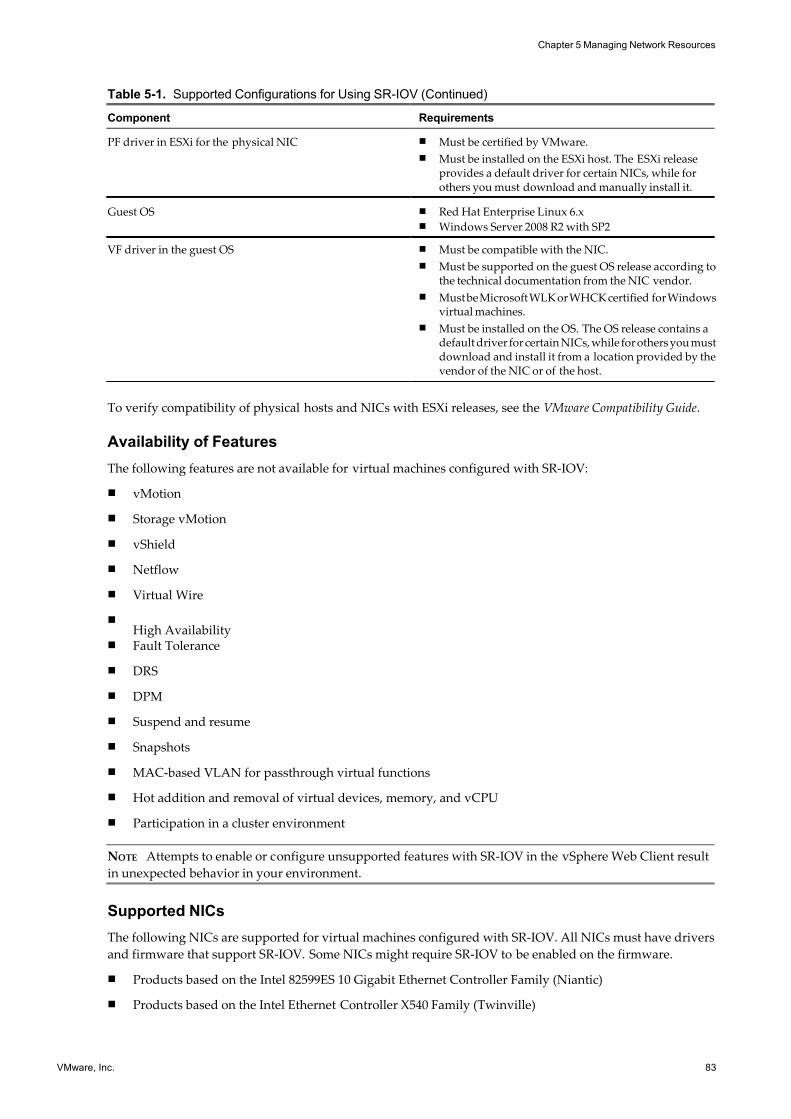
7/15/2019 Vsphere Esxi Vcenter Server 51 Networking Guide
http://slidepdf.com/reader/full/vsphere-esxi-vcenter-server-51-networking-guide-563280a1ebe2b 83/172
Table 5-1. Supported Configurations for Using SR-IOV (Continued)
Component Requirements
PF driver in ESXi for the physical NIC n Must be certified by VMware.
n Must be installed on the ESXi host. The ESXi releaseprovides a default driver for certain NICs, while forothers you must download and manually install it.
Guest OS n Red Hat Enterprise Linux 6.xn Windows Server 2008 R2 with SP2
VF driver in the guest OS n Must be compatible with the NIC.
n Must be supported on the guest OS release according tothe technical documentation from the NIC vendor.
n Must be Microsoft WLK or WHCK certified for Windowsvirtual machines.
n Must be installed on the OS. The OS release contains adefault driver for certain NICs, while for others you mustdownload and install it from a location provided by thevendor of the NIC or of the host.
To verify compatibility of physical hosts and NICs with ESXi releases, see the VMware Compatibility Guide.
Availability of Features
The following features are not available for virtual machines configured with SR-IOV:
n vMotion
n Storage vMotion
n vShield
n Netflow
n Virtual Wire
nHigh Availability
n Fault Tolerance
n DRS
n DPM
n Suspend and resume
n Snapshots
n MAC-based VLAN for passthrough virtual functions
n Hot addition and removal of virtual devices, memory, and vCPU
n Participation in a cluster environment
NOTE Attempts to enable or configure unsupported features with SR-IOV in the vSphere Web Client result
in unexpected behavior in your environment.
Supported NICs
The following NICs are supported for virtual machines configured with SR-IOV. All NICs must have drivers
and firmware that support SR-IOV. Some NICs might require SR-IOV to be enabled on the firmware.
n Products based on the Intel 82599ES 10 Gigabit Ethernet Controller Family (Niantic)
n Products based on the Intel Ethernet Controller X540 Family (Twinville)
Chapter 5 Managing Network Resources
VMware, Inc. 83
7/15/2019 Vsphere Esxi Vcenter Server 51 Networking Guide
http://slidepdf.com/reader/full/vsphere-esxi-vcenter-server-51-networking-guide-563280a1ebe2b 84/172
n Emulex OneConnect (BE3)
Upgrading from earlier versions of vSphere
If you upgrade from vSphere 5.0 or earlier to vSphere 5.1 or later, SR-IOV support is not available until you
update the NIC drivers for the vSphere release. NICs must have firmware and drivers that support SR-IOV
enabled for SR-IOV functionality to operate.
vSphere 5.1 and Virtual Function Interaction
Virtual functions (VFs) are lightweight PCIe functions that contain all the resources necessary for data
movement but have a carefully minimized set of configuration resources. There are some restrictions in the
interactions between vSphere 5.1 and VFs.
n When a physical NIC creates VFs for SR-IOV to use, the physical NIC becomes a hidden uplink and cannot
be used as a normal uplink. This means it cannot be added to a standard or distributed switch.
n There is no rate control for VFs in vSphere 5.1. Every VF could potentially use the entire bandwidth for a
physical link.
n When a VF device is configured as a passthrough device on a virtual machine, the standby and hibernate
functions for the virtual machine are not supported.
n Due to the limited number of vectors available for passthrough devices, there is a limited number of VFs
supported on an vSphere ESXi host . vSphere 5.1 SR-IOV supports up to 41 VFs on supported Intel NICs
and up to 64 VFs on supported Emulex NICs.
The actual number of VFs supported depends on your system configuration. For example, if you have
both Intel and Emulex NICs present with SR-IOV enabled, the number of VFs available for the Intel NICs
depends on how many VFs are configured for the Emulex NIC, and the reverse. You can use the following
formula to roughly estimated the number of VFs available for use:
3X + 2Y < 128
Where X is the number of Intel VFs, and Y is the number of Emulex VFs.
n If a supported Intel NIC loses connection, all VFs from the same physical NIC stop communication,including between VFs.
n If a supported Emulex NIC loses connection, all VFs stop communication with the external environment,
but VF communication still functions.
n VF drivers offer many different features, such as IPv6 support, TSO, and LRO Checksum. See your
vendor’s documentation for further details.
DirectPath I/O vs SR-IOV
SR-IOV offers performance benefits and tradeoffs similar to those of DirectPath I/O. DirectPath I/O and SR-
IOV have similar functionalty but you use them to accomplish different things.
SR-IOV is beneficial in workloads with very high packet rates or very low latency requirements. Like DirectPathI/O, SR-IOV is not compatible with certain core virtualization features, such as vMotion. SR-IOV does, however,
allow for a single physical device to be shared amongst multiple guests.
With DirectPath I/O you can map only one physical funtion to one virtual machine. SR-IOV lets you share a
single physical device, allowing multiple virtual machines to connect directly to the physical funtion.
This functionality allows you to virtualize low-latency (less than 50 microsec) and high PPS (greater than 50,000
such as network appliances or purpose built solutions) workloads on a VMWorkstation.
vSphere Networking
84 VMware, Inc.
7/15/2019 Vsphere Esxi Vcenter Server 51 Networking Guide
http://slidepdf.com/reader/full/vsphere-esxi-vcenter-server-51-networking-guide-563280a1ebe2b 85/172
Configure a Virtual Machine to Use SR-IOV in the vSphere Web Client
To use the capabilities of SR-IOV, you must enable the SR-IOV virtual functions on the host and connect a
virtual machine to the functions.
Procedure
1 Configure SR-IOV in a Host Profile with the vSphere Web Client on page 85
Before you can connect a virtual machine to a virtual function, you have to configure the virtual functions
of the physical NIC on your host by using a host profile.
2 Assign a Virtual Function to a Virtual Machine in the vSphere Web Client on page 86
To ensure that a virtual machine and a physical NIC can exchange data, you must associate a virtual
machine with one or more virtual functions.
Configure SR-IOV in a Host Profile with the vSphere Web Client
Before you can connect a virtual machine to a virtual function, you have to configure the virtual functions of
the physical NIC on your host by using a host profile.
You can enable SR-IOV virtual functions on the host by using the esxcli system module parameters set vCLI
command on the NIC driver parameter for virtual functions in accordance with the driver documentation. For
more information about using vCLI commands, see vSphere Command-Line Interface Documentation.
Prerequisites
n Verify that the configuration of your environment supports SR-IOV. See “SR-IOV Support,” on page 82.
n Create a host profile using the SR-IOV capable host as a reference. For more information about host
profiles, see the vSphere Host Profiles documentation.
Procedure
1 From the vSphere Web Client Home, click Rules and Profiles > Host Profiles.
2 Select the host profile from the list and click the Manage tab.
3 Click Edit Host Profile and expand the General System Settings folder.
4 Expand Kernel Module Parameter and select the parameter of the physical function driver for creating
virtual functions.
For example, the parameter for the physical function driver of an Intel physical NIC is max_vfs.
5 In the Value text box, type a comma-separated list of valid virtual function numbers.
Each list entry is the number of virtual functions that you want to configure for each physical function. A
value of 0 means SR-IOV will not be enabled for that physical function.
For example, if you have a dual port, set the value to
x,y
where x or y is the number of virtual functions you want to enable for a single port.
If the target number of virtual functions on a single host is 30, you might have two dual port cards set to
0,10,10,10.
NOTE The number of virtual functions supported and available for configuration depends on your system
configuration.
6 Click Finish.
7 Remediate the modified host profile to the target host.
Chapter 5 Managing Network Resources
VMware, Inc. 85
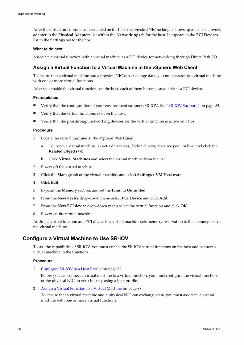
7/15/2019 Vsphere Esxi Vcenter Server 51 Networking Guide
http://slidepdf.com/reader/full/vsphere-esxi-vcenter-server-51-networking-guide-563280a1ebe2b 86/172
After the virtual functions become enabled on the host, the physical NIC no longer shows up as a host network
adapter in the Physical Adapters list within the Networking tab for the host. It appears in the PCI Devices
list in the Settings tab for the host.
What to do next
Associate a virtual function with a virtual machine as a PCI device for networking through Direct Path I/O.
Assign a Virtual Function to a Virtual Machine in the vSphere Web Client
To ensure that a virtual machine and a physical NIC can exchange data, you must associate a virtual machine
with one or more virtual functions.
After you enable the virtual functions on the host, each of them becomes available as a PCI device.
Prerequisites
n Verify that the configuration of your environment supports SR-IOV. See “SR-IOV Support,” on page 82.
n Verify that the virtual functions exist on the host.
n Verify that the passthrough networking devices for the virtual function is active on a host.
Procedure
1 Locate the virtual machine in the vSphere Web Client.
a To locate a virtual machine, select a datacenter, folder, cluster, resource pool, or host and click the
Related Objects tab.
b Click Virtual Machines and select the virtual machine from the list.
2 Power off the virtual machine.
3 Click the Manage tab of the virtual machine, and select Settings > VM Hardware.
4 Click Edit.
5 Expand the Memory section, and set the Limit to Unlimited.
6 From the New device drop-down menu select PCI Device and click Add.
7 From the New PCI device drop-down menu select the virtual function and click OK.
8 Power on the virtual machine.
Adding a virtual function as a PCI device to a virtual machine sets memory reservation to the memory size of
the virtual machine.
Configure a Virtual Machine to Use SR-IOV
To use the capabilities of SR-IOV, you must enable the SR-IOV virtual functions on the host and connect a
virtual machine to the functions.
Procedure
1 Configure SR-IOV in a Host Profile on page 87
Before you can connect a virtual machine to a virtual function, you must configure the virtual functions
of the physical NIC on your host by using a host profile.
2 Assign a Virtual Function to a Virtual Machine on page 88
To ensure that a virtual machine and a physical NIC can exchange data, you must associate a virtual
machine with one or more virtual functions.
vSphere Networking
86 VMware, Inc.
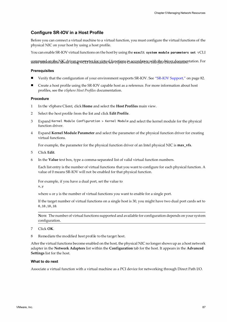
7/15/2019 Vsphere Esxi Vcenter Server 51 Networking Guide
http://slidepdf.com/reader/full/vsphere-esxi-vcenter-server-51-networking-guide-563280a1ebe2b 87/172
Configure SR-IOV in a Host Profile
Before you can connect a virtual machine to a virtual function, you must configure the virtual functions of the
physical NIC on your host by using a host profile.
You can enable SR-IOV virtual functions on the host by using the esxcli system module parameters set vCLI
command on the NIC driver parameter for virtual functions in accordance with the driver documentation. Formore information about using vCLI commands, see vSphere Command-Line Interface Documentation.
Prerequisites
n Verify that the configuration of your environment supports SR-IOV. See “SR-IOV Support,” on page 82.
n Create a host profile using the SR-IOV capable host as a reference. For more information about host
profiles, see the vSphere Host Profiles documentation.
Procedure
1 In the vSphere Client, click Home and select the Host Profiles main view.
2 Select the host profile from the list and click Edit Profile.
3 Expand Kernel Module Configuration > Kernel Module and select the kernel module for the physicalfunction driver.
4 Expand Kernel Module Parameter and select the parameter of the physical function driver for creating
virtual functions.
For example, the parameter for the physical function driver of an Intel physical NIC is max_vfs.
5 Click Edit.
6 In the Value text box, type a comma-separated list of valid virtual function numbers.
Each list entry is the number of virtual functions that you want to configure for each physical function. A
value of 0 means SR-IOV will not be enabled for that physical function.
For example, if you have a dual port, set the value to
x,y
where x or y is the number of virtual functions you want to enable for a single port.
If the target number of virtual functions on a single host is 30, you might have two dual port cards set to
0,10,10,10.
NOTE The number of virtual functions supported and available for configuration depends on your system
configuration.
7 Click OK.
8 Remediate the modified host profile to the target host.
After the virtual functions become enabled on the host, the physical NIC no longer shows up as a host network
adapter in the Network Adapters list within the Configuration tab for the host. It appears in the Advanced
Settings list for the host.
What to do next
Associate a virtual function with a virtual machine as a PCI device for networking through Direct Path I/O.
Chapter 5 Managing Network Resources
VMware, Inc. 87
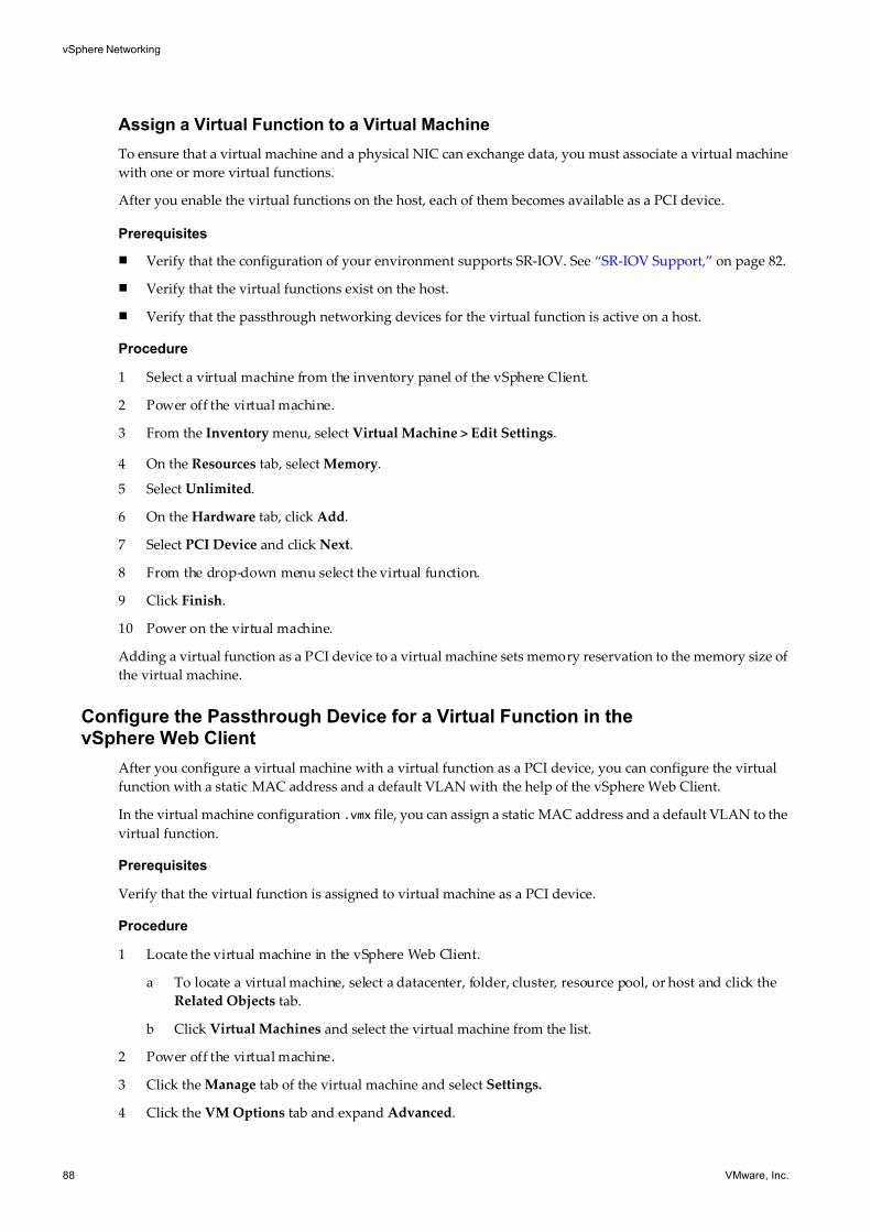
7/15/2019 Vsphere Esxi Vcenter Server 51 Networking Guide
http://slidepdf.com/reader/full/vsphere-esxi-vcenter-server-51-networking-guide-563280a1ebe2b 88/172
Assign a Virtual Function to a Virtual Machine
To ensure that a virtual machine and a physical NIC can exchange data, you must associate a virtual machine
with one or more virtual functions.
After you enable the virtual functions on the host, each of them becomes available as a PCI device.
Prerequisites
n Verify that the configuration of your environment supports SR-IOV. See “SR-IOV Support,” on page 82.
n Verify that the virtual functions exist on the host.
n Verify that the passthrough networking devices for the virtual function is active on a host.
Procedure
1 Select a virtual machine from the inventory panel of the vSphere Client.
2 Power off the virtual machine.
3 From the Inventory menu, select Virtual Machine > Edit Settings.
4 On the Resources tab, select Memory.
5 Select Unlimited.
6 On the Hardware tab, click Add.
7 Select PCI Device and click Next.
8 From the drop-down menu select the virtual function.
9 Click Finish.
10 Power on the virtual machine.
Adding a virtual function as a PCI device to a virtual machine sets memory reservation to the memory size of
the virtual machine.
Configure the Passthrough Device for a Virtual Function in thevSphere Web Client
After you configure a virtual machine with a virtual function as a PCI device, you can configure the virtual
function with a static MAC address and a default VLAN with the help of the vSphere Web Client.
In the virtual machine configuration .vmx file, you can assign a static MAC address and a default VLAN to the
virtual function.
Prerequisites
Verify that the virtual function is assigned to virtual machine as a PCI device.
Procedure
1 Locate the virtual machine in the vSphere Web Client.
a To locate a virtual machine, select a datacenter, folder, cluster, resource pool, or host and click the
Related Objects tab.
b Click Virtual Machines and select the virtual machine from the list.
2 Power off the virtual machine.
3 Click the Manage tab of the virtual machine and select Settings.
4 Click the VM Options tab and expand Advanced.
vSphere Networking
88 VMware, Inc.
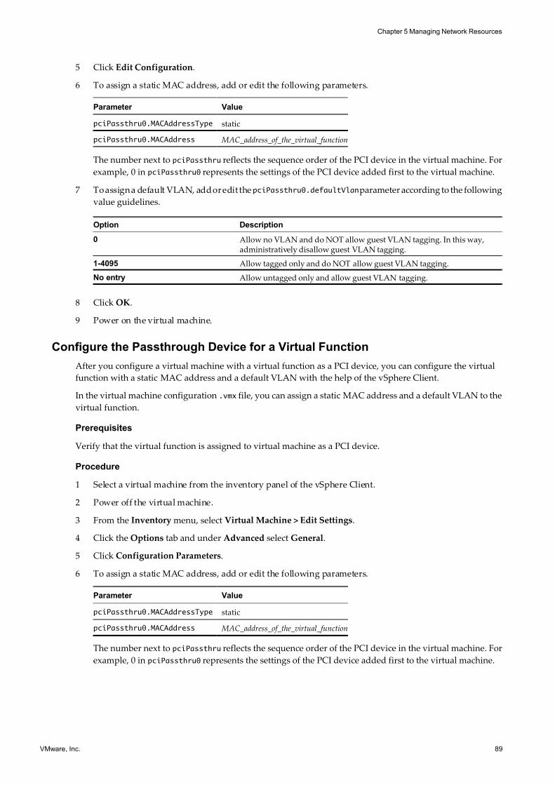
7/15/2019 Vsphere Esxi Vcenter Server 51 Networking Guide
http://slidepdf.com/reader/full/vsphere-esxi-vcenter-server-51-networking-guide-563280a1ebe2b 89/172
5 Click Edit Configuration.
6 To assign a static MAC address, add or edit the following parameters.
Parameter Value
pciPassthru0.MACAddressType static
pciPassthru0.MACAddress MAC_address_of_the_virtual_function
The number next to pciPassthru reflects the sequence order of the PCI device in the virtual machine. For
example, 0 in pciPassthru0 represents the settings of the PCI device added first to the virtual machine.
7 To assign a default VLAN, add or edit the pciPassthru0.defaultVlanparameter according to the following
value guidelines.
Option Description
0 Allow no VLAN and do NOT allow guest VLAN tagging. In this way,administratively disallow guest VLAN tagging.
1-4095 Allow tagged only and do NOT allow guest VLAN tagging.
No entry Allow untagged only and allow guest VLAN tagging.
8 Click OK.
9 Power on the virtual machine.
Configure the Passthrough Device for a Virtual Function
After you configure a virtual machine with a virtual function as a PCI device, you can configure the virtual
function with a static MAC address and a default VLAN with the help of the vSphere Client.
In the virtual machine configuration .vmx file, you can assign a static MAC address and a default VLAN to the
virtual function.
Prerequisites
Verify that the virtual function is assigned to virtual machine as a PCI device.
Procedure
1 Select a virtual machine from the inventory panel of the vSphere Client.
2 Power off the virtual machine.
3 From the Inventory menu, select Virtual Machine > Edit Settings.
4 Click the Options tab and under Advanced select General.
5 Click Configuration Parameters.
6 To assign a static MAC address, add or edit the following parameters.
Parameter Value
pciPassthru0.MACAddressType static
pciPassthru0.MACAddress MAC_address_of_the_virtual_function
The number next to pciPassthru reflects the sequence order of the PCI device in the virtual machine. For
example, 0 in pciPassthru0 represents the settings of the PCI device added first to the virtual machine.
Chapter 5 Managing Network Resources
VMware, Inc. 89

7/15/2019 Vsphere Esxi Vcenter Server 51 Networking Guide
http://slidepdf.com/reader/full/vsphere-esxi-vcenter-server-51-networking-guide-563280a1ebe2b 90/172
7 To assign a default VLAN, add or edit the pciPassthru0.defaultVlanparameter according to the following
value guidelines.
Option Description
0 Allow no VLAN and do NOT allow guest VLAN tagging. In this way,administratively disallow guest VLAN tagging.
1-4095Allow tagged only and do NOT allow guest VLAN tagging.
No entry Allow untagged only and allow guest VLAN tagging.
8 Click OK.
9 Power on the virtual machine.
vSphere Networking
90 VMware, Inc.
7/15/2019 Vsphere Esxi Vcenter Server 51 Networking Guide
http://slidepdf.com/reader/full/vsphere-esxi-vcenter-server-51-networking-guide-563280a1ebe2b 91/172
Networking Policies 6Policies set at the standard switch or distributed port group level apply to all of the port groups on the standard
switch or to ports in the distributed port group. The exceptions are the configuration options that are
overridden at the standard port group or distributed port level.
This chapter includes the following topics:
n “Load Balancing and Failover Policy,” on page 91
n “VLAN Policy,” on page 105
n “Security Policy,” on page 108
n “Traffic Shaping Policy,” on page 114
n “Resource Allocation Policy,” on page 121
n “Monitoring Policy,” on page 123
n “Port Blocking Policies,” on page 125
n “Manage Policies for Multiple Port Groups on a vSphere Distributed Switch,” on page 126
n “Manage Policies for Multiple Port Groups on a vSphere Distributed Switch in the vSphere Web
Client,” on page 129
Load Balancing and Failover Policy
Load balancing and failover policies allow you to determine how network traffic is distributed between
adapters and how to re-route traffic in the event of adapter failure.
You can edit your load balancing and failover policy by configuring the following parameters:
n Load Balancing policy determines how outgoing traffic is distributed among the network adapters
associated with a switch or port group.
NOTE Incoming traffic is controlled by the load balancing policy on the physical switch.
n Failover Detection controls the link status and beacon probing. Beaconing is not supported with guest
VLAN tagging.
n Network Adapter Order can be active or standby.
VMware, Inc. 91
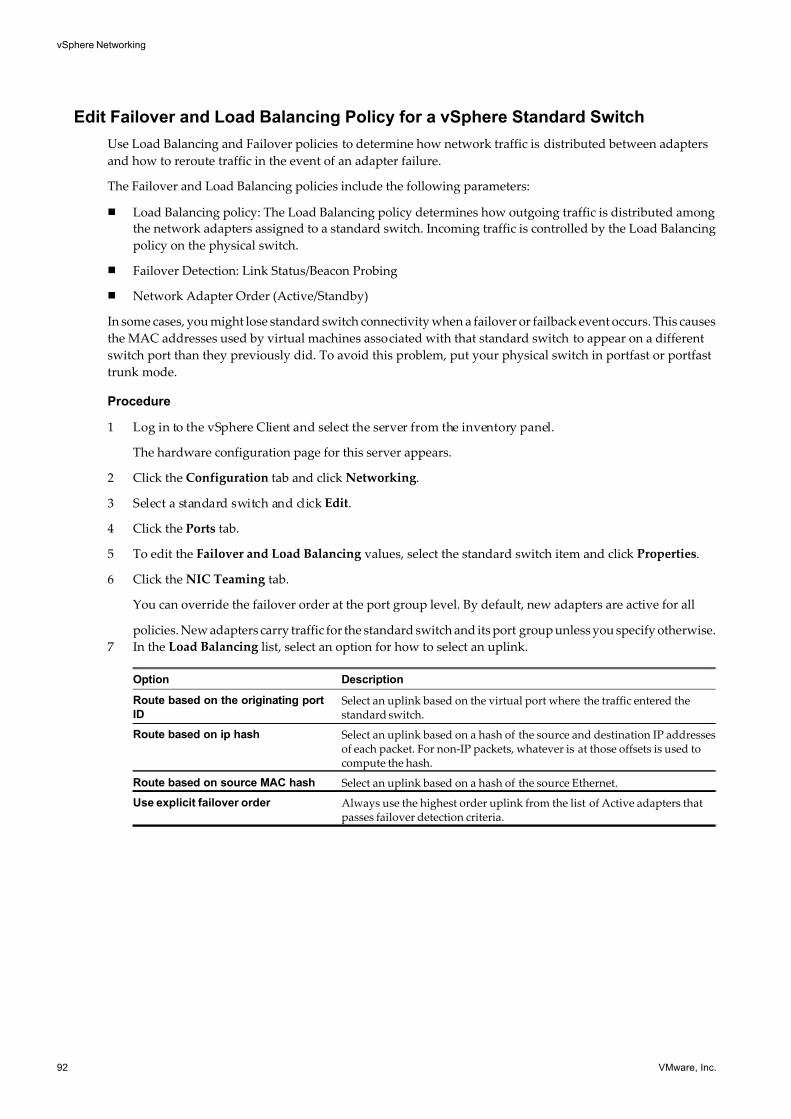
7/15/2019 Vsphere Esxi Vcenter Server 51 Networking Guide
http://slidepdf.com/reader/full/vsphere-esxi-vcenter-server-51-networking-guide-563280a1ebe2b 92/172
Edit Failover and Load Balancing Policy for a vSphere Standard Switch
Use Load Balancing and Failover policies to determine how network traffic is distributed between adapters
and how to reroute traffic in the event of an adapter failure.
The Failover and Load Balancing policies include the following parameters:
n Load Balancing policy: The Load Balancing policy determines how outgoing traffic is distributed among
the network adapters assigned to a standard switch. Incoming traffic is controlled by the Load Balancing
policy on the physical switch.
n Failover Detection: Link Status/Beacon Probing
n Network Adapter Order (Active/Standby)
In some cases, you might lose standard switch connectivity when a failover or failback event occurs. This causes
the MAC addresses used by virtual machines associated with that standard switch to appear on a different
switch port than they previously did. To avoid this problem, put your physical switch in portfast or portfast
trunk mode.
Procedure
1 Log in to the vSphere Client and select the server from the inventory panel.
The hardware configuration page for this server appears.
2 Click the Configuration tab and click Networking.
3 Select a standard switch and click Edit.
4 Click the Ports tab.
5 To edit the Failover and Load Balancing values, select the standard switch item and click Properties.
6 Click the NIC Teaming tab.
You can override the failover order at the port group level. By default, new adapters are active for all
policies. New adapters carry traffic for the standard switch and its port group unless you specify otherwise.
7 In the Load Balancing list, select an option for how to select an uplink.
Option Description
Route based on the originating port
ID
Select an uplink based on the virtual port where the traffic entered thestandard switch.
Route based on ip hash Select an uplink based on a hash of the source and destination IP addressesof each packet. For non-IP packets, whatever is at those offsets is used tocompute the hash.
Route based on source MAC hash Select an uplink based on a hash of the source Ethernet.
Use explicit failover order Always use the highest order uplink from the list of Active adapters thatpasses failover detection criteria.
vSphere Networking
92 VMware, Inc.
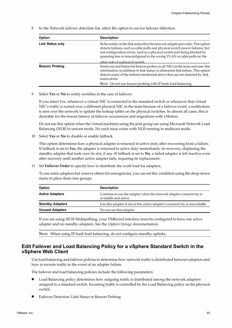
7/15/2019 Vsphere Esxi Vcenter Server 51 Networking Guide
http://slidepdf.com/reader/full/vsphere-esxi-vcenter-server-51-networking-guide-563280a1ebe2b 93/172
8 In the Network failover detection list, select the option to use for failover detection.
Option Description
Link Status only Relies solely on the link status that the network adapter provides. This optiondetects failures, such as cable pulls and physical switch power failures, butnot configuration errors, such as a physical switch port being blocked byspanning tree or misconfigured to the wrong VLAN or cable pulls on the
other side of a physical switch.Beacon Probing Sends out and listens for beacon probes on all NICs in the team and uses this
information, in addition to link status, to determine link failure. This optiondetects many of the failures mentioned above that are not detected by linkstatus alone.
NOTE Do not use beacon probing with IP-hash load balancing.
9 Select Yes or No to notify switches in the case of failover.
If you select Yes, whenever a virtual NIC is connected to the standard switch or whenever that virtual
NIC’s traffic is routed over a different physical NIC in the team because of a failover event, a notification
is sent over the network to update the lookup tables on the physical switches. In almost all cases, this is
desirable for the lowest latency of failover occurrences and migrations with vMotion.
Do not use this option when the virtual machines using the port group are using Microsoft Network Load
Balancing (NLB) in unicast mode. No such issue exists with NLB running in multicast mode.
10 Select Yes or No to disable or enable failback.
This option determines how a physical adapter is returned to active duty after recovering from a failure.
If failback is set to Yes , the adapter is returned to active duty immediately on recovery, displacing the
standby adapter that took over its slot, if any. If failback is set to No , a failed adapter is left inactive even
after recovery until another active adapter fails, requiring its replacement.
11 Set Failover Order to specify how to distribute the work load for adapters.
To use some adapters but reserve others for emergencies, you can set this condition using the drop-down
menu to place them into groups.
Option Description
Active Adapters Continue to use the adapter when the network adapter connectivity isavailable and active.
Standby Adapters Use this adapter if one of the active adapter’s connectivity is unavailable.
Unused Adapters Do not use this adapter.
If you are using iSCSI Multipathing, your VMkernel interface must be configured to have one active
adapter and no standby adapters. See the vSphere Storage documentation.
NOTE When using IP-hash load balancing, do not configure standby uplinks.
Edit Failover and Load Balancing Policy for a vSphere Standard Switch in thevSphere Web Client
Use load balancing and failover policies to determine how network traffic is distributed between adapters and
how to reroute traffic in the event of an adapter failure.
The failover and load balancing policies include the following parameters:
n Load Balancing policy determines how outgoing traffic is distributed among the network adapters
assigned to a standard switch. Incoming traffic is controlled by the Load Balancing policy on the physical
switch.
n Failover Detection: Link Status or Beacon Probing
Chapter 6 Networking Policies
VMware, Inc. 93
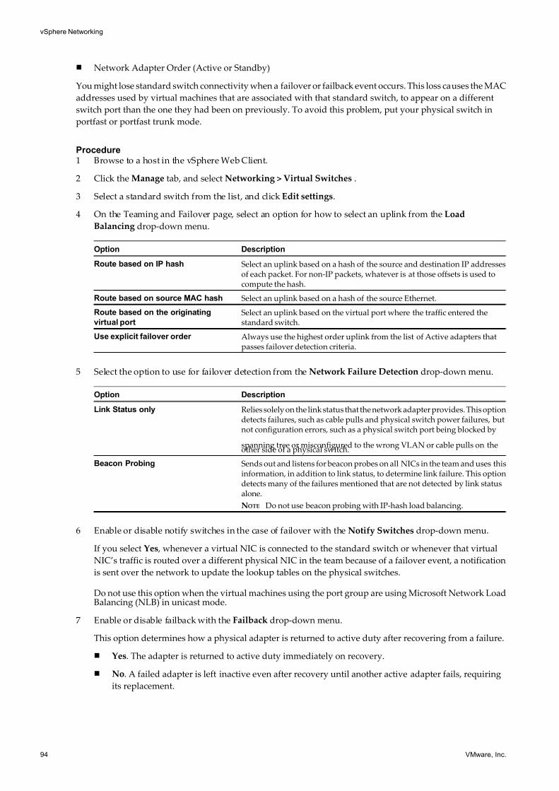
7/15/2019 Vsphere Esxi Vcenter Server 51 Networking Guide
http://slidepdf.com/reader/full/vsphere-esxi-vcenter-server-51-networking-guide-563280a1ebe2b 94/172
n Network Adapter Order (Active or Standby)
You might lose standard switch connectivity when a failover or failback event occurs. This loss causes the MAC
addresses used by virtual machines that are associated with that standard switch, to appear on a different
switch port than the one they had been on previously. To avoid this problem, put your physical switch in
portfast or portfast trunk mode.
Procedure1 Browse to a host in the vSphere Web Client.
2 Click the Manage tab, and select Networking > Virtual Switches .
3 Select a standard switch from the list, and click Edit settings.
4 On the Teaming and Failover page, select an option for how to select an uplink from the Load
Balancing drop-down menu.
Option Description
Route based on IP hash Select an uplink based on a hash of the source and destination IP addressesof each packet. For non-IP packets, whatever is at those offsets is used tocompute the hash.
Route based on source MAC hash Select an uplink based on a hash of the source Ethernet.
Route based on the originating
virtual port
Select an uplink based on the virtual port where the traffic entered thestandard switch.
Use explicit failover order Always use the highest order uplink from the list of Active adapters thatpasses failover detection criteria.
5 Select the option to use for failover detection from the Network Failure Detection drop-down menu.
Option Description
Link Status only Relies solely on the link status that the network adapter provides. This optiondetects failures, such as cable pulls and physical switch power failures, butnot configuration errors, such as a physical switch port being blocked by
spanning tree or misconfigured to the wrong VLAN or cable pulls on theother side of a physical switch.
Beacon Probing Sends out and listens for beacon probes on all NICs in the team and uses thisinformation, in addition to link status, to determine link failure. This optiondetects many of the failures mentioned that are not detected by link statusalone.
NOTE Do not use beacon probing with IP-hash load balancing.
6 Enable or disable notify switches in the case of failover with the Notify Switches drop-down menu.
If you select Yes , whenever a virtual NIC is connected to the standard switch or whenever that virtual
NIC’s traffic is routed over a different physical NIC in the team because of a failover event, a notification
is sent over the network to update the lookup tables on the physical switches.
Do not use this option when the virtual machines using the port group are using Microsoft Network LoadBalancing (NLB) in unicast mode.
7 Enable or disable failback with the Failback drop-down menu.
This option determines how a physical adapter is returned to active duty after recovering from a failure.
n Yes. The adapter is returned to active duty immediately on recovery.
n No. A failed adapter is left inactive even after recovery until another active adapter fails, requiring
its replacement.
vSphere Networking
94 VMware, Inc.
7/15/2019 Vsphere Esxi Vcenter Server 51 Networking Guide
http://slidepdf.com/reader/full/vsphere-esxi-vcenter-server-51-networking-guide-563280a1ebe2b 95/172
8 Set the Failover Order to specify how to distribute the work load for adapters.
Select an adapter and use the up and down arrows to position it in the appropriate adapter category.
Option Description
Active Adapters Continue to use the adapter when the network adapter connectivity isavailable and active.
Standby Adapters Use this adapter if one of the active adapter’s connectivity is unavailable.
Unused Adapters Do not use this adapter.
If you are using iSCSI Multipathing, configure your VMkernel interface to have one active adapter and
no standby adapters. See the vSphere Storage documentation.
NOTE When using IP-hash load balancing, do not configure standby uplinks.
9 Click OK.
Edit the Failover and Load Balancing Policy on a Standard Port Group
Failover and load balancing policies allow you to determine how network traffic is distributed between
adapters and how to re-route traffic in the event of an adapter failure.
Procedure
1 Log in to the vSphere Client and select the host from the inventory panel.
2 Click the Configuration tab and click Networking.
3 Select a port group and click Edit.
4 In the Properties dialog box, click the Ports tab.
5 To edit the Failover and Load Balancing values for the port group, select the port group and click
Properties.
6 Click the NIC Teaming tab.You can override the failover order at the port-group level. By default, new adapters are active for all
policies. New adapters carry traffic for the standard switch and its port group unless you specify otherwise.
Chapter 6 Networking Policies
VMware, Inc. 95
7/15/2019 Vsphere Esxi Vcenter Server 51 Networking Guide
http://slidepdf.com/reader/full/vsphere-esxi-vcenter-server-51-networking-guide-563280a1ebe2b 96/172
7 Specify the settings in the Policy Exceptions group.
Option Description
Load Balancing Specify how to choose an uplink.
n Route based on the originating port ID. Choose an uplink based on thevirtual port where the traffic entered the virtual switch.
n Route based on ip hash. Choose an uplink based on a hash of the sourceand destination IP addresses of each packet. For non-IP packets,whatever is at those offsets is used to compute the hash.
n Route based on source MAC hash. Choose an uplink based on a hashof the source Ethernet.
n Use explicit failover order. Always use the highest order uplink fromthe list of Active adapters which passes failover detection criteria.
NOTE IP-based teaming requires that the physical switch be configured withetherchannel. For all other options, etherchannel should be disabled.
Network Failover Detection Specify the method to use for failover detection.
n Link Status only. Relies solely on the link status that the network adapterprovides. This option detects failures, such as cable pulls and physicalswitch power failures, but not configuration errors, such as a physicalswitch port being blocked by spanning tree or that is misconfigured to
the wrong VLAN or cable pulls on the other side of a physical switch.n Beacon Probing. Sends out and listens for beacon probes on all NICs in
the team and uses this information, in addition to link status, todetermine link failure. This detects many of the failures previouslymentioned that are not detected by link status alone.
Notify Switches Select Yes or No to notify switches in the case of failover.
If you select Yes , whenever a virtual NIC is connected to the standard switchor whenever that virtual NIC’s traffic would be routed over a differentphysical NIC in the team because of a failover event, a notification is sent outover the network to update the lookup tables on physical switches. In almostall cases, this process is desirable for the lowest latency of failoveroccurrences and migrations with vMotion.
NOTE Do not use this option when the virtual machines using the port groupare using Microsoft Network Load Balancing in unicast mode. No such issue
exists with NLB running in multicast mode.Failback Select Yes or No to disable or enable failback.
This option determines how a physical adapter is returned to active dutyafter recovering from a failure. If failback is set to Yes (default), the adapteris returned to active duty immediately upon recovery, displacing the standbyadapter that took over its slot, if any. If failback is set to No , a failed adapteris left inactive even after recovery until another currently active adapter fails,requiring its replacement.
Failover Order Specify how to distribute the work load for uplinks. If you want to use someuplinks but reserve others for emergencies in case the uplinks in use fail, setthis condition by moving them into different groups:
n Active Uplinks. Continue to use the uplink when the network adapterconnectivity is up and active.
n
Standby Uplinks. Use this uplink if one of the active adapter’sconnectivity is down.
n Unused Uplinks. Do not use this uplink.
8 Click OK.
vSphere Networking
96 VMware, Inc.
7/15/2019 Vsphere Esxi Vcenter Server 51 Networking Guide
http://slidepdf.com/reader/full/vsphere-esxi-vcenter-server-51-networking-guide-563280a1ebe2b 97/172
Edit the Failover and Load Balancing Policy on a Standard Port Group in thevSphere Web Client
Failover and load balancing policies lets you determine how network traffic is distributed between adapters
and how to reroute traffic in the event of an adapter failure.
Procedure
1 Browse to a host in the vSphere Web Client.
2 Click the Manage tab, and click Networking > Virtual Switches.
3 Select a standard switch from the list.
A detailed schematic of the standard switch appears.
4 Click Edit settings.
5 On the Teaming and Failover page, select the check boxes next to the teaming and failover policies that
you want to edit at the standard port group level.
Option DescriptionLoad Balancing Specify how to choose an uplink.
n Route based on the originating virtual port. Choose an uplink based onthe virtual port where the traffic entered the virtual switch.
n Route based on IP hash. Choose an uplink based on a hash of the sourceand destination IP addresses of each packet. For non-IP packets,whatever is at those offsets is used to compute the hash.
n Route based on source MAC hash. Choose an uplink based on a hashof the source Ethernet.
n Use explicit failover order. Always use the highest order uplink fromthe list of Active adapters which passes failover detection criteria.
NOTE IP-based teaming requires that the physical switch be configured withetherchannel. For all other options, etherchannel should be disabled.
Network Failover Detection Specify the method to use for failover detection.n Link Status only. Relies solely on the link status that the network adapter
provides. This option detects failures, such as cable pulls and physicalswitch power failures, but not configuration errors, such as a physicalswitch port being blocked by spanning tree or that is misconfigured tothe wrong VLAN or cable pulls on the other side of a physical switch.
n Beacon Probing. Sends out and listens for beacon probes on all NICs inthe team and uses this information, in addition to link status, todetermine link failure. This detects many of the failures previouslymentioned that are not detected by link status alone.
Notify Switches Select Yes or No to notify switches in the case of failover.
If you select Yes , whenever a virtual NIC is connected to the standard switchor whenever that virtual NIC’s traffic is routed over a different physical NICin the team because of a failover event, a notification is sent over the network
to update the lookup tables on physical switches. In almost all cases, thisprocess is desirable for the lowest latency of failover occurrences andmigrations with vMotion.
NOTE Do not use this option when the virtual machines using the port groupare using Microsoft Network Load Balancing in unicast mode. No such issueexists with NLB running in multicast mode.
Chapter 6 Networking Policies
VMware, Inc. 97
7/15/2019 Vsphere Esxi Vcenter Server 51 Networking Guide
http://slidepdf.com/reader/full/vsphere-esxi-vcenter-server-51-networking-guide-563280a1ebe2b 98/172
Option Description
Failback Select Yes or No to disable or enable failback.
This option determines how a physical adapter is returned to active dutyafter recovering from a failure. If failback is set to Yes (default), the adapteris returned to active duty immediately upon recovery, displacing the standbyadapter that took over its slot, if any. If failback is set to No , a failed adapteris left inactive even after recovery until another currently active adapter fails,
requiring its replacement.Failover Order You can override the failover order at the port-group level. By default, new
adapters are active for all policies. New adapters carry traffic for the standardswitch and its port group unless you specify otherwise. Specify how todistribute the work load for uplinks. If you want to use some uplinks butreserve others for emergencies in case the uplinks in use fail, use the up anddown arrows to move them into different groups:
n Active adapters. Continue to use the uplink when the network adapterconnectivity is up and active.
n Standby adapters. Use this uplink if one of the active adapter’sconnectivity is down.
n Unused adapters. Do not use this uplink.
6 Click OK.
Edit the Teaming and Failover Policy on a Distributed Port Group
Teaming and Failover policies allow you to determine how network traffic is distributed between adapters
and how to re-route traffic in the event of an adapter failure.
Procedure
1 Log in to the vSphere Client and select the Networking inventory view.
2 Right-click the distributed port group in the inventory pane, and select Edit Settings.
3 Select Policies.
vSphere Networking
98 VMware, Inc.
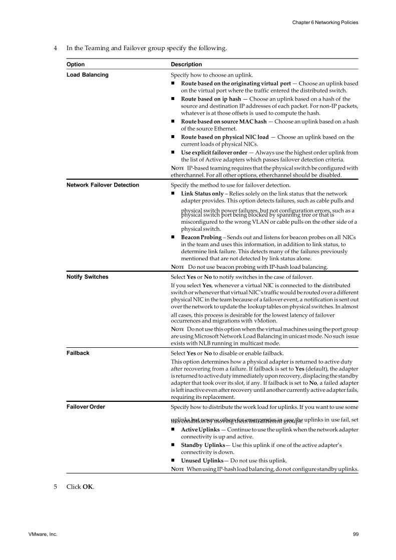
7/15/2019 Vsphere Esxi Vcenter Server 51 Networking Guide
http://slidepdf.com/reader/full/vsphere-esxi-vcenter-server-51-networking-guide-563280a1ebe2b 99/172
4 In the Teaming and Failover group specify the following.
Option Description
Load Balancing Specify how to choose an uplink.
n Route based on the originating virtual port — Choose an uplink basedon the virtual port where the traffic entered the distributed switch.
n Route based on ip hash — Choose an uplink based on a hash of thesource and destination IP addresses of each packet. For non-IP packets,whatever is at those offsets is used to compute the hash.
n Route based on source MAC hash — Choose an uplink based on a hashof the source Ethernet.
n Route based on physical NIC load — Choose an uplink based on thecurrent loads of physical NICs.
n Use explicit failover order — Always use the highest order uplink fromthe list of Active adapters which passes failover detection criteria.
NOTE IP-based teaming requires that the physical switch be configured withetherchannel. For all other options, etherchannel should be disabled.
Network Failover Detection Specify the method to use for failover detection.
n Link Status only – Relies solely on the link status that the networkadapter provides. This option detects failures, such as cable pulls and
physical switch power failures, but not configuration errors, such as aphysical switch port being blocked by spanning tree or that ismisconfigured to the wrong VLAN or cable pulls on the other side of aphysical switch.
n Beacon Probing – Sends out and listens for beacon probes on all NICsin the team and uses this information, in addition to link status, todetermine link failure. This detects many of the failures previouslymentioned that are not detected by link status alone.
NOTE Do not use beacon probing with IP-hash load balancing.
Notify Switches Select Yes or No to notify switches in the case of failover.
If you select Yes , whenever a virtual NIC is connected to the distributedswitch or whenever that virtual NIC’s traffic would be routed over a differentphysical NIC in the team because of a failover event, a notification is sent outover the network to update the lookup tables on physical switches. In almost
all cases, this process is desirable for the lowest latency of failoveroccurrences and migrations with vMotion.
NOTE Do not use this option when the virtual machines using the port groupare using Microsoft Network Load Balancing in unicast mode. No such issueexists with NLB running in multicast mode.
Failback Select Yes or No to disable or enable failback.
This option determines how a physical adapter is returned to active dutyafter recovering from a failure. If failback is set to Yes (default), the adapteris returned to active duty immediately upon recovery, displacing the standbyadapter that took over its slot, if any. If failback is set to No , a failed adapteris left inactive even after recovery until another currently active adapter fails,requiring its replacement.
Failover Order Specify how to distribute the work load for uplinks. If you want to use some
uplinks but reserve others for emergencies in case the uplinks in use fail, setthis condition by moving them into different groups:
n Active Uplinks — Continue to use the uplink when the network adapterconnectivity is up and active.
n Standby Uplinks— Use this uplink if one of the active adapter’sconnectivity is down.
n Unused Uplinks— Do not use this uplink.
NOTE When using IP-hash load balancing, do not configure standby uplinks.
5 Click OK.
Chapter 6 Networking Policies
VMware, Inc. 99
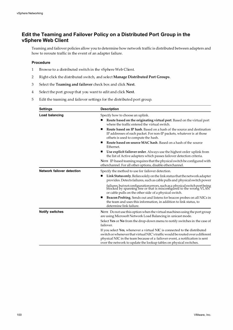
7/15/2019 Vsphere Esxi Vcenter Server 51 Networking Guide
http://slidepdf.com/reader/full/vsphere-esxi-vcenter-server-51-networking-guide-563280a1ebe2b 100/172
Edit the Teaming and Failover Policy on a Distributed Port Group in thevSphere Web Client
Teaming and failover policies allow you to determine how network traffic is distributed between adapters and
how to reroute traffic in the event of an adapter failure.
Procedure
1 Browse to a distributed switch in the vSphere Web Client.
2 Right-click the distributed switch, and select Manage Distributed Port Groups.
3 Select the Teaming and failover check box and click Next.
4 Select the port group that you want to edit and click Next.
5 Edit the teaming and failover settings for the distributed port group.
Settings Description
Load balancing Specify how to choose an uplink.
n Route based on the originating virtual port. Based on the virtual portwhere the traffic entered the virtual switch.
n Route based on IP hash. Based on a hash of the source and destinationIP addresses of each packet. For non-IP packets, whatever is at thoseoffsets is used to compute the hash.
n Route based on source MAC hash. Based on a hash of the sourceEthernet.
n Use explicit failover order. Always use the highest order uplink fromthe list of Active adapters which passes failover detection criteria.
NOTE IP-based teaming requires that the physical switch be configured withetherchannel. For all other options, disable etherchannel.
Network failover detection Specify the method to use for failover detection.
n Link Status only. Relies solely on the link status that the network adapterprovides. Detects failures, such as cable pulls and physical switch power
failures, but not configuration errors, such as a physical switch port being blocked by spanning tree or that is misconfigured to the wrong VLANor cable pulls on the other side of a physical switch.
n Beacon Probing. Sends out and listens for beacon probes on all NICs inthe team and uses this information, in addition to link status, todetermine link failure.
Notify switches NOTE Do not use this option when the virtual machines using the port groupare using Microsoft Network Load Balancing in unicast mode.
Select Yes or No from the drop-down menu to notify switches in the case offailover.
If you select Yes , whenever a virtual NIC is connected to the distributedswitch or whenever that virtual NIC’s traffic would be routed over a differentphysical NIC in the team because of a failover event, a notification is sentover the network to update the lookup tables on physical switches.
vSphere Networking
100 VMware, Inc.
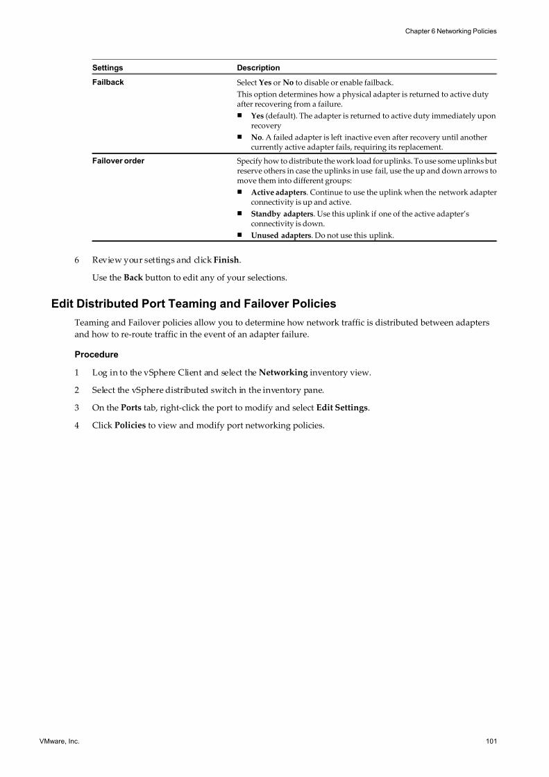
7/15/2019 Vsphere Esxi Vcenter Server 51 Networking Guide
http://slidepdf.com/reader/full/vsphere-esxi-vcenter-server-51-networking-guide-563280a1ebe2b 101/172
Settings Description
Failback Select Yes or No to disable or enable failback.
This option determines how a physical adapter is returned to active dutyafter recovering from a failure.
n Yes (default). The adapter is returned to active duty immediately uponrecovery
n No. A failed adapter is left inactive even after recovery until anothercurrently active adapter fails, requiring its replacement.
Failover order Specify how to distribute the work load for uplinks. To use some uplinks butreserve others in case the uplinks in use fail, use the up and down arrows tomove them into different groups:
n Active adapters. Continue to use the uplink when the network adapterconnectivity is up and active.
n Standby adapters. Use this uplink if one of the active adapter’sconnectivity is down.
n Unused adapters. Do not use this uplink.
6 Review your settings and click Finish.
Use the Back button to edit any of your selections.
Edit Distributed Port Teaming and Failover Policies
Teaming and Failover policies allow you to determine how network traffic is distributed between adapters
and how to re-route traffic in the event of an adapter failure.
Procedure
1 Log in to the vSphere Client and select the Networking inventory view.
2 Select the vSphere distributed switch in the inventory pane.
3 On the Ports tab, right-click the port to modify and select Edit Settings.
4 Click Policies to view and modify port networking policies.
Chapter 6 Networking Policies
VMware, Inc. 101
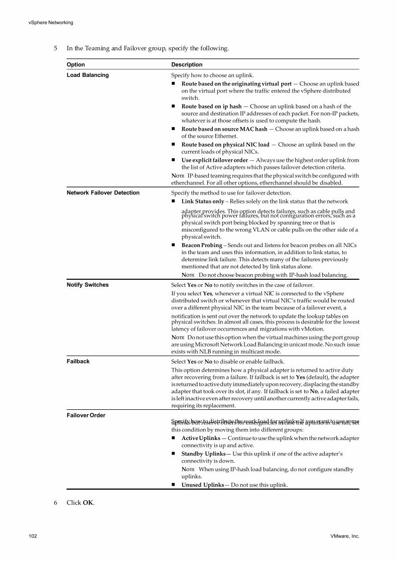
7/15/2019 Vsphere Esxi Vcenter Server 51 Networking Guide
http://slidepdf.com/reader/full/vsphere-esxi-vcenter-server-51-networking-guide-563280a1ebe2b 102/172
5 In the Teaming and Failover group, specify the following.
Option Description
Load Balancing Specify how to choose an uplink.
n Route based on the originating virtual port — Choose an uplink basedon the virtual port where the traffic entered the vSphere distributedswitch.
n Route based on ip hash — Choose an uplink based on a hash of thesource and destination IP addresses of each packet. For non-IP packets,whatever is at those offsets is used to compute the hash.
n Route based on source MAC hash — Choose an uplink based on a hashof the source Ethernet.
n Route based on physical NIC load — Choose an uplink based on thecurrent loads of physical NICs.
n Use explicit failover order — Always use the highest order uplink fromthe list of Active adapters which passes failover detection criteria.
NOTE IP-based teaming requires that the physical switch be configured withetherchannel. For all other options, etherchannel should be disabled.
Network Failover Detection Specify the method to use for failover detection.
n Link Status only – Relies solely on the link status that the network
adapter provides. This option detects failures, such as cable pulls andphysical switch power failures, but not configuration errors, such as aphysical switch port being blocked by spanning tree or that ismisconfigured to the wrong VLAN or cable pulls on the other side of aphysical switch.
n Beacon Probing – Sends out and listens for beacon probes on all NICsin the team and uses this information, in addition to link status, todetermine link failure. This detects many of the failures previouslymentioned that are not detected by link status alone.
NOTE Do not choose beacon probing with IP-hash load balancing.
Notify Switches Select Yes or No to notify switches in the case of failover.
If you select Yes , whenever a virtual NIC is connected to the vSpheredistributed switch or whenever that virtual NIC’s traffic would be routedover a different physical NIC in the team because of a failover event, a
notification is sent out over the network to update the lookup tables onphysical switches. In almost all cases, this process is desirable for the lowestlatency of failover occurrences and migrations with vMotion.
NOTE Do not use this option when the virtual machines using the port groupare using Microsoft Network Load Balancing in unicast mode. No such issueexists with NLB running in multicast mode.
Failback Select Yes or No to disable or enable failback.
This option determines how a physical adapter is returned to active dutyafter recovering from a failure. If failback is set to Yes (default), the adapteris returned to active duty immediately upon recovery, displacing the standbyadapter that took over its slot, if any. If failback is set to No , a failed adapteris left inactive even after recovery until another currently active adapter fails,requiring its replacement.
Failover Order Specify how to distribute the work load for uplinks. If you want to use someuplinks but reserve others for emergencies in case the uplinks in use fail, setthis condition by moving them into different groups:
n Active Uplinks — Continue to use the uplink when the network adapterconnectivity is up and active.
n Standby Uplinks— Use this uplink if one of the active adapter’sconnectivity is down.
NOTE When using IP-hash load balancing, do not configure standbyuplinks.
n Unused Uplinks— Do not use this uplink.
6 Click OK.
vSphere Networking
102 VMware, Inc.
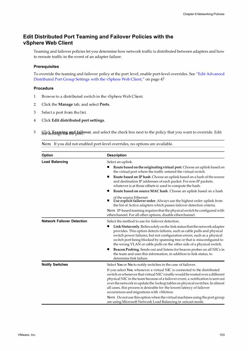
7/15/2019 Vsphere Esxi Vcenter Server 51 Networking Guide
http://slidepdf.com/reader/full/vsphere-esxi-vcenter-server-51-networking-guide-563280a1ebe2b 103/172
Edit Distributed Port Teaming and Failover Policies with thevSphere Web Client
Teaming and failover policies let you determine how network traffic is distributed between adapters and how
to reroute traffic in the event of an adapter failure.
Prerequisites
To override the teaming and failover policy at the port level, enable port-level overrides. See “Edit Advanced
Distributed Port Group Settings with the vSphere Web Client,” on page 47
Procedure
1 Browse to a distributed switch in the vSphere Web Client.
2 Click the Manage tab, and select Ports.
3 Select a port from the list.
4 Click Edit distributed port settings.
5 Click Teaming and failover , and select the check box next to the policy that you want to override. Editthe settings for the port.
NOTE If you did not enabled port-level overrides, no options are available.
Option Description
Load Balancing Select an uplink.
n Route based on the originating virtual port. Choose an uplink based onthe virtual port where the traffic entered the virtual switch.
n Route based on IP hash. Choose an uplink based on a hash of the sourceand destination IP addresses of each packet. For non-IP packets,whatever is at those offsets is used to compute the hash.
n Route based on source MAC hash. Choose an uplink based on a hash
of the source Ethernet.n Use explicit failover order. Always use the highest order uplink from
the list of Active adapters which passes failover detection criteria.
NOTE IP-based teaming requires that the physical switch be configured withetherchannel. For all other options, disable etherchannel.
Network Failover Detection Select the method to use for failover detection.
n Link Status only. Relies solely on the link status that the network adapterprovides. This option detects failures, such as cable pulls and physicalswitch power failures, but not configuration errors, such as a physicalswitch port being blocked by spanning tree or that is misconfigured tothe wrong VLAN or cable pulls on the other side of a physical switch.
n Beacon Probing. Sends out and listens for beacon probes on all NICs inthe team and uses this information, in addition to link status, todetermine link failure.
Notify Switches Select Yes or No to notify switches in the case of failover.
If you select Yes , whenever a virtual NIC is connected to the distributedswitch or whenever that virtual NIC’s traffic would be routed over a differentphysical NIC in the team because of a failover event, a notification is sent outover the network to update the lookup tables on physical switches. In almostall cases, this process is desirable for the lowest latency of failoveroccurrences and migrations with vMotion.
NOTE Do not use this option when the virtual machines using the port groupare using Microsoft Network Load Balancing in unicast mode.
Chapter 6 Networking Policies
VMware, Inc. 103
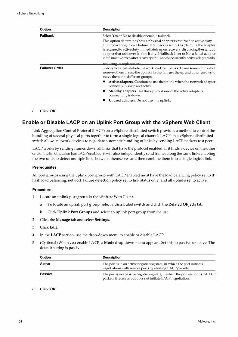
7/15/2019 Vsphere Esxi Vcenter Server 51 Networking Guide
http://slidepdf.com/reader/full/vsphere-esxi-vcenter-server-51-networking-guide-563280a1ebe2b 104/172
Option Description
Failback Select Yes or No to disable or enable failback.
This option determines how a physical adapter is returned to active dutyafter recovering from a failure. If failback is set to Yes (default), the adapteris returned to active duty immediately upon recovery, displacing the standbyadapter that took over its slot, if any. If failback is set to No , a failed adapteris left inactive even after recovery until another currently active adapter fails,
requiring its replacement.Failover Order Specify how to distribute the work load for uplinks. To use some uplinks but
reserve others in case the uplinks in use fail, use the up and down arrows tomove them into different groups:
n Active adapters. Continue to use the uplink when the network adapterconnectivity is up and active.
n Standby adapters. Use this uplink if one of the active adapter’sconnectivity is down.
n Unused adapters. Do not use this uplink.
6 Click OK.
Enable or Disable LACP on an Uplink Port Group with the vSphere Web Client
Link Aggregation Control Protocol (LACP) on a vSphere distributed switch provides a method to control the
bundling of several physical ports together to form a single logical channel. LACP on a vSphere distributed
switch allows network devices to negotiate automatic bundling of links by sending LACP packets to a peer.
LACP works by sending frames down all links that have the protocol enabled. If it finds a device on the other
end of the link that also has LACP enabled, it will also independently send frames along the same links enabling
the two units to detect multiple links between themselves and then combine them into a single logical link.
Prerequisites
All port groups using the uplink port group with LACP enabled must have the load balancing policy set to IP
hash load balancing, network failure detection policy set to link status only, and all uplinks set to active.
Procedure
1 Locate an uplink port group in the vSphere Web Client.
a To locate an uplink port group, select a distributed switch and click the Related Objects tab.
b Click Uplink Port Groups and select an uplink port group from the list.
2 Click the Manage tab and select Settings.
3 Click Edit.
4 In the LACP section, use the drop-down menu to enable or disable LACP.
5 (Optional) When you enable LACP, a Mode drop-down menu appears. Set this to passive or active. The
default setting is passive.
Option Description
Active The port is in an active negotiating state, in which the port initiatesnegotiations with remote ports by sending LACP packets.
Passive The port is in a passive negotiating state, in which the port responds to LACPpackets it receives but does not initiate LACP negotiation.
6 Click OK.
vSphere Networking
104 VMware, Inc.
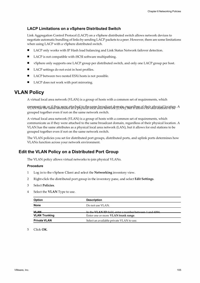
7/15/2019 Vsphere Esxi Vcenter Server 51 Networking Guide
http://slidepdf.com/reader/full/vsphere-esxi-vcenter-server-51-networking-guide-563280a1ebe2b 105/172
LACP Limitations on a vSphere Distributed Switch
Link Aggregation Control Protocol (LACP) on a vSphere distributed switch allows network devices to
negotiate automatic bundling of links by sending LACP packets to a peer. However, there are some limitations
when using LACP with a vSphere distributed switch.
n LACP only works with IP Hash load balancing and Link Status Network failover detection.
n LACP is not compatible with iSCSI software multipathing.
n vSphere only supports one LACP group per distributed switch, and only one LACP group per host.
n LACP settings do not exist in host profiles.
n LACP between two nested ESXi hosts is not possible.
n LACP does not work with port mirroring.
VLAN Policy
A virtual local area network (VLAN) is a group of hosts with a common set of requirements, which
communicate as if they were attached to the same broadcast domain, regardless of their physical location. AVLAN has the same attributes as a physical local area network (LAN), but it allows for end stations to be
grouped together even if not on the same network switch.
A virtual local area network (VLAN) is a group of hosts with a common set of requirements, which
communicate as if they were attached to the same broadcast domain, regardless of their physical location. A
VLAN has the same attributes as a physical local area network (LAN), but it allows for end stations to be
grouped together even if not on the same network switch.
The VLAN policies you set for distributed port groups, distributed ports, and uplink ports determines how
VLANs function across your network environment.
Edit the VLAN Policy on a Distributed Port Group
The VLAN policy allows virtual networks to join physical VLANs.
Procedure
1 Log in to the vSphere Client and select the Networking inventory view.
2 Right-click the distributed port group in the inventory pane, and select Edit Settings.
3 Select Policies.
4 Select the VLAN Type to use.
Option Description
None Do not use VLAN.
VLAN In the VLAN ID field, enter a number between 1 and 4094.VLAN Trunking Enter one or more VLAN trunk range.
Private VLAN Select an available private VLAN to use.
5 Click OK.
Chapter 6 Networking Policies
VMware, Inc. 105
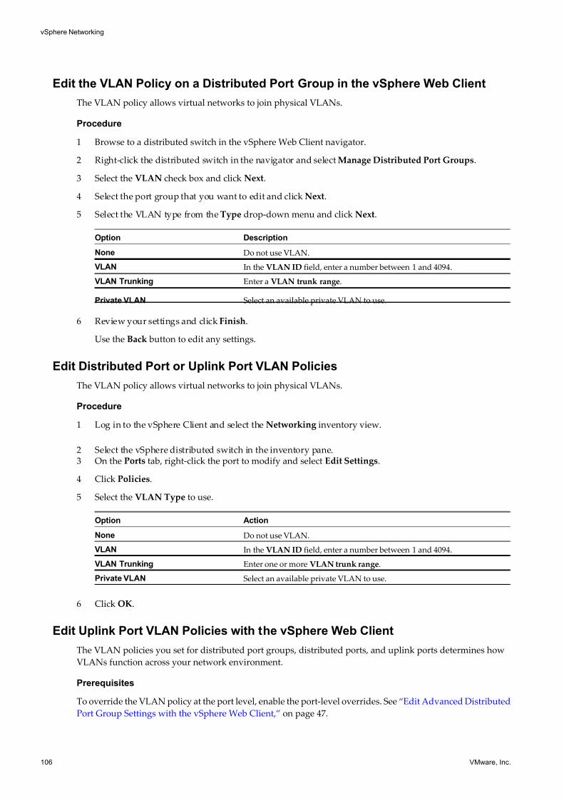
7/15/2019 Vsphere Esxi Vcenter Server 51 Networking Guide
http://slidepdf.com/reader/full/vsphere-esxi-vcenter-server-51-networking-guide-563280a1ebe2b 106/172
Edit the VLAN Policy on a Distributed Port Group in the vSphere Web Client
The VLAN policy allows virtual networks to join physical VLANs.
Procedure
1 Browse to a distributed switch in the vSphere Web Client navigator.
2 Right-click the distributed switch in the navigator and select Manage Distributed Port Groups.
3 Select the VLAN check box and click Next.
4 Select the port group that you want to edit and click Next.
5 Select the VLAN type from the Type drop-down menu and click Next.
Option Description
None Do not use VLAN.
VLAN In the VLAN ID field, enter a number between 1 and 4094.
VLAN Trunking Enter a VLAN trunk range.
Private VLAN Select an available private VLAN to use.
6 Review your settings and click Finish.
Use the Back button to edit any settings.
Edit Distributed Port or Uplink Port VLAN Policies
The VLAN policy allows virtual networks to join physical VLANs.
Procedure
1 Log in to the vSphere Client and select the Networking inventory view.
2 Select the vSphere distributed switch in the inventory pane.3 On the Ports tab, right-click the port to modify and select Edit Settings.
4 Click Policies.
5 Select the VLAN Type to use.
Option Action
None Do not use VLAN.
VLAN In the VLAN ID field, enter a number between 1 and 4094.
VLAN Trunking Enter one or more VLAN trunk range.
Private VLAN Select an available private VLAN to use.
6 Click OK.
Edit Uplink Port VLAN Policies with the vSphere Web Client
The VLAN policies you set for distributed port groups, distributed ports, and uplink ports determines how
VLANs function across your network environment.
Prerequisites
To override the VLAN policy at the port level, enable the port-level overrides. See “Edit Advanced Distributed
Port Group Settings with the vSphere Web Client,” on page 47.
vSphere Networking
106 VMware, Inc.
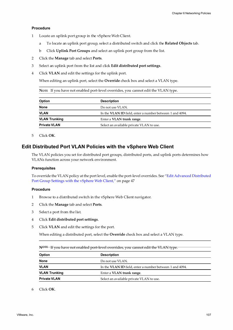
7/15/2019 Vsphere Esxi Vcenter Server 51 Networking Guide
http://slidepdf.com/reader/full/vsphere-esxi-vcenter-server-51-networking-guide-563280a1ebe2b 107/172
Procedure
1 Locate an uplink port group in the vSphere Web Client.
a To locate an uplink port group, select a distributed switch and click the Related Objects tab.
b Click Uplink Port Groups and select an uplink port group from the list.
2 Click the Manage tab and select Ports.
3 Select an uplink port from the list and click Edit distributed port settings.
4 Click VLAN and edit the settings for the uplink port.
When editing an uplink port, select the Override check box and select a VLAN type.
NOTE If you have not enabled port-level overrides, you cannot edit the VLAN type.
Option Description
None Do not use VLAN.
VLAN In the VLAN ID field, enter a number between 1 and 4094.
VLAN Trunking Enter a VLAN trunk range.
Private VLAN Select an available private VLAN to use.
5 Click OK.
Edit Distributed Port VLAN Policies with the vSphere Web Client
The VLAN policies you set for distributed port groups, distributed ports, and uplink ports determines how
VLANs function across your network environment.
Prerequisites
To override the VLAN policy at the port level, enable the port-level overrides. See “Edit Advanced Distributed
Port Group Settings with the vSphere Web Client,” on page 47
Procedure
1 Browse to a distributed switch in the vSphere Web Client navigator.
2 Click the Manage tab and select Ports.
3 Select a port from the list.
4 Click Edit distributed port settings.
5 Click VLAN and edit the settings for the port.
When editing a distributed port, select the Override check box and select a VLAN type.
NOTE If you have not enabled port-level overrides, you cannot edit the VLAN type.
Option Description
None Do not use VLAN.
VLAN In the VLAN ID field, enter a number between 1 and 4094.
VLAN Trunking Enter a VLAN trunk range.
Private VLAN Select an available private VLAN to use.
6 Click OK.
Chapter 6 Networking Policies
VMware, Inc. 107
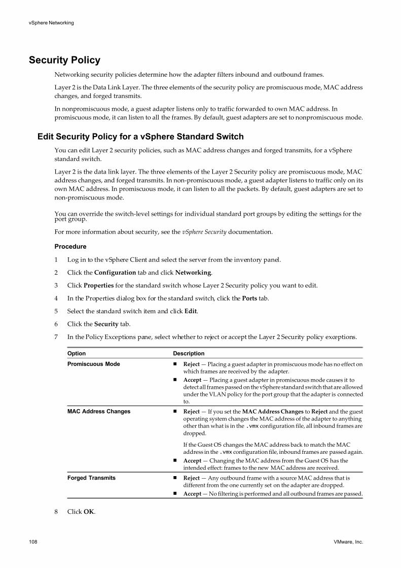
7/15/2019 Vsphere Esxi Vcenter Server 51 Networking Guide
http://slidepdf.com/reader/full/vsphere-esxi-vcenter-server-51-networking-guide-563280a1ebe2b 108/172
Security Policy
Networking security policies determine how the adapter filters inbound and outbound frames.
Layer 2 is the Data Link Layer. The three elements of the security policy are promiscuous mode, MAC address
changes, and forged transmits.
In nonpromiscuous mode, a guest adapter listens only to traffic forwarded to own MAC address. In
promiscuous mode, it can listen to all the frames. By default, guest adapters are set to nonpromiscuous mode.
Edit Security Policy for a vSphere Standard Switch
You can edit Layer 2 security policies, such as MAC address changes and forged transmits, for a vSphere
standard switch.
Layer 2 is the data link layer. The three elements of the Layer 2 Security policy are promiscuous mode, MAC
address changes, and forged transmits. In non-promiscuous mode, a guest adapter listens to traffic only on its
own MAC address. In promiscuous mode, it can listen to all the packets. By default, guest adapters are set to
non-promiscuous mode.
You can override the switch-level settings for individual standard port groups by editing the settings for theport group.
For more information about security, see the vSphere Security documentation.
Procedure
1 Log in to the vSphere Client and select the server from the inventory panel.
2 Click the Configuration tab and click Networking.
3 Click Properties for the standard switch whose Layer 2 Security policy you want to edit.
4 In the Properties dialog box for the standard switch, click the Ports tab.
5 Select the standard switch item and click Edit.
6 Click the Security tab.
7 In the Policy Exceptions pane, select whether to reject or accept the Layer 2 Security policy exceptions.
Option Description
Promiscuous Mode n Reject — Placing a guest adapter in promiscuous mode has no effect onwhich frames are received by the adapter.
n Accept — Placing a guest adapter in promiscuous mode causes it todetect all frames passed on the vSphere standard switch that are allowedunder the VLAN policy for the port group that the adapter is connectedto.
MAC Address Changes n Reject — If you set the MAC Address Changes to Reject and the guestoperating system changes the MAC address of the adapter to anythingother than what is in the .vmx configuration file, all inbound frames are
dropped.
If the Guest OS changes the MAC address back to match the MACaddress in the .vmx configuration file, inbound frames are passed again.
n Accept — Changing the MAC address from the Guest OS has theintended effect: frames to the new MAC address are received.
Forged Transmits n Reject — Any outbound frame with a source MAC address that isdifferent from the one currently set on the adapter are dropped.
n Accept — No filtering is performed and all outbound frames are passed.
8 Click OK.
vSphere Networking
108 VMware, Inc.
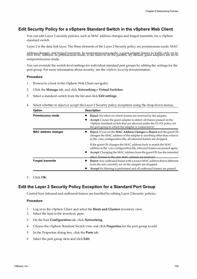
7/15/2019 Vsphere Esxi Vcenter Server 51 Networking Guide
http://slidepdf.com/reader/full/vsphere-esxi-vcenter-server-51-networking-guide-563280a1ebe2b 109/172
Edit Security Policy for a vSphere Standard Switch in the vSphere Web Client
You can edit Layer 2 security policies, such as MAC address changes and forged transmits, for a vSphere
standard switch.
Layer 2 is the data link layer. The three elements of the Layer 2 Security policy are promiscuous mode, MAC
address changes, and forged transmits. In nonpromiscuous mode, a guest adapter listens to traffic only on itsown MAC address. In promiscuous mode, it can listen to all the packets. By default, guest adapters are set to
nonpromiscuous mode.
You can override the switch-level settings for individual standard port groups by editing the settings for the
port group. For more information about security, see the vSphere Security documentation.
Procedure
1 Browse to a host in the vSphere Web Client navigator.
2 Click the Manage tab, and click Networking > Virtual Switches.
3 Select a standard switch from the list and click Edit settings.
4 Select whether to reject or accept the Layer 2 Security policy exceptions using the drop-down menus.
Option Description
Promiscuous mode n Reject: No effect on which frames are received by the adapter.
n Accept: Causes the guest adapter to detect all frames passed on thevSphere standard switch that are allowed under the VLAN policy forthe port group to which the adapter is connected to.
MAC address changes n Reject: If you set the MAC Address Changes to Reject and the guest OSchanges the MAC address of the adapter to anything other than what isin the .vmx configuration file, all inbound frames are dropped.
If the guest OS changes the MAC address back to match the MACaddress in the .vmx configuration file, inbound frames are passed again.
n Accept: Changing the MAC address from the guest OS has the intended
effect. Frames to the new MAC address are received.
Forged transmits n Reject: Any outbound frame with a source MAC address that is differentfrom the one currently set on the adapter are dropped.
n Accept:No filtering is performed and all outbound frames are passed.
5 Click OK.
Edit the Layer 2 Security Policy Exception for a Standard Port Group
Control how inbound and outbound frames are handled by editing Layer 2 Security policies.
Procedure
1 Log in to the vSphere Client and select the Hosts and Clusters inventory view.
2 Select the host in the inventory pane.
3 On the host Configuration tab, click Networking.
4 Choose the vSphere Standard Switch view and click Properties for the port group to edit.
5 In the Properties dialog box, click the Ports tab.
6 Select the port group item and click Edit.
Chapter 6 Networking Policies
VMware, Inc. 109
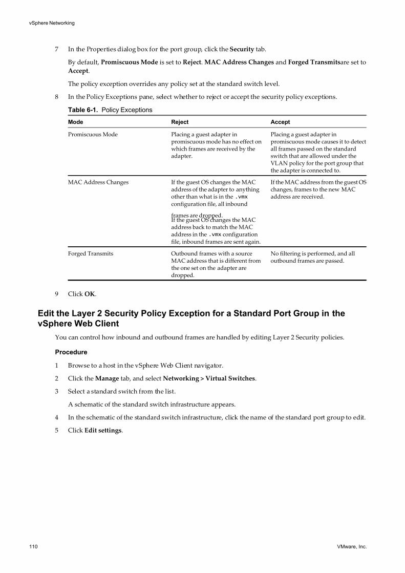
7/15/2019 Vsphere Esxi Vcenter Server 51 Networking Guide
http://slidepdf.com/reader/full/vsphere-esxi-vcenter-server-51-networking-guide-563280a1ebe2b 110/172
7 In the Properties dialog box for the port group, click the Security tab.
By default, Promiscuous Mode is set to Reject. MAC Address Changes and Forged Transmitsare set to
Accept.
The policy exception overrides any policy set at the standard switch level.
8 In the Policy Exceptions pane, select whether to reject or accept the security policy exceptions.
Table 6-1. Policy Exceptions
Mode Reject Accept
Promiscuous Mode Placing a guest adapter inpromiscuous mode has no effect onwhich frames are received by theadapter.
Placing a guest adapter inpromiscuous mode causes it to detectall frames passed on the standardswitch that are allowed under theVLAN policy for the port group thatthe adapter is connected to.
MAC Address Changes If the guest OS changes the MACaddress of the adapter to anythingother than what is in the .vmx
configuration file, all inbound
frames are dropped.If the guest OS changes the MACaddress back to match the MACaddress in the .vmx configuration
file, inbound frames are sent again.
If the MAC address from the guest OSchanges, frames to the new MACaddress are received.
Forged Transmits Outbound frames with a sourceMAC address that is different fromthe one set on the adapter aredropped.
No filtering is performed, and alloutbound frames are passed.
9 Click OK.
Edit the Layer 2 Security Policy Exception for a Standard Port Group in thevSphere Web Client
You can control how inbound and outbound frames are handled by editing Layer 2 Security policies.
Procedure
1 Browse to a host in the vSphere Web Client navigator.
2 Click the Manage tab, and select Networking > Virtual Switches.
3 Select a standard switch from the list.
A schematic of the standard switch infrastructure appears.
4 In the schematic of the standard switch infrastructure, click the name of the standard port group to edit.
5 Click Edit settings.
vSphere Networking
110 VMware, Inc.
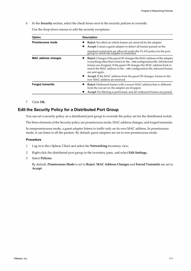
7/15/2019 Vsphere Esxi Vcenter Server 51 Networking Guide
http://slidepdf.com/reader/full/vsphere-esxi-vcenter-server-51-networking-guide-563280a1ebe2b 111/172
6 In the Security section, select the check boxes next to the security policies to override.
Use the drop-down menus to edit the security exceptions.
Option Description
Promiscuous mode n Reject: No effect on which frames are received by the adapter.
n Accept: Causes a guest adapter to detect all frames passed on the
standard switch that are allowed under the VLAN policy for the portgroup to which the adapter is connected.
MAC address changes n Reject: Changes if the guest OS changes the MAC address of the adapterto anything other than what is in the.vmx configuration file. All inbound
frames are dropped. If the guest OS changes the MAC address back tomatch the MAC address in the .vmx configuration file, inbound frames
are sent again.
n Accept: If the MAC address from the guest OS changes, frames to thenew MAC address are received.
Forged transmits n Reject: Outbound frames with a source MAC address that is differentfrom the one set on the adapter are dropped.
n Accept: No filtering is performed, and all outbound frames are passed.
7 Click OK.
Edit the Security Policy for a Distributed Port Group
You can set a security policy on a distributed port group to override the policy set for the distributed switch.
The three elements of the Security policy are promiscuous mode, MAC address changes, and forged transmits.
In nonpromiscuous mode, a guest adapter listens to traffic only on its own MAC address. In promiscuous
mode, it can listen to all the packets. By default, guest adapters are set to non-promiscuous mode.
Procedure
1 Log in to the vSphere Client and select the Networking inventory view.
2 Right-click the distributed port group in the inventory pane, and select Edit Settings.
3 Select Policies.
By default, Promiscuous Mode is set to Reject. MAC Address Changes and Forced Transmits are set to
Accept.
Chapter 6 Networking Policies
VMware, Inc. 111
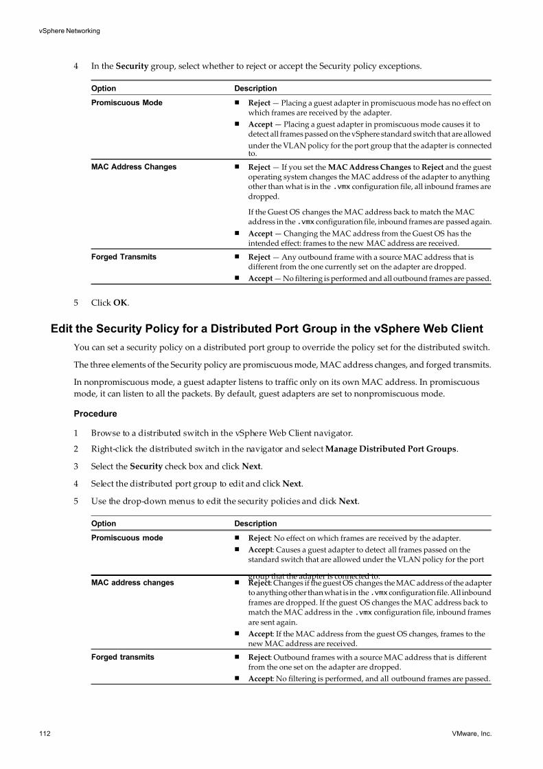
7/15/2019 Vsphere Esxi Vcenter Server 51 Networking Guide
http://slidepdf.com/reader/full/vsphere-esxi-vcenter-server-51-networking-guide-563280a1ebe2b 112/172
4 In the Security group, select whether to reject or accept the Security policy exceptions.
Option Description
Promiscuous Mode n Reject — Placing a guest adapter in promiscuous mode has no effect onwhich frames are received by the adapter.
n Accept — Placing a guest adapter in promiscuous mode causes it todetect all frames passed on the vSphere standard switch that are allowed
under the VLAN policy for the port group that the adapter is connectedto.
MAC Address Changes n Reject — If you set the MAC Address Changes to Reject and the guestoperating system changes the MAC address of the adapter to anythingother than what is in the .vmx configuration file, all inbound frames are
dropped.
If the Guest OS changes the MAC address back to match the MACaddress in the .vmx configuration file, inbound frames are passed again.
n Accept — Changing the MAC address from the Guest OS has theintended effect: frames to the new MAC address are received.
Forged Transmits n Reject — Any outbound frame with a source MAC address that isdifferent from the one currently set on the adapter are dropped.
n Accept — No filtering is performed and all outbound frames are passed.
5 Click OK.
Edit the Security Policy for a Distributed Port Group in the vSphere Web Client
You can set a security policy on a distributed port group to override the policy set for the distributed switch.
The three elements of the Security policy are promiscuous mode, MAC address changes, and forged transmits.
In nonpromiscuous mode, a guest adapter listens to traffic only on its own MAC address. In promiscuous
mode, it can listen to all the packets. By default, guest adapters are set to nonpromiscuous mode.
Procedure
1 Browse to a distributed switch in the vSphere Web Client navigator.
2 Right-click the distributed switch in the navigator and select Manage Distributed Port Groups.
3 Select the Security check box and click Next.
4 Select the distributed port group to edit and click Next.
5 Use the drop-down menus to edit the security policies and click Next.
Option Description
Promiscuous mode n Reject: No effect on which frames are received by the adapter.
n Accept: Causes a guest adapter to detect all frames passed on thestandard switch that are allowed under the VLAN policy for the port
group that the adapter is connected to.MAC address changes n Reject: Changes if the guest OS changes the MAC address of the adapter
to anything other than what is in the.vmx configuration file. All inbound
frames are dropped. If the guest OS changes the MAC address back tomatch the MAC address in the .vmx configuration file, inbound frames
are sent again.
n Accept: If the MAC address from the guest OS changes, frames to thenew MAC address are received.
Forged transmits n Reject: Outbound frames with a source MAC address that is differentfrom the one set on the adapter are dropped.
n Accept: No filtering is performed, and all outbound frames are passed.
vSphere Networking
112 VMware, Inc.
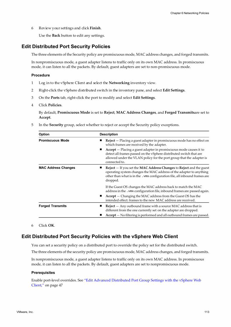
7/15/2019 Vsphere Esxi Vcenter Server 51 Networking Guide
http://slidepdf.com/reader/full/vsphere-esxi-vcenter-server-51-networking-guide-563280a1ebe2b 113/172
6 Review your settings and click Finish.
Use the Back button to edit any settings.
Edit Distributed Port Security Policies
The three elements of the Security policy are promiscuous mode, MAC address changes, and forged transmits.
In nonpromiscuous mode, a guest adapter listens to traffic only on its own MAC address. In promiscuous
mode, it can listen to all the packets. By default, guest adapters are set to non-promiscuous mode.
Procedure
1 Log in to the vSphere Client and select the Networking inventory view.
2 Right-click the vSphere distributed switch in the inventory pane, and select Edit Settings.
3 On the Ports tab, right-click the port to modify and select Edit Settings.
4 Click Policies.
By default, Promiscuous Mode is set to Reject , MAC Address Changes , and Forged Transmitsare set to
Accept.
5 In the Security group, select whether to reject or accept the Security policy exceptions.
Option Description
Promiscuous Mode n Reject — Placing a guest adapter in promiscuous mode has no effect onwhich frames are received by the adapter.
n Accept — Placing a guest adapter in promiscuous mode causes it todetect all frames passed on the vSphere distributed switch that areallowed under the VLAN policy for the port group that the adapter isconnected to.
MAC Address Changes n Reject — If you set the MAC Address Changes to Reject and the guestoperating system changes the MAC address of the adapter to anythingother than what is in the .vmx configuration file, all inbound frames are
dropped.
If the Guest OS changes the MAC address back to match the MACaddress in the .vmx configuration file, inbound frames are passed again.
n Accept — Changing the MAC address from the Guest OS has theintended effect: frames to the new MAC address are received.
Forged Transmits n Reject — Any outbound frame with a source MAC address that isdifferent from the one currently set on the adapter are dropped.
n Accept — No filtering is performed and all outbound frames are passed.
6 Click OK.
Edit Distributed Port Security Policies with the vSphere Web Client
You can set a security policy on a distributed port to override the policy set for the distributed switch.
The three elements of the security policy are promiscuous mode, MAC address changes, and forged transmits.
In nonpromiscuous mode, a guest adapter listens to traffic only on its own MAC address. In promiscuous
mode, it can listen to all the packets. By default, guest adapters are set to nonpromiscuous mode.
Prerequisites
Enable port-level overrides. See “Edit Advanced Distributed Port Group Settings with the vSphere Web
Client,” on page 47
Chapter 6 Networking Policies
VMware, Inc. 113
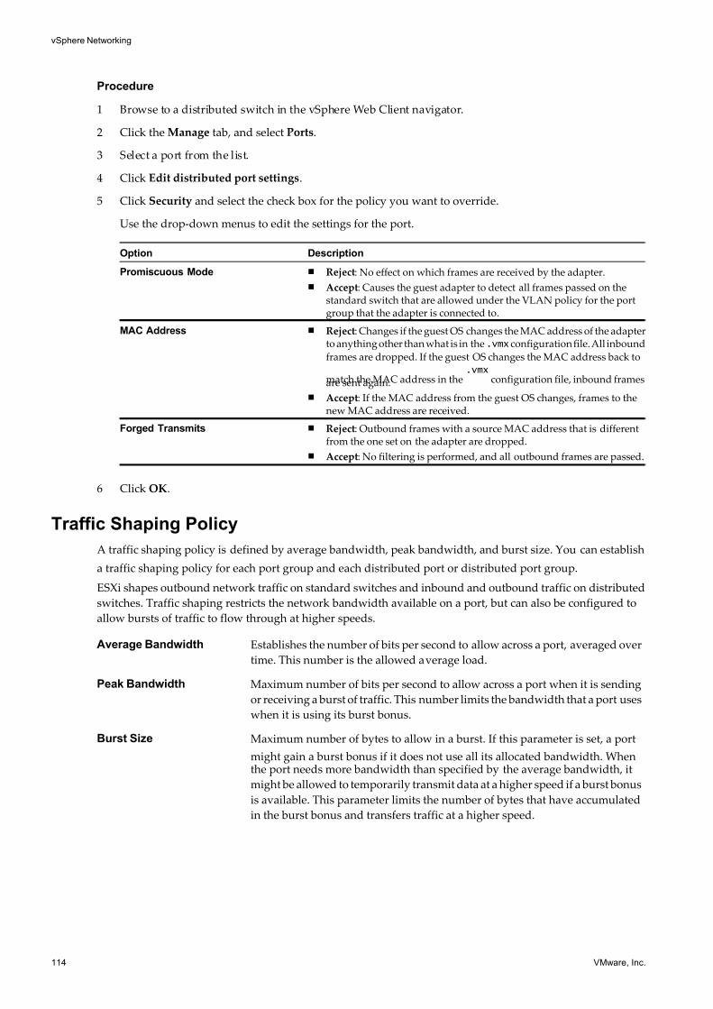
7/15/2019 Vsphere Esxi Vcenter Server 51 Networking Guide
http://slidepdf.com/reader/full/vsphere-esxi-vcenter-server-51-networking-guide-563280a1ebe2b 114/172
Procedure
1 Browse to a distributed switch in the vSphere Web Client navigator.
2 Click the Manage tab, and select Ports.
3 Select a port from the list.
4 Click Edit distributed port settings.
5 Click Security and select the check box for the policy you want to override.
Use the drop-down menus to edit the settings for the port.
Option Description
Promiscuous Mode n Reject: No effect on which frames are received by the adapter.
n Accept: Causes the guest adapter to detect all frames passed on thestandard switch that are allowed under the VLAN policy for the portgroup that the adapter is connected to.
MAC Address n Reject: Changes if the guest OS changes the MAC address of the adapterto anything other than what is in the.vmx configuration file. All inbound
frames are dropped. If the guest OS changes the MAC address back to
match the MAC address in the.vmx
configuration file, inbound framesare sent again.
n Accept: If the MAC address from the guest OS changes, frames to thenew MAC address are received.
Forged Transmits n Reject: Outbound frames with a source MAC address that is differentfrom the one set on the adapter are dropped.
n Accept: No filtering is performed, and all outbound frames are passed.
6 Click OK.
Traffic Shaping Policy
A traffic shaping policy is defined by average bandwidth, peak bandwidth, and burst size. You can establish
a traffic shaping policy for each port group and each distributed port or distributed port group.
ESXi shapes outbound network traffic on standard switches and inbound and outbound traffic on distributed
switches. Traffic shaping restricts the network bandwidth available on a port, but can also be configured to
allow bursts of traffic to flow through at higher speeds.
Average Bandwidth Establishes the number of bits per second to allow across a port, averaged over
time. This number is the allowed average load.
Peak Bandwidth Maximum number of bits per second to allow across a port when it is sending
or receiving a burst of traffic. This number limits the bandwidth that a port uses
when it is using its burst bonus.
Burst Size Maximum number of bytes to allow in a burst. If this parameter is set, a port
might gain a burst bonus if it does not use all its allocated bandwidth. Whenthe port needs more bandwidth than specified by the average bandwidth, it
might be allowed to temporarily transmit data at a higher speed if a burst bonus
is available. This parameter limits the number of bytes that have accumulated
in the burst bonus and transfers traffic at a higher speed.
vSphere Networking
114 VMware, Inc.
7/15/2019 Vsphere Esxi Vcenter Server 51 Networking Guide
http://slidepdf.com/reader/full/vsphere-esxi-vcenter-server-51-networking-guide-563280a1ebe2b 115/172
Edit the Traffic Shaping Policy for a vSphere Standard Switch
ESXi allows you to shape outbound traffic on standard switches. The traffic shaper restricts the network
bandwidth available to any port, but may also be configured to temporarily allow “bursts” of traffic to flow
through a port at higher speeds.
A traffic shaping policy is defined by three characteristics: average bandwidth, peak bandwidth, and burstsize.
Average Bandwidth Establishes the number of bits per second to allow across a port, averaged over
time—the allowed average load.
Burst Size The maximum number of bytes to allow in a burst. If this parameter is set, a
port may gain a burst bonus when it doesn’t use all its allocated bandwidth.
Whenever the port needs more bandwidth than specified by Average
Bandwidth , it may be allowed to temporarily transmit data at a higher speed
if a burst bonus is available. This parameter tops the number of bytes that may
be accumulated in the burst bonus and thus transferred at a higher speed.
Peak Bandwidth The maximum number of bits per second to allow across a port when it is
sending a burst of traffic. This tops the bandwidth used by a port whenever it
is using its burst bonus. This parameter can never be smaller than the average
bandwidth.
Procedure
1 Log in to the vSphere Client and select the server from the inventory panel.
2 Click the Configuration tab and click Networking.
3 Select a standard switch and click Properties.
4 Click the Ports tab.
5 Select the standard switch and click Edit.
6 Click the Traffic Shaping tab.
7 Select Enabled from the Status drop-down menu to enable traffic shaping policy exceptions.
The Status policy here is applied to each virtual adapter attached to the port group, not to the standard
switch as a whole. If you enable the policy exception in the Status field, you set limits on the amount of
networking bandwidth allocation for each virtual adapter associated with this particular port group. If
you disable the policy, services have a clear connection to the physical network by default.
8 For each traffic shaping policy, enter a bandwidth value.
Chapter 6 Networking Policies
VMware, Inc. 115
7/15/2019 Vsphere Esxi Vcenter Server 51 Networking Guide
http://slidepdf.com/reader/full/vsphere-esxi-vcenter-server-51-networking-guide-563280a1ebe2b 116/172
Edit the Traffic Shaping Policy for a vSphere Standard Switch in thevSphere Web Client
ESXi allows you to shape outbound traffic on standard switches. The traffic shaper restricts the network
bandwidth available to any port, but you can also configure it to temporarily allow bursts of traffic to flow
through a port at higher speeds.
A traffic shaping policy is defined by three characteristics: average bandwidth, peak bandwidth, and burst
size.
Average Bandwidth Establishes the number of bits per second to allow across a port, averaged over
time (the allowed average load).
Peak Bandwidth The maximum number of bits per second to allow across a port when it is
sending a burst of traffic. This tops the bandwidth used by a port whenever it
is using its burst bonus. This parameter can never be smaller than the average
bandwidth.
Burst Size The maximum number of bytes to allow in a burst. If this parameter is set, a
port might gain a burst bonus when it does not use all its allocated bandwidth.
Whenever the port needs more bandwidth than specified by Average
Bandwidth , it might be allowed to temporarily transmit data at a higher speed
if a burst bonus is available. This parameter tops the number of bytes that can
be accumulated in the burst bonus and transferred at a higher speed.
Procedure
1 Browse to a host in the vSphere Web Client navigator.
2 Click the Manage tab, and click Networking > Virtual Switches.
3 Select a standard switch from the list and click Edit settings.
4 Click Traffic shaping and enable or disable traffic shaping policy exceptions with the Status drop-down
menu.
The Status policy is applied to each virtual adapter attached to the port group, not to the standard switch
as a whole. If you enable the traffic policy exception, you set limits on the amount of networking bandwidth
allocation for each virtual adapter associated with this particular port group. If you disable the policy,
services have a clear connection to the physical network by default.
5 For each traffic shaping policy (Average Bandwidth , Peak Bandwidth , and Burst Size), enter a bandwidth
value.
6 Click OK.
Edit the Traffic Shaping Policy for a Standard Port Group
Use traffic shaping policies to control the bandwidth and burst size on a port group.
Procedure
1 Log in to the vSphere Client and select the Hosts and Clusters inventory view.
2 Select the host in the inventory pane.
3 On the host Configuration tab, click Networking.
4 Choose the vSphere Standard Switch view and click Properties for the port group to edit.
5 In the Properties dialog box, click the Ports tab.
vSphere Networking
116 VMware, Inc.
7/15/2019 Vsphere Esxi Vcenter Server 51 Networking Guide
http://slidepdf.com/reader/full/vsphere-esxi-vcenter-server-51-networking-guide-563280a1ebe2b 117/172
6 Select the port group item and click Edit.
7 In the Properties dialog box for the port group, click the Traffic Shaping tab.
When traffic shaping is disabled, the options are dimmed.
Option Description
StatusIf you enable the policy exception in the Status field, you are setting limitson the amount of networking bandwidth allocated for each virtual adapterassociated with this particular port group. If you disable the policy, serviceshave a free and clear connection to the physical network.
Average Bandwidth A value measured over a particular period of time.
Peak Bandwidth Limits the maximum bandwidth during a burst. It can never be smaller thanthe average bandwidth.
Burst Size Specifies how large a burst can be in kilobytes (KB).
Edit the Traffic Shaping Policy for a Standard Port Group in thevSphere Web Client
Use traffic shaping policies to control the bandwidth and burst size on a port group.
Prerequisites
Enable the port-level overrides. See “Edit Advanced Distributed Port Group Settings with the vSphere Web
Client,” on page 47
Procedure
1 Browse to a host in the vSphere Web Client navigator.
2 Click the Manage tab, and click Networking > Virtual Switches.
3 Select a standard switch from the list.
A schematic of the standard switch infrastructure appears.
4 Click Edit settings.
5 Click Traffic Shaping and click the Override check box to override the traffic shaping policy at the
standard port group level and enter settings.
NOTE If you have not enabled port group-level overrides, the options are not available.
Option Description
Status If you enable the policy exception in the Status field, you are setting limitson the amount of networking bandwidth allocated for each virtual adapterassociated with this particular port group. If you disable the policy, serviceshave a free and clear connection to the physical network.
Average Bandwidth A value measured over a particular period of time.
Peak Bandwidth Limits the maximum bandwidth during a burst. It can never be smaller thanthe average bandwidth.
Burst Size Specifies how large a burst can be in kilobytes (KB).
6 Click OK.
Chapter 6 Networking Policies
VMware, Inc. 117
7/15/2019 Vsphere Esxi Vcenter Server 51 Networking Guide
http://slidepdf.com/reader/full/vsphere-esxi-vcenter-server-51-networking-guide-563280a1ebe2b 118/172
Edit the Traffic Shaping Policy for a Distributed Port Group
ESXi allows you to shape both inbound and outbound traffic on vSphere distributed switches. The traffic shaper
restricts the network bandwidth available to any port, but may also be configured to temporarily allow “bursts”
of traffic to flow through a port at higher speeds.
A traffic shaping policy is defined by three characteristics: average bandwidth, peak bandwidth, and burstsize.
Procedure
1 Log in to the vSphere Client and select the Networking inventory view.
2 Right-click the distributed port group in the inventory pane, and select Edit Settings.
3 Select Policies.
4 In the Traffic Shaping group, you can configure both Ingress Traffic Shaping and EgressTraffic
Shaping.
When traffic shaping is disabled, the tunable features are dimmed.
Status — If you enable the policy exception for either Ingress Traffic Shaping or Egress TrafficShaping in the Status field, you are setting limits on the amount of networking bandwidth allocated for
each virtual adapter associated with this particular port group. If you disable the policy, services have a
free, clear connection to the physical network by default.
5 Specify network traffic parameters.
Option Description
Average Bandwidth Establishes the number of bits per second to allow across a port, averagedover time—the allowed average load.
Peak Bandwidth The maximum number of bits per second to allow across a port when it issending/receiving a burst of traffic. This tops the bandwidth used by a portwhenever it is using its burst bonus.
Burst Size The maximum number of bytes to allow in a burst. If this parameter is set, aport may gain a burst bonus when it doesn’t use all its allocated bandwidth.Whenever the port needs more bandwidth than specified by AverageBandwidth , it may be allowed to temporarily transmit data at a higher speedif a burst bonus is available. This parameter tops the number of bytes thatmay be accumulated in the burst bonus and thus transferred at a higherspeed.
6 Click OK.
Edit the Traffic Shaping Policy for a Distributed Port Group in thevSphere Web Client
ESXi allows you to shape both inbound and outbound traffic on vSphere distributed port groups. The trafficshaper restricts the network bandwidth available to any port, but may also be configured to temporarily allow
“bursts” of traffic to flow through a port at higher speeds.
A traffic shaping policy is defined by three characteristics: average bandwidth, peak bandwidth, and burst
size.
Procedure
1 Browse to a distributed switch in the vSphere Web Client navigator.
2 Right-click the distributed switch in the navigator and select Manage Distributed Port Groups.
3 Select the Traffic Shaping check box and click Next.
vSphere Networking
118 VMware, Inc.
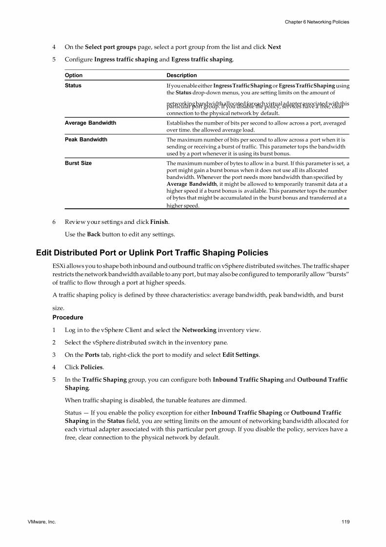
7/15/2019 Vsphere Esxi Vcenter Server 51 Networking Guide
http://slidepdf.com/reader/full/vsphere-esxi-vcenter-server-51-networking-guide-563280a1ebe2b 119/172
4 On the Select port groups page, select a port group from the list and click Next
5 Configure Ingress traffic shaping and Egress traffic shaping.
Option Description
Status If you enable either Ingress Traffic Shaping or Egress Traffic Shaping usingthe Status drop-down menus, you are setting limits on the amount of
networking bandwidth allocated for each virtual adapter associated with thisparticular port group. If you disable the policy, services have a free, clearconnection to the physical network by default.
Average Bandwidth Establishes the number of bits per second to allow across a port, averagedover time. the allowed average load.
Peak Bandwidth The maximum number of bits per second to allow across a port when it issending or receiving a burst of traffic. This parameter tops the bandwidthused by a port whenever it is using its burst bonus.
Burst Size The maximum number of bytes to allow in a burst. If this parameter is set, aport might gain a burst bonus when it does not use all its allocated bandwidth. Whenever the port needs more bandwidth than specified byAverage Bandwidth , it might be allowed to temporarily transmit data at ahigher speed if a burst bonus is available. This parameter tops the numberof bytes that might be accumulated in the burst bonus and transferred at a
higher speed.
6 Review your settings and click Finish.
Use the Back button to edit any settings.
Edit Distributed Port or Uplink Port Traffic Shaping Policies
ESXi allows you to shape both inbound and outbound traffic on vSphere distributed switches. The traffic shaper
restricts the network bandwidth available to any port, but may also be configured to temporarily allow “bursts”
of traffic to flow through a port at higher speeds.
A traffic shaping policy is defined by three characteristics: average bandwidth, peak bandwidth, and burst
size.
Procedure
1 Log in to the vSphere Client and select the Networking inventory view.
2 Select the vSphere distributed switch in the inventory pane.
3 On the Ports tab, right-click the port to modify and select Edit Settings.
4 Click Policies.
5 In the Traffic Shaping group, you can configure both Inbound Traffic Shaping and Outbound Traffic
Shaping.
When traffic shaping is disabled, the tunable features are dimmed.
Status — If you enable the policy exception for either Inbound Traffic Shaping or Outbound Traffic
Shaping in the Status field, you are setting limits on the amount of networking bandwidth allocated for
each virtual adapter associated with this particular port group. If you disable the policy, services have a
free, clear connection to the physical network by default.
Chapter 6 Networking Policies
VMware, Inc. 119
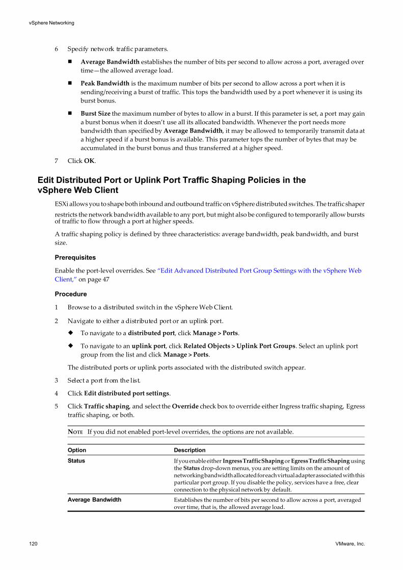
7/15/2019 Vsphere Esxi Vcenter Server 51 Networking Guide
http://slidepdf.com/reader/full/vsphere-esxi-vcenter-server-51-networking-guide-563280a1ebe2b 120/172
6 Specify network traffic parameters.
n Average Bandwidth establishes the number of bits per second to allow across a port, averaged over
time—the allowed average load.
n Peak Bandwidth is the maximum number of bits per second to allow across a port when it is
sending/receiving a burst of traffic. This tops the bandwidth used by a port whenever it is using its
burst bonus.
n Burst Size the maximum number of bytes to allow in a burst. If this parameter is set, a port may gain
a burst bonus when it doesn’t use all its allocated bandwidth. Whenever the port needs more
bandwidth than specified by Average Bandwidth , it may be allowed to temporarily transmit data at
a higher speed if a burst bonus is available. This parameter tops the number of bytes that may be
accumulated in the burst bonus and thus transferred at a higher speed.
7 Click OK.
Edit Distributed Port or Uplink Port Traffic Shaping Policies in thevSphere Web Client
ESXi allows you to shape both inbound and outbound traffic on vSphere distributed switches. The traffic shaper
restricts the network bandwidth available to any port, but might also be configured to temporarily allow burstsof traffic to flow through a port at higher speeds.
A traffic shaping policy is defined by three characteristics: average bandwidth, peak bandwidth, and burst
size.
Prerequisites
Enable the port-level overrides. See “Edit Advanced Distributed Port Group Settings with the vSphere Web
Client,” on page 47
Procedure
1 Browse to a distributed switch in the vSphere Web Client.
2 Navigate to either a distributed port or an uplink port.
u To navigate to a distributed port , click Manage > Ports.
u To navigate to an uplink port , click Related Objects > Uplink Port Groups. Select an uplink port
group from the list and click Manage > Ports.
The distributed ports or uplink ports associated with the distributed switch appear.
3 Select a port from the list.
4 Click Edit distributed port settings.
5 Click Traffic shaping , and select the Override check box to override either Ingress traffic shaping, Egress
traffic shaping, or both.
NOTE If you did not enabled port-level overrides, the options are not available.
Option Description
Status If you enable either Ingress Traffic Shaping or Egress Traffic Shaping usingthe Status drop-down menus, you are setting limits on the amount ofnetworking bandwidth allocated for each virtual adapter associated with thisparticular port group. If you disable the policy, services have a free, clearconnection to the physical network by default.
Average Bandwidth Establishes the number of bits per second to allow across a port, averagedover time, that is, the allowed average load.
vSphere Networking
120 VMware, Inc.
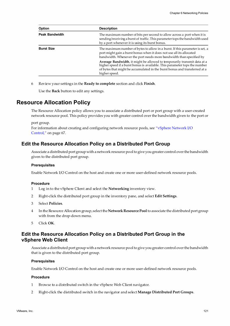
7/15/2019 Vsphere Esxi Vcenter Server 51 Networking Guide
http://slidepdf.com/reader/full/vsphere-esxi-vcenter-server-51-networking-guide-563280a1ebe2b 121/172
Option Description
Peak Bandwidth The maximum number of bits per second to allow across a port when it issending/receiving a burst of traffic. This parameter tops the bandwidth used by a port whenever it is using its burst bonus.
Burst Size The maximum number of bytes to allow in a burst. If this parameter is set, aport might gain a burst bonus when it does not use all its allocated bandwidth. Whenever the port needs more bandwidth than specified by
Average Bandwidth , it might be allowed to temporarily transmit data at ahigher speed if a burst bonus is available. This parameter tops the numberof bytes that might be accumulated in the burst bonus and transferred at ahigher speed.
6 Review your settings in the Ready to complete section and click Finish.
Use the Back button to edit any settings.
Resource Allocation Policy
The Resource Allocation policy allows you to associate a distributed port or port group with a user-created
network resource pool. This policy provides you with greater control over the bandwidth given to the port or
port group.
For information about creating and configuring network resource pools, see “vSphere Network I/O
Control,” on page 67.
Edit the Resource Allocation Policy on a Distributed Port Group
Associate a distributed port group with a network resource pool to give you greater control over the bandwidth
given to the distributed port group.
Prerequisites
Enable Network I/O Control on the host and create one or more user-defined network resource pools.
Procedure
1 Log in to the vSphere Client and select the Networking inventory view.
2 Right-click the distributed port group in the inventory pane, and select Edit Settings.
3 Select Policies.
4 In the Resource Allocation group, select theNetwork Resource Pool to associate the distributed port group
with from the drop-down menu.
5 Click OK.
Edit the Resource Allocation Policy on a Distributed Port Group in thevSphere Web Client
Associate a distributed port group with a network resource pool to give you greater control over the bandwidth
that is given to the distributed port group.
Prerequisites
Enable Network I/O Control on the host and create one or more user-defined network resource pools.
Procedure
1 Browse to a distributed switch in the vSphere Web Client navigator.
2 Right-click the distributed switch in the navigator and select Manage Distributed Port Groups.
Chapter 6 Networking Policies
VMware, Inc. 121
7/15/2019 Vsphere Esxi Vcenter Server 51 Networking Guide
http://slidepdf.com/reader/full/vsphere-esxi-vcenter-server-51-networking-guide-563280a1ebe2b 122/172
3 Select the Resource allocation check box and click Next.
4 Select the distributed port group to edit and click Next.
5 Add or remove the distributed port group from the network resource pool and click Next.
n To add the distributed port group, select a user-defined resource pool from the Network resource
pool drop-down menu.
n To remove the distributed port group, select default from the Network resource pool drop-down
menu.
6 Review your settings in the Ready to complete section and click Finish.
Use the Back button to change any settings.
Edit the Resource Allocation Policy on a Distributed Port
Associate a distributed port with a network resource pool to give you greater control over the bandwidth given
to the port.
Prerequisites
Enable Network I/O Control on the host and create one or more user-defined network resource pools.
Procedure
1 Log in to the vSphere Client and select the Networking inventory view.
2 Select the vSphere distributed switch in the inventory pane.
3 On the Ports tab, right-click the port to modify and select Edit Settings.
4 Select Policies.
5 In the Resource Allocation group, select the Network Resource Pool to associate the port with from the
drop-down menu.
6 Click OK.
Edit the Resource Allocation Policy on a Distributed Port in the vSphere WebClient
Associate a distributed port with a network resource pool to give you greater control over the bandwidth given
to the port.
Prerequisites
n Enable Network I/O Control on the host and create one or more user-defined network resource pools.
n Enable port-level overrides. See “Edit Advanced Distributed Port Group Settings with the vSphere Web
Client,” on page 47.
Procedure
1 Browse to a distributed switch in the vSphere Web Client navigator.
2 Click the Manage tab and click Ports.
3 Select a port from the list and click Edit distributed port settings.
vSphere Networking
122 VMware, Inc.
7/15/2019 Vsphere Esxi Vcenter Server 51 Networking Guide
http://slidepdf.com/reader/full/vsphere-esxi-vcenter-server-51-networking-guide-563280a1ebe2b 123/172
4 In the Properties section, click the Override check box and add or remove the port from a network resource
pool.
If you did not enable port-level overrides, the options are not available.
n To add the distributed port to a resource pool, select a user-defined resource pool from the Network
resource pool drop-down menu.
n To remove the distributed port from a resource pool, select Default from the Network resourcepool drop-down menu.
5 Click OK.
Monitoring Policy
The monitoring policy enables or disables NetFlow monitoring on a distributed port or port group.
NetFlow settings are configured at the vSphere distributed switch level. See “Configure NetFlow Settings,”
on page 145.
Edit the Monitoring Policy on a Distributed Port Group
With the Monitoring policy, you can enable or disable NetFlow monitoring on a distributed port group.
Procedure
1 Log in to the vSphere Client and select the Networking inventory view.
2 Right-click the distributed port group in the inventory pane, and select Edit Settings.
3 Select Policies.
4 In the Monitoring group, select theNetFlow status.
Option Description
Disabled NetFlow is disabled on the distributed port group.
Enabled NetFlow is enabled on the distributed port group. You can configureNetFlow settings at the vSphere distributed switch level. See “ConfigureNetFlow Settings,” on page 145.
5 Click OK.
Edit the Monitoring Policy on a Distributed Port Group in thevSphere Web Client
With the Monitoring policy, you can enable or disable NetFlow monitoring on a distributed port group.
Procedure
1 Browse to a distributed switch in the vSphere Web Client navigator.
2 Right-click the distributed switch in the object navigator and select Manage Distributed Port Groups.
3 Select the Monitoring check box and click Next.
4 Select the distributed port group to edit and click Next.
Chapter 6 Networking Policies
VMware, Inc. 123
7/15/2019 Vsphere Esxi Vcenter Server 51 Networking Guide
http://slidepdf.com/reader/full/vsphere-esxi-vcenter-server-51-networking-guide-563280a1ebe2b 124/172
5 Use the drop-menu to enable or disable NetFlow and click Next.
Option Description
Disabled NetFlow is disabled on the distributed port group.
Enabled NetFlow is enabled on the distributed port group. You can configureNetFlow settings at the vSphere distributed switch level. See “ConfigureNetFlow Settings with the vSphere Web Client,” on page 146.
6 Review your settings and click Finish.
Use the Back button to change any settings.
Edit the Monitoring Policy on a Distributed Port
With the Monitoring policy, you can enable or disable NetFlow monitoring on a distributed port.
Procedure
1 Log in to the vSphere Client and select the Networking inventory view.
2 Select the vSphere distributed switch in the inventory pane.
3 On the Ports tab, right-click the port to modify and select Edit Settings.
4 Select Policies.
5 In the Monitoring group, select NetFlow status.
Option Description
Disabled NetFlow is disabled on the port.
Enabled NetFlow is enabled on the port. You can configure NetFlow settings at thedistributed switch level. See “Configure NetFlow Settings,” on page 145.
6 Click OK.
Edit the Monitoring Policy on a Distributed Port in the vSphere Web Client
With the Monitoring policy, you can enable or disable NetFlow monitoring on a distributed port.
Prerequisites
To override the monitoring policy at the port level, enable the port-level overrides. See “Edit Advanced
Distributed Port Group Settings with the vSphere Web Client,” on page 47
Procedure
1 Browse to a distributed switch in the vSphere Web Client navigator.
2 Click the Manage tab, and click Ports.
3 Select a port from the list.
Detailed port setting information appears at the bottom of the screen.
4 Click Edit distributed port settings.
5 Click Monitoring and click the check box to override the NetFlow settings at the port group level.
vSphere Networking
124 VMware, Inc.
7/15/2019 Vsphere Esxi Vcenter Server 51 Networking Guide
http://slidepdf.com/reader/full/vsphere-esxi-vcenter-server-51-networking-guide-563280a1ebe2b 125/172
6 Enable or disable Netflow from the drop-down menu.
NOTE If you have no enabled port-level overrides, the options are not available.
Option Description
Disabled NetFlow is disabled on the distributed port group.
Enabled NetFlow is enabled on the distributed port group. You can configureNetFlow settings at the vSphere distributed switch level. See “ConfigureNetFlow Settings with the vSphere Web Client,” on page 146.
7 Click OK.
Port Blocking Policies
Port blocking policies allow you to selectively block ports from sending or receiving data.
Edit the Port Blocking Policy for a Distributed Port Group
The Miscellaneous policies dialog allows you to configure various distributed port group policies.
Procedure
1 Log in to the vSphere Client and select the Networking inventory view.
2 Right-click the distributed port group in the inventory pane, and select Edit Settings.
3 Select Policies.
4 In the Miscellaneous group, choose whether to Block all ports in this distributed port group.
5 Click OK.
Edit the Port Blocking Policy for a Distributed Port Group in the
vSphere Web ClientYou can configure various distributed port group policies.
Procedure
1 Browse to a distributed switch in the vSphere Web Client navigator.
2 Right-click the distributed switch in the object navigator and select Manage Distributed Port Groups.
3 Select the Miscellaneous check box and click Next.
4 Select a distributed port group to edit and click Next.
5 Use the Block all ports drop-down menu to select Yes or No and click Next.
Selecting Yes shuts down all ports in the port group. This might disrupt the normal network operations
of the hosts or virtual machines using the ports.
6 Review your settings and click Finish.
Use the Back button to change any settings.
Edit Distributed Port or Uplink Port Blocking Policies
The Miscellaneous policies dialog allows you to configure distributed port or uplink port blocking policies.
Procedure
1 Log in to the vSphere Client and select the Networking inventory view.
Chapter 6 Networking Policies
VMware, Inc. 125
7/15/2019 Vsphere Esxi Vcenter Server 51 Networking Guide
http://slidepdf.com/reader/full/vsphere-esxi-vcenter-server-51-networking-guide-563280a1ebe2b 126/172
2 Select the vSphere distributed switch in the inventory pane.
3 On the Ports tab, right-click the port to modify and select Edit Settings.
4 Click Policies.
5 In the Miscellaneous group, select whether to Block this port.
6 Click OK.
Edit Distributed Port or Uplink Port Blocking Policies with thevSphere Web Client
You can configure distributed port or uplink port blocking policies.
Prerequisites
To override the traffic shaping policy at the port level, enable the port-level overrides. See “Edit Advanced
Distributed Port Group Settings with the vSphere Web Client,” on page 47
Procedure
1 Browse to a distributed switch in the vSphere Web Client navigator.2 Click the Manage tab, and select Ports.
3 Select a port from the list.
4 Click Edit distributed port settings.
5 In the Miscellaneous section, select the Block Port Override check box and choose Yes or No from the
drop-down menu.
Yes shuts down all ports in the port group. This might disrupt the normal network operations of the hosts
or virtual machines using the ports.
6 Click OK.
Manage Policies for Multiple Port Groups on a vSphere DistributedSwitch
You can modify networking policies for multiple port groups on a distributed switch.
Prerequisites
Create a vSphere distributed switch with one or more port groups.
Procedure
1 Log in to the vSphere Client and select the Networking inventory view.
2 Right-click the distributed switch and select Manage Port Groups.
3 Select the policy categories to modify.
Option Description
Security Set MAC address changes, forged transmits, and promiscuous mode for theselected port groups.
Traffic Shaping Set the average bandwidth, peak bandwidth, and burst size for inbound andoutband traffic on the selected port groups.
VLAN Configure how the selected port groups connect to physical VLANs.
Teaming and Failover Set load balancing, failover detection, switch notification, and failover orderfor the selected port groups.
vSphere Networking
126 VMware, Inc.
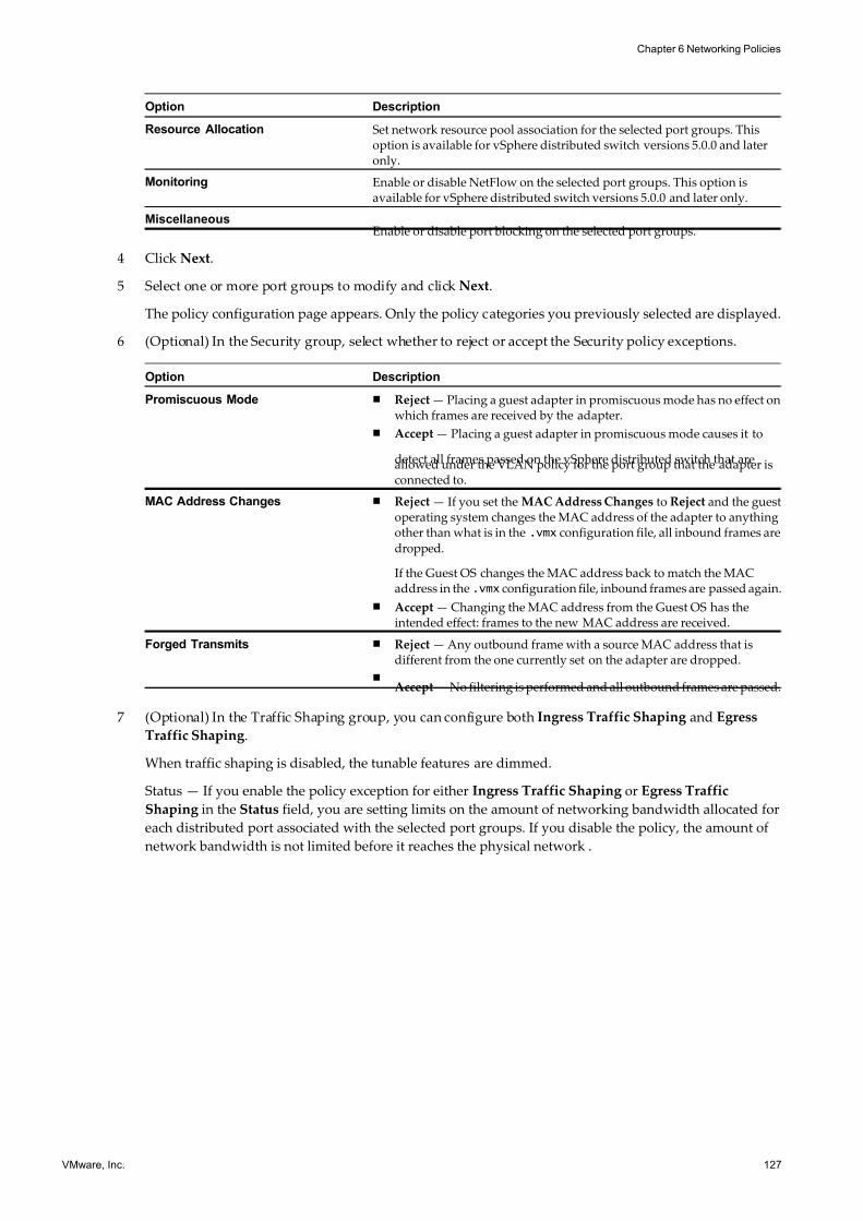
7/15/2019 Vsphere Esxi Vcenter Server 51 Networking Guide
http://slidepdf.com/reader/full/vsphere-esxi-vcenter-server-51-networking-guide-563280a1ebe2b 127/172
Option Description
Resource Allocation Set network resource pool association for the selected port groups. Thisoption is available for vSphere distributed switch versions 5.0.0 and lateronly.
Monitoring Enable or disable NetFlow on the selected port groups. This option isavailable for vSphere distributed switch versions 5.0.0 and later only.
MiscellaneousEnable or disable port blocking on the selected port groups.
4 Click Next.
5 Select one or more port groups to modify and click Next.
The policy configuration page appears. Only the policy categories you previously selected are displayed.
6 (Optional) In the Security group, select whether to reject or accept the Security policy exceptions.
Option Description
Promiscuous Mode n Reject — Placing a guest adapter in promiscuous mode has no effect onwhich frames are received by the adapter.
n Accept — Placing a guest adapter in promiscuous mode causes it to
detect all frames passed on the vSphere distributed switch that areallowed under the VLAN policy for the port group that the adapter isconnected to.
MAC Address Changes n Reject — If you set the MAC Address Changes to Reject and the guestoperating system changes the MAC address of the adapter to anythingother than what is in the .vmx configuration file, all inbound frames are
dropped.
If the Guest OS changes the MAC address back to match the MACaddress in the .vmx configuration file, inbound frames are passed again.
n Accept — Changing the MAC address from the Guest OS has theintended effect: frames to the new MAC address are received.
Forged Transmits n Reject — Any outbound frame with a source MAC address that isdifferent from the one currently set on the adapter are dropped.
nAccept — No filtering is performed and all outbound frames are passed.
7 (Optional) In the Traffic Shaping group, you can configure both Ingress Traffic Shaping and Egress
Traffic Shaping.
When traffic shaping is disabled, the tunable features are dimmed.
Status — If you enable the policy exception for either Ingress Traffic Shaping or Egress Traffic
Shaping in the Status field, you are setting limits on the amount of networking bandwidth allocated for
each distributed port associated with the selected port groups. If you disable the policy, the amount of
network bandwidth is not limited before it reaches the physical network .
Chapter 6 Networking Policies
VMware, Inc. 127
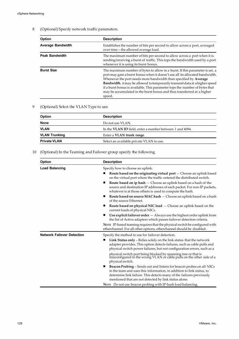
7/15/2019 Vsphere Esxi Vcenter Server 51 Networking Guide
http://slidepdf.com/reader/full/vsphere-esxi-vcenter-server-51-networking-guide-563280a1ebe2b 128/172
8 (Optional) Specify network traffic parameters.
Option Description
Average Bandwidth Establishes the number of bits per second to allow across a port, averagedover time—the allowed average load.
Peak Bandwidth The maximum number of bits per second to allow across a port when it issending/receiving a burst of traffic. This tops the bandwidth used by a portwhenever it is using its burst bonus.
Burst Size The maximum number of bytes to allow in a burst. If this parameter is set, aport may gain a burst bonus when it doesn’t use all its allocated bandwidth.Whenever the port needs more bandwidth than specified by AverageBandwidth , it may be allowed to temporarily transmit data at a higher speedif a burst bonus is available. This parameter tops the number of bytes thatmay be accumulated in the burst bonus and thus transferred at a higherspeed.
9 (Optional) Select the VLAN Type to use.
Option Description
None Do not use VLAN.
VLAN In the VLAN ID field, enter a number between 1 and 4094.
VLAN Trunking Enter a VLAN trunk range.
Private VLAN Select an available private VLAN to use.
10 (Optional) In the Teaming and Failover group specify the following.
Option Description
Load Balancing Specify how to choose an uplink.
n Route based on the originating virtual port — Choose an uplink basedon the virtual port where the traffic entered the distributed switch.
n Route based on ip hash — Choose an uplink based on a hash of thesource and destination IP addresses of each packet. For non-IP packets,whatever is at those offsets is used to compute the hash.
n Route based on source MAC hash — Choose an uplink based on a hashof the source Ethernet.
n Route based on physical NIC load — Choose an uplink based on thecurrent loads of physical NICs.
n Use explicit failover order — Always use the highest order uplink fromthe list of Active adapters which passes failover detection criteria.
NOTE IP-based teaming requires that the physical switch be configured withetherchannel. For all other options, etherchannel should be disabled.
Network Failover Detection Specify the method to use for failover detection.
n Link Status only – Relies solely on the link status that the networkadapter provides. This option detects failures, such as cable pulls andphysical switch power failures, but not configuration errors, such as a
physical switch port being blocked by spanning tree or that ismisconfigured to the wrong VLAN or cable pulls on the other side of aphysical switch.
n Beacon Probing – Sends out and listens for beacon probes on all NICsin the team and uses this information, in addition to link status, todetermine link failure. This detects many of the failures previouslymentioned that are not detected by link status alone.
NOTE Do not use beacon probing with IP-hash load balancing.
vSphere Networking
128 VMware, Inc.
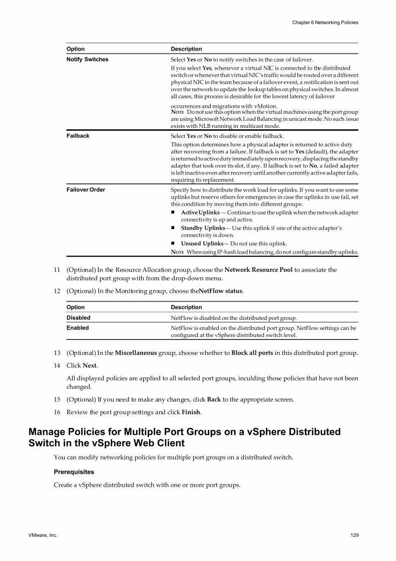
7/15/2019 Vsphere Esxi Vcenter Server 51 Networking Guide
http://slidepdf.com/reader/full/vsphere-esxi-vcenter-server-51-networking-guide-563280a1ebe2b 129/172
Option Description
Notify Switches Select Yes or No to notify switches in the case of failover.
If you select Yes , whenever a virtual NIC is connected to the distributedswitch or whenever that virtual NIC’s traffic would be routed over a differentphysical NIC in the team because of a failover event, a notification is sent outover the network to update the lookup tables on physical switches. In almostall cases, this process is desirable for the lowest latency of failover
occurrences and migrations with vMotion.NOTE Do not use this option when the virtual machines using the port groupare using Microsoft Network Load Balancing in unicast mode. No such issueexists with NLB running in multicast mode.
Failback Select Yes or No to disable or enable failback.
This option determines how a physical adapter is returned to active dutyafter recovering from a failure. If failback is set to Yes (default), the adapteris returned to active duty immediately upon recovery, displacing the standbyadapter that took over its slot, if any. If failback is set to No , a failed adapteris left inactive even after recovery until another currently active adapter fails,requiring its replacement.
Failover Order Specify how to distribute the work load for uplinks. If you want to use someuplinks but reserve others for emergencies in case the uplinks in use fail, setthis condition by moving them into different groups:
n Active Uplinks — Continue to use the uplink when the network adapterconnectivity is up and active.
n Standby Uplinks— Use this uplink if one of the active adapter’sconnectivity is down.
n Unused Uplinks— Do not use this uplink.
NOTE When using IP-hash load balancing, do not configure standby uplinks.
11 (Optional) In the Resource Allocation group, choose the Network Resource Pool to associate the
distributed port group with from the drop-down menu.
12 (Optional) In the Monitoring group, choose theNetFlow status.
Option Description
Disabled NetFlow is disabled on the distributed port group.
Enabled NetFlow is enabled on the distributed port group. NetFlow settings can beconfigured at the vSphere distributed switch level.
13 (Optional) In the Miscellaneous group, choose whether to Block all ports in this distributed port group.
14 Click Next.
All displayed policies are applied to all selected port groups, inculding those policies that have not been
changed.
15 (Optional) If you need to make any changes, click Back to the appropriate screen.
16 Review the port group settings and click Finish.
Manage Policies for Multiple Port Groups on a vSphere DistributedSwitch in the vSphere Web Client
You can modify networking policies for multiple port groups on a distributed switch.
Prerequisites
Create a vSphere distributed switch with one or more port groups.
Chapter 6 Networking Policies
VMware, Inc. 129
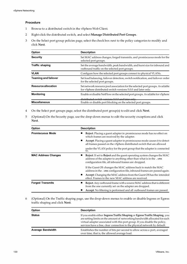
7/15/2019 Vsphere Esxi Vcenter Server 51 Networking Guide
http://slidepdf.com/reader/full/vsphere-esxi-vcenter-server-51-networking-guide-563280a1ebe2b 130/172
Procedure
1 Browse to a distributed switch in the vSphere Web Client.
2 Right-click the distributed switch, and select Manage Distributed Port Groups.
3 On the Select port group policies page, select the check box next to the policy categories to modify and
click Next.
Option Description
Security Set MAC address changes, forged transmits, and promiscuous mode for theselected port groups.
Traffic shaping Set the average bandwidth, peak bandwidth, and burst size for inbound andoutbound traffic on the selected port groups.
VLAN Configure how the selected port groups connect to physical VLANs.
Teaming and failover Set load balancing, failover detection, switch notification, and failover orderfor the selected port groups.
Resource allocation Set network resource pool association for the selected port groups. Availablefor vSphere distributed switch versions 5.0.0 and later only.
Monitoring Enable or disable NetFlow on the selected port groups. Available for vSphere
distributed switch versions 5.0.0 and later only.Miscellaneous Enable or disable port blocking on the selected port groups.
4 On the Select port groups page, select the distributed port group(s) to edit and click Next.
5 (Optional) On the Security page, use the drop-down menus to edit the security exceptions and click
Next.
Option Description
Promiscuous Mode n Reject. Placing a guest adapter in promiscuous mode has no effect onwhich frames are received by the adapter.
n Accept. Placing a guest adapter in promiscuous mode causes it to detectall frames passed on the vSphere distributed switch that are allowed
under the VLAN policy for the port group that the adapter is connectedto.
MAC Address Changes n Reject. If set to Reject and the guest operating system changes the MACaddress of the adapter to anything other than what is in the .vmx
configuration file, all inbound frames are dropped.
If the Guest OS changes the MAC address back to match the MACaddress in the .vmx configuration file, inbound frames are passed again.
n Accept. Changing the MAC address from the Guest OS has the intendedeffect. Frames to the new MAC address are received.
Forged Transmits n Reject. Any outbound frame with a source MAC address that is differentfrom the one currently set on the adapter are dropped.
n Accept. No filtering is performed and all outbound frames are passed.
6 (Optional) On the Traffic shaping page, use the drop-down menus to enable or disable Ingress or Egress
traffic shaping and click Next.
Option Description
Status If you enable either Ingress Traffic Shaping or Egress Traffic Shaping , youare setting limits on the amount of networking bandwidth allocated for eachvirtual adapter associated with this port group. If you disable the policy,services have a free, clear connection to the physical network by default.
Average Bandwidth Establishes the number of bits per second to allow across a port, averagedover time, that is, the allowed average load.
vSphere Networking
130 VMware, Inc.
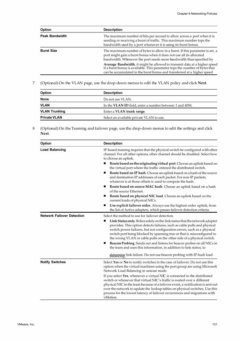
7/15/2019 Vsphere Esxi Vcenter Server 51 Networking Guide
http://slidepdf.com/reader/full/vsphere-esxi-vcenter-server-51-networking-guide-563280a1ebe2b 131/172
Option Description
Peak Bandwidth The maximum number of bits per second to allow across a port when it issending or receiving a burst of traffic. This maximum number tops the bandwidth used by a port whenever it is using its burst bonus.
Burst Size The maximum number of bytes to allow in a burst. If this parameter is set, aport might gain a burst bonus when it does not use all its allocated bandwidth. Whenever the port needs more bandwidth than specified by
Average Bandwidth , it might be allowed to transmit data at a higher speedif a burst bonus is available. This parameter tops the number of bytes thatcan be accumulated in the burst bonus and transferred at a higher speed.
7 (Optional) On the VLAN page, use the drop-down menus to edit the VLAN policy and click Next.
Option Description
None Do not use VLAN.
VLAN In the VLAN ID field, enter a number between 1 and 4094.
VLAN Trunking Enter a VLAN trunk range.
Private VLAN Select an available private VLAN to use.
8 (Optional) On the Teaming and failover page, use the drop-down menus to edit the settings and click
Next.
Option Description
Load Balancing IP-based teaming requires that the physical switch be configured with etherchannel. For all other options, ether channel should be disabled. Select howto choose an uplink.
n Route based on the originating virtual port. Choose an uplink based onthe virtual port where the traffic entered the distributed switch.
n Route based on IP hash. Choose an uplink based on a hash of the sourceand destination IP addresses of each packet. For non-IP packets,whatever is at those offsets is used to compute the hash.
n Route based on source MAC hash. Choose an uplink based on a hash
of the source Ethernet.
n Route based on physical NIC load. Choose an uplink based on thecurrent loads of physical NICs.
n Use explicit failover order. Always use the highest order uplink, fromthe list of Active adapters, which passes failover detection criteria.
Network Failover Detection Select the method to use for failover detection.
n Link Status only. Relies solely on the link status that the network adapterprovides. This option detects failures, such as cable pulls and physicalswitch power failures, but not configuration errors, such as a physicalswitch port being blocked by spanning tree or that is misconfigured tothe wrong VLAN or cable pulls on the other side of a physical switch.
n Beacon Probing. Sends out and listens for beacon probes on all NICs inthe team and uses this information, in addition to link status, to
determine link failure. Do not use beacon probing with IP-hash load balancing.
Notify Switches Select Yes or No to notify switches in the case of failover. Do not use thisoption when the virtual machines using the port group are using MicrosoftNetwork Load Balancing in unicast mode.
If you select Yes , whenever a virtual NIC is connected to the distributedswitch or whenever that virtual NIC’s traffic is routed over a differentphysical NIC in the team because of a failover event, a notification is sent outover the network to update the lookup tables on physical switches. Use thisprocess for the lowest latency of failover occurrences and migrations withvMotion.
Chapter 6 Networking Policies
VMware, Inc. 131
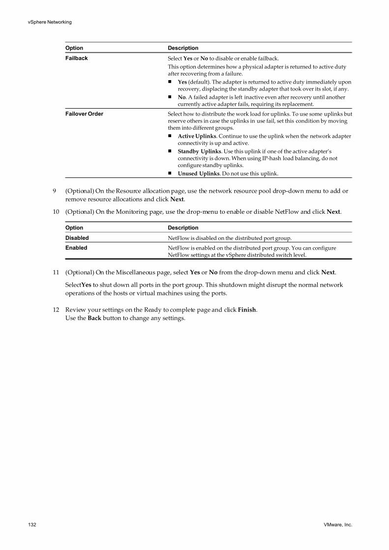
7/15/2019 Vsphere Esxi Vcenter Server 51 Networking Guide
http://slidepdf.com/reader/full/vsphere-esxi-vcenter-server-51-networking-guide-563280a1ebe2b 132/172
Option Description
Failback Select Yes or No to disable or enable failback.
This option determines how a physical adapter is returned to active dutyafter recovering from a failure.
n Yes (default). The adapter is returned to active duty immediately uponrecovery, displacing the standby adapter that took over its slot, if any.
n No. A failed adapter is left inactive even after recovery until anothercurrently active adapter fails, requiring its replacement.
Failover Order Select how to distribute the work load for uplinks. To use some uplinks butreserve others in case the uplinks in use fail, set this condition by movingthem into different groups.
n Active Uplinks. Continue to use the uplink when the network adapterconnectivity is up and active.
n Standby Uplinks. Use this uplink if one of the active adapter’sconnectivity is down. When using IP-hash load balancing, do notconfigure standby uplinks.
n Unused Uplinks. Do not use this uplink.
9 (Optional) On the Resource allocation page, use the network resource pool drop-down menu to add or
remove resource allocations and click Next.
10 (Optional) On the Monitoring page, use the drop-menu to enable or disable NetFlow and click Next.
Option Description
Disabled NetFlow is disabled on the distributed port group.
Enabled NetFlow is enabled on the distributed port group. You can configureNetFlow settings at the vSphere distributed switch level.
11 (Optional) On the Miscellaneous page, select Yes or No from the drop-down menu and click Next.
SelectYes to shut down all ports in the port group. This shutdown might disrupt the normal network
operations of the hosts or virtual machines using the ports.
12 Review your settings on the Ready to complete page and click Finish.
Use the Back button to change any settings.
vSphere Networking
132 VMware, Inc.
7/15/2019 Vsphere Esxi Vcenter Server 51 Networking Guide
http://slidepdf.com/reader/full/vsphere-esxi-vcenter-server-51-networking-guide-563280a1ebe2b 133/172
Advanced Networking 7Advanced networking configuration options allow you greater control over your vSphere networking
environment.
This chapter includes the following topics:
n“Internet Protocol Version 6 (IPv6) Support,” on page 133
n “VLAN Configuration,” on page 134
n “Working With Port Mirroring,” on page 135
n “Configure NetFlow Settings,” on page 145
n “Configure NetFlow Settings with the vSphere Web Client,” on page 146
n “Switch Discovery Protocol,” on page 146
n “Change the DNS and Routing Configuration,” on page 149
n “Change the DNS and Routing Configuration in the vSphere Web Client,” on page 150
n “MAC Addresses,” on page 150
n “Mounting NFS Volumes,” on page 156
n “Network Rollback and Recovery,” on page 157
n “Stateless Network Deployment,” on page 160
Internet Protocol Version 6 (IPv6) Support
Internet Protocol version 6 (IPv6) support in ESXi provides the ability to use Virtual Infrastructure features
such as NFS in an IPv6 environment. Use the Networking Properties dialog box to enable or disable IPv6
support on the host.
IPv6 is designated by the Internet Engineering Task Force as the successor to IPv4. The most obvious difference
is address length. IPv6 uses 128-bit addresses rather than the 32-bit addresses used by IPv4. This increaseresolves the problem of address exhaustion and eliminates the need for network address translation. Other
differences include link-local addresses that appear as the interface is initialized, addresses that are set by
router advertisements, and the ability to have multiple IPv6 addresses on an interface.
In VMware ESXi 5.1, IPv6 is enabled by default.
Prerequisites
Required privilege: Host.Configuration.Network Configuration
VMware, Inc. 133
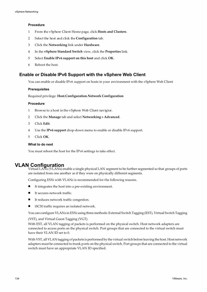
7/15/2019 Vsphere Esxi Vcenter Server 51 Networking Guide
http://slidepdf.com/reader/full/vsphere-esxi-vcenter-server-51-networking-guide-563280a1ebe2b 134/172
Procedure
1 From the vSphere Client Home page, click Hosts and Clusters.
2 Select the host and click the Configuration tab.
3 Click the Networking link under Hardware.
4 In the vSphere Standard Switch view, click the Properties link.
5 Select Enable IPv6 support on this host and click OK.
6 Reboot the host.
Enable or Disable IPv6 Support with the vSphere Web Client
You can enable or disable IPv6 support on hosts in your environment with the vSphere Web Client
Prerequisites
Required privilege: Host.Configuration.Network Configuration
Procedure
1 Browse to a host in the vSphere Web Client navigtor.
2 Click the Manage tab and select Networking > Advanced.
3 Click Edit.
4 Use the IPv6 support drop-down menu to enable or disable IPv6 support.
5 Click OK.
What to do next
You must reboot the host for the IPv6 settings to take effect.
VLAN ConfigurationVirtual LANs (VLANs) enable a single physical LAN segment to be further segmented so that groups of ports
are isolated from one another as if they were on physically different segments.
Configuring ESXi with VLANs is recommended for the following reasons.
n It integrates the host into a pre-existing environment.
n It secures network traffic.
n It reduces network traffic congestion.
n iSCSI traffic requires an isolated network.
You can configure VLANs in ESXi using three methods: External Switch Tagging (EST), Virtual Switch Tagging
(VST), and Virtual Guest Tagging (VGT).
With EST, all VLAN tagging of packets is performed on the physical switch. Host network adapters are
connected to access ports on the physical switch. Port groups that are connected to the virtual switch must
have their VLAN ID set to 0.
With VST, all VLAN tagging of packets is performed by the virtual switch before leaving the host. Host network
adapters must be connected to trunk ports on the physical switch. Port groups that are connected to the virtual
switch must have an appropriate VLAN ID specified.
vSphere Networking
134 VMware, Inc.
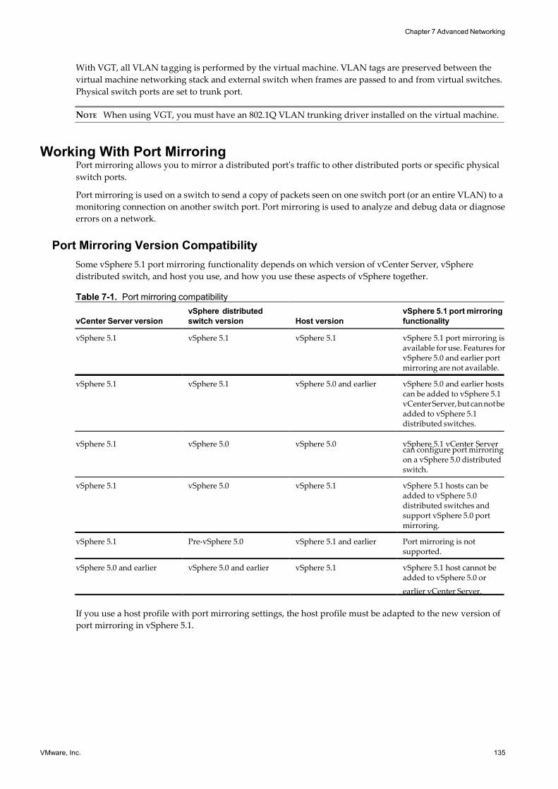
7/15/2019 Vsphere Esxi Vcenter Server 51 Networking Guide
http://slidepdf.com/reader/full/vsphere-esxi-vcenter-server-51-networking-guide-563280a1ebe2b 135/172
With VGT, all VLAN tagging is performed by the virtual machine. VLAN tags are preserved between the
virtual machine networking stack and external switch when frames are passed to and from virtual switches.
Physical switch ports are set to trunk port.
NOTE When using VGT, you must have an 802.1Q VLAN trunking driver installed on the virtual machine.
Working With Port MirroringPort mirroring allows you to mirror a distributed port's traffic to other distributed ports or specific physical
switch ports.
Port mirroring is used on a switch to send a copy of packets seen on one switch port (or an entire VLAN) to a
monitoring connection on another switch port. Port mirroring is used to analyze and debug data or diagnose
errors on a network.
Port Mirroring Version Compatibility
Some vSphere 5.1 port mirroring functionality depends on which version of vCenter Server, vSphere
distributed switch, and host you use, and how you use these aspects of vSphere together.
Table 7-1. Port mirroring compatibility
vCenter Server version
vSphere distributed
switch version Host version
vSphere 5.1 port mirroring
functionality
vSphere 5.1 vSphere 5.1 vSphere 5.1 vSphere 5.1 port mirroring isavailable for use. Features forvSphere 5.0 and earlier portmirroring are not available.
vSphere 5.1 vSphere 5.1 vSphere 5.0 and earlier vSphere 5.0 and earlier hostscan be added to vSphere 5.1vCenter Server, but can not beadded to vSphere 5.1distributed switches.
vSphere 5.1 vSphere 5.0 vSphere 5.0 vSphere 5.1 vCenter Servercan configure port mirroringon a vSphere 5.0 distributedswitch.
vSphere 5.1 vSphere 5.0 vSphere 5.1 vSphere 5.1 hosts can beadded to vSphere 5.0distributed switches andsupport vSphere 5.0 portmirroring.
vSphere 5.1 Pre-vSphere 5.0 vSphere 5.1 and earlier Port mirroring is notsupported.
vSphere 5.0 and earlier vSphere 5.0 and earlier vSphere 5.1 vSphere 5.1 host cannot beadded to vSphere 5.0 or
earlier vCenter Server.
If you use a host profile with port mirroring settings, the host profile must be adapted to the new version of
port mirroring in vSphere 5.1.
Chapter 7 Advanced Networking
VMware, Inc. 135
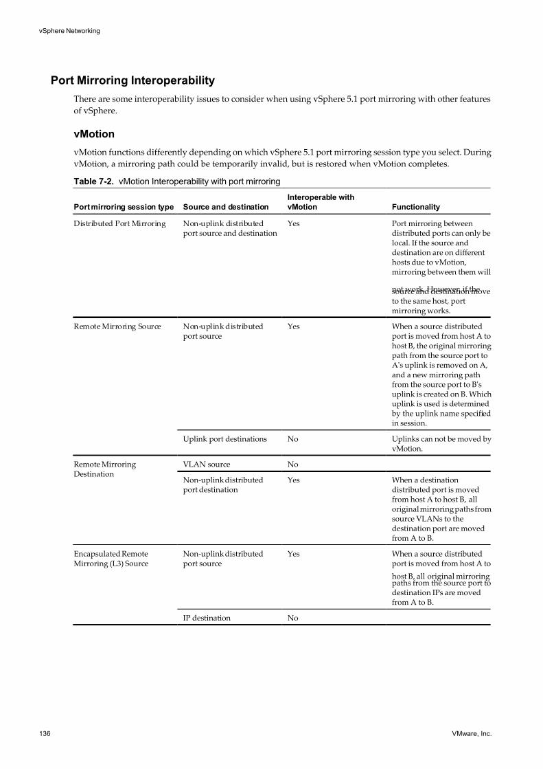
7/15/2019 Vsphere Esxi Vcenter Server 51 Networking Guide
http://slidepdf.com/reader/full/vsphere-esxi-vcenter-server-51-networking-guide-563280a1ebe2b 136/172
Port Mirroring Interoperability
There are some interoperability issues to consider when using vSphere 5.1 port mirroring with other features
of vSphere.
vMotion
vMotion functions differently depending on which vSphere 5.1 port mirroring session type you select. During
vMotion, a mirroring path could be temporarily invalid, but is restored when vMotion completes.
Table 7-2. vMotion Interoperability with port mirroring
Port mirroring session type Source and destination
Interoperable with
vMotion Functionality
Distributed Port Mirroring Non-uplink distributedport source and destination
Yes Port mirroring betweendistributed ports can only belocal. If the source anddestination are on differenthosts due to vMotion,mirroring between them will
not work. However, if thesource and destination moveto the same host, portmirroring works.
Remote Mirroring Source Non-uplink distributedport source
Yes When a source distributedport is moved from host A tohost B, the original mirroringpath from the source port toA's uplink is removed on A,and a new mirroring pathfrom the source port to B'suplink is created on B. Whichuplink is used is determined by the uplink name specifiedin session.
Uplink port destinations No Uplinks can not be moved byvMotion.
Remote MirroringDestination
VLAN source No
Non-uplink distributedport destination
Yes When a destinationdistributed port is movedfrom host A to host B, alloriginal mirroring paths fromsource VLANs to thedestination port are movedfrom A to B.
Encapsulated RemoteMirroring (L3) Source
Non-uplink distributedport source
Yes When a source distributedport is moved from host A to
host B, all original mirroringpaths from the source port todestination IPs are movedfrom A to B.
IP destination No
vSphere Networking
136 VMware, Inc.
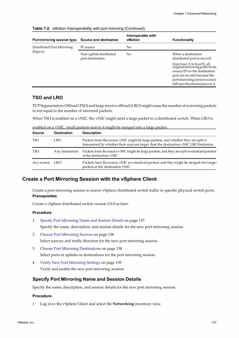
7/15/2019 Vsphere Esxi Vcenter Server 51 Networking Guide
http://slidepdf.com/reader/full/vsphere-esxi-vcenter-server-51-networking-guide-563280a1ebe2b 137/172
Table 7-2. vMotion Interoperability with port mirroring (Continued)
Port mirroring session type Source and destination
Interoperable with
vMotion Functionality
Distributed Port Mirroring(legacy)
IP source No
Non-uplink distributedport destination
No When a destinationdistributed port is moved
from host A to host B, alloriginal mirroring paths fromsource IPs to the destinationport are invalid because theport mirroring session sourcestill sees the destination on A.
TSO and LRO
TCP Segmentation Offload (TSO) and large receive offload (LRO) might cause the number of mirroring packets
to not equal to the number of mirrored packets.
When TSO is enabled on a vNIC, the vNIC might send a large packet to a distributed switch. When LRO is
enabled on a vNIC, small packets sent to it might be merged into a large packet.
Source Destination Description
TSO LRO Packets from the source vNIC might be large packets, and whether they are split isdetermined by whether their sizes are larger than the destination vNIC LRO limitation.
TSO Any destination Packets from the source vNIC might be large packets, and they are split to standard packetsat the destination vNIC.
Any source LRO Packets from the source vNIC are standard packets, and they might be merged into largerpackets at the destination vNIC.
Create a Port Mirroring Session with the vSphere Client
Create a port mirroring session to mirror vSphere distributed switch traffic to specific physical switch ports.
Prerequisites
Create a vSphere distributed switch version 5.0.0 or later.
Procedure
1 Specify Port Mirroring Name and Session Details on page 137
Specify the name, description, and session details for the new port mirroring session.
2 Choose Port Mirroring Sources on page 138
Select sources and traffic direction for the new port mirroring session.
3 Choose Port Mirroring Destinations on page 138
Select ports or uplinks as destinations for the port mirroring session.
4 Verify New Port Mirroring Settings on page 139
Verify and enable the new port mirroring session.
Specify Port Mirroring Name and Session Details
Specify the name, description, and session details for the new port mirroring session.
Procedure
1 Log in to the vSphere Client and select the Networking inventory view.
Chapter 7 Advanced Networking
VMware, Inc. 137
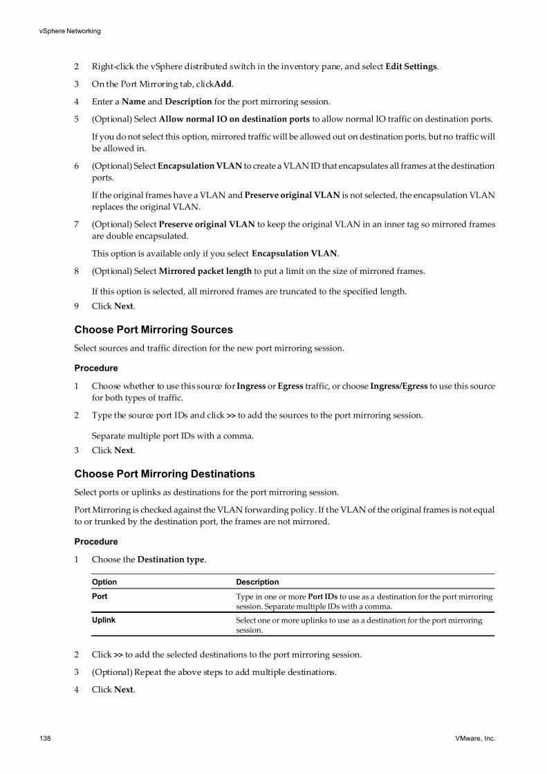
7/15/2019 Vsphere Esxi Vcenter Server 51 Networking Guide
http://slidepdf.com/reader/full/vsphere-esxi-vcenter-server-51-networking-guide-563280a1ebe2b 138/172
2 Right-click the vSphere distributed switch in the inventory pane, and select Edit Settings.
3 On the Port Mirroring tab, clickAdd.
4 Enter a Name and Description for the port mirroring session.
5 (Optional) Select Allow normal IO on destination ports to allow normal IO traffic on destination ports.
If you do not select this option, mirrored traffic will be allowed out on destination ports, but no traffic will
be allowed in.
6 (Optional) Select Encapsulation VLAN to create a VLAN ID that encapsulates all frames at the destination
ports.
If the original frames have a VLAN and Preserve original VLAN is not selected, the encapsulation VLAN
replaces the original VLAN.
7 (Optional) Select Preserve original VLAN to keep the original VLAN in an inner tag so mirrored frames
are double encapsulated.
This option is available only if you select Encapsulation VLAN.
8 (Optional) Select Mirrored packet length to put a limit on the size of mirrored frames.
If this option is selected, all mirrored frames are truncated to the specified length.
9 Click Next.
Choose Port Mirroring Sources
Select sources and traffic direction for the new port mirroring session.
Procedure
1 Choose whether to use this source for Ingress or Egress traffic, or choose Ingress/Egress to use this source
for both types of traffic.
2 Type the source port IDs and click >> to add the sources to the port mirroring session.
Separate multiple port IDs with a comma.
3 Click Next.
Choose Port Mirroring Destinations
Select ports or uplinks as destinations for the port mirroring session.
Port Mirroring is checked against the VLAN forwarding policy. If the VLAN of the original frames is not equal
to or trunked by the destination port, the frames are not mirrored.
Procedure
1 Choose the Destination type.
Option Description
Port Type in one or more Port IDs to use as a destination for the port mirroringsession. Separate multiple IDs with a comma.
Uplink Select one or more uplinks to use as a destination for the port mirroringsession.
2 Click >> to add the selected destinations to the port mirroring session.
3 (Optional) Repeat the above steps to add multiple destinations.
4 Click Next.
vSphere Networking
138 VMware, Inc.
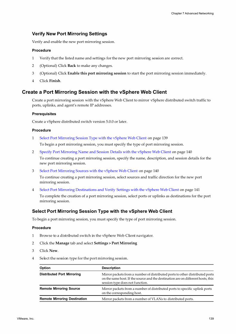
7/15/2019 Vsphere Esxi Vcenter Server 51 Networking Guide
http://slidepdf.com/reader/full/vsphere-esxi-vcenter-server-51-networking-guide-563280a1ebe2b 139/172
Verify New Port Mirroring Settings
Verify and enable the new port mirroring session.
Procedure
1 Verify that the listed name and settings for the new port mirroring session are correct.
2 (Optional) Click Back to make any changes.
3 (Optional) Click Enable this port mirroring session to start the port mirroring session immediately.
4 Click Finish.
Create a Port Mirroring Session with the vSphere Web Client
Create a port mirroring session with the vSphere Web Client to mirror vSphere distributed switch traffic to
ports, uplinks, and agent’s remote IP addresses.
Prerequisites
Create a vSphere distributed switch version 5.0.0 or later.
Procedure
1 Select Port Mirroring Session Type with the vSphere Web Client on page 139
To begin a port mirroring session, you must specify the type of port mirroring session.
2 Specify Port Mirroring Name and Session Details with the vSphere Web Client on page 140
To continue creating a port mirroring session, specify the name, description, and session details for the
new port mirroring session.
3 Select Port Mirroring Sources with the vSphere Web Client on page 140
To continue creating a port mirroring session, select sources and traffic direction for the new port
mirroring session.
4 Select Port Mirroring Destinations and Verify Settings with the vSphere Web Client on page 141
To complete the creation of a port mirroring session, select ports or uplinks as destinations for the port
mirroring session.
Select Port Mirroring Session Type with the vSphere Web Client
To begin a port mirroring session, you must specify the type of port mirroring session.
Procedure
1 Browse to a distributed switch in the vSphere Web Client navigator.
2 Click the Manage tab and select Settings > Port Mirroring
3 Click New.
4 Select the session type for the port mirroring session.
Option Description
Distributed Port Mirroring Mirror packets from a number of distributed ports to other distributed portson the same host. If the source and the destination are on different hosts, thissession type does not function.
Remote Mirroring Source Mirror packets from a number of distributed ports to specific uplink portson the corresponding host.
Remote Mirroring Destination Mirror packets from a number of VLANs to distributed ports.
Chapter 7 Advanced Networking
VMware, Inc. 139
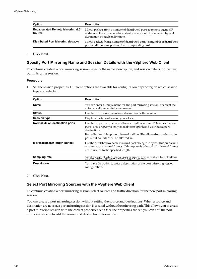
7/15/2019 Vsphere Esxi Vcenter Server 51 Networking Guide
http://slidepdf.com/reader/full/vsphere-esxi-vcenter-server-51-networking-guide-563280a1ebe2b 140/172
Option Description
Encapsulated Remote Mirroring (L3)
Source
Mirror packets from a number of distributed ports to remote agent’s IPaddresses. The virtual machine’s traffic is mirrored to a remote physicaldestination through an IP tunnel.
Distributed Port Mirroring (legacy) Mirror packets from a number of distributed ports to a number of distributedports and/or uplink ports on the corresponding host.
5 Click Next.
Specify Port Mirroring Name and Session Details with the vSphere Web Client
To continue creating a port mirroring session, specify the name, description, and session details for the new
port mirroring session.
Procedure
1 Set the session properties. Different options are available for configuration depending on which session
type you selected.
Option Description
Name You can enter a unique name for the port mirroring session, or accept theautomatically generated session name.
Status Use the drop down menu to enable or disable the session.
Session type Displays the type of session you selected.
Normal I/O on destination ports Use the drop-down menu to allow or disallow normal I/O on destinationports. This property is only available for uplink and distributed portdestinations.
If you disallow this option, mirrored traffic will be allowed out on destinationports, but no traffic will be allowed in.
Mirrored packet length (Bytes) Use the check box to enable mirrored packet length in bytes. This puts a limiton the size of mirrored frames. If this option is selected, all mirrored framesare truncated to the specified length.
Sampling rate Select the rate at which packets are sampled. This is enabled by default forall port mirroring sessions except legacy sessions.
Description You have the option to enter a description of the port mirroring sessionconfiguration.
2 Click Next.
Select Port Mirroring Sources with the vSphere Web Client
To continue creating a port mirroring session, select sources and traffic direction for the new port mirroring
session.
You can create a port mirroring session without setting the source and destinations. When a source and
destination are not set, a port mirroring session is created without the mirroring path. This allows you to create
a port mirroring session with the correct properties set. Once the properties are set, you can edit the port
mirroring session to add the source and destination information.
vSphere Networking
140 VMware, Inc.
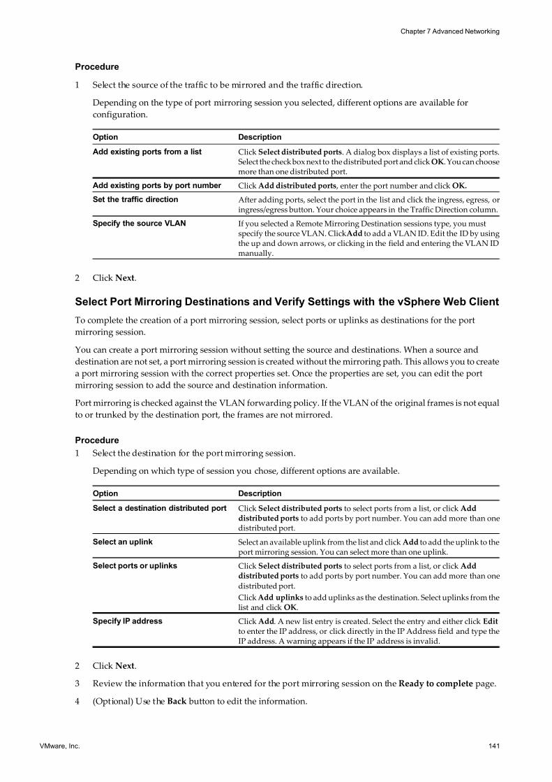
7/15/2019 Vsphere Esxi Vcenter Server 51 Networking Guide
http://slidepdf.com/reader/full/vsphere-esxi-vcenter-server-51-networking-guide-563280a1ebe2b 141/172
Procedure
1 Select the source of the traffic to be mirrored and the traffic direction.
Depending on the type of port mirroring session you selected, different options are available for
configuration.
Option Description
Add existing ports from a list Click Select distributed ports. A dialog box displays a list of existing ports.Select the check box next to the distributed port and click OK. You can choosemore than one distributed port.
Add existing ports by port number Click Add distributed ports , enter the port number and click OK.
Set the traffic direction After adding ports, select the port in the list and click the ingress, egress, oringress/egress button. Your choice appears in the Traffic Direction column.
Specify the source VLAN If you selected a Remote Mirroring Destination sessions type, you mustspecify the source VLAN. ClickAdd to add a VLAN ID. Edit the ID by usingthe up and down arrows, or clicking in the field and entering the VLAN IDmanually.
2 Click Next.
Select Port Mirroring Destinations and Verify Settings with the vSphere Web Client
To complete the creation of a port mirroring session, select ports or uplinks as destinations for the port
mirroring session.
You can create a port mirroring session without setting the source and destinations. When a source and
destination are not set, a port mirroring session is created without the mirroring path. This allows you to create
a port mirroring session with the correct properties set. Once the properties are set, you can edit the port
mirroring session to add the source and destination information.
Port mirroring is checked against the VLAN forwarding policy. If the VLAN of the original frames is not equal
to or trunked by the destination port, the frames are not mirrored.
Procedure
1 Select the destination for the port mirroring session.
Depending on which type of session you chose, different options are available.
Option Description
Select a destination distributed port Click Select distributed ports to select ports from a list, or click Adddistributed ports to add ports by port number. You can add more than onedistributed port.
Select an uplink Select an available uplink from the list and click Add to add the uplink to theport mirroring session. You can select more than one uplink.
Select ports or uplinks Click Select distributed ports to select ports from a list, or click Adddistributed ports to add ports by port number. You can add more than one
distributed port.
Click Add uplinks to add uplinks as the destination. Select uplinks from thelist and click OK.
Specify IP address Click Add. A new list entry is created. Select the entry and either click Editto enter the IP address, or click directly in the IP Address field and type theIP address. A warning appears if the IP address is invalid.
2 Click Next.
3 Review the information that you entered for the port mirroring session on the Ready to complete page.
4 (Optional) Use the Back button to edit the information.
Chapter 7 Advanced Networking
VMware, Inc. 141
7/15/2019 Vsphere Esxi Vcenter Server 51 Networking Guide
http://slidepdf.com/reader/full/vsphere-esxi-vcenter-server-51-networking-guide-563280a1ebe2b 142/172
5 Click Finish.
The new port mirroring session appears in the Port Mirroring section of the Settings tab.
View Port Mirroring Session Details
View port mirroring session details, including status, sources, and destinations.
Procedure
1 Log in to the vSphere Client and select the Networking inventory view.
2 Right-click the vSphere distributed switch in the inventory pane, and select Edit Settings.
3 On the Port Mirroring tab, select the port mirroring session to view.
Details for the selected port mirroring session appear under Port Mirroring Session Details.
4 (Optional) Click Edit to edit the details for the selected port mirroring session.
5 (Optional) Click Delete to delete the selected port mirroring session.
6 (Optional) Click Add to add a new port mirroring session.
View Port Mirroring Session Details in the vSphere Web Client
View port mirroring session details, including status, sources, and destinations.
Procedure
1 Browse to a distributed switch in the vSphere Web Client navigator.
2 On the Manage tab click Settings > Port Mirroring.
3 Select a port mirroring session from the list to display more detailed information at the bottom of the
screen. Use the tabs to review configuration details.
4 (Optional) Click New to add a new port mirroring session.
5 (Optional) Click Edit to edit the details for the selected port mirroring session.
6 (Optional) Click Remove to delete the selected port mirroring session.
Edit Port Mirroring Name and Session Details
Edit the details of a port mirroring session, including name, description, and status.
Procedure
1 Log in to the vSphere Client and select the Networking inventory view.
2 Right-click the vSphere distributed switch in the inventory pane, and select Edit Settings.
3 On the Port Mirroring tab, select the port mirroring session to modify and click Edit.4 Click the Properties tab.
5 (Optional) Type a new Name for the port mirroring session.
6 (Optional) Type a new Description for the port mirroring session.
7 Select whether the port mirroring session should be Enabledor Disabled.
8 (Optional) Select Allow normal IO on destination ports to allow normal IO traffic on destination ports.
If you do not select this option, mirrored traffic is allowed out on destination ports, but no traffic is allowed
in.
vSphere Networking
142 VMware, Inc.
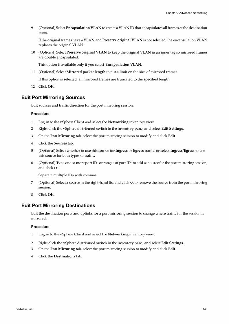
7/15/2019 Vsphere Esxi Vcenter Server 51 Networking Guide
http://slidepdf.com/reader/full/vsphere-esxi-vcenter-server-51-networking-guide-563280a1ebe2b 143/172
9 (Optional) Select Encapsulation VLAN to create a VLAN ID that encapsulates all frames at the destination
ports.
If the original frames have a VLAN and Preserve original VLAN is not selected, the encapsulation VLAN
replaces the original VLAN.
10 (Optional) Select Preserve original VLAN to keep the original VLAN in an inner tag so mirrored frames
are double encapsulated.
This option is available only if you select Encapsulation VLAN.
11 (Optional) Select Mirrored packet length to put a limit on the size of mirrored frames.
If this option is selected, all mirrored frames are truncated to the specified length.
12 Click OK.
Edit Port Mirroring Sources
Edit sources and traffic direction for the port mirroring session.
Procedure
1 Log in to the vSphere Client and select the Networking inventory view.
2 Right-click the vSphere distributed switch in the inventory pane, and select Edit Settings.
3 On the Port Mirroring tab, select the port mirroring session to modify and click Edit.
4 Click the Sources tab.
5 (Optional) Select whether to use this source for Ingress or Egress traffic, or select Ingress/Egress to use
this source for both types of traffic.
6 (Optional) Type one or more port IDs or ranges of port IDs to add as source for the port mirroring session,
and click >>.
Separate multiple IDs with commas.
7 (Optional) Select a source in the right-hand list and click << to remove the source from the port mirroring
session.
8 Click OK.
Edit Port Mirroring Destinations
Edit the destination ports and uplinks for a port mirroring session to change where traffic for the session is
mirrored.
Procedure
1 Log in to the vSphere Client and select the Networking inventory view.
2 Right-click the vSphere distributed switch in the inventory pane, and select Edit Settings.
3 On the Port Mirroring tab, select the port mirroring session to modify and click Edit.
4 Click the Destinations tab.
Chapter 7 Advanced Networking
VMware, Inc. 143
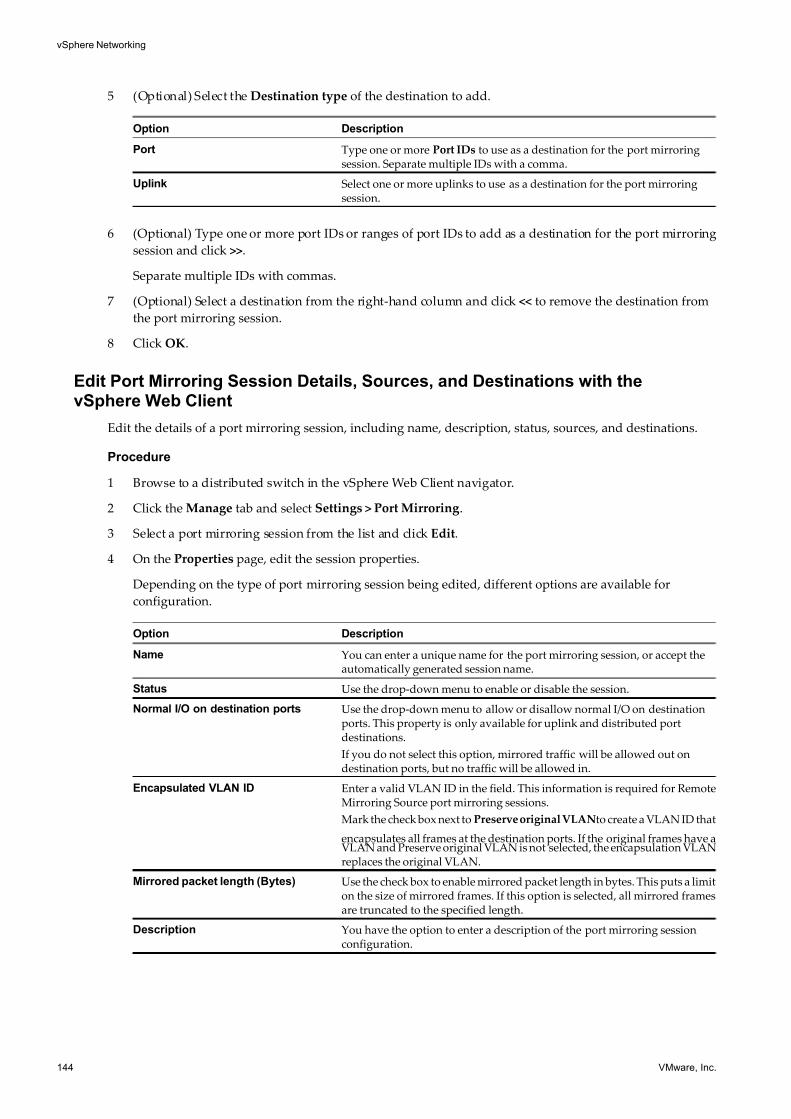
7/15/2019 Vsphere Esxi Vcenter Server 51 Networking Guide
http://slidepdf.com/reader/full/vsphere-esxi-vcenter-server-51-networking-guide-563280a1ebe2b 144/172
5 (Optional) Select the Destination type of the destination to add.
Option Description
Port Type one or more Port IDs to use as a destination for the port mirroringsession. Separate multiple IDs with a comma.
Uplink Select one or more uplinks to use as a destination for the port mirroringsession.
6 (Optional) Type one or more port IDs or ranges of port IDs to add as a destination for the port mirroring
session and click >>.
Separate multiple IDs with commas.
7 (Optional) Select a destination from the right-hand column and click << to remove the destination from
the port mirroring session.
8 Click OK.
Edit Port Mirroring Session Details, Sources, and Destinations with thevSphere Web Client
Edit the details of a port mirroring session, including name, description, status, sources, and destinations.
Procedure
1 Browse to a distributed switch in the vSphere Web Client navigator.
2 Click the Manage tab and select Settings > Port Mirroring.
3 Select a port mirroring session from the list and click Edit.
4 On the Properties page, edit the session properties.
Depending on the type of port mirroring session being edited, different options are available for
configuration.
Option Description
Name You can enter a unique name for the port mirroring session, or accept theautomatically generated session name.
Status Use the drop-down menu to enable or disable the session.
Normal I/O on destination ports Use the drop-down menu to allow or disallow normal I/O on destinationports. This property is only available for uplink and distributed portdestinations.
If you do not select this option, mirrored traffic will be allowed out ondestination ports, but no traffic will be allowed in.
Encapsulated VLAN ID Enter a valid VLAN ID in the field. This information is required for RemoteMirroring Source port mirroring sessions.
Mark the check box next to Preserve original VLANto create a VLAN ID that
encapsulates all frames at the destination ports. If the original frames have aVLAN and Preserve original VLAN is not selected, the encapsulation VLANreplaces the original VLAN.
Mirrored packet length (Bytes) Use the check box to enable mirrored packet length in bytes. This puts a limiton the size of mirrored frames. If this option is selected, all mirrored framesare truncated to the specified length.
Description You have the option to enter a description of the port mirroring sessionconfiguration.
vSphere Networking
144 VMware, Inc.
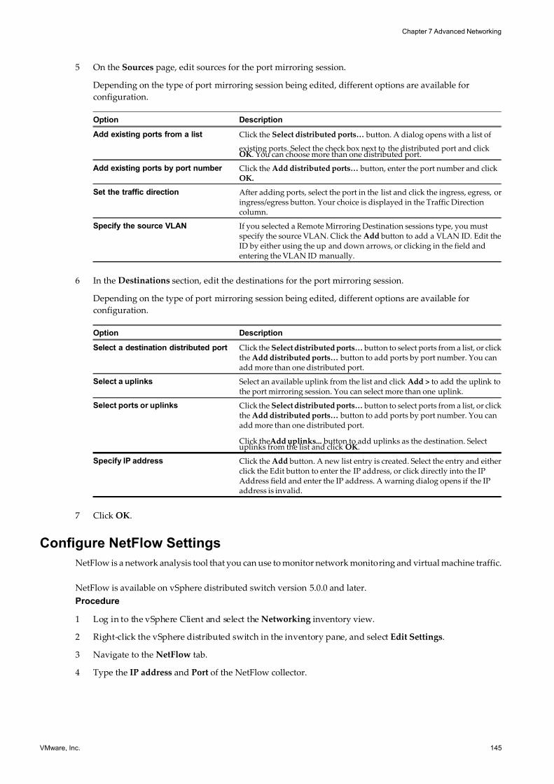
7/15/2019 Vsphere Esxi Vcenter Server 51 Networking Guide
http://slidepdf.com/reader/full/vsphere-esxi-vcenter-server-51-networking-guide-563280a1ebe2b 145/172
5 On the Sources page, edit sources for the port mirroring session.
Depending on the type of port mirroring session being edited, different options are available for
configuration.
Option Description
Add existing ports from a list Click the Select distributed ports… button. A dialog opens with a list of
existing ports. Select the check box next to the distributed port and clickOK. You can choose more than one distributed port.
Add existing ports by port number Click the Add distributed ports… button, enter the port number and clickOK.
Set the traffic direction After adding ports, select the port in the list and click the ingress, egress, oringress/egress button. Your choice is displayed in the Traffic Directioncolumn.
Specify the source VLAN If you selected a Remote Mirroring Destination sessions type, you mustspecify the source VLAN. Click the Add button to add a VLAN ID. Edit theID by either using the up and down arrows, or clicking in the field andentering the VLAN ID manually.
6 In the Destinations section, edit the destinations for the port mirroring session.
Depending on the type of port mirroring session being edited, different options are available for
configuration.
Option Description
Select a destination distributed port Click the Select distributed ports… button to select ports from a list, or clickthe Add distributed ports… button to add ports by port number. You canadd more than one distributed port.
Select a uplinks Select an available uplink from the list and click Add > to add the uplink tothe port mirroring session. You can select more than one uplink.
Select ports or uplinks Click the Select distributed ports… button to select ports from a list, or clickthe Add distributed ports… button to add ports by port number. You canadd more than one distributed port.
Click theAdd uplinks... button to add uplinks as the destination. Selectuplinks from the list and click OK.
Specify IP address Click the Add button. A new list entry is created. Select the entry and eitherclick the Edit button to enter the IP address, or click directly into the IPAddress field and enter the IP address. A warning dialog opens if the IPaddress is invalid.
7 Click OK.
Configure NetFlow Settings
NetFlow is a network analysis tool that you can use to monitor network monitoring and virtual machine traffic.
NetFlow is available on vSphere distributed switch version 5.0.0 and later.
Procedure
1 Log in to the vSphere Client and select the Networking inventory view.
2 Right-click the vSphere distributed switch in the inventory pane, and select Edit Settings.
3 Navigate to the NetFlow tab.
4 Type the IP address and Port of the NetFlow collector.
Chapter 7 Advanced Networking
VMware, Inc. 145
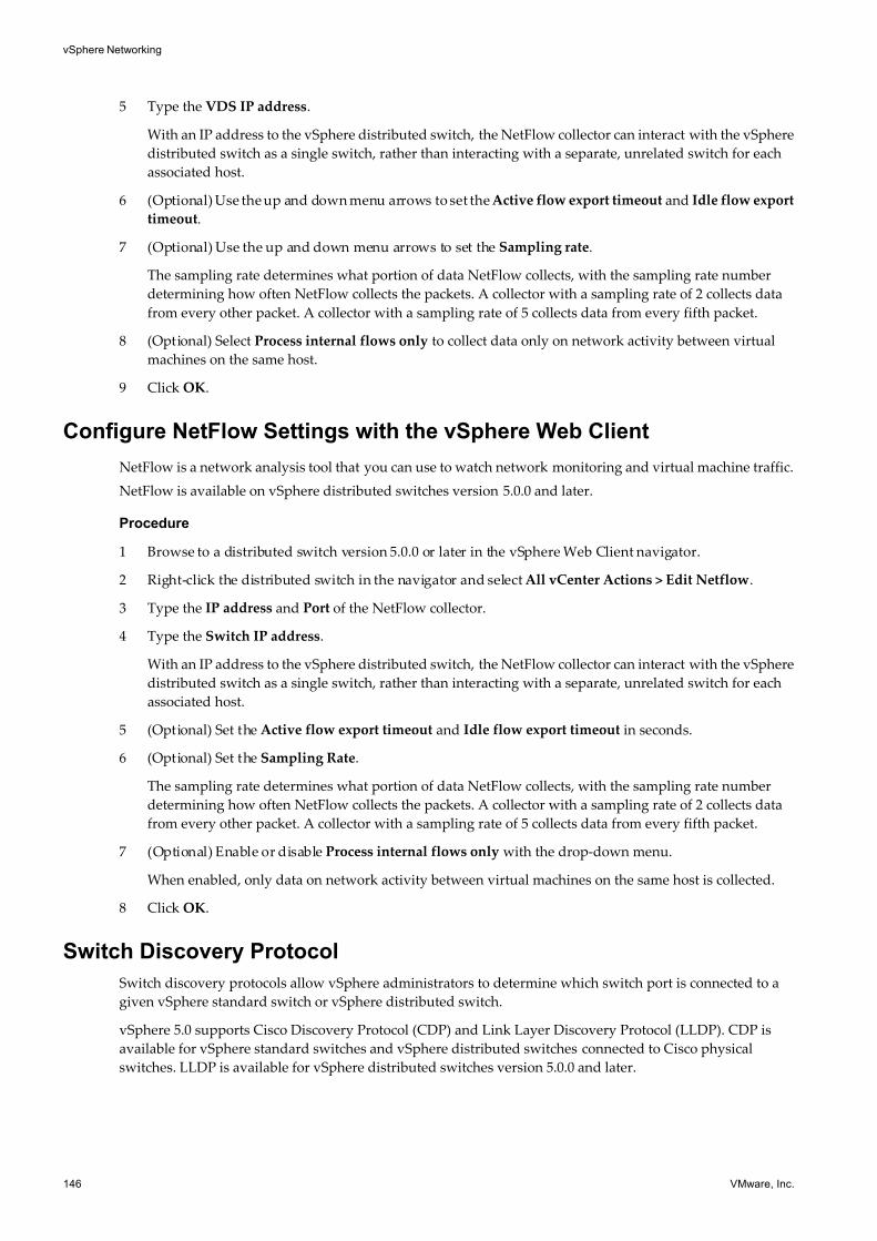
7/15/2019 Vsphere Esxi Vcenter Server 51 Networking Guide
http://slidepdf.com/reader/full/vsphere-esxi-vcenter-server-51-networking-guide-563280a1ebe2b 146/172
5 Type the VDS IP address.
With an IP address to the vSphere distributed switch, the NetFlow collector can interact with the vSphere
distributed switch as a single switch, rather than interacting with a separate, unrelated switch for each
associated host.
6 (Optional) Use the up and down menu arrows to set the Active flow export timeout and Idle flow export
timeout.
7 (Optional) Use the up and down menu arrows to set the Sampling rate.
The sampling rate determines what portion of data NetFlow collects, with the sampling rate number
determining how often NetFlow collects the packets. A collector with a sampling rate of 2 collects data
from every other packet. A collector with a sampling rate of 5 collects data from every fifth packet.
8 (Optional) Select Process internal flows only to collect data only on network activity between virtual
machines on the same host.
9 Click OK.
Configure NetFlow Settings with the vSphere Web Client
NetFlow is a network analysis tool that you can use to watch network monitoring and virtual machine traffic.
NetFlow is available on vSphere distributed switches version 5.0.0 and later.
Procedure
1 Browse to a distributed switch version 5.0.0 or later in the vSphere Web Client navigator.
2 Right-click the distributed switch in the navigator and select All vCenter Actions > Edit Netflow.
3 Type the IP address and Port of the NetFlow collector.
4 Type the Switch IP address.
With an IP address to the vSphere distributed switch, the NetFlow collector can interact with the vSphere
distributed switch as a single switch, rather than interacting with a separate, unrelated switch for each
associated host.
5 (Optional) Set the Active flow export timeout and Idle flow export timeout in seconds.
6 (Optional) Set the Sampling Rate.
The sampling rate determines what portion of data NetFlow collects, with the sampling rate number
determining how often NetFlow collects the packets. A collector with a sampling rate of 2 collects data
from every other packet. A collector with a sampling rate of 5 collects data from every fifth packet.
7 (Optional) Enable or disable Process internal flows only with the drop-down menu.
When enabled, only data on network activity between virtual machines on the same host is collected.
8 Click OK.
Switch Discovery Protocol
Switch discovery protocols allow vSphere administrators to determine which switch port is connected to a
given vSphere standard switch or vSphere distributed switch.
vSphere 5.0 supports Cisco Discovery Protocol (CDP) and Link Layer Discovery Protocol (LLDP). CDP is
available for vSphere standard switches and vSphere distributed switches connected to Cisco physical
switches. LLDP is available for vSphere distributed switches version 5.0.0 and later.
vSphere Networking
146 VMware, Inc.
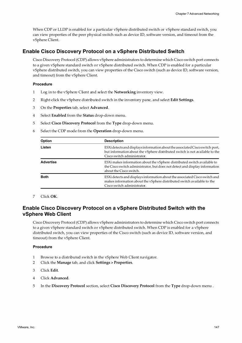
7/15/2019 Vsphere Esxi Vcenter Server 51 Networking Guide
http://slidepdf.com/reader/full/vsphere-esxi-vcenter-server-51-networking-guide-563280a1ebe2b 147/172
When CDP or LLDP is enabled for a particular vSphere distributed switch or vSphere standard switch, you
can view properties of the peer physical switch such as device ID, software version, and timeout from the
vSphere Client.
Enable Cisco Discovery Protocol on a vSphere Distributed Switch
Cisco Discovery Protocol (CDP) allows vSphere administrators to determine which Cisco switch port connects
to a given vSphere standard switch or vSphere distributed switch. When CDP is enabled for a particular
vSphere distributed switch, you can view properties of the Cisco switch (such as device ID, software version,
and timeout) from the vSphere Client.
Procedure
1 Log in to the vSphere Client and select the Networking inventory view.
2 Right-click the vSphere distributed switch in the inventory pane, and select Edit Settings.
3 On the Properties tab, select Advanced.
4 Select Enabled from the Status drop-down menu.
5 Select Cisco Discovery Protocol from the Type drop-down menu.
6 Select the CDP mode from the Operation drop-down menu.
Option Description
Listen ESXi detects and displays information about the associated Cisco switch port, but information about the vSphere distributed switch is not available to theCisco switch administrator.
Advertise ESXi makes information about the vSphere distributed switch available tothe Cisco switch administrator, but does not detect and display informationabout the Cisco switch.
Both ESXi detects and displays information about the associated Cisco switch andmakes information about the vSphere distributed switch available to theCisco switch administrator.
7 Click OK.
Enable Cisco Discovery Protocol on a vSphere Distributed Switch with thevSphere Web Client
Cisco Discovery Protocol (CDP) allows vSphere administrators to determine which Cisco switch port connects
to a given vSphere standard switch or vSphere distributed switch. When CDP is enabled for a vSphere
distributed switch, you can view properties of the Cisco switch (such as device ID, software version, and
timeout) from the vSphere Client.
Procedure
1 Browse to a distributed switch in the vSphere Web Client navigator.
2 Click the Manage tab, and click Settings > Properties.
3 Click Edit.
4 Click Advanced.
5 In the Discovery Protocol section, select Cisco Discovery Protocol from the Type drop-down menu .
Chapter 7 Advanced Networking
VMware, Inc. 147
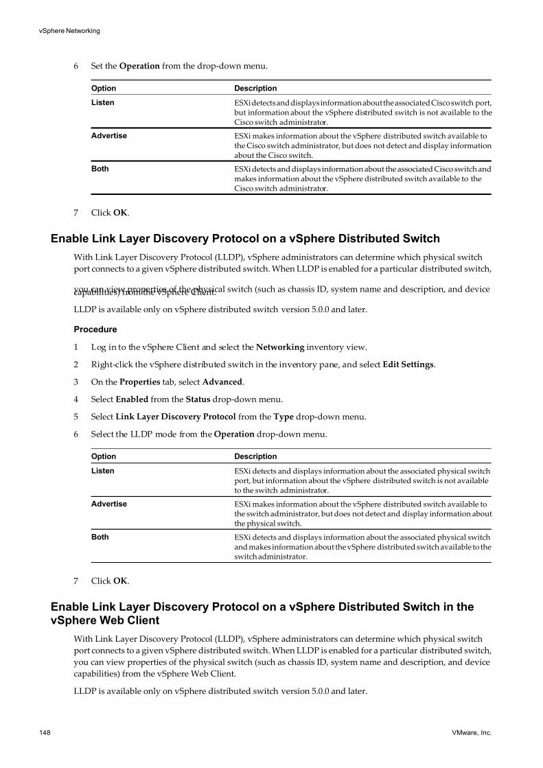
7/15/2019 Vsphere Esxi Vcenter Server 51 Networking Guide
http://slidepdf.com/reader/full/vsphere-esxi-vcenter-server-51-networking-guide-563280a1ebe2b 148/172
6 Set the Operation from the drop-down menu.
Option Description
Listen ESXi detects and displays information about the associated Cisco switch port, but information about the vSphere distributed switch is not available to theCisco switch administrator.
Advertise ESXi makes information about the vSphere distributed switch available tothe Cisco switch administrator, but does not detect and display informationabout the Cisco switch.
Both ESXi detects and displays information about the associated Cisco switch andmakes information about the vSphere distributed switch available to theCisco switch administrator.
7 Click OK.
Enable Link Layer Discovery Protocol on a vSphere Distributed Switch
With Link Layer Discovery Protocol (LLDP), vSphere administrators can determine which physical switch
port connects to a given vSphere distributed switch. When LLDP is enabled for a particular distributed switch,
you can view properties of the physical switch (such as chassis ID, system name and description, and devicecapabilities) from the vSphere Client.
LLDP is available only on vSphere distributed switch version 5.0.0 and later.
Procedure
1 Log in to the vSphere Client and select the Networking inventory view.
2 Right-click the vSphere distributed switch in the inventory pane, and select Edit Settings.
3 On the Properties tab, select Advanced.
4 Select Enabled from the Status drop-down menu.
5 Select Link Layer Discovery Protocol from the Type drop-down menu.
6 Select the LLDP mode from the Operation drop-down menu.
Option Description
Listen ESXi detects and displays information about the associated physical switchport, but information about the vSphere distributed switch is not availableto the switch administrator.
Advertise ESXi makes information about the vSphere distributed switch available tothe switch administrator, but does not detect and display information aboutthe physical switch.
Both ESXi detects and displays information about the associated physical switchand makes information about the vSphere distributed switch available to theswitch administrator.
7 Click OK.
Enable Link Layer Discovery Protocol on a vSphere Distributed Switch in thevSphere Web Client
With Link Layer Discovery Protocol (LLDP), vSphere administrators can determine which physical switch
port connects to a given vSphere distributed switch. When LLDP is enabled for a particular distributed switch,
you can view properties of the physical switch (such as chassis ID, system name and description, and device
capabilities) from the vSphere Web Client.
LLDP is available only on vSphere distributed switch version 5.0.0 and later.
vSphere Networking
148 VMware, Inc.
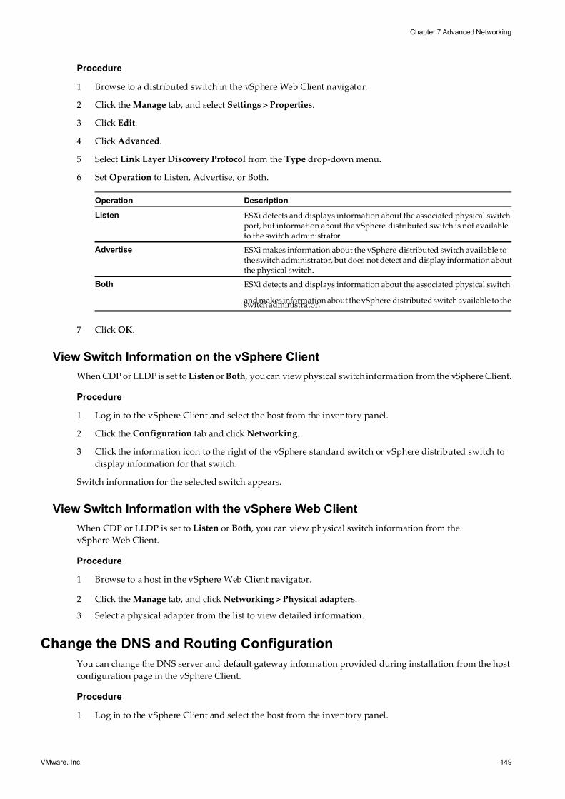
7/15/2019 Vsphere Esxi Vcenter Server 51 Networking Guide
http://slidepdf.com/reader/full/vsphere-esxi-vcenter-server-51-networking-guide-563280a1ebe2b 149/172
Procedure
1 Browse to a distributed switch in the vSphere Web Client navigator.
2 Click the Manage tab, and select Settings > Properties.
3 Click Edit.
4 Click Advanced.
5 Select Link Layer Discovery Protocol from the Type drop-down menu.
6 Set Operation to Listen, Advertise, or Both.
Operation Description
Listen ESXi detects and displays information about the associated physical switchport, but information about the vSphere distributed switch is not availableto the switch administrator.
Advertise ESXi makes information about the vSphere distributed switch available tothe switch administrator, but does not detect and display information aboutthe physical switch.
Both ESXi detects and displays information about the associated physical switch
and makes information about the vSphere distributed switch available to theswitch administrator.
7 Click OK.
View Switch Information on the vSphere Client
When CDP or LLDP is set to Listen or Both , you can view physical switch information from the vSphere Client.
Procedure
1 Log in to the vSphere Client and select the host from the inventory panel.
2 Click the Configuration tab and click Networking.
3 Click the information icon to the right of the vSphere standard switch or vSphere distributed switch to
display information for that switch.
Switch information for the selected switch appears.
View Switch Information with the vSphere Web Client
When CDP or LLDP is set to Listen or Both , you can view physical switch information from the
vSphere Web Client.
Procedure
1 Browse to a host in the vSphere Web Client navigator.
2 Click the Manage tab, and click Networking > Physical adapters.
3 Select a physical adapter from the list to view detailed information.
Change the DNS and Routing Configuration
You can change the DNS server and default gateway information provided during installation from the host
configuration page in the vSphere Client.
Procedure
1 Log in to the vSphere Client and select the host from the inventory panel.
Chapter 7 Advanced Networking
VMware, Inc. 149
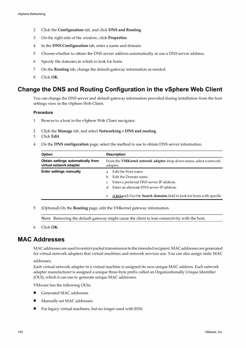
7/15/2019 Vsphere Esxi Vcenter Server 51 Networking Guide
http://slidepdf.com/reader/full/vsphere-esxi-vcenter-server-51-networking-guide-563280a1ebe2b 150/172
2 Click the Configuration tab, and click DNS and Routing.
3 On the right side of the window, click Properties.
4 In the DNS Configuration tab, enter a name and domain.
5 Choose whether to obtain the DNS server address automatically or use a DNS server address.
6 Specify the domains in which to look for hosts.
7 On the Routing tab, change the default gateway information as needed.
8 Click OK.
Change the DNS and Routing Configuration in the vSphere Web Client
You can change the DNS server and default gateway information provided during installation from the host
settings view in the vSphere Web Client.
Procedure
1 Browse to a host in the vSphere Web Client navigator.
2 Click the Manage tab, and select Networking > DNS and routing.
3 Click Edit.
4 On the DNS configuration page, select the method to use to obtain DNS server information.
Option Description
Obtain settings automatically from
virtual network adapter
From the VMKernel network adapter drop-down menu, select a networkadapter.
Enter settings manually a Edit the Host name.
b Edit the Domain name.
c Enter a preferred DNS server IP address.
d Enter an alternate DNS server IP address.
e (Optional) Use the Search domains field to look for hosts with specificnames.
5 (Optional) On the Routing page, edit the VMkernel gateway information.
NOTE Removing the default gateway might cause the client to lose connectivity with the host.
6 Click OK.
MAC Addresses
MAC addresses are used to restrict packet transmission to the intended recipient. MAC addresses are generated
for virtual network adapters that virtual machines and network services use. You can also assign static MAC
addresses.
Each virtual network adapter in a virtual machine is assigned its own unique MAC address. Each network
adapter manufacturer is assigned a unique three-byte prefix called an Organizationally Unique Identifier
(OUI), which it can use to generate unique MAC addresses.
VMware has the following OUIs:
n Generated MAC addresses
n Manually set MAC addresses
n For legacy virtual machines, but no longer used with ESXi
vSphere Networking
150 VMware, Inc.
7/15/2019 Vsphere Esxi Vcenter Server 51 Networking Guide
http://slidepdf.com/reader/full/vsphere-esxi-vcenter-server-51-networking-guide-563280a1ebe2b 151/172
MAC Address Generation
MAC addresses are used to restrict packet transmission to the intended recipient. Each virtual network adapter
in a virtual machine is assigned its own unique MAC address.
The following options are for MAC address generation:
n VMware OUI allocation - default allocation
n Prefix-based allocation
n Range-based allocation
After the MAC address is generated, it does not change unless the virtual machine has MAC address collision
with another registered virtual machine. The MAC address is saved in the configuration file of the virtual
machine. All MAC addresses that have been assigned to network adapters of running and suspended virtual
machines on a given physical machine are tracked.
If you use invalid prefix- or range-based allocation values, an error is logged in the vpxd.log file and vCenter
Server will not allocate MAC addresses during a virtual machine provisioning.
VMware OUI AllocationVMware Organizationally Unique Identifier (OUI) allocation uses the default OUI 00:50:56 as the first three
bytes of the MAC address generated for each virtual network. The MAC address-generation algorithm
produces the rest of the MAC address. The algorithm guarantees unique MAC addresses within a virtual
machine and attempts to provide unique MAC addresses across virtual machines.
VMware OUI allocation is set as the default MAC address generation schema for virtual machines.
The VMware Universally Unique Identifier (UUID) generates MAC addresses that are checked for conflicts.
The generated MAC addresses are created by using three parts: the VMware OUI, the SMBIOS UUID for the
physical ESXi machine, and a hash based on the name of the entity that the MAC address is being generated
for. All MAC addresses that have been assigned to network adapters of running and suspended virtual
machines on a given physical machine are tracked.
The MAC address of a powered off virtual machine is not checked against those of running or suspended
virtual machines. It is possible that when a virtual machine is powered on again, it can acquire a different MAC
address. This acquisition is caused by a conflict with a virtual machine that was powered on when this virtual
machine was powered off.
However, if you reconfigure the powered off virtual machine's vNIC, for example by updating the vNIC MAC
address allocation type, or specifying a static MAC address, vCenter Server resolves any MAC address conflict
before the vNIC reconfiguration takes effect.
Prefix-Based MAC Address Allocation
Prefix-based allocation allows you to specify an OUI other than the VMware default 00:50:56. This scheme is
supported on ESXi hosts 5.1 and later.
You can also choose to use a Locally Administered Address (LAA) instead of OUI, which increases the range
of MAC addresses. The MAC address-generation algorithm produces the rest of the MAC address. The
algorithm guarantees unique MAC addresses within a machine and attempts to provide unique MAC
addresses across machines.
When using prefix-based allocation, you must provide unique prefixes for different vCenter Server instances.
vCenter Server relies on different prefixes to avoid MAC address duplication issues.
Chapter 7 Advanced Networking
VMware, Inc. 151
7/15/2019 Vsphere Esxi Vcenter Server 51 Networking Guide
http://slidepdf.com/reader/full/vsphere-esxi-vcenter-server-51-networking-guide-563280a1ebe2b 152/172
Range-Based MAC Address Allocation
Range-based allocation allows you to specify OUI-based Locally Administered Address (LAA) ranges that can
be set to include or exclude specific ranges. You specify one or more ranges using a minimum starting point
and a maximum ending point, such as (005068000002, 0050680000ff). MAC addresses are generated only from
within the specified range.
This scheme is supported on ESXi hosts 5.1 and later.
You can specify multiple sets of LAA ranges. The number of MAC addresses in use are tracked for each range
that is defined. MAC addresses are allocated from the first defined range set that still has addresses available.
After MAC addresses are allocated, the information is recorded in the vCenter Server database. This allows
vCenter Server to check for MAC address collision within the ranges assigned to that vCenter Server.
When using range-based allocation, you must provide different instances of vCenter Server with ranges that
do not overlap. vCenter Server does not detect ranges that might conflict with ranges used by other
vCenter Server instances.
Assign a Generated MAC Address
You use the vSphere Client or the vSphere Web Client to adjust existing prefix-based or range-basedparameters.
If you are changing from one type of allocation to another, for example changing from the VMware OUI
allocation to a range-based allocation, use the vSphere Client or the vSphere We b Client. However, when a
schema is prefix-based or range-based and you want to change to a different allocation schema, you must edit
the vpxd.cfd file manually and restart vCenter Server.
Add or Adjust Range- or Prefixed-Based Allocations in the vSphere Client
If you use a range- or prefixed-based allocation, you can use the vSphere Client to adjust the parameters of
your allocation.
To change allocation schemes from VMware OUI to a range- or prefixed-based allocation, you must add a key
and default value to Advanced Settings. If you already added the key and default values, use AdvancedSettings to adjust the parameters for each key.
To change from a range- or prefixed-based allocation to the VMware OUI allocation, you cannot use the
vSphere Client. You must edit the vpxd.cfg file manually. VMware recommends changing allocation types
through the vSphere Client because editing files can introduce errors. For information about editing the
vpxd.cfg file, see “Set or Change Allocation Type,” on page 154.
CAUTION Prefix-based MAC address allocation is only supported invCenter Server 5.1 and 5.1 hosts. If you
add pre-5.1 hosts to vCenter Server 5.1 , and use anything other than VMware OUI prefix-based MAC address
allocation, virtual machines assigned non-VMware OUI prefixed MAC addresses fail to power on their pre-5.1
hosts.
The prefix-based MAC address allocation schemes are not supported on pre-5.1 hosts because pre-5.1 hostsexplicitly validate if an assigned MAC address uses the VMware OUI 00:50:56 prefix. If the MAC address is
not prefixed with 00:50:56, the virtual machine pre-5.1 host fails to power on.
Procedure
1 In the vSphere Client, select Administration > Server Settings.
2 Select Advanced Settings.
vSphere Networking
152 VMware, Inc.
7/15/2019 Vsphere Esxi Vcenter Server 51 Networking Guide
http://slidepdf.com/reader/full/vsphere-esxi-vcenter-server-51-networking-guide-563280a1ebe2b 153/172
3 Add or adjust one of the following allocation types.
NOTE Use only one allocation type.
u Prefix-based allocation
Key Default Value
config.vpxd.macAllocScheme.prefixScheme.prefix 005026
config.vpxd.macAllocScheme.prefixScheme.prefixLength 23
Change the default values to your choice of prefix and prefix length.
u Range-based allocation
Key Default Value
config.vpxd.macAllocScheme.rangeScheme.range[0].begin 005067000000
config.vpxd.macAllocScheme.rangeScheme.range[0].end 005067ffffff
Change the default values to the allocation range of your choice. Replace [0] with the range ID of your
choice.
4 Click OK.
Add or Adjust Existing Range- or Prefixed-Based Allocations in thevSphere Web Client
If you are changing allocations from VMware OUI to a range- or prefixed-based allocation, you can use the
vSphere Web Client to change allocations or adjust the parameters of your allocation.
To change allocation schemes from VMware OUI to a range- or prefixed-based allocation, you must add a key
and default value to Advanced Settings. If you already added the key and default values, use Advanced
Settings to adjust the parameters for each key.
To change from a range- or prefixed-based allocation to the VMware OUI allocation, you cannot use the
vSphere Web Client and must edit the vpxd.cfg file manually. VMware recommends changing allocation typesthrough the vSphere Web Clientbecause editing files manually can introduce errors. For information about
editing the vpxd.cfg file, see “Set or Change Allocation Type,” on page 154.
CAUTION Prefix- and range-based MAC address allocation is only supported invCenter Server 5.1 and 5.1
hosts. If you add pre-5.1 hosts to vCenter Server 5.1 , and use anything other than VMware OUI prefix- or
range-based MAC address allocation, virtual machines assigned non-VMware OUI prefixed MAC addresses
fail to power on their pre-5.1 hosts.
The prefix- and range-based MAC address allocation schemes are not supported on pre-5.1 hosts because
pre-5.1 hosts explicitly validate if an assigned MAC address uses the VMware OUI 00:50:56 prefix. If the MAC
address is not prefixed with 00:50:56, the virtual machine pre-5.1 host fails to power on.
Procedure
1 Browse to a vCenter Serverin the vSphere Web Client.
2 Click the Manage tab and select Settings > Advanced Settinges.
3 Click Edit.
Chapter 7 Advanced Networking
VMware, Inc. 153
7/15/2019 Vsphere Esxi Vcenter Server 51 Networking Guide
http://slidepdf.com/reader/full/vsphere-esxi-vcenter-server-51-networking-guide-563280a1ebe2b 154/172
4 Add or adjust one of the following allocation types.
NOTE Use only one allocation type.
u Prefix-based allocation
Key Default Value
config.vpxd.macAllocScheme.prefixScheme.prefix 005026
config.vpxd.macAllocScheme.prefixScheme.prefixLength 23
Change the default values to your choice of prefix and prefix length.
u Range-based allocation
Key Default Value
config.vpxd.macAllocScheme.rangeScheme.range[0].begin 005067000000
config.vpxd.macAllocScheme.rangeScheme.range[0].end 005067ffffff
Change the default values to the allocation range of your choice. Replace [0] with the range ID of your
choice.
5 Click OK.
Set or Change Allocation Type
If you are changing from range- or prefixed-based allocation to the VMware OUI allocation, you must set the
allocation type in the vpxd.cfd file and restart the vCenter Server.
Prerequisites
Decide on an allocation type before changing the vpxd.cfg. For information on allocation types, see “MAC
Address Generation,” on page 151
Procedure
1 On the host machine for your vCenter Server, navigate to …\VMware\VMware VirtualCenter.
2 Open the vpxd.cfg file.
3 Decide on an allocation type to use and enter the corresponding XML code in the file to configure the
allocation type.
The following are examples of XML code to use.
NOTE Use only one allocation type.
u VMware OUI allocation
<vpxd>
<macAllocScheme><VMwareOUI>true</VMwareOUI>
</macAllocScheme>
</vpxd>
u Prefix-based allocation
<vpxd>
<macAllocScheme>
<prefixScheme>
<prefix>005026</prefix>
vSphere Networking
154 VMware, Inc.
7/15/2019 Vsphere Esxi Vcenter Server 51 Networking Guide
http://slidepdf.com/reader/full/vsphere-esxi-vcenter-server-51-networking-guide-563280a1ebe2b 155/172
<prefixLength>23</prefixLength>
</prefixScheme>
</macAllocScheme>
</vpxd>
u Range-based allocation
<vpxd>
<macAllocScheme>
<rangeScheme>
<range id="0">
<begin>005067000001</begin>
<end>005067ffffff</end>
</range>
</rangeScheme>
</macAllocScheme>
</vpxd>
4 Save the vpxd.cfg.
5 Restart the vCenter Server host.
Static MAC Addresses
In most network deployments, generated MAC addresses are appropriate. However, you might need to set a
static MAC address for a virtual network adapter.
The following examples show when you might set a static MAC address.
n Virtual network adapters on different physical hosts share the same subnet and are assigned the same
MAC address, causing a conflict.
n You want to ensure that a virtual network adapter always has the same MAC address.
By default, VMware uses the Organizationally Unique Identifier (OUI) 00:50:56 for manually generated
addresses, but all unique manually generated addresses are supported.
NOTE If you choose to use the VMware OUI, part of the range has been partitioned for use by
vCenter Server , host physical NICs, virtual NICs, and future use.
You can set a static MAC address using the VMware OUI prefix by adding the following line to a virtual
machine‘s configuration file:
ethernet<number>.address = 00:50:56:XX:YY:ZZ
In the example, <number> refers to the number of the Ethernet adapter, XX is a valid hexadecimal number
between 00 and 3F, and YY and ZZ are valid hexadecimal numbers between 00 and FF. The value for XX cannot
be greater than 3F to avoid conflict with MAC addresses that are generated by the VMware Workstation and
VMware Server products. The maximum value for a manually generated MAC address is shown in the sample.
ethernet<number>.address = 00:50:56:3F:FF:FF
You must also set the address type in a virtual machine’s configuration file.
ethernet<number>.addressType="static"
Because ESXi virtual machines do not support arbitrary MAC addresses, you must use the example format.
Choose a unique value for XX:YY:ZZ among your hard-coded addresses to avoid conflicts between the
automatically assigned MAC addresses and the manually assigned ones.
Chapter 7 Advanced Networking
VMware, Inc. 155
7/15/2019 Vsphere Esxi Vcenter Server 51 Networking Guide
http://slidepdf.com/reader/full/vsphere-esxi-vcenter-server-51-networking-guide-563280a1ebe2b 156/172
It is your responsibility to to ensure that no other non-VMware devices use addresses assigned to VMware
components. For example, you might have physical servers in the same subnet, which use 11:11:11:11:11:11,
22:22:22:22:22:22 as static MAC addresses. Since the physical servers do not belong to the vCenter Server
inventory, vCenter Server is not able to check for address collision.
Assign a static MAC Address in the vSphere Client
You can assign static MAC addresses to a powered-down virtual machine's virtual NICs.
Procedure
1 Log in to the vSphere Client and select the virtual machine from the inventory panel.
2 Click the Summary tab and click Edit Settings.
3 Select the network adapter from the Hardware list.
4 In the MAC Address group, select Manual.
5 Enter the static MAC address, and click OK.
Assign a Static MAC Address with the vSphere Web Client
You can assign static MAC addresses to a powered-down virtual machine's virtual NICs.
Prerequisites
Power down the virtual machine before assigning a static MAC address.
Procedure
1 Locate a virtual machine in the vSphere Web Client.
a To locate a virtual machine, select a datacenter, folder, cluster, resource pool, or host and click the
Related Objects tab.
b Click Virtual Machines and select a virtual machine from the list.
2 On the Manage tab, select Settings > VM Hardware.
3 Click Edit.
4 On the Virtual Hardware tab, expand the network adapter section.
5 In the MAC Address section, select Manual from the drop-down menu.
6 Type the static MAC address and click OK.
Mounting NFS Volumes
ESXi supports VMkernel-based NFS mounts for storing virtual disks on NFS datastores.
In addition to storing virtual disks on NFS datastores, you can also use NFS Datastores as a central repository
for ISO images and virtual machine templates. For more information about creating NFS datastores, see vSphere
Storage.
ESXi supports NFS version 3 over Layer 2 and Layer 3 Network switches. Host servers and NFS storage arrays
must be on different subnets and the network switch must handle the routing information.
vSphere Networking
156 VMware, Inc.
7/15/2019 Vsphere Esxi Vcenter Server 51 Networking Guide
http://slidepdf.com/reader/full/vsphere-esxi-vcenter-server-51-networking-guide-563280a1ebe2b 157/172
Network Rollback and Recovery
vSphere 5.1 and later allows you to rollback and recover from network misconfiguration using save
configuration files or previous version of configurations.
vSphere 5.1 allows you to rollback to previous networking configurations if a networking misconfiguration
occurs. vSphere 5.1 also allows you to recover from any misconfiguration by connecting directly to a host tofix any networking issues through the DCUI. Rollback is available for use on both standard and distributed
switches.
vSphere Network Rollback
Use rollback to prevent accidental misconfiguration of management networking and loss of connectivity to
the host by rolling back to a previous valid configuration.
In vSphere 5.1, rollback is enabled by default. However, you can enable or disable rollbacks at the
vCenter Server level.
Several networking events can trigger a rollback. The events are grouped into the following categories:
n Host networking rollbacks (virtual switches or network system)
n Distributed switch rollbacks
Host Networking Rollbacks
Host networking rollbacks occur when an invalid change is made to the host networking configuration. Every
network change that disconnects a host also triggers a rollback. The following changes to the host networking
configuration are examples of what might trigger a rollback:
n Updating the speed or duplex of a physical NIC.
n Updating DNS and routing settings.
n Updating teaming and failover policies or traffic shaping policies of a standard port group that contains
the management VMkernel network adapter.
n Updating the VLAN of a standard port group that contains the management VMkernel network adapter.
n Increasing the MTU of management VMkernel network adapters and its switch to values not supported
by the physical infrastructure.
n Changing the IP settings of management VMkernel network adapters.
n Removing the management VMkernel network adapter from a standard or distributed switch.
n Removing a physical NIC of a standard or distributed switch containing the management VMkernel
network adapter.
If a network disconnects for any of these reasons, the task fails and the host reverts to the last valid
configuration.
Distributed Switch Rollbacks
Distributed switch rollbacks occur when invalid updates are made to distributed switch-related objects, such
as distributed switches, distributed port groups, or distributed ports. The following changes to the distributed
switch configuration might trigger a rollback:
n Changing the MTU of a distributed switch.
n Changing the following settings in the distributed port group of the management VMkernel network
adapter:
n Teaming and failover
Chapter 7 Advanced Networking
VMware, Inc. 157
7/15/2019 Vsphere Esxi Vcenter Server 51 Networking Guide
http://slidepdf.com/reader/full/vsphere-esxi-vcenter-server-51-networking-guide-563280a1ebe2b 158/172
n VLAN
n Traffic shaping
n Blocking all ports in the distributed port group containing the management VMkernel network adapter.
n Overriding the policies above for the distributed port the management VMkernel network adapter is
connected to
If an invalid configuration for any of the changes occurs, one or more hosts might be out of synchronization
with the distributed switch.
If you know where the conflicting configuration setting is located, you can manually correct the setting. For
example, if you migrated a management VMkernel network adapter to a new VLAN incorrectly, the VLAN
might not be trucked on the physical switch. When you correct the physical switch configuration, the next
distributed switch-to-host synchronization will resolve the configuration issue.
If you are not sure where the problem exists, you can rollback the distributed switch or distributed port group
to a previous configuration. You perform both of these steps manually.
Rollback to a Previous Configuration with the vSphere Web Client
You can rollback most networking objects to a previous configuration.
Procedure
1 In the vSphere Web Client, navigate to the affected networking object, such as a distributed switch, or
distributed port group.
2 Right-click the affected network object in the navaigator and select All vCenter Actions > Restore
Configuration.
3 (Optional) If you are restoring the configuration of a distributed switch:
a Click Browse to navigate to the location of a distributed switch backup file.
b Select Restore distributed switch and all port groups or Restore distribued switch only.
c Click Next.
4 (Optional) If you are restoring the configuration of a distributed port group or uplink group:
a Select Restore to previous configuration or Restore configuration from a file.
b If restoriong from a file, click Browse to navigate to the location of a distributed port group backup
file.
c Click Next.
5 Review the configuration information and click Finish.
You can also revert to a saved networking configuration. This option is available only for distributed switches.
See “Export, Import, and Restore Distributed Switch Configurations,” on page 40.
Disable Network Rollback Using the vSphere Web Client
Use rollback to prevent accidental misconfiguration of management networking and loss of connectivity to
the host. Rollback is enabled by default in vSphere 5.1 and later. You can disable rollback using the
vSphere Web Client.
Procedure
1 Browse to a vCenter Server in the vSphere Web Client navigator.
2 Click the Manage tab, and select Settings..
3 Select Advanced Settings and click Edit.
vSphere Networking
158 VMware, Inc.
7/15/2019 Vsphere Esxi Vcenter Server 51 Networking Guide
http://slidepdf.com/reader/full/vsphere-esxi-vcenter-server-51-networking-guide-563280a1ebe2b 159/172
4 Select the config.vpxd.network.rollbackkey, and change the value to false.
If the key is not present, you can add it and set the value to false.
5 Click OK.
Disable Network Rollback Using the Configuration File
Use rollback to prevent accidental misconfiguration of management networking and loss of connectivity tothe host. Rollback is enabled by default in vSphere 5.1 and later. You can disable rollback by editing the
vpxd.cfg file.
Procedure
1 Navigate to …VMware\VMware VirtualCenter on the host where you are disabling network rollback.
2 Open the vpxd.cfg file.
3 Add the following XML to the file to disable network rollback:
<config>
<vpxd>
<network>
<rollback>false</rollback>
</network>
</vpxd>
</config>
4 Save and close the file.
Recover From Network Configuration Errors
vSphere 5.1 and later allows you to connect directly to a host to fix distributed switch properties or other
networking misconfigurations using the Direct Console User Interface (DCUI).
Recovery is not supported on stateless ESXi instances.
For more information on accessing and using the DCUI, see the vSphere Security documentation.
Prerequisites
The Management Network must be configured on a distributed switch. This is the only way you can fix
distributed switch configuration errors using the DCUI.
Procedure
1 Connect to the DCUI.
2 From the Network Restore Options menu, select Restore vDS.
3 Type the correct values for VLAN uplink and blocked properties, where appropriate.
4 Press Enter.
The DCUI clones a host local port from the existing misconfigured port and applies the values you provided
for VLAN and Blocked. The DCUI changes the Management Network to use the new host local port to restore
connectivity to vCenter Server. vCenter Server picks up the new host local port and updates its database with
the new information. vCenter Server creates a standalone port that is connected to the Management Network.
Chapter 7 Advanced Networking
VMware, Inc. 159
7/15/2019 Vsphere Esxi Vcenter Server 51 Networking Guide
http://slidepdf.com/reader/full/vsphere-esxi-vcenter-server-51-networking-guide-563280a1ebe2b 160/172
Stateless Network Deployment
Stateless is a mode of execution for ESXi hosts with no local storage that formerly would save configuration
or state. Configurations are abstracted into a host profile, which is a template that applies to a class of machines.
Stateless allows easy replacement, removal, and addition of failed hardware, and improves the ease of scaling
a hardware deployment.
Every stateless ESXi boot is like a first boot. The ESXi host boots with networking connectivity to
vCenter Server through the built-in standard switch. If the host profile specifies distributed switch
membership, vCenter Server joins the ESXi host to VMware distributed switches or a third party switch
solution.
When planning the network setup for stateless ESXi hosts, you should keep the configuration as generic as
possible and avoid host-specific items. Currently the design has no hooks to reconfigure physical switches
when deploying a new host. Any such requirement would need special handling.
To set up stateless deployment, one ESXi host must be installed in the standard fashion. Then find and record
the following network-related information to save in the host profile:
n vSphere standard switch instances and settings (port groups, uplinks, MTU, and so forth)
n Distributed switch instances (VMware and third party)
n Selection rules for uplinks and uplink port or port groups
n vNIC information:
n Address information (IPv4 or IPv6, static or DHCP, gateway)
n Port groups and distributed port groups assigned to the physical network adapter (vmknic)
n If there are distributed switches, record VLAN, physical NICs bound to the vmknic , and if
Etherchannel is configured
The recorded information is used as a template for the host profile. Once the host profile virtual switch
information has been extracted and placed in the host profile, you have the opportunity to change any of the
information. Modifications are offered for both standard and distributed switches in these sections: uplink
selection policy, based on either vmnic name or device number, and auto discovery based on VLAN ID. The
(possibly modified) information is stored by the stateless boot infrastructure and applied to a stateless ESXi
host on its next boot. During network initialization, a generic network plug-in interprets the recorded host
profile setting and does the following:
n Loads appropriate physical NIC drivers.
n Creates all standard switch instances, along with port groups. It selects uplinks based on policy. If the
policy is based on the VLAN ID, there is a probing process to gather relevant information.
n For VMkernel network adapters connected to the standard switch, it creates VMkernel network adapters
and connects them to port groups.
n For each VMkernel network adapter connected to a distributed switch, it creates a temporary standardswitch (as needed) with uplinks bound to the VMkernel network adapter. It creates a temporary port
group with VLAN and teaming policies based on recorded information. Specifically, IP-hash is used if
Etherchannel was used in the distributed switch.
n Configures all VMkernel network adapter settings (assigns address, gateway, MTU, and so forth).
Basic connectivity is functioning, and the networking setup is complete if there is no distributed switch present.
vSphere Networking
160 VMware, Inc.
7/15/2019 Vsphere Esxi Vcenter Server 51 Networking Guide
http://slidepdf.com/reader/full/vsphere-esxi-vcenter-server-51-networking-guide-563280a1ebe2b 161/172
If there is a distributed switch present, the system stays in maintenance mode until distributed switch
remediation is complete. No virtual machines are started at this time. Because distributed switches requires
vCenter Server, the boot process continues until vCenter Server connectivity is established, and
vCenter Server notices that the host should be part of a distributed switch. It issues a distributed switch host
join, creating a distributed switch proxy standard switch on the host, selects appropriate uplinks, and migrates
the vmknic from the standard switch to the distributed switch. When this operation is complete, it deletes the
temporary standard switch and port groups.
At the end of the remediation process, the ESXi host is taken out of maintenance mode, and HA or DRS can
start virtual machines on the host.
In the absence of a host profile, a temporary standard switch is created with “default networking” logic, which
creates a management network switch (with no VLAN tag) whose uplink corresponds to the PXE booting
vNIC. A vmknic is created on the management network port group with the same MAC address as the PXE
booting vNIC. This logic was previously used for PXE booting. If there is a host profile, but the networking
host profile is disabled or fatally incomplete, vCenter Server falls back to default networking so that the
ESXi host can be managed remotely. This triggers a compliance failure, so vCenter Server then initiates recovery
actions.
Chapter 7 Advanced Networking
VMware, Inc. 161

7/15/2019 Vsphere Esxi Vcenter Server 51 Networking Guide
http://slidepdf.com/reader/full/vsphere-esxi-vcenter-server-51-networking-guide-563280a1ebe2b 162/172
vSphere Networking
162 VMware, Inc.
7/15/2019 Vsphere Esxi Vcenter Server 51 Networking Guide
http://slidepdf.com/reader/full/vsphere-esxi-vcenter-server-51-networking-guide-563280a1ebe2b 163/172
Networking Best Practices 8Consider these best practices when you configure your network.
n Separate network services from one another to achieve greater security and better performance.
Put a set of virtual machines on a separate physical NIC. This separation allows for a portion of the total
networking workload to be shared evenly across multiple CPUs. The isolated virtual machines can then better serve traffic from a Web client, for example
n Keep the vMotion connection on a separate network devoted to vMotion. When migration with vMotion
occurs, the contents of the guest operating system’s memory is transmitted over the network. You can do
this either by using VLANs to segment a single physical network or by using separate physical networks
(the latter is preferable).
n When using passthrough devices with a Linux kernel version 2.6.20 or earlier, avoid MSI and MSI-X modes
because these modes have significant performance impact.
n To physically separate network services and to dedicate a particular set of NICs to a specific network
service, create a vSphere standard switch or vSphere distributed switch for each service. If this is not
possible, separate network services on a single switch by attaching them to port groups with different
VLAN IDs. In either case, confirm with your network administrator that the networks or VLANs youchoose are isolated in the rest of your environment and that no routers connect them.
n You can add and remove network adapters from a standard or distributed switch without affecting the
virtual machines or the network service that is running behind that switch. If you remove all the running
hardware, the virtual machines can still communicate among themselves. If you leave one network adapter
intact, all the virtual machines can still connect with the physical network.
n To protect your most sensitive virtual machines, deploy firewalls in virtual machines that route between
virtual networks with uplinks to physical networks and pure virtual networks with no uplinks.
n For best performance, use vmxnet3 virtual NICs.
n Every physical network adapter connected to the same vSphere standard switch or vSphere distributed
switch should also be connected to the same physical network.
n Configure all VMkernel network adapters to the same MTU. When several VMkernel network adapters
are connected to vSphere distributed switches but have different MTUs configured, you might experience
network connectivity problems.
n When creating a distributed port group, do not use dynamic binding. Dynamic binding is deprecated in
ESXi 5.0.
n
VMware, Inc. 163

7/15/2019 Vsphere Esxi Vcenter Server 51 Networking Guide
http://slidepdf.com/reader/full/vsphere-esxi-vcenter-server-51-networking-guide-563280a1ebe2b 164/172
vSphere Networking
164 VMware, Inc.
7/15/2019 Vsphere Esxi Vcenter Server 51 Networking Guide
http://slidepdf.com/reader/full/vsphere-esxi-vcenter-server-51-networking-guide-563280a1ebe2b 165/172
Index
A
active adapters 24
active uplinks 95, 97, 101
adding
distributed port groups 42
distributed switch 33
vSphere distributed switch 28, 33
adding a VMkernel networ k adapter 18
adjust MAC address allocation parameters 152,
153
admin contact info 31
average bandwidth, standard switch 116
Bbandwidth
average 114, 116
peak 114, 116
beacon probing, standard switches 92, 93
binding on host, distributed port groups 47
block all ports
distributed port groups 125
distributed ports 126
blocked ports
distributed port groups 125, 126, 129
distributed ports 125
burst size, standard switch 116
CCDP
distributed switch 55
physical network adapter 55
uplink port 55
Cisco Discovery Protocol 31, 147, 149
Cisco switches 10, 146
config reset at disconnect, distributed port
groups 47
D
DCUI 157, 159
default gateway, editing 58
delete resource pool, vSphere distributed
switch 72
Direct Console User Interface (DCUI) 157, 159
DirectPath I/O
enable 81
virtual machine 81
vMotion 81
DirectPath I/O Gen. 2 81
disable rollback 158
disable rollback with vpxd.cfg 159
distributed port
edit name 51
edit settings 51
monitoring port state 50
port state 50
Security policy 113
traffic shaping policy 120
VLAN policies 107
distributed port groupconnect to a virtual machine 65
network resource pool 71
traffic shaping policy 118
distributed port groups
add new 42
adding 42
Advanced settings 47
average bandwidth 118, 126, 129
binding on host 47
block all ports 125
blocked ports 125, 126, 129
burst size 118, 126, 129
config reset at disconnect 47
description 45
export configuration 40, 47, 48
failover order 98, 100, 126, 129
failover policies 98, 100, 126, 129
forged transmits 111, 126, 129
general settings 46
import configuration 40, 47, 48
Layer 2 security policy 112
live port moving 47
load balancing 98, 126, 129MAC address changes 111, 126, 129
miscellaneous policies 125, 126, 129
Miscellaneous policy 125
Monitoring Policy 123
name 45
NetFlow 42, 123, 126, 129
NetFlow policy 123
Network I/O Control 121, 126, 129
network resource pool 42, 46
network resource pools 121, 126, 129
VMware, Inc. 165
7/15/2019 Vsphere Esxi Vcenter Server 51 Networking Guide
http://slidepdf.com/reader/full/vsphere-esxi-vcenter-server-51-networking-guide-563280a1ebe2b 166/172
notify switches 98, 126, 129
number of ports 45
override port policies 47
override settings 47
peak bandwidth 118, 126, 129
port allocation 42, 46
port binding 42, 46port blocking 42
port group type 45
port name format 47
port policies 125, 126, 129
promiscuous mode 111, 126, 129
PVLAN 105, 126, 129
QOS policies 105, 126, 129
reset at disconnect 47
resource pool 70
restore configuration 40, 47, 49
security policies 42
security policy 111, 126, 129
teaming and failover policies 42
teaming policies 98, 100, 126, 129
traffic shaping 118, 126, 129
traffic shaping policies 42
virtual machines 65
VLAN 42, 46
VLAN policies 106
VLAN policy 105, 126, 129
VLAN trunking 105, 126, 129
distributed ports
block all ports 126blocked ports 125
blocking 125
failback 101
failover order 101, 103
failover policies 103
load balancing 101
Miscellaneous policy 126
monitoring 49
Monitoring Policy 124
NetFlow 124
NetFlow policy 124
network failover detection 101
Network I/O Control 122
network resource pools 122
notify switches 101
port mirroring 139
port policies 125
properties 50
states 49
teaming and failover policies 101
teaming policies 103
traffic shaping policies 119
VLAN policies 106
distributed switch
adding 28, 33
adding a host 34
adding a host to 29
adding a network adapter 55
adding a NIC 55
adding a uplink adapter 55
admin contact info 31
administrator contact infor mation 36
CDP 147, 149
Cisco Discovery Protocol 31, 147
configuration 28, 33
Dump Collector support 10
edit network resource pool 72
export configuration 40
health check 39
health check enable or disable 39
hosts 31
import configuration 40, 41
IP address 31
jumbo frames 75
LACP 104
Link Layer Discovery Protocol 148
LLDP 148, 149
manage hosts 35
maximum MTU 31
maximum number of ports 31
migrating virtual machines 64migrating virtual machines to or from 63
MTU 36
name 36
network adapter 59
Network I/O Control 36, 69
network resource pool 70, 71
new network resource pool 70
new resource pool 69
physical network adapter 61
port mirroring 139
ports 31, 36
private VLAN 52
recovery 157, 159
removing a network adapter 56
removing a NIC 56
removing a uplink adapter 56
resource pool settings 68
restore configuration 40, 41, 158
rollback 157
settings 36
stateless 160
vSphere Networking
166 VMware, Inc.
7/15/2019 Vsphere Esxi Vcenter Server 51 Networking Guide
http://slidepdf.com/reader/full/vsphere-esxi-vcenter-server-51-networking-guide-563280a1ebe2b 167/172
switch discovery protocol 36
upgrading 32, 37
uplinks 36
viewing network adapter information 37
virtual machines 63
virtual network adapter 57, 61
virtual network adapters 56VLAN 52
VMkernel 62
VMkernel network adapter 59
distributed switch,view network information 11
distributed switches
virtual network adapter 59
VMkernel network adapters 55
DNS, configuration 150
DNS configuration, vSphere distributed
switch 58
Dump Collector 10
E
early binding port groups 45
enhanced vmxnet 73, 76
export configuration
distributed port groups 47, 48
distributed switch 40
F
failback 95, 97, 98, 101, 126, 129
failover, standard switches 93
failover order
distributed port groups 98, 100, 126, 129distributed ports 103
failover policies
distributed port groups 98, 100, 126, 129
distributed ports 101, 103
port group 95
standard switch 97
standard switches 92
Fault Tolerance, logging 58
Fault Tolerance logging 19, 21
forced transmits 113
forged transmits 108, 109, 111, 126, 129
G
guest operating system,remove NIC 55
Hhealth check
enable or disable 39
view information 40
host
distributed switch 34
vSphere distributed switch 34
host networking
viewing 11
viewing network adapter information 37
host networking,rollback 157
host profile, SR-IOV 85, 87, 88
hosts
adding to a vSphere distributed switch 29
manage 35
Iimport configuration
distributed port groups 47, 48
distributed switch 40, 41
inbound traffic shaping 119
Internet Protocol version 6 133
IOMMU 82, 85, 86
IP address, editing 58
IP storage port groups, creating 18, 56
IPv4 19, 21
IPv6
disable 134
enable 134
VMkernel 22, 63
iSCSI, networking 17, 134
J jumbo frames
distributed switch 75
enabling 75, 76
standard switch 75
virtual machine 76
virtual machines 73, 76
LLACP
distributed switch 104, 105
host 105
IP Hash load balancing 105
iSCSI 105
limitations 105
uplink port group 104
late binding port groups 45
Layer 2 security 108
Layer 2 security policy, distributed port
groups 112
Link Layer Discovery Protocol 146, 148, 149
link status, standard switches 92, 93
live port moving, distributed port groups 47
LLDP
distributed switch 55
enable 148
physical network adapter 55
uplink port 55
Index
VMware, Inc. 167
7/15/2019 Vsphere Esxi Vcenter Server 51 Networking Guide
http://slidepdf.com/reader/full/vsphere-esxi-vcenter-server-51-networking-guide-563280a1ebe2b 168/172
load balancing
distributed port groups 98, 126, 129
standard switches 93
load balancing policies, standard switches 92
Locally Administered Address (LAA) 152
MMAC address
adjust allocation parameters 152, 153
assign generated MAC address 152
configuration 156
configuring 150
generating 151
generation 150, 151
manually assign MAC address 155
prefix-based allocation 151–154
range-based allocation 152–154
set allocation type 154
static 156static MAC address 155
VMware OUI 151
VMware OUI allocation 154
MAC address changes 108, 109, 111, 126, 129
MAC address collision 152
MAC addresses 113
Management Network 159
Management traffic 19, 21
maximum MTU 31
maximum number of ports 31
miscellaneous policies, distributed port
groups 125, 126, 129Miscellaneous policy
distributed port groups 125
distributed ports 126
Monitoring Policy
distributed port groups 123
distributed ports 124
MTU, health check 39, 40
NNAS, mounting 156
netdump 10
NetFlowcollector settings 145, 146
configure 145, 146
disable 123, 124, 126, 129, 146
distributed port Groups 123, 126, 129
distributed ports 124
enable 123, 124, 126, 129, 146
NetFlow policy
distributed port groups 123
distributed ports 124
netqueue, enable 77
NetQueue, disabling 77
network adapters
distributed switch 56
viewing 11, 32
vSphere distributed switch 54
network failover detection 95, 97, 101
Network I/O Control 36, 69, 121
network resource management 67network resource pool
delete 73
host limit 70, 72
physical adapter shares 70, 72
QoS tag 70, 72
user-defined 73
network resource pools
distributed port groups 121, 126, 129
distributed ports 122
networking
advanced 133
introduction 9
performance 77
security policies 113
networking best practices 163
networks
distributed ports 49
resource pools 67
resource settings 68–72
new resource pool, distributed switch 69, 70
NFS, networking 17
NIC teaming
definition 9
standard switch 25
standard switches 92, 93
NICs
adding to a vSphere distributed switch 54
guest operating system 55
remove from a vSphere distributed switch 55
remove from active virtual machine 55
removing from a distributed switch 56
removing from a vSphere distributed
switch 54
NICS, adding to a distributed switch 55
notify standard switch 97
notify switches 95, 98, 101, 126, 129
O
outbound traffic shaping 119
override settings, distributed port groups 47
Ppassthrough device
add to a host 79
add to a virtual machine 80
virtual machine 80
PCI, virtual machine 80
vSphere Networking
168 VMware, Inc.
7/15/2019 Vsphere Esxi Vcenter Server 51 Networking Guide
http://slidepdf.com/reader/full/vsphere-esxi-vcenter-server-51-networking-guide-563280a1ebe2b 169/172
PCIe devices 82, 85, 86
peak bandwidth, standard switch 116
physical network adapter
add to standard switch 25
failover 25
standard switch 24
viewing information 37
physical network adapters
adding to a distributed switch 55
adding to a vSphere distributed switch 54
managing 54
removing 54
removing from a distributed switch 56
port blocking 91
port configuration 22, 23
port groups
definition 9
failback 95
failover order 95Layer 2 Security 109
load balancing 95
network failover detection 95
notify switches 95
traffic shaping 116
using 14
port mirroring
add uplinks 141
adding ports 140
create 137
create with vSphere Web Client 139
destinations 138, 141–143edit destinations 144
edit sources 144
edit status 144
edit VLAN 144
feature compatibility 135
I/O 140
IP address 141
LRO 136
name 137, 140, 142
packet length 137
sampling rate 140
session type 139
session types 136
sources 138, 140, 142, 143
status 142
traffic direction 140
TSO 136
verify settings 139, 141, 144
version compatibility 135
VLAN 137, 140, 142
vMotion 136
port name format, distributed port groups 47
port policies, distributed port groups 125, 126,
129
ports
distributed switch 36
vSphere distributed switch 31
prefix-based MAC address allocation 151
prefixed-based MAC address allocation 152,153
private VLAN
create 51, 52
primary 52
remove 53
removing 52, 53
secondary 52, 53
promiscuous mode 108, 109, 111, 113, 126,
129
properties, distributed ports 50
PVLAN 106
QQOS policies, distributed port groups 105, 126,
129
R
range-based MAC address allocation 152, 153
recovery, distributed switch 159
resource pool, distributed port groups 70
resource pool settings
distributed switch 68
vSphere distributed switch 71
resource pools, networks 67restore configuration
distributed port groups 47, 49
distributed switch 40, 41
rollback
disable 158, 159
distributed switch 157, 158
host networking 157
restore configuration 158
standard switch 157
vpxd.cfg file 159
routing 149
Ssecurity policies, distributed ports 113
security policy
distributed port groups 111, 126, 129
forged transmits 109
MAC address changes 109
policy exceptions 108, 109
promiscuous mode 109
virtual switches 108
vSphere standard switch 109
Security policy, distributed port 113
Index
VMware, Inc. 169
7/15/2019 Vsphere Esxi Vcenter Server 51 Networking Guide
http://slidepdf.com/reader/full/vsphere-esxi-vcenter-server-51-networking-guide-563280a1ebe2b 170/172
set MAC address allocation type 154
Single Root I/O Virtualization 82, 85–87
SR-IOV
enable 85, 87, 88
host profile 85, 87, 88
number of VFs available 84
physical function 84physical NIC interaction 84
updated information 7
VF 84
VF rate control 84
virtual function 84
virtual machine 85, 86
standard port group, traffic shaping policy 117
standard switch
average bandwidth 116
burst size 116
create new standard switch 15
failback 97failover order 97
Fault Tolerance logging 19, 21
forged transmit 109
IPv4 19, 21
IPv6 19, 21
Layer 2 security policy 109, 110
load balancing 97
MAC address changes 109
Management traffic 19, 21
MTU 21
network adapter 19, 21
network failover detection 97
notify switches 97
peak bandwidth 116
physical network adapter 24
port configuration 23
port group 15, 16
port group network label 16
port group VLAN ID 16
promiscuous mode 109
Security policy 16
speed and duplex of physical network
adapter 24stateless 160
teaming and failover policies 97
Teaming and Failover policy 16
traffic shaping policies 116
Traffic Shaping policy 16
viewing network adapter information 37
virtual network adapter 61
VMkernel network adapter 19
VMKernel network adapter 21
vMotion 19, 21
standard switch,view network information 11
standard switches
average bandwidth 115
beacon probing 92, 93
burst size 115
configuration 22
Dump Collector support 10failover 92, 93
forged transmits 108
link status 92, 93
load balancing 93
load balancing policies 92
MAC address changes 108
NIC teaming 92, 93
peak bandwidth 115
port configuration 22
promiscuous mode 108
properties 22
recovery 157
rollback 157
security policy 108
traffic shaping policies 115
using 13
standby adapters 24
standby uplinks 95, 97, 101
stateless boot 160
stateless distributed switch 160
states, distributed ports 49
static MAC address 155
subnet mask, editing 58
T
TCP Segmentation Offload 73
TCP/IP 17
teaming policies
distributed port groups 98, 126, 129
distributed ports 101
health check 39, 40
port group 95
standard switch 97
third-party switch 28
traffic shapingdistributed port groups 118, 126, 129
port groups 116
traffic shaping policies
average bandwidth 116
burst size 116
distributed port 120
distributed port group 118
distributed ports 119
peak bandwidth 116
standard port group 117
vSphere Networking
170 VMware, Inc.
7/15/2019 Vsphere Esxi Vcenter Server 51 Networking Guide
http://slidepdf.com/reader/full/vsphere-esxi-vcenter-server-51-networking-guide-563280a1ebe2b 171/172
standard switch 116
uplink ports 119
traffic shaping policy, uplink port 120
TSO 73
TSO support, virtual machine 74
U
Universally Unique Identifier (UUID) 151
updated information, SR-IOV 7
upgrading
distributed switch 32, 37
vSphere distributed switch 32, 37
uplink adapters
adding 24
adding to a distributed switch 55
adding to a vSphere distributed switch 54
duplex 23
managing 54
removing 54
removing from a distributed switch 56
speed 23
uplink assignments 32
uplink port
traffic shaping policy 120
VLAN policies 106, 107
uplink port group, LACP 104
uplink ports
traffic shaping policies 119
VLAN policies 106
V
virtual adapter 57
Virtual LAN 134
virtual machine
SR-IOV 85, 86
TSO support 74
virtual machine networking 10, 14, 15
virtual machines
connect to a distributed port group 65
migrating to and from and vSphere distributed
switch 64
migrating to or from a distributed switch 63,
64
migrating to or from a vSphere distributed
switch 63
networking 63, 65
virtual network adapter
distributed switches 59
remove from distributed switch 63
standard switch 61
viewing information 37
virtual network adapters, removing 59
VLAN
definition 9
health check 39, 40
port mirroring 137, 142
private 51, 52
secondary 53
type 52
VLAN ID
primary 51, 52
secondary 51, 52
VLAN policies
distributed port 107
distributed port groups 106
distributed ports 106
uplink port 106, 107
uplink ports 106
VLAN policy, distributed port groups 105, 126,
129
VLAN trunking, distributed port groups 105, 126,
129
VLAN Trunking 42, 106
VLAN Type 106
VMkernel
configuring 17
definition 9
distributed switch 62
DNS 22, 63
edit configuration 62
Fault Tolerance logging 62
gateway 22, 59, 63
IPv4 62
IPv6 22, 62, 63
jumbo frames 75management traffic 62
networking 17
NIC settings 62
prefix 22, 59
routing 22, 59
vMotion 62
VMkernel network adapter 19
VMKernel network adapter 21
VMkernel network adapters
adding 18, 56
editing 58
enabling vMotion 58
fault tolerance logging 58
VMkernel networking 10
vMotion
compatibility 78
definition 9
DirectPath I/O 81
enabling on a virtual network adapter 58
networking configuration 17
port mirroring 136
VMotion, networking 17
Index
VMware, Inc. 171
7/15/2019 Vsphere Esxi Vcenter Server 51 Networking Guide
http://slidepdf.com/reader/full/vsphere-esxi-vcenter-server-51-networking-guide-563280a1ebe2b 172/172
vMotion interfaces, creating 18, 56
VMware OUI allocation 151
vpxd.cfg 154, 159
vSphere distributed switch
adding 28, 33
adding a host 34
adding a host to 29adding a VMkernel network adapter 56
admin contact info 31
CDP 147
Cisco Discovery Protocol 31, 147
configuration 28
delete resource pool 72
edit network resource pool 72
editing 58
hosts 31
IP address 31
jumbo frames 75
Link Layer Discovery Protocol 148
LLDP 148
manage hosts 30, 35
maximum MTU 31
maximum number of ports 31
migrate virtual machines to or from 64
vSphere Networking