VSI CyberKnife: Technical The CyberKnife VSI System ... · 2 Gy x 9 fx to 92% 7 beams 15 minutes...
6
1 1 VSI CyberKnife: Technical Specifications & Capabilities Martina Descovich UCSF RADIATION ONCOLOGY UPDATE: PERSPECTIVE ON NEW TECHNOLOGIES, CLINICAL FINDINGS AND SAFETY April 1, 2011 2 Outline The CyberKnife VSI System Advances in CyberKnife technology The concept of Robotic IMRT (R-IMRT) New developments for R-IMRT Sequential Optimization Iris Variable Aperture Collimator Patient specific Quality Assurance 3 CyberKnife VSI System CK Software 9.0, Multiplan 4.0 (upgradable from previous version) 1000 MU/min, 6MV X-band linac Iris Variable Aperture Collimator Xchange Robotic Collimator Changer Synchrony Respiratory Tracking System Xsight Spine & Lung Tracking System InTempo Adaptive Imaging System Monte Carlo Dose Calculation Sequential Optimization AutoSegmentation QuickPlan Versatile VSI TM Versatile Simple Intelligent VSI TM Versatile VSI TM Versatile Simple Intelligent VSI TM 4 VSI versus G3 Linac: 1000 MU/min Floor mounted detectors Iris collimator Xchange table Software version 9.0/4.0 Linac: 400 MU/min Detectors mounted at 45 o Fixed collimator only Manual change of cones Upgraded 8.5/3.5 9.0/4.0 VSI-2010 G3-2003
Transcript of VSI CyberKnife: Technical The CyberKnife VSI System ... · 2 Gy x 9 fx to 92% 7 beams 15 minutes...

1
1
VSI CyberKnife: Technical Specifications & Capabilities
Martina Descovich
UCSF RADIATION ONCOLOGY UPDATE:PERSPECTIVE ON NEW TECHNOLOGIES,
CLINICAL FINDINGS AND SAFETY
April 1, 2011
2
Outline
� The CyberKnife VSI System
� Advances in CyberKnife technology
� The concept of Robotic IMRT (R-IMRT)
� New developments for R-IMRT
� Sequential Optimization
� Iris Variable Aperture Collimator
� Patient specific Quality Assurance
3
CyberKnife VSI System
� CK Software 9.0, Multiplan 4.0
(upgradable from previous version)
� 1000 MU/min, 6MV X-band linac� Iris Variable Aperture Collimator� Xchange Robotic Collimator Changer� Synchrony Respiratory Tracking System� Xsight Spine & Lung Tracking System� InTempo Adaptive Imaging System
� Monte Carlo Dose Calculation� Sequential Optimization� AutoSegmentation� QuickPlan
VersatileVSITM
Versatile Simple
Intelligent
VSITM
VersatileVSITM
Versatile Simple
Intelligent
VSITM
4
VSI versus G3
� Linac: 1000 MU/min� Floor mounted detectors� Iris collimator� Xchange table� Software version 9.0/4.0
� Linac: 400 MU/min� Detectors mounted at 45o
� Fixed collimator only� Manual change of cones� Upgraded 8.5/3.5 � 9.0/4.0
VSI-2010G3-2003
2
5
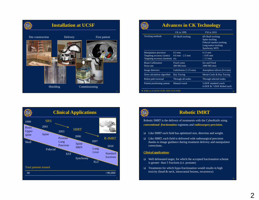
Installation at UCSF
Site construction First patient
Shielding
Delivery
Commissioning
6
Advances in CK Technology
W. Kilby et al (2010) TCRT, ISSN 1533-0346
3D Skull tracking 6D Skull trackingSpine trackingFiducial marker trackingLung tumor tracking Synchrony MTS
Manipulator precision 0.5 mm 0.12 mmTargeting accuracy (static) 0.6 mm – 2.5 mm ≤ 0.95 mmTargeting accuracy (motion) n/a ≤ 1.5 mm
Beam Collimation Fixed cones Iris and FixedDose-rate 300 MU/min 1000 MU/min
Image detectors Gadolinium (1.25 mm) Amorphous silicon (0.4 mm)
Dose calculation algorithm Ray Tracing Monte-Carlo & Ray Tracing
Robot path traversal Through all nodes Through selected nodes
Patient positioning system Manual couch 5-DOF standard couch6-DOF & 7-DOF RoboCouch
CK in 1999 VSI in 2010
Tracking methods
7
Clinical Applications
Standard fractions
1999
2010
BrainUpper spine Spine
2001
Prostate LungPancreas
2003
Skull
Fiducial
SpineH&N
XST
2006
Synchrony
2007
LungLiver
30 >90,000
XLT
SRS
SBRT
R-IMRT
Total patients treated
8
Robotic IMRT
Robotic IMRT is the delivery of treatments with the CyberKnife using
conventional fractionationregimens and radiosurgery precision.
� Well delineated target, for which the accepted fractionation scheme is greater than 5 fractions (i.e. prostate)
� Treatments for which hypo-fractionation would results in high toxicity (head & neck, intracranial lesions, recurrence)
Clinical applications:
� Like IMRT each field has optimized size, direction and weight.
� Like SBRT, each field is delivered with radiosurgical precision thanks to image guidance during treatment delivery and manipulator corrections.
3
9
Clinical Example
� Infindibular hemangioblastoma
� 54 Gy in 30 fractions to 85%
� Critical structures: optic chiasm, pituitary, hypothalamus, brain stem
� 80 Beams, 5 mm fixed collimator
� Treatment time: 18 minutes
10
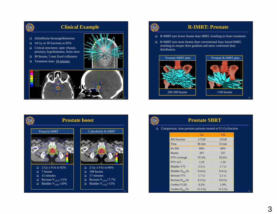
R-IMRT: Prostate
� R-IMRT uses fewer beams than SBRT, resulting in faster treatment.
� R-IMRT uses more beams than conventional linac-based IMRT, resulting in steeper dose gradient and more conformal dose distribution.
Prostate SBRT plan
200-300 beams
Prostate R-IMRT plan
<100 beams
11
Prostate boost
� 2 Gy x 9 fx to 92%� 7 beams� 15 minutes� Rectum V12Gy=11%� Bladder V12Gy=20%
� 2 Gy x 9 fx to 86%� 108 beams� 17 minutes � Rectum V12Gy=7.7%� Bladder V12Gy=15%
CyberKnife R-IMRTPinnacle IMRT
12
Prostate SBRT
� Comparison: nine prostate patients treated at 9.5 Gy/fraction
G3 VSI
MU/fraction 17158 15538
Time 86 min 53 min
Rx IDL 68% 68%
Beams 207 257
PTV coverage 97.4% 95.6%
PTV nCI 1.19 1.16
Bladder V75 2.3 cc 1.7 cc
Bladder Dmax/fx 9.4 Gy 9.4 Gy
Rectum V75 1.7 cc 2.1 cc
Rectum Dmax/fx 9.3 Gy 9.6 Gy
Urethra V120 0.2% 1.9%
Urethra Dmax/fx 11.3 Gy 11.5 Gy

4
13
Tools for R-IMRT
� Sequential Optimization
� Iris Variable Aperture Collimator
� Patient specific QA
The capability of CyberKnife to deliver R-IMRT treatments was
enhanced by the following developments:
These developments also resulted in improved SRS/SBRT
treatments.
CyberKnife remains primarily a radiosurgery system
14
Sequential Optimization
� In conventional optimization algorithms, multiple objectives are grouped in a single cost function.
� In sequential optimization, each objective (step) is optimized in sequence.
� The objective and the order of the steps define the clinical priorities.
� Auto-shellsare tuning structures used to constrain the confomality and the extension of the low-dose region.
� Beam reductionremoves all beams below a MU threshold and re-optimize the plans with the remaining beams while preserving the plan quality.
� Time reductionreduces the number of beams and nodes to achieve the user-defined time goal.
15
Time Reduction
� Rx IDL = 66%� 360 beams� 60 minutes� Rectum V75%= 1.2 cc� Bladder V75%= 1.8 cc
� Rx IDL = 61%� 199 beams� 40 minutes � Rectum V75%= 1.3 cc� Bladder V75%= 2.1 cc
Plan after time reductionInitial Plan
16
Iris variable aperture collimator
� The aperture is produced by 2 hexagonal banks of tungsten which produce a 12-sided radiation beam.
� The same twelve field sizes can be obtained: 5, 7.5, 10, 12.5, 15, 20, 25, 30, 35, 40, 50, 60 mm
� The beam characteristics are practically identical to the fixed cones.
� Plans generated using multiple field size have better quality(conformality, homogeneity, coverage) and lower MU than plans generated using a single field size.
� However, using multiple fixed cones is not practical because it requires multiple paths traversal, and results in prohibitively long treatment time.
� Iris collimator allows to use of multiple field sizes without these limitations.
5
17
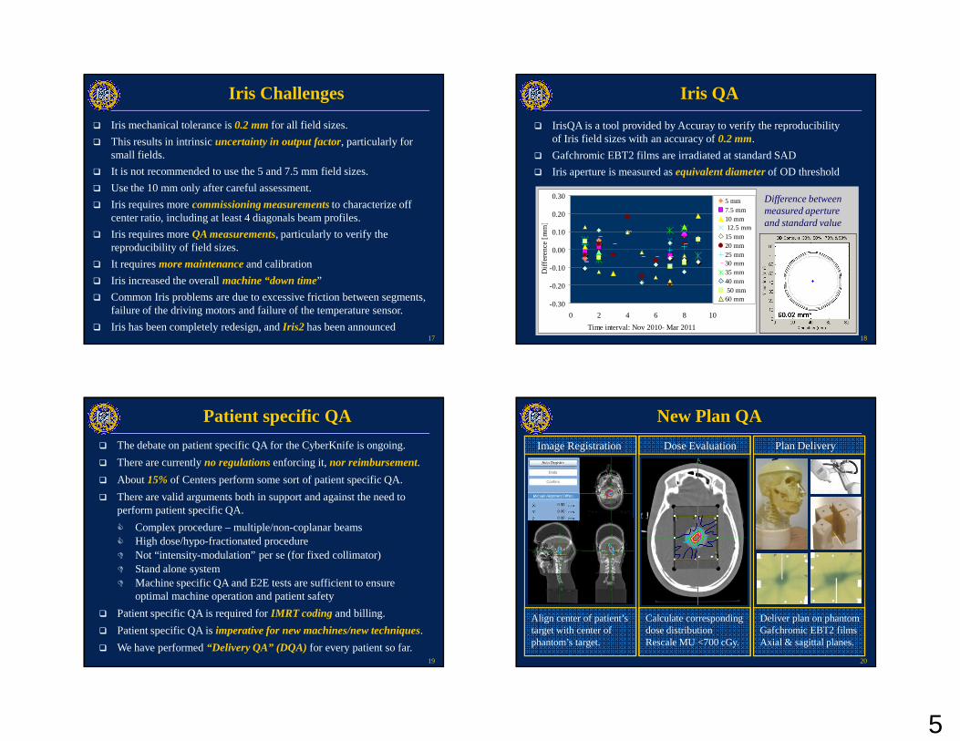
Iris Challenges
� Iris mechanical tolerance is 0.2 mmfor all field sizes.
� This results in intrinsic uncertainty in output factor, particularly for small fields.
� It is not recommended to use the 5 and 7.5 mm field sizes.
� Use the 10 mm only after careful assessment.
� Iris requires more commissioning measurementsto characterize off center ratio, including at least 4 diagonals beam profiles.
� Iris requires more QA measurements, particularly to verify the reproducibility of field sizes.
� It requires more maintenanceand calibration
� Iris increased the overall machine “down time”
� Common Iris problems are due to excessive friction between segments, failure of the driving motors and failure of the temperature sensor.
� Iris has been completely redesign, and Iris2 has been announced18
Iris QA
� IrisQA is a tool provided by Accuray to verify the reproducibility of Iris field sizes with an accuracy of 0.2 mm.
� Gafchromic EBT2 films are irradiated at standard SAD
� Iris aperture is measured as equivalent diameterof OD threshold
Difference between measured aperture and standard value
-0.30
-0.20
-0.10
0.00
0.10
0.20
0.30
0 2 4 6 8 10
Time interval: Nov 2010- Mar 2011
Diff
eren
ce [
mm
]
5 mm7.5 mm10 mm 12.5 mm15 mm20 mm25 mm30 mm35 mm40 mm 50 mm60 mm
19
Patient specific QA
� The debate on patient specific QA for the CyberKnife is ongoing.
� There are currently no regulationsenforcing it, nor reimbursement.
� About 15% of Centers perform some sort of patient specific QA.
� There are valid arguments both in support and against the need to perform patient specific QA.
� Complex procedure – multiple/non-coplanar beams� High dose/hypo-fractionated procedure� Not “intensity-modulation” per se (for fixed collimator)� Stand alone system � Machine specific QA and E2E tests are sufficient to ensure
optimal machine operation and patient safety
� Patient specific QA is required for IMRT coding and billing.
� Patient specific QA is imperative for new machines/new techniques.
� We have performed “Delivery QA” (DQA) for every patient so far.20
New Plan QA
Calculate corresponding dose distributionRescale MU <700 cGy.
Image Registration Dose Evaluation Plan Delivery
Align center of patient’s target with center of phantom’s target.
Deliver plan on phantomGafchromic EBT2 films Axial & sagittal planes.

6
21
Film Analysis
Film Planned dose Dose comparison
Dose profile comparison Statistical analysis
- Planned dose- Film
22
80
85
90
95
100
105
Patient number
Po
ints
pas
sing
(%
)
Axial FilmSagittal Film
DQA Results
80
85
90
95
100
105
Patient number
Po
ints
pa
ssin
g (
%)
Coronal Film
� MapCheck film analysis software
� Gamma Index 3%/3mm
� Absolute dose� 48 plans� Average score 97%
� FilmQA analysis software
� Gamma Index 2%/1mm
� Absolute dose� 8 plans� Average score 98%
23
Summary
� The capabilities of the CyberKnife system have significantly expanded over the last decade.
� New developments in CyberKnife technology enable delivery of Robotic-IMRT treatments.
� All development done towards robotic-IMRT results in improved SRS/SBRT treatments.
� While CyberKnife is becoming more versatile, it remains primarily a radiosurgery system.
24
Acknowledgment
Alex GottschalkSue YomIgor BaraniPenny SneedDavid LarsonJean NakamuraMarc NashI-Chow HsuShannon FoghCatherine ParkMack Roach
UCSF CyberKnife Team
Mike LomettiSebastien GrosCynthia ChuangLijun MaJean Pouliot
UCSF Comprehensive Cancer CenterUCSF Comprehensive Cancer CenterSan FranciscoSan FranciscoUCSF Comprehensive Cancer CenterUCSF Comprehensive Cancer CenterSan FranciscoSan Francisco
Vernon CheamMaria Ho
Michael McDermott