VS1053B / VS1063A WAV PCM RECORDER VSMPG “VLSI … · VS1053B / VS1063A WAV PCM RECORDER VSMPG 2...
27
P UBLIC DOCUMENT VS1053 B / VS1063 A WAV PCM R ECORDER VSMPG “VLSI Solution Audio Decoder” Project Code: Project Name: VSMPG All information in this document is provided as-is without warranty. Features are subject to change without notice. Revision History Rev. Date Author Description 1.31 2017-02-08 HH Profiles are now offered also in .img file format. 1.30 2015-03-12 HH Added VS1063a support. VS1063a added to package name. 1.20 2015-03-12 HH New profiles other than 48 kHz stereo supported (Chapter 2.2). 1.10 2015-01-09 HH DREQ fixed. Added Chapter 4, Troubleshooting. 1.00 2013-07-12 HH Documentation update. Software unchanged. 0.90 2010-06-28 HH Initial release. Rev. 1.31 2017-02-08 Page 1(27)
Transcript of VS1053B / VS1063A WAV PCM RECORDER VSMPG “VLSI … · VS1053B / VS1063A WAV PCM RECORDER VSMPG 2...
PUBLIC DOCUMENT
VS1053B / VS1063A WAV PCM RECORDER
VSMPG “VLSI Solution Audio Decoder”
Project Code:Project Name: VSMPG
All information in this document is provided as-is without warranty. Features aresubject to change without notice.
Revision HistoryRev. Date Author Description
1.31 2017-02-08 HH Profiles are now offered also in .img file format.1.30 2015-03-12 HH Added VS1063a support. VS1063a added to
package name.1.20 2015-03-12 HH New profiles other than 48 kHz stereo supported
(Chapter 2.2).1.10 2015-01-09 HH DREQ fixed. Added Chapter 4, Troubleshooting.1.00 2013-07-12 HH Documentation update. Software unchanged.0.90 2010-06-28 HH Initial release.
Rev. 1.31 2017-02-08 Page 1(27)
HH
VS1053B / VS1063A WAV PCM RECORDER VSMPG
Contents
VS1053b / VS1063a WAV PCM Recorder Front Page 1
Table of Contents 2
1 Introduction 4
2 The VS1053b / VS1063a WAV PCM Recorder 52.1 Limitations and Requirements . . . . . . . . . . . . . . . . . . . . . . . . . 52.2 Audio Profiles . . . . . . . . . . . . . . . . . . . . . . . . . . . . . . . . . . 62.3 Running the VS1053b / VS1063a WAV PCM Recorder . . . . . . . . . . . 7
2.3.1 VS1053b / VS1063a WAV PCM Recorder Registers . . . . . . . . 72.3.2 Loading and Starting the Code . . . . . . . . . . . . . . . . . . . . 82.3.3 Reading PCM Data . . . . . . . . . . . . . . . . . . . . . . . . . . 92.3.4 Reading Additional Data while Recording PCM . . . . . . . . . . . 102.3.5 Finishing PCM Recording . . . . . . . . . . . . . . . . . . . . . . . 102.3.6 Filling File Size Data to a PCM RIFF Header . . . . . . . . . . . . 11
2.4 Recording Levels and Automatic Gain Control (AGC) . . . . . . . . . . . . 122.4.1 Reading the Recording Level . . . . . . . . . . . . . . . . . . . . . 122.4.2 Setting AGC . . . . . . . . . . . . . . . . . . . . . . . . . . . . . . 132.4.3 Building a Useful VU Meter . . . . . . . . . . . . . . . . . . . . . . 142.4.4 Converting from Linear to Decibel Scale . . . . . . . . . . . . . . . 16
3 Recorder Performance 173.1 Playback Performance . . . . . . . . . . . . . . . . . . . . . . . . . . . . . 17
3.1.1 Playback Interchannel Isolation . . . . . . . . . . . . . . . . . . . . 173.1.2 Playback Noise and THD Ratios . . . . . . . . . . . . . . . . . . . 183.1.3 Playback Frequency Response . . . . . . . . . . . . . . . . . . . . 19
3.2 Recording Performance . . . . . . . . . . . . . . . . . . . . . . . . . . . . 203.2.1 Recording Noise and THD Ratios . . . . . . . . . . . . . . . . . . . 213.2.2 Recording Frequency Response . . . . . . . . . . . . . . . . . . . 223.2.3 Recording Monitor Frequency Response . . . . . . . . . . . . . . 23
4 Troubleshooting 244.1 The Encoder Doesn’t Start . . . . . . . . . . . . . . . . . . . . . . . . . . 244.2 Data Starts with Two Zeroes . . . . . . . . . . . . . . . . . . . . . . . . . . 244.3 Data Bytes Are Inverted . . . . . . . . . . . . . . . . . . . . . . . . . . . . 24
5 How to Load a Plugin 255.1 How to Load a .PLG File . . . . . . . . . . . . . . . . . . . . . . . . . . . . 255.2 How to Load an .IMG File . . . . . . . . . . . . . . . . . . . . . . . . . . . 26
6 Contact Information 27
Rev. 1.31 2017-02-08 Page 2(27)
HH
VS1053B / VS1063A WAV PCM RECORDER VSMPG
List of Figures
1 Example colour VU meter. . . . . . . . . . . . . . . . . . . . . . . . . . . . 142 Example monochrome VU meter. . . . . . . . . . . . . . . . . . . . . . . . 143 Real record display with monochrome VU meter. . . . . . . . . . . . . . . 154 Playback noise + THD ratios. . . . . . . . . . . . . . . . . . . . . . . . . . 185 Playback frequency response. . . . . . . . . . . . . . . . . . . . . . . . . 196 Recording noise + THD ratios. . . . . . . . . . . . . . . . . . . . . . . . . 217 Recording frequency response. . . . . . . . . . . . . . . . . . . . . . . . . 228 Recording image rejection frequency response. . . . . . . . . . . . . . . . 229 Recording monitor frequency response. . . . . . . . . . . . . . . . . . . . 23
Rev. 1.31 2017-02-08 Page 3(27)
HH
VS1053B / VS1063A WAV PCM RECORDER VSMPG
1 Introduction
This document is an instruction manual on how to use the VS1053b / VS1063a WAVPCM Recorder application. The document is arranged as follows.
Chapter 2 describes the application, then tells how to load and run it. It also discussesrecording levels and recording level meters.
Chapter 3 contains performance measurements.
Chapter 4 presents some typical problems and solutions to them.
Chapter 5 tells how to load a plugin code to a VS10XX chip.
Finally, Chapter 6 contains VLSI Solution’s contact information.
Rev. 1.31 2017-02-08 Page 4(27)
HH
VS1053B / VS1063A WAV PCM RECORDER VSMPG
2 The VS1053b / VS1063a WAV PCM Recorder
The VS1053b / VS1063a WAV PCM Recorder Application is a 48 kHz / 24 kHz WAV/PCMstereo / mono encoder for VLSI Solution’s VS1053b / VS1063a integrated circuit.
The Recorder has been optimized for best possible audio quality.
The Recorder also offers a data buffer which is significantly larger than the buffer of-fered by VS1053b / VS1063a’s firmware. Even using the highest quality 48 kHz stereoPCM profile the buffer lasts for 404 ms as opposed to VS1053b’s default 10.5 ms, orVS1063a’s default 36 ms. This helps particularly if saving audio data to an SD card,because SD cards can lock up for significant times when doing internal block eraseoperations.
Unlike VS1053b’s firmware encoder, the Recorder output contains a standard RIFF WAVheader.
Some key features of the recorder are:• Recordings are made at 48 kHz or 24 kHz in 16-bit stereo or mono PCM format.• Dynamic range with best profile 95 dB, S/N ratio 86 dB, THD 0.013 %, frequency
response 20-20000 Hz. (Chapter 3.2)• 76.5 KiB internal audio buffer (404 ms at 48 kHz stereo).
The VS1053b / VS1063a WAV PCM Recorder is provided as a plugin, downloadable athttp://www.vlsi.fi/en/support/software/vs10xxapplications.html .
2.1 Limitations and Requirements
• Maximum SPI (SCI) clock speed is internal clock / 7. For a typical crystal of 12.288MHz and internal 4.5x clock of 55.296 MHz, the maximum speed is then 7.8 Mbit/s.If a higher SPI speed is used, there may be data read errors.
• For the sample rate to be exactly correct, the crystal needs to be 12.288 MHz.With other clocks, the sample rate is fs = 48×c
12.288 where c is the crystal frequency inMHz.
• Even when recording mono sound, earphone monitoring is in stereo.
• Even when recording mono sound, Automatic Gain Control (AGC) works in stereomode.
Rev. 1.31 2017-02-08 Page 5(27)
HH
VS1053B / VS1063A WAV PCM RECORDER VSMPG
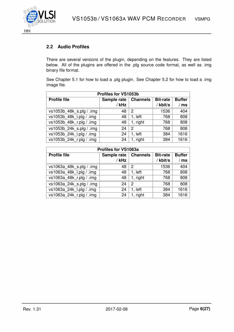
2.2 Audio Profiles
There are several versions of the plugin, depending on the features. They are listedbelow. All of the plugins are offered in the .plg source code format, as well as .imgbinary file format.
See Chapter 5.1 for how to load a .plg plugin. See Chapter 5.2 for how to load a .imgimage file.
Profiles for VS1053bProfile file Sample rate Channels Bit-rate Buffer
/ kHz / kbit/s / msvs1053b_48k_s.plg / .img 48 2 1536 404vs1053b_48k_l.plg / .img 48 1, left 768 808vs1053b_48k_r.plg / .img 48 1, right 768 808vs1053b_24k_s.plg / .img 24 2 768 808vs1053b_24k_l.plg / .img 24 1, left 384 1616vs1053b_24k_r.plg / .img 24 1, right 384 1616
Profiles for VS1063aProfile file Sample rate Channels Bit-rate Buffer
/ kHz / kbit/s / msvs1063a_48k_s.plg / .img 48 2 1536 404vs1063a_48k_l.plg / .img 48 1, left 768 808vs1063a_48k_r.plg / .img 48 1, right 768 808vs1063a_24k_s.plg / .img 24 2 768 808vs1063a_24k_l.plg / .img 24 1, left 384 1616vs1063a_24k_r.plg / .img 24 1, right 384 1616
Rev. 1.31 2017-02-08 Page 6(27)
HH
VS1053B / VS1063A WAV PCM RECORDER VSMPG
2.3 Running the VS1053b / VS1063a WAV PCM Recorder
2.3.1 VS1053b / VS1063a WAV PCM Recorder Registers
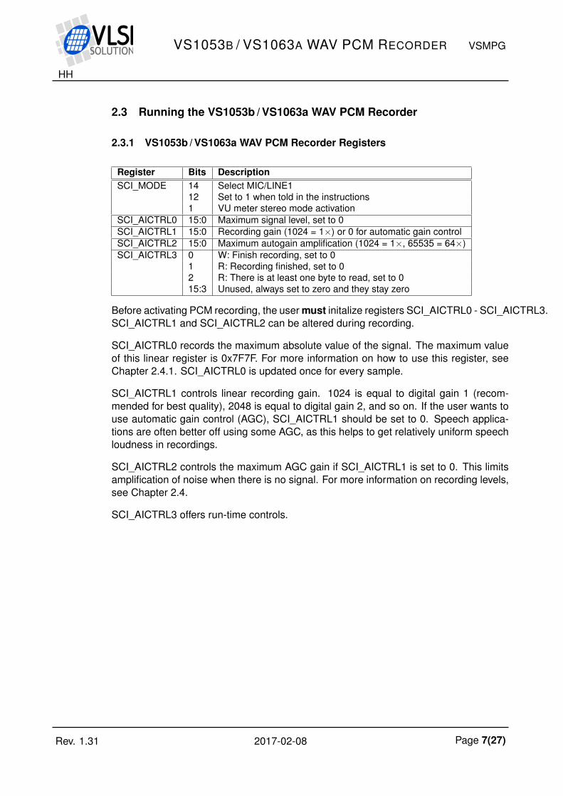
Register Bits DescriptionSCI_MODE 14 Select MIC/LINE1
12 Set to 1 when told in the instructions1 VU meter stereo mode activation
SCI_AICTRL0 15:0 Maximum signal level, set to 0SCI_AICTRL1 15:0 Recording gain (1024 = 1×) or 0 for automatic gain controlSCI_AICTRL2 15:0 Maximum autogain amplification (1024 = 1×, 65535 = 64×)SCI_AICTRL3 0 W: Finish recording, set to 0
1 R: Recording finished, set to 02 R: There is at least one byte to read, set to 015:3 Unused, always set to zero and they stay zero
Before activating PCM recording, the user must initalize registers SCI_AICTRL0 - SCI_AICTRL3.SCI_AICTRL1 and SCI_AICTRL2 can be altered during recording.
SCI_AICTRL0 records the maximum absolute value of the signal. The maximum valueof this linear register is 0x7F7F. For more information on how to use this register, seeChapter 2.4.1. SCI_AICTRL0 is updated once for every sample.
SCI_AICTRL1 controls linear recording gain. 1024 is equal to digital gain 1 (recom-mended for best quality), 2048 is equal to digital gain 2, and so on. If the user wants touse automatic gain control (AGC), SCI_AICTRL1 should be set to 0. Speech applica-tions are often better off using some AGC, as this helps to get relatively uniform speechloudness in recordings.
SCI_AICTRL2 controls the maximum AGC gain if SCI_AICTRL1 is set to 0. This limitsamplification of noise when there is no signal. For more information on recording levels,see Chapter 2.4.
SCI_AICTRL3 offers run-time controls.
Rev. 1.31 2017-02-08 Page 7(27)
HH
VS1053B / VS1063A WAV PCM RECORDER VSMPG
2.3.2 Loading and Starting the Code
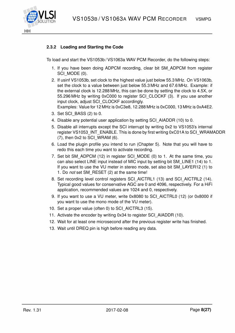
To load and start the VS1053b / VS1063a WAV PCM Recorder, do the following steps:
1. If you have been doing ADPCM recording, clear bit SM_ADPCM from registerSCI_MODE (0).
2. If usinf VS1053b, set clock to the highest value just below 55.3 MHz. On VS1063b,set the clock to a value between just below 55.3 MHz and 67.6 MHz. Example: ifthe external clock is 12.288 MHz, this can be done by setting the clock to 4.5X, or55.296 MHz by writing 0xC000 to register SCI_CLOCKF (3). If you use anotherinput clock, adjust SCI_CLOCKF accordingly.Examples: Value for 12 MHz is 0xC3e8, 12.288 MHz is 0xC000, 13 MHz is 0xA4E2.
3. Set SCI_BASS (2) to 0.4. Disable any potential user application by setting SCI_AIADDR (10) to 0.5. Disable all interrupts except the SCI interrupt by writing 0x2 to VS1053’s internal
register VS1053_INT_ENABLE. This is done by first writing 0xC01A to SCI_WRAMADDR(7), then 0x2 to SCI_WRAM (6).
6. Load the plugin profile you intend to run (Chapter 5). Note that you will have toredo this each time you want to activate recording.
7. Set bit SM_ADPCM (12) in register SCI_MODE (0) to 1. At the same time, youcan also select LINE input instead of MIC input by setting bit SM_LINE1 (14) to 1.If you want to use the VU meter in stereo mode, set also bit SM_LAYER12 (1) to1. Do not set SM_RESET (2) at the same time!
8. Set recording level control registers SCI_AICTRL1 (13) and SCI_AICTRL2 (14).Typical good values for conservative AGC are 0 and 4096, respectively. For a HiFiapplication, recommended values are 1024 and 0, respectively.
9. If you want to use a VU meter, write 0x8080 to SCI_AICTRL0 (12) (or 0x8000 ifyou want to use the mono mode of the VU meter).
10. Set a proper value (often 0) to SCI_AICTRL3 (15).11. Activate the encoder by writing 0x34 to register SCI_AIADDR (10).12. Wait for at least one microsecond after the previous register write has finished.13. Wait until DREQ pin is high before reading any data.
Rev. 1.31 2017-02-08 Page 8(27)
HH
VS1053B / VS1063A WAV PCM RECORDER VSMPG
2.3.3 Reading PCM Data
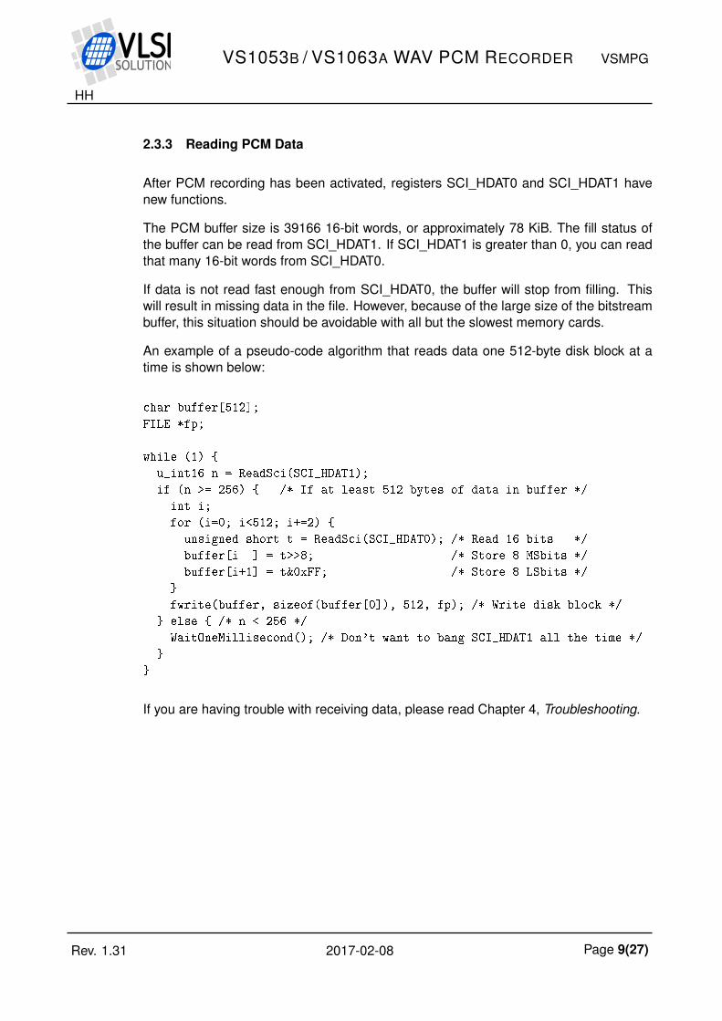
After PCM recording has been activated, registers SCI_HDAT0 and SCI_HDAT1 havenew functions.
The PCM buffer size is 39166 16-bit words, or approximately 78 KiB. The fill status ofthe buffer can be read from SCI_HDAT1. If SCI_HDAT1 is greater than 0, you can readthat many 16-bit words from SCI_HDAT0.
If data is not read fast enough from SCI_HDAT0, the buffer will stop from filling. Thiswill result in missing data in the file. However, because of the large size of the bitstreambuffer, this situation should be avoidable with all but the slowest memory cards.
An example of a pseudo-code algorithm that reads data one 512-byte disk block at atime is shown below:
char buffer[512];
FILE *fp;
while (1)
u_int16 n = ReadSci(SCI_HDAT1);
if (n >= 256) /* If at least 512 bytes of data in buffer */
int i;
for (i=0; i<512; i+=2)
unsigned short t = ReadSci(SCI_HDAT0); /* Read 16 bits */
buffer[i ] = t>>8; /* Store 8 MSbits */
buffer[i+1] = t&0xFF; /* Store 8 LSbits */
fwrite(buffer, sizeof(buffer[0]), 512, fp); /* Write disk block */
else /* n < 256 */
WaitOneMillisecond(); /* Don't want to bang SCI_HDAT1 all the time */
If you are having trouble with receiving data, please read Chapter 4, Troubleshooting.
Rev. 1.31 2017-02-08 Page 9(27)
HH
VS1053B / VS1063A WAV PCM RECORDER VSMPG
2.3.4 Reading Additional Data while Recording PCM
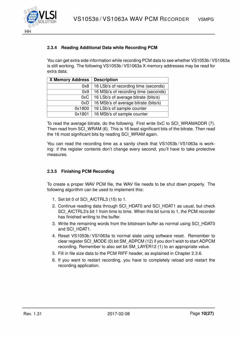
You can get extra side information while recording PCM data to see whether VS1053b / VS1063ais still working. The following VS1053b / VS1063a X memory addresses may be read forextra data:
X Memory Address Description0x8 16 LSb’s of recording time (seconds)0x9 16 MSb’s of recording time (seconds)0xC 16 LSb’s of average bitrate (bits/s)0xD 16 MSb’s of average bitrate (bits/s)
0x1800 16 LSb’s of sample counter0x1801 16 MSb’s of sample counter
To read the average bitrate, do the following. First write 0xC to SCI_WRAMADDR (7).Then read from SCI_WRAM (6). This is 16 least significant bits of the bitrate. Then readthe 16 most significant bits by reading SCI_WRAM again.
You can read the recording time as a sanity check that VS1053b / VS1063a is work-ing: if the register contents don’t change every second, you’ll have to take protectivemeasures.
2.3.5 Finishing PCM Recording
To create a proper WAV PCM file, the WAV file needs to be shut down properly. Thefollowing algorithm can be used to implement this:
1. Set bit 0 of SCI_AICTRL3 (15) to 1.2. Continue reading data through SCI_HDAT0 and SCI_HDAT1 as usual, but check
SCI_AICTRL3’s bit 1 from time to time. When this bit turns to 1, the PCM recorderhas finished writing to the buffer.
3. Write the remaining words from the bitstream buffer as normal using SCI_HDAT0and SCI_HDAT1.
4. Reset VS1053b / VS1063a to normal state using software reset. Remember toclear register SCI_MODE (0) bit SM_ADPCM (12) if you don’t wish to start ADPCMrecording. Remember to also set bit SM_LAYER12 (1) to an appropriate value.
5. Fill in file size data to the PCM RIFF header, as explained in Chapter 2.3.6.6. If you want to restart recording, you have to completely reload and restart the
recording application.
Rev. 1.31 2017-02-08 Page 10(27)
HH
VS1053B / VS1063A WAV PCM RECORDER VSMPG
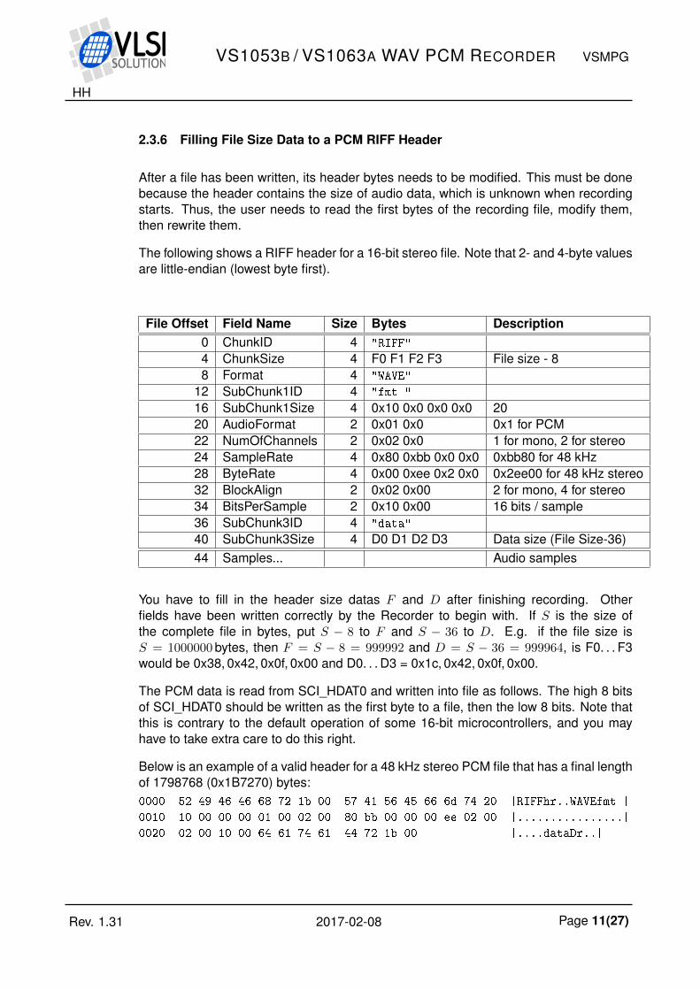
2.3.6 Filling File Size Data to a PCM RIFF Header
After a file has been written, its header bytes needs to be modified. This must be donebecause the header contains the size of audio data, which is unknown when recordingstarts. Thus, the user needs to read the first bytes of the recording file, modify them,then rewrite them.
The following shows a RIFF header for a 16-bit stereo file. Note that 2- and 4-byte valuesare little-endian (lowest byte first).
File Offset Field Name Size Bytes Description0 ChunkID 4 "RIFF"
4 ChunkSize 4 F0 F1 F2 F3 File size - 88 Format 4 "WAVE"
12 SubChunk1ID 4 "fmt "
16 SubChunk1Size 4 0x10 0x0 0x0 0x0 2020 AudioFormat 2 0x01 0x0 0x1 for PCM22 NumOfChannels 2 0x02 0x0 1 for mono, 2 for stereo24 SampleRate 4 0x80 0xbb 0x0 0x0 0xbb80 for 48 kHz28 ByteRate 4 0x00 0xee 0x2 0x0 0x2ee00 for 48 kHz stereo32 BlockAlign 2 0x02 0x00 2 for mono, 4 for stereo34 BitsPerSample 2 0x10 0x00 16 bits / sample36 SubChunk3ID 4 "data"
40 SubChunk3Size 4 D0 D1 D2 D3 Data size (File Size-36)44 Samples... Audio samples
You have to fill in the header size datas F and D after finishing recording. Otherfields have been written correctly by the Recorder to begin with. If S is the size ofthe complete file in bytes, put S − 8 to F and S − 36 to D. E.g. if the file size isS = 1000000 bytes, then F = S − 8 = 999992 and D = S − 36 = 999964, is F0. . . F3would be 0x38, 0x42, 0x0f, 0x00 and D0. . . D3 = 0x1c, 0x42, 0x0f, 0x00.
The PCM data is read from SCI_HDAT0 and written into file as follows. The high 8 bitsof SCI_HDAT0 should be written as the first byte to a file, then the low 8 bits. Note thatthis is contrary to the default operation of some 16-bit microcontrollers, and you mayhave to take extra care to do this right.
Below is an example of a valid header for a 48 kHz stereo PCM file that has a final lengthof 1798768 (0x1B7270) bytes:0000 52 49 46 46 68 72 1b 00 57 41 56 45 66 6d 74 20 |RIFFhr..WAVEfmt |
0010 10 00 00 00 01 00 02 00 80 bb 00 00 00 ee 02 00 |................|
0020 02 00 10 00 64 61 74 61 44 72 1b 00 |....dataDr..|
Rev. 1.31 2017-02-08 Page 11(27)

HH
VS1053B / VS1063A WAV PCM RECORDER VSMPG
2.4 Recording Levels and Automatic Gain Control (AGC)
The Recorder offers signal level monitoring through SCI_AICTRL0. It is recommendedthat devices that offer recording would show a signal level in a decibel scale. For thedecibel scale, see Chapter 2.4.4. This can be done by showing and clearing SCI_AICTRL0contents at regular intervals.
A good VU meter should be implemented in such a way that it visually advices the userto avoid using the last 6 dB of the available dynamic range.
2.4.1 Reading the Recording Level
The recording level meter has two settings: mono and stereo. Mono mode records thecombined highest sample value while stereo mode records the highest absolute valuefor each channel separately. It is compatible with the Ogg Vorbis Encoder VU meter.
Recording Level Meter: Stereo Mode
Activate stereo mode by setting SCI_MODE (0) register bit SM_LAYER12 (1) to 1.
To read the left and right channel levels, repeat the following loop:
• Write 0x8080 to SCI_AICTRL0.• Wait for at least 1/50 s. Note: Constant reading of side information causes load on
the VS10XX and may cause unexpected crackles in sound.• Check whether SCI_AICTRL0 & 0x8080 is 0. If not, wait a little more and read
again.• Left channel value is SCI_AICTRL0 & 0x7F00.• Right channel value is (SCI_AICTRL0 & 0x7F) × 256.• Use the values as explained in this Chapter. Repeat the loop.
Recording Level Meter: Mono Mode
Activate mono mode by clearing SCI_MODE (0) register bit SM_LAYER12 (1) to 0.
To read the level, repeat the following loop:
• Write 0x8000 to SCI_AICTRL0.• Wait for at least 1/50 s. Note: Constant reading of side information causes load on
the VS10XX and may cause unexpected crackles in sound.• Check whether SCI_AICTRL0 & 0x8000 is 0x0. If not, wait a little more and read
again.• Use the value as explained in this Chapter. Repeat the loop.
Rev. 1.31 2017-02-08 Page 12(27)
HH
VS1053B / VS1063A WAV PCM RECORDER VSMPG
2.4.2 Setting AGC
When the highest dynamic range and sound fidelity is required, AGC should be turnedoff and recording gain should be set to 1 (SCI_AICTRL1 = 1024). A good example of thiswould be music recording, although there might be cases where recording level controlwould be needed even with these cases.
However, in some cases it is required that the audio dynamic range is compressed.An example of such a case is when a device should retain a uniform recording levelof a discussion of several people or of one person moving closer and further from therecording device. In such a case, it is a good idea to use AGC.
The AGC unit adjusts signal power in such a way that the maximum sample value froma sine wave would become as close to 16300 as possible. If the signal is too strong,recording level is decreased, and vice versa. The maximum recording level can be setwith register SCI_AICTRL2.
When AGC is used, conservetive maximum gain values often give the best soundingresults. Example: 12 dB (SCI_AICTRL1 = 0, SCI_AICTRL2 = 4096). In some casesmore extreme values may help to make quiet speech more intelligible, but such valuesmay also add excessive background noise and make sound quality less pleasing.
Rev. 1.31 2017-02-08 Page 13(27)
HH
VS1053B / VS1063A WAV PCM RECORDER VSMPG
2.4.3 Building a Useful VU Meter
In an encoder application, if the recording level is too low, extraneous background noisemay be introduced to the sound. Conversely, if the recording level is so high that thehighest values cannot be represented numerically, signal clipping occurs, and this maycause severe distortion to sound.
In a recording device, it is useful to have a VU meter that shows the signal level so thatboth too low signal levels and clipping is avoided. This is very important so that the userhas a chance to either adjust the recording or input signal level.
0−6−12−20−30−40
−40 dB = 161
−30 dB = 512
−20 dB = 1625
−12 dB = 4096
−6 dB = 8192
0 dB = 16384
+5 dB = 29193
OVERLOAD = 29193
+5
OVERLOAD
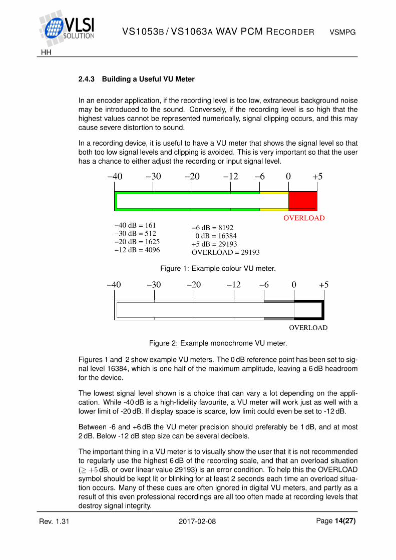
Figure 1: Example colour VU meter.
0−6−12−20−30−40 +5
OVERLOAD
Figure 2: Example monochrome VU meter.
Figures 1 and 2 show example VU meters. The 0 dB reference point has been set to sig-nal level 16384, which is one half of the maximum amplitude, leaving a 6 dB headroomfor the device.
The lowest signal level shown is a choice that can vary a lot depending on the appli-cation. While -40 dB is a high-fidelity favourite, a VU meter will work just as well with alower limit of -20 dB. If display space is scarce, low limit could even be set to -12 dB.
Between -6 and +6 dB the VU meter precision should preferably be 1 dB, and at most2 dB. Below -12 dB step size can be several decibels.
The important thing in a VU meter is to visually show the user that it is not recommendedto regularly use the highest 6 dB of the recording scale, and that an overload situation(≥ +5 dB, or over linear value 29193) is an error condition. To help this the OVERLOADsymbol should be kept lit or blinking for at least 2 seconds each time an overload situa-tion occurs. Many of these cues are often ignored in digital VU meters, and partly as aresult of this even professional recordings are all too often made at recording levels thatdestroy signal integrity.
Rev. 1.31 2017-02-08 Page 14(27)
HH
VS1053B / VS1063A WAV PCM RECORDER VSMPG
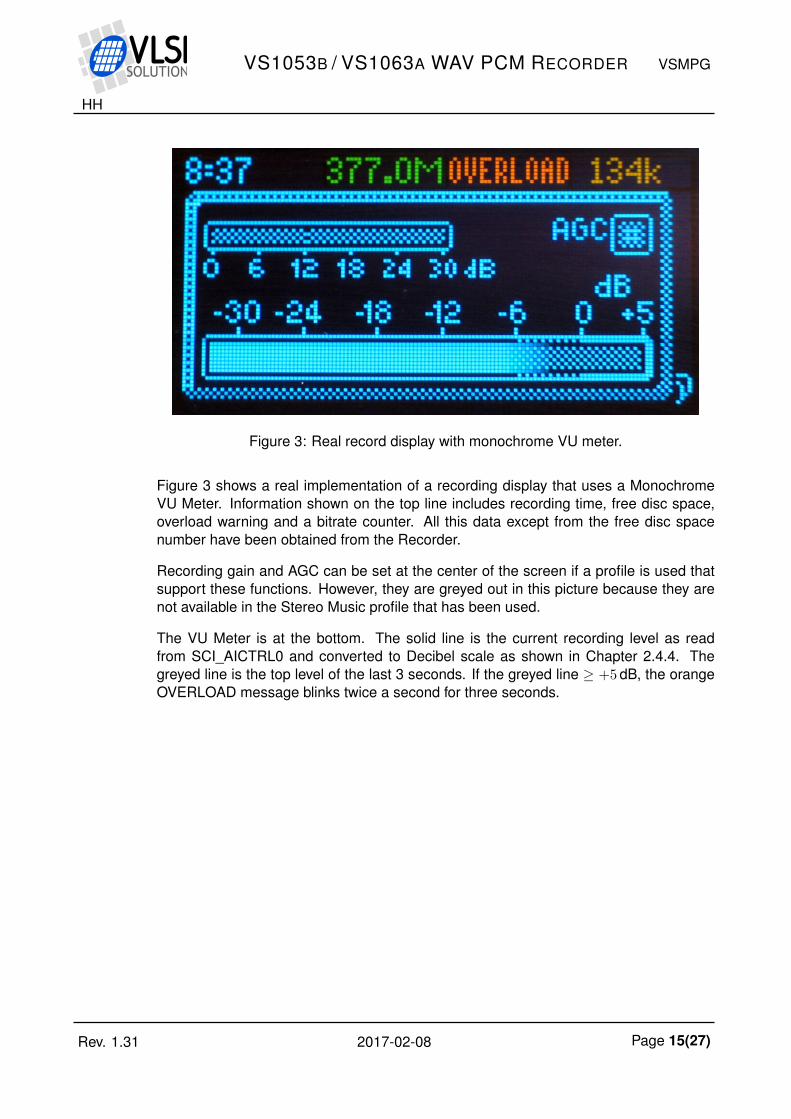
Figure 3: Real record display with monochrome VU meter.
Figure 3 shows a real implementation of a recording display that uses a MonochromeVU Meter. Information shown on the top line includes recording time, free disc space,overload warning and a bitrate counter. All this data except from the free disc spacenumber have been obtained from the Recorder.
Recording gain and AGC can be set at the center of the screen if a profile is used thatsupport these functions. However, they are greyed out in this picture because they arenot available in the Stereo Music profile that has been used.
The VU Meter is at the bottom. The solid line is the current recording level as readfrom SCI_AICTRL0 and converted to Decibel scale as shown in Chapter 2.4.4. Thegreyed line is the top level of the last 3 seconds. If the greyed line ≥ +5 dB, the orangeOVERLOAD message blinks twice a second for three seconds.
Rev. 1.31 2017-02-08 Page 15(27)
HH
VS1053B / VS1063A WAV PCM RECORDER VSMPG
2.4.4 Converting from Linear to Decibel Scale
To convert from linear to dB scale, use the formuladB = 20 × log10(
m32768) + 96
where dB is the result and m is a value returned by the Recording Level Meter.
To implement a good approximation of this formula from linear to dB scale on architec-tures where multiplications and logarithms are expensive operations, the following codecan be used:
const unsigned short linToDBTab[5] = 36781, 41285, 46341, 52016, 58386;
/*
Converts a linear 16-bit value between 0..65535 to decibels.
Reference level: 32768 = 96dB (largest VS1053b number is 32767 = 95dB).
Bugs:
- For the input of 0, 0 dB is returned, because minus infinity cannot
be represented with integers.
- Assumes a ratio of 2 is 6 dB, when it actually is approx. 6.02 dB.
*/
unsigned short LinToDB(unsigned short n)
int res = 96, i;
if (!n) /* No signal should return minus infinity */
return 0;
while (n < 32768U) /* Amplify weak signals */
res -= 6;
n <<= 1;
for (i=0; i<5; i++) /* Find exact scale */
if (n > linToDBTab[i])
res++;
return res;
Rev. 1.31 2017-02-08 Page 16(27)
HH
VS1053B / VS1063A WAV PCM RECORDER VSMPG
3 Recorder Performance
All figures depicted in this chapter are from actual measurements using a VS1053b+ VS1000 Hi-Fi Recorder. During the recording there have been among other thingsmemory card I/O activity (to store the files) and OLED display activity. Thus the resultsare representative of an actual system using the VS1053, not specially tuned laboratoryboards. The 48 kHz stereo profile corresponding to vs1053b_48k_s.plg was used.
A Rohde & Schwarz UPV Audio Analyzer / Signal Generator was used for the tests. Theboard was connected to the analyzer with a mini-plug to RCA cable.
Unless otherwise noted, all measurements in this section have been performed with48 kHz 16-bit stereo PCM WAV files at 1001.23 Hz with a 200 kΩ pick-up, volume at full(-0 dB).
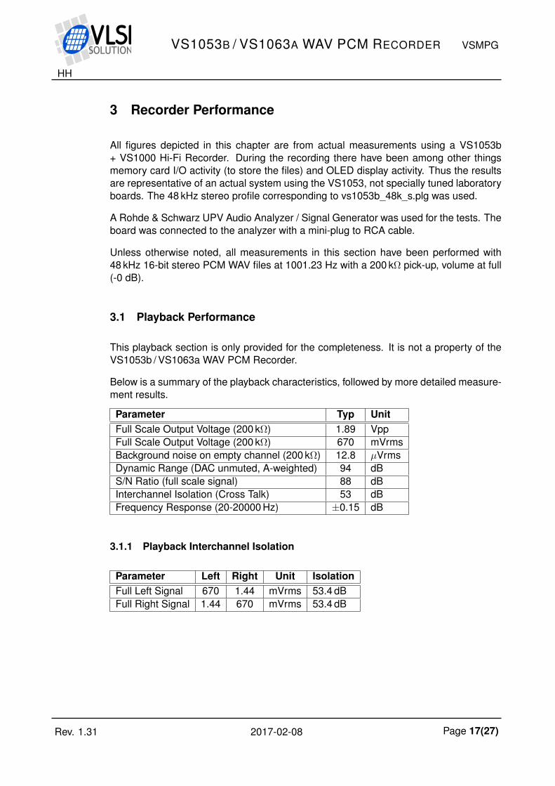
3.1 Playback Performance
This playback section is only provided for the completeness. It is not a property of theVS1053b / VS1063a WAV PCM Recorder.
Below is a summary of the playback characteristics, followed by more detailed measure-ment results.
Parameter Typ UnitFull Scale Output Voltage (200 kΩ) 1.89 VppFull Scale Output Voltage (200 kΩ) 670 mVrmsBackground noise on empty channel (200 kΩ) 12.8 µVrmsDynamic Range (DAC unmuted, A-weighted) 94 dBS/N Ratio (full scale signal) 88 dBInterchannel Isolation (Cross Talk) 53 dBFrequency Response (20-20000 Hz) ±0.15 dB
3.1.1 Playback Interchannel Isolation
Parameter Left Right Unit IsolationFull Left Signal 670 1.44 mVrms 53.4 dBFull Right Signal 1.44 670 mVrms 53.4 dB
Rev. 1.31 2017-02-08 Page 17(27)
HH
VS1053B / VS1063A WAV PCM RECORDER VSMPG
3.1.2 Playback Noise and THD Ratios
Signal / dB SN+THD / dB S/N / dB THD / dB0 66.9 88.7 68.0
-1 67.8 88.1 68.8-2 68.6 88.2 69.6-3 69.3 87.6 70.4-4 70.0 87.3 71.1-5 70.7 86.8 71.8-6 71.4 86.3 72.5-8 73.1 84.7 74.3
-10 74.6 83.0 76.2-12 76.1 81.3 78.1-15 76.6 78.3 81.0-18 75.0 75.5 81.3-24 69.4 69.5 77.7-30 63.5 63.5 71.0-36 57.6 57.7 65.0-42 51.5 51.5 60.0-48 45.5 45.7 53.0-54 39.6 39.5 47.0-60 33.4 33.5 41.0-66 27.5 27.7 35.0-72 22.0 22.2 29.0-78 16.5 16.5 24.0
0 10 20 30 40 50 60 700
10
20
30
40
50
60
70
80
90
100USB HiFi Recorder: Output signal and noise + distortion, A weighted
1001.23 Hz sine signal attenuation / dB
Ra
tio
/ d
B
Signal to Noise + Tot.Harm.Dist. ratio (SN+THD)Signal−to−Noise ratio (N) Signal to Total Harmonic Distortion ratio (THD)
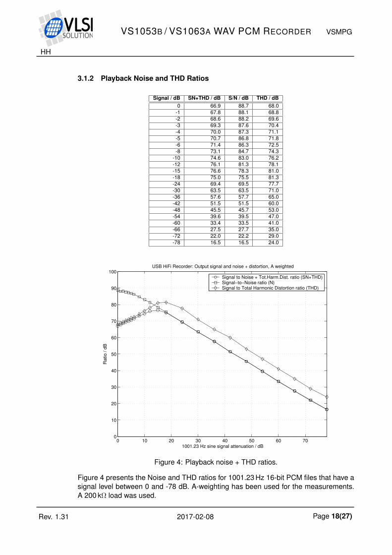
Figure 4: Playback noise + THD ratios.
Figure 4 presents the Noise and THD ratios for 1001.23 Hz 16-bit PCM files that have asignal level between 0 and -78 dB. A-weighting has been used for the measurements.A 200 kΩ load was used.
Rev. 1.31 2017-02-08 Page 18(27)
HH
VS1053B / VS1063A WAV PCM RECORDER VSMPG
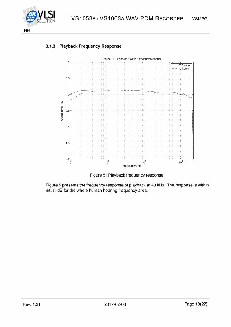
3.1.3 Playback Frequency Response
101
102
103
104
−2
−1.5
−1
−0.5
0
0.5
1Stereo HiFi Recorder: Output freqency response
Frequency / Hz
Ou
tpu
t le
ve
l /
dB
200 kohm10 kohm
Figure 5: Playback frequency response.
Figure 5 presents the frequency response of playback at 48 kHz. The response is within±0.15 dB for the whole human hearing frequency area.
Rev. 1.31 2017-02-08 Page 19(27)
HH
VS1053B / VS1063A WAV PCM RECORDER VSMPG
3.2 Recording Performance
Unless otherwise noted, all measurements in this section have been performed with the48 kHz 16-bit stereo PCM WAV profile with a test frequency of 1001.23 Hz, line input witha 10 Ω drive from the signal generator, at unity gain (SCI_AICTRL1 = 1024). Resulting16-bit stereo output files have then been analyzed with MatLab.
Parameter Typ UnitMaximum Amplitude 3100 mVpp ACTotal Harmonic Distortion 0.013 %S/N Ratio 86 dBDynamic Range 95 dBInterchannel Isolation (Cross Talk) 95 dBImpedance 80 kΩ
Frequency Response (20-20000 Hz) ±0.8 dBFrequency Response (70-20000 Hz) ±0.1 dB
Rev. 1.31 2017-02-08 Page 20(27)
HH
VS1053B / VS1063A WAV PCM RECORDER VSMPG
3.2.1 Recording Noise and THD Ratios
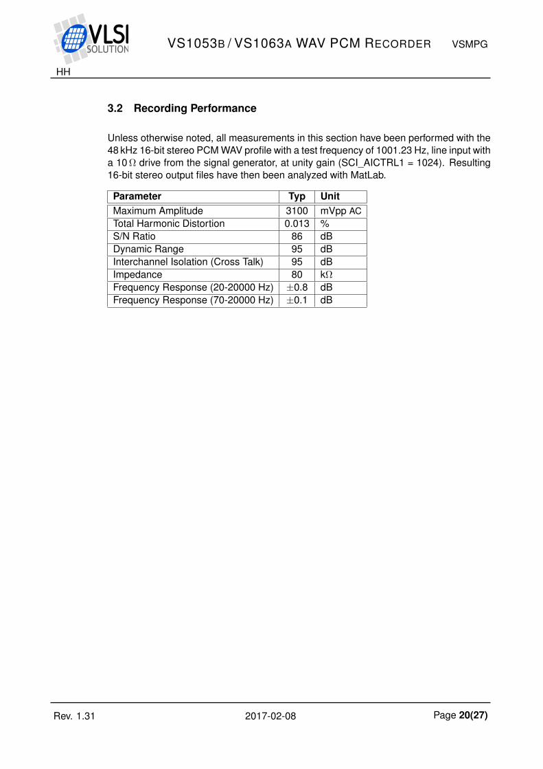
Signal / dB SN+THD / dB S/N / dB THD / dB2.1 21.6 43.2 21.61.5 26.3 50.2 26.30.8 39.1 50.7 39.40.0 76.7 86.3 77.3
-0.8 76.3 84.5 76.9-3.9 73.3 83.5 73.7-6.8 71.4 83.6 71.6
-12.9 66.1 79.7 66.3-18.9 65.9 74.4 66.6-24.7 66.4 69.0 69.8-30.7 62.6 63.4 71.9-36.7 57.0 57.5 66.3-42.8 51.2 51.3 65.1-48.8 44.6 44.8 58.5-54.8 38.4 38.4 59.6-60.8 32.1 32.1 50.5-66.8 26.6 26.7 43.8-72.9 21.1 21.2 38.0-78.9 15.3 15.4 32.7-84.7 9.5 9.5 33.2-90.7 3.5 3.5 31.9-96.7 -2.5 -2.5 26.7
-102.8 -8.7 -8.7 19.8
0 10 20 30 40 50 60 70 80 90 1000
10
20
30
40
50
60
70
80
90
100Stereo HiFi Recorder: Noise + Tot.harm.dist. ratios, A weighted
1001.23 Hz sine signal attenuation / dB
Ra
tio
/ d
B
Signal to Noise + THDSignal to Noise Signal to THD
Figure 6: Recording noise + THD ratios.
Figure 6 shows the Noise and THD ratios of recording a 1001.23 Hz sine signal at differ-ent signal levels. 0 dB level is 1.1 V(rms), or 3.1 Vpp. The A-weighting curve has beenused.
Rev. 1.31 2017-02-08 Page 21(27)
HH
VS1053B / VS1063A WAV PCM RECORDER VSMPG
3.2.2 Recording Frequency Response
101
102
103
104
−2
−1.5
−1
−0.5
0
0.5
1Stereo HiFi Recorder: Input frequency response
Frequency / Hz
Am
plit
ude / d
B
Frequency response
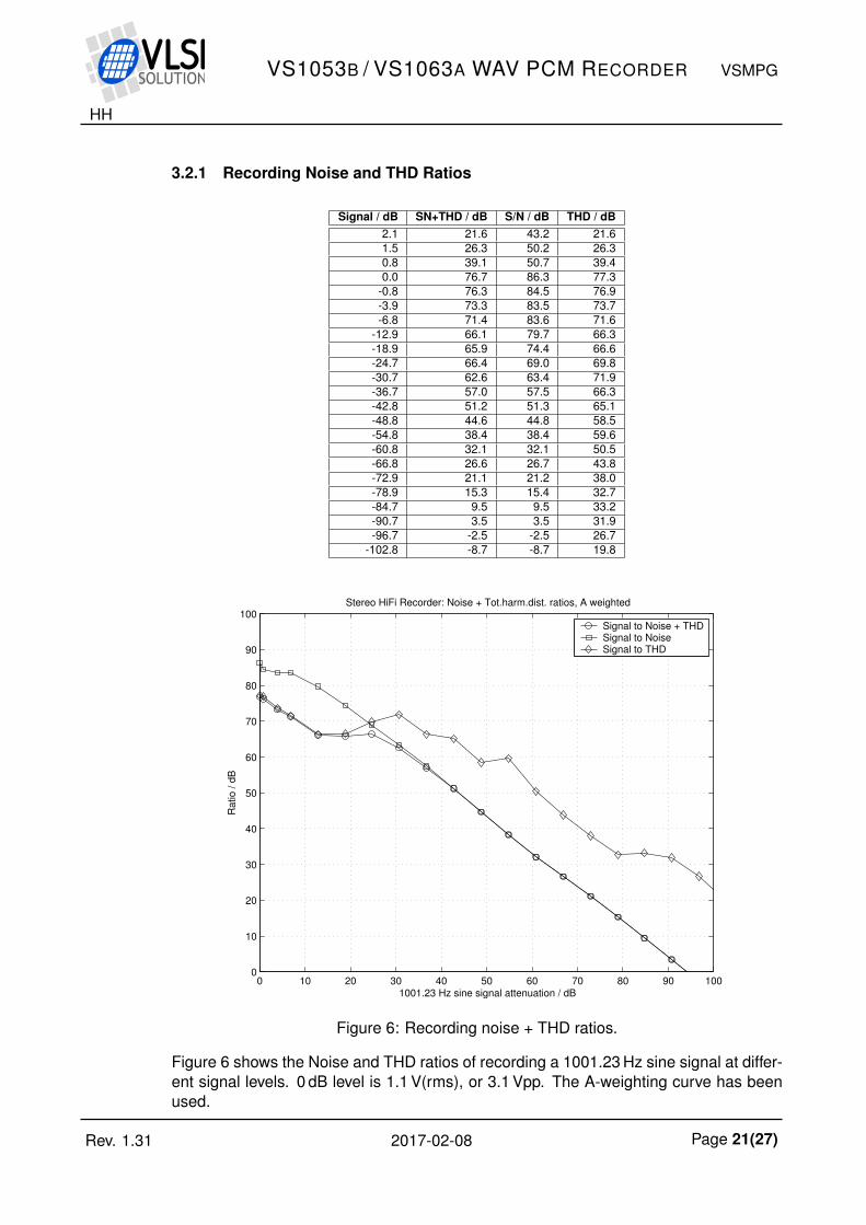
Figure 7: Recording frequency response.
0 0.5 1 1.5 2
x 104
−70
−60
−50
−40
−30
−20
−10
0
Stereo HiFi Recorder: Input frequency response and image rejection
Frequency / Hz
Am
plit
ude / d
B
Frequency response Image rejection frequency response
Figure 8: Recording image rejection frequency response.
Figure 7 presents recording frequency response and Figure 8 image rejection.
Rev. 1.31 2017-02-08 Page 22(27)
HH
VS1053B / VS1063A WAV PCM RECORDER VSMPG
3.2.3 Recording Monitor Frequency Response
101
102
103
104
−2
−1.5
−1
−0.5
0
0.5
1Stereo HiFi Recorder: Monitor frequency response
Frequency / Hz
Am
plit
ude / d
B
Frequency response
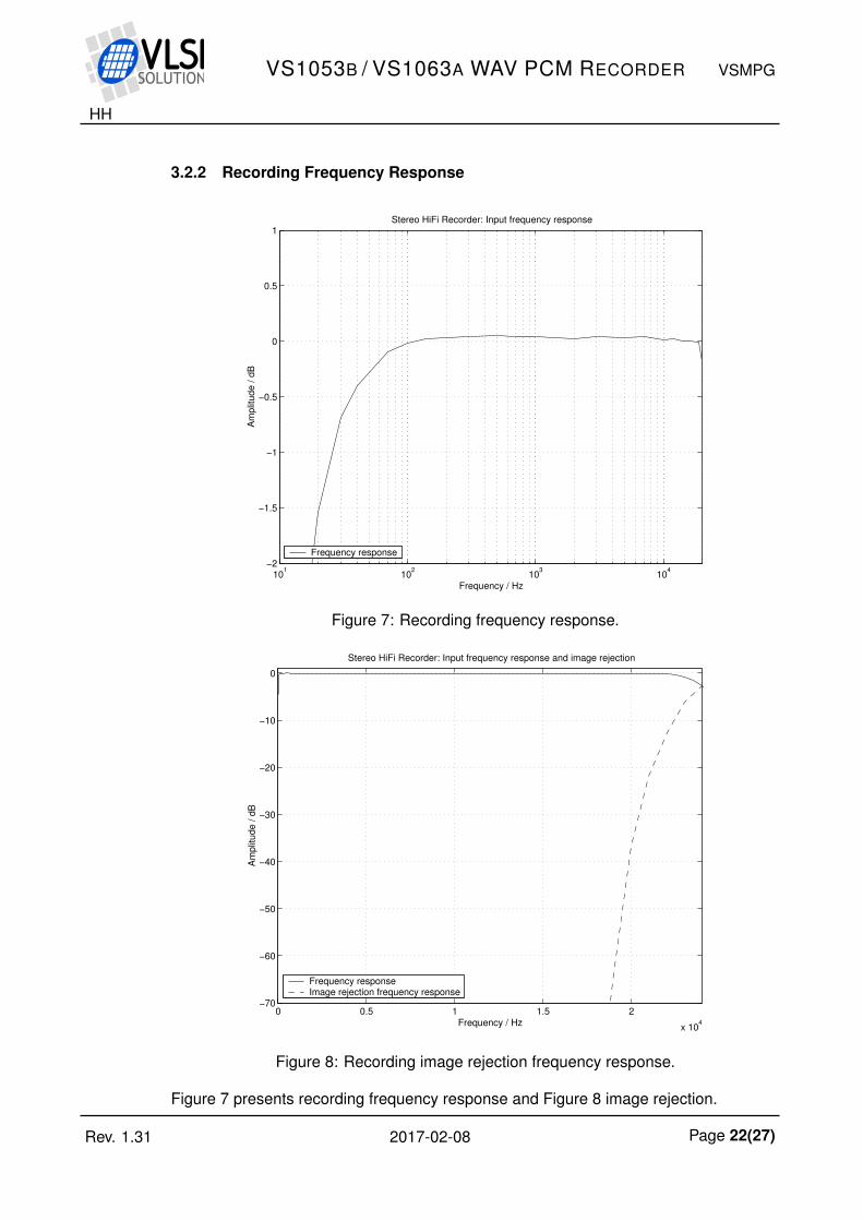
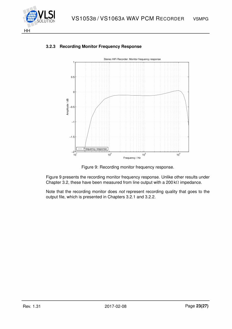
Figure 9: Recording monitor frequency response.
Figure 9 presents the recording monitor frequency response. Unlike other results underChapter 3.2, these have been measured from line output with a 200 kΩ impedance.
Note that the recording monitor does not represent recording quality that goes to theoutput file, which is presented in Chapters 3.2.1 and 3.2.2.
Rev. 1.31 2017-02-08 Page 23(27)
HH
VS1053B / VS1063A WAV PCM RECORDER VSMPG
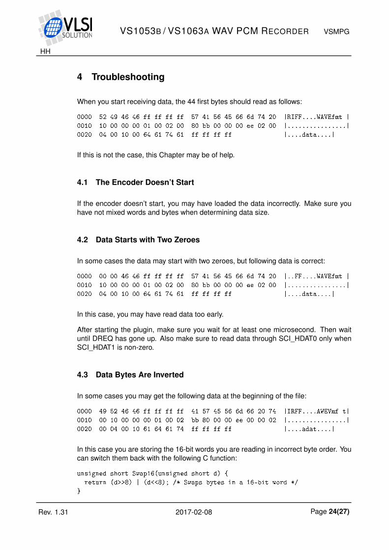
4 Troubleshooting
When you start receiving data, the 44 first bytes should read as follows:
0000 52 49 46 46 ff ff ff ff 57 41 56 45 66 6d 74 20 |RIFF....WAVEfmt |
0010 10 00 00 00 01 00 02 00 80 bb 00 00 00 ee 02 00 |................|
0020 04 00 10 00 64 61 74 61 ff ff ff ff |....data....|
If this is not the case, this Chapter may be of help.
4.1 The Encoder Doesn’t Start
If the encoder doesn’t start, you may have loaded the data incorrectly. Make sure youhave not mixed words and bytes when determining data size.
4.2 Data Starts with Two Zeroes
In some cases the data may start with two zeroes, but following data is correct:
0000 00 00 46 46 ff ff ff ff 57 41 56 45 66 6d 74 20 |..FF....WAVEfmt |
0010 10 00 00 00 01 00 02 00 80 bb 00 00 00 ee 02 00 |................|
0020 04 00 10 00 64 61 74 61 ff ff ff ff |....data....|
In this case, you may have read data too early.
After starting the plugin, make sure you wait for at least one microsecond. Then waituntil DREQ has gone up. Also make sure to read data through SCI_HDAT0 only whenSCI_HDAT1 is non-zero.
4.3 Data Bytes Are Inverted
In some cases you may get the following data at the beginning of the file:
0000 49 52 46 46 ff ff ff ff 41 57 45 56 6d 66 20 74 |IRFF....AWEVmf t|
0010 00 10 00 00 00 01 00 02 bb 80 00 00 ee 00 00 02 |................|
0020 00 04 00 10 61 64 61 74 ff ff ff ff |....adat....|
In this case you are storing the 16-bit words you are reading in incorrect byte order. Youcan switch them back with the following C function:
unsigned short Swap16(unsigned short d)
return (d>>8) | (d<<8); /* Swaps bytes in a 16-bit word */
Rev. 1.31 2017-02-08 Page 24(27)
HH
VS1053B / VS1063A WAV PCM RECORDER VSMPG
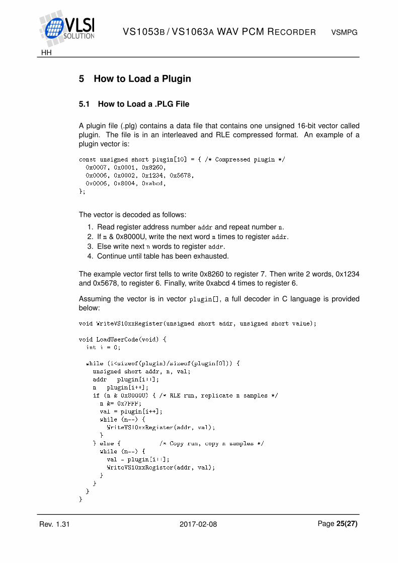
5 How to Load a Plugin
5.1 How to Load a .PLG File
A plugin file (.plg) contains a data file that contains one unsigned 16-bit vector calledplugin. The file is in an interleaved and RLE compressed format. An example of aplugin vector is:
const unsigned short plugin[10] = /* Compressed plugin */
0x0007, 0x0001, 0x8260,
0x0006, 0x0002, 0x1234, 0x5678,
0x0006, 0x8004, 0xabcd,
;
The vector is decoded as follows:
1. Read register address number addr and repeat number n.2. If n & 0x8000U, write the next word n times to register addr.3. Else write next n words to register addr.4. Continue until table has been exhausted.
The example vector first tells to write 0x8260 to register 7. Then write 2 words, 0x1234and 0x5678, to register 6. Finally, write 0xabcd 4 times to register 6.
Assuming the vector is in vector plugin[], a full decoder in C language is providedbelow:
void WriteVS10xxRegister(unsigned short addr, unsigned short value);
void LoadUserCode(void)
int i = 0;
while (i<sizeof(plugin)/sizeof(plugin[0]))
unsigned short addr, n, val;
addr = plugin[i++];
n = plugin[i++];
if (n & 0x8000U) /* RLE run, replicate n samples */
n &= 0x7FFF;
val = plugin[i++];
while (n--)
WriteVS10xxRegister(addr, val);
else /* Copy run, copy n samples */
while (n--)
val = plugin[i++];
WriteVS10xxRegister(addr, val);
Rev. 1.31 2017-02-08 Page 25(27)
HH
VS1053B / VS1063A WAV PCM RECORDER VSMPG
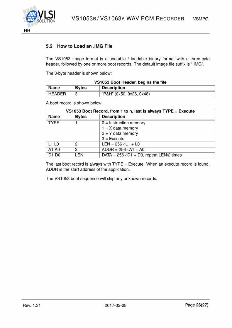
5.2 How to Load an .IMG File
The VS1053 image format is a bootable / loadable binary format with a three-byteheader, followed by one or more boot records. The default image file suffix is “.IMG”.
The 3-byte header is shown below:
VS1053 Boot Header, begins the fileName Bytes DescriptionHEADER 3 “P&H” (0x50, 0x26, 0x48)
A boot record is shown below:
VS1053 Boot Record, from 1 to n, last is always TYPE = ExecuteName Bytes DescriptionTYPE 1 0 = Instruction memory
1 = X data memory2 = Y data memory3 = Execute
L1 L0 2 LEN = 256×L1 + L0A1 A0 2 ADDR = 256×A1 + A0D1 D0 LEN DATA = 256×D1 + D0, repeat LEN/2 times
The last boot record is always with TYPE = Execute. When an execute record is found,ADDR is the start address of the application.
The VS1053 boot sequence will skip any unknown records.
Rev. 1.31 2017-02-08 Page 26(27)
HH
VS1053B / VS1063A WAV PCM RECORDER VSMPG
6 Contact Information
VLSI Solution OyEntrance G, 2nd floor
Hermiankatu 8FI-33720 Tampere
FINLAND
URL: http://www.vlsi.fi/Phone: +358-50-462-3200
Commercial e-mail: [email protected]
For technical support or suggestions regarding this document, please participate athttp://www.vsdsp-forum.com/
For confidential technical discussions, [email protected]
Rev. 1.31 2017-02-08 Page 27(27)