VS 212 TRANSMIG STEALTH - ESAB equipment/cigweldaeb... · equipment are listed at the end of these...
50
800 IPM 15-100 VS TRANSMIG ® STEALTH VS 212 CC/CV SEMIAUTOMATIC SOLID STATE CONTROLLED WIRE FEEDER Operating Manual Revision: AD Issue Date: February 25, 2010 Manual No.: 0-4949 Operating Features: Art # A-07640
Transcript of VS 212 TRANSMIG STEALTH - ESAB equipment/cigweldaeb... · equipment are listed at the end of these...

800IPM
15-100 VS
TRANSMIG®
STEALTH
VS 212
CC/CV SEMIAUTOMATICSOLID STATE CONTROLLEDWIRE FEEDER
Operating ManualRevision: AD Issue Date: February 25, 2010 Manual No.: 0-4949Operating Features:
Art # A-07640

WE APPRECIATE YOUR BUSINESS!Congratulations on your new Cigweld product. We are proud tohave you as our customer and will strive to provide you with thebest service and reliability in the industry. This product is backedby our extensive warranty and world-wide service network. Tolocate your nearest distributor or service agency call+1300 654 674, or visit us on the web at www.cigweld.com.au.
This Operating Manual has been designed to instruct you on thecorrect use and operation of your Cigweld product. Yoursatisfaction with this product and its safe operation is our ultimateconcern. Therefore please take the time to read the entire manual,especially the Safety Precautions. They will help you to avoidpotential hazards that may exist when working with this product.
YOU ARE IN GOOD COMPANY!The Brand of Choice for Contractors and Fabricators Worldwide.
CIGWELD is the Market Leading Brand of Arc Welding Productsfor Thermadyne Industries Inc. We are a mainline supplier to majorwelding industry sectors in the Asia Pacific and emerging globalmarkets including; Manufacturing, Construction, Mining,Automotive, Engineering, Rural and DIY.
We distinguish ourselves from our competition through market-leading, dependable products that have stood the test of time. Wepride ourselves on technical innovation, competitive prices,excellent delivery, superior customer service and technical support,together with excellence in sales and marketing expertise.
Above all, we are committed to develop technologically advancedproducts to achieve a safer working environment within the weldingindustry.

! WARNINGS
Read and understand this entire Manual and your employer’s safety practices before installing,operating, or servicing the equipment.
While the information contained in this Manual represents the Manufacturer's best judgement,the Manufacturer assumes no liability for its use.
Cigweld Transmig VS 212 CC/CV Semiautomatic Solid State Controlled Wire FeederInstruction Manual Number 0-4949 for:Part Number: W3512005 (no meters), W3512006 (with meters)
Published by:Thermadyne Industries Inc.82 Benning StreetWest Lebanon, New Hampshire, USA 03784(603) 298-5711
www.cigweld.com.au
Copyright 2007, 2008, 2009 byThermadyne Industries Inc.
All rights reserved.
Reproduction of this work, in whole or in part, without written permission of the publisheris prohibited.
The publisher does not assume and hereby disclaims any liability to any party for anyloss or damage caused by any error or omission in this manual, whether such errorresults from negligence, accident, or any other cause.
Publication Date: February 14, 2007Revision AD Date: February 25, 2010
Record the following information for Warranty purposes:
Where Purchased: ___________________________________
Purchase Date: ___________________________________
Equipment Serial #: ___________________________________
i

TABLE OF CONTENTS (continued)
TABLE OF CONTENTS
SECTION 1:ARC WELDING SAFETY INSTRUCTIONS AND WARNINGS .................................... 1-1
1.01 Arc Welding Hazards ...................................................................................... 1-11.02 PRINCIPAL SAFETY STANDARDS .................................................................. 1-51.03 DECLARATION OF CONFORMITY ................................................................... 1-6
SECTION 2:INTRODUCTION ...................................................................................... 2-1
2.01 How To Use This Manual ................................................................................ 2-12.02 Equipment Identification ................................................................................. 2-12.03 Receipt Of Equipment ..................................................................................... 2-12.04 Symbol Chart ................................................................................................. 2-22.05 General ........................................................................................................... 2-32.06 Product Specifications ................................................................................... 2-42.07 Features/Benefits ............................................................................................ 2-52.08 Front Panel Controls And Connections ........................................................... 2-62.09 Rear Panel Controls And Connections ............................................................ 2-72.10 Internal Controls And Connections ................................................................. 2-82.11 Power Source Compatibility ........................................................................... 2-92.12 Options and Accessories ................................................................................ 2-9
SECTION 3: INSTALLATION ...................................................................................... 3-1
3.01 Connections ................................................................................................... 3-13.02 Installation Of Wire Spool ............................................................................... 3-23.03 Adjustment Of Spool Tension ......................................................................... 3-33.04 Input And Output Wire Guide Installation ....................................................... 3-33.05 Selection And Installation Of Feed Rolls ......................................................... 3-43.06 MIG Gun Compatibility And Installation and Removal .................................... 3-43.07 Threading Wire Into Feedhead ........................................................................ 3-5
SECTION 4:OPERATION........................................................................................... 4-1
4.01 Prewelding Procedure .................................................................................... 4-14.02 Welding Procedure ......................................................................................... 4-24.03 Welding In CC Mode vs. CV Mode .................................................................. 4-24.04 Theory Of Operation ....................................................................................... 4-24.05 Adjusting Burnback Time ............................................................................... 4-34.06 Wire Feed Speed Ranges ................................................................................ 4-34.07 Changing Meter Functions .............................................................................. 4-44.08 Meter Hold Function ....................................................................................... 4-54.09 Operation Hours Display................................................................................. 4-54.10 Protection And Safety Circuits ........................................................................ 4-5
TABLE OF CONTENTS
SECTION 5: SERVICE ............................................................................................. 5-1
5.01 Cleaning Of The Unit ....................................................................................... 5-15.02 Cleaning Of The Feed Rolls ............................................................................. 5-15.03 Troubleshooting Guide ................................................................................... 5-15.04 Troubleshooting Hints .................................................................................... 5-15.05 Common Symptoms ...................................................................................... 5-1
SECTION 6:PARTS LIST .......................................................................................... 6-1
6.01 Equipment Identification ................................................................................. 6-16.02 How To Use This Parts List ............................................................................ 6-16.03 External Replacement Parts ............................................................................ 6-26.04 Internal Replacement Parts ............................................................................ 6-36.05 Wire Feeder Replacement Parts ..................................................................... 6-4
APPENDIX 1:DRIVE ROLL KITS ................................................................................... A-1
APPENDIX 2:OPTIONS AND ACCESSORIES ..................................................................... A-2
APPENDIX 3:MIG GUN CARTRIDGE SYSTEM ................................................................... A-3
APPENDIX 4:SYSTEM SCHEMATIC ............................................................................... A-4
Statement of Warranty
Warranty SCHEDULE
GLOBAL CUSTOMER SERVICE CONTACT INFORMATION .......................... Inside Rear Cover
TRANSMIG VS 212
Manual No. 0-4949 1-1 SAFETY INSTRUCTIONS
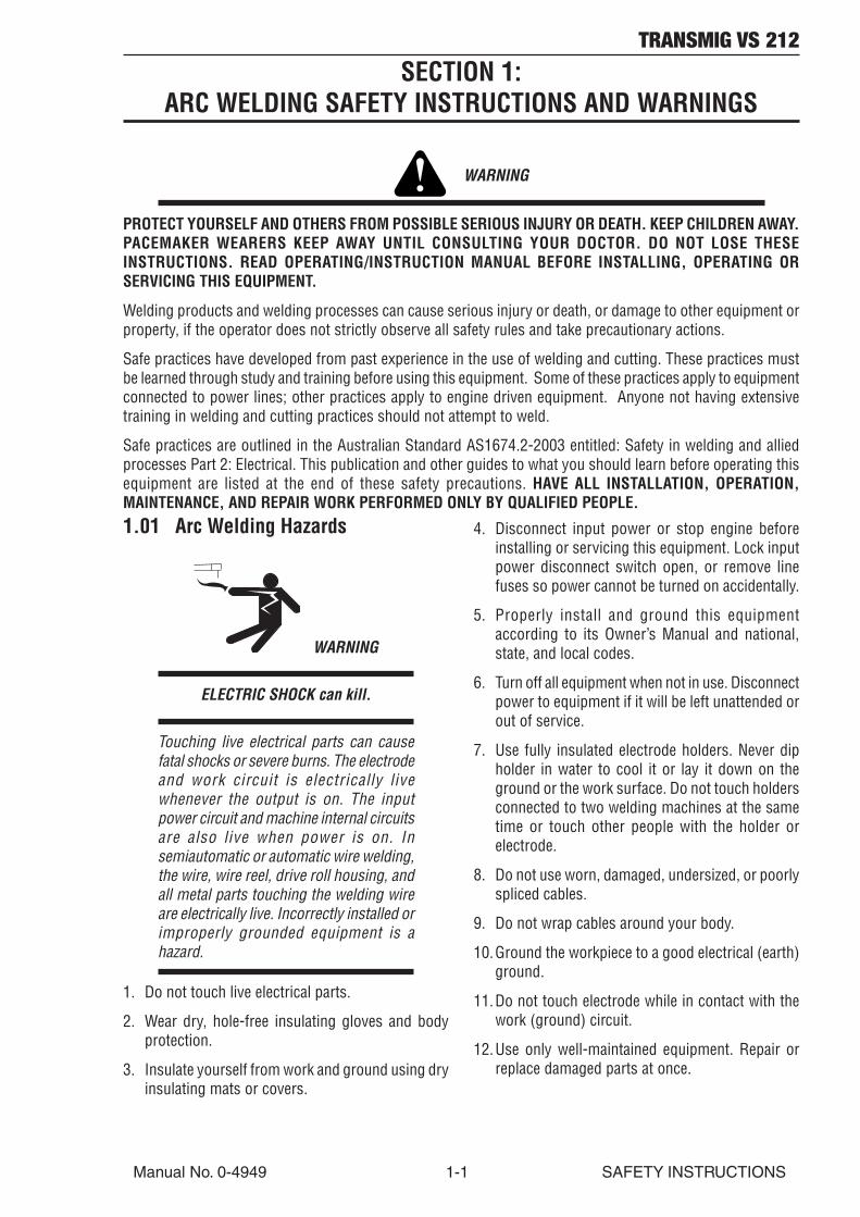
1.01 Arc Welding Hazards
WARNING
ELECTRIC SHOCK can kill.
Touching live electrical parts can causefatal shocks or severe burns. The electrodeand work circuit is electrically livewhenever the output is on. The inputpower circuit and machine internal circuitsare also live when power is on. Insemiautomatic or automatic wire welding,the wire, wire reel, drive roll housing, andall metal parts touching the welding wireare electrically live. Incorrectly installed orimproperly grounded equipment is ahazard.
1. Do not touch live electrical parts.
2. Wear dry, hole-free insulating gloves and bodyprotection.
3. Insulate yourself from work and ground using dryinsulating mats or covers.
4. Disconnect input power or stop engine beforeinstalling or servicing this equipment. Lock inputpower disconnect switch open, or remove linefuses so power cannot be turned on accidentally.
5. Properly install and ground this equipmentaccording to its Owner’s Manual and national,state, and local codes.
6. Turn off all equipment when not in use. Disconnectpower to equipment if it will be left unattended orout of service.
7. Use fully insulated electrode holders. Never dipholder in water to cool it or lay it down on theground or the work surface. Do not touch holdersconnected to two welding machines at the sametime or touch other people with the holder orelectrode.
8. Do not use worn, damaged, undersized, or poorlyspliced cables.
9. Do not wrap cables around your body.
10.Ground the workpiece to a good electrical (earth)ground.
11.Do not touch electrode while in contact with thework (ground) circuit.
12.Use only well-maintained equipment. Repair orreplace damaged parts at once.
SECTION 1:ARC WELDING SAFETY INSTRUCTIONS AND WARNINGS
WARNING
PROTECT YOURSELF AND OTHERS FROM POSSIBLE SERIOUS INJURY OR DEATH. KEEP CHILDREN AWAY.PACEMAKER WEARERS KEEP AWAY UNTIL CONSULTING YOUR DOCTOR. DO NOT LOSE THESEINSTRUCTIONS. READ OPERATING/INSTRUCTION MANUAL BEFORE INSTALLING, OPERATING ORSERVICING THIS EQUIPMENT.
Welding products and welding processes can cause serious injury or death, or damage to other equipment orproperty, if the operator does not strictly observe all safety rules and take precautionary actions.
Safe practices have developed from past experience in the use of welding and cutting. These practices mustbe learned through study and training before using this equipment. Some of these practices apply to equipmentconnected to power lines; other practices apply to engine driven equipment. Anyone not having extensivetraining in welding and cutting practices should not attempt to weld.
Safe practices are outlined in the Australian Standard AS1674.2-2003 entitled: Safety in welding and alliedprocesses Part 2: Electrical. This publication and other guides to what you should learn before operating thisequipment are listed at the end of these safety precautions. HAVE ALL INSTALLATION, OPERATION,MAINTENANCE, AND REPAIR WORK PERFORMED ONLY BY QUALIFIED PEOPLE.
TRANSMIG VS 212
SAFETY INSTRUCTIONS 1-2 Manual No. 0-4949
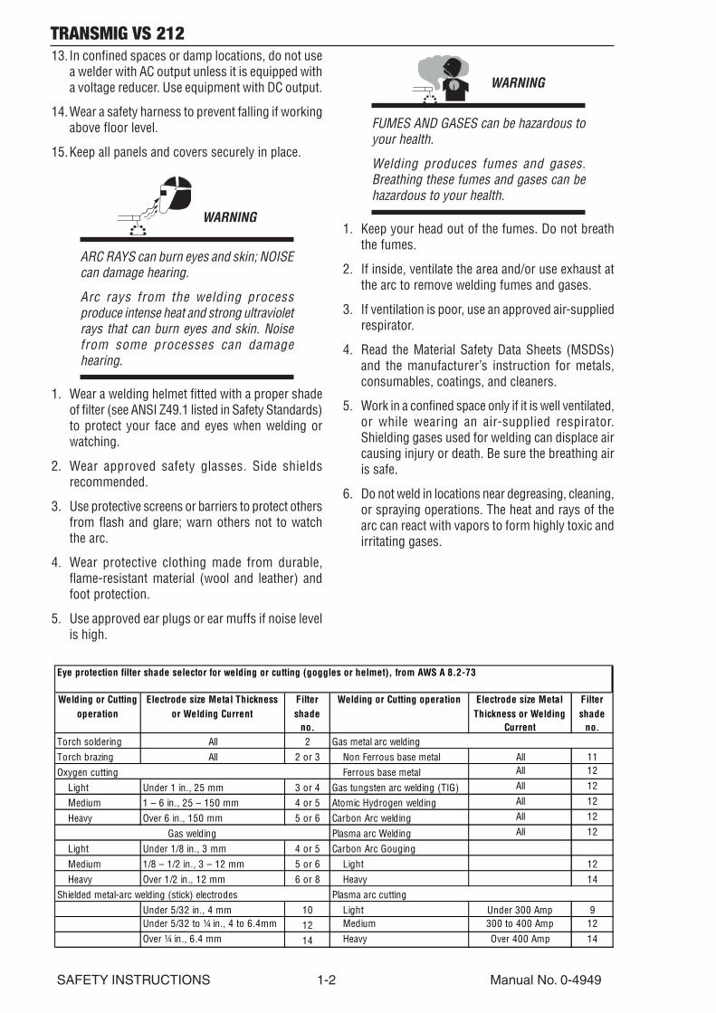
13. In confined spaces or damp locations, do not usea welder with AC output unless it is equipped witha voltage reducer. Use equipment with DC output.
14.Wear a safety harness to prevent falling if workingabove floor level.
15.Keep all panels and covers securely in place.
WARNING
ARC RAYS can burn eyes and skin; NOISEcan damage hearing.
Arc rays from the welding processproduce intense heat and strong ultravioletrays that can burn eyes and skin. Noisefrom some processes can damagehearing.
1. Wear a welding helmet fitted with a proper shadeof filter (see ANSI Z49.1 listed in Safety Standards)to protect your face and eyes when welding orwatching.
2. Wear approved safety glasses. Side shieldsrecommended.
3. Use protective screens or barriers to protect othersfrom flash and glare; warn others not to watchthe arc.
4. Wear protective clothing made from durable,flame-resistant material (wool and leather) andfoot protection.
5. Use approved ear plugs or ear muffs if noise levelis high.
WARNING
FUMES AND GASES can be hazardous toyour health.
Welding produces fumes and gases.Breathing these fumes and gases can behazardous to your health.
1. Keep your head out of the fumes. Do not breaththe fumes.
2. If inside, ventilate the area and/or use exhaust atthe arc to remove welding fumes and gases.
3. If ventilation is poor, use an approved air-suppliedrespirator.
4. Read the Material Safety Data Sheets (MSDSs)and the manufacturer’s instruction for metals,consumables, coatings, and cleaners.
5. Work in a confined space only if it is well ventilated,or while wearing an air-supplied respirator.Shielding gases used for welding can displace aircausing injury or death. Be sure the breathing airis safe.
6. Do not weld in locations near degreasing, cleaning,or spraying operations. The heat and rays of thearc can react with vapors to form highly toxic andirritating gases.
Welding or Cutting operation
Electrode size Metal Thickness or Welding Current
Filter shade
no.
Welding or Cutting operation Electrode size Metal Thickness or Welding
Current
Filter shade
no.Torch soldering All 2Torch brazing All 2 or 3 Non Ferrous base metal All 11
Ferrous base metal All 12
Light Under 1 in., 25 mm 3 or 4 Gas tungsten arc welding (TIG) All 12
Medium 1 – 6 in., 25 – 150 mm 4 or 5 Atomic Hydrogen welding All 12
Heavy Over 6 in., 150 mm 5 or 6 Carbon Arc welding All 12
Plasma arc Welding All 12
Light Under 1/8 in., 3 mm 4 or 5 Carbon Arc GougingMedium 1/8 – 1/2 in., 3 – 12 mm 5 or 6 Light 12Heavy Over 1/2 in., 12 mm 6 or 8 Heavy 14
Under 5/32 in., 4 mm 10 Light Under 300 Amp 9Under 5/32 to ¼ in., 4 to 6.4mm 12 Medium 300 to 400 Amp 12Over ¼ in., 6.4 mm 14 Heavy Over 400 Amp 14
Eye protection filter shade selector for welding or cutting (goggles or helmet), from AWS A 8.2-73
Plasma arc cutting
Oxygen cutting
Gas metal arc welding
Gas welding
Shielded metal-arc welding (stick) electrodes
TRANSMIG VS 212
Manual No. 0-4949 1-3 SAFETY INSTRUCTIONS
7. Do not weld on coated metals, such as galvanized,lead, or cadmium plated steel, unless the coatingis removed from the weld area, the area is wellventilated, and if necessary, while wearing an air-supplied respirator. The coatings and any metalscontaining these elements can give off toxic fumesif welded.
WARNING
WELDING can cause fire or explosion.
Sparks and spatter fly off from the weldingarc. The flying sparks and hot metal, weldspatter, hot workpiece, and hot equipmentcan cause fires and burns. Accidentalcontact of electrode or welding wire tometal objects can cause sparks,overheating, or fire.
1. Protect yourself and others from flying sparks andhot metal.
2. Do not weld where flying sparks can strikeflammable material.
3. Remove all flammables within 35 ft (10.7 m) ofthe welding arc. If this is not possible, tightly coverthem with approved covers.
4. Be alert that welding sparks and hot materials fromwelding can easily go through small cracks andopenings to adjacent areas.
5. Watch for fire, and keep a fire extinguisher nearby.
6. Be aware that welding on a ceiling, floor, bulkhead,or partition can cause fire on the hidden side.
7. Do not weld on closed containers such as tanksor drums.
8. Connect work cable to the work as close to thewelding area as practical to prevent weldingcurrent from traveling long, possibly unknownpaths and causing electric shock and fire hazards.
9. Do not use welder to thaw frozen pipes.
10.Remove stick electrode from holder or cut offwelding wire at contact tip when not in use.
WARNING
FLYING SPARKS AND HOT METAL cancause injury.
Chipping and grinding cause flying metal.As welds cool, they can throw off slag.
1. Wear approved face shield or safety goggles. Sideshields recommended.
2. Wear proper body protection to protect skin.
WARNING
CYLINDERS can explode if damaged.
Shielding gas cylinders contain gas underhigh pressure. If damaged, a cylinder canexplode. Since gas cylinders are normallypart of the welding process, be sure totreat them carefully.
1. Protect compressed gas cylinders from excessiveheat, mechanical shocks, and arcs.
2. Install and secure cylinders in an upright positionby chaining them to a stationary support orequipment cylinder rack to prevent falling ortipping.
3. Keep cylinders away from any welding or otherelectrical circuits.
4. Never allow a welding electrode to touch anycylinder.
5. Use only correct shielding gas cylinders,regulators, hoses, and fittings designed for thespecific application; maintain them and associatedparts in good condition.
6. Turn face away from valve outlet when openingcylinder valve.
7. Keep protective cap in place over valve exceptwhen cylinder is in use or connected for use.
8. Read and follow instructions on compressed gascylinders, associated equipment, and CGApublication P-1 listed in Safety Standards.
TRANSMIG VS 212
SAFETY INSTRUCTIONS 1-4 Manual No. 0-4949
WARNING
Engines can be dangerous.
WARNING
ENGINE EXHAUST GASES can kill.
Engines produce harmful exhaust gases.
1. Use equipment outside in open, well-ventilatedareas.
2. If used in a closed area, vent engine exhaustoutside and away from any building air intakes.
WARNING
ENGINE FUEL can cause fire or explosion.
Engine fuel is highly flammable.
1. Stop engine before checking or adding fuel.
2. Do not add fuel while smoking or if unit is nearany sparks or open flames.
3. Allow engine to cool before fueling. If possible,check and add fuel to cold engine before beginningjob.
4. Do not overfill tank — allow room for fuel toexpand.
5. Do not spill fuel. If fuel is spilled, clean up beforestarting engine.
WARNING
MOVING PARTS can cause injury.
Moving parts, such as fans, rotors, and belts can cutfingers and hands and catch loose clothing.
1. Keep all doors, panels, covers, and guardsclosed and securely in place.
2. Stop engine before installing or connectingunit.
3. Have only qualified people remove guards orcovers for maintenance and troubleshootingas necessary.
4. To prevent accidental starting duringservicing, disconnect negative (-) batterycable from battery.
5. Keep hands, hair, loose clothing, and toolsaway from moving parts.
6. Reinstall panels or guards and close doorswhen servicing is finished and before startingengine.
WARNING
SPARKS can cause BATTERY GASES TOEXPLODE; BATTERY ACID can burn eyesand skin.
Batteries contain acid and generate explosive gases.
1. Always wear a face shield when working on abattery.
2. Stop engine before disconnecting or connectingbattery cables.
3. Do not allow tools to cause sparks when workingon a battery.
4. Do not use welder to charge batteries or jump startvehicles.
5. Observe correct polarity (+ and –) on batteries.

TRANSMIG VS 212
Manual No. 0-4949 1-5 SAFETY INSTRUCTIONS
WARNING
STEAM AND PRESSURIZED HOTCOOLANT can burn face, eyes, and skin.
The coolant in the radiator can be very hotand under pressure.
1. Do not remove radiator cap when engine is hot.Allow engine to cool.
2. Wear gloves and put a rag over cap area whenremoving cap.
3. Allow pressure to escape before completelyremoving cap.
WARNING
This product, when used for welding orcutting, produces fumes or gases whichcontain chemicals know to the State ofCalifornia to cause birth defects and, insome cases, cancer. (California Health &Safety code Sec. 25249.5 et seq.)
NOTE
Considerations About Welding And TheEffects of Low Frequency Electric andMagnetic Fields
The following is a quotation from the GeneralConclusions Section of the U.S. Congress, Office ofTechnology Assessment, Biological Effects of PowerFrequency Electric & Magnetic Fields - BackgroundPaper, OTA-BP-E-63 (Washington, DC: U.S.Government Printing Office, May 1989): “...there isnow a very large volume of scientific findings basedon experiments at the cellular level and from studieswith animals and people which clearly establish thatlow frequency magnetic fields and interact with, andproduce changes in, biological systems. While mostof this work is of very high quality, the results arecomplex. Current scientific understanding does notyet allow us to interpret the evidence in a singlecoherent framework. Even more frustrating, it doesnot yet allow us to draw definite conclusions aboutquestions of possible risk or to offer clear science-based advice on strategies to minimize or avoidpotential risks.”
To reduce magnetic fields in the workplace, use thefollowing procedures.
1. Keep cables close together by twisting ortaping them.
2. Arrange cables to one side and away from theoperator.
3. Do not coil or drape cable around the body.
4. Keep welding power source and cables as faraway from body as practical.
ABOUT PACEMAKERS:
The above procedures are among thosealso normally recommended forpacemaker wearers. Consult your doctorfor complete information.
1.02 PRINCIPAL SAFETY STANDARDS
Safety in Welding and Cutting, ANSI Standard Z49.1,from American Welding Society, 550 N.W. LeJeuneRd., Miami, FL 33126.
Safety and Health Standards, OSHA 29 CFR 1910,from Superintendent of Documents, U.S. GovernmentPrinting Office, Washington, D.C. 20402.
Recommended Safe Practices for the Preparation forWelding and Cutting of Containers That Have HeldHazardous Substances, American Welding SocietyStandard AWS F4.1, from American Welding Society,550 N.W. LeJeune Rd., Miami, FL 33126.
National Electrical Code, NFPA Standard 70, fromNational Fire Protection Association, BatterymarchPark, Quincy, MA 02269.
Safe Handling of Compressed Gases in Cylinders, CGAPamphlet P-1, from Compressed Gas Association,1235 Jefferson Davis Highway, Suite 501, Arlington,VA 22202.
Code for Safety in Welding and Cutting, CSA StandardW117.2, from Canadian Standards Association,Standards Sales, 178 Rexdale Boulevard, Rexdale,Ontario, Canada M9W 1R3.
Safe Practices for Occupation and Educational Eyeand Face Protection, ANSI Standard Z87.1, fromAmerican National Standards Institute, 1430Broadway, New York, NY 10018.
Cutting and Welding Processes, NFPA Standard 51B,from National Fire Protection Association,Batterymarch Park, Quincy, MA 02269.
Safety in welding and allied processes Part 2:Electrical, AS1674.2-2003 from SAI Global Limited,www.saiglobal.com

TRANSMIG VS 212
SAFETY INSTRUCTIONS 1-6 Manual No. 0-4949
1.03 DECLARATION OF CONFORMITY
Manufacturer: CIGWELDAddress: 71 Gower St, Preston
Victoria 3072
Australia
Description of equipment: Welding Equipment (GMAW, MMAW, GTAW, and CAG). Including, but not limited toCIGWELD TRANSMIG 500SP, 400SP, 320SP, VS212 Stealth and associated accessories.
Serial numbers are unique with each individual piece of equipment and details description, partsused to manufacture a unit and date of manufacture.
The equipment conforms to all applicable aspects and regulations of the ‘Low Voltage Directive’ (Directive73/23/EU, as recently changed in Directive 93/68/EU and to the National legislation for the enforcement of theDirective.
National Standard and Technical Specifications
The product is designed and manufactured to a number of standards and technical requirements among themare:
• AS/NZS 3652-(EMC Directive EN50199) applicable to arc welding equipment - generic emissions and
regulations.
• EN60974-1 applicable to welding equipment and associated accessories.
• AS60974.1 applicable to welding equipment and associated accessories.Extensive product design verification is conducted at the manufacturing facility as part of the routine designand manufacturing process, to ensure the product is safe and performs as specified. Rigorous testing isincorporated into the manufacturing process to ensure the manufactured product meets or exceeds all designspecifications.
CIGWELD has been manufacturing and merchandising an extensive equipment range with superior perfor-mance, ultra safe operation and world class quality for more than 30 years and will continue to achieveexcellence.
TRANSMIG VS 212
Manual No. 0-4949 2-1 INTRODUCTION
SECTION 2:INTRODUCTION
2.02 Equipment Identification
The unit’s identification number (specification or partnumber), model, and serial number usually appearon a nameplate attached to the rear panel. In somecases, the nameplate may be attached to the controlpanel. Equipment which does not have a name platesuch as gun and cable assemblies is identified onlyby the specification or part number printed on theshipping container. Record these numbers on thebottom of page i for future reference.
2.03 Receipt Of Equipment
When you receive the equipment, check it againstthe invoice to make sure it is complete and inspectthe equipment for possible damage due to shipping.If there is any damage, notify the carrier immediatelyto file a claim. Furnish complete informationconcerning damage claims or shipping errors to thelocation in your area listed in the inside back cover ofthis manual.
Include all equipment identification numbers asdescribed above along with a full description of theparts in error.
Move the equipment to the installation site before un-crating the unit. Use care to avoid damaging theequipment when using bars, hammers, etc., to un-crate the unit.
2.01 How To Use This Manual
This Owner’s Manual applies to just specification orpart numbers listed on page i.
To ensure safe operation, read the entire manual,including the chapter on safety instructions andwarnings.
Throughout this manual, the words WARNING,CAUTION, and NOTE may appear. Pay particularattention to the information provided under theseheadings. These special annotations are easilyrecognized as follows:
! WARNING
A WARNING gives information regardingpossible personal injury.
CAUTION
A CAUTION refers to possible equipmentdamage.
NOTE
A NOTE offers helpful informationconcerning certain operating procedures.
Additional copies of this manual may be purchasedby contacting Cigweld at the address and phonenumber in your area listed in the inside back cover ofthis manual. Include the Owner’s Manual number andequipment identification numbers.
Electronic copies of this manual can also bedownloaded at no charge in Acrobat PDF format bygoing to the Cigweld web site listed below and clickingon the Literature Library link:
http://www.cigweld.com.au

TRANSMIG VS 212
INTRODUCTION 2-2 Manual No. 0-4949
2.04 Symbol Chart
Note that only some of these symbols will appear on your model.
Gas Tungsten Arc Welding (GTAW)
Air Carbon Arc Cutting (CAC-A)
Constant Current
Constant Voltage Or Constant Potential
High Temperature
Fault Indication
Arc Force
Touch Start (GTAW)
Variable Inductance
Voltage Input
Single Phase
Three Phase
Three Phase Static Frequency Converter-Transformer-Rectifier
Dangerous Voltage
Off
On
Panel/Local
Shielded Metal Arc Welding (SMAW)
Gas Metal Arc Welding (GMAW)
Increase/Decrease
Circuit Breaker
AC Auxiliary Power
Remote
Duty Cycle
Percentage
Amperage
Voltage
Hertz (cycles/sec)
Frequency
Negative
Positive
Direct Current (DC)
Protective Earth (Ground)
Line
Line Connection
Auxiliary Power
Receptacle Rating-Auxiliary Power
Art # A-04130
115V 15A
t
t1
t2
%X
IPM
MPM
t
V
Fuse
Wire Feed Function
Wire Feed Towards Workpiece With Output Voltage Off.
Preflow Time
Postflow Time
Spot Time
Spot Weld Mode
Continuous WeldMode
Press to initiate wirefeed and welding, release to stop.
Purging Of Gas
Inches Per Minute
Meters Per Minute
Welding Gun
Burnback Time
Press and hold for preflow, releaseto start arc. Press to stop arc, andhold for preflow.
4 Step TriggerOperation
2 Step TriggerOperation

TRANSMIG VS 212
Manual No. 0-4949 2-3 INTRODUCTION
2.05 General
The TRANSMIG VS 212 is a portable, solid statecontrolled, voltage sensing wire feeder that operateson arc voltage and can be used with most constantvoltage (CV) and constant current (CC) DC-type powersources. The only connection required between thepower source and the wire feeder is the welding cable.
The unique design of this wire feeder allows operationin a constant wire feed speed mode when used withCV power sources, and in a voltage sensing wire feedspeed mode (wire feed speed varies with respect toarc voltage) when used with CC power sources.
The TRANSMIG VS 212’s steel-reinforced, flame-retardant case totally encloses the solid state controlcircuitry, welding wire, and wire drive system. Ahinged, latched door allows quick and easy access tothe contactor, welding wire, and feedhead assemblythat features quick change, gear-driven drive rolls.
TRANSMIG VS 212 comes with:
• Robust injection molded case
• Changeable MIG gun cartridge system
• Heavy duty contactor
• Internal parts storage
• Power cable and drive rolls
• Gas valve solenoid
The TRANSMIG VS 212, includes the followingfeatures:
1. An on/off rocker switch
2. A wire feed speed control knob
3. A welding gun holder
4. A carrying handle
5. A contactor
6. A gas valve
7. A CC/CV mode switch
8. An input circuit breaker for complete systemprotection
9. An electronic controlled protection circuitry toprotect against an undervoltage, an overvoltage,a voltage spike, a shorted or locked motor, ashorted contactor coil, and a shorted gas valve
10.An electronic controlled dynamic brake
11.An electronic controlled current limit to motor
12.An electronic controlled start circuit for improvedarc starting
13.A low voltage gun trigger circuit for operator safety
14.A drive roll kit
15. In addition to these standard features, theTransmig VS212 also includes a digital display forwire feed speed/amps and arc voltage, with arctime and memory hold.
16.Trigger Hold Switch
The TRANSMIG VS 212 has been designed to complywith IEC 60974-1 (CE), CSA NRTL/C, and NEMA EW3 standards.

TRANSMIG VS 212
INTRODUCTION 2-4 Manual No. 0-4949
2.06 Product Specifications
Input Voltage Range 15-100vdc Maximum Input Current 10 amps
Wire Sizes 0.024 - 5/64'' (0.6 - 2.0 mm)
Max Wire Spool Capacity
12'' (304.8 mm) up to 44 Lbs. (20 kg)
Drive Rolls 2 (Both Gear Driven)
Welding Current (I) 425A @ 60% duty cycle 330A @ 100% duty
Welding Gun Inlet Size (Std) Tweco Style #4 5/8'' (16mm) Nominal
Maximum Shielding Gas Inlet Pressure 100 psi (6.9 bar)
Degree of Protection IP21C Weight (Less wire) 40 lbs (18 kg)
IEC 60974-5 NEMA EW3
Wire Speed Range (dependent on arc voltage)
50-800 IPM (1.27 - 22.86 MPM)
Transmig VS212 Specifications
Approvals
Table 2-1 Specifications
21.3 in.541mm
9.4 in.239mm
15.3 in.289mm
Art # A-07130
Figure 2-1: Dimensional Information
TRANSMIG VS 212
Manual No. 0-4949 2-5 INTRODUCTION
2.07 Features/Benefits
Robust injection molded caseLong lasting and unbreakable.
Changeable MIG gun cartridge systemPatent Pending. No external MIG gun adaptersneeded for other style guns with the integratedcartridge system.
Digital displayMonitor wire speed, amps, volts, arc time andmeter hold. Makes parameter set-up easy.
Heavy duty contactorLonger life on higher amperage applications.
Internal parts storageOn the job storage for drive rolls, tips, nozzles, etc.
Machined feed head & tension armsInsures wire alignment tolerances of ±0.05mm.
Inch switch & purge switch‘Cold’ inching of wire at set wire feed speed andpurging of gas without running wire.
Gun trigger hold (2T/4T)Allows standard or latched gun trigger.
Heavy duty, removable voltage sensing leadAllows storage of lead with less lead breakage.
MIG gun holderA place to hold your MIG gun while not welding.
Lifting eyeAllows for hanging or moving of the feeder over thework area.
Gas valve solenoidControls ‘on/off’ flow of shielding gases.
Wire speed high/low rangeGives a finer dial control of larger diameter fluxcored wires.
Ready to weldSupplied with 1.2ft (360mm) power cable, Dinseconnector and .035/.045in (0.9/1.2mm) drive rollsfor hard/tubular wire. Geared top & bottom driverolls. Excellent traction on the wire.
Quick change drive rollsChange the drive rolls without tools.

TRANSMIG VS 212
INTRODUCTION 2-6 Manual No. 0-4949
(2) Wire Feed Speed Control
(7) Gun Switch Receptacle(9) Welding Gun Cable Connection
(10) Removable MIG Gun Cartridge (Tweco style shown)
(3) Wire Feed Speed/Amp Meter
(4) Arc Voltage Meter
(1) On/Off Power Switch
(5) Inch/Purge Switch
(6) 2T/4T Trigger Mode Selector Switch
(8) Voltage Sensing Receptacle 25mm Dinse
Art # A-07136_AB
1. POWER ON/OFF SWITCH: This switch controlsinput power only to the wire feeder and not to thepower source.
2. WIRE FEED SPEED CONTROL: This knob controlsthe wire feed speed. The wire feed speed controlcan be adjusted during setup or actual welding.
3. WIRE FEED SPEED/AMP METER: The wire feedspeed meter displays the actual wire feed speedoutput of the wire feeder. This meter can bechanged to display the actual amperage output ofthe power source by adjusting the DIP switcheslocated on the edge of the display board insidethe unit. Refer to Section 4.07 for details.
4. ARC VOLTAGE METER: The arc voltage meterdisplays the actual voltage output of the powersource.
5. INCH/PURGE SWITCH: Depressing the INCHportion of the switch will feed wire at a speed setby the WFS control. The wire will not be electricallyhot when using the INCH switch. Depressing thePURGE portion of the switch will allow shieldinggas to flow out of the welding gun without feedingwire.
2.08 Front Panel Controls And Connections
6. TRIGGER HOLD SWITCH: This switch selectseither 2 Step or 4 Step gun switch mode.
7. GUN SWITCH RECEPTACLE: The gun switchreceptacle accepts the welding gun control wires.The gun switch receptacle is where a gun switchclosure is inputted to the wire feeder.
8. VOLTAGE SENSING RECEPTACLE: This receptacleserves as the voltage sensing point for the wire feederand must be connected to the work piece throughthe voltage sensing lead for proper operation. If thevoltage sensing lead from the wire feeder and theweld cable from the power source are not connectedto the work piece, the wire feeder will not work.
9. WELDING GUN CABLE CONNECTION: The weldinggun cable is connected to the wire feeder at thispoint. Connections must be tight; otherwise,arcing or overheating could result.
10.REMOVABLE MIG GUN CARTRIDGE (PatentPending): The whole cartridge is interchangeableto accept competitive types of MIG gunconnections. No external adapters required. SeeAppendix 2 and 3 for installation information andto select the adapter for other MIG Gun styles, ie.Miller®, Lincoln® or Euro.
Figure 2-2: Front Panel Controls and Connections
TRANSMIG VS 212
Manual No. 0-4949 2-7 INTRODUCTION
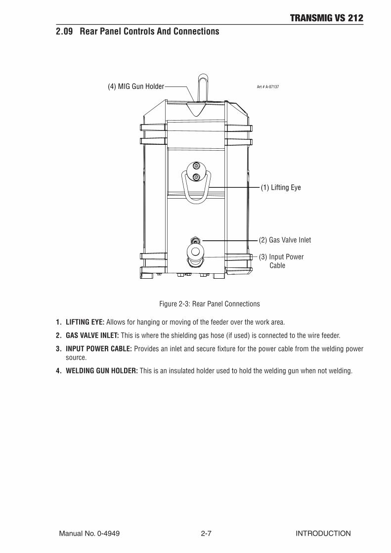
2.09 Rear Panel Controls And Connections
(1) Lifting Eye
(2) Gas Valve Inlet
(3) Input Power Cable
(4) MIG Gun Holder Art # A-07137
Figure 2-3: Rear Panel Connections
1. LIFTING EYE: Allows for hanging or moving of the feeder over the work area.
2. GAS VALVE INLET: This is where the shielding gas hose (if used) is connected to the wire feeder.
3. INPUT POWER CABLE: Provides an inlet and secure fixture for the power cable from the welding powersource.
4. WELDING GUN HOLDER: This is an insulated holder used to hold the welding gun when not welding.

TRANSMIG VS 212
INTRODUCTION 2-8 Manual No. 0-4949
2.10 Internal Controls And Connections
(14) HUB TENSION BOLT
(13) INPUT CIRCUIT BREAKER
(12) CC/CV MODE SWITCH
(2) HIGH/LOW RANGE SWITCH
(11) PRESSURE ADJUST DEVICE(5) UPPER RETAINING KNOB
(7) OUTPUT GUIDE LOCKSCREW
(6) GUN CLAMP KNOB
(8) LOWER RETAINING KNOB
(9) INPUT GUIDE LOCKSCREW
(10) INPUT WIRE GUIDE
Art # A-07138
(1) STORAGE BOX
(3) WIRE SPEED/AMP METER SELECTION DIP SWITCHES
(4) CARTRIDGE GUN LEADS
High
Low
CC
CV
Figure 2-4: Internal Controls and Connections.
1. STORAGE BOX: On the job storage for drive rolls,tips, nozzles, etc. To remove, lift up to releasevelcro and slide it up and over the side retainers.
2. HIGH/LOW RANGE SWITCH: Gives a finer dialcontrol over the wire speed, which is especiallyuseful with larger diameter flux-cored wires.
3. WIRE SPEED/AMP METER SELECTION DIPSWITCHES: Set these switches to change the lowermeter display from wire speed to amperage outputof the power source. Refer to Section 2.08, item 3and section 4.07 for DIP switch setting information.
4. CARTRIDGE GUN LEADS: These two spadeterminals provide the MIG gun switch connection.
5. UPPER RETAINING KNOB: This knob is used tosecure the bearing feed roll. Remove this knob tochange the bearing feed roll.
6. GUN CLAMP KNOB: Tighten this knob to securethe welding gun to the wire feeder.
7. OUTPUT GUIDE LOCKSCREW: Tighten this screwto secure the output wire guide.
8. LOWER RETAINING KNOB: This knob is used tosecure the drive feed roll. Remove this knob tochange the drive feed roll.
9. INPUT GUIDE LOCKSCREW: Tighten this screwto secure the input wire guide.
10.INPUT WIRE GUIDE: This guide is required todirect the welding wire from the wire spool to thedrive feed roll.
11.SPRING TENSION KNOB: Use the spring tensionknob to adjust the amount of force the bearingfeed roll exerts on the welding wire.
TRANSMIG VS 212
Manual No. 0-4949 2-9 INTRODUCTION
12.CC/CV MODE SWITCH: The CC position providesa voltage sensing wire feed speed mode ofoperation for use with constant current (CC) powersources. The CV position provides a constant wirefeed speed mode of operation for use withconstant voltage (CV) power sources.
NOTE
This switch does not select a CC or CVmode of operation. The mode of operationis set by the type of power source beingused.
13.INPUT CIRCUIT BREAKER: This circuit breakerprovides complete system protection for the wirefeeder in the case of a fault or overload condition.
14.HUB TENSION BOLT: The hub tension bolt is usedto adjust the wire spool tension which acts as amechanical brake to assist in the stopping of thewelding wire at the completion of a weld.
2.11 Power Source Compatibility
Since the TRANSMIG VS 212 operates on arc voltage,it will work with most constant current (CC) orconstant voltage (CV) DC type power sources.
When connected to a TRANSMIG VS 212, themaximum allowed open circuit voltage (OCV) of thepower source is 100 VDC. Open circuit voltagesexceeding 100 VDC will damage or shorten the life ofthe unit.
NOTE
Because of the high open circuit voltageassociated with most CC power sources,it is recommended to place the TRANSMIGVS 212 power switch in the OFF positionwhen not welding. This procedure willprolong the life of electrical componentsconnected to the power input lines.
When using the TRANSMIG VS 212, there must be atleast 15 VDC between the output terminals of thepower source during standby and while welding.Otherwise, the unit will not have enough input voltageto operate properly.
A contactor is a standard component of theTRANSMIG VS 212 and allows the welding wire toremain electrically cold until the gun switch trigger isdepressed. This contactor is rated for 425 amps ofwelding current at a 60% duty cycle. If the weldcurrent or duty cycle rating is exceeded, the contactorwill be damaged or its life shortened.
Transarc 250Si, 300SiTranstig 200Pi, 250Pi, 300PiTransmig 500i, 500P, 6045Engine Driven Welders:MPM 5/190, MPM 8/255, MPM 8/270MPM 12/400, MPM 20/500
Compatible CIGWELD Power Sources
2.12 Options and Accessories
Refer to the Appendix section of this manual forthe list of available options and accessories for thisproduct.

TRANSMIG VS 212
INTRODUCTION 2-10 Manual No. 0-4949
NOTES
TRANSMIG VS 212
Manual No. 0-4949 3-1 INSTALLATION
SECTION 3: INSTALLATION
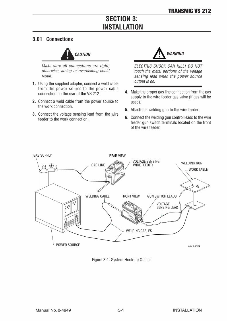
3.01 Connections
CAUTION
Make sure all connections are tight;otherwise, arcing or overheating couldresult.
1. Using the supplied adapter, connect a weld cablefrom the power source to the power cableconnection on the rear of the VS 212.
2. Connect a weld cable from the power source tothe work connection.
3. Connect the voltage sensing lead from the wirefeeder to the work connection.
! WARNING
ELECTRIC SHOCK CAN KILL! DO NOTtouch the metal portions of the voltagesensing lead when the power sourceoutput is on.
4. Make the proper gas line connection from the gassupply to the wire feeder gas valve (if gas will beused).
5. Attach the welding gun to the wire feeder.
6. Connect the welding gun control leads to the wirefeeder gun switch terminals located on the frontof the wire feeder.
+-
VOLTAGE SENSING WELDING GUN
WORK TABLE
VOLTAGESENSING LEAD
WELDING CABLES
WELDING CABLE
GAS LINE
REAR VIEW
POWER SOURCE
FRONT VIEW
GAS SUPPLY
WIRE FEEDER
GUN SWITCH LEADS
Art # A-07194
Figure 3-1: System Hook-up Outline
TRANSMIG VS 212
INSTALLATION 3-2 Manual No. 0-4949
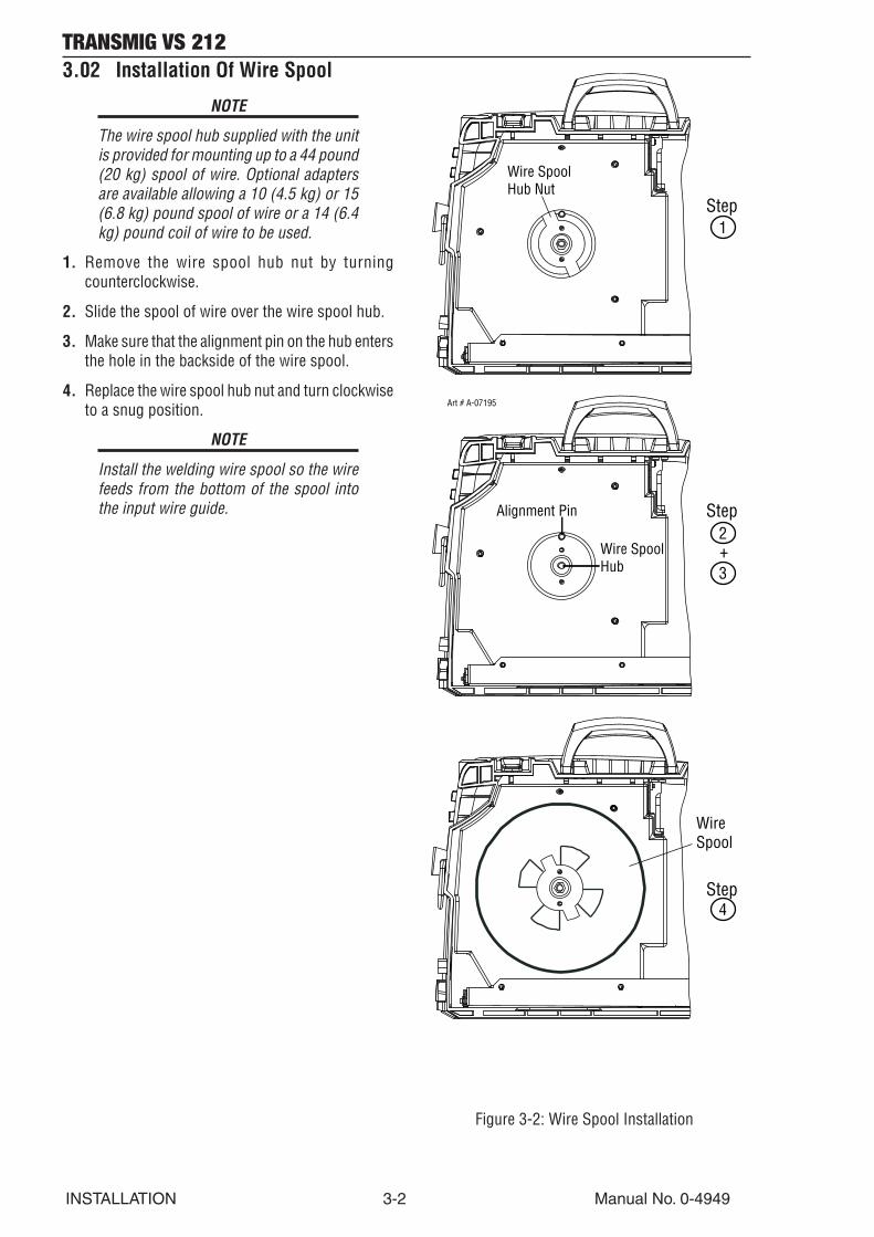
3.02 Installation Of Wire Spool
NOTE
The wire spool hub supplied with the unitis provided for mounting up to a 44 pound(20 kg) spool of wire. Optional adaptersare available allowing a 10 (4.5 kg) or 15(6.8 kg) pound spool of wire or a 14 (6.4kg) pound coil of wire to be used.
1. Remove the wire spool hub nut by turningcounterclockwise.
2. Slide the spool of wire over the wire spool hub.
3. Make sure that the alignment pin on the hub entersthe hole in the backside of the wire spool.
4. Replace the wire spool hub nut and turn clockwiseto a snug position.
NOTE
Install the welding wire spool so the wirefeeds from the bottom of the spool intothe input wire guide.
Wire SpoolHub Nut
Alignment Pin
Wire SpoolHub
Art # A-07195
1
2
3
4
WireSpool
Step
Step
Step
+
Figure 3-2: Wire Spool Installation
TRANSMIG VS 212
Manual No. 0-4949 3-3 INSTALLATION
NOTE
Before tightening the input and outputguide lockscrews, install the drive feed rollto help in the alignment of the wire guides.
Input WireGuide
Input GuideLockscrew
Output WireGuide (inside)
Output Guide Lockscrew
Art # A-07197
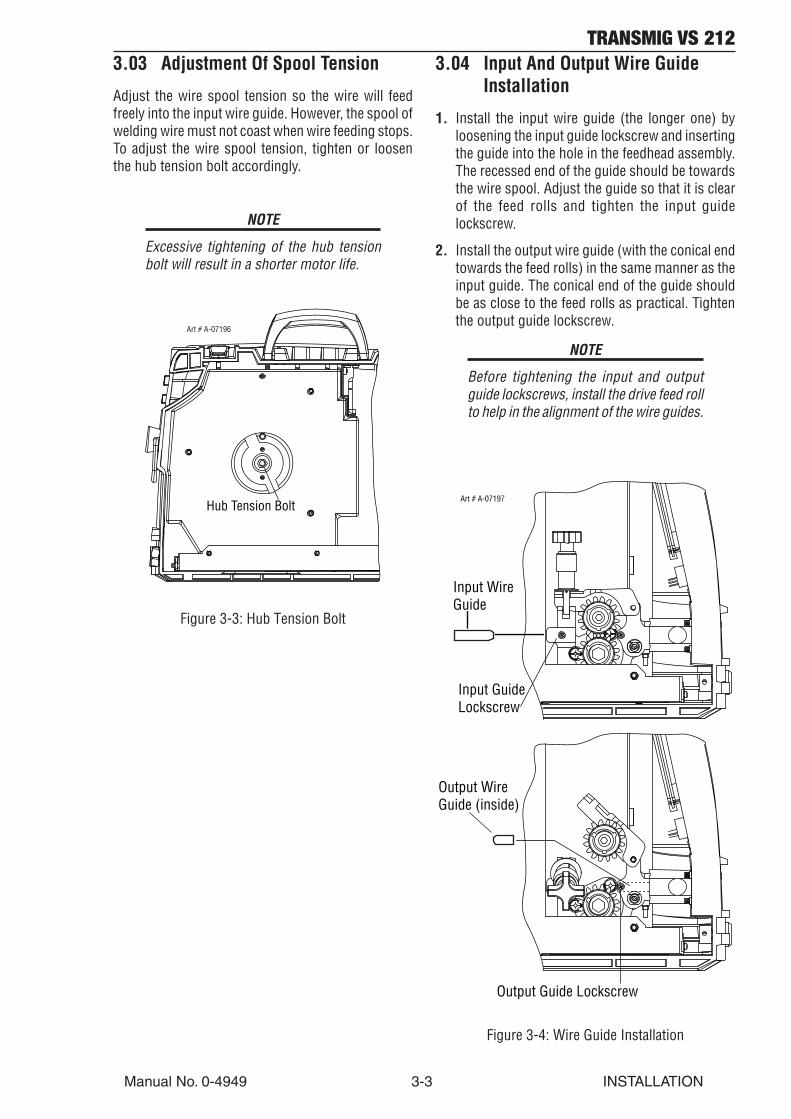
3.03 Adjustment Of Spool Tension
Adjust the wire spool tension so the wire will feedfreely into the input wire guide. However, the spool ofwelding wire must not coast when wire feeding stops.To adjust the wire spool tension, tighten or loosenthe hub tension bolt accordingly.
NOTE
Excessive tightening of the hub tensionbolt will result in a shorter motor life.
Hub Tension Bolt
Art # A-07196
Figure 3-3: Hub Tension Bolt
3.04 Input And Output Wire GuideInstallation
1. Install the input wire guide (the longer one) byloosening the input guide lockscrew and insertingthe guide into the hole in the feedhead assembly.The recessed end of the guide should be towardsthe wire spool. Adjust the guide so that it is clearof the feed rolls and tighten the input guidelockscrew.
2. Install the output wire guide (with the conical endtowards the feed rolls) in the same manner as theinput guide. The conical end of the guide shouldbe as close to the feed rolls as practical. Tightenthe output guide lockscrew.
Figure 3-4: Wire Guide Installation
TRANSMIG VS 212
INSTALLATION 3-4 Manual No. 0-4949
3.05 Selection And Installation OfFeed Rolls
Refer to feed roll kit chart in the Appendix chapter forthe proper selection and ordering of feed roll kits. Kitincludes a bearing roll, a drive roll, an input wire guide,and an output wire guide for a specific wire type andsize.
NOTE
All grooved feed rolls have their wire sizeor range stamped on the side of the roll.On rolls with different size grooves, theouter (visible when installed) stamped wiresize indicates the groove in use.
Bearing feed rolls are installed by unscrewing theupper retaining knob and removing the idler gear. Thebearing feed roll retaining knob is then removed fromthe idler gear, and the bearing feed roll is placed overthe lobes on the idler gear. The bearing feed rollretaining knob is replaced, and this assembly isreturned and secured with the upper retaining knob.
Drive feed rolls are installed by removing the lowerretaining knob, placing the drive feed roll over thelobes on the drive gear, and securing with the lowerretaining knob.
NOTE
Installation of all styles of feed rolls forthis feeder is identical.
! WARNING
The welding wire is electrically Hot if wireis fed by depressing gun switch. Electrodecontact to work piece will cause an arc withgun switch depressed.
3.06 MIG Gun Compatibility AndInstallation and Removal
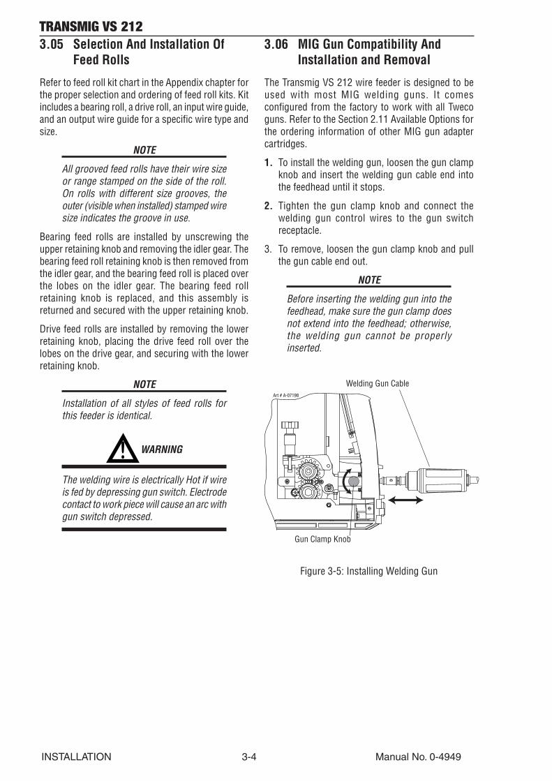
The Transmig VS 212 wire feeder is designed to beused with most MIG welding guns. It comesconfigured from the factory to work with all Twecoguns. Refer to the Section 2.11 Available Options forthe ordering information of other MIG gun adaptercartridges.
1. To install the welding gun, loosen the gun clampknob and insert the welding gun cable end intothe feedhead until it stops.
2. Tighten the gun clamp knob and connect thewelding gun control wires to the gun switchreceptacle.
3. To remove, loosen the gun clamp knob and pullthe gun cable end out.
NOTE
Before inserting the welding gun into thefeedhead, make sure the gun clamp doesnot extend into the feedhead; otherwise,the welding gun cannot be properlyinserted.
Art # A-07198
Gun Clamp Knob
Welding Gun Cable
Figure 3-5: Installing Welding Gun
TRANSMIG VS 212
Manual No. 0-4949 3-5 INSTALLATION
3.07 Threading Wire Into Feedhead
Refer to Figure 3-6.
! WARNING
ELECTRIC SHOCK CAN KILL! Make certainthe power source and wire feeder areturned OFF. Do not turn the power ON untiltold to do so in these instructions.
CAUTION
Use care when handling the spooled wire asthe wire tends to unravel when loosenedfrom the spool. Grasp the end of the wirefirmly, and don’t let it get away from you.Make sure that the end of the wire is straightand free of burrs.
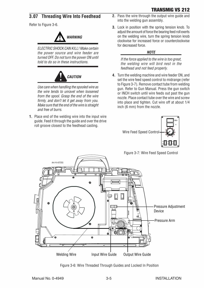
1. Place end of the welding wire into the input wireguide. Feed it through the guide and over the driveroll groove closest to the feedhead casting.
2. Pass the wire through the output wire guide andinto the welding gun assembly.
3. Lock in position with the spring tension knob. Toadjust the amount of force the bearing feed roll exertson the welding wire, turn the spring tension knobclockwise for increased force or counterclockwisefor decreased force.
NOTE
If the force applied to the wire is too great,the welding wire will bird nest in thefeedhead and not feed properly.
4. Turn the welding machine and wire feeder ON, andset the wire feed speed control to midrange (referto Figure 3-7). Remove contact tube from weldinggun. Refer to Gun Manual. Press the gun switchor INCH switch until wire feeds out past the gunnozzle. Place contact tube over the wire and screwinto place and tighten. Cut wire off at about 1/4inch (6 mm) from the nozzle.
Figure 3-6: Wire Threaded Through Guides and Locked In Position
Wire Feed Speed Control
Figure 3-7: Wire Feed Speed Control
Pressure AdjustmentDevice
Pressure Arm
Output Wire GuideInput Wire GuideWelding Wire
Art # A-07253

TRANSMIG VS 212
INSTALLATION 3-6 Manual No. 0-4949
NOTES
TRANSMIG VS 212
Manual No. 0-4949 4-1 OPERATION
SECTION 4:OPERATION
4.01 Prewelding Procedure
Follow all installation instructions for the weldingpower source, the welding gun, and the VS 212 CC/CV wire feeder before attempting to weld.
1. Make sure all necessary connections have beenmade (refer to Connections in the Installationchapter of this manual).
2. Turn ON the power source and the wire feeder.
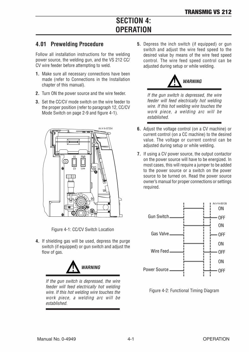
3. Set the CC/CV mode switch on the wire feeder tothe proper position (refer to paragraph 12, CC/CVMode Switch on page 2-9 and figure 4-1).
High
Low
CC
CV
Art # A-07254
Figure 4-1: CC/CV Switch Location
4. If shielding gas will be used, depress the purgeswitch (if equipped) or gun switch and adjust theflow of gas.
! WARNING
If the gun switch is depressed, the wirefeeder will feed electrically hot weldingwire. If this hot welding wire touches thework piece, a welding arc will beestablished.
5. Depress the inch switch (if equipped) or gunswitch and adjust the wire feed speed to thedesired value by means of the wire feed speedcontrol. The wire feed speed control can beadjusted during setup or while welding.
! WARNING
If the gun switch is depressed, the wirefeeder will feed electrically hot weldingwire. If this hot welding wire touches thework piece, a welding arc will beestablished.
6. Adjust the voltage control (on a CV machine) orcurrent control (on a CC machine) to the desiredvalue. The voltage or current control can beadjusted during setup or while welding.
7. If using a CV power source, the output contactoron the power source will have to be energized. Inmost cases, this will require a jumper to be addedto the power source or a switch on the powersource to be turned on. Read the power sourceowner’s manual for proper connections or settingsrequired.
Gun Switch
Gas Valve
Wire Feed
Power Source
ON
ON
ON
ON
OFF
OFF
OFF
OFF
Art # A-05126
Figure 4-2: Functional Timing Diagram

TRANSMIG VS 212
OPERATION 4-2 Manual No. 0-4949
4.02 Welding Procedure
! WARNING
In semiautomatic or automatic wirewelding, the welding wire, wire reel (ifused), input guide, feed rolls, output guide,feedhead, and welding gun metal parts areall ELECTRICALLY HOT.
Refer to Functional Timing Diagram on the previouspage.
1. To start the weld, position the welding gun abovethe work piece and depress the gun switch trigger.The solid state control then enables the gas valve,wire feed motor, and power source.
2. To end the weld, release the gun switch triggerwhile pulling the welding gun away from the workpiece. The solid state control then disables thegas valve, wire feed motor, and power source.
NOTE
After the weld is completed, it isrecommended to pull the welding gunaway from the work while releasing thegun switch. This allows the welding arc topartially extinguish at the work piece whichreduces the arcing at the contactorcontacts. Using this procedure willlengthen the life of the contactor contactsespecially when welding at high amperage.
3. At the end of the work day or when welding hasbeen completed, it is recommended that the gasbe SHUT OFF at the cylinder, and the wire feederand power source be turned OFF.
4.03 Welding In CC Mode vs. CVMode
1. Welding in CC Mode: When welding with aconstant current (CC) power source, changes inwire feed speed will affect welding voltage.
To adjust the amount of welding current from theCC power source, a control knob on the powersource or an optional control knob on the wirefeeder will have to be adjusted.
The solid state control of a “slow run-in” circuitautomatically reduces the initial wire feed speedwhen operating with a CC power source. This initialreduction in wire feed speed will compensate forthe high open circuit voltage associated with CCpower sources and improve arc startingperformance.
B. Welding in CV Mode: When welding with aconstant voltage (CV) power source, changes inwire feed speed will affect welding current.Changes in wire feed speed can be obtained byadjusting the wire feed speed control knob.
To adjust the amount of welding voltage from theCV power source, a control knob on the powersource or an optional control knob on the wirefeeder will have to be adjusted.
4.04 Theory Of Operation
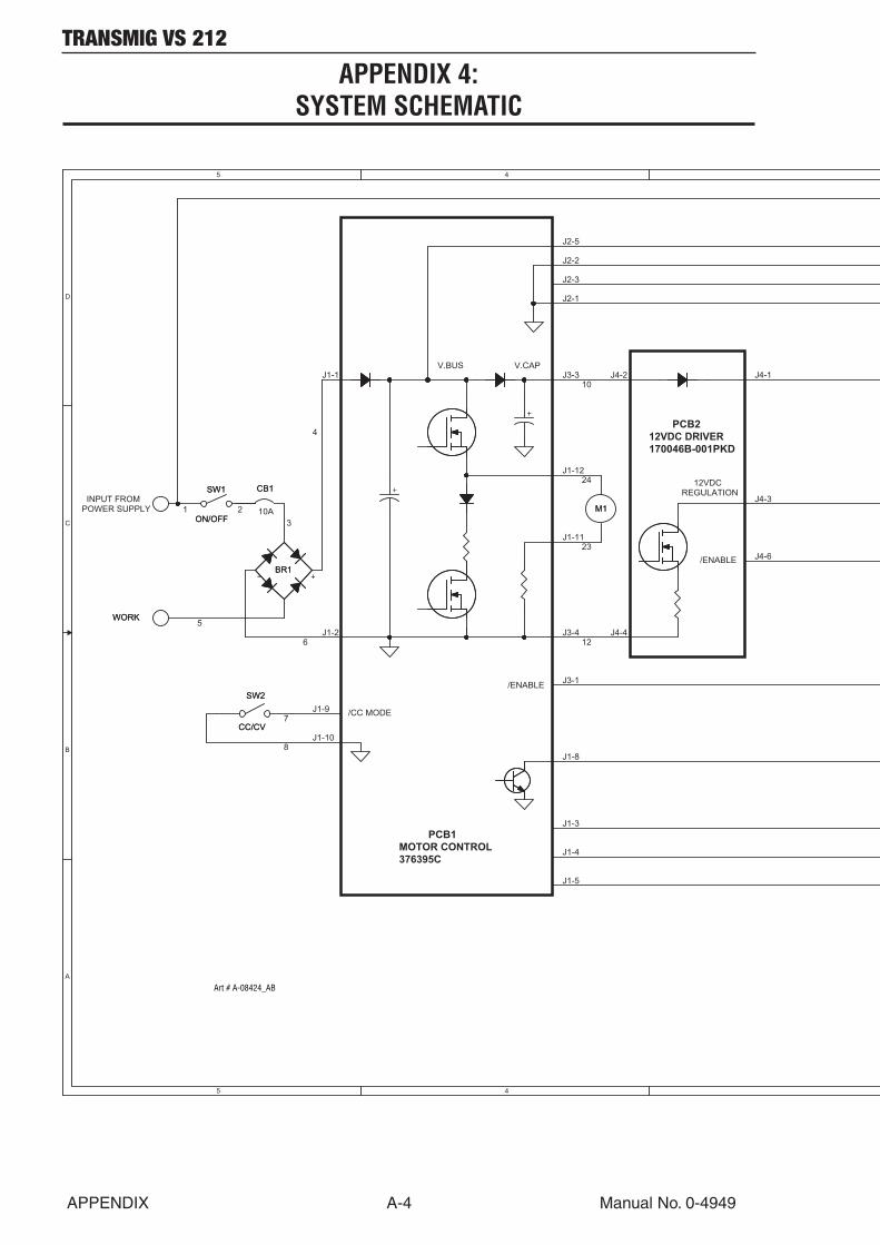
Refer to the Connection and Schematic Diagram inthe Appendix chapter of this manual.
Input power is supplied through the on/off switch (S1)and input circuit breaker (CB1) to the bridge rectifier(CR1). CR1 ensures that the proper polarity inputvoltage is fed into the PC boards independent of thewelding polarity.
When the gun switch on the welding gun is pulled, ashort is provided on the gun switch receptacle (J4)causing the wire feed motor (B1) to turn feeding wire,the gas valve (L1) to open allowing gas flow, and thecontactor (K1) to close making the welding wireelectrically hot.
When the gun switch on the welding gun is released,the short on the gun switch receptacle is removedcausing the wire feed motor to stop feeding wire, thegas valve to close stopping gas flow, and the contactorto open making the welding wire electrically cold.
TRANSMIG VS 212
Manual No. 0-4949 4-3 OPERATION
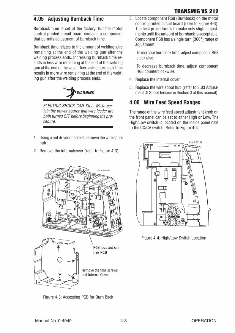
4.05 Adjusting Burnback Time
Burnback time is set at the factory, but the motorcontrol printed circuit board contains a componentthat permits adjustment of burnback time.
Burnback time relates to the amount of welding wireremaining at the end of the welding gun after thewelding process ends. Increasing burnback time re-sults in less wire remaining at the end of the weldinggun at the end of the weld. Decreasing burnback timeresults in more wire remaining at the end of the weld-ing gun after the welding process ends.
WARNING
ELECTRIC SHOCK CAN KILL. Make cer-tain the power source and wire feeder areboth turned OFF before beginning the pro-cedure.
1. Using a nut driver or socket, remove the wire spoolhub .
2. Remove the internalcover (refer to Figure 4-3).
Remove the four screwsand Internal Cover
Artr # A-09406
R68 located on this PCB
Figure 4-3: Accessing PCB for Burn Back
3. Locate component R68 (Burnback) on the motorcontrol printed circuit board (refer to Figure 4-3).The best procedure is to make only slight adjust-ments until the amount of burnback is acceptable.Component R68 has a single turn (360°) range ofadjustment.
To increase burnback time, adjust component R68clockwise.
To decrease burnback time, adjust componentR68 counterclockwise.
4. Replace the internal cover.
5. Replace the wire spool hub (refer to 3.03 Adjust-ment Of Spool Tension in Section 3 of this manual).
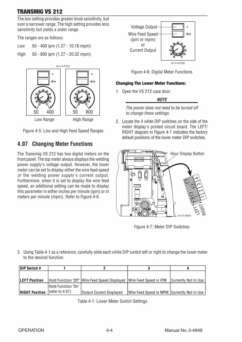
4.06 Wire Feed Speed Ranges
The range of the wire feed speed adjustment knob onthe front panel can be set to either High or Low. TheHigh/Low switch is located on the inside panel nextto the CC/CV switch. Refer to Figure 4-4.
High
Low
CC
CV
Art # A-07254
Figure 4-4: High/Low Switch Location
TRANSMIG VS 212
OPERATION 4-4 Manual No. 0-4949
The low setting provides greater knob sensitivity, butover a narrower range. The high setting provides lesssensitivity but yields a wider range.
The ranges are as follows:
Low 50 - 400 ipm (1.27 - 10.16 mpm)
High 50 - 800 ipm (1.27 - 20.32 mpm)
50 400 50 800
Art # A-07255
Low Range High Range
Figure 4-5: Low and High Feed Speed Ranges
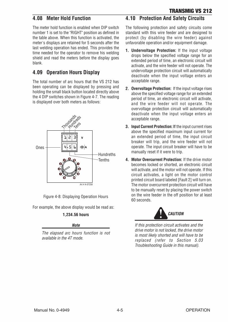
4.07 Changing Meter Functions
The Transmig VS 212 has two digital meters on thefront panel. The top meter always displays the weldingpower supply's voltage output. However, the lowermeter can be set to display either the wire feed speedor the welding power supply's current output.Furthermore, when it is set to display the wire feedspeed, an additional setting can be made to displaythis parameter in either inches per minute (ipm) or inmeters per minute (mpm). Refer to Figure 4-6.
Art # A-07256
Voltage Output
Wire Feed Speed(ipm or mpm)
orCurrent Output
Figure 4-6: Digital Meter Functions
Changing The Lower Meter Functions:
1. Open the VS 212 case door.
NOTE
The power does not need to be turned offto change these settings.
2. Locate the 4 white DIP switches on the side of themeter display's printed circuit board. The LEFT/RIGHT diagram in Figure 4-7 indicates the factorydefault positions of the lower meter DIP switches.
High
Low
CC
CV
Art # A-08353
Hour Display Button
12
34
LEFT
RIGH
T
Figure 4-7: Meter DIP Switches
3. Using Table 4-1 as a reference, carefully slide each white DIP switch left or right to change the lower meterto the desired function.
DIP Switch # 1 2 3 4
LEFT Position Hold Function "Off" Wire Feed Speed Displayed Wire Feed Speed in IPM Currently Not In Use
RIGHT PositionHold Function "On" (refer to 4.07) Output Current Displayed Wire Feed Speed in MPM Currently Not In Use
Table 4-1: Lower Meter Switch Settings
TRANSMIG VS 212
Manual No. 0-4949 4-5 OPERATION
4.08 Meter Hold Function
The meter hold function is enabled when DIP switchnumber 1 is set to the "RIGHT" position as defined inthe table above. When this function is activated, themeter's displays are retained for 5 seconds after thelast welding operation has ended. This provides thetime needed for the operator to remove his weldingshield and read the meters before the display goesblank.
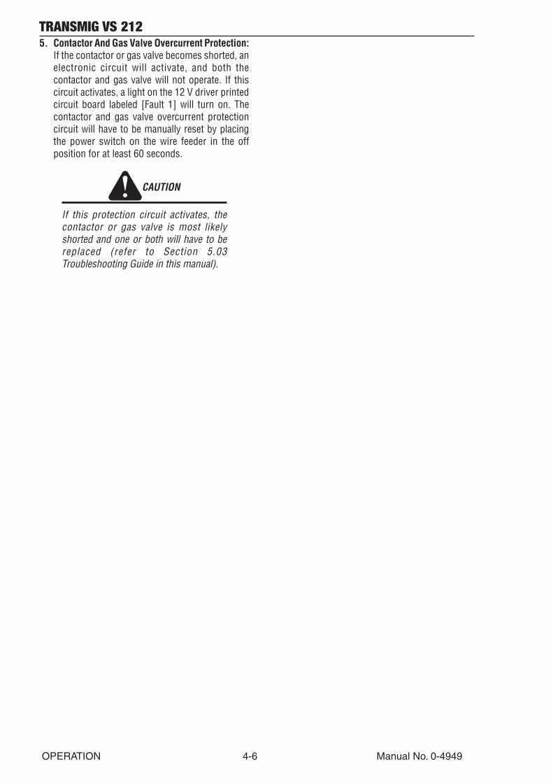
4.09 Operation Hours Display
The total number of arc hours that the VS 212 hasbeen operating can be displayed by pressing andholding the small black button located directly abovethe 4 DIP switches shown in Figure 4-7. The readingis displayed over both meters as follows:
Art # A-07258
Thou
sand
s
Hundre
ds
Tens
Ones
HundrethsTenths
1 2 3
4.5 6
Figure 4-8: Displaying Operation Hours
For example, the above display would be read as:
1,234.56 hours
Note
The elapsed arc hours function is notavailable in the 4T mode.
4.10 Protection And Safety Circuits
The following protection and safety circuits comestandard with this wire feeder and are designed toprotect (by disabling the wire feeder) againstunfavorable operation and/or equipment damage.
1. Undervoltage Protection: If the input voltagedrops below the specified voltage range for anextended period of time, an electronic circuit willactivate, and the wire feeder will not operate. Theundervoltage protection circuit will automaticallydeactivate when the input voltage enters anacceptable range.
2. Overvoltage Protection: If the input voltage risesabove the specified voltage range for an extendedperiod of time, an electronic circuit will activate,and the wire feeder will not operate. Theovervoltage protection circuit will automaticallydeactivate when the input voltage enters anacceptable range.
3. Input Current Protection: If the input current risesabove the specified maximum input current foran extended period of time, the input circuitbreaker will trip, and the wire feeder will notoperate. The input circuit breaker will have to bemanually reset if it were to trip.
4. Motor Overcurrent Protection: If the drive motorbecomes locked or shorted, an electronic circuitwill activate, and the motor will not operate. If thiscircuit activates, a light on the motor controlprinted circuit board labeled [Fault 2] will turn on.The motor overcurrent protection circuit will haveto be manually reset by placing the power switchon the wire feeder in the off position for at least60 seconds.
CAUTION
If this protection circuit activates and thedrive motor is not locked, the drive motoris most likely shorted and will have to bereplaced (refer to Section 5.03Troubleshooting Guide in this manual).
TRANSMIG VS 212
OPERATION 4-6 Manual No. 0-4949
5. Contactor And Gas Valve Overcurrent Protection:If the contactor or gas valve becomes shorted, anelectronic circuit will activate, and both thecontactor and gas valve will not operate. If thiscircuit activates, a light on the 12 V driver printedcircuit board labeled [Fault 1] will turn on. Thecontactor and gas valve overcurrent protectioncircuit will have to be manually reset by placingthe power switch on the wire feeder in the offposition for at least 60 seconds.
CAUTION
If this protection circuit activates, thecontactor or gas valve is most likelyshorted and one or both will have to bereplaced (refer to Section 5.03Troubleshooting Guide in this manual).
TRANSMIG VS 212
Manual No. 0-4949 5-1 SERVICE
SECTION 5: SERVICE
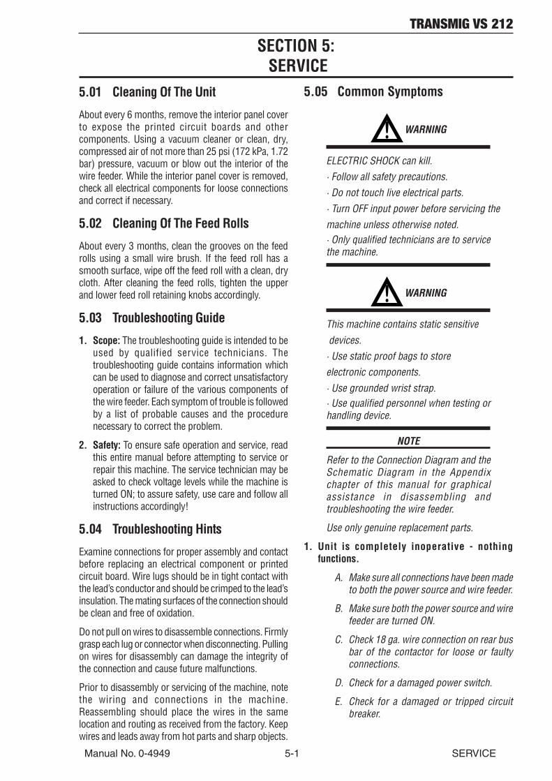
5.01 Cleaning Of The Unit
About every 6 months, remove the interior panel coverto expose the printed circuit boards and othercomponents. Using a vacuum cleaner or clean, dry,compressed air of not more than 25 psi (172 kPa, 1.72bar) pressure, vacuum or blow out the interior of thewire feeder. While the interior panel cover is removed,check all electrical components for loose connectionsand correct if necessary.
5.02 Cleaning Of The Feed Rolls
About every 3 months, clean the grooves on the feedrolls using a small wire brush. If the feed roll has asmooth surface, wipe off the feed roll with a clean, drycloth. After cleaning the feed rolls, tighten the upperand lower feed roll retaining knobs accordingly.
5.03 Troubleshooting Guide
1. Scope: The troubleshooting guide is intended to beused by qualified service technicians. Thetroubleshooting guide contains information whichcan be used to diagnose and correct unsatisfactoryoperation or failure of the various components ofthe wire feeder. Each symptom of trouble is followedby a list of probable causes and the procedurenecessary to correct the problem.
2. Safety: To ensure safe operation and service, readthis entire manual before attempting to service orrepair this machine. The service technician may beasked to check voltage levels while the machine isturned ON; to assure safety, use care and follow allinstructions accordingly!
5.04 Troubleshooting Hints
Examine connections for proper assembly and contactbefore replacing an electrical component or printedcircuit board. Wire lugs should be in tight contact withthe lead’s conductor and should be crimped to the lead’sinsulation. The mating surfaces of the connection shouldbe clean and free of oxidation.
Do not pull on wires to disassemble connections. Firmlygrasp each lug or connector when disconnecting. Pullingon wires for disassembly can damage the integrity ofthe connection and cause future malfunctions.
Prior to disassembly or servicing of the machine, notethe wiring and connections in the machine.Reassembling should place the wires in the samelocation and routing as received from the factory. Keepwires and leads away from hot parts and sharp objects.
5.05 Common Symptoms
! WARNING
ELECTRIC SHOCK can kill.· Follow all safety precautions.· Do not touch live electrical parts.· Turn OFF input power before servicing themachine unless otherwise noted.· Only qualified technicians are to servicethe machine.
! WARNING
This machine contains static sensitive devices.· Use static proof bags to storeelectronic components.· Use grounded wrist strap.· Use qualified personnel when testing orhandling device.
NOTE
Refer to the Connection Diagram and theSchematic Diagram in the Appendixchapter of this manual for graphicalassistance in disassembling andtroubleshooting the wire feeder.
Use only genuine replacement parts.
1. Unit is completely inoperative - nothingfunctions.
A. Make sure all connections have been madeto both the power source and wire feeder.
B. Make sure both the power source and wirefeeder are turned ON.
C. Check 18 ga. wire connection on rear busbar of the contactor for loose or faultyconnections.
D. Check for a damaged power switch.
E. Check for a damaged or tripped circuitbreaker.

TRANSMIG VS 212
SERVICE 5-2 Manual No. 0-4949
2. Wire feed motor operates but wire does not feedor feeds erratically.
A. Incorrect voltage/current and/or wire feedspeed settings.
1) Make sure all connections to the wirefeeder are tight.
2) Make sure feed rolls are tight.
B. Check for too little or too much pressureon the feed rolls.
1) Refer to spring tension knob in section2.09 Internal Controls and Connectionsin this manual.
2) Check for correct feed roll size forwelding wire being used.
3) Check to see if wire spool tension istoo great.
4) Refer to hub tension bolt in section2.09 Internal Controls and Connectionsin this manual.
C. Check for restriction in welding gun and/or contact tip.
D. Check for correct gun liner and contacttip sizes for welding wire being used.
3. Wire wraps around the feed rolls.
A. Check for too much pressure on the feedrolls.
1) Refer to spring tension knob in section2.09 Internal Controls AndConnections in this manual.
B. Check alignment of input and output guides.
C. Check for correct gun liner and contacttip sizes for welding wire being used.
D. Worn or damaged contact tip.
4. Wire does not feed with gun switch depressed.
A. Check power supply input to the VS 212and cable connection.
B. Check for continuity of the welding guntrigger leads with the trigger depressed.
1) If no continuity, repair or replace thewelding gun.
C. Check for a locked or shorted motor.
D. An electronic protection circuit may haveactivated.
1) Reset by placing power switch in theoff position for at least 60 seconds.
5. Wire feed motor continues to run after gun switchhas been released.
A. Check Trigger Hold switch (see section2.08).
B. Check for shorted welding gun triggerleads while the gun switch on the weldinggun is released.
1) If shorted, repair or replace the weldinggun.
6. Wire feeds but no gas flows.
A. Check to see if the gas cylinder is emptyor the valve closed.
1) Make sure proper gas flow rate hasbeen set.
B. Check for a possible restriction in the gasline or gas valve.
1) Check to see if the welding gun nozzleis plugged.
7. Gas flows all the time or leaks.
A. Make sure all connections are tight.
B. Check for foreign material inside the gasvalve.
8. Wire feeds, contactor closes, but welding wireis not hot - there is no arc.
A. Make sure all connections have been madeto both the power source and wire feeder.
B. Make sure the cable between the contactorand feedhead is properly connected.
1) If using a CV power source, make surethe output contactor has beenenergized.
2) Refer to section 4.01 PreweldingProcedure in this manual.
C. Work lead not connected.

TRANSMIG VS 212
SECTION 6:PARTS LIST
6.01 Equipment Identification
All identification numbers as described in theIntroduction chapter must be furnished when orderingparts or making inquiries. This information is usuallyfound on the nameplate attached to the equipment.Be sure to include any dash numbers following theSpecification or Assembly numbers.
6.02 How To Use This Parts List
The Parts List is a combination of an illustration and acorresponding list of parts which contains abreakdown of the equipment into assemblies,subassemblies, and detail parts. All parts of theequipment are listed except for commercially availablehardware, bulk items such as wire, cable, sleeving,tubing, etc., and permanently attached items whichare soldered, riveted, or welded to other parts. Thepart descriptions may be indented to show partrelationships.
To determine the part number, description, quantity,or application of an item, simply locate the item inquestion from the illustration and refer to that itemnumber in the corresponding Parts List.
PART NUMBERS:
W3512006

TRANSMIG VS 2126.03 External Replacement Parts
Item #Item #Item #Item #Item # QtyQtyQtyQtyQty DescriptionDescriptionDescriptionDescriptionDescription Part NumberPart NumberPart NumberPart NumberPart Number1 1 Control Knob 870696PKD2 2 Rocker Switch, Single Pole, Black 870359PKD3 1 Rocker Switch, Single Pole,Momentary, Black 870863PKD4 2 Door Latch Assembly, VS 212 871621PKD5 1 Assembly, Handle, VS 212 870972PKD6 1 Assembly, Door, VS 212 870953PKD7 1 Lifting Eye, VS 212 870974PKD8 1 Power Input Pigtail Assembly, VS 212 871316PKD9 1 Rocker Switch, Single Pole, Black. On/off 870359PKD
4
1
5
2
6
8
7
3
9
Art# A-07606
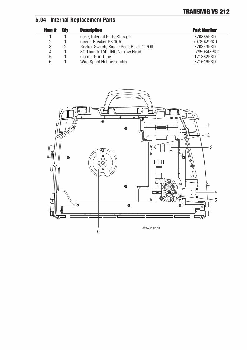
TRANSMIG VS 2126.04 Internal Replacement Parts
Item #Item #Item #Item #Item # QtyQtyQtyQtyQty DescriptionDescriptionDescriptionDescriptionDescription Part NumberPart NumberPart NumberPart NumberPart Number1 1 Case, Internal Parts Storage 870865PKD2 1 Circuit Breaker PB 10A 7978049PKD3 2 Rocker Switch, Single Pole, Black On/Off 870359PKD4 1 SC Thumb 1/4" UNC Narrow Head 7950348PKD5 1 Clamp, Gun Tube 171362PKD6 1 Wire Spool Hub Assembly 871616PKD
1
2
3
5
4
6Art #A-07607_AB

TRANSMIG VS 2126.05 Wire Feeder Replacement Parts
Item #Item #Item #Item #Item # QtyQtyQtyQtyQty DescriptionDescriptionDescriptionDescriptionDescription Part NumberPart NumberPart NumberPart NumberPart Number1 1 Tension Rod Subassembly 870933PKD2 1 Pressure Arm, Machined, Two Roll (see note 2) 870679PKD3 1 Idler Gear Assembly 871001PKD4 2 M4x10 Pan Head Screw See note 15 3 M6x1 Pan Head, 30 MM long See note 16 1 Gear Retainer 870733PKD7 1 Drive Gear Assembly 870560PKD8 2 M8 X 16 Hex Head Cap Screw See note 19 1 M6x1 Socket Head Cap Screw, 35MM Long See note 1
10 1 Clamp, Gun Tube (see note 2) 171362PKD11 1 Feedplate, 2 Roll, Machined (see note 2) 870558PKD12 1 Insulator, Motor (see note 2) 870695-001PKD13 1 Dowel Pin, #6x50, Pressure Arm hinge (see note 2) 870509PKD
1
2
3
4
56
78
9
10
11
12
13
Art # A-07608
NOTES:
1. This part may be purchased at a local hardware store.
TRANSMIG VS 212
Manual No. 0-4949 A-1 APPENDIX
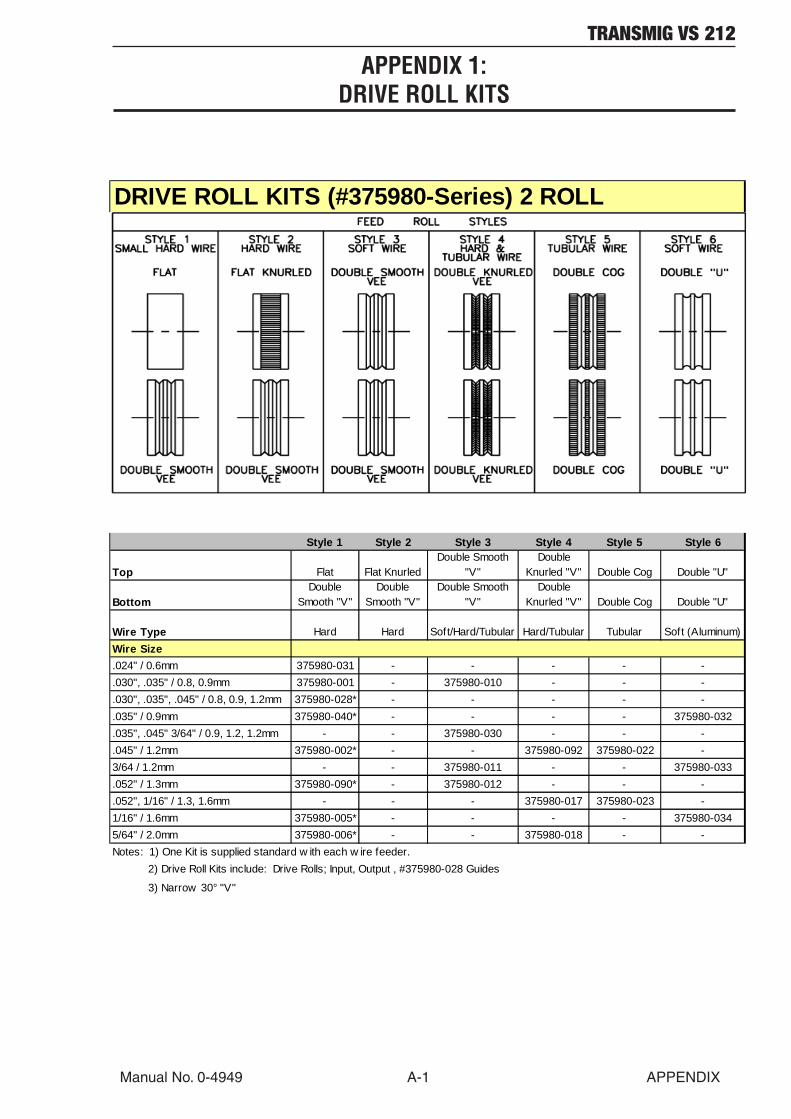
APPENDIX 1:DRIVE ROLL KITS
Style 1 Style 2 Style 3 Style 4 Style 5 Style 6
Top Flat Flat KnurledDouble Smooth
"V"Double
Knurled "V" Double Cog Double "U"
BottomDouble
Smooth "V"Double
Smooth "V"Double Smooth
"V"Double
Knurled "V" Double Cog Double "U"
Wire Type Hard Hard Soft/Hard/Tubular Hard/Tubular Tubular Soft (Aluminum)Wire Size.024" / 0.6mm 375980-031 - - - - -.030", .035" / 0.8, 0.9mm 375980-001 - 375980-010 - - -.030", .035", .045" / 0.8, 0.9, 1.2mm 375980-028* - - - - -.035" / 0.9mm 375980-040* - - - - 375980-032.035", .045" 3/64" / 0.9, 1.2, 1.2mm - - 375980-030 - - -.045" / 1.2mm 375980-002* - - 375980-092 375980-022 -3/64 / 1.2mm - - 375980-011 - - 375980-033.052" / 1.3mm 375980-090* - 375980-012 - - -.052", 1/16" / 1.3, 1.6mm - - - 375980-017 375980-023 -1/16" / 1.6mm 375980-005* - - - - 375980-0345/64" / 2.0mm 375980-006* - - 375980-018 - -Notes: 1) One Kit is supplied standard w ith each w ire feeder. 2) Drive Roll Kits include: Drive Rolls; Input, Output , #375980-028 Guides
3) Narrow 30° "V"
DRIVE ROLL KITS (#375980-Series) 2 ROLL
TRANSMIG VS 212
APPENDIX A-2 Manual No. 0-4949
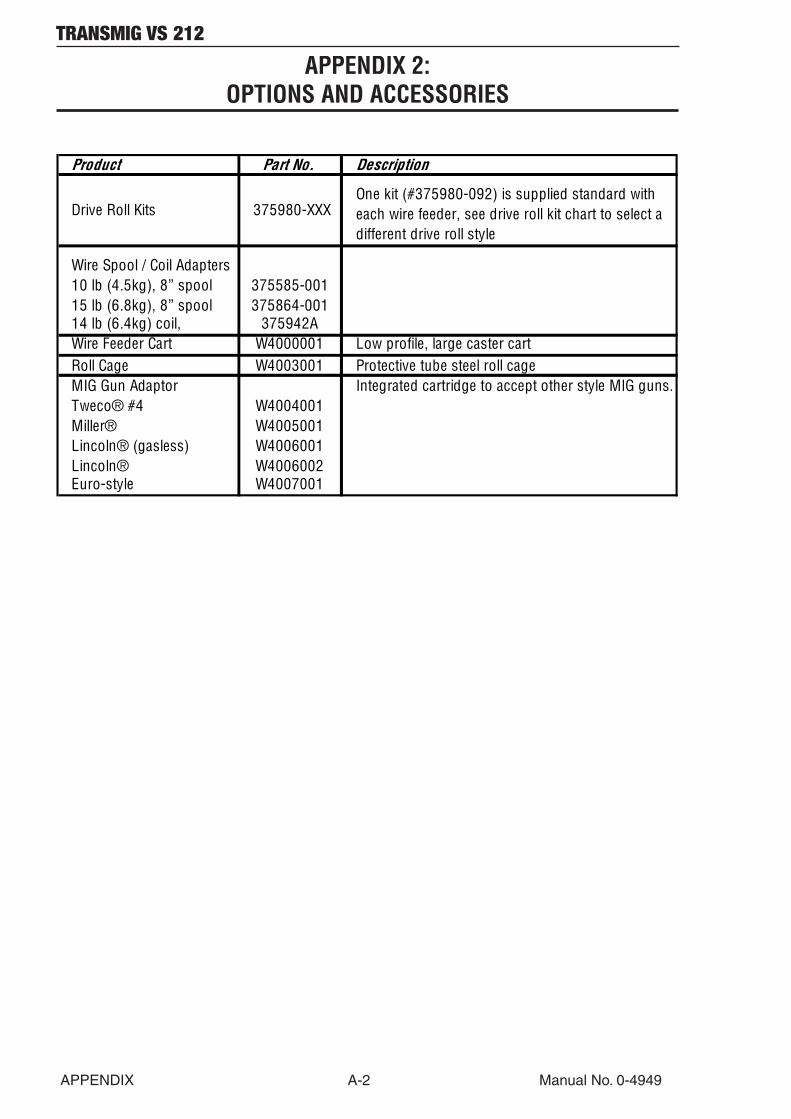
APPENDIX 2:OPTIONS AND ACCESSORIES
Product Part No. Description
Drive Roll Kits 375980-XXXOne kit (#375980-092) is supplied standard with each wire feeder, see drive roll kit chart to select a different drive roll style
Wire Spool / Coil Adapters 10 lb (4.5kg), 8” spool 375585-00115 lb (6.8kg), 8” spool 375864-00114 lb (6.4kg) coil, 375942AWire Feeder Cart W4000001 Low profile, large caster cart Roll Cage W4003001 Protective tube steel roll cage MIG Gun Adaptor Integrated cartridge to accept other style MIG guns.Tweco® #4 W4004001Miller® W4005001Lincoln® (gasless) W4006001Lincoln® W4006002Euro-style W4007001
TRANSMIG VS 212
Manual No. 0-4949 A-3 APPENDIX
APPENDIX 3:MIG GUN CARTRIDGE SYSTEM
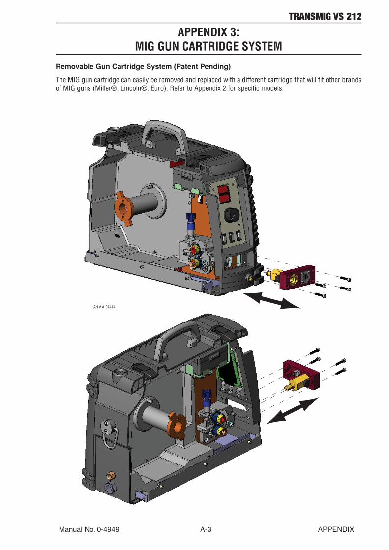
Removable Gun Cartridge System (Patent Pending)
The MIG gun cartridge can easily be removed and replaced with a different cartridge that will fit other brandsof MIG guns (Miller®, Lincoln®, Euro). Refer to Appendix 2 for specific models.
Art # A-07414
TRANSMIG VS 212
APPENDIX A-4 Manual No. 0-4949
APPENDIX 4:SYSTEM SCHEMATIC
5
5
4
4
D
C
B
A
INPUT FROM POWER SUPPLY 2
3
V.BUS V.CAP
J2-5
J2-2
J2-3
J2-1
J1-12
J1-11
J4-2J3-3
J3-4 J4-4
J4-6
J1-3
J1-4
J1-5
J1-1
J1-25
6
4
24
23
10
12
J1-9
J1-10
7
8
J4-3
J4-1
PCB1 MOTOR CONTROL376395C
PCB212VDC DRIVER 170046B-001PKD
/ENABLE J3-1
J1-8
/ENABLE
12VDC REGULATION
/CC MODE
1
WORKWORK
++
SW2
CC/CV
SW2
CC/CV
SW1
ON/OFF
SW1
ON/OFFM1M1
- +BR1- +BR1
++
CB1
10A
CB1
Art # A-08424_AB

TRANSMIG VS 212
Manual No. 0-4949 A-5 APPENDIX
3
3
2
2
1
1
D
C
B
A
+5VDC
+5VDC
DWG No:
Sheetof
SupersedesScale
Date:Drawn:
References
DateByRevisionsRev PCB No:Assy No:
Information Proprietary to CIGWELD CORPORATIONNot For Release, Reproduction, or Distribution without Written Consent.NOTE: UNLESS OTHERWISE SPECIFIED -
1. RESISTOR VALUES ARE EXPRESSED IN OHMS, 1/4W 5%.2. CAPACITOR VALUES ARE EXPRESSED IN MICROFARADS (uF). Chk: App:
TITLE:Last Modified:
SizeSCHEMATIC,
A THERMADYNE COMPANY
<RevCode>
Tuesday, March 04, 2008
1 1
Tuesday, February 26, 2008
09:09:46
DWG No:
Sheetof
SupersedesScale
Date:Drawn:
References
DateByRevisionsRev PCB No:Assy No:
Information Proprietary to Not For Release, Reproduction, or Distribution without Written Consent.NOTE: UNLESS OTHERWISE SPECIFIED -
1. RESISTOR VALUES ARE EXPRESSED IN OHMS, 1/4W 5%.2. CAPACITOR VALUES ARE EXPRESSED IN MICROFARADS (uF). Chk: App:
TITLE:Last Modified:
SizeSCHEMATIC,
A THERMADYNE COMPANY
<RevCode>
Tuesday, March 04, 2008
1 1
Tuesday, February 26, 2008
09:09:46
J7-11
J7-10
J7-9
J7-8
J7-4
J7-3
J7-12
J7-13
J7-14
J7-6
VOLTMETER (+)
VOLTMETER (-)
WFS METER (+)
WFS METER (-)
WFS POT MAX
WFS POT WIPER
WFS POT MIN
18
17
16
15
13
20
21
22
11 11A
9A
9
J7-2
J7-1
SELECTOR SW
J6-1
J6-2
J6-3/PURGE
J6-5
J5-3
J5-2
J5-1
CS1 CURRENT SENSE TRANSDUCER
DIGITAL DISPLAY
PCB3 PANEL PCB870949APKD
(ACTIVE LOW DURING PURGE & START)
/OVER-VOLTAGE FAULT
19
35
J7-7
J7-5
CONTACTOR CONTROL
J6-4
14
/INCH
STEALTH/HEFTY PRO
32
33
34
GUN SWITCH(/START / STOP)
FEEDHEAD
(MOUNTED ON W1 BUSS BAR)
10K
(W/METER 871014PKD)
30
34/HIGH
25
26
25
/4T MODE
SW5SW5
W1W1
TS1TS1
WFS POTWFS POT
SW3
LATCH MODE
SW3
LATCH MODE
J8J8
123456
1
23
4
* J9 PINOUT1
23
4
* J9 PINOUT
J8J8
123456
W1W1
SOL1SOL1
PTCPTC
SW6
HIGH/LOW SW
SW6
HIGH/LOW SW
J9*J9*
12
Art # A-08424_AB

Statement of Warranty
(as of March 15, 2009)
LIMITED WARRANTY:
THERMADYNE warrants that its products will be free of defects in workmanship or material. Should any failure toconform to this warranty appear within the time period applicable to the THERMADYNE products as stated below,THERMADYNE shall, upon written notification thereof and substantiation that the product has been stored, installed,operated, and maintained in accordance with THERMADYNE’s specifications, instructions, recommendations andrecognized standard industry practice, and not been subject to misuse, repair, neglect, alteration, or accident, correctsuch defects by suitable repair or replacement, at THERMADYNE’s sole option, of any components or parts of theproduct determined by THERMADYNE to be defective.
THIS WARRANTY IS EXCLUSIVE AND IS IN LIEU OF ALL OTHER WARRANTIES, EXPRESS OR IMPLIED, INCLUDINGANY WARRANTY OF MERCHANTABILITY OR FITNESS FOR A PARTICULAR PURPOSE.
LIMITATION OF LIABILITY:
THERMADYNE shall not under any circumstances be liable for special, indirect or consequentialdamages, such as, but not limited to, damage or loss of purchased or replacement goods, business interruption orloss of profit, or claims of customers of distributor (hereinafter the “Purchaser”) for service interruption. The rem-edies of the Purchaser set forth herein are exclusive and the liability of THERMADYNE with respect to any contract, oranything done in connection therewith such as the performance or breach thereof, or from the manufacture, sale,delivery, resale, or use of any goods covered by or furnished by THERMADYNE whether arising out of contract,negligence, strict tort, or under any warranty, or otherwise, shall not, except as expressly provided herein, exceed theprice of the goods upon which such liability is based.
THIS WARRANTY BECOMES INVALID IF REPLACEMENT PARTS OR ACCESSORIES ARE USED WHICH MAY IMPAIRTHE SAFETY OR PERFORMANCE OF ANY THERMADYNE PRODUCT.
THIS WARRANTY IS INVALID IF THE PRODUCT IS SOLD BY NON-AUTHORIZED PERSONS.
This warranty is effective for the time stated in the Warranty Schedule beginning on the date that the authorizeddistributor delivers the products to the Purchaser.
Warranty repairs or replacement claims under this limited warranty must be submitted by an authorized THERMADYNErepair facility within thirty (30) days of the repair. No transportation costs of any kind will be paid under this warranty.Transportation charges to send products to an authorized warranty repair facility shall be the responsibility of thePurchaser. All returned goods shall be at the Purchaser’s risk and expense. This warranty supersedes all previousTHERMADYNE warrantiesWarranty SCHEDULE

Warranty SCHEDULE
(as of March 15, 2009)
The warranty is effective below for the time stated in the Warranty Schedule beginning on the date that the authorizeddistributor delivers the products to the purchaser. THERMADYNE reserves the right to request documented evidenceof date of purchase.
ENGINE DRIVEN WELDERS Parts / LaborScout®, Raider®, Explorer™Original Main Power Stators and Inductors 5 years / 3 yearsOriginal Main Power Rectifiers, Control P.C. Boards 3 years / 3 yearsAll Other Original Circuits and Components Including, but not Limited to, Relays,Switches, Contactors, Solenoids, Fans, Power Switch Semi-Conductors 1 year / 1 yearEngines and Associated Components are NOT Warranted by Thermal Arc®, Although Most are Warranted by the Engine Manufacturer. SEE THE ENGINE MANUFACTURERS’ WARRANTY FOR DETAILS.
See the Engine Manufacturers’ Warranty
for DetailsGMAW/FCAW (MIG) WELDING EQUIPMENT Parts / LaborFabricator® 140, 180, 190, 210, 251, 281; Fabstar® 4030; PowerMaster® 350, 350P, 500, 500P, 320SP, 400SP, 500SP; Excel-Arc® 6045; Wire Feeders: Ultrafeed®, Porta-feed® Original Main Power Transformer and Inductor 5 years / 3 yearsOriginal Main Power Rectifiers, Control P.C. Boards, Power Switch Semi-Conductors 3 years / 3 yearsAll Other Original Circuits and Components Including, but not Limited to, Relays, Switches, Contactors, Solenoids, Fans, Electric Motors 1 year / 1 yearGTAW (TIG) & MULTI-PROCESS INVERTER WELDING EQUIPMENT Parts / Labor160TS, 300TS, 400TS, 185AC/DC, 200AC/DC, 300AC/DC, 400GTSW, 400MST, 300MST, 400MSTP Original Main Power Magnetics 5 years / 3 yearsOriginal Main Power Rectifiers, Control P.C. Boards, Power Switch Semi-Conductors 3 years / 3 yearsAll Other Original Circuits and Components Including, but not Limited to, Relays, Switches, Contactors, Solenoids, Fans, Electric Motors 1 year / 1 yearPLASMA WELDING EQUIPMENT Parts / LaborUltima® 150 Original Main Power Magnetics 5 years / 3 yearsOriginal Main Power Rectifiers, Control P.C. Boards, Power Switch Semi-Conductors 3 years / 3 yearsWelding Console, Weld Controller, Weld Timer 3 years / 3 yearsAll Other Original Circuits and Components Including, but not Limited to, Relays, Switches, Contactors, Solenoids, Fans, Electric Motors, Coolant Recirculators 1 year / 1 yearSMAW (Stick) WELDING EQUIPMENT Parts / LaborDragster™ 85; 95S Original Main Power Magnetics 1 year / 1 yearOriginal Main Power Rectifiers, Control P.C. Boards 1 year / 1 yearAll Other Original Circuits and Components Including, but not Limited to, Relays, Switches, Contactors, Solenoids, Fans, Power Switch Semi-Conductors 1 year / 1 year
Original Main Power Magnetics 5 years / 3 yearsOriginal Main Power Rectifiers, Control P.C. Boards 3 years / 3 yearsAll Other Original Circuits and Components Including, but not Limited to, Relays, Switches, Contactors, Solenoids, Fans, Power Switch Semi-Conductors 1 year / 1 yearGENERAL ARC EQUIPMENT Parts / LaborFirePower® MIG Welders 5-2-1 years / NAWater Recirculators 1 year / 1 yearPlasma Welding Torches 180 days / 180 daysGas Regulators (Supplied with Power Sources) 180 days / NAMIG and TIG Torches (Supplied with Power Sources) 90 days / NAReplacement Repair Parts 90 days / NAMIG, TIG and Plasma Welding Torch Consumable Items NA / NA


Thermadyne USA2800 Airport RoadDenton, Tx 76207 USATelephone: (940) 566-2000800-426-1888Fax: 800-535-0557Email: [email protected]
Thermadyne Canada2070 Wyecroft RoadOakville, OntarioCanada, L6L5V6Telephone: (905)-827-1111Fax: 905-827-3648
Thermadyne EuropeEurope BuildingChorley North Industrial ParkChorley, LancashireEngland, PR6 7BxTelephone: 44-1257-261755Fax: 44-1257-224800
Thermadyne, ChinaRM 102A685 Ding Xi RdChang Ning DistrictShanghai, PR, 200052Telephone: 86-21-69171135Fax: 86-21-69171139
Thermadyne Asia Sdn BhdLot 151, Jalan Industri 3/5ARawang Integrated Industrial Park - Jln Batu Arang48000 Rawang Selangor Darul EhsanWest MalaysiaTelephone: 603+ 6092 2988Fax : 603+ 6092 1085
Cigweld, Australia71 Gower StreetPreston, VictoriaAustralia, 3072Telephone: 61-3-9474-7400Fax: 61-3-9474-7510
Thermadyne ItalyOCIM, S.r.L.Via Bolsena, 720098 S. GiulianoMilan, ItalyTel: (39) 02-36546801Fax: (39) 02-36546840
Thermadyne International2070 Wyecroft RoadOakville, OntarioCanada, L6L5V6Telephone: (905)-827-9777Fax: 905-827-9797
GLOBAL CUSTOMER SERVICE CONTACT INFORMATION

World HeadquartersThermadyne Holdings CorporationSuite 300, 16052 Swingley Ridge RoadSt. Louis, MO 63017Telephone: (636) 728-3000FAX: (636) 728-3010Email: [email protected]