VR-201-L and VR-202-l IOM 11-30-09 fileARB Approved IOM - Executive Orders VR-201-L and VR-202-L...
20
ARB Approved IOM - Executive Orders VR-201-L and VR-202-L (Vapor Pressure Sensor Install Guide) Page 318 Manual No: 577013-797 ● Revision: Installation Guide Pressure Sensor L $5% $SSURYHG ,20 3UHVVXUH 6HQVRU ,QVWDOODWLRQ *XLGH ([HFXWLYH 2UGHU 95
Transcript of VR-201-L and VR-202-l IOM 11-30-09 fileARB Approved IOM - Executive Orders VR-201-L and VR-202-L...
ARB Approved IOM - Executive Orders VR-201-L and VR-202-L (Vapor Pressure Sensor Install Guide) Page 318
Manual No: 577013-797 ● Revision:
Installation Guide
Pressure Sensor
ARB Approved IOM - Executive Orders VR-201-L and VR-202-L (Vapor Pressure Sensor Install Guide) Page 319
Notice
Veeder-Root makes no warranty of any kind with regard to this publication, including, but not limited to, the implied warranties ofmerchantability and fitness for a particular purpose.
Veeder-Root shall not be liable for errors contained herein or for incidental or consequential damages in connection with thefurnishing, performance, or use of this publication.
Veeder-Root reserves the right to change system options or features, or the information contained in this publication.
This publication contains proprietary information which is protected by copyright. All rights reserved. No part of this publicationmay be modified or translated to another language without the prior written consent of Veeder-Root.
Contact TLS Systems Technical Support for additional troubleshooting information at 800-323-1799.
DAMAGE CLAIMS / LOST EQUIPMENT
Thoroughly examine all components and units as soon as they are received. If any cartons are damaged or missing, write acomplete and detailed description of the damage or shortage on the face of the freight bill. The carrier's agent must verify theinspection and sign the description. Refuse only the damaged product, not the entire shipment.
Veeder-Root must be notified of any damages and/or shortages within 30 days of receipt of the shipment, as stated in our Termsand Conditions.
VEEDER-ROOT’S PREFERRED CARRIER
1. Contact Veeder-Root Customer Service at 800-873-3313 with the specific part numbers and quantities that were missingor received damaged.
2. Fax signed Bill of Lading (BOL) to Veeder-Root Customer Service at 800-234-5350.
3. Veeder-Root will file the claim with the carrier and replace the damaged/missing product at no charge to the customer.Customer Service will work with production facility to have the replacement product shipped as soon as possible.
CUSTOMER’S PREFERRED CARRIER
1. It is the customer’s responsibility to file a claim with their carrier.
2. Customer may submit a replacement purchase order. Customer is responsible for all charges and freight associated withreplacement order. Customer Service will work with production facility to have the replacement product shipped as soon aspossible.
3. If “lost” equipment is delivered at a later date and is not needed, Veeder-Root will allow a Return to Stock without a restockingfee.
4. Veeder-Root will NOT be responsible for any compensation when a customer chooses their own carrier.
RETURN SHIPPING
For the parts return procedure, please follow the appropriate instructions in the "General Returned Goods Policy” pages in the"Policies and Literature" section of the Veeder-Root North American Environmental Products price list. Veeder-Root will notaccept any return product without a Return Goods Authorization (RGA) number clearly printed on the outside of the package.
©Veeder-Root 200 . All rights reserved.
ARB Approved IOM - Executive Orders VR-201-L and VR-202-L (Vapor Pressure Sensor Install Guide) Page 320
Table of Contents
ii
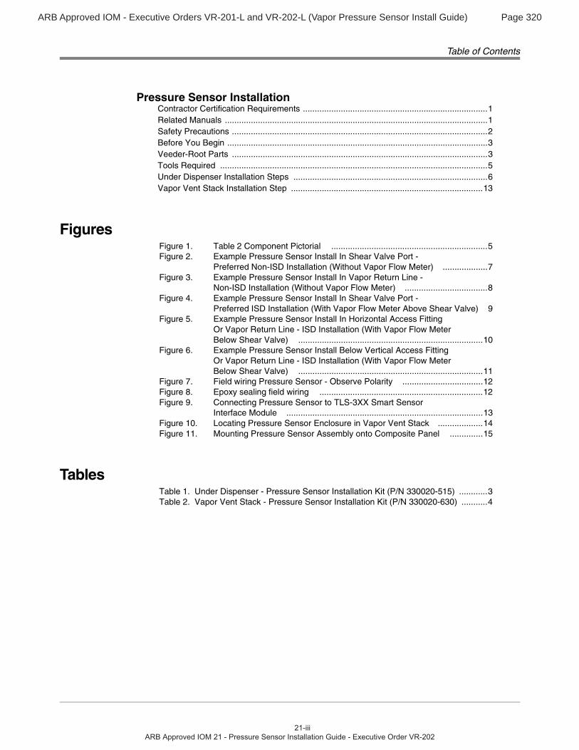
Pressure Sensor InstallationContractor Certification Requirements ..............................................................................1Related Manuals ...............................................................................................................1Safety Precautions ............................................................................................................2Before You Begin ..............................................................................................................3Veeder-Root Parts ............................................................................................................3Tools Required .................................................................................................................5Under Dispenser Installation Steps ..................................................................................6Vapor Vent Stack Installation Step .................................................................................13
FiguresFigure 1. Table 2 Component Pictorial ..................................................................5Figure 2. Example Pressure Sensor Install In Shear Valve Port -
Preferred Non-ISD Installation (Without Vapor Flow Meter) ...................7Figure 3. Example Pressure Sensor Install In Vapor Return Line -
Non-ISD Installation (Without Vapor Flow Meter) ...................................8Figure 4. Example Pressure Sensor Install In Shear Valve Port -
Preferred ISD Installation (With Vapor Flow Meter Above Shear Valve) 9Figure 5. Example Pressure Sensor Install In Horizontal Access Fitting
Or Vapor Return Line - ISD Installation (With Vapor Flow Meter Below Shear Valve) ..............................................................................10
Figure 6. Example Pressure Sensor Install Below Vertical Access Fitting Or Vapor Return Line - ISD Installation (With Vapor Flow Meter Below Shear Valve) ..............................................................................11
Figure 7. Field wiring Pressure Sensor - Observe Polarity ..................................12Figure 8. Epoxy sealing field wiring .....................................................................12Figure 9. Connecting Pressure Sensor to TLS-3XX Smart Sensor
Interface Module ...................................................................................13Figure 10. Locating Pressure Sensor Enclosure in Vapor Vent Stack ...................14Figure 11. Mounting Pressure Sensor Assembly onto Composite Panel ..............15
TablesTable 1. Under Dispenser - Pressure Sensor Installation Kit (P/N 330020-515) ............3Table 2. Vapor Vent Stack - Pressure Sensor Installation Kit (P/N 330020-630) ...........4
ARB Approved IOM - Executive Orders VR-201-L and VR-202-L (Vapor Pressure Sensor Install Guide) Page 321
Pressure Sensor Installation
This manual contains instructions to install a Veeder-Root (In-Station Diagnostic) Pressure Sensor in a dispenser’s vapor return line or in a vapor vent stack.
CAUTION: Installation of the pressure sensor on the vapor vent stack is only allowed at facilities equipped with a “Veeder-Root Vapor Polisher” or “Franklin Fueling System Healy Clean Air Separator.
This manual assumes all preliminary site preparation is completed, and that wiring from the console to the Pressure Sensor junction box is in place and meets the requirements set out in the console’s Site Prep manual.
Contractor Certification Requirements
Veeder-Root requires the following minimum training certifications for contractors who will install and setup the equipment discussed in this manual:
Installer (Level 1) Certification: Contractors holding valid Installer Certification are approved to perform wiring and conduit routing; equipment mounting; probe, sensor and carbon canister vapor polisher installation; tank and line preparation; and line leak detector installation.
TLS-350 Technician (Level 2/3 or 4) Certification: Contractors holding valid TLS-350 Technician Certifications are approved to perform installation checkout, startup, programming and operations training, troubleshooting and servicing for all Veeder-Root TLS-300 or TLS-350 Series Tank Monitoring Systems, including Line Leak Detection and associated accessories.
In-Station Diagnostics (ISD-PMC) Technician Certification: ISD PMC Contractors holding a valid ISD/PMC Certification are approved to perform (ISD/PMC) installation checkout, startup, programming, and operations training. This training also includes troubleshooting and service techniques for the Veeder-Root In-Station Diagnostics system. A current Veeder-Root Technician Certification is a prerequisite for the ISD/PMC course.
Veeder-Root ISD/PMC Including Carbon Canister Vapor Polisher Contractor Certification: This Certification includes Executive Orders 203, 204 and the Veeder-Root Vapor Polisher. This certification is required for setup and service of the Veeder-Root Vapor Polisher.
Warranty Registrations may only be submitted by selected Distributors.
Related Manuals
576013-879 TLS-3XX Series Consoles Site Prep and Installation Manual
577013-800 ISD Setup and Operation Manual
577013-801 PMC Setup and Operation Manual
577013-937 In-Station Diagnostics (ISD) Install, Setup, & Operation Manual
ARB Approved IOM - Executive Orders VR-201-L and VR-202-L (Vapor Pressure Sensor Install Guide) Page 322
Pressure Sensor Installation Safety Precautions
Safety Precautions
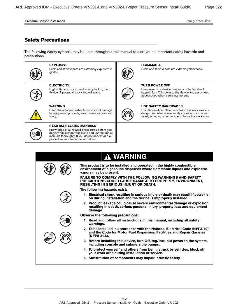
The following safety symbols may be used throughout this manual to alert you to important safety hazards and precautions.
EXPLOSIVEFuels and their vapors are extremely explosive if ignited.
FLAMMABLEFuels and their vapors are extremely flammable.
ELECTRICITYHigh voltage exists in, and is supplied to, the device. A potential shock hazard exists.
TURN POWER OFFLive power to a device creates a potential shock hazard. Turn Off power to the device and associated accessories when servicing the unit.
WARNINGHeed the adjacent instructions to avoid damage to equipment, property, environment or personal injury.
USE SAFETY BARRICADESUnauthorized people or vehicles in the work area are dangerous. Always use safety cones or barricades, safety tape, and your vehicle to block the work area.
READ ALL RELATED MANUALSKnowledge of all related procedures before you begin work is important. Read and understand all manuals thoroughly. If you do not understand a procedure, ask someone who does.
WARNINGThis product is to be installed and operated in the highly combustible environment of a gasoline dispenser where flammable liquids and explosive vapors may be present.FAILURE TO COMPLY WITH THE FOLLOWING WARNINGS AND SAFETY PRECAUTIONS COULD CAUSE DAMAGE TO PROPERTY, ENVIRONMENT, RESULTING IN SERIOUS INJURY OR DEATH.The following hazards exist:
1. Electrical shock resulting in serious injury or death may result if power is on during installation and the device is improperly installed.
2. Product leakage could cause severe environmental damage or explosion resulting in death, serious personal injury, property loss and equipment damage.
Observe the following precautions:1. Read and follow all instructions in this manual, including all safety
warnings.2. To be installed in accordance with the National Electrical Code (NFPA 70)
and the Code for Motor Fuel Dispensing Facilities and Repair Garages (NFPA 30A).
3. Before installing this device, turn Off, tag/lock out power to the system, including console and submersible pumps.
4. To protect yourself and others from being struck by vehicles, block off your work area during installation or service.
5. Substitution of components may impair intrinsic safety.
OFF
OFF
ARB Approved IOM - Executive Orders VR-201-L and VR-202-L (Vapor Pressure Sensor Install Guide) Page 323
Pressure Sensor Installation Before You Begin
3
Before You Begin
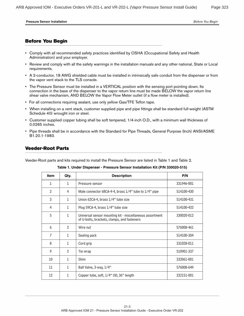
• Comply with all recommended safety practices identified by OSHA (Occupational Safety and Health Administration) and your employer.
• Review and comply with all the safety warnings in the installation manuals and any other national, State or Local requirements.
• A 2-conductor, 18 AWG shielded cable must be installed in intrinsically safe conduit from the dispenser or from the vapor vent stack to the TLS console.
• The Pressure Sensor must be installed in a VERTICAL position with the sensing port pointing down. Its connection in the base of the dispenser to the vapor return line must be made BELOW the vapor return line shear valve mechanism, AND BELOW the Vapor Flow Meter outlet (if a flow meter is installed).
• For all connections requiring sealant, use only yellow Gas/TFE Teflon tape.
• When installing on a vent stack, customer supplied pipe and pipe fittings shall be standard full-weight (ASTM Schedule 40) wrought iron or steel.
• Customer supplied copper tubing shall be soft tempered, 1/4-inch O.D., with a minimum wall thickness of 0.0265 inches.
• Pipe threads shall be in accordance with the Standard for Pipe Threads, General Purpose (Inch) ANSI/ASME B1.20.1-1983.
Veeder-Root Parts
Veeder-Root parts and kits required to install the Pressure Sensor are listed in Table 1 and Table 2.
Table 1. Under Dispenser - Pressure Sensor Installation Kit (P/N 330020-515)
Item Qty. Description P/N
1 1 Pressure sensor 331946-001
2 4 Male connector 68CA-4-4, brass 1/4” tube to 1/4” pipe 514100-430
3 1 Union 62CA-4, brass 1/4” tube size 514100-431
4 1 Plug 59CA-4, brass 1/4” tube size 514100-432
5 1 Universal sensor mounting kit - miscellaneous assortment of U-bolts, brackets, clamps, and fasteners
330020-012
6 2 Wire nut 576008-461
7 1 Sealing pack 514100-304
8 1 Cord grip 331028-011
9 2 Tie wrap 510901-337
10 1 Shim 332061-001
11 1 Ball Valve, 3-way, 1/4” 576008-649
12 1 Copper tube, soft, 1/4” OD, 36” length 332151-001
ARB Approved IOM - Executive Orders VR-201-L and VR-202-L (Vapor Pressure Sensor Install Guide) Page 324
Pressure Sensor Installation Veeder-Root Parts
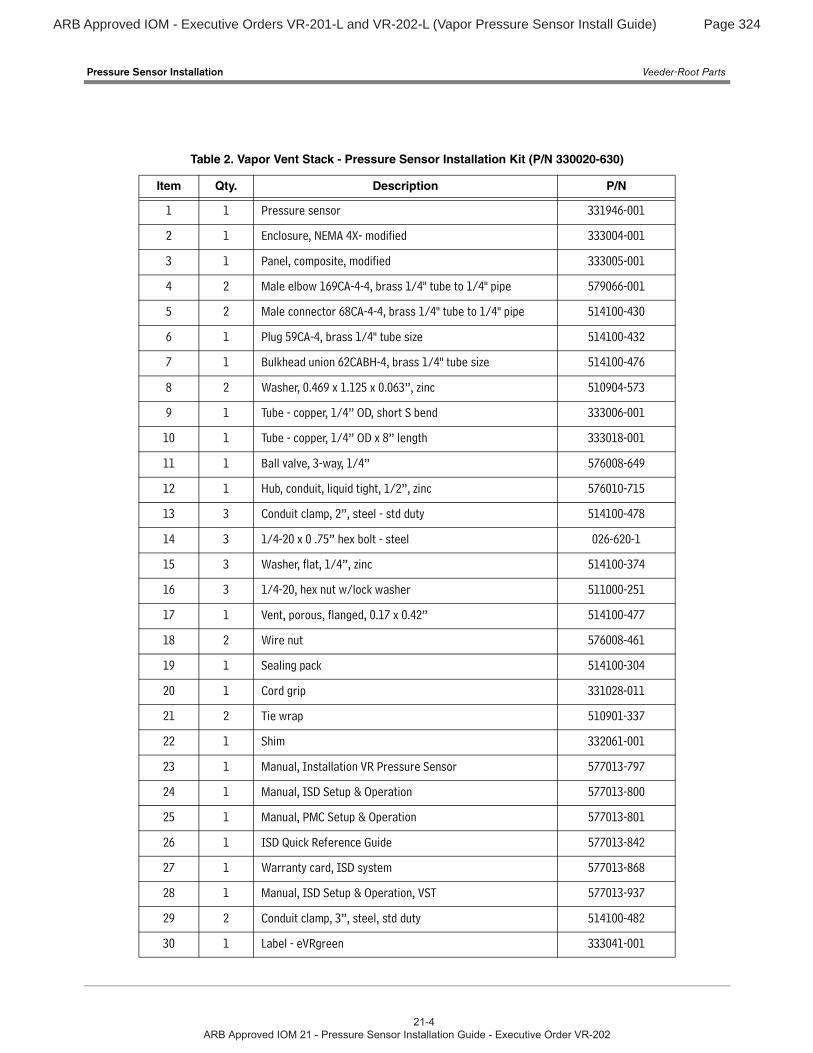
Table 2. Vapor Vent Stack - Pressure Sensor Installation Kit (P/N 330020-630)
Item Qty. Description P/N
1 1 Pressure sensor 331946-001
2 1 Enclosure, NEMA 4X- modified 333004-001
3 1 Panel, composite, modified 333005-001
4 2 Male elbow 169CA-4-4, brass 1/4" tube to 1/4" pipe 579066-001
5 2 Male connector 68CA-4-4, brass 1/4" tube to 1/4" pipe 514100-430
6 1 Plug 59CA-4, brass 1/4" tube size 514100-432
7 1 Bulkhead union 62CABH-4, brass 1/4" tube size 514100-476
8 2 Washer, 0.469 x 1.125 x 0.063”, zinc 510904-573
9 1 Tube - copper, 1/4” OD, short S bend 333006-001
10 1 Tube - copper, 1/4” OD x 8” length 333018-001
11 1 Ball valve, 3-way, 1/4” 576008-649
12 1 Hub, conduit, liquid tight, 1/2”, zinc 576010-715
13 3 Conduit clamp, 2”, steel - std duty 514100-478
14 3 1/4-20 x 0 .75” hex bolt - steel 026-620-1
15 3 Washer, flat, 1/4”, zinc 514100-374
16 3 1/4-20, hex nut w/lock washer 511000-251
17 1 Vent, porous, flanged, 0.17 x 0.42” 514100-477
18 2 Wire nut 576008-461
19 1 Sealing pack 514100-304
20 1 Cord grip 331028-011
21 2 Tie wrap 510901-337
22 1 Shim 332061-001
23 1 Manual, Installation VR Pressure Sensor 577013-797
24 1 Manual, ISD Setup & Operation 577013-800
25 1 Manual, PMC Setup & Operation 577013-801
26 1 ISD Quick Reference Guide 577013-842
27 1 Warranty card, ISD system 577013-868
28 1 Manual, ISD Setup & Operation, VST 577013-937
29 2 Conduit clamp, 3”, steel, std duty 514100-482
30 1 Label - eVRgreen 333041-001
ARB Approved IOM - Executive Orders VR-201-L and VR-202-L (Vapor Pressure Sensor Install Guide) Page 325
Pressure Sensor Installation Tools Required
5
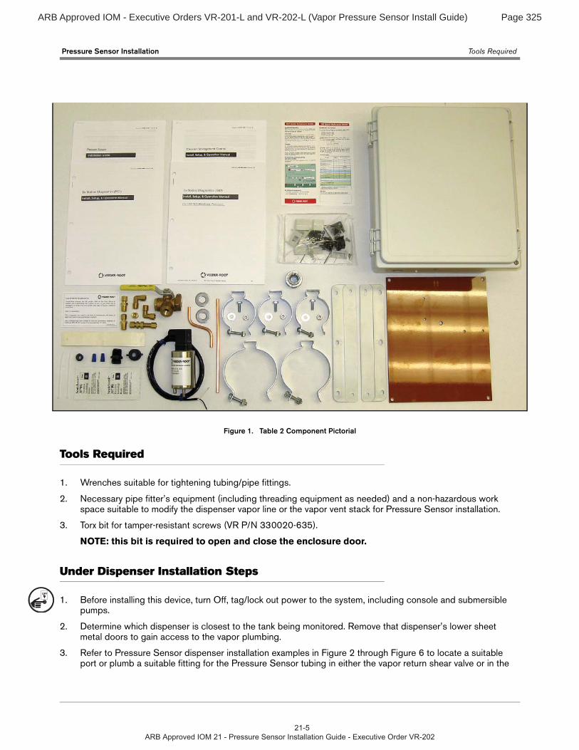
Figure 1. Table 2 Component Pictorial
Tools Required
1. Wrenches suitable for tightening tubing/pipe fittings.
2. Necessary pipe fitter’s equipment (including threading equipment as needed) and a non-hazardous work space suitable to modify the dispenser vapor line or the vapor vent stack for Pressure Sensor installation.
3. Torx bit for tamper-resistant screws (VR P/N 330020-635).
NOTE: this bit is required to open and close the enclosure door.
Under Dispenser Installation Steps
1. Before installing this device, turn Off, tag/lock out power to the system, including console and submersible pumps.
2. Determine which dispenser is closest to the tank being monitored. Remove that dispenser’s lower sheet metal doors to gain access to the vapor plumbing.
3. Refer to Pressure Sensor dispenser installation examples in Figure 2 through Figure 6 to locate a suitable port or plumb a suitable fitting for the Pressure Sensor tubing in either the vapor return shear valve or in the
OFF
ARB Approved IOM - Executive Orders VR-201-L and VR-202-L (Vapor Pressure Sensor Install Guide) Page 326
Pressure Sensor Installation Under Dispenser Installation Steps
vapor return line. NOTE: In ISD installations, the pressure port used must be below the vapor flow meter outlet.
4. Install one of the 68CA-4-4 male connectors (item 2 in Table 1) from the kit into the tapped hole.
5. Install Pressure Sensor (item 1 in Table 1) vertically to the dispenser frame or piping using the 2-inch conduit clamp, rubber shim, and necessary bolts, nuts, and washers from the included Universal Sensor Mounting kit. Wrap the rubber shim (item 10 in Table 1) around the sensor before inserting it into the clamp. Also make sure the sensor cable outlet is facing up and the pressure sensing port tube in the base of the sensor is facing down.
6. Attach one end of the 62CA-4 union (item 3 in Table 1) to the pressure sensing port in the base of the Pressure Sensor.
7. Install the remaining 68CA-4-4 male connectors (item 2 in Table 1) from the kit into each of the three ports in the 3-way calibration valve (item 13 in Table 1).
8. Measure, fabricate, and install a ¼" OD copper tube (item 12 in Table 1) that runs between the 62CA-4 union in the base of the sensor and the center port of the 3-way calibration valve.
9. Measure, fabricate, and install a ¼" OD copper tube that runs between the ¼" tube end of the male connector fitting installed beneath the shear valve mechanism and the right port on the 3-way valve, being careful not to create any potential liquid traps (Note 3-way valve orientation in Figure 6).
10. Screw the 59CA-4 plug, item 4, from the kit onto the left port’s male connector. Make sure the valve’s handle is set to connect the sensor to the vapor return line and not to the capped (ambient) port.
Important! All plumbing’s pitch to drain should be 1/4” vertical per 12” horizontal to eliminate liquid traps.
11. Route the cable from Pressure Sensor to the Pressure Sensor junction box in the dispenser. Observing polarity, connect the sensor wiring to the field wiring from console and cap with wire nuts (see Figure 7).
12. Seal wire nuts in epoxy sealant following the instructions in Figure 8.
13. Push the epoxy sealed bag into the junction box. Replace and tighten the junction box cover.
14. Terminate field wiring into TLS Console and connect to Smart Sensor Module (TLS-3XX - Figure 9). Note: observe polarity! The cable length between the console and sensor must not exceed the distance stated in the TLS-3XX Site Prep manual (P/N 576013-879).
Note: Intrinsically safe devices must be installed in accordance with Article 504 of the National Electrical Code, ANSI/NFPA 70, for installation in the United States, or Section 18 of the Canadian Electrical Code for installations in Canada.
This intrinsically safe Pressure Sensor P/N 331946-001, has only been evaluated for connection to a UL list-ed TLS-3XX Liquid Level Gauge / Leak Detector.
Conductors of different intrinsically safe circuits run in the same cable/conduit must have at least 0.01 inch (0.25 mm) of insulation.
15. After the Pressure Sensor is installed, pressurize the tank ullage space and vapor piping to at least 2 inches WC and test for leaks using leak detection solution.
16. Replace lower dispenser sheet metal doors onto dispensers.
ARB Approved IOM - Executive Orders VR-201-L and VR-202-L (Vapor Pressure Sensor Install Guide) Page 327
Pressure Sensor Installation Under Dispenser Installation Steps
7
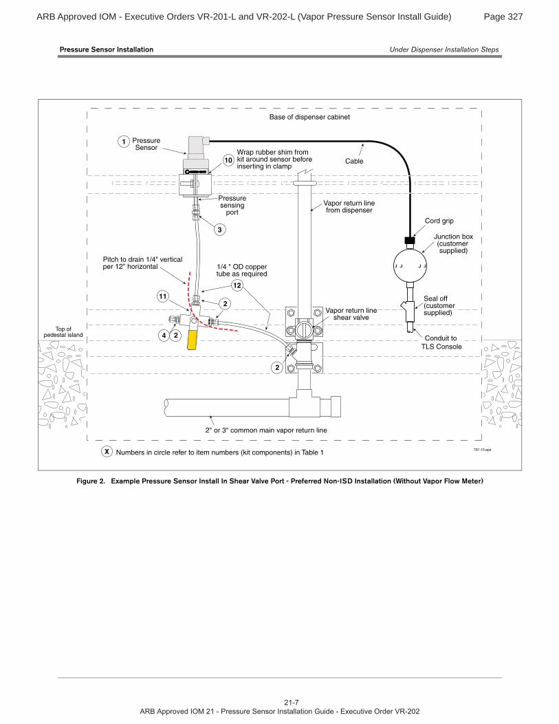
Figure 2. Example Pressure Sensor Install In Shear Valve Port - Preferred Non-ISD Installation (Without Vapor Flow Meter)
1/4 " OD coppertube as required
Conduit to TLS Console
Seal off(customersupplied)
Junction box(customer supplied)
Vapor return linefrom dispenser
2" or 3" common main vapor return line
PressureSensor
Wrap rubber shim from kit around sensor before inserting in clamp
Pressuresensing
port
Cable
Vapor return lineshear valve
Cord grip
Base of dispenser cabinet
797-10.eps
Pitch to drain 1/4" verticalper 12" horizontal
12
4
112
2
2
2
3
1
10
X Numbers in circle refer to item numbers (kit components) in Table 1
Top ofpedestal island
ARB Approved IOM - Executive Orders VR-201-L and VR-202-L (Vapor Pressure Sensor Install Guide) Page 328
Pressure Sensor Installation Under Dispenser Installation Steps
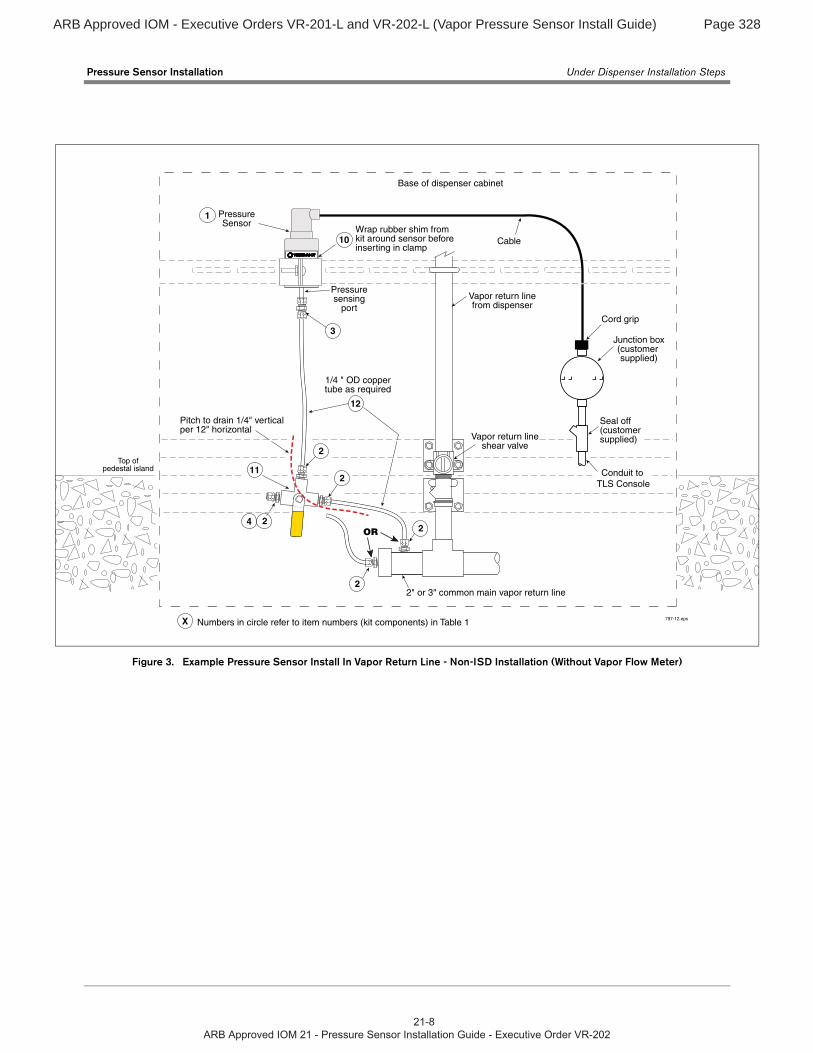
Figure 3. Example Pressure Sensor Install In Vapor Return Line - Non-ISD Installation (Without Vapor Flow Meter)
1/4 " OD coppertube as required
Conduit to TLS Console
Seal off(customersupplied)
Junction box(customer supplied)
Vapor return linefrom dispenser
2" or 3" common main vapor return line
PressureSensor
Wrap rubber shim from kit around sensor before inserting in clamp
Pressuresensing
port
Cable
Vapor return lineshear valve
Cord grip
Base of dispenser cabinet
797-12.eps
Pitch to drain 1/4" verticalper 12" horizontal
12
4
112
22
2
2
3
1
10
X Numbers in circle refer to item numbers (kit components) in Table 1
OR
Top ofpedestal island
ARB Approved IOM - Executive Orders VR-201-L and VR-202-L (Vapor Pressure Sensor Install Guide) Page 329
Pressure Sensor Installation Under Dispenser Installation Steps
9
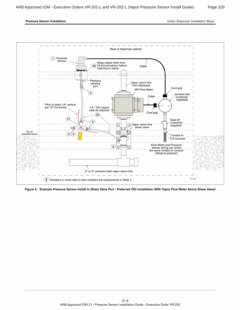
Figure 4. Example Pressure Sensor Install In Shear Valve Port - Preferred ISD Installation (With Vapor Flow Meter Above Shear Valve)
1/4 " OD coppertube as required
Conduit to TLS Console
Seal off(customersupplied)
Junction box(customer supplied)
Vapor return linefrom dispenser
2" or 3" common main vapor return line
PressureSensor
Wrap rubber shim from kit around sensor before inserting in clamp
Pressuresensing
port
Cable
Vapor return lineshear valve
Cord grip
Base of dispenser cabinet
797-9.eps
Pitch to drain 1/4" verticalper 12" horizontal
12
4
112
2
2
2
3
1
10
X Numbers in circle refer to item numbers (kit components) in Table 1
Top ofpedestal island
ISD Flow Meter
Cable
Cord grip
Flow Meter and PressureSensor wiring can share
the same conduit to console(Observe polarity!)
ARB Approved IOM - Executive Orders VR-201-L and VR-202-L (Vapor Pressure Sensor Install Guide) Page 330
Pressure Sensor Installation Under Dispenser Installation Steps
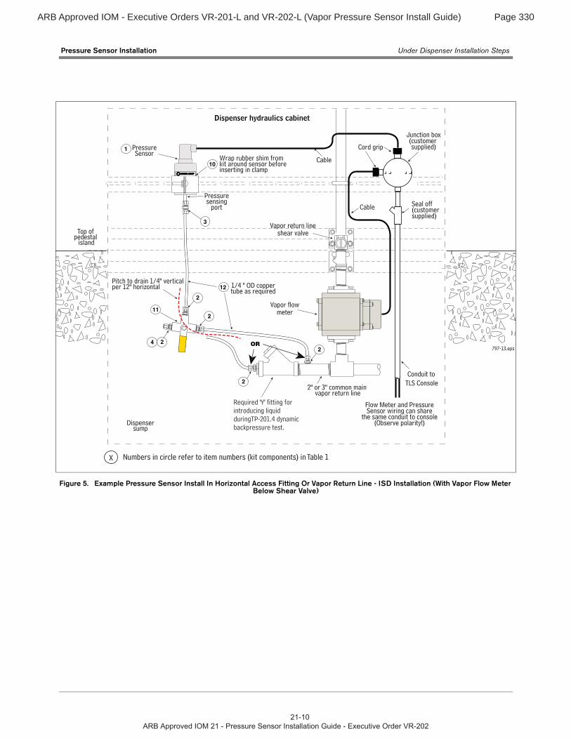
Figure 5. Example Pressure Sensor Install In Horizontal Access Fitting Or Vapor Return Line - ISD Installation (With Vapor Flow Meter Below Shear Valve)
Dispenser hydraulics cabinet
Top of pedestal
island
797-13.eps
Dispensersump
1/4 " OD coppertube as required
2" or 3" common main vapor return line
PressureSensor
Wrap rubber shim from kit around sensor before inserting in clamp
Pressuresensing
port
Pitch to drain 1/4" verticalper 12" horizontal 12
4
11
22
2
2
3
2
1
10
OR
Seal off(customersupplied)
Junction box(customer supplied)
Conduit to TLS Console
Cable
Cord grip
Flow Meter and PressureSensor wiring can share
the same conduit to console(Observe polarity!)
Required 'Y' fitting for introducing liquid duringTP-201.4 dynamic backpressure test.
Cable
Vapor return lineshear valve
Vapor flowmeter
X Numbers in circle refer to item numbers (kit components) in Table 1
ARB Approved IOM - Executive Orders VR-201-L and VR-202-L (Vapor Pressure Sensor Install Guide) Page 331
Pressure Sensor Installation Under Dispenser Installation Steps
11
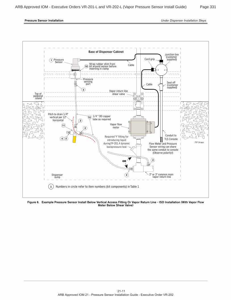
Figure 6. Example Pressure Sensor Install Below Vertical Access Fitting Or Vapor Return Line - ISD Installation (With Vapor Flow Meter Below Shear Valve)
Base of Dispenser Cabinet
797-14.eps
Dispensersump
2" or 3" common main vapor return line
PressureSensor
Wrap rubber shim from kit around sensor before inserting in clamp
Pressuresensing
port
3
1
10
Seal off(customersupplied)
Junction box(customer supplied)
Conduit to TLS Console
Cable
Cable
Cord grip
Flow Meter and PressureSensor wiring can share
the same conduit to console(Observe polarity!)
Required 'Y' fitting for introducing liquid
duringTP-201.4 dynamic backpressure test
1/4 " OD coppertube as required
12
4
11
2
2
2
Pitch to drain 1/4" vertical per 12"
horizontal
Top of pedestal
island
Vapor return lineshear valve
Vapor flowmeter
2
X Numbers in circle refer to item numbers (kit components) in Table 1
2OR
ARB Approved IOM - Executive Orders VR-201-L and VR-202-L (Vapor Pressure Sensor Install Guide) Page 332
Pressure Sensor Installation Under Dispenser Installation Steps
.
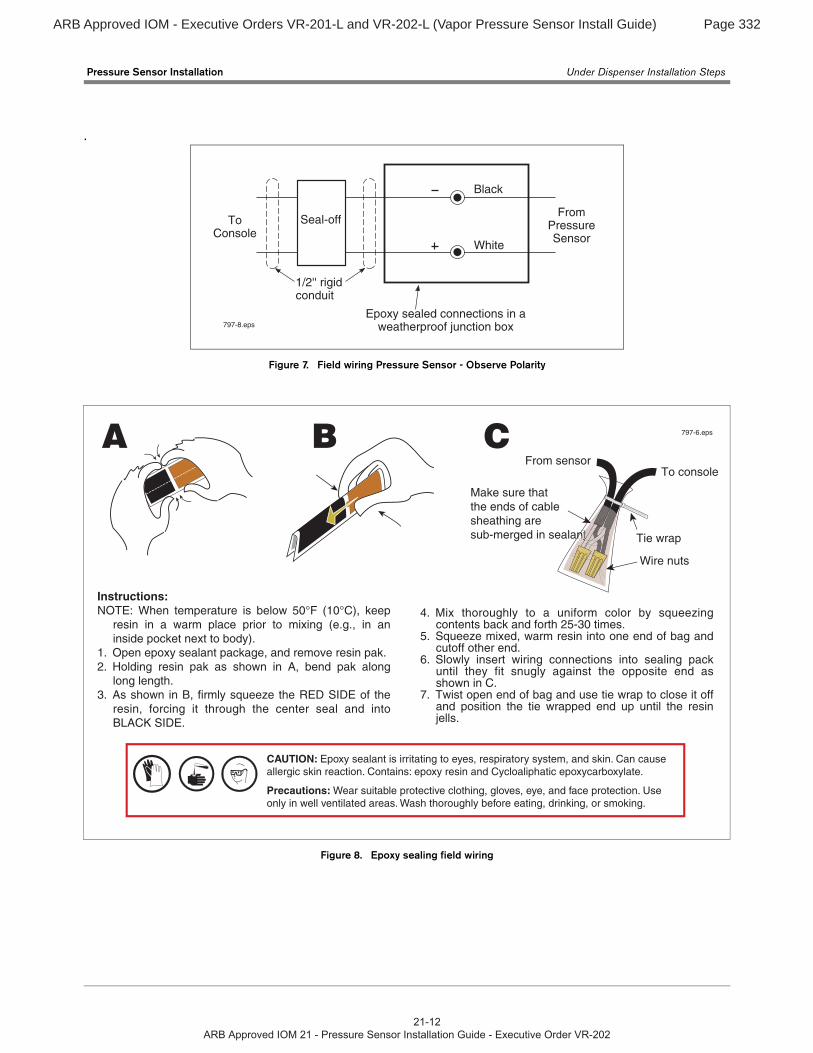
Figure 7. Field wiring Pressure Sensor - Observe Polarity
Figure 8. Epoxy sealing field wiring
Black
ToConsole
FromPressureSensor
Epoxy sealed connections in aweatherproof junction box
1/2'' rigidconduit
Seal-off
797-8.eps
White
797-6.eps
To console
Tie wrap
Wire nuts
From sensorA CB
Make sure that the ends of cable sheathing are sub-merged in sealantntntttnt
Instructions:NOTE: When temperature is below 50°F (10°C), keep
resin in a warm place prior to mixing (e.g., in an inside pocket next to body).
1. Open epoxy sealant package, and remove resin pak.2. Holding resin pak as shown in A, bend pak along
long length.3. As shown in B, firmly squeeze the RED SIDE of the
resin, forcing it through the center seal and into BLACK SIDE.
4. Mix thoroughly to a uniform color by squeezing contents back and forth 25-30 times.
5. Squeeze mixed, warm resin into one end of bag and cutoff other end.
6. Slowly insert wiring connections into sealing pack until they fit snugly against the opposite end as shown in C.
7. Twist open end of bag and use tie wrap to close it off and position the tie wrapped end up until the resin jells.
CAUTION: Epoxy sealant is irritating to eyes, respiratory system, and skin. Can cause allergic skin reaction. Contains: epoxy resin and Cycloaliphatic epoxycarboxylate.
Precautions: Wear suitable protective clothing, gloves, eye, and face protection. Use only in well ventilated areas. Wash thoroughly before eating, drinking, or smoking.
ARB Approved IOM - Executive Orders VR-201-L and VR-202-L (Vapor Pressure Sensor Install Guide) Page 333
Pressure Sensor Installation Vapor Vent Stack Installation Step
13
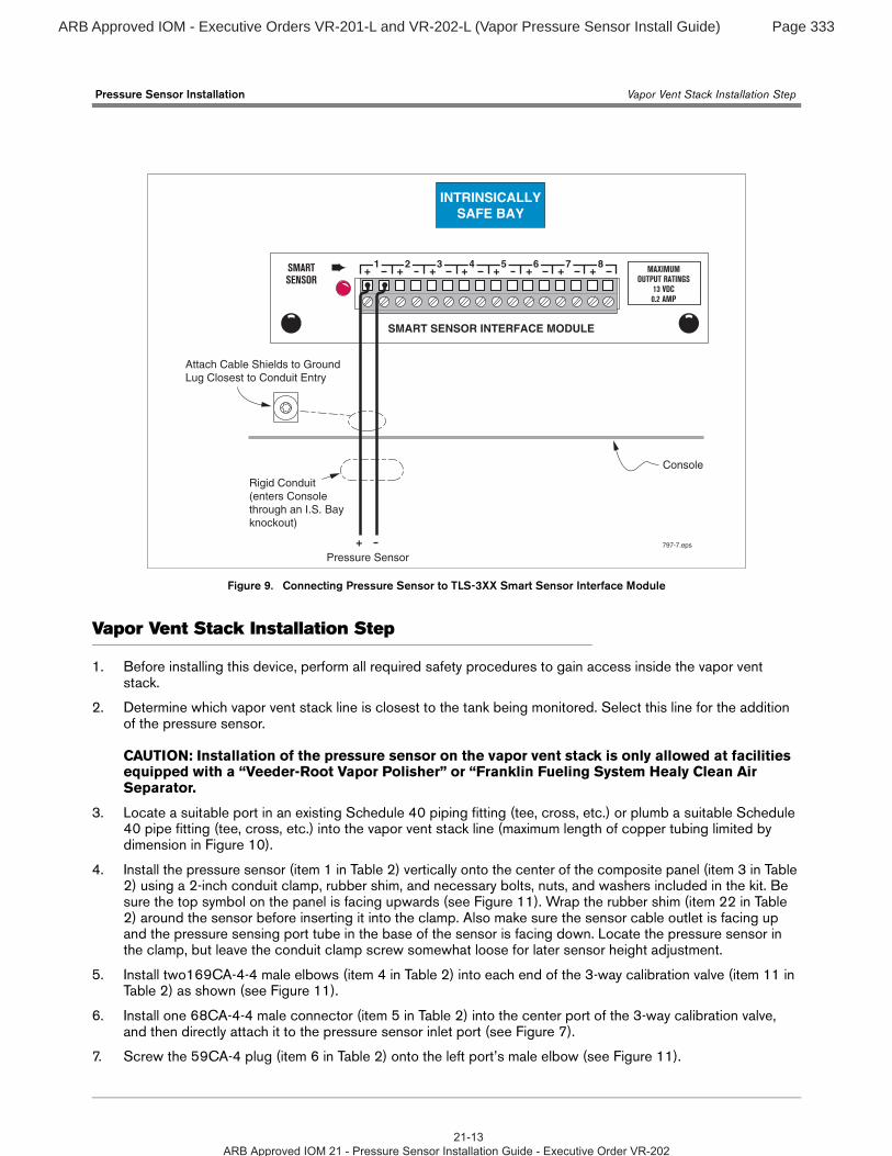
Figure 9. Connecting Pressure Sensor to TLS-3XX Smart Sensor Interface Module
Vapor Vent Stack Installation Step
1. Before installing this device, perform all required safety procedures to gain access inside the vapor vent stack.
2. Determine which vapor vent stack line is closest to the tank being monitored. Select this line for the addition of the pressure sensor.
CAUTION: Installation of the pressure sensor on the vapor vent stack is only allowed at facilities equipped with a “Veeder-Root Vapor Polisher” or “Franklin Fueling System Healy Clean Air Separator.
3. Locate a suitable port in an existing Schedule 40 piping fitting (tee, cross, etc.) or plumb a suitable Schedule 40 pipe fitting (tee, cross, etc.) into the vapor vent stack line (maximum length of copper tubing limited by dimension in Figure 10).
4. Install the pressure sensor (item 1 in Table 2) vertically onto the center of the composite panel (item 3 in Table 2) using a 2-inch conduit clamp, rubber shim, and necessary bolts, nuts, and washers included in the kit. Be sure the top symbol on the panel is facing upwards (see Figure 11). Wrap the rubber shim (item 22 in Table 2) around the sensor before inserting it into the clamp. Also make sure the sensor cable outlet is facing up and the pressure sensing port tube in the base of the sensor is facing down. Locate the pressure sensor in the clamp, but leave the conduit clamp screw somewhat loose for later sensor height adjustment.
5. Install two169CA-4-4 male elbows (item 4 in Table 2) into each end of the 3-way calibration valve (item 11 in Table 2) as shown (see Figure 11).
6. Install one 68CA-4-4 male connector (item 5 in Table 2) into the center port of the 3-way calibration valve, and then directly attach it to the pressure sensor inlet port (see Figure 7).
7. Screw the 59CA-4 plug (item 6 in Table 2) onto the left port’s male elbow (see Figure 11).
Attach Cable Shields to Ground Lug Closest to Conduit Entry
SMARTSENSOR
MAXIMUMOUTPUT RATINGS
13 VDC0.2 AMP
+ + + + + + + +1 2 3 4 5 6 7 8
SMART SENSOR INTERFACE MODULE
797-7.eps
Console
+ Pressure Sensor
Rigid Conduit(enters Consolethrough an I.S. Bay knockout)
INTRINSICALLYSAFE BAY
ARB Approved IOM - Executive Orders VR-201-L and VR-202-L (Vapor Pressure Sensor Install Guide) Page 334
Pressure Sensor Installation Vapor Vent Stack Installation Step
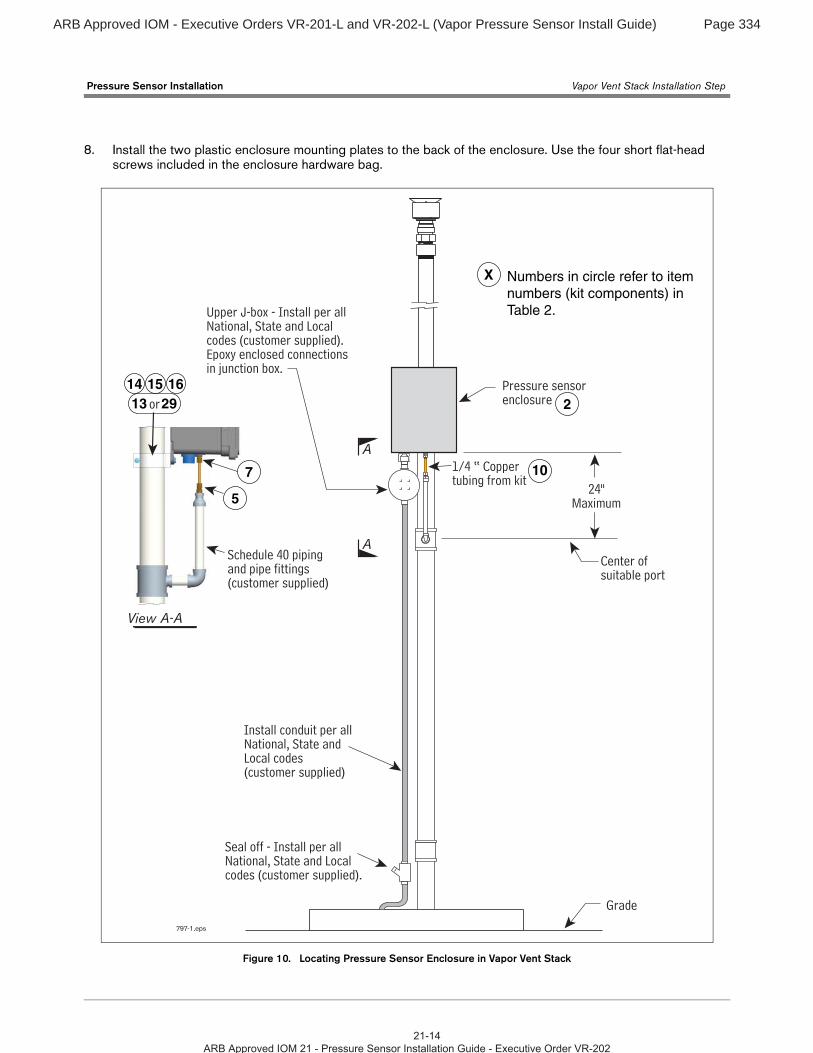
8. Install the two plastic enclosure mounting plates to the back of the enclosure. Use the four short flat-head screws included in the enclosure hardware bag.
Figure 10. Locating Pressure Sensor Enclosure in Vapor Vent Stack
Pressure sensor enclosure
Grade
Install conduit per allNational, State and Local codes (customer supplied)
Center ofsuitable port
1/4 “ Coppertubing from kit
Schedule 40 pipingand pipe fittings (customer supplied)
24"Maximum
797-1.eps
A
A
View A-A
Upper J-box - Install per all National, State and Localcodes (customer supplied). Epoxy enclosed connections in junction box.
2
5
7 10
X Numbers in circle refer to item numbers (kit components) in Table 2.
13 2914 15 16
or
Seal off - Install per allNational, State and Localcodes (customer supplied).
ARB Approved IOM - Executive Orders VR-201-L and VR-202-L (Vapor Pressure Sensor Install Guide) Page 335
Pressure Sensor Installation Vapor Vent Stack Installation Step
1
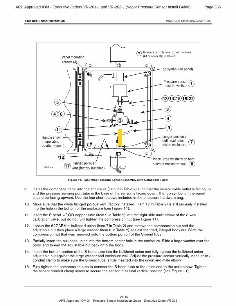
Figure 11. Mounting Pressure Sensor Assembly onto Composite Panel
9. Install the composite panel into the enclosure (item 2 in Table 2) such that the sensor cable outlet is facing up and the pressure sensing port tube in the base of the sensor is facing down. The top symbol on the panel should be facing upward. Use the four short screws included in the enclosure hardware bag.
10. Make sure that the white flanged porous vent (factory installed - item 17 in Table 2) is still securely installed into the hole in the bottom of the enclosure (see Figure 11).
11. Insert the S-bend ¼" OD copper tube (item 9 in Table 2) into the right-side male elbow of the 3-way calibration valve, but do not fully tighten the compression nut (see Figure 11).
12. Locate the 62CABH-4 bulkhead union (item 7 in Table 2) and remove the compression nut and the adjustable nut then place a large washer (item 8 in Table 2) against the fixed, integral body nut. Slide the compression nut that was removed onto the bottom portion of the S-bend tube.
13. Partially insert the bulkhead union into the bottom center hole in the enclosure. Slide a large washer over the body, and thread the adjustable nut back onto the body.
14. Insert the bottom portion of the S-bend tube into the bulkhead union and fully tighten the bulkhead union adjustable nut against the large washer and enclosure wall. Adjust the pressure sensor vertically in the shim / conduit clamp to make sure the S-bend tube is fully inserted into the union and male elbow.
15. Fully tighten the compression nuts to connect the S-bend tube to the union and to the male elbow. Tighten the sensor conduit clamp screw to secure the sensor in its final vertical position (see Figure 11).
Pressure sensormust be vertical
Top symbol (on panel)
Handle shownin operating position (down)
Panel mountingscrews (4)
797-2.eps
Place large washers on both sides of enclosure wall.Flanged porous
vent (factory installed)
7
1
9
4
36
5
11
12
13 14 15 16 22
4
X
17 8
Numbers in circle refer to item numbers (kit components) in Table 2.
Longer portion of bulkhead unioninside enclosure.
ARB Approved IOM - Executive Orders VR-201-L and VR-202-L (Vapor Pressure Sensor Install Guide) Page 336
Pressure Sensor Installation Vapor Vent Stack Installation Step
16. Mount the plastic enclosure onto the vapor vent stack or suitable rigid structure ABOVE the vapor vent stack port using two conduit clamps (for 2" or 3" pipe), bolts, nuts, and washers included, or use other customer supplied suitable mounting hardware (Example: Unistrut®). Leave the mounting hardware somewhat loose for later enclosure height adjustment (see Figure 10).
17. Measure, fabricate, and install customer supplied pipe and pipe fittings between the vapor vent stack port and within a few inches of the bulkhead union in the bottom of the enclosure.
18. Install one 68CA-4-4 male connector (item 5 in Table 2) onto the top of the new pipe (see View A-A, Figure 10).
19. Measure, fabricate, and install ¼" OD copper tubing (item 10 in Table 2) between the bulkhead union and the male connector. Adjust the enclosure vertically on vent pipe to make sure the copper tube is fully inserted into the bulk head union and male connector.
20. Fully tighten the compression nuts to secure the fabricated tube to the bulkhead union and to the male connector. Tighten the enclosure mounting hardware to secure the enclosure in its final vertical position.
Note: Important! All plumbing’s pitch to drain should be 1/4" vertical per 12" horizontal to eliminate any potential liquid traps.
21. Make sure the valve’s handle is set to connect the sensor to the vapor vent stack and not to the capped (ambient) port.
22. Install two tamper-resistant screws from the enclosure hardware bag into the two holes on the enclosure door (if not already installed) using a Torx bit for tamper-resistant screws. Discard any remaining items in the enclosure hardware bag.
23. Install ½" electrical conduit from the conduit hub in the bottom of the enclosure to the customer supplied weather-proof junction box (see Figure 10).
24. Route the cable from the pressure sensor to the junction box under the enclosure. Observing polarity, connect the sensor wiring to the field wiring from console and cap with wire nuts (see Figure 10).
25. Seal wire nuts in epoxy sealant following the instructions in Figure 8.
26. Push the epoxy sealed bag into the junction box. Replace and tighten the junction box cover.
27. Terminate field wiring into TLS Console and connect to Smart Sensor Module (TLS console - Figure 9). Note: observe polarity! The cable length between the console and sensor must not exceed the distance stated in the TLS-3XX Site Prep manual (P/N 576013-879).
Note: Intrinsically safe devices must be installed in accordance with Article 504 of the National Electrical Code, ANSI/NFPA 70, for installation in the United States, or Section 18 of the Canadian Electrical Code for installations in Canada.
This intrinsically safe Pressure Sensor (P/N 331946-001), has only been evaluated for connection to a UL listed TLS-3XX Liquid Level Gauge / Leak Detector.
Conductors of different intrinsically safe circuits run in the same cable/conduit must have at least 0.01 inch (0.25 mm) of insulation.
28. After the Pressure Sensor is installed, pressurize the tank ullage space and vapor piping to at least 2 inches WC and test for leaks using leak detection solution.
29. Close the enclosure door and secure by threading the tamper-resistant screws into the enclosure body using a Torx bit for tamper-resistant screws.
30. Affix the eVRgreen label (item 30 in Table 2) to the enclosure door as desired.
ARB Approved IOM - Executive Orders VR-201-L and VR-202-L (Vapor Pressure Sensor Install Guide) Page 337
For technical support, sales orother assistance, please visit:
www.veeder.com