vPC Peer Switch Deployment Options
12
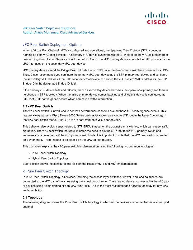
vPC Peer Switch Deployment Options Author: Anees Mohamed, Cisco Advanced Services vPC Peer Switch Deployment Options When a Virtual Port Channel (vPC) is configured and operational, the Spanning Tree Protocol (STP) continues running on both vPC peer devices. The primary vPC device synchronizes the STP state on the vPC secondary peer device using Cisco Fabric Services over Ethernet (CFSoE). The vPC primary device controls the STP process for the vPC interfaces on the secondary vPC peer device. vPC primary devices send the Bridge Protocol Data Units (BPDUs) to the downstream switches connected via vPCs. Thus, Cisco recommends you configure the primary vPC peer device as the STP primary root device and configure the secondary VPC device as the STP secondary root device. vPC uses the vPC system MAC address as the STP Bridge ID in the designated Bridge ID field. If the primary vPC device fails and reloads, the vPC secondary device becomes the operational primary and there is no change in STP topology. When the failed primary device comes back up and since this device is configured as STP root, STP convergence occurs which can cause traffic interruption. 1.1 vPC Peer Switch The vPC peer switch is introduced to address performance concerns around these STP convergence events. This feature allows a pair of Cisco Nexus 7000 Series devices to appear as a single STP root in the Layer 2 topology. In the vPC peer switch mode, STP BPDUs are sent from both vPC peer devices. This behavior also avoids issues related to STP BPDU timeout on the downstream switches, which can cause traffic disruption. The vPC peer switch feature eliminates the need to pin the STP root to the vPC primary switch and improves vPC convergence if the vPC primary switch fails. It is important to note that the vPC peer switch is needed only when the STP root needs to be placed on the vPC pair of devices. This document explains the vPC peer switch implementation using the following two common topologies: ● Pure Peer Switch Topology ● Hybrid Peer Switch Topology Each section shows the configurations for both the Rapid PVST+ and MST implementation. 2. Pure Peer Switch Topology In Pure Peer Switch Topology, all devices, including the access layer switches, firewall, and load balancers, are connected to the vPC pair of switches using the virtual port channel. There are no devices connected to the vPC pair of devices using single homed or non-vPC trunk links. This is the most recommended network topology for any vPC implementation. 2.1 Topology The following diagram shows the Pure Peer Switch Topology in which all the devices are connected via a virtual port channel.
Transcript of vPC Peer Switch Deployment Options
vPC Peer Switch Deployment Options
Author: Anees Mohamed, Cisco Advanced Services
vPC Peer Switch Deployment Options
When a Virtual Port Channel (vPC) is configured and operational, the Spanning Tree Protocol (STP) continues
running on both vPC peer devices. The primary vPC device synchronizes the STP state on the vPC secondary peer
device using Cisco Fabric Services over Ethernet (CFSoE). The vPC primary device controls the STP process for the
vPC interfaces on the secondary vPC peer device.
vPC primary devices send the Bridge Protocol Data Units (BPDUs) to the downstream switches connected via vPCs.
Thus, Cisco recommends you configure the primary vPC peer device as the STP primary root device and configure
the secondary VPC device as the STP secondary root device. vPC uses the vPC system MAC address as the STP
Bridge ID in the designated Bridge ID field.
If the primary vPC device fails and reloads, the vPC secondary device becomes the operational primary and there is
no change in STP topology. When the failed primary device comes back up and since this device is configured as
STP root, STP convergence occurs which can cause traffic interruption.
1.1 vPC Peer Switch
The vPC peer switch is introduced to address performance concerns around these STP convergence events. This
feature allows a pair of Cisco Nexus 7000 Series devices to appear as a single STP root in the Layer 2 topology. In
the vPC peer switch mode, STP BPDUs are sent from both vPC peer devices.
This behavior also avoids issues related to STP BPDU timeout on the downstream switches, which can cause traffic
disruption. The vPC peer switch feature eliminates the need to pin the STP root to the vPC primary switch and
improves vPC convergence if the vPC primary switch fails. It is important to note that the vPC peer switch is needed
only when the STP root needs to be placed on the vPC pair of devices.
This document explains the vPC peer switch implementation using the following two common topologies:
● Pure Peer Switch Topology
● Hybrid Peer Switch Topology
Each section shows the configurations for both the Rapid PVST+ and MST implementation.
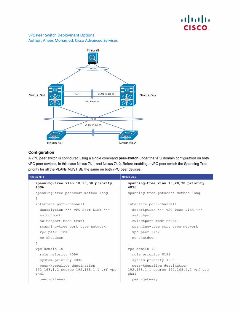
2. Pure Peer Switch Topology
In Pure Peer Switch Topology, all devices, including the access layer switches, firewall, and load balancers, are
connected to the vPC pair of switches using the virtual port channel. There are no devices connected to the vPC pair
of devices using single homed or non-vPC trunk links. This is the most recommended network topology for any vPC
implementation.
2.1 Topology
The following diagram shows the Pure Peer Switch Topology in which all the devices are connected via a virtual port
channel.
vPC Peer Switch Deployment Options
Author: Anees Mohamed, Cisco Advanced Services
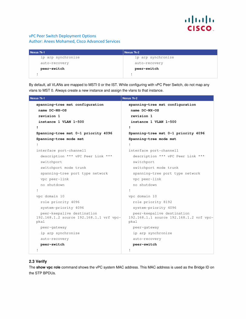
Configuration
A vPC peer switch is configured using a single command peer-switch under the vPC domain configuration on both
vPC peer devices, in this case Nexus 7k-1 and Nexus 7k-2. Before enabling a vPC peer switch the Spanning Tree
priority for all the VLANs MUST BE the same on both vPC peer devices.
Nexus 7k-1 Nexus 7k-2
spanning-tree vlan 10,20,30 priority
4096
spanning-tree pathcost method long
!
interface port-channel1
description *** vPC Peer Link ***
switchport
switchport mode trunk
spanning-tree port type network
vpc peer-link
no shutdown
!
vpc domain 10
role priority 4096
system-priority 4096
peer-keepalive destination
192.168.1.2 source 192.168.1.1 vrf vpc-
pkal
peer-gateway
spanning-tree vlan 10,20,30 priority
4096
spanning-tree pathcost method long
!
interface port-channel1
description *** vPC Peer Link ***
switchport
switchport mode trunk
spanning-tree port type network
vpc peer-link
no shutdown
!
vpc domain 10
role priority 8192
system-priority 4096
peer-keepalive destination
192.168.1.1 source 192.168.1.2 vrf vpc-
pkal
peer-gateway
vPC Peer Switch Deployment Options
Author: Anees Mohamed, Cisco Advanced Services
Nexus 7k-1 Nexus 7k-2
ip arp synchronize
auto-recovery
peer-switch
!
ip arp synchronize
auto-recovery
peer-switch
!
By default, all VLANs are mapped to MSTI 0 or the IST. While configuring with vPC Peer Switch, do not map any
vlans to MST 0. Always create a new instance and assign the vlans to that instance.
Nexus 7k-1 Nexus 7k-2
spanning-tree mst configuration
name DC-NX-OS
revision 1
instance 1 VLAN 1-500
!
Spanning-tree mst 0-1 priority 4096
Spanning-tree mode mst
!
interface port-channel1
description *** vPC Peer Link ***
switchport
switchport mode trunk
spanning-tree port type network
vpc peer-link
no shutdown
!
vpc domain 10
role priority 4096
system-priority 4096
peer-keepalive destination
192.168.1.2 source 192.168.1.1 vrf vpc-
pkal
peer-gateway
ip arp synchronize
auto-recovery
peer-switch
!
spanning-tree mst configuration
name DC-NX-OS
revision 1
instance 1 VLAN 1-500
!
Spanning-tree mst 0-1 priority 4096
Spanning-tree mode mst
!
interface port-channel1
description *** vPC Peer Link ***
switchport
switchport mode trunk
spanning-tree port type network
vpc peer-link
no shutdown
!
vpc domain 10
role priority 8192
system-priority 4096
peer-keepalive destination
192.168.1.1 source 192.168.1.2 vrf vpc-
pkal
peer-gateway
ip arp synchronize
auto-recovery
peer-switch
!
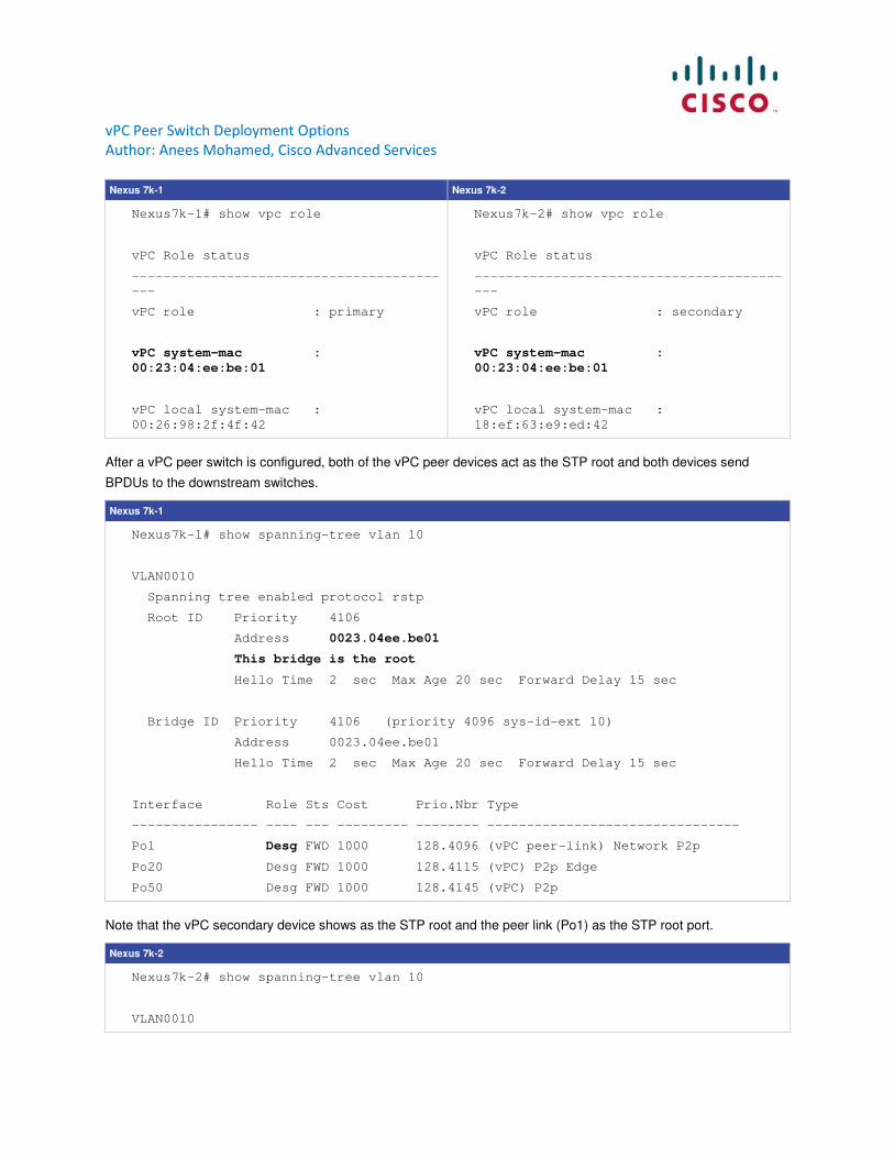
2.3 Verify
The show vpc role command shows the vPC system MAC address. This MAC address is used as the Bridge ID on
the STP BPDUs.
vPC Peer Switch Deployment Options
Author: Anees Mohamed, Cisco Advanced Services
Nexus 7k-1 Nexus 7k-2
Nexus7k-1# show vpc role
vPC Role status
---------------------------------------
---
vPC role : primary
vPC system-mac :
00:23:04:ee:be:01
vPC local system-mac :
00:26:98:2f:4f:42
Nexus7k-2# show vpc role
vPC Role status
---------------------------------------
---
vPC role : secondary
vPC system-mac :
00:23:04:ee:be:01
vPC local system-mac :
18:ef:63:e9:ed:42
After a vPC peer switch is configured, both of the vPC peer devices act as the STP root and both devices send
BPDUs to the downstream switches.
Nexus 7k-1
Nexus7k-1# show spanning-tree vlan 10
VLAN0010
Spanning tree enabled protocol rstp
Root ID Priority 4106
Address 0023.04ee.be01
This bridge is the root
Hello Time 2 sec Max Age 20 sec Forward Delay 15 sec
Bridge ID Priority 4106 (priority 4096 sys-id-ext 10)
Address 0023.04ee.be01
Hello Time 2 sec Max Age 20 sec Forward Delay 15 sec
Interface Role Sts Cost Prio.Nbr Type
---------------- ---- --- --------- -------- --------------------------------
Po1 Desg FWD 1000 128.4096 (vPC peer-link) Network P2p
Po20 Desg FWD 1000 128.4115 (vPC) P2p Edge
Po50 Desg FWD 1000 128.4145 (vPC) P2p
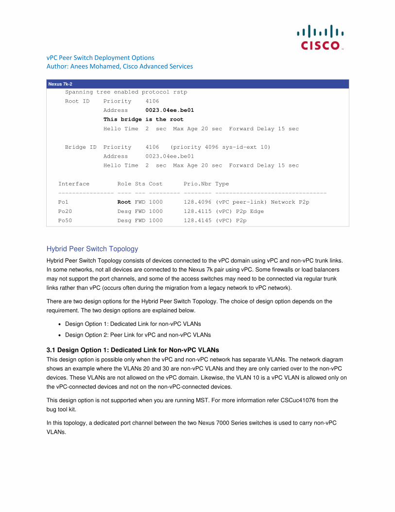
Note that the vPC secondary device shows as the STP root and the peer link (Po1) as the STP root port.
Nexus 7k-2
Nexus7k-2# show spanning-tree vlan 10
VLAN0010
vPC Peer Switch Deployment Options
Author: Anees Mohamed, Cisco Advanced Services
Nexus 7k-2
Spanning tree enabled protocol rstp
Root ID Priority 4106
Address 0023.04ee.be01
This bridge is the root
Hello Time 2 sec Max Age 20 sec Forward Delay 15 sec
Bridge ID Priority 4106 (priority 4096 sys-id-ext 10)
Address 0023.04ee.be01
Hello Time 2 sec Max Age 20 sec Forward Delay 15 sec
Interface Role Sts Cost Prio.Nbr Type
---------------- ---- --- --------- -------- --------------------------------
Po1 Root FWD 1000 128.4096 (vPC peer-link) Network P2p
Po20 Desg FWD 1000 128.4115 (vPC) P2p Edge
Po50 Desg FWD 1000 128.4145 (vPC) P2p
Hybrid Peer Switch Topology
Hybrid Peer Switch Topology consists of devices connected to the vPC domain using vPC and non-vPC trunk links.
In some networks, not all devices are connected to the Nexus 7k pair using vPC. Some firewalls or load balancers
may not support the port channels, and some of the access switches may need to be connected via regular trunk
links rather than vPC (occurs often during the migration from a legacy network to vPC network).
There are two design options for the Hybrid Peer Switch Topology. The choice of design option depends on the
requirement. The two design options are explained below.
● Design Option 1: Dedicated Link for non-vPC VLANs
● Design Option 2: Peer Link for vPC and non-vPC VLANs
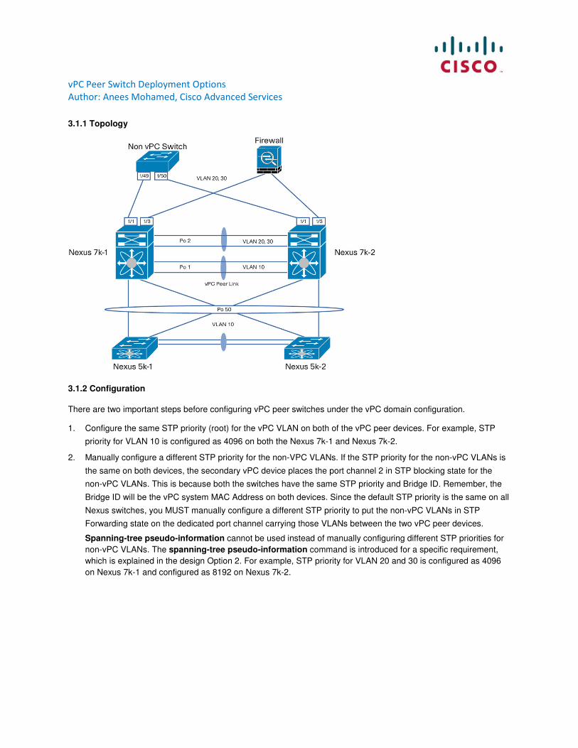
3.1 Design Option 1: Dedicated Link for Non-vPC VLANs
This design option is possible only when the vPC and non-vPC network has separate VLANs. The network diagram
shows an example where the VLANs 20 and 30 are non-vPC VLANs and they are only carried over to the non-vPC
devices. These VLANs are not allowed on the vPC domain. Likewise, the VLAN 10 is a vPC VLAN is allowed only on
the vPC-connected devices and not on the non-vPC-connected devices.
This design option is not supported when you are running MST. For more information refer CSCuc41076 from the
bug tool kit.
In this topology, a dedicated port channel between the two Nexus 7000 Series switches is used to carry non-vPC
VLANs.
vPC Peer Switch Deployment Options
Author: Anees Mohamed, Cisco Advanced Services
3.1.1 Topology
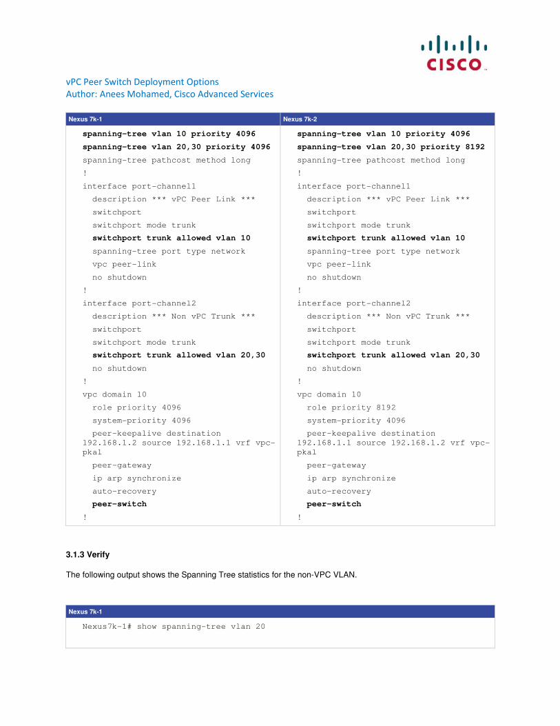
3.1.2 Configuration
There are two important steps before configuring vPC peer switches under the vPC domain configuration.
1. Configure the same STP priority (root) for the vPC VLAN on both of the vPC peer devices. For example, STP
priority for VLAN 10 is configured as 4096 on both the Nexus 7k-1 and Nexus 7k-2.
2. Manually configure a different STP priority for the non-VPC VLANs. If the STP priority for the non-vPC VLANs is
the same on both devices, the secondary vPC device places the port channel 2 in STP blocking state for the
non-vPC VLANs. This is because both the switches have the same STP priority and Bridge ID. Remember, the
Bridge ID will be the vPC system MAC Address on both devices. Since the default STP priority is the same on all
Nexus switches, you MUST manually configure a different STP priority to put the non-vPC VLANs in STP
Forwarding state on the dedicated port channel carrying those VLANs between the two vPC peer devices.
Spanning-tree pseudo-information cannot be used instead of manually configuring different STP priorities for
non-vPC VLANs. The spanning-tree pseudo-information command is introduced for a specific requirement,
which is explained in the design Option 2. For example, STP priority for VLAN 20 and 30 is configured as 4096
on Nexus 7k-1 and configured as 8192 on Nexus 7k-2.
vPC Peer Switch Deployment Options
Author: Anees Mohamed, Cisco Advanced Services
Nexus 7k-1 Nexus 7k-2
spanning-tree vlan 10 priority 4096
spanning-tree vlan 20,30 priority 4096
spanning-tree pathcost method long
!
interface port-channel1
description *** vPC Peer Link ***
switchport
switchport mode trunk
switchport trunk allowed vlan 10
spanning-tree port type network
vpc peer-link
no shutdown
!
interface port-channel2
description *** Non vPC Trunk ***
switchport
switchport mode trunk
switchport trunk allowed vlan 20,30
no shutdown
!
vpc domain 10
role priority 4096
system-priority 4096
peer-keepalive destination
192.168.1.2 source 192.168.1.1 vrf vpc-
pkal
peer-gateway
ip arp synchronize
auto-recovery
peer-switch
!
spanning-tree vlan 10 priority 4096
spanning-tree vlan 20,30 priority 8192
spanning-tree pathcost method long
!
interface port-channel1
description *** vPC Peer Link ***
switchport
switchport mode trunk
switchport trunk allowed vlan 10
spanning-tree port type network
vpc peer-link
no shutdown
!
interface port-channel2
description *** Non vPC Trunk ***
switchport
switchport mode trunk
switchport trunk allowed vlan 20,30
no shutdown
!
vpc domain 10
role priority 8192
system-priority 4096
peer-keepalive destination
192.168.1.1 source 192.168.1.2 vrf vpc-
pkal
peer-gateway
ip arp synchronize
auto-recovery
peer-switch
!
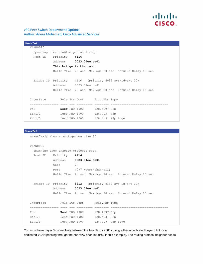
3.1.3 Verify
The following output shows the Spanning Tree statistics for the non-VPC VLAN.
Nexus 7k-1
Nexus7k-1# show spanning-tree vlan 20
vPC Peer Switch Deployment Options
Author: Anees Mohamed, Cisco Advanced Services
Nexus 7k-1
VLAN0020
Spanning tree enabled protocol rstp
Root ID Priority 4116
Address 0023.04ee.be01
This bridge is the root
Hello Time 2 sec Max Age 20 sec Forward Delay 15 sec
Bridge ID Priority 4116 (priority 4096 sys-id-ext 20)
Address 0023.04ee.be01
Hello Time 2 sec Max Age 20 sec Forward Delay 15 sec
Interface Role Sts Cost Prio.Nbr Type
---------------- ---- --- --------- -------- --------------------------------
Po2 Desg FWD 1000 128.4097 P2p
Eth1/1 Desg FWD 1000 128.413 P2p
Eth1/3 Desg FWD 1000 128.415 P2p Edge
Nexus 7k-2
Nexus7k-2# show spanning-tree vlan 20
VLAN0020
Spanning tree enabled protocol rstp
Root ID Priority 4116
Address 0023.04ee.be01
Cost 2
Port 4097 (port-channel2)
Hello Time 2 sec Max Age 20 sec Forward Delay 15 sec
Bridge ID Priority 8212 (priority 8192 sys-id-ext 20)
Address 0023.04ee.be01
Hello Time 2 sec Max Age 20 sec Forward Delay 15 sec
Interface Role Sts Cost Prio.Nbr Type
---------------- ---- --- --------- -------- --------------------------------
Po2 Root FWD 1000 128.4097 P2p
Eth1/1 Desg FWD 1000 128.413 P2p
Eth1/3 Desg FWD 1000 128.415 P2p Edge
You must have Layer 3 connectivity between the two Nexus 7000s using either a dedicated Layer 3 link or a
dedicated VLAN passing through the non-vPC peer link (Po2 in this example). The routing protocol neighbor has to
vPC Peer Switch Deployment Options
Author: Anees Mohamed, Cisco Advanced Services
be established on this dedicated Layer 3 link. This is required if the vPC secondary switch is the HSRP active for the
non-vPC VLANs.
For example, if the peer link goes down, the vPC secondary switch will shut down the downstream vPC port channels
and the SVIs for the VLANs passing through the peer link (in this case VLAN 10). However, it will not shutdown the
SVI for the non-vPC VLANs and if vPC secondary device is the HSRP active for VLAN 20. If you do not have a Layer
3 routing adjacency between the two switches, it will black hole the traffic arriving from VLAN 20.
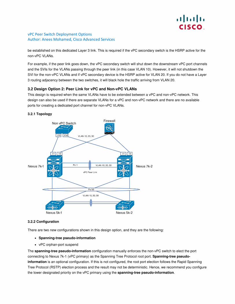
3.2 Design Option 2: Peer Link for vPC and Non-vPC VLANs
This design is required when the same VLANs have to be extended between a vPC and non-vPC network. This
design can also be used if there are separate VLANs for a vPC and non-vPC network and there are no available
ports for creating a dedicated port channel for non-vPC VLANs.
3.2.1 Topology
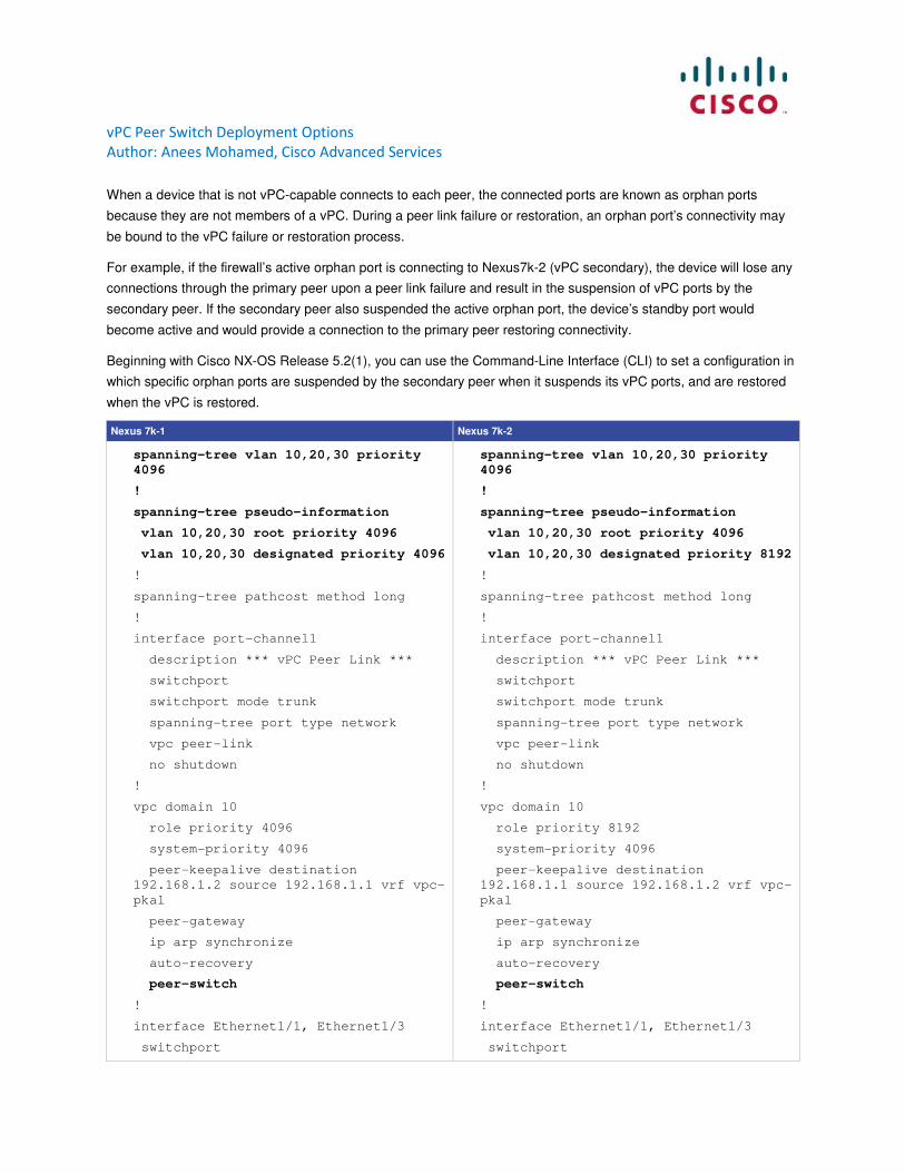
3.2.2 Configuration
There are two new configurations shown in this design option, and they are the following:
● Spanning-tree pseudo-information
● vPC orphan-port suspend
The spanning-tree pseudo-information configuration manually enforces the non-vPC switch to elect the port
connecting to Nexus 7k-1 (vPC primary) as the Spanning Tree Protocol root port. Spanning-tree pseudo-
information is an optional configuration. If this is not configured, the root port election follows the Rapid Spanning
Tree Protocol (RSTP) election process and the result may not be deterministic. Hence, we recommend you configure
the lower designated priority on the vPC primary using the spanning-tree pseudo-information.
vPC Peer Switch Deployment Options
Author: Anees Mohamed, Cisco Advanced Services
When a device that is not vPC-capable connects to each peer, the connected ports are known as orphan ports
because they are not members of a vPC. During a peer link failure or restoration, an orphan port’s connectivity may
be bound to the vPC failure or restoration process.
For example, if the firewall’s active orphan port is connecting to Nexus7k-2 (vPC secondary), the device will lose any
connections through the primary peer upon a peer link failure and result in the suspension of vPC ports by the
secondary peer. If the secondary peer also suspended the active orphan port, the device’s standby port would
become active and would provide a connection to the primary peer restoring connectivity.
Beginning with Cisco NX-OS Release 5.2(1), you can use the Command-Line Interface (CLI) to set a configuration in
which specific orphan ports are suspended by the secondary peer when it suspends its vPC ports, and are restored
when the vPC is restored.
Nexus 7k-1 Nexus 7k-2
spanning-tree vlan 10,20,30 priority
4096
!
spanning-tree pseudo-information
vlan 10,20,30 root priority 4096
vlan 10,20,30 designated priority 4096
!
spanning-tree pathcost method long
!
interface port-channel1
description *** vPC Peer Link ***
switchport
switchport mode trunk
spanning-tree port type network
vpc peer-link
no shutdown
!
vpc domain 10
role priority 4096
system-priority 4096
peer-keepalive destination
192.168.1.2 source 192.168.1.1 vrf vpc-
pkal
peer-gateway
ip arp synchronize
auto-recovery
peer-switch
!
interface Ethernet1/1, Ethernet1/3
switchport
spanning-tree vlan 10,20,30 priority
4096
!
spanning-tree pseudo-information
vlan 10,20,30 root priority 4096
vlan 10,20,30 designated priority 8192
!
spanning-tree pathcost method long
!
interface port-channel1
description *** vPC Peer Link ***
switchport
switchport mode trunk
spanning-tree port type network
vpc peer-link
no shutdown
!
vpc domain 10
role priority 8192
system-priority 4096
peer-keepalive destination
192.168.1.1 source 192.168.1.2 vrf vpc-
pkal
peer-gateway
ip arp synchronize
auto-recovery
peer-switch
!
interface Ethernet1/1, Ethernet1/3
switchport
vPC Peer Switch Deployment Options
Author: Anees Mohamed, Cisco Advanced Services
Nexus 7k-1 Nexus 7k-2
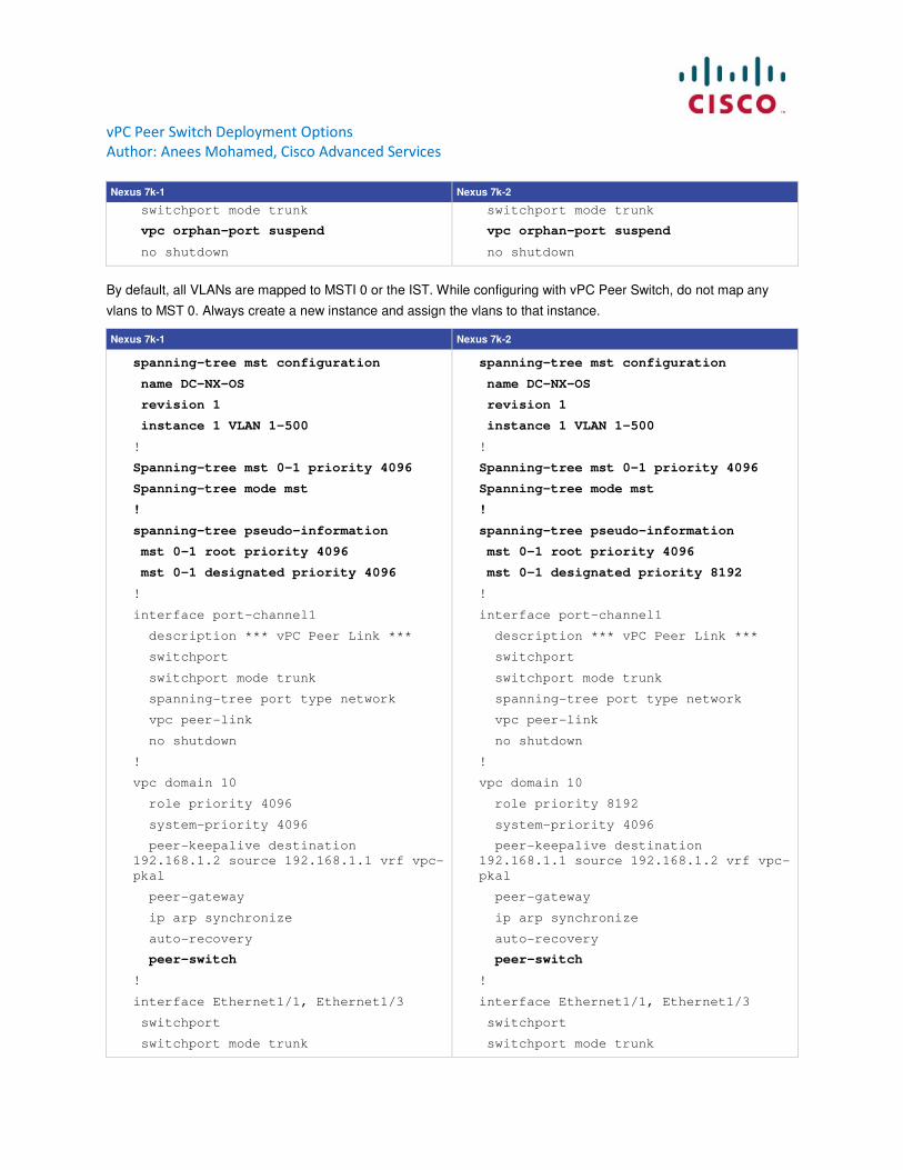
switchport mode trunk
vpc orphan-port suspend
no shutdown
switchport mode trunk
vpc orphan-port suspend
no shutdown
By default, all VLANs are mapped to MSTI 0 or the IST. While configuring with vPC Peer Switch, do not map any
vlans to MST 0. Always create a new instance and assign the vlans to that instance.
Nexus 7k-1 Nexus 7k-2
spanning-tree mst configuration
name DC-NX-OS
revision 1
instance 1 VLAN 1-500
!
Spanning-tree mst 0-1 priority 4096
Spanning-tree mode mst
!
spanning-tree pseudo-information
mst 0-1 root priority 4096
mst 0-1 designated priority 4096
!
interface port-channel1
description *** vPC Peer Link ***
switchport
switchport mode trunk
spanning-tree port type network
vpc peer-link
no shutdown
!
vpc domain 10
role priority 4096
system-priority 4096
peer-keepalive destination
192.168.1.2 source 192.168.1.1 vrf vpc-
pkal
peer-gateway
ip arp synchronize
auto-recovery
peer-switch
!
interface Ethernet1/1, Ethernet1/3
switchport
switchport mode trunk
spanning-tree mst configuration
name DC-NX-OS
revision 1
instance 1 VLAN 1-500
!
Spanning-tree mst 0-1 priority 4096
Spanning-tree mode mst
!
spanning-tree pseudo-information
mst 0-1 root priority 4096
mst 0-1 designated priority 8192
!
interface port-channel1
description *** vPC Peer Link ***
switchport
switchport mode trunk
spanning-tree port type network
vpc peer-link
no shutdown
!
vpc domain 10
role priority 8192
system-priority 4096
peer-keepalive destination
192.168.1.1 source 192.168.1.2 vrf vpc-
pkal
peer-gateway
ip arp synchronize
auto-recovery
peer-switch
!
interface Ethernet1/1, Ethernet1/3
switchport
switchport mode trunk
vPC Peer Switch Deployment Options
Author: Anees Mohamed, Cisco Advanced Services
Nexus 7k-1 Nexus 7k-2
vpc orphan-port suspend
no shutdown
vpc orphan-port suspend
no shutdown
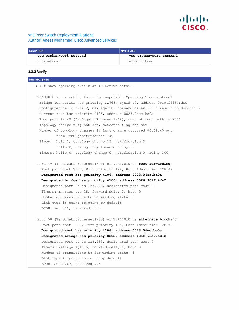
3.2.3 Verify
Non-vPC Switch
4948# show spanning-tree vlan 10 active detail
VLAN0010 is executing the rstp compatible Spanning Tree protocol
Bridge Identifier has priority 32768, sysid 10, address 0019.5629.fdc0
Configured hello time 2, max age 20, forward delay 15, transmit hold-count 6
Current root has priority 4106, address 0023.04ee.be0a
Root port is 49 (TenGigabitEthernet1/49), cost of root path is 2000
Topology change flag not set, detected flag not set
Number of topology changes 14 last change occurred 00:02:45 ago
from TenGigabitEthernet1/49
Times: hold 1, topology change 35, notification 2
hello 2, max age 20, forward delay 15
Timers: hello 0, topology change 0, notification 0, aging 300
Port 49 (TenGigabitEthernet1/49) of VLAN0010 is root forwarding
Port path cost 2000, Port priority 128, Port Identifier 128.49.
Designated root has priority 4106, address 0023.04ee.be0a
Designated bridge has priority 4106, address 0026.982f.4f42
Designated port id is 128.278, designated path cost 0
Timers: message age 16, forward delay 0, hold 0
Number of transitions to forwarding state: 3
Link type is point-to-point by default
BPDU: sent 19, received 1055
Port 50 (TenGigabitEthernet1/50) of VLAN0010 is alternate blocking
Port path cost 2000, Port priority 128, Port Identifier 128.50.
Designated root has priority 4106, address 0023.04ee.be0a
Designated bridge has priority 8202, address 18ef.63e9.ed42
Designated port id is 128.283, designated path cost 0
Timers: message age 16, forward delay 0, hold 0
Number of transitions to forwarding state: 3
Link type is point-to-point by default
BPDU: sent 287, received 773