
VORTEX PARTFILL - JDJ Solutions
4
© Jobe Valves P.O Box 17 Matamata New Zealand P: +64 (0)7 880 9090 F: +64 (0)7 880 9099 E: [email protected] W: www.jobevalves.com 100
Transcript of VORTEX PARTFILL - JDJ Solutions
© Jobe Valves P.O Box 17 Matamata New Zealand P: +64 (0)7 880 9090 F: +64 (0)7 880 9099 E: [email protected] W: www.jobevalves.com100
101© Jobe Valves P.O Box 17 Matamata New Zealand P: +64 (0)7 880 9090 F: +64 (0)7 880 9099 E: [email protected] W: www.jobevalves.com
VORTEX PARTFILL PROducT InFO
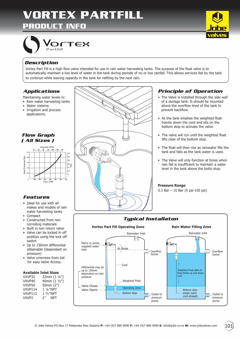
Flow Graph
Description
ApplicationsMaintaining water levels in:• Rain water harvesting tanks• Water cisterns• Irrigation and process applications.
Features• Ideal for use with all makes and models of rain water harvesting tanks• Compact• Constructed from non corroding materials• Built in non return valve• Valve can be locked in off position using the lock off switch• Up to 150mm differential obtainable (dependant on pressure)• Valve unscrews from tail for easy Valve Access.
Available Inlet SizesVXVP32 32mm (1 ¼”)VXVP40 40mm (1 ½”)VXVP50 50mm (2”)VXVP114 1 ¼” NPTVXVP112 1 ½’’ NPTVXVP2 2” NPT
Vortex Part Fill is a high flow valve intended for use in rain water harvesting tanks. The purpose of the float valve is to automatically maintain a low level of water in the tank during periods of no or low rainfall. This allows services fed by the tank to continue while leaving capacity in the tank for refilling by the next rain.
Principle of Operation• The Valve is installed through the side wall of a storage tank. It should be mounted above the overflow level of the tank to prevent backflow.
• As the tank empties the weighted float travels down the cord and sits on the bottom stop to activate the valve.
• The valve will run until the weighted float lifts clear of the bottom stop.
• The float will then rise as rainwater fills the tank and falls as the tank water is used.
• The Valve will only function at times when rain fall is insufficient to maintain a water level in the tank above the botto stop.
Pressure Range0.3 Bar – 10 Bar (5 psi-150 psi)
1.5
1.0
0.5
0 100 200 300 400 500 600 700
2.0
2.5
Flow LPM
Imperial GPM
Inle
t Pre
ssur
e B
ar
20 40 60 80 100 120 140
35
30
25
20
15
10
5
PS
I
( All Sizes )
Vortex Part Fill Operating Zone
Weighted Float able tofloat freely up and down cord
Rainwater Inlet
Mains or pump supplied water inlet
Cord
Weighted Float
Air Break
.
Rainwater Inlet
Typical Installaton
Rain Water Filling Zone

Vortex Dimensions
H
B
F
E
D C
G
A
© Jobe Valves P.O Box 17 Matamata New Zealand P: +64 (0)7 880 9090 F: +64 (0)7 880 9099 E: [email protected] W: www.jobevalves.com102
A
B
C
D
E
F
G
H
108
110
270
31
65
208
62
132
mm inches
4 1/4
4 3/8
10 11/16
1 7/16
2 7/16
8 3/16
2 7/16
5 3/16
Vortex Dimensions Materials
GF Nylon
Acetal
ABS
EPDM
Urethane
304 Stainless Steel
Nitrile
HDPE
Valve Body
White Internal Parts
Arm Assembly
Diaphragm
Seal
Springs, Bolts, Nuts, Pin, Screws
O’Rings
Float
Maximum Temperature of Operation 60ºC, 140ºF
VORTEX PARTFILL dIMEnSIOnS & MATERIALS

103© Jobe Valves P.O Box 17 Matamata New Zealand P: +64 (0)7 880 9090 F: +64 (0)7 880 9099 E: [email protected] W: www.jobevalves.com
2 DESCRIPTION CODE
1
2
3
4
5
6
7
8
9
10
VXPP2010
VXPP2020
VXPP2030
VXPP2040
VXPP2050
VXPP2060
VXPP2070
VXPP2080
VXPP2090
VXPP2100
Actuator Cap6g x 10 S/S Screw Frost Pro Plug Frost Pro O’ring Valve Cap Assembly Damping Spring Bearings (set of two) Actuator Arm Bolt M6 x 65Washer M6 x 12.5
1
21
4
3
4
1
DESCRIPTIONCODE
3
2
CODE: VXVP
1
2
3
4
5
VXPP1010
VXPP1020
VXPP1030
VXPP1040
VXPP1050
Bottom Stop
Weighted Float
Cord
Arm Extension
M5 x 12 Bolt
1
2
3
4
VXPP1
VXPP2
VXPP3
Float Assembly
Cap & Actuator Assembly
Diaphragm Assembly
Detach Base Assembly
DESCRIPTION CODE
VORTEX PARTFILL PARTS IdEnTIFIcATIOn SHEET
2
3
4
DESCRIPTION CODE 4Vortex Retainer
Vortex Base
Vortex O’ring
Vortex Tail 32mm
Vortex Tail 40mm
Vortex Tail 50mm
Vortex Tail 1 ¼” NPT
Vortex Tail 1 ½” NPT
Vortex Tail 2” NPT
1
2
3
4
VXPP4010
VXPP4020
VXPP4030
VXPP4040
VXPP4045
VXPP4050
VXPP4055
VXPP4060
VXPP4065
1
1
23
45
7
8
10
6
5
9


![MULTI-COMPONENT VORTEX SOLUTIONS IN SYMMETRIC COUPLED NONLINEAR … · 2008. 7. 2. · stable vortex solitons have been predicted to exist in media with competing nonlinearities [9]](https://static.fdocuments.in/doc/165x107/60b1cba7dd19ec6a94508763/multi-component-vortex-solutions-in-symmetric-coupled-nonlinear-2008-7-2-stable.jpg)