Vortex Flow Measuring System TI 062D/24/ae PROline prowirl · PDF fileTI 062D/24/ae Vortex...
24
Technical Information TI 062D/24/ae Vortex Flow Measuring System PROline prowirl 72 Reliable Flow Measurement of Gas, Steam and Liquids Application For measuring the volume flow of steam, gases and liquids. For utility and process applications in the chemical, petrochemical, power and district heating industries and in many other industries. Your benefits • Proven capacitive sensor (installed base > 100,000) • Immune to: – Vibration (over 1 g in all axes) – Temperature shock (> 150 K/s) – Dirty media – Water hammer • Process temp. range -330° to +750°F (-200° to +400°C) • Universal: – Compact or remote version – Dualsens version, with two sensors and electronics (for redundancy) – Alloy C-22 version • Connection to all common systems: – HART – PROFIBUS-PA – FOUNDATION Fieldbus • Galvanically isolated pulse output available (for alarm, limit value etc.). • Permanent self-monitoring and diagnosis of electronics and sensor. • Correction of diameter mismatch. • No maintenance, no moving parts, no zero-point drift.
Transcript of Vortex Flow Measuring System TI 062D/24/ae PROline prowirl · PDF fileTI 062D/24/ae Vortex...
Technical InformationTI 062D/24/ae Vortex Flow Measuring System
PROline prowirl 72
Reliable Flow Measurement of Gas, Steam and Liquids
ApplicationFor measuring the volume flow of steam, gases and liquids.For utility and process applications in the chemical, petrochemical, power and district heating industries and in many other industries.
Your benefits
• Proven capacitive sensor (installed base > 100,000)
• Immune to:– Vibration (over 1 g in all axes)– Temperature shock (> 150 K/s)– Dirty media– Water hammer
• Process temp. range -330° to +750°F(-200° to +400°C)
• Universal:– Compact or remote version– Dualsens version, with two sensors
and electronics (for redundancy)– Alloy C-22 version
• Connection to all common systems:– HART– PROFIBUS-PA– FOUNDATION Fieldbus
• Galvanically isolated pulse output available (for alarm, limit value etc.).
• Permanent self-monitoring and diagnosis of electronics and sensor.
• Correction of diameter mismatch.• No maintenance, no moving parts,
no zero-point drift.
PROline Prowirl 72 F, W
2 Endress + Hauser
Function and system design
Measuring principle The operating principle is based on the Karman vortex street. When a fluid flows past a bluff body, vortices are alternately formed on the sides of that body and are then dectached or shed by the flow. The frequency of vortex shedding is proportional to the mean flow velocity and, therefore, to the volumetric flow. Alternating pressure changes caused by the vortices are transmitted by the sensor. The DSC sensor is located behind the bluff body and is well protected from water hammer and temperature or pressure shocks.
The K-factor is used as the proportional constant:
Within the application limits of the device, the K-factor only depends on the geometry of the device. It is independent of the fluid velocity and its properties viscosity and density. In this way, the K-factor is also independent of the type of fluid to be measured, regardless of whether this is steam, a gas or a liquid.The primary measuring signal is already digital (frequency signal) and a linear function of the flow. After manufacturing the meter, the K-factor is determined in the factory by means of calibration and is not subjected to any long term drift or zero point shift.The device does not contain any moving parts and requires no maintenance.
The capacitive sensor
The sensor of a vortex flowmeter has a major influence on the performance, robustness and reliability of the whole measuring system.The Prowirl 72 uses Endress + Hauser's proven and patented capacitive measuring technology, with more than 100,000 Vortex measuring points installed to date world wide.
v
OR K-Factor = pulses
unit volume [dm³]K-Factor = pulses
unit volume [gal]
Due to its internal mechanical balance, the DSC sensor (Differential Switched Capacitance), reads only the pressure pulses caused by the vortices and stays immune to any influence from mechanical pipe line vibrations. The DSC sensor measures low flow rates at low fluid density even when pipe line vibrations are present. Therefore, the Prowirl 72 keeps its wide turndown ratio even under rough operating conditions.Vibrations of at least 1g at frequencies up to 500 Hz in all axes do not affect the flow measurement.Thanks to its mechanical design, the capacitive sensor is especially resistant to temperature shocks and water hammer in steam lines.
Sensor
Seal
Y-Axis
X-Axis
Z-Axis
PROline Prowirl 72 F, W
Endress + Hauser 3
Measuring system The measuring system consist of a sensor and a transmitter.Two versions are available:• Compact version: sensor and transmitter form a mechanical unit.• Remote version: sensor is mounted separate from the transmitter.
Sensor• Prowirl F 1/2” to 12” (DN 15 to 300)
Flanged version (also available as version with two sensors and electronics for redundancy, 1-1/2” to 6” / DN 40 to 150)
• Prowirl W 1/2” to 6” (DN 15 to150)Wafer version
Transmitter• Prowirl 72
Input
Measured variable Volumetric flow (volume flow), is proportional to the frequency of vortex shedding after the bluff body.
The output variables are volume flow or, if the process conditions are non-varying, calculated mass flow or corrected volume flow.
Measuring range The measuring range depends on the fluid and the nominal diameter.
Start of measuring range
Depends on the density and the Reynolds number (Remin = 4,000, Relinear = 20,000). The Reynolds number is dimensionless and indicates the ratio of a fluid's inertial forces to its viscous forces. It is used to characterize the flow. The Reynolds number is calculated as follows:
Re = Reynolds number; Q = Flow; di = Internal diameter; µ = Dynamic viscosity; ρ = Density
Full scale value
• Gas/steam: vmax = 248 ft/s (75 m/s), for 1/2” vmax = 152 ft/s (DN 15: vmax = 46 m/s)• Liquids: vmax = 30 ft/s (9 m/s)
Note! By using the selection and sizing software "Applicator", you can determine the exact values for the fluid you use. The Applicator is available from your Endress+Hauser sales center or on the Internet at www.endress.com.
Measuring range for gases ft3/hr or SCFH [m³/h or Nm³/h]
In the case of gases, the start of the measuring range depends on the density. With ideal gases, the density [ρ] or corrected density ρS [ρN] can be calculated using the following formula:
Re =4 Q·
di [ft] ·· [0.001 cP]
[ft³/s] [lb/ ]· ft³Re =
4 Q·
di [m] ·· [Pa s]
[m³/s] [kg/ ]· m³
·
v
v
DN 15 to 25
1/2” to 1”
=
=
min.
min.
6
4.92
[kg/m³]
[lb/ft³]
v
v
DN 40 to 300
1-1/2” to 6”
=
=
min.
min.
7
5.74
[kg/m³]
[lb/ft³]
[m/s]
[ft/s]
[m/s]
[ft/s]
[kg/m³] =
[lb/ft³] =
[kg/Nm³] · P [bar abs] · 273.15 [K]
[lb/SCF] · P [psia] · 530 [°R]
N
S
r
r
T [K] · 1.013 [bar abs]
T [°F + 460] · 14.7 [psia]
[kg/Nm³] =
[lb/SCF] =
[kg/m³] · T [K] · 1.013 [bar abs]
[lb/ft³] · T [°F + 460] · 14.7 [psia]
N
S
r
r
r
r
P [bar abs] · 273.15 [K]
P [psia] · 530 [°R]
PROline Prowirl 72 F, W
4 Endress + Hauser
The following formula can be used to calculate the volume [Q] or corrected volume QS [QN] in the case of ideal gases:
T = Operating temperature;P = Operating pressure
Output
Output signal • Current output: 4 to 20 mA with HART, Full scale value and time constant (0 to 100 s) can be set Temperature coefficient: typically 0.003% o.r./ °F (0.005% o.r. / °C)(o.r. = of reading)
• Pulse/status output: Open collector, passive, Galvanically isolated, Nonhazardous, Ex proof: Umax = 36 V, with 15 mA current limit, Ri = 500 ΩIntrinsically safe: Umax = 30 V, with 15 mA current limit, Ri = 500 ΩCan be configured as:– Pulse output:
Pulse value and polarity can be selected (5 to 2000 ms), Pulse frequency max. 100 Hz
– Status output: Can be configured for error messages or flow limit values
– Vortex frequency:Direct output of unscaled vortex pulses 0.5 to 2850 Hz (pulse ratio 1:1).
– PFM signal (pulse-frequency modulation):By connecting the pulse and current output.
PROFIBUS-PA interface:
– PROFIBUS-PA in accordance with EN 50170 Volume 2, IEC 61158-2 (MBP), galvanically isolated
– Current consumption = 16 mA– FDE (Fault Disconnection Electronic) = 0 mA– Data transmission rate: Supported baudrate = 31.25 kBit/s– Signal encoding = Manchester II– Function blocks: 1 x Analog Input, 1 x Totalizer– Output data: Volume flow, Calculated mass flow, Corrected volume flow, Totalizer– Input data: Empty pipe detection (ON/OFF), Control totalizer– Bus address adjustable via DIP-switches at the measuring device
FOUNDATION Fieldbus interface:
– FOUNDATION Fieldbus H1, IEC 61158-2, galvanically isolated– Current consumption = 16 mA– Signal encoding = Manchester II– FDE (Fault Disconnection Electronic) = 0 mA– Data transmission rate: Supported baudrate = 31.25 kBit/s– Function blocks: 2 x Analog Input, 1 x Discrete Output– Output data: Volume flow, calculated Mass flow, corrected Volume flow, Totalizer– Input data: Empty pipe detection (ON/OFF), Reset totalizer– Link Master (LM) functionality is supported
[Nm³/h] =
[SCF/h] =
N
S
Q
Q
[m³/h] · P [bar abs] · 273.15 [K]
[ft³/h] · P [psia] · 530 [°R]
Q
Q
T [K] · 1.013 [bar abs]
T [°F + 460] · 14.7 [psia]
Q [m³/h] =
Q [ft³/h] =
N
S
[Nm³/h] · T [K] · 1.013 [bar abs]
[SCF/h] · T [°F + 460] · 14.7 [psia]
Q
Q
P [bar abs] · 273.15 [K]
P [psia] · 530 [°R]
PROline Prowirl 72 F, W
Endress + Hauser 5
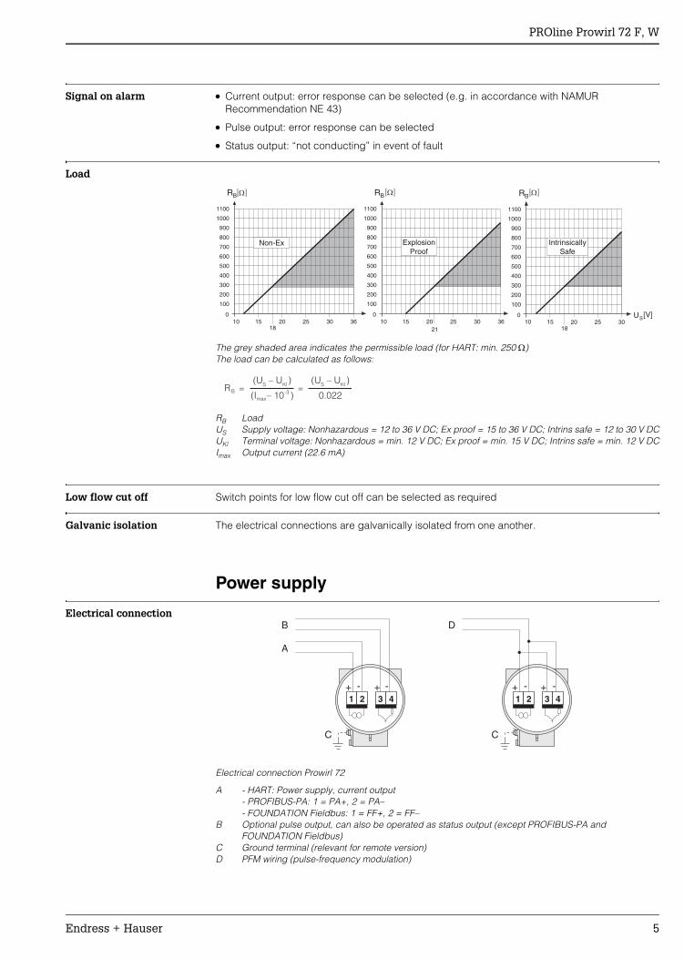
Signal on alarm • Current output: error response can be selected (e.g. in accordance with NAMUR Recommendation NE 43)
• Pulse output: error response can be selected
• Status output: “not conducting” in event of fault
Load
The grey shaded area indicates the permissible load (for HART: min. 250 Ω)The load can be calculated as follows:
RB LoadUS Supply voltage: Nonhazardous = 12 to 36 V DC; Ex proof = 15 to 36 V DC; Intrins safe = 12 to 30 V DCUKl Terminal voltage: Nonhazardous = min. 12 V DC; Ex proof = min. 15 V DC; Intrins safe = min. 12 V DCImax Output current (22.6 mA)
Low flow cut off Switch points for low flow cut off can be selected as required
Galvanic isolation The electrical connections are galvanically isolated from one another.
Power supply
Electrical connection
Electrical connection Prowirl 72
A - HART: Power supply, current output- PROFIBUS-PA: 1 = PA+, 2 = PA–- FOUNDATION Fieldbus: 1 = FF+, 2 = FF–
B Optional pulse output, can also be operated as status output (except PROFIBUS-PA and FOUNDATION Fieldbus)
C Ground terminal (relevant for remote version)D PFM wiring (pulse-frequency modulation)
0 0
100 100
200 200
300 300
400 400
500 500
600 600
700 700
800 800
900 900
1000 1000
1100 1100
B BR R
10 1020 2025 2530 3036 3615 1518 21
0
100
200
300
400
500
600
700
800
900
1000
1100
B
S
R
U [V]10 20 25 3015
18
IntrinsicallySafe
[ ]W [ ]W [ ]W
Non-Ex ExplosionProof
RB =S
(U – U )Kl
max(I – 10 )-3
0.022=
S(U – U )
Kl
1 2 1 23 4 3 4
A
D
C
+ ++ +- -- -
C
B
PROline Prowirl 72 F, W
6 Endress + Hauser
Supply voltage Nonhazardous: 12 to 36 V DC (with HART 18 to 36 V DC)Intrinsically safe: 12 to 30 V DC (with HART 18 to 30 V DC)Explosion proof: 15 to 36 V DC (with HART 21 to 36 V DC)
PROFIBUS-PA and FOUNDATION FieldbusNonhazardous: 9 to 32 V DCIntrinsically safe: 9 to 24 V DCExplosion proof: 9 to 32 V DCCurrent consumption → PROFIBUS-PA: 16 mA, FOUNDATION Fieldbus: 16 mA
Cable entry Power supply and signal cables (outputs):• Cable entry M20 x 1.5 (8 to 11.5 mm)• Thread for cable entry: ½" NPT, G ½" (not for remote version)• Fieldbus connector
Power supply failure • Totalizer stops at the last value determined (can be configured)• All settings are kept in the EEPROM• Error messages (incl. value of operated hours counter) are stored
Performance characteristics
Reference operating conditions
Error limits following ISO/DIN 11631:60° to 86°F (20 to 30°C), 30 to 60 psi (2 to 4 bar), Calibration rig traceable to national standardsCalibration with the corresponding process connection of the respective norms
Maximum measured error • Liquid:< 0.75% o.r. for Re > 20,000< 0.75% o.f.s for Re between 4000 to 20,000
• Gas/steam:< 1% o.r. for Re > 20,000< 1% o.f.s for Re between 4000 to 20,000
o.r. = Of reading, o.f.s = Of full scale, Re = Reynolds number
Repeatability ±0.25% o.r. (of reading)
Operating conditions: installation
Installation instructions Vortex meters require a fully developed flow profile as a prerequisite for correct volume flow measurement. For this reason, please note the following points when installing the device:
Orientation
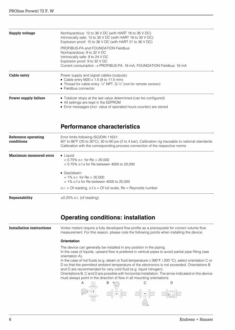
The device can generally be installed in any position in the piping. In the case of liquids, upward flow is prefered in vertical pipes to avoid partial pipe filling (see orientation A). In the case of hot fluids (e.g. steam or fluid temperature ≥ 390°F / 200 °C), select orientation C or D so that the permitted ambient temperature of the electronics is not exceeded. Orientations B and D are recommended for very cold fluid (e.g. liquid nitrogen).Orientations B, C and D are possible with horizontal installation. The arrow indicated on the device must always point in the direction of flow in all mounting orientations.
DA CBEsc
E- +
Esc
E- +
Esc
E- +
PROline Prowirl 72 F, W
Endress + Hauser 7
Caution! • If fluid temperature is ≥ 390°F (200 °C), orientation B is not permitted for the wafer version
(Prowirl 72 W) with a nominal diameter of 4” and 6” (DN 100 and DN 150).• In case of vertical orientation and downward flowing liquid, the piping has always to be
completely filled.
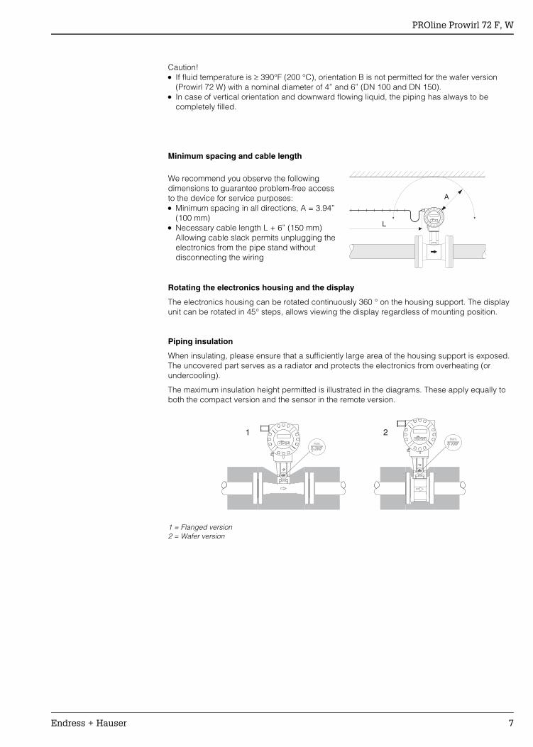
Minimum spacing and cable length
Rotating the electronics housing and the display
The electronics housing can be rotated continuously 360 ° on the housing support. The display unit can be rotated in 45° steps, allows viewing the display regardless of mounting position.
Piping insulation
When insulating, please ensure that a sufficiently large area of the housing support is exposed. The uncovered part serves as a radiator and protects the electronics from overheating (or undercooling).
The maximum insulation height permitted is illustrated in the diagrams. These apply equally to both the compact version and the sensor in the remote version.
1 = Flanged version2 = Wafer version
We recommend you observe the following dimensions to guarantee problem-free access to the device for service purposes: • Minimum spacing in all directions, A = 3.94”
(100 mm)• Necessary cable length L + 6” (150 mm)
Allowing cable slack permits unplugging the electronics from the pipe stand without disconnecting the wiring
L
A
Esc
E- +
1 2Esc
E- +
Esc
E- +
PROline Prowirl 72 F, W
8 Endress + Hauser
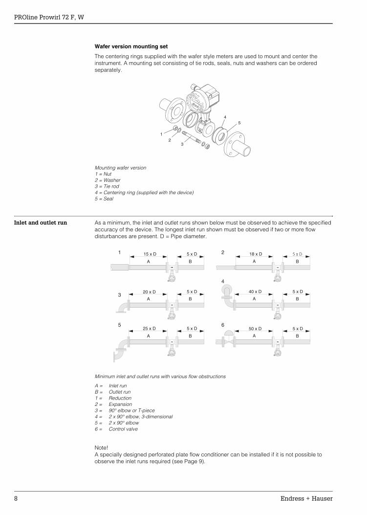
Wafer version mounting set
The centering rings supplied with the wafer style meters are used to mount and center the instrument. A mounting set consisting of tie rods, seals, nuts and washers can be ordered separately.
Mounting wafer version1 = Nut2 = Washer3 = Tie rod4 = Centering ring (supplied with the device)5 = Seal
Inlet and outlet run As a minimum, the inlet and outlet runs shown below must be observed to achieve the specified accuracy of the device. The longest inlet run shown must be observed if two or more flow disturbances are present. D = Pipe diameter.
Minimum inlet and outlet runs with various flow obstructions
A = Inlet runB = Outlet run1 = Reduction2 = Expansion3 = 90° elbow or T-piece4 = 2 x 90° elbow, 3-dimensional5 = 2 x 90° elbow6 = Control valve
Note! A specially designed perforated plate flow conditioner can be installed if it is not possible to observe the inlet runs required (see Page 9).
12
3
45
Esc
E- +
Esc
E- +Esc
E- +
Esc
E- +
15 x D 5 x D
A
1
3
5
2
4
6
A
A
A
A
A
B
B
B
B
B
B
18 x D 5 x D
20 x D 5 x D 40 x D 5 x D
25 x D 5 x D 50 x D 5 x D
Esc
E- +
Esc
E- +
PROline Prowirl 72 F, W
Endress + Hauser 9
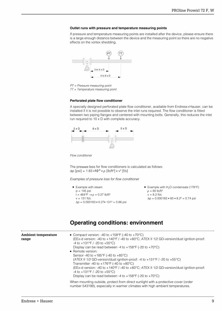
Outlet runs with pressure and temperature measuring points
If pressure and temperature measuring points are installed after the device, please ensure there is a large enough distance between the device and the measuring point so there are no negative effects on the vortex shedding.
PT = Pressure measuring pointTT = Temperature measuring point
Perforated plate flow conditioner
A specially designed perforated plate flow conditioner, available from Endress+Hauser, can be installed if it is not possible to observe the inlet runs required. The flow conditioner is fitted between two piping flanges and centered with mounting bolts. Generally, this reduces the inlet run required to 10 x D with complete accuracy.
Flow conditioner
The pressure loss for flow conditioners is calculated as follows:∆p [psi] = 1.83 •10-4 • ρ [lb/ft³] • v² [f/s]
Examples of pressure loss for flow conditioner
Operating conditions: environment
Ambient temperature range
• Compact version: -40 to +158°F (-40 to +70°C) (EEx-d version: -40 to +140°F / -40 to +60°C; ATEX II 1/2 GD-version/dust ignition-proof:-4 to +131°F / -20 to +55°C)Display can be read between -4 to +158°F (-20 to +70°C)
• Remote version:Sensor -40 to +185°F (-40 to +85°C)(ATEX II 1/2 GD-version/dust ignition-proof: -4 to +131°F / -20 to +55°C)Transmitter -40 to +176°F (-40 to +80°C) (EEx-d version: -40 to +140°F / -40 to +60°C; ATEX II 1/2 GD-version/dust ignition-proof:-4 to +131°F / -20 to +55°C)Display can be read between -4 to +158°F (-20 to +70°C)
When mounting outside, protect from direct sunlight with a protective cover (order number 543199), especially in warmer climates with high ambient temperatures.
PT TT
3 to 5 x D
4 to 8 x D
Esc
E- +
8 x D2 x D 5 x D
Esc
E- +
• Example with steamp = 145 psit = 464°F → ρ = 0.27 lb/ft³v = 131 ft/s∆p = 0.000183 • 0.27• 131² = 0.86 psi
• Example with H2O condensate (176°F)ρ = 60 lb/ft³v = 8.2 ft/s∆p = 0.000183 • 60 • 8.2² = 0.74 psi
PROline Prowirl 72 F, W
10 Endress + Hauser
Storage temperature -40 to +176°F (-40 to +80°C)(ATEX II 1/2 GD-version/dust ignition-proof: -4 to +131°F / -20 to +55°C)
Degree of protection NEMA 4X (IP 67) according to EN 60529
Vibration resistance Acceleration up to 1 g, 10 to 500 Hz, following IEC 60068-2-6
Electromagnetic compatibility (EMC)
According to EN 61326/A1 and NAMUR Recommendation NE 21.
Operating conditions: process
Medium temperature range
• DSC sensor (differential switched capacitor) capacitive sensor:
• Seal:
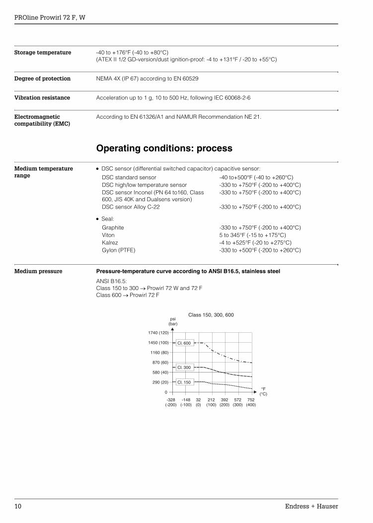
Medium pressure Pressure-temperature curve according to ANSI B16.5, stainless steel
ANSI B16.5:Class 150 to 300 → Prowirl 72 W and 72 FClass 600 → Prowirl 72 F
DSC standard sensor -40 to+500°F (-40 to +260°C)DSC high/low temperature sensor -330 to +750°F (-200 to +400°C)DSC sensor Inconel (PN 64 to160, Class 600, JIS 40K and Dualsens version)
-330 to +750°F (-200 to +400°C)
DSC sensor Alloy C-22 -330 to +750°F (-200 to +400°C)
Graphite -330 to +750°F (-200 to +400°C)Viton 5 to 345°F (-15 to +175°C)Kalrez -4 to +525°F (-20 to +275°C)Gylon (PTFE) -330 to +500°F (-200 to +260°C)
-328(-200)
-148(-100)
0
290 (20)
580 (40)
870 (60)
1160 (80)
1450 (100)
1740 (120)
32(0)
212(100)
392(200)
572(300)
752(400)
°F(°C)
psi(bar)
Class 150, 300, 600
Cl. 150
Cl. 300
Cl. 600
PROline Prowirl 72 F, W
Endress + Hauser 11
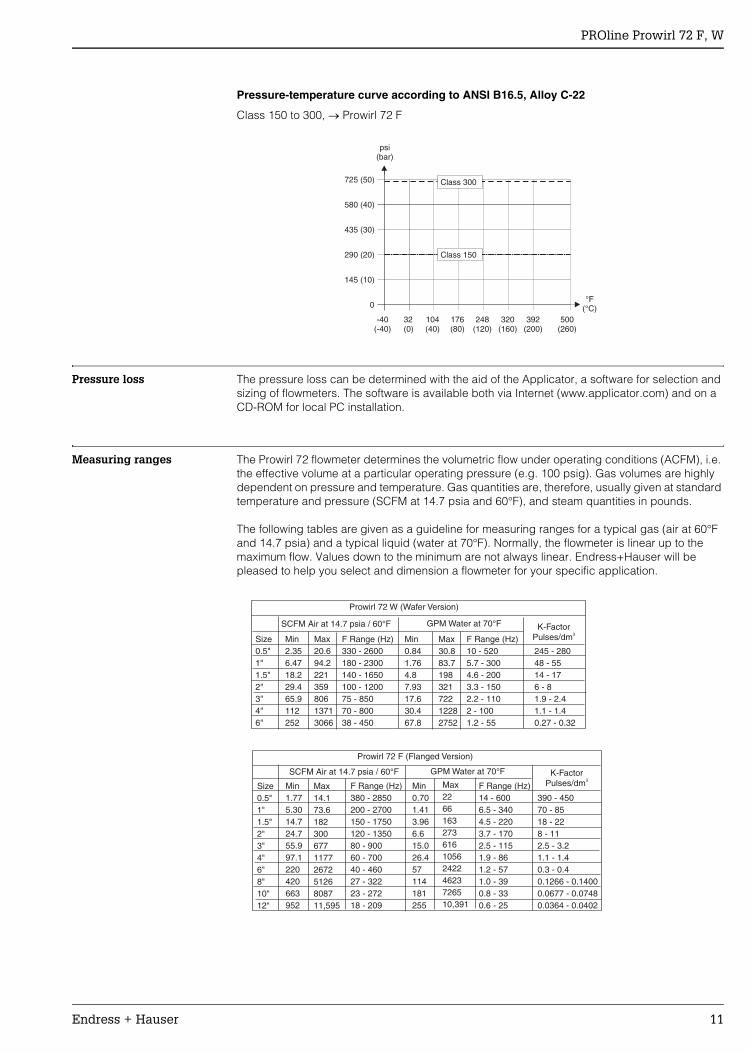
Pressure-temperature curve according to ANSI B16.5, Alloy C-22
Class 150 to 300, → Prowirl 72 F
Pressure loss The pressure loss can be determined with the aid of the Applicator, a software for selection and sizing of flowmeters. The software is available both via Internet (www.applicator.com) and on a CD-ROM for local PC installation.
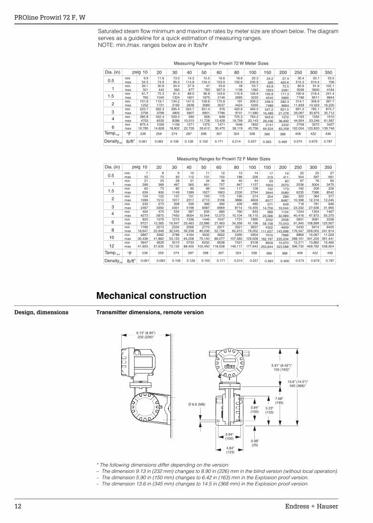
Measuring ranges The Prowirl 72 flowmeter determines the volumetric flow under operating conditions (ACFM), i.e. the effective volume at a particular operating pressure (e.g. 100 psig). Gas volumes are highly dependent on pressure and temperature. Gas quantities are, therefore, usually given at standard temperature and pressure (SCFM at 14.7 psia and 60°F), and steam quantities in pounds.
The following tables are given as a guideline for measuring ranges for a typical gas (air at 60°F and 14.7 psia) and a typical liquid (water at 70°F). Normally, the flowmeter is linear up to the maximum flow. Values down to the minimum are not always linear. Endress+Hauser will be pleased to help you select and dimension a flowmeter for your specific application.
-40(-40)
32(0)
0
145 (10)
290 (20)
435 (30)
580 (40)
725 (50)
104(40)
176(80)
248(120)
320(160)
392(200)
500(260)
°F(°C)
psi(bar)
Class 150
Class 300
Prowirl 72 W (Wafer Version)
SCFM Air at 14.7 psia / 60°F
SCFM Air at 14.7 psia / 60°F
GPM Water at 70°F
GPM Water at 70°F
K-FactorPulses/dm3
K-FactorPulses/dm3
Size0.5"1"1.5"2"3"4"6"
Size0.5"1"1.5"2"3"4"6"8"10"12"
Min2.356.4718.229.465.9112252
Min1.775.3014.724.755.997.1220420663952
Min0.841.764.87.9317.630.467.8
Min0.701.413.966.615.026.457114181255
Max20.694.222135980613713066
F Range (Hz)330 - 2600180 - 2300140 - 1650100 - 120075 - 85070 - 80038 - 450
F Range (Hz)380 - 2850200 - 2700150 - 1750120 - 135080 - 90060 - 70040 - 46027 - 32223 - 27218 - 209
F Range (Hz)14 - 6006.5 - 3404.5 - 2203.7 - 1702.5 - 1151.9 - 861.2 - 571.0 - 390.8 - 330.6 - 25
F Range (Hz)10 - 5205.7 - 3004.6 - 2003.3 - 1502.2 - 1102 - 1001.2 - 55
Max14.173.6182300677117726725126808711,595
Max30.883.719832172212282752
245 - 28048 - 5514 - 176 - 81.9 - 2.41.1 - 1.40.27 - 0.32
390 - 45070 - 8518 - 228 - 112.5 - 3.21.1 - 1.40.3 - 0.40.1266 - 0.14000.0677 - 0.07480.0364 - 0.0402
Max2266163273616105624224623726510,391
Prowirl 72 F (Flanged Version)
PROline Prowirl 72 F, W
12 Endress + Hauser
Mechanical construction
Design, dimensions Transmitter dimensions, remote version
* The following dimensions differ depending on the version:– The dimension 9.13 in (232 mm) changes to 8.90 in (226) mm in the blind version (without local operation).– The dimension 5.90 in (150 mm) changes to 6.42 in (163) mm in the Explosion proof version.– The dimension 13.6 in (345 mm) changes to 14.5 in (368 mm) in the Explosion proof version.
4.84”(123)
5.23”(133)
7.68”(195)
5.91” (6.42”)*150 (163)*
13.6” (14.5”)*345 (368)*
3.94”(100)
3.94”(100)
0.98”(25)
Ø 8.6 (M8)
9.13” (8.90”)232 (226)*
-
Saturated steam flow minimum and maximum rates by meter size are shown below. The diagram serves as a guideline for a quick estimation of measuring ranges.NOTE: min./max. ranges below are in lbs/hr
Measuring Ranges for Prowirl 72 W Meter Sizes
Measuring Ranges for Prowirl 72 F Meter Sizes
minmaxminmaxminmaxminmaxminmaxminmaxminmax
10psig 20 30 40 50 60 80 100 150 200 250 300 3509.9
54.526.132161.7760
101.61252223.72756385.84753875.4
10,785
11.674.930.644272.31045119.11721262.33789452.465351026
14,828
13.095.034.456081.41324134.22182295.44805509.482861156
18,802
14.3114.8
37.967789.51601147.52638324.75807
56010,015
127122,726
15.5134.4
4179396.91875159.63089351.46801
60611,728
137526,612
16.6153.9
43.8907.9103.62146170.83537
3767786
64813,428
147130,470
18.6192.6
491136115.92685
1914424420.69741725.3
16,7991646
38,119
20.3230.9
53.71362126.93220209.25305460.5
11,680794.2
20,1431802
45,706
24.232663.81923150.84545248.57489547.2
16,489943.6
28,4362141
64,524
27.4420.6
72.52481171.35865282.39664621.5
21,2761072
36,6922432
83,258
30.4515.3
80.63039190.67186314.1
11,839691.5
26,0671193
44,9542706
102,004
33.1610.4
91.63600216.48511356.6
14,023785.1
30,8751354
53,2463072
120,820
33.5706
102.14164
241.49844
397.716,220
875.735,712
151061,587
3427139,746
239
0.061
259
0.083
274
0.106
287
0.128
298
0.150
307
0.171
324
0.214
338
0.257
366
0.363
388
0.469
406
0.574
422
0.679
436
0.787
°F
6
4
3
2
1.5
1
0.5
Dia. (in)
Temp.sat
Densitysat lb/ft3
minmaxminmaxminmaxminmaxminmaxminmaxminmaxminmaxminmaxminmax
10psig 20 30 40 50 60 80 100 150 200 250 300 3507
5321
26862
659104
1099233
2467404
4273920
97211766
18,6472867
30,4363947
41,903
87325
36873
906122
1512273
3392474
58751079
13,3652073
25,6483362
41,8624629
57,635
99328
46782
1149137
1917308
4301534
74501215
16,9472334
32,5453788
53,1205215
73,135
10112
31565
901389
1512317
3395198
58790041336
20,4832566
39,3384164
64,2085733
88,400
11131
34661
981627
1632713
3666087
63510.544
144623,986
277546,036
450575,140
6202103,450
12150
36757104
1863175
3106392
6969680
12,0731547
27,4632971
52,7364822
86,0776638
118,508
13188
40947117
2330195
3886439
8714760
15,1041731
34,3583321
65,9135390
107,5837421
148,117
14226
441137
1282794
2144659
48010,455
83318,110
189541,196
363779,052
5904129,028
8128177,643
17319
531604
1523944
2546577
57114,759
98925,566
225258,158
4322111,627
7015182,197
9659250,844
19411
602070
1735089
2898487
64919,044
112432,989
255875,043
4909143,998
7968235,034
10,970323,588
22504
672536
1926235
32010,398
71823,332
124440,416
283191,940
5435176,547
8869288,161
12,211396,732
25597
763004
2097386
38412,316
78127,636
135447,872
3081108,899
5914209,055
10,067341,220
13,862469,782
27691
853475
2268542
37712,245
84631,965
146755,370
3336125,957
6405241,814
11,229391,441
15,460538,924
239
0.061
259
0.083
274
0.106
287
0.128
298
0.150
307
0.171
324
0.214
338
0.257
366
0.363
388
0.469
406
0.574
422
0.679
436
0.787
°F
6
8
10
12
4
3
2
1.5
1
0.5
Dia. (in)
Temp.sat
Densitysat lb/ft3
PROline Prowirl 72 F, W
Endress + Hauser 13
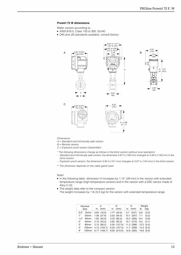
Prowirl 72 W dimensions
Wafer version according to:• ANSI B16.5, Class 150 to 300, Sch40• DIN and JIS standards available, consult factory
Dimensions:A = Standard and Intrinsically safe versionB = Remote versionC = Explosion proof version (transmitter)
* The following dimensions change as follows in the blind version (without local operation):– Standard and Intrinsically safe version: the dimension 5.87 in (149 mm) changes to 5.59 in (142) mm in the
blind version.– Explosion proof version: the dimension 5.94 in (151 mm) changes to 5.67 in (144 mm) in the blind version.
** The dimension depends on the cable gland used.
Note! • In the following table, dimension H increases by 1.14” (29 mm) in the version with extended
temperature range (high temperature version) and in the version with a DSC sensor made of Alloy C-22.
• The weight data refer to the compact version. The weight increases by 1 lb (0.5 kg) for the version with extended temperature range.
2.56”(65)
2.56”(65)
d
D
H - 1.67”(H - 42.5)
3.74”(95)
BA
H
4.76”(121)
5.55” to 5.94”**(141 to 151)**
6.34” to 7.13” **(161 to 181)**
Esc
E- +
5.87” (5.59”)*149 (142)*
C
Esc
E- +
H + 0.28”(H + 7)
6.34”(161)
INEXPLOSIVEATMOSPHERE
KEEPH
TIGHTWENCIRCUIT ALIVE
WARNING
NICHT UNTER SPANNUNG ÖFFNEN
AVERTISSEMENTNE
S
PAS OUVRIR OUS TENSIONWARNUNG
5.94” (5.67”)*151 (144)*
4.52”(115)
0.5" 15mm1" 25mm1.5" 40mm2" 50mm3" 80mm4" 100mm6" 150mm
1.77 (45.0)2.52 (64.0)3.23 (82.0)3.62 (92.0)5.00 (127.0)6.20 (157.2)8.50 (215.9)
0.65 (16.5)1.08 (27.6)1.65 (42.0)2.10 (53.5)3.15 (80.2)4.12 (104.7)6.17 (156.7)
9.7 (247)10.1 (257)10.4 (265)10.7 (272)11.2 (286)11.7 (299)12.8 (325)
6.6 (3.0)7.1 (3.2)8.4 (3.8)9.0 (4.1)12.2 (5.5)14.3 (6.5)19.8 (9.0)
din. (mm)
Din. (mm)
Hin. (mm)
Weightlb. (kg)
NominalSize
PROline Prowirl 72 F, W
14 Endress + Hauser
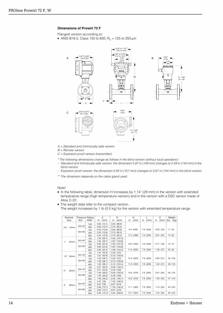
Dimensions of Prowirl 72 F
Flanged version according to:• ANSI B16.5, Class 150 to 600, Ra = 125 to 250 µin
A = Standard and Intrinsically safe versionB = Remote versionC = Explosion proof version (transmitter)
* The following dimensions change as follows in the blind version (without local operation):– Standard and Intrinsically safe version: the dimension 5.87 in (149 mm) changes to 5.59 in (142 mm) in the
blind version.– Explosion proof version: the dimension 5.94 in (151 mm) changes to 5.67 in (144 mm) in the blind version.
** The dimension depends on the cable gland used.
Note! • In the following table, dimension H increases by 1.14” (29 mm) in the version with extended
temperature range (high temperature version) and in the version with a DSC sensor made of Alloy C-22.
• The weight data refer to the compact version.The weight increases by 1 lb (0.5 kg) for the version with extended temperature range.
BA
C
H
LX
Esc
E- +
D
d
Esc
E- +
H + 0.28”(H + 7)
INEXPLOSIVEATMOSPHERE
KEEPH
TIGHTWENCIRCUIT ALIVE
WARNING
NICHT UNTER SPANNUNG ÖFFNEN
AVERTISSEMENTNE
S
PAS OUVRIR OUS TENSIONWARNUNG
H - 1.65”(H - 42)
3.74”(95)
4.52”(115)4.76”
(121)
5.55” to 5.94”**(141 to 151)**
6.34” to 7.13” **(161 to 181)**
5.87” (5.59”)*149 (142)*
6.34”(161)5.94” (5.67”)*
151 (144)*
0.5" 15mm
1" 25mm
1.5" 40mm
2" 50mm
3" 80mm
150300150300600150300150300600150300150300600150300150300600150300150300600
Sch 40
Sch 80
Sch 40
Sch 80
Sch 40
Sch 80
Sch 40
Sch 80
Sch 40
Sch 80
3.50 (88.9)3.74 (95.0)3.50 (88.9)3.74 (95.0)3.73 (95.3)4.25 (107.9)4.87 (123.8)4.25 (107.9)4.87 (123.8)4.88 (124.0)5.00 (127)6.13 (155.6)5.00 (127)6.13 (155.6)6.12 (155.4)6.00 (152.4)6.49 (165)6.00 (152.4)6.49 (165)6.50 (165.1)7.50 (190.5)8.27 (210)7.50 (190.5)8.27 (210)8.25 (209.6)
7.8 (200)
7.8 (200)
7.8 (200)
7.8 (200)
7.8 (200)
7.8 (200)
7.8 (200)
7.8 (200)
7.8 (200)
7.8 (200)
0.63 (16)
0.91 (23)
0.71 (18)
1.06 (27)
0.83 (21)
1.22 (31)
0.91 (23)
1.30 (33)
1.14 (29)
1.54 (39)
11 (5)
13 (6)
15 (7)
20 (9)
22 (10)
28 (13)
26 (12)
31 (14)
44 (20)
48 (22)
0.62 (15.7)0.62 (15.7)0.54 (13.9)0.54 (13.9)0.54 (13.9)1.05 (26.7)1.05 (26.7)0.95 (24.3)0.95 (24.3)0.95 (24.3)1.61 (40.9)1.61 (40.9)1.50 (38.1)1.50 (38.1)1.50 (38.1)2.07 (52.6)2.07 (52.6)1.94 (49.2)1.94 (49.2)1.94 (49.2)3.07 (78)3.07 (78)2.90 (73.7)2.90 (73.7)2.90 (73.7))
9.4 (248)
11.3 (288)
10.0 (255)
11.6 (295)
10.3 (263)
11.9 (303)
10.6 (270)
12.2 (310)
11.1 (283)
12.7 (323)
din. (mm)
Din. (mm)
Lin. (mm)
Xin. (mm)
Weightlbs (kg)
Hin. (mm)
NominalSize
Pressure RatingSch. ANSI
PROline Prowirl 72 F, W
Endress + Hauser 15
4" 100mm
6" 150mm
150300150300600150300150300600150300150300150300
Sch 40
Sch 80
Sch 40
Sch 80
9.00 (228.6)10.0 (254)9.00 (228.6)10.0 (254)10.7 (273.1)11.0 (279.4)12.5 (317.5)11.0 (279.4)12.5 (317.5)13.0 (355.6)13.5 (342.9)15.0 (381.0)16.0 (406.4)17.5 (444.5)19.0 (482.6)20.5 (520.7)
9.8 (250)
9.8 (250)
11.8 (300)
11.8 (300)
1.26 (32)
1.93 (49)
1.46 (37)
2.52 (64)
60 (27)
95 (43)
112 (51)
192 (87)
4.03 (102.4)4.03 (102.4)3.82 (97)3.82 (97)3.82 (97)6.07 (154.2)6.07 (154.2)5.76 (146.35.76 (146.3)5.76 (146.3)7.98 (202.7)7.98 (202.7)10.0 (254.5)10.0 (254.5)12.0 (304.812.0 (304.8)
11.6 (295)
13.2 (335)
12.5 (319)
14.1 (359)
din. (mm)
Din. (mm)
Lin. (mm)
Xin. (mm)
Weightlbs (kg)
Hin. (mm)
NominalSize
Pressure RatingSch. ANSI
141 (64)168 (76)203 (92)240 (109)315 (143)357 (162)
13.7 (348)
14.7 (375)
15.6 (398)
Sch 40
Sch 40
Sch 40
8" 200mm
10" 250mm
12" 300mm
11.8 (300)
14.9 (375)
17.7 (450)
1.65 (42)
1.89 (48)
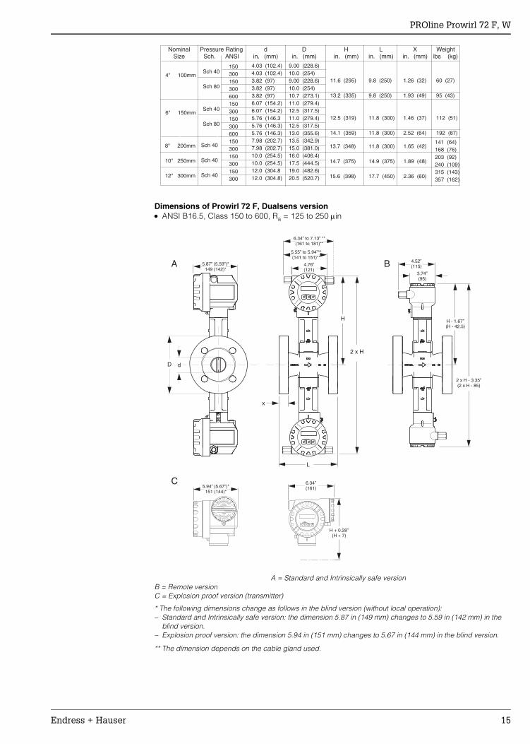
2.36 (60)
Dimensions of Prowirl 72 F, Dualsens version• ANSI B16.5, Class 150 to 600, Ra = 125 to 250 µin
dD
BA
H
2 x H
L
x
C
Esc
E- +
INEXPLOSIVEATMOSPHERE
KEEPH
TIGHTWENCIRCUIT ALIVE
WARNING
NIC
HT UNTER SPANNUNG ÖFFNEN
AVERTISSEMENTNE
S
PAS OUVRIR OUS TENSIONWARNUNG
Esc
E- +
Esc
E- +
H + 0.28”(H + 7)
3.74”(95)
4.52”(115)
H - 1.67”(H - 42.5)
2 x H - 3.35”(2 x H - 85)
4.76”(121)
5.55” to 5.94”**(141 to 151)**
6.34” to 7.13” **(161 to 181)**
5.87” (5.59”)*149 (142)*
6.34”(161)5.94” (5.67”)*
151 (144)*
A = Standard and Intrinsically safe versionB = Remote versionC = Explosion proof version (transmitter)
* The following dimensions change as follows in the blind version (without local operation):– Standard and Intrinsically safe version: the dimension 5.87 in (149 mm) changes to 5.59 in (142 mm) in the
blind version.– Explosion proof version: the dimension 5.94 in (151 mm) changes to 5.67 in (144 mm) in the blind version.
** The dimension depends on the cable gland used.
PROline Prowirl 72 F, W
16 Endress + Hauser
1.5" 40mm
2" 50mm
3" 80mm
4" 100mm
6" 150mm
150300150300600150300150300150300150300600150300150300600150300150300600
Sch 40
Sch 80
Sch 40
Sch 80
Sch 40
Sch 80
Sch 40
Sch 80
Sch 40
Sch 80
5.00 (127.0)6.13 (155.6)5.00 (127.0)6.13 (155.6)6.12 (155.4)6.00 (152.4)6.50 (165.0)6.00 (152.4)6.50 (165.0)7.50 (190.5)8.27 (210.0)7.50 (190.5)8.27 (210.0)8.25 (209.6)9.00 (228.6)10.0 (254.0)9.00 (228.6)10.0 (254.0)10.7 (273.1)11.0 (279.4)12.5 (317.5)11.0 (279.4)12.5 (317.5)14.0 (355.6)
7.8 (200)
7.8 (200)
7.8 (200)
9.8 (250)
11.8 (300)
1.22 (31)
1.30 (33)
1.54 (39)
1.93 (49)
2.52 (64)
35 (16)
40 (18)
55 (25)
93 (42)
176 (80)
1.61 (40.9)1.61 (40.9)1.50 (38.1)1.50 (38.1)1.50 (38.1)2.07 (56.6)2.07 (56.6)1.94 (49.2)1.94 (49.2)3.07 (78.0)3.07 (78.0)2.90 (73.7)2.90 (73.7)2.90 (73.7)4.03 (102.4)4.03 (102.4)3.82 (97.0)3.82 (97.0)3.82 (97.0)6.07 (154.2)6.07 (154.2)5.76 (146.3)5.76 (146.3)5.76 (146.3)
11.9 (303)
12.2 (310)
12.7 (323)
13.2 (335)
14.2 (359)
din. (mm)
Din. (mm)
Lin. (mm)
Xin. (mm)
Weightlbs (kg)
Hin. (mm)
NominalSize
Pressure RatingANSI Sch.
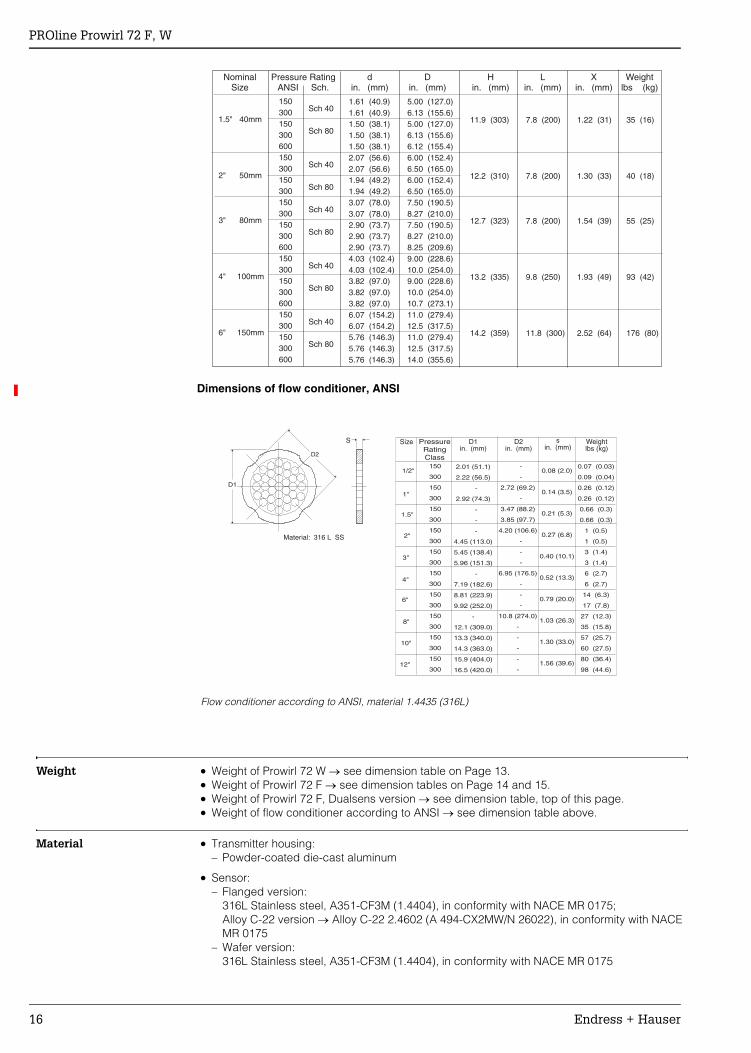
Dimensions of flow conditioner, ANSI
Flow conditioner according to ANSI, material 1.4435 (316L)
Weight • Weight of Prowirl 72 W → see dimension table on Page 13.• Weight of Prowirl 72 F → see dimension tables on Page 14 and 15.• Weight of Prowirl 72 F, Dualsens version → see dimension table, top of this page.• Weight of flow conditioner according to ANSI → see dimension table above.
Material • Transmitter housing:– Powder-coated die-cast aluminum
• Sensor:– Flanged version:
316L Stainless steel, A351-CF3M (1.4404), in conformity with NACE MR 0175;Alloy C-22 version → Alloy C-22 2.4602 (A 494-CX2MW/N 26022), in conformity with NACE MR 0175
– Wafer version:316L Stainless steel, A351-CF3M (1.4404), in conformity with NACE MR 0175
D1
S
D2
Size Weightlbs (kg)
sin. (mm)
D2in. (mm)
D1in. (mm)
1/2"
2"
6"
8"
10"
12"
1"
3"
1.5"
4"
Material: 316 L SS
150
300
150
300
150
300
150
300
150
300
150
300
150
300
150
300
150
300
150
300
2.01 (51.1)
2.22 (56.5)
-
2.92 (74.3)
-
-
-
4.45 (113.0)
5.45 (138.4)
5.96 (151.3)
-
7.19 (182.6)
8.81 (223.9)
9.92 (252.0)
-
12.1 (309.0)
13.3 (340.0)
14.3 (363.0)
15.9 (404.0)
16.5 (420.0)
-
-
2.72 (69.2)
-
3.47 (88.2)
3.85 (97.7)
4.20 (106.6)
-
-
-
6.95 (176.5)
-
-
-
10.8 (274.0)
-
-
-
-
-
0.07 (0.03)
0.09 (0.04)
0.26 (0.12)
0.26 (0.12)
0.66 (0.3)
0.66 (0.3)
1 (0.5)
1 (0.5)
3 (1.4)
3 (1.4)
6 (2.7)
6 (2.7)
14 (6.3)
17 (7.8)
27 (12.3)
35 (15.8)
57 (25.7)
60 (27.5)
80 (36.4)
98 (44.6)
0.08 (2.0)
0.14 (3.5)
0.21 (5.3)
0.27 (6.8)
0.40 (10.1)
0.52 (13.3)
0.79 (20.0)
1.03 (26.3)
1.30 (33.0)
1.56 (39.6)
PressureRatingClass
PROline Prowirl 72 F, W
Endress + Hauser 17
• Flanges:– EN (DIN) → 316L Stainless steel, A351-CF3M (1.4404), in conformity with NACE MR 0175
(DN 15 to150 with pressure rating up to PN 40: as of 2004 changeover from fully cast construction to construction with weld-on flanges in 1.4404)
– ANSI and JIS → 316L Stainless steel, A351-CF3M, in conformity with NACE MR 0175 ( ½" to 6" with pressure rating up to Cl 300 and DN 15 to 150 with pressure rating up to 20 K: as of 2004 changeover from fully cast construction to construction with weld-on flanges in 316/316L, in conformity with NACE MR 0175)
– Alloy C-22 version (EN/DIN/ANSI/JIS) → Alloy C-22 2.4602 (A 494-CX2MW/N 26022), in conformity with NACE MR 0175
• DSC sensor (differential switched capacitor; capacitive sensor)Wetted parts (marked as “wet” on the DSC sensor flange):– Standard for pressure ratings up to PN 40, Cl 300, JIS 40 K (apart from Dualsens version):
Stainless steel 1.4435 (317L), in conformity with NACE MR 0175– Higher pressure ratings and Dualsens version:
Inconel 2.4668/N 07718 (B637) (Inconel 718), in conformity with NACE MR 0175– Alloy C-22 sensor: Alloy C-22, 2.4602/N 06022, in conformity with NACE MR 0175
• Non-wetted parts:– 304 Stainless steel 1.4301 (CF3)
• Support:– 304L Stainless steel, 1.4308 (CF8)
• Seal:– Graphite (Grafoil)– Viton– Kalrez 6375– Gylon (PTFE) 3504
Human interface
Display elements Liquid crystal display, double-spaced, plain text display, 16 characters per lineDisplay can be configured individually, e.g. for measured variables and status values, totalizers
Operating elements(HART)
Local operation with three keys (O, S, F)Quick Setup for quick commissioningOperating elements accessible also in hazardous areas
Remote operation Remote operation possible via:
• HART• PROFIBUS-PA• FOUNDATION Fieldbus• Endress+Hauser Service Protocol
Certificates and approvals
CE mark The device is in conformity with the statutory requirements of the EC Directives. Endress+Hauser confirms successful testing of the device by affixing the CE mark.
Ex-approval • Intrinsically safe:– ATEX/CENELEC
II1/2G, EEx ia IIC T1 to T6 (T1 to T4 for PROFIBUS-PA and FOUNDATION Fieldbus)II1/2GD, EEx ia IIC T1 to T6 (T1 to T4 for PROFIBUS-PA and FOUNDATION Fieldbus)II1G, EEx ia IIC T1 to T6 (T1 to T4 for PROFIBUS-PA and FOUNDATION Fieldbus)II2G, EEx ia IIC T1 to T6 (T1 to T4 for PROFIBUS-PA and FOUNDATION Fieldbus)II3G, EEx nA IIC T1 to T6 X (T1 to T4 X for PROFIBUS-PA and FOUNDATION Fieldbus)
.
PROline Prowirl 72 F, W
18 Endress + Hauser
– FM ISClass I/II/III Div. 1/2, Group A to G
– CSAClass I/II/III Div. 1/2, Group A to GClass II Div. 1, Group E to GClass III
• Explosion proof:– ATEX/CENELEC
II1/2G, EEx d [ia] IIC T1 to T6 (T1 to T4 for PROFIBUS-PA and FOUNDATION Fieldbus)II1/2GD, EEx ia IIC T1 to T6 (T1 to T4 for PROFIBUS-PA and FOUNDATION Fieldbus)II2G, EEx d [ia] IIC T1 to T6 (T1 to T4 for PROFIBUS-PA and FOUNDATION Fieldbus)
– FMClass I/II/III Div. 1, Groups A to G
– CSAClass I/II/III Div. 1,2 Groups A to GClass II Div. 1, Groups E to GClass III
More information on the Ex-approvals can be found in the separate Ex-documentation.
Pressure measuring device approval
Devices with a nominal diameter smaller than or equal to 1” (DN 25) correspond to Article 3 (3) of the EC Directive 97/23/EC (Pressure Equipment Directive). For larger nominal diameters, certified flowmeters to Category III are optionally also available if necessary (depends on fluid and operating pressure). All devices are applicable for all fluids and instable gases on principle and have been designed and manufactured in accordance to sound engineering practice.
CertificationFOUNDATION Fieldbus
The flowmeter has successfully passed all test procedures and is certified and registered by the Fieldbus FOUNDATION. The device thus meets all the requirements of the specifications following:
• Certified according to FOUNDATION Fieldbus Specification• The device meets all the specifications of the FOUNDATION Fieldbus-H1• Interoperability Test Kit (ITK), revision status 4.5 (device certification no. available on request):
The device can also be operated with certified devices of other manufacturers• Physical Layer Conformance Test of the Fieldbus FOUNDATION
Certification PROFIBUS-PA
The flowmeter has successfully passed all test procedures and is certified and registered by the PNO (PROFIBUS User Organization). The device thus meets all the requirements of the specifications following:
• Certified according to PROFIBUS-PA profile version 3.0 (device certification number available on request)
• The device can also be operated with certified devices of other manufacturers (interoperability)
Other standards and guidelines
• EN 60529: Degrees of protection by housing (IP code).• EN 61010: Protection measures for electrical equipment for measurement, control, regulation
and laboratory procedures.• EN 61326/A1: Electromagnetic compatibility (EMC requirements).• NAMUR NE 21: Electromagnetic compatibility (EMC) of industrial process and laboratory
control equipment.• NAMUR NE 43: Standardization of the signal level for the breakdown information of digital
transmitters with analog output signal.• NACE Standard MR0175: Standard Material Requirements - Sulfide Stress Cracking Resistant
Metallic Materials for Oilfield Equipment.• VDI 2643: Measurement of fluid flow by means of vortex flowmeters.
• ANSI/ISA-S82.01: Safety Standard for Electrical and Electronic Test, Measuring, Controlling and related Equipment - General Requirements. Pollution degree 2, Installation Category II
• CAN/CSA-C22.2 No. 1010.1-92: Safety Standard for Electrical Equipment for Measurement and Control and Labatory Use. Pollution degree 2, Installation Category II
PROline Prowirl 72 F, W
Endress + Hauser 19
Accessories• Wafer version mounting set• Spare parts as per separate price list• Replacement transmitter Prowirl 72• Universal flow and energy computer RMC 621• Steam computer RMS-621• Compart DXF 351 flow computer• Flow conditioner• HART Communicator DXR 275 handheld terminal• HART Communicator DXR 375 handheld terminal• Active barrier preline RN 221 N• Pressure transducer Cerabar T resp. Cerabar S (PROFIBUS-PA, FOUNDATION Fieldbus)• Thermoresistance Omnigrad TR 10• Process display RIA 250, RIA 251• Field display RIA 261 resp. RID 261 (PROFIBUS-PA)• Applicator• ToF Tool - FieldTool Package• Fieldgate FXA 520
Documentation• Operating Instructions PROline Prowirl 72• Operating Instructions PROline Prowirl 72 PROFIBUS-PA• Operating Instructions PROline Prowirl 72 FOUNDATION Fieldbus• Related Ex-documentation• System Information PROline Prowirl 72• System Information PROline Prowirl 72/73• Related documentation for Pressure Equipment Directive
Additional ordering information for Prowirl 72You can order Prowirl 72 with pre-programming of the most important parameters. For this purpose the following information is required when ordering the device:• 20 mA value = measured value (e.g. 1000 kg/h) that shall result in a current of 20 mA• Pulse value (if the device is ordered with a pulse output)
If you want to display the flow in mass units, please indicate in addition:• the mean operation density of your media including units
If you want to display the flow in corrected volume flow units, please indicate in addition:• the operation and the reference density of your media including units
You can reset the device to this ordered state later on.
PROline Prowirl 72 F, W
20 Endress + Hauser
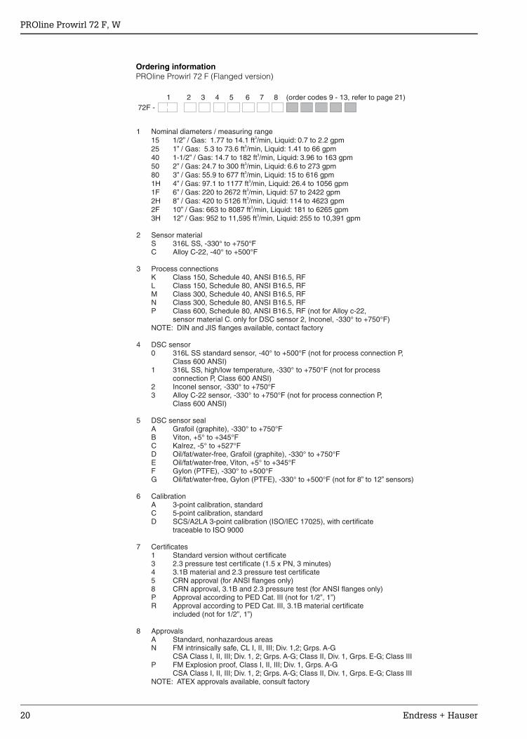
72F -
1 Nominal diameters / measuring range15 1/2” / Gas: 1.77 to 14.1 ft /min, Liquid: 0.7 to 2.2 gpm3
25 1” / Gas: 5.3 to 73.6 ft /min, Liquid: 1.41 to 66 gpm40 1-1/2” / Gas: 14.7 to 182 ft /min, Liquid: 3.96 to 163 gpm50 2” / Gas: 24.7 to 300 ft /min, Liquid: 6.6 to 273 gpm80 3” / Gas: 55.9 to 677 ft /min, Liquid: 15 to 616 gpm1H 4” / Gas: 97.1 to 1177 ft /min, Liquid: 26.4 to 1056 gpm1F 6” / Gas: 220 to 2672 ft /min, Liquid: 57 to 2422 gpm2H 8” / Gas: 420 to 5126 ft /min, Liquid: 114 to 4623 gpm2F 10” / Gas: 663 to 8087 ft /min, Liquid: 181 to 6265 gpm3H 12” / Gas: 952 to 11,595 ft /min, Liquid: 255 to 10,391 gpm
2 Sensor materialS 316L SS, -330° to +750°FC Alloy C-22, -40° to +500°F
3 Process connectionsK Class 150, Schedule 40, ANSI B16.5, RFL Class 150, Schedule 80, ANSI B16.5, RFM Class 300, Schedule 40, ANSI B16.5, RFN Class 300, Schedule 80, ANSI B16.5, RFP Class 600, Schedule 80, ANSI B16.5, RF (not for Alloy c-22,
sensor material C. only for DSC sensor 2, Inconel, -330° to +750°F)NOTE: DIN and JIS flanges available, contact factory
4 DSC sensor0 316L SS standard sensor, -40° to +500°F (not for process connection P,
Class 600 ANSI)1 316L SS, high/low temperature, -330° to +750°F (not for process
connection P, Class 600 ANSI)2 Inconel sensor, -330° to +750°F3 Alloy C-22 sensor, -330° to +750°F (not for process connection P,
Class 600 ANSI)
5 DSC sensor sealA Grafoil (graphite), -330° to +750°FB Viton, +5° to +345°FC Kalrez, -5° to +527°FD Oil/fat/water-free, Grafoil (graphite), -330° to +750°FE Oil/fat/water-free, Viton, +5° to +345°FF Gylon (PTFE), -330° to +500°FG Oil/fat/water-free, Gylon (PTFE), -330° to +500°F (not for 8” to 12” sensors)
6 CalibrationA 3-point calibration, standardC 5-point calibration, standardD SCS/A2LA 3-point calibration (ISO/IEC 17025), with certificate
traceable to ISO 9000
7 Certificates1 Standard version without certificate3 2.3 pressure test certificate (1.5 x PN, 3 minutes)4 3.1B material and 2.3 pressure test certificate5 CRN approval (for ANSI flanges only)8 CRN approval, 3.1B and 2.3 pressure test (for ANSI flanges only)P Approval according to PED Cat. III (not for 1/2”, 1”)R Approval according to PED Cat. III, 3.1B material certificate
included (not for 1/2”, 1”)
8 ApprovalsA Standard, nonhazardous areasN FM intrinsically safe, CL I, II, III; Div. 1,2; Grps. A-G
CSA Class I, II, III; Div. 1, 2; Grps. A-G; Class II, Div. 1, Grps. E-G; Class IIIP FM Explosion proof, Class I, II, III; Div. 1, Grps. A-G
CSA Class I, II, III; Div. 1, 2; Grps. A-G; Class II, Div. 1, Grps. E-G; Class IIINOTE: ATEX approvals available, consult factory
3
3
3
3
3
3
3
3
3
1 2 3 4 5 6 7 8 (order codes 9 - 13, refer to page 21)
Ordering informationPROline Prowirl 72 F (Flanged version)
PROline Prowirl 72 F, W
Endress + Hauser 21
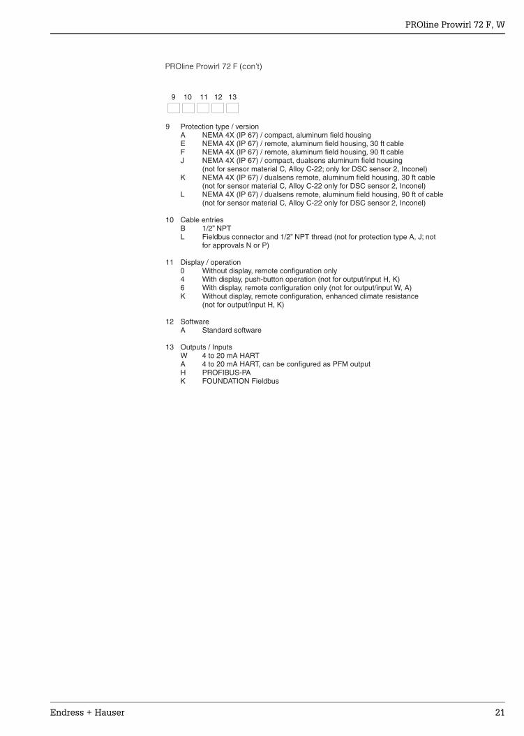
PROline Prowirl 72 F (con’t)
9 Protection type / versionA NEMA 4X (IP 67) / compact, aluminum field housingE NEMA 4X (IP 67) / remote, aluminum field housing, 30 ft cableF NEMA 4X (IP 67) / remote, aluminum field housing, 90 ft cableJ NEMA 4X (IP 67) / compact, dualsens aluminum field housing
(not for sensor material C, Alloy C-22; only for DSC sensor 2, Inconel)K NEMA 4X (IP 67) / dualsens remote, aluminum field housing, 30 ft cable
(not for sensor material C, Alloy C-22 only for DSC sensor 2, Inconel)L NEMA 4X (IP 67) / dualsens remote, aluminum field housing, 90 ft of cable
(not for sensor material C, Alloy C-22 only for DSC sensor 2, Inconel)
10 Cable entriesB 1/2” NPTL Fieldbus connector and 1/2” NPT thread (not for protection type A, J; not
for approvals N or P)
11 Display / operation0 Without display, remote configuration only4 With display, push-button operation (not for output/input H, K)6 With display, remote configuration only (not for output/input W, A)K Without display, remote configuration, enhanced climate resistance
(not for output/input H, K)
12 SoftwareA Standard software
13 Outputs / InputsW 4 to 20 mA HARTA 4 to 20 mA HART, can be configured as PFM outputH PROFIBUS-PAK FOUNDATION Fieldbus
9 10 11 12 13
PROline Prowirl 72 F, W
22 Endress + Hauser
Ordering informationPROline Prowirl 72 W (Wafer version)
72W -
1 Nominal diameters / measuring range15 1/2” / Gas: 2.35 to 20.6 ft /min, Liquid: 0.84 to 30.8 gpm3
25 1” / Gas: 6.47 to 94.2 ft /min, Liquid: 1.76 to 83.7 gpm40 1-1/2” / Gas: 18.2 to 221 ft /min, Liquid: 4.8 to 198 gpm50 2” / Gas: 29.4 to 359 ft /min, Liquid: 7.93 to 321 gpm80 3” / Gas: 65.9 to 806 ft /min, Liquid: 17.6 to 722 gpm1H 4” / Gas: 112 to 1371 ft /min, Liquid: 30.4 to 1228 gpm1F 6” / Gas: 252 to 3066 ft /min, Liquid: 67.8 to 2752 gpm
2 Sensor materialS 316L SS
3 Process connectionsK Class 150, Schedule 40, ANSI B16.5, RFM Class 300, Schedule 40, ANSI B16.5, RFNOTE: DIN and JIS flanges available, contact factory
4 DSC sensor0 316L SS standard version, -40° to +500°F1 316L SS high/low temperature, -330° to +750°F3 Alloy C-22, -330° to +750°F4 316L with thermometer, -330° to +750°F
5 DSC sensor sealA Grafoil (graphite), -330° to +750°FB Viton, +5° to +345°FC Kalrez, -5° to +527°FD Oil/fat/water-free, Grafoil (graphite), -330° to +750°FE Oil/fat/water-free, Viton, +5° to +345°FF Gylon (PTFE), -330° to +500°FG Oil/fat/water-free, Gylon (PTFE), -330° to +500°F (not for 8” to 12” sensors)
6 CalibrationA 3-point calibration, standardC 5-point calibration, standardD SCS/A2LA 3-point calibration (ISO/IEC 17025), with certificate
traceable to ISO 9000
7 Certificates1 Standard version without certificate3 2.3 pressure test certificate (1.5 x PN, 3 minutes)4 3.1B material and 2.3 pressure test certificate5 CRN approval (for ANSI flanges only)8 CRN approval, 3.1B and 2.3 pressure test (for ANSI flanges only)P Approval according to PED Cat. III (not for 1/2”, 1”)R Approval according to PED Cat. III, 3.1B material certificate
included (not for 1/2”, 1”)
8 ApprovalsA Standard, nonhazardous areasN FM intrinsically safe, CL I, II, III; Div. 1,2; Grps. A-G
CSA Class I, II, III; Div. 1, 2; Grps. A-G; Class II, Div. 1, Grps. E-G; Class IIIP FM Explosion proof, Class I, II, III; Div. 1, Grps. A-G
CSA Class I, II, III; Div. 1, 2; Grps. A-G; Class II, Div. 1, Grps. E-G; Class IIINOTE: ATEX approvals available, consult factory
9 Protection type / versionA NEMA 4X (IP 67) / compact, aluminum field housingE NEMA 4X (IP 67) / remote, aluminum field housing, 30 ft cableF NEMA 4X (IP 67) / remote, aluminum field housing, 90 ft cable
3
3
3
3
3
3
1 2 3 4 5 6 7 8 9 (order codes 10-13, refer to page 23)
PROline Prowirl 72 F, W
Endress + Hauser 23
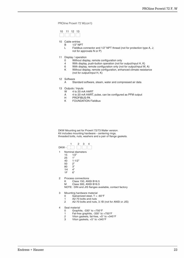
PROline Prowirl 72 W(con’t)
10 Cable entriesB 1/2” NPTL Fieldbus connector and 1/2” NPT thread (not for protection type A, J;
not for approvals N or P)
11 Display / operation0 Without display, remote configuration only4 With display, push-button operation (not for output/input H, K)6 With display, remote configuration only (not for output/input W, A)K Without display, remote configuration, enhanced climate resistance
(not for output/input H, K)
12 SoftwareA Standard software, steam, water and compressed air data
13 Outputs / InputsW 4 to 20 mA HARTA 4 to 20 mA HART, pulse, can be configured as PFM outputH PROFIBUS-PAK FOUNDATION Fieldbus
10 11 12 13
DKW -
DKW Mounting set for Prowirl 72/73 Wafer version.Kit includes mounting hardware - centering rings,threaded bolts, nuts, washers and a pair of flange gaskets.
1 Nominal diameters15 1/2”25 1”40 1-1/2”50 2”80 3”1H 4”1F 6”
2 Process connectionsK Class 150, ANSI B16.5M Class 300, ANSI B16.5NOTE: DIN and JIS flanges available, contact factory
3 Mounting hardware material0 Galvanized steel, T > -60°F1 A2-70 bolts and nuts2 A2-70 bolts and nuts, 3.1B (not for ANSI or JIS)
4 Seal material0 Graphite, -330° to +750°F1 Fat-free graphite, -330° to +750°F2 Viton gaskets, fat-free, +5° to +345°F3 Viton gaskets, +5° to +345°F
1 2 3 4

DK7ST -
DKST Stainless steel flow conditionerfor Prowirl 72/73, -330° to +750°F
1 Nominal diameters15 1/2”25 1”40 1-1/2”50 2”80 3”1H 4”1F 6”2H 8”2F 10”3H 12”
2 Process connectionsK Class 150, Schedule 40, ANSI B16.5M Class 300, Schedule 40, ANSI B16.5NOTE: DIN and JIS flanges available, contact factory
3 Material0 316L Stainless steel1 316L Stainless steel, 3.1B
1 2 3
United States
Endress+Hauser, Inc.2350 Endress PlaceGreenwood, IN 46143Phone: (317) 535-7138888-ENDRESSFAX: (317) 535-8498
TI 062D/24/ae/12.03© 2003 Endress+Hauser, Inc.
Canada
Endress+HauserCanada Ltd.1440 Graham’s LaneUnit 1, BurlingtonON, L7S 1W3Phone: (905) 681-9292800-668-3199FAX: (905) 681-9444
Mexico
Endress+HauserPaseo del Pedregal No. 610Col. Jardines del Pedregal01900, Mexico D.F.MexicoPhone: (525) 568-2405FAX: (525) 568-7459
For application and selection assistance,in the U.S. call 888-ENDRESS
For total support of your installed base, 24 hoursa day, in the U.S. call 800-642-8737
Visit us on our web site, www.us.endress.com
Endress+HauserThe Power of Know How