Vorlesung Automotive Software Engineering Teil 7 Normen...
81
INFORMATIK ▪ CONSULTING ▪ SYSTEMS AG Vorlesung Automotive Software Engineering Teil 7 Normen und Standards (1-1) Sommersemester 2014 Prof. Dr. rer. nat. Bernhard Hohlfeld [email protected] Technische Universität Dresden, Fakultät Informatik Honorarprofessur Automotive Software Engineering
Transcript of Vorlesung Automotive Software Engineering Teil 7 Normen...
INFORMATIK ▪ CONSULTING ▪ SYSTEMS AG
Vorlesung Automotive Software Engineering Teil 7 Normen und Standards (1-1)
Sommersemester 2014
Prof. Dr. rer. nat. Bernhard Hohlfeld
Technische Universität Dresden, Fakultät InformatikHonorarprofessur Automotive Software Engineering
Prof. Dr. Bernhard Hohlfeld: Automotive Software Engineering, TU Dresden, Fakultät Informatik
Vorlesung Automotive Software Engineering
2
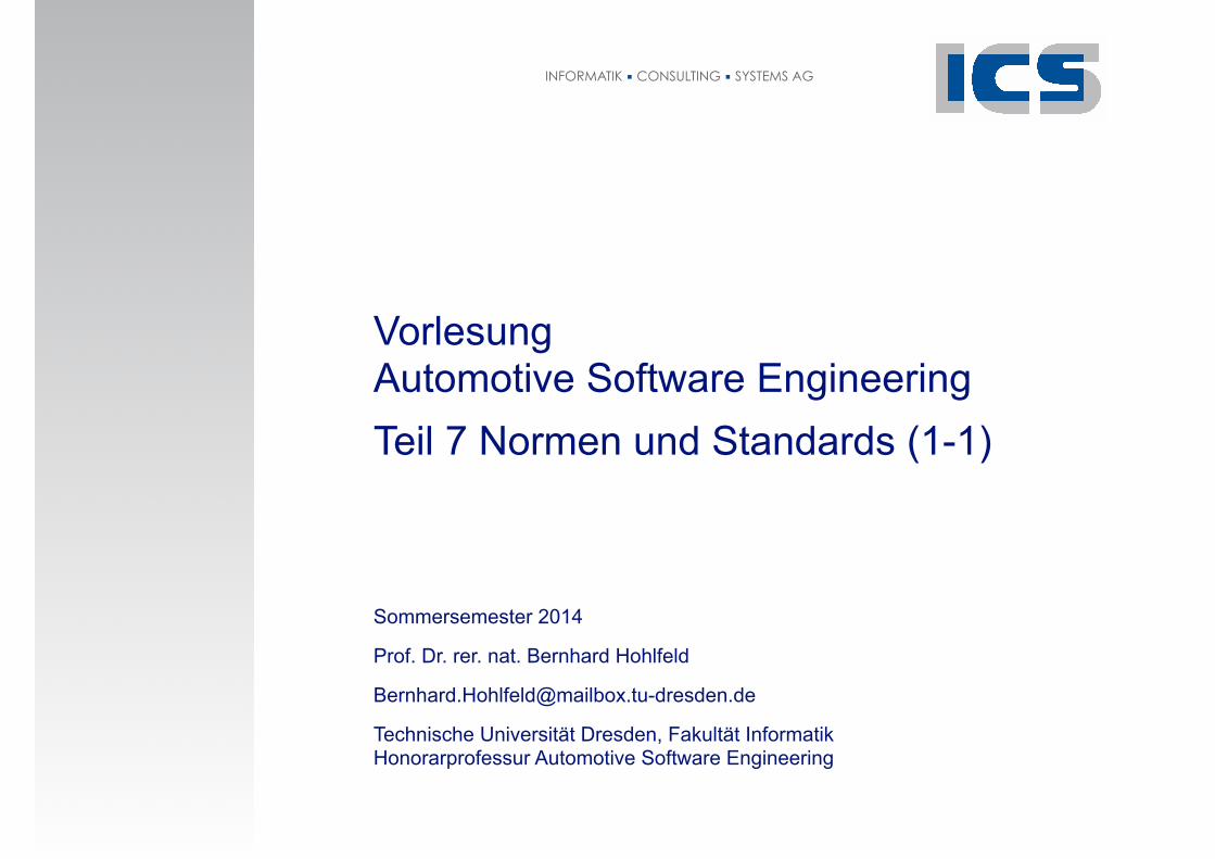
Motivation und Überblick
Beispiele aus der Praxis
SW-Entwicklung
Normen und Standards
E/E-Entwicklung
Das Automobil
Die Automobilherstellung
Die Automobilbranche
OSEK/ VDX
ASAM
ISO 26262 Road vehicles - Functional safety
Prof. Dr. Bernhard Hohlfeld: Automotive Software Engineering, TU Dresden, Fakultät Informatik
Lernziele Normen und Standards
! Die Bedeutung von Normen und Standards für industrielle Entwicklung verstehen.
! AUTOSAR Automotive Open System Architecture kennenlernen
! Motivation
! Technik
! Beispiele
! ISO 26262 Road Vehicles Functinal Safety kennenlernen
! Den Begriff COTS einordnen
! Entwurfs- und Codierstandards kennenlernen
3
Prof. Dr. Bernhard Hohlfeld: Automotive Software Engineering, TU Dresden, Fakultät Informatik
7. Normen und Standards
1. AUTOSAR
2. ARTOP
3. ISO 26262 - Road Vehicles - Functional Safety
4. COTS
5. Entwurfs- und Codierstandards
24
Prof. Dr. Bernhard Hohlfeld: Automotive Software Engineering, TU Dresden, Fakultät Informatik 2
1. AUTOSAR
2. ARTOP
3. ISO 26262 - Road Vehicles - Functional Safety
4. COTS
5. Entwurfs- und Codierstandards
7. Normen und Standards
5
Prof. Dr. Bernhard Hohlfeld: Automotive Software Engineering, TU Dresden, Fakultät Informatik
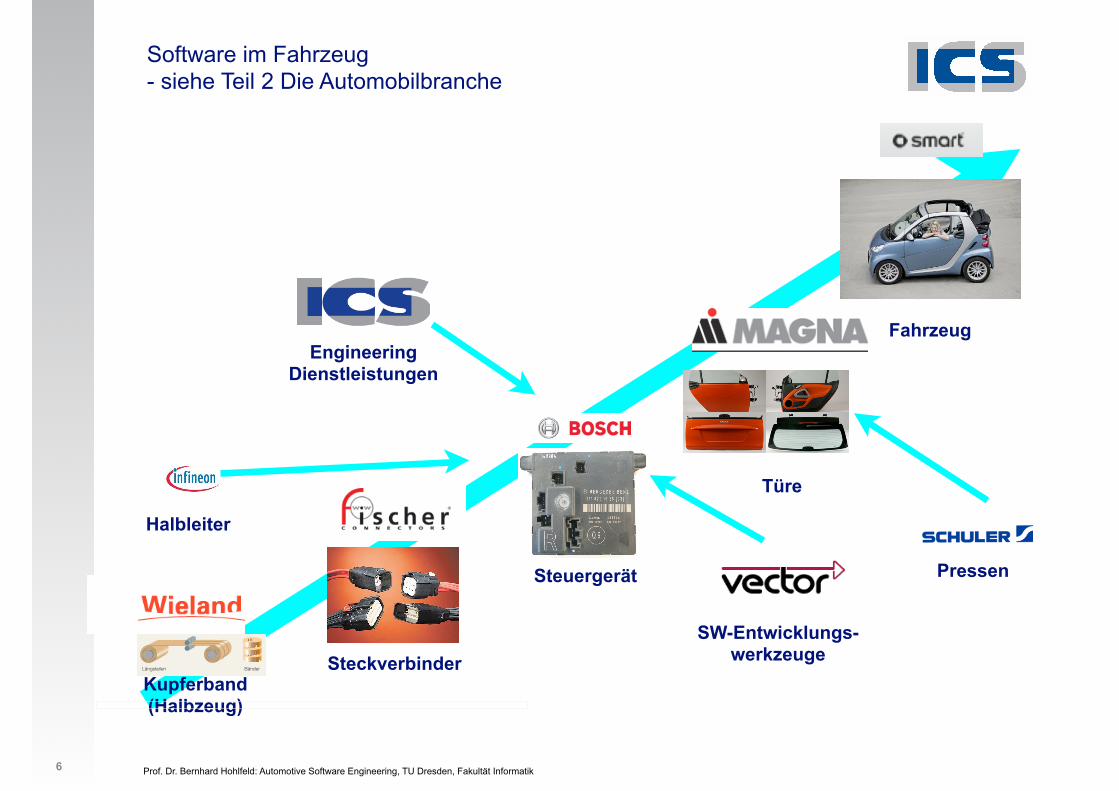
Software im Fahrzeug - siehe Teil 2 Die Automobilbranche
6
Kupferband(Halbzeug)
Anwärmen
Fräsen
Querteilen
Längsteilen
kalt Vorwalzen
Zwischen und Fertigwalzen
Warmwalzen
Inspektion
Bleche
Bänder
Schema der Fertigung vonBändern und Blechen
14
Steckverbinder
Türe
Fahrzeug
SW-Entwicklungs- werkzeuge
Engineering Dienstleistungen
Halbleiter
PressenSteuergerät
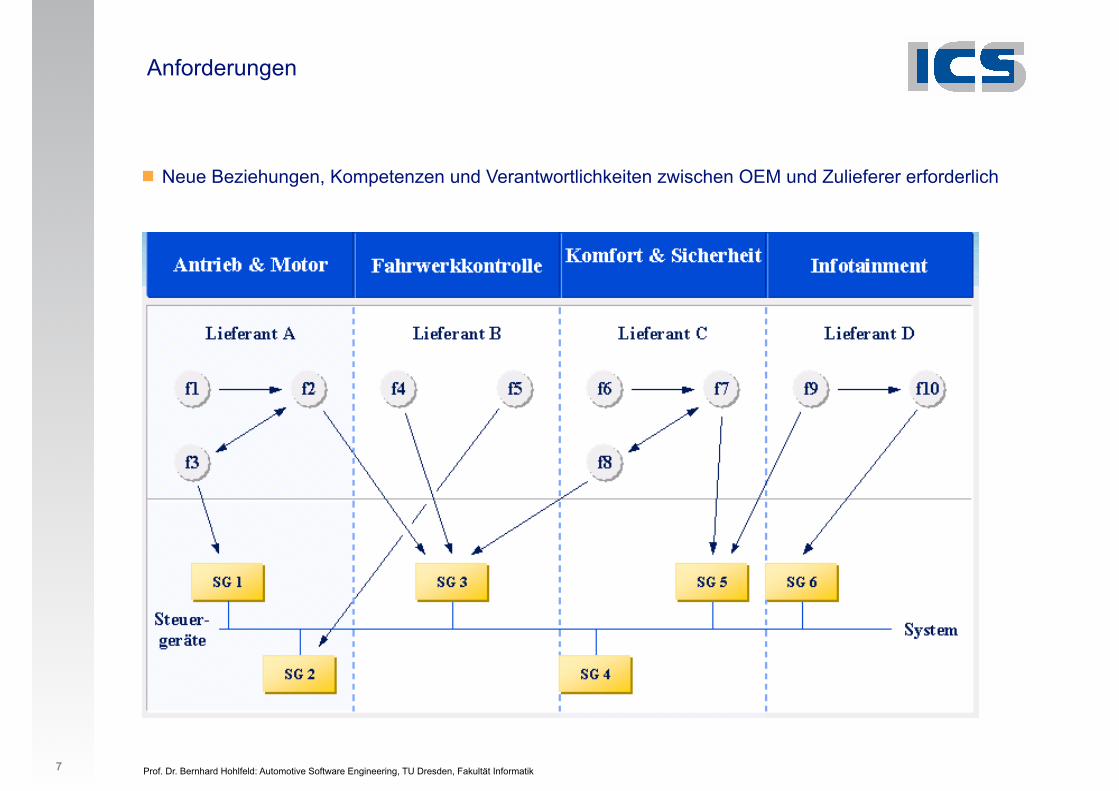
! Neue Beziehungen, Kompetenzen und Verantwortlichkeiten zwischen OEM und Zulieferer erforderlich
Prof. Dr. Bernhard Hohlfeld: Automotive Software Engineering, TU Dresden, Fakultät Informatik
Anforderungen
7
Prof. Dr. Bernhard Hohlfeld: Automotive Software Engineering, TU Dresden, Fakultät Informatik 2
1. Organisation
2. Schichtenmodell
3. Systementwicklung
4. Bussysteme im KFZ
5. Software-Architektur
6. Anwendungsbeispiele
7. Geplante AUTOSAR-Anwendungen
7. Normen und Standards 1. AUTOSAR
8
Prof. Dr. Bernhard Hohlfeld: Automotive Software Engineering, TU Dresden, Fakultät Informatik
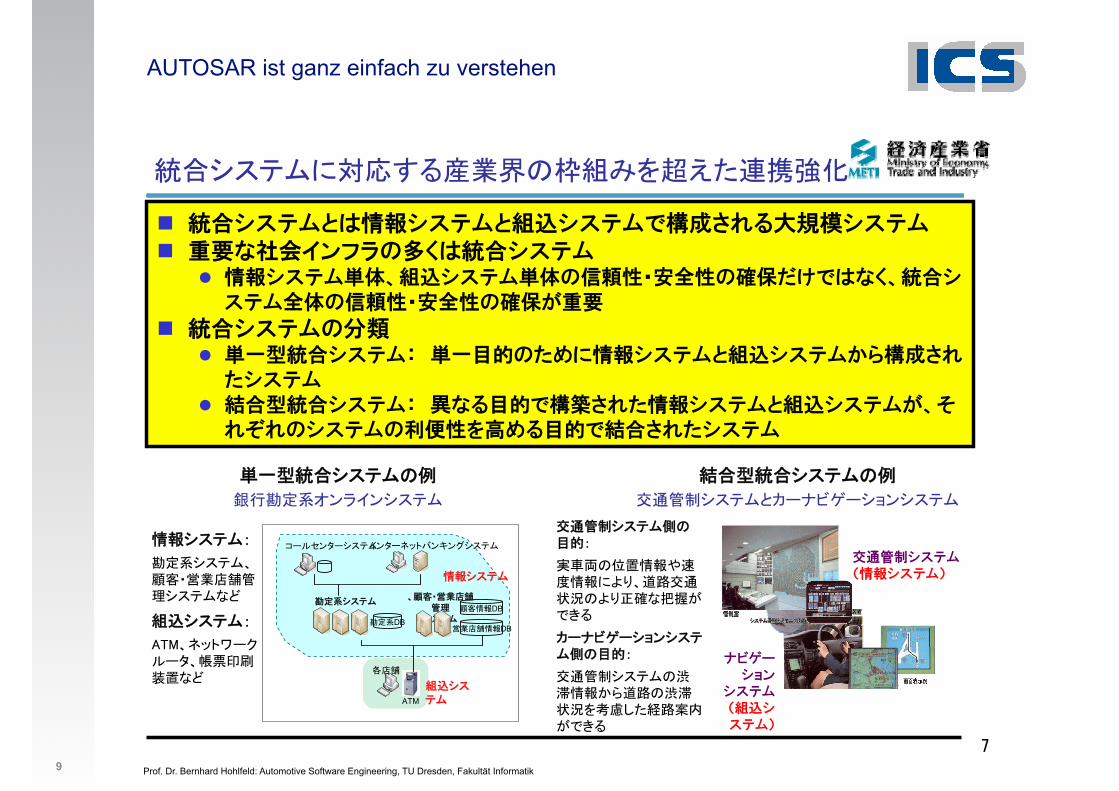
AUTOSAR ist ganz einfach zu verstehen
9*
5�efjpT��N[*#+U!2V\;IOA ��
� ! BCDH6:��BCDH6�$BCDH5��0>=�#�BCDH� &"7��@KGJ9�.:! BCDH
� ��BCDH��+�$BCDH��9�'�L���9��4/5:7.+! BCDH��9�'�L���9��-&"
� ! BCDH9(� ���! BCDHP ����93;8��BCDH6�$BCDH,<��0>3BCDH
� �! BCDHP �7=��5��0>3��BCDH6�$BCDH-+1>2>9BCDH9��?);=��5 0>3BCDH
�1efjp
�1DB
HD�v�#�80)efjp
D���DB
�#�8��DB
ATM
��8
dwsguhwefjp]uhwmiknu`ubefjp
2>efjp
��efjp
�%��BCDHN��BCDHO
EFAMBIK
BCDHN�$BCDHO
���5�efjpU�
C9�1^ur]uefjp
4��5�efjpU�
�?0�efjpQ_wlocwequefjp
��efjpx
�1efjpHD�v�#�80)efjpSR
2>efjpx
EGFHmiktwaswhH�/ :6SR
�?0�efjp�U-,x
�=�U�6��W@���TXZHB<�?(%UXZ$.S��KPL[
_wlocwequefjp�U-,x
�?0�efjpU&'��JYB<U&'(%\7�MO3<"�KPL[

Prof. Dr. Bernhard Hohlfeld: Automotive Software Engineering, TU Dresden, Fakultät Informatik 2
1. Organisation
2. Schichtenmodell
3. Systementwicklung
4. Bussysteme im KFZ
5. Software-Architektur
6. Anwendungsbeispiele
7. Geplante AUTOSAR-Anwendungen
7. Normen und Standards 1. AUTOSAR
10
Prof. Dr. Bernhard Hohlfeld: Automotive Software Engineering, TU Dresden, Fakultät Informatik
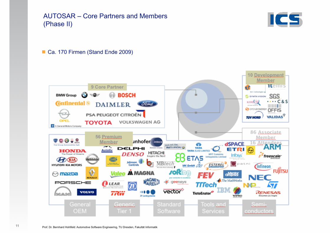
AUTOSAR – Core Partners and Members (Phase II)
! Ca. 170 Firmen (Stand Ende 2009)
11
Prof. Dr. Bernhard Hohlfeld: Automotive Software Engineering, TU Dresden, Fakultät Informatik
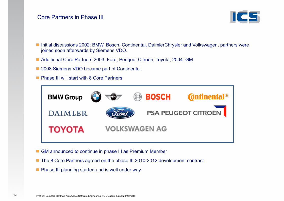
Core Partners in Phase III
! Initial discussions 2002: BMW, Bosch, Continental, DaimlerChrysler and Volkswagen, partners were joined soon afterwards by Siemens VDO.
! Additional Core Partners 2003: Ford, Peugeot Citroën, Toyota, 2004: GM
! 2008 Siemens VDO became part of Continental.
! Phase III will start with 8 Core Partners
!!!!!!!
! GM announced to continue in phase III as Premium Member
! The 8 Core Partners agreed on the phase III 2010-2012 development contract
! Phase III planning started and is well under way
12
Prof. Dr. Bernhard Hohlfeld: Automotive Software Engineering, TU Dresden, Fakultät Informatik
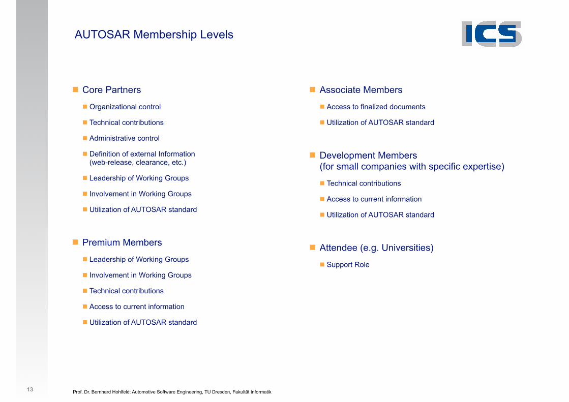
AUTOSAR Membership Levels
! Core Partners
! Organizational control
! Technical contributions
! Administrative control
! Definition of external Information(web-release, clearance, etc.)
! Leadership of Working Groups
! Involvement in Working Groups
! Utilization of AUTOSAR standard
!! Premium Members
! Leadership of Working Groups
! Involvement in Working Groups
! Technical contributions
! Access to current information
! Utilization of AUTOSAR standard
!!!
! Associate Members
! Access to finalized documents
! Utilization of AUTOSAR standard
!! Development Members
(for small companies with specific expertise)
! Technical contributions
! Access to current information
! Utilization of AUTOSAR standard
!! Attendee (e.g. Universities)
! Support Role
13
Prof. Dr. Bernhard Hohlfeld: Automotive Software Engineering, TU Dresden, Fakultät Informatik
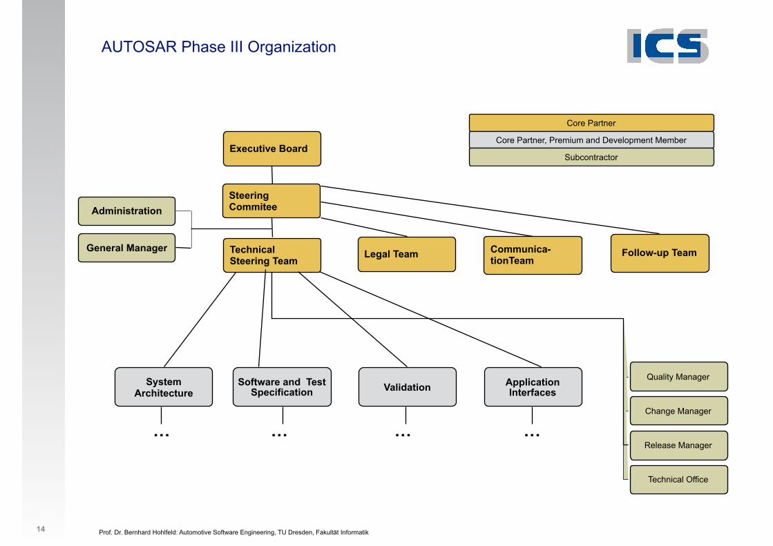
Executive Board
Legal Team Follow-up Team
Core Partner
Core Partner, Premium and Development Member
Subcontractor
System Architecture
Application Interfaces
Software and Test Specification Validation
Quality Manager
Change Manager
Release Manager
Technical Office
… … … …
Administration
General Manager
AUTOSAR Phase III Organization
14
Steering Commitee
Technical Steering Team
Communica-tionTeam
Prof. Dr. Bernhard Hohlfeld: Automotive Software Engineering, TU Dresden, Fakultät Informatik
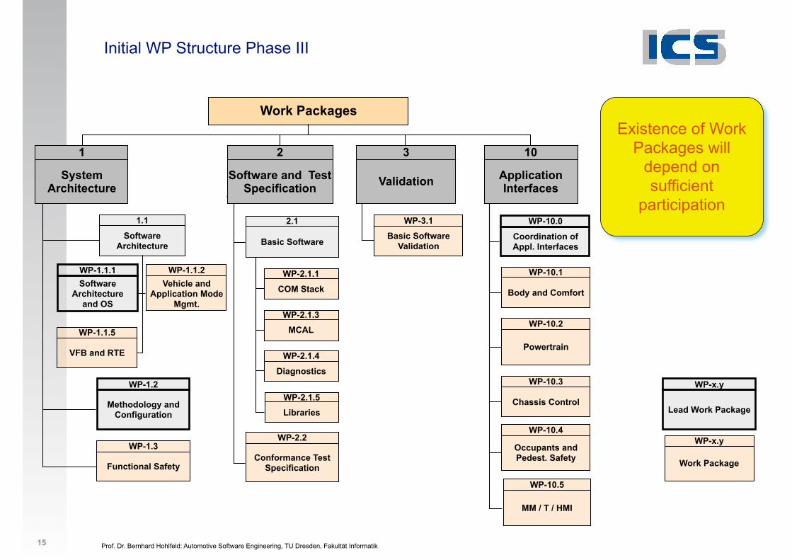
Initial WP Structure Phase III
Existence of Work Packages will
depend on sufficient
participation
Work Packages
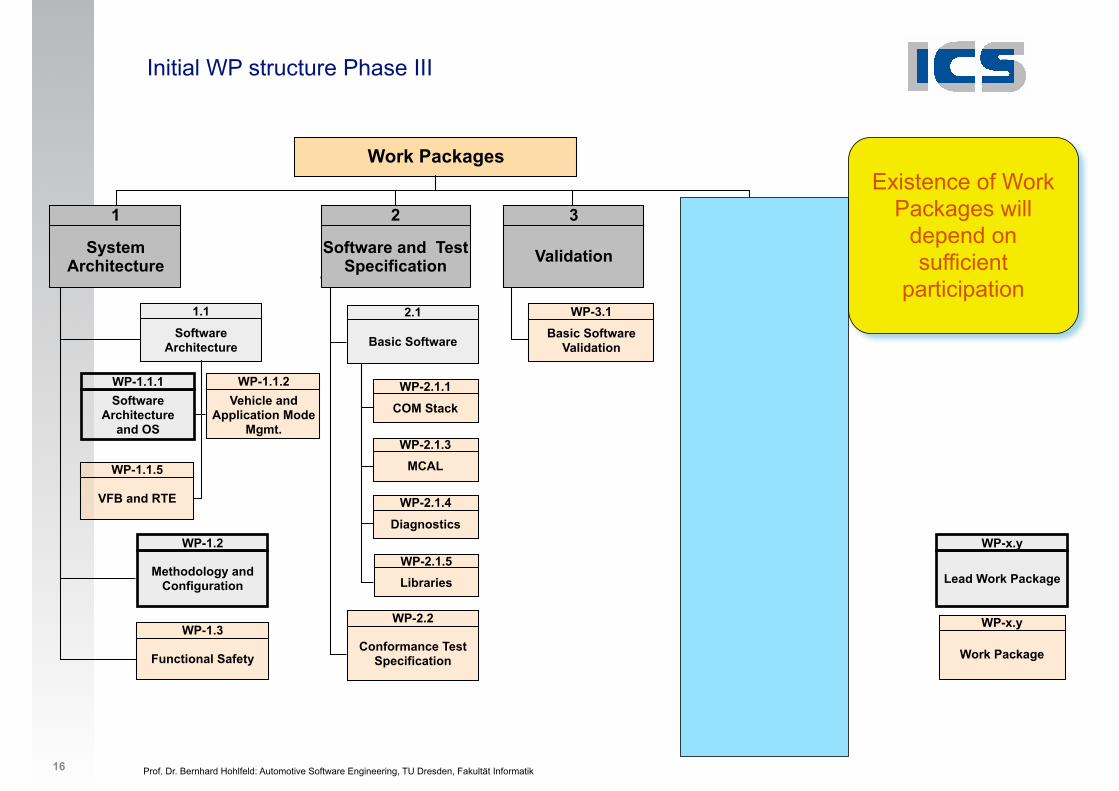
Functional Safety
WP-1.3
Body and Comfort
WP-10.1
Powertrain
WP-10.2
Chassis Control
WP-10.3
Occupants and Pedest. Safety
WP-10.4
Methodology and Configuration
WP-1.2
Conformance Test Specification
WP-2.2
Software Architecture
1.1
Software Architecture
and OS
WP-1.1.1Vehicle and
Application Mode Mgmt.
WP-1.1.2
COM Stack
WP-2.1.1
MCALWP-2.1.3
Diagnostics
WP-2.1.4
Basic Software
2.1Basic Software
Validation
WP-3.1
MM / T / HMI
WP-10.5
1
System Architecture
2
Software and Test Specification
3
Validation
Coordination of Appl. Interfaces
WP-10.0
10
Application Interfaces
LibrariesWP-2.1.5
VFB and RTE
WP-1.1.5
Lead Work Package
WP-x.y
Work Package
WP-x.y
15
Prof. Dr. Bernhard Hohlfeld: Automotive Software Engineering, TU Dresden, Fakultät Informatik
Initial WP structure Phase III
Existence of Work Packages will
depend on sufficient
participation
Work Packages
Functional Safety
WP-1.3
Body and Comfort
WP-10.1
Powertrain
WP-10.2
Chassis Control
WP-10.3
Occupants and Pedest. Safety
WP-10.4
Methodology and Configuration
WP-1.2
Conformance Test Specification
WP-2.2
Software Architecture
1.1
Software Architecture
and OS
WP-1.1.1Vehicle and
Application Mode Mgmt.
WP-1.1.2
COM Stack
WP-2.1.1
MCALWP-2.1.3
Diagnostics
WP-2.1.4
Basic Software
2.1Basic Software
Validation
WP-3.1
MM / T / HMI
WP-10.5
1
System Architecture
2
Software and Test Specification
3
Validation
Coordination of Appl. Interfaces
WP-10.0
10
Application Interfaces
LibrariesWP-2.1.5
VFB and RTE
WP-1.1.5
Lead Work Package
WP-x.y
Work Package
WP-x.y
16
Prof. Dr. Bernhard Hohlfeld: Automotive Software Engineering, TU Dresden, Fakultät Informatik
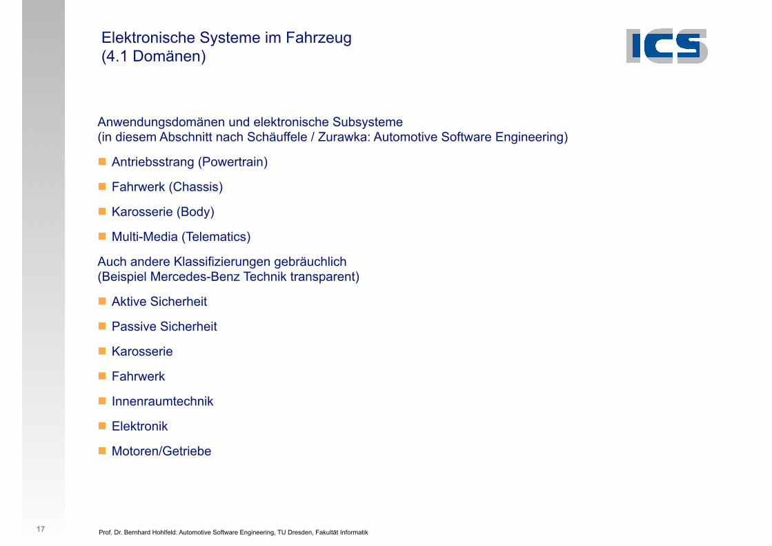
Elektronische Systeme im Fahrzeug (4.1 Domänen)
Anwendungsdomänen und elektronische Subsysteme(in diesem Abschnitt nach Schäuffele / Zurawka: Automotive Software Engineering)
! Antriebsstrang (Powertrain)
! Fahrwerk (Chassis)
! Karosserie (Body)
! Multi-Media (Telematics)
Auch andere Klassifizierungen gebräuchlich (Beispiel Mercedes-Benz Technik transparent)
! Aktive Sicherheit
! Passive Sicherheit
! Karosserie
! Fahrwerk
! Innenraumtechnik
! Elektronik
! Motoren/Getriebe
17
Prof. Dr. Bernhard Hohlfeld: Automotive Software Engineering, TU Dresden, Fakultät Informatik
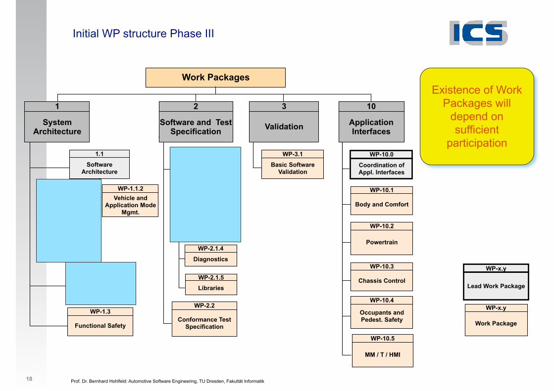
Initial WP structure Phase III
Existence of Work Packages will
depend on sufficient
participation
Work Packages
Functional Safety
WP-1.3
Body and Comfort
WP-10.1
Powertrain
WP-10.2
Chassis Control
WP-10.3
Occupants and Pedest. Safety
WP-10.4
Methodology and Configuration
WP-1.2
Conformance Test Specification
WP-2.2
Software Architecture
1.1
Software Architecture
and OS
WP-1.1.1Vehicle and
Application Mode Mgmt.
WP-1.1.2
COM Stack
WP-2.1.1
MCALWP-2.1.3
Diagnostics
WP-2.1.4
Basic Software
2.1Basic Software
Validation
WP-3.1
MM / T / HMI
WP-10.5
1
System Architecture
2
Software and Test Specification
3
Validation
Coordination of Appl. Interfaces
WP-10.0
10
Application Interfaces
LibrariesWP-2.1.5
VFB and RTE
WP-1.1.5
Lead Work Package
WP-x.y
Work Package
WP-x.y
18
Prof. Dr. Bernhard Hohlfeld: Automotive Software Engineering, TU Dresden, Fakultät Informatik
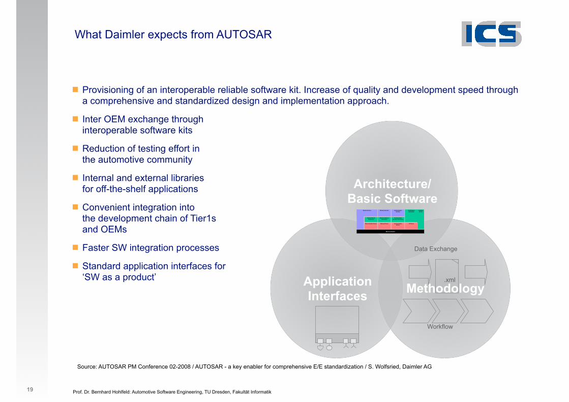
What Daimler expects from AUTOSAR
! Provisioning of an interoperable reliable software kit. Increase of quality and development speed through a comprehensive and standardized design and implementation approach.
! Inter OEM exchange through interoperable software kits
! Reduction of testing effort inthe automotive community
! Internal and external libraries for off-the-shelf applications
! Convenient integration into the development chain of Tier1s and OEMs
! Faster SW integration processes
! Standard application interfaces for‘SW as a product’
19
Source: AUTOSAR PM Conference 02-2008 / AUTOSAR - a key enabler for comprehensive E/E standardization / S. Wolfsried, Daimler AG
ApplicationInterfaces Methodology
Architecture/ Basic Software
Workflow
! .xml
Data Exchange
Prof. Dr. Bernhard Hohlfeld: Automotive Software Engineering, TU Dresden, Fakultät Informatik
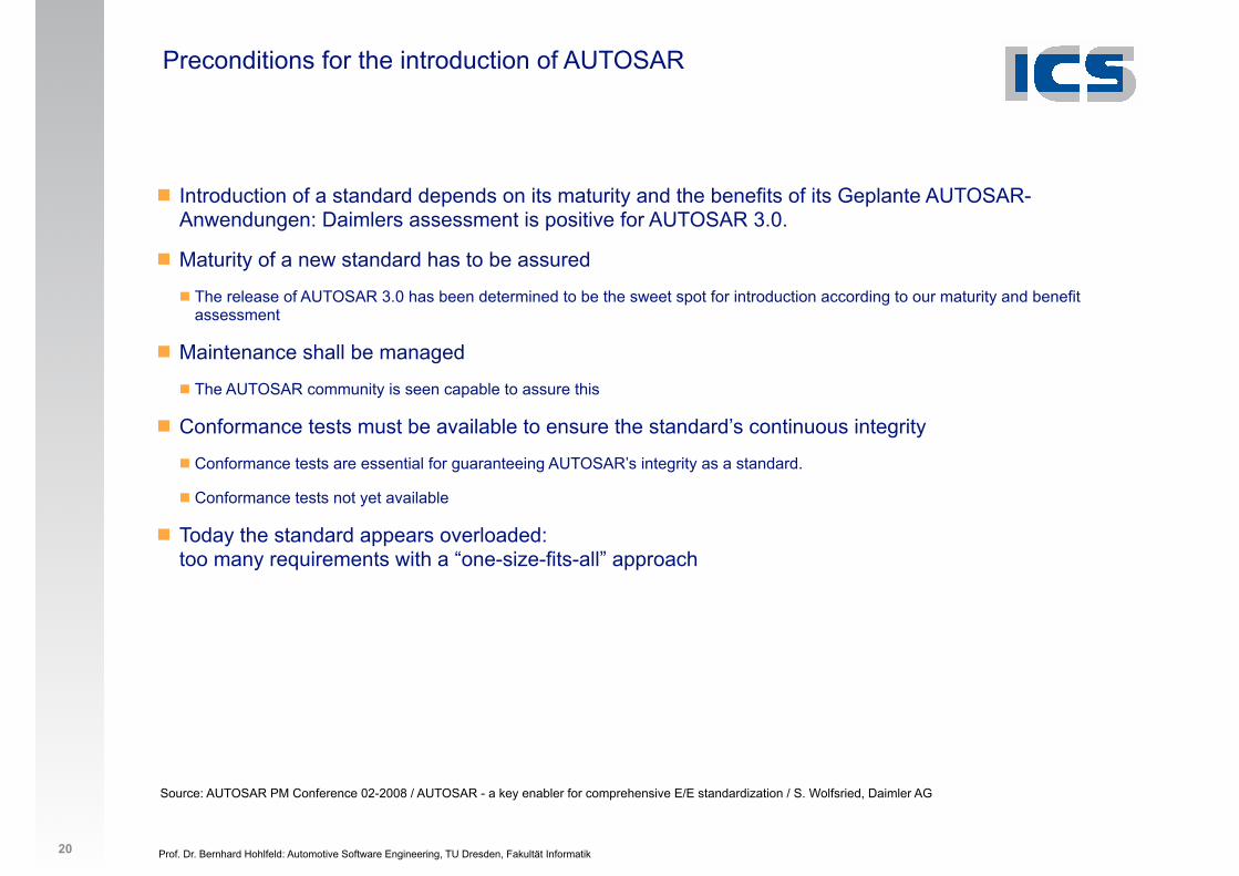
Preconditions for the introduction of AUTOSAR
! Introduction of a standard depends on its maturity and the benefits of its Geplante AUTOSAR-Anwendungen: Daimlers assessment is positive for AUTOSAR 3.0.
! Maturity of a new standard has to be assured
! The release of AUTOSAR 3.0 has been determined to be the sweet spot for introduction according to our maturity and benefit assessment
! Maintenance shall be managed
! The AUTOSAR community is seen capable to assure this
! Conformance tests must be available to ensure the standard’s continuous integrity
! Conformance tests are essential for guaranteeing AUTOSAR’s integrity as a standard.
! Conformance tests not yet available
! Today the standard appears overloaded: too many requirements with a “one-size-fits-all” approach
20
Source: AUTOSAR PM Conference 02-2008 / AUTOSAR - a key enabler for comprehensive E/E standardization / S. Wolfsried, Daimler AG

Prof. Dr. Bernhard Hohlfeld: Automotive Software Engineering, TU Dresden, Fakultät Informatik 21
AUTOSAR TutorialOct. 23rd 20089
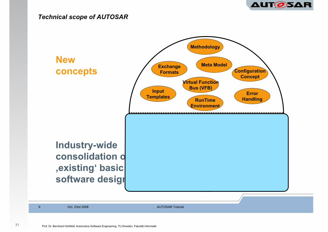
Technical scope of AUTOSAR
Industry-wide
consolidation of
‚existing‘ basic
software designs
New
concepts
OS Kernel
Memory
Services
µController
Abstraction
ECU
Abstraction
Diagnostics
Complex
Drivers
Bus systems
Mode
Management
Gateway
Network
Management
Comm.
Services
Drivers
RunTime
Environment
Configuration
Concept
Exchange
Formats
Input
Templates
Methodology
Virtual Function
Bus (VFB)
Meta Model
Error
Handling
Prof. Dr. Bernhard Hohlfeld: Automotive Software Engineering, TU Dresden, Fakultät Informatik 21
AUTOSAR TutorialOct. 23rd 20089
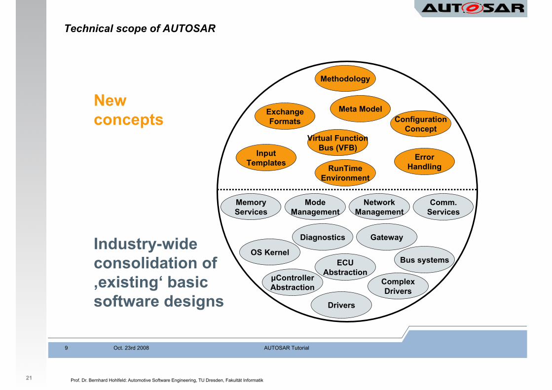
Technical scope of AUTOSAR
Industry-wide
consolidation of
‚existing‘ basic
software designs
New
concepts
OS Kernel
Memory
Services
µController
Abstraction
ECU
Abstraction
Diagnostics
Complex
Drivers
Bus systems
Mode
Management
Gateway
Network
Management
Comm.
Services
Drivers
RunTime
Environment
Configuration
Concept
Exchange
Formats
Input
Templates
Methodology
Virtual Function
Bus (VFB)
Meta Model
Error
Handling
Prof. Dr. Bernhard Hohlfeld: Automotive Software Engineering, TU Dresden, Fakultät Informatik 21
AUTOSAR TutorialOct. 23rd 20089
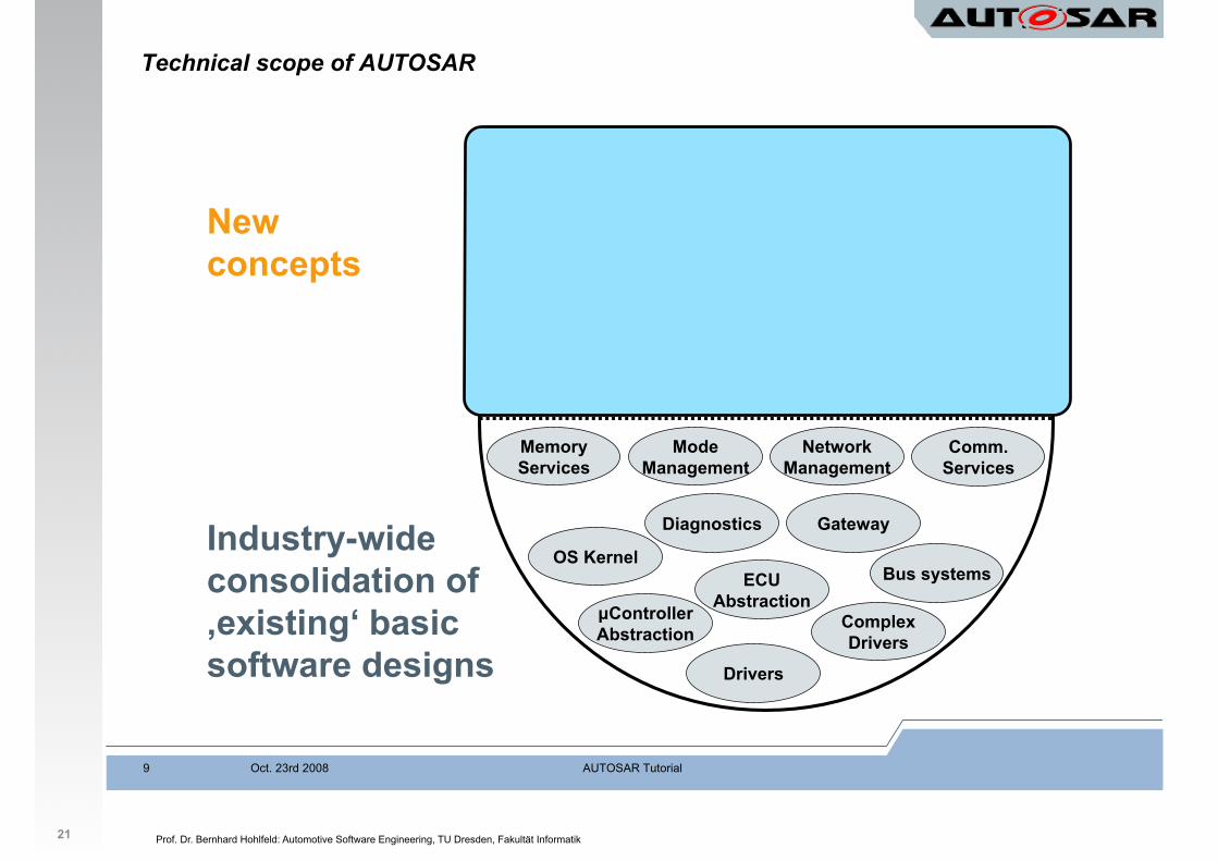
Technical scope of AUTOSAR
Industry-wide
consolidation of
‚existing‘ basic
software designs
New
concepts
OS Kernel
Memory
Services
µController
Abstraction
ECU
Abstraction
Diagnostics
Complex
Drivers
Bus systems
Mode
Management
Gateway
Network
Management
Comm.
Services
Drivers
RunTime
Environment
Configuration
Concept
Exchange
Formats
Input
Templates
Methodology
Virtual Function
Bus (VFB)
Meta Model
Error
Handling
Prof. Dr. Bernhard Hohlfeld: Automotive Software Engineering, TU Dresden, Fakultät Informatik 21
AUTOSAR TutorialOct. 23rd 20089
Technical scope of AUTOSAR
Industry-wide
consolidation of
‚existing‘ basic
software designs
New
concepts
OS Kernel
Memory
Services
µController
Abstraction
ECU
Abstraction
Diagnostics
Complex
Drivers
Bus systems
Mode
Management
Gateway
Network
Management
Comm.
Services
Drivers
RunTime
Environment
Configuration
Concept
Exchange
Formats
Input
Templates
Methodology
Virtual Function
Bus (VFB)
Meta Model
Error
Handling
Prof. Dr. Bernhard Hohlfeld: Automotive Software Engineering, TU Dresden, Fakultät Informatik 22
AUTOSAR TutorialOct. 23rd 20089
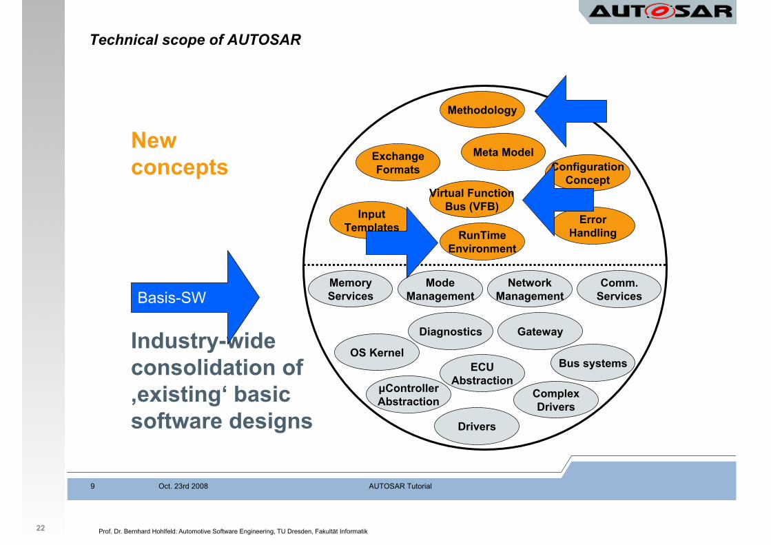
Technical scope of AUTOSAR
Industry-wide
consolidation of
‚existing‘ basic
software designs
New
concepts
OS Kernel
Memory
Services
µController
Abstraction
ECU
Abstraction
Diagnostics
Complex
Drivers
Bus systems
Mode
Management
Gateway
Network
Management
Comm.
Services
Drivers
RunTime
Environment
Configuration
Concept
Exchange
Formats
Input
Templates
Methodology
Virtual Function
Bus (VFB)
Meta Model
Error
Handling
Basis-SW

Prof. Dr. Bernhard Hohlfeld: Automotive Software Engineering, TU Dresden, Fakultät Informatik 2
1. Organisation
2. Schichtenmodell
3. Systementwicklung
4. Bussysteme im KFZ
5. Software-Architektur
6. Anwendungsbeispiele
7. Geplante AUTOSAR-Anwendungen
7. Normen und Standards 1. AUTOSAR
23
Prof. Dr. Bernhard Hohlfeld: Automotive Software Engineering, TU Dresden, Fakultät Informatik
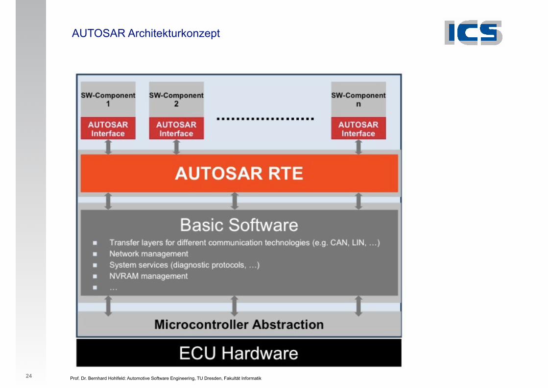
AUTOSAR Architekturkonzept
24
Prof. Dr. Bernhard Hohlfeld: Automotive Software Engineering, TU Dresden, Fakultät Informatik
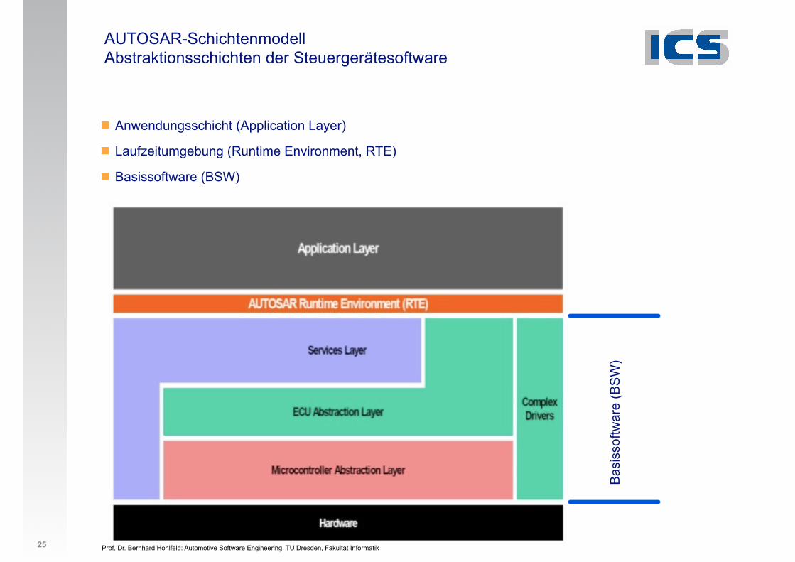
AUTOSAR-Schichtenmodell Abstraktionsschichten der Steuergerätesoftware
25
! Anwendungsschicht (Application Layer)
! Laufzeitumgebung (Runtime Environment, RTE)
! Basissoftware (BSW)
Bas
isso
ftwar
e (B
SW
)
Prof. Dr. Bernhard Hohlfeld: Automotive Software Engineering, TU Dresden, Fakultät Informatik
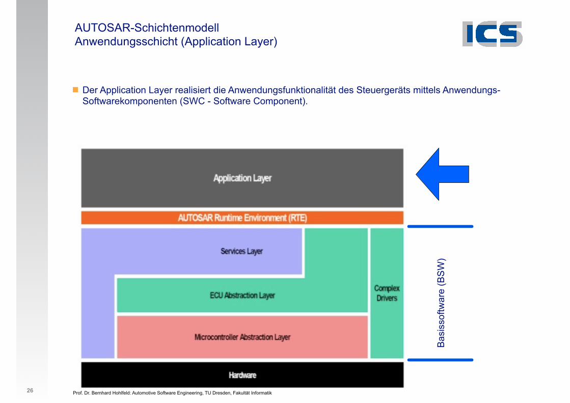
AUTOSAR-Schichtenmodell Anwendungsschicht (Application Layer)
26
! Der Application Layer realisiert die Anwendungsfunktionalität des Steuergeräts mittels Anwendungs-Softwarekomponenten (SWC - Software Component).
Bas
isso
ftwar
e (B
SW
)
Prof. Dr. Bernhard Hohlfeld: Automotive Software Engineering, TU Dresden, Fakultät Informatik
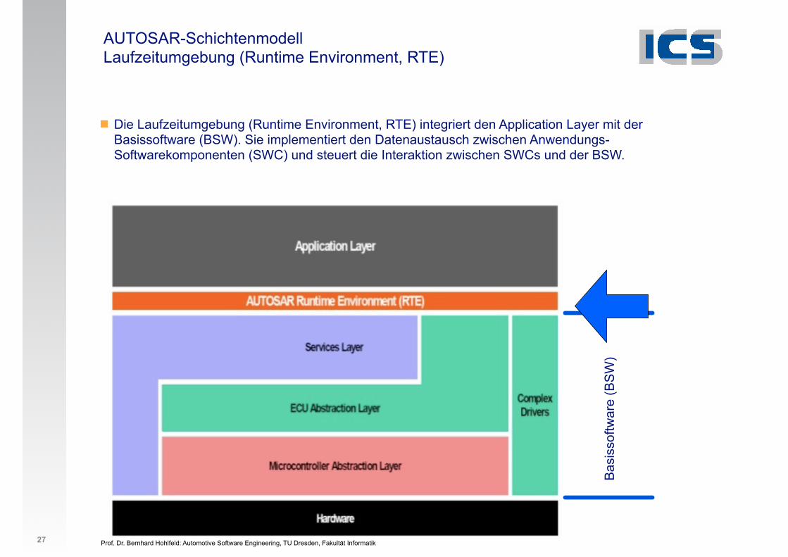
AUTOSAR-Schichtenmodell Laufzeitumgebung (Runtime Environment, RTE)
27
! Die Laufzeitumgebung (Runtime Environment, RTE) integriert den Application Layer mit der Basissoftware (BSW). Sie implementiert den Datenaustausch zwischen Anwendungs-Softwarekomponenten (SWC) und steuert die Interaktion zwischen SWCs und der BSW.
Bas
isso
ftwar
e (B
SW
)
Prof. Dr. Bernhard Hohlfeld: Automotive Software Engineering, TU Dresden, Fakultät Informatik
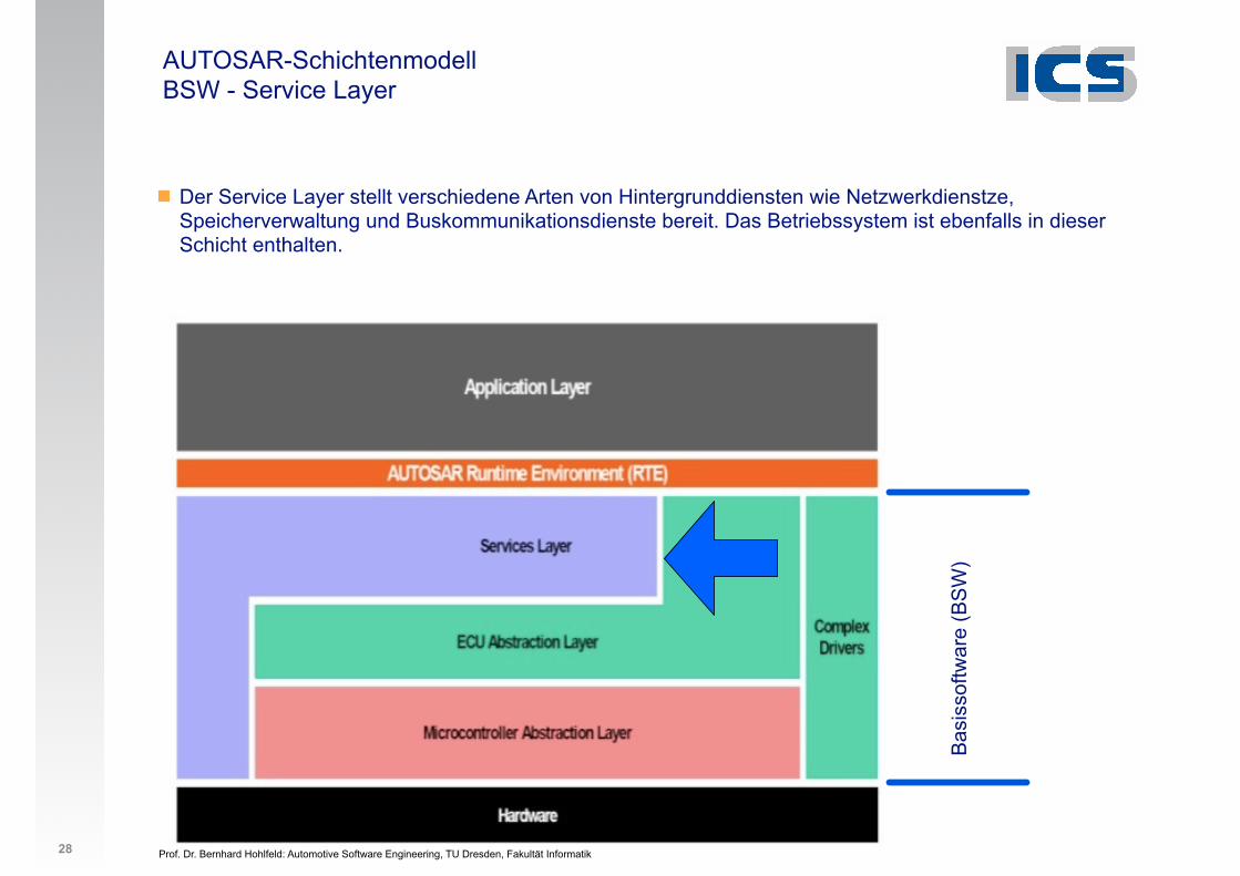
AUTOSAR-Schichtenmodell BSW - Service Layer
28
! Der Service Layer stellt verschiedene Arten von Hintergrunddiensten wie Netzwerkdienstze, Speicherverwaltung und Buskommunikationsdienste bereit. Das Betriebssystem ist ebenfalls in dieser Schicht enthalten.
Bas
isso
ftwar
e (B
SW
)
Prof. Dr. Bernhard Hohlfeld: Automotive Software Engineering, TU Dresden, Fakultät Informatik
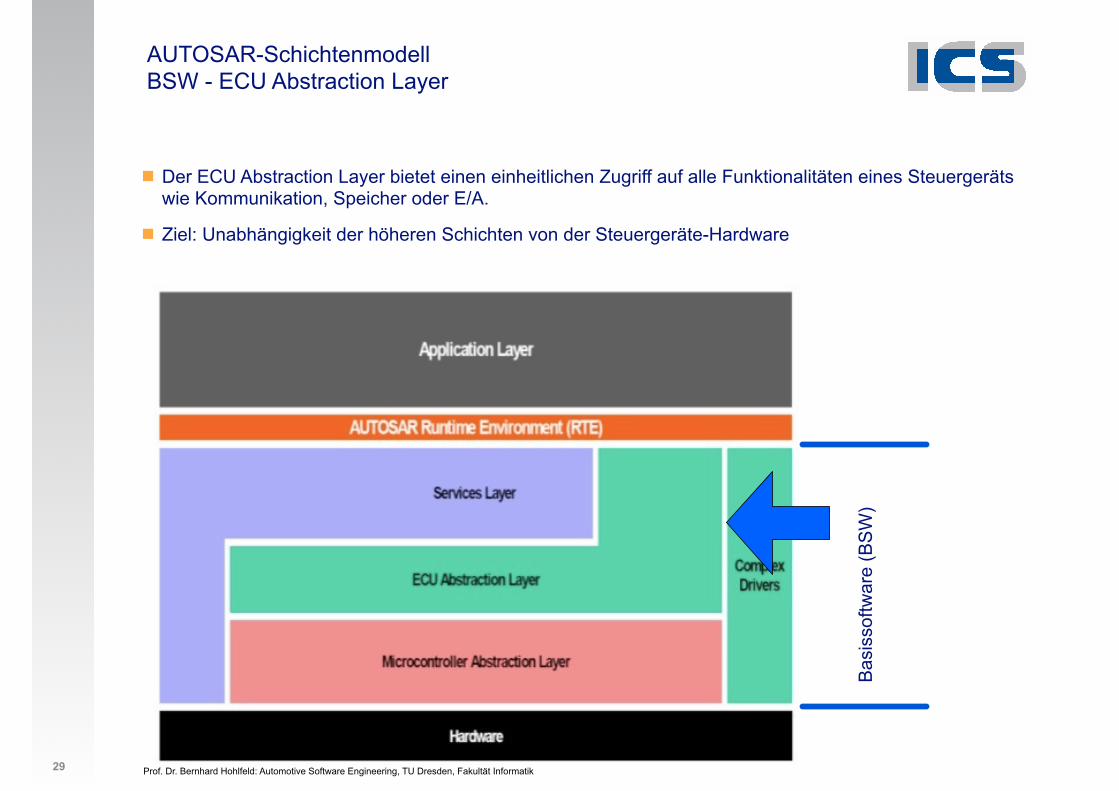
AUTOSAR-Schichtenmodell BSW - ECU Abstraction Layer
29
! Der ECU Abstraction Layer bietet einen einheitlichen Zugriff auf alle Funktionalitäten eines Steuergeräts wie Kommunikation, Speicher oder E/A.
! Ziel: Unabhängigkeit der höheren Schichten von der Steuergeräte-Hardware
Bas
isso
ftwar
e (B
SW
)
Prof. Dr. Bernhard Hohlfeld: Automotive Software Engineering, TU Dresden, Fakultät Informatik
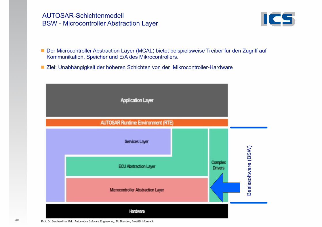
AUTOSAR-Schichtenmodell BSW - Microcontroller Abstraction Layer
30
! Der Microcontroller Abstraction Layer (MCAL) bietet beispielsweise Treiber für den Zugriff auf Kommunikation, Speicher und E/A des Mikrocontrollers.
! Ziel: Unabhängigkeit der höheren Schichten von der Mikrocontroller-Hardware
Bas
isso
ftwar
e (B
SW
)
Prof. Dr. Bernhard Hohlfeld: Automotive Software Engineering, TU Dresden, Fakultät Informatik
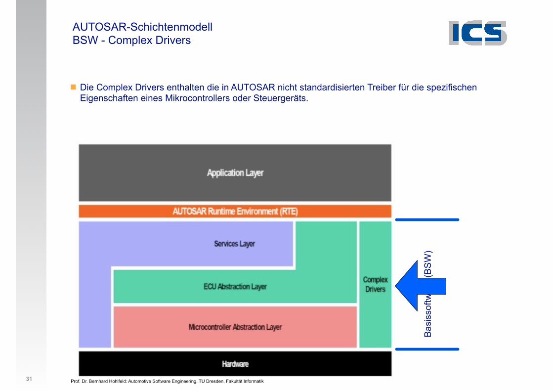
AUTOSAR-Schichtenmodell BSW - Complex Drivers
31
! Die Complex Drivers enthalten die in AUTOSAR nicht standardisierten Treiber für die spezifischen Eigenschaften eines Mikrocontrollers oder Steuergeräts.
Bas
isso
ftwar
e (B
SW
)
Prof. Dr. Bernhard Hohlfeld: Automotive Software Engineering, TU Dresden, Fakultät Informatik
AUTOSAR-Schichtenmodell BSW - Complex Drivers
32
! Die Complex Drivers enthalten die in AUTOSAR nicht standardisierten Treiber für die spezifischen Eigenschaften eines Mikrocontrollers oder Steuergeräts.
! Beispiele
! Sensordatenauswertung
! Direkter Zugriff auf Mikrocontroller
! Einfachlösungen für geringe Stückzahlen
! Zugriffszeiten (siehe unten)
! Weiterverwendung (siehe unten)
Prof. Dr. Bernhard Hohlfeld: Automotive Software Engineering, TU Dresden, Fakultät Informatik
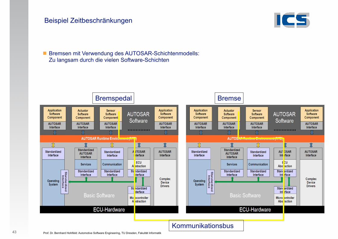
Beispiel Zeitbeschränkungen
! Bremsen mit Verwendung des AUTOSAR-Schichtenmodells: Zu langsam durch die vielen Software-Schichten
Bremspedal Bremse
Kommunikationsbus43
Prof. Dr. Bernhard Hohlfeld: Automotive Software Engineering, TU Dresden, Fakultät Informatik
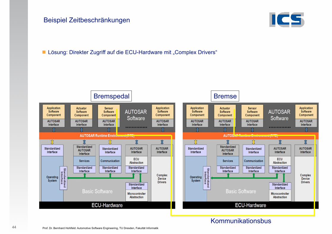
Beispiel Zeitbeschränkungen
! Lösung: Direkter Zugriff auf die ECU-Hardware mit „Complex Drivers“
Bremspedal Bremse
Kommunikationsbus44
Prof. Dr. Bernhard Hohlfeld: Automotive Software Engineering, TU Dresden, Fakultät Informatik
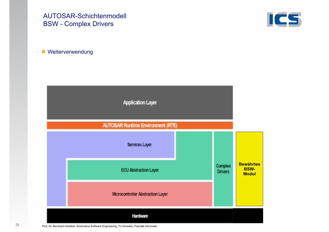
AUTOSAR-Schichtenmodell BSW - Complex Drivers
35
! Weiterverwendung
Bewährtes BSW-Modul
Prof. Dr. Bernhard Hohlfeld: Automotive Software Engineering, TU Dresden, Fakultät Informatik
AUTOSAR-Schichtenmodell BSW - Complex Drivers
36
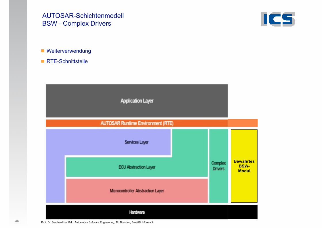
! Weiterverwendung
! RTE-Schnittstelle
Bewährtes BSW-Modul
Prof. Dr. Bernhard Hohlfeld: Automotive Software Engineering, TU Dresden, Fakultät Informatik
AUTOSAR-Schichtenmodell BSW - Complex Drivers
37
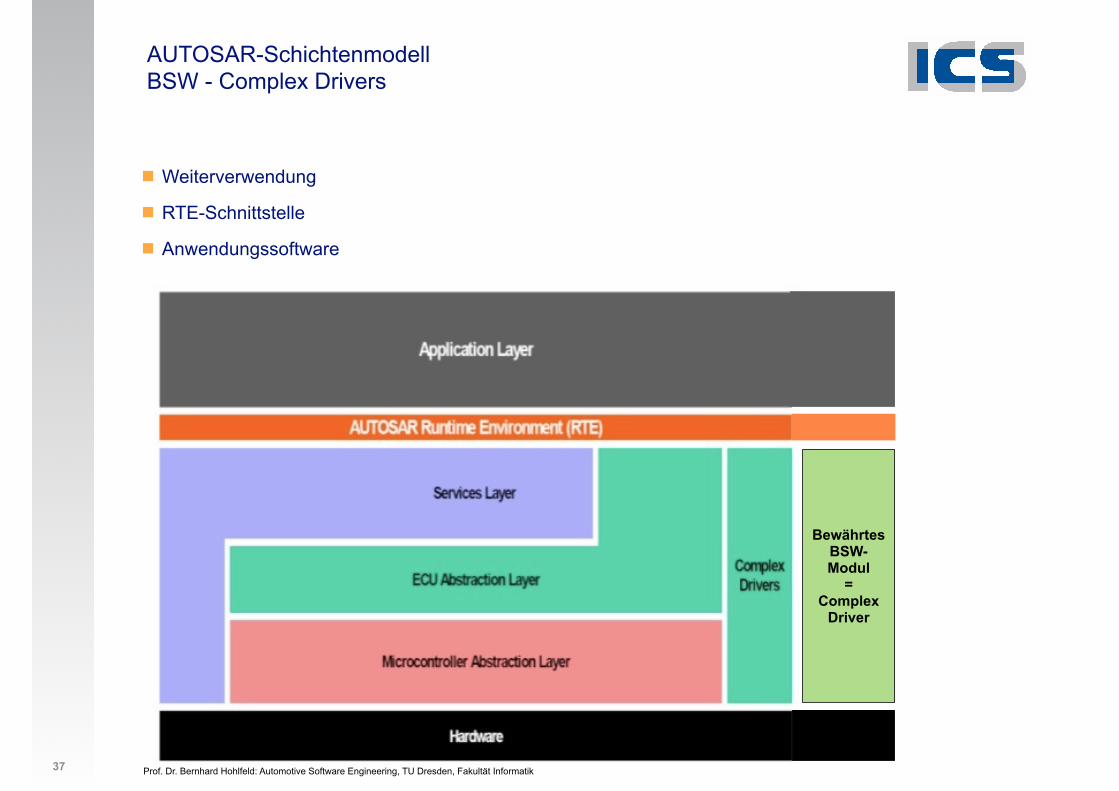
! Weiterverwendung
! RTE-Schnittstelle
! Anwendungssoftware
Bewährtes BSW-Modul
= Complex
Driver
Prof. Dr. Bernhard Hohlfeld: Automotive Software Engineering, TU Dresden, Fakultät Informatik
Case Study Entwicklung einer Treiberbibliothek für Motorsteuerungen mit AUTOSAR Complex Device Driver (CDD) (1) Quelle: Vector Informatik GmbH
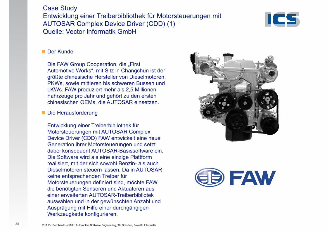
! Der KundeDie FAW Group Cooperation, die „First Automotive Works“, mit Sitz in Changchun ist der größte chinesische Hersteller von Dieselmotoren, PKWs, sowie mittleren bis schweren Bussen und LKWs. FAW produziert mehr als 2,5 Millionen Fahrzeuge pro Jahr und gehört zu den ersten chinesischen OEMs, die AUTOSAR einsetzen.
! Die HerausforderungEntwicklung einer Treiberbibliothek für Motorsteuerungen mit AUTOSAR Complex Device Driver (CDD) FAW entwickelt eine neue Generation ihrer Motorsteuerungen und setzt dabei konsequent AUTOSAR-Basissoftware ein. Die Software wird als eine einzige Plattform realisiert, mit der sich sowohl Benzin- als auch Dieselmotoren steuern lassen. Da in AUTOSAR keine entsprechenden Treiber für Motorsteuerungen definiert sind, möchte FAW die benötigten Sensoren und Aktuatoren aus einer erweiterten AUTOSAR-Treiberbibliotek auswählen und in der gewünschten Anzahl und Ausprägung mit Hilfe einer durchgängigen Werkzeugkette konfigurieren.
38
Der KundeDie FAW Group Cooperation, die „First Automotive Works“, mit Sitz in Changchun ist der größte chinesische Hersteller von Dieselmotoren, PKWs, sowie mittleren bis schweren Bussen und LKWs. FAW produziert mehr als 2,5 Millionen Fahrzeuge pro Jahr und gehört zu den ersten chinesischen OEMs, die AUTOSAR einsetzen.
Die HerausforderungEntwicklung einer Treiberbibliothek für Motorsteuerungen mit AUTOSAR Complex Device Driver (CDD)FAW entwickelt eine neue Generation ihrer Motorsteuerungen
und setzt dabei konsequent AUTOSAR-Basissoftware ein. Die
Software wird als eine einzige Plattform realisiert, mit der sich
sowohl Benzin- als auch Dieselmotoren steuern lassen. Da in
AUTOSAR keine entsprechenden Treiber für Motorsteuerun-
gen definiert sind, möchte FAW die benötigten Sensoren und
Aktuatoren aus einer erweiterten AUTOSAR-Treiberbibliotek
auswählen und in der gewünschten Anzahl und Ausprägung
mit Hilfe einer durchgängigen Werkzeugkette konfigurieren.
Die LösungKonfiguration und Code-Generierung der motorspezifi-schen Treiber mit der vorhandenen AUTOSAR-Werkzeug-kette von VectorDie Treiber zur Ansteuerung der motorspezifischen Sensorik
und Aktuatorik wurden von Vector als sogenannte Complex
Device Driver (CDD) realisiert. Für die Konfiguration der Trei-
ber wurden entsprechende Basissoftware Module Description
(BSWMD) Dateien mit Hilfe des DaVinci Configurator Kit er-
zeugt. Ebenso wurden die Code-Generatoren mit dem DaVinci
Configurator Kit erstellt. Der DaVinci Configurator Pro liest die
BSWMD-Dateien und bindet die zugehörigen Code Generatoren
ein. Damit kann er die Treiber für die Motorsteuerung und die
AUTOSAR-Basissoftware konfigurieren.
Die VorteileEine durch FAW erweiterbare domänenspezifische Treiber-bibliothek
Konfiguration und Generierung der gesamten Basissoft ware
mit einem Werkzeug: Sowohl die AUTOSAR-Standardmodule
als auch die speziellen Treiber für die Motorsteu erung wer-
den mit dem DaVinci Configurator Pro konfiguriert.
Die Treiberbibliothek kann mit dem DaVinci Configurator Kit
erweitert oder angepasst werden, z.B. wenn neue Sensoren
oder Aktuatoren eingeführt werden.
Reduzierter Verwaltungsaufwand durch Pflege und Erwei-
terung der Bibliothek in einer zentralen Abteilung. Die ver-
schiedenen Fahrzeugprojekte haben Zugriff auf die zentrale
Bibliothek und konfigurieren sie mit dem DaVinci
Configurator Pro entsprechend ihrer spezifischen Motor-
steuerung.
Der in AUTOSAR vorgegebene Prozess und die Schnittstel-
len werden eingehalten: Die Regelalgorithmen für die
Motorsteuerung werden weiterhin mit Matlab und Simulink
entwickelt und als AUTOSAR-Softwarekomponenten (SWC)
realisiert. Diese sind über die RTE mit der AUTOSAR-Basis-
software und den motorspezifischen Treibern verbunden.
Case StudyEntwicklung einer Treiberbibliothek für Motorsteuerungen mit AUTOSAR
Complex Device Driver (CDD)
V1.0
201
1/05
PES
_CS_
FAW
_CDD
-Mot
ortr
eibe
r_DE
Ihr Ansprechpartner bei Vector: Embedded Sales [email protected]
Prof. Dr. Bernhard Hohlfeld: Automotive Software Engineering, TU Dresden, Fakultät Informatik
Case Study Entwicklung einer Treiberbibliothek für Motorsteuerungen mit AUTOSAR Complex Device Driver (CDD) (2) Quelle: Vector Informatik GmbH
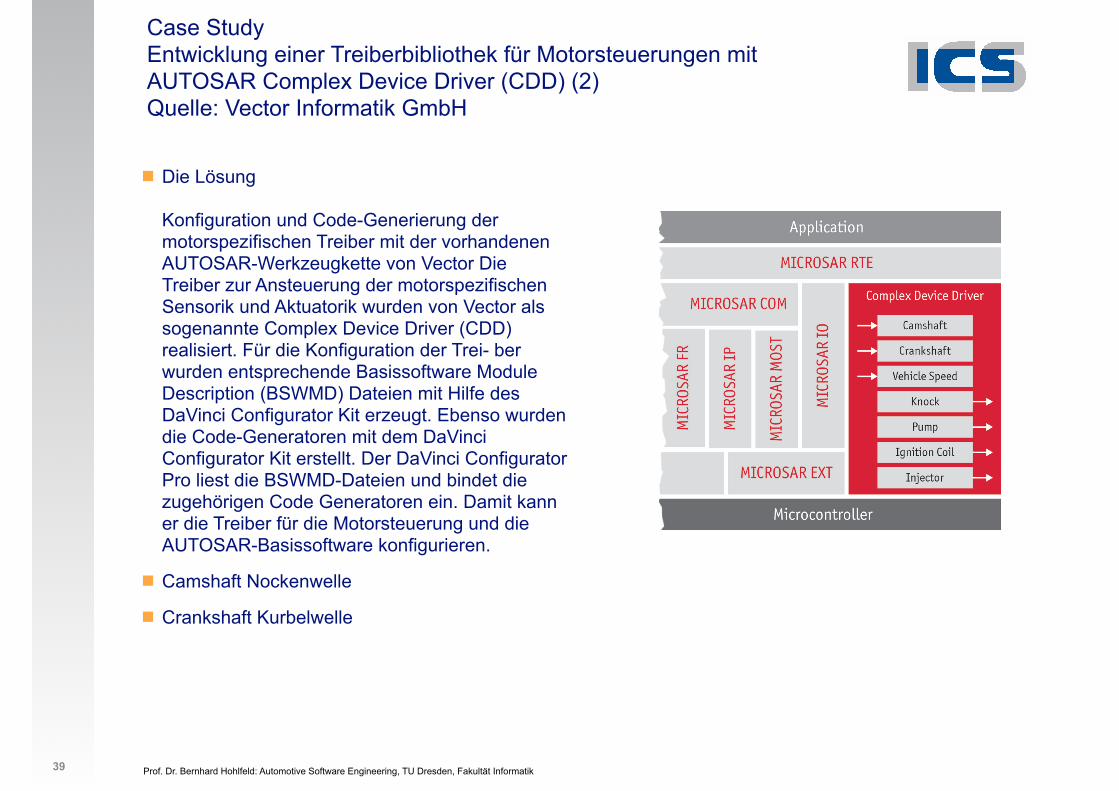
! Die LösungKonfiguration und Code-Generierung der motorspezifischen Treiber mit der vorhandenen AUTOSAR-Werkzeugkette von Vector Die Treiber zur Ansteuerung der motorspezifischen Sensorik und Aktuatorik wurden von Vector als sogenannte Complex Device Driver (CDD) realisiert. Für die Konfiguration der Trei- ber wurden entsprechende Basissoftware Module Description (BSWMD) Dateien mit Hilfe des DaVinci Configurator Kit erzeugt. Ebenso wurden die Code-Generatoren mit dem DaVinci Configurator Kit erstellt. Der DaVinci Configurator Pro liest die BSWMD-Dateien und bindet die zugehörigen Code Generatoren ein. Damit kann er die Treiber für die Motorsteuerung und die AUTOSAR-Basissoftware konfigurieren.
! Camshaft Nockenwelle
! Crankshaft Kurbelwelle
39
Der KundeDie FAW Group Cooperation, die „First Automotive Works“, mit Sitz in Changchun ist der größte chinesische Hersteller von Dieselmotoren, PKWs, sowie mittleren bis schweren Bussen und LKWs. FAW produziert mehr als 2,5 Millionen Fahrzeuge pro Jahr und gehört zu den ersten chinesischen OEMs, die AUTOSAR einsetzen.
Die HerausforderungEntwicklung einer Treiberbibliothek für Motorsteuerungen mit AUTOSAR Complex Device Driver (CDD)FAW entwickelt eine neue Generation ihrer Motorsteuerungen
und setzt dabei konsequent AUTOSAR-Basissoftware ein. Die
Software wird als eine einzige Plattform realisiert, mit der sich
sowohl Benzin- als auch Dieselmotoren steuern lassen. Da in
AUTOSAR keine entsprechenden Treiber für Motorsteuerun-
gen definiert sind, möchte FAW die benötigten Sensoren und
Aktuatoren aus einer erweiterten AUTOSAR-Treiberbibliotek
auswählen und in der gewünschten Anzahl und Ausprägung
mit Hilfe einer durchgängigen Werkzeugkette konfigurieren.
Die LösungKonfiguration und Code-Generierung der motorspezifi-schen Treiber mit der vorhandenen AUTOSAR-Werkzeug-kette von VectorDie Treiber zur Ansteuerung der motorspezifischen Sensorik
und Aktuatorik wurden von Vector als sogenannte Complex
Device Driver (CDD) realisiert. Für die Konfiguration der Trei-
ber wurden entsprechende Basissoftware Module Description
(BSWMD) Dateien mit Hilfe des DaVinci Configurator Kit er-
zeugt. Ebenso wurden die Code-Generatoren mit dem DaVinci
Configurator Kit erstellt. Der DaVinci Configurator Pro liest die
BSWMD-Dateien und bindet die zugehörigen Code Generatoren
ein. Damit kann er die Treiber für die Motorsteuerung und die
AUTOSAR-Basissoftware konfigurieren.
Die VorteileEine durch FAW erweiterbare domänenspezifische Treiber-bibliothek
Konfiguration und Generierung der gesamten Basissoft ware
mit einem Werkzeug: Sowohl die AUTOSAR-Standardmodule
als auch die speziellen Treiber für die Motorsteu erung wer-
den mit dem DaVinci Configurator Pro konfiguriert.
Die Treiberbibliothek kann mit dem DaVinci Configurator Kit
erweitert oder angepasst werden, z.B. wenn neue Sensoren
oder Aktuatoren eingeführt werden.
Reduzierter Verwaltungsaufwand durch Pflege und Erwei-
terung der Bibliothek in einer zentralen Abteilung. Die ver-
schiedenen Fahrzeugprojekte haben Zugriff auf die zentrale
Bibliothek und konfigurieren sie mit dem DaVinci
Configurator Pro entsprechend ihrer spezifischen Motor-
steuerung.
Der in AUTOSAR vorgegebene Prozess und die Schnittstel-
len werden eingehalten: Die Regelalgorithmen für die
Motorsteuerung werden weiterhin mit Matlab und Simulink
entwickelt und als AUTOSAR-Softwarekomponenten (SWC)
realisiert. Diese sind über die RTE mit der AUTOSAR-Basis-
software und den motorspezifischen Treibern verbunden.
Case StudyEntwicklung einer Treiberbibliothek für Motorsteuerungen mit AUTOSAR
Complex Device Driver (CDD)
V1.0
201
1/05
PES
_CS_
FAW
_CDD
-Mot
ortr
eibe
r_DE
Ihr Ansprechpartner bei Vector: Embedded Sales [email protected]
Prof. Dr. Bernhard Hohlfeld: Automotive Software Engineering, TU Dresden, Fakultät Informatik
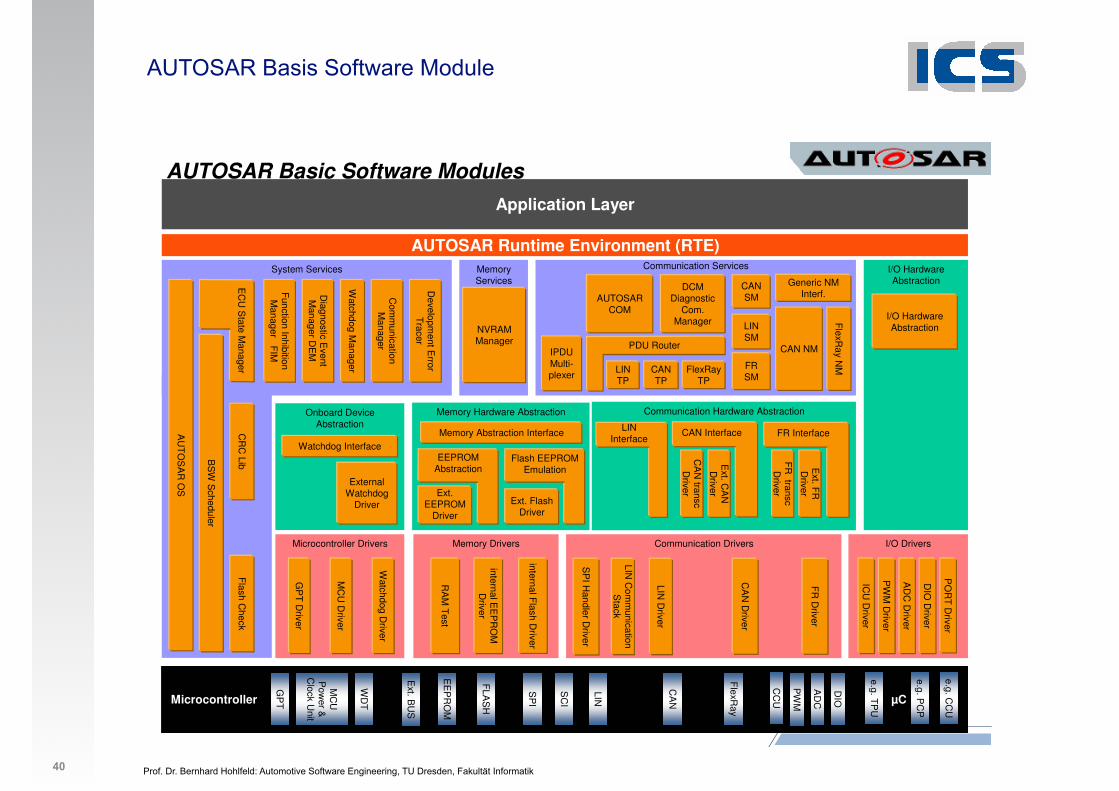
AUTOSAR Basis Software Module
40 20
AUTOSAR Runtime Environment (RTE)
Application Layer
Microcontroller
AD
C
DIO
CC
U
PW
M
LIN
CA
N
SP
I
EE
PR
OM
FLA
SH
WD
T
GP
T
Ext. B
US
MC
U
Pow
er &
Clock U
nit
µC
e.g. CC
U
e.g. PC
P
e.g. TP
U
FlexR
ay
SC
II/O Drivers
PO
RT
Driver
AD
C D
river
DIO
Driver
PW
M D
river
ICU
Driver
Microcontroller Drivers
Watchdog D
river
MC
U D
river
GP
T D
river
Communication Drivers
CA
N D
river
LIN D
river
SP
I Handler D
riverMemory Drivers
RA
M T
est
internal EE
PR
OM
D
river
internal Flash D
river
Communication Services
Generic NM Interf.
FlexR
ay NMFlexRay
TP
DCMDiagnostic
Com.Manager
IPDU Multi-plexer
Communication Hardware Abstraction
Memory Services
NVRAM Manager
CR
C Lib
Flash C
heck
System Services
Function Inhibition M
anager FIM
Watchdog M
anager
Developm
ent Error
Tracer
Diagnostic E
vent M
anager DE
M
AU
TO
SA
R O
S
I/O Hardware Abstraction
Memory Hardware Abstraction
Memory Abstraction Interface
Onboard Device Abstraction
External Watchdog
Driver
CAN NM
CAN TP
Ext. Flash Driver
Flash EEPROM Emulation
FR
Driver
LIN Interface
Ext. C
AN
D
river
CAN InterfaceC
AN
transcD
river
Ext. F
R
Driver
FR Interface
FR
transcD
riverExt. EEPROM
Driver
EEPROM Abstraction
Watchdog Interface
PDU Router
LIN TP
AUTOSAR COM
LIN C
omm
unication S
tack
BS
W S
cheduler
Com
munication
Manager
I/O Hardware Abstraction
AUTOSAR Basic Software Modules
CANSM
LINSM
FRSM
EC
U S
tate Manager
Prof. Dr. Bernhard Hohlfeld: Automotive Software Engineering, TU Dresden, Fakultät Informatik 2
1. Organisation
2. Schichtenmodell
3. Systementwicklung
4. Bussysteme im KFZ
5. Software-Architektur
6. Anwendungsbeispiele
7. Geplante AUTOSAR-Anwendungen
7. Normen und Standards 1. AUTOSAR
41
Prof. Dr. Bernhard Hohlfeld: Automotive Software Engineering, TU Dresden, Fakultät Informatik
Systementwicklung AUTOSAR Software Komponenten (SWC)
Grundsätzlicher Design-Ansatz:
! Trennung zwischen Steuergerät (Infrastruktur) und Anwendung (Funktionalität)
! Eine Anwendung besteht aus miteinander verbundenen Software Komponenten
! Die Software Komponenten sind atomar, d.h. sie können nicht über mehrere Steuergeräte verteilt werden.
! Die Implementierung der Software Komponenten ist unabhängig vom Steuergerät.
! Methodik
! Beispiele
42
Prof. Dr. Bernhard Hohlfeld: Automotive Software Engineering, TU Dresden, Fakultät Informatik
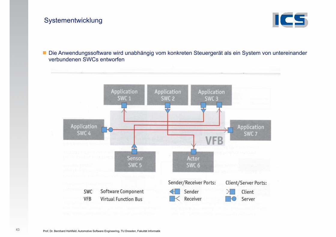
Systementwicklung
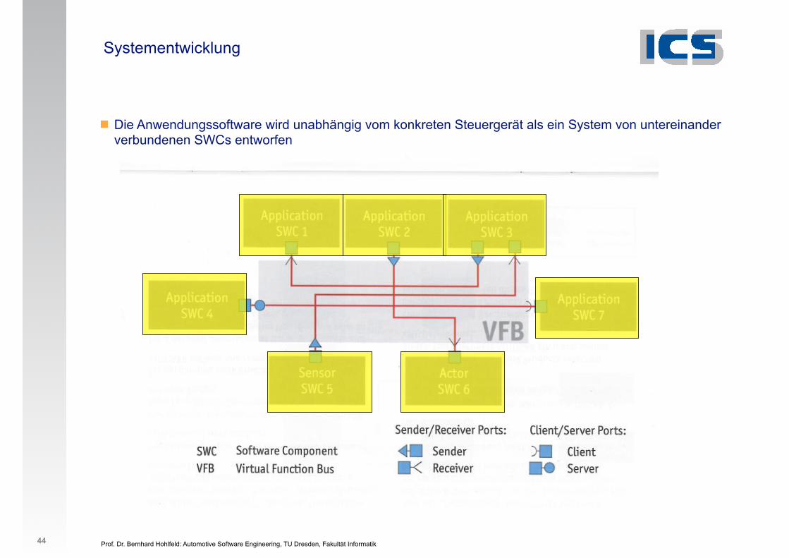
! Die Anwendungssoftware wird unabhängig vom konkreten Steuergerät als ein System von untereinander verbundenen SWCs entworfen
43
Prof. Dr. Bernhard Hohlfeld: Automotive Software Engineering, TU Dresden, Fakultät Informatik
Systementwicklung
! Die Anwendungssoftware wird unabhängig vom konkreten Steuergerät als ein System von untereinander verbundenen SWCs entworfen
44
Prof. Dr. Bernhard Hohlfeld: Automotive Software Engineering, TU Dresden, Fakultät Informatik
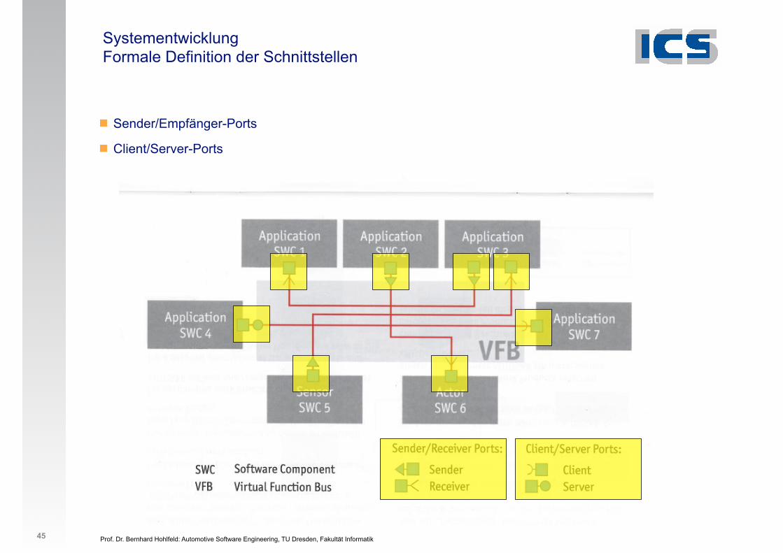
Systementwicklung Formale Definition der Schnittstellen
! Sender/Empfänger-Ports
! Client/Server-Ports
45
Prof. Dr. Bernhard Hohlfeld: Automotive Software Engineering, TU Dresden, Fakultät Informatik
Systementwicklung Sender/Empfänger-Ports
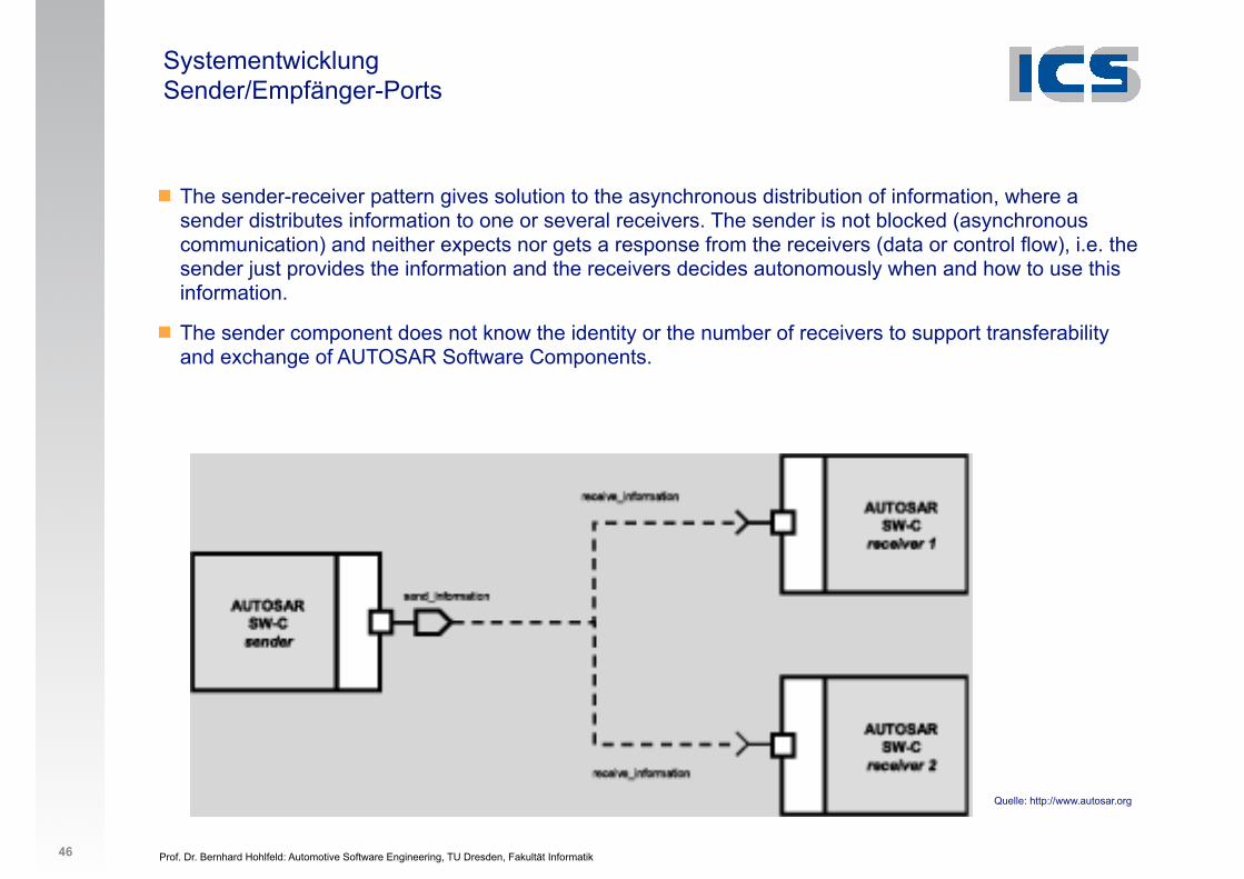
! The sender-receiver pattern gives solution to the asynchronous distribution of information, where a sender distributes information to one or several receivers. The sender is not blocked (asynchronous communication) and neither expects nor gets a response from the receivers (data or control flow), i.e. the sender just provides the information and the receivers decides autonomously when and how to use this information.
! The sender component does not know the identity or the number of receivers to support transferability and exchange of AUTOSAR Software Components.
46
Quelle: http://www.autosar.org
Prof. Dr. Bernhard Hohlfeld: Automotive Software Engineering, TU Dresden, Fakultät Informatik
Systementwicklung Client/Server-Ports
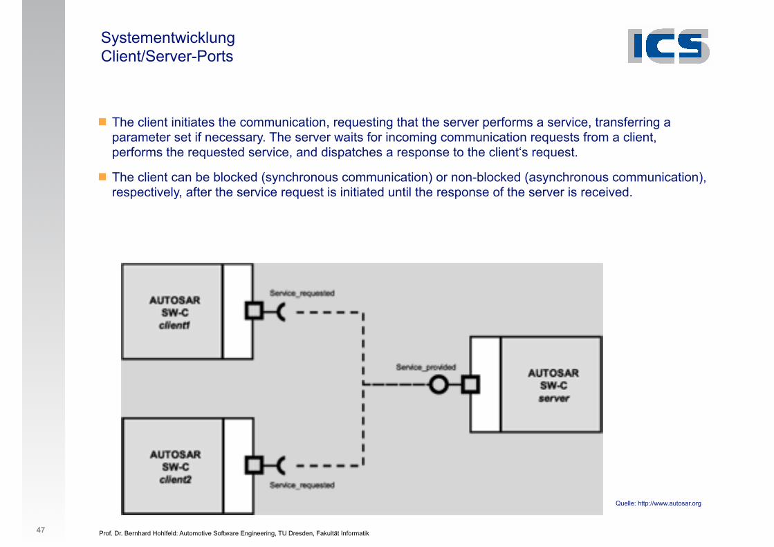
! The client initiates the communication, requesting that the server performs a service, transferring a parameter set if necessary. The server waits for incoming communication requests from a client, performs the requested service, and dispatches a response to the client‘s request.
! The client can be blocked (synchronous communication) or non-blocked (asynchronous communication), respectively, after the service request is initiated until the response of the server is received.
47
Quelle: http://www.autosar.org
Prof. Dr. Bernhard Hohlfeld: Automotive Software Engineering, TU Dresden, Fakultät Informatik
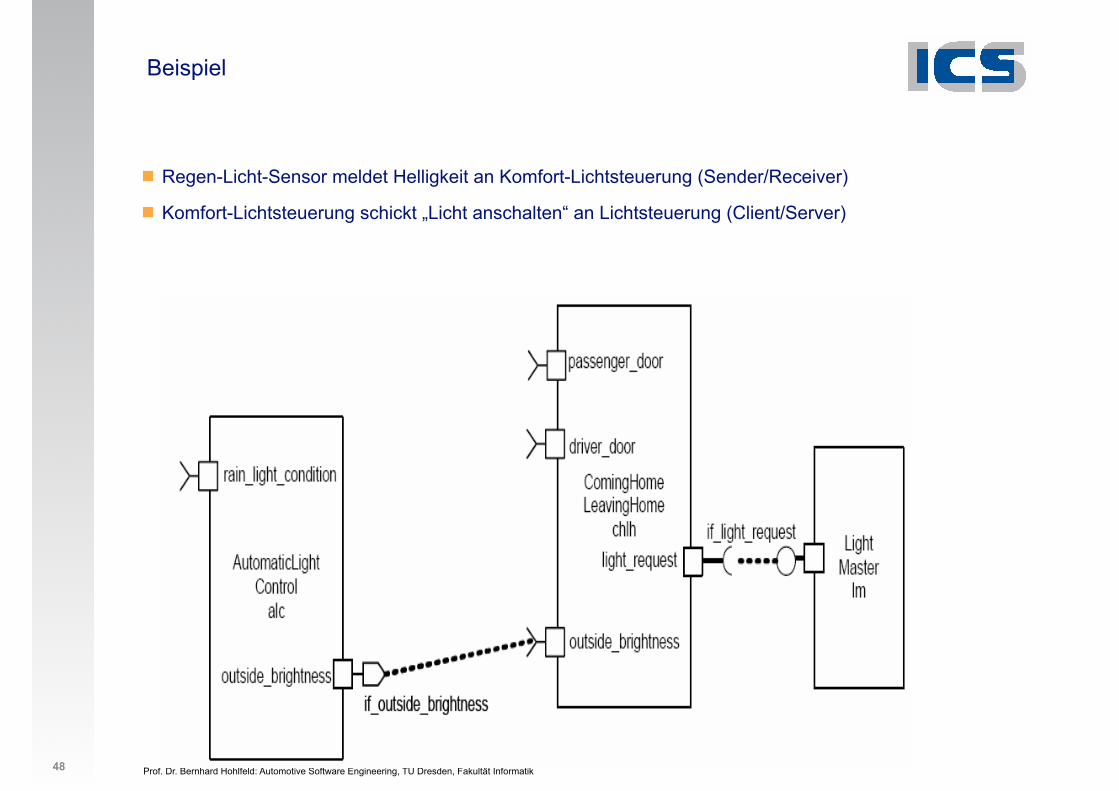
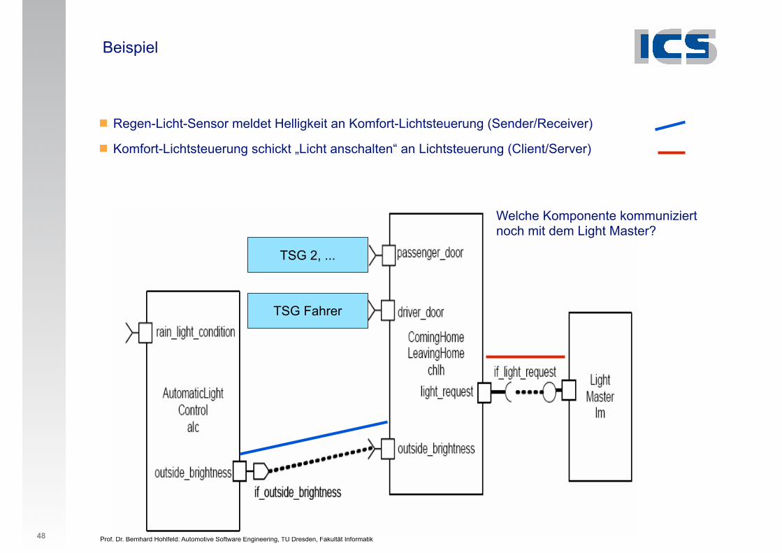
Beispiel
! Regen-Licht-Sensor meldet Helligkeit an Komfort-Lichtsteuerung (Sender/Receiver)
! Komfort-Lichtsteuerung schickt „Licht anschalten“ an Lichtsteuerung (Client/Server)
48
!"#$%!&'%()*+,-.'!-/01*./*2-. 34
!"#$%&'
Prof. Dr. Bernhard Hohlfeld: Automotive Software Engineering, TU Dresden, Fakultät Informatik
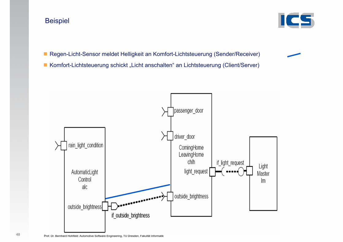
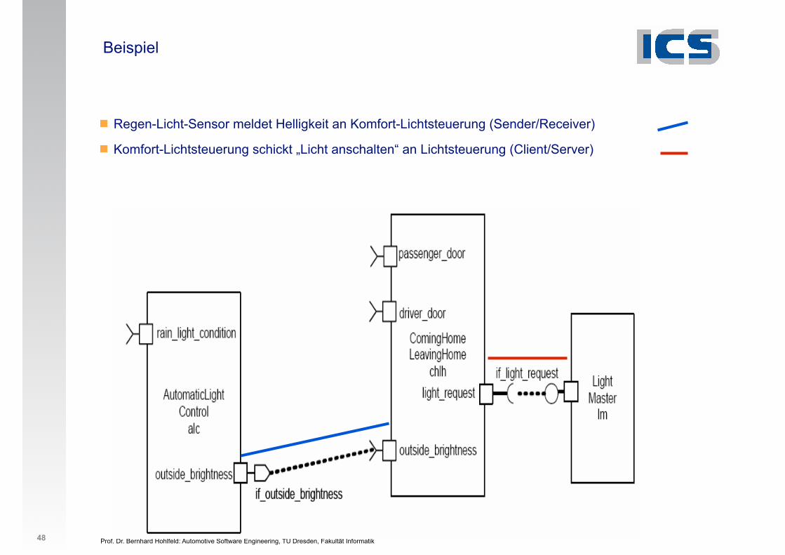
Beispiel
! Regen-Licht-Sensor meldet Helligkeit an Komfort-Lichtsteuerung (Sender/Receiver)
! Komfort-Lichtsteuerung schickt „Licht anschalten“ an Lichtsteuerung (Client/Server)
48
!"#$%!&'%()*+,-.'!-/01*./*2-. 34
!"#$%&'
TSG Fahrer
TSG 2, ...
Prof. Dr. Bernhard Hohlfeld: Automotive Software Engineering, TU Dresden, Fakultät Informatik
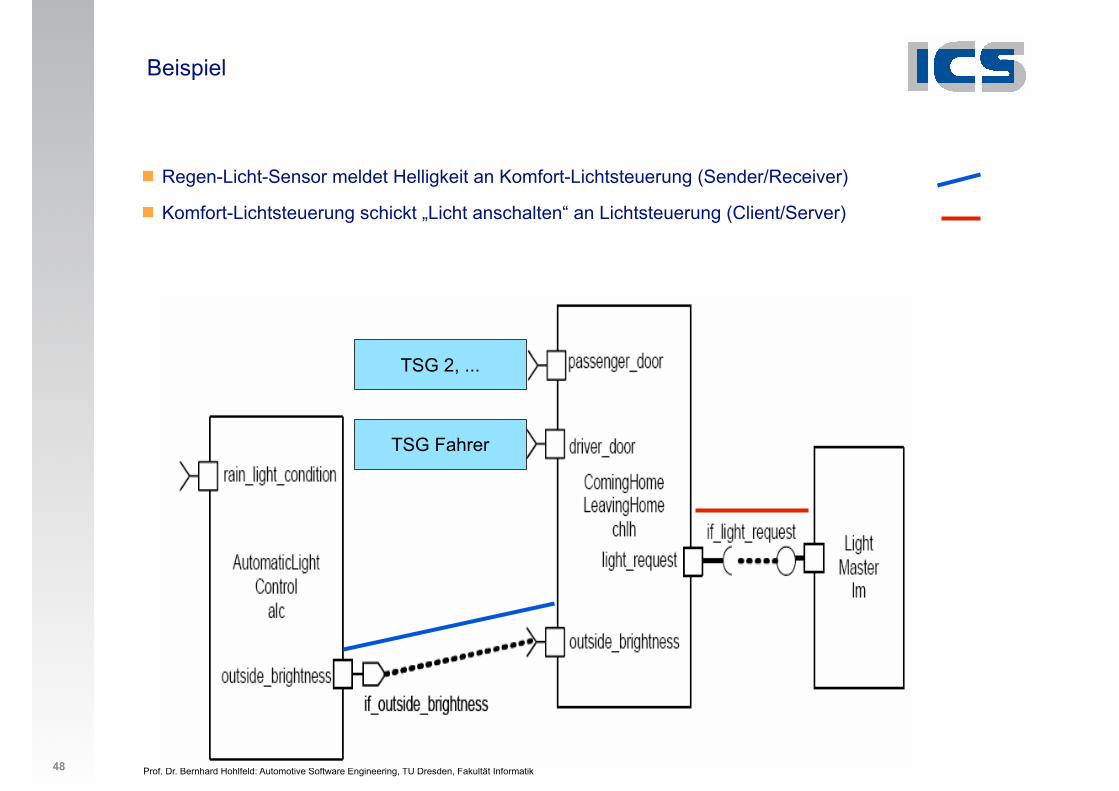
Beispiel
! Regen-Licht-Sensor meldet Helligkeit an Komfort-Lichtsteuerung (Sender/Receiver)
! Komfort-Lichtsteuerung schickt „Licht anschalten“ an Lichtsteuerung (Client/Server)
48
!"#$%!&'%()*+,-.'!-/01*./*2-. 34
!"#$%&'Welche Komponente kommuniziert noch mit dem Light Master?
TSG Fahrer
TSG 2, ...
Prof. Dr. Bernhard Hohlfeld: Automotive Software Engineering, TU Dresden, Fakultät Informatik
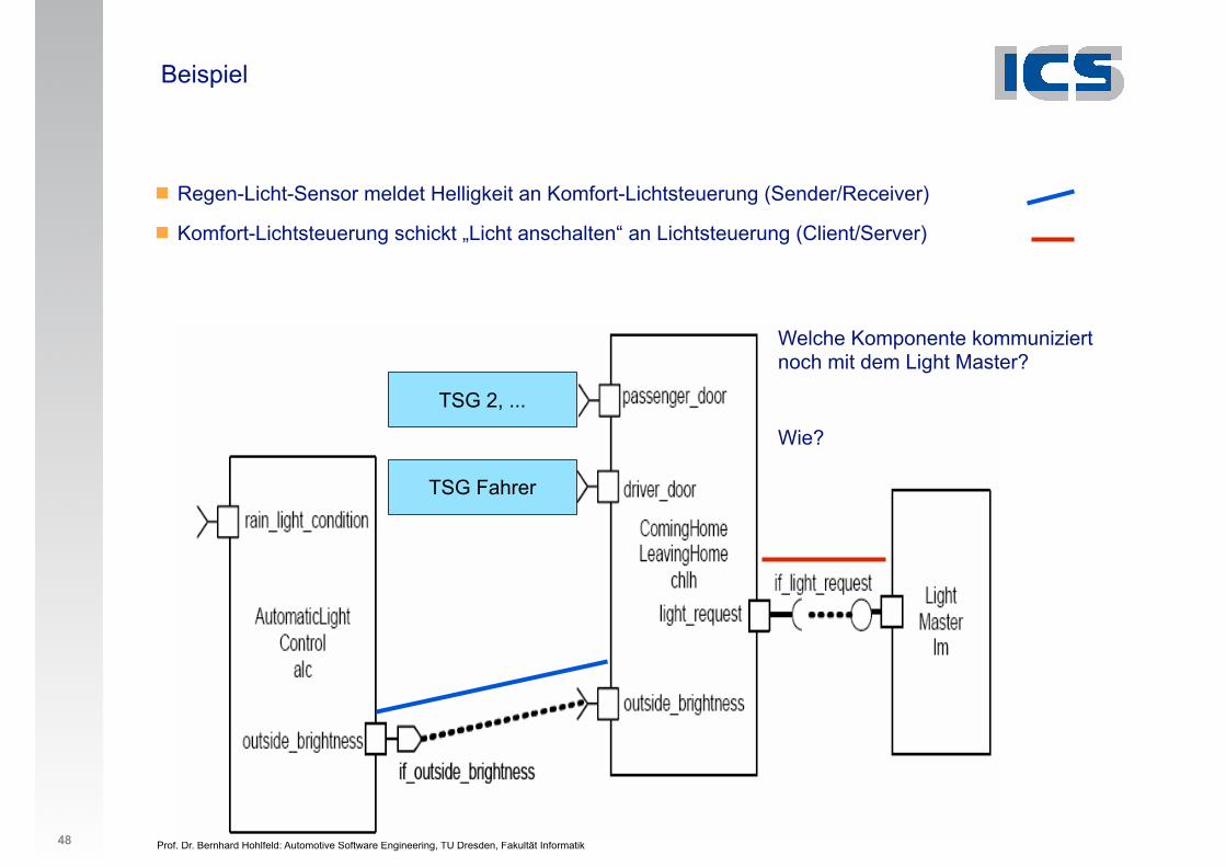
Beispiel
! Regen-Licht-Sensor meldet Helligkeit an Komfort-Lichtsteuerung (Sender/Receiver)
! Komfort-Lichtsteuerung schickt „Licht anschalten“ an Lichtsteuerung (Client/Server)
48
!"#$%!&'%()*+,-.'!-/01*./*2-. 34
!"#$%&'Welche Komponente kommuniziert noch mit dem Light Master?
Wie?
TSG Fahrer
TSG 2, ...

Prof. Dr. Bernhard Hohlfeld: Automotive Software Engineering, TU Dresden, Fakultät Informatik
Weitere Informationen zu Ports
! Dr. Stefan Bunzel – AUTOSAR Spokesperson (Continental): Hardware-independent Software Development with AUTOSAR8. Workshop Automotive Software Engineering30 September, 2010, Leipzig
! O. Kindel, M. Friedrich: Softwareentwicklung mit AUTOSAR. Grundlagen, Engineering, Management für die Praxis. dpunkt.verlag, 2009
!! Insgesamt 2 x 5 = 10 verschiedene Typen von Ports
! PPort: Provides Interface, Data, Service
! RPort: Requires Interface, Data, Service
! Sender-Receiver Interface
! Client-Server Interface
! Calibration Interface
! Data of AUTOSAR Service
! AUTOSAR Service
49
✔
Prof. Dr. Bernhard Hohlfeld: Automotive Software Engineering, TU Dresden, Fakultät Informatik
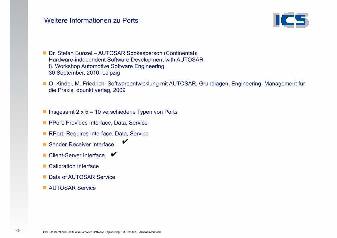
Weitere Informationen zu Ports
! Dr. Stefan Bunzel – AUTOSAR Spokesperson (Continental): Hardware-independent Software Development with AUTOSAR8. Workshop Automotive Software Engineering30 September, 2010, Leipzig
! O. Kindel, M. Friedrich: Softwareentwicklung mit AUTOSAR. Grundlagen, Engineering, Management für die Praxis. dpunkt.verlag, 2009
!! Insgesamt 2 x 5 = 10 verschiedene Typen von Ports
! PPort: Provides Interface, Data, Service
! RPort: Requires Interface, Data, Service
! Sender-Receiver Interface
! Client-Server Interface
! Calibration Interface
! Data of AUTOSAR Service
! AUTOSAR Service
49
✔
✔
Prof. Dr. Bernhard Hohlfeld: Automotive Software Engineering, TU Dresden, Fakultät Informatik 50
AUTOSAR Development Methodology Virtual Functional Bus Concept
Prof. Dr. Bernhard Hohlfeld: Automotive Software Engineering, TU Dresden, Fakultät Informatik 50
AUTOSAR Development Methodology Virtual Functional Bus Concept
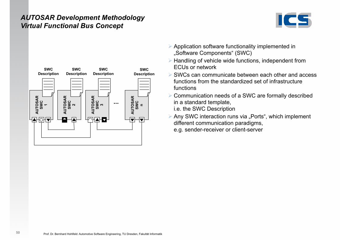
" Application software functionality implemented in „Software Components“ (SWC)
Prof. Dr. Bernhard Hohlfeld: Automotive Software Engineering, TU Dresden, Fakultät Informatik 50
...
AU
TOSA
R
SWC
n
AU
TOSA
R
SWC
3
AU
TOSA
R
SWC
2
AU
TOSA
R
SWC
1
AUTOSAR Development Methodology Virtual Functional Bus Concept
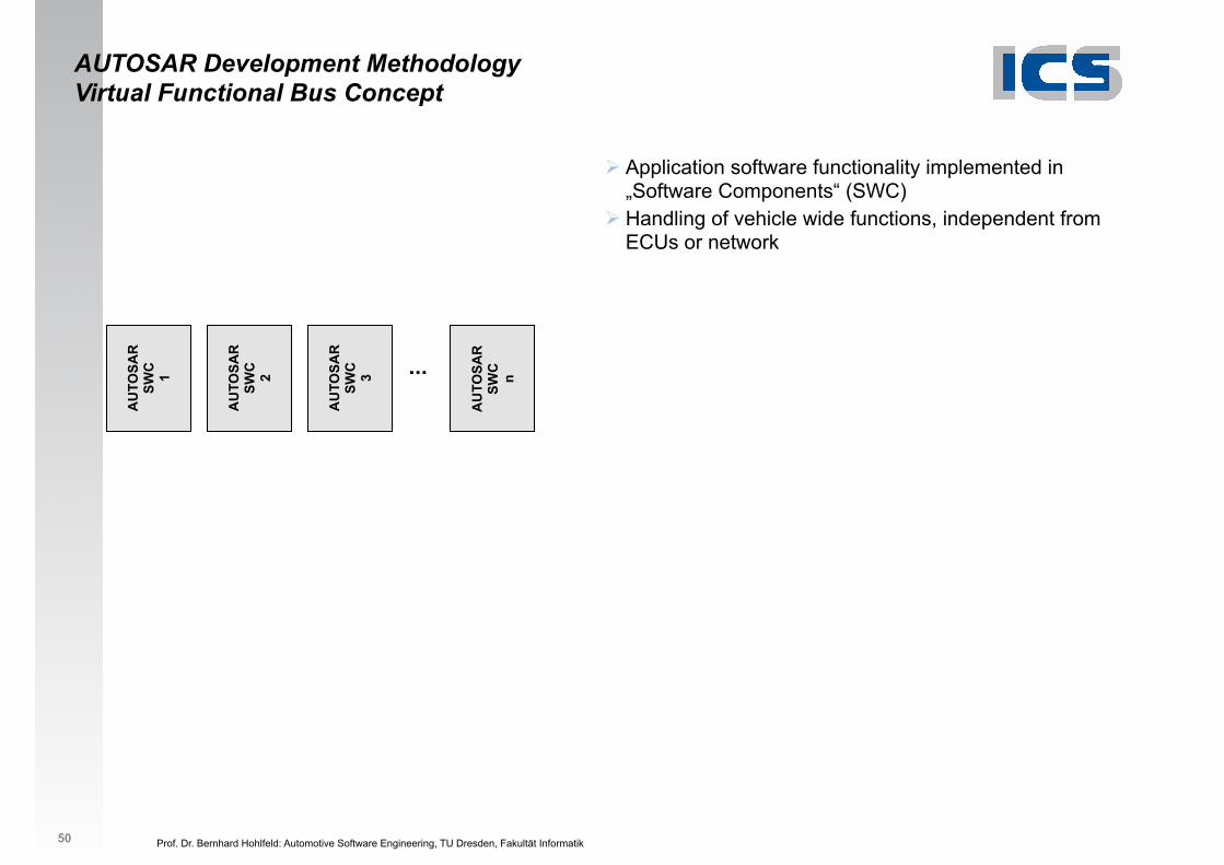
" Application software functionality implemented in „Software Components“ (SWC)
" Handling of vehicle wide functions, independent from ECUs or network
Prof. Dr. Bernhard Hohlfeld: Automotive Software Engineering, TU Dresden, Fakultät Informatik 50
...
AU
TOSA
R
SWC
n
AU
TOSA
R
SWC
3
AU
TOSA
R
SWC
2
AU
TOSA
R
SWC
1
AUTOSAR Development Methodology Virtual Functional Bus Concept
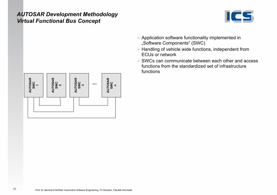
" Application software functionality implemented in „Software Components“ (SWC)
" Handling of vehicle wide functions, independent from ECUs or network
" SWCs can communicate between each other and access functions from the standardized set of infrastructure functions
Prof. Dr. Bernhard Hohlfeld: Automotive Software Engineering, TU Dresden, Fakultät Informatik 50
...
AU
TOSA
R
SWC
n
AU
TOSA
R
SWC
3
AU
TOSA
R
SWC
2
AU
TOSA
R
SWC
1
AUTOSAR Development Methodology Virtual Functional Bus Concept
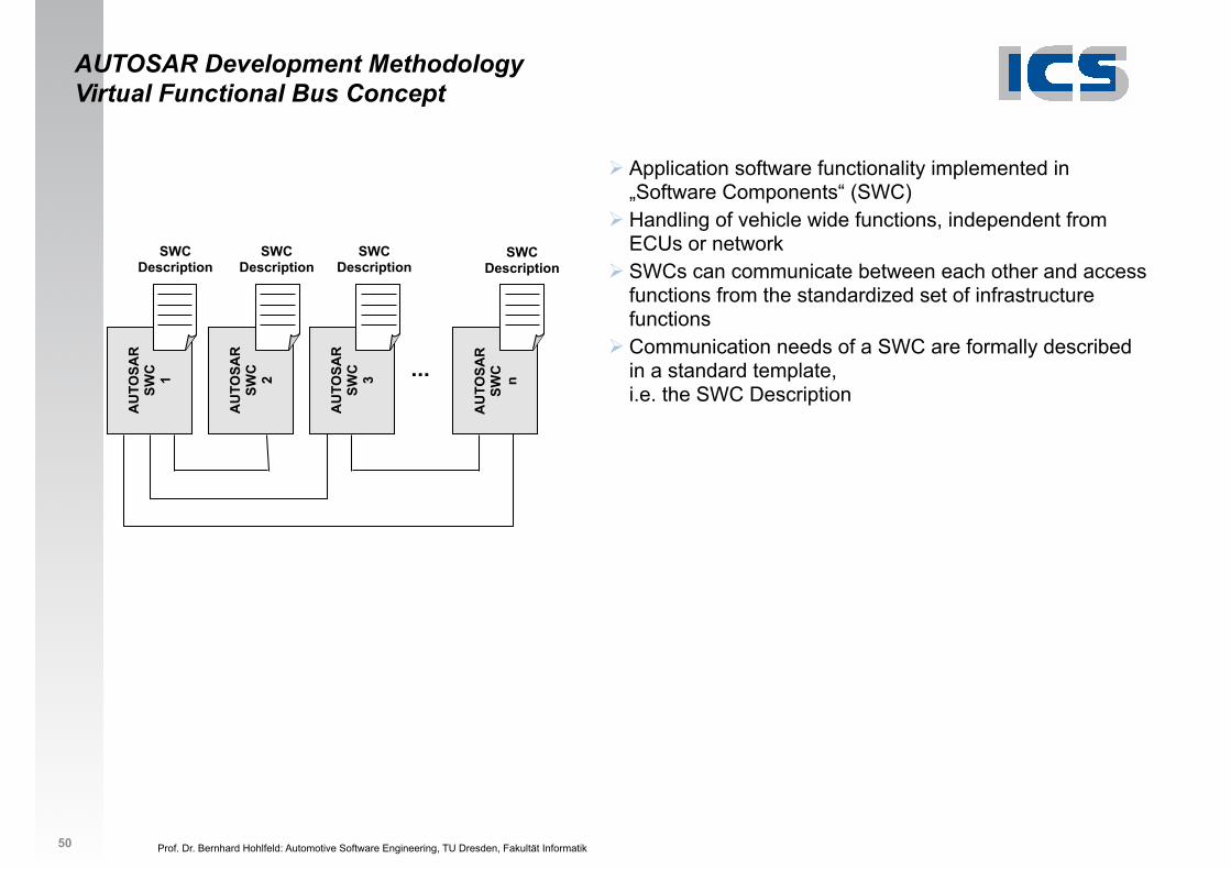
" Application software functionality implemented in „Software Components“ (SWC)
" Handling of vehicle wide functions, independent from ECUs or network
" SWCs can communicate between each other and access functions from the standardized set of infrastructure functions
" Communication needs of a SWC are formally described in a standard template, i.e. the SWC Description
SWC Description
SWC Description
SWC Description
SWC Description
Prof. Dr. Bernhard Hohlfeld: Automotive Software Engineering, TU Dresden, Fakultät Informatik 50
...
AU
TOSA
R
SWC
n
AU
TOSA
R
SWC
3
AU
TOSA
R
SWC
2
AU
TOSA
R
SWC
1
AUTOSAR Development Methodology Virtual Functional Bus Concept
" Application software functionality implemented in „Software Components“ (SWC)
" Handling of vehicle wide functions, independent from ECUs or network
" SWCs can communicate between each other and access functions from the standardized set of infrastructure functions
" Communication needs of a SWC are formally described in a standard template, i.e. the SWC Description
" Any SWC interaction runs via „Ports“, which implement different communication paradigms, e.g. sender-receiver or client-server
SWC Description
SWC Description
SWC Description
SWC Description
Prof. Dr. Bernhard Hohlfeld: Automotive Software Engineering, TU Dresden, Fakultät Informatik 50
Virtual Functional Bus
...
AU
TOSA
R
SWC
n
AU
TOSA
R
SWC
3
AU
TOSA
R
SWC
2
AU
TOSA
R
SWC
1
AUTOSAR Development Methodology Virtual Functional Bus Concept
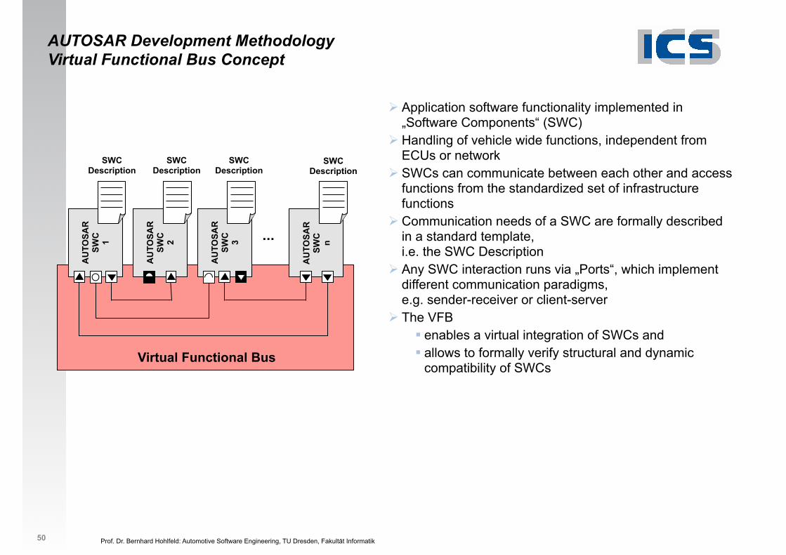
" Application software functionality implemented in „Software Components“ (SWC)
" Handling of vehicle wide functions, independent from ECUs or network
" SWCs can communicate between each other and access functions from the standardized set of infrastructure functions
" Communication needs of a SWC are formally described in a standard template, i.e. the SWC Description
" Any SWC interaction runs via „Ports“, which implement different communication paradigms, e.g. sender-receiver or client-server
" The VFB # enables a virtual integration of SWCs and# allows to formally verify structural and dynamic
compatibility of SWCs
SWC Description
SWC Description
SWC Description
SWC Description
Prof. Dr. Bernhard Hohlfeld: Automotive Software Engineering, TU Dresden, Fakultät Informatik 51
AU
TOSA
R S
WC
Virtual Functional Bus
...
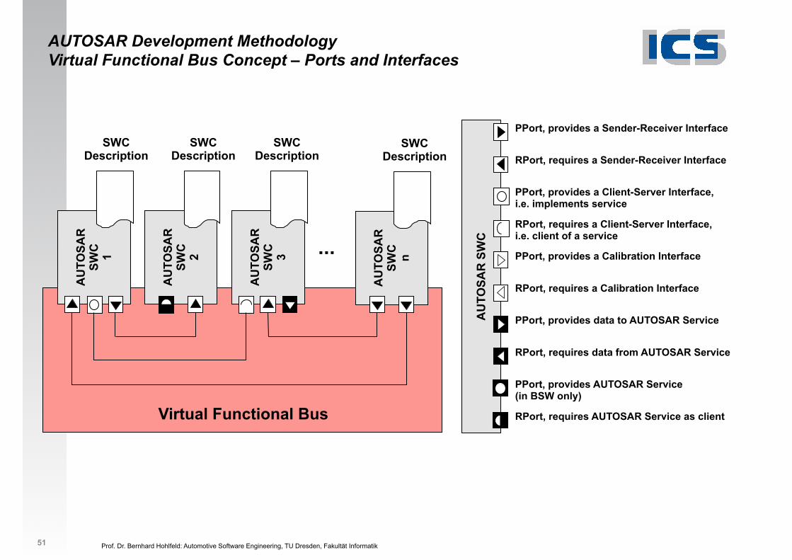
PPort, provides a Sender-Receiver Interface
RPort, requires a Sender-Receiver Interface
PPort, provides a Client-Server Interface, i.e. implements service
RPort, requires a Client-Server Interface, i.e. client of a service
PPort, provides data to AUTOSAR Service
PPort, provides AUTOSAR Service (in BSW only)
AU
TOSA
R
SWC
n
SWC Description
PPort, provides a Calibration Interface
RPort, requires a Calibration Interface
RPort, requires AUTOSAR Service as client
RPort, requires data from AUTOSAR Service
AU
TOSA
R
SWC
3
SWC Description
AU
TOSA
R
SWC
2
SWC Description
AU
TOSA
R
SWC
1
SWC Description
AUTOSAR Development Methodology Virtual Functional Bus Concept – Ports and Interfaces
Prof. Dr. Bernhard Hohlfeld: Automotive Software Engineering, TU Dresden, Fakultät Informatik
Systementwicklung Virtual Function Bus (VFB)
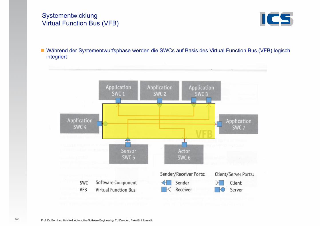
! Während der Systementwurfsphase werden die SWCs auf Basis des Virtual Function Bus (VFB) logisch integriert
52
Prof. Dr. Bernhard Hohlfeld: Automotive Software Engineering, TU Dresden, Fakultät Informatik
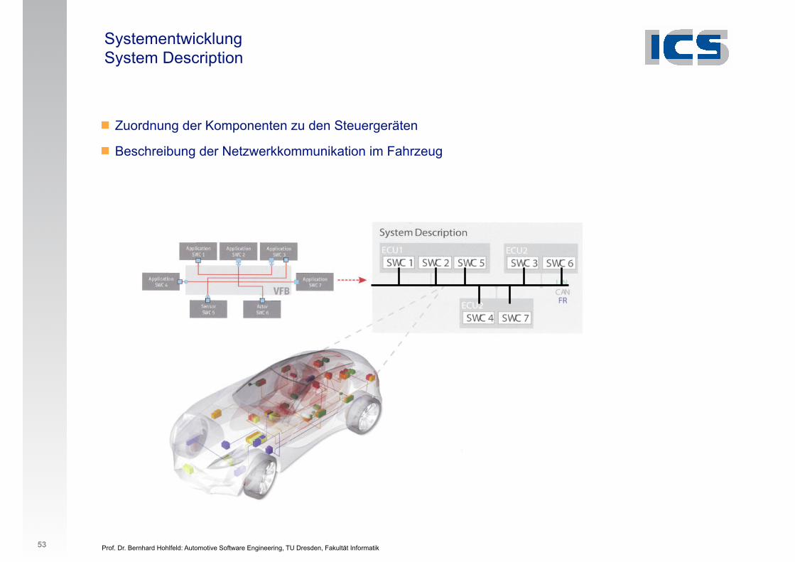
Systementwicklung System Description
! Zuordnung der Komponenten zu den Steuergeräten
! Beschreibung der Netzwerkkommunikation im Fahrzeug
53
Prof. Dr. Bernhard Hohlfeld: Automotive Software Engineering, TU Dresden, Fakultät Informatik
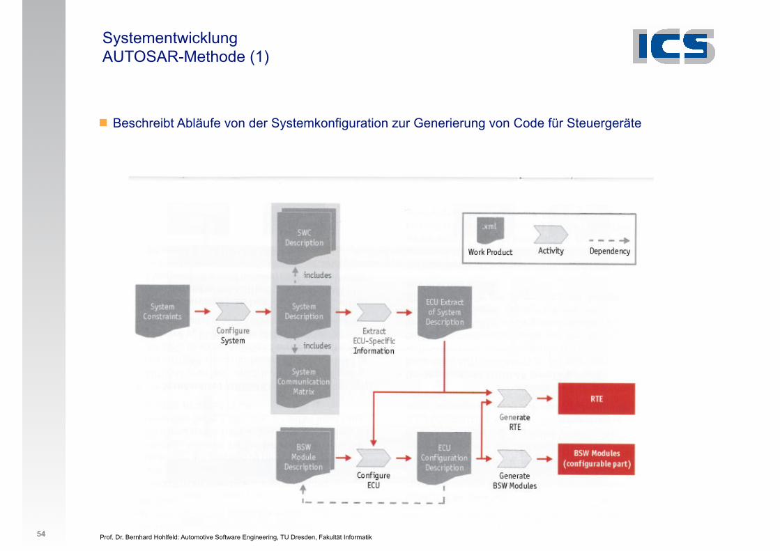
Systementwicklung AUTOSAR-Methode (1)
! Beschreibt Abläufe von der Systemkonfiguration zur Generierung von Code für Steuergeräte
54
Prof. Dr. Bernhard Hohlfeld: Automotive Software Engineering, TU Dresden, Fakultät Informatik
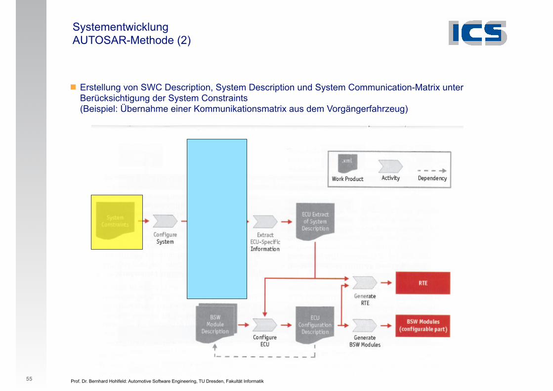
Systementwicklung AUTOSAR-Methode (2)
! Erstellung von SWC Description, System Description und System Communication-Matrix unter Berücksichtigung der System Constraints (Beispiel: Übernahme einer Kommunikationsmatrix aus dem Vorgängerfahrzeug)
55
Prof. Dr. Bernhard Hohlfeld: Automotive Software Engineering, TU Dresden, Fakultät Informatik
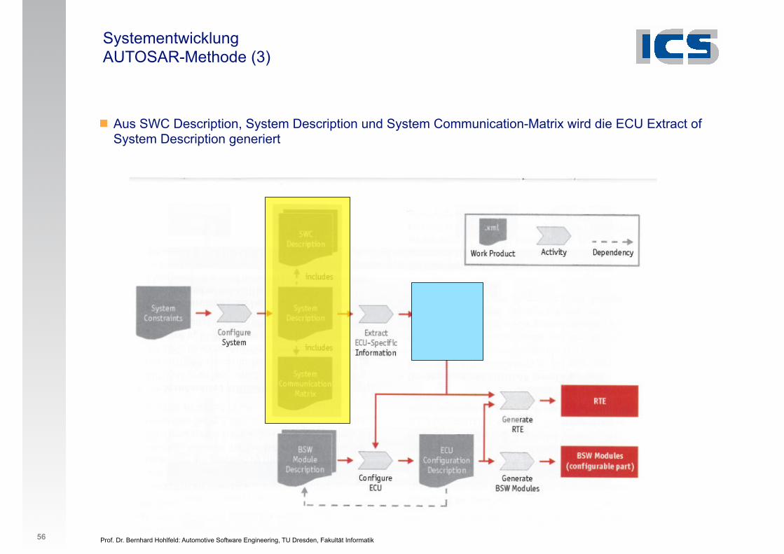
Systementwicklung AUTOSAR-Methode (3)
! Aus SWC Description, System Description und System Communication-Matrix wird die ECU Extract of System Description generiert
56
Prof. Dr. Bernhard Hohlfeld: Automotive Software Engineering, TU Dresden, Fakultät Informatik
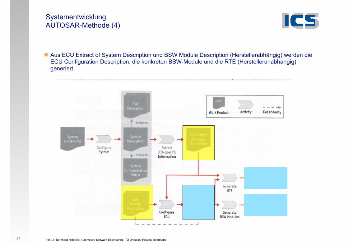
Systementwicklung AUTOSAR-Methode (4)
! Aus ECU Extract of System Description und BSW Module Description (Herstellerabhängig) werden die ECU Configuration Description, die konkreten BSW-Module und die RTE (Herstellerunabhängig) generiert
57
Prof. Dr. Bernhard Hohlfeld: Automotive Software Engineering, TU Dresden, Fakultät Informatik
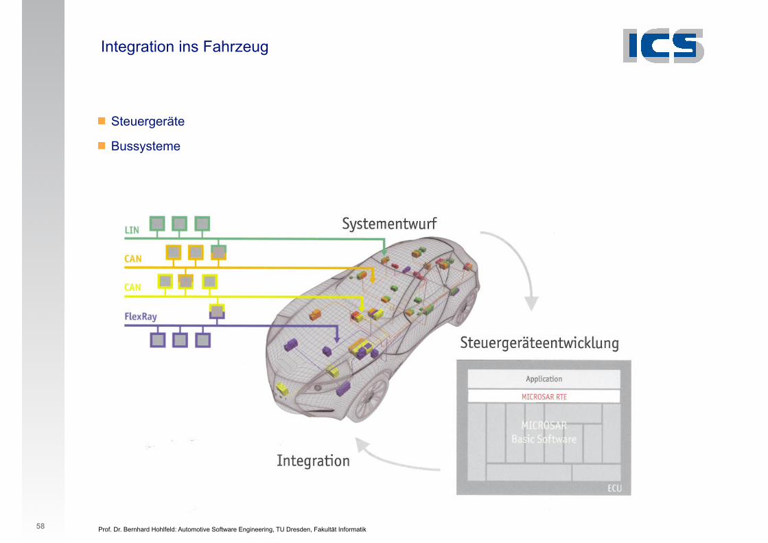
Integration ins Fahrzeug
! Steuergeräte
! Bussysteme
58

Prof. Dr. Bernhard Hohlfeld: Automotive Software Engineering, TU Dresden, Fakultät Informatik 2
1. Organisation
2. Schichtenmodell
3. Systementwicklung
4. Bussysteme im KFZ
5. Software-Architektur
6. Anwendungsbeispiele
7. Geplante AUTOSAR-Anwendungen
7. Normen und Standards 1. AUTOSAR
59
Prof. Dr. Bernhard Hohlfeld: Automotive Software Engineering, TU Dresden, Fakultät Informatik
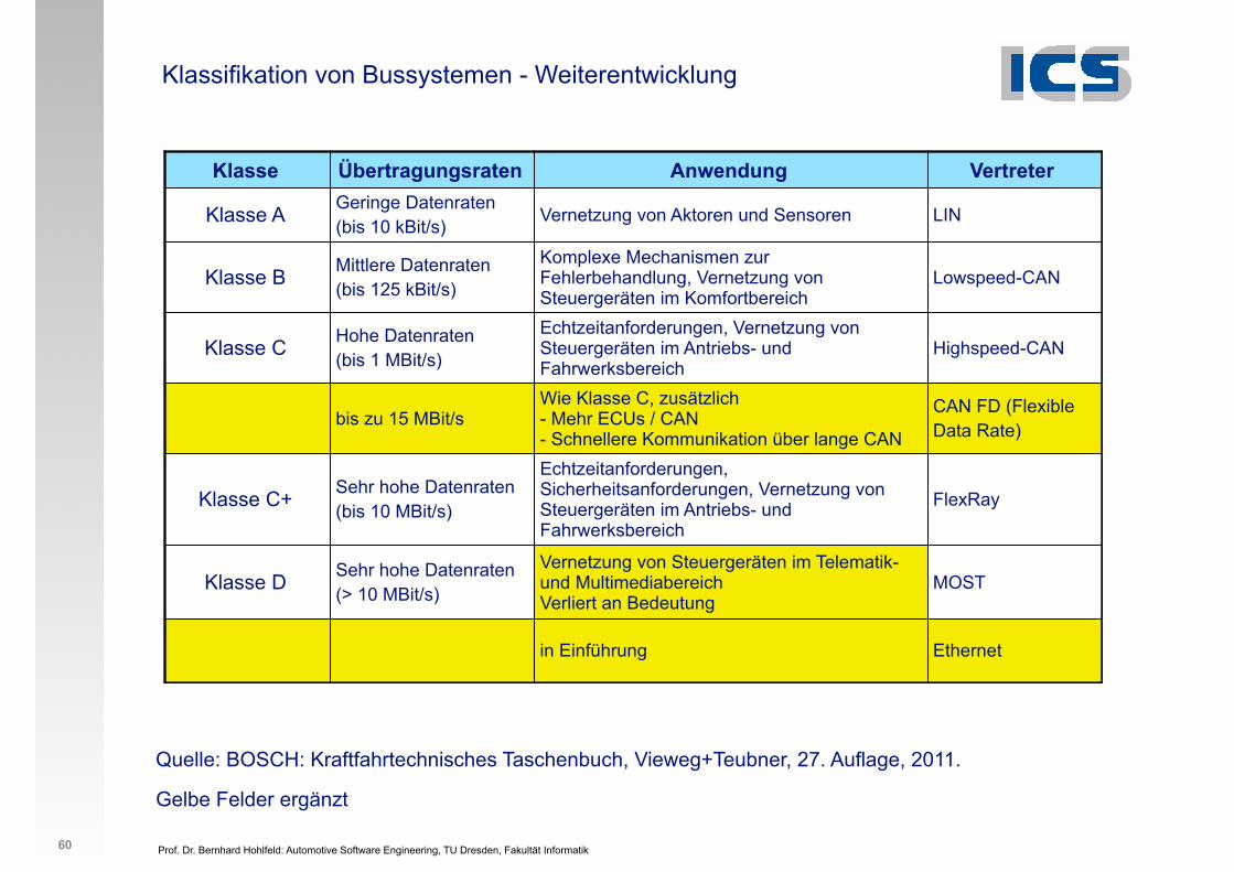
Klassifikation von Bussystemen - Weiterentwicklung
Quelle: BOSCH: Kraftfahrtechnisches Taschenbuch, Vieweg+Teubner, 27. Auflage, 2011.
Gelbe Felder ergänzt
60
Klasse Übertragungsraten Anwendung Vertreter
Klasse A Geringe Datenraten (bis 10 kBit/s) Vernetzung von Aktoren und Sensoren LIN
Klasse B Mittlere Datenraten (bis 125 kBit/s)
Komplexe Mechanismen zur Fehlerbehandlung, Vernetzung von Steuergeräten im Komfortbereich
Lowspeed-CAN
Klasse C Hohe Datenraten (bis 1 MBit/s)
Echtzeitanforderungen, Vernetzung von Steuergeräten im Antriebs- und Fahrwerksbereich
Highspeed-CAN
bis zu 15 MBit/sWie Klasse C, zusätzlich - Mehr ECUs / CAN - Schnellere Kommunikation über lange CAN
CAN FD (Flexible Data Rate)
Klasse C+ Sehr hohe Datenraten (bis 10 MBit/s)
Echtzeitanforderungen, Sicherheitsanforderungen, Vernetzung von Steuergeräten im Antriebs- und Fahrwerksbereich
FlexRay
Klasse D Sehr hohe Datenraten (> 10 MBit/s)
Vernetzung von Steuergeräten im Telematik- und MultimediabereichVerliert an Bedeutung
MOST
in Einführung Ethernet
Prof. Dr. Bernhard Hohlfeld: Automotive Software Engineering, TU Dresden, Fakultät Informatik
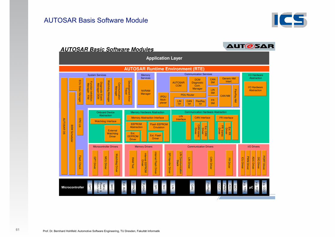
AUTOSAR Basis Software Module
61
20
AUTOSAR Runtime Environment (RTE)
Application Layer
Microcontroller
AD
C
DIO
CC
U
PW
M
LIN
CA
N
SP
I
EE
PR
OM
FLA
SH
WD
T
GP
T
Ext. B
US
MC
U
Pow
er &
Clock U
nit
µC
e.g. CC
U
e.g. PC
P
e.g. TP
U
FlexR
ay
SC
I
I/O Drivers
PO
RT
Driver
AD
C D
river
DIO
Driver
PW
M D
river
ICU
Driver
Microcontroller Drivers
Watchdog D
river
MC
U D
river
GP
T D
river
Communication Drivers
CA
N D
river
LIN D
river
SP
I Handler D
river
Memory Drivers
RA
M T
est
internal EE
PR
OM
D
river
internal Flash D
river
Communication Services
Generic NM Interf.
FlexR
ay NMFlexRay
TP
DCMDiagnostic
Com.Manager
IPDU Multi-plexer
Communication Hardware Abstraction
Memory Services
NVRAM Manager
CR
C Lib
Flash C
heck
System Services
Function Inhibition M
anager FIM
Watchdog M
anager
Developm
ent Error
Tracer
Diagnostic E
vent M
anager DE
M
AU
TO
SA
R O
S
I/O Hardware Abstraction
Memory Hardware Abstraction
Memory Abstraction Interface
Onboard Device Abstraction
External Watchdog
Driver
CAN NM
CAN TP
Ext. Flash Driver
Flash EEPROM Emulation
FR
Driver
LIN Interface
Ext. C
AN
D
river
CAN Interface
CA
N transc
Driver
Ext. F
R
Driver
FR Interface
FR
transcD
riverExt. EEPROM
Driver
EEPROM Abstraction
Watchdog Interface
PDU Router
LIN TP
AUTOSAR COM
LIN C
omm
unication S
tack
BS
W S
cheduler
Com
munication
Manager
I/O Hardware Abstraction
AUTOSAR Basic Software Modules
CANSM
LINSM
FRSM
EC
U S
tate Manager
Prof. Dr. Bernhard Hohlfeld: Automotive Software Engineering, TU Dresden, Fakultät Informatik
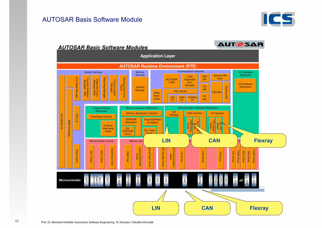
AUTOSAR Basis Software Module
62
20
AUTOSAR Runtime Environment (RTE)
Application Layer
Microcontroller
AD
C
DIO
CC
U
PW
M
LIN
CA
N
SP
I
EE
PR
OM
FLA
SH
WD
T
GP
T
Ext. B
US
MC
U
Pow
er &
Clock U
nit
µC
e.g. CC
U
e.g. PC
P
e.g. TP
U
FlexR
ay
SC
I
I/O Drivers
PO
RT
Driver
AD
C D
river
DIO
Driver
PW
M D
river
ICU
Driver
Microcontroller Drivers
Watchdog D
river
MC
U D
river
GP
T D
river
Communication Drivers
CA
N D
river
LIN D
river
SP
I Handler D
river
Memory Drivers
RA
M T
est
internal EE
PR
OM
D
river
internal Flash D
river
Communication Services
Generic NM Interf.
FlexR
ay NMFlexRay
TP
DCMDiagnostic
Com.Manager
IPDU Multi-plexer
Communication Hardware Abstraction
Memory Services
NVRAM Manager
CR
C Lib
Flash C
heck
System Services
Function Inhibition M
anager FIM
Watchdog M
anager
Developm
ent Error
Tracer
Diagnostic E
vent M
anager DE
M
AU
TO
SA
R O
S
I/O Hardware Abstraction
Memory Hardware Abstraction
Memory Abstraction Interface
Onboard Device Abstraction
External Watchdog
Driver
CAN NM
CAN TP
Ext. Flash Driver
Flash EEPROM Emulation
FR
Driver
LIN Interface
Ext. C
AN
D
river
CAN Interface
CA
N transc
Driver
Ext. F
R
Driver
FR Interface
FR
transcD
riverExt. EEPROM
Driver
EEPROM Abstraction
Watchdog Interface
PDU Router
LIN TP
AUTOSAR COM
LIN C
omm
unication S
tack
BS
W S
cheduler
Com
munication
Manager
I/O Hardware Abstraction
AUTOSAR Basic Software Modules
CANSM
LINSM
FRSM
EC
U S
tate Manager
LIN CAN Flexray
LIN CAN Flexray
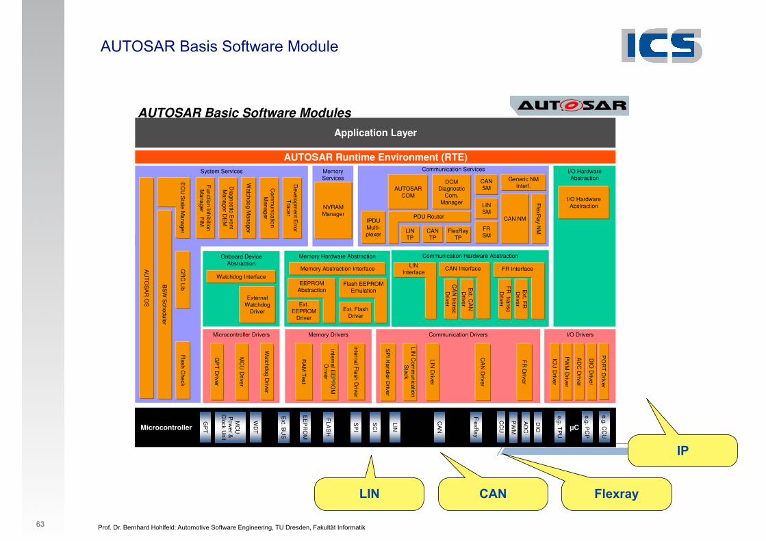
Prof. Dr. Bernhard Hohlfeld: Automotive Software Engineering, TU Dresden, Fakultät Informatik
AUTOSAR Basis Software Module
63
20
AUTOSAR Runtime Environment (RTE)
Application Layer
Microcontroller
AD
C
DIO
CC
U
PW
M
LIN
CA
N
SP
I
EE
PR
OM
FLA
SH
WD
T
GP
T
Ext. B
US
MC
U
Pow
er &
Clock U
nit
µC
e.g. CC
U
e.g. PC
P
e.g. TP
U
FlexR
ay
SC
I
I/O Drivers
PO
RT
Driver
AD
C D
river
DIO
Driver
PW
M D
river
ICU
Driver
Microcontroller Drivers
Watchdog D
river
MC
U D
river
GP
T D
river
Communication Drivers
CA
N D
river
LIN D
river
SP
I Handler D
river
Memory Drivers
RA
M T
est
internal EE
PR
OM
D
river
internal Flash D
river
Communication Services
Generic NM Interf.
FlexR
ay NMFlexRay
TP
DCMDiagnostic
Com.Manager
IPDU Multi-plexer
Communication Hardware Abstraction
Memory Services
NVRAM Manager
CR
C Lib
Flash C
heck
System Services
Function Inhibition M
anager FIM
Watchdog M
anager
Developm
ent Error
Tracer
Diagnostic E
vent M
anager DE
M
AU
TO
SA
R O
S
I/O Hardware Abstraction
Memory Hardware Abstraction
Memory Abstraction Interface
Onboard Device Abstraction
External Watchdog
Driver
CAN NM
CAN TP
Ext. Flash Driver
Flash EEPROM Emulation
FR
Driver
LIN Interface
Ext. C
AN
D
river
CAN Interface
CA
N transc
Driver
Ext. F
R
Driver
FR Interface
FR
transcD
riverExt. EEPROM
Driver
EEPROM Abstraction
Watchdog Interface
PDU Router
LIN TP
AUTOSAR COM
LIN C
omm
unication S
tack
BS
W S
cheduler
Com
munication
Manager
I/O Hardware Abstraction
AUTOSAR Basic Software Modules
CANSM
LINSM
FRSM
EC
U S
tate Manager
LIN CAN Flexray
IP
Prof. Dr. Bernhard Hohlfeld: Automotive Software Engineering, TU Dresden, Fakultät Informatik
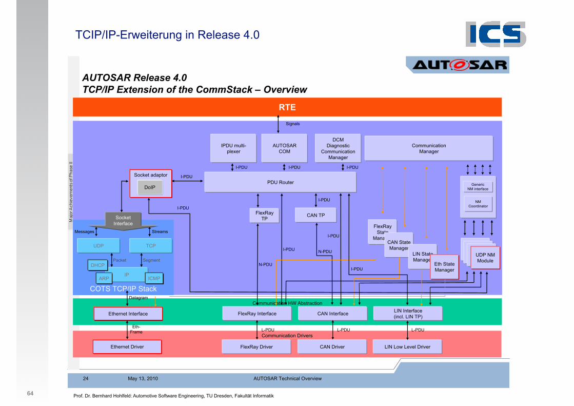
TCIP/IP-Erweiterung in Release 4.0
64
AUTOSAR Release 4.0 TCP/IP Extension of the CommStack – Overview
Communication HW Abstraction
RTE
Communication Drivers
AUTOSAR COM
FlexRay Interface CAN Interface LIN Interface (incl. LIN TP)
N-PDU
Communication Manager
Signals
FlexRay Driver CAN Driver LIN Low Level Driver
FlexRay TP
I-PDU
DCMDiagnostic
Communication Manager
CAN TP
I-PDU
I-PDU
I-PDU
I-PDU
N-PDU
L-PDU L-PDU L-PDU
IPDU multi- plexer
I-PDU
NM Coordinator
GenericNM interface
FlexRayState
Manager
NM Module
CAN State Manager
LIN State Manager
NM ModuleNM
ModuleEth State Manager
UDP NM Module
Socket adaptor
Ethernet Interface
Ethernet Driver
Eth- Frame
COTS TCP/IP Stack
Streams
IP
TCPUDP
Segment
Messages
Packet
ARP ICMP
Socket Interface
Datagram
I-PDU
I-PDU
DHCP
DoIPPDU Router
I-PDU
May 13, 2010 AUTOSAR Technical Overview24