Volvo S40 Manual
226
2005 S40 VOLVO WEB EDITION
-
Upload
jiannis-kouts -
Category
Documents
-
view
309 -
download
1
Transcript of Volvo S40 Manual

2005
S40VOLVO
20
05
6968TP
OW
NE
R'S
MA
NU
AL
VO
LVO
S4
0
7459 (English). AT 0446. Printed in Sweden, Elanders Infologistics Väst AB, Mölnlycke 2004
TP
74
59 WEB EDITION

N
Int
DeWe r the safety and comfort of you and yourpas isfy all current safety and environmentalreq
In o equipment, instructions and maintenanceinfo
Tha
Int
roductionar Volvo ownerhope you will enjoy many years of driving pleasure in your Volvo. The car has been designed fo
sengers. Volvo is one of the safest cars in the world. Your Volvo has also been designed to satuirements.
rder to increase your enjoyment of the car, we recommend that you familiarise yourself with thermation contained in this owner’s manual.
nk you for choosing Volvo!
roduction

O
Introduction
OwA gis tyoutuntionfereall tthema
Themationdesand
NOreq
"Wrisin
Im"Idain
ner’s Manualood way of getting to know your new caro read the owner’s manual, ideally beforer first journey. This will give you the oppor-ity to familiarise yourself with new func-s, to see how best to handle the car in dif-nt situations, and to make the best use ofhe car’s features. Please pay attention tosafety instructions contained in the
nual:
equipment described in the owner’snual is not present in all models. In addi-
to standard equipment, this manual alsocribes options (factory fitted equipment)certain accessories (extra equipment).
TE! Volvo cars are adapted for the varyinguirements of different markets, as well as
for national or local legal requirements andregulations.
The specifications, design features and illus-trations in this owner’s manual are not bind-ing. We reserve the right to make modifica-tions without prior notice.
© Volvo Car Corporation
WARNING!arning!" texts indicate where there is a
k of personal injury in the event of thestructions not being followed.
portant!mportant!" texts indicate a risk ofmage to the car in the event of the
structions not being followed.

P
Volvo Cars and the environment
Vo
OuQutheactwithardcleathemuISOingVolmeenaronandinfo
l of carbon monoxide in the incoming aircloses the air intakes to prevent the levele cabin from becoming too high - for
mple in heavy city traffic, tailbacks andels - while the carbon filter traps nitrogenes, ground-level ozone and hydrocar-s. In addition, to benefit allergy sufferers,fabrics used in the interior comply with
provisions of the international Öko-Tex2
dard. Outside, a special catalytic coating
wn as PremAir®3 is used to convert harm-round-level ozone in the air passingugh the radiator into pure oxygen.
. An international ecological standardfor textiles
. Applies only to five-cylinder enginesPremAir® is a registered trademarkof Engelhard Corporation
lvo Cars and the environment
r environmental philosophyality, Safety and Environmental care arethree core values which guide all the
ivities of Volvo Cars. Volvo cars complystrict international environmental stand-
s and are manufactured in some of thenest and most resource-efficient plants inworld. Volvo Cars has been awarded
lti-site global certification under the14001 environmental standard, ensur-
continuous improvement in the area. Allvo models are supplied with an environ-ntal product declaration - or EPD - whichbles the customer to compare the envi-mental performance of different modelsengines. Visit epd.volvocars.se for more
rmation.
Clean inside and outYour Volvo is designed to be clean inside andout, a concept which means that you benefitin two ways - from a clean cabin and a highlyefficient exhaust treatment system, whichensures that your car saves fuel and releasesa minimum of harmful substances.Inside, the air entering the passenger com-partment is filtered to protect you and yourpassengers from dust, particles and pollen.A sophisticated air quality system known as
IAQS1 can be added as an option to ensurethat the air supplied to the passenger com-partment is cleaner than the air outside. Con-sisting of an electronic sensor and an acti-vated carbon filter, the system monitors the
leveandin thexatunnoxidbonthe
thestan
knoful gthro
1. Interior Air Quality System
2
3

Q
Volvo Cars and the environment
Vo
A VmesumcarVolres
VoenRegautditiutetecandbes
ReWecontribonlandmathe
Thefor
•
Always dispose of envi-ronmentally hazardouswaste, such as batter-ies and oils, in an envi-ronmentally safe man-ner. If uncertain, askyour authorised Volvo workshop foradvice.Service your car regularly.
hese hints will help you to reduce your fuelonsumption without increasing your travelme or lessening the enjoyment of driving.part from being kind to your car, you'll beaving money - and the Earth's resources.
lvo Cars and the environment
olvo meets strict international environ-ntal demands and delivers low fuel con-ption to reduce emissions of greenhouse
bon dioxide. In terms of fuel economy,vo cars are highly competitive in theirpective segments.
lvo workshops and thevironmentular maintenance carried out by an
horised Volvo workshop creates the con-ons for low fuel consumption and contrib-s to a cleaner environment. Volvo servicehnicians are equipped with the knowhowtools to ensure that your car delivers thet possible environmental performance.
ducing environmental impactbelieve that our customers share ourcern for the environment. You can con-ute to improving the environment by usingy ecologically approved car care products,
by ensuring that your car is serviced andintained according to the instructions inowner's manual.
following hints will help you to do your bitthe environment:
Always ensure that your tyre pressuresare correct. Poorly inflated tyres increasefuel consumption.
• Since roof racks and skiboxes increase airresistance, leading tosignificantly higher fuelconsumption, theyshould be removedimmediately after use.
• Remove unnecessary items from the car -the greater the load the higher the fuelconsumption.
• Is your car equipped with an engine blockheater? If so, use it for a few hours beforestarting from cold to reduce fuel con-sumption and exhaust emissions.
• Drive gently! Avoid accelerating and brak-ing too hard.
• Drive in the highest pos-sible gear - lower enginerevs reduce fuel con-sumption.
• Ease back on the accel-erator on downhill gradi-ents.
• Use engine braking. Take your foot off theaccelerator and change down.
• Avoid idling. Switch off the engine in traf-fic queues.
•
•TctiAs

R
Contents
71337
657787
99131149
155179207
Instrument overviewSafetyInstruments and controls
Climate controlInteriorLocks and alarm
Starting and drivingWheels and tyresCar care
Maintenance and serviceInfotainment systemTechnical data

S

T
Instrument overviewOverview, left-hand drive car 8Overview, right-hand drive car 10Driver’s door control panel 12

U
Instrument overview
Ov
Lef
erview, left-hand drive car
t-hand drive

V
Instrument overview
1.2.3.4.
5.6.7.8.9.10.11.12.13.
14.15.16.17.18.
19.20.21.22.23.
24.
Steering wheel adjustmentBonnet releaseControl panelDirection indicators, main beam, tripcomputerLighting, fuel filler flap openerDoor handle, central lockingAir vents in dashboardAir vent for side windowCruise controlHorn, airbagCombined instrument panelKeypad for infotainment systemWindscreen wipers and washers,headlamp washersIgnition switchInterior rearview mirrorSeatbelt reminderInterior lighting for left-hand sideDeactivation of alarm detectors,deadlocksSwitch for interior lightingPosition of accessory switchInterior lighting for right-hand sideSunroof controlsDisplay for climate control andinfotainment systemInfotainment system
25. Controls for climate control,infotainment system and personalpreferences
26. Climate control27. Gear lever28. Hazard warning flashers29. Door handle30. Glovebox31. Parking brake32. Electrical socket/cigarette lighter33. STC or DSTC stability system34. Switch, optional equipment

NM
Instrument overview
Ov
Rig
erview, right-hand drive car
ht-hand drive

NN
Instrument overview
1.2.3.4.5.6.7.8.9.10.11.12.
13.14.
15.16.17.
18.19.20.21.22.23.24.
Switch for retrofitted accessorySTC or DSTC stability systemElectrical socket, cigarette lighterParking brakeControl panelGloveboxDoor handleAir vent for side windowAir vents in dashboardGear leverClimate controlControls for climate control,infotainment system and personalpreferencesInfotainment systemDisplay for climate control andinfotainment systemSunroof controlsInterior lighting for left-hand sideDeactivation of alarm detectors,deadlocksSwitch for interior lightingSwitch for retrofitted accessoryInterior lighting for right-hand sideSeatbelt reminderInterior rearview mirrorIgnition switchWindscreen wipers and washers,headlamp washers
25. Cruise control26. Combined instrument panel27. Horn, airbag28. Keypad for infotainment system29. Hazard warning flashers30. Door handle, central locking31. Lighting, fuel filler flap opener32. Direction indicators, main beam, trip
computer33. Bonnet release34. Steering wheel adjustment

NO
Instrument overview
Dr
1.
2.3.4.5.
iver’s door control panel
Blocking switch for rear power windows(standard)Electric child locks (option)Power windowsDoor mirror, left-hand sideDoor mirrors, settingDoor mirror, right-hand side

NP
SafetySeatbelts 14Airbags (SRS) 17Activating/deactivating the airbag (SRS) 20
Side airbags (SIPS) 22Inflatable Curtain (IC) 24WHIPS 25
When are the safety systems activated? 27Crash mode 28Inspecting the airbags and inflatable curtains 29
Child safety 30

NQ
Safety
Se
Tenpos
AlwHequethaOththrosea
Put
–
WARNING!The seatbelts and airbags interact. If aseatbelt is not used or is used incorrectly,this may diminish the protection providedby the airbag in the event of a collision.
WARNING!Each belt is intended for one person only.
WARNING!If the belt has been subjected to a majorload, such as in a collision, the entire beltmust be replaced. This includes the reel,mountings, bolts and buckles. Some ofthe protective characteristics of the beltmay have been lost, even if it appears tobe undamaged. Replace the seatbelt if thebelt is worn or damaged. The newseatbelt must be type-approved andintended for installation in the sameposition as the replaced belt.Never modify or repair the seatbeltsyourself. Contact an authorised Volvoworkshop.
atbelts
sioning the hip strap. The belt must beitioned low down.
ays use a seatbeltavy braking can have serious conse-nces if the seatbelts are not used. Ensure
t all passengers use their seatbelts.erwise, rear seat passengers may bewn forward against the backs of the frontts in a collision.
ting on a seatbelt:
Pull the belt out slowly and secure it bypressing the buckle into the lock. A loud"click" indicates that the belt has locked.
Releasing the belt:
– Press the red lock button and let the beltretract. If the belt does not retract fully,feed the belt in by hand so that it does nothang lose.
The belt locks and cannot be withdrawn:
• if it is pulled out too quickly.• during braking and acceleration.• if the car leans heavily.It is important that the belt lies against thebody so it can provide maximum protection.Do not lean the backrest too far back. Theseatbelt is designed to protect in a normalseating position.
Keep the following in mind:
• do not use clips or anything else that canprevent the belt from fitting properly.
• ensure the belt is not be twisted orcaught on anything.
• the hip strap must be positioned lowdown (not over the abdomen).
• tension the hip strap over the lap bypulling the diagonal shoulder belt asillustrated.

NR
Safety
SeA sthesealighIf thgui
FroThefronseafronadd
Seatbelts and pregnancyIt is extremely important that the seatbelt isused correctly during pregnancy. It should bein contact with the body. The upper part ofthe seatbelt should fit between the breastsand against the side of the abdomen. The hipsection of the seatbelt must be flat and as farunder the abdomen as possible. It must notslide up towards the abdomen.
An expectant mother who is driving shouldmove the seat as far back as possible in orderto obtain the greatest possible distancebetween the steering wheel and theabdomen. Set the steering wheel as farforward as a comfortable driving positionpermits.1
atbelt reminder1
ymbol lights up in the roof console (aboverearview mirror) as a reminder that thetbelts are not buckled up. A symbol alsots up on the combined instrument panel.e car is stationary, the reminder is extin-
shed after approximately six seconds.
nt seatsymbols remain lit as long as the driver ort seat passenger do not have theirtbelts on. (If a child seat is place on thet seat, the reminder does not come on.) Inition to the two symbols, an audible
reminder is heard that changes frequencywith the speed of the car.
Rear seatThe seatbelt reminder has two sub-functions:
• Notifies of the number of seatbelts beingused via a message on the informationdisplay. This function is automaticallyactivated as soon as a rear door isopened and closed, even if no one isactually sitting in the rear seat. Themessage is automatically erasedapprox. 10 seconds after the car is drivenaway, or can be acknowledged manuallyby pressing the READ button.
• Warns that someone in the rear seat hasremoved their seatbelt while the car ismoving. A message appears on the infor-mation display and an audible warningsounds. The warning ceases once thebelt has been put back on, or can beacknowledged manually by pressing theREAD button.
The message on the display that states howmany seatbelts are in use can be viewed atany time. To read saved messages, press theREAD button.
. Function can depend on market

NS
Safety
Se
Lab
atbelts
el on seatbelts with seatbelt tensioner
Seatbelt tensionerAll the seatbelts (except the centre rear belt)are equipped with belt tensioners. Amechanism in the belt tensioner tightens thebelt around the body in the event of a suffi-ciently violent collision. This provides moreeffective restraint for passengers.

NT
Safety
Ai
AirsidTheRessupseathema
Thsethby
WARNING!To minimise the risk of injury if the airbagdeploys, passengers must sit as uprightas possible with their feet on the floor andbacks against the backrest. Seatbeltsmust be secured.
WARNING!Never place a child in a child seat or on abooster cushion in the front seat if the
airbag (SRS) is activated.1
Never allow a child to stand or sit in frontof the front passenger seat. No oneshorter than 140 cm (4 ft 7) should sit inthe front passenger seat if the airbag(SRS) is activated.Failure to follow the advice given abovecan endanger the life of the child.
1. For information on activated/deactivatedairbag (SRS), see page 20.
rbags (SRS)
bag (SRS) on the driver’secar has an SRS airbag (Supplementaltraint System) in the steering wheel toplement the protection afforded by thetbelt. This airbag is fitted into the centre ofsteering wheel. The steering wheel is
rked SRS AIRBAG.
Passenger airbag (SRS)The passenger airbag1 is fitted behind apanel above the glovebox. This panel ismarked SRS AIRBAG.
WARNING!e seatbelts and airbags interact. If aatbelt is not used or is used incorrectly,is may diminish the protection providedthe airbag in the event of a collision. 1. Not all cars have a passenger airbag
(SRS). This can be unselected whenthe car is ordered.

NU
Safety
Ai
Locdriv
As well as the warning symbol,a message appears on theinformation display. If thewarning symbol malfunctions,the warning triangle comes onand the message SRSAIRBAG SERVICE URGENTappears on the display.
Contact an authorised Volvo workshopimmediately.
OpoAthNthgl
WARNING!If the warning symbol for the AIRBAGsystem remains on or comes on whiledriving, it means that the AIRBAGsystem is not functioning fully. Thesymbol can indicate a fault in theseatbelt buckle, SIPS, SRS or ICsystem. Contact an authorised Volvoworkshop immediately.
rbags (SRS)
ation of the passenger airbag in left-hande and right-hand drive cars.
Warning symbol on thecombined instrument panelThe AIRBAG system is monitored continu-ously by the car’s electronic control system.The warning symbol on the combinedinstrument panel lights when the ignition keyis turned to position I, II or III. The symbolgoes out after about six seconds if theAIRBAG system is working correctly.
WARNING!bjects and accessories must not besitioned or glued on or near the SRS
IRBAG panel (above the glovebox) or ine area affected by a deployed airbag.ever interfere with SRS components ine steering wheel or the panel above theovebox.

NV
Safety
SR
SRThesurcienignwithairbocccominclocc
Airbags (SRS)NOTE! The airbags have a function wherebytheir capacities are adapted to the collisionforce to which the vehicle is subjected.
WARNING!Work on the SRS system can causemalfunction and result in serious personalinjury.Repairs must only be performed by anauthorised Volvo workshop.
S system, left-hand drive
S systemSRS system consists of a gas generator
rounded by an inflatable airbag. A suffi-tly violent collision trips sensors and
ites the gas generator, inflating the airbaghot gas. To cushion the impact, the
ag deflates when compressed. When thisurs, smoke escapes into the car. This ispletely normal. The entire process,
uding inflation and deflation of the airbag,urs within tenths of a second.
SRS system, right-hand driveNOTE! The sensors react differentlydepending on the course of the collision andwhether the seatbelts on the driver andpassenger side are used. It is thereforepossible that only one (or none) of theairbags may inflate in a collision. The SRSsystem senses the force of the collision onthe car and adapts accordingly so that one ormore airbags is deployed.

OM
Safety
Ac
Ind(SR
PATheseaa c
IndA tethavate
WARNING!Activated airbag (passenger seat):Never place a child in a child seat or on abooster cushion in the front passengerseat. This also applies to persons shorterthan 140 cm (4 ft 7).Deactivated airbag (passenger seat):Persons taller than 140 cm (4 ft 7) mustnever sit in the passenger seat.Failure to follow the advice given abovecan endanger life.
WARNING!If the car is equipped with a frontpassenger airbag (SRS), but does nothave PACOS, the airbag will always beactivated.
tivating/deactivating the airbag (SRS)
icator showing that the passenger airbagS) is deactivated.
COS (option)airbag (SRS) for the front passenger
t can be deactivated. This is necessary ifhild seat is to be placed there.
icatorxt message on the roof panel indicates
t the passenger airbag (SRS) is deacti-d.
PACOS (Passenger Airbag Cut-Off Switch)Activating/deactivatingThe switch is located on the passenger endof the dashboard and is accessible when thepassenger door is open. Check that theswitch is in the required position. Volvorecommends that that the ignition key is usedto change position. (Other items with a shapesimilar to a key can be used.)

ON
Safety
Sw
SwONswi140seaboo
WARNING!Do not allow anyone to sit in the frontpassenger seat if the text message in theroof panel indicates that the airbag (SRS)is deactivated and the airbag warningsymbol is displayed in the combinedinstrument panel. This indicates that therehas been a severe malfunction. Contactan authorised Volvo workshop as soon aspossible.
itch for SRS in ON position.
itch position= Airbag (SRS) activated. With the
tch in this position, persons taller thancm (4 ft 7) can sit in the front passenger
t, but never children in a child seat or on aster cushion.
Switch for SRS in OFF position.OFF = Airbag (SRS) is deactivated. With theswitch in this position, children in a child seator on a booster cushion can sit in the frontpassenger seat, but never persons taller than140 cm (4 ft 7).

OO
Safety
Si
Sid
SidA latranbeathefronandSIPTheairbbac
Child seats and side airbagsThe side airbag does not diminish theprotection provided by the car to childrenseated in a child seat or on a boostercushion.
A child seat or booster cushion can beplaced on the front passenger seat provided
that the car does not have an activated1
passenger airbag.
Side airbags are a supplement to the SIPSsystem. Always wear a seatbelt.
WARNING!Work on the SIPS bag system can causemalfunction and result in serious personalinjury. Always contact an authorised Volvoworkshop.Do not put objects in the area betweenthe outside of the seat and the door panel,since this area is required by the sideairbag.
1. For information on activated/deacti-vated airbag (SRS), see page 20.
de airbags (SIPS)
e airbag locations.
e airbags — SIPS bagsrge proportion of the collision force issferred by the SIPS to the floor, roof,ms, pillars, and other structural parts ofbody. The side airbags on the driver andt passenger seats protect the chest areaare an important part of the SIPS. The
S bag system consists of two main parts:side airbags and the sensors. The sideags are located in the front seatkrests.
WARNING!Use only Volvo genuine car seat covers, orseat covers approved by Volvo. Otherseat covers may impede the operation ofthe side air bags.
WARNING!Side airbags are a supplement to theSIPS system. Always wear a seatbelt.

OP
Safety
Lef
SIThegencieignairbocccusThethe
t-hand drive
PS bag systemSIPS bag system consists of a gaserator, side airbag and sensors. A suffi-
ntly violent collision trips the sensors andites the gas generator, inflating the sideag. The airbag inflates between theupant and the door panel and therebyhions the initial impact while deflating.side airbag is only normally deployed onside of the collision.
Right-hand drive

OQ
Safety
Inf
PrTheSIPalobotinflacolWhinflaprestridur
WARNING!Never hang or fasten anything on the roofhandles. The hook is only intended forlight outer garments (not for hard objectssuch as umbrellas).Do not screw or fit anything to theheadlining, door pillars or side panels.This could compromise the intendedprotection. Only use Volvo genuine partsthat are approved for placement in theseareas.
latable Curtain (IC)
opertiesinflatable curtain is a supplement to the
S system. It is concealed in the headliningng both sides of the roof and protectsh front and rear seat passengers. Thetable curtain is activated by the SIPS
lision sensors if the car is hit from the side.en deployed, the inflatable curtaintes. The inflatable curtain helps to
vent the driver and passengers fromking their heads on the inside of the caring a collision.
WARNING!The inflatable curtain is a supplement tothe seatbelts.Always use a seatbelt.

OR
Safety
W
PrinjTheconspefronendtheveh
WHIPS system and child seats/booster cushionsThe WHIPS system does not diminish theprotection provided by the car to childrenseated in a child seat or on a boostercushion.
Correct seating positionFor the best possible protection, the driverand front seat passenger should sit in the
Thse
WARNING!Never modify or repair the seat or WHIPSsystem yourself. Contact an authorisedVolvo workshop.
HIPS
otection against whiplashury — WHIPSwhiplash protection system (WHIPS)
sists of energy absorbing backrests andcially designed head restraints for thet seats. The system is actuated by a rear-collision, where the angle and speed ofcollision, and the nature of the collidingicle all have an influence.
Properties of the seatWhen the WHIPS system is deployed, thefront seat backrests fall backward to alter theposition of the driver and front seatpassenger. This diminishes the risk ofwhiplash injury.
WARNING!e WHIPS system is a supplement to theatbelts. Always wear your seatbelt.

OS
Safety
W
cenposres
You
•
•
1
IffoWauPprevunwev
WARNING!If a rear seat backrest is folded down, thecorresponding front seat must be movedforward so that it does not touch thefolded backrest.
HIPS
tre of the seat with as little space assible between the head and the head
traint.
may place:
a child seat or booster cushion on thefront passenger seat, provided the
passenger airbag is not activated1.a rear-facing child seat in the rear seatthat uses the back of the front seat assupport.
Do not obstruct the WHIPSsystem
. For information on activated/deacti-vated airbag (SRS), see page 20.
WARNING!a seat has been subjected to extremerces, such as due to a rear collision, theHIPS system must be checked by anthorised Volvo workshop.
art of the WHIPS system’sotective capacity may have been losten if the seats appear to bedamaged. Contact an authorised Volvo
orkshop to have the system checkeden after a minor rear-end collision.
WARNING!Do not squeeze rigid objects between therear seat cushion and the front seatbackrest. Make sure you do not toobstruct the function of the WHIPSsystem.

OT
Safety
W
If thfollo
•
•
•
red
S t.A
S
In
W
1 ith the car’s other safety systems providing
WARNING!Never drive with deployed airbags. Theycan make steering difficult. Other safetysystems may also be damaged. Thesmoke and dust created when the airbagsare deployed can cause skin and eyeirritation after intensive exposure. In caseof irritation, wash with cold water. Therapid deployment sequence and airbagfabric may cause friction and skin burns.
hen are the safety systems activated?
e airbags have been deployed, thewing is recommended:
Have the car transported to an authorisedVolvo workshop. Do not drive withdeployed airbags.Let an authorised Volvo workshop replacecomponents in the car’s safety system.Always contact a doctor.
NOTE! The SRS, SIPS, IC and belt tensionersystems are deployed only once during acollision.
System Trigge
eatbelt tensioner In a frontal collision and/or side-impact accidenirbags (SRS) In a frontal collision.1
ide airbags (SIPS) In a side-impact accident.1
flatable curtains In a side-impact accident.1
hiplash protection WHIPS In a rear-end collision.
. Airbags do not always deploy during a collision. The particular impact may not require the function, woccupants adequate protection.
WARNING!The AIRBAG control unit is located in thecentre console. If the centre console isdrenched with water or other liquid,disconnect the battery cables. Do notattempt to start the car since the airbagsmay deploy. Have the car transported toan authorised Volvo workshop.

OU
Safety
Cr
DrIf thCRappmeCRenfdamfuesys
is still shown in the display then the carmust not be driven or towed. Even if thecar appears to be driveable, hiddendamage may make the car impossible tocontrol once moving.
Moving the carIf NORMAL MODE is shown after CRASHMODE has been reset, the car can be movedcarefully out of a dangerous position. Do notmove the car further than necessary.
WARNING!If the car is in CRASH MODE it must notbe towed. It must be transported to anauthorised Volvo workshop.
ash mode
iving after a collisione car is involved in a collision, the textASH MODE – SEE MANUAL mayear on the information display. This
ans that the car has reduced functionality.ASH MODE is a protective state that isorced when the collision may haveaged the car’s vital functions, such as the
l lines, sensors for one of the safetytems, or the brake system.
Attempting to start the carFirst, check that no fuel is leaking from thecar. There should be no smell of fuel.
If everything seems normal and you havechecked for indications of fuel leakage, youmay attempt to start the car.
• Firstly, remove the ignition key and thenreinsert it. The car’s electronics will nowtry to reset themselves to normal mode.Then try to start the car. If CRASH MODE
WARNING!Never attempt to repair your car or resetthe electronics yourself if the car has beenin CRASH MODE. This could result inpersonal injury or the car not functioningas normal. Always allow an authorisedVolvo workshop to check and restore thecar to normal status after CRASH MODEhas been displayed.
WARNING!Never, under any circumstances, attemptto restart the car if it smells of fuel whenthe CRASH MODE message is indicated.Leave the car at once.

OV
Safety
Ins
InsThedatan aif ntenquean
1. Driver airbag2. Front passenger airbag3. Side airbag on the driver’s side4. Side airbag on the passenger side5. Inflatable curtain on the driver’s side6. Inflatable curtain on the passenger side
pecting the airbags and inflatable curtains
pection intervalsdecal on the door pillar(s) shows the
es (year, month) when you should contactuthorised Volvo workshop to inspect and,
ecessary, replace the airbags, beltsioners and inflatable curtains. If you havestions concerning the systems, contact
authorised Volvo workshop.
This decal is located in the rear left dooropening.

PM
Safety
Ch
ChanThechoheipag
Chcorchil
Voldesequpoipos
Child seats and airbags are not compatible
Child seats and airbagsAlways place a child in the rear seat if thepassenger airbag is activated2. A child in achild seat on the front passenger seat maysuffer serious injury if the airbag deploys.
2. For information on activated/deacti-vated airbag (SRS), see page 20.
WARNING!Persons shorter than 140 cm (4 ft 7) mayonly sit in the front passenger seat if thepassenger airbag is deactivated.
ild safety
ildren should sit comfortablyd safelyposition of a child in the car and the
ice of equipment is dictated by the child’sght and weight, for more information, seee 32.
ildren of all ages and sizes must always sitrectly secured in the car. Never allow ad to sit on the knee of a passenger.
vo’s own child safety equipment isigned for your car. Use Volvo genuineipment to best ensure that the mounting
nts and attachments are correctlyitioned and are sufficiently strong.
NOTE! Regulations regarding the placementof children in cars vary from country tocountry. Check what laws apply.
You may place:
• a child seat or booster cushion on thefront passenger seat, provided thepassenger airbag is not activated1.
• a rear-facing child seat in the rear seatthat uses the back of the front seat assupport.
1. For information on activated/deacti-vated airbag (SRS), see page 20.

PN
Safety
Dec
Nboaifoth
1
als on the end of the dashboard Decal located on the car’s sun visor
WARNING!ever place a child in a child seat or on aoster cushion in the front seat if the
rbag (SRS) is activated1. Failure tollow this advice can endanger the life ofe child.
. For information on activated/deacti-vated airbag (SRS), see page 20.

PO
Safety
Ch
Pla
Centre rear seat
<(
ed withtraps.
135
Rear-facing child seat, secured withseatbelt, support legs and straps.
L2: Type approval no. E5 03135
9(
ed withtraps.
135
Rear-facing child seat, secured withseatbelt, support legs and straps.
L2: Type approval no. E5 03135
1( out
139
168
Booster cushion with or withoutbackrest.
L2: Type approval no. E5 03139
12 -specific, limited, semi-universal or universal.
ild safety
cement of children in the car
Weight/age Front seat1 Outer rear seat
10 kg0–9 months)
Rear-facing child seat, secured withseatbelt and straps. Use aprotective cushion between thechild seat and the dashboard.
L2: Type approval no. E5 03135
Rear-facing child seat, securseatbelt, support legs and s
L2: Type approval no. E5 03
–18 kg9–36 months)
Rear-facing child seat, secured withseatbelt and straps. Use aprotective cushion between thechild seat and the dashboard.
L2: Type approval no. E5 03135
Rear-facing child seat, securseatbelt, support legs and s
L2: Type approval no. E5 03
5–36 kg3–12 years)
Booster cushion with or withoutbackrest.
L2: Type approval no. E5 03139
Alternatives:Booster cushion with or withbackrest.
L2: Type approval no. E5 03Integrated booster cushion.
L2: Type approval no. E5 03
. For information on activating/deactivating the airbag (SRS), see page 20.
. L: Suitable for certain child seats as listed in the specified type approval. Child seats can be vehicle

PP
Safety
Integrated booster cushion(option)Volvo’s integrated booster cushion for theouter rear seats is specially designed toprovide optimum safety for children.Combined with the regular seatbelts, thebooster cushion is approved for childrenweighing between 15 and 36 kg.
NboaiNshaiFaca
1
ISOFIX fixture system for childseats (option)The outer rear seats have ISOFIX attachmentpoints. Contact a Volvo dealer for furtherinformation on child safety equipment.
WARNING!ever place a child in a child seat or on aoster cushion in the front seat if the
rbag (SRS) is activated.o one shorter than 140 cm (4 ft 7)ould sit in the front passenger seat if the
rbag (SRS) is activated.1
ilure to follow the advice given aboven endanger the life of the child.
. For information on activating/deactivatingthe airbag (SRS), see page 20.

PQ
Safety
Ch
Ra–
–
–
Lowering– Pull the handle (1).– Lower the seat and press until it locks (2).NOTE! Remember to stow away the boostercushion before lowering the rear seatbackrest.
Thpo
ild safety
ising the booster cushionPull that handle to raise the boostercushion (1).Grasp the cushion with both hands andpush it backwards (2).Push until it locks in place (3).
Check that:
• the seatbelt is in contact with the child’sbody and is not slack or twisted, and thatthe belt is positioned correctly across theshoulder.
• the hip strap is low across the hips foroptimum protection.
• the belt does not touch the child’s throator lie below the shoulder.
Carefully adjust the position of the headrestraint to suit the child.
WARNING!e booster cushion must be in the lockedsition before the child is placed there.
WARNING!If an integrated booster cushion has beensubjected to a major load, such as inconjunction with a collision, the entirebooster cushion must be replaced. Thisincludes the seatbelt, complete with bolts.Even if the booster cushion appears to beundamaged, it may not afford the samelevel of protection. The booster cushionmust also be replaced if it is heavily worn.

PR
Safety
ReIt iscusrepan aor a
FitVoldes
Whoninst
•
•
•
1
placing the booster cushionimportant that the integrated boosterhion is properly secured. Therefore, leavelacement and any repair of the cushion touthorised Volvo workshop. Do not modifydapt the booster cushion in any way.
ting a child seatvo has child safety products that areigned for and tested by Volvo.
en using other products that are availablethe market, it is important to read the fittingructions included with the product.
Do not attach the straps for the child seatto the horizontal adjustment bar, springs,rails or beams under the seat. Sharpedges can damage the straps.Allow the back of the child seat to restagainst the dashboard. This applies tocars without a passenger airbag, orwhere the airbag is deactivated.Never place the child seat in the frontseat if the car is equipped with an
activated1 front passenger airbag. Ifproblems arise when fitting child safetyproducts, contact the manufacturer forclearer instructions.
. For information on activated/deacti-vated airbag (SRS), see page 20.

PS
Safety

PT
Instruments and controlsCombined instrument panel 38Indicator and warning symbols 39Information display 43
Electrical socket and switches on centre console 44Lighting panel 45Left-hand stalk switch 47
Right-hand stalk switch 49Cruise control (option) 51Steering wheel keypad (option) 52
Steering wheel adjustment, hazard warning flashers 53Parking brake, electrical socket 54Power windows 55
Rearview and door mirrors 58Power sunroof (option) 61Personal preferences 63

PU
Instruments and controls
Co
1.2.3.4.
5.6.
3. Knob for clock — Turn the knob to adjustthe time
4. Temperature gauge — Displays thetemperature of the engine coolingsystem. A message will appear on thedisplay if the temperature becomes toohigh and the gauge goes into the redzone. Bear in mind that extra lightsplaced in front of the air intake, forexample, reduce the cooling capacity athigh outside temperatures and highengine loads
5. Indicator and warning symbols
mbined instrument panel
SpeedometerDirection indicators, leftWarning symbolInformation display — The displaypresents information and warningmessages, outside temperature and thetime. When the ambient temperature isbetween +2 °C and –5 °C, a snowflakesymbol appears on the display. Thiswarns of icy roads. The outside temper-ature gauge may show a slightly highreading after the car has been stationaryInformation symbolDirection indicator, right
7. Tachometer — Indicates engine speedin thousands of revolutions per minute(rpm)
8. Indicator and warning symbols9. Fuel gauge10. Button for trip meter — Used to measure
short distances. Press the button toswitch between trip meters T1 and T2.Press and hold (more than 2 seconds)to zero the active trip meter
11. Display — Display for automatic gearposition, rain sensor, odometer, tripmeter and cruise control
12. Main beam indicator
1
1
1
PV
Instruments and controls
Ind
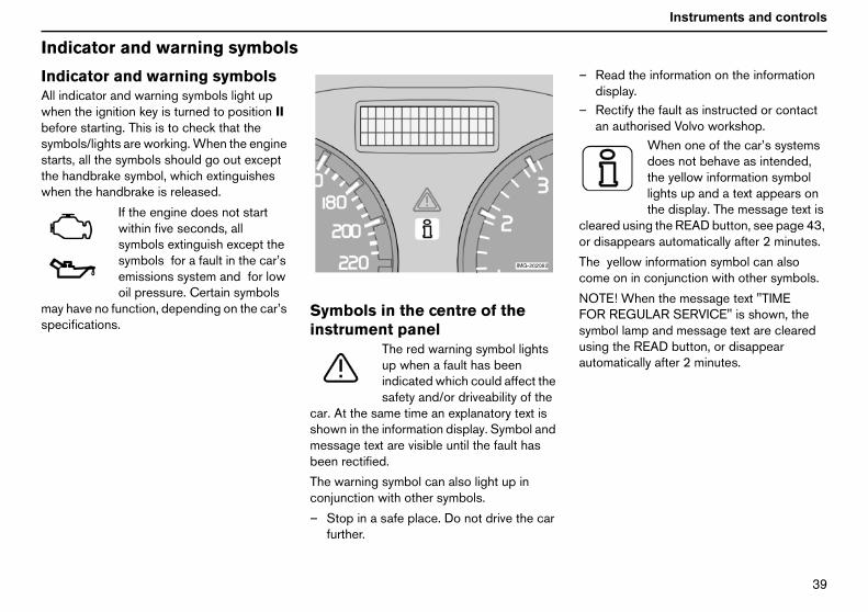
IndAllwhbefsymstathewh
maspe
Read the information on the informationdisplay.Rectify the fault as instructed or contactan authorised Volvo workshop.
When one of the car’s systemsdoes not behave as intended,the yellow information symbollights up and a text appears onthe display. The message text is
leared using the READ button, see page 43,r disappears automatically after 2 minutes.
he yellow information symbol can alsoome on in conjunction with other symbols.
OTE! When the message text "TIMEOR REGULAR SERVICE" is shown, theymbol lamp and message text are clearedsing the READ button, or disappearutomatically after 2 minutes.
icator and warning symbols
icator and warning symbolsindicator and warning symbols light upen the ignition key is turned to position IIore starting. This is to check that thebols/lights are working. When the engine
rts, all the symbols should go out excepthandbrake symbol, which extinguishes
en the handbrake is released.
If the engine does not startwithin five seconds, allsymbols extinguish except thesymbols for a fault in the car’semissions system and for lowoil pressure. Certain symbols
y have no function, depending on the car’scifications.
Symbols in the centre of theinstrument panel
The red warning symbol lightsup when a fault has beenindicated which could affect thesafety and/or driveability of the
car. At the same time an explanatory text isshown in the information display. Symbol andmessage text are visible until the fault hasbeen rectified.
The warning symbol can also light up inconjunction with other symbols.
– Stop in a safe place. Do not drive the carfurther.
–
–
co
Tc
NFsua

QM
Instruments and controls
Ind
IndsidFau
AB
–
–
dicator symbols — right-handidedicator symbol for trailer
This symbol flashes when thedirection indicators are used anda trailer is coupled. If the symboldoes not flash, one of the lamps
n the trailer or the car is defective.
arking brake appliedThis symbol is lit even if theparking brake is only applied onenotch. Check that the lever isproperly applied.
icator and warning symbols
icator symbols — left-handelt in car’s emissions system
Drive to an authorised Volvoworkshop to have the systemchecked.
S faultIf this symbol lights, the system isnot working. The car’s regularbrake system continues to work,but without the ABS function.
Stop the car in a safe place and turn offthe engine.Restart the engine.
– Drive to an authorised Volvo workshop tohave the ABS checked if the symbolremains lit.
Rear fog lampThis symbol is lit when the rearfog lamp is on.
STC or DSTC stability systemA flashing symbol indicates thatthe stability system is operating.
Engine preheater (diesel)This symbol is lit during enginepreheating. Preheating occurswhen the temperature is below-2 °C. The car can be started
once the symbol extinguishes.
Low level in fuel tankThis symbol lights when there areapproximately 8 litres of usablefuel left in a petrol-engined car, or7 litres in a diesel-engined car.
InsIn
o
P

QN
Instruments and controls
Air
syswo
Low
leveupaut
Se
Alt
Fau
WARNING!If the BRAKE and ABS symbols are lit atthe same time, there is a risk that the rearend will skid during heavy braking.
bags – SRSIf this symbol remains on orcomes on while driving, it meansa fault has been detected in theseatbelt buckle, SRS, SIPS, or IC
tem. Drive directly to an authorised Volvorkshop to have the system checked.
oil pressureIf this symbol lights up whiledriving, the engine oil pressure istoo low. Stop the engine immedi-ately and check the engine oil
l, top up if necessary. If the symbol lightsand the oil level is normal, contact anhorised Volvo workshop.
atbelt reminderThis symbol lights if someone in afront seat has not put on theirseatbelt or if someone in a rearseat has taken off their seatbelt.
ernator not chargingIf this symbol lights while driving,a fault has occurred in theelectrical system. Contact anauthorised Volvo workshop.
lt in brake systemIf this symbol lights, the brakefluid level may be too low.
– Stop the car in a safe place and check thelevel in the brake fluid reservoir, seepage 162. If the level in the reservoir isbelow MIN, the car should not be drivenany further. Transport the car to anauthorised Volvo workshop to have thebrake system checked.
If the BRAKE and ABS symbolscome on at the same time, theremay be a fault in the brake forcedistribution system.
–Stop the car in a safe placeand turn off the engine.
– Restart the engine.• If both symbols extinguish, continue
driving.• If the symbols remain on, check the level
in the brake fluid reservoir. See page 162.• If the brake fluid level is normal but the
symbols are still lit, the car can be driven,with great care, to an authorised Volvoworkshop to have the brake systemchecked.
• If the level in the reservoir is below MIN,the car should not be driven any further.Have the car transported to an authorisedVolvo workshop to have the brake systemchecked.

QO
Instruments and controls
Ind
ReIf ois nrem
Low
DOLEFBODOsaf
Hig
par
Bo
1
icator and warning symbols
minder — doors not closedne of the doors, the bonnet1 or the boot lidot properly closed, the driver will beinded of this.
speedIf the car is travelling at morethan 7 km/h, the informationsymbol will light and one of thefollowing texts will be shown onthe display: DRIVER
OR OPEN,PASSENGER DOOR OPEN,T REAR DOOR OPEN,NNET OPEN, or RIGHT REAROR OPEN. Stop the car as soon as it ise to do so and close the door that is open.
h speedIf the car is travelling at morethan 7 km/h, the warningsymbol will light and one of thetexts from the previous
agraph will appear on the display.
ot lid reminderIf the boot lid is open, this infor-mation symbol will come on andTAILGATE OPEN will appearon the display.
. Only cars with alarms.

QP
Instruments and controls
Inf
M
S mage.S mage.SSST , number of months since last service and
ormation display
MessagesWhen a warning or indicator symbol come, amessage appears on the information display.
– Press the READ button (A).Switch between messages with the READbutton. Fault messages are stored in thememory until the fault is rectified.
NOTE! If a warning message appears whileyou are using the trip computer, the messagemust be read (press READ) before theprevious activity can be resumed.
essage Specification
TOP SAFELY Stop and switch off the engine. Serious risk of daTOP ENGINE Stop and switch off the engine. Serious risk of daERVICE URGENT Leave the car for servicing immediately.EE MANUAL Read the owner’s manual.ERVICE REQUIRED Have your car serviced as soon as possible.IME FOR REGULAR SERVICE Time for service. The interval depends on distance
engine running time.

Instruments and controls
El
Eleequ
12TheaccandForkey
CigActThe
Ath
ectrical socket and switches on centre console
ctrical socket, DSTC system, extraipment
V electrical socketelectrical socket can be used for 12 V
essories, such as mobile phone chargerscoolers. The maximum current is 10 A.the socket to supply current, the ignitionmust be in at least position I.
arette lighter (option)ivate the lighter by pushing in the button.button pops out when the lighter is hot.
Pull out the lighter and light a cigarette on theheated coils.
Stability system, STC or DSTC1
The stability control system comes onautomatically when the car is started.
To suppress the stability control system:
– Press and hold the button for at least halfa second.
For further information, see page 113.
Extra equipmentSpace for an extra switch for retrofittedequipment.
WARNING!lways leave the plug in the socket whene socket is not in use.
1. Option on certain markets
WARNING!Suppressing the stability control systemalters the driving characteristics of the car.

QR
Instruments and controls
Lig
1.Thiheasothe•
•
Caraut
2.pa
Instrument lightingnual adjustment:Brighter illumination - move the controlupwards.Dimmer illumination - move the controldownwards.tomatic control:improve readability and save electricity, alight sensor automatically adjusts theghtness of the instrument lighting.
improve the clarity of the centre consoleplay, the background colour switchestween dark and light to suit lighting condi-s.
Front fog lamps (option)ition key in position II:ss the button. The front fog lamps lightng with the position/parking lamps andin/dipped beam. The LED in the button ishile the front fog lamps are on.
TE! In some countries, it is prohibited todipped beam or main beam at the same
e as front fog lamps.
Fuel filler flapss the button to open the fuel filler flap.
hting panel
Headlamp levellings control adjusts the height of thedlamp beam. This is used when the car isheavily laden that it affects the height ofbeams.
Normal bean height - move the controlupward (0).Lowered beam height - move the controldownward.s with Bi-Xenon headlamps (option) haveomatic headlamp levelling.
Headlamps and position/rking lamps
All lighting off.
Cars with daytime running lights(certain countries)Dipped beam comes on automatically whenthe ignition key is switched to the drivingposition (II) and cannot be switched off.Before trips to countries where automatic dipbeam is unsuitable, the daytime running lightscan be deactivated. Contact an authorisedVolvo workshop. Front and rear position/parking lamps, number plate lighting andinstrument lighting are lit at the same time asdipped beam.
Position/parking lampsFront and rear position/parkinglamps, number plate lighting andinstrument lighting. See alsopage 47.
Main and dipped beamIgnition key in position II:
Headlamps (plus front and rearposition/parking lamps, numberplate lighting and instrument
lighting) are lit.
NOTE! The light switch must be turned to thisposition to switch on the main beam.However, it is possible to flash the main beamin all positions, even when the ignition key isremoved. See also page 47.
3.Ma•
•
AuTotwibri
Todisbetion
4.IgnPrealomalit w
NOusetim
5.Pre

QS
Instruments and controls
Lig
6.IgnPrelamfronLEDcomfogswigoeaga
DaRemwhOnrea
NOrea
hting panel
Rear fog lampition key in position II:ss the button to switch on the rear fogp. The rear fog lamp lights along with thet fog lamps or main/dipped beam. Thein the button and the symbol in the
bined instrument panel light. If the frontlamps and the main or dipped beam aretched off and on again, the rear fog lamps out. Press the button to switch it onin.
zzlingember to switch off the rear fog lamp
en you see a car in the rearview mirror.ly the last car in a queue should have ther fog lamp switched on.
TE! Regulations for the use of front andr fog lamps vary from country to country.
QT
Instruments and controls
Le
DiranReWhtheTheres
NoThethemowhdire
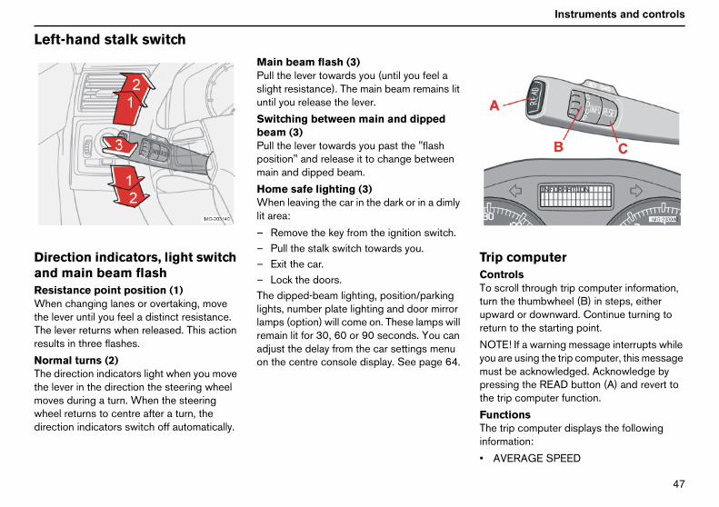
rip computerontrolso scroll through trip computer information,rn the thumbwheel (B) in steps, either
pward or downward. Continue turning toturn to the starting point.
OTE! If a warning message interrupts whileou are using the trip computer, this messageust be acknowledged. Acknowledge byressing the READ button (A) and revert toe trip computer function.
unctionshe trip computer displays the followingformation:
AVERAGE SPEED
ft-hand stalk switch
ection indicators, light switchd main beam flashsistance point position (1)en changing lanes or overtaking, movelever until you feel a distinct resistance.lever returns when released. This action
ults in three flashes.
rmal turns (2)direction indicators light when you movelever in the direction the steering wheel
ves during a turn. When the steeringeel returns to centre after a turn, thection indicators switch off automatically.
Main beam flash (3)Pull the lever towards you (until you feel aslight resistance). The main beam remains lituntil you release the lever.
Switching between main and dippedbeam (3)Pull the lever towards you past the "flashposition" and release it to change betweenmain and dipped beam.
Home safe lighting (3)When leaving the car in the dark or in a dimlylit area:
– Remove the key from the ignition switch.– Pull the stalk switch towards you.– Exit the car.– Lock the doors.The dipped-beam lighting, position/parkinglights, number plate lighting and door mirrorlamps (option) will come on. These lamps willremain lit for 30, 60 or 90 seconds. You canadjust the delay from the car settings menuon the centre console display. See page 64.
TCTtuure
Nympth
FTin
•

QU
Instruments and controls
Le
••••AveWhavebasdriv
SpCu
CuPresecupdcardis
AveTheresconswires
NOrea
1
ft-hand stalk switch
SPEED IN MILES PER HOUR1
CURRENT FUEL CONSUMPTIONAVERAGE FUEL CONSUMPTIONRANGE TO EMPTY FUEL TANKrage speeden the ignition is switched off, therage speed is stored and used as theis of the new value when you continueing. Reset using the RESET button (C).
eed in miles per hour1
rrent speed is displayed in mph.
rrent fuel consumptionsent fuel consumption is calculated everyond. The information on the display isated every couple of seconds. When theis stationary, " ---- " appears on the
play.
rage fuel consumptionaverage fuel consumption since the last
et (RESET). The average fuelsumption is stored when the ignition istched off and remains until the function iset. Reset using the RESET button (C).
TE! There may be a slight error in theding if a fuel-driven heater is used.
Range to empty fuel tankThis calculation is based on the average fuelconsumption over the last 30 km (19 miles)and the remaining fuel volume. It displays theapproximate distance that can be driven withthe fuel remaining in the tank. When therange to empty is less than 20 km (12 miles)"----" appears on the display.
NOTE! There may be a slight error in thereading if a fuel-driven heater is used.
Resetting– Select average speed or average fuel
consumption.– Press and hold the RESET button (C) for
at least five seconds to reset the averagespeed and average fuel consumption atthe same time.
. Certain countries

QV
Instruments and controls
Ri
WiA.B.C.D.Wi
he headlamps are washed the first time theindscreen is washed. Within the next teninutes, they are washed every fifth wash ofe windscreen. If more than ten minutesasses between washes, the headlamps areashed every time.
arking/position lamps selected with thewitch on the lighting panel:
Bi-Xenon headlamps are only washedevery fifth wash cycle irrespective of thetime that elapses.Halogen headlamps are not washed.
he switch on the lighting panel is inosition 0:
Bi-Xenon headlamps are only washedevery fifth wash cycle irrespective of thetime that elapses.Halogen headlamps are not washed.
ght-hand stalk switch
ndscreen wipersWindscreen and headlamp washersRain sensor - On/OffThumbwheelRear window wiper and washer
ndscreen wipers offThe windscreen wipers are offwhen the stalk switch is inposition 0.
Single sweepRaise the stalk switch to make asingle sweep.
Intermittent wipingThe delay between sweeps canbe adjusted. Turn thethumbwheel (C) upward for a
shorter interval between sweeps. Turn itdownward to increase the delay.
Continuous wipingThe wipers sweep at normalspeed.
The wipers sweep at highspeed.
Windscreen/headlamp washerPull the stalk switch towards the steeringwheel to start the windscreen and headlampwashers. The wipers will make three moresweeps once the stalk is released.
High-pressure headlamp washing(option on certain markets)
High-pressure headlamp washing consumesa large quantity of washer fluid. To save fluid,the headlamps are washed as follows.
Dipped beam selected with the switch onlighting panel:
Twmthpw
Ps
•
•Tp
•
•

RM
Instruments and controls
Ri
RaTheonwipspeadj
Tursen(Anthu
OnWhkeywin
ght-hand stalk switch
in sensor (option)rain sensor detects the amount of water
the windscreen so that the windscreeners automatically increase or decreaseed. The sensitivity of the rain sensor is
usted with the thumbwheel (C).
n the thumbwheel upward for highersitivity and downward for lower sensitivity.extra sweep is made when the
mbwheel is turned upward.)
/Offen activating the rain sensor, the ignitionmust be in at least position I and thedscreen wiper stalk must be in position 0.
To activate the rain sensor:
– press button (B). The rain sensor symbolis shown on the lower display.
To turn the rain sensor off, either:
– press button (B).– press the stalk switch downward to
another wiper program. If the stalk switchis raised, the rain sensor will remainactive; the wipers make an extra sweepand then return to rain sensor mode whenthe stalk is released to position 0.
The rain sensor is automatically deactivatedwhen the key is removed from the ignitionswitch or five minutes after the ignition isswitched off.
ThumbwheelUse the thumbwheel to adjust the frequencyof sweeps when intermittent wiping isselected, or the sensitivity to rain when therain sensor is selected.
Important!In an automatic car wash:Turn off the rain sensor by pressing button(B) while the ignition key is in at leastposition I. Otherwise, the windscreenwipers may start and be damaged.

RN
Instruments and controls
Cr
AcTheof t
Set
–
–
Crubel(12
emporary disengagementPress 0 to disengage the cruise controltemporarily. CRUISE will be shown on thecombined instrument panel. The speedset earlier is stored in the memory.
he cruise control is also temporarily disen-aged when:
the brake pedal or clutch pedal isdepressed.speed falls below 25-30 km/h whentravelling uphill1.the gear selector is moved to position N.wheel spin or wheel lock-up occurs.a temporary increase in speed lastslonger than one minute.
eturn to the set speedPress this button to resume thepreviously set speed.CRUISE ON appears on thecombined instrument panel.
isengagingress CRUISE to disengage the cruiseontrol. CRUISE ON goes out on theombined instrument panel.
uise control (option)
tivatingcontrols for cruise control are to the left
he steering wheel.
ting the desired speed:
Press the CRUISE button. CRUISE isshown on the combined instrument panel.Touch + or — to lock the vehicle speed.CRUISE ON appears on the combinedinstrument panel.ise control cannot be engaged at speeds
ow 30 km/h (20 mph) or above 200 km/h5 mph).
Increasing or decreasing speed– Increase or decrease the speed by
pressing and holding + or —. The speedof the car when the button is released isset as the new speed.
Pressing (less than half a second) + or —changes the speed 1 km/h (0.6 mph) or1.6 km/h (1 mph)1.
NOTE! A temporary increase in speed (lessthan one minute) using the accelerator, suchas while overtaking, does not affect the cruisecontrol setting. When you release the accel-erator, the car will return to the programmedspeed.
T–
Tg
•
•
•••
R
DPcc
1. Depending on engine type

RO
Instruments and controls
St
Thewhteleonkeystathe
Preforw
Theadj
Thethe
eering wheel keypad (option)
four buttons at the bottom of the steeringeel keypad control the radio and thephone. The function of a button depends
which system is active. The steering wheelpad can be used to scroll between presettions, change CD/MD tracks and adjustvolume.
ss and hold one of the arrow keys to fastard/reverse or search for the next station.
telephone must be in standby mode toust audio system settings.
telephone must be activated to controltelephone functions using the arrow keys.

RP
Instruments and controls
St
StThehei–
–
–
Adofchpo
eering wheel adjustment, hazard warning flashers
eering wheel adjustmentsteering wheel can be adjusted for both
ght and reach.Pull the lever towards you to release thesteering wheel.Adjust the steering wheel to the positionthat suits you best.Push back the lever to fix the steeringwheel in place. If the lever is stiff, pressthe steering wheel lightly at the same timeas you push the lever back.
Hazard warning flashersUse the hazard warning flashers (all directionindicators flash) when the car is stoppedwhere it could be a traffic hazard orobstruction. Press the button to activate thefunction.
NOTE! Regulations regarding the use ofhazard warning flashers vary from country tocountry.
WARNING!just the steering wheel before driving
f, never while driving. Before driving,eck that the steering wheel is fixed insition.

RQ
Instruments and controls
Pa
PaTheThewarpan
Thebrathe
To
–
EleTheacc
rking brake, electrical socket
rking brake (handbrake)lever is located between the front seats.parking brake acts on the rear wheels. A
ning symbol on the combined instrumentel lights when the brake is applied.
warning symbol lights even if the parkingke is only applied one notch. Check thatlever is properly applied.
release the parking brake:
Pull the lever up slightly and press in thebutton. Lower the lever and release thebutton.
ctrical socket in the rear seatelectrical socket can be used for 12 V
essories, such as mobile phone chargers
and coolers. The maximum current is 10 A.For the socket to supply current, the ignitionkey must be in at least position I.
Cigarette lighter (option)Activate the lighter by pushing in the button.The button pops out when the lighter is hot.Pull out the lighter and light a cigarette on theheated coils.
WARNING!Always leave the plug in the socket whenthe socket is not in use.

RR
Instruments and controls
Po
OpTheconmuwinto wkeydoo
To
–To
–RebutAllautcen
–
To
–
utomatic operationFully depress one of the controls (A) or(B) or raise it fully, then release. The sidewindow will then open or close automati-cally. If the window is obstructed by anobject, the movement will stop.
Mpath
WARNING!If there are children in the car:Remember to switch off the supply to thepower windows by removing the ignitionkey if the driver leaves the car.Make sure that children’s and otherpassengers’ hands are clear when closingthe windows.
WARNING!If the rear door windows are operatedfrom the driver’s door:Check that none of the rear seatpassengers are in danger of getting theirhands caught when closing the windows.
wer windows
erationpower windows are operated using the
trols in the door armrests. The ignition keyst be in position I or II for the powerdows to operate. The windows continueork when the car is stopped and ignitionremoved, provided neither of the frontrs is opened.
open a window:
Depress the front of the control.close a window:
Raise the front of the control.mote control and central lockingtonsside windows can be opened/closedomatically with the remote control or thetral locking buttons:
Press and hold the lock button for twoseconds - the windows will open or close.interrupt opening/closing:
Press the lock button again.
A. Front door window B. Rear door window
Driver’s doorThe driver can operate all of the powerwindows from the driver’s seat.
The windows in the front doors can beopened and closed in two ways:
Manual operation– Depress one of the controls (A) or (B)
gently or raise it gently. The powerwindow opens or closes as long as theswitch is actuated.
A–
WARNING!ake sure that children’s or otherssengers’ hands are clear when closinge windows by remote control.

RS
Instruments and controls
Po
BlochilBlodooThe
Thefrom
NOlocthatheeleme
ront passenger seat
ront passenger seathe control in the front passenger doorperates that window only.
1
wer windows
cking rear power windows and electricd safety locks1
cking power windows in the rearrsswitch LED is lit.
rear door windows can only be operatedthe driver’s door.
TE! If the car has electric child safetyks1 on the rear doors, the LED indicatest these are activated. The doors cannotn be opened from the inside. When thectric child safety locks are activated, a textssage is shown on the display.
The switch LED is unlitThe rear door windows can be operated bothwith the control on each rear door and withthe controls on the driver’s door.
F
FTo
. Option

RT
Instruments and controls
ReThethetheblothereathedoowin
ar power windowsrear door windows can be operated with
control on each door or with the switch ondriver’s door. If the LED in the switch for
cking the rear power windows (located incontrol panel in the driver’s door) is lit, ther door windows can only be operated fromdriver’s door. The windows in the rearrs are operated in the same way as thedows in the front doors.

RU
Instruments and controls
Re
IntDip1.2.3.
AuA sdettheVol
NOmirdim
alibrating the compasshe compass may need calibrating in specialases (setting points of the compass). Thetter C is shown in the mirror’s display if theompass needs calibrating.
Stop the car in a large open area.Start the car.Press and hold button (1) (use the pointof a pen or similar) for at least sixseconds. The character C will reappear.Drive slowly in a circle at a speed of nomore than 10 km/h until a compassdirection appears on the display.Calibration is complete.
arview and door mirrors
erior rearview mirrorpingDip the mirror with the leverNormal positionDipped position. Use this to reduceannoying dazzle from the headlights offollowing vehicles.
todimming (option)ensor (4) on the bottom edge of the mirrorects light coming from behind and dimsmirror if the light is strong. An authorisedvo workshop can adjust the sensitivity.
TE! The illustration is a montage. Theror has either manual dipping or automaticming, never both at the same time.
Rearview mirror with compass(option on certain markets)The upper right-hand corner of the rearviewmirror has an integrated display that showsthe compass direction in which the front ofthe car is pointing. Eight different directionsare shown with English abbreviations:N (north), NE (north east), E (east),SE (south east), S (south), SW (south west),W (west) and NW (north west).
CTclec
–––
–
–

RV
Instruments and controls
MaAdTheTheto w
Sel
––
–
oor mirrorshe controls for adjusting the two doorirrors are at the front of the driver’s door
rmrest.
Press the L button for the left-hand doormirror or R for the right-hand door mirror.The LED in the button lights.Adjust the position with the joystick in thecentre.Press the L or R button again. The LEDshould no longer be lit.
etractable power door mirrorsption)
he mirrors can be retracted for parking andriving in narrow spaces.
gnetic zonesjusting the zoneearth is divided into 15 magnetic zones.compass is set for the geographical areahich the car was delivered.
ect a different compass area as follows:
Turn on the ignition.Press and hold button (1) for at leastthree seconds (use the point of a pen orsimilar). The number for the current areais displayed.Press the button repeatedly until thenumber for the required geographicarea (1-15) is shown.
– The display will revert to showing thecompass direction a few seconds afteryou stop scrolling.
DTma
–
–
–
R(oTd

SM
Instruments and controls
Re
–
–
ImDthUpa
Thtoap
arview and door mirrors
Press the L and R button at the sametime.Release them after approximatelyone second. The mirrors automaticallystop in the fully retracted position.
Folding out the mirrors– Press the L and R button at the same
time. The mirrors automatically stop in thefully extended position.
Resetting to neutralMirrors that have been moved out of positionby an external force must be reset to theneutral position for electric retracting andextending to work.
Proceed as follows:
– Press the L and R button to retract themirrors.
– Extend the mirrors again with the L and Rbutton. The mirrors are now reset to theneutral.
Home safe and approach lightingThe lamps on the door mirrors light when thehome safe lighting or approach lighting isactivated.
portant!o not use a scraper to remove ice frome mirrors as this can scratch the glass.se the defroster function instead, seege 69.
WARNING!e driver-side door mirror is wide angledprovide optimal vision. Objects maypear further away than they actually are.

SN
Instruments and controls
Po
OpThepanpos
Venedg
Slid
The
Pull the control rearward to the endposition (1) and release.
liding positionutomatic operationull the control past the point ofsistance (2) to the rear end position (1) orast the point of resistance (3) to the forwardnd position (4) and release. The sunroofpens/closes completely.
anual operationpen:
Pull the control rearward to the point ofresistance (2). The sunroof moves towardthe fully open position as long as thebutton is held in this position.
lose:
Press the control forward to the point ofresistance (3). The sunroof moves towardthe closed position as long as the buttonis held in this position.
IfSbyle
WARNING!The sunroof’s pinch-protection functiononly operates during automatic closing,not manual closing.
wer sunroof (option)
en positionssunroof controls are located in the roofel. The sunroof can be opened to twoitions:
tilation position, raised at the reare (A).
ing position, backwards/forwards (B).
ignition key must be in position I or II.
1. Opening, automatic2. Opening, manual3. Closing, manual4. Closing, automatic5. Opening, ventilation position6. Closing, ventilation positionVentilation positionOpen:
– Press the rear edge of the control (5)upward.
Close:
– Pull the rear edge of the control (6)downward.
From ventilation position to fully opensunroof:
–
SAPrepeo
MO
–
C
–
WARNING!there are children in the car:witch off the supply to the power sunroof
removing the ignition key if the driveraves the car.

SO
Instruments and controls
Po
ClocoCloloc
–
If yo
–
wer sunroof (option)
sing using the remotentrol or central locking buttonsing using the remote control or centralking button:
Press and hold the lock button for twoseconds. The sunroof and windows closeand the doors lock.u need to interrupt closing:
Press the lock button again.
SunscreenThe sunroof features a manual, sliding interiorsunscreen. The sunscreen slides backautomatically when the sunroof is opened.Grip the handle and slide the screenforwards to close the screen.
Pinch protectionThe sunroof’s pinch protection function isactivated if the hatch is blocked by an object.If blocked, the sunroof will stop and automat-ically open to the previous position.
WARNING!Make sure that the hands of children andpassengers are clear when closing thesunroof by remote control.
WARNING!The sunroof’s pinch protection functiononly operates during automatic closing,not during manual closing.Make sure children’s hands are clearwhen closing the sunroof.

SP
Instruments and controls
Pe
Co
PoPerthe
ecirculation timerhen the timer is active, the air recirculatesr 3-12 minutes, depending on the outside
ir temperature.
Select On/Off depending on whether youwish the recirculation timer to be active.
eset allesets the climate function options to thectory settings.
ar settingsnlock feedback lighthe hazard warning flashers can provideedback when the car is unlocked with themote control. This function can be turnedn or Off.
ock feedback lighthe hazard warning flashers can provideedback when the car is locked with themote control. This function can be turnedn or Off.
utolockhe doors and boot lid can be lockedutomatically when the car starts to move.he setting options are On or Off.
nlock doorshere are two alternatives for unlocking:
All doors — one press of the remotecontrol unlocks all doors.
rsonal preferences
ntrol panel
ssible settingssonal preferences can be set for some ofcar’s functions: the locks, climate control
and audio functions. For audio functions, seepage 183.
Control panelA. DisplayB. MENUC. EXITD. ENTERE. NavigationUseThe settings are shown on the display (A).
Open the menu to enter settings:
– Press MENU (B).– Scroll, for example, to "Car Settings" with
the navigation button (E).– Press ENTER (D).– Select an alternative with the navigation
button (E).– Activate your selection with ENTER.Close the menu:
– Press EXIT (C) for approximately onesecond.
Climate controlAutomatic fan adjustmentThe fan speed can be set to AUTO mode incars equipped with ECC:
– Select between Low, Normal and High.
RWfoa
–
RRfa
CUTfereO
LTfereO
ATaT
UT
•

SQ
Instruments and controls
Pe
•
Ke•
•
•
•
ApSelonpreava
HoSelonbacThe30/
Inf•
rsonal preferences
Drivers door first, then all others — onepress of the remote control unlocks thedriver’s door. A second press thenunlocks all the other doors.
yless door openingAll doors - all doors are locked orunlocked at the same time.Doors on the same side - front and reardoors on the same side are unlockedtogether.Both front doors - both front doors areunlocked together.One front door - one of the front doors(either) can be unlocked separately.
proach lightingect the time the car’s lights should remainwhen the approach lighting button isssed. The following alternatives areilable: 30/60/90 seconds.
me safe lightingect the time the car’s lights should remainwhen the left-hand stalk switch is pulledk after the ignition key has been removed.following alternatives are available:
60/90 seconds.
ormationVIN (Vehicle Identification Number). Thecar’s unique identity number.
• Number of keys. The number of keysregistered for the car is shown.

SR
Climate controlGeneral information on climate control 66Manual climate control, A/C 68Electronic climate control, ECC (option) 70
Air distribution 73Fuel-driven parking heater (option) 74

SS
Climate control
Ge
AirTheandpaswithcon
NOoff,paswinon
MiRedonreg
IceRemconbon
FaAnmeor rEntper
ReTherefr
r vents in the dashboardOpenClosedLateral airflowVertical airflowthe outer vents towards the side
dows to remove misting.
ld weather: Close the centre vents fortimum comfort and best demisting.
neral information on climate control
conditioningclimate control system cools or heats,dehumidifies the air entering the
senger compartment. The car is equippedeither manual (A/C) or electronic climate
trol (ECC).
TE! The air conditioning can be switchedbut for optimum air quality in thesenger compartment and to prevent thedows from misting up, it should always be(even at temperatures of 0-15 °C).
sting windowsuce the problem of windows misting up
the inside by cleaning the windows. Use aular window cleaner.
and snowove ice and snow from the climate
trol air intake (the grille between thenet and the windscreen).
ult tracingauthorised Volvo workshop has the instru-nts and tools required for any fault tracingepair of your climate control system.rust checks and repairs only to trainedsonnel.
frigerantair conditioning system contains R134a
igerant. This refrigerant contains no
chlorine, which means that it is harmless tothe ozone layer. The system must only becharged with R134a refrigerant. Have anauthorised Volvo workshop carry out thiswork.
Passenger compartment filterAll air which enters the passengercompartment is first cleaned by a filter. Thisfilter must be replaced regularly. Follow theVolvo Service Programme for the recom-mended replacement intervals. If the car isused in a severely contaminated environment,it may be necessary to replace the filter moreoften.
NOTE! There are several different types ofpassenger compartment filter. Ensure thatthe correct filter is installed.
DisplayThere is a display above the climate controlpanel that displays climate control settings.
Personal preferencesYou can set preferences for two climatecontrol functions:
• Fan speed in AUTO mode (applies onlyto cars with ECC).
• Recirculation timer for passengercompartment air.
For information about these settings, seepage 63.
AiA.B.C.D.Aimwin
Coop

ST
Climate control
ECActThethefacrad
Se•
•
NOwith
SidTosatsun
AccThetemtem
VenDocarclo
C (option)ual temperaturetemperature you select corresponds tophysical experience with reference to
tors such as air speed, humidity and solariation in and around the car.
nsor location:The sun sensor is on the top side of thedashboard.The temperature sensor for thepassenger compartment is behind theclimate control panel.TE! Do not cover or block the sensorsclothing or other objects.
e windows and sunroofensure that the air conditioning worksisfactorily, close all side windows and theroof (if fitted).
elerationair conditioning system switches offporarily at full throttle. You may feel aporary rise in temperature.
tilation slots in the parcel shelfnot obstruct the ventilation slots for thego compartment in the parcel shelf withthing or other objects.
CondensationIn warm weather, condensation from the airconditioning system may drip under the car.This is normal.

SU
Climate control
Ma
Co1.2.3.4.5.6.7.8.9.
. RecirculationRecirculation can be used toshut out bad air, exhaustfumes, etc. from thepassenger compartment.The air in the passengercompartment is recirculated.
o outside air is taken into the car when thisnction is activated. Recirculation (togetherith the air conditioning system ) cools theassenger compartment more quickly in hoteather. If the air in the car recirculates foro long, there is a risk of the windowsisting.
nual climate control, A/C
ntrol panelFanRecirculationDefrosterAir distributionAC - ON/OFFHeated front left seatHeated front right seatRear window and door mirror defrostersTemperature
Functions1. Fan
Increase or decrease the fanspeed by turning the knob.
If the knob is turnedanticlockwise and the fanindicator in the display goesout, the fan and the air condi-
tioning are switched off. The display showsthe fan symbol and OFF.
2
Nfuwpwtom

SV
Climate control
TimThemisSeepagthegag
3. D
•
•
•4. A
abo
nction is active if one LED is lit in the switch.he door mirror heating is deactivatedutomatically after approximately 6 minutes.he rear window heating is deactivated afterpproximately 12 minutes.
. TemperatureSelect cooling or heating forboth driver and passengerside.
ertimer function minimises the risk of icing,
ting and bad air if recirculation is selected.the Personal Preferences section,
e 63, for how to activate and deactivatefunction. Recirculation is always disen-ed when you select Defroster (3).
efrosterDefroster quickly removesmisting and ice from thewindscreen and sidewindows.
Air is directed to the windows at high fanspeed.The LED in the defroster button lightswhen the function is active. The air condi-tioning system gives maximum dehumidifi-cation.The air does not recirculate.ir distribution
The airflow can bedistributed to the windows,dashboard vents or floor bypressing the air distributionbuttons.
A symbol on the displayve the climate control panel and a lit LED
in the button indicate which function hasbeen selected.
See the table on page 73.
5. AC - ON/OFFON: Air conditioning isengaged.OFF: Air conditioning isdisengaged. If Defroster (3)is activated the air condi-tioning is always engaged.
6 and 7. Heated front seats(option on certain markets)
–Higher heat levelPress the button once -both LEDs light.–Lower heat level
Press the button twice - one LED lights.– Heat off
Press the button three times - LEDs notlit.
8. Rear window and door mirrordefrosters
Heating is used to quicklyremove misting and ice fromthe rear window and doormirrors.
The rear window and doormirrors are defrosted simul-
taneously if the switch is pressed once. The
fuTaTa
9

TM
Climate control
El
Co1.2.3.4.5.6.7.8.9.10.
. FanIncrease or decrease fanspeed by turning the knob.The fan speed is regulatedautomatically if AUTO isselected and the previouslyset fan speed is disengaged.
OTE! If the knob is turned anticlockwise ande fan indication on the display goes out, then and the air conditioning are switched off.he display shows the fan symbol and OFF.
ectronic climate control, ECC (option)
ntrol panelAUTOFanRecirculation/Air quality systemDefrosterAir distributionAC - ON/OFFHeated front left seatHeated front right seatRear window and door mirror defrostersTemperature
Functions1. AUTO
The AUTO functionautomatically regulatesclimate control andmaintains the desiredtemperature. The AUTOfunction controls heating, air
conditioning, fan speed, recirculation, and airdistribution. If you select one or more manualfunctions, the other functions continue to becontrolled automatically. All manual settingsare switched off when AUTO is switched on.The display shows AUTO CLIMATE.
2
NthfaT

TN
Climate control
3. R
Nofunculon
TimThemisSeeto a
NOcula
3. A
parpolWhair,pas
. DefrosterDefroster quickly removesmisting and ice from thewindscreen and sidewindows. Air flows to thewindows at high fan speed.The LED in the defroster
utton lights when the function is active. Their conditioning system gives maximumehumidification. The air is not recirculated.
. Air distributionThe airflow can bedistributed to the windows,dashboard vents or floor bypressing the air distributionbuttons.
A symbol on the displaybove the climate control panel and a lit LEDthe button indicate which function has
een selected.
ee the table on page 73.
. AC— ON/OFFThe air conditioning systemis controlled automaticallyby the system when the ONLED is lit. This way,incoming air is sufficientlycooled and dehumidified.
hen the OFF LED lights, the air condi-oning system is always disengaged. Other
ecirculationRecirculation can be used toshut out bad air, exhaustfumes, etc. from thepassenger compartment.The air in the passengercompartment is recirculated.
outside air is taken into the car when thisction is activated. If the air in the car recir-ates for too long, there is a risk of mistingthe insides of the windows.
ertimer function minimises the risk of icing,
ting and bad air if recirculation is selected.Personal Preferences, page 63, for how
ctivate and deactivate the function.
TE! When Defroster (4) is selected, recir-tion is always deactivated.
ir quality system (option)(same button as recircu-lation)
The air quality systemconsists of a multi-filter anda sensor. The filterseparates gases and
ticles to reduce the levels of odours andlution in the passenger compartment.en the sensor detects polluted outsidethe air intakes are closed and the air in thesenger compartment is recirculated.
A green LED (A) lights in the button when theair quality sensor is active.
Activating the air quality sensor:• Press the AUTO button (1) to activate the
air quality sensor (normal setting).Or:
Switch between three functions by pressingrepeatedly the recirculation button.
• Air quality sensor engaged - LED (A)lights.
• No recirculation engaged, provided it isnot required for cooling in hot weather -LED not lit.
• Recirculation engaged - LED (M) lights.Keep in mind the following:• As a rule, the air quality sensor should
always be engaged.• Recirculation is limited in cold weather to
avoid misting.• If the insides of the windows start misting
up, disengage the air quality sensor.• The defroster function for the front, side
and rear windows can also be used todemist the windows.
4
bad
5
ainb
S
6
Wti

TO
Climate control
El
funWhtioncat
7 a
–
–
–
9. H
tanfunTheautTheapp
ectronic climate control, ECC (option)
ctions are still controlled automa tically.en Defroster (4) is selected, the air condi-ing system is set for maximum dehumidifi-ion.
nd 8. Heated front seats(option on certain markets)
To activate front seatheating:
Higher heat level:Press the button once - both LEDs light.Lower heat level:Press the button twice - one LED lights.Heat off:Press the button three times - LEDs not lit.
eated rear window and door mirrorsHeating is used to quicklyremove misting and ice fromthe rear window and doormirrors.
The rear window and doormirrors are defrosted simul-
eously if the switch is pressed once. Thection is active if one LED is lit in the switch.door mirror heating is deactivated
omatically after approximately 6 minutes.rear window heating is deactivated afterroximately 12 minutes.
10. Temperature selectorThe temperatures on thedriver and passenger sidescan be set independently.
Press the button once toactivate one side. Pressagain to activate the other
side. Press the button a third time to activateboth sides.
The active side is indicated by an LED in thebutton and on the display above the climatecontrol panel.
When the car is started, the previous settingsare resumed.
NOTE! Heating or cooling cannot behastened by selecting a higher or lowertemperature than the actual desiredtemperature.

TP
Climate control
Ai
Airistribution Use:the floor andws. Some airto the dashboardnts.
To ensurecomfortable condi-tions and gooddemisting in cold orhumid weather.
floor and fromoard air vents.
In sunny weatherwith cool outsidetemperatures.
the floor. Somews to theoard air ventsindows.
To warm the feet.
w to windows,dashboard airand to the floor.
To provide cooler airfor the feet orwarmer air to theupper body in coldweather or hot, dryweather.
r distribution
distributionAir distribution Use: Air dAir to windows. Someair flows to thedashboard air vents.The air is not recircu-lated. Air conditioning isalways engaged.
To remove ice andmisting quickly.
Air towindoflowsair ve
Air to windscreen andside windows. Some airflows to the dashboardair vents.
To prevent mistingand icing in a coldand humid climate.(Not for low fanspeed.)
Air todashb
Airflow to windows andfrom dashboard airvents.
To ensure goodcomfort in warm, dryweather.
Air toair flodashband w
Airflow to the head andchest from thedashboard air vents.
To ensure efficientcooling in warmweather.
Airflofromvents

TQ
Climate control
Fu
GeheTheateusinrefeTheheaoutthetem
arning decal on fuel filler flap
WARNING!The car must be outdoors when the petrolor diesel heater is used.
el-driven parking heater (option)
neral information aboutatersparking heater can be started immedi-
ly or set with two different start timesg TIMER 1 and TIMER 2. Here, start timers to the time the car is heated and ready.car’s electronic system calculates when
ting should be started based on theside temperature. The heater is not run ifoutdoor temperature exceeds 25 °C. Atperatures of −10 °C and below, the
maximum running time of the parking heateris 60 minutes.
W
WARNING!The car must be outdoors when the petrolor diesel heater is used.
WARNING!Switch off the fuel-driven heater beforerefuelling. Spilled fuel could be ignited bythe exhaust gases.Check on the information display that theheater is off. (When the additional heateris running, PARK HEAT ON is shown onthe information display.)

TR
Climate control
Ac–
–
PaIf ththethe
Dir–
–
–
Im–
–
–NOwh
Scroll with the thumbwheel to the desiredminute.Touch RESET to confirm the setting.Press RESET to activate the timer. Aftersetting TIMER 1, a second start time canbe programmed with TIMER 2 . Accessthis with the thumbwheel. Set the alter-native start time in the same way asTIMER 1.
tivating the heaterEnter the time when the car is to be used.Press RESET (C) to enter the hours andminutes.Press and hold the RESET button untilthe timer is activated.
rking on a hille car is parked on a steep hill, the front ofcar should point downhill to ensure thatre is a supply of fuel to the parking heater.
ect startUse the thumbwheel (B) to scroll toDIRECT START.Press RESET (C) to access the optionsON and OFF.Select ON. The heater will now run for60 minutes. Heating of the passengercompartment will begin as soon as theengine coolant has reached a temper-ature of 30 ºC.
mediate stop of heaterUse the thumbwheel (B) to scroll toDIRECT START.Press RESET (C) to access the optionsON and OFF.Select OFF.TE! The car can be started and drivenile the parking heater is still running.
Battery and fuelIf the battery has insufficient charge or thefuel level is too low, the parking heater will beswitched off automatically. A messageappears on the information display.Acknowledge the message by pressing theREAD button (A).
Setting TIMER 1 and 2For safety reasons, you can only programmetimes for the following 24 hours, not severaldays in advance.
– Scroll with the thumbwheel to TIMER.– Touch RESET to move to the flashing
hours setting.– Scroll with the thumbwheel to the desired
hour.– Touch RESET to move to the flashing
minutes setting.
–
––
Important!Repeated use of the parking heatercombined with short journeys maydischarge the battery and impair starting.If the heater is used regularly, the carmust be driven for the same as the heateris run to ensure that the alternator hastime to charge the battery.

TS
Climate control
Fu
MeWhSTAonanmawhthe
CloIf tharecan
Ad(ce
Extreqtem
Thewhrunthethe
el-driven heater (option)
ssages on the displayen TIMER 1, TIMER 2 and DIRECTRT are activated, the information symbol
the combined instrument panel lights andexplanatory text appears on the infor-tion display. The display also indicatesich timer is active when the driver removeskey from the ignition to leave the car.
ck/timere car clock is reset after the heater timersprogrammed, the selected times will becelled.
ditional heater (diesel)rtain countries)
ra heat from the additional heater may beuired in cold weather to reach the correctperature in the passenger compartment.
additional heater starts automaticallyen extra heat is required if the engine isning. It is switched off automatically whencorrect temperature is reached or whenengine is switched off.

TT
InteriorFront seats 78Interior lighting 80Storage spaces in the passenger compartment 82
Rear seat 84Cargo area 86

TU
Interior
Fr
SeTheadjpos
1.
2.
3.
4.
owering the front seatackresthe passenger seat backrest can be foldedrward to make room for long loads.
Move the seat as far back as possible.Adjust the backrest to an upright position90 degrees.Lift the catches on the rear of thebackrest while folding it forwards.
ont seats
ating positiondriver’s and passenger seats can be
usted to the optimum sitting and drivingitions.
Forward/backward: lift the handle toadjust the distance to the steeringwheel and pedals. Check that the seat islocked after changing position.Raise/lower the front of the seatcushion: pump up/down (option onpassenger side).Raise/lower the seat: pump up/down(option on passenger side).Lumbar support (option, passengerside), turn the wheel.
5. Backrest rake: turn the wheel.6. Control panel for power seat (option).Controls (2) and (3) are not present on allseat models.
LbTfo
––
–
WARNING!Adjust the position of the driver’s seatbefore setting off, never while driving.Check that the seat is locked in position.

TV
Interior
PoPreThekeywithwithcloigncanbei
MeThestoto tunl
bout 20 seconds before adjusting the seatgain.
mergency stopthe seat accidentally begins to move, pressne of the buttons to stop the seat.
WARNING!Ensure that there is nothing in front of,behind, or under the seat duringadjustment.Ensure that none of the backseatpassengers will be trapped.To avoid injury, ensure that children do notplay with the switches.
wer seat (option)parationsseat is normally adjusted with the ignitionis in position I or II. It can also be adjustedin 10 minutes of the door being unlockedthe key or remote control. If the door is
sed and the ignition key is not yet in theition, or is in the 0 position, adjustmentsbe made within 40 seconds of the door
ng closed.
mory function in remote controlremote control used to unlock the car
res information about the changes madehe seat settings. When the car is nextocked with the same remote control and
the door is opened within two minutes, thedriver’s seat returns to the stored position.
Seat with memory function (option)1. Seat adjustment, memory 12. Seat adjustment, memory 23. Seat adjustment, memory 34. Storing preset positionsThree positions can be stored. Afteradjusting the seat, press and holdbutton M (4) and then press button (1).Further seat settings can be stored in thememory using memory buttons (2) and (3).
Setting preset positionsPress and hold one of the memorybuttons (1), (2) or (3) until the seat stops. Ifyou release the button, the seat stopsimmediately for safety reasons.
Seat adjustmentThe following can be set with switches (5),(6) and (7):
5. Backrest rake6. Seat forward/backward and up/down7. Front edge of seat cushion up/downOnly one of the electric motors can beoperated at a time. The power front seatshave overload protection which is tripped if aseat is blocked by an object. If this happens,turn off the ignition (position 0) and wait
aa
EIfo

UM
Interior
Int
Fro1.2.3.Thecomthe
Swpas
•
•
ar seat lightingrn the lights on or off by pressing thepropriate button. The lighting is turned offomatically ten minutes after the engine isitched off.
erior lighting
nt seat lightingLighting for left-hand sideSwitchLighting for right-hand sidelighting in the front part of the passengerpartment is controlled with the buttons inroof console.
itch (2) has three positions for allsenger compartment lighting:
Off - right side depressed, passengercompartment lighting is switched off.Neutral position - passengercompartment lighting comes on when adoor is opened and goes out when thedoor is closed. The dimmer function isactive.
• On - left side depressed, passengercompartment lighting is on.
Automatic lightingThe interior lighting switches on and offautomatically when switch (2) is in the neutralposition. See illustration.
The lighting comes on and remains on for30 seconds if:
• the car is unlocked from outside with thekey or remote control.
• the engine is stopped and the ignition keyis turned to position 0.
The compartment lighting comes on andremains on for five minutes if:
• one of the doors is open.• the lighting is not switched off.The interior lighting is switched off when:
• the engine is started.• the car is locked from outside with the key
or remote control.The interior lighting is automatically switchedoff five minutes after the engine is switchedoff. The interior lighting can be switched on oroff within 30 minutes of the key being turnedto position 0 by briefly pressing button 2. Theprogrammed times can be changed inaccordance with the instructions in thePersonal Preferences section, see page 59.
ReTuapautsw

UN
Interior
VaThecov
1
nity mirror1
light comes on automatically when theer is lifted.
. Option on certain markets.

UO
Interior
St
orage spaces in the passenger compartment
UP
Interior
St1.
2.3.4.5.6.7.
ImThaha
EobthbrAw
orage spacesStorage pocket (also on the front edgeof the front seat cushions).Compartment in door panel.Ticket clip.Glovebox.Waste bin (accessory).Storage compartment and cup holder.Storage compartment and cup holder.
GloveboxThe owner’s manual and maps can be kepthere. There are also holders for coins, pensand fuel cards. The glovebox can be lockedwith the removable key blade in the remotecontrol. For further information about the key,see page 88.
Floor mats (option)Volvo supplies floor mats specially manufac-tured for your car. These should be properlyanchored with the clips on the floor so theydo not slide and get jammed beside or underthe driver’s pedals.
portant!e waste bin (5) must not be mounted ifphone handset is mounted on the right-nd side of the centre console.
WARNING!nsure that no hard, sharp or heavyjects lie or protrude in such a way that
ey could cause injury during heavyaking.lways secure large and heavy objectsith a seatbelt or cargo retaining straps.

UQ
Interior
Re
CeAllto sedgwiththeheahanthe
Tobuthea
ipping the rear seat backresthe rear seat backrests can be tippedrwards together, or individually, to make it
asier to transport long objects. To avoidamaging the seatbelts when folding theackrests up or down, these should beooked onto the grab handles.
Hang the seatbelts on the hooks beforelowering or raising the backrests.Lift the rear edge of the seat cushion (1)in order to fold the seat cushions forward.
ar seat
ntre rear head restrainthead restraints can be adjusted verticallyuit the height of the passenger. The uppere of the head restraint should be alignedthe middle of the back of the head. Raise
head restraint if necessary. To lower thed restraint, press the button by the right-d pillar at the same time as pushing downhead restraint.
remove the head restraint, press theton by the right-hand pillar while lifting thed restraint.
TTfoedbh
–
–
Important!The head restraints can be damaged ifthey are not removed for loading. Thecentre head restraint must also beremoved for heavy loads.

UR
Interior
Low–
–
–
NOtheshopla
ering the backrestPull the lock (2) catch up and forward torelease the backrest. A red indicator onthe lock catch shows that the backrest isno longer locked in place.Fold the backrest (3) forward halfway andremove the head restraint. The centreseat’s head restraint must be loweredfully or removed.Place the head restraints in the plasticsleeves on the undersides (4) of theraised seat cushions.TE! When the backrest has been raised,red indicator should no longer bewing. If it is, the backrest is not locked ince.
WARNING!Remember to take down the seatbeltsonce you have raised the backrest.

US
Interior
Ca
LoThestraare
ag holder (option)he bag holder holds shopping bags in placend prevents them tipping over and spillingeir contents.
Open the hatch in the cargo area.Secure the shopping bags with the strap.
rgo area
ad retaining eyeletsload retaining eyelets are used to fastenps or nets to anchor items in the cargoa.
Electrical socket in the cargoareaFold down the cover to access the electricalsocket. This socket works regardless ofwhether the ignition is on. If the ignition isswitched off and an appliance requiring acurrent greater than 0.1 A is plugged into theelectrical socket, a warning messageappears on the information display. Avoidusing the electrical socket with the ignitionswitched off due to the risk of running thebattery flat.
BTath
––

UT
Locks and alarmRemote control with key blade 88Keyless drive (option) 91Locking and unlocking 93
Child safety locks 95Alarm (option) 96

UU
Locks and alarm
Re
ReTheTheconfordrivlabKeeautnewkeyone
LoIf yotheVolrempre
ImThechireacarcon
. Boot lid - Press the button once tounlock the boot lid only.
. Panic function - Used to attract attentionin an emergency. Press and hold the redbutton for at least three seconds orpress it twice within three seconds toactivate the direction indicators and thehorn. The function can be turned off withthe same button once it has been activefor at least five seconds. The functionswitches off automatically after30 seconds.
ey bladehis feature is intended for when leaving thear, such as for servicing or valet parking at aotel. Hand over the remote control and keepe removable key blade.
ccess to the glovebox and cargoompartment can be prevented using the
mote control's removable key blade1. Thiseans that the remote control can only opene doors and that the car can be driven.
Important!The narrow section of the remote controlis particularly sensitive - this contains thechip. The car cannot be started if the chipis damaged.
1. Certain markets only
mote control with key blade
mote controlcar is supplied with two remote controls.se also work as ignition keys. The remotetrols contain a removable metal key bladethe manual locking and unlocking of theer’s door and the glovebox. A separateel with the code for key blade is included.p this label in a safe place. Take it to an
horised Volvo workshop when orderingkeys. A maximum of six remote controls/
blades can be programmed and used forcar.
ss of a remote controlu lose a remote control, take the car andother remote control to an authorisedvo workshop. The code of the missingote control must be erased as a theftvention measure.
mobiliserremote controls are fitted with coded
ps. The code must be accepted by theder (receiver) in the ignition switch. Thecan only be started if the correct remotetrol with the correct code is used.
Remote control functions1. Locking - Locks the doors and the boot
lid. Press and hold to close the windowsand sunroof.
2. Unlocking - Unlocks the doors and bootlid. Press and hold to open thewindows.
3. Approach lighting - When you approachthe car:Press the yellow button on the remotecontrol to switch on the interior lighting,position/parking lights, number platelighting and door mirror lamps (option).The lighting is switched off automaticallyafter 30, 60 or 90 seconds. For how toset the desired delay time, see page 64.
4
5
KTchth
Ac
remth
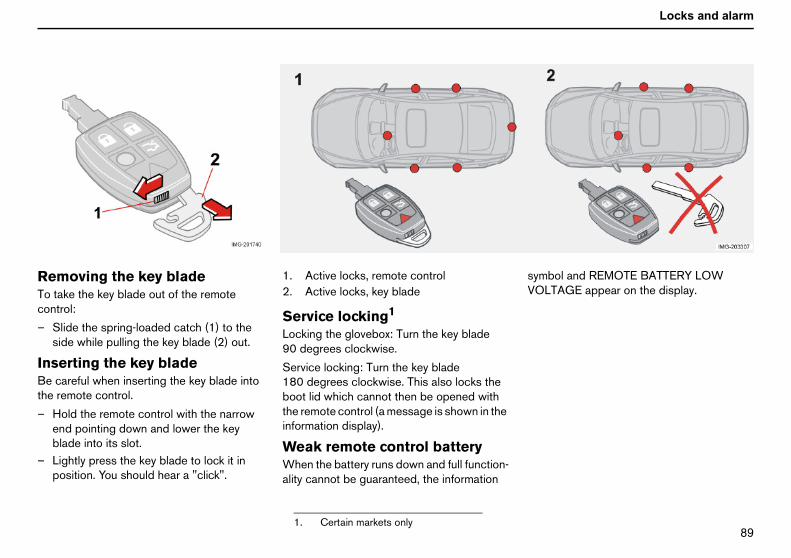
UV
Locks and alarm
ReTocon
–
InsBethe
–
–
bol and REMOTE BATTERY LOWLTAGE appear on the display.
moving the key bladetake the key blade out of the remotetrol:
Slide the spring-loaded catch (1) to theside while pulling the key blade (2) out.
erting the key bladecareful when inserting the key blade intoremote control.
Hold the remote control with the narrowend pointing down and lower the keyblade into its slot.Lightly press the key blade to lock it inposition. You should hear a "click".
1. Active locks, remote control2. Active locks, key blade
Service locking1
Locking the glovebox: Turn the key blade90 degrees clockwise.
Service locking: Turn the key blade180 degrees clockwise. This also locks theboot lid which cannot then be opened withthe remote control (a message is shown in theinformation display).
Weak remote control batteryWhen the battery runs down and full function-ality cannot be guaranteed, the information
symVO
1. Certain markets only

VM
Locks and alarm
Re
ChbaIf thsigdis(typ
––
––
mote control with key blade
anging the remote controltterye locks repeatedly fail to respond to
nals from the remote control at a normaltance, the battery should be changede CR 2032, 3 volt).
Pull out the key blade.Place the remote control with the keypaddownward and remove the screw (1)using a small screwdriver.Remove the cover.Carefully note the position of the battery’s+ and – poles on the inside of the cover.
– Prise out (2) and change the battery.Avoid touching the battery and itsterminals with your fingers.
– Refit the cover and screw it shut.– Press the key blade back into place.Dispose of the old battery in an environmen-tally-friendly way.

VN
Locks and alarm
Ke
KesysTheunlforcon
Theconshoothfor
Thekeyaddsys
he warning message and reminder signalisappear when the remote control isrought back to the car after one of thellowing actions:
a door has been opened and closedthe ignition dial has been turned toposition Ithe READ button has been pressed.
o not leave a remote control in the cara keyless drive remote control is left in thear, it becomes passive when you lock thear. No unauthorised person can open theoor. But if someone breaks into the car andnds the remote control, it can be activatednd used again.
yless drive (option)
yless lock and ignitiontemkeyless drive system allows the car to be
ocked, driven and locked without the needa key. You simply have to have the remotetrol with you in a pocket or bag.
system makes it easier and morevenient to open the car, for example withpping bags in one hand and a child in theer. It saves you having to take out or lookthe remote control.
two remote controls incorporate theless drive feature. You can orderitional remote controls. The keyless drivetem can handle up to six remote controls.
Remote control max. 1.5 m from the carTo be able to open a door or the boot lid, theremote control must be within a maximum ofapproximately 1.5 m of the car’s doorhandles or boot lid. The grey shaded area inthe image shows the area covered by thesystem’s antennae.
If someone leaves the car and takes withthem a keyless drive remote control, awarning message appears on the informationdisplay while a reminder signal is heard. Thewarning message disappears when theremote control is brought back to the car orthe ignition dial is turned to position I. Thewarning is only issued if the key dial is inposition 1 or 2 after someone has openedand closed a door.
Tdbfo
••
•DIfccdfia

VO
Locks and alarm
Ke
IntEleinteavo
Dophome
If inusenor
ll doors and the boot lid must be closedefore the lock button is pushed in.therwise they will not lock.
hen the car is locked, the lock buttons one inside of the doors retract in the normalay.
ersonal settings for keylessrivehe keyless drive system can be tailored toour personal requirements. Read morebout personal settings on page 64.
yless drive (option)
erference to remote control functionctromagnetic screening and fields canrfere with the keyless drive system. Toid this:
not place the remote control near mobilenes, metallic objects or, for example, in a
tal briefcase.
terference is experienced nonetheless,the remote control and key blade in the
mal way. See page 88.
UnlockingUnlock the car by:
– opening one of the doors with the handleor opening the boot lid by pressing thebutton.
Power seat (option) — remote controlwith memory functionIf several people with keyless drive remotecontrols get into the car, the driver’s seat willbe adjusted for the person who opens thedoor first.
LockingLock the doors and boot lid by:
– pushing in the lock button on one of thedoor handles.
AbO
Wthw
PdTya

VP
Locks and alarm
Lo
LoouYouandremunl
AuIf nowithlocpreunipag
UnTo
–
If aclountor f
e locked manually with their respective lockuttons. Pull the door handle twice to unlocknd open the door from the inside.
Bif
cking and unlocking
cking/unlocking the car fromtsidecan lock and unlock all the car’s doorsthe boot lid simultaneously using theote control. The driver’s door can be
ocked with the key blade.
tomatic relockingne of the doors or the boot lid are openedin two minutes of unlocking, all are
ked again automatically. This functionvents the car from being left unlockedntentionally. For cars with alarms, seee 97.
locking the boot lidunlock only the boot lid:
Press the boot lid button on the remotecontrol.ll doors are locked when the boot lid issed, then the boot lid remains unlockedil the car is locked with the remote controlrom inside.
Locking/unlocking the car frominsideAll the doors and the boot lid can be lockedor unlocked simultaneously using the switchby the door handle.
Unlocking– Press the upper section of the lock
button. Press and hold to also open theside windows.
Locking– Press the lower part of the lock button.
Press and hold to also close the windowsand sunroof.
It is not possible to unlock a door by pullingup the lock button. All the doors can however
bba
WARNING!e aware that you can be locked in the carit is locked from the outside.

VQ
Locks and alarm
Lo
LoTheunlrem
–
–
emporary deactivation of theeadlocks and any detectorssomeone is going to stay in the car but youtill want to lock the doors from the outside,e deadlocks can be disabled.
Insert the key into the ignition switch, turnit to position II and then back to position Ior 0.Press button 1.
the car is equipped with an alarm,ovement and tilt detectors are also deacti-
ated. See page 97.
he LED in the button lights up until the car iscked with the key or the remote control. Aessage remains on the display as long ase key is in the ignition switch. The detectors
re reactivated the next time the ignition iswitched on.
WARNING!Do not allow anyone to remain in the carwithout first deactivating the deadlocks.
cking and unlocking
cking the gloveboxglovebox can only be locked and
ocked with the removable key blade in theote control.
Unlock the glovebox (1) by turning the keya quarter of a turn (90 degrees)anticlockwise. The keyhole is vertical inthe unlocked position.Lock (2) the glovebox by turning the key aquarter of a turn (90 degress) clockwise.The keyhole is horizontal in the lockedposition.
1. Deactivation of the detectors2. No function
DeadlocksWhen deadlocked, the doors cannot beopened from the inside if they are locked. Thedeadlocks are activated with the remotecontrol. The deadlocks are set after a25 second delay after the doors are locked.
The car can only be unlocked from adeadlock state with the remote control. Thedoors can also be opened from the outsidewith the key.
TdIfsth
–
–Ifmv
Tlomthas

VR
Locks and alarm
Ch
Ma
MadoTofouandopethuloc
A.
B.
lectric child safety locks andisabling the rear windowuttons (option)ress the switch on the driver’s door. Aessage appears on the information display.
hen the electric child safety locks arectivated, the rear window buttons areisabled.
o activate the child safety locks:
Turn the ignition key to position I or II.Press the switch. When the LED in theswitch is lit, the rear window buttons aredisabled.
message appears on the informationisplay when the child safety locks arectivated.
OTE! Cars with electric child safety lockso not also have manual child locks.
hild safety locks activatedlit LED together with a text message on the
isplay indicates that the locks are activated.he doors cannot be opened from inside. Theower windows can only be operated withe controls on the driver’s door.
ild safety locks
nual child lock in rear left door.
nual child locks in the rearorslock manually: The child safety locks arend on the trailing edge of the rear doorsare only accessible when the doors aren. Use the key blade to turn the lock and
s activate or deactivate the child safetyk.
The doors cannot be opened frominside.The doors can be opened from inside.
Switch for electric child safety locks anddisengaging rear power window buttons.
EdbPm
Wad
T
––
Ada
Nd
CAdTpth
WARNING!Always keep the lock buttons pulled upwhen driving. In the event of an accident,this allows the emergency services to getinto the car quickly. Passengers in the rearseat cannot open the doors from inside ifthe child safety locks are activated.

VS
Locks and alarm
Al
ThWhmo
The
•
•
•
•
••
OTE! Do not attempt to repair or modifylarm system components. All such attemptsay affect the terms of insurance.
rming the alarmPress the LOCK button on the remotecontrol. A long flash from the car’sdirection indicators confirms that thealarm is armed and that all the doors arelocked.
isarming the alarmPress the UNLOCK button on the remotecontrol. Two short flashes from the car’sdirection indicators confirms that thealarm is disarmed and all doors areunlocked.
arm (option)
e alarm systemen the alarm is armed, it continuallynitors all alarm inputs.
alarm is triggered if:
a door, the bonnet or the boot lid isopened.a non-approved key is used in the ignitionor if an attempt is made to force the lock.a movement is detected in the passengercompartment (if fitted with a movementdetector).the car is raised or towed away (if fittedwith a tilt detector).a battery cable is disconnected.anyone tries to disconnect the siren.
Alarm LED on the dashboardAn LED on the dashboard indicates the alarmsystem’s status:
• LED not lit - the alarm is not armed.• The LED flashes once a second - the
alarm is armed.• The LED flashes rapidly after disarming
the alarm and until the ignition is switchedon - the alarm has been triggered.
If there is a fault in the alarm system, amessage appears on the information display.Contact an authorised Volvo workshop.
If the alarm system does not work correctly,let an authorised Volvo workshop examinethe car.
Nam
A–
D–

VT
Locks and alarm
AuThileav
If nopealartherea
Sw–
Cofrom
. Deactivation of the detectors
. No function
emporary deactivation of theeadlocks and detectorso prevent the alarm being tripped errone-usly, such as during a ferry journey, theovement and tilt detectors can be tempo-rily disengaged.
Turn the ignition key to position II andthen back to position 0. Remove the key.Press button (1). The LED in the button islit until the car is locked.
message remains on the display as long ase key remains in the ignition switch (and forminute after the key is removed).
tomatic alarm activations function prevents you accidentallying the car without the alarm on.
one of the side doors or the boot lid arened within two minutes of disarming them (and the car has been unlocked withremote control), the alarm is automaticallyrmed. The car is also locked.
itching off a triggered alarmPress the UNLOCK button on the remotecontrol.nfirmation is given by two short flashes
the direction indicators.
Alarm signalsWhen the alarm is triggered, the followinghappens:
• A siren sounds for 30 seconds. The sirenhas its own battery which is used if thecar battery has insufficient charge or isdisconnected.
• The direction indicators flash for fiveminutes or until the alarm is deactivated.
Remote control not workingIf for some reason the remote control is notworking, the alarm can still be switched offand the car started as follows:
– Open the driver’s door with the key blade.The alarm is triggered and the sirensounds.
– Insert the remote control into the ignitionswitch. The alarm is deactivated. Thealarm LED flashes rapidly until the ignitionkey is turned to position II.
12
TdTomra
–
–
Ath1

VU
Locks and alarm
Al
Thethe
If theng
TeTespas––
––
–
Tes–––
–
–
arm (option)
detectors are reactivated the next timeignition is switched on.
e car has deadlocks, these are also re-aged.
sting the alarm systemting the movement detector in thesenger compartment
Open all the windows.Arm the alarm. Activation of the alarm isconfirmed by the alarm LED flashingslowly.Wait 30 seconds.Test the movement detector in thepassenger compartment, such as bylifting out a bag from a seat. A sirenshould sound and all direction indicatorsflash.Deactivate the alarm by unlocking the carwith the remote control.ting the doors
Arm the alarm.Wait 30 seconds.Unlock the driver’s door with the keyblade.Open one of the doors. A siren shouldsound and all direction indicators flash.Deactivate the alarm by unlocking the carwith the remote control.
Testing the bonnet– Sit in the car and deactivate the
movement detector.– Arm the alarm. Remain in the car and lock
the doors with the button on the remotecontrol.
– Wait 30 seconds.– Open the bonnet with the handle under
the dashboard. A siren should sound andall direction indicators flash.
– Deactivate the alarm by unlocking the carwith the remote control.

VV
Starting and drivingGeneral 100Refuelling 101Starting the car 102
Keyless drive 104Manual gearbox 105Automatic gearbox 107
All-wheel drive 110Brake system 111Stability system 113
Parking assistance (option) 115Towing and recovery 117Start assistance 119
Driving with a trailer 120Towing equipment 122Detachable towbar 124
Loading 129Adjusting headlamp pattern 130

NMM
Starting and driving
Ge
EcDrivwhdrivcon
•
•
•
•
•
•
•
•
SliPraconrea
EnUnddriv
not overload the batterye electrical functions in the car load thettery to varying degrees. Avoid having theition key in position II when the engine isned off. Use position I instead, as lesswer is used. The 12 volt outlet in the cargoa supplies power even when the ignitionis removed.
mples of functions that use a lot of power:
ventilation fanwindscreen wipersaudio equipment (high volume)parking lightso, be aware of different accessories thatd the electrical system. Do not usections which use a lot of power when theine is switched off.
he battery voltage is low, a messagepears on the display. The energy-savingction shuts down certain functions oruces the load on the battery by, formple, slowing the ventilation fan anditching off the audio equipment. Chargebattery by starting the engine.
neral
onomical drivinging economically means driving smoothly
ile thinking ahead and adjusting youring style and speed to the prevailingditions.
Get the engine warmed up as soon aspossible.Do not let the engine idle, but drive atlight loads as soon as it is possible.A cold engine consumes more fuel than awarm one.Avoid sudden unnecessary accelerationand heavy braking.Do not drive with unnecessary loads inthe car.Do not use winter tyres when the roadsare dry.Remove load carriers when they are notbeing used.Avoid driving with open windows.
ppery driving conditionsctise driving on slippery surfaces undertrolled conditions to learn how the carcts.
gine and cooling systemer special conditions, for example whening in hilly terrain, extreme heat or with
heavy loads, there is a risk that the engineand cooling system will overheat.
Avoid overheating the coolingsystem• Maintain a low speed when driving with a
trailer up long, steep ascents.• Do not turn the engine off immediately
you stop after a hard drive.• Remove any auxiliary lamps from in front
of the grille if driving in extreme hightemperatures.
Avoid overheating the engine• Do not drive at more than 4500 rpm
when towing a trailer or caravan in hillyterrain, as the oil temperature canbecome too high.
Open boot lidAvoid driving with the boot lid open. If it isnecessary to drive with the boot lid open fora short distance:
– Close all windows.– Set the air distribution to the windscreen
and floor and run the fan at high speed.
DoThbaignturpoarekey
Exa
••••Alsloafuneng
If tapfunredexaswthe
WARNING!Do not drive with the boot lid open. Toxicexhaust fumes can be drawn into the carthrough the cargo area.

NMN
Starting and driving
Re
Swrefu
OpOplighbeoperigh
CloPus
FuTuris feto aonPutunt
etrol
ieselt low temperatures (–5 °C to –40 °C), aaraffin precipitate may form in the dieselel, which can lead to ignition problems.
Important!Do not add cleaning additives to thepetrol, unless recommended by Volvo.
Important!Use special winter grade fuel during coldmonths.
fuelling
itch off the fuel-driven heater beforeelling.
ening the fuel filler flapen the fuel filler flap with the button on theting panel, see page 45. The engine mustswitched off before the flap can bened. The fuel flap is located on the reart wing.
singh in the flap until you hear a click.
el filler flapn the fuel cap until an obvious resistancelt. Turn past the resistance until it comesstop. Take out the cap. Hang up the cap
the inside of the fuel filler flap.the petrol cap back after refuelling. Turn
il one or more clear clicks are heard.
Filling up with fuelFill the tank with fuel until the filler pump cutsout. Too much fuel can overflow in warmweather.
Fuel of a lower quality than that specified onpage 216 should not be used as enginepower and fuel consumption can benegatively affected.
P
DApfuWARNING!
Fuel which spills on to the ground can beignited by the exhaust fumes.Switch off the fuel-driven heater beforestarting to refuel.Never carry an activated mobile phonewhen refuelling the ring signal couldcause spark build-up and ignite petrolfumes, leading to fire and injury.

NMO
Starting and driving
St
Depthecolcerminengope
NOate
Be–Au–
Ma–
ch normal operating temperature. Thisans that regeneration of the diesel particler does not take place and the filter is notptied.
en the filter has become approx. 80% fullparticles then the warning text ENGINERVICE REQUIRED is shown in theshboard display.generation should be carried out regularlye car is frequently driven short distancesold weather in order to avoid impairedction of the filter.Start regeneration of the filter by drivingthe car until the engine reaches normaloperating temperature, preferably on amain road or motorway. The car shouldthen be driven for approximately20 minutes more.To clear the warning text when regener-ation is complete, switch off the ignition,remove the key, wait for at least threeminutes and switch the ignition on again.Use the parking heater (option) in coldweather so that the engine reachesnormal operating temperature morequickly.
Nstispostacth
portant!the filter fills up with particles then it can
difficult to start the engine and the filterill be incapable of functioning and musten be replaced.
arting the car
ending on the engine temperature whenengine is started, the idling speed after a
d start may be higher than normal fortain engine types. Volvo strives toimise exhaust emissions by having theine exhaust system reach the correctrating temperature as quickly as possible.
TE! Never rev the engine hard immedi-ly after a cold start.
fore starting the engineApply the parking brake (handbrake).tomatic gearbox:The ignition key must be in position II,depress the brake pedal and move thegear selector to position P or N.nual gearbox:Put the gear lever in neutral and hold theclutch pedal fully depressed. This is
particularly important in very cold condi-tions.
Starting the enginePetrol engine:– Turn the ignition key to position III. If the
engine does not start within5-10 seconds, release the key and tryagain.
Diesel engine:– Turn the ignition key to position II. A lamp
on the combined instrument panel willcome on indicating that the enginepreheater is activated. Turn the key toposition III when the lamp extinguishes.
Diesel particle filter (certainmodels)Certain diesel cars are equipped with aparticle filter which results in additionallyeffective exhaust purification. When theengine is at its normal operating temperature(the engine is warm) a "regeneration" of thefilter takes place automatically, which meansthat the particles collected in the filter areburned away and the filter is emptied.
Regeneration takes between five and tenminutes. During this time fuel consumptionmay increase slightly.
Winter drivingIf the car is frequently driven short distancesin cold weather then the engine does not
reamefilteem
WhofSEdaReif thin cfun•
•
•
WARNING!ever remove the ignition key from theeering lock while driving or when the carbeing towed. The ignition key must be insition (II) when the car is towed. The
eering lock could otherwise betivated, making it impossible to steere car.
ImIfbewth

NMP
Starting and driving
IgnimThekeyTheacc
hen the steering lock isctivatedthe front wheels are positioned so thatere is tension in the steering lock, a warningessage may be shown in the informationisplay and the car prohibited from starting.
Remove the key and turn the steeringwheel to release the tension.Hold the steering wheel in this position.Reinsert the key and make a new attemptto start the car.
ake sure the steering lock is activated whene car is left to reduce the risk of theft.
WARNING!Never remove the ignition key from theignition switch while driving or when thecar is being towed. The steering lockcould otherwise be activated, making itimpossible to steer the car.
WARNING!Always remove the ignition key from theignition when leaving the car, especially ifthere are children in the car.
ition keys and electronicmobiliserignition key must not hang with other
s or metal objects on the same key ring.electronic immobiliser could be activatedidentally.
Ignition switch and steeringlock
0 – Locked positionThe steering lock isactivated when the key isremoved from the lock.
I – Radio positionCertain electrical compo-nents can be switched on.The engine’s electricalsystem is not activated.
II – Driving positionThe key position whendriving. The car’s electricalsystem is energised.
III – Start positionThe starter motor isengaged. Release the key,which springs backautomatically to the drivingposition, once the enginehas started.
A ticking sound may be heard if the key isbetween positions. Turn the key to position IIand back to eliminate the sound.
WaIfthmd
–
–
Mth

NMQ
Starting and driving
Ke
StInstignas tthegeageasaf
Forconcar
yless drive
arting the caread of an ignition key, the car has anition dial. The dial is used in the same wayhe key. The only difference is that to startcar, either the clutch pedal (manualrbox car) or brake pedal (automaticrbox car) must be depressed. This is a
ety measure.
the car to start, the car’s passive remotetrol/key must be in the passenger orgo area.
To start the car:
• Depress the clutch or brake pedal.• Press in and turn the dial to position III.Ignition dial or ignition keyThe car can be started with the dial or withthe key.
To remove the ignition dial:
Push in the catch and pull out the dial.
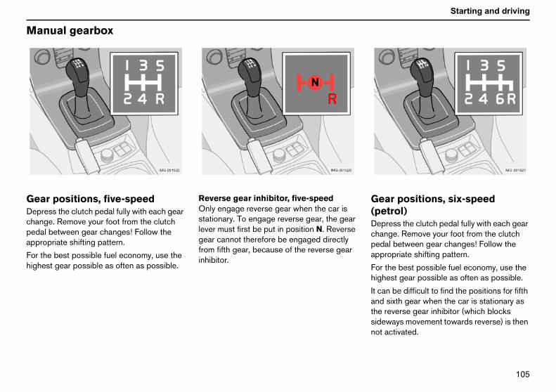
NMR
Starting and driving
Ma
GeDepchapedapp
Forhig
ear positions, six-speedpetrol)epress the clutch pedal fully with each gearhange. Remove your foot from the clutchedal between gear changes! Follow theppropriate shifting pattern.
or the best possible fuel economy, use theighest gear possible as often as possible.
can be difficult to find the positions for fifthnd sixth gear when the car is stationary ase reverse gear inhibitor (which blocks
ideways movement towards reverse) is thenot activated.
nual gearbox
ar positions, five-speedress the clutch pedal fully with each gearnge. Remove your foot from the clutchal between gear changes! Follow theropriate shifting pattern.
the best possible fuel economy, use thehest gear possible as often as possible.
Reverse gear inhibitor, five-speedOnly engage reverse gear when the car isstationary. To engage reverse gear, the gearlever must first be put in position N. Reversegear cannot therefore be engaged directlyfrom fifth gear, because of the reverse gearinhibitor.
G(Dcpa
Fh
Itathsn

NMS
Starting and driving
Ma
Re(peOnsta
everse gear inhibitor, six-speediesel)nly engage reverse gear when the car is
tationary. To engage reverse gear, press theear lever to the left past the spring-loadedhibitor.
nual gearbox
verse gear inhibitor, six-speedtrol)ly engage reverse gear when the car istionary.
Gear positions, six-speed(diesel)Depress the clutch pedal completely for eachgear change. Remove your foot from theclutch pedal between gear changes. Followthe indicated gear pattern. For optimum fueleconomy use the highest possible gear asoften as possible.
R(dOsgin
Important!The spring-loaded inhibitor can be forcedwhen engaging 1st or 2nd gear if youapply too much pressure to the left whenchanging gear. This can lead to reversebeing engaged when driving forwards.

NMT
Starting and driving
Au
CoWhchato tturegeaeng
NOatuspenor
KicWhwayregimmdow
If thdowcha
Kicatio
Toprowh
Thema
isengaging shiftlockcertain cases, it may be necessary to movee car when it is not driveable, for example ife battery is flat. Proceed as follows to movee car:
There is a small cover behind P-R-N-D onthe gear selector panel. Open the rearedge.Insert the key blade from the remotecontrol. Press down and hold the keyblade. The gear selector can now bemoved out of the P position.
tomatic gearbox
ld starten starting in low temperatures, the gearnges can sometimes feel hard. This is duehe gearbox oil’s viscosity at low tempera-s. To minimise engine emissions, therbox shifts up later than normal when theine is started at low temperatures.
TE! Depending on the engine temper-re when the engine is started, the idleed after a cold start may be higher thanmal for certain engine types.
k-downen the accelerator pedal is pressed all theto the floor, beyond the position normally
arded as full acceleration, a lower gear isediately engaged. This is known as kick-n.
e accelerator is released from the kick-n position, the gearbox automatically
nges up.
k-down is used when maximum acceler-n is needed, such as for overtaking.
prevent overrevving, the gearbox controlgram has a protective downshift inhibitorich prevents the kick-down function.
kick-down function cannot be used innual gear position (Geartronic).
Safety systemsCars with an automatic gearbox have specialsafety systems:
KeylockTo remove the ignition key, the gear selectormust be in the P position. The key is locked inall other positions.
Parking position (P)Stationary car with engine running:
– Hold your foot on the brake pedal whenmoving the gear selector to anotherposition.
Electric gear inhibitor – ShiftlockParking position (P position)To be able to move the gear selector from theP position to other gear positions, the ignitionkey must be in position II and the brake pedalmust be depressed.
Shiftlock - Neutral (N position)If the gear selector is in the N position and thecar has been stationary for at least threeseconds (irrespective of whether the engineis running) then the gear selector is locked inthe N position.
NOTE! To be able to move the gear selectorfrom the N position to another gear position,the brake pedal must be depressed and theignition key must be in position II.
DInththth
–
–

NMU
Starting and driving
Au
MeinhThebetwithbut
Preforw
– Reversehe car must be stationary when R iselected.
– Neutralis the neutral position. No gear is engaged
nd the engine can be started. Apply thearking brake when the car is stationary withe gear selector is in position N.
– Driveis the normal driving position. Shifting up
nd down between the different gearboxtios takes place automatically based on thevel of acceleration and speed. The carhould be stationary when the gear lever isoved from position R to position D.
anual positionso move from the automatic driving positionto a manual position, move the gear
elector to position M. To go from position Mthe automatic driving position D, move the
elector to position D.
hile drivinghe manual gearshift mode can be selectedt any time while driving. The engaged gear iscked until you choose another gear.
the gear selector is moved to – (minus) thear changes down a gear and engine brakest the same time as the accelerator pedal is
tomatic gearbox
chanical gear selectoribitorgear selector can be moved freely
ween N and D. Other positions are lockeda latch that is released with the inhibitor
ton on the gear selector.
ss the inhibitor button to move the leverard or back between R, N and D.
Automatic gear positionsP – Parking positionSelect position P when you wish to start theengine or park the car.
NOTE! The brake pedal must be depressedto engage the P position.
The gearbox is mechanically blocked when Pposition is engaged. Always apply theparking brake when parking the car.
RTs
NNapth
DDaralesm
MTDstos
WTalo
Ifca
Important!The car must be stationary when the P isselected.

NMV
Starting and driving
rele+ (
Thecom
NOfun
•
•
ased. If the gear selector is moved toplus) the car changes up a gear.
selected gear is indicated in thebined instrument panel (see page 38).
TE! Geartronic contains two safetyctions:
Geartronic does not permit downshifting/kick-down which would result in anengine speed high enough to damage theengine. Nothing happens if the driver triesto shift down in this way. The original gearremains engaged.Geartronic automatically shifts down ifthe driver allows the speed to decreaselower than a level suitable for the selectedgear, in order to avoid jerking and stalling.
W – WinterThe W button by the gearselector engages and disen-gages thewinter programmeW. The symbol W is shownin the combined instrumentpanel when the winter
programme is activated.
The winter programme starts the gearbox in ahigher gear to facilitate starting off onslippery surfaces. The lower gears are onlyactivated with kick-down when the winterprogramme is engaged.
The W programme can only be selected inposition D.

NNM
Starting and driving
Al
AllAll-
All-whautreaclutpaithe
Undof p
All-sno
l-wheel drive
-wheel drive – AWDwheel drive is always engaged.
wheel drive means that all four roadeels are driven at the same time. Power isomatically distributed between front andr wheels. An electronically controlledch system distributes the power to ther of wheels that grips best. This providesbest traction and prevents wheel spin.
er normal driving conditions, the majorityower is transmitted to the front wheels.
wheel drive improves driving safety in rain,w and icy conditions.

NNN
Starting and driving
Br
BrIf thengpretheprefeethemobra
NOoff,rep
Br
circbrasofpedbra
sing engine braking more efficiently andquires the foot brake for only brief periods.
ear in mind that driving with a trailer puts andditional load on the car’s brakes.
nti-lock braking system (ABS)The anti-lock braking system (ABS)prevents the wheels from locking upunder braking.This means the ability to steer is
aintained and it is easier to swerve to avoidhazard, for example.
fter the engine has been started, the ABSill perform a brief self-test at a speed ofbout 20 km/h. This can be felt and heard asulses in the brake pedal.
o get the most out of the ABS:
Press brake pedal with full force. Pulseswill be felt.Steer the car in the direction of travel. Donot release the pressure on the pedal.
ractice braking with the ABS system in aaffic-free area and in different weatheronditions.
he ABS symbol lights up:
for about two seconds when the car isstarted if the ABS is disengaged due to afault.
ake system
ake servoe car is rolling or is being towed with theine turned off, the brake pedal must bessed about five times harder than whenengine is running. If the brake pedal isssed when the engine is started, you willl the pedal drop. This is normal and due tobrake servo becoming active. This may bere noticeable if the car has emergencyke assistance (EBA).
TE! If braking with the engine switchedpress the brake pedal sharply once, noteatedly.
ake circuitsThis symbol lights if a brake circuit isnot working.
If a fault should occur in one of theuits, it is still possible to brake the car. Theke pedal will travel further and may feelter than normal. Harder pressure on theal is needed to produce the normalking effect.
Dampness can affect brakingcharacteristicsBrake components become wet when the caris driven in heavy rain, through pools of wateror when the car is washed. This may alterbrake pad friction characteristics so thatthere is a delay before braking effect isnoticed.
Press the brake pedal lightly from time to timeif driving for long stretches in rain or slushysnow, as well as after setting off in very dampor cold weather. This warms up the brakingsurfaces and dries off any water. It is alsorecommended to do this before parking thecar for a long period in such weather condi-tions.
If the brakes are used heavilyWhen driving in the Alps or other roads withsimilar characteristics, the car’s brakes areheavily loaded even if the brake pedal is notbeing depressed especially hard.
Because speed is often low, the brakes arenot cooled as effectively as when driving onflat roads at higher speed.
So as not to overload the brakes, shift downwhen driving downhill instead of using thefoot brake. Use the same gear drivingdownhill as you would use driving uphill. This
ure
Ba
A
ma
Awap
T
•
•
Ptrc
T
•
WARNING!The brake servo only works when theengine is running.

NNO
Starting and driving
Br
Em(Emsudprosenregdepoffsuspedand
IfarocthcawchIfthfuThbe
ake system
ergency brake assistance – EBAergency brake assistance) In case ofden braking, full-strength braking isvided instantaneously. The EBA functionses when heavy braking is underway byistering how quickly the brake pedal isressed. Continue braking without easing
on the brake pedal. The function ispended when the pressure on the brakeal eases. This function is always activecannot be disengaged.
WARNING!the BRAKE and ABS warning symbolse lit at the same time, a fault may havecurred in the brake system. If the level ine brake fluid reservoir is normal, driverefully to the nearest authorised Volvo
orkshop to have the brake systemecked.the brake fluid is under the MIN level ine brake fluid reservoir, do not driverther before topping up the brake fluid.e reason for the loss of brake fluid mustinvestigated.

NNP
Starting and driving
St
Whtheatioamalloto o
Theanddyn(DS
TraThepowdrivspitracto dpulis wfuncan
TC/DSTC buttonhe STC/DSTC button in the centre consoleused to suppress or reactivate the system.hen the LED in the button is lit, the systemactive. The LED in the button goes outhen the stability system has beenuppressed. Other functions are notffected.
OTE! To suppress the STC or DSTCnction, the button must be pressed and
eld for at least half a second. The LED in theutton goes out and STC/DSTC SPINONTROL OFF appears on the informationisplay. The system is automatically activatedvery time the engine is started.
Fusy
1
TSA
ability system
en the system is in action, it may seem likecar does not respond normally to acceler-n. This is because the system detects theount of friction on the road surface andws the different stability system functionsperate.
car is either equipped with the stabilitytraction control system (STC) - or the
amic stability and traction control systemTC).
ction Control (TC)Traction Control function transferser from the spinning drive wheel to the
e wheel which has grip by braking thenning drive wheel. To increase forwardtion in this situation, it may be necessaryepress the accelerator more than usual. A
sing sound is heard when Traction Controlorking. This is completely normal. The TC
ction is most active at low speeds. Itnot be deactivated.
Spin Control (SC)The Stability Control function prevents thedrive wheels from slipping during acceler-ation. This improves road safety on slipperysurfaces. Under certain conditions, such aswhen driving with snow chains or in deepsnow or sand, it may be beneficial todeactivate the SC function to increasetraction. This is done with the STC/DSTCbutton.
Active Yaw Control (AYC)The Active Yaw Control function automati-cally brakes one or more wheels to stabilisethe car in the event of a skid. If the brakepedal were to be depressed in this situation,it would feel more rigid than usual and apulsing sound would be heard.
The AYC function is always active and cannotbe deactivated.
STisWiswsa
NfuhbCde
nction/stem
STC DSTC1
. Option on certain markets.
C X XC X XYC X

NNQ
Starting and driving
St
Syins
tracpre
withtemtem
Autplaretu
ability system
mbols on the combinedtrument panel
The symbol lights and goesout again after about2 secondsThe symbol is lit for a systemcheck when the car is started.
Flashing warning symbolThe SC function is operating toprevent the car’s drive wheels fromspinning. The TC function isoperating to improve the car’s
tion. The AYC function is operating tovent skidding.
The information symbolcomes on and stays litTRACTION CONTROLTEMPORARILY OFF is shown inthe information display together
the symbol. The TC function has beenporarily reduced due to too high brakeperature.
omatic reactivation of the function takesce when the brake temperature hasrned to normal.
The information symbolcomes on and stays litANTI-SKID SERVICE REQUIREDappears on the information displaytogether with the symbol. The STC
or DSTC system has been switched offbecause of a fault.
– Stop the car in a safe place and turn offthe engine.
– Restart the engine.– If the warning symbol remains lit, drive to a
workshop to have the system checked.
WARNING!Suppressing the STC or DSTC systemmay alter the driving characteristics of thecar. Always take care when cornering anddriving in slippery conditions.

NNR
Starting and driving
Pa
Par
GeParpardet
Thecombeh
Theabodisthespe
activating and reactivatinge parking assistancee parking assistance can be deactivated byssing EXIT on the control panel, see page. "Park Assist deactivated Enter toivate" will appear on the audio display. Therking assistance can be reactivated byssing ENTER on the control panel. "Park
sistance active Exit to deactivate" will thenpear on the audio display.
nt parking assistancee front parking assistance is active ateds of below 15 km/h, even during
ersing.
e signal comes from the frontdspeakers.
ar parking assistancear parking assistance is activated whenerse gear is engaged. If the system isitched off, the text "Park Assist deactivatedter to activate" will appear on the display asn as reverse gear is engaged.
e signal comes from the rear loudspeakers.
ult indicatorThe information symbol comeson and stays litPARK ASSIST SERVICEREQUIRED is shown on the infor-
tion display in the centre of the combinedtrument panel together with the symbol.
1
rking assistance (option)
king assistance front and rear.
neralking assistance is used as an aid toking. A signal indicates the distance to aected object.
frequency of the signal increases as youe closer to an object1 in front of orind the car.
tone becomes constant at a distance ofut 30 cm. If there are objects within this
tance both behind and in front1 of the car,signal alternates between front and rearakers.
If the volume of another sound source fromthe audio system is high, this is automaticallylowered.
The system is always active when the car isstarted and the text message "Park Assistactive Exit to deactivate" appears on theaudio display.
Front parking assistanceThe distance covered to the front of the car isabout 0.8 m.
Front parking assistance cannot becombined with extra lights because thesensors are affected by the extra lights.
Rear parking assistanceThe distance covered to the rear of the car isabout 1.5 m.
NOTE! The system must be deactivatedwhen driving with a trailer, bike carrier on thetowbar or the like as they would trigger thesensors.
Rear parking assistance is deactivatedautomatically when towing a trailer if a Volvogenuine trailer cable is used.
DethThpre63actpapreAsap
FroThsperev
Thlou
ReRerevswEnsoo
Th
Fa
mains
. Provided that the parking assistanceis mounted both front and rear.
WARNING!Parking assistance does not relinquish thedriver’s own responsibility during parking.The sensors have blind spots whereobjects cannot be detected. Be aware ofchildren and animals near the car.

NNS
Starting and driving
Pa
Par
CleTheenswith
Thesno
rking assistance (option)
king assistance sensors.
aning the sensorssensors must be cleaned regularly to
ure that they work properly. Clean themwater and car shampoo.
sensors can react if covered by ice andw.

NNT
Starting and driving
To
NestaJumbatDo
ToFinbef
–
–
Au–Ma––
Dofas
ImBca
wing and recovery
ver tow the car to bumprt itp start the car with a donor battery if the
tery is flat and the engine does not start.not bump start the car.
wingd out the highest legal speed for towingore towing the car.
Turn the ignition switch to position II andunlock the steering lock so that the carcan be steered, see page 102.The ignition key must remain in position IIwhile the car is being towed.tomatic gearbox:Move the gear selector to position N.nual gearbox:Move gear lever into neutral.Ensure the towrope is always taut toavoid violent jerks. Keep your foot on thebrake pedal.not tow cars with an automatic gearboxter than 80 km/h nor further than 80 km.
RecoveryCars with an automatic gearbox should not, ifpartly lifted, be towed at more than 80 km/h.They should not be towed further than 80 km.
portant!ump starting the car can damage thetalytic converter.
WARNING!The steering lock stays in the position itwas in when the power was cut off. Thesteering lock must be unlocked beforetowing.The ignition key must be in position II.Never remove the ignition key from theignition switch while driving or when thecar is being towed.
WARNING!The brake servo and power steering donot work when the engine is switched off.The break pedal must be pressedabout five times harder than normal, andthe steering will be considerable heavierthan normal.
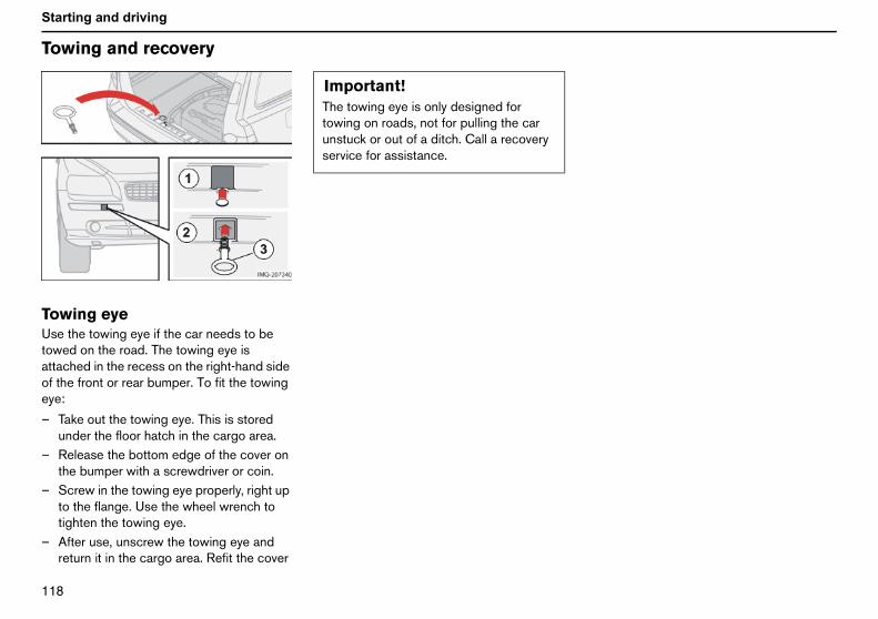
NNU
Starting and driving
To
ToUsetowattaof teye
–
–
–
–
wing and recovery
wing eyethe towing eye if the car needs to be
ed on the road. The towing eye isched in the recess on the right-hand sidehe front or rear bumper. To fit the towing:
Take out the towing eye. This is storedunder the floor hatch in the cargo area.Release the bottom edge of the cover onthe bumper with a screwdriver or coin.Screw in the towing eye properly, right upto the flange. Use the wheel wrench totighten the towing eye.After use, unscrew the towing eye andreturn it in the cargo area. Refit the cover
Important!The towing eye is only designed fortowing on roads, not for pulling the carunstuck or out of a ditch. Call a recoveryservice for assistance.

NNV
Starting and driving
St
StIf thcansepAlwjumspa
Whsteexp
–––
WARNING!The battery can generate oxyhydrogengas, which is highly explosive. One spark,which can be generated if you connect thejump leads incorrectly, is sufficient tomake the battery explode.The battery contains sulphuric acid, whichcan cause serious burns. If the acidcomes into contact with eyes, skin orclothing, flush with large quantities ofwater. If acid splashes into the eyes, seekmedical attention immediately.
art assistance
arting with a donor batterye battery in the car has become flat, you"borrow" electric current from either aarate battery or the battery in another car.ays make sure the crocodile clips on thep leads are attached securely to eliminaterks during the start attempt.
en jump starting the car, the followingps are recommended to avoid risk oflosion:
Turn the ignition key to position 0.Ensure that the other battery is 12 volt.If the donor battery is in another car,switch off the engine in the other car and
ensure that the cars do not touch oneanother.
– Connect the red jump lead between thepositive terminal on the donor battery(1+) and the one in your car (2+).
– Connect one end of the black jump leadto the donor battery’s negativeterminal (3–).
– Connect the other end of the black jumplead to the earthing point (4–) by the left-hand strut tower.
– Start the engine of the "donor car". Letthe engine run a few minutes at a speedslightly higher than idle 1500 rpm.
– Start the engine of the car with the flatbattery.
– Remove the jump leads, first the blackand then the red. Ensure that neither endof the black jump lead comes into contactwith the battery’s positive terminal or thecrocodile clip on the red jump lead.
Do not touch the crocodile clips during thestart procedure. This could cause sparking.

NOM
Starting and driving
Dr
GeThesorthehitcthecapof p
If thfacnec
•
•
•
•
•
a car with an automatic gea rbox andattached trailer are parked. Always usethe parking brake.
railer weightsee page 209 for permitted trailer weights.
OTE! The stated maximum permitted trailereights are those permitted by Volvo.ational vehicle regulations can further limitailer weights and speeds. Towbars can beertified for higher towing weights than thear can actually tow.
1
WARNING!Follow the stated recommendations fortrailer weights. Otherwise, the rig may bedifficult to control during evasivemanoeuvres and braking.
iving with a trailer
neralload capacity is affected by extra acces-
ies mounted on the car, such as a towbar,load on the towball (75 kg with trailerhed), load carriers and roof box, as well aspassengers’ combined weight. The loadacity of the car is reduced by the numberassengers and their weight.
e towing bracket is mounted at the Volvotory, the car is delivered with theessary equipment for driving with a trailer.
The car’s towing bracket must be of anapproved type.If the towbar is retrofitted, check with yourVolvo dealer that the car is fully equippedfor driving with a trailer.Distribute the load on the trailer so thatthe weight on the towing bracket followsthe specified maximum towball load.Increase the tyre pressure to the recom-mended pressure for a full load. Seepage 135 for the location of the tyrepressure label.Clean the towbar regularly and grease thetowball1.
• Do not tow a heavy trailer when the car isbrand new. Wait until it has been driven atleast 1000 km.
• The brakes are loaded much more thanusual on long and steep downhill slopes.Downshift to a lower gear and adjust yourspeed.
• The engine is loaded more heavily thanusual when driving with a trailer.
• The engine and gearbox can overheat ifthe car is driven with a heavy load in hotweather. If the temperature gauge for theengine’s cooling system goes into the redzone, stop and let the engine idle for afew minutes. The gearbox respondsthrough a built-in protection system. Seethe message on the information display. Ifthe car overheats, the air conditioningmay be switched off temporarily.
• In the interests of safety, speed should berestricted to 80 km/h, even if the laws ofcertain countries allow for higher speeds.
• The gear selector should be in the parkingposition P when a car with an automaticgearbox and attached trailer are parked.Always use the parking brake.
• Place chocks under the wheels to preventthe car from rolling when parked on a hillwith trailer attached. The gear selectorshould be in the parking position P when
TS
NwNtrcc
. Does not apply to the towball if usinga stabiliser hitch.

NON
Starting and driving
Aua tPa––
Sta–
–Ste•
•
•
DiedriIf thwebecapis tair
tomatic gearbox, driving withrailerrking on a hill:Apply the parking brake (handbrake).Move gear selector to the parkingposition P.rting on a hill:
Move the gear selector to drivingposition D.Release the parking brake (handbrake).ep inclines:
Select an appropriate manual gearposition when climbing steep inclines orat low speeds. This prevents the gearboxfrom changing up and keeps the gearboxoil cooler.Do not use a higher manual gear than theengine can "handle". It is not alwayseconomical to drive in high gears.Avoid driving with a trailer on inclines ofmore than 15 %.sel engine with manual gearbox,
ving with a trailere car is driven with a heavy load in hot
ather then the engine cooling fan shouldreplaced with a cooling fan with greateracity than the fan fitted as standard. This
o avoid temporary shut down of the car'sconditioning and temporary reduction in
engine torque. Consult your Volvo dealer forinformation regarding your car'sspecifications.

NOO
Starting and driving
To
ToTheregdamthe
If thtowmu
NOafte
Bto
IftoFotoThthCgr
wing equipment
wbarstowball must be cleaned and greased
ularly. If a towball hitch with vibrationper is used, it is not necessary to greasetowball.
e car is equipped with a detachablebar, the towball mounting instructionsst be followed carefully, see page 124.
TE! Always take off the towball sectionr use. Keep it in the cargo area.
Trailer cableAn adapter is required if the car’s towbar has13 pin electrics and the trailer has 7 pinelectrics. Use an adapter cable approved byVolvo. Make sure the cable does not drag onthe ground.
WARNING!e sure to attach the trailer’s safety cablethe correct place.
WARNING!the car is fitted with a Volvo detachablewbar:llow the assembly instructions for thewball section carefully.e towball section must be locked withe key before setting off.heck that the indicator window showseen.
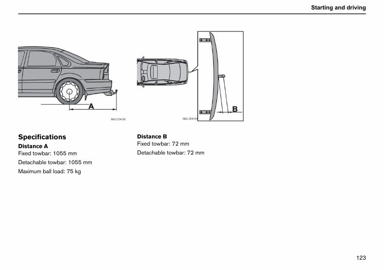
NOP
Starting and driving
SpDisFixe
Det
Ma
ecificationstance Ad towbar: 1055 mm
achable towbar: 1055 mm
ximum ball load: 75 kg
Distance BFixed towbar: 72 mm
Detachable towbar: 72 mm

NOQ
Starting and driving
De
Fit–
Check that the indicator window (3)shows red.If the window does not show red, pressin (1) and turn the locking wheelanticlockwise (2) until you hear a click.
tachable towbar
ting the towballRemove the guard plug.
– Ensure that the mechanism is in theunlocked position by turning the keyclockwise.
–

NOR
Starting and driving
– Turn the key anticlockwise to the lockedposition. Remove the key from the lock.
Insert the towball section until your hear aclick.
– Check that the indicator window showsgreen.
–

NOS
Starting and driving
De
NOsectowmuwith
tachable towbar
TE! Check that the towball section isure by pulling it up, down and back. If theball section is not fitted correctly then itst be removed and refitted in accordance
the previous steps.
NOTE! The trailer’s safety cable must beattached to the attachment on the towbar.

NOT
Starting and driving
Re–
Turn the locking wheel down fully, until itcomes to a stop. Hold it in this positionwhile pulling the towball rearward andupward.
moving the towballInsert the key and turn it clockwise to theunlocked position.
– Push in the locking wheel and turn itanticlockwise until you hear a click.
–

NOU
Starting and driving
De
–
tachable towbar
Insert the guard plug.

NOV
Starting and driving
Lo
GeThesorthehitctheloanum
LoStowhgeaoutthecarand
Plafron
•
•
oad carrierso avoid damaging the car and for maximumossible safety while driving, it is recom-ended to use load carriers speciallyesigned for your car by Volvo.
arefully follow the mounting instructionsupplied with the carriers.
Check periodically that the load carriersand load are properly secured. Lash theload securely with retaining straps.Distribute the load evenly over the loadcarriers. Put the heaviest objects at thebottom.The size of the area exposed to the wind,and therefore fuel consumption, increasewith the load’s size.Drive gently. Avoid quick accelerations,heavy braking and taking curves hard.
Thdeho
WARNING!Load no more than 75 kg on the roof,inclusive of the load carriers and any roofbox.The car’s centre of gravity and drivingcharacteristics are altered by roof loads.
ading
neralload capacity is affected by extra acces-
ies mounted on the car, such as a towbar,load on the towball (75 kg with trailerhed), load carriers and roof box, as well aspassengers’ combined weight. The car’s
d carrying capacity is reduced by theber of passengers and their weight.
ading the cargo areap the engine and apply the parking brakeen loading or unloading long objects. Ther lever or gear selector can be knockedof position by long loads, which could setcar in motion. To increase the size of the
go area, the head rests can be removedthe seats folded down, see page 84.
ce the load firmly against the backrest int.
The head rests can be removed so thatthey are not damaged.Put wide loads in the centre.
• Heavy objects should be placed as lowas possible. Avoid placing heavy loads ona lowered backrest.
• Cover sharp edges with something soft toavoid damaging the upholstery.
• Secure all loads to the load retainingeyelets with straps or web lashings.
LTpmd
Cs
•
•
•
•
WARNING!e car’s driving characteristics changepending on how heavily it is loaded andw the load is distributed.
WARNING!A loose object weighing 20 kg can, in afront-on collision at a speed of50 km/h, carry the impact of an itemweighing 1000 kg.
WARNING!Never load cargo above the backrest.The protection provided by the inflatablecurtain in the headlining may be compro-mised or eliminated by high loads.Always secure the load. During heavybraking the load may otherwise shift,causing personal injury.

NPM
Starting and driving
Ad
A. HB. R
CorigTheto apat
i-Xenon lights
i-Xenon headlampshe headlamp control should be inosition (A) for left-hand traffic andosition (B) for right-hand traffic.
WARNING!On cars with Bi-Xenon headlamps, allwork on the lights should be carried out atan authorised Volvo workshop.Bi-Xenon headlamps must be handledwith extreme care due to the high-voltageunit.
justing headlamp pattern
eadlamp pattern for left-hand trafficight-hand traffic
rrect light pattern for left orht-hand trafficheadlamps’ projection can be adjusted
void dazzling other motorists. The correcttern will also better illuminate the verge.
Halogen lights
Halogen headlampsThe headlamp control should be inposition (A) for left-hand traffic andposition (B) for right-hand traffic.
B
BTpp

NPN
Wheels and tyresGeneral 132Tyre pressure 135Changing wheels 136
Warning triangle and spare wheel 137Removing wheels 139Emergency puncture repair 141

NPO
Wheels and tyres
Ge
DrThechatyrefor
Whsamalsowhprelab
DeTheExa205
SpThethadiffregthewith
yre ageven if tyres have a theoretical lifespan of upten years, it is not recommended to drive
n tyres which are more than six years old.
2055
R1691W
neral
iving characteristics and tyrestyres greatly affect the car’s driving
racteristics. The type of tyre, dimensions,pressure and speed rating are important
how the car performs.
en changing tyres, ensure that tyres of thee type and dimensions, and preferablythe same make, are fitted to all four
eels. Follow the recommended tyressures specified on the tyre pressureel, see page 135.
signation of dimensionsdimensions are stated on all car tyres.
mple:/55R16 91 W.
eed ratingscar is approved as a whole, which means
t dimensions and speed ratings must noter from those specified on the vehicle’sistration document. The only exception tose conditions is winter tyres (both those
metal studs and those without). If such a
tyre is chosen, the car must not be drivenfaster than the speed rating of the tyre (forexample, class Q can be driven at a maximumof 160 km/h).
Remember that traffic regulations determinehow fast a car can be driven, not the speedclass of the tyres.
Note! Maximum permitted speeds indicated.
New tyresTyres are perishable. After afew years they begin toharden at the same time asthe friction capacity/charac-teristics gradually deteri-orate. Therefore aim to get
as fresh tyres as possible when you replacethem. This is especially important with regardto winter tyres. The week and year ofmanufacture are stated with four digits, forexample 1502. The tyre in the illustration wasmanufactured in week 15 of 2002.
TEtoo
5 Section width (mm)Ratio between section height andwidth (%)Radial plyRim diameter in inches (")Tyre load index (in this case 615 kg)Speed rating (in this case 270 km/h)
Q 160 km/h (used only on wintertyres)
T 190 km/hH 210 km/hV 240 km/hW 270 km/hY 300 km/h

NPP
Wheels and tyres
TyrTrebansidweremthetyregrip
WiVolculatyreloc
pace between the brake disks and theheels is too small.
Important!Use Volvo genuine snow chains orequivalent chains designed for the carmodel, and tyre and rim dimensions.Consult an authorised Volvo workshop
es with tread wear indicatorsad wear indicators are narrow treadlessds across the width of the tread. On the
e of the tyre are the letters TWI (treadar indicator). When only 1.6 mm of treadains, this band is clearly visible. Changetyres as soon as possible. Remember thats with little tread depth provide very poorin rain and snow.
nter tyresvo recommends winter tyres with parti-r dimensions. These are stated on thepressure label, see page 135 for its
ation. The tyre dimensions are dependent
on the engine variant. When driving on wintertyres, these must be fitted to all four wheels.
NOTE! Ask a Volvo dealer which rim and tyretypes are most suitable.
Studded tyresStudded winter tyres should be run in gentlyfor 500-1000 km so the studs settle properlyinto the tyre. This gives the tyre, andespecially the studs, a longer lifespan.
NOTE! The legal provisions for the use ofstudded tyres vary from country to country.
Tread depthRoad conditions with ice, slush and lowtemperatures place considerably higherdemands on tyres than summer conditions. Itis therefore not recommended to drive onwinter tyres that have a tread depth of lessthan four millimetres.
Snow chainsSnow chains may only be used on the frontwheels. This also applies to all-wheel-drivecars.
NOTE! Never drive faster than 50 km/h withsnow chains. Avoid driving on bare ground asthis wears out both the snow chains andtyres. Never use quick-fit snow chains as the
sw

NPQ
Wheels and tyres
Ge
Sta
RimOnbysordepste85wre
emporary sparehe spare wheel1 is only intended to be usedr the short time it takes to get the ordinaryheel replaced or repaired. Replace thepare wheel as soon as possible with aormal wheel. The car’s handling may beltered by the use of the spare wheel.
ever drive faster than 80 km/h with a spareheel on the car.
ImTh8nu
1. Certain variants and markets
Important!The car must never be driven fitted withmore than one temporary spare wheel.
neral
ndard (1) and bulge acorn (2) wheel nuts
s and wheel nutsly use rims that are tested and approvedVolvo and which are Volvo genuine acces-ies. There are two types of wheel nut,ending on whether the rims are made of
el or aluminium. Tighten the wheel nuts toNm. Check the torque with a torquench.
Steel rims – standard wheel nuts (1)Steel rims are normally mounted with thestandard wheel nuts, but the bulge acornvariety may also be used.
Aluminium rims – bulge acorn wheelnuts (2)Only use the bulge acorn variety of nuts withaluminium rims. These differ markedly fromother nut types as they have a rotating conicalwasher.
NOTE! These nuts may also be used withsteel rims.
Locking wheel nutsLocking wheel nuts can be used on bothaluminium and steel rims. If steel rims withlocking nuts are used in combination withwheel covers, the locking wheel nut shouldbe mounted on the bolt nearest the air valve.Otherwise the wheel cover cannot be fittedto the rim.
TTfowsna
Nw
portant!e wheel nuts should be tightened to
5 Nm. Overtightening can damage thets and the bolts.
WARNING!Never use standard nuts for aluminiumrims. The wheels can come loose.

NPR
Wheels and tyres
Ty
ReThefueshocon
re pressure
commended tyre pressuretyre pressure decal on the inside of the
l filler flap shows what pressure the tyresuld have with different load and speedditions.
Checking the tyre pressureCheck the tyre pressure regularly. Thecorrect tyre pressure is shown in the tyrepressure table. The stated tyre pressuresrefer to cold tyres. (Cold tyres mean the tyresare the same temperature as the ambienttemperature.)
Driving with the wrong tyre pressureadversely affects the car’s driving characte-ristics and can increase tyre wear. After just afew kilometres of driving, the tyres warm upand the pressure increases. Therefore airshould not be released if the pressure ischecked when the tyres are warm. Howeverthe pressure should be increased if it istoo low.

NPS
Wheels and tyres
Ch
Therota
SuWhchasidexatreain omarotalifesbetbetvercarforc
anging wheels
arrow shows the tyre’s direction oftion.
mmer and winter wheelsen summer and winter wheels arenged they should be marked with which
e of the car they were mounted on, formple L for left and R for right. Tyres with ad pattern which are designed to only turnne direction have the direction of rotationrked with an arrow. The tyre should alwayste in the same direction throughout itspan. Tyres should only be switched
ween front and rear positions, neverween left and right-hand sides, or vicesa. If the tyre is mounted incorrectly, the’s braking characteristics and capacity toe rain, snow and slush out of the way are
adversely affected. Tyres with the greatesttread depth should always be fitted to therear of the car (to decrease the risk ofskidding).
Wheels should be stored lying down orhanging up, and not standing up.
Contact an authorised Volvo workshop if youare uncertain about tread depth.

NPT
Wheels and tyres
W
WaThethe
Folwara s
–
–Enspro
arning triangle and spare wheel
rning trianglewarning triangle is fitted on the inside ofboot lid attached with two clips.
low the regulations for the use of aning triangle. Place the warning triangle in
uitable place with regard to the traffic.
Undo the case containing the warningtriangle, it is attached with Velcro. Takethe warning triangle out of the case.Lower the warning triangle’s support legs.ure the warning triangle and its case areperly secured in the cargo area after use.

NPU
Wheels and tyres
W
SpTheThechaalw
Thefou
Tak–
––
arning triangle and spare wheel
are wheel and jackcar’s original jackoriginal jack should only be used for
nging wheels. The jack’s thread shouldays be well greased.
spare wheel, jack and wheel spanner arend under the floor in the cargo area.
ing out the spare wheel:Fold the rear edge of the floor matforward.Release the spare wheel and lift it out.Take out the jack and the wheel spanner.
Putting the spare wheel and jack intothe cargo area:– Wind the jack to halfway (1). The marking
on the plate (2) should line up with themarking on the arm (3) so that the jackcan fit lying down in the holder.
– Fold in the handle (4) and place the wheelspanner (5) on the jack.
– Put the jack back (1) in the hole on theright (6). Fasten the spare wheel (7) inthe hole on the left (8).
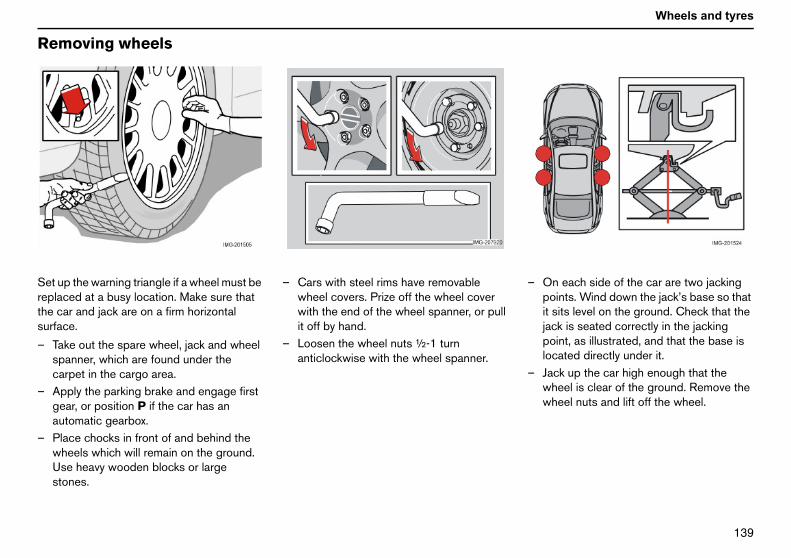
NPV
Wheels and tyres
Re
Setrepthesur
–
–
–
On each side of the car are two jackingpoints. Wind down the jack’s base so thatit sits level on the ground. Check that thejack is seated correctly in the jackingpoint, as illustrated, and that the base islocated directly under it.Jack up the car high enough that thewheel is clear of the ground. Remove thewheel nuts and lift off the wheel.
moving wheels
up the warning triangle if a wheel must belaced at a busy location. Make sure thatcar and jack are on a firm horizontal
face.
Take out the spare wheel, jack and wheelspanner, which are found under thecarpet in the cargo area.Apply the parking brake and engage firstgear, or position P if the car has anautomatic gearbox.Place chocks in front of and behind thewheels which will remain on the ground.Use heavy wooden blocks or largestones.
– Cars with steel rims have removablewheel covers. Prize off the wheel coverwith the end of the wheel spanner, or pullit off by hand.
– Loosen the wheel nuts ½-1 turnanticlockwise with the wheel spanner.
–
–

NQM
Wheels and tyres
Re
Fit–
––
–
–
NonPraEorth
moving wheels
ting the wheelClean the contract surfaces on the wheeland hub.Put on the wheel. Tighten the wheel nuts.Lower the car so that the wheel cannotrotate.Tighten the wheel nuts crosswise. It isimportant that the wheel nuts aretightened properly. Tighten to 85 Nm.Check the torque with a torque spanner.Put on the wheel cover (steel rim).
WARNING!ever crawl under the car when it is raised
the jack.assengers must leave the car when it isised on the jack.nsure that passengers wait with the car -preferably a crash barrier - between
em and the road.

NQN
Wheels and tyres
Em
GeCainstpunbotadjelecan
EmTheintetha(maseatyre
ergency puncture repair
neralrs which do not have a spare wheel areead equipped with an emergencycture repair kit. This kit can be used toh seal the puncture and to check andust the tyre pressure. The kit consists of anctric air compressor and an integratedister with sealing liquid.
ergency puncture repair kitemergency puncture repair kit is only
nded to work as a temporary repair sot the car can be driven a further 200 kmx.) or to the nearest tyre centre. Theling fluid has the ability to effectively seals which have punctures in the tread.
The canister with the sealing fluid should bereplaced before the best-before date hasexpired or after the emergency repair kit hasbeen used. Puncture repair kit replacement,see page 146 for canister replacement.
NOTE! The emergency puncture repair kit isonly intended for sealing tyres with apuncture in the tread.

NQO
Wheels and tyres
Em
Theabitheemlargdam
Thecomfloo
12by tseaeletyre
Takrep–
–
ergency puncture repair
emergency puncture repair kit has limitedlities to seal tyres which have punctures inwall of the tyre. Do not seal tyres with theergency puncture repair kit if they haveer slits, cracks, irregularities or similarage.
emergency puncture repair kit withpressor and tools are found under ther in the cargo area.
V sockets for the compressor are locatedhe centre console in the front, by the reart and in the cargo area. Choose thectrical socket that is nearest the punctured.
ing out the emergency punctureair kit
Fold away the rear edge of the floor matforward.Lift up the emergency puncture repair kit.
WARNING!The sealing fluid may cause irritation if itcomes into direct contact with skin. Inthe case of contact with skin, wash awaythe fluid with soap and water.

NQP
Wheels and tyres
InfSetinfla
–
–
–
–
–
Objects with a volume of up to 50 litrescan be pumped up with the compressor.
WARNING!Inhaling car exhaust fumes can result indanger to life. Never leave the enginerunning in sealed areas or areas that lacksufficient ventilation.
lating tyresup the warning triangle if a tyre must beted in an area close to traffic.
Ensure that the orange switch (2) is inposition 0 and take out the lead (5) andair hose (4) from the sidecompartment (3).Screw the air hose’s valve connection tothe bottom of the thread on the tyre’s airvalve.Connect the lead (5) to one of the car’s12 V sockets.Start the engine. The car must be in awell-ventilated place.Start the compressor by flicking theswitch (2) to position I.
– Pump up the tyre to the pressurespecified on the tyre pressure label.
– Turn off the compressor, the switch (2)should be in position 0. Detach the airhose and unplug the lead. Replace thevalve’s dust cap.
– Put the lead (5) and air hose (4) into theside compartment (3).
– Put the puncture repair kit back under thefloor in the cargo area.
– The compressor should not run for morethan ten minutes at a time. Let it coolafterwards as there is a risk ofoverheating.
–
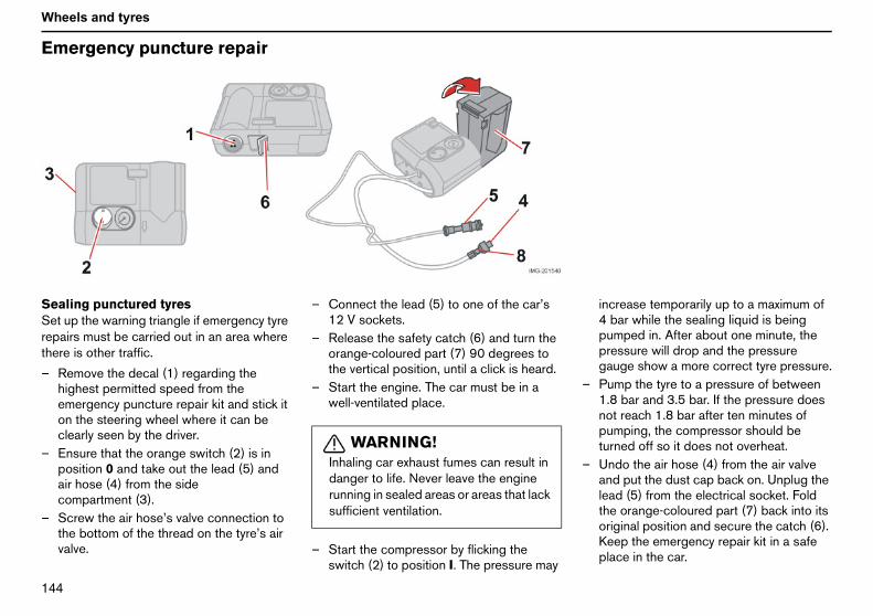
NQQ
Wheels and tyres
Em
SeSetrepthe
–
–
–
increase temporarily up to a maximum of4 bar while the sealing liquid is beingpumped in. After about one minute, thepressure will drop and the pressuregauge show a more correct tyre pressure.Pump the tyre to a pressure of between1.8 bar and 3.5 bar. If the pressure doesnot reach 1.8 bar after ten minutes ofpumping, the compressor should beturned off so it does not overheat.Undo the air hose (4) from the air valveand put the dust cap back on. Unplug thelead (5) from the electrical socket. Foldthe orange-coloured part (7) back into itsoriginal position and secure the catch (6).Keep the emergency repair kit in a safeplace in the car.
ergency puncture repair
aling punctured tyresup the warning triangle if emergency tyre
airs must be carried out in an area wherere is other traffic.
Remove the decal (1) regarding thehighest permitted speed from theemergency puncture repair kit and stick iton the steering wheel where it can beclearly seen by the driver.Ensure that the orange switch (2) is inposition 0 and take out the lead (5) andair hose (4) from the sidecompartment (3).Screw the air hose’s valve connection tothe bottom of the thread on the tyre’s airvalve.
– Connect the lead (5) to one of the car’s12 V sockets.
– Release the safety catch (6) and turn theorange-coloured part (7) 90 degrees tothe vertical position, until a click is heard.
– Start the engine. The car must be in awell-ventilated place.
– Start the compressor by flicking theswitch (2) to position I. The pressure may
–
–
WARNING!Inhaling car exhaust fumes can result indanger to life. Never leave the enginerunning in sealed areas or areas that lacksufficient ventilation.

NQR
Wheels and tyres
–
–NOparuse
–
Yafbem(m
Immediately drive about 3 km, at amaximum speed of 80 km/h, to allow thesealing fluid to seal the tyre well.
Check the tyre pressure again:TE! Do not raise the orange-colouredt (7) when only the compressor is to bed for inflation.
Connect the air hose (4) to the air valveon the tyre. Connect the lead (5) to the12 V power point. Read the pressure on
the compressor. If the tyre pressure isbelow 1.3 bar, the tyre has not been suffi-ciently well sealed. The journey shouldnot be continued under these circums-tances. Contact a tyre centre.
– If the tyre pressure is higher than 1.3 bar,the tyre should be pumped up to thepressure stated on the tyre pressurelabel, see page 135 for its location.Release pressure with the reductionvalve (8) if the tyre pressure is too high.
– Turn off the compressor, the switch (2)should be in position 0. Detach the airhose and unplug the lead. Replace thevalve’s dust cap.
– Put the lead (5) and air hose (4) into theside compartment (3).
– Put the puncture repair kit back under thefloor in the cargo area.
The compressor should not run for more thanten minutes at a time. Let it cool afterwards asthere is a risk of overheating.
NOTE! The canister with sealant and hoseshould be replaced after use.
WARNING!Never stand next to the tyre when thecompressor is running. Be particularlyobservant of the tyre walls. If cracks,irregularities or other damage appears,turn off the compressor immediately.Under these circumstances your journeyshould not continue. Contact anauthorised tyre centre.
WARNING!ou should not drive faster than 80 km/hter the emergency tyre repair kit hasen used. The temporarily sealed tyre
ust be changed as soon as possibleaximum driving distance: 200 km).

NQS
Wheels and tyres
Em
ChcaThechaexphaswithcha
Theriseinst
Check that the seal (7) on the newcanister is not damaged. Screw thecanister into place.Refit the case (3). Check that the case iscorrectly fitted. Screw it on with thescrews (2).Affix the speed label (4) and new datelabel (1) to the tyre repair kit.
reat the removed canister as hazardousaste.
hanging the canister and hose afterse
Undo the two screws (2) on the orange-coloured case (3).
ImRbo
ergency puncture repair
anging the sealing fluidnister
canister of sealing fluid should benged before the best-before date hasired, see date label (1), or after the tyrebeen sealed. After use, the canister (6)holder (8) and air hose (10) should be
nged.
canister can be replaced by an autho-d Volvo workshop or according to theructions.
Changing the canister before thebest-before date has expired– Undo the two screws (2) on the orange-
coloured case (3).– Remove the speed label (4) and date
label (1), and open the safety catch (5).Loosen the case (3) and take it off.
– Unscrew and remove the canister (6).
–
–
–
Tw
Cu–portant!
ead the safety instructions on thettom of the canister.
WARNING!Ensure the compressor is not connectedto the 12 V socket when the canister ischanged.

NQT
Wheels and tyres
–
–
––
–
Chnotcanclic
–
–
Thetrea
Remove the speed label (4) and datelabel (1), and open the safety catch (5).Loosen the case (3) and take it off.Push down the button (8) while turningthe canister (6) and the holder (9)clockwise. Remove them.Pull out the air hose (10).Wipe off remaining sealing fluid with a ragor scrape it away if it is has already dried.Fit a new air hose (10). Check that it isfitted correctly.eck that the seal (7) on the new canister isdamaged. Screw the holder (9) onto theister (6) and turn it anticlockwise until ak is heard.
Refit the case (3). Check that the case iscorrectly fitted. Screw it on with thescrews (2).Affix the speed label (4) and new datelabel (1) to the tyre repair kit.
empty canister and air hose can beted as normal waste.

NQU
Wheels and tyres

NQV
Car careCleaning 150Touching up paintwork 152Rustproofing 153

NRM
Car care
Cl
WaWaUseto c
•
•
•
•
•
•
•
ReWasooche
eaning the upholsteryating spots on fabricpecial cleaning agent, available from yourlvo dealer, is recommended for cleaningfabric upholstery. Other chemicals canair the fire retardant qualities of the uphol-ry.
ating spots on vinyl and plastic partspecial cleaning agent, available from yourlvo dealer, is recommended for cleaningrior vinyl and plastic parts. Do not scrape
rub spots. Do not use strong stainovers.
ating spots on leatherpecial cleaning agent, available from yourlvo dealer, is recommended when cleaningther upholstery. Treat the leather uphol-ry once or twice a year using Volvo’sther care kit. Never use strong solvents.ch products may damage fabric, vinyl andther upholstery.
mportant!harp objects and Velcro may damagee fabric upholstery.
eaning
shing the carsh the car as soon as it becomes dirty.car shampoo. Dirt and road salt can lead
orrosion.
Do not park the car in direct sunshine.Washing a car with hot paintwork cancause permanent paintwork damage.Wash the car in a carwash with wastewater separator.Thoroughly rinse dirt off the underbody ofthe car.Rinse the entire car to remove loose dirt.When using a pressure washer: Makesure that the nozzle of the pressurewasher is not closer than 30 cm to thebodywork. Do not spray directly at thelocks.Wash using a sponge, car shampoo andplenty of lukewarm water.If the dirt is difficult to dislodge, wash thecar using a cold degreasing agent.Dry the car using a clean, soft chamois ora water scraper.Clean the wiper blades with a lukewarmsoap solution or car shampoo.moving bird droppingssh bird droppings off the paintwork asn as possible. Bird droppings containmicals that affect and discolour paintwork
very quickly. This discoloration can only beremoved by a specialist.
Automatic carwashesAlthough an automatic carwash is a quickand easy way to clean the car, it is nosubstitute for a proper hand wash. Thebrushes of an automatic carwash cannotreach all parts. We recommend that new carsare washed by hand for the first few months.
Press the brake pedal lightly from time to timeif driving for long periods in rain or slush. Thisheats and dries the brake pads. You shouldalso do this when you begin driving inextremely damp or cold weather.
ClTreA sVotheimpste
TreA sVointeorrem
TreA sVoleasteleaSulea
WARNING!Always have the engine cleaned by aworkshop. There is a risk of fire if theengine is hot.
WARNING!Always test the brakes after washing thecar to ensure that moisture and corrosiondo not attack the brake pads and reducebraking performance.
ISth

NRN
Car care
CleUsespeyoudry
PoPolor t
Theis abewax
Wabegandwhremfor
Polliquthecon
aning seatbeltswater and a synthetic detergent. A
cial textile cleaning agent is available fromVolvo dealer. Make sure the seatbelt isbefore allowing it to retract.
lishing and waxingish and wax the car if the paintwork is dullo give the paintwork extra protection.
car does not need to be polished until itt least one year old. However, the car canwaxed during this time. Do not polish or
the car in direct sunlight.
sh and dry the car thoroughly before youin polishing or waxing. Clean off asphalttar stains using Volvo tar remover or
ite spirit. More stubborn marks can beoved using fine rubbing paste designedcar paintwork.
ish first with a polish and then wax withid or solid wax. Follow the instructions onpackaging carefully. Many preparationstain both polish and wax.

NRO
Car care
To
PaPairuschedamimmpaiscrand
CoIt isThepro
StBefbeabo
Stir the primer well and apply using a finebrush or matchstick. Apply paint using abrush once the primer is dry.For scratches, proceed as above, butmask around the damaged area to protectthe undamaged paintwork.After a few days, polish the touched-upareas. Use a soft rag and a small amountof lapping paste.
uching up paintwork
intworknt is an important part of the car’stproofing and should therefore becked regularly. To avoid the onset of rust,aged paintwork must be rectifiedediately. The most common types of
ntwork damage are stone chips,atches, and marks on the edges of wings
doors.
lour codeimportant that the correct colour is used.car’s colour code is shown on the
duct decal on the B-pillar. See page 208.
one chips and scratchesore touching up paintwork, the car mustclean and dry and at a temperatureve 15 °C.
Materials• Primer in a can• Paint in a can or touch-up pen• Brush• Masking tapeMinor stone chips and scratchesIf the stone chip has not penetrated to thebare metal and there is an undamaged colourcoat, you can paint straight after cleaning thedamaged area.
If the stone chip has penetrated to thebare metal– Stick a piece of masking tape over the
damaged surface. Then remove the tapeto remove any loose paint.
–
–
–

NRP
Car care
Ru
InsYourusareundantpenintosec
Ma
•
•
ThereqAfteyeatreaVol
stproofing
pection and maintenancer car received a thorough and complete
tproofing at the factory. Parts of the bodymade of galvanised sheet metal. Theerbody is protected by a wear-resistant
i-corrosion compound. And, a thin,etrating rustproofing fluid was sprayedthe members, cavities and closed
tions.
intain the car’s rustproofing.
Keep the car clean. Hose down theunderbody. If using a pressure washer,keep the nozzle at least 30 cm from thepainted surfaces.Regularly check and touch-up therustproofing treatment as necessary.
car’s rustproofing does not normallyuire treatment for approximately 12 years.r that time, it should be treated at three-
r intervals. If the car needs furthertment, please contact an authorised
vo workshop.

NRQ
Car care

NRR
Maintenance and serviceVolvo service 156Self-maintenance 157Bonnet and engine compartment 158
Diesel 159Oils and fluids 160Wiper blades 164
Battery 165Replacing bulbs 167Fuses 173

NRS
Maintenance and service
Vo
VoBefthoin areg
ToposspeBoocarVoltoohig
SpCecarusindevautor pele
olvo Car Corporation will not disclose thetored information without consent. However,olvo Car Corporation may be forced toisclose the information due to national legis-tion. Volvo Car Corporation and itsorkshops may also read and use the infor-ation.
dverse driving conditionshange the engine oil and replace the air andil filters more often than recommended in theervice and Warranty Booklet when driving indverse conditions.
dverse driving conditions include extendederiods of driving:
in a dusty or sandy environment.towing a caravan or trailer.in mountainous regions.at high speeds.at low speeds or idling.short journeys (less than 10 km) at lowtemperatures (below 5 ºC).
ImFoanan
lvo service
lvo service programmeore the car left the factory, it wasroughly test driven. It was checked againccordance with Volvo Car Corporationulations before it was handed over to you.
keep your Volvo as safe and reliable assible, follow the Volvo service programmecified in the Service and Warrantyklet. Have an authorised Volvo workshop
ry out service and maintenance work.vo workshops have the personnel, specialls and service literature to guarantee thehest quality of service.
ecial service measuresrtain service measures, which affect the’s electrical system, can only be performedg electronic equipment speciallyeloped for your car. Always contact anhorised Volvo workshop before beginningerforming service work that affects the
ctrical system.
Installing accessoriesThe incorrect connection and installation ofaccessories can negatively affect the car’selectrical system. Certain accessories onlyfunction when the appropriate software hasbeen programmed into the car’s electricalsystem. Always contact an authorised Volvoworkshop before installing accessories whichare connected to or affect the electricalsystem.
Recording vehicle dataOne or more of the computers in your Volvoare capable of recording detailed information.This information is intended for use inresearch to enhance safety and fordiagnosing faults in some of the in-carsystems. The data may include detailsregarding seatbelt use by the driver andpassengers, the functions of various vehiclesystems and modules, and status informationabout the engine, throttle, steering, brakesand other systems. This data can also includedetails of the way the car is driven. This typeof information can include, without beinglimited to, specific details such as vehiclespeed, the use of the brake and acceleratorpedals and steering wheel position. This lattertype of data can be stored for a limited periodwhile the car is being driven and subse-quently during a collision or a near-collision.
VsVdlawm
ACoSa
Ap
••••••
portant!r the Volvo warranty to apply, checkd follow the instructions in the Serviced Warranty Booklet.

NRT
Maintenance and service
Se
BeBa•
•
•
Thecorenvdea
HsyisalenDcois
lf-maintenance
fore starting work on the cartteryCheck that the battery cables arecorrectly connected and tightened.Never disconnect the battery when theengine is running (e.g. if replacing thebattery).Never use a quick charger to charge thebattery. The battery cables must bedisconnected when charging the battery.
battery contains acid that is bothrosive and toxic. Handle the battery in anironmentally-suitable way. Let your Volvoler assist you.
Check regularlyCheck the following at regular intervals, forexample, when refuelling:
• Coolant – The level must be between theMIN and MAX marks on the expansiontank.
• Engine oil – The level must be betweenthe MIN and MAX marks.
• Power steering fluid – The level must bebetween the MIN and MAX marks.
• Washer fluid – The reservoir should bewell filled. Use washer antifreeze attemperatures around freezing.
• Brake and clutch fluid – The level must bebetween the MIN and MAX marks.
WARNING!igh voltage output from the ignitionstem. The voltage in the ignition systemdangerous. The ignition must thereforeways be switched off for work in thegine compartment.
o not touch the spark plugs or ignitionils when the ignition is on or the enginehot.
WARNING!Bear in mind that the radiator fan may startautomatically some time after the enginehas been switched off.Always have the engine cleaned by aworkshop. There is a risk of fire if theengine is hot.

NRU
Maintenance and service
Bo
OpTo
–
–
–
2. Relay and fuse box
3. Air filter1
Cw
nnet and engine compartment
ening the bonnetopen the bonnet:
Pull the handle on the far left under thedashboard. You will hear when the catchreleases.Insert your hand under the centre of thefront edge of the bonnet and press thesafety catch to the right.Open the bonnet.
Engine compartment1. Washer fluid reservoir (4 cyl.)2. Coolant expansion tank3. Power steering fluid reservoir
4. Engine oil dipstick1
5. Radiator6. Radiator fan7. Washer fluid reservoir (5 cyl.)8. Brake and clutch fluid reservoir
(right-hand drive)
9. Filler orifice for engine oil1
10. Brake and clutch fluid reservoir(left-hand drive)
11. Battery
1
1
WARNING!heck that the bonnet locks properlyhen closed.
1. Dependent on engine variant.

NRV
Maintenance and service
Di
FuDieOncomis dprotemviscrisk
Theredrefufillepaidet
raining condensation from theuel filterhe fuel filter separates condensation frome fuel. Condensation can disrupt engineperation.
he fuel filter must be drained at the intervalspecified in the Service and Warranty Bookletr if you suspect that the car has been filledith contaminated fuel.
esel
el systemsel engines are sensitive to contaminants.ly use diesel from a well-known oilpany. Never fill up with diesel if the quality
ubious. The large oil companies alsoduce a special winter-grade diesel forperatures around freezing. This fuel is lessous at low temperatures and reduces theof wax forming in the fuel system.
risk of condensation in the fuel tank isuced if the tank is kept well filled. Whenelling, check that the area around the fuelr pipe is clean. Avoid spilling fuel onto thentwork. Wash off any spillage withergent and water.
Empty tankNo special procedures are required if the tankruns dry.
RME (Rape methyl ester)A maximum of 5 % RME may be mixed withthe diesel.
DfTtho
TsowImportant!
There is a risk of engine damage if theRME concentration is greater than 5 %.

NSM
Maintenance and service
Oi
Dip
ChenThesuitfiltedriv
Choil r
he oil level must be within the area markedn the dipstick.
Important!Always use oil of the recommended gradeand correct viscosity.Never use oil additives. These candamage the engine. If the system istopped up with a different oil, contact thenearest authorised Volvo workshop forservicing.
ls and fluids
stick, petrol engines
ecking and changing thegine oil and oil filterService and Warranty Booklet specifies
able intervals for changing the oil and oilr. Shorter intervals are recommended ifing in adverse conditions. See page 156.
eck the level of engine oil and change theegularly.
Dipstick, diesel engineThe oil level in a new car must be checkedduring the period preceding the first regularoil change. The Service and Warranty Bookletspecifies the odometer readings for oilchanges. Volvo recommends checking the oillevel every 2500 km. The most accuratemeasurements are made on a cold enginebefore starting. The measurement will beinaccurate if taken immediately after theengine is switched off. The dipstick willindicate that the level is too low because theoil has not had time to flow down into the oilsump.
NOTE! See the recommended oil grade,viscosity and capacities on page 212.
To

NSN
Maintenance and service
Ch–
–
–
Ch–
–
–
–
ocation of washer fluid reservoir1
asher fluid, topping uphe windscreen and headlamp washershare a common reservoir.
. Filler cap on 4 cylinder engines anddiesel.
. Filler cap on 5 cylinder engines.dd washer antifreeze during the winter soat the fluid does not freeze in the pump,servoir and hoses. See the capacities onage 213.
OTE! Mix the washer antifreeze and waterefore filling the reservoir.
1. Dependent on engine variant.
ecking the oil in a cold engine:Wipe the dipstick clean before checkingthe level.Check the oil level using the dipstick. Theoil level must be between the MIN andMAX marks.If the level is close to the MIN mark, startby topping up with 0.5 litres of oil. Top upuntil the oil level is nearer the MAX thanthe MIN mark on the dipstick. Seepage 212 for capacities.ecking the oil in a warm engine:Park the car on a level surface, switch offthe engine and wait 10-15 minutes toallow the oil time to run back to the sump.Wipe the dipstick clean before checkingthe level.Check the oil level using the dipstick. Theoil level must be between the MIN andMAX marks.If the level is close to the MIN mark, startby topping up with 0.5 litres of oil. Top upuntil the oil level is nearer the MAX than
the MIN mark on the dipstick. Seepage 212 for capacities.
L
WTs
1
2Athrep
Nb
Important!Never fill above the MAX mark. Oilconsumption may increase if too much oilis poured into the engine.
WARNING!Do not spill oil onto the hot exhaustmanifold due to the risk of fire.
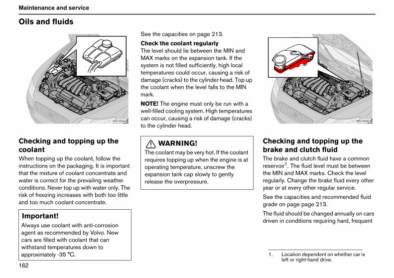
NSO
Maintenance and service
Oi
ChcoWhinstthawatconriskand
ecking and topping up theake and clutch fluide brake and clutch fluid have a commonervoir1. The fluid level must be betweenMIN and MAX marks. Check the levelularly. Change the brake fluid every otherr or at every other regular service.
e the capacities and recommended fluidde on page page 213.
e fluid should be changed annually on carsven in conditions requiring hard, frequent
ImAlagcawiap . Location dependent on whether car is
left or right-hand drive.
ls and fluids
ecking and topping up theolanten topping up the coolant, follow theructions on the packaging. It is importantt the mixture of coolant concentrate ander is correct for the prevailing weatherditions. Never top up with water only. Theof freezing increases with both too littletoo much coolant concentrate.
See the capacities on page 213.
Check the coolant regularlyThe level should lie between the MIN andMAX marks on the expansion tank. If thesystem is not filled sufficiently, high localtemperatures could occur, causing a risk ofdamage (cracks) to the cylinder head. Top upthe coolant when the level falls to the MINmark.
NOTE! The engine must only be run with awell-filled cooling system. High temperaturescan occur, causing a risk of damage (cracks)to the cylinder head.
ChbrThrestheregyea
Segra
Thdri
portant!ways use coolant with anti-corrosionent as recommended by Volvo. Newrs are filled with coolant that canthstand temperatures down toproximately -35 °C.
WARNING!The coolant may be very hot. If the coolantrequires topping up when the engine is atoperating temperature, unscrew theexpansion tank cap slowly to gentlyrelease the overpressure.
1

NSP
Maintenance and service
bratrop
IfthfuThbe
king, such as driving in mountains orical climates with high humidity.
Checking and topping up thepower steering fluidCheck the level at every service. The fluiddoes not require changing. The fluid levelmust be between the MIN and MAX marks.
See the capacities and recommended oilgrade on page 213.
If a fault should arise in the power steeringsystem or if the car is without power and mustbe towed, it can still be steered. However thesteering will be much heavier than normal andit will require more effort to turn the wheel.
WARNING!the brake fluid is under the MIN level ine brake fluid reservoir, do not driverther before topping up the brake fluid.e reason for the loss of brake fluid mustinvestigated.

NSQ
Maintenance and service
W
Ch–
–
–
–
NOlenlon
iper blades
anging the wiper bladesLift up the wiper arm and position thewiper blade at 90 degrees to the wiperarm.Pull the wiper blade off the shaft, straightout to the side.Fit the new wiper blade (1), at 90 degreesto the wiper arm.Position the wiper blade (2) under thecurved metal plate (3) and lower the wiperarm.TE! The wiper blades are differentgths. The blade on the driver’s side isger than the blade on the passenger side.

NSR
Maintenance and service
Ba
BaTheinflustacon
Forcon
•
•
•
The battery containscorrosive acid.
Avoid sparks and nakedflames.
Risk of explosion.
ttery
ttery careservice life and function of the battery isenced by factors such as the number of
rts, discharging, driving style, drivingditions and climatic conditions.
the battery to function satisfactorily,sider the following:
Regularly check that the batteryelectrolyte level is correct (A).Check all cells. Use a screwdriver toremove the caps. Each cell has its ownmaximum level mark.If necessary, top up with distilled water tothe battery’s maximum mark.
NOTE! Never fill above the maximummark (A).
• Tighten the caps properly.NOTE! The life of the battery is shortened if itbecomes discharged repeatedly.
Symbols on the batteryThese symbols displayed on the battery.
Use protective goggles.
Further information in theowner’s manual.
Store the battery out of thereach of children.
Important!Always use distilled or deionised water(battery water).

NSS
Maintenance and service
Ba
ChRe–––
–
––––Fit–––––
–
ttery
anging the batterymoving the battery:Switch off the ignition and remove the key.Unscrew the cover over the battery.Wait at least 5 minutes before touchingany electrical terminals. This allows timefor the information in the car’s electricalsystem to be stored in the controlmodules.Remove the lid and unscrew the front wallof the battery box using a screwdriver.Disconnect the negative battery lead.Release the clamp securing the battery.Disconnect the positive battery lead.Remove the battery.ting the battery:Fit the battery into position.Connect the positive lead.Fit the clamp securing the battery.Connect the negative lead.Refit the front wall of the battery box andthe lid.Refit the cover over the battery.
WARNING!Batteries can generate oxyhydrogen gas,which is highly explosive. A spark, whichcan be generated if you connect the jumpleads incorrectly, is sufficient to make thebattery explode. The battery also containssulphuric acid, which can cause seriousburns. If the acid comes into contact witheyes, skin or clothing, flush with largequantities of water. If acid splashes into theeyes, seek medical advice immediately.

NST
Maintenance and service
Re
GeAll
Thesoutab
••••••
emoving the lamp housing:Remove the ignition key and turn the lightswitch to position 0.Withdraw the lamp housing’s lockingpin (1).Pull the lamp housing to the side and thenforward (2).Unplug the connector.Lift out the lamp housing and place it on asoft surface to avoid scratching the lens.
itting the lamp housing:Plug in the connector.Refit the lamp housing and fit the lockingpin. Check that the pin is correctlyinserted.Check the lighting.
he lamp housing must be plugged in andecured in place before the lighting is turnedn or the ignition key inserted into the ignitionwitch.
ImNfinarda
placing bulbs
neralbulb specifications are given on page 219.
following list contains bulbs and point-rce lamps that are specialised or unsui-le for changing except at a workshop:
General interior lighting in the roof.Reading lamps.Glovebox lighting.Direction indicators in the door mirrors.Approach lighting in the door mirrors.High-level brake light.
Changing front bulbsAll front bulbs (except for fog lamps) arechanged by first removing the lamp housingfrom the engine compartment.
R–
–
–
––
F––
–Tsos
portant!ever touch the bulbs glass with yourgers. Grease and oils from your fingerse vaporised by the heat, coating andmaging the reflector.
WARNING!On cars with Bi-Xenon headlamps, allwork on the lights should be carried out atan authorised Volvo workshop.Bi-Xenon headlamps must be handled withextreme care due to the high-voltage unit.

NSU
Maintenance and service
Re
DipRem
––
––
––
ain beamRemove the entire lamp housing.Left-hand headlamp:Turn the bulb holder anticlockwise.Right-hand headlamp:Turn the bulb holder clockwise.Withdraw the bulb holder and change thebulb.Refit the bulb holder. It can only be fittedin one way.Refit the lamp housing.
placing bulbs
ped beamoving the cover and bulb:
Remove the entire lamp housing.Bend aside the catches and remove thecover.Unplug the connector from the bulb.Release the spring clip that secures thebulb. First, press it to the left to release it,then out and down.Pull out the bulb.Refit the lamp housing.
Fitting a new bulb:
– Fit the new bulb. It can only be fitted inone position.
– Press the spring clip up and then slightlyto the right so that it clicks into place.
– Press the connector back on.– Refit the plastic cover.– Refit the lamp housing.
M––
–
–
–

NSV
Maintenance and service
Po–
––
ide marker lampsTwist the bulb holder anticlockwise andwithdraw it. Change the bulb.Refit the bulb holder. It can only be fittedin one way.
sition/parking lampsPull out the bulb holder with a pair ofpliers. Do not pull out the bulb holder bypulling the electrical cable.Replace the bulb.Press the bulb holder back into place. Itcan only be fitted in one way.
Direction indicators– Twist the bulb holder anticlockwise and
remove it.– To remove the bulb from the bulb holder,
press the bulb in and turn it anticlockwise.– Fit a new bulb and refit the bulb holder
into the lamp housing.
S–
–

NTM
Maintenance and service
Re
Fo–
–
–
–––––
Press the bulb holder back into place andrefit the cover.
placing bulbs
g lampsSwitch off all lights and turn the ignitionkey to position 0.Remove the panel from around the lamphousing.Remove the two Torx screws securing thelamp housing and take out the lamphousing.Unplug the connector from the bulb.Turn the bulb anticlockwise and pull it out.Fit the new bulb and turn it clockwise.Plug in the connector to the bulb.Secure the lamp housing with the screwsand press the panel back into place.
Removing the bulb holderAll bulbs in the rear lamp cluster can bechanged from inside the cargo area.
– Switch off all lights and turn the ignitionkey to position 0.
– Remove the covers from the left/rightpanel to access the bulbs.
– These bulbs are located in separate bulbholders.
– Unplug the connector from the bulbholder.
– Squeeze together the catches andremove the bulb holder.
– Replace the bulb.– Plug in the connector.
–

NTN
Maintenance and service
Bul
Lolig1.2.3.4.5.NOFAIafteautcon
ourtesy lightinghere is courtesy lighting under theashboard on the driver and passengerides.
Insert a screwdriver and gently turn sothat the lens detaches.Remove the blown bulb.Fit a new bulb.Refit the lens.
b holder
cation of the bulbs in the rearht clusterBrake lightPosition/parking lampsDirection indicatorRear fog lamp (one side)Reversing lamp
TE! If the error message "BULBLURE"/"CHECK STOP LAMP" remainsr a faulty lamp has been replaced then an
horised Volvo workshop needs to besulted to rectify the fault.
Number plate lighting– Switch off all lights and turn the ignition
key to position 0.– Remove the screw with a screwdriver.– Carefully detach the entire lamp housing
and withdraw it. Turn the connectoranticlockwise and pull out the bulb.
– Replace the bulb.– Insert the connector and turn clockwise.– Refit the entire lamp housing and screw it
into place.
CTds
–
–––

NTO
Maintenance and service
Re
Ca–
––
itting the mirror glass:
First, press the three lugs at top edge ofmirror glass back into position.Then press the three lower lugs back intoposition.
placing bulbs
rgo areaInsert a screwdriver and gently turn sothat the lamp housing comes loose.Remove the blown bulb.Fit a new bulb.
Vanity mirror lightingRemoving the mirror glass:
– Insert a screwdriver underneath the loweredge, in the centre. Carefully prise up thelug on the edge.
– Insert the screwdriver underneath theedge on the left and right-hand sides (bythe black rubber sections). Carefully prisefree the lower edge of the glass.
– Carefully detach and lift aside the entiremirror glass and cover.
– Remove the blown bulb and replace itwith a new one.
F
–
–
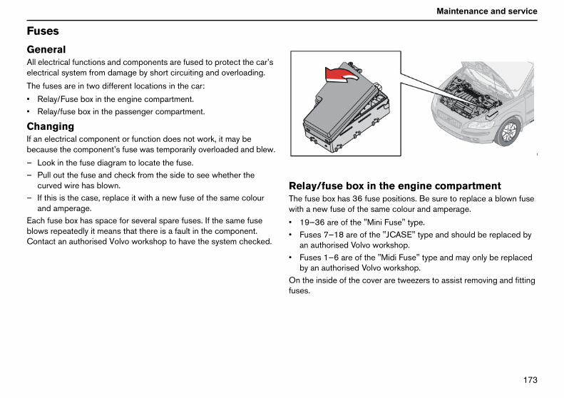
NTP
Maintenance and service
Fu
GeAllele
The
••
ChIf abec
––
–
EacbloCo
he engine compartmentpositions. Be sure to replace a blown fusee colour and amperage.
i Fuse" type."JCASE" type and should be replaced byrkshop.Midi Fuse" type and may only be replacedworkshop.are tweezers to assist removing and fitting
ses
neralelectrical functions and components are fused to protect the car’sctrical system from damage by short circuiting and overloading.
fuses are in two different locations in the car:
Relay/Fuse box in the engine compartment.Relay/fuse box in the passenger compartment.
angingn electrical component or function does not work, it may beause the component’s fuse was temporarily overloaded and blew.
Look in the fuse diagram to locate the fuse.Pull out the fuse and check from the side to see whether thecurved wire has blown.If this is the case, replace it with a new fuse of the same colourand amperage.h fuse box has space for several spare fuses. If the same fuse
ws repeatedly it means that there is a fault in the component.ntact an authorised Volvo workshop to have the system checked.
Relay/fuse box in tThe fuse box has 36 fusewith a new fuse of the sam
• 19—36 are of the "Min• Fuses 7—18 are of the
an authorised Volvo wo• Fuses 1—6 are of the "
by an authorised VolvoOn the inside of the coverfuses.

NTQ
Maintenance and service
Fu
1.2.3.4.5.
6.7.8.9.10.11.12.13.14.15.
system ................................................. 30 A................................................................ 30 Aompartment fuse box ........................ 40 A........................................................................ -................................................................ 15 Aeater, passenger................................................................ 20 A................................................................ 15 A(ECM)/odule (TCM) ....................................... 10 A................................................................ 20 A........................................................................ -................................................................ 15 A................................................................ 10 A
(CCM)MM) ....................................................... 10 A
ses
Radiator fan................................................................................... 50 APower steering.............................................................................. 80 ASupply to passenger compartment fuse box......................... 60 ASupply to passenger compartment fuse box......................... 60 AHeating and ventilation unit,Additional heater relay coil (PTC) (only 4 cyl petrol) ........... 80 AGlow plugs (diesel) ..................................................................... 60 AABS pump..................................................................................... 30 AABS valves .................................................................................... 20 AEngine control module (ECM) .................................................. 30 AVentilation fan................................................................................ 40 AHeadlamp washers...................................................................... 20 ASupply to heated rear window.................................................. 30 AStarter motor relay....................................................................... 30 ATrailer wiring .................................................................................. 40 AReserve .................................................................................................. -
16. Supply to infotainment17. Windscreen wipers .....18. Supply to passenger c19. Reserve ..........................20. Horn ................................21. Fuel-driven additional h
compartment heater....22. SUBWOOFER ............23. Engine control module
Transmission control m24. Diesel filter heater........25. Reserve ..........................26. Ignition switch...............27. A/C compressor...........28. Climate control module
Multimedia module (M

NTR
Maintenance and service
29.30.31.32.
33.
34.
35.
36.
Fog lamp, front.............................................................................. 15 AEngine control module (ECM) .....................................................3 AAlternator voltage regulator ....................................................... 10 AInjectors (5 cyl), oxygen sensor (4 cyl)intercooler (diesel), air preheater valve (diesel) .................... 10 AOxygen sensor heater element (5 cyl),vacuum pump (5 cyl)................................................................... 20 AIgnition coils, injectors (1.6 petrol)fuel pump (diesel)pressure switch, climate control (5 cyl) .................................. 10 AEngine sensor valves, A/C relayoil trap PTC element, injectors (1.8 petrol) ............................ 15 AEngine control module (ECM), accelerator pedalposition sensor ............................................................................. 10 A

NTS
Maintenance and service
Fu
ReTheglo
Ch
–
–
–
––
ses
lay/fuse box in the passenger compartmentfuse box has 50 fuse positions. The fuses are located under the
vebox. The box also provides space for several spare fuses.
anging fuses:
Remove the trim concealing the fuse box by pressing in the pin inthe centre of the clips (1) about 1 cm and then withdrawing theclips.Turn the two wing screws (that secure the fuse box) (2)anticlockwise and remove them.Lower the fuse box (3) half way. Pull it towards the seat until itstops. Lower it completely. The fuse box can be unhooked.Close the fuse box in the reverse order.Remove the pins from the centre of the clips. Fit the trim and theclips. Reinsert the pins to expand the clips and secure the trim.

NTT
Maintenance and service
37.38.39.40.41.42.43.44.45.46.47.48.49.50.
coil (PTC), front lights................................................................... 10 A......................................................................5 A................................................................... 10 Amodule (TCM),) ............................................................... 10 Ale, Keyless control module................. 20 A
trol module.............................................. 10 Aake light switch...................................... 15 Atra lights relay coil ................................ 7.5 A.................................................................. 7.5 Aside) ....................................................... 15 Ager side) ................................................. 15 A................................................................... 20 Aoor............................................................ 20 A......................................................................5 A
Reserve .................................................................................................. -Reserve .................................................................................................. -Reserve .................................................................................................. -Reserve .................................................................................................. -Reserve .................................................................................................. -Reserve .................................................................................................. -Telephone, audio .......................................................................... 15 ASRS system .................................................................................. 10 AElectrical socket, rear seat......................................................... 15 APassenger compartment, glovebox and courtesy lighting.....5 ASunroof relay coil, door mirrors....................................................5 AWasher ........................................................................................... 15 ASRS system .................................................................................. 10 AReserve .................................................................................................. -
51. Auxiliary heater relayparking assistance....
52. ABS system...............53. Power steering ..........54. Transmission control
differential gear (DEM55. Remote control modu56. Battery charging con57. Computer system, br58. Main beam (right), ex59. Main beam, left ..........60. Seat heating (driver’s61. Seat heating (passen62. Sunroof .......................63. Supply to rear right d64. Audio ...........................

NTU
Maintenance and service
Fu
65.66.
67.68.69.70.71.72.73.
74.75.76.77.
78.79.80.81.82.83.84.85.86.
ses
Infotainment system .......................................................................5 AInfotainment control module (ICM),infotainment relay coil10 AReserve .................................................................................................. -Cruise control ..................................................................................5 AClimate control, rain sensor..........................................................5 AReserve .................................................................................................. -Reserve .................................................................................................. -Reserve .................................................................................................. -Sunroof, overhead console (OHC)rear seatbelt reminder....................................................................5 AFuel pump relay ............................................................................ 15 AReserve .................................................................................................. -Reserve .................................................................................................. -Electrical socket in cargo area, accessoryelectronic module (AEM) ........................................................... 15 AReserve .................................................................................................. -Reversing lamp................................................................................5 AReserve .................................................................................................. -Supply to rear left door............................................................... 20 ASupply to front right door........................................................... 25 ASupply to front left door ............................................................. 25 APower passenger seat ................................................................ 25 APower driver’s seat ...................................................................... 25 AInterior lighting relay, power seats ..............................................5 A

NTV
Infotainment systemAudio and telephone 180Control panel 181Audio functions 183
Radio functions 185CD/MD (option) 190CD changer (option) 192
Menu settings and options — Audio 194Telephone (option) 196Telephone functions 198
Menu settings and options — Telephone 204

NUM
Infotainment system
Au
Au(opTheandsysusinstedis
TheSurfeaduc
The
•
•
•
dio and telephone
dio and telephone systemtion)infotainment system integrates the audiotelephone functions. The infotainment
tem can be used easily and convenientlyg the common control panel and the
ering wheel keypad. The control panelplay indicates the present function.
system can be equipped with Dolbyround Pro Logic II (certain markets). Thisture gives more natural sound repro-tion.
re are three levels of audio system:
Performance:AM/FM radio, CD player, 4x20 W, fourfull range loudspeakers (or four full rangespeakers and two tweeters on certainmarkets).High Performance:AM/FM radio, CD player, 4x40 W, eightloudspeakers (woofer and tweeter ineach door).Premium Sound:AM/FM radio, CD player, 4x70 W +25 W, Dolby Pro Logic II, 12 loudspeaker(woofer, mid-range and tweeter in thefront doors, woofer and tweeter in therear doors, woofer and tweeter in thecentre dashboard speaker).
The exact specifications for these levels mayvary between markets. Certain levels are notoffered on all markets. The options list (sub-woofer, CD/MD player, CD changer,telephone, navigation, etc.) differs betweenmarkets. Not all options are available for alllevels.
This owner’s manual describes one way ofoperating the audio and telephone system. Ifyour car has a keypad in the steering wheel,this can also be used.

NUN
Infotainment system
Co
Co
4. Display – Displays options, menus andinformation
5. Slot for inserting/ejecting6. Eject – CD/MD7. Station preset buttons/CD changer disc
(1-6), number/character buttons for thetelephone, and menu presets
isplayhe display shows the function currently inse, for example menu options, messages,lephone numbers or settings. In daylighte information is displayed against a lightackground. In darkness it is displayedgainst a dark background. Clean the displayith a soft, dry cloth. Never use cleaninggent.
his display is also used for the climateontrol system.
enusress MENU to access the main menu. Theettings for the active audio system sourceadio for example) are selected from theain menu. Audio settings cannot be made ife audio system is not switched on.
sing the menu:
Use the navigation button to scroll up anddown in the menu.
ntrol panel
ntrol panel on centre console
Control panel on centre console1. POWER – Audio On/Off2. PHONE – Telephone On/Off/Standby3. VOLUME – Volume control4. CD/MD – Switches between CD and
MD (option)5. AM/FM – Switches between FM1, FM2
and AM6. MENU – Opens the main menu7. ENTER – Selects menu options,
activates a selection or wakes thetelephone from standby.
8. EXIT – Goes back in the menu, cancelsa selection, puts the telephone intostandby, and erases the precedingcharacter when entering text andnumbers.
9. Navigation button – scrolls up/down inthe menus, scans/changes tracks/stations, scroll forward/backward whenentering text and digits, and switchesbetween discs in the CD changer
10. TUNING – Scan/change tracks orstation
11. SOUND – Audio settings (e.g. bass,treble and fader)
12. SCAN – Automatic station search13. AUTO – Finds and stores the strongest
stations
1
111
DTutethbawa
Tc
MPs(rmth
U
–

NUO
Infotainment system
Co
–
–
If thappfearedlow
ntrol panel
Press EXIT to cancel, decline an option,or go back one step in the menustructure.Press ENTER to confirm, select or scrollfrom one submenu to the next submenu.e battery voltage is low, a messageears on the display. The energy saving
ture switches off certain functions oruces the load on the battery, such as byering the volume of the sound system.

NUP
Infotainment system
Au
AuTheposswisysoff,car
SeSeland
•
Thedis
Choose between BASS, TREBLE,FADER, BALANCE, SUBWOOFER(option), CENTRE, and SURROUND.Use the TUNING knob to set the level.The display shows a max-min scale. Themiddle indicates the normal position.
e level for the centre speaker can only beif Dolby Pro Logic II (DPL II ) or 3 channelH) has been selected from the menu. Thewoofer level can only be set if thewoofer is activated.
Audio settingsShown on the
display
ass BASSreble TREBLEalance between
he front and rearpeakers
FADER
alance betweenhe left and right-and speakers
BALANCE
evel forubwoofer
SUBWOOFER(option)
evel for centreoudspeakercertain models)
CENTRE
evel for surroundound (certainodels)
SURROUND
dio functions
dio On/Offignition switch must at least be inition I. Press the POWER button totch the audio system on or off. If the audiotem is active when the ignition is switchedit will reactivate automatically when theis restarted.
lecting the sound sourceect the sound source with the CD/MDAM/FM buttons.
Press the AM/FM button repeatedly toscroll between FM1, FM2 and AM.
selected sound source is shown on theplay.
Volume controlTurn the volume knob clockwise or antic-lockwise to raise or lower the volume. Thevolume can also be controlled using thesteering wheel keypad.
The car has a speed-dependent volumefeature known as active sound control ASC.This adjusts the volume automaticallydepending on the speed of the car.
Pause modeWhen the volume is turned to zero, theCD/MD player switches to pause mode.Reactivate the player by turning up thevolume.
Volume control for TP, PTY,news and alarmsIf a CD is playing when the radio receives atraffic announcement, the CD player enterspause mode. The announcement is played atthe volume selected for that type of message.The system then returns to the volumeselected for the CD player. If the volume isadjusted while the announcement isbroadcast, this new volume is saved andused for the next bulletin.
Audio settings– Press SOUND.– Press the SOUND button repeatedly until
you reach the function you wish to set.
–
Thset(3Csubsub
BTBtsBthLsLl(Lsm

NUQ
Infotainment system
Au
Do(ceDolourea
Thediviamthe
DoMDAMSurhig
Set
––
–
–
–
Thethe3 cbeeOffmo
Use the navigation button or TUNINGknob to set the level.Use the navigation button to select thenext frequency. Five frequencies can beadjusted.Press ENTER to save any changes andexit.Press EXIT to exit without saving anychanges.
dio functions
lby Surround Pro Logic IIrtain models)
lby Surround Pro Logic II, with its centredspeaker in the dashboard, provides morelistic sound reproduction.
normal left and right stereo channels areded into left-centre-right. In addition,bient surround sound is produced throughrear loudspeaker channels.
lby Surround Pro Logic II works in CD andmodes. 3 channel is recommended forand FM radio broadcasts. Dolbyround Pro Logic II is only available for thehest audio level, Premium Sound.
ting the surround sound:
Press MENU.Select the menu for the sound source andpress ENTER.Select AUDIO SETTINGS and pressENTER.Select SURROUND AM/FM orSURROUND CD/MD and press ENTER.Select Dolby Pro Logic II, 3 channel orOff and press ENTER.symbol for Dolby Pro Logic II is shown ondisplay if this has been selected.hannel is shown on the display if this hasn selected.means the system is in normal stereo
de.
Dolby Surround Pro Logic IIand the Dolby icon are trade-marks of Dolby LaboratoriesLicensing Corporation. TheDolby Pro Logic II Surround
System is manufactured under license fromDolby Laboratories Licensing Corporation.
Subwoofer (option)Gives the system a fuller sound and deeperbass:
– Press MENU.– Select the menu for the sound source and
press ENTER.– Select SUBWOOFER and press ENTER.
A check in the box (on the display)indicates that the subwoofer is activated.
Equalizer, front/rear(certain models)Fine adjustment of the sound from the frontspeakers:
– Press MENU.– Select the menu for the sound source and
press ENTER.– Select AUDIO SETTINGS and press
ENTER.– Select Equalizer front (rear) and press
ENTER.
–
–
–
–

NUR
Infotainment system
Ra
Tu–
–
–
MaThema
•
•
Autostoring appears on the display and anumber of strong stations (max. 10) fromthe selected frequency band are stored inthe autostore memory. It there are nostations that are sufficiently strong, Nostation found appears on the display.
he stations are stored on buttons 0-9. Whene radio is in autostore mode, Auto is shownn the display. The text disappears when youturn to the ordinary radio mode. Return toe ordinary radio mode by pressing the AM/M button or EXIT, or by touching (less than.7 seconds) AUTO.
eturning to autostore mode:
To access the most recently storedstations, touch AUTO and then select astation with buttons 0-9.
canningcanning for a station:
Select radio mode with the AM/FMbutton.Press SCAN. Scan appears on thedisplay.Press SCAN or EXIT to quit.
his function automatically searches for theext strong AM or FM station signals. Whene radio finds a station, scanning pauses for
pproximately 8 seconds, after which itontinues.
dio functions
ningSelect radio mode AM, FM1 or FM2 usingthe AM/FM button.Press the left or right arrow on thenavigation button to search for the nextstrong station.Press one of the arrows again to initiate anew search.
nual tuningre are two ways to tune into a station
nually.
Turn the TUNING knob to set the desiredfrequency.Press and hold the left or right arrow onthe navigation button. The frequency rolls
slowly in the selected direction andincreases speed after a few seconds.Release the button when the desiredfrequency appears on the display.
If the frequency needs adjusting, touch oneof the arrows.
Storing stationsTo store stations on the preset buttons 0-9:
– Set the desired station.– Press and hold the button you wish to
store the station on. The sound will bemuted for a couple of seconds andStation stored appear on the display.
You can store up to 10 stations each for AM,FM1 and FM2, i.e. a total of 30 stations.
Autostoring stationsAutomatically tune and store up to ten AM orFM stations in a separate memory. If morethan ten stations are found, the ten strongestare selected. This function is particularlyuseful if you are in an area in which you areunfamiliar with the radio stations and theirfrequencies.
– Select radio mode with the AM/FMbutton.
– Start the search by pressing and holdingAUTO (more than 2 seconds).
–
TthorethF0
R
–
SS
–
–
–Tnthac

NUS
Infotainment system
Ra
RaRDnetto tirreaudbeforRadradthebro
NOor o
PItraPI srecradstroPI sunt
NeMenewsouspebro
dio functions
dio Data System — RDSS is a system that links together specificwork transmitters. It is used, for example,une the correct frequency of a stationspective of the transmitter or the activeio source (e.g. CD). The system can alsoused for receiving traffic information andfinding broadcasts of a specific type.io text is also a component of RDS. A
io station can transmit information aboutradio programme currently beingadcast.
TE! Some radio stations do not use RDSnly use a limited range of its features.
seek (automatic search fornsmitter)eek appears on the display wheneption is poor for the selected station. Theio automatically searches for thengest transmission for that station.eek Exit to cancel is shown on the displayil the station is found.
wsssages with a programme code (such ass from RDS stations) will interrupt othernd sources at the volume set for thiscific feature. As soon as the newsadcast is finished, the audio system
returns to the previous sound source andvolume setting.
Activating News– Select radio mode with the AM/FM
button.– Press MENU.– Select the menu for the sound source and
press ENTER.– Select News and press ENTER.NEWS appears on the display. Press EXIT ifyou do not wish to listen to a news broadcast.The News function remains active and theradio waits for the next news programme.
Deactivating– Select radio mode with the AM/FM
button.– Press MENU.– Select the menu for the sound source and
press ENTER.– Select News and press ENTER.

NUT
Infotainment system
Intcu––
––
––
De–
–
–––
TraTrarupheafeaaudsou
Act–
Select TP from all stations and pressENTER.
searchis function allows you to listen to trafficrmation when travelling between differentas and countries without selecting ation.
Press MENU.Select a sound source.Select Advanced radio settings and pressENTER.Select TP and press ENTER.Select TP search and press ENTER.activatinglect TP search again and press ENTER.
dio textme RDS stations broadcast information,h as about programme content and
ists.playing text information on theplayPress MENU. Select the menu for thesound source and press ENTER (thecurrent sound source is alwayshighlighted when you access the menu ifthe audio system is on).Select Radio text on the menu and pressENTER.activatinglect Radio text again and press ENTER.
erruptions for news from therrent stationSelect the radio with the AM/FM button.Activate the station broadcasting thenews items.Press MENU.Select Advanced audio settings andpress ENTER.Select News station and press ENTER.Select News from current station andpress ENTER.activatingPress MENU. Select the menu for thesound source and press ENTER.Select Advanced radio settings and pressENTER.Select News and press ENTER.Select News station and press ENTER.Select News from all stations and pressENTER.
ffic information — TP stationffic information from RDS stations inter-ts other sound sources. The message isrd at the volume set for this specificture. As soon as the message ends, theio system returns to the previous soundrce and volume setting.
ivating traffic informationPress MENU.
– Select the menu for the sound source.– Select TP and press ENTER.TP is shown on the display when the functionis activated. If the set station does notbroadcast traffic information TP))) appearson the display. Press EXIT if you do not wishto listen to the current traffic announcement.The TP function remains active and the radiowaits for the next traffic announcement.
Activating traffic information from aspecific station– Select radio mode with the AM/FM
button.– Activate the station from which traffic
information is to be received.– Press MENU. Select the menu for the
sound source and press ENTER.– Select Advanced radio settings and press
ENTER.– Select TP and press ENTER.– Select TP Station and press ENTER.– Select TP from current station.Deactivating TP station– Press MENU. Select the menu for the
sound source and press ENTER.– Select Advanced radio settings and press
ENTER.– Select TP and press ENTER.– Select TP Station and press ENTER.
–
TPThinfoaresta
–––
––DeSe
RaSosucartDisdis–
–
DeSe

NUU
Infotainment system
Ra
AlaAlafunshometo wdis
PrUsevar
–
––
NOdes
Pro•••••••••
Press ENTER for one or more of the listedprogramme types. The PTY symbol on thedisplay lights up when the first selectionis made and the radio is set to standbyfor PTY.Press EXIT to go back.Select Search PTY and press ENTER. Ifthe radio finds a station with the selectedprogramme type, this is played.he radio does not find a station with theected programme type, it returns to thevious frequency.
Y mode is then in standby until theected programme type is broadcast.en this happens, the radio automatically
itches to the station broadcasting theected programme type.
activatingSelect Clear all PTY. The PTY symboldisappears from the display and the radioreturns to normal mode.Y standbyset the radio to PTY standby, performps 1-6.
tomatic frequency updatinge AF function is normally activated andures that the radio tunes to the strongestilable transmitter.
dio functions
rmrms are transmitted automatically. Thection cannot be deactivated. ALARM! iswn on the radio display when an alarmssage is broadcast. The function is usedarn motorists of serious accidents or
asters.
ogramme type — PTYthe PTY function to select between the
ious programme types.
Press MENU. Select the menu for thesound source and press ENTER.Select PTY and press ENTER.Select Show PTY and press ENTER. Theset station’s programme PTY will beshown on the display.TE! Not all radio stations have a PTYignation.
gramme type — shown on displayCurrent affairsInformationSportEducationDramaCulturesScienceVaried speechPop music
• Rock music• Easy listening• Light classic• Serious classic• Other music• Weather & Metro• Finance• Children’s progs• Social affairs• Religion• Phone In• Travel & Touring• Leisure & Hobby• Jazz music• Country music• National music• Oldies music• Folk music• Documentary
Searching for a specificprogramme typeSearch through the entire frequency band:
– Select FM 1 or FM 2 and press MENU.– Select the menu for the sound source and
press ENTER.– Select PTY and press ENTER.– Scroll to Select PTY and press ENTER.
–
––
If tselpre
PTselWhswsel
De–
PTToste
AuThensava

NUV
Infotainment system
Au–
–
–Re–
ReTheWhconeve
Act–
–
––De–
EO(EnWitandpro
tomatic frequency updatingPress MENU. Select the menu for thesound source and press ENTER.Select Advanced radio settings and pressENTER.Select AF and press ENTER.activatingSelect AF and press ENTER.
gional radio programmesregional function is normally deactivated.en the function is activated you cantinue to listen to a regional broadcastsn if the signal is weak.
ivating regional radio programmesPress MENU. Select the menu for thesound source and press ENTER.Select Advanced radio settings and pressENTER.Select Regional and press ENTER.REG is shown on the display.activatingSelect REG again and press ENTER.
N - Local/Distant/Offhanced Other Networks)
h EON activated, traffic announcementsnews broadcasts interrupt radio
grammes.
The function has three levels:
• Local - Only interrupts if the signal isstrong.
• Distant - Interrupts even if the signal isweak.
• Off - Deactivated.Activating EON– Press MENU.– Select the menu for the sound source and
press ENTER.– Select Advanced radio settings and press
ENTER.– Select EON and press ENTER.– Select Local, Distant or Off and press
ENTER.
Resetting RDS functionsResets all radio settings to the original factorysettings.
– Press MENU. Select the menu for thesound source and press ENTER.
– Select Advanced radio settings and pressENTER.
– Select Reset all and press ENTER.– Press ENTER again to confirm.

NVM
Infotainment system
CD
St(opActCD
CDIf ththeit hsourup
ChPrebutTheYouste
cancan plays the first ten seconds of eachack.
Press SCAN.Press EXIT to play the current track.
isc textome CDs have title information. The infor-ation is displayed as text on the displaynly applies to the combined CD/MD
layer).
ctivating Disc textPress MENU. Select the menu for thesound source and press ENTER.Select Disc text and press ENTER.
information is stored on the disc, this ishown on the display.
eactivatingSelect Disc text and press ENTER.
/MD (option)
arting the CD/MD playertion)
ivate the CD/MD player by pressing the/MD button. Insert a disc into the player.
se quality of the CD does not comply withrequirements of standard EN60908 or if
as been recorded using poor equipment,nd quality may be poor or playback inter-ted.
anging tracksss the left or right arrow on the navigationton to skip to the previous or next track.track number is shown on the display.can also use the TUNING knob (or
ering wheel keypad).
Fast forward/reversePress and hold the left or right arrow on thenavigation button to search within a track orthe whole disc. Searching continues for aslong as the button is depressed.
RandomThis function chooses a CD track in no parti-cular order.
– Press MENU. Select the menu for thesound source and press ENTER.
– Select Random and press ENTER.RND is shown on the display as long as thefunction is activated.
Deactivating– Select Random again and press ENTER,
or press EXIT.
SStr
––
DSm(op
A–
–Ifs
D–
Important!Use only standard 12 cm CDs, no miniCDs. Do not use CDs with adhesive disclabels. The heat from the CD player maycause the label to detach from the disc.This could damage the CD player.

NVN
Infotainment system
EjePretrafforthepaurea
cting a CD/MDss the eject button to eject the disc. Forfic safety reasons, a CD remains ejectedonly 12 seconds. The player will then feeddisc back into the player and switch tose mode (N/A MD). Press CD/MD toctivate the player.

NVO
Infotainment system
CD
StTh
Sta
––
–Mainse
ast forward/reverseress and hold the left or right arrow on theavigation button to search within a track ore whole disc. Searching continues for asng as the button is depressed.
andomlays tracks from a CD or CDs in randomrder.
Press MENU. Select the menu for thesound source and press ENTER.Select Random and press ENTER.Select Single disc or All discs to playtracks from a single disc or all discs in theCD changer in random order.RND or RND ALL is shown on the displaywhile the function is active.Press the right arrow on the navigationbutton to select the next random track.
eactivatingPress EXIT.
OTE! You can only select the next randomack on the current disc.
cancan plays the first ten seconds of each track.
Press SCAN.OTE! Press EXIT to play the current track.
changer (option)
arting the CD changere CD changer can hold up to six discs.
rting the CD changer:
Press the CD button.Select an empty slot using thebuttons 1-6 (or up/down navigationbutton). The display shows which slotsare empty.Insert a CD into the CD changer.ke sure Insert disc is displayed before yourt the disc
CDsIf the quality of the CD does not comply withthe requirements of standard EN60908 or ifit has been recorded using poor equipment,sound quality may be poor or playback inter-rupted.
Selecting discsSelect the disc you wish to play using thebuttons 1-6 or by pressing the up or downarrow on the navigation button. The numberof the disc and track are shown on thedisplay.
Changing tracksPress the left or right arrow on the navigationbutton to skip to the previous or next track.The track number is shown on the display.You can also use the TUNING knob (orsteering wheel keypad).
FPnthlo
RPo
–
––
–
–
D–Ntr
SS
–N
Important!Use only standard 12 cm CDs, no miniCDs. Do not use CDs with adhesive disclabels. The heat from the CD player maycause the label to detach from the disc.This could damage the CD player.

NVP
Infotainment system
DiSomma
Act–
–If insho
De–
EjePreejethepaupla
EjePrethaTheEje
sc texte CDs have title information. The infor-
tion is displayed as text on the display.
ivating disc textPress MENU. Select the menu for thesound source and press ENTER.Select Disc text and press ENTER.formation is stored on the disc, this iswn on the display.
activatingSelect Disc text and press ENTER.
cting single discss the eject button. The CD remainscted for only 12 seconds. The changer willn feed the disc back in and switch tose mode. Press CD/MD to reactivate the
yer.
cting all discsss and hold the eject button (for longern 2 seconds) to initiate the eject function.entire magazine is emptied, disc by disc.
ct all is shown on the display.

NVQ
Infotainment system
Me
FM1.2.3.
3.
3.3.
4.5.
5.
5.5.5.5.
5.6.
6.
D menu. Random. News (Off1). TP (Off1). Audio settings4.1. Surround AM/FM (certain models)
4.1.1. Dolby Pro Logic II4.1.2. 3 channel4.1.3. Off1
4.2. Surround CD/MD (certain models)4.2.1. Dolby Pro Logic II4.2.2. 3 channel4.2.3. Off
4.3. Subwoofer (On1) (option)4.4. Equalizer front (certain models)4.5. Equalizer rear (certain models)4.6. Automatic volume control
4.6.1. Low4.6.2. Medium4.6.3. High
4.7. Reset all
nu settings and options — Audio
1/FM2 menuNews Off/1
TP On/Off1
PTY1. Select PTY
3.1.1. CLEAR ALL PTY3.1.2. List of PTY
2. Search PTY3. Show PTY On/Off
Radio text On/Off1
Advanced radio settings1. TP
5.1.1. TP station5.1.2. TP search On/Off1
2. News station3. AF On1/Off4. Regional On/Off1
5. EON5.5.1. Off5.5.2. Local5.5.3. Distant1
6. Reset allAudio settings
1. Surround AM/FM (certain models)6.1.1. Dolby Pro Logic II6.1.2. 3 channel6.1.3. Off1
6.2. Surround CD/MD (certain models)6.2.1. Dolby Pro Logic II6.2.2. 3 channel6.2.3. Off
6.3. Subwoofer On1/Off (option)6.4. Equalizer front (certain models)6.5. Equalizer rear (certain models)6.6. Automatic volume control
6.6.1. Low6.6.2. Medium6.6.3. High
6.7. Reset all
AM menu7. Audio settings
7.1. Surround AM/FM (certain models)7.1.1. Dolby Pro Logic II7.1.2. 3 channel Off1
7.2. Surround CD/MD (certain models)7.2.1. Dolby Pro Logic II7.2.2. 3 channel7.2.3. Off
7.3. Subwoofer On1/Off (option)7.4. Equalizer front (certain models)7.5. Equalizer rear (certain models)7.6. Automatic volume control
7.6.1. Low7.6.2. Medium7.6.3. High
7.7. Reset all
C1234

NVR
Infotainment system
CD1.
1.1.1.
2.3.4.5.
5.
5.
5.5.5.5.
5.
1
changer menuRandom
1. Off1
2. Single disc3. All discs
News (Off1)TP (Off1)Disc text (Off1)Audio settings
1. Surround AM/FM (certain models)5.1.1. Dolby Pro Logic II5.1.2. 3 channel5.1.3. Off1
2. Surround CD/MD (certain models)5.2.1. Dolby Pro Logic II1
5.2.2. 3 channel5.2.3. Off
3. Subwoofer (On1) (option)4. Equalizer front (certain models)5. Equalizer rear (certain models)6. Automatic volume control
5.6.1. Low5.6.2. Medium5.6.3. High
7. Reset all
CD/MD menu1. Random2. News (Off1)3. TP (Off1)4. Disc text (Off1)5. Audio settings
5.1. Surround AM/FM (certain models)5.1.1. Dolby Pro Logic II5.1.2. 3 channel5.1.3. Off1
5.2. Surround CD/MD (accessory)5.2.1. Dolby Pro Logic II1
5.2.2. 3 channel5.2.3. Off
5.3. Subwoofer (On1) (option)5.4. Equalizer front (option)5.5. Equalizer rear (option)5.6. Automatic volume control
5.6.1. Low5.6.2. Medium5.6.3. High
5.7. Reset all
. Default/Factory setting

NVS
Infotainment system
Te
Tele
lephone (option)
phone system components

NVT
Infotainment system
1. A
The
2. S
Thebeteleuseinfopan
3. M
Thethe
4. C
Allconpanme
5. P
6. S
Theglo
Ge••
•
ntenna
antenna is mounted on the roof.
teering wheel keypad
majority of the telephone functions cancontrolled using the keypad. When thephone is active, the keypad can only bed for telephone functions. Telephonermation is always displayed on the controlel when the telephone is activated.
icrophone
hands free microphone is integrated inroof console beside the rearview mirror.
ontrol panel
functions (except call volume) can betrolled using the keypad in the controlel. The display shows menu functions,
ssages, telephone numbers, etc.
rivacy handset (option)
IM card
SIM card is located in a holder in thevebox.
neralAlways put traffic safety first.If the driver needs to use the privacyhandset, park the car in a safe place first.Switch off the telephone system whenrefuelling the car.
• Switch off the system near blasting work.• Let only authorised personnel service the
telephone system.
Emergency callsEmergency calls to alarm centres can bemade without a SIM card as long as there iscoverage by a GSM operator.
Making an emergency call:– Activate the telephone.– Ring the emergency number that applies
to your region (within EU: 112).– Press ENTER.
LoudspeakerThe telephone uses the loudspeaker in thedriver’s door or the audio system’s centrespeaker (if there is one).

NVU
Infotainment system
Te
SITheSIMcarCoexpInsetele––
––
–
EI numberblock the telephone, you must provide
ur network operator with the telephone’sEI number. This is a 15 digit serial numberat is programmed in the phone. To displayis number, dial *#06#. Make a note of thismber and keep it in a safe place.
lephone functions
M cardtelephone can only be used with a validcard (Subscriber Identity Module). The
d is provided by your network operator.ntact your network operator if youerience difficulties with the SIM card.rt the SIM card to start using thephone.
Switch off the telephone.Open the glovebox and the cover for theSIM card holder.Pull out the SIM card holder.Place the card metal side up. Ensure thatthe bevelled corner of the SIM cardmatches the bevel of the holder.Carefully press the holder back in.
Double SIM cardsMany network operators offer double SIMcards - one for your car and one for anothertelephone. A double SIM card allows you tohave the same number for two different telep-hones. Ask your network operator about theoffers available and the use of double SIMcards.
Specifications
IMToyoIMththnu
Output 2 W
SIM card Small
Memory entries 2551
1. The capacity of the SIM card’s memoryvaries depending on the subscription.
SMS (Short MessageService)
Yes
Data/Fax No
Dualband Yes (900/1800)

NVV
Infotainment system
Co
teering wheel keypad. ENTER – Accept a call, scroll the menu
or activate the telephone from standby.Press ENTER once to display the lastdialled number.
. EXIT – Terminate/reject a call, scrollback in the menu, cancel a selection orerase entered digits/characters.
. Volume – Increase/decrease call volumeduring a call.
. Navigation button – Scroll up/down inmenus, scroll forward/back whenentering text and digits.
ntrol panel on centre console
1. PHONE – On/Off/Standby.2. MENU – Opens the main menu.3. ENTER – Accept a call, select in the
menu or activate the telephone fromstandby. Press ENTER once to displaythe last dialled number.
4. EXIT – Terminate/reject a call, scrollback in the menu, cancel a selection orerase entered digits/characters.
5. Navigation button – Scroll up or down inthe menus, scroll forwards or back whenentering text and digits.
6. Display.7. Number/character keys and menu
option shortcuts.8. VOLUME – Controls the background
volume from the radio, for example,during a call.
S1
2
3
4

OMM
Infotainment system
Te
SwWhstadiswhwillswithe
Act––Sw–
Sta–
Re–
MaTo
–
Rec
enu shortcutsthe menu system, you can use numbers
stead of the arrows and ENTER to select aenu at the main menu level. Each menu
election is numbered. The numbers arehown on the display together with the menuption.
raffic safetyor safety reasons, parts of the menu systemannot be accessed at speeds in excess ofkm/h. Only activities started in the menu
ystem can be completed. The speed limiteran be deactivated using menunction 5.6.1 Menu lock.
DISntelligent Driver Information System) TheIS system allows incoming telephone calls
nd text (SMS) messages to be delayed soat the driver can concentrate on driving.coming calls and text messages can beelayed by 5 seconds before they areonnected. Missed calls are shown on theisplay. IDIS can be deactivated using menunction 5.6.2.
lephone functions
itchen the telephone system is active or inndby mode, a handset is shown on theplay. If the car’s ignition is switched offile the telephone system is on, the systembe on the next time the ignition istched on. No calls can be received whiletelephone system is switched off.
ivating the telephone systemPress PHONE.Enter the PIN code and press ENTER.itching offPress and hold the PHONE button toswitch off the telephone system.ndby
Press PHONE or EXIT to out thetelephone system into standby.activatingThe system can be reactivated bytouching the PHONE button.
king and receiving callscall:
Dial the number and press ENTER on thesteering wheel keypad or on the controlpanel, or lift the handset.eiving a call:
– Press ENTER or lift the handset. You canalso use Automatic Answer. See menuoption 4.3.
The car’s audio system can be mutedautomatically while a telephone conversationis in progress. See menu option 5.5.3.
Volume reduction duringtelephone callIf the telephone rings when the radio isswitched on, the volume is lowered when thecall is answered. When the call is concluded,the volume returns to the previously set level.It is possible to adjust the radio volume whenthe telephone is in use and this new volumekept after the call is ended. The audio systemcan also be muted during a telephone call.See menu 5.5.3. This function only applies tothe Volvo integrated telephone system.
Ending a callPress EXIT or hang up the handset. Theaudio system resumes its previous activity.Reject an incoming call by pressing EXIT.
StandbyCalls can be received while the audio systemis active and information from an audiosystem source is shown on the display. Thetelephone must be in active mode to use theother functions of the telephone system.
MIninmsso
TFc8scfu
I(IIDathIndcdfu

OMN
Infotainment system
PrMa
–
Thebac
Adjthe
Tocall
–
Search for the desired name or phonenumber in the phone book. Press ENTERto select.To make a call, press and hold thedesired speed dial button for twoseconds or press the button briefly andthen press ENTER.
OTE! When the telephone is switched on, itkes a while before speed dialling is
vailable. Menu option 3.4.1 must bectivated to use the speed dial function.
all waitingtwo-tone signal during a telephone calldicates that there is another incoming call.he display shows: Answer?eceiving a call:
Press ENTER. Your current call will beput on hold.Select Hold/Resume to finish the call andreturn to a call on hold.
o reject the incoming call: Press EXIT.
o end the current call: Press EXIT. Thenction can be de-selected in the menu.
unctions during a calleveral functions are available during a call.
ivacy handset (option)king a call using the handset:
Dial the number using the keypad on thecentre console and lift the handset tomake the call. Press the handset downbefore lifting it.
call is ended when the handset is hungk in its cradle.
ust the handset volume using the dial onside of the handset.
switch to handsfree without ending the:
Press the right arrow on the steeringwheel keypad (or the menu button on thecontrol panel) and select Handsfree.
Press ENTER and return the handset toits cradle. If the handset is alreadyremoved from its cradle at the start of acall, the other party will be audible via thehandsfree system. Press the MENUbutton, scroll to Handset and pressENTER in order to transfer to the handset.
Last dialled numberThe telephone automatically stores the lasttelephone numbers/names called.
Calling the last dialled number:
– Press ENTER on the steering wheelkeypad or control panel (when in activemode).
– Use the navigation buttons to scrollforward or back through the last numbersdialled. These are shown on the display.
– Press ENTER.
Speed dialA number stored in the phone book can belinked to a speed dial button (1-9).
– Select Phone book on the menu andpress ENTER.
– Scroll to Speed dial, menu 3.4, and pressENTER.
– Select which number is to be the speeddial number. Press ENTER to confirm.
–
–
Ntaaa
CAinT
R
–
–
T
Tfu
FS

OMO
Infotainment system
Te
ScrEN
Sevwh
ScrEN
opying entries between the SIM cardnd Phone bookopying from the SIM card to the phoneook:
Press MENU.Select Phone book.Select Copy all.Select From SIM card to phone book andpress ENTER.
ou can also copy entries from the phoneook to the SIM card.
rasing namesrasing from the phone book:
Press MENU.Select Phone book.Select Search.Enter the first letter of the name (or theentire name) and press ENTER.Scroll to the name you wish to delete andpress ENTER.Select Erase to delete the entry.
ntering a name/messageress the button with the relevant character.ress once for the first character, twice fore second character and so on. Press 1 for
pace.
SS
H
Hhe
P
SS
Hhe
Thca
S
P
lephone functions
oll with the navigation button and pressTER to make a selection.
eral functions are available during a callile another call is on hold.
oll with the navigation button and pressTER to make a selection.
Call volumeControl the call volume during the call bypressing the buttons with the large and smallloudspeakers on the steering wheel keypad.
When the telephone is activated, the steeringwheel keypad only controls the telephonefunctions.
The telephone must be in standby mode tocontrol the audio system using the steeringwheel keypad.
Phone bookTelephone numbers and names can bestored in either the telephone memory or theSIM card memory.
If the number of the person calling is stored inthe phone book, the name of the caller will beshown on the display.
The telephone memory can store up to 255names.
Storing a telephone numbers and name:
– Press MENU.– Select Phone book and press ENTER.– Scroll to Enter item and press ENTER.– Enter a name and press ENTER.– Enter a number and press ENTER.– Select the memory in which the entry is to
be saved an d press ENTER.
CaCb
––––
Yb
EE
––––
–
–
EPPths
ecret mode/ecret mode off
Secret mode
old/Resume Choose whether thecall is to be put onhold or resumed
andsfree/adset
Use the handsfreefunction or headset
hone book Show phone book
ecret mode/ecret mode off
Secret mode
andsfree/adset
Use the handsfreefunction or headset
ree-waylling
Conference call(further options)
witch Switch between twocalls
hone book Show phone book
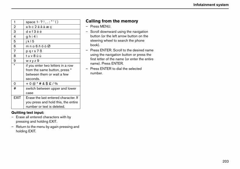
OMP
Infotainment system
Qu–
–
123456789*
0#
EX
itting text input:Erase all entered characters with bypressing and holding EXIT.Return to the menu by again pressing andholding EXIT.
Calling from the memory– Press MENU.– Scroll downward using the navigation
button (or the left arrow button on thesteering wheel to search the phonebook).
– Press ENTER. Scroll to the desired nameusing the navigation button or press thefirst letter of the name (or enter the entirename). Press ENTER.
– Press ENTER to dial the selectednumber.
space 1- ? ! , . : " ' ( )a b c 2 ä å à æ çd e f 3 è ég h i 4 ìj k l 5m n o 6 ñ ö ò Øp q r s 7 ßt u v 8 ü ùw x y z 9if you enter two letters in a rowfrom the same button, press *between them or wait a fewseconds.+ 0 @ * # & $ £ / %switch between upper and lowercase
IT Erase the last entered character. Ifyou press and hold this, the entirenumber or text is deleted.

OMQ
Infotainment system
Me
Te1.
1.1.1.1.
1.
2.2.2.2.
3.3.3.3.
5.2.5. Français FR5.2.6. Italiano5.2.7. Nederlands5.2.8. Português BR5.2.9. Português P5.2.10. Suomi5.2.11. Svenska5.2.12. Dansk5.2.13. Deutsch
5.3. SIM security5.3.1. On5.3.2. Off5.3.3. Automatic
5.4. Change codes5.4.1. PIN code5.4.2. Telephone code
5.5. Volume5.5.1. Ringer volume5.5.2. Ringer tone5.5.3. Mute radio5.5.4. Message beep
5.6. Traffic safety5.6.1. Menu lock5.6.2. IDIS
.7. Factory settings
nu settings and options — Telephone
lephone menuCall log
1. Missed calls2. Received calls3. Outgoing calls4. Erase list
1.4.1. All calls1.4.2. Missed calls1.4.3. Received calls1.4.4. Outgoing calls
5. Call duration1.5.1. Last call1.5.2. Number of calls1.5.3. Total time1.5.4. Reset timeMessages
1. Read2. Write3. Message settings
2.3.1. SMSC number2.3.2. Validity period2.3.3. Message typePhone book
1. Enter item2. Search3. Copy all
3.3.1. SIM to telephone3.3.2. Telephone to SIM
3.4. Speed dial3.4.1. Active3.4.2. Select number
3.5. Empty SIM3.6. Empty telephone3.7. Memory status
4. Call options4.1. Transmit number4.2. Call waiting4.3. Automatic answer4.4. Automatic redial4.5. Call divert
4.5.1. All calls4.5.2. When busy4.5.3. When not answered4.5.4. If unreachable4.5.5. Fax calls4.5.6. Data calls4.5.7. Cancel all diverts
5. Tel. settings5.1. Network selection
5.1.1. Automatic5.1.2. Manual
5.2. Language5.2.1. English UK5.2.2. English US5.2.3. Español5.2.4. Français CAN
5

OMR
Infotainment system
Me1. C1.1Listera
1.2Listera
1.3Listcallboo
1.4Eraand
1.41.41.41.41.5Cal
1.51.51.51.5Thecall
.3. Copy allopy telephone numbers and names frome SIM card to the telephone memory.
.3.1. From SIM to telephone memory
.3.2. From telephone to SIM memory
.4. Speed dialnumber stored in the phone book can be
tored as a speed dial number.
.5. Empty SIMelect to erase the entire memory of the SIMard.
.6. Empty memoryrase the entire telephone memory.
.7. Memory statushows how many entries are occupied byames and numbers in the SIM card andlephone memory. The table shows howany spaces are occupied of the total,.g. 100(250).
. Call options
.1. Transmit numberelect whether or not your own numberhould be displayed to the person you call.ontact your network operator regarding ex-irectory numbers.
nu options, descriptionall log
. Missed callsof missed calls. You can choose to call,
se or store the number in the phone book.
. Received callsof received calls. You can choose to call,
se or store the number in the phone book.
. Outgoing callsof dialled numbers. You can choose to
, erase or store the number in the phonek.
. Erase listse the lists found in the menus 1.1, 1.21.3 as below.
.1. All
.2. Missed
.3. Received
.4. Outgoing
. Call durationl duration of all calls or of the latest call.
.1. Last call
.2. Number of calls
.3. Total time
.4. Reset timetelephone code is required to reset thetimer (see Menu 5.4).
2. Messages2.1. ReadReceived text messages. Select whether toerase, forward, change or save the entiremessage or parts of it.
2.2. WriteWrite a message using the keypad. Choosewhether to save or send it.
2.3. Message settingsEnter the number (SMSC number) of themessage centre to which you want yourmessages transferred as well as how longthey are to be saved at the message centre.
2.3.1. SMSC number2.3.2. Validity period2.3.3. Message typeContact your network operator for infor-mation about these settings and for anSMSC number. Normally, these settingsshould not be altered.
3. Phone book3.1. Enter itemStore names and numbers in the phone book.See the section on phone book functions formore information.
3.2. SearchSearch for a name in the phone book.
3Cth
333As
3Sc
3E
3Snteme
44SsCd

OMS
Infotainment system
Me
4.2Seldurinco
4.3Aut
4.4Cal
4.5Chdive
4.5
4.54.54.54.54.54.5
5. T5.1ChThein t
5.15.15.2Sel
.5.2. Ring tone. There are seven differentring tones.
.5.3. Mute radio: On/Off
.5.4. Message beep
.6. Traffic safetyisengage the speed function, i.e. make allenu options accessible while driving.
.6.1. Menu lock
.6.2. IDIShe IDIS function can be deactivated.coming calls will not be delayed,respective of whether the car is being drivenr not.
.7. Factory settingseset the system’s factory settings.
nu settings and options — Telephone
. Call waitingect whether or not you want to be alerteding a phone call that there is anotherming call.
. Automatic answeromatically answers incoming calls.
. Call backls a previously engaged number.
. Call divert serviceoose when and what type of calls are to berted to a specified telephone number.
.1. All calls (this setting only appliesduring the call in progress)
.2. When busy
.3. When not answered
.4. If unreachable
.5. Fax calls
.6. Data calls
.7. Cancel all diverts
elephone settings. Network selectionoose a network automatically or manually.selected operator is shown in the display
he telephone’s basic mode.
.1. AUTO
.2. Manual
. Languageect the telephone language.
5.2.1. English UK5.2.2. English US5.2.3. Español5.2.4. Français CAN5.2.5. Français FR5.2.6. Italiano5.2.7. Nederlands5.2.8. Português BR5.2.9. Português P5.2.10. Suomi5.2.11. Svenska5.2.12. Dansk5.2.13. Deutsch5.3. SIM securitySelect if the PIN code should be on, off or ifthe telephone should automatically give thePIN code.
5.3.1. On5.3.2. Off5.3.3. Automatic5.4. Change codesChange the PIN code or telephonecode 5.4.1 PIN code 5.4.2.Telephone code(use 1234 until you change to your owncode). The telephone code is used to resetthe call timer. Make a note of your code andsave it in a safe place.
5.5. Volume5.5.1. Volume. Adjust the ring tone
volume.
5
555Dm
55TIniro
5R

OMT
Technical dataType designations 208Dimensions and weights 209Engine specifications 210
Capacities 212Fuel 215Catalytic converter 217
Electrical system 218

OMU
Technical data
Ty
henever contacting your Volvo dealer andhen ordering spare parts and accessories
or your car, it makes things easier if younow your car’s type designation, vehicledentification number and engine number.
. Type designation, VIN, maximumpermitted loads, code number forcolour and trim, and type approvalnumber (on right-hand B-pillar).
. Engine type designation, componentand serial number (on the right-handside of the engine).
. VIN (Type and model year designa-tions and chassis number) stamped inthe engine compartment underneaththe windscreen.
. Gearbox type designation and serialnumber
(a) manual gearbox (on front side)
(b), (c) automatic gearbox (on the top).
pe designations
Wwfki
1
2
3
4

OMV
Technical data
Di
DiLen
Wi
Wh
Fro
Re
WeThetanpastowhitcetcincl(inwe
Trailer with brakes
Maximum trailerweight
Maximumtowball load:
1.6 1200 kg 75 kg1.6D manual 1300 kg1.8 1300 kgothers 1500 kg
Trailer without brakes
Maximum trailerweight
Maximumtowball load:
700 kg 50 kg
WARNING!The car’s driving characteristics changedepending on how heavily it is loaded andhow the load is distributed.
mensions and weights
mensionsgth: 447 cm
dth: 177 cm
eelbase: 264 cm
nt track: 154-155 cm
ar track: 153-154 cm
ightskerb weight includes the driver, the fuel
k 90 % full and all fluids. The weight ofsengers and accessories, such as abar, towball load (when a trailer ished, see table), load carriers, and roof box. influence the payload and must not beuded in the kerb weight. Permitted weightaddition to driver) = Gross vehicleight–Kerb weight.
For the location of the label, see page 208.
1. Max. total weight2. Max. train weight (car+trailer)3. Max. front axle load4. Max. rear axle loadMaximum load: See registration document.
Maximum roof load: 75 kg

ONM
Technical data
En
Engserpag
.4i
E S4O 00( 000T 3( 400NBS
SCSE +/-0.1T
gine specifications
ine type designation, component andial number can be read on the engine, seee 208.
1.6 1.8 2.4 2
ngine designation B4164S3 B4184S11 B5244S5 B5244utput (kW/rps) 74/100 92/100 103/83 125/1
hp/rpm) 100/6000 125/6000 140/5000 170/6orque (Nm/rps) 150/67 165/67 220/67 230/7kpm/rpm) 15.3/4000 16.8/4000 22.4/4000 23.4/4o. of cylinders 4 4 5 5ore (mm) 79 83 83 83troke (mm) 81,4 83.1 90 90
wept volume (dm3 or litres) 1.60 1.80 2.44 2.44
ompression ratio 11.0:1 10.8:1 10.3:1 10.3:1park plugs:lectrode gap (mm) 1.2 1.3 3x0.6 +/-0.1 3x0.6ightening torque (Nm) 15 ±2 12 30 30

ONN
Technical data
.0D
E 4T21
O( 000T 3( 2000NBS
SC 1SET
1
T5 1.6D 2.0D 2
ngine designation B5254T3 D4164T D4204T D420utput (kW/rps) 162/83 81/67 100/67 98/67
hp/rpm) 220/5000 110/4000 136/4000 133/4orque (Nm/rps) 320/25-80 240/ 320/33 320/3kpm/rpm) 32.6/1500-4800 24.5/ 32.6/2000 32.6/o. of cylinders 5 4 4 4ore (mm) 83 75 85 85troke (mm) 93.2 88.3 88 88
wept volume (dm3 or litres) 2.52 1.56 2.00 2.00
ompression ratio 9.0:1 18.3:1 18.5:1 18.5:park plugs:lectrode gap (mm) 0.7 +0.1 - - -ightening torque (Nm) 30 - - -
. France

ONO
Technical data
Ca
En
ExtChcondeahigabnconPetchoextr
Vol
oil grade:2 Viscosity3
1.6 SAE 5W-30
1.8
2.4
2.4
T5
1.6
2.0
2.0
123 .
pacities
gine oil
reme driving conditionseck the oil more often in extreme drivingditions such as alpine driving with a greatl of engine braking or motorway driving at
h speed. These conditions may causeormally high oil temperatures and oilsumption.rol engines: For extreme conditions,ose a fully synthetic engine oil to providea protection.
vo recommends Castrol® oil products.
Engine variantVolume between
MIN – MAXVolume1
litresRecommended
B4164S3 0-0.75 4.0 WSS-M2C913-B
B4184S11 0-0.75 4.3
B5244S5 0-1.6 5.8 ACEA A1/B1
i B5244S4
B5254T3
D D4164T 0-1.0 3.7 WSS-M2C913-B
D D4204T 0-2.0 5.5
D D4204T2
. Including filter change.
. Alternative ACEA A5/B5.
. The oil grade requirement must be fulfilled even if a different viscosity is chosen according to the diagram
Important!Always use oil of the recommendedgrade and correct viscosity.Do not use oil additives. These candamage the engine.
If the system is topped up with a differentoil, contact the nearest authorised Volvoworkshop for servicing.

ONP
Technical data
Ot
ImTh t mix with any other transmission fluid. If thetr rvicing.
Recommended oil gradeG Transmission fluid: WSD-M2C200-C
Transmission fluid: MTF 97309-10
Transmission fluid: JWS 3309C Coolant with corrosion inhibitor mixed with
water, see packaging. The thermostat startsopening at:90 ºC in petrol engines and at 82 ºC indiesel engines.petrol engine (1.6) 82 ºCdiesel engine (1.6D) 83 ºC
A Compressor oil PAGRefrigerant R134a (HFC134a)
B DOT 4+P Power steering fluid: WSS M2C204-A or
equivalent product with same specifica-tions.
her fluids and lubricants
portant!e recommended transmission fluid must be used to prevent damage to the gearbox. Do no
ansmission is topped up with a different fluid, contact an authorised Volvo workshop for se
Fluid Engine variant/number of components Volumeearbox oil 1.6 Manual 5 speed 2.1 litres
1.8 Manual 5 speed 1.9 litres1,6D Manual 5 speed 1.9 litres2.0D Manual 6 speed 1.7 litres2.4 Manual 5 speed 2.1 litres2.4i Manual 5 speed 2.1 litresT5 Manual 6 speed 2.0 litresT5 Automatic gearbox 7.75 litres
oolant 5 cyl. Petrol, manual gearbox 8.0 litres5 cyl. Petrol, automatic gearbox 8.5 litres4 cyl. Petrol (1.8) 7.5 litres4 cyl. Diesel (2.0D) 9.5 litres4 cyl. Petrol (1.6) 6.2 litres4 cyl. Diesel (1.6D) 7.2 litres
ir conditioning1 180-200 grams500-600 grams
rake fluid 0.6 litresower steering System 1.2 litres
of which reservoir 0.2 litres

ONQ
Technical data
Ca
W se a washer antifreeze recommended byolvo mixed with water at temperatureselow freezing.
F
1 information.
Recommended oil grade
pacities
asher fluid 4 cyl. Petrol/Diesel 4.0 litres UVb
5 cyl. Petrol 6.5 litres
uel tank See page 215
. Weights can vary depending on the engine variant. Contact an authorised Volvo workshop for the exact
Fluid Engine variant/number of components Volume

ONR
Technical data
Fu
Co
Emissions of CO2(g/km)
Tank volume(litres)
1 171 551 172 552 199 62
2172 203 62
217T 208 62
224TA
227 58241
1 129 55
2 148 55152145145
2
1
148 55
el
nsumption, emissions and volume
Engine GearboxConsumptionlitre/100 km
.6 B4164S3 Manual 5 speed (IB5) 7.2
.8 B4184S11 Manual 5 speed (MTX75) 7.2
.4 B5244S5 Manual 5 speed (M56) 8.4Automatic gearbox (AW55-50/51) 9.1
.4i B5244S4 Manual 5 speed (M56) 8.5Automatic gearbox (AW55-50/51) 9.1
5 B5254T3 Manual 6 speed (M66) 8.7Automatic gearbox (AW55-50/51) 9.4
5WD
Manual 6 speed (M66) 9.5Automatic gearbox (AW55-50/51) 10.1
.6D D4164T (EURO3)(EURO4)
Manual 5 speed (MTX75) 4.9
.0D D4204T (EURO3) Manual 6 speed (MMT6) 5.6(EURO4) 5.7(EURO3) Manual 5 speed (M56L2) 5.5(EURO4) 5.5
.0D D4204T21 (EURO3)(EURO4) (7CV)
. France
Manual 6 speed (MMT6) 5.6

ONS
Technical data
Fu
FuemOffonwithconequtheis daffehigan
el
el consumption andissions of carbon dioxide
icial fuel consumption figures are baseda standard driving cycle in accordance
EU Directive 80/1268 comb. Fuelsumption figures may change if the car isipped with extra equipment that affectscar’s weight. The manner in which the carriven and other non-technical factors canct fuel consumption. Consumption is
her and power output lower for fuel withoctane rating of 91 RON.
PetrolMost engines can be run with octane ratingsof 91, 95 and 98 RON.
• 91 RON must not be used in 4 cylinderengines.
• 95 RON can be used for normal driving.• 98 RON is recommended for optimum
performance and minimum fuelconsumption.
When driving in temperatures above +38 ºC,it is recommended to use fuel with thehighest possible octane rating for optimumperformance and fuel economy.
Petrol: Standard EN 228
Diesel: Standard EN 590

ONT
Technical data
Ca
CaThepurof eit qcat(cechaplameandbei
talytic converter
talytic converterpurpose of the catalytic converter is to
ify exhaust gases. It is located in the flowxhaust gasses close to the engine so that
uickly reaches operating temperature. Thealytic converter consists of a monolithramic or metal) with channels. Thennel walls are lined with a thin layer oftinum, rhodium and palladium. Thesetals act as catalysts, i.e. they participate in
accelerate a chemical reaction withoutng used up themselves.
Lambda-sondTM oxygen sensorThe Lambda-sond is part of a control systemintended to reduce emissions and improvefuel economy.
An oxygen sensor monitors the oxygencontent of the exhaust gases leaving theengine. This value is fed into an electronicsystem that continuously controls theinjectors. The ratio of air to fuel is continu-ously adjusted. These adjustments createoptimal conditions for efficient combustion,and together with the three-way catalyticconverter reduce harmful emissions (hydro-carbons, carbon monoxide and nitrousoxides).

ONU
Technical data
El
Ge12natchacon
* Caud
** Dsys
If thbatreson
AltMa
StOu
Ba
Vo
Co
Re
1
ectrical system
neralvolt system with a voltage-regulated alter-or. Single pole system in which thessis and engine block are used asductors.
ars equipped with High Performanceio system.
iesel cars with Premium Sound audiotem, fuel-driven heater, RTI.
e battery is changed, replace it with atery of the same cold start capacity anderve capacity as the original (see the decalthe battery).
ernatorx. current = 120/150 A1
arter motortput = 1.4/1.9 kW1
ttery
ltage 12 V 12 V 12 V
ld start capacity (CCA) 520 A 600 A* 700 A**
serve capacity (RC) 100 min 120 min 150 min
. Dependent on engine variant

ONV
Technical data
Bu
1234567li8911G
lbs
Lighting Output W Socket
. Dipped beam 55 H7
. Bi-Xenon 35 D2S
. Main beam 55 HB3
. Brake lights, reversing lamps, rear fog lamp 21 BA15s
. Direction indicators, front/rear (yellow) 21 BAU 15s
. Rear position/parking lamps, rear side marker lamps 5 BAY15d
. Courtesy lighting, cargo area lighting, number plateghting
5 SV8.5
. Vanity mirror 1.2 SV5.5
. Front position/parking lamps, front side marker lamps 5 W 2.1 x 9.5d0. Direction indicators in door mirrors (yellow) 5 W 2.1 x 9.5d1. Fog lamps 55 H11lovebox lighting 3 BA9

OOM
Technical data

OON
AA/CABAddAirAirAirAirAirbAirbAirbinspAlaAlaAlaAll-AlteAppAut
BBacBacBatBirdBonBooBooBraBra
efroster ..........................................................69iesel particle filter ..................................... 102imensions ................................................... 209ipped beam ............................................... 168irection indicators ............................ 47, 169isplay ..............................................................43oor mirrors ....................................................59river’s door control panel ..........................12STC ..................................................... 44, 113
CC ..................................................................67conomical driving ..................................... 100lectrical socket in the centre console .....44lectrical system ......................................... 218missions ..................................................... 215ngine compartment .................................. 158ngine oil ............................................160, 212ngine specifications ................................. 210nvironment ...................................................... 3nvironmental philosophy .............................. 3xpectant mothers .........................................15
an, A/C ...........................................................68an, ECC .........................................................70loor mats ........................................................83luids ............................................................. 213
....................................................................68S ................................................................ 111itional heater ............................................76
conditioning ..............................................66distribution ................................................73distribution, A/C .......................................69quality system, ECC ................................71ag, driver’s side .......................................17ag, passenger side .................................17ags and inflatable curtains,ection ........................................................29
rm .........................................................96, 97rm signals ...................................................97rm system, test .........................................98wheel drive ............................................. 110rnator ...................................................... 218roach lighting ..........................................60
omatic carwashes ................................ 150
krest, front seat .......................................78krests, rear ...............................................84tery ............................100, 119, 165, 218
droppings ............................................. 150net ........................................................... 158ster cushion, integrated ........................33t lid .......................................................... 100
ke fluid ..................................................... 162ke system ............................................... 111
Bulb holder ...................................................170
CCar care .........................................................149Car upholstery ..............................................150Carbon dioxide .............................................216Cargo area ................................. 86, 129, 172Catalytic converter ......................................217Child safety ..................................................... 30Child safety locks .......................................... 95Child seat, fitting ........................................... 35Child seats and airbags ............................... 30Child seats and side airbags ...................... 22Children in the car, placement ................... 32Cigarette lighter ............................................. 44Clean inside and out ........................................3Cleaning, Car washing ...............................150Clutch fluid ....................................................162Cold start ......................................................107Collision sensors ........................................... 24Colour code ..................................................152Combined instrument panel ........................ 38Compass, calibrating .................................... 58Condensation ...............................................159Coolant ..........................................................162Cooling system ............................................100Courtesy lighting .........................................171Crash mode .................................................... 28Cruise control ................................................. 51
DDDDDDDDDD
EEEEEEEEEEEE
FFFFF

OOO
FogFueFueFueFueFus
GGeGeGloGro
HHanHazHeHeHeHeHeHeHeHeHeHo
gnetic zones ..............................................59in beam .................................................... 168intenance ................................................. 155ssages ........................................................43
mber plate lighting ................................ 171
filter .......................................................... 160grade ....................................................... 212
COS ............................................................20int ............................................................... 152intwork damage ...................................... 152nel vents ......................................................66rking .......................................................... 115rking brake ..................................................54rking heater ................................................74rking heater, battery and fuel ..................75rking heater, parking .................................75rking lamps .............................................. 169ssenger compartment filter .....................66trol grade ................................................. 216ch protection, sunroof .............................62lishing ....................................................... 151sition lamps ..................................... 45, 169
lamps ............................................. 45, 170l consumption .............................215, 216l consumption, current ...........................48l filler flap ........................................ 45, 101l system .................................................. 159es ............................................................. 173
arbox, automatic .................................... 107arbox, manual ......................................... 105vebox ..................................................83, 94ss vehicle weight ................................. 209
dbrake .......................................................54ard warning flashers ...............................53
ad restraints ...............................................84adlamp dipper ...........................................47adlamp levelling ........................................45adlamp pattern ....................................... 130adlamp washer ..........................................49adlamps ......................................................45ated front seats .........................................69ated rear window ......................................69ated rearview and door mirrors .............69me safe lighting ........................................60
IIgnition keys ..................................................103Ignition system ............................................... 91Immobiliser ............................................88, 103Indicator symbols .................................. 39, 40Inflatable curtains .......................................... 24Information display ........................................ 43Instrument lighting ......................................... 45Instrument overview, left-hand drive ............8Instrument overview, right-hand drive ....... 10Integrated booster cushion ......................... 33Interior .............................................................. 77Interior lighting ............................................... 80
KKerb weight ..................................................209Key .................................................................... 88Key blade ........................................................ 88Keyless drive .................................................. 91Keys .................................................................. 88Kick-down .....................................................107
LLambda-sond ...............................................217Lighting ..........................................................167Lighting panel ................................................. 45Loading ..........................................................129Locking ............................................................ 93Locks ........................................................ 87, 91Lubricants .....................................................213
MMaMaMaMe
NNu
OOilOil
PPAPaPaPaPaPaPaPaPaPaPaPePinPoPo

OOP
PowPowPun
RRaiReaReaReaRecRecRecRefRefRelRemRemRevRevRimRMRus
SScrSeaSeaSeaSeaSea
railer weight ............................................... 209rip computer .................................................47ype designation ......................................... 208yre pressure ............................................... 135yres, designation of dimensions ............ 132yres, direction of rotation ........................ 136yres, driving characteristics .................... 132yres, speed ratings ................................... 132yres, tread wear indicators ..................... 133
nlocking .........................................................93
anity mirror ................................................. 172ehicle data ................................................. 156iscosity ........................................................ 212
arning symbol, AIRBAG system .............18arning symbols ...................................39, 40arning triangle ......................................... 137asher fluid ................................................. 161ashing the car .......................................... 150axing .......................................................... 151eights ........................................................ 209heel nuts ................................................... 134heels, fitting ............................................. 140hiplash injury ...............................................25
er steering fluid ................................... 163er windows ..............................................55cture repair kit ...................................... 141
n sensor .....................................................50r fog lamp .................................................46rview mirror ..............................................58rview mirror with compass ....................58irculation, A/C .........................................68irculation, ECC ........................................71overy ....................................................... 117rigerant .......................................................66uelling ...................................................... 101ay/fuse box ...................................173, 176
ote control ...............................................88ote control functions .............................88
erse gear inhibitor ................................ 106erse gear inhibitor, five-speed .......... 105s ............................................................... 134E ............................................................... 159tproofing ................................................ 153
atches ..................................................... 152t, power seat ............................................79t, seating position ...................................78tbelt reminder ..........................................15tbelt tensioner .........................................16tbelts ............................................... 14, 151
Service programme ....................................156Side airbags ................................................... 22Side marker lamps ......................................169SIPS bag system ........................................... 23Slippery driving conditions ........................100Spots ..............................................................150SRS system .................................................... 19SRS, switch .................................................... 21Stability system ......................... 44, 113, 114Start assistance ...........................................119Starter motor ................................................218STC ........................................................44, 113Steering lock ................................................103Steering wheel adjustment ......................... 53Stone chips ..................................................152Storage spaces ............................................. 82Sunroof ............................................................ 61Sunscreen, sunroof ....................................... 62Switches in the centre console .................. 44Symbols .........................................................114
TTank volume ..................................................215Temperature selector, ECC ........................ 72Temperature, A/C .......................................... 69Timer, A/C ....................................................... 69Timer, ECC ..................................................... 71Towbar ................................................ 122, 124Towing ...........................................................117Trailer .............................................................120
TTTTTTTTT
UU
VVVV
WWWWWWWWWWW

OOQ
WHWHWinWinWinWip
IPS .............................................................25IPS and child seat/booster cushion ...25dscreen washer ......................................49dscreen wipers .......................................49ter tyres .................................................. 133er blades ............................................... 164

2005
S40VOLVO
20
05
6968TP
OW
NE
R'S
MA
NU
AL
VO
LVO
S4
0
7459 (English). AT 0446. Printed in Sweden, Elanders Infologistics Väst AB, Mölnlycke 2004
TP
74
59