VOLVO Generating set and industrial engines 9 liter (EMS...
76
Users guide and and maintenance manual V V O O L L V V O O G G e e n n e e r r a a t t i i n n g g s s e e t t a a n n d d i i n n d d u u s s t t r r i i a a l l e e n n g g i i n n e e s s 9 9 l l i i t t e e r r ( ( E E M M S S 2 2 ) ) T T A A D D 9 9 4 4 1 1 G G E E 7745269 (11-2005) 33522062701_1_1
Transcript of VOLVO Generating set and industrial engines 9 liter (EMS...

Users guide and and maintenance manual
VVOOLLVVOO
GGeenneerraattiinngg sseett aanndd iinndduussttrriiaall eennggiinneess
99 lliitteerr ((EEMMSS 22))
TTAADD994411GGEE
7745269 (11-2005) 33522062701_1_1

Generating set and industrial engines
9 liter (EMS 2)
OPERATOR’S MANUAL

Safety information ................................................. 2Safety rules for operation and maintenance ......... 3
Introduction ........................................................... 6Environmental responsibility ................................ 6Running in ............................................................ 6Fuel and oils ........................................................ 6Maintenance and spare parts ............................... 6Certified engines .................................................. 7Warranty ............................................................... 7
Introduction ........................................................... 8Technical description ........................................... 8Identification numbers .......................................... 9EMS 2 ............................................................... 10Instrument, EMS 2 ............................................. 11DCU (Display Control Unit) .................................. 12
Starting the engine .............................................. 18Before starting ................................................... 18Starting method EMS 2 ...................................... 19Volvo Penta starter switch .................................. 20Starting in extreme cold ..................................... 21Never use start spray ......................................... 22Starting with auxiliary batteries .......................... 22
Operation ............................................................. 23Checking instruments ........................................ 23Fault indication ................................................... 23Operation at low load ......................................... 23
Stopping the engine ........................................... 24Before stopping .................................................. 24Stop ................................................................... 24After stopping .................................................... 24Extra stop ........................................................... 24
Maintenance schedule ........................................ 25
Maintenance ........................................................ 27Engine, general .................................................. 27Lubrication system .............................................. 30Cooling system .................................................. 33Fuel system ....................................................... 39Electrical system ............................................... 42Component location ............................................ 45
Laying up ............................................................. 46Conservation ...................................................... 46Removing conservation preparations .................. 47
Fault tracing ........................................................ 48Symptoms and possible causes ........................ 48
Diagnostic function ............................................. 49Fault messages ................................................. 49Effect on engine ................................................. 49Operation ........................................................... 50
Fault codes .......................................................... 51
Technical data ..................................................... 64General .............................................................. 64Lubrication system ............................................. 66Fuel system ....................................................... 67Cooling system .................................................. 68Electrical system ............................................... 68
Table of contents
Safety information
Incorrect operation can lead to personal injury and damage to products or property. So read theinstruction book through very carefully before you start the engine or do any maintenance orservicework. If there is still something which is unclear or if you feel unsure about it, please con-tact your Volvo Penta dealer for assistance.
This symbol is used in the instruction book and on the product, to call your attentionto the fact that this is safety information. Always read such information very carefully.
Safety texts in the instruction book have the following order of priority:
WARNING! Warns for the risk of personal injury, major damage to product or property, orserious malfunctions if the instruction is ignored.
IMPORTANT! Is used to call attention to things which could cause damage or malfunctionsto product or property.
NOTE! Is used to call attention to important information, to facilitate work operations or handling.
This symbol is used on our products in some cases and refers to important information inthe instruction book. Make sure that warning and information symbols on the engine are clearlyvisible and legible. Replace symbols which have been damaged or painted over.
Read this chapter very carefully. It has to do with your safety. This describes how safety information is presentedin the instruction book and on the product. It also gives you an introduction to the basic safety rules for using andlooking after the engine.
Check that you have received the correct instruction book before you read on. If not, please contact yourVolvo Penta dealer.

Safety information
3
Safety rules for operation and maintenance
Daily checksMake it a habit to always give the engine and enginebay a visual check before operation (before the en-gine is started) and after driving (when the enginehas been stopped). This helps you to quickly discov-er whether any leakage of fuel, coolant, oil or any oth-er abnormal event has happened, or is about to hap-pen.
Fuel fillingThere is always a risk of fire and explosion during fuelfilling. Smoking is not permissible, and the engineshould be stopped.
Never over-fill the tank. Shut the tank cap securely.
Only use the fuel recommended in the instructionbook. The wrong grade of fuel can cause malfunctionsor stop the engine. In a diesel engine, it can alsocause the injection pump to bind and the engine willover-rev, entailing a strong risk of personal injury andmachinery damage.
Carbon monoxide poisoningOnly start the engine in a well- ventilated area. Whenoperated in a confined space, exhaust fumes andcrankcase gases must be ventilated.
OperationThe engine must not be operated in environmentswhich contain explosive media since none of the elec-trical and mechanical components are explosionproof.
Going close to a running engine is a safety risk. Hair,fingers, loose clothes, or dropped tools can catch onrotating components and cause severe injury.
When engines are supplied without touch guards, allrotating components and hot surfaces must be pro-tected after installation in their application, if neces-sary for personal safety.
Ignition lockIf the instrument panel does not have a key switch,the engine room must be lockable, to prevent unau-thorized persons from starting the engine. Alternative-ly, a lockable main switch can be used.
Care and maintenanceKnowledge
The instruction book contains instructions for doingthe most common service and maintenance tasks in asafe and correct manner. Read them carefully beforestarting work.
Literature for more major tasks is available from yourVolvo Penta dealer.
Never do a job if you are not entirely sure about howto do it. Please contact your Volvo Penta dealer andask for assistance instead.
Stop the engine
Stop the engine before opening or removing the en-gine hatch/hood. Care and maintenance work shouldbe done with the engine stopped unless otherwisespecified.
Prevent the engine from being started by pulling outthe starter key and cutting the current with the batteryisolator. Lock them in the “Off” position. Fix a noticeby the operator’s seat to say that work is in progress.
Working with, or going close to a running engine is asafety risk. Hair, fingers, loose clothes, or droppedtools can catch on rotating components and cause se-vere injury. Volvo Penta recommends that all servicework which requires the engine to be running shouldbe done by an authorized Volvo Penta workshop.

Safety information
4
Lifting the engine
The existing lugs on the engine should be used for lift-ing. Always check that the lifting devices are in goodcondition and that they have the correct capacity forthe lift (engine weight together with auxiliaries, if fit-ted). For safety at work, the engine should be liftedwith an adjustable lifting boom. All chains or cablesshould be parallel to each other and should be assquare as possible to the top of the engine. Pleasenote that auxiliary equipment installed on the enginecould change its center of gravity. Special lifting de-vices may then be needed to obtain the correct bal-ance and safe handling. Never carry out work on anengine that is only suspended in a lifting device.
Before starting
Re-install all guards which have been removed duringservice work, before re-starting the engine. Make surethat there are no tools or other objects left behind onthe engine.
Never start a turbocharged engine without the air filterin place. The rotating compressor turbine in the turbo-charger can cause severe injury. There is also a riskthat foreign bodies could be sucked in and cause ma-chinery damage.
Fire and explosionFuel and lubrication oil
All fuel, most lubricants and many chemicals areflammable. Always read and observe the advice onthe packages.
Work on the fuel system must be done with the en-gine cold. Fuel leakage and spills on hot surfaces orelectrical components can cause fires.
Store oil and fuel soaked rags and other flammablematerial in a fire-proof manner. In certain circumstanc-es, oil soaked rags can self-ignite.
Never smoke when filling fuel, lubrication oil or whenclose to fuel filling stations or the engine bay.
Non-original spare parts
Components in fuel systems and electrical systemson Volvo Penta engines are designed and manufac-tured to minimize the risk of explosions and fire, in ac-cordance with applicable legal requirements.
The use of non-original spare parts can cause an ex-plosion or fire.
Batteries
Batteries contain and give off an explosive gas, espe-cially when charged. This gas is very flammable andhighly explosive.
Smoking, open flames or sparks must never occur inor near to batteries or the battery locker.
Incorrect connection of a battery cable or start cablecan cause a spark which can be sufficient, in its turn,to make the battery explode.
Start spray
Never use start spray or similar preparations to help instarting an engine with air pre-heating (glow plugs /starting heater). They may cause an explosion in theinlet manifold. Danger of personal injury.
Hot surfaces and fluidsA hot engine always offers the risk of burns. Be onyour guard against hot surfaces: the exhaust mani-fold, turbocharger, oil pan, charge air pipe, startingheater, hot coolant and hot lubricating oil in pipes,hoses etc.
Safety rules for operation and maintenance (contd.)

Safety information
5
ChemicalsMost chemicals, such as glycol, rust preventer, con-servation oils, degreasers etc. are hazardous. Alwaysread and observe the advice on the packages.
Some chemicals, such as conservation oils, are flam-mable and alsodangerous to breathe. Ensure goodventilation and use a protective mask for spraying. Al-ways read and observe the advice on the packages.
Store chemicals and other hazardous material out ofthe reach of children. Hand in surplus or used chemi-cals to a recycling station for destruction.
Lubrication systemHot oil can cause burns. Avoid skin contact with hotoil. Make sure that the oil system is de-pressurizedbefore starting work. Never start or run the engine withthe oil filler cap removed, because of the risk of oilspillage.
Cooling systemAvoid opening the coolant filling cap when the engineis hot. Steam or hot coolant can spray out at thesame time as the pressure built up is lost.
If the filler cap, coolant hose etc., still has to beopened or removed when the engine is hot, undo thefiller cap slowly and carefully, to let the pressure outbefore removing the filler cap completely and startingwork. Note that the coolant can still be hot and causescalding.
Fuel systemAlways protect your hands when searching for leaks.Fluids which leak under pressure can force their wayinto body tissue and cause severe injury. There is arisk of blood poisoning (septicemia).
Always cover the alternator if it is located beneath thefuel filters. Fuel spillage can damage the alternator.
Electrical systemCut the current
Before any work is done on the electrical system, theengine must be stopped and the current cut by switch-ing off the main switch(es). External current supply forengine heaters, battery chargers or other auxiliaryequipment connected to the engine must be discon-nected.
Batteries
Batteries contain a highly corrosive electrolyte. Pro-tect your eyes, skin and clothes during charging andother handling of batteries. Always use protective gog-gles and gloves.
If acid comes into contact with your skin, wash atonce with soap and a lot of water. If you get batteryacid in your eyes, flush at once with a lot of cold wa-ter, and get medical assistance at once.
Electric weldingRemove the positive and negative cables from thebatteries. Then disconnect all cables connected to thealternator.
Disconnect both connectors from the engine controlmodule.
Always connect the welder earth clamp to the compo-nent to be welded, and as close as possible to theweld site. The clamp must never be connected to theengine or in such a way that current can pass througha bearing.
When welding is completed: Always connect the al-ternator cables to the alternator and connectors tothe engine control module before the battery cablesare put back.

IntroductionThis instruction book has been prepared to give you the greatest possible benefit from your Volvo Penta industrialengine. It contains the information you need to be able to operate and maintain the engine safely and correctly.Please read the instruction book carefully and learn to handle the engine, controls and other equipment in a safemanner before you start the engine.
Environmental responsibilityAll of us want to live in a clean, healthy environment,where we can breathe clean air, see healthy trees,have clean water in lakes and seas, and be able toenjoy the sunlight without fearing for our health. Unfor-tunately, this is not a matter of course these days, itis something all of us must work for.
As an engine manufacturer, Volvo Penta has particu-lar responsibility and for this reason, environmentalcare is an obvious foundation of our product develop-ment. Volvo Penta has a wide engine program thesedays, where considerable progress has been made inreducing exhaust fumes, fuel consumption, enginenoise etc.
We hope that you will want to preserve these values.Always observe the advice in the instruction bookabout fuel grades, operation and maintenance, toavoid unnecessary environmental impact. Please con-tact your Volvo Penta dealer if you notice any chang-es such as increased fuel consumption or increasedexhaust smoke.
Please remember to always hand in hazardous wastesuch as drained oil, coolant, old batteries etc. for de-struction at an approved recycling facility.
If we all pull together, we can make a valuable contri-bution to the environment together.
Running inThe engine must be “run in” during its first 10hours, as follows:
Use the engine in normal operation. Full load shouldonly be applied for short periods. Never run the enginefor a long period of time at constant speed during thisperiod.
Higher oil consumption is normal during the first 100-200hours of operation. For this reason, check the oil levelmore frequently than normally recommended.
When an opening clutch is installed, this should bechecked more carefully during the first days. Adjust-ment may need to be done to compensate bedding inof the friction plates.
Fuel and oilsOnly use the grades of fuels and oils recommended inthe instruction book (please refer to the “Maintenance”chapter under the fuel and lubrication system head-ings). Other grades of fuel and oils can cause mal-functions, increased fuel consumption and eventuallyeven shorten the life of the engine.
Always change the oil, oil filter and fuel filter at thespecified intervals.
Maintenance and spare partsVolvo Penta engines are designed for maximum reli-ability and long life. They are built to withstand a de-manding environment, but also to have the smallestpossible environmental impact. These qualities are re-tained through regular service and use of Volvo Pentaoriginal spare parts.
Volvo Penta has a world-wide network of authorizeddealers. They are Volvo Penta product specialists,and have the accessories, original spares, test equip-ment and special tools needed for high quality serviceand repair work.
Always observe the maintenance intervals in theinstruction book, and remember to note the en-gine/transmission identification number when youorder service and spare parts.
IMPORTANT! This instruction book describes the engine and equipment sold by Volvo Penta. Variations inappearance and function of the controls and instruments may occur in certain variants. In these cases,please refer to the instruction book for the relevant application.
Certified enginesIf you own an emission certified engine, which isused in an area where exhaust emissions are regu-lated by law, it is important to be aware of the fol-lowing:
Certification means that an engine type has beenchecked and approved by the relevant authority. Theengine manufacturer guarantees that all engines madeof the same type are equivalent to the certified en-gine.
This makes special demands on the care andmaintenance you give your engine, as follows:
• Maintenance and service intervals recommendedby Volvo Penta must be complied with.
• Only Volvo Penta original spares may be used.
• Service to injection pumps, pump settings and in-jectors must always be done by an authorizedVolvo Penta workshop.
• The engine must not be converted or modified, ex-cept for the accessories and service kits whichVolvo Penta has developed for the engine.
• No installation changes to the exhaust pipe andengine air inlet ducts may be done.
• No seals on the engine may be broken by unau-thorized persons.
The general advice in the instruction book about oper-ation, care and maintenance applies.
IMPORTANT! Neglected or poor care/service,and use of non-original spareparts means thatAB Volvo Penta can no longer be responsible forguaranteeing that the engine complies with thecertified version.
Damage, injury and/or costs which arise fromthis will not be compensated by Volvo Penta.
WarrantyYour new Volvo Penta industrial engine is covered by a limited warranty, under the conditions and instruc-tions compiled in the Warranty and Service book.
Please note that AB Volvo Penta’s liability is limited to the specification in the Warranty and Servicebook. Read it carefully, as soon as possible after delivery. This contains important information such asthe warranty card,service intervals, maintenance, which it is the responsibility of the owner to know, check and carry out. Ifthis is not done, AB Volvo Penta may fully or partly refuse to honor its warranty undertakings.
Please contact your Volvo Penta dealer if you have not received a Warranty and Service book, or acustomer copy of the warranty card.
Introduction

IntroductionTAD940GE, TAD941GE, TAD940VE, TAD941VE, TAD942VE, TAD943VE, TAD950VE, TAD951VE andTAD952VE are in-line, direct injected, 6-cylinder industrial diesel engines. TAD950VE, TAD951VE haveTAD952VE have internal EGR (Exhaust Gas Recirculation).
All engines are equipped with electronically controlled fuel management (EMS 2), turbocharger, intercooler, ther-mostatically controlled cooling systems and electronic speed control.
Technical descriptionEngine and engine block
– The engine block and cylinder head are manufac-tured of alloyed cast iron
– Seven bearing induction hardened crankshaft
– Replaceable wet cylinder liners
– Cast aluminum pistons with oil cooling
– Three piston rings, with a “keystone” type top ring
– Induction hardened, overhead, seven bearingcamshaft with .
– Four valves per cylinder
– Replaceable valve seats and valve guides
Fuel system
– Microprocessor based fuel supply control unit(EMS 2)
– Gear driven fuel supply pump
– Centrally located unit injectors with electromag-netically controlled fuel valves
– Spin-on secondary fuel filter and water trap
– IEGR (Internal Exhaust Gas Recirculation)TAD950VE, TAD951VE, TAD952VE
Lubrication system
– Water cooled oil cooler
– Gear driven oil pump
– Two full flow filters and a spin-on bypass filter
Turbocharging system
– Turbocharger
Cooling system
– Radiator with expansion tank
– Air cooled intercooler
– Belt-driven water pump
– Piston thermostat
Electrical system
– 24V electrical system
– Alternator with charge sensor
80 A (110 A and 140 A optional)
– Engine mounted extra stop (AUX STOP)

Introduction
9
Identification numbers
Explanation of engine designation:
E.g. TAD940GE/TAD940VE
T – Turbo
A – Air to air intercooler
D – Diesel engine
9 – Cylinder volume, liter
4 – Generation
0 – Version
G – Generator unit engine
V – Stationary and mobile operation
E – Emission control
Location of engine signs
The sign above shows examples of:
- Engine designation
- Serial number
- Specification number
The sign above shows examples of:
- Engine designation- Engine power, net, (without fan)
- Max. engine speed
- Main software
- Data set 1
- Data set 2
- Product number
Introduction
10
EMS 2EMS 2 (Engine Management System) is an electronic system with CAN communication (Controller Area Network)for diesel engine control. The system has been developed by Volvo Penta and includes fuel control and diagnosticfunction.
Fuel control
The engine fuel requirement is analyzed up to 100times per second. The amount of fuel injected into theengine and the injection advance are fully electronical-ly controlled, via fuel valves and the unit injectors.
This means that the engine always receives the cor-rect volume of fuel in all operating conditions, whichoffers lower fuel consumption, minimal exhaust emis-sions etc.
Diagnostic function
The task of the diagnostic function is to discover andlocalize any malfunctions in the EMS 2 system, toprotect the engine and to ensure operation in theevent of serious malfunction.
If a malfunction is discovered, this is announced bywarning lamps, a flashing diagnostic lamp or in plainlanguage on the instrument panel, depending on theequipment used. If a fault code is obtained as a flash-ing code or in plain language, this is used for guidancein any fault tracing. Fault codes can also be read byVolvo’s VODIA tool at authorized Volvo Penta work-shops.
If there is a serious malfunction, the engine will beshut down altogether, or the control unit will reducethe power delivered (depending on application). Onceagain, a fault code is set for guidance in any faulttracing.
Summary
The system includes sensors, control unit and unit in-jectors. The sensors send input signals to the controlunit, which controls the unit injectors in its turn.
Input signals
The control unit receives input signals about engineoperating conditions etc. from the following compo-nents:
– coolant temperature sensor
– charge pressure / charge temperature sensor
– crankcase pressure sensor
– position sensor, camshaft
– speed sensor, flywheel
– coolant level sensor
– oil level and temperature sensor
– oil pressure sensor
– fuel pressure sensor
– water in fuel indicator
Output signals
The control module uses the input signals to controlthe following components:
– unit injectors
– starter motor
– main relay
– pre-heating relay
Information from the sensors provides exact informa-tion about current operation conditions and allows theprocessor in the control unit to calculate the correctfuel injection volume and timing, check engine statusetc.

Introduction
11
Instrument, EMS 2NOTE! All instruments are accessories.
CIU - Control Interface UnitThe CIU is the “translator” between the EMS 2 controlunit and the customer’s own control panel. The CIUhas two serial communication links, a fast one and aslow one.
The fast one is a so-called CAN link. All data relatedto instruments, indication lamps, connectors and po-tentiometers is controlled by this link.
The slow link manages diagnostic information forflashing codes etc.
DU - Display UnitThe DU is an instrument panel which shows engineworking values graphically on an LCD screen. It con-sists of an computerised unit for permanent installa-tion in a control panel.
The DU is connected between the engine control unitand the CIU or DCU.
Easy Link instrument(only together with a CIU)The following “Easy Link” instruments are available:– Engine speed / hours counter (fault codes are also
displayed on the tachometer display when the di-agnostic button is pressed)
– Coolant temperature
– Oil pressure
– Oil temperature
– Battery voltage
– Alarm panel
– Turbo pressure
Introduction
12
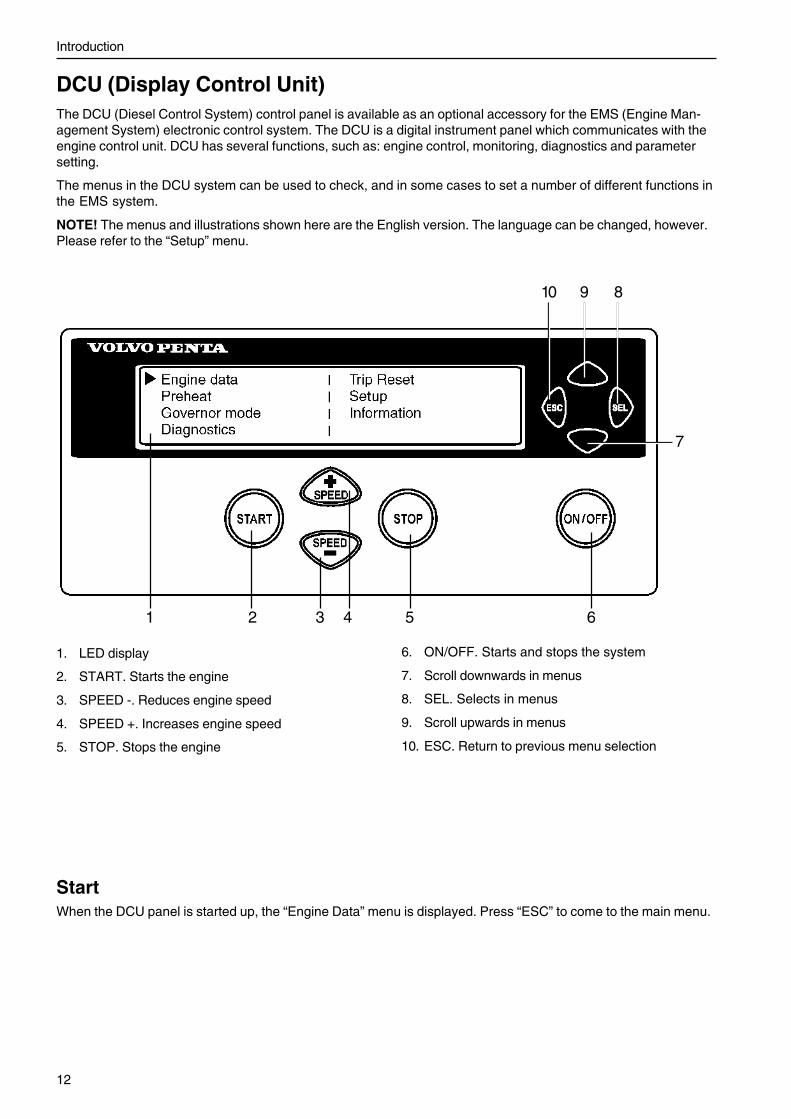
DCU (Display Control Unit)The DCU (Diesel Control System) control panel is available as an optional accessory for the EMS (Engine Man-agement System) electronic control system. The DCU is a digital instrument panel which communicates with theengine control unit. DCU has several functions, such as: engine control, monitoring, diagnostics and parametersetting.
The menus in the DCU system can be used to check, and in some cases to set a number of different functions inthe EMS system.
NOTE! The menus and illustrations shown here are the English version. The language can be changed, however.Please refer to the “Setup” menu.
1. LED display
2. START. Starts the engine
3. SPEED -. Reduces engine speed
4. SPEED +. Increases engine speed
5. STOP. Stops the engine
6. ON/OFF. Starts and stops the system
7. Scroll downwards in menus
8. SEL. Selects in menus
9. Scroll upwards in menus
10. ESC. Return to previous menu selection
StartWhen the DCU panel is started up, the “Engine Data” menu is displayed. Press “ESC” to come to the main menu.
1 2 3 4 5
7
8910
6

Introduction
13
MenusThere are several sub-menus under each main menu.There is not space for all the menu choices on thedisplay. To scroll through the menus, use the “7” and“9” buttons on the display. Press the “SEL” button, no.“8” to make a selection. Please refer to the illustrationon the previous page.
NOTE! The “Setup” menu can be used to select thelanguage that you want to use on the display.
Main menu� Engine data, relevant engine data.
� Preheat, manual activation of pre-heating
� Governor mode, activation of droop.
� Diagnostics, shows fault codes in plain language.
� Trip reset, resets trip data
� Setup, parameter setting
� Information, shows the data for the applicablehardware, software, data set and engine identifica-tion of the engine and DCU
Engine datashows relevant engine data.
• Engine speed, can be controlled with the “SPEED +”and “SPEED –” buttons (rpm)
• Charge pressure (kPa)
• Coolant temperature (°C)
• Charge air temperature (°C)
• Oil pressure (kPa)
• Oil temperature (°C)
• Engine hours (h)
• Battery voltage (V)
• Fuel consumption (l/h)
• Instantaneous fuel consumption (trip fuel) (l)

Introduction
14
Preheatmanual activation of pre-heating. When it is activated,the EMS system senses when started if pre-heating isneeded. For automatic pre-heating, please refer to the“Setup” / “Pre-heat on ignition” menu.
The pre-heating time is adjusted to suit the enginetemperature, and can last for up to 50 seconds bothbefore and after starting. Also refer to “Starting proce-dure, EMS 2”.
• Press “SEL”, the text “Preheat requested” is dis-played.
• The display automatically returns to the “EngineData” menu.
Governor modeactivates/shuts off droop. To set the droop level,please refer to the “Setup” / “Governor gradient” or“Governor droop” menus.
• Select “Isochronous mode” or “Droop mode” withthe SEL button.
Diagnosticsshows the error list containing the 10 latest active andinactive faults. The fault code are shown as text onthe display.
• Scroll through the error list with the arrow keys.
Trip resetresets trip data, such as fuel consumption.
• Press the SEL button to reset trip data.

Introduction
15
Setupparameter setting in the engine’s control systems. Dif-ferent menus appear under “Customer parameter”, de-pending on whether you select “Versatile” or “Genset”from “Set application”.
The parameters that can be set / selected (choice ismade with the SEL button) are:
• Set application, setting of “Versatile” or “Genset”.Different menus appear under “Customer param-eter”, depending on what is chosen here.
• Unit, selection of units of measurement (metric orUS units)
• Language, selection of the language shown in thedisplay. You can choose between English,French, German and Spanish.
• Stop energized to, setting for the external stopinput. Activated at “Stop” or “Run”.“Stop”: The stop input must be connected tovoltage to stop the engine.“Run”: The stop input must be connected to volt-age to run the engine.
• Customer parameter, alarm limit setting. Pleaserefer to “Customer parameter / Versatile” and“Customer parameter / Genset”.
• Throttle input setting, setting of speed controland voltage limits. See “Throttle input setting”.
• Display setting, display setting. See “Display set-ting”.
Customer parameter / Versatile• Idle engine speed - setting idling speed
• Preheat on ignition - activation of automatic pre-heating. The engine control system senses if pre-heating is needed and activates it directly whenswitched on.
• Governor gradient (Nm/rpm) - setting the drooplevel, when this has been activated. Please referto “Governor droop” in the main menu for activa-tion.
• Oil temp warning limit (°C) - setting the alarmlimit for the oil temperature.
• Coolant temp warning limit (°C) - setting thealarm limit for the coolant temperature.

Introduction
16
Customer parameter / Genset• Primary engine speed - selection of engine
speed, 1500 or 1800 rpm.
• Preheat on ignition - activation of automatic pre-heating. The engine control system senses if pre-heating is needed and activates it directly whenswitched on.
• Governor droop (%) - setting the droop level,when this has been activated. Please refer to“Governor droop” in the main menu for activation.
• Overspeed limit (%) - setting the speed for theexcess speed alarm, % of set engine speed.
• Overspeed shutdown - activation of engine shutdown when the excess speed alarm is activated.Please refer to “Overspeed limit” to activate thealarm limit for the excess speed alarm.
• Oil temp warning limit (°C) - setting the alarmlimit for the oil temperature.
• Coolant temp limit (°C) - setting the alarm limitfor the coolant temperature.
Throttle input settingspeed control setting (throttle operation).
• Set throttle mode -“OFF” - engine speed is controlled via the DCUpanel.“ext throttle input” - engine speed is controlled witha potentiometer (accelerator).“ext voltage input” - engine speed is controlled byan external unit.
• Set idle voltage (V) - setting the voltage level atidle.
• Set max voltage (V) - setting the voltage level atmaximum speed.
0
100
Idling MaxVoltage (V)
Potentiometervalue (%)
0
100
Max IdlingVoltage (V)
Potentiometervalue (%)

Introduction
17
Display settingsettings for the display. Adjustment is done with the“7” and “9” buttons, please refer to the DCU panel inthe illustration.
• Set contrast (%) - display contrast adjustment.
• Set backlight time (sec) - sets the time (in sec-onds) for background illumination in the display.The light is then switched off if the panel is notused.
• Set backlight brightness - adjustment of illumi-nation strength in the display.
Informationshows the data for the engine and DCU.
• Engine hardware ID - part number of the enginecontrol module
• Engine software ID - part number of the softwarein the engine control module
• Engine dataset1 ID - part number of engine dataset 1.
• Engine dataset2 ID - part number of engine dataset 2.
• Vehicle ID - chassis number
• DCU hardware ID - part number of the DCU.
• DCU software ID - part number of the software inthe DCU.
• DCU dataset1 ID - part number of DCU data set 1.
• DCU dataset2 ID - part number of DCU data set 2.

18
Starting the engineMake it a habit to give the engine and engine bay a visual check before starting. This will help you to discoverquickly if anything abnormal has happened, or is about to happen. Also check that instruments and warning dis-plays show normal values after you have started the engine.
WARNING! Never use start spray or similar products as a starting aid. Explosion risk!
Before starting• Check that the oil level is between the MAX and
MIN marks. Please refer to the “Maintenance, lu-brication system” chapter:
• Open the fuel taps.
• Check that no leakage of oil, fuel or coolantoccurs.
• Check the air filter pressure drop indicator. Pleaserefer to the “Maintenance, Engine, general” chap-ter:
• Check the coolant level and that the radiator is notblocked externally. Please refer to the “Mainte-nance, cooling system” chapter:
WARNING! Do not open the filler cap (1) whenthe engine is hot. Steam or hot fluid could sprayout.
NOTE! Only open filler cap (1). Do not open filler cap(2).
• Turn the main switch(es) on.
IMPORTANT! Never disconnect the current withthe main switch(es) when the engine is running.This can damage the alternator.
• Move the engine speed control to idle, and releasethe opening clutch/gearbox if installed.
Starting the engine
19
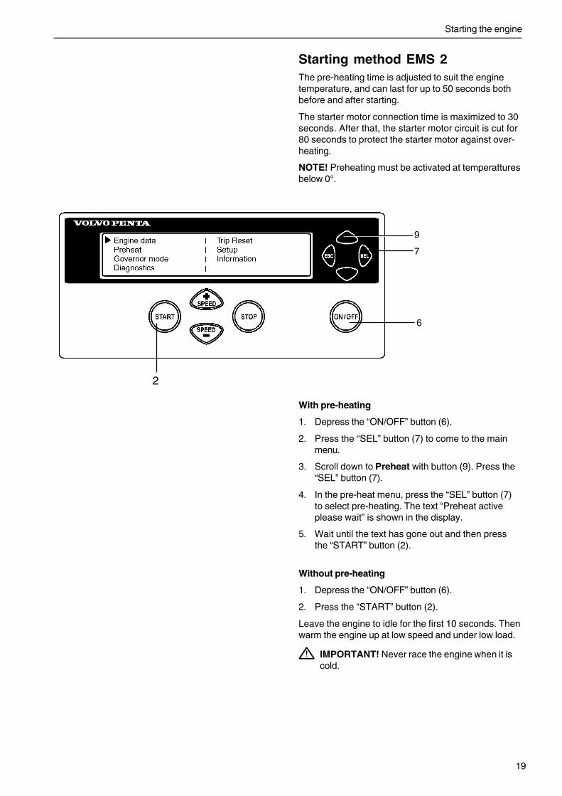
Starting method EMS 2The pre-heating time is adjusted to suit the enginetemperature, and can last for up to 50 seconds bothbefore and after starting.
The starter motor connection time is maximized to 30seconds. After that, the starter motor circuit is cut for80 seconds to protect the starter motor against over-heating.
NOTE! Preheating must be activated at temperatturesbelow 0°.
With pre-heating
1. Depress the “ON/OFF” button (6).
2. Press the “SEL” button (7) to come to the mainmenu.
3. Scroll down to Preheat with button (9). Press the“SEL” button (7).
4. In the pre-heat menu, press the “SEL” button (7)to select pre-heating. The text “Preheat activeplease wait” is shown in the display.
5. Wait until the text has gone out and then pressthe “START” button (2).
Without pre-heating
1. Depress the “ON/OFF” button (6).
2. Press the “START” button (2).
Leave the engine to idle for the first 10 seconds. Thenwarm the engine up at low speed and under low load.
IMPORTANT! Never race the engine when it iscold.
2
6
7
9

Starting the engine
20
Volvo Penta starter switch(standard pre-heating setting)
1. Turn the key to position “I” and checkthe warning lamps
2. Position “II”. Pre-heating is activated (pre-heatingis optional). Wait until the pre-heating indicationlamp goes out. Pre-heating time depends on en-gine temperature.
3. Start the engine in position “III”. Release the keyback to position “I” immediately after the enginehas started.
NOTE! The engine has a built-in starter interlock toprevent involuntary engagement of the starter motorwhen the engine is running. To do a new start attempt,the key must first be turned back to position “O”.
Let the engine run at 500-700 rpm for the first 10 sec-onds. Then warm the engine up at low speed and un-der low load.
IMPORTANT! Never race the engine when it iscold.
Alternative pre-heating:
(set by the supplier)
1. Turn the key to position “I” and check the indica-tion lamps. Pre-heating is activated automatically(pre-heating is optional). Pre-heating time dependson engine temperature.
2. Start the engine in position “III”. Release the keyback to position “I” immediately after the enginehas started.

Starting the engine
21
Starting in extreme coldCertain preparations must be made to facilitate enginestarting, and in some cases to make starting possibleat all.
Use a winter grade fuel (of a well-known make) whichhas been approved for the relevant temperature. Thisreduces the risk of wax deposits in the fuel system.At extremely low temperatures, the use of a fuel heat-er is recommended.
For fully acceptable lubrication, a synthetic engine oilof recommended viscosity for the relevant tempera-ture should be used. Please refer to the “Maintenance,lubrication system” chapter: Synthetic lubricants areable to manage a wider temperature range than miner-al-based lubricants.
Pre-heat the coolant with a separately installed elec-tric engine heater. In extreme cases, a diesel-burningengine heater may be needed. Ask your Volvo Pentadealer for advice.
IMPORTANT! Make sure that the cooling sys-tem is filled with a glycol mixture. Please refer tothe “Maintenance, cooling system” chapter:
The batteries should be in good condition. Cold weath-er reduces battery capacity. Increased battery capaci-ty may be necessary.

Starting the engine
22
Never use start spray
WARNING! Never use start spray or similar prod-ucts as a starting aid. They may cause an explo-sion in the inlet manifold. Personalinjury couldalso be caused.
Starting with auxiliary batteries
WARNING! Batteries (especially auxiliary batter-ies) contain hydrogen which is highly explosivein contact with air. A spark, which can be formedif the auxiliary batteries are wrongly connected,is enough to make a battery explode and causedamage.
1. Check that the auxiliary batteries are connected(series or parallel) so that the rated voltage corre-sponds to the engine system voltage.
2. First connect the red (+) jumper cable to the auxil-iary battery, then to the flat battery. Then connectthe black (–) jumper cable to the auxiliary battery,and lastly to a place which is some distanceaway from the flat batteries, e.g. at the mainswitch on the negative cable or the negative cableterminal on the starter motor.
3. Start the engine.
WARNING! Do not move the connections whenyou attempt to start the engine (risk of arcing),and do not stand and lean over one of the batter-ies.
4. Remove the jumper cables in the reverse orderfrom installation.
WARNING! The ordinary cables to the standardbatteries must not be loosened on any condition.

23
OperationCorrect operation technique is very important for both fuel economy and engine life. Always let the engine warmup to normal operating temperature before operating at full power. Avoid sudden throttle openings and operation athigh engine speeds.
Checking instrumentsCheck all instruments directly after starting, and thenregularly during operation.
IMPORTANT! On engines which operate continu-ously, the lubrication oil level must be checked,at least every 24 hours. Please refer to the“Maintenance, lubrication system” chapter:
Fault indicationIf the EMS 2 system receives abnormal signals fromthe engine, the control unit generates fault codes andalarms, in the form of lamps and audible warnings.This is done by means of CAN signals to the instru-ment.
More information about fault codes and fault tracing isfound in the “Diagnostic function” chapter.
Operation at low loadAvoid long-term operation at idle or at low load, sincethis can lead to increased oil consumption and even-tually to oil leakage from the exhaust manifold, sinceoil will seep past the turbocharger seals and accompa-ny the induction air into the inlet manifold at low turboboost pressure.
One consequence of this is that carbon builds up onvalves, piston crowns, exhaust ports and the exhaustturbine.
At low load, the combustion temperature is so low thatfull combustion of the fuel can not be ensured, whichmeans that the lubrication oil can be diluted by dieselfuel, and the exhaust manifold will eventually leak oil.
If the following points are done as a complementto normal maintenance, there will be no risk ofmalfunctions caused by operation at low load.
• Reduce operation at low load to a minimum. If theengine is regularly test run without load once aweek, operation duration should be limited to 5minutes.
• Run the engine at full load for about 4 hours oncea year. Carbon deposits in the engine and exhaustpipe can then be burned off.
24
Stopping the engineDuring longer breaks in operation, the engine must be warmed up at least once every fortnight. This prevents cor-rosion att acks in the engine. If you expect the engine to be unused for two months or more, it must be laid up:Please refer to the chapter entitled “Laying up”.
IMPORTANT! If there is a risk of frost, the coolant in the cooling system must have sufficient frost protec-tion. Please refer to the “Maintenance, cooling system” chapter: A poorly charged battery can freeze andburst.
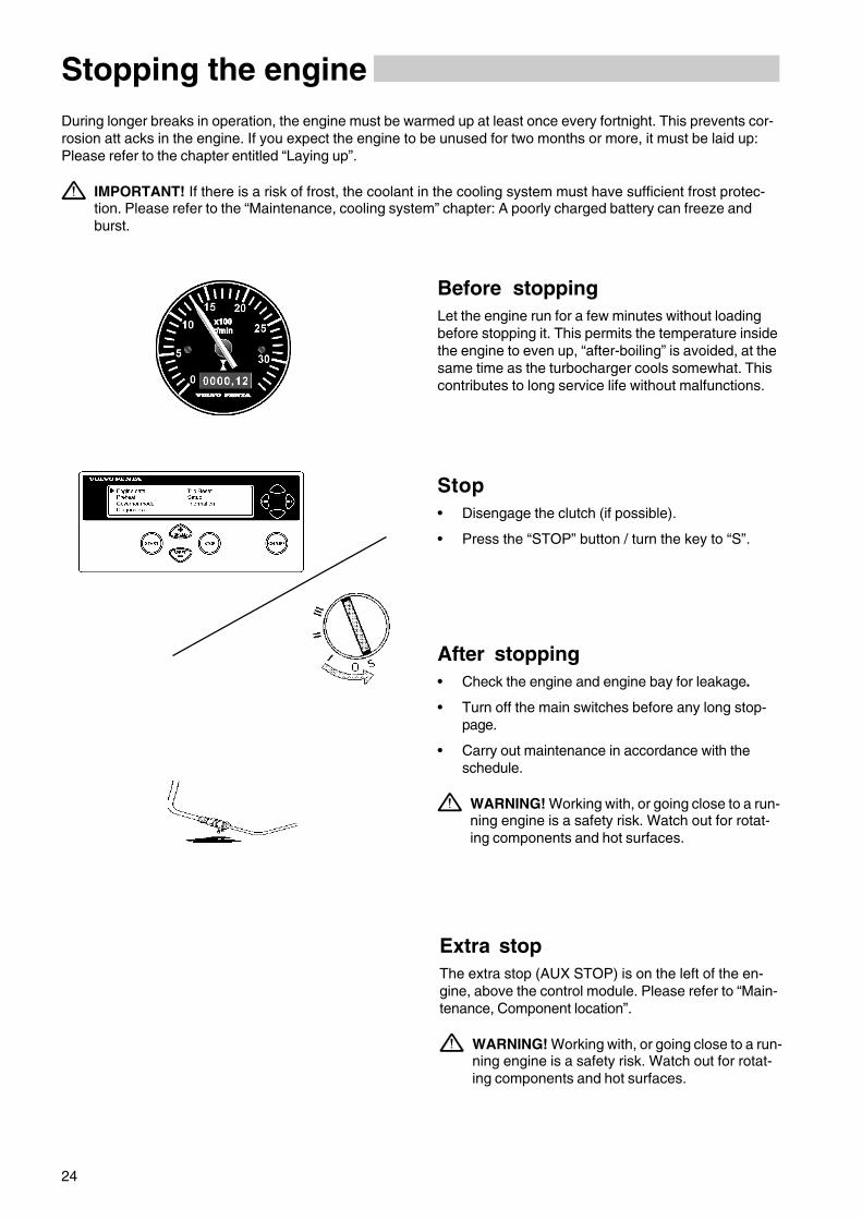
Before stoppingLet the engine run for a few minutes without loadingbefore stopping it. This permits the temperature insidethe engine to even up, “after-boiling” is avoided, at thesame time as the turbocharger cools somewhat. Thiscontributes to long service life without malfunctions.
Stop• Disengage the clutch (if possible).
• Press the “STOP” button / turn the key to “S”.
After stopping• Check the engine and engine bay for leakage.
• Turn off the main switches before any long stop-page.
• Carry out maintenance in accordance with theschedule.
WARNING! Working with, or going close to a run-ning engine is a safety risk. Watch out for rotat-ing components and hot surfaces.
Extra stopThe extra stop (AUX STOP) is on the left of the en-gine, above the control module. Please refer to “Main-tenance, Component location”.
WARNING! Working with, or going close to a run-ning engine is a safety risk. Watch out for rotat-ing components and hot surfaces.

25
Maintenance schedule
MAINTENANCE SCHEDULE
WARNING! Before you start to do any maintenance work, read the “Maintenance”chapter carefully. This contains instructions for doing work in a safe and correct man-ner.
IMPORTANT! When both operation and calendar time are specified, do the mainte-nance job at the interval which is reached first. Maintenance points marked mustbe done by an authorized Volvo Penta workshop.
Daily, before first start
• Engine and engine bay, general inspection ....................................................page 27
• Air filter indicator, inspection 1) .......................................................................page 29
• Oil level, checking and filling ..........................................................................page 31
• Coolant, checking level ..................................................................................page 351) Change the air filter every 24 months.
Every 50 hours / at least every 12 months
• Primary fuel filter. Drain water/contamination .................................................page 41
After the first 150 hours
• Engine oil, changing 1) ....................................................................................page 311) NOTE! An oil change is recommended, change the oil to a grade recommended by Volvo Penta.
After the first 1000 hours
Double rocker arm (iEGR) inspection/adjustment 1)................................................................ not shown
1) Then every 4000 hours. Only TAD950VE, TAD951VE and TAD952VE.
Every 50-600 hours / at least every 12 months
• Engine oil, changing 1) ....................................................................................page 31
• Oil filter/By-pass filter, change 2) ....................................................................page 32
• Primary fuel filter, change ..............................................................................page 40
• Fuel filter, changing ........................................................................................page 401) Oil change intervals vary, depending on oil grade and sulfur content of the fuel. Please refer to page 30.2) Change the filters during each oil change.
GeneralYour Volvo Penta engine and its equipment are designed for high reliability and long life. It is built so as to have min-imal environmental impact. If given preventive maintenance, according to the maintenance schedule, and if VolvoPenta original spares are used, these properties are retained and unnecessary malfunctions can be avoided.

26
Every 400 hours / at least every 12 months
• Fuel tank (sludge trap), drain. ..................................................................... not shown
• Drive belts, inspection ............................................................................... page 28-29
• Batteries, checking the electrolyte level .........................................................page 43
Every 800 hours / at least every 12 months
• Charge air pipe, leakage check. 27
• Primary fuel filter, check ............................................................................ not shown
Every 1000 hours / at least every 6 months
• Coolant filter, changing 1) ................................................................................page 371) Not at same time as coolant change.
Every 2000 hours
Turbocharger, check .................................................................................. not shown
Valve clearance, inspection/adjustment ..................................................... not shown
Every 4000 hours
Double rocker arm (iEGR) inspection/adjustment 2)................................................................ not shown
Every 12 months
EMS 2 system. Inspection with diagnostic tool (VODIA) ...please refer to the “VODIAUser’s Guide”
Engine, general inspection .............................................................................page 27
• Engine, cleaning/painting ........................................................................... not shown
• Inspection, tank ventilation, change. .......................................................... not shown
• Inspection, air compressor, change. .......................................................... not shown
• Air filter inserts, check/change .......................................................................page 29
Every 36 months or every 8000 hours
• Drive belts, change ................................................................................... page 28-29
Every 48 months or every 10000 hours
Cooling system, inspection/cleaning ..............................................................page 35
Coolant, changing ..................................................................................... page 35-36
Newly renovated engine:
After the first 250 hours
Valve clearance, adjustment ...................................................................... not shown
Maintenance schedule

27
Maintenance
This chapter describes how the specified maintenance points should be done. Read them carefully before startingwork. The times when maintenance points need to be attended to are given in the previous chapter: Maintenanceschedule.
WARNING! Read through the safety advice for care and maintenance work in the “Safety information” chap-ter before starting work.
WARNING! Care and maintenance work should be done with the engine stopped unless otherwise specified.Make it impossible to start the engine by removing the ignition key and cutting the system voltage with themain switch. Working with, or going close to a running engine is a safety risk. Watch out for rotating compo-nents and hot surfaces.
Engine, general
General inspectionMake it a habit to give the engine and engine bay a vi-sual check before the engine is started and afteroperation, when the engine has been stopped.This will help you to discover quickly if anything ab-normal has happened, or is about to happen.
Look especially carefully at oil, fuel and coolant leak-age, loose screws, worn or poorly tensioned drivebelts, loose connections, damaged hoses and electri-cal cables. This inspection only takes a few minutesand can prevent serious malfunctions and expensiverepairs.
WARNING! Deposits of fuel, oils and grease onthe engine or in the engine bay are a fire hazardand must be removed as soon as they are dis-covered.
IMPORTANT! If you discover a leakage of oil,fuel or coolant, investigate the cause and fix thefault before you start the engine.
IMPORTANT! Remember the following whenwashing with a high pressure washer: Never aimthe water jet at radiators, intercoolers, seals, rub-ber hoses or electrical components.
Charge air pipe, leakage checkInspect the condition of the charge air hoses, hoseunions and clamp condition for cracks and other dam-age. Change as necessary.
IMPORTANT! Torque the clamps to 9 ±2 Nm(6.5 ±1.4 lbf-ft).
Maintenance
28
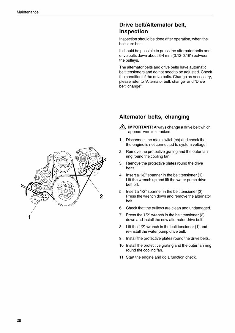
Alternator belts, changing
IMPORTANT! Always change a drive belt whichappears worn or cracked.
1. Disconnect the main switch(es) and check thatthe engine is not connected to system voltage.
2. Remove the protective grating and the outer fanring round the cooling fan.
3. Remove the protective plates round the drivebelts.
4. Insert a 1/2" spanner in the belt tensioner (1).Lift the wrench up and lift the water pump drivebelt off.
5. Insert a 1/2" spanner in the belt tensioner (2).Press the wrench down and remove the alternatorbelt.
6. Check that the pulleys are clean and undamaged.
7. Press the 1/2" wrench in the belt tensioner (2)down and install the new alternator drive belt.
8. Lift the 1/2" wrench in the belt tensioner (1) andre-install the water pump drive belt.
9. Install the protective plates round the drive belts.
10. Install the protective grating and the outer fan ringround the cooling fan.
11. Start the engine and do a function check.
Drive belt/Alternator belt,inspectionInspection should be done after operation, when thebelts are hot.
It should be possible to press the alternator belts anddrive belts down about 3-4 mm (0.12-0.16") betweenthe pulleys.
The alternator belts and drive belts have automaticbelt tensioners and do not need to be adjusted. Checkthe condition of the drive belts. Change as necessary,please refer to “Alternator belt, change” and “Drivebelt, change”.
1
2

29
Maintenance
Drive belt, changing1. Disconnect the main switch(es) and check that
the engine is not connected to system voltage.
2. Remove the protective grating and the outer fanring round the cooling fan.
3. Remove the protective plates round the drivebelts.
4. Insert a 1/2" spanner in the belt tensioner (1).Lift the wrench and remove the drive belt.
5. Thread the drive belt round the fan and remove it.
6. Check that the pulleys are clean and undamaged.
7. Thread the new drive belt over the fan.
8. Lift the 1/2" wrench and install the new drive belt.
9. Install the protective plates round the drive belts.
10. Install the protective grating and the outer fan ringround the cooling fan.
11. Start the engine and do a function check.
Air filter. Check/change.Change the air filters when the indicator remains in thered field after the engine has been stopped. Reinstatethe pressure drop indicator after changing the filter, bypressing in the button.
NOTE! Scrap the old filters. No cleaning or re-use ispermissible.
IMPORTANT! In continuous operation, the filtersshould be checked every 8 hours.When used in extremely dirty environments,such as coal mines, rock crushing mills, youmust use special air filters.
1
Maintenance
30
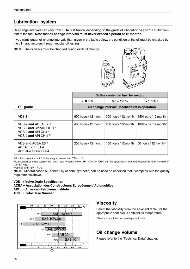
Oil change intervals can vary from 50 to 600 hours, depending on the grade of lubrication oil and the sulfur con-tent of the fuel. Note that oil change intervals must never exceed a period of 12 months.
If you want longer oil change intervals than given in the table below, the condition of the oil must be checked bythe oil manufacturers through regular oil testing.
NOTE! The oil filters must be changed during each oil change.
ViscositySelect the viscosity from the adjacent table, for theappropriate continuous ambient air temperature.
*Refers to synthetic or semi-synthetic oils.
Oil change volumePlease refer to the “Technical Data” chapter.
Lubrication system
*
VDS = Volvo Drain SpecificationACEA = Association des Constructeurs Européenne d’AutomobilesAPI = American Petroleum InstituteTBN = Total Base Number
Sulfur content in fuel, by weight
< 0.5 % 0.5 – 1.0 % > 1.0 %1)
Oil grade Oil change interval: Reached first in operation
VDS-3 600 hours / 12 month 300 hours / 12 month 150 hours / 12 month
VDS-2 and ACEA E7 2) 400 hours / 12 month 200 hours / 12 month 100 hours / 12 month3)
VDS-2 and Global DHD-1 2)
VDS-2 and API CI-4 2)
VDS-2 and API CH-4 2)
VDS and ACEA E3 2) 200 hours / 12 month 100 hours / 12 month 50 hours / 12 month3)
ACEA: E7, E5, E4API: CI-4, CH-4, CG-4
1) If sulfur content is > 1.0 % by weight, use oil with TBN > 15.2) Lubrication oil must comply with both requirements. Note. API: CG-4 or CH-4 can be approved in markets outside Europe (instead of
ACEA A3).3) Use oil with TBN 14-20.NOTE! Mineral based oil, either fully or semi-synthetic, can be used on condition that it complies with the qualityrequirements above.

31
Maintenance
Engine oil, changing
WARNING! Hot oil and hot surfaces can causeburns.
NOTE! Oil changes must be done when the engine iswarm.
1. Connect the drain hose to the oil drain pump andcheck that no leakage can occur.
2. Pump the oil out (or remove the bottom drain plugand drain the engine oil).
NOTE! Collect the old oil and oil filters, and handthem to a re-cycling station for destruction.
3. Remove the drain hose (or install the bottom drainplug).
4. Fill up with engine oil. Change volume, please re-fer to the “Technical Data” chapter.
Oil level, checking and fillingThe oil level must be inside the marked area on thedipstick and must be checked daily beforethe first start.
Top up with oil via the filler opening on the left side ofthe engine.
Check that the correct level has been achieved. Waitfor a few minutes to allow the oil to run down into thesump.
IMPORTANT! Do not fill up above the maximumoillevel. Only use a recommended grade of oil.(please refer to previous page).
NOTE! The oil level sensor only measures the oil lev-el at the time when the ignition is turned on. In otherwords, not continually during operation.
Maintenance
32
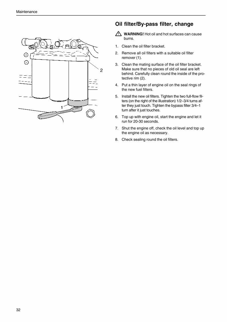
Oil filter/By-pass filter, change
WARNING! Hot oil and hot surfaces can causeburns.
1. Clean the oil filter bracket.
2. Remove all oil filters with a suitable oil filterremover (1).
3. Clean the mating surface of the oil filter bracket.Make sure that no pieces of old oil seal are leftbehind. Carefully clean round the inside of the pro-tective rim (2).
4. Put a thin layer of engine oil on the seal rings ofthe new fuel filters.
5. Install the new oil filters. Tighten the two full-flow fil-ters (on the right of the illustration) 1/2–3/4 turns af-ter they just touch. Tighten the bypass filter 3/4–1turn after it just touches.
6. Top up with engine oil, start the engine and let itrun for 20-30 seconds.
7. Shut the engine off, check the oil level and top upthe engine oil as necessary.
8. Check sealing round the oil filters.
2
33
Maintenance
Cooling system
The cooling system ensures that the engine works at the right temperature. It is a closed system and must there-fore always be filled with a mixture of at least 40% concentrated coolant and 60% water, to offer protection frominterior corrosion, cavitation and frost bursting.
We recommend that you use “Volvo Penta Coolant, Ready Mixed”, or “Volvo Penta Coolant” (concentrated)mixed with pure water acc. to the specification, please refer to “Coolant. Mixing”. This grade of coolant is the onlyone that is developed for and approved by Volvo Penta.
The coolant should contain a good grade of ethylene glycol and a suitable chemical formula for full engine protec-tion. The use of only an anti-corrosion preparation is not permissible for use in Volvo Penta engines. Never usewater by itself as the coolant.
IMPORTANT! Coolant fluid should be used all year round. This also applies in areas where there never isany risk of frost, to give the engine full corrosion protection.Future warranty claims related to engine and accessories may be refused if an unsuitable coolant has beenused, or if the recommendation for coolant mixture has not been observed.
NOTE! The corrosion protection additives become less effective as time passes, which means that the coolantmust be changed. Please refer to the “Maintenance Schedule”. The cooling system should be flushed when thecoolant is changed, please refer to “Cooling system. Flushing”.
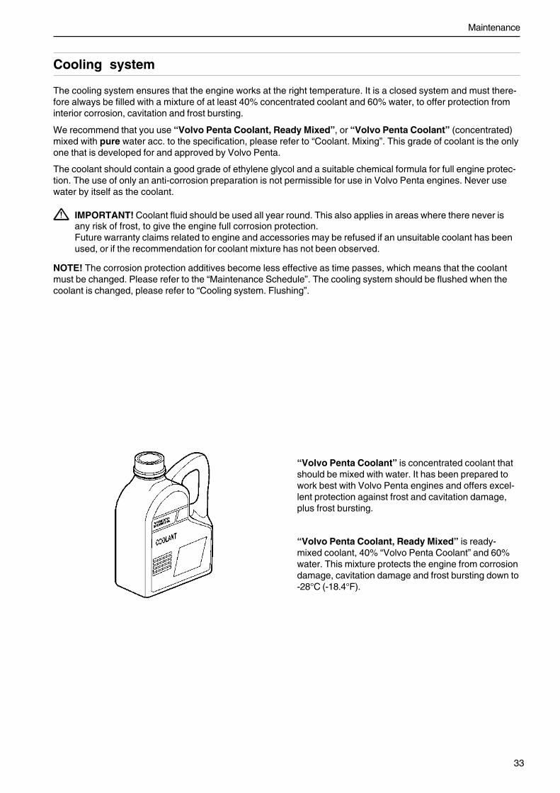
“Volvo Penta Coolant” is concentrated coolant thatshould be mixed with water. It has been prepared towork best with Volvo Penta engines and offers excel-lent protection against frost and cavitation damage,plus frost bursting.
“Volvo Penta Coolant, Ready Mixed” is ready-mixed coolant, 40% “Volvo Penta Coolant” and 60%water. This mixture protects the engine from corrosiondamage, cavitation damage and frost bursting down to-28°C (-18.4°F).
Maintenance
34
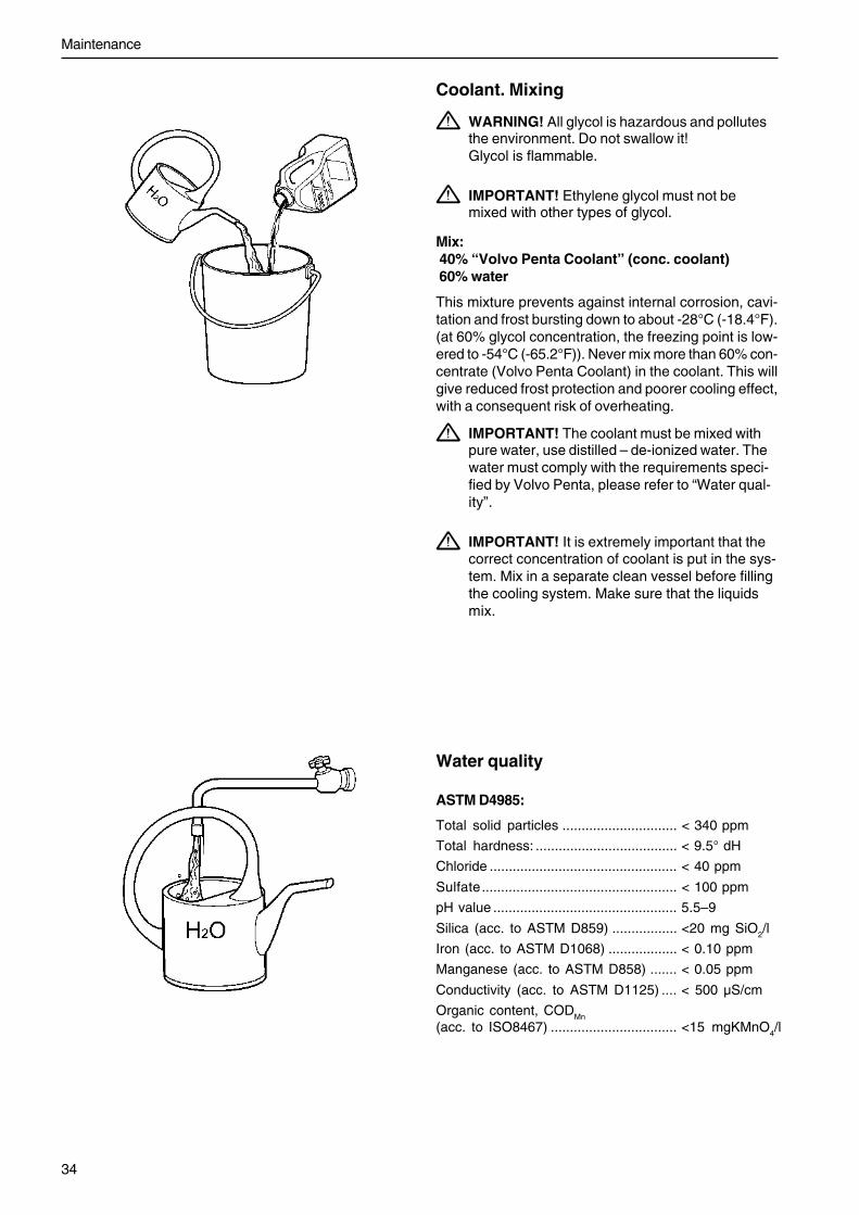
Coolant. Mixing
WARNING! All glycol is hazardous and pollutesthe environment. Do not swallow it!Glycol is flammable.
IMPORTANT! Ethylene glycol must not bemixed with other types of glycol.
Mix: 40% “Volvo Penta Coolant” (conc. coolant) 60% water
This mixture prevents against internal corrosion, cavi-tation and frost bursting down to about -28°C (-18.4°F).(at 60% glycol concentration, the freezing point is low-ered to -54°C (-65.2°F)). Never mix more than 60% con-centrate (Volvo Penta Coolant) in the coolant. This willgive reduced frost protection and poorer cooling effect,with a consequent risk of overheating.
IMPORTANT! The coolant must be mixed withpure water, use distilled – de-ionized water. Thewater must comply with the requirements speci-fied by Volvo Penta, please refer to “Water qual-ity”.
IMPORTANT! It is extremely important that thecorrect concentration of coolant is put in the sys-tem. Mix in a separate clean vessel before fillingthe cooling system. Make sure that the liquidsmix.
Water quality
ASTM D4985:
Total solid particles .............................. < 340 ppm
Total hardness: ..................................... < 9.5° dH
Chloride ................................................. < 40 ppm
Sulfate................................................... < 100 ppm
pH value ................................................ 5.5–9
Silica (acc. to ASTM D859) ................. <20 mg SiO2/l
Iron (acc. to ASTM D1068) .................. < 0.10 ppm
Manganese (acc. to ASTM D858) ....... < 0.05 ppm
Conductivity (acc. to ASTM D1125) .... < 500 µS/cm
Organic content, CODMn
(acc. to ISO8467) ................................. <15 mgKMnO4/l

35
Maintenance
Cooling system, filling
WARNING! Do not open the filler cap (1) when theengine is warm, except in emergencies. Steam orhot fluid could spray out.
NOTE! Do not open filler cap (2).
Filling a completely empty system
1. Open filler cap (1).
2. Check that all drain points are closed.
NOTE! Only use the coolant recommended by VolvoPenta.
3. Mix the correct amount of coolant in advance, toensure that the cooling system is completelyfilled.
4. Fill up with coolant, so that the level ends up be-tween the MIN and MAX markings. Do not startthe engine until the system is vented and com-pletely filled.
Filling should be done with the engine stationary.Fill up slowly, to allow the air to flow out.
5. Start the engine when the cooling system hasbeen completely filled and vented. Open any vent-ing taps some while after starting, to allow shut-inair to escape.
If a heating unit is connected to the engine coolingsystem, the heat control valve should be openedand the installation vented during filling.
6. Stop the engine after about an hour and check thecoolant level. Top up as necessary.
Coolant, inspection
WARNING! Do not open the filler cap (1) whenthe engine is warm, except in emergencies.Steam or hot fluid could spray out.
NOTE! Only open filler cap (1). Do not open filler cap(2).
The coolant level must be higher than the MIN mark-ing. Check the coolant level daily before starting. Topup with coolant as necessary, please refer to Coolant,filling.
Maintenance
36
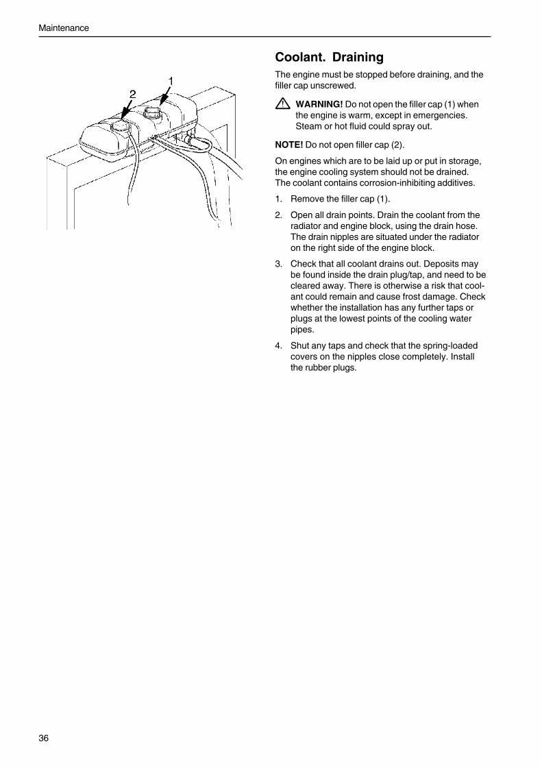
Coolant. DrainingThe engine must be stopped before draining, and thefiller cap unscrewed.
WARNING! Do not open the filler cap (1) whenthe engine is warm, except in emergencies.Steam or hot fluid could spray out.
NOTE! Do not open filler cap (2).
On engines which are to be laid up or put in storage,the engine cooling system should not be drained.The coolant contains corrosion-inhibiting additives.
1. Remove the filler cap (1).
2. Open all drain points. Drain the coolant from theradiator and engine block, using the drain hose.The drain nipples are situated under the radiatoron the right side of the engine block.
3. Check that all coolant drains out. Deposits maybe found inside the drain plug/tap, and need to becleared away. There is otherwise a risk that cool-ant could remain and cause frost damage. Checkwhether the installation has any further taps orplugs at the lowest points of the cooling waterpipes.
4. Shut any taps and check that the spring-loadedcovers on the nipples close completely. Installthe rubber plugs.
37
Maintenance
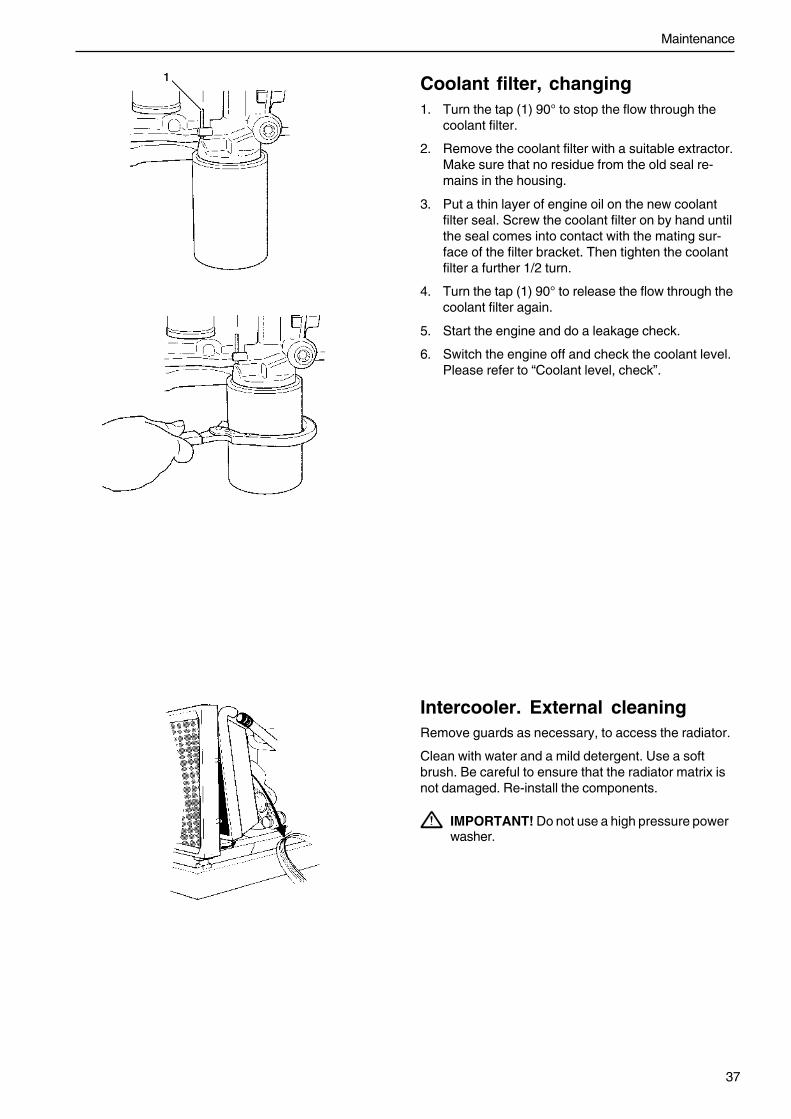
Intercooler. External cleaningRemove guards as necessary, to access the radiator.
Clean with water and a mild detergent. Use a softbrush. Be careful to ensure that the radiator matrix isnot damaged. Re-install the components.
IMPORTANT! Do not use a high pressure powerwasher.
Coolant filter, changing1. Turn the tap (1) 90° to stop the flow through the
coolant filter.
2. Remove the coolant filter with a suitable extractor.Make sure that no residue from the old seal re-mains in the housing.
3. Put a thin layer of engine oil on the new coolantfilter seal. Screw the coolant filter on by hand untilthe seal comes into contact with the mating sur-face of the filter bracket. Then tighten the coolantfilter a further 1/2 turn.
4. Turn the tap (1) 90° to release the flow through thecoolant filter again.
5. Start the engine and do a leakage check.
6. Switch the engine off and check the coolant level.Please refer to “Coolant level, check”.

Maintenance
38
Cooling system, cleaningCooling performance is reduced by deposits in the radi-ator and cooling galleries. The cooling system shouldbe cleaned out when the coolant is changed.
IMPORTANT! Cleaning must not be done if thereis any risk of the cooling system freezing, sincethe cleaning solution does not have any frostprevention ability.
1. Empty the cooling system. Please refer to “Cool-ing system, draining”.
2. Put a hose into the filling hole in the expansiontank and flush with pure water, which complieswith Volvo Penta specifications, please refer tothe “Water Quality” chapter, until the water whichruns out is completely clear.
3. If there should still be some contamination left af-ter flushing for a long time, cleaning can be donewith coolant. Otherwise, continue as in item 8 be-low.
4. Fill the cooling system with 15-20% mixture ofconcentrated coolant. Only use Volvo Penta rec-ommended concentrated coolant, mixed with purewater.
5. Drain the coolant after 1-2 days of operation.
NOTE! To prevent suspended material from settlingback in the system, emptying should be done rapidly,within the space of 10 minutes, when the engine hasnot been standing still for a long time. Remove the fill-er cap and possibly the lower radiator hose to in-crease the speed of emptying.
6. Flush the system at once, very carefully, withpure hot water to stop dirt from settling on the in-ner surfaces again. Flush until the water that runsout is completely clean. Make sure that anyheater controls are set to full heating during emp-tying.
7. If contamination should still be left after a long pe-riod of flushing, you can do a clean-out with VolvoPenta radiator cleaner, followed by finishing-offwith Volvo Penta neutralizer. Carefully follow theinstructions on the package. Otherwise, continueas in item 8 below.
8. When the cooling system is completely free fromcontamination, close the drain taps and plugs.
9. Fill up with Volvo Penta recommended coolant,following the instructions in the chapters entitled“Coolant, mixing” and “Coolant, filling”.
IMPORTANT! It is extremely important that thecorrect concentration and volume of coolant isput in the system. Mix in a separate clean ves-sel before filling the cooling system. Make surethat the liquids mix.

39
Maintenance
Fuel system
Only use the grades of fuel recommended in the fuel specification below. Always observe the greatest cleanlinessduring re-fueling and work on the fuel system.
All work on the injection system of the engine must be done by an authorized workshop.
WARNING! Fire hazard. Work on the fuel system must be done with the engine cold. Fuel spills on hot sur-faces or electrical components can cause fires. Store fuel-soaked rags in a fire-proof manner.
Fuel specificationThe fuel must at least comply with national andinternationalstandards for commercially supplied fuels,such as:
EN590 (with nationally adapted environmental andcoldrequirements)
ASTM D 975 No 1 - D and 2 - D.
JIS KK 2204
Sulfur content: Complying with legal requirements ineach country.content exceeds 0.5 percent by weight,the oil change intervals must be changed. Please re-fer to the “Lubrication system” heading.
Extremely low sulfur content fuel (urban diesel in Swe-den and city diesel in Finland) can cause a loss of upto 5% of power and an increase in fuel consumption ofabout 2–3 %.

Maintenance
40
Fuel filter, changingNOTE! Do not fill the new fuel filter with fuel beforeassembly. There is a risk that contamination could getinto the system and cause malfunctions or damage.
WARNING! The fuel filter must be changed whenthe engine is cold, to avoid the risk of fire due tospilled fuel on hot surfaces.
1. Clean round the fuel filter.
2. Remove the filter with a suitable filter remover.Collect any spilled fuel in a collection vessel.
3. Clean the filter mating surface on the filterbracket.
4. Lubricate the seal with diesel fuel and install thenew fuel filter. Tighten the fuel filter in accordancewith the instructions on the fuel filter.
5. If necessary, vent the fuel system, please refer to“Fuel System, Venting”.
NOTE! If a water trap is installed: change the filter init at the same time as the fuel filter, and clean the wa-ter trap in the plastic bowl under the filter with a softrag.
Primary fuel filter, change1. Undo the cable from the water trap sensor.
2. Remove the water trap filter from the filter bracket.Collect any spilled fuel in a collection vessel.
3. Remove the lower part of the water trap from thefilter.
4. Clean the lower part of the water trap with a softrag. Check that the drain hole in the lower part isnot blocked.
5. Install a new seal on the lower part and lubricatethe seal with diesel fuel. Re-install the lower partof the filter.
6. Lubricate the seal with diesel fuel. Screw the filteronto the filter bracket by hand until the rubber sealjust touches the mating surface. Then tighten afurther half turn, no more.
7. Connect the cable to the water trap sensor.
8. If necessary, vent the fuel system, please refer to“Fuel System, Venting”.
41
Maintenance
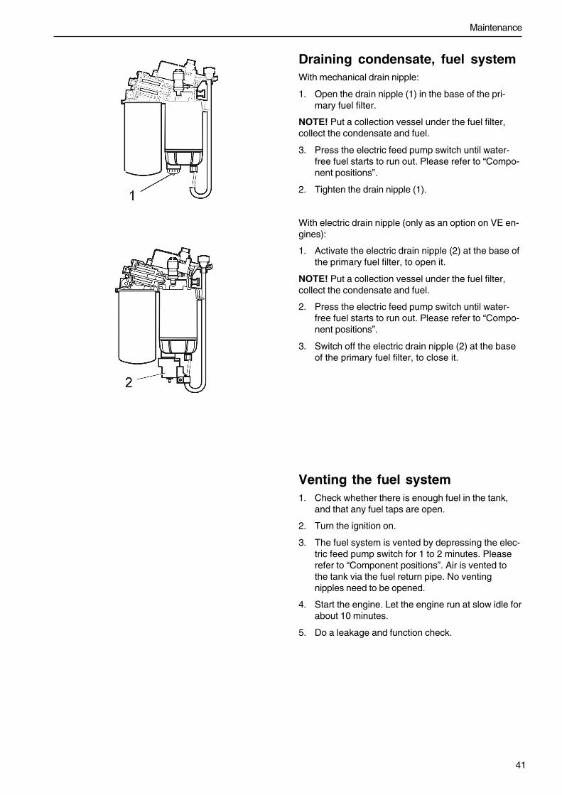
Draining condensate, fuel systemWith mechanical drain nipple:
1. Open the drain nipple (1) in the base of the pri-mary fuel filter.
NOTE! Put a collection vessel under the fuel filter,collect the condensate and fuel.
3. Press the electric feed pump switch until water-free fuel starts to run out. Please refer to “Compo-nent positions”.
2. Tighten the drain nipple (1).
With electric drain nipple (only as an option on VE en-gines):
1. Activate the electric drain nipple (2) at the base ofthe primary fuel filter, to open it.
NOTE! Put a collection vessel under the fuel filter,collect the condensate and fuel.
2. Press the electric feed pump switch until water-free fuel starts to run out. Please refer to “Compo-nent positions”.
3. Switch off the electric drain nipple (2) at the baseof the primary fuel filter, to close it.
Venting the fuel system1. Check whether there is enough fuel in the tank,
and that any fuel taps are open.
2. Turn the ignition on.
3. The fuel system is vented by depressing the elec-tric feed pump switch for 1 to 2 minutes. Pleaserefer to “Component positions”. Air is vented tothe tank via the fuel return pipe. No ventingnipples need to be opened.
4. Start the engine. Let the engine run at slow idle forabout 10 minutes.
5. Do a leakage and function check.
Maintenance
42
Electrical system
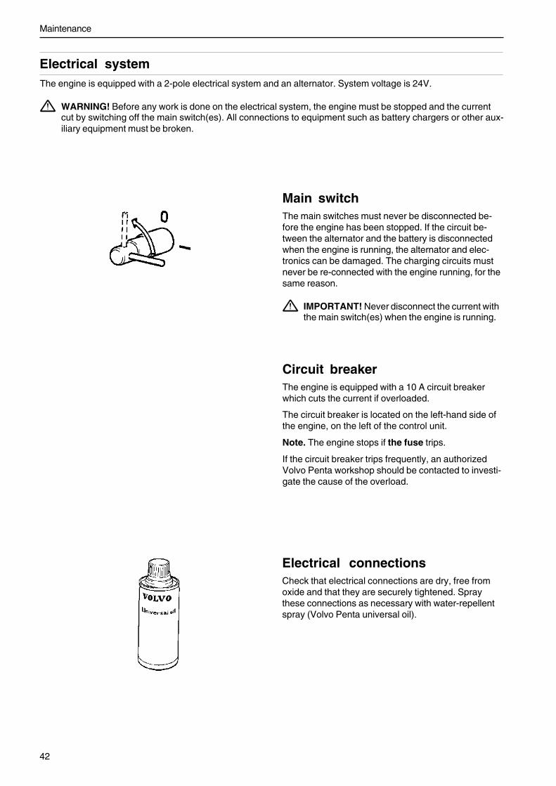
Electrical connectionsCheck that electrical connections are dry, free fromoxide and that they are securely tightened. Spraythese connections as necessary with water-repellentspray (Volvo Penta universal oil).
The engine is equipped with a 2-pole electrical system and an alternator. System voltage is 24V.
WARNING! Before any work is done on the electrical system, the engine must be stopped and the currentcut by switching off the main switch(es). All connections to equipment such as battery chargers or other aux-iliary equipment must be broken.
Main switchThe main switches must never be disconnected be-fore the engine has been stopped. If the circuit be-tween the alternator and the battery is disconnectedwhen the engine is running, the alternator and elec-tronics can be damaged. The charging circuits mustnever be re-connected with the engine running, for thesame reason.
IMPORTANT! Never disconnect the current withthe main switch(es) when the engine is running.
Circuit breakerThe engine is equipped with a 10 A circuit breakerwhich cuts the current if overloaded.
The circuit breaker is located on the left-hand side ofthe engine, on the left of the control unit.
Note. The engine stops if the fuse trips.
If the circuit breaker trips frequently, an authorizedVolvo Penta workshop should be contacted to investi-gate the cause of the overload.

43
Maintenance
Battery. Maintenance
WARNING! Fire and explosion hazard. Batteriesmust never be exposed to open flames orsparks.
WARNING! Never confuse the positive andnegative poles on the batteries. Risk of arcingand explosion.
WARNING! Battery electrolyte is highly corro-sive. Always protect your eyes, skin and clotheswhen handling batteries. Always use protectivegoggles and gloves. If acid comes into contactwith your skin, wash at once with soap and a lotof water. If you get battery acid in your eyes,flush at once with a lot of water, and get medicalassistance at once.
Connection and disconnection
When you connect batteries, first connect the + cable(red) to the + pole on the battery. Then connect the –cable (black) to the – pole on the battery
When you disconnect batteries, connect the – cable(black) first, then the + cable (red).
Cleaning
Keep the batteries dry and clean. Contamination andoxide on the batteries and battery poles can causestray currents, voltage drop and discharge, especiallyin wet weather. Remove oxidation from the batterypoles and terminals, using a brass brush. Tighten theterminals securely and grease them with terminalgrease or Vaseline.
Filling
The electrolyte level should be 5 - 10mm (0.2-0.4")above the cell plates in the battery. Fill up with dis-tilled water if necessary: After filling, the batteryshould be charged for at least 30 minutes by runningthe engine at fast idle.
NOTE! Some maintenance-free batteries have specialinstructions, which must be observed.

Maintenance
44
Batteries, charging
WARNING! Explosion risk! Hydrogen is given offwhen batteries are charged. This forms an explo-sive mixture with air. A short circuit, open flame orspark could cause a violent explosion. Ventilatewell.
WARNING! Battery electrolyte is highly corrosive.Protect your eyes, skin and clothes. Always useprotective goggles and gloves. If acid comes intocontact with your skin, wash at once with soap anda lot of water. If you get battery acid in your eyes,flush at once with a lot of cold water, and get medi-cal assistance at once.
Charge batteries if they have become discharged. If theengine is not used for a longer period of time, the batter-ies should be fully charged, then possibly tricklecharged (please refer to the battery manufacturer’s rec-ommendations). Batteries are damaged by being left dis-charged, and can also freeze and burst easier in coldweather.
IMPORTANT! Observe the instruction manual forthe battery charger carefully. To avoid the risk ofelectrochemical corrosion when an external chargeris connected, the battery cables should be re-moved from the batteries before the charger is con-nected.
During charging, unscrew the cell plugs but leave themin the plug holes. Ventilate well, especially if the batter-ies are charged in an enclosed space.
WARNING! Always cut the charge current beforethe battery charger clamps are undone. Never con-fuse the positive (+) and negative (-) poles on thebatteries. This can cause serious arcing and cancause an explosion.
For so-called quick charging , there are special rules.Quick charging can shorten battery life, and shouldtherefore be avoided.
45
Maintenance
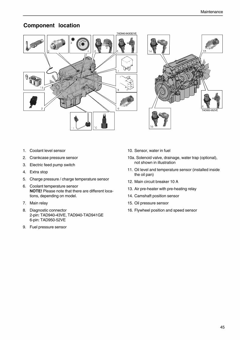
Component location
1. Coolant level sensor
2. Crankcase pressure sensor
3. Electric feed pump switch
4. Extra stop
5. Charge pressure / charge temperature sensor
6. Coolant temperature sensorNOTE! Please note that there are different loca-tions, depending on model.
7. Main relay
8. Diagnostic connector2-pin: TAD940-43VE, TAD940-TAD941GE6-pin: TAD950-52VE
9. Fuel pressure sensor
10. Sensor, water in fuel
10a. Solenoid valve, drainage, water trap (optional),not shown in illustration
11. Oil level and temperature sensor (installed insidethe oil pan)
12. Main circuit breaker 10 A
13. Air pre-heater with pre-heating relay
14. Camshaft position sensor
15. Oil pressure sensor
16. Flywheel position and speed sensor
TAD940-943GE/VE
TAD950-952VE

46
Laying up
The engine and other equipment must be laid up to prevent damage if they are not used for two months or more. Itis important that this is done in the correct manner, and nothing is forgotten. For this reason, we have compiled acheck list of the most important points.
Before the engine is taken out of service for a long period of time, an authorized Volvo Penta workshop shouldcheck it over.Have any faults and deficiencies attended to, so that the equipment is in order, ready for the next start.
WARNING! Before you start to do any maintenance work, read the “Maintenance” chapter carefully. Thiscontains instructions for doing work in a safe and correct manner.
WARNING! Some conservation oils are flammable. Some are also dangerous to breathe. Ensure good ventilation. Use a protective mask for spraying.
IMPORTANT! Remember the following when washing with a high pressure washer: Never aim the water jetat seals, rubber hoses or electrical components.
Conservation• For up to 8 months’ stoppage:
Change the oil and oil filter on the engine, thenwarm it up afterwards.
More than 8 months’ stoppage:
Conserve the lubrication and fuel systems withconservation oil. Please refer to the instructionon the next page.
• Check that the coolant offers sufficient frost pro-tection. Top up as necessary. Alternatively, youcan drain the coolant (also drain the coolant filter).
• Drain any water and contamination from the fuelfilters and fuel tank. Fill the fuel tank completely,to avoid condensation.
• Disconnect the battery cables, clean and chargethe batteries. Trickle charge the batteries whilethe equipment is laid up. A poorly charged bat-tery can freeze and burst.
• Clean the outside of the engine. Do not use a highpressure washer for engine cleaning. Touch uppaint damage with Volvo Penta original paint.
• Spray the components of the electrical systemwith water-repellent spray.
• Check and rust-proof any control cables.
• Put a note on the engine with the date, type ofconservation and the conservation oil used.
• Cover over the air filter, exhaust pipe and engineifnecessary.

Conservation of the lubrication and fuel systems for more than 8 months’ stoppage:
• Drain the engine oil and fill up with conserva-tion oil* to just over the MINmarking on the dipstick.
• Connect the fuel suction and return hoses to a1/3 full jerrican containing conservation oil*and 2/3 diesel fuel.
• Vent the fuel system.
Removing conservationpreparations• Remove any covers from the engine, air filter and
exhaust pipe.
• Top the engine up with the correct grade of oil, ifnecessary. Install a new oil filter if the filter wasnot changed during conservation.
• Install new fuel filters and vent the fuel system.
• Check the drive belt(s).
• Check the condition of all rubber hoses, andcheck the tightness of the hose clamps.
• Start the engine and run at a fast idle until about2 liters (2 US quart) of the fluid in the jerricanhave been used. Stop the engine and connectthe ordinary fuel pipes.
• Drain the engine’s conservation oil.
• Follow the other instructions on the previouspage.
* Conservation oils are sold by oil companies.
• Close the drain taps and install any draining plugs.
• Check the coolant level. Top up as necessary.
• Connect the fully charged batteries.
• Start the engine and warm it up at fast idle with noloading.
• Check that no oil, fuel or coolant leakage occurs.
Laying up

48
Fault tracingA number of symptoms and possible causes of engine malfunctions are described in the table below. Always con-tact your Volvo Penta dealer if any problems occur which you can not solve by yourself.
WARNING! Read through the safety advice for care and maintenance work in the chapter entitled “Safety-information” before you start work.
Symptoms and possible causes
The diagnosis button lamp flashes Please refer to the “Diagnostic information” chapter
Engine can not be stopped 2, 5
Starter motor does not rotate 1, 2, 3, 4, 5, 6, 7, 24
Starter motor rotates slowly 1, 2
Starter motor rotates normally but engine does not start 8, 9, 10, 11,
Engine starts but stops again 8, 9, 10, 11, 13
Engine does not reach correct operating speed at full throttle 9, 10, 11, 12, 13, 21, 25, 26
Engine runs roughly 10, 11
High fuel consumption 12, 13, 15, 25
Black exhaust smoke 12, 13
Blue or white exhaust smoke 14, 15, 22
Too low lubrication oil pressure 16
Excessive coolant temperature 17, 18, 19, 20
Too low coolant temperature 20
No, or poor charge 2, 23
1. Flat batteries
2. Poor contact/open circuit incables
3. Main switch turned off
4. Circuit breaker in junction boxfaulty
5. Faulty ignition lock
6. Faulty main relay
7. Faulty starter motor/solenoid
8. Lack of fuel:– fuel taps closed– fuel tank empty/wrong tankconnected
9. Blocked primary fuel filter / sec-ondary fuel filter (because ofcontamination, or paraffin frac-tion separation in fuel at low tem-perature)
10. Air in the fuel system
11. Water/contamination in fuel
12. Faulty unit injector
13. Insufficient air supply to engine:– blocked air filter– air leakage between turbo andengine inlet manifold– fouled compressor section inturbocharger compressor– faulty turbocharger compressor– poor engine bay ventilation
14. Excessive coolant temperature
15. Too low coolant temperature
16. Too low oil level
17. Coolant level too low
18. Air in the coolant system
19. Faulty circulation pump
20. Defective thermostat
21. Blocked intercooler
22. Too high oil level
23. Alternator drive belt slips
24. Water entry into engine
25. High back pressure in exhaust sys-tem
26. Break in “Pot+“ cable to pedal

49
Diagnostic function
• Fault codes can also be read by means of theVODIA tool. Please refer to the “VODIA User’sGuide” for advice on use.
At the same time, the fault is stored in the control unitmemory. When the fault has been attended to and theignition is switched off and on again, the fault disap-pears as active.
Inactive faults
• DCU - the fault is indicated as passive
• CIU - the diagnostic lamp goes out
• DU - the fault message disappears (inactive faultscan not be read)
• “Easy Link” - the warning lamp on the alarm panelturns off
Effect on engineEngines are affected differently, depending on the se-verity of the fault discovered by the diagnostic function.
A fault message in the form of a fault code is alwaysgenerated when a malfunction is discovered by the di-agnostic function.
Engines are affected differently, depending on the se-verity of the fault.
• The engine is not affected
• Engine idles
• Engine torque is restricted to a certain amount
• Engine is stopped
Fault codeIf the diagnostic function discovers a malfunction inthe EMS 2 system, this is reported by means of faultcodes/fault cause on the instruments.
Both inactive (rectified) and active (un-mended) faultsare stored in the control unit.
Please refer to the “Operation” heading for readingfault codes.
All fault codes are found in the fault code list, with in-formation about the reason, reaction and measures tobe taken. Please refer to the “Fault codes” chapter.
NOTE! All instruments are optional
Active faults
DCU (Display Control Unit) / DU (Display Unit)• text” !! ENGINE WARNING !!” is shown on the
display.
NOTE! You can choose the language used for the in-formation presented on the.
CIU (Control Interface Unit)• the diagnostic lamp starts to flash.
• “Easy-link” instrument (requires a CIU)- warning lamp on the alarm panel lights up- after the diagnostic button has been pressed,
the fault code is shown as text on the tachom-eter display.
DU (Display Unit)• Either “WARNING!” or “ALARM STOP” (a buzzer
sounds) will be shown on the display, dependingon the severity of the fault.
NOTE! You can choose the language used for the in-formation presented on the.
The diagnostic function monitors and checks that the EMS 2 system functions normally.
The diagnostic function has the following tasks:
• Discover and localize malfunctions
• Notify that malfunctions have been discovered
• Give advice in fault finding

OperationWhen a malfunction has occurred and the diagnosticsystem has generated one or more fault codes, theseare read out differently, depending on the equipmentused. Please refer to “Fault codes”.
If the system indicates that a fault code has beenset:
1. Cut engine speed to idle, or shut the engine off.
2. For DCU/DURead the fault code set from the display, pleaserefer to “Reading fault cause via the DCU” or“Reading fault cause via DU”.
For CIUPress the diagnostic button and read the faultcode that has been set, by observing the flashingof the diagnostic lamp. Please refer to “Readingfault codes via the diagnostic lamp, CIU”
3. Look up the fault code/cause in the “Fault Code”chapter and take the recommended measures.
Reading fault cause via the DCU (DisplayControl Unit)When a fault code is set, the following text is shownon the display:
“!! ENGINE WARNING !!”
alternated with
“Press SEL for information”.
NOTE! You can choose the language used for the in-formation presented on the.
Read the fault code as follows:
1. Press the SEL button (to come to the error list.The fault list shows:- Operation hours- Fault cause- Active/inactive
2. Look up the fault code in the “Fault Code” chapterand take the recommended measures.
3. Press the ESC button to leave the fault list.
NOTE! To enter the fault list when no fault code hasbeen set, press the SEL button and select “Diagnos-tics” from the menu.
Reading fault cause via the DU (DisplayUnit)Depending on the severity of the faults, one of the fol-lowing messages will appear on the display: “WARN-ING!” or “ALARM STOP” (a buzzer sounds).
1. Press any button to come to the fault list.
The fault list shows:- Operation hours- Fault cause
2. Look up the fault code in the “Fault Code” chapterand take the recommended measures.
3. Press ACK to confirm the fault code. The displaybackground will change color (the buzzer stopssounding).
4. Press EXIT to leave the fault list.

Reading fault codes via the diagnosticlamp on the instrument panel, CIUWhen the system has discovered a malfunction, thediagnostic lamp starts to flash. If the diagnostic but-ton is depressed and then released, a fault code isflashed out.The fault code consists of two groups of flashes, sepa-rated by a pause of two seconds. A fault code is ob-tained by counting the number of flashes in each group.
Example: pause = Fault code 2.4
The fault code is stored and can be read as long as themalfunction remains. You can find information aboutcause, reaction and actions in the “Fault Code” chapter.
Read the fault code as follows:
1. Press the diagnostic button.
2. Release the diagnostic button and make a note ofthe fault that is flashed out.
3. Repeat items 1-2. A new fault code is flashed outif more are stored. Repeat until the first fault codeis repeated.
4. Look up the fault code in the “Fault Code” chapterand take the recommended measures.
NOTE! When the first fault code is repeated, all faultcodes have been read out.If the diagnostic button is pressed after the fault hasbeen mended and the fault codes have been erased,code 1.1 “No fault” will be displayed.
Reading fault codes via ”Easy Link” in-strument (only with CIU)When the system has discovered a malfunction, thediagnostic lamp starts to flash and the fault code willshow in the display of the tachometer.
1. Press the diagnostic button, the fault code willshow in the display of the tachometer.
2. Look up the fault code in the “Fault Code” chapterand take the recommended measures.
3. When the fault has been attended to, the faultcode disappears from the display and the diagnos-tic lamp goes out.
Erasing fault codesFault codes must be erased by means of the VODIAtool.

Fault codes
WARNING! Read through the safety advice for care and maintenance work in the “Safety information” chap-ter before you start work.
NOTE! Reading the fault codes below, such as Code 2.1. PID 97. means that 2.1 is the flashing code indicatedby the diagnostic lamp on the instrument box. PID 97 is read with the VODIA diagnostic tool. Please refer to“Reading fault codes”.
NOTE! Please refer to “Wiring schedule CIU and DCU” for references to the sleeves in the electrical connectorson the engine control unit.
Code 1.1 No faults
There are no active faults.
Code 2.1, PID / SPN 97, Water in fuel
Cause:
• Water in fuel.
Reaction:
• None.
Remedy:
• Empty the primary fuel filter.
Code 2.2, PID / SPN 111. Coolant level
Cause:
• Low coolant level.
Reaction:
• Warning indication.
• Engine control module reduces engine power (un-less the protection has been shut off with theVODIA diagnostic tool).
Remedy:
• Check the coolant level.
• Check coolant level monitor function.
Code 2.3, PID / SPN 111. Coolant level sensor
Cause:
• Short circuit to positive (+).
• Fault in sensor.
Reaction:
• None.
Remedy:
• Check that the coolant level sensor cable is notdamaged.
• Check coolant level sensor function.
Code 2.4, SID21 / SPN 637Flywheel speed sensor
Cause:
• No signal.
• Abnormal frequency.
• “Intermittent” signal from the sensor.
• Fault in sensor.
Reaction:
• Engine is very difficult to start and runs roughlywhen it starts.
Remedy:
• Check that the sensor connector is correctly in-stalled.
• Check that the engine speed sensor cable is notdamaged.
• Check that the engine speed sensor is correctlyinstalled in the flywheelhousing.
• Check engine speed sensor function.

53
Fault codes
Code 2.5, SID22 / SPN 636Camshaft drive speed sensor
Cause:
• No signal.
• Abnormal frequency.
• Fault in sensor.
Reaction:
• Engine takes longer to start than normal. Engineruns normally when running.
Remedy:
• Check that the engine speed sensor connector iscorrectly installed.
• Check that the engine speed sensor cable is notdamaged.
• Check that the engine speed sensor is correctlyinstalled in the upper timing gear cover.
• Check engine speed sensor function.
Code 2.6, PID / SPN 190, Code 2.6 Engine speed
Cause:
• Engine speed too high.
Reaction:
• None.
Remedy:
• After the engine has stopped, look for the reasonfor the high speed.
Code 2.8, PPID 132 / SPN 608,Speed potentiometer connected to CIU
Cause:
• Shorted to plus (+) or minus (-).
• Fault in sensor.
Reaction:
• Engine goes to idle.
If you release the accelerator first, and the pressit down again, the engine can be forced to run us-ing the idle contact.
Remedy:
• Check that the potentiometer has been connectedcorrectly.
• Check that the cable harness to the potentiometerhas not been damaged.
• Check the potentiometer function.
Code 2.9, PID / SPN 97, Indicator for water in fuel
Cause:
• Short circuit
• Open circuit.
• Fault in indicator.
Reaction:
• None.
Remedy:
• Check the indicator cables for breaks and shortcircuits.
• Check indicator function. Change indicator as nec-essary
Code 3.1, PID / SPN 100, Oil pressure sensor
Cause:
• Short circuit to positive (+) or earth (ground) (–).
• Open circuit.
Reaction:
• None.
Remedy:
• Check that the oil pressure sensor cable is notdamaged.
• Check that the oil pressure sensor is correctlyconnected.
Code 3.2, PID / SPN 105Charge air temperature sensor
Cause:
• Short circuit to positive (+) or earth (ground) (–).
• Open circuit.
Reaction:
• None.
Remedy:
• Check that the charge air temperature sensor con-nector is correctly installed.
• Check that the charge air temperature sensor ca-ble is not damaged.
• Check that the charge air temperature sensor iscorrectly installed.
• Check charge air temperature sensor function.
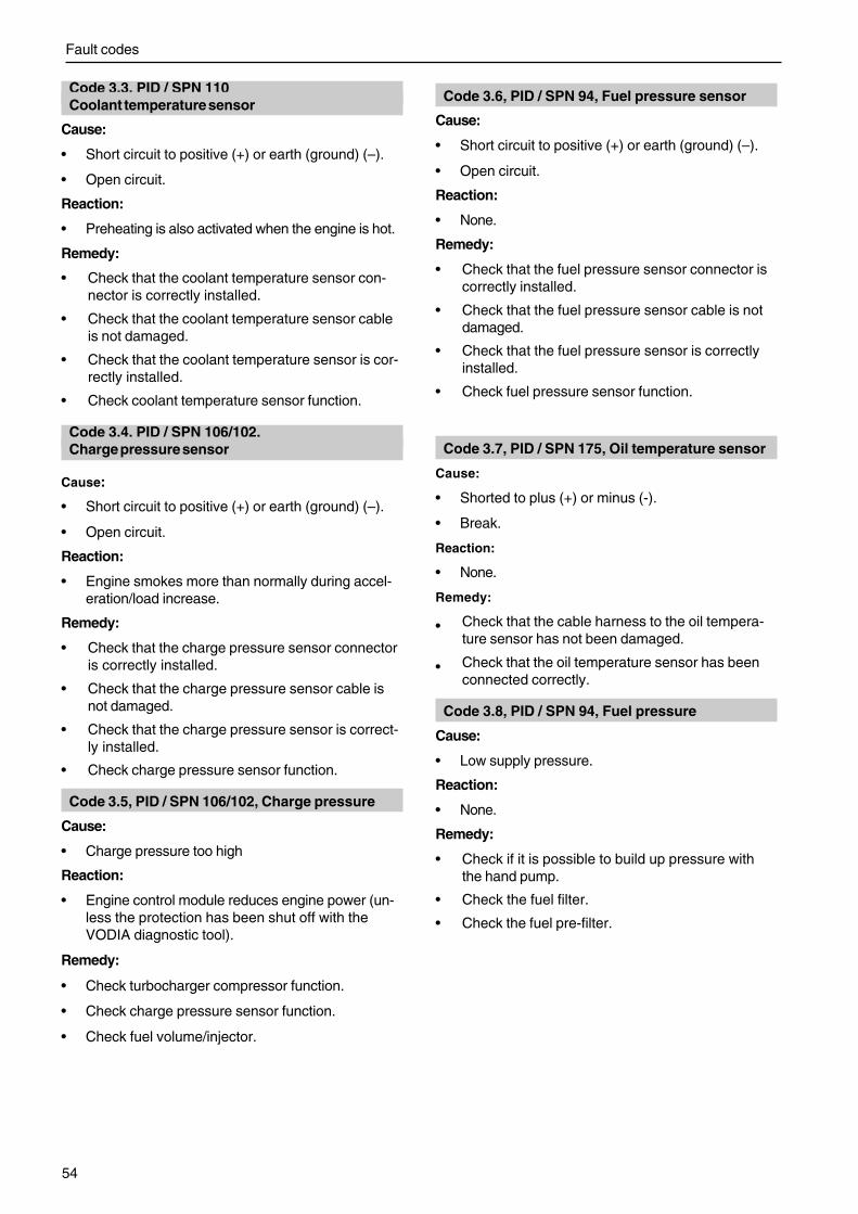
Fault codes
54
Code 3.3, PID / SPN 110Coolant temperature sensor
Cause:
• Short circuit to positive (+) or earth (ground) (–).
• Open circuit.
Reaction:
• Preheating is also activated when the engine is hot.
Remedy:
• Check that the coolant temperature sensor con-nector is correctly installed.
• Check that the coolant temperature sensor cableis not damaged.
• Check that the coolant temperature sensor is cor-rectly installed.
• Check coolant temperature sensor function.
Code 3.4, PID / SPN 106/102,Charge pressure sensor
Cause:
• Short circuit to positive (+) or earth (ground) (–).
• Open circuit.
Reaction:
• Engine smokes more than normally during accel-eration/load increase.
Remedy:
• Check that the charge pressure sensor connectoris correctly installed.
• Check that the charge pressure sensor cable isnot damaged.
• Check that the charge pressure sensor is correct-ly installed.
• Check charge pressure sensor function.
Code 3.5, PID / SPN 106/102, Charge pressure
Cause:
• Charge pressure too high
Reaction:
• Engine control module reduces engine power (un-less the protection has been shut off with theVODIA diagnostic tool).
Remedy:
• Check turbocharger compressor function.
• Check charge pressure sensor function.
• Check fuel volume/injector.
Code 3.6, PID / SPN 94, Fuel pressure sensor
Cause:
• Short circuit to positive (+) or earth (ground) (–).
• Open circuit.
Reaction:
• None.
Remedy:
• Check that the fuel pressure sensor connector iscorrectly installed.
• Check that the fuel pressure sensor cable is notdamaged.
• Check that the fuel pressure sensor is correctlyinstalled.
• Check fuel pressure sensor function.
Code 3.7, PID / SPN 175, Oil temperature sensor
Cause:
• Shorted to plus (+) or minus (-).
• Break.
Reaction:
• None.
Remedy:
• Check that the cable harness to the oil tempera-ture sensor has not been damaged.
• Check that the oil temperature sensor has beenconnected correctly.
Code 3.8, PID / SPN 94, Fuel pressure
Cause:
• Low supply pressure.
Reaction:
• None.
Remedy:
• Check if it is possible to build up pressure withthe hand pump.
• Check the fuel filter.
• Check the fuel pre-filter.

55
Fault codes
Code 3.9, PID / SPN 158, Battery voltage, EMS
Cause:
• Faulty alternator.
• Faulty battery, battery cables.
Reaction:
• None.
Remedy:
• Check the supply voltage from the control unit.
Code 4.8, PPID 6/ SPN 520195, Stop input EMS
Cause:
• Short circuit to negative (-).
• Open circuit.
Reaction:
• Engine can only be stopped with the auxiliarystop.
Remedy:
• Check that the starter switch connections are notdamaged.
Code 5.2, PPID 4 / SPN 520194, Starter input CIU
Cause:
• Shorted to minus (-).
• Activated for too long.
Reaction:
• The engine cannot be started.
• The engine starts immediately when ignition is tur-ned on.
Remedy:
• Check that connections to the ignition key havenot been damaged.
• Check that the cable harness to the ignition keyhas not been damaged.
Code 5.3, PPID 6/ SPN 970, Stop input CIU
Cause:
• Short circuit to negative (-).
• Open circuit.
• Activated for too long time.
Reaction:
• Engine can only be stopped with the auxiliary stop(AUX STOP) on engine.
• Engine stops. A fault code is displayed for 40seconds and the engine can not be started duringthis time. When a fault code is active, the enginecan be started but not stopped.
Remedy:
• Check that the starter switch connections are notdamaged.
• Check that the ignition switch cable is notdamaged.
Code 5.4, PID 45/ SPN 626, Preheating relay
Cause:
• Short circuit to positive (+) or earth (ground) (–).
• Open circuit.
Reaction:
• Preheating can not be activated.
• Preheating is constantly connected.
Remedy:
• Check that the relay input cable is not damaged.
• Check relay function.
Code 5.7, PID / SPN 98, Oil level
Cause:
• Oil level is too low.
Reaction:
• Warning indication.
Remedy:
• Check the oil level.
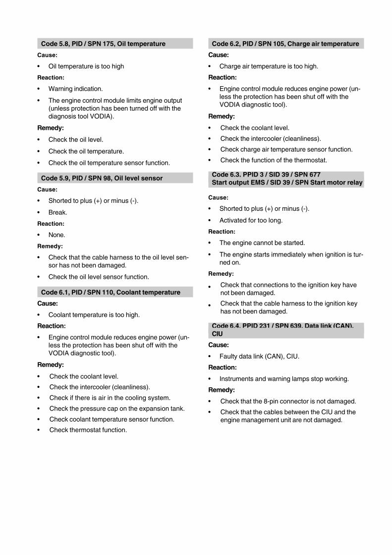
Code 5.8, PID / SPN 175, Oil temperature
Cause:
• Oil temperature is too high
Reaction:
• Warning indication.
• The engine control module limits engine output(unless protection has been turned off with thediagnosis tool VODIA).
Remedy:
• Check the oil level.
• Check the oil temperature.
• Check the oil temperature sensor function.
Code 5.9, PID / SPN 98, Oil level sensor
Cause:
• Shorted to plus (+) or minus (-).
• Break.
Reaction:
• None.
Remedy:
• Check that the cable harness to the oil level sen-sor has not been damaged.
• Check the oil level sensor function.
Code 6.1, PID / SPN 110, Coolant temperature
Cause:
• Coolant temperature is too high.
Reaction:
• Engine control module reduces engine power (un-less the protection has been shut off with theVODIA diagnostic tool).
Remedy:
• Check the coolant level.
• Check the intercooler (cleanliness).
• Check if there is air in the cooling system.
• Check the pressure cap on the expansion tank.
• Check coolant temperature sensor function.
• Check thermostat function.
Code 6.2, PID / SPN 105, Charge air temperature
Cause:
• Charge air temperature is too high.
Reaction:
• Engine control module reduces engine power (un-less the protection has been shut off with theVODIA diagnostic tool).
Remedy:
• Check the coolant level.
• Check the intercooler (cleanliness).
• Check charge air temperature sensor function.
• Check the function of the thermostat.
Code 6.3, PPID 3 / SID 39 / SPN 677Start output EMS / SID 39 / SPN Start motor relay
Cause:
• Shorted to plus (+) or minus (-).
• Activated for too long.
Reaction:
• The engine cannot be started.
• The engine starts immediately when ignition is tur-ned on.
Remedy:
• Check that connections to the ignition key havenot been damaged.
• Check that the cable harness to the ignition keyhas not been damaged.
Code 6.4, PPID 231 / SPN 639, Data link (CAN),CIU
Cause:
• Faulty data link (CAN), CIU.
Reaction:
• Instruments and warning lamps stop working.
Remedy:
• Check that the 8-pin connector is not damaged.
• Check that the cables between the CIU and theengine management unit are not damaged.

57
Fault codes
Code 6.5, PPID 231 / SPN 639,Data link (CAN), EMS 2
Cause:
• Internal fault in control module.
Reaction:
• Engine not operating: engine can not be started.Engine operating: engine idles and can only bestopped with the auxiliary stop (AUX-stop).
Remedy:
• Check that the 8-pin connector is not damaged.
• Check that the cables between the CIU and theengine management unit are not damaged.
• Check that sleeves 11 and 12 in the connector onthe CIU are not damaged.
Code 6.6, PID / SPN 100, Oil pressure
Cause:
• Oil pressure is too low.
Reaction:
• Engine control module reduces engine power (un-less the protection has been shut off with theVODIA diagnostic tool).
Remedy:
• Check oil level.
• Check that the air filters are not blocked.
• Check system pressure valves and safety valvesin the oil system.
• Check oil pressure sensor function.
Code 6.7, PPID 8 / SPN 520192,Piston cooling pressure
Cause:
• Piston cooling pressure is too low.
Reaction:
• Engine stopped. The fault code is de-activated atengine speeds below 1000 rpm.
Remedy:
• Check that the oil pressure in the engine exceeds175 kPa (25.4 psi).
Code 6.8, PPID 8 / SPN 520192,Piston cooling pressure sensor
Cause:
• Shorted to plus (+) or minus (-).
• Break.
Reaction:
• None.
Remedy:
• Check that the piston cooling pressure sensorcontact is correctly installed.
• Check that the cable harness to the piston coolingpressure sensor has not been damaged.
• Check the piston cooling pressure sensor func-tionality.
Code 6.9, PID / SPN 158, Battery voltage, CIU
Cause:
• Short circuit to negative (-).
• Faulty alternator.
• Faulty battery, battery cables.
Reaction:
• Problems in engine starting.
Remedy:
• Check the supply voltage from the control unit.
• Check the battery.
• Check the alternator.
• Check the 8-pin contact.
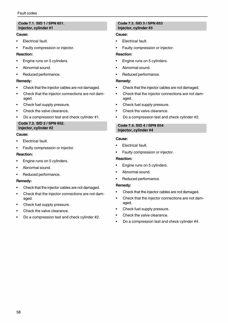
Fault codes
58
Code 7.1, SID 1 / SPN 651,Injector, cylinder #1
Cause:
• Electrical fault.
• Faulty compression or injector.
Reaction:
• Engine runs on 5 cylinders.
• Abnormal sound.
• Reduced performance.
Remedy:
• Check that the injector cables are not damaged.
• Check that the injector connections are not dam-aged.
• Check fuel supply pressure.
• Check the valve clearance.
• Do a compression test and check cylinder #1.
Code 7.2, SID 2 / SPN 652,Injector, cylinder #2
Cause:
• Electrical fault.
• Faulty compression or injector.
Reaction:
• Engine runs on 5 cylinders.
• Abnormal sound.
• Reduced performance.
Remedy:
• Check that the injector cables are not damaged.
• Check that the injector connections are not dam-aged.
• Check fuel supply pressure.
• Check the valve clearance.
• Do a compression test and check cylinder #2.
Code 7.3, SID 3 / SPN 653Injector, cylinder #3
Cause:
• Electrical fault.
• Faulty compression or injector.
Reaction:
• Engine runs on 5 cylinders.
• Abnormal sound.
• Reduced performance.
Remedy:
• Check that the injector cables are not damaged.
• Check that the injector connections are not dam-aged.
• Check fuel supply pressure.
• Check the valve clearance.
• Do a compression test and check cylinder #3.
Code 7.4, SID 4 / SPN 654Injector, cylinder #4
Cause:
• Electrical fault.
• Faulty compression or injector.
Reaction:
• Engine runs on 5 cylinders.
• Abnormal sound.
• Reduced performance.
Remedy:
• Check that the injector cables are not damaged.
• Check that the injector connections are not dam-aged.
• Check fuel supply pressure.
• Check the valve clearance.
• Do a compression test and check cylinder #4.

59
Fault codes
Code 7.5, SID 5 / SPN 655Injector, cylinder #5
Cause:
• Electrical fault.
• Faulty compression or injector.
Reaction:
• Engine runs on 5 cylinders.
• Abnormal sound.
• Reduced performance.
Remedy:
• Check that the injector cables are not damaged.
• Check that the injector connections are not dam-aged.
• Check fuel supply pressure.
• Check the valve clearance.
• Do a compression test and check cylinder #5.
Code 7.6, SID 6 / SPN 656Injector, cylinder #6
Cause:
• Electrical fault.
• Faulty compression or injector.
Reaction:
• Engine runs on 5 cylinders.
• Abnormal sound.
• Reduced performance.
Remedy:
• Check that the injector cables are not damaged.
• Check that the injector connections are not dam-aged.
• Check fuel supply pressure.
• Check the valve clearance.
• Do a compression test and check cylinder #6.
Code 7.7, PID / SPN 153Crankcase ventilation pressure
NOTE! Only TAD950-952VE.
Cause:
• Crankcase ventilation pressure too high.
Reaction:
• The engine is shut down (if the protection has notbeen shut off by the parameter tool).
Remedy:
• Check whether the crankcase ventilation is bloc-ked.
• Check whether cylinder liner, piston or piston ringsare worn or damaged.
Code 7.8, PID / SPN 153,Crankcase ventilation pressure sensor
Cause:
• Shorted to plus (+) or minus (-).
• Break.
Reaction:
• None.
Remedy:
• Check that the crankcase ventilation pressuresensor contact is correctly installed.
• Check that the cable harness to the crankcaseventilation pressure sensor has not been dam-aged.
• Check crankcase ventilation pressure sensorfunction.
Code 9.2, SID250 / SPN 608Faulty data link (J1587)
Cause:
• Faulty data link.
Reaction:
• None.
Remedy:
• Check that the 8-pin connector is not damaged.
• Check that the cables between the CIU/DCU andthe engine management unit are not damaged.

Fault codes
60
Code 9.3, SID 232 / SPN 620Power supply to sensor
Cause:
• Shortcut.
• Fault in sensor.
Reaction:
• Faulty values in oil pressure and charge air pres-sure sensors.
• Fault code for oil pressure- and charge air pres-sure sensor.
• Low engine output.
• The instrument shows zero oil pressure and boostpressure.
Remedy:
• Check that the cable harness to oil pressure andcharge air pressure sensor has not been dam-aged.
• Check oil pressure and charge air pressure sen-sors.
Code 9.8, SID 253 / SPN 630Data set memory EEPROM, CIU
Cause:
• Internal fault in control module
• Programming faulty.
Reaction:
• Engine does not start.
Remedy:
• Re-program the control module. If the fault re-mains, change the control module.
Code 9.8, PPID 254 / SPN 629Fault in control unit, CIU
Cause:
• Faulty EEPROM, CIU.
• Faulty flash memory, CIU.
• Fault in control module, CIU
Reaction:
• CIU returns to factory setting.
• Engine goes to idle.
• Engine can not be started.
Remedy:
• Re-program the unit
Code 9.9, SID 240 / SPN 639, Memory fault
Cause:
• Memory fault in engine management system.
Reaction:
• Engine might not start.
Remedy:
• Re-program the unit.
• Change engine control unit (EMS).
Code 9.9, SID 253 / SPN 630Data set memory EEPROM, EMS
Cause:
• Internal fault in control module
• Programming faulty.
Reaction:
• Engine does not start.
Remedy:
• Re-program the control module. If the fault re-mains, change the control module.

61
Fault codes
Code 9.9, SID 254 / SPN 629Control module EMS
Cause:
• Internal fault in control module.
Reaction:
• Engine misfires.
• Engine does not start.
Remedy:
• Change engine control unit.
PPID 19 / SPN 2791, Internal EGR
Cause:
• Fault in cable harness (boost pressure sensor).
• Mechanical fault on the IEGR
Reaction:
• Engine control module reduces engine power (un-less the protection has been shut off with theVODIA diagnostic tool).
Remedy:
• Check cable harness (boost pressure sensor).
• Check the IEGR.

62
Type designation TAD940GE TAD941GE
Power, Prime/Stand-by Please refer to the sales literature
Torque, Prime/Stand-by Please refer to the sales literature
Compression ratio 20.2:1 17.4:1
Low idle (rpm) 600-1200 600-1200
High idle (rpm) 1500-1620 1500-16201800-1920 1800-1920
Highest full load speed (rpm) 1500/1800 1500/1800
No. of valves 24 24
No. of cylinders 6 6
Cylinder bore, mm (inch) 120 (4.72) 120 (4.72)
Stroke, mm (inch) 138 (5.43) 138 (5.43)
Swept volume, dm3 (US quart) 9.36 (9.89) 9.36 (9.89)
Weight, dry, kg (lb) 1015 (2238) 1015 (2238)
Weight, wet, kg (lb) 1065 (2348) 1065 (2348)
Injection sequence 1-5-3-6-2-4 1-5-3-6-2-4
Technical data
General
Type designation TAD940VE TAD941VE TAD942VE TAD943VE
Power Please refer to the sales literature
Torque Please refer to the sales literature
Compression ratio 20.2:1 20.2:1 20.2:1 20.2:1
Low idle (rpm) 600 600 600 600
High idle (rpm) 2250 2250 2250 2250
No. of valves 24 24 24 24
No. of cylinders 6 6 6 6
Cylinder bore, mm (inch) 120 (4.72) 120 (4.72) 120 (4.72) 120 (4.72)
Stroke, mm (inch) 138 (5.43) 138 (5.43) 138 (5.43) 138 (5.43)
Swept volume, dm3 (US quart) 9.36 (9.89) 9.36 (9.89) 9.36 (9.89) 9.36 (9.89)
Weight, dry, kg (lb) 1015 (2238) 1015 (2238) 1015 (2238) 1015 (2238)
Weight, wet, kg (lb) 1065 (2348) 1065 (2348) 1065 (2348) 1065 (2348)
Injection sequence 1-5-3-6-2-4 1-5-3-6-2-4 1-5-3-6-2-4 1-5-3-6-2-4

Technical data
63
Type designation TAD950VE TAD951VE TAD952VE
Power Please refer to the sales literature
Torque Please refer to the sales literature
Compression ratio 20.2:1 20.2:1 20.2:1
Low idle (rpm) 600 600 600
High idle (rpm) 2250 2250 2250
No. of valves 24 24 24
No. of cylinders 6 6 6
Cylinder bore, mm (inch) 120 (4.72) 120 (4.72) 120 (4.72)
Stroke, mm (inch) 138 (5.43) 138 (5.43) 138 (5.43)
Swept volume, dm3 (US quart) 9.36 (9.89) 9.36 (9.89) 9.36 (9.89)
Weight, dry, kg (lb) 1015 (2238) 1015 (2238) 1015 (2238)
Weight, wet, kg (lb) 1065 (2348) 1065 (2348) 1065 (2348)
Injection sequence 1-5-3-6-2-4 1-5-3-6-2-4 1-5-3-6-2-4
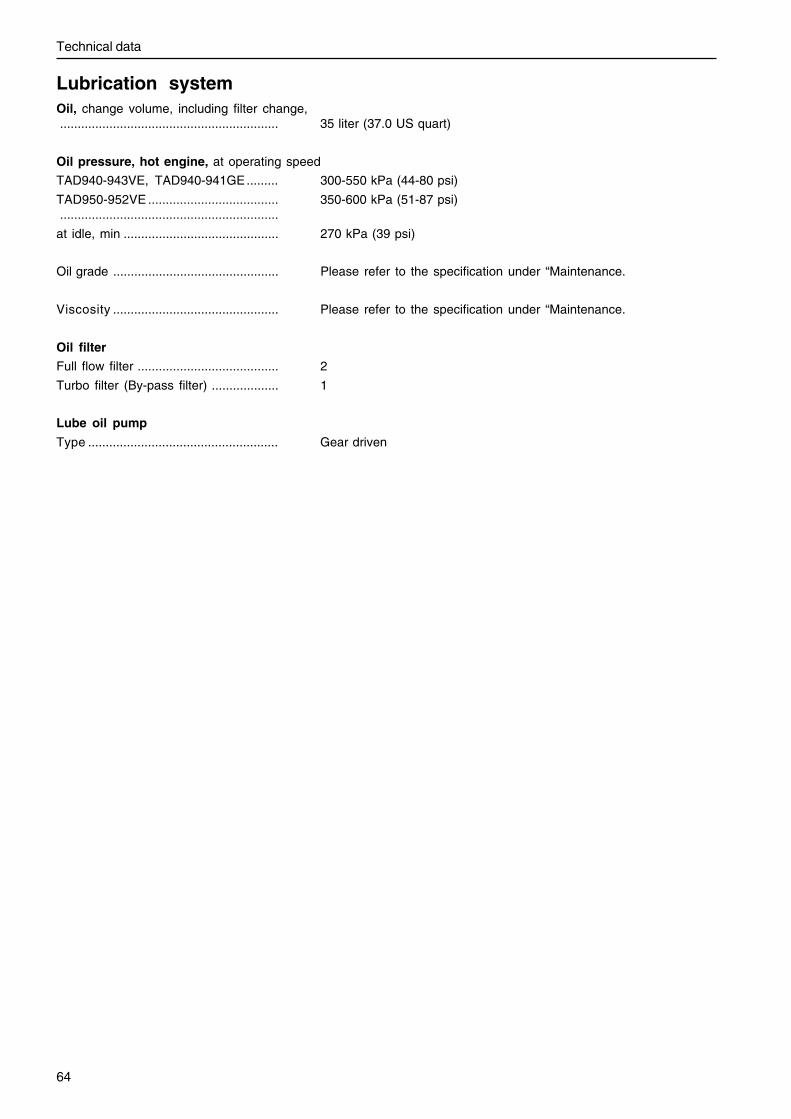
64
Technical data
Lubrication systemOil, change volume, including filter change,.............................................................. 35 liter (37.0 US quart)
Oil pressure, hot engine, at operating speed
TAD940-943VE, TAD940-941GE......... 300-550 kPa (44-80 psi)
TAD950-952VE ..................................... 350-600 kPa (51-87 psi)..............................................................
at idle, min ............................................ 270 kPa (39 psi)
Oil grade ............................................... Please refer to the specification under “Maintenance.
Viscosity ............................................... Please refer to the specification under “Maintenance.
Oil filter
Full flow filter ........................................ 2
Turbo filter (By-pass filter) ................... 1
Lube oil pump
Type ...................................................... Gear driven

Technical data
65
Fuel systemFeed pumpSupply pressure at 600 rpm ................. min 100 kPa (14.5 psi)
Supply pressure at 1200 rpm ............... min 300 kPa (43.5 psi)
Supply pressure at full load ................. min 300 kPa (43.5 psi)
By - pass valve
Opening pressure ................................. 400-550 kPa (58-79.7 psi)
Fuel specificationThe fuel must comply with national and international standards for commercially supplied fuels, such as:
EN 590 (with nationally adapted environmental and cold requirements)
ASTM D 975 No 1 - D and 2 - D
JIS KK 2204
Sulfur content: Complying with legal requirements in each country.
Low density fuel (urban diesel in Sweden and city diesel in Finland) can cause a loss of up to 5% of power and anincrease in fuel consumption of about 2-3%.
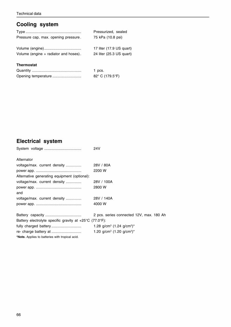
66
Technical data
Electrical systemSystem voltage .................................... 24V
Alternator
voltage/max. current density ............... 28V / 80A
power app. ............................................ 2200 W
Alternative generating equipment (optional):
voltage/max. current density ............... 28V / 100A
power app. ............................................ 2800 W
and
voltage/max. current density ............... 28V / 140A
power app. ............................................ 4000 W
Battery capacity ................................... 2 pcs. series connected 12V, max. 180 Ah
Battery electrolyte specific gravity at +25°C (77.0°F):
fully charged battery ............................. 1.28 g/cm3 (1.24 g/cm3)*
re- charge battery at ............................. 1.20 g/cm3 (1.20 g/cm3)**Note. Applies to batteries with tropical acid.
Cooling systemType ...................................................... Pressurized, sealed
Pressure cap, max. opening pressure . 75 kPa (10.8 psi)
Volume (engine).................................... 17 liter (17.9 US quart)
Volume (engine + radiator and hoses) . 24 liter (25.3 US quart)
Thermostat
Quantity ................................................ 1 pcs.
Opening temperature ............................ 82° C (179.5°F)

Notes...........................................................................................................................................................................................
...........................................................................................................................................................................................
...........................................................................................................................................................................................
...........................................................................................................................................................................................
...........................................................................................................................................................................................
...........................................................................................................................................................................................
...........................................................................................................................................................................................
...........................................................................................................................................................................................
...........................................................................................................................................................................................
...........................................................................................................................................................................................
...........................................................................................................................................................................................
...........................................................................................................................................................................................
...........................................................................................................................................................................................
...........................................................................................................................................................................................
...........................................................................................................................................................................................
...........................................................................................................................................................................................
...........................................................................................................................................................................................
...........................................................................................................................................................................................
...........................................................................................................................................................................................
...........................................................................................................................................................................................
...........................................................................................................................................................................................
...........................................................................................................................................................................................
...........................................................................................................................................................................................
...........................................................................................................................................................................................
...........................................................................................................................................................................................
...........................................................................................................................................................................................

Please note that this offer is valid for 12 months from the date of deli-very of the engine, after this it is subject to availability.
Post or fax this coupon to:Document & Distribution Cen-terOrder DepartmentARU2, Dept. 64620SE-405 08 GöteborgSwedenFax: +46 31 545 772Orders can also be placed viathe Internet:http://www.volvopenta.com/manual/coupon
Yes please,I would like an operator’s manual in English at no charge.
Publication number: 7745259
Name
Address
Country 4220
0/61
5001
/155
0999
0019
2
✂
Bitte beachten Sie, dass das Angebot für die Dauer von 12 Monaten ab demLieferdatum des Motors gilt, danach nur noch bis zum Aufbrauchen des La-gerbestandes.
Schicken Sie den Couponper Post oder als Fax an:Document & Distribution CenterOrder DepartmentARU2, Dept. 64620SE-405 08 GöteborgSchwedenFax: +46 31 545 772Die Bestellung kann auch überdas Internet erfolgen:http://www.volvopenta.com/manual/coupon
Ja danke,ich will kostenlos eine Betriebsanleitung in deutscher Sprache erhalten.
Publikationsnummer: 7745261
Name
An-schrift
Land 4220
0/61
5001
/155
0999
0019
2
✂
Noter que l’offre est valable 12 mois à partir de la date de livraison dumoteur, puis seulement dans la mesure des stocks disponibles.
Envoyez ou faxez le bon decommande à:Document & Distribution CenterOrder DepartmentARU2, Dept. 64620SE-405 08 GöteborgSuèdeFax: +46 31 545 772Vous pouvez également passerla commande par Internet:http://www.volvopenta.com/manual/coupon
Oui merci,Je souhaite recevoir un manuel d’instructions gratuit en français.Numéro de publication: 7745262
Nom
Adresse
Pays 4220
0/61
5001
/155
0999
0019
2
✂

Notare che la validità dell’offerta è garantita solo per 12 mesi dalla consegnadel motore, dopodiché si procederà fino ad esaurimento scorte.
Spedire il tagliando per posta oper fax a:Document & Distribution CenterOrder DepartmentARU2, Dept. 64620SE-405 08 GöteborgSveziaFax: +46 31 545 772L’ordinazione può essere fattaanche su Internet:http://www.volvopenta.com/manual/coupon
Sì, grazie,desidero ricevere gratuitamente un manuale d’istruzioni in lingua italiana.
Public. No.: 7745264
Nome e Cognome
Indirizzo
Paese 4220
0/61
5001
/155
0999
0019
2
✂
Observe que la oferta es válida durante 12 meses a partir de la fecha de entre-ga del motor. A partir de la fecha de finalización de la oferta, la misma es váli-da siempre que haya existencias.
Franquear o enviar fax a:Document & Distribution Cen-terOrder DepartmentARU2, Dept. 64620SE-405 08 GöteborgSueciaFax: +46 31 545 772El pedido puede hacerse tam-bién por internet:http://www.volvopenta.com/manual/coupon
Sí gracias,deseo recibir gratuitamente un libro de instrucciones en español.
Número de publicación: 7745263
Nombre
Direc-ción
País 4220
0/61
5001
/155
0999
0019
2
✂
Observera att erbjudandet gäller i 12 månader från motornsleveransdatum, därefter endast i mån av tillgång.
Posta eller faxa kupongen till:Dokument & Distribution centerOrdermottagningenARU2, Avd. 64620SE-405 08 GöteborgSverigeFax: +46 31 545 772Beställningen kan även görasvia internet:http://www.volvopenta.com/manual/coupon
Ja tack,jag vill kostnadsfritt ha en instruktionsbok på svenska.
Publikationsnummer: 7745258
Namn
Adress
Land 4220
0/61
5001
/155
0999
0019
2
✂

Denk eraan dat de aanbieding geldt tot 12 maanden na levering van demotor, daarna nog slechts indien beschikbaar.
Stuur of fax de coupon naar:Document & Distribution CenterOrder DepartmentARU2, Dept. 64620SE-405 08 GöteborgZwedenFax: +46 31 545 772U kunt ook bestellen viainternet:http://www.volvopenta.com/manual/coupon
Ja graag,Ik wil kosteloos een instructieboek in het Nederlands ontvangen.
Publicatienummer: 7745266
Naam
Adres
Land 4220
0/61
5001
/155
0999
0019
2
✂
Ota huomioon, että tarjous on voimassa 1 vuoden ajanmoottorin luovutuspäivämäärästä, sen jälkeen vaintuotteen saatavuuden perusteella.
Postita tai faksaa kuponkiosoitteella:Document & Distribution CenterOrder DepartmentARU2, Dept. 64620SE-405 08 GöteborgRuotsiFax: +46 31 545 772Tilauksen voi tehdä myösInternetissä:http://www.volvopenta.com/manual/coupon
Kyllä kiitos,haluan suomenkielisen ohjekirjan veloituksetta.
Julkaisunumero: 7745264
Nimi
Osoite
Maa 4220
0/61
5001
/155
0999
0019
2
✂
Notar que a oferta é válida por um período de 12 meses a partir da data de ent-rega do motor. Depois desse período, a oferta é válida consoante a disponibili-dade.
Envie o talão pelo correio ouum fax para:Document & Distribution CenterOrder DepartmentARU2, Dept. 64620SE-405 08 GöteborgSuéciaFax: +46 31 545 772A encomenda também podeser feita através da Internet:http://www.volvopenta.com/manual/coupon
Sim, obrigado(a)!Gostaria de receber gratuitamente um manual de instruções em português.
Número de publicação: 7745267
Nome
Endereço
País 4220
0/61
5001
/155
0999
0019
2
✂
������������� ����� ������������� ��� � ��������������������������������������������� ���� !��� � � ��������
���������� ���� �� ���������� �������� �������� ������ �� �� ��� ����������� ������ ����
Document & Distribution CenterOrder DepartmentARU2, Dept. 64620SE-405 08 GöteborgSwedenFax: +46 31 545 772�������� ����� �� ����� ������� ���� �� �!� ��� "#$%&'#%$( �� ���������
http://www.volvopenta.com/manual/coupon
������������������� ������������������������������������������������������������
����������������� !"#$%�����
������
���� 4220
0/61
5001
/155
0999
0019
2
✂
������������� ���������������� ������ ������������� ����������������������� �� �����!�����������������"� ������� � �#
���������������� ��������������� �����Document & Distribution CenterOrder DepartmentARU2, Dept. 64620SE-405 08 GöteborgSwedenFax: +46 31 545 772�������������� ���������������� ��� ���http://www.volvopenta.com/manual/coupon
������������������������������ �������������� ������������������� ������������������������������
!��
"���
#����� 4220
0/61
5001
/155
0999
0019
2
✂


7745259
Eng
lish
11-2005