Volute pumps - PSI Prolew Inc.psiprolew.com/doc/Flowserve-SIHIHotwaterpumps/...Catalogue_ZHN.pdf ·...
14
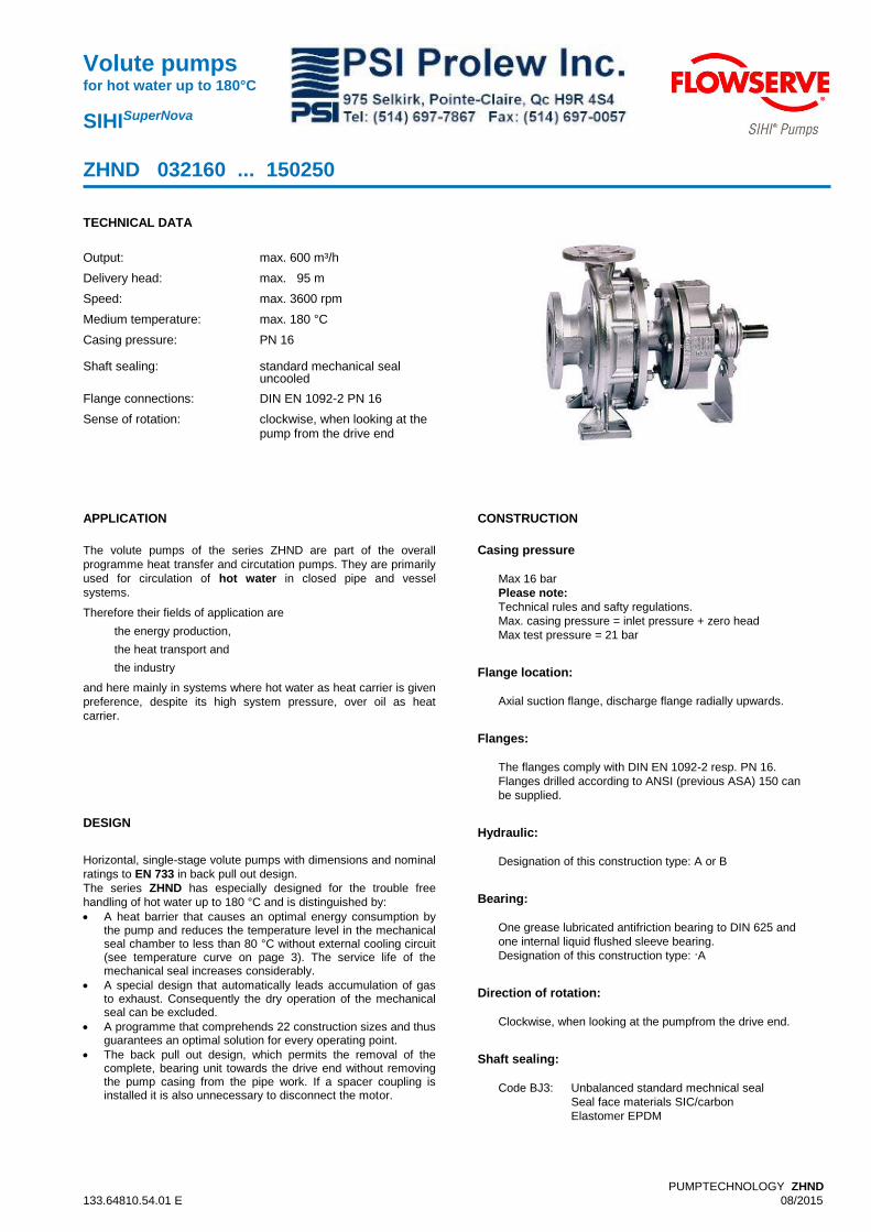
Volute pumps for hot water up to 180°C SIHI SuperNova ZHND 032160 ... 150250 PUMPTECHNOLOGY ZHND 133.64810.54.01 E 08/2015 TECHNICAL DATA Output: max. 600 m³/h Delivery head: max. 95 m Speed: max. 3600 rpm Medium temperature: max. 180 °C Casing pressure: PN 16 Shaft sealing: standard mechanical seal uncooled Flange connections: DIN EN 1092-2 PN 16 Sense of rotation: clockwise, when looking at the pump from the drive end APPLICATION The volute pumps of the series ZHND are part of the overall programme heat transfer and circutation pumps. They are primarily used for circulation of hot water in closed pipe and vessel systems. Therefore their fields of application are the energy production, the heat transport and the industry and here mainly in systems where hot water as heat carrier is given preference, despite its high system pressure, over oil as heat carrier. DESIGN Horizontal, single-stage volute pumps with dimensions and nominal ratings to EN 733 in back pull out design. The series ZHND has especially designed for the trouble free handling of hot water up to 180 °C and is distinguished by: A heat barrier that causes an optimal energy consumption by the pump and reduces the temperature level in the mechanical seal chamber to less than 80 °C without external cooling circuit (see temperature curve on page 3). The service life of the mechanical seal increases considerably. A special design that automatically leads accumulation of gas to exhaust. Consequently the dry operation of the mechanical seal can be excluded. A programme that comprehends 22 construction sizes and thus guarantees an optimal solution for every operating point. The back pull out design, which permits the removal of the complete, bearing unit towards the drive end without removing the pump casing from the pipe work. If a spacer coupling is installed it is also unnecessary to disconnect the motor. CONSTRUCTION Casing pressure Max 16 bar Please note: Technical rules and safty regulations. Max. casing pressure = inlet pressure + zero head Max test pressure = 21 bar Flange location: Axial suction flange, discharge flange radially upwards. Flanges: The flanges comply with DIN EN 1092-2 resp. PN 16. Flanges drilled according to ANSI (previous ASA) 150 can be supplied. Hydraulic: Designation of this construction type: A or B Bearing: One grease lubricated antifriction bearing to DIN 625 and one internal liquid flushed sleeve bearing. Designation of this construction type: . A Direction of rotation: Clockwise, when looking at the pumpfrom the drive end. Shaft sealing: Code BJ3: Unbalanced standard mechnical seal Seal face materials SIC/carbon Elastomer EPDM
Transcript of Volute pumps - PSI Prolew Inc.psiprolew.com/doc/Flowserve-SIHIHotwaterpumps/...Catalogue_ZHN.pdf ·...
Volute pumps for hot water up to 180°C
SIHISuperNova
ZHND 032160 ... 150250
PUMPTECHNOLOGY ZHND
133.64810.54.01 E 08/2015
TECHNICAL DATA
Output: max. 600 m³/h
Delivery head: max. 95 m
Speed: max. 3600 rpm
Medium temperature: max. 180 °C
Casing pressure: PN 16
Shaft sealing: standard mechanical seal uncooled
Flange connections: DIN EN 1092-2 PN 16
Sense of rotation: clockwise, when looking at the pump from the drive end
APPLICATION
The volute pumps of the series ZHND are part of the overall
programme heat transfer and circutation pumps. They are primarily
used for circulation of hot water in closed pipe and vessel
systems.
Therefore their fields of application are
the energy production,
the heat transport and
the industry
and here mainly in systems where hot water as heat carrier is given
preference, despite its high system pressure, over oil as heat
carrier.
DESIGN
Horizontal, single-stage volute pumps with dimensions and nominal
ratings to EN 733 in back pull out design.
The series ZHND has especially designed for the trouble free
handling of hot water up to 180 °C and is distinguished by:
A heat barrier that causes an optimal energy consumption by the pump and reduces the temperature level in the mechanical seal chamber to less than 80 °C without external cooling circuit (see temperature curve on page 3). The service life of the mechanical seal increases considerably.
A special design that automatically leads accumulation of gas to exhaust. Consequently the dry operation of the mechanical seal can be excluded.
A programme that comprehends 22 construction sizes and thus guarantees an optimal solution for every operating point.
The back pull out design, which permits the removal of the complete, bearing unit towards the drive end without removing the pump casing from the pipe work. If a spacer coupling is installed it is also unnecessary to disconnect the motor.
CONSTRUCTION
Casing pressure Max 16 bar
Please note:
Technical rules and safty regulations.
Max. casing pressure = inlet pressure + zero head
Max test pressure = 21 bar Flange location: Axial suction flange, discharge flange radially upwards. Flanges: The flanges comply with DIN EN 1092-2 resp. PN 16.
Flanges drilled according to ANSI (previous ASA) 150 can
be supplied. Hydraulic: Designation of this construction type: A or B Bearing: One grease lubricated antifriction bearing to DIN 625 and
one internal liquid flushed sleeve bearing.
Designation of this construction type: .A Direction of rotation: Clockwise, when looking at the pumpfrom the drive end. Shaft sealing: Code BJ3: Unbalanced standard mechnical seal
Seal face materials SIC/carbon
Elastomer EPDM
2
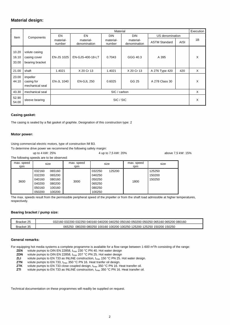
Material design:
Item Components
Material Execution
EN
material-number
EN
material-denomination
DIN
material-number
DIN
material-denomination
US denomination
1B ASTM Standard AISI
10.20
16.10
33.00
volute casing
casing cover
bearing bracket
EN-JS 1025 EN-GJS-400-18-LT 0.7043 GGG 40.3 A 395 X
21.00 shaft 1.4021 X 20 Cr 13 1.4021 X 20 Cr 13 A 276 Type 420 420 X
23.00
44.10
impeller
casing for
mechanical seal
EN-JL 1040 EN-GJL 250 0.6025 GG 25 A 278 Class 30 X
43.30 mechanical seal SIC / carbon X
52.90
54.00 sleeve bearing SIC / SIC X
Casing gasket:
The casing is sealed by a flat gasket of graphite. Designation of this construction type: 2
Motor power:
Using commercial electric motors, type of construction IM B3.
To determine drive power we recommend the following safety margin:
up to 4 kW: 25% 4 up to 7,5 kW: 20% above 7,5 kW: 15%
The following speeds are to be observed:
max. speed rpm
size max. speed
rpm size
max. speed rpm
size
3600
032160
032200
040160
040200
050160
050200
065160
065200
080160
080200
100160
100200
3000
032250
040250
050250
065250
080250
100250
125200
1800
125250
150200
150250
The max. speeds result from the permissible peripheral speed of the jmpeller or from the shaft load admissible at higher temperatures,
respectively.
Bearing bracket / pump size:
Bracket 25 032160 032200 032250 040160 040200 040250 050160 050200 050250 065160 065200 080160
Bracket 35 065250 080200 080250 100160 100200 100250 125200 125250 150200 150250
General remarks: For equipping hot media systems a complete programme is available for a flow range between 1-600 m3/h consisting of the range:
ZEN volute pumps to DIN EN 22858, tmax 230 °C PN 40. Hot water design
ZDN volute pumps to DIN EN 22858, tmax 207 °C PN 25. Hot water design
ZLI volute pumps to EN 733 as INLINE construction, tmax 150 °C PN 25. Hot water design.
ZTN volute pumps to EN 733, tmax 350 °C PN 16. Heat tranfer oil design.
ZTK volute pumps to EN 733 close coupled design, tmax 350 °C PN 16. Heat transfer oil.
ZTI volute pumps to EN 733 as INLINE construction, tmax 350 °C PN 16. Heat transfer oil.
Technical documentation on these programmes will readily be supplied on request.
3
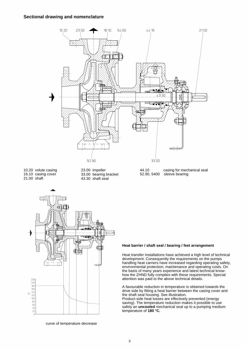
Sectional drawing and nomenclature
10.20 volute casing 16.10 casing cover 21.00 shaft
23.00 impeller 33.00 bearing bracket 43.30 shaft seal
44.10 casing for mechanical seal 52.90, 5400 sleeve bearing
curve of temperature decrease
Heat barrier / shaft seal / bearing / feet arrangement
Heat transfer installations have achieved a high level of technical development. Consequently the requirements on the pumps handling heat carriers have increased regarding operating safety, environmental protection, maintenance and operating costs. On the basis of many years experience and latest technical know-how the ZHND fully complies with these requirements. Special attention was paid to the above technical details. A favourable reduction in temperature is obtained towards the drive side by fitting a heat barrier between the casing cover and the shaft seal housing. See illustration. Product-side heat losses are effectively prevented (energy saving). The temperature reduction makes it possible to use safely an uncooled mechanical seal up to a pumping medium temperature of 180 °C.
4
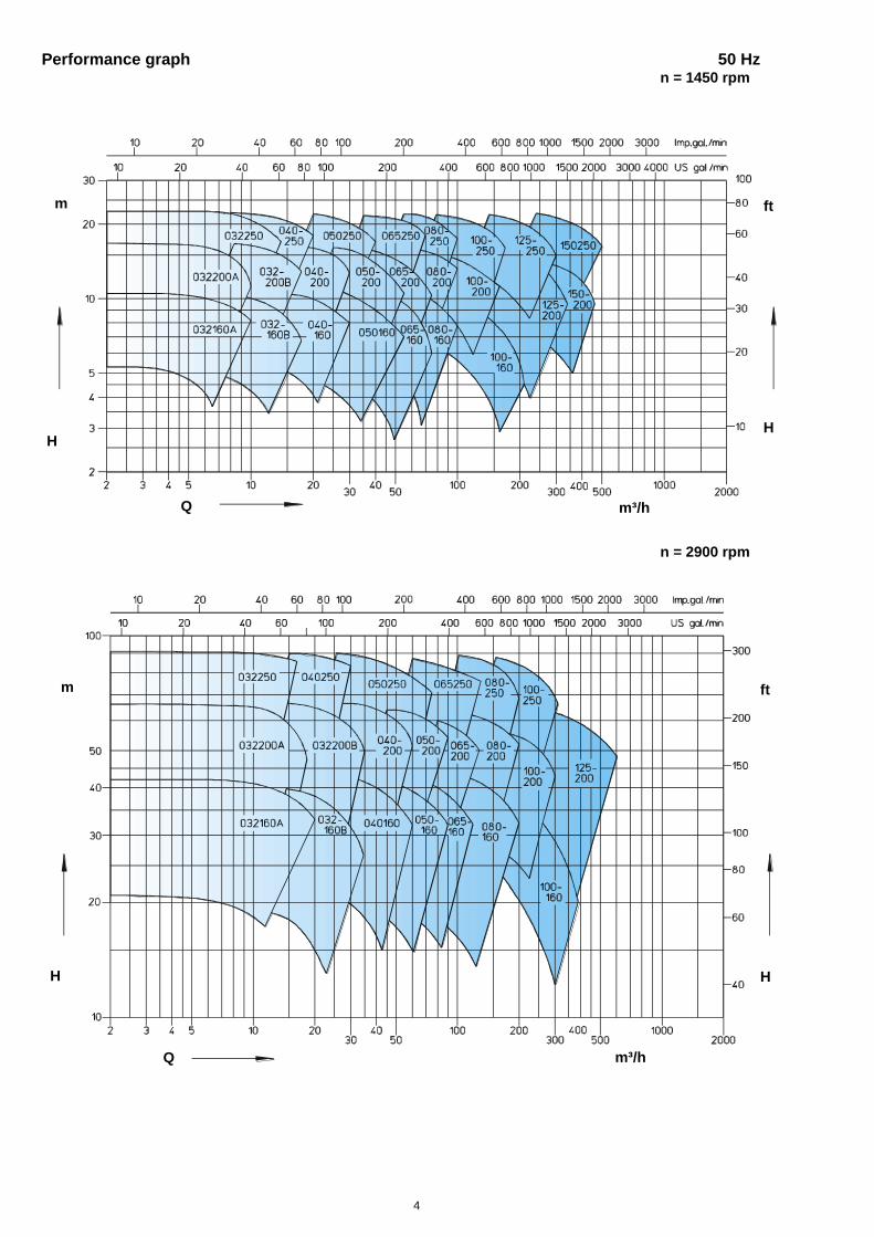
Performance graph 50 Hz n = 1450 rpm
n = 2900 rpm
H
H H
H
m ft
m³/h
m ft
m³/h Q
H
Q
H

5
Performance graph 60 Hz
n = 1750 rpm
n = 3500 rpm
H
H H
H
m³/h
m³/h
ft m
Q
m ft
Q
H
6
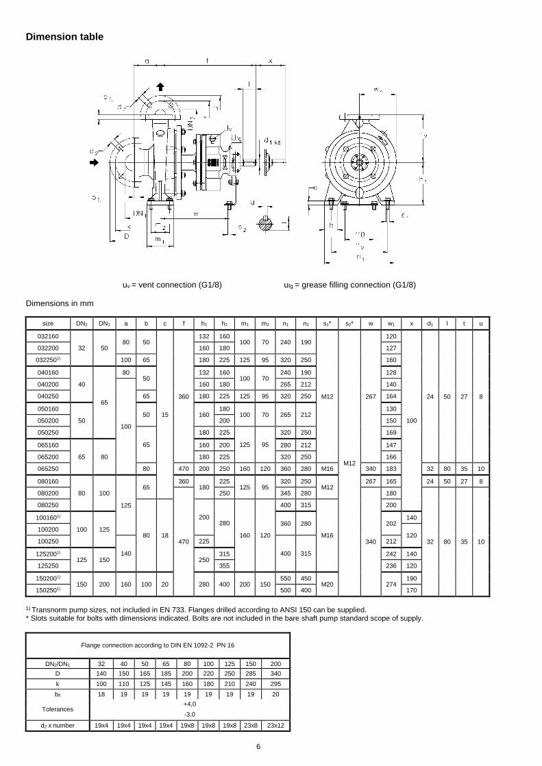
Dimension table
uv = vent connection (G1/8) ufg = grease filling connection (G1/8)
Dimensions in mm
size DN2 DN1 a b c f h1 h2 m1 m2 n1 n2 s1* s2* w w1 x d1 l t u
032160
32 50 80 50
15
360
132 160 100 70 240 190
M12
M12
267
120
100
24 50 27 8
032200 160 180 127
0322501) 100 65 180 225 125 95 320 250 160
040160
40
65
80 50
132 160 100 70
240 190 128
040200
100
160 180 265 212 140
040250 65 180 225 125 95 320 250 164
050160
50 50 160
180 100 70 265 212
130
050200 200 150
050250
65
180 225
125 95
320 250 169
065160
65 80
160 200 280 212 147
065200 180 225 320 250 166
065250 80 470 200 250 160 120 360 280 M16 340 183 32 80 35 10
080160
80 100
125
65 360
180 225
125 95 320 250
M12 267 165 24 50 27 8
080200
470
250 345 280
340
180
32 80 35 10
080250
80 18
200 280
160 120
400 315
M16
200
1001601)
100 125 360 280 202
140
100200 120
100250
140
225
400 315
212
1252001) 125 150 250
315 242 140
125250 355 236 120
1502001) 150 200 160 100 20 280 400 200 150
550 450 M20 274
190
1502501) 500 400 170
1) Transnorm pump sizes, not included in EN 733. Flanges drilled according to ANSI 150 can be supplied. * Slots suitable for bolts with dimensions indicated. Bolts are not included in the bare shaft pump standard scope of supply.
Flange connection according to DIN EN 1092-2 PN 16
DN2/DN1 32 40 50 65 80 100 125 150 200
D 140 150 165 185 200 220 250 285 340
k 100 110 125 145 160 180 210 240 295
bfl 18 19 19 19 19 19 19 19 20
Tolerances +4,0
-3,0
d2 x number 19x4 19x4 19x4 19x4 19x8 19x8 19x8 23x8 23x12

7
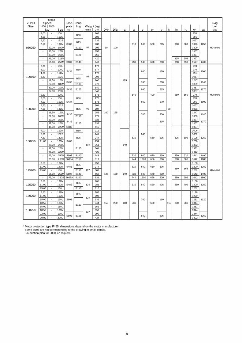
Foundation plan
Dimensions in mm
Motor ZHND Speed Base- Coup- Rag Size 1450 2900 plate ling Weight (kg) bolt
kW Size No. Pump Unit DN2 DN1 a b2 e1 e2 v f1 h3 h4 w* w1 size
0,37 - 71 S270
B68
78 360 420 320 115
682 650
0,55 1,10 80 81 716
- 1,50 90S
S301
89
390 480 350 125
197 357 774
730
M16x200
032160 - 2,20 90L 50 91 774
- 3,00 100L B80
101 815
- 4,00 112M 102 836
- 5,50 132S S342 B95
139 450 540 400 140
212 372
912 820 M20x400
- 7,50 132S 139 912
0,55 - 80 S270
B68
86 360 420 320 115
716 650
0,75 - 80 86 80 60 716
1,10 1,50 90S
S301
93
390 480 350 125
225 405 774
730
M16x200
1,50 2,20 90L 96 774
- 3,00 100L B80
106 32 50 815
032200 - 4,00 112M 55 107 836
- 5,50 132S S342
144 450 540 400 140
912 820
- 7,50 132S 144 912
- 11,00 160M S383
B95 163 490 600 440 160
240 420 1030 920
- 15,00 160M 163 1030
- 18,50 160L S344 191 450 660 400 180 1150 1020
0,75 - 80 107 736 M20x400
1,10 - 90S B68 110 794
1,50 - 90L 112 794
032250 2,20 - 100L S383
B80 56 123 100 490 600 440 160 75 260 485 835 920
- 7,50 132S 152 932
- 11,00 160M B95 171 1050
- 15,00 160M 171 1050
0,37 - 71
B68
72 682
0,55 - 80 S270 75 360 420 320 115 716 650
0,75 1,10 80 75 716
1,10 1,50 90S
S301
83
390 480 350 125
197 357 774
730
M16x200
040160 - 2,20 90L 44 85 80 774
- 3,00 100L B80 95 815
- 4,00 112M 97 836
- 5,50 132S S342
133 450 540 400 140
212 372
912 820
- 7,50 132S B95 143 912 M20x400
- 11,00 160M S383 164 40 65 490 600 440 160 60 240 400 1030 920
0,55 - 80
B68
81 736
0,75 - 80 81 736
1,10 - 90S S301 84 390 480 350 125 225 405 794 730 M16x200
1,50 - 90L 86 794
040200 - 3,00 100L B80
46 97 100 835
- 4,00 112M 98 856
- 5,50 132S S342
B95
135 450 540 400 140
240 420
932 820
M20x400 - 7,50 132S 135 932
- 11,00 160M S383
161 490 600 440 160
1050 920
- 15,00 160M 161 1050
min. length of rag bolts

8
Motor ZHND Speed Base- Coup- Rag Size 1450 2900 plate ling Weight (kg) bolt
kW Size No. Pump Unit DN2 DN1 a b2 e1 e2 v f1 h3 h4 w* w1 size
1,10 - 90S B68
112 794
1,50 - 90L 114 794
2,20 - 100L B80
125 835
040250 3,00 - 100L S383 58 125 40 490 600 440 160 75 260 485 835 920 M20x400
- 7,50 132S
B95
154 932
- 11,00 160M 173 1050
- 15,00 160M 173 1050
- 18,50 160L S434 217 540 660 490 170 1112 1000
0,55 - 80
B68
84 736
0,75 - 80 84 736
1,10 - 90S S301 87 390 480 350 125 225 405 794 730 M16x200
- 2,20 90L 89 794
050160 - 3,00 100L B80
48 99 835
- 4,00 112M 100 856
- 5,50 132S S342
137 450 540 400 140
932 820
- 7,50 132S B95 137 240 420 932 M20x400
- 11,00 160M S383 163 490 600 440 160 1050 920
0,75 - 80 82 65 60 736
1,10 - 90S B68 85 794
1,50 - 90L S301 87 390 480 350 125 225 425 794 730 M16x200
2,20 3,00 100L B80
98 50 835
050200 4,00 112M 46 98 856
5,50 132S S342
135 450 540 400 140
932 820
- 7,50 132S 135 932
- 11,00 160M S383
B95 161 490 600 440 160
240 440 1050 920
- 15,00 160M 161 1050
- 18,50 160L S344 166 450 660 400 180 1112 1020
1,50 - 90L B68 114 794
2,20 - 100L 125 835
3,00 - 100L S383 B80 125 490 600 440 160 835 920
4,00 - 112M 126 260 485 856
050250 - 11,00 160M 58 173 100 75 1050
- 15,00 160M B95 173 1050
- 18,50 160L S434
217 660
170
1112 1000
- 22,00 180M B110 230 540 490 1174
- 30,00 200L S435 B125 297 740 200 280 505 1232 1140
0,75 - 80 98 736
1,10 - 90S B68 101 794
1,50 - 90L S342 103 450 540 400 140 794 820
065160 2,20 - 100L B80 54 113 60 240 440 835
- 5,50 132S
B95
143 932
- 7,50 132S 143 932 M20x400
- 11,00 160M 169 1050
- 15,00 160M 169 1050
1,10 - 90S B68
117 794
1,50 - 90L 119 794
2,20 - 100L S383 130 490 600 440 160 835 920
3,00 - 100L B80 130 835
065200 4,00 - 112M 63 131 75 260 485 856
- 11,00 160M 178 65 80 1050
- 15,00 160M B95 178 1050
- 18,50 160L S434
222 660
170
1112 1000
- 22,00 180M B110 235 1174
- 30,00 200L S435 B125 302 740 200 505 1232 1140
2,20 - 100L
S434
173
660
170
945
1000
3,00 - 100L B80 173 945
4,00 - 112M 174 540 490 966
5,50 - 132S B95
202 280 530 1042
065250 - 18,50 160L S435
90 256 740
200
90 1222 1140
- 22,00 180M B110 269 1284
- 30,00 200L S436
336 215
1342 1270
- 37,00 200L B125 336 840 1342
- 45,00 225M S486 413 610 550 205 325 575 1372 1250 M24x400
0,75 - 80 106 761
1,10 - 90S B68 109 819
1,50 - 90L 111 819
2,20 - 100L S383 B80 122 490 600 440 160 860 920
080160 3,00 - 100L 55 122 485 860
- 7,50 132S
B95
151 957
- 11,00 160M 170 1075
- 15,00 160M 170 1075
- 18,50 160L S434
214 540 660 490 170
260 1137 1000
- 22,00 180M B110 227 80 100 125 75 1199 M20x400
1,50 - 90L
S383
B80
148
490 600 440 160
929
920
2,20 - 100L 158 970
3,00 - 100L 158 970
4,00 - 112M 159 510 991
080200 5,50 - 132S S434
91 203 660 170
1067 1000
- 15,00 160M B95 222 1185
- 18,50 160L S435
257 540 740 490 200
1247 1140
- 22,00 180M B110 270 1309
- 30,00 200L S436 B125
337 840 215
280 530 1367
1270
- 37,00 200L 337 1367
9
Motor ZHND Speed Base- Coup- Rag Size 1450 2900 plate ling Weight (kg) bolt
kW Size No. Pump Unit DN2 DN1 a b2 e1 e2 v f1 h3 h4 w* w1 size
3,00 - 100L B80 205 970
4,00 - 112M 206 991
5,50 - 132S B95 235 1067
7,50 - 132M S486 238 610 840 550 205 300 580 1093 1250
080250 - 22,00 180M B110 97 295 80 100 1309 M24x400
- 30,00 200L 355 1367
- 37,00 200L B125 355 1367
- 45,00 225M 420 325 605 1397
- 55,00 250M S607 B140 642 730 940 670 230 350 630 1527 1400
2,20 - 100L
S434
177
660
170
970
1000
3,00 - 100L B80 177 970
4,00 - 112M 178 991
100160 5,50 - 132S B95
94 206 1067
- 18,50 160L S435
260 125 740
200
1247 1140
- 22,00 180M B110 273 1309
- 30,00 200L S436 B125
340 840
215
1367 1270
- 37,00 200L 340 1367
2,20 - 100L 175 540 490 280 560 970 M20x400
3,00 - 100L B80 175 970
4,00 - 112M S434 176 660 170 991 1000
5,50 - 132S 204 1067
100200 7,50 - 132M B95 92 207 90 1093
- 18,50 160L S435
258 100 125 740
200
1247 1140
- 22,00 180M B110 271 1309
- 30,00 200L S436
338 215
1367 1270
- 37,00 200L B125 338 1367
- 45,00 225M S486 415 1397
4,00 - 112M B80 212 1006
5,50 - 132S 241 840 1082
7,50 - 132M B95 244 610 550 205 325 605 1108 1250
100250 11,00 - 160M S486 259 1200
- 30,00 200L 103 361 140 1382
- 37,00 200L B125 361 1382
- 45,00 225M 426 1412
- 55,00 250M S607 B140 648 730 940 670 230 350 630 1542 1400
- 75,00 280S S609A B160 917 744 1200 696 300 380 660 1642 1800
7,50 - 132M B95
258
350 665
1108
11,00 - 160M S486 274 610 840 550 205 1200 1250
125200 15,00 - 160L B110 117 303 1262 M24x400
- 55,00 250M S607 B140 662 125 150 140 730 940 670 230 1542 1400
- 75,00 280S S609A B160 931 744 1200 696 300 380 695 1642 1800
7,50 - 132M B95
265 1108
125250 11,00 - 160M S486 124 281 610 840 550 205 350 705 1200 1250
15,00 - 160L B110 310 1262
7,50 - 132M B95
128
286 1128
150200 11,00 - 160M 302 1220
15,00 - 160L S605
B110
332 740 190 1282 1120
18,50 - 180M 344 150 200 160 730 670 110 380 780 1344
15,00 - 160L
147
351 1282
150250 18,50 - 180M 353 1344
22,00 - 180L S606 B125
390 840
205
1344 1250
30,00 - 200L 434 1402
* Motor protection type IP 55, dimensions depend on the motor manufacturer. Some sizes are not corresponding to the drawing in small details. Foundation plan for 60Hz on request.
10
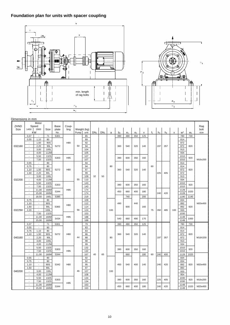
Foundation plan for units with spacer coupling
Dimensions in mm
Motor ZHND Speed Base Coup- Rag Size 1450 2900 Size plate ling Weight (kg) bolt
KW No. Pump unit DN2 DN1 a b2 e1 e2 v f1 h3 h4 x w* w1 size
0,37 - 71 S301 85 390 480 350 125 780 730
0,55 1,10 80 89 814
- 1,50 90S H80 92 872
032160 - 2,20 90L S272 50 94 360 540 320 140 197 357 872 820
- 3,00 100L 104 913
- 4,00 112M 105 934
- 5,50 132S S303 H95
107 390 600 350 160
1010 920
- 7,50 132S 107 1010 M16x200
0,55 - 80 94 814
0,75 - 80 94 80 60 814
1,10 1,50 90S S272 H80 97 360 540 320 140 872 820
1,50 2,20 90L 99 225 405 872
- 3,00 100L 109 32 50 913
032200 - 4,00 112M 55 110 934
- 5,50 132S S303
143 390 600 350 160
1010 920
- 7,50 132S 143 1010
- 11,00 160M S344
H95 174 450 660 400 180
1128 1020
- 15,00 160M 174 240 420 1128
- 18,50 160L S385 219 740 200 1190 1140
0,75 - 80
H80
109 834
1,10 - 90S 112 490 440 892 M20x400
1,50 - 90L S383 114 600 160 892 920
032250 2,20 - 100L 56 124 100 75 260 485 100 933
- 7,50 132S 153 1030
- 11,00 160M S434
H95 188 540 660 490 170
1148 1000
- 15,00 160M 188 1148
0,37 - 71 S301 79 390 480 350 125 780 730
0,55 - 80 83 814
0,75 1,10 80 83 814
1,10 1,50 90S S272 H80 86 360 540 320 140 872 820
040160 - 2,20 90L 44 88 80 197 357 872 M16X200
- 3,00 100L 98 913
- 4,00 112M 99 934
- 5,50 132S S303
132 390 600 350 160
1010 920
- 7,50 132S H95 132 1010
- 11,00 160M S344 167 40 65 660 180 60 240 400 1128 1020
0,55 - 80 92 834
0,75 - 80 92 834
1,10 - 90S S342 H80 95 450 540 400 140 240 420 892 820 M20x400
1,50 - 90L 97 892
040200 - 3,00 100L 46 107 100 933
- 4,00 112M 108 954
- 5,50 132S S303
H95
134 390 600 350 160
225 405
1030 920 M16x200
- 7,50 132S 134 1030
- 11,00 160M S344
163 450 660 400 180
240 420
1148 1020 M20x400
- 15,00 160M 163 1148
min. length of rag bolts
11
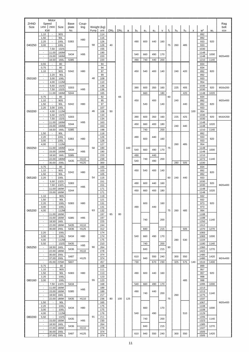
Motor ZHND Speed Base Coup- Rag Size 1450 2900 Size plate ling Weight (kg) bolt
KW No. Pump unit DN2 DN1 a b2 e1 e2 v f1 h3 h4 x w* w1 size
1,10 - 90S
H80
114 892
1,50 - 90L 116 892
2,20 - 100L S383 126 490 600 440 160 933 920
040250 3,00 - 100L 58 126 40 75 260 485 933
- 7,50 132S
H95
155 1030
- 11,00 160M S434
190 540 660 490 170
1148 1000
- 15,00 160M 220 1148 M20x400
- 18,50 160L S385 220 490 740 440 200 1210 1140
0,55 - 80 94 834
0,75 - 80 94 834
1,10 - 90S S342 H80 97 450 540 400 140 240 420 892 820
- 2,20 90L 99 892
050160 - 3,00 100L 48 109 933
- 4,00 112M 110 954
- 5,50 132S S303
136 390 600 350 160
225 405
1030 920 M16x200
- 7,50 132S H95 136 1030
- 11,00 160M S344 165 660 180 420 1148 1020
0,75 - 80 92 65 60 834
1,10 - 90S 95 450 400 240 892 M20x400
1,50 - 90L S342 H80 97 540 140 440 892 820
2,20 3,00 100L 107 933
050200 - 4,00 112M 46 108 50 100 954
- 5,50 132S S303
134 390 600 350 160
225 425
1030 920 M16X200
- 7,50 132S 134 1030
- 11,00 160M S344
H95 163 450 660 400 180
1148 1020
- 15,00 160M 163 240 440 1148
- 18,50 160L S385 198 740 200 1210 1140
1,50 - 90L
S383 H80
116
600
160
892
920
2,20 - 100L 126 490 440 933
3,00 - 100L 126 933
4,00 - 112M 127 260 485 954
050250 - 11,00 160M S434
58 190 100 540 660 490 170
75 1148 1000
- 15,00 160M H95 190 1148
- 18,50 160L S385 220 490 440 1210
- 22,00 180M S435
H110 239 540
740 490
200 1272 1140
- 30,00 200L H125 300 280 505 1330
0,75 - 80
S342 H80
100 834
820
1,10 - 90S 103 450 540 400 140 892
1,50 - 90L 105 892
065160 2,20 - 100L 54 115 60 240 440 933
- 5,50 132S S383
H95
151 490 600 440 160
1030 920
- 7,50 132S 151 1030 M20x400
- 11,00 160M S344
171 450 660 400 180
1148 1020
- 15,00 160M 171 1148
1,10 - 90S 119 932
1,50 - 90L 121 932
2,20 - 100L S383 H80 131 600 160 973 920
3,00 - 100L 131 490 440 973
065200 4,00 - 112M 63 132 75 260 485 994
- 11,00 160M 197 65 80
740
200
1188
1140
- 15,00 160M S385 H95 197 1188
- 18,50 160L 225 1250
- 22,00 180M S435 H110 244 1312
- 30,00 200L S436 H125 312 840 215 505 1370 1270
2,20 - 100L 174 1083
3,00 - 100L S434 H80 174 540 660 490 170 1083 1000
4,00 - 112M 175 280 530 1104
5,50 - 132S S435 H95
210 740 200 1180 1140
065250 - 18,50 160L S436
90 264 840
215
90 1360 1270
- 22,00 180M H110 278 1422
- 30,00 200L S487
374 610
550 240
300 550
1480 1420
- 37,00 200L H125 374 940 1480 M24x400
- 45,00 225M S607 457 730 670 230 325 575 140 1510 1400
0,75 - 80 108 899
1,10 - 90S 111 957
1,50 - 90L S383 H80 113 490 600 440 160 957 920
2,20 - 100L 123 998
080160 3,00 - 100L 55 123 485 998
- 7,50 132S S434
H95
168 540 660 490 170 1095 1000
- 11,00 160M 189
740
200
1213
1140
- 15,00 160M S385 189 490 440 1213
- 18,50 160L 217 260 1275
- 22,00 180M S435 H110 236 80 100 125 75 1337
1,50 - 90L
S434 H80
165
660
170
1067
1000
M20x400
2,20 - 100L 175 1108
3,00 - 100L 175 1108
4,00 - 112M 176 540 490 510 1129
080200 5,50 - 132S S435
91 211 740
200
1205 1140
- 15,00 160M H95 230 1323
- 18,50 160L S436
264 840
215
1385 1270
- 22,00 180M H110 278 1447
- 30,00 200L S487 H125
374 610 940 550 240
300 550
1505 1420
- 37,00 200L 374 1505
12
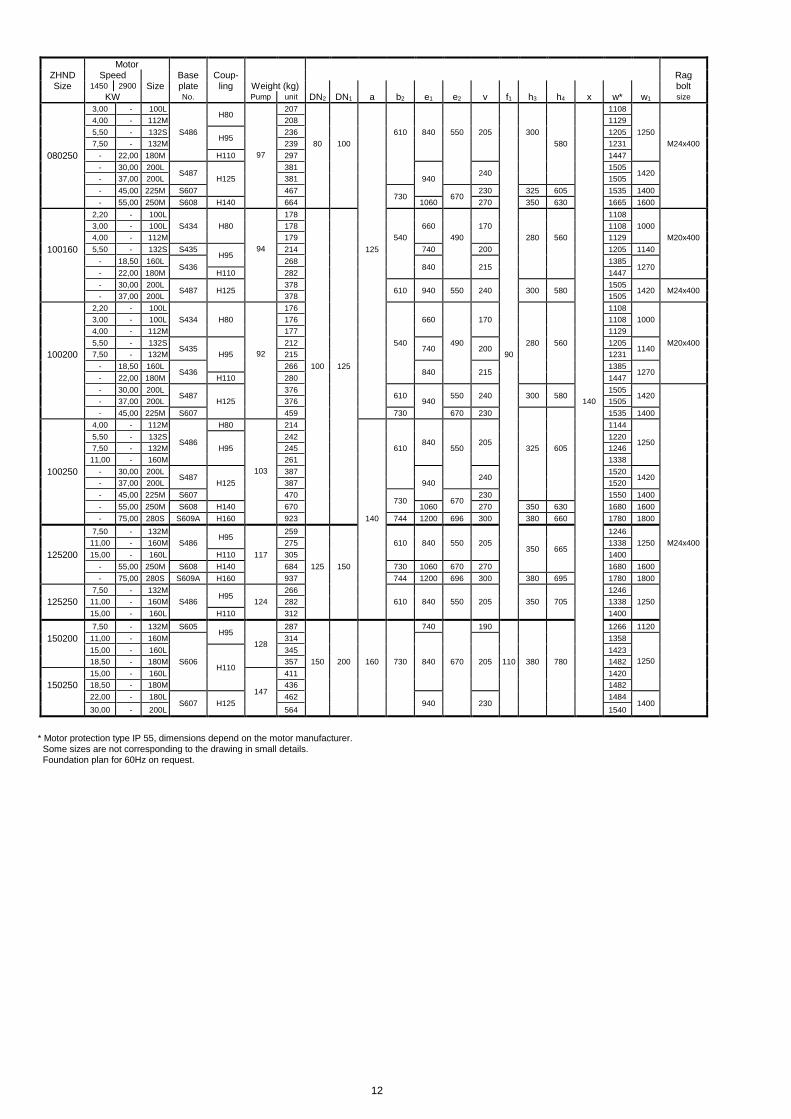
Motor ZHND Speed Base Coup- Rag Size 1450 2900 Size plate ling Weight (kg) bolt
KW No. Pump unit DN2 DN1 a b2 e1 e2 v f1 h3 h4 x w* w1 size
3,00 - 100L H80
207 1108
4,00 - 112M 208 1129
5,50 - 132S S486 H95
236 610 840 550 205 300 1205 1250
7,50 - 132M 239 80 100 580 1231 M24x400
080250 - 22,00 180M H110 97 297 1447
- 30,00 200L S487
381 240
1505 1420
- 37,00 200L H125 381 940 1505
- 45,00 225M S607 467 730
670
230 325 605 1535 1400
- 55,00 250M S608 H140 664 1060 270 350 630 1665 1600
2,20 - 100L 178 1108
3,00 - 100L S434 H80 178 660 170 1108 1000
4,00 - 112M 179 540 490 280 560 1129 M20x400
100160 5,50 - 132S S435 H95
94 214 125 740 200 1205 1140
- 18,50 160L S436
268 840
215
1385 1270
- 22,00 180M H110 282 1447
- 30,00 200L S487 H125
378 610 940 550 240
300 580
1505 1420 M24x400
- 37,00 200L 378 1505
2,20 - 100L 176 1108
3,00 - 100L S434 H80 176 660 170 1108 1000
4,00 - 112M 177 1129
5,50 - 132S S435
212 540 740
490 200
280 560 1205 1140
M20x400
100200 7,50 - 132M H95 92 215 90 1231
- 18,50 160L S436
266 100 125 840
215
1385 1270
- 22,00 180M H110 280 1447
- 30,00 200L S487
376 610
550 240
300 580
1505 1420
- 37,00 200L H125 376 940 140 1505
- 45,00 225M S607 459 730 670 230 1535 1400
4,00 - 112M
S486
H80 214
840
205
1144
1250
5,50 - 132S 242 1220
7,50 - 132M H95 245 610 550 325 605 1246
11,00 - 160M 261 1338
100250 - 30,00 200L S487
103 387 240
1520 1420
- 37,00 200L H125 387 940 1520
- 45,00 225M S607 470 730
670
230 1550 1400
- 55,00 250M S608 H140 670 1060 270 350 630 1680 1600
- 75,00 280S S609A H160 923 140 744 1200 696 300 380 660 1780 1800
7,50 - 132M H95
259
350 665
1246
11,00 - 160M S486 275 610 840 550 205 1338 1250 M24x400
125200 15,00 - 160L H110 117 305 1400
- 55,00 250M S608 H140 684 125 150 730 1060 670 270 1680 1600
- 75,00 280S S609A H160 937 744 1200 696 300 380 695 1780 1800
7,50 - 132M H95
266 1246
125250 11,00 - 160M S486 124 282 610 840 550 205 350 705 1338 1250
15,00 - 160L H110 312 1400
7,50 - 132M S605 H95
128
287 740 190 1266 1120
150200 11,00 - 160M 314 1358
15,00 - 160L
H110
345 1423
18,50 - 180M S606 357 150 200 160 730 840 670 205 110 380 780 1482 1250
15,00 - 160L
147
411 1420
150250 18,50 - 180M 436 1482
22,00 - 180L S607 H125
462 940
230
1484 1400
30,00 - 200L 564 1540
* Motor protection type IP 55, dimensions depend on the motor manufacturer. Some sizes are not corresponding to the drawing in small details. Foundation plan for 60Hz on request.

13
Data regarding pump size
Any changes in the interest of the technical development are reserved.
Type + Pump size Hydraulic + Bearing Shaft sealing Material desing Casing gasket
A hydraulic 1
B hydraulic 2 2 confined flat
A grease lubricated reinforced BJ3 unbalanced standard 1B main parts of gasket of
antifriction bearing and one internal mechanical seal spheroidal cast iron graphite with
liquid flushed sleeve bearing A4 insertion
032160 AA
032160 BA
032200 AA
032200 BA
032250
040160
040200
040250
050160
050200
050250
ZHND 065160 BJ3 1B 2
065200
065250
080160 AA
080200
080250
100160
100200
100250
125200
125250
150200
150250

14
Sterling SIHI (Spain), S.L. Vereda de los Zapateros s/n, Pozuelo de Alarcón 28223 Madrid, Spain. Telephone +34 91 709 1310 Telefax +34 91 715 9700
www.sihi.com