VOLUNTARY SERVICE CAMPAIGN 2010 QX56 INTELLIGENT …
13
1/13 Reference: Date: ITB10-003 January 28, 2010 VOLUNTARY SERVICE CAMPAIGN 2010 QX56 INTELLIGENT CRUISE CONTROL (ICC) SENSOR CAMPAIGN ID #: PC028 APPLIED VEHICLES: 2010 QX56 (JA60) Check Service Comm to confirm campaign eligibility INTRODUCTION Infiniti is conducting a Voluntary Service Campaign on certain MY 2010 QX56 vehicles for the Intelligent Cruise Control. On some of the affected vehicles, the system may incorrectly identify vehicles in adjacent lanes as being in the path of the QX56. To remedy this, Infiniti will inspect the Intelligent Cruise Control and reposition the sensor if necessary. IDENTIFICATION NUMBER Infiniti has assigned identification number PC028 to this campaign. This number must appear on all communications and documentation of any nature dealing with this campaign. DEALER RESPONSIBILITY Dealers are to correct each vehicle falling within the range of this campaign that enters the service department. This includes vehicles purchased from private parties or presented by transient (tourist) owners and vehicles in a dealer’s inventory.
Transcript of VOLUNTARY SERVICE CAMPAIGN 2010 QX56 INTELLIGENT …
1/13
Reference: Date:
ITB10-003 January 28, 2010
VOLUNTARY SERVICE CAMPAIGN 2010 QX56 INTELLIGENT CRUISE CONTROL (ICC) SENSOR
CAMPAIGN ID #: PC028
APPLIED VEHICLES: 2010 QX56 (JA60)
Check Service Comm to confirm campaign eligibility
INTRODUCTION Infiniti is conducting a Voluntary Service Campaign on certain MY 2010 QX56 vehicles for the Intelligent Cruise Control. On some of the affected vehicles, the system may incorrectly identify vehicles in adjacent lanes as being in the path of the QX56. To remedy this, Infiniti will inspect the Intelligent Cruise Control and reposition the sensor if necessary. IDENTIFICATION NUMBER
Infiniti has assigned identification number PC028 to this campaign. This number must appear on all communications and documentation of any nature dealing with this campaign.
DEALER RESPONSIBILITY
Dealers are to correct each vehicle falling within the range of this campaign that enters the service department. This includes vehicles purchased from private parties or presented by transient (tourist) owners and vehicles in a dealer’s inventory.

SERVICE PROCEDURE
WARNING: Do not look straight into the ICC sensor (laser beam discharge) when performing “Laser Beam Aiming Adjustment”. NOTE:
• Do not use the “laser pointer” attached to the target board support to align the target board position.
• Once “LASER BEAM ADJUST” mode is entered with CONSULT-III, the procedure must be completed or the ICC system will not function.
Vehicle Set-Up
1. Prepare the vehicle for “Laser Beam Aiming Adjustment:”
• Fuel Tank is approximately full.
• Place the vehicle on a flat level surface.
• Make sure you leave a minimum of 5.5 meters (18 feet) of space in front of the vehicle.
• Check/adjust tire pressure to the specified pressure (see Tire and Loading Information label).
• Make sure there is “no-load” in the vehicle other than the driver (or equivalent weight placed in the driver's position).
• Coolant and engine oil must be filled up to the correct level.
• Shift the gear selector into “P” position and release the parking brake.
• Clean the ICC sensor with a soft cloth.
2/13 ITB10-003

Target Board Set-Up
2. Obtain a length of string about 9 meters (30 feet) long. 3. Tape one end of the string to the ground at the center-point of the rear of the vehicle (see Figure 1).
a. Use the “Infiniti” emblem to align a plumb-bob. b. Use the plumb-bob to mark the center point on the ground. c. Tape the string to the ground at the center point.
Use emblem for centering
Tape string to ground
Plumb-bob
Figure 1
3/13 ITB10-003
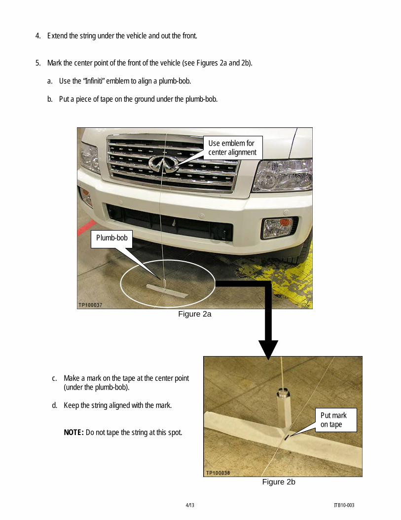
4. Extend the string under the vehicle and out the front. 5. Mark the center point of the front of the vehicle (see Figures 2a and 2b).
a. Use the “Infiniti” emblem to align a plumb-bob. b. Put a piece of tape on the ground under the plumb-bob.
Use emblem for center alignment
Figure 2a
Figure 2b
c. Make a mark on the tape at the center point (under the plumb-bob).
d. Keep the string aligned with the mark.
NOTE: Do not tape the string at this spot.
Plumb-bob
Put mark on tape
4/13 ITB10-003

Tape end of string to the ground.
18 Feet(5.5 meters)
TP020467
Use Infiniti emblemto align string withcenterline of vehicle.
Figure 3
6. Pull the string out about 5.5 meters (18 feet) in front
of the vehicle (see Figure 3). 7. Pull the string straight and align it with the centerline
of the vehicle front, then tape the string to the ground.
NOTE: Keep the string aligned with the center point mark you made in step 5.
Measure tape
Plumb-bob
8. M
v 9. P
easure 5 meters (16 feet 4¾ inch) in front of the ehicle (from the plumb-bob).
lace a piece of tape on the ground and mark the 5 meter (16 feet 4¾ inch) point (see Figures 4a and 4b).
Figure 4a Figure 4b
(5 meters / 16 feet 4¾ inch)
5/13 ITB10-003

10. Attach the target board to the support base and adjust it to 0 degrees (straight across). 11. Place the target board face at the 5 meter (16 feet
4¾ inch) point as shown in Figure 5.
• This is the tape and mark you made in step 9.
Figure 5
400 390 380 370 360 350 340 330 320 310 300 290 280 270 260 250 240 230 220 210 200 190 180 170 160
15 14 13 12 11 10 9 8 7 6
TP020469
400 390 380 370 360 350 340 330 320 310 300 290 280 270 260 240 230 220 210 200 190 180 170 160
15 14 13 12 11 10 9 8 7 6
250
Align string with scale in correct location.
As shown, string is aligned at 10 inches(254 mm) for QX4.
250
Front of vehicle
10 inch mark
Target BoardSupport Base
String
218 mm
String
(5 meters / 16' 4¾"
12. Align the support base to the string as follows:
NOTE: The support base has an alignment scale on both sides, driver and passenger. Use the driver side.
a. Make sure the support base leg is aligned
(parallel) with the string. b. Move the base left or right and align the string to
the 218 mm (8 9/16 inch) reading on the scale.
NOTE: Make sure the leg of the support base is always parallel to the string.
Figure 6
6/13 ITB10-003

13. Level the support base (see Figure 6).
• Bring the bubble into the center of the level indicator by turning the knobs on the support base legs.
NOTE: If the work surface under the support base is slightly uneven, use the center adjustment for additional leveling.
Level indicator
Center adjustment
Figure 7 14. Adjust the target board height.
• Set the top of the target board to 938 mm (36 15/16 inch) from the ground.
Figure 8 15. Angle the target board toward the driver side and set it to 20 degrees.
Figure 9
7/13
Leveling knobs
938 mm
ITB10-003
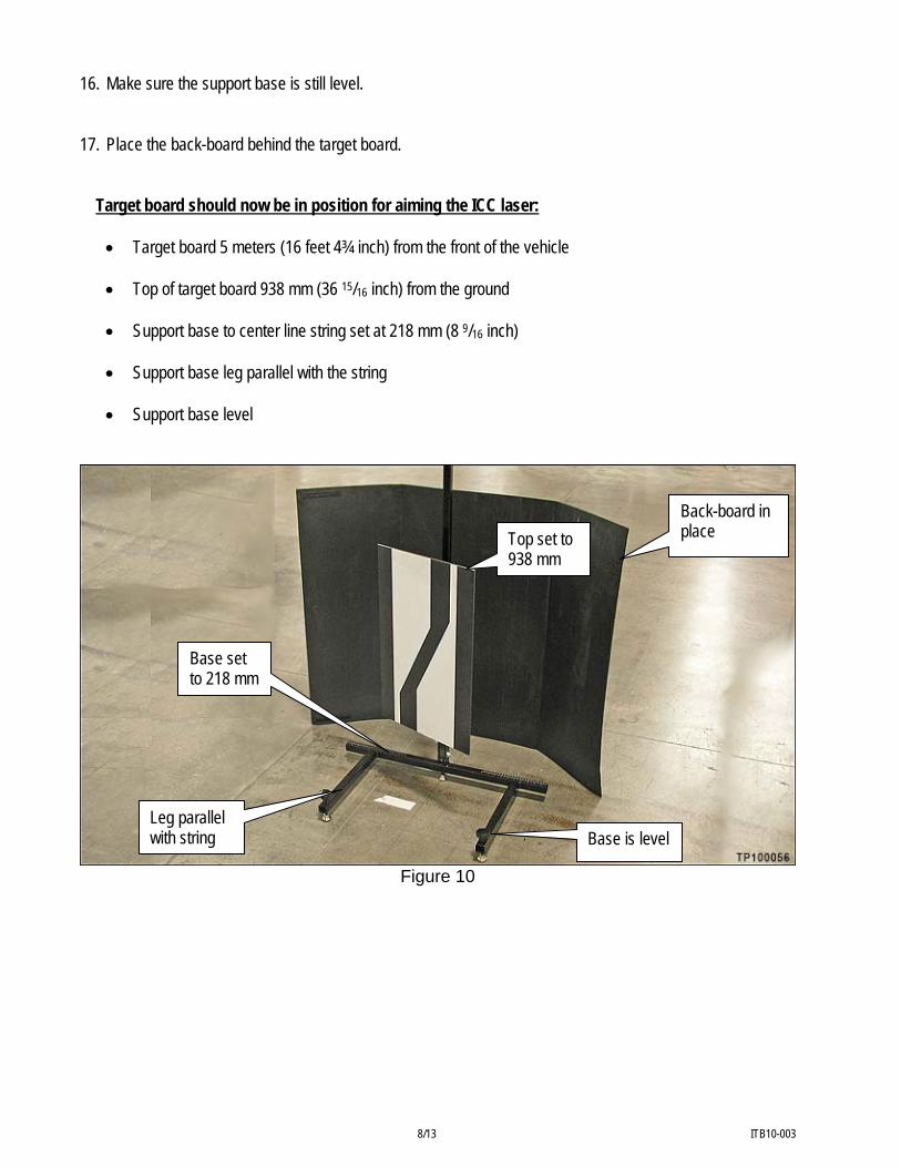
16. Make sure the support base is still level. 17. Place the back-board behind the target board. Target board should now be in position for aiming the ICC laser:
• Target board 5 meters (16 feet 4¾ inch) from the front of the vehicle
• Top of target board 938 mm (36 15/16 inch) from the ground
• Support base to center line string set at 218 mm (8 9/16 inch)
• Support base leg parallel with the string
• Support base level
Back-board in place Top set to
938 mm
Base set to 218 mm
Leg parallel with string Base is level
Figure 10
8/13 ITB10-003

ICC Aiming 18. Connect C-III to the vehicle. 19. Start the engine and let it idle. 20. Perform “Standard Height Level” with C-III.
a. Navigate C-III to: System Diagnosis > AIR LEVELIZER > Work Support > Standard Height Level
b. Select NEXT and START; wait for “completed” to display. 21. Navigate C-III to: System Diagnosis > ICC/ADAS > Work Support > LASER BEAM ADJUST
NOTE: Once “LASER BEAM ADJUST” mode is entered with C-III, the procedure must be completed or the ICC system will not function.
22. Select START.
NOTE: If the ICC sensor adjustment screen (ADJUST THE VERTICAL OF LASER BEAM AIMING) does not appear on the C-III screen 10 seconds after touching START, the following may be the cause:
• Target Board is not set accurately.
• There is not enough space beside the Target Board.
• Sensor may be installed out of the adjustable range (vehicle body may be damaged due to collision or sensor is installed incorrectly).
• The area is not suitable for the adjustment work.
• ICC sensor is not clean.
23. After C-III displays “ADJUST THE VERTICAL OF LASER BEAM AIMING”:
• Use the vertical adjusting screw to adjust the
“U/D CORRECT” value.
• Spec is 0 with a range of ±4.
• See adjustment notes on the next page. Figure 11
9/13 ITB10-003
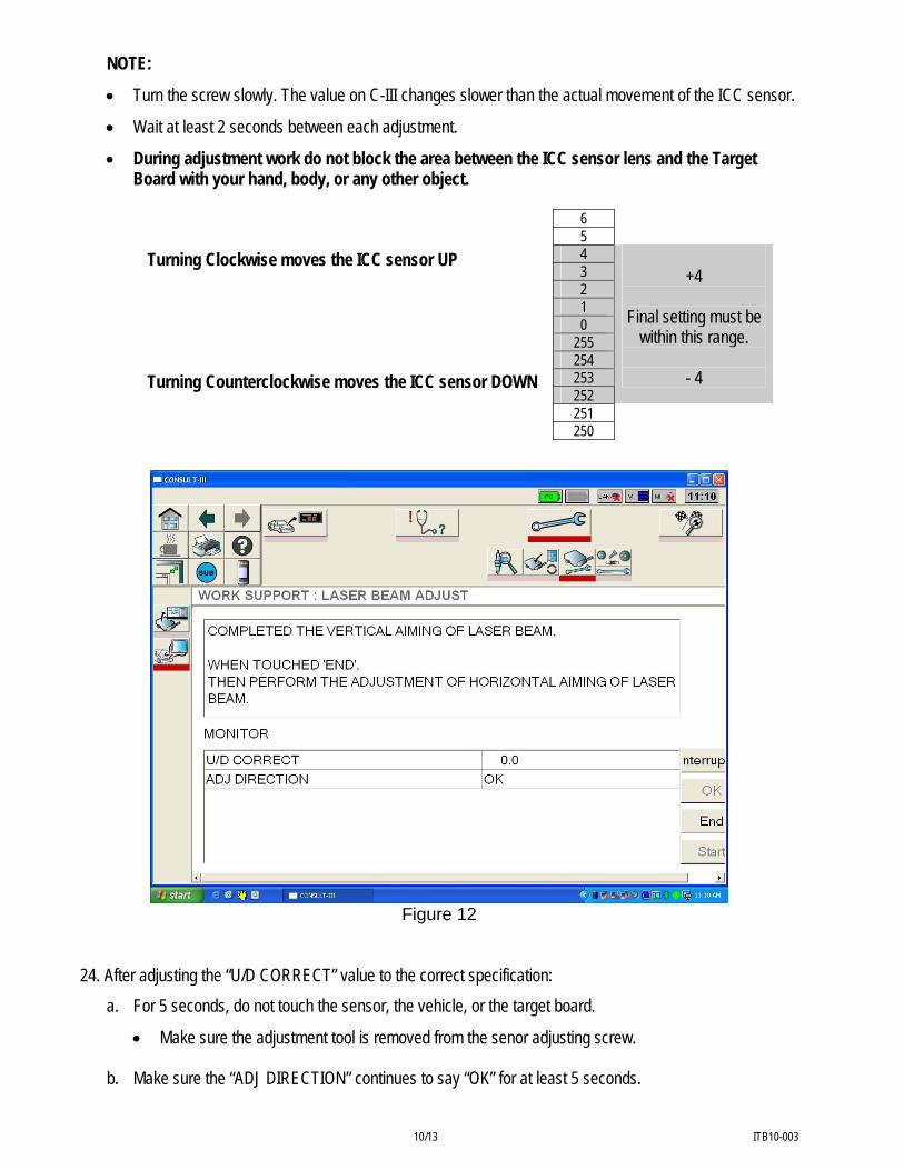
NOTE:
• Turn the screw slowly. The value on C-III changes slower than the actual movement of the ICC sensor.
• Wait at least 2 seconds between each adjustment.
• During adjustment work do not block the area between the ICC sensor lens and the Target Board with your hand, body, or any other object.
Turning Clockwise moves the ICC sensor UP Turning Counterclockwise moves the ICC sensor DOWN
6 5 4 3 2 1 0
255 254 253 252
+4
Final setting must be
within this range.
- 4
251 250
Figure 12
24. After adjusting the “U/D CORRECT” value to the correct specification:
a. For 5 seconds, do not touch the sensor, the vehicle, or the target board.
• Make sure the adjustment tool is removed from the senor adjusting screw.
b. Make sure the “ADJ DIRECTION” continues to say “OK” for at least 5 seconds.
10/13 ITB10-003

25. With “COMPLETED THE VERTICAL AIMING OF LASER BEAM” displayed on the screen, touch “END”. 26. “ADJUSTING AUTOMATIC HORIZONTAL LASER BEAM AIMING” should now display - wait while the
horizontal adjustment is made automatically (maximum: 10 seconds). 27. When automatic horizontal adjustment is complete, “Normally Completed” will display.
Figure 13
28. Procedure end – close C-III.
11/13 ITB10-003

CLAIMS INFORMATION
Submit a “CM” line claim using the following claims coding:
“CM” I.D.: PC028
DESCRIPTION OP CODE FRT Adjust ICC Sensor PC0280 0.3 hrs
12/13 ITB10-003

OWNER’S LETTER
Dear Infiniti QX56 Owner: Infiniti is committed to providing the highest levels of product safety, quality and customer satisfaction. With that in mind, we want to bring to your attention important information about the Intelligent Cruise Control in your QX56. REASON FOR CAMPAIGN Your QX56 is equipped with Intelligent Cruise Control. On some model year 2010 QX56 vehicles, the Intelligent Cruise Control sensor may, in certain situations, incorrectly identify vehicles in adjacent lanes as being in the path of your vehicle. WHAT INFINITI WILL DO To assure your continued satisfaction and confidence in your QX56, Infiniti will inspect the Intelligent Cruise Control Sensor in your vehicle and align the sensor. This service, free for parts and labor, should take about one hour to complete, but your Infiniti retailer may require your vehicle for a longer period of time based upon their work schedule. Please contact your Infiniti retailer to perform this important service. WHAT YOU SHOULD DO Contact your Infiniti retailer at your earliest convenience in order to arrange an appointment to have your vehicle repaired at no charge to you for parts and labor. Please bring this notice with you when you keep your service appointment. Instructions have been sent to your Infiniti retailer. Please make sure your fuel tank is full when you bring your vehicle to the dealer for repair so that the Intelligent Cruise Control Sensor can be accurately re-aimed. If you have paid to have your Intelligent Cruise Control Sensor repaired prior to this service campaign, you may be eligible for reimbursement of the related expense. If you have additional questions you may contact the National Consumer Affairs Department, Infiniti Division, Nissan North America, Inc., P.O. Box 685003, Franklin, TN 37068-5003. The toll free number is 1-800-662-6200. Thank you for your cooperation. We are indeed sorry for any inconvenience this may cause you.
13/13 ITB10-003