VOLUME III No.: NAS 5-11735 65 PCN · c.10 pce data tape format c-32 c.11 rv tape format c-33 c.12...
272
(NASA-CR-139152) GEODYN OPERATIONS N75-11417 DESCRIPTION, VOLUNE 3 (Wolf Research and Development Corp.) 272 p HC $8.50 CSCL 08E Unclas I G3/43 03464 ) VOLUME III GEODYN .OPERATIONS DESCRIPTION Contract No.: NAS 5-11735 - MOD 65 PCN 550-W-72416 Prepared By: Thomas V. Martin and N. Eileen Mullins Wolf Research and Devlcmm nt Ccr -oration Riverdale, Maryland For Goddard Space F-lih -t Cente Greenbelt, Marvlr 305tptemnbcr 1972 https://ntrs.nasa.gov/search.jsp?R=19750003345 2019-02-01T13:22:37+00:00Z
Transcript of VOLUME III No.: NAS 5-11735 65 PCN · c.10 pce data tape format c-32 c.11 rv tape format c-33 c.12...

(NASA-CR-139152) GEODYN OPERATIONS N75-11417DESCRIPTION, VOLUNE 3 (Wolf Research andDevelopment Corp.) 272 p HC $8.50
CSCL 08E Unclas IG3/43 03464 )
VOLUME III
GEODYN
.OPERATIONS DESCRIPTION
Contract No.: NAS 5-11735 - MOD 65PCN 550-W-72416
Prepared By:
Thomas V. Martin and N. Eileen Mullins
Wolf Research and Devlcmm nt Ccr -orationRiverdale, Maryland
For
Goddard Space F-lih -t CenteGreenbelt, Marvlr
305tptemnbcr 1972
https://ntrs.nasa.gov/search.jsp?R=19750003345 2019-02-01T13:22:37+00:00Z

TABLE OF CONTENTS
Section Page
INTRODUCTION i
1.0 GEODYN INPUT CARDS 1.0-1
1.1 COMIION SET 1.1-1
1.1.1 Group 1 - Run Description 1.1-2
1.1.2 Group 2 - Option Cards 1.1-3
BODIES 1.1-4
BPART 1.1-5
CENTER 1.1-5.4
CORREL 1.1-6
DPOLE 1.1-7.1
EARTH 1.1-8
EDIT 1.1-11
ELCUT 1.1-12
FLUX 1.1-13
J65 1.1-14.1
J650 1.1-14.2
J71 1.1-14.3
LOVE2 , 1.1-14.3.1
POLE 1.1-14.4
RECOEF (COEF) 1.1-15
RESID 1.1-19
RSTART 1.1-21

TABLE OF CONTENTS (Coit.)
Section Page
1.1.2 Group 2 - Option Cards (Cont.)
SEQDAT 1.1-23
STAEST 1.1-24
STEP 1.1-26
SURDEN 1.1-27
SURF 1.1-28
TIDES 1.1-31
TOLS 1.1-33
1.1.3 Group 3 - Station Coordinate 1.1-35Cards - STAPOS
1.1.4 Group 4 - COMMON SET Termination 1.1-37Cards
1.2 *ARC SET
1.2.1 Group 1 - Arc.Description 1.2-2
Title Cards 1.2-3
Reference Time Card 1.2-4
Epoch Card 1.2-5
Position Vector 1.2-8
Velocity Vector 1.2-10
1.2.2 Group 2 - Option Cards 1.2-11
ALTMTR 1.2-11.1
BIAS 1.2-12
BMATRX 1.2-15
BODIES 1.2-17
CULL 1.2-19
DELAY 1.2-20.1
DRAG 1.2-21

Ap-i-z oI jYjj
TABLE OF CONTENTS (Cont.)
Section Page
1.2.2 Group 2 - Option Cards (Cont.)
EARTH 1.2-23
EBIAS 1.2-26
EDIT 1.2-28
ELCUT 1.2-30
MAXLAT 1. 2-30.1
ORB1 1.2-31
ORBIT 1.2-33
OUTPUT 1.2-35
PREPRO 1.2-38
RECOEF (COEF) 1.2-40
REGINT 1.2-43.1
RESID 1.2-44
SAT 1.2-46
SIGMA 1.2-48
SIMDAT 1.2-53
SOLRAD 1.2-55
STEP . 1.2-57
TERMEL 1.2-60
TOLS 1.2-61
VARCOV 1.2-62
1.2.3 Group 3 - Termination Card for 1.2-65.Group 2 - Option Card

April- 8,. 9 4
TABLE OF CONTENTS (Cont.)
Section Page
1.2.4 Group 4 - Selection/Deletion 1.2-67Cards
1.2.4.1 Deletion Card - DODS 1.2-68Format
1.2.4.2 Selection and Deletion. 1.2-68Cards GEOS Format
1.3 FORMAT SPECIFICATION 1.3-1
2.0 GEODYN JOB CONTROL LANGUAGE AND HARDWARE AND 2.0-1SOFTWARE RESTRICTIONS
2.1 JOB CONTROL LANGUAGE 2.0-1
2.2 HARDWARE AND SOFTWARE RESTRICTIONS 2.0-11
3.0 GEODYN JOB SUBMITTAL 3.0-1
4.0 GEODYN EXAMPLE JOBS 4.0-1
5.0 GEODYN ERROR MESSAGES 5.0-1
APPENDIX A - DODS DATA BASE A-i
A.1 DODS DATA BASE ELEMENT RETRIEVAL A-2
A.2 DODS DATA BASE OBSERVATION RETRIEVAL A-3
APPENDIX B - DATA TAPE OUTPUT B-i
APPENDIX C - INPUT/OUTPUT FILE FORMATS C-I
C.1 B-MATRIX TAPE FORMAT C-2
C.2 BINARY RESIDUAL TAPE FORMAT C-6
C.3 DODS DATA TAPE FORMAT C-7
C.4 EPHEMERIS TAPE FORMAT C-11
C.5 GEOS DATA TAPE FORMAT C-13
C.6 GEOS-C DATA FORMAT C-26.1
C.7 RAP DATA FORMAT C-26.16

TABLE OF CONTENTS (Cont.)
Section Page
APPENDIX C - INPUT/OUTPUT FILE FORMATS (Cont.)
C.8 GROUNDTRACK TAPE FORMAT C-27
C.9 ORB1 TAPE FORMAT C-28
C.10 PCE DATA TAPE FORMAT C-32
C.11 RV TAPE FORMAT C-33
C.12 GEODYN SCRATCH FILES C-34
C.13 GEODYN SIMULATED DATA TAPE C-35
C.14 SC4020 PLOT TAPE FORMAT C-36
APPENDIX D - BUILT-IN STATIONS D-1
INDEX I-1

INTRODUCTION
This manual describes in detail the operating and
set-up procedures for. the multi-satellite multi-arc GEODYN
Orbit Determination Program. Additionally, all system output
is described.
The GEODYN Program is the nucleus of the entire
GEODYN System. 'It is a definitive orbit and geodetic
parameter estimation program capable of simultaneously
processing observations from multiple arcs of multiple
satellites.
GEODYN has two modes of operation: the data
reduction mode and the orbit generation mode.
In the data reductiom mode the following para-
meters can be estimated from satellite tracking data:
* Six orbital parameters representing the
inertial position and velocity of the
satellite at some given epoch,
* Physical constants related to the atmos-
Spheric drag and solar radiation forces
-affecting the motion of single satellites,
* Tracking station coordinates relative to
the earth's center of mass,
* Tracking instrument errors, a zero-set
bias, and a timing bias, and
0 Geopotential gravity model coefficients.
* Surface density parz:mcters.

In the data reduction mode the six orbital.para-
meters are always estimated for each arc; if requested, the
remaining parameters are estimated as options. If accurate
values for the physical constants or geopotential coefficients
are known a priori, these can be used in the system as fixed
values.
In the orbit generation mode, the program will, given
all of the orbit parameters a priori, compute satellite positions
and velocities at times later than and/or prior to the epoch.
The GEODYN Program uses the terms inner and outer
iterations. On inner iterations only individual arc
parameters may be estimated. Individual arc parameters
.include the six orbital elements, drag, solar radiation,
geopotential resonance coefficients, instrument biases and
tracking station timing biases.
On outer iterations geodetic parameters are estimated
using data from all arcs. Geodetic parameters include tracking
station coordinates, geopotential gravity coefficients, and
surface densities.
* ii

SECTION 1.0
GEODYN INPUT'CARDS
Specific problems to be solved by the GEODYN program
are defined by input cards, which are separated into two
categories:
1. COMMON SET - These are input cards containing
information that is common to all of the arcs
being processed in the problem.
2. ARC SET - A collection of ARC SET cards is
necessary to define each individual arc.
Thus the GEODYN input deck will consist of one
Collection of cards from COMMON SET and a collection of
cards from ARC SET for each arc.
Each set contains mandatory and optional cards.
Mandatory Cards - These are input cards that must
be present for each problem.
Optional Cards - These are input cards that are
optionally used.
.1.0-1

1.1 COMMON SET
COMMON SET defines that information which is common
to all arcs and is necessary for the problem description.
Included in COMMON SET are four groups to be arranged
in the following order:
1. Run description. (Mandatory)
2. Option cards which may be used to exercise
GEODYN's capabilities to estimate tracking
station positions, modify the earth force
model, estimate geopotential coefficients,
estimate surface densities, update the atmos-
pheric density function, and modify the lunar
and/or planetary solar gravity effects. (Optional)
3. Station coordinate cards which may be used
to alter GEODYN's built-in complement of
tracking stations. (Optional)
4. COMMON SET termination card. (Mandatory)
The following pages describe these groups more
thoroughly.
REPKODUMrIBL £g OF "TAF
OKTGIN P AGE IS POOR

Z-TOT:
-XaOl~vu uv11 air sparo alz 1aai l
ZIOOI &i 9DV .tVNIDIIO
*una yqevQ 90 AO jg7I oncfoacffz,Jo iuuuTlq a 4v spae~
914TZ aaalp asn !a~d 61zFj uo
pOu.d oq o0. uot. dIT Sp un PVOZ 08-t
NOIdIo3S ~aIL. vJNWO I SNNwrlo:)-
: : .: It i ! tCI U I I B el 19 M I I It cl, :v 91 op K1 K it K Ccn o I Er It liz It or 9 t a u o 816 It 11 ? .l [a II : II t ll tl i
6:::.656666656 666666 66666666666666666665666666666665666656 66666666666 666666666:i~:.!.:8888 8 8 6 8 8 88 8889888$8888888 88 88 888888889888888888 888 8 88 8 8
........I
I' 999999 B 99999999999999 B9 9990909099909 B 99999909999999999999999999999989 B 9999
LLLLLLLLLLLLLLLLLLLLLLLLLLLLLLLLLLLLLLLLLLLLLLLLLLLLLLLL(LL
99999999 9999999999999999999999999999994999399999999999999999
C EC E E C C C C C C C C C C CC C C C CC C C C CCECCCCE CC E C C C C C C C C C C C C C C C r C C C c c c
&IaaUr :( IU I ,oHar r a it u I. It z u t a n i i s m a iq aq s n KO E IS OS ft I W O loop S It It 9c ca c I s siic tl at 1 611 1
~jsz lii i0000000000 00o0000000o000000000000000000000000000000000000000000000000000000000o*
SIN3131IJO33 JO SUIrdd Z IOJ ONIA0S Nfl, A83AO:3W "liN]JOdO39
sauv .ailil
NOIJdINIDS3 I NflI -I dflO191L3S NOWNN03 T"T

August 1], 1973
.1.1.2 COMMON SETGROUP 2 - OPTION CARDS
Each Group 2 card is identified by the name
beginning in column 1 and read under an A6 format.
The name is followed by 9 fields: i
Field Columns Field Format
7, 8, 9, 10 411
11-25 D1 5.8
26-40 D15.8
41-55 D15.8
56-70 D15.8
71-80 D 0. 8
The Option Cards are:
BODIES RSTART
CORREL SEQDAT
EARTH STAEST
EDIT STEP
ELCUT SURF
FLUX TIDES
RECOEF(COEF) TOLSRESID SURDEN
BPART CENTER
J65 - J650
J71 POLE
1.1-3

COMMON SET
GROUP 2 - OPTION CARDS
BODIES
..5asss . a a 5 I t a 0a.n1: ::1 1111 1 111 1 1 111 li ll f ll 111
T 11 111 1 1i 1 1,11 1 t1 i11:: .:t : .: . :: :. , : ...2222 2, 2 2 2 2 2 2 ^ Z ,A -
22222 222 22 - 22- 2
33333 3 33 333333333333 3 '23 ".31 3 3 3 .33 33 -1 3
4 4t 4444
1
4 4 4 4 4 44
,44
4 4 4i4 44 4, 4 41 44 4 44 4 444 4 4 4 4 4 S, , ."4" . . -- -. -. . , -- "-
55555 3. . .5 5555555555555 .
5
6 66 SB i 6 6666666656E ':
999' 9 ;:iJ 1 99g99999~5999 *-~~ - .. * i ~9 9 9 _3' '
..2 *.-, Is 1A -, ... .. ..
3. :
'' ' ' .
NAME COLUMNS' FORMAT DESCRIPTION
BODIES 1-6 A6 Modifies non-earth gravity
perturbations.
7 11 Indicates body for which
gravity perturbation is to
be modified:
1 - MOON
2 - SUN
3 - VENUS
4 - MARS
REPRODUCIBILITY Of' T'
ORIGINAL PAGE IS POOR
1..1-4

BOD)IES (Cont.)
NAMIE COLUMNS FORMIUAT DESCRI] PTION
7 (Cont.) S - JUPITER
.6 - SATURN
8 II .Number ( of perturbing
S. . ' -bodies to be applied.
.. (Maximum of 6)
S . .. . . Default = 2.
C I This number nmay be set on
POlG M .any one of the BODIES cards
.. used.
11-25 D15.8 Value of ratio of mass of
body to mass of earth. If
•. ratio is zero perturbi ngeffect will bc zero.
Default mass ratios:
MI1/ = 0.01229997171 0C:65-.
M2/1,1c = 332945.561926- 376
.3/ 1e = 0.815000322933-495
4 /'1 - -.0. 1074468525270073
MS/ e = 317.8809303
M 6/M = 95.14905175
IF CARD OMITTED: Lunar and solar gravitational perturbations will
be applied using default mass ratios unless modifidd by BODIEScard in ARC SET.
To omit a particular body for gravitational purposes a BODIES
card representing that body must be included with the correspondi-mass ratio set to zero.
*For example, if thie number of perturbing bodies is 4 then theeffects of bodies 5 (Jupitcr) and 6 (Saturn) will not be includzd
See also ARC Set - OPTIuN CARDS - BODIES
1.1-4.1* .* I

COMMON SET
GROUP 2 - OPTION CARDS
BPART "
S.. .
6660C 1a 6 000000 06000 0 60000000 0 0 0 66 0606 6 6 6600 000 600 0 0 0 C E 00
II 11.111 111 1 1 i a I 1a12,1 1 1 -.1 n1 1 1 .1 1 3 i 1 111 1 1 ? 4 11 1 1 1 11 111 1 411 so M t, 5 !1 ! N11 C1 1 1 C. t 16
222222 2 2 2 2 2 22 2 2 2 2 2 2 2 22222 2 2 2 2 2 22 2 2 2 2 2 2 2 2 2 2 2 2 2 2 2 2 2 2 2 2 2 2 2
3 33 3 33 33333 33 3333333 3 333 3 3333333333 3333 3 333 3 333333333 33333 3 3 .
i 7 7 77 71ill I 17 7 i 7 7 7 777 7 i 7 i 7 7 1 7 7 7 7 l7 i l l l "1177 7 7 7 7 7. 7777777 7
t.e 8 8 13 23 t Z S3 31 8 S 8 8 8 S 18 8 28333 3 3 3.. -
S 9 S 9 i 9 9 9 9 9 5 9 5 C, 9 0 3 3 9 9 S 3 S S S 3 9 9 I ;c' 9
NAME COLUMNS FORMAT DESCRIPTIONBPART 1-5 A5 Specifies that
a) The B-Mlatrices create
. .in this run will be for-e
in segments if necessary.
"". " . b) That no outer iteratio.
adjustmcent of com.con pr.. -
.. .. ters will be performed if- ayof the arcs creates a 3-
-- Matrix.-*
* .o
• .1.1-
I

BPART (Cont.)S* . .. .
NAME COLUMNS FORMAT DESCRIPTION
1-5 (cont.) c) .Solution for the arc
- parameters will be performed
. on the last iteration only
S . -if sufficient core is avail-. . . . ble.
7-8 12 "Numbcr of Segments to be utili:
S . in formation of the B-Mlatrix.
.. This is only an approxinate"number and may be modified by
GEODYN. If values greater thzr
zero are placed in columns 1].1-2
.. .26-40, or 41-55 then colu:-.ns .7-
.. . will be ignored.
9-10 12 Number of casu rem-nts t::: wilbe utilized in each opera'ion
. on the normal equations. Thetime consumcd for B-Matrix for:"tion by segments will be inversS.1y proportional to this value.The core rcquircd will be linearelated to this value. Default20.
11-25 D15.8 Total amount of core allocatedfor the GEODYN execution inunits of 1024 bytes.
1.-. GREGPRODUCIBLITY OFk. OPG PAGE IS POO
L.1-S.1

.BPART (Cont.) " .
NAME COLUMN S FORMAT DESCRIPTION
26-40 D15.8 Total amount of core allocated
S' .'for the GEODYN execution less
S. - that amount requirbd for all
S" "/O buffers. Units of 1024 byt
If this value is greater than
zero, columns 7-8 and 11-25 wil
.. .be ignored.
41-55 D15.8 Total amount of core to be
utilized for B-Matrix formatien
S.. Units of 1024 bytes. If this
* value is greater than zero,
columnls 7-8, 11-25 and 26-40 u:i
be ignored.
56-70 D15.8 Minimum B-Matrix Scgment size
• .in Double Words. The blocksize* specified for unit 16 must be 3
times this. value. B-Matrix sc(-
REPRODUCIBILITY OF THE ment sizes will be integralORIGINAL PAGE IS POOR. ' multiples of this number.
S, Minimum value for this numbcr* -. is 226. Default value for this
number is 226.
IF CARD OMITTED: B-Matrices will not be formcd in segments.
O ° 0*
" e • •

Note: Increases in running time due to segmentcd foratian cf
the B-Matrix are related to the paramctcrs specified cn
this card as follows. -
o 'directly proportional to the number of segpnnts
.- (which is proportional to the amount of core),
o inversely proportional to the blocksize for unit:16,
o .inversely proportional to the value in columns9-10'.
* *-
....
• ,• e
""' r

August 11, 1973
COMMON SET
GROUP 2 - OPTION CARDS
CENTER
oo 0 0: , ri0000 00000000000000000 000 )0000000cCooO 000000000000 :: .
S11 11 111 111111 11111. 11 1 1111111111111111 1111 1111111 1 1 1 1111 11 i .i ..;.!i:l::::..-: i
22222222 222222 222222222222222222222222222222222222222222 .. ...........
3 33333 3333333333 33333 3 3333333333333 33333 333333 33333333, ... - .
1444 4 4 . 44 44444 4 4 4 444 4 4 4444444 44 4 4444 4 4 4 444 ' 44 4 4444444444444 ...4. 4 4.4. ., : :.-:
5 5 ..' 5555555555555 55555555555555 5 5555555555 55 55555555 55 5555 . .55.... C: -e
6 6 6 6 66666666 6 66 6 6 6 66 6 6 6 6 6 a 6 66 6 66 6 6 6 6 6 66 6 6 6 6 S : ::: : "6 w
77 7 ~ 17777 7 7 7 1 7 7 7 7 7 7 7777 77 7 77717 7 777117 77 1777 777777 7 .:., ..' ?
:68888 : 8 8 8 8 8588 8 8 8 8 88 8 8 888 8S 88858 S 88 8L 38888 88888888 : .. '
99999 9 0 19~S 9999999 9 999999SS9 99 00999.S 9999359 39199 9 99999 ' 1t 3 4 " I131 3t II wI1-z2217 2 ; 324 1U ]4 21. ' 13 42 :A: g:
$ .15. 3-: 4? '4-:4:C 41-.-
0.' r: n1v l U
-3S HF34ft136V ,a
Name Columns Format Description
CENTER 1-6 A6 Specifies change of centralbody in the forcing function.
7 Ii Central body indicator
= 1 Moon
= 2 Sun
= 3 Venus REPRODUCIBILITY OF Tg4 Mars ORIGINAL PAGE IS POOR
= 5 Jupiter
- 6 Saturn
11-25 . D15.8 GMC - Universal gravitationalconstant times mass of thecentral body.
1.1-5.4
- F"

Name Columns Format Description
26-40 D15.8 'A - Mean equatorial radiusoi the central body.
41-55 D15.8 fc - Flattening of the centralbody. Used only for surfacedensity positioning.
56-70 D15.8 Value greater than zero indi-cates trajectory output willbe in mean of 1950 coordinates.
IF CARD OMITTED: Central body will be Earth.
Default values for Central Body Only.
Potential Expansion
Max MaxBody GMA f Deg. Ord .
MOON 4.902778D+12 1.73809D+06 .378D-03 4 4
SUN 1.327125D+20 6.96000D+08 .500D-04 4 4
VENUS 3.248602D+14 6.16881D+06 0.0 4 4
MARS 4.282843D+13 3.380422D+06 .105D-01 4 4
JUPITER 1.267077D+17 7.-1371554D+07 .667D-01 4 4
SATURN 3.7926535D+16 6.0401128D+07 ..105D-00 4 4
NOTES: This card should not be used if central body is Earth.
When this card is utilized the following inputs arereferred to the central body:
* Columns 7-8, 9-10, 56-70, 71-80 on the EARTH card,
* RECOEF card information,
* SURF and SURDEN card information,
1.1-5.5

* Variance/covariance matrix of elements as speci-.
fied on VARCOV card, and
* Epoch elements unless otherwise indicated on
element cards.
When the central body is not Earth, the drag and Earth
tidal perturbations are automatically shut off.
See. also Section 2.0, JCL for Unit 1 when CENTER card
is used.
1.1-5.6

* 9-111
-aq juaioi3jaoO Uopr-ala0) 8SQSS-T
-apnjvuoT puvapnIP.VT ao10 pue XU x ala
jUI3~O3 UOiZ~IalO3 D
.t~uifU o ~ SS STI S-9z
-aMaquin pO-4'eS '~sPflS ZU-E
lapnliI uc jnduT sjuoj:;e-00 uopVjaI.13 -.juvlq
0 z 'Ak'X paxT;-tql.1ea uo indut
-paisnfpe aq01. UOTjrS v ;0 salv1UipaOOi
a741 uaam;-q sjujaO3
UOTI X03 Yjg7y'a~
NO ld IoSaQ Niod SINIUYIOD awYM
t t
c E56 C5586 E C C C E C ~ 66866~6 C 666 C ' CCCEECCEC
z z z z z z z z z z S z z z z zBz 9 z z z z z z z z z E z z z z .39999 zI
I It LLLLLLLLLLLLLLLLLLLLLLLLLLLLLLLLLL± IL LL I ttIIIItttIIIIIII
!f 9 1923Sl 9 C 0 t 9 KK t -; K 9S 9 I X t 0 9 S " V t s 2 S K 9t C I f U C t C U9ZU 99t I' 9 U t lS6 i 1 91%1 99999I I;z cI '
£ %O '., OOOOOOOOODOOCOOO0OOO00O00000000000000000O0000000O00000'.,[,0000oo
£86L167 1?O I 3H)O3
HWsi aoDva qvxi~jj8U NOIldO -Z dflO.1iOMl JOA~rlffl~fGO~lRU 1S 'N01,910

CORREL (Cont.)
NAME COLUMNS FORMAT DESCRIPTION
56-70 D15.8 Correlation coefficientbetween Y and Z or longi-tude and height.
IF CARD OMITTED: The coordinates of' the station are assumed
to be uncorrelated.
NOTES: The maximum number of master and unconstrained
adjusted stations* (see STAEST card in this Section)
is 381; one CORREL card may appear for
each such adjusted station. If no CORREL card
appears for such an adjusted station, uncertainties
in the a priori station position will be assumed
uncorrelated. Constrained adjusted stations which
are not master stations are assumed to have the
same correlations as the master station.
If a CORREL card appears for a station there must
also be a STAEST card present for that station.
If the station is a constrained station it must
be a master station.
* The terms constrained, unconstrained and master stations
refer only to adjusted stations (i.e., those for which
STAEST cards are present). A group of constrained stations
are stations which are adjusted such that the same station
position corrections are to be applied to each station in
the group. One station in each group is arbitrarily desig-nated as a master station and all other stations in the group
must refer to that master station. An unconstrained station
is an adjusted station which is not a member of any group
of constrained stations.
1.1-7

COMMON SET
GROUP 2 - OPTION CARDS
DPOLE
•I . 0I08: " ".32 . ' . " 0 0 r C
0000 00iIi :: 0 00000OO 0000 0 00000000 00 0 00000000000000000000 00 000000: CAl. I 12 1 ? U1 4 IS, 16 97 112 22 2:[ 24 - 82 30313233343 5 3937 1339 4 41424 44 46 47449505 525354 4." 5 , ' 4 $4 , - .: : :3:........ -
0000000 0 00000000000 00000000000000000000000000000 00000000000000000000000
13345 1 ?33 1 I 3 i 333333333333 3 333333333333333 Z434433333333 3 533 3 33333333333333 75; 17 33333 -3
555 5 :5.1" 5555555555555555555555555555555555555555555555555555555555555555555555 :i
66j666 6 S6666666666 66666666E66666E 6666666666 666666666666666 666666666
7 777717 7 7 7 7 7 7 7 7 7 7 7 7 7 7 7 7 7 7 7 7 7 7 7 7 7 7 7.7 717 7 7 7 7 7 7 7 7 7 7 7 7 7 7 7 7 7 7 7 7 7 7 7 7 7 7 7 7 7 7 7 7 7
888888 388 88 8 888888 C888888888883 888 88888888888888888888 38a8838888
S999991 S 69 9999-0C09.9999999999992 S99 99990S9999999999999999999 9 9 999999993123 4 5 6 1 I 1213U 5151 1 N:22 . : 33233:4 5 7 162634 ES19.32 :;z253:f2: 373: 42 i 4 V5S3 16263E465C61Ec 9 7:172;3 47571a230
NAME COLUMNS FORMAT DESCRIPTION
DPOLE 1-5 AS Modifies the coefficients of
the diurnal nutations of the
pole*.
7 Il Specifies the disturbing body=1 moon
REPRODUCIBILlY OF T. =2 sunORIGINAL PAGE IS POOR
11-25 D15.8 Multiplier of the mean anomaly
of the moon (z).
Note: The DPOLE option card may be used to expand or reducethe existing tables in BLOCK DATA.
1.1-7.1

DPOLE (Cont.)
NAME COLUMNS FORMAT DESCRIPTION
26-40 D15.8 Multiplier of the mean anomaly
of the sun (X').
41-55 D15.8 Multiplier of the mean angular
distance of the moon from its
ascending node (F).
56-70 D15.8 Multiplier of the mean elonga-
tion of the moon from the
sun (D).
71-80 D10.8. Multiplier of the longitude
of the mean ascending node of
the moon's orbit (Q).
SECOND CARD
COLUMNS FORMAT DESCRIPTION
1-10 Must-be left blank.
11-25 D15.3 Coefficient for the rotation
axis.
26-40 D15.3 Coefficient for angular
momentum.
41-55 D15.3 Coefficient of Euler angle
perturbations in longitude.
1.1-7.2

DPOLE (Cont.)
The second card must be prese'nt if the DPOLE option
is used. If the second card is left blank, then there will
be a zero contribution for the fundamental argument multipliers
as specified on the DPOLE card.
Any number of DPOLE cards may be used.
1.1-7.3

;odo~ UTu pasn oq
S:Z~ alnjoL L rrolu*:stild lopout
CT UO ;odoo2 otp UT posn oq
.NOLIADID 1113 sa SNX1fl'IOo
I t M M M L1M t lt t:-*a t;.U -1t l t lt t L1
.7 L ! zI I zII I IL zL I z zL 1 z1 I zzI I z z IL ILzLzIzIzI z! 11111C611 II
80 0 -C *H I"
'
J. s.1NN10
CECCTCtt Ulr*r I CC

EARTH (Cont.)
NAME COLUMNS FOR IMAT DESCRIPTION
9-10 (Cont.) model plus 1.
Default = 23, Minimum = 2
11-25 D15.8 GM - The gravitational constant
times the mass of the earth.
-26-40 D15.8 .ae - Semi-major axis of the
earth.
41-55 D15.8 Inverse of the earth flatten-
ing. (1/f)
56-70 D15.8 Odd .value greater than zero -
All geopotential coefficients
set to zero except those which
appear on RECOEF cards which
follow this card.
Value greater than 1.0
Requests that geopotentialceefficients printed in run
heading be in normalized form
rather than the default de-
normalized form.
71-80 D18.8 Fractional uncertainty in GM of the
central body (see CENTER card).
For value other than zero, GM of
the central body will be adjusted..
The default values of the earth constants as used by
GEODYN are:
GM = 3.986013D + 14 m3/sec 2
ae = 6378155. m.
1/f= 298.255
1.1-9

EARTH (CONT.)
IF CARD OMITTED: The stored SAO 1969 geopotential field
containing terms up to degree and order 22 will be used
with the default values of the Earth constants unless.
modified by RECOEF cards in COLION SET or EARTH and
RECOEF cards in'ARC SET.
The.set-up for two body Earth computation is
explained in ARC SET, OPTION CARD -- EARTH.
See ARC SET, OPTION-CARD -- EARTH for individual
arc specification.
1.1-10

~~~~~~~~~ T Jj~ oa'd~ p~ns; in;uUV3 dl
us asn pa os
sossrd srq OTUoi40aia lo;
UOEaal.TaO JTPQ UOTIaal 4StTI 8"S1Q SS v
*0001 = lllr~a -:sa GUagOA
-uoo uoTBaTa-,%-~no ao; posfl
*pautaoj.ad aq vrTASDI3 J0 IUTJTpa Oi; 0oznr 4vq
Sa;.VDTPUT oaaz uuI4z aara afl1EA
~fO~d I ~fDd rIVIDIWU NIdU0T'I 4SNflaOJ tVaaln. TEIU fLq: ' O
$~v C Z, IJ.III (~re .S~t CVtr icsrZ9'1 3
NO~IDa V'od STM0 lvHoodSS 9SSeE1SB q-v Ivm-gia
* ~~ ~ ~ ~ ..... 7M LL £111
ItILLLLILLLLLLLILLL IL LILLL L LIIL I
I.. ... ... ...-4IU
rU1V N0cd -Z rdflEErE EEcE ccEc
Z ~ ~ ~ ~ ~ 3 I OzIzI zIzzz O zzzIz

COMMON SET
GROUP 2 - OPTION CARDS
ELCUT
LCUT ................... ...... , ....
I';,, .. .. . ..
.l* .3..4 . * .. .I .. .. , I. . ". . .. ..
2 G1111 1. 1111M1s 119 . '1171 S. . ll i l! ! li ii l i i i I l l
.1 5 15 1 11.. 4.f
S2 2 ' ' ...: . .'2: 2 2?' 2 2 ..2. . , ' ,, I,.,.: , .2 2 2 "
.1 34 3 2 1 1: .. ' ': .: . " " " . " ' ." .." .. , " ' ..... . .
lu ."S... ... i;-..".:- .. , ... . .. "....... ...
NAME COLUMNS FORMAT DESCRIPTION
.will be deleted from the
SC ; JTY OF solution.
1-2S AS.8 Elevation cut-off angle
IF CARD OMITTED: All measurement with elevation angles less
* than 00 will be eddited from the solution
Elevation cut-off angle may be negative.
See also ARC SET, OPTON CARD - ELCUT.
( 1.1-12
':::"" C .. . " .. . . + . • " .. . .. . : ... • " +. .A:..... . .. ' .+ + ... . . '- , ' .. . .- " '.
E55 5' U: .' 55 55 5 5 ':=' S"p e' c= +' i'=' s- "-"-; :' "" +'"...... " " ...5 5 5 . . .. + , ::+., ., +, . ., . . : , .; . . ,.,. . t. . .. . . . ... .. - -' .' ,i
' ~ ~ ~ ~ w l .: .'.'te ' ".::+,.'.+ ' ':"+.i!" . . . .. . ." ". +" •... :;'!i : , :,'+
' ' :+ . " :•.; " ,: " '
R 6oC s~r 66 66 G6E 6 . ,: , ,. + :+[.'+ m.,:,. + ,.. :. ,•{ ., .. w ,.,.,.,.. . ,,. , ,'+
... "
-' ;.: -
... ..O R G'A P".A,. .' G: +. .;i:' . .' .•."; E' ++ :. : " ; +"!+, r .+ ': ::'+ .. :: !,,: ..... "" ,'" " -.- .: ' "iL.:. '
.... + . .. , .. . , . . , + ... . , , ,.:, :, .. . " ' . +. . . " : . . .. .. .' . . . .; : .
777777] ~~~~ ~ ~ i ,:,77777 '"'':.... '' ... '=+'"" ;' '+''..."" '' "+"' :''",...7777 ~~ ~ D fa l ,, ., . t ,: . .. ,, , : , , . , ,, ' ". . ..
•F " R ....E D "l • e s r m n ','h "l v t o .n l e : - : . .' : , . ' • . " .', .• ,T ,. . . .+:. . + . :. .+- . , ."• . .... + • . - .,
'.'., . .. , '0 i.l " e '+"
te fro ",e ... . 's' '"' +,"' ''' ' " .. ": +
:.++
''' !" " ;..
83 68:~un es 8 8 So8. . ... ,i ... . ..+. +: . .. .in, .... '-.. by ....... % ,' .. - .......
. ...tio •u- f .. ... ... .e ' ". '., , .,. . . ..,.
.":++ "l s ".++ S Z. ' -"+- . \R + '' '".+ " • "" ; . •" : . +', ". ... '] ... : '• + '] ."] . . !" , ,- : ;"
9 ' 9 9 9 9 9 .. . .... .. . .. ... . . ..... .. .. ... . .. .. . .. . . .... .... .. . .. ... ..,

COMMON SET
GROUP 2 - OPTION CARDS
FLUX
FLUX [:7i:.701214. 138.5 2.3
000000 00000000000000000 00 " O"~OOOOOOOaOO00 "00 00"000 "OO ---02eOS c C
I 1 1 ! 1 11 1 1 1 1111 1i 11 1 111I 11 ! 11 3 ' .. 6 '..2.l. .. . - .is.s.s ..2o-t zna .m1 -Z..:ti3l 5-
2 2 2::::::':':.... ":': : ":: ........ .... .22222 12 222222222222222222 222 2 22222222 212222222. .1 .-. 2 2 7~ .... ...2 ..
3 3 3 3 3 :3: 3 3 3 3 3 3 3 33 3 3 3 3 3 3 3333 3 3 3 3 333 3 3 3 3 3 3 3 3 3 3 3 3 3 3 3 32
444444 I 4444 44444 444444 44 44 4 4 4 4 444444444 4 4 4 4 4 4 4 44 : .* J..:: .*.. ,
555555 35 5 555s55555555555555555555555555555555555s5555
6666 66666666666 6 66666 66666666 66666 666666 6 6 6 6 . : s :
777777 : 1 77777777777777777777 7777777777 77777 77777 7 ' -*.4
888888 ' 138888888888~88888888888888888888886 -
99999 9 9 9'- 99 9 9 9 9 9 9 9 9 9 9 3 9 9 99 9 9999999 C. S 99 9 9 9 9 9 c -"'I 2 3 4 $ ! . - '3 14 1$ Is it :1 M V1 2. 21 :4 :7 S 1 :3 5 21 X- 31 ::4 Ti ,3 #A" ;.: 4 , da *I ! 49 .0.51.52 -'': "'
NAME COLUMNS FORMAT DESCRIPTION
FLUX 1-4 A4 Adds and modifies solar
and/or magnetic flux values
in built-in tables.
11-25 D15.8 Date of flux values (in
YYIDD ).
26-40 D15.8 Value of solar flux. If
blank, value in table will
not be altered. F10.7
1.1-13

FLUX (Cont.)
NAME COLUIMNS FORMAT DESCRIPTION
41-55 D15.8 Value of magnetic flux. If
Sblank, value in table will not
. be altered. Input value is th..:. .. . -:'.- " .' .daily sum of the eight three-
. .. ..-- .. hourly values kp.
'IF CARD O1ITTED: Built-in tables are used.
Note: Flux values are daily values.. All zero values
between the cnd of the built-in tables and thedata added via FLUX cards will be filled by
strai.ght line interpolation between known values.For dates beyond the table entries and data addedby flux cards, the most recent values are used.
1.1-
* C
*

SAugust 1., 1973
COMMON SET
GROUP 2 - OPTION CARDS
J65
.... . , ,., . . .. . . . .. - .. . , , .. . ..- - .. , ... ....... ........... .
J65 1-3 A3 Changes the default atmospheric density
IF CARD OMITTED: Default will be J65 unless elsewhere modified to
ORIGINAL PAGE Is POOR
... ..- .... .. .. ..4. .... ...... .. . ... ..... :. .... .. ............. ... ........ ..... ... . ........ . .. .... .... .. ... ... .., .. .. . . .. .. .. .. ... ...... ..
NA5 COL 5 : SC FO1-1Y DE CR !Tl 5-5+ON .- 15o..... .. ........ ... a r.s ... ...a6
J65..... or .. See.also Epoc Card and Opt on Cards J65 ..... a ... .
o1 3N 4 Ss IS Poor
11-141 .

COMMON SET
GROUP 2 - OPTION CARDS
J650
...... .. ...... ....... . : ::: : i.: .. ..: : : :: : : :: : ::: ::: : : ::: :::: : : ... .:: : : :: : : :: ::....... === = = == ============================= = == = == = == = = = === ==....... ........ :: :: :::: ... ..... : ........ ....
.... ... .... .. . .. . .. ~ ~.... ... .. .. ... .. I.. ..... .... .... ... . ... . ... .... .. .. "::.:r -:' :; ': :: ' % .: " ': ' : :" .-.- * : .: ' :: ..:$ :
..... .. .. .. . .. ..... .. ...... . .• .•
44444 ~ .. ... .. ~ ~ I '
5 5~5"5 4~" .i:} 4 4 4 ........ .. , . , ' . $ - : . .. -. .: .. . .' :
REPRODUCIBILITY OF THlENAME COLUMNS FORMAT DESCRIPTION ORIGIN~AL PAGE IS POOIR
J650 1 4 A4 Changes default atmospheric density model to
* Old J65 (herein designated J650). This
model differs from J65 in several aspects [1].
It should be noted that these differences con
stitute errors in the J65O model. The J650
model is available in GEODYN only because thi3model has previously been the only mdel ued
by GEODYN.
IF CARD OMITTED: Default will be J65 unless elsewhere modified to J650
or J71. See also Epoch Card and O,'tion Cards J65 and J7l.
[1j"Notes on the Application of 10.7 -,a Solar Flux Data in the Jacchia Sta
Diffusion ! odels of the Upper At.-..o -ndReatd opcs- ol
Research and Development Corporation, July 1973.
1.1-14.2

o August 11, 1973
COMMON SET
SGROUP 2 - OPTION CARDS
J71
S :........... ......... . ........ .......
¢:',::. .::. :":: : :::::::. ":.% :::: ---*:'r : "". ".-:' '"":::': ::.: -.i:'": .: .'. : . i V .-'.i: ""- i.i ,.:. i :..,i: " :.: :: :: .:." i.:.:"..:":. : : :: .:".: :: :'. 4: • ':, : • "." '.':i:. " :" .."'" :!
_ :i' i:j:i'il sl i: : :"° i 5
:: A : ' ~i :: :': iii . ? .' '': '.:ijli: ." -I: - : Z .:: ': ~i ii : ...:,.: . ! : -"-:: - :':ii"ii. i.i " "," i: !".4 ,: ( i:: .: l:-i?:
-iri..r~~... ..
.......... .... . i. 1 ..2 1 13 13 3 33 3 3 3
' :.: " :,I: :. i ::: , . .:: : .: ..: ;*. :::i i.::Z:::.:r,. .: !i: " ::: ::I '- " ," : : :': ,.:: . - :. " " :';':. :: - :: ,-.* : " :-:-:"::
9444.4~ 4 ;~~Y, '1 17 1 t 7 7 - 4 p. *: , £ u 5 j *. .. ... . .. '...........
, -:',: .- ,.t % .- ...€ .-" : ; :":::,: ' : .1 : -: *: i, :j: : .":; :.: -,.-i: : , ".:. - :. "--: :: ". .r ":':.- .' : d.;"::-:: .! . 1: ::. -;": .1 '.:": ::: :.: : .:l:'I:; : : .:.- : "::: i::I i':. r.:: .-: , ": " 8: I .' : ':: ::::'::: -" "-:.;-' .'t :* ::- -::."" . ::t ":.:.. .- : .: !:.{:'t..' ,z i'4 ' ::: : . :.4 :¢ ::~ '::- -. ;. : , ,;.. t~ ::::: . ' : .:,: : 2-': . ..J' : €.:'"'::i~~~i:, : : . : ..-J ; . .' : : : : ,' . ,':: .: .; l i:::.., . . ':. ."::¢ :]~i ':. :. .: , } i " .'. ' " .:.:: ::-::::
: S 5~ :5 ''s.~IQ S:''?i...... .........:: .......... .... .... ............
.:: .:... .: ., ..: ." .... : ." : :. ., : : ,~~.: .i ..,..e ..-.......... ::- ......: ::...::.::..: :: : i :: :: ::: : .:....... ... ::.
..:.-;. ".' ' ;': .'. :.- ., < --""'-' ;.:.... '?.:.:' :. .-' '. "::::: (:.:.-- . .v .:.: :,: ..,: :.i :.; :.":":.o. :..'::: : - :':. >.. • :.-. i.. :.-.-? . .? .. :$. :-:.. : :: : : .:_: :" .: ::.:.:..:¢ : ' :.. :;: .,. .;.o. :: ,- .: :.t: d .': :
.:. :...;;:; :,* i.!.. $!:...11 ... .... .. . ..........
4 .. .. ... .....::- :::.- 1: l'_ ::~2 :: I
NAME COLUMNS FOPYAT DESCRIPTION
J71 i-3 A3 Changes default atmospheric density model
for all arcs to the Jacchia 1971 Static
: : .:-.. ~. .... .... ............ ... .. ....... .. ..-- :.. .
Density Model (herein designated J71).
•1F CARD OMITTED: Default will be J65 unless elsewhere modified to
J650 or J71. See also Epoch Card and Option Cards J65 and J650.
RERODUICBILIY OF THE
1.1-14.3ORIGINAL PAGE IS POOR
~ : .. .... ... .. .... ,
4..I-14..
N
....... .... ....... ..3 3 3 3 3 3 ... ... ......... ... ... .... o d e
for ll rcsto te Jccha S: A 4 ti
Densiy b~odl the ........ .. .1)
X I ADOITE: Dfutwl e55uls lehr oiidt
4 4 4-4 4 4 lo pch Crd nd O ton C rd 65 ad 60
.4RPCI~I I O~TF.. .. ... .....~O.... .. ... .. .. .. .
5 5 5 5... .. ..... .... ... ...

COMMON SET
GROUP 2 - OPTION CARDS
LOVE2
o0 0o00 o a 0 0 o0o o ao 0 0 a0 .0o-:0:o o 0 00oaao0oao o c o0o00 o0 o 00 0 C D
1 11 11111 11 1111111111 1 1 11 111111111 1 1I I T 1 1 tIl I I I.:.l.. l:: :J
.2222 22 2 2222222 2 222222222222222222222222 22222?222222222 22 222 222 -
3333333 333 33333333333333 3333333333333 3333333
4444444 444444444444444 44444444444444 44. 144 4 4 4 4 4 4 4 4 4 4 4 4 4 4 4
55 555 5 5 5555555 555555555555555555 ~5 1:5 5 55 5,5 5 : 5
6 66666 66666666666666 6 6 6 6 6 6 6 6 6 6 6 6 6 6 6 6 6 6 6 6 666 6 E b
g 88868 IS a 5 8 868688888 a 88888888 88 a .8 8 a L C 2 5- . :
P999 9 6999 O99 9 9 19 9 9 99 99 99 967 11 12 3 '15 16 17 16 19 s 'I12 23 : 4 D: 1 31 :2 32 4 53 37 -
NAME COLUMNS FORMAT DESCRIPTION
LOVE2 1-5 AS Requests that solid earth
tide coefficients of the second
and third kind be modified.
7 I1 =0, this card pertains to
both lunar and solar
effects.
D IT =1, this card pertains to only
O GPADC pAGB IS pOOL lunar effects.
=2, this card pertains to only
solar effects.
1.1-14.3.1

LOVE2 (Cont.)
NAME COLUMNS FORMAT DESCRIPTION
11-25 D15.8 Love number of the second
kind to account for radial
displacement. h2
26-40 D15.8 Love number of the third kind
to account for horizontal
shearing. Z2
IF CARD OMITTED:
Default values are as follows:
h2 = 0.600 2 = 0.075
FpopDUCIBLTY OF TfLE
ORIGINAL PAGE IS POOR
1.1-14.3.2
N*

COMMON SET
GROUP 2 - OPTION CARDS
POLE
U 0 C 0+..05, 0 0.0 1.0
I . .
2 4 17 4 15 T6 17 t 1i s 27 2 24 2~5 '
7 723 30 31 3 33 34 35 5 37 3 33 40 41 42 43 44 45 46 4i 48 49 50 51 52 1 54 5:5 51 59 59 60 61 62 3 61 65 fE: 63. a t 9 li- "<
2222222 ^222222"2222222 22222222222222 2222222222222 222222222222222222 ' '22
3333 3 3 33 33 3333333333 333333 3333333 333333 3 3 3 3 3333 33333 3 3 3 3 3 3 3 3 3 3333333 3 3 .
44 4 :::444 4444444444 444444444 444444444444444444444444 4444444444444444444 44t 4t
6 6 6 667 7 3666666 66 6 6 6 6 666 665 66 6666 6 666866 6 6666 6 6 6 6 6 6 66666666666666666 6 6 6 6 6 ^6
88888 8 6 3888 !88888888 888888 !!883888388 8 888 !888888 8 8 8 8 8 88a88888 .' :
9 99 9 999 99 999 9 9 9 9 3 S 9 9 9 9 9 9 999999999999 9 91 99999 9 9 9 9 99:t i:..S 2 3 4 5 6 11_. , 1 1 134 5 116 1 18 1923 21222324 25 21 i.330?1 :22334 353X 1 A3943 14 434454547 4349 15535455 *;ia7 5 iS6162636465 & 6IC ,S19 C,
NAME COLUMNS FORMAT DESCRIPTION
POLE 1-4 A4 Used to modify and/or request the adjustment
of the true pole of the Earth.
7 I1 =0 No adjustment to be made.
>0 Adjustment requested.
=2 Solution constrained to adjustments on
the great circle passing through the pole a-.
defined by the longitudes specified in
columns 41-70 of the second card in-this
group.
11-25 D15.8 X of the pole in seconds of arc.
26-40 D15.8 Y of the pole in seconds of arc.
REPRODUCIBILITY OF THE1.1-14.4 ORIGINAL PAGE IS POOR

August 11, 1973
POLE (Cont.)
COLUMNS FORMAT DESCRIPTION
41-55 D15.8 X of the pole in seconds of arc per day.
56-70 D15.8 Y of the pole in seconds of arc per day.
SECOND CARD
1-6 A6 Blanks must be present.
11-25 D15.8 Start time for application of'polar coordin-
ates in form YYMMDD.DDD
26-40 D15.8 Stop time for application of polar coordinate
in form YYMMDD.DDD
41-55 .D15.8 A priori correlation coefficient between X an
Y or (see First Card column 7) longitude of
constraint for X and Y.
56-70 D15.8 A priori correlation coefficient between X an
Y or (see First Card column 7) longitude of
constraint for X and Y.
THIRD CARD (read only if adjustment in requested; see First Card colum
1-6 A6 Blanks must be present. All other fields onthis card must contain values greater than ze
11-25 D15.8 A priori uncertainty in X. Same units as X.
26-40 D15.8 A priori uncertainty in Y. Same units as Y.
1.1-14.5

POLE (Cont.) August 11, 197o
COLUMNS FORMAT DESCRIPTION
41-55 D15.8 A priori uncertainty in 0. Same units as X.
56-70 D15.8 A priori uncertainty in Y. Same units as Y.
IF CARD OMITTED: Default values of the pole will be used.
Maximum number of POLE cards 337.
Coordinates of the POLE valid for midpoint of time span.
Overlapping time spans not allowed.
1.1-14.6
COMMON SET
GROUP 2 - OPTION CARDS
RECOEF (COEF)
GCeCEz21 0. 0. . " 1. ' 1 1
0000003C 3 000 000000000000 00000000000 0 0 OO0000 00C 000000000 000000 0 0 0000 4 S i .1:2 14 1 : 19 23 21 22 23 21 V 1 'S 23 O 31:2 23 34 3S:6 37 :8 14 '1 4' - I S 41 4S 49 51 5: 5 54 S i la l tS 6 2 if 6 2 6 3 G I 1 Ilr ,1 I
I11 1 I 1111 1 11111111111111111111 11 1 1111 1111111111111 111 11111 1 1 111 I 11111' !
33,33333333333 3333333333333 3333333333 333 3333333333333333 333333333333 333333 1444444 44 44444444 4 444444444444444 44 4444 4 4444444444 44444444444 444 44444444444
5; 55 555 5 5 5 5 5 5 5 5 5 5 5 5 5 55 5 5 5 5555 55 55 5 555 55 5555555555555555555555553555555555
S:'.363;G 5666666666 S E 6 666 66G 6 6 6 G 6 S I 6 5666 6 E 3 6 6 6556 S 666 '666 6666
177 7 7777 7 777777 7 777 7 7 777 7777 7 1 7777777 1 777 7 77 7 7 7 7 7 7 7 7 7777777 7 777777 77
S888888 8 3: 8 88 8 88 888s88 88 888888882 1 a 8 a a 888 a 8883852 8 a888888 83 888838
S99 93539939399999239999 99 39 1 . 9 999999 5 9 3 S 399999 139 9 9 9 S99 94* 11 :1 ; 3 4 3 It 20 2122 3 24 4 6 21 it3 : 3 I 3 l 3 4 : 3 4: S V, 0 5 1 1 5 E Ui ! 60 61 63 1 i E 6 i4 1 I 3 * i5 s 11 i is 11 1
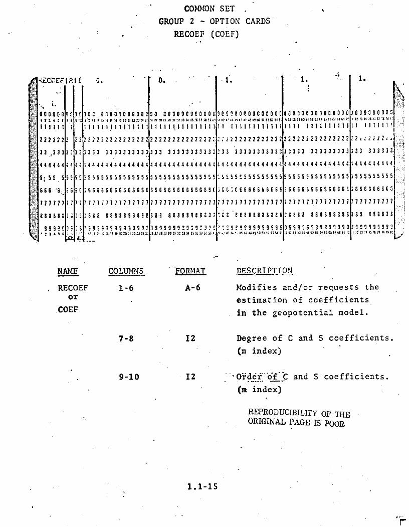
NAME COLUMNS FORMAT DESCRIPTION
RECOEF 1-6 A-6 Modifies and/or requests the
or estimation of coefficients.COEF . in the geopotential model.
7-8 I2 Degree of C and S coefficients.
(n index)
9-10 12 iOrder" o'f C and S coefficients.
(m index)
REPRODUCIBILITY OF THEORIGINAL PAGE IS POOR
1.1-15

NAME COLUMNS FORMAT DESCRIPTION11-25 D15.8 A prioii (or starting) value
of C coefficient.
26-46 D15.8 A priori (or starting) valueof S coefficient.
41-55 D15.8 Standard deviation of C coefficient.
Coefficient will not be adjusted
if value is zero.
Value is fractional uncertainty ifS.. 1.OD- ( /1.OD-5 for J2) andstandard deviation equals fractionaluncertainty times nominal* value ofa priori coefficient. The fractionaluncertainty is the standard deviationdivided-by the a priori value.
Value is standard deviation if<1.OD-5 (Vl .OD-5 for J2).
56-70 D15.8 Standard deviation of S coefficient
Coefficient will not be adjusted ifvalue is zero.
Value is fractional uncertainty if>1.OD-5 and standard deviation equals
. fractional uncertainty times nominal*value of a priori coefficient.
Value is standard deviation if<1.OD-5.
1.1-16

April 8, 1974
RECOEF (Cont.)
NAME COLUMNS FORMAT DESCRIPTION
71-80 D10.4 =0 Values on this card will be
interpreted as being unnormalized.
>0 Entries in columns 11-40 of
this card will be ignored. A priori
values of coefficients are obtained
from current geopotential model
including all modification prior to
this card. Input standard deviations
are un-normalized.
<0 Values on this card will be
interpreted as being normalized.
IF CARD OMITTED: The geopotential used will be.the GEM 1Model unless modified by EARTH card or modified in ARC SETby option cards, EARTH and RECOEF.
See also ARC SET, OPTION CARD - RECOEF.
The geopotential coefficient denormalization equationused is:
Cm = Cm , Dmn n n
Sm = S * Dmn n n
1.1-17

where
.DM (4n + 2) (n m)! for m o(n + m)!
Dnm 1 2n + i for m= o
and
CM, Sm are un-normalized coefficients
C Snm are normalized coefficients
*Nominal values of geopotential coefficients are
(10-5) DmJm n
n
A Priori Value of Adjusted Coefficients
If it is desired that the starting values of geopotentialcoefficients be different than the'a priori values for thosedoefficients then the RECOEF card should be used as follows:
* RECOEF cards requesting the desired coefficientadjustments should be included in the setupdeck. The a priori values will be indicated onthese cards.
* For each coefficient pair for which the startingvalue is to be different than the a priori value,an additional RECOEF card should be in the setupdeck. This RECOEF card will indicate the start-ing value and come later in the deck than thecorresponding RECOEF card requesting adjustment.
.N. m

COMMON SETGROUP 2 - OPTION-CARDS
RESID
-*
R s ID
000000Iniae ' harsd-
2 222 2
66 1.666-166i. Z69:.
7 Ii 0 - Indicates no residuals are
requested for any arc.
1 - Indicates that residuals
are requested on the first
inner iteration of the
first outer iteration for
all arcs.
11 11 .'::::: :::':::::::': :'::::'~:' :::1:.- 19 ~'::~

RESID (cont.)
NAME COLUMNS FORMAT DESCRIPTION cont.
7 (Cont.) 2 - Indicates that residuals
are requested on the last
inner iteration of the last
outer iteration for all
arcs.
3 - Indicates that residuals
are requested on the first
inner iteration of the first
outer iteration and the last
inner iteration of the last
outer iteration for all arcs.
4 - Indicates residuals are
requested on all iterations
for all arcs.
IF CARD OMITTED: Residuals are printed out for the first
and last iterations of each arc unless
modified in each arc by the RESID card
in ARC SET.
See also ARC SET, OPTION CARD - RESID. REPRODUCILITY OF THE
ORIGINAL PAGE IS POOR
1.1-20

COION SET
GROUP 2 - OPTION CARDS
RSTART
SRSTARTEE 17. . . '
2 2222 2 2 2222222222 222 2 2 2 2 Z 222 2 72::1~..2 ..22? 2 2 2. 22222 2
j3 ~~33 33 33 33 33333 333333333 33 j 2 33*1 .Z 3
444444 44'4444444444444 * - 444
5555555 55455555555555 5;0 50 4 4 4 4 4 4
66666 6i3 ' i "6 5 6 6 6 6 65 6 6 6 E' .;..... :r f.e-
5 .ru f
777777771777 7777 77777 7 7
' 7 T:
7 1 " 7: . "7 11
9888 81, 8 8 -3 " .'" a 8 a 8 8 8 8 .8 ' " " 8 t :.' :?....- :
X 4 /
14 12223244-i, t - 7
REPRODUCIBILITY OF THE
ORIGINAL PAGE IS POOR
NAME COLUMNS FORMAT DESCRIPTION
RSTART 1-6 A6 Requests the restart of a
previous run and/or requests
that a restart tape be written
.in this run.
7-8 12 Unit numaber of input restart
tape. If zero or blank, job will
start from the beginning.
9-10 I2 Unit number of output restart
tape. If zero or blank, no
output rertart tape will be
written.
1.1-21

RSTART (Cont.)
NAME COLUMNS FORMAT 'DESCRIPTION
11-25 D15.8 Number of arc in which termination
occurred. If zero or blank, the
job will start from the beginning.
IF CARD OMITTED: The job will start from the beginning and
no output restart tape will be written.
NOTE: Set up changes may not be made such that the size
or configuration of the normal matrix is altered
when restarting.
REPRODUCIBILITY Op TEORIGINAL PAGE IS POORTHE
1.1-22

COMMON SET
GROUP 2 - OPTION CARDS
SEQDAT
z -- , . . .. . . ..-.u.. . ;.J . .. . ..s .u .h.h . ... .. s.. , ... . . ,.. " . " ' ni .. ., .., ,. . ,m .. .J. ' .7.. J.'u. , , , l.n, . ".d ... ,.. ,.II I ,. -... .. !: : .; ., ,.:: i.,.,; .. .'f '?:.1: -;: :: !!:. ':.. . : ,. . . ' . " . " ' ' , .' . ;, :.
..... ........ .
0.. h. .........
22222 2. . . . . .. . . :...._...-
. . . .. .. . . . . . . . . . ..'. . .. : ' .- ,. .: .:iL - ;' . i • ........ - ... . . ..
IN 6PAG P
IF CARD OMITTED: Makes no assumption as to order of arcs.
' ' ., ." ... " " ': ' : ': -.". . .. , "-: " ' ., • .. : ' " .:
• .. . . . ;. . , . : ,..: , . ', ,/.. ". . .. .,: ....'.. : , -', ":'. . .t , ' . .. . : . , .' d:..E " , .i.. , . I :,
,m . -" "' ." ': . : " ' .' ' .. '" !,:,: -": " ,: '.: ':. :' '" .. ''; .:; . :"; "." ': ' '" ''" ',," ," ' , " . " ":" I', ."::I',' ' , " .7 .. .:-..: ; : -': ..: .'. " , .' i .. .' .... "
6 b 6 6. : ., : . . .... - ; . . . ' ., . • , . . -'. .• , -,, , , , ' . .i. . . . . ' .. . " , , .' ., , .: ' .', . ; . '
.,., .: .. ... ....., ... . .. . ... .. . ...,. ., .. .. ..1.•.., • . ',,.". • .• .. .. :. .. ... ' .-
': - '. . i .. .. .. .. : ". '. . : ' " . ' .3 "- . ' .' ,.. " , ' ., ; " . ', .. . . • .. ' '- .. "'. .' '- . . ' - . .. . --!!l 9 } ... ... . .. .... " :" : .. . .... .. ... . .. .. ........ . .. .. .:. .....-. .... , ... . -• •. . .. . -.. .. --S ;:;. '" ... :. "[" '"- .: : .. . :. . - i . .. .-:'. , . .. . .' ., ::. ...:.: .. . . .- . . . . .: j .', .".: '
I : 4 $ i . .. ; . . - . ' ", -; :. 2 .' .. , . '. ,., ,' :-: ',!, "" '# K ' . :. . ::,: .: . '. .: : .- - '-.i:, ,: : :!. L. : ... -. ?.1":' : . ; ' [. ' ,, :
NA [E COUN OMT ECIP O
-

COMMON SET
GROUP 2 - OPTION CARDS
STAEST
.STAEST : 1128. IO. 10. 100. 1032.
000000 000000000000 0 0 0 0 0 0 0 0 0 0 0 0 0 0 0 a 0 0 0 0 0 0 0 0 0 0 0 0 0 0 0 000000 0 0 0 0 0 0
111i 0tt1111 1111111 2111111 1 1111 111111 111 111111111 1 I 11111111111111 11111 1 111 I
2222222 2 222222222222222222222222222 22 22222222222 22222222222222 222 222222222
333333 33333333333333333333333333333333333333333333333 333333333333333 33333333
4444444 444444444444 4444444 444 444 4444444 4 44444444444 444 44444444444444444444 4
77 77 777 7777777?77777 77 77 77777777 77 7 7 7 7 77 1 7 77 7 7 7 7 7 7 7 77 177 7 7 7 7 7 7 7 7 7 7
8 a 88 8 a 88888888888 a a 8888888888888 a 8 a 8 88888 88888 a 8888888888 8 8838 8888838
9999 993 93 99999 9 999 9 9 9 9 9 S 9 S 9 ,9 S 2S 3999999999 33 9 9 9 9 9 9 999 9 9 9 9 9 3 999 5 31 34 4i .4 ?1.,v 21:3 :: n 3x s r u 3a 41 A c.: 51: I 1 12U 66. ; . ; S : *: 4 'I'IL
NAME COLUMNS FORMAT DESCRIPTION
STAEST 1-6 A6 Request estimation of a
station position.
7 .11 =1 - standard deviations
input on station earth-
fixed X,Y,Z
=blank - standard deviations
input on station latitude,
longitude and height.
11-25 D15.8 Station number.
26-40 D15.8 Standard deviation cf X in
meters or latitude in seconds
of arc.
1.1-24

Iarch 1, 97
STAEST '(Cont.)
NAME COLUMNS FORMAT DESCRIPTION
41-55 D15.8 Standard deviation of Y in
S. meters or longitude in seconds
. of arc.
56-70 D15.8 Standard deviation of Z in
S. ' ..meters or height in meters.
71-80 F10.4 Master station to which the adjust-
ment of this station is to be
... constrained. .If station is
unconstrained or a master station
leave bla'nk.*
IF CARD OMITTED: Station positions will be held fixed.
NOTES: A STAEST card must be present for each station to beadjusted. If two or more stations are constrainedone of these stations must be specified as the masterstation by leaving columns 71-80 blank.
A maximum of 381 unconstrained and master stations nay
be adjusted. The total number of adjusted stationsincluding constrained stations may not exceed 381.
.STAEST card's mnay not be present for stations thatare not in the tracking complement.
"See CORREL card in this section for definitions ofconstrained, unconstrained, and master stations.
See also STAPOS card. REPRODUCIBILITY OF THE
ORIGINAL PAGE IS POOR
N II.

COMMON StT
GROUP 2 - OPTION CARDS
SSTEP
-STEP 0.25D-4 0.25D-10 400. 12.5
000001 , , ... l , O 0000000000 0000 00000000000000000000ooO0000 0 0 0 0 0 0 000
2 $ 1t .i'. Il
21 l2S21ll'iii 1 I ! i 1 1 I 1thi i !1 t
22222Z 222 2 22 2 2 2 22 2 2 2 2 2 2 2 2 2 2 2 2 2 2 2 2 2 2 2 2 2 22 2 2 2 2 2 2 2 2 2 2 2 2 2.22, ..... ..... :222222222222222222...2222222222222222222222222222
2 2 2
3 33333 333i::ii ::::33i-%::!i : : 3 3 3 3 3 3 3 3 3 3 3 3 3 3 3 3 3 3 33 3 3 3 3 3 3 3 3 3 3 3 3 3 3 3 3 3 3 3 3 3 3 3 3 3 3 3 3 3 3i333333 . . 3 3 3 3 3 3 3 3 3 3 3 3 3 3 3 3 3 3 3 3 3 3 3 3 3 3 3 3 3 3333333333333333
3 3 3 3
44444 >4444444444444444444444444444444444444444444444444444444
5 5 51. 55555555555555 5555555555 5555555S5555555555555555555 5
6 66 6 6 :. 6 6 6 6 6 6 6 6 6 6 6 6 6 6 6 6 6 6 6 66 666 666666666666 6 6 6 6 6 6
7 7 ...7.7.7.7 7.:: .,.. 777 777i1 7 77 7 7 7 7 7 7 777711 7 7 7 177 777777 7 7 7 7 7771171 7 7
,;0:i . ,. *.":%: .::: .:')1 9 9 9 9 9 9 9 9 9 9959 9 9 9 Sig S 9 9 9 9S 9 S 3 9 9 9 9 9 9 9 9 3 9 9:t. . i 4Z 4', &: 4' Q .. 5
REPRODUCIBILITY OF THEORIGINAL PAGE IS POOR
NAME COLUMNS FORMAT DESCRIPTION
STEP 1-4 A4 Modifies variable step
integrator error bounds
and/or maximum and minimum
step sizes.
26-40 D15.8 Error tolerance for step
size decrease. Default is
0.25D-4 m.
41-55 D1S.8 Error tolerance for step
size increase. Default is
0.15D-10 m.
1.1-26

a. larch 1, 1'
. STEP (Cont.).* . .. . . .
NAME -COLUMNS FORMAT' DI-SCRI PTION
."56-70 D15.8 Maximum step size in variabl
* .: .. ' step mode. Default is 400
.. K * .... seconds.,-* •
' •
.
71-80 -'D10.5 . Minimum step size in variablc
" • step mode. Default is 12.5
-. , seconds.
--- -. • '*.. . .
IF .CARD OMITTED: Default values given above are usedunless modified by STEP card in ARC SET.
NOTE: Only those bou"nds for which non-zero values appearon the STEP card will be modified.
See also ARC SET, OPTION CARD - STEP.
REPRODUCMhILi.G.NL PAGETHV !
• oo. p• I ?o

'. .* COMMON SET
GROUP 2 - OPTION CARDS
. SURDEN
A I
.U. .D N.6 . . A .S.. . .. . .... ... ..
7 su f c . *i . t o ... .
,."" .. -L" ' 1. : ? . *..) . ."
SURDE .. 1-6 2A6 Spcifies nubcr of intervals i
ICface dcnsities. The triv ial c.-:
S.... . . degenerats to a Mascon.
7-8 12 N fumber of latitude intcrvals.
.. Default o a a n
9-10 12 Number of longitude intervals.
Default= 1
' REPRODUCIBILITY OF THE
IF CARD) OiTTED: Default values usd. ORIGINAL PAGE IS POOR
,. 7 . *0 ..

GROUP 2 - OPTION CARDS
SURF
I I I I I I 1 1 1 1 1 , l l 1l ?7 l l2 ?T 11 ....
j .. . r
:'. U ' JUU
'j ""0 ' -. . • . "
2 222222222222222222222222: :?22222222222222222222222222222222*222 ,-- .' ..... -S333333, 33 3 3333333333333 3 3333333 3 33, 333333333333333333 3333333
j4444 144444444444444444444444444444444444444 4 444444444 4 4 4"
0 ' a a a 04 C "S RA :^ , D "CP I .-1 8 aa a6 " 3 S 3 a a 8
9 9 0 9 2 13 3 Sel. 19 9 9 9 9 9 9 9 3 9 F e. 2c 3 3re rr S 3 3 1 1 err 9rr-c 1 er e 9 CC C Et.
in kg/m" .
1117 ' 7.171777777 777.717117777777717 17"11717717 ' I-
26-40 D15.8 Value bf surface density standarddeviation.in kg/m
"NAME COLUMNS FORMAT DESCR I PTI ON
SURF 1-4 . A4 . Specifies application and/or estiuationof surface densities
11-25 D15.8 A priori value of surface density
1.1-28
in kg/m
Default = 0.
26-40 D1S.8 Value bf surface density standard
deviation in kg/m 2.>0 results in estimation of surfacedensities.
a ODUCIJILIT OF TE
1.1-28

SURF (Cont.)
NAME COLUMNS FORMIAT DESCRIPTION
41-55 D15.8 Value of geocentric latitude at
center of master block* in
degrees.
56-70 D15.8 Value of east longitude at center
of master block* in degrees.
A second card must follow the SURF card in the input stream.
The format of this card is:
NAME COLUMNS FORMAT DESCRIPTION
1-6 A6 These columns must be blank.
7-8 -12 Number of latitude subdivisions
in master block.*
Default = 1
9-10 12 Number of longitude subdivisions
in master block.*
Default = 1
11-25 D15.8 Size of each latitude subdivision
in degrees.
26-40 D15.8 Size of each longitude subdivision
in degrees.
WARNING: Failure to provide the second card or to specify
sizes of latitude and longitude subdivisions will.
result in program termination.
IF CARDS OMITTED: Surface densities will not be applied.
REPRODUCIBLITy OF TJHE1.1-29 ORIGINAL PAGE IS POOR
1W

".M arch 1, i4 . . " .
SURF (Cont.).*
NOTES: Surface densities are an expression of deviations frc..the earth's gravitational potential as defind bythe spherical harmonic expansion of the geopotential
* *.. coefficients. ..
Surface densities are applied in GEODYN as uniform. .layers of mass covering areas of the Earth's surface.
These areas are defined as the area of blocks boundedby lines of latitude and longitude.
*A master block is an area bounded by lines of latitudeand longitude which may be subdivided into blocks ofequal size (in terms of boundary lengths in degrc'csof latitude and longitude) each of which has the sar.a priori valuc of surface density.
A master'block may be so-constructed as to containonly 6nc block. This is the program default if thenumber of subdivisions is zero.
For convenience, master blocks are used in GEODYN toinput surface densities.
A maximum of 674 master-blocks may be specified.
* *
. -
iI

*, • * * .. . .'* = ,
SCOMMON SET "
GROUP 2 - OPTION CARDS
TIDES
. • . . . .
IL ES :1 .
•I. - .
, s t" Ii 14 l " IS ,i .2.. ?324 .. 27 .2930 2 4 3i ' ... , S -' ...... . *. . '
1I;1 1111111111111 1111111111111111 * . ii, l1 I l i i i a I I i
22 22 2222 2 22222?? 22222222222222222222 '. 2
S333 3" 3 3 3333. 3333333 3333 3 3 3 "3 3 3 3 3.. .
4 " 4 4 4 4 4 4 4 -1 4 4 4-4 4.' ."4"4.4•4
' 4" . . ..4 . .
55 5.5 •. 55555555 555555 55555 "5555 5 5 5 '.44" SS .44S44. 44444444444.,"s56 SE S 6 6 -. . . -. -.
9 q: rSS9 9S .... " :SSS' i : :S ' 3.1z 13 "4 --"i 1" is :2 I2;i:.' 2 :. U .1 0 11 32 13 31 2. .it -
REPRODUCIBILITY OF THE
NAME COLUMNS FORMAT DESCRIPTI ORIGINAL PAGE IS POOR
TIDES 1-5 AS Modifices earth tide perturbations
7 - II =0 This card pertains to both
Lunar and Solar tidal effects.
.1, This card pertains only to
' " Lunar tidal effects.
=2, This card pertains only to
Solar tidal effects.
1.1-31

NAME COLUMNS FORMAT DESCRIPTION,
. 8 11 Indicates which tidal coefficient
.is to'be modified.
Value" Coefficient
S. 1 K2
• .... 2 K3
."-3 K2 - Phase
-. - A value of zero in this column
will set all coefficients to zero.
. 11-25 D15.3 Value of tidal parameter being
modified.
Defaults:
. Coefficient Value
S." K2 0.29
K3 . 0.0
K2-Phase 2.5 Degrees
26-40 D15.3 Standard deviation of tidal co-
* efficient. If non-zero value is
specified, tictl paranctcr will
be adjusted. Default values are
all zero.
. If card omitted: Default values given above are used.
REPRODUCIBILITY OF THE* - ORIGINA.L PAGE. IS POOR
* * 1.1-32

'COMMON SET-
GROUP 2 - OPTION CARDS
TOLS
CLs I 0.25D-7 0.25D -10
Do 00i 02000000 00000 Ca0000000 0000 0" .P."F 4iSI I 1,. 12.13 14 S , 1.. 1-., :... ::.;- 2.22;..30. :. ::4 2- S. a 2930 31. U:..: 3.3.:. 4 ,s.
S222: 22272 22222222222222222222222222222 2 2 2 2 2 2 2 2 2 e
3' 3 3 3 3 3 3 3 3 3 3 3 3 3 3 3 3 3 3 3 3 333333333 3 3 3 " '
444444;: ;4444444444 4444444444444 444 4 4 44 4 1 .4:
555555 5 5 55555555555555555555555 5 555 , . . . . 5
6 6 6E E -3 66 66 6 66 6666 6 6 6 65 6 5 6 6 6 6 6 6 6 :' :.
1177777771 C 7 7777 177777 77 177 77 ' 1 7''77 7 7 7.7 7 ;, :
.818888 & 3 2338 8 8 8 8 3, a .8. 8 338 0....
9 9 9 9 9 9 9 9 99 ~999 S 9999 9 3 9999999 9 9 . .:' :- ..*"" 34 " .:.14 n I I; I; 2 2: 222 3 ;4 I , 3 78 . 1 32 3 4 :5 is 31 ' 4 -: -. . .
NAME COLUMNS FORMAT DESCRIPTION
TOLS 1-4 A4 Modifies integration tolerances.
7 Il Indicates for which satellite
tolerances are to be modified
for all arts.
O both satellites
1 first satellite
S2;second satellite
b
9-10 12 Maximum degree and order of
REPRODUCIBILITY OF THE
ORIGINAL PAGE IS POOR
1.1-33

TOLS (Cont.)
NAME COLUMNS FORMAT DESCRIPTION
9-10 (Cont.) geopotential effects to be
included in the computation
of the variational equations.
Default = 4, Minimum = 3.
11-25 D15.8 Desired reasonable predictor-
corrector tolerance to be
achieved by changing the inte-
grator step size while in variable
step integration mode. Used
only in computation of new
step size during step size
variation.
Default = 0.25D-7 m.
26-40 D15.8 Critical predictor-corrector
tolerance. Used to determine
number of corrector iterations
necessary at each integration
step. If after 2 corrections
the. local error exceeds critical
POGNDGlS P001 tolerance an-error message will
be printed (execution will be
terminated).
Default = .0.25D-10 m.
41-55 D15.8 Maximum degree (and order) of
gedpotential coefficients for
which constraint equations will
be included in the estimation
of surface densities. Default = i1
IF CARD OMITTED: No modifications will be made to
integration tolerances.
1.1-34

• .. •March 1, 19
1.1.3 COMMON SET
GROUP 3 - STATION COORDINATE CARDS
" " STAPOS
CARD TYPE FORMAT COLUMNS DESCRIPTTON
Starting Card A6 1-6 The word STAPOSbeginning incolumn one.
• ."" Ii 7 >0 indicates station. adjustment signaIs on
this card appl.y toEarth ccntered fixed
. -. Cartesian coordinates.
1 . 8 -0 indicates that no. station coordinates
S . are to be used frco.. built-in coaplc:ment.
D15.8 11-25 Sigma in seconds ofarc for station latituc Sor-rme.trs for stationECFX.
.. D15.8 26-40 Sigma in seconds ofarc for station longi-tudes or meters forstation ECFY.
D15.8 41-55 Sigma in meters forstation height or ECZ.
NOTE: If values greater than zero appear in columns 11-25,26-40, and 41-55 then all stations will be adjustedusing the sigmas input on this card. Stations forSwhich STAEST cards are present will use the signiasspecified on the STAEST cards. Default is that onlystations specified on STAEST cards will be adjusted.
REPRODUCIBILITY OF THEORIGINAL PAGE IS POOR
S *

GROUP 3 - STATION COORDINATE CARDS(CONT,)
CARD TYPE FORMAT COLUMNS DESCRIPTION
Station A6 1-6 Station NamePosition CardPositior ,h input 14 7-10 Station Numberfor O,X,h input
Al 11 Sign of Latitude
2 12-13 Degrees Station
Se, 12 14-15 Minutes Geodetic
F10.8 16-25 Seconds Latitude
Decimal may appearonly in col. 18.
3 26-28 Degrees Station
' ,I 12 29-30 Minutes East
F10.8 31-40 Seconds Longitude
Decimal may appearonly in col. 33.
D15.8 41-55 Station Height in hMeters
Al 56 7th character ofstation name.
.Station A6 1-6 Station NamePosition Cardfor Earth-Fixed 14 7-i0 Station NumberCartesian Coor- D15.8- 11-25 x in metersdinates D15.8 26-40 y in meters
D15.8 41-55 z in metersAl * 56 7th character of.
station name
REPRODUCIBILITY OF THEORIGINAL PAGE IS POOR
1.1-36

S: . . .. . . - . ..
GROUP 3 - STATION COORDINATE CARDS(CONT.)
.° . - .. S.
NOTE: GROUP 3 is necessary only if the tracking complement
built into the program is to be changed or replaced.
The number of station position cards must not exceed
381. . -
These cards are Optional. -
The station height is measured in meters above the
reference ellipsoid. See EARTH card, COMMON SET,
GROUP 2 - OPTION CARDS.
See Appendix D for built-in -station positions.
REPRODUCIBILITY OF THEORIGINAL PAGE IS POOR
1.1-36.1IF

1.1.4 COMMON SETGROUP 4 - TERMINATION CARD.
NAME COLUMNS FORMAT DESCRIPTION
DATA 1-4 A6 Designates end of COMMON SET.
7-8 12 Convergence criterion* for
outer iterations in percent.
"Default is 2 percent.
9 II Minimum number of outer
iterations. Default is 1.
10 . 'Maximum number of outer
iterations. Default is 1.
This card terminates the CONMION SET containing cards to
define information common to all arcs and is Mandatory.
*When
RMS previous outer iteration -RMS current outer iteration x 100 (converge:
" criterioiRMS current outer iteration
convergence has been obtained. On the first ouzer iteration
the values of the RMS for the previous outer iteration is, by
default, 1000. This can be changed by using columns 26-40 of
COMMON SET, OPTION CARD----EDIT.
Inner and outer iterations are explained in the Introduction
of this manual.
1.1-37

1.2 ARC SET- " ;.• . .
'ARC SET contains that information which is necessaryto define each individual arc.
"'.: Included in ARC SET are four groups:
.1. Arc description cards which are .three titlecards, the Reference Time card, the Epoch card,and the Epoch Orbital Element cards. (Mandatory)
2. Option cards which may be used to exercise theI GEODYN individual arc capabilities. (Optional)
3. Termination card for Group 2 - Option Cards.
(Mandatory)
.4. .Selection/dcletion cards to exercise GEODYN's.data selection and dcletion capabilities.
(Optional)
The. following .pages describe these groups more thoroughly.
0 *
S - REPRODUClBILITY OF THEORIGINAL PAGE .IS POOR.
1.2-1
1'

1.2.1 ARC SET
GROUP 1 - ARC DESCRIPTION
CARD NUMBER FIELD FORMAT DESCRIPTION
1A 10A8 Three title cards for each arc.
1B 10A8 Columns 1-80 of each card are.
iC 10A8 printed as identification on
all output from the arc.
2 16 Year, month, day of the
reference time (YYMMDD).
3 See Section Epoch card.
1.2.1.3
4A 3D24.16 Element card one (Position
vector).
4B 3D24.16 Element card two (velocity
vector).
These cards are Mandatory for each arc and are more fully
explained on the following pages.
If two.satellites are in the arc cards 4A and 4B should
be repeated specifying the second satellite epoch elements.
(See EPOCH card.)
REPRODUCIBILITY OF THEORIGINAL PAGE IS POOR
1.2-2

ARC SET
GROUP 1 - ARC DESCRIPTION
TITLE CARDS
* -_ . -5 DAY GEOS-II ARC -- ADJUSTING SOLAR RADIATION-
.0000000000goooo c cc ooooooooooo0000000000000000000000000000000000000000cl......I
2211 2 2 2 2222 2222222 22222 222 2222222222 222222222222= 22222222222222 |2
3333333333333333333333333333333333333333333333333333333333333333333333333333
44444444444444444444444444444444444444444444444444444 44444444444444
555555555555555555555555555555555555555555555555555555555555555555555555555555
6 6 6 6 6 6 6 6 6 6 6 6 6 6 6 6 6 6" II::
666666666666s666666666
5 2 3 4 s i ii 18 ;5 5 5 5 5 5 5:1 5 5 .5 5 5 5 5 55 5 5 5 5 5 5 5 5 5 55 5 5 5 5 5 5 5 5 5 52 ; 5 5, 5 I5 5 5 5 5
1 77 7 77 7 7 7 7 7 7 7 7 7 7 7 7 7 7 7 1 71 7 7 7 7 7 7 77 7 7 711 7 771 77 7 7 17 7 7 1 177 7 771 :::.'
5081 BSC * - -
CARD COLUMNS FORMTAT DESCRIPTION
1A 1-80 10A8 Identification to be printed
1B 1-80 10A8 on all output from arc.
lC 1-80 10A8
Three title cards are Mandatory for each arc.
REPRODUCIBILITY OF THEORIGINAL PAGE IS POOR
1.2-3

* ** , lparch 1
. c* .!
ARC SET
.GROUP 1 - ARC DESCRIPTION
R3FERENCE TIIIE CARD
,. : ..
.' ..
COLUMNS ". FORMAT DESCRIPTION
1-6 :-'16 .Ycar, month, day of refer-
S-ence date in YYIMDD.
Note: This time defines the inertial coordinatesystem in which the program 'will integratethe orbit. The .reference time should precedeor be the same as the epoch of the initialelements.
-'Thie input epoch elements are assumed to be in
the -inertial coordinate system defined by the- true equator and equinox of the refe -rnce time.
* The estimated (adjusted) epoch elcments arealso in the same cccrdinatd system.
It is critical to proner program oneration that
* each column from 1-6 contain numerals between0 and 9 and that no blanks be present in thesecolumns. Columns 7-80 must rema in entirelyblank.
This card is Mandatory for each arc.
* EPIOUILNAL PAGE IS P''R n• DJUCGNAL PAGE IS POOR

ARC SET
GROUP 1 - ARC DESCRIPTION
EPOCH CARD
COLUMNS FORMAT DESCRIPTION
1-6 16 Epoch date of the initial ele-
ments of the arc in YYMMDD.
7-10 14 Hours and minutes of epoch in
HHMM.
11-17 F7.4 Seconds of epoch in SS.SSSS.
18 I Maximum number* of inner iterations
on all outer iterations except the
first for this arc. The default
is 1.
19 11 Maximum number* of inner itera-tions for this arc on the first
outer iteration. The default is 1.
20 Il Minimum number of inner iterations
for this arc. The default is 1.
21-22 2PF2.0 Inner iteration convergence criteria
for this arc. The default is 2 per-
cent.
23 Il1 Tape format flag.
1 - indicates GEOS-1 Data Center format
0 - indicates binary DODS data tape
2 - indicates GEOS-2 Data Center format
3 - indicates PCE format
4 - indicates SIMULATED Data format
S - indicates GEOS-C Data format
6 - indicates RAP Binary Data format
1.2-5

EPOCH CARD (Cont.)
COLUMNS FORIMAT DESCRIPTION
24-29 16 Cutoff date for data in YYMMIDD.
30-33 14 Hours, minutes of cutoff time fordata in HIM4.
34-40 F7.4 Seconds of cutoff time for data
in SS.SSSS.
•41-46 16 Start date.for data in YYMIDD.
47-50 14 Hours, minutes of start time for
data in I-IMM.
51-57 F7.4 Seconds of start time for data
in SS.SSSS.
58 Ii Number of satellites. Default = 1.
59-64 17 DODS Data Base element set number.
65 Ii DODS Data Base element retrieval
flag (See Appendix A).
66-72 17 Satellite iD for element retrieval.
77-80 A4 This field is used to alter the atmos-
pheric density model used for the arc.Models available are:
1.2-6

August 11, 1973
MNEMONIC DESCRIPTION
J65 Jacchia 1965a modified to
1968 (see option card of same
name).
J650 Old Jacchia 1965a modified to
1968 (see option card of same
name).
J71 Jacchia 1971 model (see option
card if same name).
This card is Mandatory for every arc.
1.2-6.1

EPOCH CARD (Cont.)
NOTES: The Epoch and start and stop times for data must
be specified in the UTC time system. The default
for the data start time is Epoch. No data prior
to the start time or later than the cutoff time
will be accepted. Orbit integration will be initiated
from Epoch or the data start time, whichever is
earlier. The data start time may be used during an
orbit generator run to specify the earliest time for
orbit integration. A cutoff time specification is
mandatory only if the data is being read from the
DODS data base. (See Appendix A.)
If the data start time is earlier than Epoch, integration
proceeds backward from Epoch to the start. Epoch is then
reset to the start time, and integration resumes forward.
Inner and outer iterations are explained in the Intro-
duction of this manual.
*If column 18 contains a 1 andcolumn 19 is zero or
blank the defaults for the maximum number of inner
iterations will be 10 for the first outer and 1 for
subsequent outer .iterations.
1.2-7

ARC SET
GROUP 1 - ARC DESCRIPTION
POSITION VECTOR
7265983.5426781 0.15321567852165 13.2456854216545
ooooooooooooo00000000000000000000000ooo00000O000000000000000OOOOOCOOOOOOOOoo000000000qooo00qcoi 3 4 3 5 1 1 1 10 11 12 13 W I 16 1a 11 20 2122 n 24 n 26 27 N 2S 30 31 V n 3 Z X 7 3 33 Q 41 42 43 44 45 Q 41 4!1 5 It U 53 4 55a 5S0 3 S 5 r. 6 1 62 93 6L 66 6 69 a s 70 It 7
11111 11111111|17111111 11 11111111 111111111111 i1111111111 11111111111111 1 1111
22222222222222222222222222222222222222222 222222222222222222222222222 22222 22222
333333333333333333333333333333333333333333333333333333333333333333333333 3
44444444444 444444444 4444 44444 444444 44444444444444444444444444444 444 44444444444444444 ., ,
55555555555555555555555555555555555555555555555555555555555555555555555
6 6 66 6 66 6 6 6 6 6 66 6 6 6666 6 666666 6 6 66 6 66 6 6 6666 6 6 6 666 66 6 66666 6 6 6 6 6 6 6 6 6
7 77777777177 1177 117 17 7 717771777 171177 7 7 7 777777 7 7 17 7 77 77 7 7 7 117 7 1 7 7 1
995 99999999 9999999 9 9 9 9 9 9 9 9 5999 9 99 9 9999999 9 9 9 9 9 99 9 9999 9 9 9 9
5081 BSC -
COLUMNS FORMAT DESCRIPTION
1-24 D24.16 x Component
25-48 D24.16 y Component in meters
49-72 D24.16 z Component
of satellite position at epoch
time, in the inertial coordinate
system of the reference time, or
osculating Keplerian elements.
a (in meters), e, and
i (in degrees).
REPRODUCIBILITY OF THEORIGINAL PAGE IS POOR
1.2-8

POSITION VECTOR (Cont.)
COLUMNS FORMAT DESCRIPTION
73 11 =0 or blank, orbit will be elliptic.
=1, orbit can be either elliptic or
hyperbolic and the input elements
are Cartesian.
=2, orbit can be either elliptic or
hyperbolic and the input elements
are Keplerian.
This card is Mandatory for each arc.
REPRODUCIBILITY OF THEORIGINAL PAGE IS POOR
1.2-9

ARC SET
GROUP 1 - ARC DESCRIPTION
VELOCITY VECTOR i
56.23548163542897 238.235588665412 385.5423588443554
11111111 i I 1111111 1 11 I111 . 1111 1111111111111 1 11 11111111 1 111 111i: i
22222222 222 2 222 2 2 2 2 2 2 2 2 2222 2222 2 2 2 2 2 2222 2 2 2 2 2 2 2 222 22 2 2 2 2 2 2 222222 2 22222
33333333333333333333333 3333333333333 333 3 3 3 3 33333333333333 3 3 3 3 3 3 3 3 3 3 3 3 3
444444444444444444444444444444444444 4444444444 44444444444 444444444 44
555555555555555555555555555555555555555555555555555555555555555
l5 6 6 6666666 6 6 6 6 6666 6 6 6666 6 6 6 6 666666666666666 66666666666666 666666.
7777777 77 77 77 77 7 7 7 777 7777 77777777777777777 77777777777777777777777"7 7: ;777ii l7:77"7'i7:7
Spa 88888888882888"8888888888 3 888888888888885 888888 1 4 . 3 3 888 88888888 888 . ..
081 OC..
COLUMNS FORMAT DESCRIPTION
1-24 D24.16 : component
25-48 D24.16 $ component in meters/sec.
49-72 D24.16 t component
of satellite velocity at epoch time
in the inertial coordinate system
of the reference time, or osculating
Keplerian elements Q, w and M (all
in degrees).
This card is Mandatory for each arc. See Position
Vector Card - Col. 73.
G12-10L PAGE IS
1.2-10

1.2.2 ARC SETGROUP 2 - OPTION CARDS
Each GROUP 2 card is identified by the name beginningin column 1 and read under an A6 format. The name is followed
by 9 fields:
Field Columns Field Format
7, '8, 9, 10 411
11-25 D15.8S 26-:40 D15.8
41-55 D15.856-70 D15.871-80 . D10.8
The Option Cards are:
BIAS ELCUT SAT
BMATRX ORB 1 SIGMA
BODIES ORBIT SIMDAT
CULL OUTPUT SOLRAD
DRAG PREPRO STEP
EARTH RECOEF(COEF) TOLS
EBIAS RESID VARCOVEDIT TERMEL REGINT
MAXLAT
REPRODUCIBILITY O1 THEORIGINAL PAGE IS POOR
1.2-11

ARC SET
GROUP 2 - OPTION CARDS
ALTMTR
17 .. 1 1.. =1 I I I I I al t I1 1i I -IIIIIIIV .i
.t" ... .. ... eter i::: e :ir.: . f:i.le on. t'h : :
6 66 6 6C6 G E
7 =1 Requests output of an alti-
last iteration. Output is
altimeter attitude error
correction. This correction
REPRODUCIBILITY OF THE contains a bias term which is
ORIGINAL PAGE IS POOR always present. (applicableonly to GEOS-C).
1.2-11.1

ALTMTR (Cont.)
NAME COLUMNS FORMAT DESCRIPTION
9 I1 =1 -Indicates that an attitude
tape for GEOS-C will be
input on unit 80.
IF CARD OMITTED: No such options will .be applied.
1.2-11.2

ARC SET
* GROUP 2 - OPTION CARDS
.BIAS
BIAS 1035 15. 5. 680412153418. 680412183000. 2.
0000 C0000.0 0 0 0 00 0000 0 00 00 0000 0 00 0 0 00 0 0 00000 0 0 0 0 0 0 0 0 0 0 0 000000 0 0 0 0 0 0 0 000 001 2 3 4 I S 1 : 11 12 1] 14 15 16 17 3 11 20 2122 2124 r 26i 21 3 95 3! 31 22 33 3 35 A 37 33 C AV 4? 42 45 4 41 U A 0 51 W $3 54 5- 'A ! I S i6 1 6 I ! 65 S O i 1 I I 72 3 I1 S i S I 7 It 5
222222222222222222222222 222222222222222222222 22222222222222222222222222
33333 333333333333333333 33 33333333333333 3 3333333333333 33333333333333 3333333333
44444444444444 444444444 44444444444444 44444444444444 444444444444444444444444444
5 5 5 5 5 5 5 5555 5 5 5 5 5 555 5 5 5 5 5 55 5 5 5 5 5 5 5 5 5 5 5555 5 5 55 5 5 5 5 5 5 5 5 5 5 5 5 5 5 5 5 5 5 5 5 5 5 5 55 5 5 5 5 55 5 5 5
6 6 6 6 6 66 6 6 6 6 6 6 6 6 6 66 6 6 6 6 666 6666666 6 6 6 66 E6 66 6 6666 6 66 6 6 6 66 6 6 6 6 6 6 6 6 6 6 6666 6 6 6 6 6
7 77777 77777 777777 7 7 777 777 7 7 1 771777 7 7 7777777 777 77 77777 7 7 7777777777 777 7
8888 688888888888 388888388t 8 8 8 8 8 8 8 83 8 88 e 6968888888886 888888888888888888888888c
9S 9 9 9 SS 9 9999 9 9 9 9 999999s99 9 9 99 9I ,:8 i .. :u;74'c'
SBSS 9 9 9
NAME COLUMNS FORMAT DESCRIPTION
BIAS 1-4 A4 Requests adjustment of either
measurement biases or station
timing biases.
7-10 14 Station number for which the
bias is requested.
11-25 D15.8 Optional a priori estimate ofthe bias value in "natural"
units: Length: meters
Angles: radiansREPRODUCIBI]ITY OF THE
ORIGINAL PAGE IS POOR Time: seconds
Mathematical symbols
b - measurement bias
At - timing bias
1.2-12

"BIAS (Cont.)
NAME COLUMNS FORMAT DESCRIPTION
26-40 D15.8 Standard deviation of the
a priori bias in the same
units.
41-46 16 Optional year, month, and
day of the time at which
the bias is to begin.
47-53 F7.0 Optional hour, minute, and
second of the time at which
the bias is to begin. A
decimal point must appear in
column 53.
56-61 16 -Optional year, month, and day
of the time at which the bias
is to end.
62-68 F7.0 Optional hour, minute, and
second of the time at which
the bias is to end. A decimal
point'must appear in Column 68.
71-80 D10.8 Bias type - same as those
listed under SIGMA
cards - for measurement biases
..or zero for timing biases.
IF CARD OMITTED: No measurement or station timing biaseswill be adjusted.
1.2-13

'BIAS .(CONT.)
.Note: The normal procedure for bias adjustment is for
independent biases to apply for each satellite
pass. If this is the desired type of adjustment,
columns 41-70 should be left blank. When start
and end times for biases are explicitly indicated
they will override the pass-by-pass assignment;
however, if there are passes after the stop time,
new biases will be assigned for the passes.
E~RQDBIBILITY OF THEORIGINAL PAGE IS POOR
1.2-14

ARC SET.
GROUP 2 - OPTION CARDS
BMATRX
- I-00 0 0 . O 0 0 0 0 0 0 0 0 C 0a oa 0 0 o 0 0 0 0 0 0 0 0 a 0 C C. . 0. "
2 3 -45 : - i' 1n4 lts t 1 t 1 9 20212223242 :u 2n T 2 s3 as: v : :,, ...2 I ,,J,2 -3 3 353;37 ':" ":
11 ::I II. , ll l l li 1 1 1 11 1 . 11r 11 1111 1 i .;-! r-- .t: 15 'll ri , -it :! 1:-'!j. X. Vi Is l. ,!1 l.. :.:
222 2 222 2222 2222222222222222222222222 A 2 .. 2 :2 22 2 .
s :333 3353 3 33 3 333333333333 3333333333 " 3 ' ' : "T ;"3133 3 3
4 .4444 444444444444444444444444444444 :A . 4,4 . , . s
55555 :,:, 5555555555555555555555555 55, - .: :-
S6 6 6 6 6 6 6 6 G 6 6 6 6 6 6 6 G 6 6 5 6 6 6 6 6 6 5 6 6 : ': - :: : :615
7 7 7 7 7 1 7 7777777 777777777777 71 ." I ', ! 1 7.;'77:i77/:77::7'7 7 7 7 :-77I
888E818 388 8888 8883 88 S888 8888 . -a. a- . + .....8:88 a t a:, .
9999 s I 3 99 S9 99 999 9 99 9 9 9 999 9 9 9 .' : :- :1 ? '. S. 41 5 I .U I 14 1$ I5t1a 20 212223Z4; ; 21 23 ' 1301 3334 35sS ; . ,. : u .1 ." -;..::.. . :.; ; : -1i t* . .
REPRODUCIBILITY OF THENAME COLUMNS FORMAT DESCRY# L PAGE IS POOR
BMATRX 1-6 A6 Indicates that a B-matrix
tape is to be written on
unit 71 for this arc.
11-25 D15.8 B-matrix number to be written
on the tape. This number must
be greater than zero and less
than 10000.
26-40 D15.8 >0 Requests that the B-matrix.also be printed on unit 6.
IF CARD OMITTED: No B-matrix tape will be written.
1.2-15

BMATRX (Cont.)
NOTES: If any arcs write a B-matrix tape then the maximum
number of outer iterations will be one and there
will be no outer iteration adjustment.
Adjusted parameters that will be included on the
B-matrix tape are the following:
Geopotential coefficients adjusted as common
parameters. (See COMMON SET, OPTION CARD -
RECOEF)
Master tracking stations and unconstrained
adjusted tracking stations. (See COMMION SET,
OPTION CARD - STAEST)
Drag and solar radiation coefficients, CD, CD'and CR. (See COMMON SET, OPTION CARDS -
DRAG and SOLRAD)
Satellite elements. (See ARC SET, Run Descrip-
tion - Position and Velocity Vector cards)
1.2-16

ARC SET
SGROUP 2 - OPTION CARDS
BODIES
7 7 7
0 0 0 0 0 a a 0 a 3 3 a a .j 11 a a S L, i L3,j3
5 1. rji
44 444,1 144444444444444 .is 2 2 Z
T ,8888 1 88 8 .1. 1 1.
2 .i 2 2 I 2. 2. 2 2• 2- 2 2': 2... : o:.. : ;,2
.- I -
,, , ,,4 4 4 4 4 " 4 4 4 4 4 4 4 4 4 47.4.:."-i.
BODIES 6 6 6 6 6 6 16 A6 Modifies non-earth gravity 6 3 i
2- SUN
999 99 - VENU EPRODUCIBILITY OF THE9S,
NAE COLUS FO MARS ORIGINAL PAGE I POORON
BODIES 1-6 A6 Modifies non-earth gravity
perturbations.
7 Ii Indicates body for which
gravity perturbation is to
be modified
1 - ,MOON
2 - SUN
3 - VENUSREPRODUCIBILIT OF.THE4 - NARS ORIGINAL PAGE IS POOR
1.2-17

BODIES (Cont.)
NAME COLUMNS FORMAT DESCRIPTION
7 .(Cont.) S - JUPITER
6 - SATURN
8 I1 Number* of perturbing
bodies to be applied
(maximum of 6).
Default = 2.
This number may be set on
any one of the BODIES cards
used in the arc.
11-25 D15.8 Value of ratio of mass of
body to mass of-earth. If
ratio is zero perturbing
effect will be zero.
Default mass ratios:
Ml/Me = 0.01229997171006507
M2/M e = 332945.5619264376
M3/Me = 0.8150003229334958
REPRODUcILITY OF T1E M4 /m e = 0.107446852527Q073
ORIGINAL PAGE IS POOR M/5 Me = 317.8809303
M6/Me = 95.14905175
IF CARD OMITTED: Lunar and solar gravitational perturbations
will be applied using default mass ratios
unless BODIES card is used in COMMON SET.
To omit a particular body for gravitational purposes aBODIES card representing that body must be included with thecorresponding mass ratio set to zero.
*For example, if the number of perturbing bodies is 4 then theeffects of bodies 5 (Jupiter) and 6 (Saturn) will not beincluded, etc.
See also COMMON SET, OPTION CARD--BODIES.
1.2-18

ARC SET,S GROUP 2 - OPTION CARDS
CULL
CULL 823. 415. 418.
ooo00000o ::-t. ooooooooooooo0000000000000 ooooooooo00000000000000ooooo ooooooooooooo ooooo0000000000000ooooooo 2O1.1 11::: 11 1 111111111111111. ! 1iI! .11 I 11I 1I1111 11 111 .11 111 11 1 1 ::......?lI..!..:i:...: :
22 22 ':7::?:: 222222222222222 22222222222 22222222222222 222 2222222222 2 2:::::.' ::iii::ii -:.
33 33 !ii~i~: :1 3333333333333 333333333333333 33333333333333 333333333333333 ....;.:3.l:- .-44444 4 44 44 4444444444444 44444444 4444444444 4 4444444 44444444444444 :; , ' 4:%l:- --
555555 555555555555555555555555555555555555555555555 55555555555555 ............:.
6 66666 66666666666 a666666666666668 6 666656 666666 6666666666 ;.666 -:6.::-
7777 .. . .1 17:i: 77777777777777 7 177771777 77777777 77777777777777 7777 777 7 1 :... .?. I..
88 88 ' 88888888888888 888888888888 888888 88888888888888888888888 : . 2'c i . .99 9 3 3 3 3 3 3 3 3 3 3'3 9 3 3 3s3 3 3 1 33 3 339 3 3 339 9 9 339 3 39 3 3 3 9933 939399999 9 .:.. ...5l
NAME COLUMNS FORMAT DESCRIPTION
CULL 1-4 A4 Used to delete individual
meas'urements from the
solution by zero weighting.
11-25 D15.8 The number* of the first measurementin a series to be deleted.
26-40 D15.8 The number* of the last measurement
in a series to be deleted; may
be left blank if there is
only one measurement in
REPRODUIBILITY OF THE *the series.ORIGINAL PAGE IS POOR
1.2-19

CULL (Oont.)
NAME COLUMNS FORMAT DESCRIPTION
41-55 D15.8 The number* of the first
measurement in second series
to be deleted.
56-10 D15.8 The number of the last measure-
ment in second series to be
deleted; may be left blank if
there is only one measurement
in series two.
IF CARD OMITTED: No measurements are deleted.
NOTE: A maximum of 50 cull cards may be used per arc.
The series may fall in any order, and tico series
per card are not necessary.
*The numbers which correspond to each measuremn.t are
printed at the far right of the residual printout.
1.2-20

ARC SET
GROUP 2 - OPTION CARDS
DELAY
..L. ..... . .. ...
0000 00 L 00 0 0000 300000 0 0 0 0 0 0 0 0 0 0 0 .0 0 0 0 0 000 00.....3 3 4 I " :1 ? 3 1 192~ !2: 232 2 t ' 9 31 32 34 :5 36 57 M 21 AC 41 42 43 44 7 45 47 4895051 52 5354 5:
22222222222222222222222222222 2222222222222222222222222 2222222222........... ...........
33 33 3 3 3 3 3 3 3 3 3 3 3 3 3 3 3 3 3 3 3 3 3 3 3 3 3 33 3 3 3 3 3 3 3 3~ 3 3.......3 3 3 3 3333:~
5 5 55 55 5 5 5 5 5 5 5 5 5 5 5 5 55555 55 5 5 55555555 5 5 555 55 5 5 5 5 5 5 5 5 5 5 5 5
SS6668 5686 666666 66665666866666666668868666 666665 s G i i
7 7 7 7 71117 7 7 7 7 7 7 7 7 7 7 7 7 7 77 7 7 7 7 7 7 7 7 7 7 7 7 7 77 7 7 7 7 7 7 7 7 7 7 7 7
888 83E 38388 888888386888 88 8 88888888888 ^8 8 8 3 8 0 ...
9 9 9 9 S9S S 0 99 999S 9 99 9 5 99999999 99 99 99993 .999 99 .1 2 3 4 5 m 1 : U 4 1:s 1i 3 IS221:232:2:32;::3 32333OS2537 :!4:45 43 L4345 34 5 )C 1 .
NAME COLUMNS FORMAT DESCRIPTION
DELAY 1-5 AS Changes transponder delay
curves.
7 11 Transponder type -
1 VHF GRARR2 S-Band GRARR Channel A3 S-Band GRARR Channel B4 S-Band GRARR Channel CS USB/DSN6 ATSR7' C-Band Coherent8 C-Band .Non-coherent
8 Ii =n where n is the nth relay
for satellite to satellite
data as follows:
REPRODUCIBILITY OF TORIGINAL PAGE IS POOR
1.2-20.1

DELAY (Cont.)
NAME COLUMNS FORMAT DESCRI PT ION
8 (Cont.) n Transponder for SST
1 uplink delay at relaysatellite
2 delay at tracked satellite3 downlink delay at relay
satellite
This column must be left blank
for data other than SST data.
9 I1 The number of the tracked
satellite as specified by the
order of the elements following
the epoch card (default = 1).
=1 if Ist set of elements belong
to the tracked satellite.
=2 if the 2nd set of elements
belong to the tracked
satellite.
10 11 The number of the relay satellite
as determined by the order of the
elements following the epoch
card (required only for SST).
=1 if ist set of elements belong
to the relay satellite.
=2 if 2nd set of elements belong
to the relay satellite.
11-25 D15.3 Transponder delay bias (in
meters) (D1)
.1.2-20.2

DELAY (Cont.)
NAME COLUMNS FORMAT DESCRIPTION
26-40 D15.3 Transponder delay coefficient
(in seconds) of the linear
variation with p.(D2)
41-55 D15.3 Transponder delay coefficient
(in sec2/m) of the quadratic
variation with p. (D3)
The total transponder delay in meters is computed asfollows:
DELAY = D1 +D2 + D3 2
and the correction for range data is
P = DELAYtrue Pobserved 2
where:
p = range rate in m/sec
observed = observed range
true = corrected observed range
1.2-20.3

April 8, 1974
DELAY (Cont.)
Example:
given:
(a SST situation) EPOCH CARD
X1 Y Z1 Elements fortracked satellite,
S? 1 GEOS-C
X Y Z Elements forrelay satellite,
2 2 2 2ATS
Since the order of the elements determines the satellite
number*, the satellite number associated with the relay
-satellite=2, and the number associated with the tracked
satellite=l.
Suppose we wished to change the transponder delay curves
for the signal received:
at the relay satellite from the station
at the tracked satellite from the relay satellite
at the relay satellite from the tracked satellite
(this signal goes back to the station)
The satellite number should not be confused with the satelliteID as specified on the SAT option card (see 1.2-46) in Columns41-55.
1.2-20.4

DELAY (Cont.).
The appropriate numbers in columns 8, 9, 10 would be as
follows:
Changes Delay for theColumn 8 Column 9 Column 10 Signal Received:
.1 1 2 at the relay sat fromthe station
2 1 2 at the tracked sat fromthe relay sat
3 1 2 at the relay sat from thetracked satellite
1
RELAY SAT
43
STATION
TRACKED SAT
1.2-20.5

DELAY (Cont.)
In a SST situation the transponder delay can be
modified:
at the RELAY SAT when signal comes from station (1)
and/or
at the TRACKED SAT when signal comes from
RELAY SAT (2)
and/or
at the RELAY SAT when signal comes from the
TRACKED SAT (3) and will be sent back to the
station (4).
1.2-20.6

•oIaZ ST SGITiTaws taqRo
TTe -o103 .Tn3ap atj "siaauooTTFr
008 uVT ssTI j1a1.1 ao oiodO JCJ sI q{NIC l O
VY~ Sa:0.TTalv 103 S-Z ST I AX)-oa "paTdd ,ou sT 2eVp 'ooz
.oj !o.1az 10o JuoTTJJaO C .(I 8S*ia SZ-TT
"saITItai s lloq oz saidde
L ueTl iaario .o , uue1f ssaT
.;I 1o 1) .aqmuinu alra lS II
*uoT;DTIdd 2-p satyTpoH PY "a-I'
NOId dIUJSM(I LVIOa SNI103 IYvN
0 to 56 56 5 6 156 SSC E 6655 b t S S 56E66666666 £6 66656666666 *6666 6
j~ ;lSSS:888,I88 8F312888138a858 EfS88t8 88 8 S88 88888 88 S 2 68883'.
1i t L: LltI I I I IL I IL L t L I tLL I I L L L t iII L I L LL L I L I L L LII L LI II i L '11 i
-?.rt.itC C .C..EC '.-.r.c.-rctctttctt.tt t t ttcttt e t t. tt ettt cc 'ta c .
S -..g s s is ts c cs is t t t t t t t V v vv t t) t t t t t as s: t k s ts rss .t : itk k t
:..I I I I I I I I I I I I I I I I I I I I I I I I I I l I lI i I I I I I i tI I t It
i t 000 0000 0 0 0 0 0 0 0 C 00000000000000 0 0 0 00 00000000000000 0 000000 i
.1 .' . .. .O ..t
S uIVo NlIIlO -Z dfnoDL3S 3IVY

'DRAG (Cont.)
NAME COLUMNS FORMAT DESCRIPTION
26-40 D15.8 Standard deviation of drag
coefficient or zero. If
a non-zero standard devia-
tion is specified the drag
coefficient will be adjusted.
The default is 0.5 for satel-
lites.with a perigee height
less than 800 kilometers.
The default for all other
satellites is zero.
41-55 D15.8 Value of drag coefficient rate
of change per .day. Default is
zero.
CD - drag coefficient rate
56-70 D15.9 Standard deviation of CD in
same units as- D . If a non-
zero standard deviation is
specified and if CD is greater
than zero, then CD will be
adjusted.
IF CARD OMITTED: Drag will be applied with default CD
only for satellites with perigee height
less than 800 km.
NOTE: CD will not be applied or adjusted unless CD>0.
*Satellite number refers to either the first or second satellite
and is applicable only 'th satellite-satellite tracking.
1.2-22

.0
ARC SET
GROUP 2 - OPTION CARDS
S.•. EARTH.. I
t a.. : • • . ...
*n .
.. .. . .* ", ".
; . . • •.. .
~ .. ".
NAME COLUMNS FORMAT DESCRITIONEARTIH 1-5 AS Modifies size of geopotential
to be used for this arc.
7-8 12 Maximum degree coefficient
to be used .in the goopotential
Inodel plus 1.1 i SPooe Default = 23, Minimum = 4
9-10 12 Maximum Y Lr coefficient tobe used in the geopotential
1
1. 2 23
1777 7 ' .. ;;-.c ~:.: r:; -n. . : -. I; :. .. . :. : :,;;, ' : : : , , o ." - '. : , ,' . , , . - [ . ' . -L . . , : / . " - : : ' ": " - . : . . ' " " , - " " "
W f) h P • • ., ', ., , ,' a . , .. . . . ., | ) -- ; ,.( - %-1, ) . . . .•. v J . . . . -- u ; .. .. . . .; - , . . . . .. . . . . . . . . . . . .. . . . . . . . . ... . . ..
:I::' " -" ,! -!,-J i :-: , :':" -'t ,: -i °: :' : " 4 -=i :.-; '" :;: ":" °" 7" " " ;" i' ' '" ":"" ". .. " " ':

o .EARTH (Cont.)
NAME.I COLUMNS FORMAT DESCRIPITION
9-10(Cont.) . model plus 1.
S..Default.= 23, Minimum = 2
IF CARD OMITTED: Effects. ot the geopotential will be
..applied using default values for degree
.-and order unless EARTH card is used in
COMMON SET.
Sat-up for two-body orbit computations is explained on the
follow°ing page.
Sec also COL\M01N SET, OPTION CARD - EARTH.
set
* .
RHE ROD UCBjjIpy OF TFiORIGIAL PAgI POfEj
.1.2-24

EARTH (Cont.)
Two-body orbit computations may be performed in
GEODYN by using the EARTH, BODIES, TIDES, and SAT cards
as follows:
EARTH card
Columns 7-8 = 03
Columns 9-10 = 02
Columns 56-70 = 1.
BODIES cards (two)
Card 1 -
Column 7 = 1
Column 8 = 2
Column 11-25 = 0.
Card 2 -
Column 7 = 2
Column 8 = 0
Column 11-25 = 0.
TIDES card
Columns 7-80 blank
one SAT card for each satellite
Columns 11-25 = 0.
1.2-25

ARC SET
GROUP 2 - OPTION CARDS
9BIAS
E IAS 1035 1. 2. -
te1000b a e 1 a a a a a 0000000000C0000 a 000 0 G 0' a 0 0 0 0 n 0 0 0 9 0 a 0 a a 000 C 1 000010000 00000 a 0 0 0000000 010 0 0 0 0 001 2 3 4 5 6 I 8 9 21 3 1 z 1 121 is N 1224 7n :1323 34 ;5 3; N 8 19 4. 4! 43 .,4 ;: 4 4: . i :: A 1 53 3 6162 63 U 5 6 61 '1 r'2 ?4 75 Ti H 3 1
111 11 1111 1111111111111 111111111111111111 11 11111111111111111111111111 11 1111
i,:0 3333133 33 33 3333333333 333333333333 3 3 3 3 3333333 3 33333333333333333333 3 332
I; 4 4 4 4 4 4 4 4 4 4 4 4 4 444444 4 4$4444444444444 4444 44 4444 444444444444 4 4 4 44
5555 5 5 5 55 55555555555555555555555555 5 5 :5 5 5 5 5 5 5 5 5 555555 55555 555555
': 6 56 6 56GG GG 6 6 6 6 5 6 6 E 6 S 6 6 6 6 6 ;S 3 5 6 66 6 6 66 6 6
! 7777717 7777777777 7 7 7 7 7 7 7 7 7 7 77 777 777 77 7 7 7 7 7 7 7777777777777 7 7 77 7 7 7 77777 7 7 7 7 7777
g a a 8 a C Z3 3 ~ a a 8 11 a a 3Ca 8 I a a 3 1zo 8 i 31 a ' 3 a 3 333C11S a a3
9 9 9 9 S9 9 5 S 9 ! 1 9 9 , t3 ! S S !203 1 9 9 Sr S 0, 1 1
NAME COLUMNS FORMAT DESCRIPTION
EBIAS 1-5 AS Requests removal of electronic
biases from estimation process.
7-10 14 Station number for which elec-
tronic bias will be removed.
11-25 D15.8
26-40 D15.8 Measurement type numbers*
41-SS D15.8 for which biases will be
56-70 DlS.8 removed.
71-80 D10.5
*See Measurement.Types and Sigma Defaults chart under
COMNMON SET, OPTION CARD - SICMA.
OPRoDUCITf OF1.2-26 ORI L PAGIA P P

EBIAS (Cont.)
IF CARD OMITTED: No electronic biases removed.
The value of the bias is not printed but the bias
is-removed from the estimation process and the statistics
printed in the residual summary. An 'E' will appear in
the column following the ratio to sigma for measurements
used in electronic biasestimations.
No 'a priori information is used.
There is an independent bias for every pass.
1.2-27

lUOOJ SI ad1 TFv If11O
•SUOU., aa p pIep
-uvs To atqunu potj.". ds v
urill aairaI sEfluTsOI qjTM
si.uouIoans uam Xu: ss :)otd.
NOI~dDrS3 aSN0fflO) vy V-T YMaa
XO I0 d ID3SaaI i L'EIOd S,3nI1103 RIM
: .:* .:.!:i:: :- .i :"..: 'ii : ~I'i:.::~:i::::::.;::CCitIt u ozE:-:u. :....: :.: ;:: :. -::i :::.:It .:c: .: : c. z : I * 6&! : .I .: :i.
SLLLLLLLLLLLLLLLLLLL LLLLLLL LiLL
9993999999999999999999999999 .9 3999 99S
k:- i::; ...... ..I I I I I I I I I I t I I 1 t t S I I I
... ... ............ ..... ..... ..... :.::: : ..... .. ....... . :: , :: :::. : ::: :.i :. : :.. .. .. ... :::. .. :.::.:.: .. ::. .................. ...... .... ..
...........!: !ii~ii:::i ....'. ...L I....... ....... .. ...... .... ..... .. ....... ... ...... .... ... ... ..... ..... .. .. ..... ... ....
.............. ...... .. ............ .... ... I.I... ......... "................ ........ .... ...... : l;- :-:S .....i .... ... O.. ....... ..O. ............. .................9.. .. ........... ...... ..... .... ..... ....... ....T..... ... ... ...... . .... ..... ... ... .. ... .... ... ... ... .. ... ..... .. .. .
MYe

EDIT (Cont.)
NAME COLUMNS FORMAT DESCRIPTION
11-25 D15.8 This is the editing multi-
plier.* Default is EM = 3.5.
26-40 D15.8 This is the initial RMS.
Default is ER = 200.
.41-55 D15.8 First iteration edit criter-
ion for electronic bias
passes. Default - use same
editing as other data uses.
IF CARD OMITTED: Default editing.multiplier and RMIS used.
*Explanation: The product of the multipler and the RMSis the editing criterion. After the firstinner iteration the RMS of all weightedmeasurements for the previous iteration isused to determine the editing criterion.
1e7i*

ARC SET
GROUP 2 - OPTION CARDS
S- ELCUT
I .I
. ..... . . . . . .
S111111 11111111111111 ' II.: t i !*' :lii Iilll ': I ii i 1 ii i; i I E I i
i2:2:2 2 2 2::;2 22 2 2 2 2 2 2 2 2 .::2i :.z: *
i 1 S C 2 :3 5 S IS 1.5". " "" . '
Si 8 84a44 4 44444 ... -.. .... l. ..- ............. ....... .. ..... ........ . . ..
NAME COLUMNS FORMAT DESCRIPTION
ELCUT 1-5 A5 Specifies the elevation
angle below which measure-ments will be deleted
from the solution.
11-25 D15.8 Elevation cut off angle
. in degrees.
REPRODUCMILIEy OF THE Default = 0* or value
ORIGINAL PAGE IS POOR .used on ELCUT card in
COMMON SET.
IF CARD OMITTED: All measurements with elevation angles less
than 0* will be deleted from solution unless
ELCUT card is used in COMMON SET.
Elevation cut-off angle may be negative.
See also COMMON SET, OPTION CARD - ELCUT.
1.2-30

ARC SET
GROUP 2 - OPTION CARDS
MAXLAT
*'I:LAT1i 1. 1. -E. 0.3 -1.0IJ-6
00 0 0 000000000003 000000000 0000000000000000000 0000 000 9000 0 001 1 111 .. 11111 1 11 12 21111 1111 3111s33 5G11 11 1 4111111 11111 11 43. 4:5: '1 .
.222222 222 2 2 22 2 2 2 2 2 2 2 22 2 2 2 2 2
3 3 3 3 33333333 3 3 3 33333333333 3333333333333333 A33333 3Z 3333 31144444 44444444444 4 44444444444444444444444444 44 4 4 4
55555 55 5 5 5 5 5 5 5 5 55 5 5 5 555555555555555 5 555555555555555 5 .5 5 5...
5666 666 86666666666666 6 6 6 6 6 6 6 6 66666 66 6 6 66 6 6 6 6 6 6 6 6 S :
7 7 7777 7777777777 77777777777777777 7777777777777 7 7 1 :7777 1
88888 3888888888 88888888888 88888 8 8 8888888 8 8 8 :G 8 8 8 88888E8 " :
999991 31 9 0 9 9 9 9 9 ! 9999 9 1 19 n 9 C .09.
REPRODUCIBILITY OF THENAME COLUMNS FORMAT DESCRIPTION ORIGINAL PAGE IS POOR
MAXLAT 1-6 A6 Requests print out of the maximum latitude ob-
tained by the satellite during each revolution.
The OUTPUT card must be used in conjunction wit
this option (see notes below).
7 I1 =1 Requests that the Kepler Elements be
punched in PCE format (see Appendix C) at the
times of maximum satellite latitude.
11-25 D15.8 Acceptable latitude tolerance in degrees c1 "
26-40 D15.8 Tolerance for reduction of time interval betwee.-
successive latitude comparisons (units degrees).
C2"
1.2-30.1

MAXLAT (Cont.)
COLUMNS FORMAT DESCRIPTION
41-55 D15.8 Tolerance for switching back to the
nominal latitude comparison interval
(units degrees). 3 .
IF CARD OMITTED: This option will not be invoked.
NOTES: In order to determine the needed input for this option
an orbit generator run should be made, outputting a
Cartesian ephemeris, (which contains latitude as well)
over one revolution of the satellite at intervals of one
second (see ORBIT and OUTPUT cards). c2 can then be
chosen as the difference between the two latitudes
immediately preceding the maximum latitude value on
one revolution. The output rates of the orbit generator
and MAXLAT data reduction runs should be set equal.
When the C2 tolerance has been met the time interval
between successive latitude comparisons becomes 1/10
of one second. Near maximum latitudes are then defined as
beginning when the difference between successive latitude
comparisons becomes less than C1 and ending when the
difference becomes less than c3.
The normal satellite ephemeris printout as requested on
the OUTPUT card is not generated under the NMAXLAT option.
Instead, only one line of Cartesian ephemeris is printed oneach revolution at the highest latitude to within 1/10
of one second; this latitude is determined when successive
latitude comparisons within the period of maximum latitudes
first become negative. Thus, in order to insure the proper
functioning of the MAXLAT option, the tolerances on C1
and (3 cannot be too small. Suggested initial values for
( 1 and C3 can be determined by:
1.2-30.2

. m A .L V I
MAXLAT (Cont.)
.1 x 21 10 x OUTPUT RATE
C3 = -
If the OUTPUT card requests the Keplerian ephemeris print-
out, the Keplerian ephemeris over the period of maximum
latitudes will be generated. If, in addition, the punching
of Keplerian elements is requested on the MAXLAT card, the
times of these punched elements will correspond to the
lines of Cartesian ephemeris printout.
Use of this option will result in a considerable increase
in program execution time.
When this option is used the following must be true
Cl > 0 , 2 > 0 , 3 < 0
1.2-30.3.

ARC SET,GROUP 2 - OPTION CARDS
ORB1
ORB I 90 680412. 121534. 680415. 153000. 6800201.
00000O 0 0 0 0 0 0 0 0 00 0 0 0 0 0 0 0 0 0 0 0 0 0 000000 00 0000 000000000 0000000000000000000000000O0
I 3 4 5 6 I 1 Is I I IS 1 2 3 24 r, 2 21 M M n 3 C It 4? 3 1 A0 46 41 4 49 50 V 5 1 W H 606 0I 6 34 IS 66 1 U E1r 71 72 13 ;4 75 11 I' SI I :•
111111111111111 11111111111111111111111111 1 11 111 1 111 1111 1111 1 111 11115f11111111
2 2 2 2 2 22 2 222 2 2 2 2 2 2 2 2 2 2 2 2 22 2 2 2 2 2 2222222 2 2 2 2 2 2 2 2 2 2 2 2 2 2 2 2 2 2 2 2 2 2 2 2 2 2 2 22 2 2 2 2 2222222
S33 3 3 3 3 333 3 3 3 3 3 3 3 3 3 3 3 3 3 3 3 3 3 3 333 333 33 333 3 3 3 3 3 3 3 33 3 3 3 3 3 3 33 3 3 3 3 3 33333 3 3 3 3
444 4 444444444444444444444444444444444444444444444444444444444444444444444
5 ,555555555555555555555555555555555 55555555555555555555555555555555555555555
17 7 7 7 7 7 7 7 77 7 7 7 7 7 77777777777 7777 777 77 7 7 7 7 7 7717 7 7 7 7 7 7 7 7 7 7 7 7 7 7 777 7 777777 77777777
9 9 9 9 9 r 9 9 9 9 9 199 9 9 9 9 9 9 9 9 9 99 9 3 9 9 9 9 9 9 9 9 9 9 9 9 999 99 39 9999999
NAME COLUMNS FORIMAT DESCRIPTION
ORB1 1-4 A4 Requests that an ORB1 tape*
be generated at the end of
the last outer iteration.
7 Ii O References ORB1 output to the.
true equator and equinox
of the reference date.
8-10 13 Ephemeris output rate in
integral seconds.
REPRODUCIBILITY OF TRIO
ORIGINAL PAGE IS P00
1.2-31

'ORB1 (Cont.)
NAME COLUMNS FORMAT DESCRIPTION
11-25 D15.8 Year, month, day
(YYMMDD.)
4 .Start
26-40 D15.8 Hour, minute, seconds time
(HHMMSS.)
41-55 D15.8 Year, month, day
(YYMMDD.)
Stop
56-70 D15.8 ; Hour, minute, seconds time
.. . (HHIMMSS.)
71-80 D10.8 Satellite ID**
Note: An ORB .tape may be generated during a data reduc-
tion run or an orbit generator run. The start time
must be equal to or greater than the start time for
data as specified on the Epoch card.
*See Appendix C of this manual.
**If a satellite ID is specified on the ORB1 card
that ID will appear on the ORB! tape instead of
the ID on the Epoch card or the data.
1.2-32

.OJUTJ jars 30o
('ssHH) uoos 'so1nutu 'sInoHj 8"S (I 01-9
•uoIiraauo5 odl A-d. puL 1no-4u-ad
s..auoaqda aoj OUI oT! 4a$ JO
(ucmavZ~.) Aep 't1,uowl gaVsTe SZ
•uaz IM oq
j.ou .hI3m adv4 aq po3Ijoods
si j!un ou jjI ode; AUd ue
U.t.IM T oj iTun NVU 0dIOI 8-L
*uo!iraodo ;o *poU
uoTivxouo5 jqio sisonboGI sv S-i .I.IO
NO I d I3 Sa(I JVNiO SNIXYIO3 HIN
100(1 SI 0ovd tNIOII
O
.... M.................... .. .0 ! t "q tc .i !;m I vI- t I t 1) 6 I f PCI 1V p L I C .
6 6 6 6 6 66666666 6bG66 65S6S6B G 666 6666 6 66 6 6 6 6 6 6
.......,ZLLLLL L LL,,LLLLLLL LLLLLLLLLLLLLL LLLLLLLLLLLLLL L.LLLLL IL L L L:ll:~~'"1::~ L L L L L L L L L L L I L L L L L L L11 L L L L L L L L L L L L L L L L L L L L L L L L L I1( 1 L L L L
9 9 9 9 99 9 999 9 9 9 9 3 99 9 99 9 999 9 9 9 999 9 99 9 9 9 9 9 9 9 9 9 99999.9 9 9 9 9 9 9 9 93 9 9 9 9 9 99 9
r. Z G 9 s s 9 5 G 9 s s s G s s G 9 s 9 s s s s G 5 s s s 9 s s s s s s 9 9 9 s s 9 s G 3 s G 9 9 s s s G s 9 Gi S S 3S S S S SS S S 1
t::87
c c E c c c c c~~ LL LI E E c E c c E c c c E E E c c c E E c c c E c c c E c c E c c c E c E c c c c c c c E c E E C C C E C L LE C c c c E c c
A It It II II t I I I tI I1 I I I tI I I I I I tI I I t I I I t i t I t I t t I tI I t I t I tLI I I I t I I I LI I t II t I I i~
W: 61 S o oo ao Is 11 .Sisooooooooo oisoIo o oot, it £v Sta
0 000000000000000000000000000000000000000000000000 00 00000
"000012 "*lt09 "000OI' "Z1t089 ; .LI89O
ScrV3 NOIldO -Z dflOUlhas 3uv
r.

ORBIT (Coh't.)
NAME COLUMNS FORMAT DESCRIPTION
41-55 D15.8 Year, month, day (YYMMDD.)
. of stop time for ephemeris
printout and RV tape generation.
56-70 D15.8 Hours,.minutes, seconds
(HHMMISS.) of stop time.
NOTES: Use the OUTPUT card to specify the time interval for
listing the satellite ephemeris.
If an ORBIT card is present for any arc the maximum
number of outer iterations must be specified as 1 on
the COMMON SET, Termination Card.
Normal ephemeris output is inertial position and
velocity plus groundtrack on the printer. The co-
ordinate system is true of date. This output may be
requested in true of the reference date by use of the
OUTPUT card.
An RV tape is optional and contains time in the UTC
system, and position and velocity in the same co-
ordinate system as the printer output.
The start time for ephemeris output may be greater.
than or equal to the start time for data as specified
on the Epoch card.
IF CARD OMITTED: Data reduction mode of operation will be
requested.
1.2-34

ARC SET
CROUP 2 - OPTION CARDS. OUTPUT
OUTPUT liii 1800. . ..
oooooo ooooooooooooo000000000000000000000000000 000 ..I I I l i 1 I I I I I It 2 2 .22 -4 2' 2 .S 3 31 3: : 3C: 3 3 s o: fi :
l i tl. 1.1111 . :11 i 1 11111 11111111 111111 11111111 :i ::..:i :.: :::: ... : ..
?222222?22222222222222222222?2222222 . -2 2
7777 77777 1 7777777777777 7777 77777 )77 . :::S 888888 8 S 8 88888 8 e888 88 888 a8 8 e88 8888-88 .:: ,..-ii:
OUTPUT 1-6 A6 Requests additional output
or specifies the time interval
for an orbit generator printout.
7 Ii > 0 indicates that satellite
XYZ and groundtrack are4 4requested for iterations
as follows,
REPRODUCIBILITY OF Tj = 1 ,first inner on first outerORIGINAL PAGE IS POOR (mandatory for orbit
generator run)
2 last inner on last outer
3 first inner on first outerand last inner on last outer
1.2-3.5 ...1.2-35

OUTPUT (Cont.)
NAME COLUMNS FORMAT DESCRIPTION
8 11 A value greater than zero
specifies that a ground-
track tape is to be written
on FORTRAN logical unit 18.
The groundtrack tape is
written on the first iteration.
9 II = 1 requests a binary residual
tape output on the last
.iteration. Default is no
tape.
10 II = 1 Requests that satellite
Keplerian element
ephemeris be printed
at the same times as
the XYZ ephemeris.
11-25 D15.8 1. Specifies the time interval in
seconds for orbit generator
output. No default.
2. A value in this field for a data
reduction run indicates that the
XYZ and groundtrack are to be
printed at the specified time
interval in seconds and printed
at data times. Default is
.output at data times only.
1.2-36

OUTPUT (Cont.)
NAME COLUMNS FORMAT DESCRIPTION
26-40 D15.8 A value greater than zero
references the ephemeris
output to the coordinate
system of the true equator
and equinox of the reference
time.
41-55 D15.8 Optional change of unit
number for Keplerian ephemeris.
Default = 9.
Unit may be changed to 6 or 8.
56-70 D15.8 Value greater than zero requests
printing of measurement partials
- during data reduction run.
IF CARD OMITTED:
For orbit generator - There will be no printout.
For data reduction -- No additional output requested.
1.2-37

ARC SET
.GROUP 2 - OPTION CARDS
PREPRO
S' I 76"0. .o : 2.
000000 0COO 0C a 000300000000000000000000 000000000000 000 0. 000000000000 090000
111111 1111111111111111 1111111111111 1 1111111111111111111111111111111 11111 2 3 6 11 11 15 IS 1 1 1.2 23 24 2 '577 S 30 IIt 32 3 34 3S3"2T 3 %' 41444344 454S 47 &S 49SD St !? 'I ' 5') 5 59 EOW 2 63 64C5 6 a V 9 1' 11 23 '.4 -576 '1 7 15 6
222222 22222222222222 2222222222222 2 2 22 22222 222222 2 2 22 22222 22 2 2 2 2 2 2 22 2222222
3333333 333333 33333333 3 3 3 33333333333 33333 3 33333333333 3 3 3 3 3 3 3 3 3 3 33333 33333
44 4 4 4444444444444444444444444444 4444444444444 4 4 4444444444444 4444444 4 4 4
55 5 5 5 5 5555 5 5 5 5 5 5 5 5 5 5 5 5555555555 5 5 5 5555 5555555555 55555555555555 5 55555555
66666 CE 6 G 6 6 6 EE 6 6 6 6 GCG 6 6 6 6 6 6 6 6 6 6 6S6 6 5 6 66 6 6 6 6 666666S6 6 6666SE6SS
i777777 77777777777717171771777717777177i.
898 S 1 C 8 a 8888 E a 88 8a G8 a 8 a 8 0 .a .a 88 a 8388 88 3 8O 8 a 88888 3 3 a 83 a 88 E ii
4 59 6
REPRODUCIBILITY Op THE
ORIGINAL PAGE IS POOR
NAME COLUMNS FORMAT DESCRIPTION
PREPRO 1-6 A-6 Requests data preprocessing.
7 Ii Digit in column 7 requests
transit time and transponder
delay corrections as indicated
in Table I on page 1.2-39.1.
8 II Digit in column 8 requests refrac-
tion corrections as indicated in
Table II on page 1.2-39.1.
9 II Digit in column 9 applies
constant timing corrections.
1.2-38

PREPRO (cont.)
NAME COLUMNS FORMAT DESCRIPTION
10 Ii Digit in column 10 requests
optical data corrections as
indicated in Table III on
page -1.2-39.2.
11-25 D15.8 Station number or zero; for
zero, measurements from all
stations will be preprocessed.
26-40 D15.8 Measurement type or zero; for
zero all measurement types
will be preprocessed.
41-55 D15.8 Surface pressure in mm of Hg for
tropospheric refraction computation.
Default = 760.
56-70 D15.8 Constant timing corrections in
seconds.
71-80 D10.8 Surface .temp in OC to tropospheric
refraction correction computa-
tions. Default = 20.
IF CARD OMITTED: No data preprocessing is done.
1.2-39

TABLE I. TRANSIT TIME/TRANSPONDER DELAY CORRECTIONS
Value inCol. 7 TT TTF TD VHF
0 NO NO NO NO1 YES NO YES NO2 NO YES YES NO3 NO NO YES NO4 YES NO YES YES5 NO YES YES YES6 NO NO YES YES7 YES NO- NO NO8 NO YES NO NO
Notation for Table I:TT - transit time correction applied if data tape requests.TTF - transit time corrections always applied.TD - transponder delay corrections applied if data tape
requests.VHF - indicates VHF transmitter frequency assumed.
TABLE II. REFRACTION CORRECTIONS
Value inCol. 8 T I TF IF
0 NO NO NO NO1 YES NO NO NO2 NO NO YES NO3 NO YES NO NO4 NO NO NO YES5 YES YES NO NO6 NO NO YES YES7 NO YES YES NO8 YES NO NO YES
Notation for Table II:T - tropospheric corrections applied if data requests.I - ionospheric corrections applied if data requests.TF - tropospheric corrections always applied.IF - ionospheric corrections always applied.
1.2-39.1

April 8, 1974
TABLE III. PREPRO OPTIONS FOR OPTICAL DATA
Value in Precession & Nutation Parallactic Annual DiurnalCol. 10 only if data requests Refraction Aberration Aberration
0 NO NO NO NO1 YES SAO only NO SAO only2 YES YES NO NO3 YES NO YES NO4 YES YES YES NO5 YES NO NO YES6 YES YES NO YES7 YES NO YES YES8 YES YES YES YES
SAO only means stations with numbers greater than 8999.
Cards appearing later in deck will override earlier cards.
Max. of 50 PREPRO cards per arc.
1-2-39.2

ARC SET
GROUP 2 - OPTION CARDS
RECOEF
(COEF)
.. 0.
EC F 4 ._- 3.7 -574-11 ' '3.3173 Of-.1 1. i. o.
l o00 0 3 G 0 03ooG 0 000000 OO 0 O000000 0 00 G0 000 O00000 00000000000 00 000 0G0 0000 .O. O 0ii $ 3 I 1 1 wI I I i t0 I 1 i t 22 23 24 : 27 2 230 13 23 2II 36 37 33 4C :4. 4 14 45 46 41 t41 50 S1 52 3 4 s.5 1 s I3 E 61I2 I3 64 5 6 7 7: 7 2 731 4 75 IS 1 71 t 1
1 1 111111111111 1 1111111 111111 111 1111111111 11 1111111111111 1111 1 ..11
2222222 22 2 2 2 2 2 22 2 222222222222 2 22222222222222 222222222222222 2222222 2
33 3333 333 3 3 3 3 3 3 3 3 3 3 3 3 3 3 3 333 3 3 3 3 3 3 3 3 3 3 3 3 3 33 3 3 3 3 3 3 3 3 3 3 333 3 33 3 3 3 3
4 44444 4 4 444444444 4 44444444444444 4444444444444444444444444444444 44444444444
666 6 5 6 6 6 6 6 6 6 65 6 6 6 6 6 6 6 6 6 6 6 6 6 6 6 6 6 6 6 6 6 6 6 6 6 6 6 6 6 6 6 6 66
7 71717 7 7 7 7 7 77 77 77 77 7 7 7 711 7 7 7 7 7 7 7 7 7 77 7 77 7 7 7 7 7 7 7 7 7 7 7 77 7
8 a8 8 e 8 a 8 38 a8a S 8 8 68 8 8 3 8 s 5: 868 8 8 38 8 . 6a8888 8 8 3 8 8 e 8 a 88 E
SS 9 S 9s95 99999 999 1 99 33 9999 9 9 9 9 9 3 9 9 9 9 9 9 99 999 9 9 S 39 99 -1 3 3 4 S :I 1 :2: 151611 3 221 .324. z: '21.: 29 31LL2 22 14 21S372S .. ,4244I44549 44 0Q t 1 54 5S3i t 1625 64 i f6 Sil :A 12*314 M ;g 7331
REPRODUCIBILITy OF THEORIGINAL PAGE' IS POOR
NAME COLUMNS FORMAT DESCRIPTION
RECOEF 1-6 A6 Modifies and/or requests the
.or estimation of coefficients
COEF in the geopotential model.
7-8 12 Degree of C and S coefficients(n index).
9-10 12 Order of C and S coefficients
(m index).

. - ........... • October 20 .i
RECOEF (Cont.)
NAME COLUMNS FOR MAT DESCRIPTION
11-25 D15.8 A priori (or starting) value
S of C coefficients.
26-40 * D15.8 A priori (or starting) value
of S coefficients.
41-55 D15.8 Standard deviation of C co-
efficient.
Coefficient will not be
adjusted if value is zero.
Value is fractional uncertain-
ty if >l.OD-5 (15.0D-5 for J2)
and standard deviation equals
fractional uncertainty times
nominal* value of a priori
coefficient.
Value is standard deviation
-if (<.0D-5 (1.0D-5 for J2).
56-70 D15.8 Standard deviation of S co-
efficient.
Coefficient will not be
adjusted if value is zero.
Value is fractional un-
certainty if 21.OD-5 and
standard deviation equals
fractional uncertainty timesnominal* value of a priori
coefficient.
Value is standard deviation
if <I.0D-5.

Api o0, J /4
RJ3COEF (Cont.)
NAME COLUMNS FORMAT DESCRIPTION
71-80 D10.4 =0 Values on this card will be
interpreted as being un-normal-
ized.
>0 Entries in columns 11-40 on
this card will be ignored. A
priori values of coefficients
are obtained from current geo-
potential model including all
modification prior to this card.
Input standard deviations are
un-normalized.
<0 Values on this card will be
interpreted as being normalized.
IF CARD OMITTED: The geopotential used will be GEM 1 Model
unless modified by EARTH card or modified in
COMMON SET by option cards EARTH and RECOEF.
The geopotential coefficient denormalization equation
used is:
Cm =Cm Dmn n n
S mm *Dmn n n
where
(n-m) !
Dm = (4n + 2) (n+m) i for m / o
1.2-42

; October 20, 1972
• RECOEF (Cont.)
m 2n + 1 for m = o
--an nd
C , Sm are un-normalized coefficients
Cm, Sm are normalized coefficientsn n
.Nominal values of geopotential coefficients are
m =(10-5) DM
n *
-2
A Priori Value of Adjusted Coefficients
If it is desired that the starting values of geopotential
coefficients be different than the a priori values for those
coefficients then the RECOEF card should be used as follows:
* RECOEF cards requesting the desired coefficient
adjustments should be included in the setup
S- deck. The a priori values will be indicated
on these cards.
* For each coefficient pair for which the starting
value is to be different than the a priori value,an additional RECOEF card should be in the setup
deck. This RECOEF card will indicate the start-
ing value and come later in the deck than the
corresponding RECOEF card requesting adjustment.
See also COMMON SET, OPTION CARD - RECOEF (COEF).
* ."

August 11, 1973
ARC SETGROUP 2 - OPTION CARDS
REGINT
, . ......:':.i.i. ..' ...... ... ."
.... . .~ C.. :4 J.' ) , . .* * s.
.. .. . .
...............-.
? 2 2 2 2 2.. .. . . : :- , .. , '. ..... .. .:; .. ........ ::.. .: :::.: :::::::~i:-n.... ......:.!i:" ;. :- :"-"'ii:::i';" : -:.€:,-''~~ ; :'.. :. ' ' -: , :
-, ' :". ",";' ":2"..
:- - '. ,-. """'. : <""1 1 (1 1 1 ii:!:: : : i:i::}i::::}#i : .: ::: ::- : i-: " ;! i : :{:: : i::!: :;i::ii ;, : :: i i:;: i:t ; : : .i : ":1:::. :il-::.-ii;-. ,~~i ::: 5; :, , .. I 7::; ; : i :::'It :: ::"i :< . :i i ::Ti F: ::,! : :: d
I 4 4 4 : f::, , : ::i : ::-: ..:::: - :: : : .':i ii: .: .:: :F ::: !:'.: : ::I : '::;i '. ? .,: ! : : , , , : : :.., i :: : : :i:;. :, : :, ii::<; i ,: ,: i: ;: ;::; ;:, ......... :
4 4 . .. 4 4. . ,, .,...: . :...: ..,. :: .,..N;, . ,-.. ... :., . . . :. .:-.': , . ..: ..22 2 : . .: -. : : -: - .: : : .- °. ' " ..:. . - : : : . . : .j. -. .: ' , ' . " " , , ./ -• ". . ' . ' , ." -" .: -, ' " .. , . ' - . , :-..' : :~ *.: 2: : ; " " " ' "~!1
~ "- ' • .
.,: .:!,% ,.:.. .: .. :.; i.: ..,-.. ....::::: :-:! :.: i,--: L .. . ...: < .: .
.. ....... .. . ..... :.:: ::::
S -.., ' , .: " ' -. ...:.....:.:: :-: . t: ::: : ::.: : . . :.::::-:::!:- : : , : ;," .. . .::. . . .: :. , .] . ... :; : 2::: ::. :: .'. :-: :- .. 4 : " ( .'. . : : o, ,: - ' ., : o; ." .'' .. . . - -' -;--.',;:, "-- ',- - -- -, :,,.,..'.-" : • • " - °
• """ " "::"~l~ i.~:: .il;~i : 2 , : ] !: ::: ": : : :: ::: :: ::::: :: :: :::: :: : :: : ::: : :: ::: :: :: ::: :: :: ::: :: :::: :: ::: :::: : : : : .: .:.: . : :: : ' : " ..: : -': - .: :: -'.. " 1 ! ': : ." .' : .: -! i ' " " .' i: • :t :: : . ." • " : " " " ' '- .: : .. " ':: : -" , -" -: i ! i"b -o: .> .: *. :: "& " - . : . < : .< < :: :
. .. . ..... - . -L.;...-.. . . . ........ .. -~::;: ::: :.
.. ............ ..... . -::4 r f - : - ::::::~ 5:~i:l3 t: 4 i E - I:
NAME COLUMNS FORMAT DESCRIPTION
REGINT 1-6 A6 Indicates that numerical orbit integration
is-to be performed, in regularized mode.
IF CARD OMITTED: Integration will not be performed in regularized mode.
* a1ROD UCIBILIpY OF
.ORIGINAL PAGE IS p TDOOR3.2, '.OOR
1 2- A.

ARC- SETGROUP 2 - OPTION CARDS
-RESID
.77. 7. *77 7**
RESID 1 - 5 AS Controls residual printout
1 - Indicats that residuals
Sare requestd on the first
inner iteration of the first
outer iteration for this arc.
1.2-44
:.-:::'.?:':.: :. :~:~ :.':j:: j~~li~i' :::::~i: ~ 4:.:I;:i :jl-iI:::':i:::::::::::............:::.
.........i::::: :::1:: :.I I::: :'::i :::::I ::i:::I:
~i~2 i2 22 i .- ~.-. c;. :-: -:::. z.7::::?r :r .REPRODUCIBILITY OF T11.9~i:~Ic ~: .ME COLUMNS FOMMA DESCRIPTION ORIINAL PAGE IS POO
RESID AS Controls residual printout .---f or th is a r c .::I:. -:I. :: .::i:~i: :::::-: :::... :::.:
7 11 0 I ndic -,cat c: r nc, residuals are' ;:r'
I:-:: ::::':i~ ~; i I::: ::: ;ill .::~l~ '::l;:.I.l:::::~:l~i.i:-5::::: i-ili::i:I -l::iI i :.::: :( : tl i:. ~ : :::~ ~jl-::'::::i l::: l ':: :.':::: ::.r-::

L.
RESID (cont.)
NAME COLUMNS FORMAT DESCRIPTION cont.
2 - Indicates that residuals are
requested on the last inner
iteration of the last outer
iteration for this arc.
3 - .Indicates that residuals
are requested on the first
inner iteration of the first
outer iteration and the last
inner iteration of the last
outer iteration for this arc.
4 - Indicates residuals are
requested on all iterations
for this arc.
IF CARD OMITTED: Value is 3 or that value specified on the
RESID card in COMION SET.
See also COMMON SET, OPTION CARD -- RESID.
Inner and outer iterations are explained in the Introduction
of this manual.
1.2-45

* March 1, • .
* 0 *
• ARC SET
"' GROUP 2 - OPTION CARDS
SAT
p *. ..
.IT ... . c . . I. . .
. a * *~
0* 0 0tG 3 0 00 00 0 0 00 t. 0 300 0 0 0 00 0 0 0 0 000 0000 0 0 000( .C.9 3 ^
-- t: .soun:.unn"u.:4::ann"- -nu n' :cn t o m :m":::. " .... • .- . "" -. " .. -x*
2222,' 12222 22222222 ?2222 22 22222222 22 22222 2222222
33 33 3 , 33 3 33333333333333- 3333333 333333333 3333333 . . .3
44444; ... 44444444444444 44444444444444414-444444444444 1- ' I.,
S 5555 i. .55 5555 5 55 55 5 5 , 55555 51.5 5 -5 55 .555 5 . : '. . . . -
1 1 17 -7 7 7 7 • 7.77 7 ;. 7*• 7. 7 7 7
6 11777 17 177 1 i 1- - 1777 7 1 1 71 77 177777 7 r
l "I: 8 . -;S £3'-ES - -S: 9 '
1 2 3 4 5 9 1 J !1- 1j r, 1 :t :2 :I i 2 i N:3: 3I 2334 3; : !a .1 Q i.t *. . *,- * i
,j :..: IJ"" :.:::.::-:.I -. : .:.i-..
.. 22:222".
REPRODUCIBILITY OF THEORIGINAL PAGE IS POOR,
NAME C.OLUMNS FORMAT. DESCRITPT.ON
SAT 1-3 A3 Introduces satellite area
* and mass for drag or solar
radiation pressure calcu-
., lations and satellite ID.*
"... . . "".. : . .. , ." ...
I
7 . 11 . Satellite number (1 or 2) *
If less than 1 or greater than
2, applies to both satellites.
11-25 D15.8 Cross-sectional area of satellite
" in square meters. Default is*:zero. A* S

SAT (Cont.)
NAME COLUMNS FORMAT DESCRIPTION
26-40 D15.8 Mass of satellite in kilo-
grams. Default is zero. ms
41-55 D15.8 Satellite ID.
IF CARD OMITTED: No drag or solar radiation pressure per-
turbations will be applied even if requested
by OPTION CARDS -- DRAG and SOLRAD.
*The satellite ID is necessary in the following
situations.
* If there is more than one satellite in the arc.
* If data from more than one satellite is on the
data tape for the arc.
* If the DODS Data Base is to be used.
**Satellite number refers to either the first or secondsatellite in the arc and is only applicable in satellite -satellite tracking.
1.2-47

•pIeO STqj uo
tM0TTAOp p upue.s otfi pOu1TS
-se aq llTm sadXz Ile oiaz
.o; !oiaz ao odXj zuaainseal 8"S O-9z
plet s T1f u uo UTTAOp
pirpuvzs aqj pau zsz oq T. m 0k
-9Z suUmnlo uT paT;Toads adX.
aqz jo szuaainsrow Tiv oxaz
joj !oaaz ao aaqmnu uole: S 8"S,(I SZ"Il'
•SU0T IAOp plUpuLsS
Iood SI DVJ INIDTl~moiansrom sarfipow sV S-I ViwSML j, o Ulrllqlofl(IOII~
1NO I id I JIDSE(I L.VhtidOd SNINf103 HIN
-'. .. *...-. --,--:. ,- .. .••.. -.-- -. x:::: :-:: .-. --- .*<. .. .. ...... r: f ..
wa. s 6 s SC66 S666S66C66666 66 .:' 6 6666
-:. .'.'::+'.: I:-: : .i...3. 8 1 9 8 99 8 3 389998 888 998 8298 3885C 3988 8 8'.2 .:C198118
,". L<
L: L-,~ :.:.:.i<:!::it:i::# iZ:" :L.t';:i~"' L L L t L L L L t L L L L L L L L L L L t. L L L L L L L L L L L L L L L L L L L L L L.' L, . "+-:::-: -~~:S ... '.i. 41:. i : :::::::::::::::::::::.& ;-.. i:33 9 9 9 1 9 899. .... ..9 9 9 9 9 9 9 9 3 9 9 9 9
~:::.:.-... 1: :-.,:. .:..:: .,.:..+ .... ::j:;ji! I'llij.: 9 ii~l:'' ':-:: ' : + -": ; ; e ; ; ;. i ; ;; ; ;; ; ; ; ;££
.E E: CC E C I C C CC C C C C E CCCC C CL E E C C CC C C C CCL C E C LE E l C cL
ZZZ' .:ZZ:: Z Z:.Z Z Z Zz z z z z z z z z z z z z: z ::z :. z z I:, I Z ".Z I ".I,:
'. .:
S1:-: ::1 t I It t I I t I : at I t I t I a ,I It IIII Iti::.-:;::.? : :i:i:i i: , ::: ::
i::::I:::'1 : .!:!: <i : : :i~ii- +:::!
i I :. : : : .: - ::: :i::::: f: i:..o .. .. ......: .
o..oo..o. SOIVOO .O~C O Z. .O.O.O.:OO.O..O.. ....00.0
",-."'s:'. Ili "+§OL i VV+IS
.VN9 IS-ScI {VJ NOlldO -Z dflOI9
LSDUY\

SIGMA (cont.)-
NAME COLUMNS FORMAT DESCRIPTION
41-55 D15.8 Standard deviation of measure-
ment or zero; for zero, resi-
duals will appear for the
measurement but the measure-
. ment will not be used in the
estimation process. a
IF CARD OMITTED: All measurements are assigned SigmaDefaults.
NOTE: If requests conflict in Sigma change decks the last
S of the conflicting changes takes precedence.
See following page for Measurement Types and Sigma Defaults.
1.2-49

SIGMA (Cont.)
MEASUREMENT TYPES AND
SIGMA DEFAULTS
TYPE GEOS DODS -UNITS FORMEASUREMENT NO. DEFAULT DEFAULT STANDARD DEVIATION
a Right Ascension 1 Tape 2. Seconds of arc
6 Declination 8 Tape 2. Seconds of arc
p Range 2 Tape 25. Meters
p Range Rate 3 Tape 10. Centimeters persecond
H Altimeter Height 4 Tape N.A. Meters
A Altimeter Rate 11 Tape N.A. Centimeters peralt second
1 Direction 5 .3 .3 MilsCosine E
m Direction 12 .3' .3 MilsCosine N
X X angle 6 Tape 50. Seconds of arc
y Y angle 13 Tape 50. Second of arc
A Azimuth 7 Tape 50. Seconds of arc
E Elevation 14 .Tape 50. Seconds of arc1
PCE DATA
STANDARD DEVIATION
MEASURE'MENT TYPE NO. DEFAULT VALUE UNITS
x 15 100. Meters
y 16 100. Meters
z .17 100. Meters
18 10. Centimeters/Second
S19 10. Centimeters/Second
20 10. ; Centimeters/Second
a 21 150. Meters
e .22 15. ppmi 23 10. arc seconds
* 24 10. arc seconds
S25 20. arc seconds
M 26 50. arc seconds

SIGMA (Cont.)
TWO STATION- MEASUREMENTS
TYPE DEFAULTMEASUREMENT NO. VALUE UNITS
T 'VLBI Time Delay 27 1000 Nanoseconds
v VLBI Fringe Rate .28 100 Microhertz
p2 2-Way Average Range 29 0.1 Centimeters/Rate Second
P3 3-Way Average Range 30 0.1 Centimeters/Rate Seconds
1.2-51
oo'-

larch -, JS'IGIA (cont.) a
NOTES: GEOS Default refers to the default if the aata tape
is in GEOS format.
DODS Dcfault refers to the default if the data is
in DODS forriat.
. • -
. Tape implies that the sigmas were obtained from the
data tape. .
The sigma for right ascension is divided by',thecosine of the declination.
The sigma for azimuth is divided by the cosine ofS the elevation.
The sigma for direction cosincs are divided by thesquare root of 1.0 minus the mcasurcmecnt squ-red.
The maximum number of SIGMA cards is 50 per arc.
-PCE sigma defaults are used.only wl]in'sigmas ontape are zero.
Summed range and range rate measurement used forsatellite-to-satellite tracking are handled
internally as types 2 and 3 respectively.
. .
REPRODUCIBILITY OF Tij jORIGINAL PAGE. IS POOR

.ARC SET
'- GROUP 2 - OPTION CARDS
SIMDAT
00I 0the r Is r1i dafa rdcto[ a+ Hi 1 I' I . l+;ll-.3+ :1+ i K+ :4=9.a:t ii.w i t.i : 'til A D 1 be ' ofHP'?;':;. the sei tye I :
s 5 5 5 5 5 15" Z;rf g t. C: 5 5 "
I 666A66 S ISPO
SIMDAT 1-6 A6 Requests that data be simulated
during the run and written on
unit 17.
If the run is in data reduction
mode the data will be simulated
on the first inner iteration of
the first outer iterations This
data will be of the same types,REPAQDUWfl4tJWY OF THE from'the same stations and atORIGINAL. PAGE IS POOR the same times as the real data
used in the data reduction run.
1.2-53
3 33 , ; .+; ,.. + ++ ++., ]++ ., +.>:+ +, , , :, .+ >.. ; . :..+: :+ +. + +; + +,+ .,P. -,. , .,-,+,.u++ 3: ; I ... r

SIMDAT (Cbnt.)
NAME COLUMNS FORMAT -DESCRIPTION
.1-6 (Cont.) If the run is in orbit
_generator-mode PCE data will
be simulated at satelliteephemeris output times.
7 11 PCE -.type indicator if in
orbit generator mode.
-0 X,Y,Z,X,Y,Z data
=1 a,e,i,,w,M data
IF CARD OMITTED: Data will not be simulated or written.
NOTE: One file will be written on unit 17 for each arcin which a SIMDAT card is present.
*See Introduction for definitions of inner and outeriterations.
AF1RODWCIBILITY OF THEORIGINAL PAGE IS POOR
1.2-54

' ARC SET
GROUP 2 - OPTION CARDS
SOLRAD
000000 30000000000000 0 0 0000000 0000 3~ c = . -1 c 0.0 a0 , . n D " ? -y.3! 4 s9 : 1. 1 3 14 M If 2 1 s I 2t n 22 4 2 7 21 12 $ 10 12 3nu .. . ,:s 1 353 : ,. ,: ' 1 -
Illl 1 1 1 1111111111 11 1111111 Il l ...: ~ 1 .
22222 T 2222222222222 22222.' 2222222222 ' I ' " "2 ": 22 2
33 3333 3333 3333333333333 33333333333 3 j: : 33 '.;:a .- :. - 3 .
4444 4 4 4 4 4 4 4 4 4 4 4444444444444 4 4 4 44... -1
555 5 5 55 55555 55 55 55 55555 5 55555 5555' 5 5555555555555555555 5 5 :.
1 7 7 7 77 7 7 7 777 7 7 7 7 7 7 7 i7 T 7 7 7 7 7 7 7 7 7 7 1
88888 3 8 8 8 88 8 2 38 :'8 8 8 8 88883 . .:rt,-3
.99 9S 99999999SA59 999 999 99 3 99 9 99S31 3s9512341 '$ ji 1 1 5 17t U1207 1 : 22232t4 2: 3VI U23234 353IS 23 1Z
NAME COLUMINS FORMAT DESCRIPTION
SOLRAD 1-6 A6 Modifies solar radiation
pressure application.
7 D15.8 Satellite number (1 or 2).* If
less than 1 or greater than 2,applies to both satellites.
11-25 D15.8 Satellite reflectivity or zero;
for zero, solar radiation pres-sure is not applied. Default is
CR= 1.5.
REPRODUCIBILITY OF TE1ORIGINAL PAGE IS POOR
1.2-55

SOLRAD (Cont.)
-NAME COLUMNS FORMAT DESCRIPTION
26-40 D15.8 Standard deviation of satellite
reflectivity or zero; for non-
zero standard deviation the
satellite reflectivity will be
adjusted. Default is zero.
IF CARD OMITTED: Solar radiation pressure is applied with
CR = 1.5 only if SAT card is also present.
NOTE: SAT card in ARC SET must be present for solar radia-
tion pressure to be applied.
*Satellite number refers to either the first or second
satellite in the run and is applicable only in satellite-
satellite tracking.
1.2-56

*ARC SET
GROUP 2 - OPTION CARDS
STEP
STF' 12t 50. c0.25D-4 0.25D-10 400. 12.5
S000 0 000000 00000000000000 0000' 0000000',0000 000000000000 000000 00000111111 , I l.11111 1 4 111111 I 1111 1 1 1 1111 111111 11 112 S1 1 11a1 1111 1 1111 11 1111 11111
22222 2 22222222222222 2222222222222 2 2 2 2 2 2 2 2 2 2 222 2 2 222 2 2 22222222 2 2 222222222
3. 3 333333333333 3 333333333333333333. 3 3 3 3 3 3 3 333 3 3 3 3 3 3 3 3 3 3 3 3 33 3 3 3 3 3 3 3 3 3 3.3333333 3 3 3 3
44444444 414444,44444444 44 444 4 44 44 14 444444444 4 444444444444444 4 4 .4444444
55 555 5555 55555555555 555555555 5555 555555555 555 55555 5"55555555 55555555
777 71717 7777777777717777717777777777777777777 77 17171777 77 7777177
88888 3 S 83888 88883 3888 3 833 838 8888 38 883388 I8 S38 88 88888888 33888 388s
S 9999999999 99 3 93 9999 S?99 9 9 9 9 99 3 13 9 9 9 9 9 9 9 9 9 1 9 9 99 9 9 9 S
REPRODUCIBILITY OF THEORIGINAL PAGE IS POOR
NAME COLUMNS FORMAT DESCRIPTION
STEP 1-4 A4 Changes integrator step size
and mode.
7 . 11 =1 Satellite 1 Equations of
- Motion
=2 Satellite 2 Equations of
Motion
=3 Satellite 1 Variational
Equations
=4 Satellite 2 Variational
Equations
1.2-57

* STEP (Cont.-)
NAME COLUMNS FORMAT DESCRIPTION
-7 (Cont.) =0 or > 4 applies to Equationsof Motion and Variational
Equations for both satellites.
8 Ii =0 Fixed step integration
-1 Variable step integration
=2 Variable step integration
with stepsize 'halving and
doubling only.
9-10 12 Integration order. Default = 11
11-25 D15.8 ' Step size in seconds; the initial
step size for variable step mode.
26-40 D15.8 Error tolerance for stepsize
-decrease. Default is 0.25D-4 m.
41-55 D15.8 Error tolerance for stepsize
increase. Default is 0.25D-10 m.
56-70 D15.8 Maximum stepsize in variable
step mode. Default is 400
seconds.
71-80 D10.5 Minimum stepsize in variable
step mode. Default is 12.5
seconds.
IF CARD OMITTED: Default values will be used.
1.2-58

STEP (Cont.)
NOTE: The step size and integrator mode defaults are the
following:
If perigee height is less than 800 kilometers the
step.size is 75 seconds.
If perigee height is greater than 800 kilimeters
and less than 1500 kilometers the step size is
100 seconds.
The step size is linearly interpolated from 100
seconds at 1500 kilometers perigee to 400 seconds
at 36,200 kilometers perigee for satellites with an
eccentricity less than 0.01.
If the perigee height is greater than 36,200 kilometers
the step size is 4.00 seconds for circular orbits.
If the eccentricity of the orbit is greater than
0.2 the integration is done in variable step mode
and the initial step size is 50 seconds.
If columns 26-40, 41-55. 56-70. or 71-80 are blank
or zero, default values will be used for the corresponding
parameters. The default values may be modified for all
arcs by use of a STEP card in COMMON SET.
1.2-59

aT1iI do Aul 3flildau~
pazuyi aq IOU 11* sittou!iio snuTUIIo :uI1I\' 'dDd
)j 1:T stt101 0 1 srnU1UL101. j 0 uxq1JO STC S'S-c
t: 1 z* -,u- ma -o o z 0
unauo-jolpoxUjup uA
NO I: uoud &fl'los:11(. JO~qo sW~ NSc V. fll0 U
vn Eo Cnp, 13,3 U tWU " cC Z ! ::z i tI'r I! s.
NG2D[Si 8 4 2c3 328 O2a3 a 3 I
... .....
L.. .. E c'~3 2SE3e~a9 3233 c3332f82c cCcr cEcc* .-.7 .Z. Z Z Z ZZZZIZZZZ Z
UtL E; c I. tti.:t I ZE ti -.fl' .1: *131C951-. aa0 *'009 L1 LI LL L1L0 0 0 a 1a0 L0 0 0 0a .-LL0 L
SSSSSSSSS~S5SSSSSSSS~ct.0.S75
* r CCCC cctctcccc rrccrc~. oe.
................ .Old Zu~r .OUSuzzru zu

ARC SET ..
GROUP 2 - OPTION CARDS .
. .. . TOLS
* . .. .,
SL 0.250--7 O.25D-
1 S 1111111111 1 1 1 111 111111 1 " , P ° .2
.222 22 222 22 22222222 22222222 22222 . Z
3 33 A33. 3 3333333333 3 333333333333333 v '
444444. < : ':: " '; : " -:;-:-.': "*:'
Z c C sE C 6 6 S Gsco 6sfsZI i. ... . -. .. .," . ...... S .. . .. .. '
~111777iJ17 7 77777177117777 7717 1.
....t. ...... : -......: . ..: . ..... • . .2..3.Z :. . : .. .. .... ... .. ..
:":" " , . . " :., "-3 . ' ;, 1.-3 .3 i i " 1. • ". 3" 3 - • "- a
NAME COLUMNS FORMAT DE SCRI PTIONTOLS 1-.4 A4 Modifies integration tolerances.
? 11 . Indicates for which satellitetolerances are to be modified
for this arc.
=0 both- satellitesREPRODUCIBILITY OF tI0 t eORIGINAL PAGE IS POOR . * . first satellite
- 2 second satellite- (applies to satellite -
satellite tracking)
9-10 12 Maximumn degice and order of
.* . .. ..
..0 , . . .2.- . : . . . • . . , . . .. .. . . , ,.

" TOLS (Cont.). .. . .
NAME COLUMXS FORIMAT DES CP TTON
9-10 (Cont.) geopotential effccts to be
S" ,". included in 'the computation• a. . ."... •of the variational equations.
.. " "" : ... - Default = 4, Minimum = 3.
-11-25 . 15.8 Desired reasonable predictor-
.. corrector tolerance to be
achieved by changing the inte-
. - .grator step size while in
S. v..ariable step integration rmode.
. " Usec only in computation of
new step size during step sizeVariation.
S- : Default = 0.25D-7m.
- 26-40 D15.8 Critical. predictor-correctcor
- tolcrance. Used to dctermir.e
number of corrector iterationsnecessary at cach integration
step. If after 'two correctioithe local error exceeds critical
*tolerance an error message willbe printed (execution will
be terminated).
Default = 0.25D-10m.
IF CARD OMIITTED: Default values will be used.
SPA S

ARC SET
.GROUP 2 - OPTION CARDS
VARCOV
V RC:OVv '
1, T '- -i T:.. ...
.......'.:..
-r t. , -. -. 4,.1-0
'5 t% Z .
'-E'
NAME COLUMNS FORMAT DESCRIPTION
VARCOV 1-6 A6 Specifies that the a priori
variance-covariance Matrix (Vk)associated with the a priori
REPRODUCIBILITY OF THE orbital parameters is to beORIGINAL PAGE IS POOR c
7 . 11 Satel1i." number (1 or 2) .*
Indicates for which satellite
matrix will apply. If zero
or greater than 2,matrices
must be input for both satellites.
8 Ii =0 Variance-covariance on epoch
Cartcsiir elements.
=1 Variance-covariance on epoch
Keplerian elements.
1.2-62
-,,6 ,i . .- .. ,- . : .. .: -... : i . , Z ..- . . . ... .. • • ,u...- . .6 : i :!.. ::- . - ~ .- -. .i . ... ..: - .: .'
• : i -::...:.-.iY :.>.:"':. ."--: . " -::'.,::.-' ..,-.."" . ,: :" -:.-.- -'-;."m- r ': '
. .. .. CO LU-'." -. .. ..--" : e ,*.'. .,. :. . :': :o E ' .€-: '"-" ' - .. - . ..
VA .O "- -. -,.. .A .,. . .: 6 Y:K" ."". .:-'..:.: S -ei re !.a :!.: ::, .!: . :.. !. J .: i -,-S(i :.' :, -': . ' .. :: .: " .%
.. :.,:. .. " . ..i.: '..: :.: i...:.!•: .:. :...:. ..:-. .: - c in c '. !- , (., --. .. < : • k , 1 - . !--
• : .. . ...-... . -. , : ," r c t; d " v i:, th a- 7 - ri ;;or, : '7,
• ' . . .3 7 I T '. : ., .. z . .,.":..': ..'.. .:..t '...- ':"' e e r "":' "":: '" : b e:: ""''' " '
O R G P A .'... " .. , ... " .,... ::.- .:":. -. " .":". . : :- ,. :::, y ' ', ',. . -
"" ' " ,. #$ --.€""" ', " : " : .,t . .-,. " ''.- . L * ."'g'. '' - . :
• • '" "l •ae li " u b e ." ".. .:.:. (.i.". 1 ": ' : "
'i i--.- .-".l . -" -:- .- ...
• ..- :b ..:. '. :::> ...:." I .-. ': .:. "':':: i':'K' ':f :""" x h c " " a" tel" - i "" t -.." "'
? I Sae!ivenuber(Ior ).

'VARCOV (Cont.)
NAME COLUMNS FORMAT DESCRIPTION
9 11 -0 Matrix diagonal only will
be input on one card in 6E12.6
format for each satellite for
which the matrix is changed.
This card(s) follows the VARCOV
card.
=1 Full 6x6 matrix will be input
on 6 cards in 6E12.6 format
for each satellite for which
the matrix is changed. These
cards follow the VARCOV card.
*
IF CARD OMITTED: No change to matrix Vk will be made.
*Satellite number refers to either the first or second
satellite in the arc.

VARCOV (cont.)
The a priori variance-covariance matrix is:
1.E+14 0. 0. 0. 0. 0.
0. 1.E+14 0. 0. 0. 0.
0. 0. 1.E+14 0. 0. 0.
0. 0. 0. 1.E+14 0. 0.
0. 0. 0. 0. 1.E+14 0.
0. 0. 0. 0. 0. * 1.E+14
1.2-64
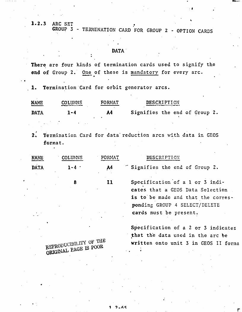
1.2.3 ARC SETGROUP 3 - TERMINATION CARD FOR GROUP 2 - OPTION CARDS
DATA'
There are four kinds of termination cards used to signify the
end of Group 2. One of these is mandatory for every arc.
1. Termination Card for orbit generator arcs.
NAME COLUMNS FORMAT DESCRIPTION
DATA 1-4 A4 Signifies the end of Group 2.
2. Termination Card for data'reduction arcs with data in GEOS
format.
NAME COLUMNS FORMAT DESCRIPTION
DATA 1-4 A4 Signifies the end of Group 2.
8 11 Specification of a 1 or 3 indi-
cates that a GEOS Data Selection
is to'be made and that the corres-
ponding GROUP 4 SELECT/DELETE
cards must be present.
Specification of a 2 or 3 indicates
that the data used in the arc be
jPRODUC1BILITY OF THE written onto unit 3 in GEOS II formaOIGINAL pAGE IS pOOR
ORGI
1 r

TERMINATION CARD FOR GROUP 2 (Cont.)
NAME COLUMNS FORMAT DESCRIPTION
9-10 12 Optional change of input unit
for GEOS data tapes. Default
is 20.
11-25 D15.8 Additional input units for GEOS26-40 D15.8 data tapes. If more than one41-56 D15.8 input unit is specified the data
will be merged in time order as
it is read.
3. Termination Card for data reduction arcs with data inGEOS-C Card Image Format, RAP Binary Format, or DODSBinary Format.
NAME COLUMNS FORMAT DESCRIPTION
DATA 1-4 A4 Signifies the end of GROUP 2.
8 Ii A value of 1 or 3** specified
here signifies that data
Selection/Deletion cards follow
for data in any of these formats.
GEOS-C Card Image Format***RAP* Binary FormatDODS Binary Format
A value of 2 or 3 indicates that
the data used in this arc be
written onto unit 3 in the same
format that it was read.
RAP Binary Format - Research and Applied Physics.Binary Format.**
See APPENDIX B.
See APPENDIX C.
1.2-66

TERMINATION CARD FOR GROUP 2 (Cont.)
NAME COLUMNS FORMAT DESCRIPTION
9-10 12 Input unit for data tape.
Default is 20 for card image
formats and 21 for binary
formats.
11-25 D15.8
Additional data tape input
26-40 D15.8 units. If more than one unit
Sis specified the data will be41-55 D15.8 merged as selected.
-4. Termination Card for data reduction arcs with data in PCE
or simulated data formats.
NAME COLUMNS FORMAT DESCRIPTION
DATA 1-4 A4 Signifies the end of Group 2.
9-10 12 The data tape input unit is
specified here. Defaults are:
20 for PCE data and
21 for simulated data.
1.2-66.1

1.2.4 Arc Set
GROUP 4 - SELECTION/DELETION CARDS
1.2.4.1 Selection of Multiple Data Forms
This Selection/Deletion option is applicable to thefollowing input data forms:
GEOS-C Card Image
RAP Binary
DODS Binary
If the data Selection/Deletion option has been specifiedon the card then at least one SELECT card and as many as 100SELECT and DELETE cards will follow the DATA card. The end of thiscard group is indicated by an ENDALL card.
The form of the SELECT card is:
Name Columns Format Description
SELECT 1-6 A6 Selects from data tape.
7 Ii Measurement type category indicator.
1 - Right Ascension (or Hour
Angle) and Declination
2 - Range or Range Difference
3 - Range Rate or Range RateDifference
4 - Altimeter
5 - Direction Cosines
6 - X-Y Angles
7 - Azimuth and Elevation Angles
1.2-67

Name Columns Format Description
8 Al Measurement Sub-Type Indicator
Sub-types vary with measurement
type cateogry and will not in general
--need to be specified. A complete
list of the categories and sub-types
is specified in Appendix C; columns
8-9 of the GEOS-C Card Image Format.
9-10 12 Measurement Modulo Number
An integer n specified here indicates
that only every nth data point from
the stations and types specified on
this card will be selected.
11-15 15 Receiving station number if data is in-either the GEOS-C format or the RAP
format.
11-16 A6 Receiving station name if data is inDODS Format.
18-24 17 Satellite ID
25-30 16 Date in form YYMDD for start of
data selection.
31-36 16 Time in form HHMMISS for start of
data selection.
37-42 16 Date in form YYMMDD for end of
data selection.
43-48 16 'Time in form HHMMSS for end ofdata selection.
1.2-67.1

1.2.4.2 SELECTION AND DELETION CARDS -- GEOS FORMAT,
If Data Selection and/or Deletion is desiredat least one and as many as 100 SELECT and/or DELETE cards
must follow the DATA card. An ENDALL card must terminate
this group of cards..
SELECT
The SELECT card is a Data Selection card for data tapesin GEOS format.
NAME COLUMNS FORMAT DESCRIPTION
SELECT 1-6 A6 Selects data from tape.
7-12 16 YYMMDD* of start time for
.data selection.
14-15. 12 Hours of start time for
- data selection.
16-19 14 Minutes and integral seconds
of start time for data selection.
20-23 14 Decimal seconds of starttime for data selection.
25-30 16 YYMMDD of stop time.
32-33 12 Hours of stop time.
34-37 14 Minutes and integral seconds
of stop time.
38-41 14 Decimal seconds of stop .5me.
1.2-68

SELECTION/DELETION CARDS (Cont.)
NAME COLUMNS FORMAT DESCRIPTION
-43-47 I5 Station number; all stations
if not specified.
49 11 Measurement type; all types
if not. specified.
50-51 I2 An integer n specified here
indicates that only every
nth data point from the sta-
tions and types specified on this
this card will be selected.
/ These columns have no meaning
for the DELETE card.
This card is optional.
*If start and stop times are not specified, these times are
assumed to be the start and stop times of the data on the
tape.
1.2-69

DELETE.
---The DELETE card is a Data. Deletion Card for data tapes
--in GEOS format.
NAME COLUMNS FORMAT DESCRIPTION
DELETE 1-6 A6 Same format as SELECT except
that all times, types, and
stations refer to data del-
etion rather than data selection.
This card is Optional.
1.2-70

ENDALL,
-NAM COLUMNS FORMAT DESCRIPTION
ENDALL 1-6 A6 Specifies end of data selection
and/or deletion cards.
This card is Mandatory when SELECTION OR DELETION cards fordata tapes in GEOS format are used.
1.2-71

1.3 FORMAT SPECIFICATION
Key -n- m = integer numbers
b - a blank space
FORMAT CODE
In Integral.numbers right-adjusted in a
field of n columns.
Example: 25 in an 13 format: b25
Fn.m Digits with a decimal point anywhere
in a field of n columns; digits punched
without a decimal point assume the
point m places from the right.
Example: 30.1 in an F5.2 format:
b30.1 or 30.1b or b301b
Dn.m Digits with a decimal point anywhere in
a field of n columns; digits right
justified in a field of n columns with
an exponent of the form D+XX, where XX
is the power of 10. If there is no
decimal point, assume the point m placed
to the left of the D.
Example: 30.1 in a D8.S format:
b30.1bbb or 30.1D+00 or 301.D-01
En.m Same as Dn.m except that the exponent
when used, takes the form E+XX.
An n-alphanumeric characters.
1.3-1

2.0 GEODYN JOB CONTROL LANGUAGE AND HARDWARE AND SOFT-WARE RESTRICTIONS
2.1 Job Control Language (JCL)
Certain JCL cards are necessary for all GEODYN runs.
These cards are:
* The EXEC card specifying the name of the pro-
gram to be executed,
* The STEPLIB card specifying the program library
in which the GEODYN load module is stored, and
-* The DD cards specifying the characteristics of
the FORTRAN Logical Units used by GEODYN.
2.0-1

.f
DETERMINATION OF GEODYN CORE REQUIREMENTS
-Since GEODYN's core storage requirements ,re dynamic,
-the following equations -should be-used to compute the REGION
to be specified on the EXEC statement.
REGION = Bytes + 3301024
Bytes = 226 + 46N 1 + 146N 2 + 224N 3 (N2 + N3 ) + 96N 3N13
4 150N3 + 214N 4 + 4N5 + 136N 6 + 16N 7 +8N 6 N8 + 16N8
+ 8N + 56NN + 40N 1 2 + 18N1 3 + 28N 1 5 + 4N2 5 + N19 + N21
where
N1 = maximum number of biases in any one arc.
N2 = number of tracking stations used.
N3 = maximum number of satellites in any one arc.
N4 = number of tracking stations estimated.
N6 = number of surface densities.
N7 = . number of surface densities estimated.
N8 = number of constraint equations for surface
densities.
N8 = ND (ND + 2) where ND is the maximum degree
of geopotential for constraint equations as
specified on the TOLS card in COMMON SET,
GROUP 2 - OPTIONS CARDS.
N9 = number of solid earth tides coefficients
estimated (not a current capability).
N1 0 = number of ;eopotential coefficients estimated
as common parameters.
N11 = N1 0 + N16
N1 2 = N7 + N - N 8
N1 3 = maximum number of equations which must be
-integrated in any one arc. (=N3 + Maximum
of (NeqI + Neq2))
N1 4 number of master tracking stations estimated.
14

N1 5 = maximum" number of parameters estimated in any
one arc plus N1 7 (number of common parameters
.Le.stimated).
N16 = maximum number of geopotential coefficients
estimated as arc parameters in any one arc.
N17 = N 1 .+ N14 + N12
N18 " greatest number of two station (i.e., 3-way
average range rate or VLBI measurement) base-
lines associated with a single station.
N1 9 = (N2 + N3) (N3) (N1 8) (23)
N2 0 = maximum number of electronic biases in a
single arc.
N2 1 = (2) (4N15 + 13) (N19)
N5 = maximum for any arc of the following
N5 = NINT1 + NINT2
NINTi = 12 + 12 Neqi + 6 (OEi - 1) Ii
+ 6 (0i 1) Vi Neqi - (I - 1)(1 +Neqi )
where
OEi = integration order for the equations of motion
of the ith satellite.
OVi = integrtion order for the variation equations
of the ith satellite.
IVi = 1 if fixed step integration is used for
ith satellite.
2 if variable step integration is used for
i satellite.
Neqi = number of force model equations which must be
estimated for the ith satellite.
* 'orbital elements are six.equations.
* drag, drag rate, and solar radiation areone equation each.
* geopotential coefficients are one equation each.
* one equation for each N12 ,= 0 for orbit generator run.
2.0-3

August' 11, 1973
GEODYN JOC CONTRCL LANGUAGE
FOR T.HE 3CC/S5
.f/** 0 JO *o**/GEODYN EXE PGM=ZCTVMGDh.9EGICN=380K
"STLPLI13 Do r.SN=C--.'IDGILi IP*CECSTRDISP=SliR"FTf*IF:Ill Do Ds,,4=Gq *ZCTVtJ.oEF-HE..X.DLSP=S'iL*DCP=DUFNC:=!*/FT02Fr)l)l DC DSN=PCE3S*E;CE!=(i- ECFt.F=F*BLKSIZ :-'=:!52t)*[3urNC=I)oUtilT=23149-
" VOL=SER=CODSoa*EPACE-:=(T;;Kg32..,4).Di -zP=Stir-.,e/FTfjF^*'I DO Ut4lT=P4': 1-9.CCF=(RECFxt=Vf3:;oL,-ZECL=Iri4ocLKSIZE=I")44)o
LA.iEL'=(*ELP)tVJL=SER=GLICATA"FTt4F,7-'%I DO DSN=PC LSDCE=(;:ECFM=F.t3LK.*7:IZ: =:!52-34[!UFNC=I)IU441T=23141
VGL=SE:Z=C0:)302* SPACE=( T!;Kt 221 ) DI EP=SHF-*f;f FT't E F C I D C DONAPAL-CATA5*#lFTD6F-t-')I DO SYSOUT=A.DCS=(SECF9=VDA*LF-ECL=337sl3LKSIZE=72Cz5)o" SPACE=(CYL.20)
WFT07Ft'll 00 SYSOUT=B*DCB=(r-ECFP=FBvLI;ECL=B'.,eLKSIZE=3:;C,)*" SPACE=( 8!:V. lj, )"FTOLEFC03 Do SYSOUT=A*DCE=(AECFPI=VBA oL 9C-CL=I:!7*ELIcS]Z-=72f5)9#*/ SPACE=(CYL.I:.)
-"FTllSF-3')I OC SYSOUT=AoDce=(FECFP=VBA*Lr-SCL=137,ELKSIZE=7265)9
SPACE=(CVL.I0)"FTIOFCr-I Do UNIT=OISKoDCE=(RECFM=FE-iLrtECL=46teLr.sIZE=463),e" SPACE=(TRK*3) I
"FTIIFC-01 Do UNIT=DISK.DCE=(RECFP.=VeS.LPECL=deeLKSIZE=72'94)9" SPACE=(CYL.3)
"FTj2F*''ll Do UIN IT= 2314. DCB= (OLKSI ZE =1232 t3UFNC=l ) SPACE= (CYL. 20)"FTl?FPll DO U,41T=DISK.DCE=(PECFM=VS.PLKSIZL:=16.32,BUFf4C=I)tfi SPACF=(CYL',:0)
"FT14F(.rl DOSPACE=(CYL.5)
Z/FTISF ,,:ll DO UN IT=Z314. DCE= (BLKSI ZE= 1 V% *BUFNO=l ).SPACE= (CYL. 1.)"Ftlcr,,- l DO U.41T=2314,DCE=(RECFM=VB .LPECL=1804*13LKSIZE=18')O*
.- ,#/ -8,LFN3=I)*SPACE=(CYL.5)
*"FT17F0')I DO UNIT=DISK.DCE=(RECFf4=VBS.LrECL=*.Of)*eLKSIZE=3521SPACE= (CYL.:! I.0 ISP=( . PAS!) Dc.*,=rS I VGATA
"FTIEF, Ql DO UNIT=DIEK.DCe=(RECr-m=FB.L;;F*.CL=eC*eLKSIZE=1(3tlOo3UFNO=2)." Sc)ACE=(C*YL.I).DISP=C.PASS).DSN=F-GFNCTRK
"FT19FOC.1 OD U.NIT=DISK.DCE=(RECFm=VDS.L;ZE-CL=*,!2e8LKSIZE:=28C,4*eUFNO=1)9SPACE=(*CYLtl).DISP=(*PASE)oOS.'-4=fGEORGE
dlofFT2fiFt%0I 00 UtIIT=24 -:j-4.CCE=(FECFt-I=FLI*LAECL=51*eLKSIZE=800^*.CEN=3),
lel LADV-.L=(.E!LP).VUL=SER=GECSDATA41,eFT21FCll Do UNIT=?4 ) -9.CCE=(RECFM=IvCS.LPECL=I.',4.eLKSIZE=IP)44)9of/ LADEL=(9E3LP)s%4CL=SEc4=DCCSDAIA
"FT22F?%0l OC UNIT=Ci!:K.C)CE=(PECFM=VS.P-LKSIZE=2EO4,oBUFNO=I)o
Zr SPACE=(2 2C4.5G) to ISP=( 9 PASS) vDSN=ECrBl
,elFTZCF01 I CD U,'41T=2314.CCE=(F;C-CF.,,4=UT*E-LK.SIZE=21;152)9401/ SPACE=( 29176.I-)"FT71Fnrl Do UNIT=2,%G')-4.CCE=(RECFP61=94eS.Lr ECL=8:1690LKSIZE=S)20,.,fl DEN=31*LA[3 - L=(I.BLP),VCL=SEI;=B.*4AT-X -tv
,f.0SYSLDU-%lF DO SYS0UT=A*SPACE=(CYLoI) OV
4f##DATA5 DC V oo?
.GEOOYN SETUP GOES HERE* NG
0 IG
2.0-4-

THE FO!-LOw!NG JCL CA!'DS ArENz-'F FCQTs4= '%60z1 IN PLA'CE Cc THN-
SS~T!PL!B f, FTG17':Cl CACOS
"STEPL II CC~, =.CV4COLdZ=p
REPRODUCTILIy OF THE~
ORGIGAL 'PAGE IS POOR
* 2.0-S

Name Columns Format Description
49-50 F2.2 Relative Humidity*at Receiving
Station (subsatellite point for
altimeter)
51-53 13 Surface pressure in mm of Hg at
Receiving Station (subsatellite
point for altimeter).
54-56 13 Surface temperature in OC at
Receiving Station (subsatellite
point for altimeter).
57-61 I5 Second station number if data is ineither the GEOS-C format or theRAP format.
Transmitter for average range rate
'Reference for VLBI
Relay for SST
57-62 A6 'Second station name if data is
in DODS format.
Transmitter for average range rate
Reference for VLBI
Relay for SST
64-70 17 Satellite ID for Relay Satellite in SST
71-72 F2.2 Relative Humidity*associated with
second station.
73-75 13 Surface pressure in mm of Hg at
second station.
76-7.8 13 Surface temperature in *C at •
second station.REPRODUCIBILITY OF THEORIGINAL PAGE IS POOR
qOTE: *Relative Humidity - If 40% input 40If 100% input 1.
1.2-67.2

A.?1st 11, 1.973
JCL FOR GEODYN UNIT 1 WHEN CENTERCARD IS USED
/FTfIF) 1 OD UNIT=24 .- -4,CCE=(RECFM= ES;LRECL=91 eBLKSIZE=72949// DEN=3).LA8ELL=( ,NL) VCL=SER=XXXX
* 2.0-5.?, o.

GEODYN FORTRAN LOGICAL UNITS
UNIT SPACE PURPOSE " DESCRIPTION
1 Ephemeris GEODYN uses the JPL ephemeris
-for the moon, sun, Venus,
Mars, Jupiter, and Saturn.
Necessary in all runs
2 DODS Data. On 360/95 only. See AppendixBase A
Observation File
3 Data Tape See Arc Set,Group 3 - Termination
Output Card-of Group 2.
4 DODS Data On 360/95 only. See AppendixBase. A
Element File.
5 Card Input System card input unit; used
for GEODYN Input Cards.
6 (CYL,(10,1)) Printer' System printer output unit.
10 cylinders of primary and
15 cylinders of secondary
space are allocated. 1REPRODUCIBILITY OF THEORIGINAL PAGE IS POOR cylinder will hold 1060
full lines of print.
.7 (CYL,1) Punched GEODYN punches updated para-
Output meter values. The one cylinder
of primary space which is
allocated will hold 1800
punched cards.
8 (CYL,10) Printer Used for satellite Cartesian
ephemeris printout during data
reduction runs.
2.0-6

UNIT SPACE PURPOSE DESCRIPTI fO
9 (CYL,10) Printer --.Used for satellite Keplerian
..ephcmeris printout.
10 (TRK,3) Scratch Necessary for all data reduction.. . runs. ;Allocated primary space
. " . • of 3 tracks will hold 495records. GEODYN writes a max-
" imum of 600 records.
11 (CYL,3) Scratch Necessary for all data reductionruns. Allocated primary spaceof 3, cylinders will hold F0360
-observation data records. Suf-ficient space for the maxi.mu'number of data records in asingle arc must be allocated.
12 (CYL,20) Scratch Necessary for all data reducticnruns. 20 cylindcrs of prir:nr
REPRODUCIBILITY OF THEORIGINAL PAGE IS POOR space are allocated.
of space will hold 1720 ob-
servation data records.
13 (CYL,10) Scratch Necessary for all runs. 10cylinders of primary space
S . are allocated. 1 cylinderS. of space will hold 80 records.
Each arc writes five 2'ecords.
14 (CYL,5) Scratch Necessar), for all runs. 5cylinders of primary space'are allocated. 1 cylinderof space will hold SO reco .The number of records per arcis variable.
-r

UNIT SPACE PURPOSE DESCRIPTION
15 (CYL,2) Scratch Necessary for all runs. 2
S--cylinders .of primary space
-.are allocated. 1 cylinder
of space will hold 80 records.
The number of records per
arc is variable.
16 (CYL',5) Scratch Necessary for all runs. 5
cylinders of primary space
are allocated. 1 cylinder
of space will hold 80 records.
The number of records per
arc is variable.
17 Simulated GEODYN can simulate trackingData data or PCE data on option.
Output
18 Groundtrack If a groundtrack tape is
-requested, JCL will be
required for unit 18.
19 Binary A DD card is necessary forResidual each file to be written.Tape
GEODYN writes one file for
REPRQDUUCWILITY OF THE each Binary Residual tapeORIGINAL PAGE IS POOR
requested.
20 Data Tape GEODYN default unit for inputInput data tapes in GEOS format
or PCE format.
21 Data Tape GEODYN default unit for inputInput data tapes in DODS format or
Simulated Data format.
2.0-8
PF

.
August 11, 1973
UNIT SPACE PURPOSE . DESCRIPTION
22 ORB1 Tape A DD card is necessary for each
file to be written. GEODYN
writes one file for each ORB1
tape requested by an ORB1 card.
30 (29176, Partitioned Necessary only for those runs10) B-Matrix where the BPART option is used.
Scratch Space allocated is sufficient
File for 10 records to be written.
B-Matrix size in bytes must be
less than the number of allocated
recrods times 29176.
71 B-Matrix A DD card is necessary for eachtape file to be written. GEODYN writes
one file for each arc exercisingthe BMATRX -.option card.
23-29 Option I/O These units are not regularly1-70. units used by GEODYN and may be used72-99 as a.dditional data tape input
files or as RV tape output files.
REPRODUCIBILITY OF THORIGINAL PAGE IS POOR
2.0-9

Augus~t ll. 1973
S-TME -GEOOYN *0VERL-AY -STRUCTURE IS
OVERLAY ESTIM
INSERT %:TIMIESTIPI.PGSVEL
OVERLAY ESTUA
INSERT FiFOR'41 ULFURM BECLVE *BREAD, URI TE
OVERLAY JACCH1A(F'EGION)INSERT DENSTY
OVERLAY J71J65
INSERT D(;E* OVERLAY J71J65
INSERT DE50
-OVERLAY J71J65INSERT 071
OVERLAY PRIIME(REGION)
INSERT ACFLUXJANTHG.-ALIST.R#'FTMCD.FLUXMsFLUXS.CMOCELOIMELINSERCT INTFLXtF.UXAP
OVERLAY P~l!"EINSE!!T OJASINpTIPa4-kAR;C.FRNTPRCCEFLSIGBLKINSERT SRFB3LKPO--t,-EIASt'CSTARFARTD3
OVEPLAY CATAREAD
-INSERT DC0,DDATQS - ,CELI',OCDOAT
OVERLAY D41AREACo INSERT GFOSFC
OVERLAY SAICLCS
INSERT SATCLC
OVERLAY SATCLCSINSERT SATCL2 ,SATC21 .SAIC22
GVwT.LAY 041ARZAC
INSERT PCERDOVERLAY DATAREAD* INSERI SIAD
* OVERLAY PR IME* INSERT NCN'AMIE,CHARLYCBRCWNSOUJANT.SOANT.,CSTIET.XYZMC"4GP.DVPGDLK
INSERT PRCIs;OZ;9CC D 9C1t L DT ~ A D 'A.C:G
INSERT TkPLS!PYCCt'DR'XZU.-T7G;PIG-qtINSERT STAZF1,STAIF,STATT;UEP.*'TPU -:!VVALVL:VAL~eVMAT
INSERT STAIF2,F.F1,OBSD)CT.CEStTI,O::E"IT.O;;31T'INSIERI PRECCTP~lrUC& ,*.ESF:AF.SPR1,CCri ECLCC.A0J
INSERT SLDENSLR.4.vPCEh.FDEN2
INSERT TWOSTA 1T%3ST.-., CMPUPZ)OWN%*ESCOwF.3SCM'.
INSEPTr flEFlON.RFJL'tlJ
OVERLAY SECCNDINSERT CCI.AkSTANPA;CFAPSTAPOSINSERT AREASsCELTA.INCEK~T
* CVEF.LAY SECOND.
INSERT EC:ZAVCR8'TAP.SIJNGR.;V.TI0AL.PEFCCr%
INSERT CCEF*C0MINThZPoI1E~rFCSLlI
OVERLAY THIPO
INSERT START 1P 0BLTOP-HOVERLAY TH IPD PQDtJOBITYp l
INSERT COCO ORIGINAL PAGE IS POOROVERLAY THIRD
INSERT AITENA .bELAY.L)ILFNDCFPLR. ICNREF.FCLE
OVERLAY THIPO
* INSERT REARG
* OVERLAY THIRD
Z.0-10

Agust 11, 1973
INSERT TYPORB9GEODYNOVEFLAY THIFD
IRSCRT GEGIDH,'AGPOTOVERLAY SECCND
INSERT UPCATEOVERL.AY EXT7A(REGION)
INSEPT ErOR
OVERLAY EXTrA
INSERT 0I01
OVEFLAY EXTPA
INSERT HEADER-OVIVFLAY E-KTRA
INSfRT BMTwRT
REPRODUCIMLITY OF THEORIGINAL PAGE IS POOR
2.0-10.1-

2.2 Hardware and Software Restrictions
Normal operation of GEODYN requires a large scale
'-IBM 360 Computer with 500K bytes of user accessable core,
one 231.4 direct access disk unit, four 9 track tape drives,
one 7 track tape drive, one high speed cord reader, and one
high speed printer. For some applications, GEODYN can
operate with only one 9 track tape drive and no 7 track
tape drive.
The current GEODYN program is executable under
versions 14, 16, and, 18 of the IBM 360 operating system.
The compilation of GEODYN requires an IBM FORTRAN IV
-Level G compiler and for more efficient operation also
an IBM FORTRAN IV Level H compiler with level 2 optimization.
GEODYN contains four software restrictions. These
restrictions and the subroutines affected are:
1. Time difference tables must be kept up to date
in subroutine TDIF.
2. Polar motion data tables should be kept up to
date in subroutine POLE.
3. Solar and Geomagnetic flux tables should be
kept up to date in subroutines FLUXN and FLUXS.
4.. Tables of the right ascension of Greenwich in
blockdata subroutine CONSTS must be kept up to
date.
There are no GEODYN hardware restrictions.
REPRODUCIBILITY OF THE'ORIGINAL PAGE IS POOR
2.0-11

3.0 GEODYN JOB SUBMITTAL
--To prepare a GEODYN deck for job submittal the following
_procedure is recommended:
1. Define:the problem to be solved.
2. Prepare a deck of the necessary GEODYN Input
Cards.
3.. Prepare the JCL necessary for the desired GEODYN
execution.
4. Assemble the deck and submit to the computer.
3.1 Preparing the necessary GEODYN Input Cards.
1. Determine those-parameters of the problem
definition which must be defined by COMMON
SET cards (i.e., gravity model modification ,
lunar and/or solar gravity modification, geo-
potential coefficient recovery, station estimation
parameters,-modifications to the atmospheric
density model, and modification to earth constants.)
2. Determine which COMMON SET cards are necessary
and prepare these cards.
3. Determine how many arcs will be required and what
parameters must be defined by each arc.
4. Determine which ARC SET cards are necessary
for each arc and prepare these cards.
5. Order the cards prepared in steps 2 and 4 so that
they conform to the four groups within each
set and place these sets in the proper order
as follows:
3.0-1

COMMON SET - -Run description (Group 1)
COMMON SET - Option cards (Group 2)
COMMON SET - Station position cards (Group 3)
----COMMON SET - -Termination -card- (Group 4)
ARC SET - Arc description (Group 1) for ARC 1
ARC SET - Option cards (Group 2) for ARC 1
ARC SET - Termination card for Group 2 (Group 3)for ARC 1
ARC SET - Selection/deletion cards (Group 4) forARC 1
ARC SET - Arc description (Group 1) for last arc
ARC SET - Option cards (Group 2) for last arc
* ARC SET - Termination card for Group 2 (Group 3)for last arc
ARC SET - Selection/deletion cards (Group 4) forlast arc
NOTES: Always required for orbit generator mode is the ORBIT
card.
Usually required for orbit generator runs also is an
OUTPUT card.
STAEST, CORREL, BIAS, RESID, CULL, EDIT, PREPRO, SIGIMA,
VARCOV, and ARC SET, GROUP 4 - SELECTION/DELETION CARDS
should not be used in orbit generator runs.
An ORBIT card may not be used in a data reduction run
under any circumstances.
A problem may consist of any combination of arcs in
orbit generator mode and/or in data reduction mode.
If any arcs are defined a 3eing in orbit generator
mode, the maximum number oi outer iterations must beone, and no common -irameter estimatiozn may be requested. Acommon parameter e: .mation prcblem must define all arcs asbeing in data reduction mode.
3.0-2

3.2 Preparing the Necessary JCL Cards.
1. Determine which JCL cards are always necessary
for a GEODYN run.
2. Determine which JCL cards are required for the
.specific mode of operation for the GEODYN run.
3. Determine what additional JCL cards are necessary
for special output requests.
4. Combine all necessary JCL cards into their proper
order as specified in section 2.0.
3.3. GEODYN Deck Assembly and Job Submittal.
1. Place the GEODYN Input Card deck into the JCL
deck after the DATAS DD card and follow with a
delimeter card.
'2. Submit the job to the computer with the proper job
identification slip.
3.0-3

4.0 GEODYN EXAMPLE JOBS
On the following pages is a comprehensive set of
.-GEODYN example job setups. -:GEODYN Example Jobs 1, 2, and
3 include the setup .examples for the GEORGE, DELTA, ORB1
Conversion, and GROUNDTRACK programs. By combining the
execution of the GEODYN Analyses and Graphics Support
Programs with GEODYN execution, the most common usage
of the support programs is demonstrated.
4.0-1

4.1 Example One
This sample run is a 4 arc station estimation run
using station constraints. Included are two 2 day GEOS-I
arcs and two 2 day GEOS-II arcs. -GRARR biases and timing
errors are estimated. Following the GEODYN execution is
a GROUNDTRACK execution for arc 4.
This job was run on.the 360/91 and requires core
-and time as follows:
CORE CPU I/O
GEODYN step 394K 6.23 0,96
GROUNDTRACK step 376K 0.03m 0.02m
4.0-2

March 1, 10-73
GEODYN LXA'MiLE JfOB CNE
/ftGvnr'a CEC 93GV ZCTV"GIDM*PEG1 ON=3V0KF/STEDLJIB r.0 C~~t=,2 Z T ,AL A-L t.'-~.=~
#*tFT05root E)'_ r- '-! E D A T A.I/FT05 F10 1 D 0 SYSCVT=A.CCC!=(PECFMi=VpAL*ECL=337pLKS17(?726S).
S/ SACE=( CYL, 20)
I/t 07S c31 ) r-=C*A00,1
*//FTO~tFOOj 0") SYS-UT=%.CCEC(:EVL.=ALRECL137,r1LSZ!-'72I5),1/ SZIACC=(CYL, 10)/FTO:F.JOI DO SYI.tCUT=ACC(2=(RLCrF'MV~tALRCL37,P.LY.SIZ==72( ),dlS ACE=(C~YL.10
//S ACE=(TP.K.3)//IFTIIFoO1 D)D UN4=IYDE=R-F.=ESLr:t=8ILSZ-79).Of S:IACF=(CYL.3)/IFT12FOO1 DD NIT2,1 -C= !I lZE72_2B=4= SAE(Y#0
//S'ACE=(CY'L, 10)/f/FTI',Pool DD) U.qTDnCI(--:C-z-S-L4I
/1S>ACE=(CYL.5)//JFT15F00l 03
/f/FT ?Fo0l DO0~ UN~ IT=O! St,. CI=(; P-C==F ,L:ZECL=30."3L),! 7':=1 00. 3uref:o=,,
/G.rT2?0Foo1 -D UtrJT2400-9.LclqrL=.c .'L" VC'L-FP=AT/1
li/ cn r. cr-,(IE FVP,. UCL= r0, ;LK S I ZL 32 00 0) .'.NI
//G0. T 2 (rC 0 1 -C) UNIT=2 -= i' -L O -D.Of )Cl= (PZCFFnS LECL=110. L KS) ZE=,0GO.oN=3)//dSYS*-JC)Uklp DD SYSqUT=A.SPACF=C ZYL. I).*/DATk5 VDSTAT 11N ESTIM TfIAON USING 2 GFOS-11 ?-DAY AQ4CS AND2 GE0S-1 2-OAY APCS $1171 STATIONr CC, %Tr.-AtNTS ANDSOLVING F0: G;A:4R EUIASLS AND Titl1NG URRORSSTAI ST 1037. S. 5 50,STAEST 1 126. 5 1 5. 50; 1037.STAFST 1042* Se *59 Soo 1037.STAU ST 1021. .5 50.
ST AS 05n lPC!IN'10 21 3"54 4.7672 25?54 A i61 30 -53.6931FTIAYRI1022 P632S3. 1400 27-A F 4,1600 -42.000 tpR)Tojjj OTH
ISITA910aiit:s3 6537136, 26slc53.6 6 17 713.no QIRIGINAL PAGE JS POORu1'U0JAV 1 1:3) 351 ./ 7. 1.937 2 4' 5,3 . 91 C I e6*
1 mrg F 103? fa74-s', -1c). P 6460 30 71 C, . .14 00 45.000IC UL. I' 10 33 01. f, S17 ' -- 511 212 Q'6.7652 156. 367aI F GW 10:34 4C 12 1 .'.10 u 262591 '. 50 72 203o.162
1T.1 1 1410 37 ,'* 1 .1.1.Yc, 6 277 741.1600 !4' p3'10I40fiL 10"333S 32. 6-i17 1 4C571 [email protected],0O1 94 9* 57,3

tcCSala 1" 512 7.2" 27 7.C, :c I ff..-c c..f63SIT ?4A4I 3-1 .12.1 5 471' =s.5;7 " 135 "777-CATA 23
&oC 1-COS-1 iG A-r -11D OT!C-CL CATAVA'= C -- 1".5 Tk,. =AY 4' .
VeC2!?.tC:CuCt: 5' 112!'3 1 2 . . ; e 37716,3*r5..:2 f*.,5'. 3j -6 ) *)* , J73e3
-6374.47371 11z-M'1 C 37- :~1 -7- 3565 619.-Jj; J iI17-3
SAT 1 1.22 1/72*PFEP911 $u* 1.SIG-a - . 2.0 O
SIG vA e to*SIGiA 3 .12 C
SIAS 1126 0. 1Go 2*
elAS 1126 C. Cot 3o
CA A 120
SFL-'CT 66 32 CC32
ENCALLAPC 2
r!5-I .OPTICAL )3ATA
NOVq"42=" 24.s 65 TwO DAY AcC£51124
-3e371c7.-(-4:523 -E4547-33.236721a5 277:51.5345.61 7 3
,1CA2615533 1 1 -3 -- 2291 o275116r.1:32 -647e.2 31)1 J7137,
SAT I 1.23 172.SIG"A Is 210
SIG A 4 2.CATA 120
SCLECTe5112a 651126
ENCALLAQC 3
GEOS- I GqA=R DATAFEBRUtRY 2'.1h68 TWO CAY ARC
tC225C8C225 5 2
-C*?725697E35484C40 C7 C.226d4 7 6633 7 5679'70 C7 -0.71164CjJ 1E773)C0 37--0. 1C54Ie54237555?D C4 C.64e2624;-?2"~74f4 CA 0.J.l21a ?o3607-7 750 04SAT 1 1.23 211. E31
SIGMA 2. 10o
SIGMA ". 12.*e BIAS 1126 0* 10. 2.
BIAS 1126 G. Cs.10 3.eIAS 1128 0. CeoCSFIAS 1122 0. 0*005
CATA 125
SELECT69 C225 feC22 7 2 5SELECT 6 C225 6eC227 3 6
NcALL ~PRQyDUGIBILITY OF THEAcC 4PAGE IS POORGEOS--II OPTICAL DATA PAGE IS POORMAY 22.146 TJWO AY ARC
e0522E0522 5 2
.4217217.-;1518S034 20471f3.062645225 -60b36J3. 7_720c,-3326.C123C774676C -!1e7.73 5742C~2!4 -37 ,. ±6314. )C5757
SAT 1 1.23 211.831
4.0-4
Fl

.SIGMA 2--0
OUTPUT I
ICATA 1e 6
STLcCT6t:9iZ 6efS24F*40~ALL-
/!/ EXC L N;-#,. IN .=!C
INCLUUC LCAL!7ZCJ,,St;L)I.4CLUC' LCCL-(ZCGkY3IrJTPY 1'.A!N
&#,rGr%*cTll P'.L IVC 0' Sr4=r&G--.C1RI' *VISF-=(CL:3*0-LETE)
5t~rSk*NICZ- Zt2 7o2752 277 7411 eIf.. )41;9033
* PLOTS
T IME t!:C522. GPC524oLslWPLTCAT40LA1ST
p~pBODIJCIBIL1Ty OF THE1~
oRXGINL WAE 15 POO)R

4.2 Example Two
-This sample run is a five--and -one half.day GEOS-II
data reduction run which estimates 2 pairs of resonant
geopotential coefficients and a solar radiation parameter.
Following the GEODYN execution is a GEORGE execution
which computes ROSRAN range zero set biases and timing
errors.
This job was run on the 360/91, and requires core
and time as follows:
CORE CPU I/O
GEODYN step 338K 4.16m 0.83m
GEORGE step 326K 0.11m 0.06m
REPRODUCmUILIT OF THEORIGINAL PAGE IS POOR
4.0-6

0MbrcIi 1 1.973
ion.
ft GE 0DY 14 EX-TC PGI= ZCTV'1GDPJ 01-"'i ON,3'O(/fSTEPL~n VD. tSN=*2.ZCTV%.Ll~frILI9.rlSP=SHR
//FTOSFuoo V00 C!AMl~w2.ZTVAIEI *ADS=4P)C=iJN=ffFTO5FUo1 DU (tt1*1E=)T
c-:)-ACF=(CyL.20)/fFTO7FOOI 30 SY.IOVTIJvCC2!CRECFM=F.LC=fl0.ILKSIZL.fl00)9
1/S>ACV=('00.100)* /FTO3r-ool (r' SYrtJT=A0CO=(E.IF-VrOAL.-ir-CL=37,LKSZ.7265).
Ii' S'PACE=(CYL,10)tfFT09FOQ3 (V0 SYOTADE('E-..=F.ALEL27VKIC70)
Off S~bACC=(CYL. 10)//FT13rool -)D UNIT=OISK.C'CR(r-ECFrFBLECL4.,nLKS12E'
4 60)odlS=ACti-(TPK.3)
tf~t ot~iD: UIIT=DISKDCC= CF?AVSLRECL--68.t1ILKSI1:-"72 9 4 )v
d'S ACC>1CYL.,3)/IFT lSUO01 CID UNIT=2314.D-C =(c L'KS17 17230,flur. 4NO=) .SDCE=(CYL.2)
Z/FTI3VOO1 DOfl. SflA'CE=(CYL 1)ID5~IASS~C../fFT24F3)0I M) D
//SYSU%*' :'D SYS0UT-=AeSPAC:-:(:YLs1)//DATI.5 DOA5 1-2 L'AY CS-1I DA-TA PEDVCTION UUN *d!T1 THE rSTYDAAT!ON1Or 2 DIAIrS OF~ c.'LSCJANT CL~f-.FjCI ENTS AND) A SULAP PADI ATI ON PA.PAPAFTERF,1LLnO1D. B3Y A G.IOrPG!: RUN C0O'jUTIt.G f-OQ5-A% GRAr.P TIMAING Et'kOPSMtCorp' 131 z 0.5 A.05 4-IPECUt. 1 413 01;5OS 3DATA 2
DAT A P E 0VCT 1ONG!EOS-1 I GRAIPR DATA 0FEM5UAV.Y 21, 1965 5 1/2 DAY ARC69102216e0221 5 21075)413.141 164078 -75464F.3oi024558 -001650* 477posiva1-204. MZO1n52,44212 0 2 4 2SS*19507QO022221 -6923*057?7'610592SIGMA 2. 10.SIGM4A -30 12.SfL RA:)1 .6 .1 RODUCI9nVOUT~ -1 PAG_ F TSAT 1 0.23 213*V31 ORGNL *G
DATA ISLCCTfjt'0?2I 0000 60,0226 1?.00 20
f/Lil( YL 1r DD

INCLUOE Lr "L IJ(zrC'L0,r)INCLUDE L.1.'I -( ZC RG1Y:')* £NTFY M-4 I/GO*.F'T:50o1 l L' Sr, e : O oj-," Cc C(:CL ,.'L- 1-)
//GO DA TA DO
FANGE ROSRAPLOTQATA
LAST
REPRODUCIBILITY OF THE
ORIGINAL PAGE IS POOR
4.0-8

4.3 Example Three
a) Arc 1 is in orbit generator mode and uses converged
double precision elements to generate an ORB1 tape.
b) Arc 2 is in data reduction mode and uses the same
starting elements as arc 1 and the same data period
that was used to obtain the arc 1 elements. Arc 2
uses a truncated gravity model to reduce the elements.
An ORB1 tape is also generated by arc 2.
c) A DELTA execution follows the GEODYN execution and
computes and plots orbit differences from the two
ORB1 tapes.
d) An execution of the ORB1 Conversion program follows
the DELTA execution. The ORB1 tape written in
arc 1 is converted to a 7 track, IBM 7094, single
precision, binary QRB1 tape.
This job was run on the 360/91 and requires core and
time as follows:
CORE CPU I/O
GEODYN step 348K 2.36m 0.46m
DELTA step 200K 0.04m 0.03m
ORB1 CONVERSION step 154K 0.29s 0.09m
4.0-9
1W

- ~~march I~ ~
* IEPRODUCIBILITY~oF *THEI- ORIGINAL PAGI IS' POOR
6G(IDYN F XAM4PLE jOal THREE
/t 9/. JOE-.t/*GEO)3Y* CXC PMZCTV'.C?4,rST0N=3 OKC
I /STCEL! lc) VDCSNGI.GIDI4P. 'Tr.9tSPS'r/FITOir--)01l SMG I . ZC 7Vpj.!:2NEA-,LI ,r= *RDCs=lP'FNo I
//F*rTosrFOoi !)OJAMr=ATA5//FT05F*00l DO SYSUUTA-,CCP=(:'ECFIM=VP'A.LLICL=17,E.LK-S17E[- 7 2CS)i
/ S2ACl:=(CyL,20)I /r-To?Froo 00 SYU=tC=:E-MFJRC~oSKIEC0)It/ S2ACCF(AO0,IO0)tiFTo~raoi OD SY-rU=*C3(ZIF.=I~~lC=3..KIZ-76~~/1 S-*ACE=CCYL, 10)
//T0:;1 D SYSCUTACCr-=ZCCFI-'VRALRECL=137s.LKSIZ -72' S)Ij/ SOACr-( CYL. 10)
" / S2ACE=(TrPY,3)I/FTlIFOOl DD JIT=ISK,C=CrCFLVSLPECL=!1qPLrS17E=72914 ).
//SOACE:(.CYL,3)e/rrT2rooi -)0 U~JT=231I4.rCc~tr'LtSI7r-=232.Il~r?:3=1) .5PACr=(CYLs2O)#/FTIl3F001 :)D~1~I~D3C'Z~S"K1Z= 3 P'0)dI SDAC=( CYLs 10
I/ Sts ACE - (C YL ,15)
1 F T 5 V0C~ I % = I f, C C r ! S ! 2!L L PA r Kr!E V I2
d/ UJ~l Sl3)'ACF=(CYLv 5
/f/FT2OFOOI -')
//JFT2rOoI CDO UN RT=U-I :.rci]Uc':CF.=VS.L-LKSI ZE=2'30 .Rlk B No=I 3
//*SY SUDJ D D SY SO UT= ,. SPACE=(Y L GI//L)I1A5 DD
*A TbVU AR:C UN FO)LLOWED flY 0!:LTt AND 01131 COrZVEUSIONARC I IS AN OWt3G;rN USI NG CGN'VrPnGEf EL!:kl.NT.-ARC 2 1IS A DATA REDUCT 1014 0)Vc TttIE SAEI= P=ERiOD Ml~ TFi A TR1J::CATD GlAVITY A:;;lLSTAPCJSDAT A IARC I OP3IT GENIEPATOP~ WIThf WZ91 TAPE UUTPUTAOR IL s ,f4j6 O..4 DAY AQ~CGEOS-1 S ATI L LI T E STARTING EL*EKE?4TS- AR~E r-ROA A PPEVIOUS EATA PEDUCTI1.0
* 66042S66i042t.%
O.370oM! 12!.)!:71 402f,07 -*;2!3564C7'i5755O2?rQ'5 -*64i41 42-3741r07* O.?3o6G202uG3I38&O4 0.71 941-733203C7Fio' f.4 ;'73,5Z:22z;7:;,5:O2DRAG 2.3SAT 1.o23 12.5or U1 300 C6604283. *660429*
0;14 1 T 6 CO4 20. 660'429oDUTPUTI c ~0 0DATAARC 2 ')A1 A SV!%C T ION %1i WO)" TAI)! (11TI)iITAllP 11. 7 A , I r., , o ~ %OAY A' C 1 ,WV ZATIZ T ,'J/~.VI T6!EOI5-1 SATI LL I1I' SA*ME ST.%,*:r ING L1~MSAS Pv;'u.~CIr 'Ac.C
4.0-10

66 C~
66!&?1 C: 1Z_7,
'ART" 3166
COAG 2.3SAT 1.23 172.5
PlzflIn . 1 1C
$1 GMA 1..
SIGvMA 2.,2.SIGMA C2.~
OR .3)0 ',6C428*6'49CATASELLECTE660423 6C 042 4;
E'4DALLdeV EXEC LI1M<CC,-;GTCN.GC=25CK,
f/LINI(.SYSLTN ID
I'94CLUnE LCADLXL3CLCTVWO'EL)
INCLUD~E LrALI'(Z-IRG41Y-)
ELrTPY *~r
",G.FT2)FC' DU) DC8=(9 LCF ,LCL C.7TCH A~2~'
//jGOC-,T,-!l~l:2 C:) DSN-~CF!31A.:) 5r-(CL- :ASS)
I/Goo:)! DrL Ot SN=' *LINK* S YELVOC.OI1SP(JL.).0 LSTE)
T61
COMPARNG A COrVRG-D I DAY ArC
WITH TN'.. Stm=B AFC CCN4vERG D
*W0,7 A Tr:;.J~aTr.! EAPTH VGC' L.
f/SOV.J-lC7*SYSIN OD*
IE 0FR31 CONV~ERSION FCPTPAN Z)CK 01'E -;;!-
E, EJCC L INK GC
#/'C..FT IFC1: Sr, UNIT 2 4 L7.CC8(c: Cycv,39LlCL=213_c-iLL 10.
//DENI)gLAEL(LP),VCL=SEF-CTCH
REPROD130IBLIY OF THE
* ORIGINALJ PAGE IS POOR
4.0-11

4.4 Example Four
This sample run is a 12 day OGO-3 data reduction run,which estimates a drag parameter. Both data and elementsfor this run were obtained from the DODS Data Base duringthe GEODYN execution. GEODYN chose to use a variable stepsize for the orbit integration. The short amount of timerequired for this run should be noted.
This job was run on the 360/95 and requires coreand time as follows:
Core = 364K
CPU = 1.5 minI/O" = 0.2 min
This is a twelve day arc for which 4 iterations wereperformed for a total of 48 iteration days. The time requiredper iteration-day was
2 seconds/iteration-day
which is approximately five times faster than wouldhave resulted from using a fixed 100 second step size forthe integrator instead of variable step integration as GEODYNchose-.
OIGII0 pO
4.0-12

CIEODY'I CXAM*PLE J 0.9 FOUR
IfrCICD YN E X F:C PrGI.=ZCTVIkG0N9QXrj! 01N13POK* /tST.F'131 0D o0'*=Gi Gp4.lST.IPS4
I/7 /d r0ro1 0) S N = G I aCT V M * P "l' A ISo= 4 p C tlJ FNO= I* //FT0?If')O I '1 =PbSqU 2"14.V C- - f S
If' Ls IEL [IILP ) V'lL=St'ol=CUT:)tTAf/ro0IFo1 01) DSN=1"S. UNIT-'.*I 4.V0LSO S0-,DJS.'=!'IPI
/*/FT 0!iro0 ')0 DO'JAl'.LE>.)ATA5//rrOcF0l ')n SYSOUT=,C(:Z-F-1=VOIALrCL=37(LKSIZr-72S!').
S/ S'3ACE=C :YL. ?o)I/FTO7FQO1 L'D SYSOUT~t,CCC=(RCFD.Lr-DLL=0DLKSZ'=!30).
* /S'ACCE=C 30.0100I/FT03FOO1 DO SYSjIUT=A,CCE:=c:ZErFM-l VDALo ECL=.!7.PLYSIZ:-=72C,5)." S'lAC ri= CYL.l10)a"IFT0;Pr-0 DD SYSDU1=A.oCE=(;?CF=VL3ALCEL=137OLS!Z--'726S)."l $jt.CE=(:YLt1O)
tfFTl~rO3I DDt U!4I[T=OISKD)CP=(.--TCr-tA=rF(bL-IECL=6OLLSI?.,:=460)t
//FYIIFOO1 DDIf S.2 5ACZr(C YL,3s)
If S-ACE=(CYL, 10)fIfFT 1rV001 DOI U4~ ITODISKDC9=( I ECF1'=VS.flLKSI E=I '304s!3U,7?4O=I)
I/ LIJFND= I) SP'ACt.=(CYL , n*/lSYS'bo'y.') DO SYSC)UT=A SPAC:'-YLs I)f/DATAS DL)
*DATA :Zi::D'JCr 10'1 FOR TliIE 0G0 3 SATCLLITF* DATA AND E4TSFROM~ THlE D')r- DATA -ASE REPRODUCJBIL~j FTf
DJTPUT ING T14r DATA USED ONTO A TAPE 1 01 UNI T 3 PAG OFTH0 DATA ORIGINLPG IS POOROCi-: A7JC Cj3TAIlItJc DATA FrOJ DOS DATA BASESOLVING F:Y; A LPAG CV:):FF1CIE~lTP4GP.M DELAl.LT FOR INTEGRATOR STEP SIZES AND MODS:700527700523 5. 0.O.. SEl IT 3.5 "1 000.Dq'AG 2o3 o5SAT 1.23 212.5 660490oDATA 202

4.5 Example Five
This sample run is a one arc geopotential recovery
-un with B-matrix output. Six coefficients are being
estimated as follows:
Coefficient a priori starting standardvalue value deviation
C(22,14) -9.25362D-27 -2.51579D-26 1% of a priori value
S(22,14) 1.12578D-25 8.25801D-26 1% of a priori value
C(21,14) SAO 1969 SAO 1969 1% of a priori value
S(21,14) SAO 1969 SAO 1969 1% of a priori value
C(20,14) SAO 1969 SAO 1969 1% of a priori value
S(20,14) SAO 1969 SAO 1969 1% of a priori value
This job was run on the 360/91 and requires core and
time as follows:
Core = 356K
CPU = 3.1 m
I/O = 0.97m
4.0-14

* , March' 1, 1^13
GE0DY'4 CXAMPLE J03 FIVE.
1.G-*:y .XC
AfF70Oo00 !DD UG-':AME=DATA5ifFrotrooj DD SY:DTACC(:[:fiV-trEL17nKIE76)f/ S:0ACE=CCYL,2O))-//FTC,7f.0Q )0 SY0T!3EC-
/,S'AC!:=vs00,0Oo)Jf/fFT0!F%)OI SYSOUT=, ocL=U::ZCFI.P=VIALrECL~17,P.LYSIZ?= 7 2OS5),
IS ACE=CCYL.10).flFT09V 001 -),' SYSCUT=A,CCL:(- FMVAL4L=37,E'LSIZE7.5)I
* .d' S'PACE=(C)YLs10)
// S-PACE=(Tr'; o 3)
Ot/ S ACE=(C-YL,5)
/JfF713.0 D0 UiLT=?1SlfiDC's=( C'tVS.L-J fl=13 .Uf3AFO(Ct-j,
f/ S'ACY(ZLLb
//fFT71V00.1 X3
/IfSYSUtY*AP ;3t) SYSOVTAI,#SPACE=CYL, I) REPRODUCIBILITY OF THE~//DrATA5 DO D
* . .ORIGINAL PAGE IS POOR' DATA :Zr!oUcTloJ' WI714 13MATRIX OUTPUT
qECOUIX2214 -9.25362D-27 I *12 57V0- 25 .01 .01- =CD0(Y2214 -2.51b790 -26 e92530lO-26RECOEF2114 * 01 .01 1RECOC::2014 .01 . 01 1ST A MOSt4P(JlN!021 332549.7CR72 2E25i44 e. M30 -53 69~31cT-iy4 1022 263253.1400 27;; - 4.160C -42.000
1Ol'024-.% V5a766. 13'*5215. 1400 130.403ISATA102S-33 i!51.7936 291 Z-5..66 17 71 3, C00'1I4OJAV13.) 351:..47.Ml37 2'.3 512*116I 576.254IJDFILJ11031-2553 1.*4:S37 27fo226.2077 154 0. q771NEWF-LI032 47442rJ.?660 207.1f,46.l1400 48.0001'C:rL'1033 45 p17*e-551 212 cj36.7652 15fi.367I C; PA-. I() 3 4 ' 1 2 1. t-3 0 26!!5el9 .t:07 2 203 1 6P
5Qfl5:NI037 351? 7.2~79-1 277 7411. 600 C490 933
I'J:ZCI:'- 10 3! 15:57 .5 1 7 1 ! i 7 1 4 .v to0 1 . 7 90'57S1 Q~fc.'A 1() 42 :!512P 7.29'A'j 277 740.!-600 S500 063
1T15'41:.- ~03. 52)5 4-1 .~2e 79 13!5So777MAAAC I

GF.03-1 GRiA-r, 63 OJPTICAL C-TA
--MAPCH 2 ,14c'5 T, rV'*y AFZ
46 ;32 t-,Ce..:.:.3 3 7. .C 5 . - 3J. ) * " J7 3t. 3
- 37. 7311:71 1 C 3";* ; J~ 6 19.-) j i 77: 3
164wAT P X 1 1 *
SAT 1 1 .22 172.
pq-=PQ3 1.1 20S IRG0. A to 2*0S I GM A .2*"
SIGMASIGMA .L'
SIG4A 3 12 c
CATA 120
SELECT6eC32 6 6EO02EENDALL
REPRODUCIBILITY OF THEORIGINAL PAGE IS POOR
4.0-16
- -r

-4.6 , Example Six'
This sample run is a 2-day orbit generator outputing
a PCE data tape with Kepler elements. A 2-body orbit was
used and the core a'nd time required on the 360/91 are as
follows:
Core = 308K
CPU = 4.65s
I/O = 0.36m
REPRODUCIBILITY OF TH IORIGINAL. PAGE IS POOR
4.0-17
r

* 'March .1, 1973
GE0ZlY% EXARPLE JO~1 SIX
/f~GEO)'YNJ tEY..lC PC,' ZCTVI.C.0N.PGION=380'(./STePLlfl VD) DS'A2ZCTV-1.L0t.L~r3.D1SO=S4/"vroI -0 1: 'Do Lo ~S t = 2 .ZC T V . U F Mob SPz s= S i r,*) C 13 r fl:N = I
* /F7O?rOO1 U00 DwPImyh/I TO05 r)o I Dr DCNA" E=-ATA5Z/FTOSFooI UD SYS0UTA*CC0( :Z--I=nsrEL--3,LS7=2.)" S'AC% = CC YL.20 )/IFTO'FOO1 :,D SYSOUT=i3.oCO=( Z-C=M=FLiLPECL=.f~Lt5I ZE=300)9/'SDACE=Vft0o.loo)
* /FT03rooi 00 SYStJUT=A ,DCLA,( ZF.:FM?-=VI3A,.L--iCL=137. 'L)'S I7- 7265)tif, S:IACFC.(ZYL,10)ffFTo!?Foo DD SYSOUT=A0C'=(ECFtA=VflALqECL137LLY~cSIZF=72f5,),.f1 S)ACE-(CYL,l0)/*/FT33F00j 00 UiITO1ISK0CI=(P=-CFA=FBL::r.-CL=46.F,RKS17;T=460).Aff S'ACE=(Tr4, 3)//FT1ISF01 DE) t)ITDS.Ck(-C~=g.LzC=p,%YTE79". S21ACE=(CYL.4)
"l S!-'AC =( C'lI. 0 )* /Flr 14 r0 01 *-)D U'4 I T =DI SK. CC B('EC r M= V S. Ll 5IZ I n 0 e .U7'o=1)I
Aff S3 1,C E(C Y L5
//FT13*FIJ 001 )0 - CE=(
hf/SYS'JI0'J"> DE) SYSrUT=AoSP..C2-=(ZYL*1)f/DATAS DO * REPRODUTCV3)TTWO clJDY Ol:,-3IIT GFltJEPAIOf RU"4 ORGj~, I'.~ ~c
*Pq0DU--IG A CA4;TISIAN AND A K7--L1C:;AN EORIVER1 PAGE 1 ISF aWIT14 PI'L~ cE DATA SI?4ULATION ONTO UNIT 17 wTIDESEART H 2 2 10301 ES 1 0.10D I ES2 0.DAT ATiO PODY Q)P13T rENERATOP RU:IN Ttifl DAY APCWIlT ' FIIAT DRAG AN'L' SOLAR PADIATION PMES~uRE APE~ ZEROE)CD
93Y LEA~VING :)IJT TIIE SAT CARD66~0722660777
O.I43 7'-73ciP77715e-D 07 -0*5026S 5070r1007435)p 07 0. ?55-.72P!;cj3O5z?) 07O.4b14207:-.173(35D)C4 0*4357A(4t33717510 04 0.307299144i.330720D 04~
ORI1 T 6260722. .660724.
OUTPUr I 1 3600.S, I14LIAT IDATA

.5.0 GEODYN ERROR MESSAGES
The GEODYN program prints descriptive diagnostic
error messages for the most commonly occuring program
input errors. Most of these error messages are completely
self explanatory.
5.1 DODS Data Base Errors
.1, Observation, Data
a) UNABLE TO READ DODS DATA BASE DATA
DIRECTORY
GEODYN EXECUTION TERMINATED
b) NO DATA AVAILABLE FOR SATELLITE REQUESTED
SATELLITE ID IS---------
GEODYN EXECUTION TERMINATED
c) NO DATA AVAILABLE FOR THE TIME PERIOD
REQUESTED FOR SATELLITE ---------
GEODYN EXECUTION TERMINATED
d) DODS DATA BASE READ ERROR OCCURED FOR
SATELLITE---------
DATA RECORD NUMBER IS -----
e) GEODYN EXECUTION TERMINATED DUE TO
EXCESSIVE DODS DATA BASE READ ERRORS
5.0-1

.Messages a, b, c, and e are all-followed by a
--hexidecimal dump of the Data Base directory and of the
Data Base data record in core. For interpretation of
this information see
"DODS Data Base Element File Description,"GSFC
DODS Documentation
2. Element Data
a) UNABLE TO READ DODS DATA BASE ELEMENT
DIRECTORY
GEODYN EXECUTION TERMINATED
b) NO ELEMENT SET IN DODS DATA BASE FOR
SATELLITE ---------
GEODYN EXECUTION TERMINATED
c) DODS DATA BASE READ ERROR OCCURED IN
ELEMENT FILE FOR
SATELLITE---------
DATA RECORD NUMBER IS -----
GEODYN EXECUTION TERMINATED
LABEL = --
d) DODS ELEMENT RECORD ERROR ENCOUNTERED
FOR SATELLITE---------
ELEMENT TYPE INCORRECTLY SPECIFIED IN
RECORD -----
TYPE SPECIFIED IS --
GEODYN EXECUTION TERM INATED
LABEL = --
5.0-2

e) UNABLE TO FIND ELEMENT SET -------
IN DODS DATA BASE ELEMENT FILE
PROGRAM SEARCHING FOR ELEMENT SET
CORRESPONDING TO EPOCH
Messages a, b, c, and d are all followed by a
hexidecimal dump of the Data Base directory and of the
Data Base element record in core. For interpretation
of this information see
"DODS Data Base Element File Description,!' GSFC
DODS Documentation
For read errors check JCL for Data Base files. If
JCL is correct, see DODS Data Base maintenance personnel.
5.2 Ephemeris Tape Errors
a) PROGRAM TER MINATED
INSUFFICIENT EPHEMERIS DATA
-LAST DATA POINT YYMMDD HHDIM SS.SSSSS
b) PROGRAM TERMINATED
INSUFFICIENT EPHEMERIS DATA
FIRST DATA POINT YYMMDD HHMM SS.SSSSS
Both messages a and b indicate that Ephemeris data
was requested out of range of the data available on the
ephemeris tape.
a) .Time requested later than available data.
b) Time requested earlier than available data.
5.0-3

-User Response:
1) Check for mispunched, misread, or out-of-
order GEODYN Input Cards
2) Check for ephemeris tape read errors..
3). Check for correct ephemeris tape JCL (including
correct tape number).
5.3 General GEODYN Diagnostic Error Messages
a) STATION ---- AT TIME YYMMIDD HHMM SS.SSSS
NOT IN TIME ORDER
b) STATION ---- NOT FOUND
c) STATION ---- NOT FOUND IN FILE
d) OVER 200 DOPPLER PASSES - TABLE OVERFLOW
e) PROGRAM TERMINATION DUE TO ILLEGAL INPUT
EXPLANATION: INPUT CARTESIAN EPOCH ELEMENTS
EQUIVALENT TO KEPLERIAN ELEMENTS WITH AN
ECCENTRICITY GREATER THAN 1. PLEASE CHECK
INPUT ELEMENTS AND EXAMINE INPUT DECKS FOR
MISSING OR OUT-OF-ORDER CARDS.
f) PROGRAM TERMINATION DUE TO INAPPROPRIATE INPUT
EXPLANATION: ADJUSTED CARTESIAN EPOCH ELEMENTS
EQUIVALENT TO KEPLERIAN ELEMENTS WITH ECCENTRI-
CITY GREATER THAN 1.
5.0-4
~P

PROBABLE CAUSES:
S ) POOR FIRST ITERATION ORBIT DUE TO POOR
STARTING ELEMENTS OR A STEP SIZE TOO LARGE
FOR THE NUMERICAL ORBIT INTEGRATION IN THE
FIXED STEP MODE.
or
1) POOR FIRST ITERATION ORBIT DUE TO POOR
STARTING ELEMENTS OR INAPPROPRIATE ERROR
BOUNDS.
2) THE EXISTENCE OF WILD DATA POINTS WHICH
WERE NOT EDITED FROM THE SOLUTION.
g) PROGRAM TERMINATION DUE TO ILLEGAL INPUT
EXPLANATION: THE CARD ------ IN THE OPTION CARD
GROUP IS ILLEGAL. PLEASE CHECK INPUT FOR
KEYPUNCH ERRORS OR MISSING OR MISPLACED CARDS.
h) PROGRAM TERMINATION DUE TO INSUFFICIENT
OBSERVATIONS
EXPLANATION: THE SETUP AND OPERATION OF THIS
RUN WERE SUCH THAT NO OBSERVATIONS WERE
AVAILABLE IN THE TIME PERIOD SPECIFIED FOR THE
SATELLITE REQUESTED. PLEASE CHECK YOUR SETUP
DECK OR TAPE ASSIGNMENTS.
i) PROGRAM TERMINATION DUE TO INSUFFICIENT WEIGHTED
OBSERVATIONS
EXPLANATION: INPUT ELEMENTS AND EDITING CRITERIA
WERE SUCH THAT FEWER THAN 8 OBSERVATIONS WERE
LEFT IN THE SOLUTION.
5.0-5

j) PROGRAM TERMINATION DUE TO MISSING DATA
CARD
EXPLANATION: PROGRAM ENCOUNTERED END OF FILE ON
•DATAS BEFORE READING DATA CARD TERMINATING
LAST ARC. PLEASE CHECK SETUP DECK FOR MISSING
OR.MISPLACED DATA CARD OR MISPLACED END OF FILE.
.k) ILLEGAL STATION POSITION INPUT
EXPLANATION: MORE THAN ONE STATION POSITION CARD
WAS INPUT FOR STATION -----.
PROGRAM ACTION: THE DUPLICATE OF THIS STATION
HAS BEEN REMOVED FROM THE TRACKING COM'PLEMENT.
THE FIRST STATION ENCOUNTERED WITH THIS NUMBER
WAS USED.
PROGRAM EXECUTION WILL BE CONTINUED.
1) PROGRAM TERMINATION DUE TO INSUFFICIENT A PRIORI
INFORMATION
EXPLANATION: THE ADJUSTMIENT OF STATION ----- HAS
BEEN REQUESTED BUT NO A-PRIORI POSITION WAS
AVAILABLE FOR THIS STATION.
Errors a, b, c, d, and k are non-fatal. Errors
e, f, g, h. i, j, and 1 are fatal errors. In all cases
checks should be made to be sure that the setup deck has
been prepared in such a manner that the problem description
is correct.
All of these errors are self-explanatory and in all
cases except possibly a, b, c, and d should be corrected.
5.0-6

m) EXECUTION TERMINATING DUE TO READ ERROR ON
RANDOM ACCESS FILE ---
-- ERROR BUFFER IS
n) EXECUTION TERMINATING DUE TO INPUT ERROR
EXPLANATION: THE SETUP OF THIS RUN IS SUCH THAT
THE ESTIMATION OF GEOPOTENTIAL COEFFICIENTS OF
DEGREE (ORDER) GREATER THAN USED IN THE GEO-
POTENTIAL EXPANSION HAS BEEN REQUESTED.
Both errors m and n are fatal and should be corrected.
Message m will be caused by hardware errors or improper
random access file JCL.
For error n, check setup for errors. If a coefficient
is to be adjusted it must be of degree and order less than
or equal to the maximum degree and order used in the geo-
potential expansion.
o) PROGRAM TERMINATION DUE TO ILLEGAL INPUT
EXPLANATION: THE CARD ------ IN THE OPTION CARD
GROUP IS MISSING A CONTINUATION. PLEASE CHECK
INPUT FOR MISSING OR MISPLACED CARDS.
p) PROGRAM TERMINATION DUE TO ILLEGAL INPUT
EXPLANATION: AN ILLEGAL SURFACE DENSITY INCREMENT
SIZE WAS SPECIFIED. PLEASE.CHECK INPUT FOR
KEYPUNCH ERRORS.
5.0-7

q) EXECUTION TERMINATING DUE TO INAPPROPRIATE INPUT
-EXPLANATION: THIE SETUP OF TIIIS DECK IS SUCH THAT
THE NUMBER OF SURFACE DENSITY CONSTRAINT EQUATIONS
IS GREATER THAN OR EQUAL TO THE NUMBER OF ADJUSTED
SURFACE DENSITIES..
r) *********$ NEGATIVE ARGUMENT TO DSQRT FOR
ELEMENT ------ $**********
s) **********$ NEGATIVE .ARGUMENT TO DSQRT FOR
----- $--
(DRAG, SOLRAD or DRGDOT may appear-in this error
statement.)
t) **********$ NEGATIVE ARGUMENT TO DSQRT FOR
BIAS $******
(Errors r, s and t are not fatal errors.)
u) EXECUTION TERMINATING DUE TO INSUFFICIENT MAIN
CORE STORAGE.
THE USER SHOULD SPECIFY REGION = ------ K PLUS
ADDITIONAL STORAGE FOR ALL EXCESSIVELY LARGE
I/O BUFFERS USED.
v) WARNING:
INPUT ON THE POSITION VECTOR CARD IN ARC.------
INDICATES THAT KEPLER ELEMENTS MAY HAVE AN
ECCENTRICITY GREATER THAN 1.
w) DATE ------ ON FLUX CARD OUT OF RANGE OF TABLES.
CARD IGNORED. EXECUTION CONTINUING.
5.0-8

x) ******.****$ NEGATIVE ARGUMENT TO DSQRT FOR
COMPONENT ------ OF MASTER STATION -----
y) PERMISSIBLE VALUES OF IORDER ARE 5 THROUGH 15,
VALUE PASSED WAS ------ * RUN TERMINATED *****
z) SAT ------
INITIAL STEP TOO LARGE
RESTARTING WITH ------ SEC STEP
aa) $********$ ACCEPTED TRANSIT TIME ERROR
AFTER SIX ITERATIONS = ------ SECONDS. GREATER
THAN ------ DAYS $**********$
bb) **********$ ELEVATION NEGATIVE. MAXIMUM
CORRECTION FOR PARALLACTIC REFRACTION USED.
cc) INTEGRATION STARTING SUMS NOT CONVERGED AFTER
----- ITERATIONS.
EPS =
DIFF1 =
DIFF2 =
EXECUTION CONTINUING
dd) $**UPDOIWN**$ ACCEPTED TRANSIT TIME ERROR
AFTER SIX ITERATIONS =
SECONDS. GREATER THAN
DAYS $**UPDOWN**$
5.0-9
F

'APPENDIX A
DODS DATA BASE
On the 360/95 Multi-Arc GEODYN has the capability
of retrieving orbital elements and DODS format data from
the DODS Data Base.
Additional job control language is required when-
ever the DODS Data Base is used. Unit 02 is necessary
whenever data is retrieved and units 4 and 02 are
necessary whenever elements are retrieved.
The DODS02 disk pack must be mounted whenever the
DODS Data Base is used.
A-i
.

A.1 DODS DATA BASE ELEMENT RETRIEVAL
If the element retrieval flag on the Epoch card
for an arc is greater than zero GEODYN will retrieve the
orbital elements from the data base. The satellite ID
of the desired satellite must always be specified.
There are three ways of retrieving elements:
1. By element set number.
If the element set number is specified on the
Epoch card' GEODYN will search for the cor-
responding element set. If that element
set is not available GEODYN will use the third
way of retrieving elements.
2. By data.
If the element set number is less than zero
GEODYN will read the first observation from
the data base observation file falling after
epoch for the satellite specified. GEODYN
will obtain the element set number specified
on the observation record and then use the
first .way of retrieving elements.
3. By epoch.
If the element set number is zero GEODYN will
search for an element set on or before epoch.
If no such element set can be found GEODYN
will search for an element set after epoch.
A-2

If no element set can be found for the specified
satellite the GEODYN execution will be terminated with
a hexidecimal dump of the element set directory and the
element set physical record buffer.
If an element.set not corresponding to epoch is
found the epoch will be reset.
If elements are retrieved from the DODS Data Base
for an arc the position and velocity vector cards should
not be in the deck for that arc.
A.2 DODS DATA BASE OBSERVATION RETRIEVAL
If unit 02 is specified as the data tape input
unit and if column 23 on the Epoch card is left blank
GEODYN will retrieve observation data from the DODS data
base. The data selected will be all data, except those
data types that may be deleted on the Data Type Deletion
card, between and including the start and cutoff times
for data as specified on the Epoch card.
The satellite ID of the satellite for which obser-
Vations are desired must always be specified on the SAT
card.
If no data can be found for the satellite specified
the GEODYN execution will be termiinated with a hexidecimal
dump of the observation data directory and the observation
physical record buffer.
.A-3oT

APPENDIX B
DATA TAPE OUTPUT
If during a data reduction run the following
conditions are true:for an arc then a data tape* will
be generated on FORTRAN logical unit 3.
* Column 23 on the Epoch card is less
than 3.
* Column 7 on the DATA card for the arc is
blank or zero.
SColumn 8 on the DATA card is 2 or 3.
Notes: Any odd number specified in column 8 of the
DATA card for an individual arc will tell
GEODYN that it must read one Data Type Deletion
card or Data Selection cards following the DATA card.
If a data tape is to be written the proper JCL
must be specified for unit 3. Separate files on
unit 3 are required for each arc generating a
data tape.
* Data tape - The format of the output data
tape will be the same as the
input data tape.
B-1

SAPPENDIX C
SINPUT/OUTPUT FILE FORMATS
Within this appendix are contained all input/
output file formats for the GEODYN System which are not
elsewhere described in this volume.
C-1

C.1 B-MATRIX TAPE FORMIAT
GEODYN has the capability to.write the normal
-equations out on tape. The word format of the binary
B-MATRIX tape is as. follows:
Record RecordNo. Size (bytes) Description
1 60 Header record.
2 4N+8 Matrix labels.
3 -8N+12Matrix data by rows starting
2 8N2 with right hand sideN+2 8N+2
N+3 60 Parameter set identification.
N+4 4N+4 Parameter labels
N+5 8N+4 Parameter values
N+6 60 Trailer record.
Where N is the number of parameters.
Header Record
Word Type Value Description
1 I 10001 Record Type
2 I 1 to 99998 B-Matrix number
3 I N 1000 Number of parameters
4 I N + 1 Number of parameters + 1
S D.P. Total variance
6 D.P. Weighted variance
7 D'P. O.ODO Arc variance
8 I Number of weighted observations
C-2

e
Word Type Value Description
9 I 8 Matrix type
10-12 R blanks Matrix name
Length = 60 bytes
+-Matrix Labels
Word Type Value Description
1 I 10002 Record Type
... I 0 Dummy
3 to Parameter labelsN+2
Length = 4N+8 bytes
Matrix Data Records
Word Type Value Description
1 I 10003 Record Type
2 to- D.P. Elements of Jth matrix row,N+2
starting with right hand side
Length = 8N+4 bytes
C-3

Parameter Set Identification Record
Word Type Value Description
1 I 10011 Record Type
2 I1 to 99998 B-matrix number
3 I Dummy
4 I N 1000 Number of parameters
S I Dummy
6 1 8 Code for parameters set
7-9 R Blanks Matrix name
Length = 60 bytes
Parameter Labels
Word Type Value Description
1 I 10012 Record Type
.2 to Parameter labelsN+1.
Length = 4N+4 bytes
Parameter Values'
Word Type Value Description
1 I 10013 Record Type
2 to D.P. Parameter valuesN+1
Length = 8N+4 bytes
C-4

Trailer Record
-Word Type Value
1 I -19991
2-14 I 9
Length = 60 bytes
C-5

C.2 BINARY RESIDUAL TAPE FORMAT
.The Binary Residual tape is written by .GEODYN
specifically for input to the GEORGE graphics and
analysis program. The word format for this tape is
the following:
-Word Type Description
1 I Date in YYMMDD.
2 I Hours and minutes in HFIMM.
3 R , Seconds.
4 DP Station name.
5 DP Alphanumeric Measurement type.
6- DP Value of first observation.
7 R First observation residual (O-C).
8 R First observation residual ratio to sigma.
9 R Time derivative of first observation.
10 DP Value of second observation.
11 R Second observation residual (O-C).
12 R Second observation residual ratio to sigma.
13 R Time derivative of second observation.
14 R Elevation angle in degrees.
15 I Station network indicator.
16 -DP ... Along track residual component
'17 .DP Cross track residual component Optical
18 DP Argument of Longitude in radians DataOnly
19 DP . Right Ascension of Greenwich in
radians
Total = 108 Bytes.
The last record contains blanks.
C-6

C.3 DODS DATA TAPE FORIMAT
HEADER RECORD
Word WordNumber Bytes Type Description
1 . 8- D.P. Header record flag(value is -1.0)
2-6 40 D.P. Spares
7 4 I Satellite ID
8-19 48 F.P. Spares
Total 100 = Logical Record Length
C-7

DATA RECORDS
Word WordNumber Bytes Type Description
1 8 D.P. Time of observation
2 8 D.P. Station ID
3 8 D.P. Observation
4 8 D.P. Not Used
5 8 , D.P. Ambiguity corrections*
(bits 57-60) and
transponder channel**
(bits 63-64)
6 8 D.P. Observation correction
7 4 I Satellite ID
8 4 I Not Used
9 4 F.P. Measurement standard
'deviation
10 4 F.P.
11 4 F.P.11 4 F.P. Not used12 4 F.P.
13 4 F.P.
C-8

DATA RECORDS (Cont.)
-Word WordNumber Bytes Type Description
14 4 F.P. Timing error in D.U.T.
15 4 F.P. Time correction value
in D.U.T.
16 2 I Not Used17 2 I
18 2 I DODS OBSERVATION TYPE
NUMBER
19 2 I Not Used
20 2 I Time tag indicator;
bits 1-8, 2=Al, any
other value = UTC;
bits 9-16, 5=satellite
time, any other value =
ground time.
21 2 I Observation correction
indicator
22- 2 I Not Used
23 2 I Spare
Total 100 = Logical Record Length
No Trailing Record
C-9

NOTES:
* Ambiguity corrections;
1 - +18737031.3 meters
2 = +4684257.8 meters
3 = +936851.6 meters
** Transponder channel;
1 - A Channel
2 = B Channel
3 C Channel
C-10

C.4 EPHEMERIS TAPE FORMAT
The ephemeris tape is a binary unformated tape con-
taining geocentric lunar positions at half day intervals,
heliocentric positions of the earth-moon barycenter and the
planets, Venus, Mars, Jupiter, and Saturn at 4 day intervals,
and the nutation in obliquity at half day intervals. These
ephemerides were obtained by precessing and nutating to true of
date coordinates the values found on the JPL planetary ephemeris.
All quantities on the tape are accompanied by second and
fourth differences for use in a fifth order Everett inter-
polation scheme. Each block of data corresponding to one
record on the JPL ephemeris contains 8 days of data with
the first set of quantities being the same as the last set
-of quantities in the previous block of data. The time of
the first set of quantities in each block of data is
specified in the A.1 time system. The tape word format
is as follows:
Record Wbrd Type Description
1 1 I Date of first set of quantities in
.YYMMDD.
1 2 I Hours and minutes in HHMIM.
1 3 R Seconds.
1 4-54 R Nutation quantities.
1 55-81 DP Earth-moon barycenter quantities.
2 1-51 DP. Lunar quantities.
3 1-51 DP Lunar quantities.
4 1-51 DP Lunar quantities.
S 1-51 DP Venus quantities.
5 28-54 DP Mars quantities.
6 1-27 DP Jupiter quantities.
6 27-54 DP Saturn quantities.
C-11

Records 1, 5, and 6 each have lengths of 108 singlewords.
Records 2, 3, and 4 each have lengths of 102 singlewords.
The nutation quantities consist of 17 sets of values.for the nutation in obliquity and its second and fourthdifferences. The first set corresponds to the time on theblock of data and each successive set is one half day later.
The earth-moon barycenter quantities consist of thecoordinates of the sun relative to the earth-moon barycenterin meters. Three sets of coordinates with their secondand fourth differences are stored as follows with the firstset corresponding to the time on the block of data andeach successive set 4 days later.
X, D D4 DY,2 D4 Z,D2 D4x x y y' ' z
The lunar quantities consist nf the geocentric co-ordinates of the moon in meters. 17 sets, each one half daylater than the previous appear as follows:
XD D Y,D D 4 Z,D ,Dx x Y y z z
C-12
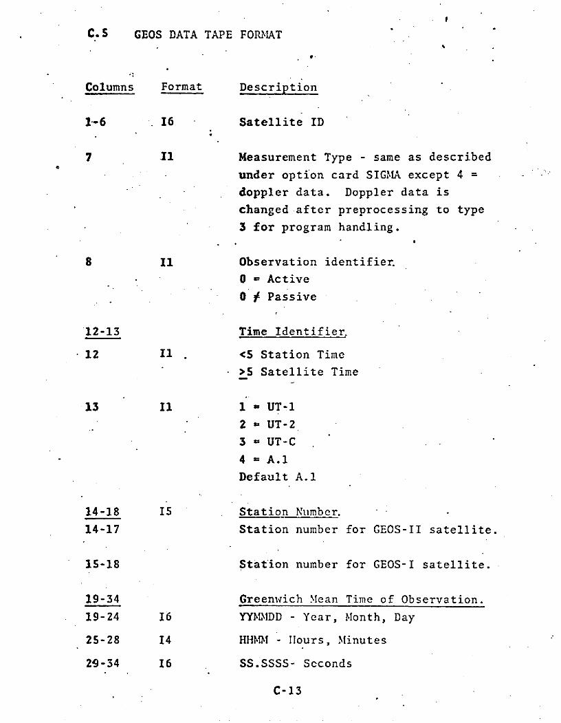
C.5 GEOS DATA TAPE FORIMAT
Columns Format Description
1-6 16 Satellite ID
7 11 Measurement Type - same as described
under option card SIGMA except 4 =
doppler data. Doppler data is
changed after preprocessing to type
3 for program handling.
8 Il Observation identifier.
o = Active
0o Passive
12-13 Time Identifier.
12 II <5 Station Time
>5 Satellite Time
13 Il 1 = UT-1
2 = UT-23 = UT-C
4 = A.1
Default A.1
14-18 15 Station Number.
14-17 Station number for GEOS-II satellite.
15-18 Station number for GEOS-I satellite.
19-34 Greenwich Mean Time of Observation.
19-24 16 YYMMDD - Year, Month, Day
25-28 14 HHNM - Hours, Minutes
29-34 16 SS.SSSS- Seconds
C-13

COLUMNS 35-80 FOR MEASUREMENTTYPES 1, 6, 7, 8, 13 & 14
Columns Format Description
35-53 Observations
35-37 13 Hours (arc) - right ascension,
Degrees - azimuth or X angle.
38-.39 12 Minutes (time) - right ascension,
Minutes (arc) - azimuth
Decimal degrees - X angle.
40-44 15 Seconds (time) - right ascension,
Seconds (arc) - azimuth
45 Al Sign of declination or Y angle.
46-47 12 Degrees - declination, elevation,
or Y angle.
48-49 12 Minutes (arc) - declination or elevation.
Decimal degrees - Y angle.
50-53 14 Seconds (arc) - declination or elevation.
62-63 Equator designation
62 Ii 1 = True; otherwise. Mean.
63 Ii 2 = Equator of reference time.
3 = Equator of date.
All other values; Equator of 1950.
72-74 13 Standard deviation.
Seconds - right ascension or azim .h.
Degrees - X angle.
75-77 13 Standzrd deviation.
Seconds - declination or elevation.
Degrees - Y angle.

COLUMNS 35-80 FOR MEASURI:IENT
TYPES 2, 3, &4.
Columns Format Description
35-53 Observation.
35-50 116- Range in meters; range rate in meters
per second; doppler in cycles per second.
51-53 13 Millimeters of range; millimeters per
second of range rate and .001 cycles per
second of doppler.
64 11 Tropospheric refraction correction
indicator.
=2 or 4 - correction not applied.
=1 or 3 - correction applied.
=9 - correction not applied.
Measurement type - French
Laser Range.
65-67 13 Range standard deviation in meters.
68-70 13 Millimeters or range standard deviation.
71-76 16 Refraction coefficient for French Laser Data.
75-77 13 Standard deviation of range rate in milli-
meters per second or doppler in .001 cycles
per second.
80 Il Transponder channel for GRARR data.
=0 - A channel
=1 - B channel
=2 - C channel
C-15

SCOLUMNS 35-80 FOR
MINITRACK DATA
Columns Format Description
38-53 Observations.
38 Al Sign of Cosine Alpha.
39-45 17 Cosine Alpha (Implied decimal in 39). .
46 Al Sign of Cosine Beta.
47-53 17 Cosine Beta (Implied decimal in 47). m
C-16

A Mod of NGSP (GEOS) Format for VLBI and Average Range Rate
Input to GEODYN
Field Columns Format Description
1. 1-6 16 Satellite ID*
1-2 Year of Launch
64 = 1964
'65.= 1965
-etc.
3-5 Order of Launch
6 Component Identifier
l=a
2 =b
etc.
2. 7-8 12 Type of measurement
81 = time delay VLBI Tg
82 = fringe rate VLBI vF83'= two way average range
rate
84 = three way average Rrange rate
3. 9-11 Blanks
4. 12-13 Time Identifier
12 II 5 = Satellite time
0 = Station received time
*as per COSPAR numbering system
C-17

Field Columns Format Description
13 I 1 = UT1
2 - UT2
3 - UTC
4 = A.1
All other values UTC
5. 14-17 14 Station Number
For measurement type 81 and 82
Reference Station Designated.
For measurement types 83 and 84
Receiving Station Designated.
Network numbering systems are
as follows:
0001 - 0099 USB
0100 - 0499 Not used
0500 - 0599 Deep Space (JPL)
•.0600 - 0999 Not used
1000 - 1999 NASA STADAN
1000 - 1099 Minitrack
1100- 1199 S-Band Radar
1500 - 1599 Minitrack
1600 - 1699 VHF Radar
2000 - 2999. U.S. Navy Doppler
3000 - 3999 U.S. Air Force Optical
4000 - 4999 Interagency C-Band
C-18

Field Columns Format Description
5000 - 5999 U.S. Army Secor
6000 - 6999 Worldwide BC-4 Network
7000 - 7999 NASA SPEOPT
8000 - 8999 International Observers
9000 - 9999 SAO
6. 18 Blank
7. 19-34 GMT of Observation
19-20 12 Year
64 = 1964
65 - 1965
etc.
21-22 12 Month
23-24 12 Day
25-26 12 Hour
27-28 12 Minute
29-30 12 Second
31-34 14 .0001 Seconds
8. 35-36 Observation time correction
35-36 12 Time correction in microseconds to
be added to GMIT.
C-19

S"" arch.1, 1973
Field Columns Format "Description
9. ' 37 11 . Refraction Indicator
S'O Obs. corrected for troposphere
... " . -and ionosphere
. .. Obs. corrccted for ionosphcre
but not troposphere
. *2 Obs. corrected for troposphere
.. . .but not ionosphere
-3 Obs. not corrected for tropo-
sphere or ionosphere
10. 38 11 Transmitter Frequency ndictor
S0 Unified S-Band
=I 1 GRARR S-Band Channel A
= 2 GRARR S-Band Channel 11
S* = 3 GIRARR S-Band Channel C
. 4 GRARR 1BF
11. 39-42 14 Station Numbcr
For measuremeint types 81 and 82
the second-receiving station
SFor measurecment types 83 and S4.
the transmitting station
Same numbering convention as
columns 14-17
12. .43 1. 1 =IE Scale Factor Indicator foro Observations
Measuremecnts should be multiplied
by 1 0 (IE-4) to achieve nominal un
For example:
IE = 4 indicates R observationsare in nominal units.
IE = 7 indicates i observatins
are in K /soc.
IE = 1 indicates T obscrvat.c::s

March 1, 17Fici.d Columns Format Description
13* 44-58 F15.10 Unscaled Obscrvation. (Decimal implied between
columns.48 and 49)
.. .. Nominal Units:
(see colutn 43 description)
• . .-- WKm.
-. ./sec
14. - $9-65 7. 6 Observation Si na
(Decimal implied betiecenS • -... colur.ns 59 and 60)
Units:
- * - Ml./secM/sec
s15. 6 -0 for i only
66 I1 Receiver ".!ount Type
1 XY (East-west)S2 XY (North-Souilth)
3 Azimuth - Elevation.4 fHour angle - Declination
67-69 x3 Antenna Axis D~ 3lA n t c n e- 1S ft f o r
Reccivr ! '. Recic- in -!etes (Decical impl ie* *. betcceen columns 68 and 69)
70-72 F3.1 Antenna Ais nt orTransnj ter in ct s tC4*c*j ctor s 7D aldimplied bCtwec:n columns 71 a- ";n

Field Columns Format Desc in tion
73 I1 Transm itter Mount Typc1 XY (East-West)
= 2 XY (North-South)
.. • 3 Azimuth - Elevation
S.. - -' .. 4 Hour angle - Declination
... 74-80 17 Counting Intcrval for R in
-.Milliseconds
SC
* . "
.C-21.1
• • • ..
• C-2I.

A Mod of NGSP (GEOS) Format for Altimeter and Satellite toSatellite Data Input to GEODYN
Field Columns Format Description
1. 1-6 16 Satellite ID*
1-2 Year of Launch
64 = 1964.65 = 1965-etc.
3-S Order of Launch
6 Component Identifier
1=a2 = betc.
2. 7-8 12 ~ Type of measurement
.92 = Summed Range93 = Summed Range Sat
Rate I -sat94 = Altimeter Height
and Height Rate
3. 9-11 Blanks
4. 12-13 12 Time Identifier
12 5 = Satellite time0 = Station received time6 = Satellite time corrected
for satellite clockerrors
*as per COSPAR numbering system
C-22

Field Columns Format Description
13 1 - UT12 = UT23 = UTC4 = A.1All other values UTC
5. 14-17 14 Station Number
For measurement type 94.station is always -4.
For measurement types 92and 93 Tracking StationDesignated.
Network numbering systemsare as follows:
0001 - 0099 USB0100 - 0499 Not used0500 - 0599 Deep Space (JPL)0600 - 0999 Not used
1000 - 1999 NASA STADAN1000 - 1099 Minitrack1100 - 1199 S-Band Radar1500 - 1599 Minitrack"1600 - 1699 VHF Radar
2000 - 2999 U.S. Navy Doppler3000 - 3999 U.S. Air Force
Optical4000 - 4999 Interagency C-Band5000 - 5999 U.S. Army Secor6000 - 6999 Worldwide BC-4
Network7000 - 7999 NASA SPEOPT8000 - 8999 International
Observers9000 - 9999 SAO
6. 18 Blank
C-23

Field Columns Format Description
7. 19-34 GMT of Observation
19-20 12 Year
64 = 196465 = 1965etc.
21-22 I2 Month
23-24 12 Day
25-26 12 Hour
27-28 12 Minute
29-30 12 Second
-431-34 14 10- 4 Seconds
8. 35 11 Refraction Indicator
0 = Observation not cor-rected for troposphereor ionosphere.
1 = Observation corrected fortroposphere but not forionosphere.
2 = Observation corrected forionosphere but not for
troposphere3 = Observation corrected for
both troposphere andionosphere.
9.. 36-54 Observation of Range, RangeRate, or Heighit.
r- I A

Field Columns Format Description
(9.cont.) 36-51 116 Meters of Range or Height, ormillimeters/second of RangeRate.
52-54 13 Millimeters of Range or Height,or micrometers/sec of Range Rate
55-80 For Range or Range Rate
10. 55-60 16 Sigma for Range in millimeters,or Range Rate in micrometers/second..
11. 61-66 16 Satellite ID for relaysatellite.
12. 67 .11 Transponder Channel
1 - A channel2 - B channel3 - C channel
55-80 For Altimeter
10. 55-56 12 . Meters of Height Sigma.
11. 57 11 10-1 meters of Height Sigma.
12. 58-60 13 Centimeters/second of HeightRate Sigma.
C-25

Field Columns Format Description
13. 61 11 Subsatellite geographyindicator
0 = No information avail-able.
1 water (ocean or sea)2., land (includes lakes)
14. 62-80 Height Rate Observation
62-77 116 Millimeters/second of HeightRate measurement.
78-80 13 Micrometers/second of HeightRate measurement.
C-26

C.6 GEOS-C DATA FORMAT April 8, 1974
INTRODUCTION
The GEOS-C satellite will be tracked by many different
systems and networks of tracking stations. It is intended
that this format will accomodate data taken from all track-
ing systems and networks as well as altimeter data taken
by the satellite. As a consequence of its design character-
istics this format not only meets the specifications of the
GEOS-C project but also the precise orbit determination
requirements of all currently existing satellites.
Since the format is a card image representation, it
is ideally suited for transferring data between the different
types of computer facilities supporting the GEOS-C project
research. The only character images used by the format are:
integer numbers 0-9
letters of the alphabet A-Z
blanks, and
minus signs
All decimal points are implied, therefore eliminating the
need for that character representation.
C-26.1

Descriptions of columns 1-32 for all measurement types.
Columns Subset Description
1-7 Satellite - ID
8-9 Measurement Type
10-14 Right Ascension and Declination
10 = Optical
11 = Laser Optical
15-19 Hour Angle and Declination
15 = DSN S-Band Radar
20-29 Range or Range Difference
20 = Laser
21 = C-Band Radar
22 = C-Band VLBI Range Difference Radars
23 = DSN S-Band Radar
24 = USB Radar --
25 = GRARR S-Band Radar
26 = GRARR ATS-R C-Band Radar
27 = GRARR VHF Radar
30-39 Range Rate or Range Rate Difference
30 = Combined DSN/USB Radars
31 = C-Band Radar
32. = C-Band VLBI Range Rate Difference
Radars
33 = DSN S-Band Radar
34 = USB Radar
35 = GRARR S-Band Radar
36 = GRARR ATS-R C-Band Radar
37 = GRARR VIF Radar
38 = TRANET Doppler
39 = Geoceiver Doppler
40-44 Altimeter Height
45-49 Available for additional measurement
types such as Altimeter Height Rate.
C-26.2

April 8, 1974
Columns Subset Description
50-54 Z and m Direction Cosines
51 = Minitrack Equatorial Mode
52 = Minitrack Polar Mode
55-59 Available for additional angles
or cosines
60-63 X-Y Angles (East-West)
60 = USB Radar
64-69 X-Y Angles (North-South)
64 = USB Radar
65 = GRARR S-Band Radar
66 = GRARR ATS-R C-Band Radar
67 = GRARR VHF Radar
70-79 Azimuth and Elevation Angles
70 = Laser
71 = C-Band Radar
73 = DSN S-Band Radar
80-89 Available for additional Range type
measurements.
90-99 Available for additional Range
Rate type measurements.
10-11 Time System Indicator
10 0 = Ground Received Time
1 = Satellite Transponder/Transmitter Time
2 = Ground Transmitted Time
3 = Satellite Receiver Time
11 0 = UT-0
1 = UT-1
2 = UT-2
3 = UT-C
4 = A.15 = A.3 (A.T. B.I.H.)
6 = A-S (Smithsonian)
C-26.3

April 8, 1974
Columns Subset Description
12-16 Station ID
17-32 GMT of Observation
17-18 yearYY .
19-21 Day of Year
DDD
22-26 Time of Day (Seconds from midnight
GMT)
27-32 Fractional Part of Seconds (in
microseconds)
C-26.4

Columns 33-80 for Right Ascension/Declination and Hour Angle/
Declination Data (Types 10-19)Columns Subset Description
33 Beacon activity indicator
0'= Beacon Active
1 = Beacon Inactive or no Beacon
34-35 Equator and Equinox designation
34 0 = Mean equator and equinox
1 =.True equator and equinox
35 Date of equator and equinox
1 = Standard equator and equinox
(Jan. 0.0, 1950)
2 = Jan. 0.0 of year of observation
3 = Equator and equinox of date
(instant of obseivation)
4 = DODS reference date
(0 hr. Sept. 18, 1957)
36-54 Observation Data
36-38 R.A. or H.A. (hours)
39-40 R.A. or H.A. (minutes of time)41-45 R.A. or H.A. {XX.XXX Seconds of time)46 Sign of declination
47-48 Declination (degrees of arc)49-50 Declination (minutes of arc)
51-54 Declination (XX.XX arc seconds)
55-57 Preprocessing Indicators
55 0 = Data has been corrected for annualaberration effects
I = Data not corrected for annual aberration
S6 0 = Data has been corrected for parallactic
refraction
1 = Data not corrected for parallactic
-refraction
C-26.5

April 8, 1974
Columns Subset Description
57 0 = Data has been corrected for diurnal
aberration
1 = Data not corrected for diurnal
aberration
58-61 Standard deviation in R.A. or H.A.
XX.XX Arc Seconds multiplied by
cosine of the declination
62-65 Standard deviation in declination
XX.XX Arc Seconds
66 ,Preprocessing Report
0 = Report not indicated
1 - 9, A - Z Values to be.assigned.
67-80 Not Used.
C-26.6

April 8, 1974
Columns 33-80 for range and range difference* measurements
(Data Types 20-29)
Columns Subset Description
33-35 Preprocessing Indicators
33 0 = Data has been corrected for ionospheric
refraction effects.
1 = Data not corrected for ionospheric
refraction.
34 0 = Data has been corrected for
tropospheric refraction effects.
1 = Data not corrected for tropospheric
refraction.
2 = Data has been corrected for tropospheric
refraction using the correction formulas
for international laser data (see cols.
76-80).
3 = Data not corrected for tropospheric
refraction. Columns 76-80 contain
coefficient for use with international
laser formulas.
35 0 = Data has been corrected for transponder
delay effects.
1 = Data not corrected for transponder delay.
36-54 Observation Data
36-45 Range or Range Difference (Km)46-54 Range or Range Difference
XXX.XXXXXX Meters
55-56 Preprocessing Indicators
55 Preprocessing Report
0 = Report not indicated
1 - 9, A - Z values to be assigned
*Range Difference - Time Delay VLBI
C-26.7

April 8, 1974
Columns Subset Description
56 Transponder Channel for GRARR
1 = Channel A or 1st sidetone2 = Channel B or 2nd sidetone3 = Channel C or 3rd sidetone
or
Transponder type for other systems
1 - coherent2 - non-coherent
57-61 Reference.station number for range diff-
erencing or transmitting station number
for station-to-satellite-to satellite-
to-station data.
62-68 Relay satellite-ID for satellite-to-
satellite data.
69-73 Measurement standard deviation
XX.XXX Meters
74 Range ambiguity indicator
For DSN S-Band
1 - MARK IA (824809582.0 m)2 - TAU (151285510.38518 m)
For USB
1 - 824809582.0 m
For GRARR S-Band
1 - 18737031.3 m2 - 4684257.8 m3 - 936851.6 m
75 Not used
76-80 Tropospheric. refraction correction
XX.XXX Meters
or,
Coefficient of Tropospheric Refraction
international lasers (see col. 34)
XX.XXX Meters
C-26.8

Columns 33-80 for range rate, doppler, and range rate difference*
measurements (Data types 30-39)
Columns Subset Description
33-35 ' Preprocessing Indicators
33 0 = Data has been corrected for ionospheric
refraction effects.
1 = Data not corrected for ionospheric
refraction.
34 0 = Data has been corrected for troposphericrefraction effects.
1 = Data not corrected for troposphericrefraction.
35 Receiver Mount Type
1 = X-Y (East-West)
2 = X-Y (North-South)
3 = Azimuth-Elevation
4. = Hour angle-declination
36-42 Counting interval for average range rate
data (Types 30,33,34).
XXXXX.XX Seconds
Or,
Tropospheric refraction correction for
other range rate data types.
XXXXX.XX cm/Second
43-54 Observation Data
43-49 Range rate or range rate difference
XXXX.XXX Km/Second
50-55 Range rate or range rate difference
XXX.XXX Millimeters/Second
*Range Rate Difference - Fringe Rate VLBI
C-26.9

April o, 1JI4
Columns Subset Description
56 Preprocessing Report
0 = Report not indicated
1 - 9, A - Z Values to be assigned.
57-61 Reference station number for range
differencing, or transmitting station
number for station-to-satellite-to-
satellite-to-station data or average
range rate data.
62-68 Relay satellite -ID for satellite-to-
satellite data.
69-73 Measurement Standard deviation
XXX.XX milli-meters/second
74 Transmitter or reference station Mount
type
1 = X-Y (East-West)
2 = X-Y (North-South)
3 = Azimuth-Elevation
4 = Hour angle-declination
75-77 Receiver antenna axis displacement
XX.X Meters
78-80 Transmitter or reference station
Antenna axis displacement
XX.X Meters
C-26.10

Columns 33-80 for Altimeter Data (Types 40-44)
Columns Subset Description
33-41 Altimeter Height Measurement (0)
X,XXX,XXX.XX Meters
42-44 Sigma Measurement
X.XX Meters
45-47 Tropospheric Refraction
= 0 - none applied
S0 - value applied
X.XX Meters
48-49 Ionospheric Refraction
= 0 -.none applied
1 0 - value applied
.XX Meters
50-54 Geoid Height
50 Sign of Height
51-54 Value of Height
XX. XX Meters
55-58 Tide Height
55 Sign of Tide
56-58 Value of Tide
X.XX Meters
C-26.11

April o, .'V/4
Columns Subset Description
59-65 Satellite Latitude*
59 Sign of Latitude
60-65 Value of Latitude
XX? XXXX
66-72 Satellite East Longitude
XXX? XXXX
73-77 Sea Surface Height (0-h)
Altimeter Height Measurement
less Satellite Height (h)
above Spheroid*
73 Sign of Height
74-77 Value of Height
XX.XX Meters
78-79 Blank
80 Preprocessing Report
0 = Report not indicated
1-9, A-Z = Values to be assigned
C-26.12

Columns 33-80 for Minitrack Data (Types 50-54)
Columns Subset Description
33-34 Refraction Indicators
33 0 = Data has been corrected for
ionospheric effects
1 = Data not corrected for ionosphere
34 "0 = Data has been corrected for
tropospheric effects
1 = Data not corrected for troposphere
35 Not Used.
36-54 Observation Data
36 Not Used.
37-45 Cosine t
XXXX.XXXXX Mils
46-54 Cosine m
XXXX.XXXXX Mils
55-57 Not Used.
58-61 Standard Deviation in Cosine Z
XX.XX Mils
62-65 Standard deviation in Cosine m
XX.XX Mils
66 Preproqcessing Report
0 = Report not indicated.1 - 9, A - Z Values to be assigned.
C-26.13

April 8, 1974
Columns 33-80 for X-Y angles and Azimuth and Elevation angles
(Types 60- 79)
Columns Subset Description
33-34 Refraction Indicators
33 0 = Data has been corrected for
ion.spheric effects.
1 = Data not corrected for ionosphere
34 0 = Data has been corrected for
tropospheric effects.
1 = Data not corrected for troposphere
35 Not Used.
36-54 Observation Data
36-38 Azimuth or X angle (degrees). Sign of
X angle appears in column 36.
39-40 Azimuth or X angle (arc minutes)
41-45 Azimuth or X angle
XX.XXX Arc Seconds
46 Sign of Y angle
47-48 Elevation or Y angle (degrees)
49-50 Elevation or Y angle (minutes)
51-54 Elevation or Y angle
XX.XX Arc Seconds
55-57 Not Used.
58-61 Standard deviation in X angle or azimuth
XX.XX Arc Minutes
62-65 Standard deviation in elevation or Y angle
XX.XX Arc Minutes
C-26.14

April 8, 19/4
Columns Subset Description
66 Preprocessing Report
0 = Report not indicated
1 - 9, A - Z Values to be assigned.
67-71 Tropospheric refraction correction to X
angle
XXX.XX Arc Minutes
72-76 Tropospheric refraction correction to
Y angle or elevation
XXX.XX Arc Minutes
77-80 Not used.
C-26.15

C.7 RAP DATA FORMAT
(To Be Determined)
C-26.16

C.8 GROUNDTRACK TAPE FORMAT
The Groundtrack tape is written by GEODYN specifi-
cally for input the GROUNDTRACK graphics program. The
Groundtrack tape format is as follows:
Columns Format Description
1-6 16 Date in YYMMDD.
9-12 14 Hours and minutes in HHMM.
15-21 F7.4 Seconds in SS.SSSS.
24-29 A6 Station name
32-46 F15.8 Satellite Geodetic. Latitude
in degrees.
.-. 49-63 F15.8 Satellite .East Longitude in
degrees.
66-80 F15.5 Satellite height in meters.
Total = 80 bytes.
C-27

C.9 ORB1 TAPE FORMAT
An ORB1 tape is a binary satellite ephemeris tape
having a logical record of 350 double precision words.
There are three types of records on the tape - a title
record, data records, and a sentinel record.
C-28
T-

ORBITAL TAPE FORMAT-1 (TEB)
WORDNUMBER BINARY TITLE RECORD FORMAT
1 Form of:data identification = 76796291
2 Satellite number
3
4. Date U.T.
5' Day count of year Start time of satellite
6 Seconds of Day Data
7 Date U.T.
8 Day count of year End time of satellite
9 Seconds of day Data
10 At, interval between satellite data items in seconds
27 Date Coordinate system
28 Day count of year Reference data time and position
29 Apparent sidereal time in radians
Spares
80 Cd, atmospheric drag parameter
81 Area of satellite in cm.2
82 Mass of satellite in grams
91 Lunar perturbations indicator
(= 1 indicates lunar pert. were used in determining orbit
= 0 indicates solar pert. were not used)
92 Solar perturbations indicator
(= 1 indicates solar pert. were used in determining orbit
= 0 indicates solar pert. were not used)
101 to, epoch time (C.U.T;)
102 a, semi-major axis at to (C.U.L.)
103 e, eccentricity at to
104 v, true anomaly at to (radians)
105 x satellite position
106 y vector r at to (C.U.L.J
107. z
C-29

ORBITAL TAPE FORMAT-1 (TEB) (Cont.).
WORDNUMBER BINARY TITLE RECORD FORMAT
108 x : Satellite velocity
109 y Vector r at to (C.U.L./C.U.T.)
110 z
111 r, magnitude of r at to (C.U.L.)
112 r, magnitude of r at to (C.U.L./C.U.T.)
114 M, mean anomaly at to (radians
.116 w, argument of perigee at to (radians)
117 i, inclination at to (radians)
118 0, right ascension of ascending node at to (radians)
120 n, mean motion at to (radians/C.U.T.)
121 E, eccentric anomaly at to (radians)
122 ;, rate of change of argument of perigee at to
(radians/C.U.T.)
123 6, rate of change of R.A. of
ascending node at to (radians/C.U.T.)
124 P, period at to (C.U.T.)
125 Height of perigee at to (C.U.L.)-
126 Height of apogee at to (C.U.L.)
191 Year (last 2 digits)
192 Month
193 Day Date and
.194 Hour Time of Epoch
195 Minute
196 Seconds x 1000
200 Indicator of theory used to compute orbit
(= 1 indicates PE orbit generator
= 2 indicates Gill Integration orbit generator
= 3 indicates Brouwer orbit generator)
C-30

DATA RECORD
WORDNUMBER DESCRIPTION
1 Date (YYMMIDD) Time of first
2 Day C6unt of Year (DDD) satellite position
3 Seconds of Day (SSSSS) velocity vector = t
4 At, interval between position-velocity vectors
.5S Spare
6 x Satellite position vector
7 y in km.
8 z
9 x Satellite velocity vector in
10 y km/sec.11
12-305 49 other satellite position velocity vectors
at times t+At, T+2At, t+3At,... t+49At
306-350 Spares
Notes: If the last data record contains less than 50
position-velocity vectors, the remainder of the
record is filled with nines (99999999.DO)
SENTINEL RECORD
The first word of the sentinel record contains
nines (99999999.0DO). Words 2-350 are spares.
C-31

C.10 PCE DATA TAPE FORMAT
A PCE data tape may be written by GEODYN in orbit
generator mode or read by GEODYN in data reduction mode.
The format is as follows:
Columns Format Description
2-3 12 Measurement type
16 - X
17 - Y Inertial18 - Z Geocentric19 - Cartesian
Coordinates20 - Y
21 - Z
22 - a.
23 - e
24 - i OsculatingGeocentric
25 - Keplerian26 - Elements
27 - M
4-9 16. Date of data (YYMMDD)
10-13 14 Hours and minutes.
14-21 F8.4 Seconds
22-45 D24.16 Measurement
46-55 D10.4 Measurement standard deviation
Units for measurements and sigmas are:
X,Y,Z,a - meters (a - m)
X,Y,Z - meters/second ( - cm/sec)
e - dimensionless (a - ppm)
i,1,w,M - degrees (u - arc sec)
C-32

C.11 RV TAPE FORMAT
An RV tape is a satellite ephemeris tape which
is output by GEODYN specifically for use by the DELTA
analysis and graphics program. An RV tape is a binary
tape written without format control. The RV tape word
format is as follows:
.Word Type Description
1 DP Days from Jan 0.0 of the reference
year for the arc.
2 I Date in YYMMDD.
UTC
3 I Hours and minutes in HHMM. Time
System.
4 R Seconds.
5-10 DP Satellite inertial position-velocity
vector in meters and meters/second.
11 DP Satellite latitude in degrees.
12 DF Satellite longitude in degrees.
13 DP Satellite height in meters.
Total = 92 bytes.
The last record has a value of 999.0D0 in the
first word.
C-33

C.12 GEODYN SCRATCH FILES
GEODYN uses seven scratch files. Some of these
files are direct access (D.A.), but most are sequential
(Seq.). The uses of these files are described below:
File Type Description
10 Seq. Used in the processing of doppler data in
GEOS format.
11 Seq. Used in the processing of all GEOS format
data.
12 D.A. Used for storage of all data in data
reduction mode.
13 Seq. Used for the storage of solar and geo-
magnetic flux data.
14 Seq. Used for the storage of a priori information.
15 D.A. Used for the storage of updated parameter
values.
16 Seq. Used for storage of that segment of the
normal matrix pertaining to individual arcs.
C-34

March 1, 19-1.
C.13 GEODYN .SIMULATED DATA TAPE
GEODYN has the capability of writing an output tape
with the calculated observations in place of real observa-
tions. The tape is a binary unformatted tape designed for
the purpose of testing the GEODYN estimate process. The
following format is a nominal format which corresponds to
internal variable names only. This format should not be
interpreted rigidly for all measurement types.
Word Type Description
1 I Date in YYMMDD.
2 I Time in HHMM.
3 D.P. Seconds.
4 D.P. First calculated measurement.
5 D.P. Second calcualted measurement.
6 D.P. Standard deviation of first measurement.
7 D.P. Standard deviation of second measurement.
8 I Station number.
.9 1*2 Measurement type.
10 1"*2 Number of measurements (1 or 2).
11 I Satellite ID.
12 D.P. Tropospheric refraction -index.
13-14 D.P. Transit times for average range rate data.
15 1"*2 Transponder channel.
The measurements and standard deviations are in
"natural" units.
length - meters
time - seconds
angles - radians
The measurement types are the same as those for the
SIGMA card.
C-35

C.14 SC4020 PLOT TAPE FORMAT
The SC4020 Plotter Driver Tape contains a contiguous
stream of 36 bit SC4020 commands. This stream of commands
is blocked 682 words of length 36 bits each to efficiently
utilize the F-53-1A off-line buffer. The particular command-
by-command format of any given Driver Tape is solely a
function of the particular information being plotted.
C-36

-APPENDIX D
BUILT-IN STATION P3SITIONS
STAI, ! G--CTIC LATITUSE ' EAST LJGITU- SpnEnIO ,4 fEIGMr
uA . -1 PC SEN SEC ONDS DEG - SECLNOS (mETERS)
MILJ 1 26 30 29.st514 279 13 23.2243 -45000
GB683 2 i 37 57*6002 2E1 45 44*0263 -&6.000
SCA3 3 42 21 4 232S 2S5 20 3Ce5710 - b6000
AN'. 3 4 1 ; 0 5.e6273 258 1 5055 24 -27e000
CYI3 27 -5 51.7824 344 21 52.~-12 20e*000
ACN3 o -7 - 57 -19*3126 3-5 40 209220 555.000
MAD=O 7 .40 27 19,726e 355 4? 53.0274 321.030
:.; j -24 -!- -23*93CO 113 %3 31.2153 1*030
wA 3 1 13 37o6e5e 144 14 I 9202 76*3000
SKJ 1; -3t -35 -0.24%5 143 5-1 35.110 11*50003
MAW3 11 .2 7 34e05!7 2CO 20 5.*933 1123*CJ
GDSS 1Z A5 20 29.4543 243 7 34.3297 920.000
GY43 13 27 57 46.7313 2g9 15 43.5135 -28000
TEXK 1. e7 39 12.7713 2t2 37 1, % 13 -41.o00
TC 3 13 3E 5 5a e4452 2E3 9 25 e469 - *000
2100 i11 35 .23 22 *1l39 2t3 9 1o553 9q3.000
ECD .;i 35 17 59* E-3 243 11 3q*7211 ;36.000
VE-S LAJ 3o 14 51.*255 243 12 173 01 100*000
"4A) 4 3! 25 33. 155 243 6 37. 140 974o*00
C-M3 -wl 1 -22 -55e2'C 126 53 14.2774 14o030
7T03 -jb -7- -3.2*a3 . Ie a s 52.39510 673.003
jo-3 .: - . -51 -2.7=01 27 AI a3213 1410.033
R3D 4l C 25 43.5-5~ 355 '3 3.0* 5 525.300
CE, 1 40 27 113125 355 37 55.3a75 775*030
"aT) 71 2 28 45.se71 279 26 1.0750 -41*000
KOUR'JJ 1 ,0 15 3. 221 3C7 11 41*04-t7 -18*030
3PC1 NT Iv ,t 33 25 49.8C 3 2E2 54 4a.1'33 -- 3.93
IPT4Y.-, 1J.) 2; 32 53.1513 279 3 4.2737 -42..00
L0.IT3 13; 0 -7 -22.3452 211 25 15t 13 35 I o13
L LI,' 4 1 G -11 - -37,0634 252 5Z 91431 50.733
SNTAs. 10,, -33 -3 -5 ; .07- 26e 1: 53 .7
:0 2 713.9;0
NEw-L3 1312 47 29.2567 3C7 to 46,2670 480:0
COLeGC 1013 ' 52 17*,814 212 9 36.3525 153*3i7
GFO'J 1 .1J .d 1 21,54* ; 22 59 19 '6100 203.1 2
WNKFL S 113 21 * -6.4180 359 1 1 3.0926 9C 410
JO JUR 1LJ1 -2o -53 -1. SO e 27 42 26.21J3 15,0.9
vCJ V 1317 J3= 1 * .09 243 5 59o0173 976*254
CCr~i- - 101 -i1 -2.3 -25*P.16 1-6 52 1541;53 130*403
ULAi a' l -4 3.* 775 212 25 JCoC077 213.125
1 ' .. :1 Jo 25 ae oP3e 2E2 4 44*7303 .
IFT'Y,.e I..i . 32 -53.1513 27E 1 4*2737 -42*000
MACA5 1 -1S 0 -325915 47 17 5 3066 1339.777
ICC'.1 < 2 -1i -23 *-'-5d1c 13c 52 15 e 1ib 3 130.033
IC'JIT C -37 -2:o 3"42 2E1 25 15.i-37 5355*13
1LI'o ' -I -- o -'? .1
"4 212 -0 5*,I.31 33*7C3
1SAT40 rj,: -331 .4 .42,,7< 2v9 19 ez*7b02 713o9i3
%..JAV 3 1;b " *14 243 5 53 '1 70 37 2 4
1JJ 'J- - 3 -1) * 27 ;2 2C.21,3 1540 *77
REPRODUCIBILITY OF THE
ORIGINAL PAGE IS POOR
D-1

.vj d Gc4aC5TIC LATITUDE EAST LON17TU2)-- SpHEq0ID HZ1H
sAl4 KN=4k. ;3kc MN *SECC1NDS 3EG 44 SEC)NOS (MZTER31
IN=-4tL 10.32 '.7 4,4 2go2e57? 3C7 16 46o2670 46e0'30
ICOLEG W ' e4. S-2 17.* 1'A 212 -2 36.3525 156*367
IGFOZmC 13.3b 4, 1 21.9 *2E&;5 z2 5 1963 20301 2
1-N,(FL 13 - i .31 26 469 41 b0 3!9 13 3.0326 904110
*IULASK I G_-o c~ r* 350'775 212 2-3 30.6377 233*125
1P3OIN -10-7 .3k- 12 702943 277 .7 41.2732 549*133
1OQ VIL 1J.0a - 3 Z-37 -. 32. 66; 14'3 57 14.9123 949*578
1.Oas, !J'.a .3: 12 7*30S7 277 7 40.4741 15O0363
'TAJA"4 13)4. - L i 0 -32* 3; ' 47 17 59*30O& 1-907
.MAD34-IS I 1. -LS -1 -14,47ni 4? 13 11*335o t332.030
q0* AO~N i 11c C.: 1 Z 1 45s65iC 277 7 25o-147 P-134130
SNT A r;S 11.;7 -3 ji -402T5A 2 ss 20 0*6344 7270110
44ACARV 1=22 -1 1 -1 - 17 02!"74- 47 13 1194102 1391s000
CCSRANV I. 4: J 11 41 *4! e-4 2177 26 e 132 .814003J
SNT ASAV 1;;_ -j -4 -i -'t773'-' 269 23 0e5252 727.031
ALA3PV WZ c4 5 i 176 31F51 212 24 .17s13a2 34 000.2
ANTZ.:;A zajo 17. S -35*16 2 f 2 I~ 12 39*6937 -54*.371
GFNVr -432 3 J2 23 ^.9a .47%4 2fs _372 lq .2E61 i90
GRV!LL -. 3. 44 25 32.4ES' 2~ dla 3 09AF -16.654
9! SO 3'31 42 27 17 o21ed 2s. -43 3se4isi 30*054
SEAME 3 2VO2 J3 0:6 b0.0C':Z3 271 44 51.1217 17.430
SbNA'4 13 17 Z4 1201053 27f 1 29. 8713 7.4-Ad
Gr%:,T;ZK :4u Id I 9,~8. ". 1 t 2 it 51 150157-) -.510052
czAo .Z= 1: 5 25* 02435 zG 40741-3 -40q731
TF.04L2Z 407 10 -4 35e 74d I? 2Se 23 23.1i75 243051i
47A4P -1 :!b 0 71. 0 Zf2 3? g.2202 243.171
Tvit 4- 32 3c 7 259';49 f 2 47 2 *a5 36 255o67:3
rCTmrG4 3 6 1 24 576 !;143~ ; '0 Co=43 364.65.3
ATI-AGR 3.Qc i 3 J7";3 2tel1u27 23 44 2 a :5 53 453*7VI
TC2 : i-c* -.0 2, ; 4.t6 35A 34 35 a3-71-* 63300;4
1(1N-LY 71 34 22 Sqv'3471 2 1 5 1; 1.,3333 -13.332
p~., - .. ~ i i 0 F. 05 12 F ?7e i.). 40% s :0 %
J;-aAF27 1 lseeol! 2' 1 ,3 I -a0767
cE. -'A Ns 7 1. Z' 1,;.100 3 2E-3 3C 5 % -3 2 _)2 -4735
- C S T .z1 d 0 2 5 - l 2 7p J3 4ZO163 90S
I.:'-viv Y V4 4 7 5 4.1364 2 !5 7 5%3 93 7* 1340*1)9
-. T4~: - ., -4- 7~ AI.:~k 27 21J 24%071
*Wi .. 1 17 A 37.C; 6~ 1 2,301304 3j)
D-2 REPRODUCIIITy OF THED- 2ORIGINAL PAGE IS PooR,

SAJN G--Cc-:Y1C LAT1tru( CAST L0N.31TUX- Sp'4sRaI2 WEG
tA*4Z- KUPas-N .Jce MN SECONDS DEG mv' SECJNDS (M-ETERS1
!!TPGRT "3al 21 2? 45.3676 21!e 52 4e3242 -27*036
ETQS.VIT 40 Qa 25 21s 3*711 279 20 7.6670 -272
VTU ui 2t 3S 1O. 17t)2 24!t& 55.5-37 7Th *
.0I2 142 ~ 5 337S 2!3 '.54 2.3093 1217.4151
USCIIJ *.1'3 42 21 2'4*00*:4 2 !- 37 48*1?22 11S5*614
WSM123 41..4 32 15% 5.3715 2S3 5* 2v 4 91 1217ot~l
wrS5127 -14:i 33 4.9 50.0332 23 11 0i 27.0505 14S4.313
WSP124. ~33 26 4297072 211 i2 301261l770
CSTl? t i~ ... 5 4eo6. 5 4-:-3 i0 2t*51374 1223*941
ATWPP.'. .. r 3 ? 2; 51. 3351 237 30 -- *2 129 3.276
*A T q2 -i a-1 34 34 55.7822 2 2 26 19.7112 57021
&TRTQI e. J4 34 57*7335 !9 1eo3632 e,4237
UT~pplj Ceta 37 29 510-2S16 227 30 0.7531 - j.o032
%TRVAN 4eto j4 39 S6*S112 2 25 6.*5 131 600:106
EGiL 1,4 rU Z 17 S1 213 161 t&7014 -- !t o147
EGL I NF sj 4 1 25 174-1501 73 12 '0.0 5:5 a671
* PWASN5 44 0 44 14 4s.o z&, 240 21 SO. 1421 220.47-1
.J!i1 ti. A4 i 46.*535 .240 2:* 49.53J4 221.253
I -2 2D 2;0;0 2C0 1is 19.5525) 447*4ti
0!VQ%1p2 - . 3*74P3 ? cl 14 19 a !! 9 493
J4U.FI .. 3 3. 7 17 m,0 0 240 6 B.) 2 .'2C3 -47*353
P%'r-lz I.~ i A 7 17*50:34 240 5 u t994512 4ot5
0MRfSN2 *.d- Z3I 14 S 1 240 125 47*3031 215*.*71
P*4.iSN.; -64' 33 1& 34a.0967 240 23 4205141 219.433
p06rp*-P!3 .Q 34 7 2-3 - , 1 240 53 45.i:553 -47*337
1.11 W4 4 ~ J4 7 2?2o273 t 240 - 0 42*4773 -47.3C
PM4:JK I "-c 1 17*3333 . 2C0 13 16% A14.% -15030?
SCi~ ... - 0# 3 5-3 tl0.201 212 4 .e5A11
ML.LAr k 10 I; 1i 30*7608 2 44 54 46*5563 2737*.7
NSELYt.V .- 1 IF 3160G13 24454 .414 277f;*32n
* ~ I it 2A - 7 -"2 47 t2 2.O00C :? 4 32 57e3016 -&c)
*Natw2= -I? 4 3? 52 2e:)102 2 t4 32 57a7727 -64 *06 0
N140 E. .1:14 47 20 Age 14'- 2 I4 - 4R.ZSI17 -60.474
4io I el d;Z 37 ZO ft954C 25!Al 5 zez1 -04'
N 1 ~3 -- d. 37t; -s 20 52.Si5b152 2 15 2'.) 46 .7 31 l -369795
CSTN~ -'1 - 0 -C5.47ep l7 i 1 0 0 c 132C6207
hTPK AJ ..7 2 e. 7 230.;5z,1 zCj 20 Zp*i112 .
N~J i 20 i2e 1 C ; 5 z3 4tZ4 -3 i a 2
sc %14V -7,--l ~-7.~2 113 4-3 1.'~ 1 loZ.t~ jo;
Id 7 t 70. 0 3!5 25i 5-0- 1 32.57'
*A. 76 Z 35 ? 2 5.7 17 132.633
i! is.B 10 3 41o173
a RiEPRODUCIB3ILITY OF THE,ORIGINALJ PAGE IS POOR
D.3.

STAYL1 01. C~jC_-1TC LATtTUDC e4sr 6ONGITUDC $PtIcxOIO ~G4
14A 4z , hZv-QC MN SEC CN'JS Eil 4'4 SEC')NLIS (METERS)
~E4DI~Jc E9 37.i512 2E2 %o 17%2:55 2 63*j32
C IC AL 0O 42 -,ZC 13.2221 2 4t2 352 7.5624 76.65O
LAISCK ;,43 1 .7 It So 13;8 240 1 45.3724 2*:O
40r.TCN z: v~ *3: 33 B37.0-12 ZdC 23 t1be3544460u
.H.V :43~25 22e i44 2f9 5 904105 2:10274
MAU1,"A 411 4 49 25*1.132 2 C3 32 2o 171 2.7
CAI r. Si 5 3396652 2E4 2 22*71*7 -&*.23 3
F.Tv 4,4T Z040 I1 a5 19e.)474 27% 25 C*431c, -29.3
*iNTAF~ -3 .Q" i~ 0 40674e 273 33J 43,J370 -43*25S
M4C P *FL t- ; z 215 22*4?2E 27 ; I 3;e6'!37 -43 071-:
43ELTVL .02 .p 1 39 a15 3!! ZE3 13 27eS550 -15*254
* CLC0 ul 13 20*024R :9 53 25.0171 150*COO
P ;AN .I6, . 14 0.0175 4A 30 00-'159 760.003
;1ILVAA d ,e 27 11.,41FO4 J 0 3-. 740023 184030O
4PAi%3 .v i 7 45 1 12.017; --- a % 42*01:53 400000
'ACVZ .ti t Jz _ 4!9 0.0226 E2 :51 0.3351 150.030
:5Z4 u~ 4 39. 5.0228 29 45 10*0155 1140000
Tp4 j:) Z AN % -c 20 0.0240 26 AO 0 3102* 75 00 3
TA;'MK 1 :3 ti 41 21 ca,0171; E9 11 12.0231 4*5
AST 14) ;1u3j _j 1 39.9229; 2E3 10 2 50- , 124 '5l-
*LYN-4LK : 'Cfi =: .51 3.1437 23 E-, 'i5 .S104323 4I
T 1. T 1 clii 4, 33 "*~2412 271 37 44.?7c 23.4i
1UN!:A'(7.- <: I 2 *A 2f2 :5 19.0160 203.142
* COLIA 7047 34 T3 315025 A 2e7 47 AOS.)7q- 2129 t5t3
MtEL" 7U~z _;v !2 21 -SoS -:!2 2S5 2) 25 95 31'7 -27oCul'
1pUQ'U ?G.~) Ic is 2Eotb57c 21S4 3 ZJ.,75 14.936
7 1G.Jji 1 12*3t7c 2S.3 13 206i 47 -9
ic: 3, 1 1501~ ?E3 10 2; 0 013
* IC'KVL-' IU'-* J~ z 2 12*70c,0 204 i1 16..4d1,. 124.720
I C,= -V4 0 3~ -if 49a.160C 255 23 33*5733 17t.4 31
131-1424 7071 Z7 1 13*'71LI 279 53 tlZ.664 7*37'
IJU-443 7 v 72 27 1 1&.6 2 7S :5 3 12a.3402 -37*'-2
%j~1773 2:'7 1 14olOSC 2T 79z_3 13*' 774 33*1-
1,oC l7-, _-7 I I&* 3:! r 279 53 13*11a6 -7-1
1SuC! 7 7~ 5 21 e ! 37 279 3 l10.SZ77 221000:
lC~'J7.77 53 5.3eZ 9 ts 37.91_-3.'
1CA' V.4 I'H 2'- -2'.41C2 1 0' %3 1z5 341-12~.
'3,5LAS 7,j.; . 2 L4.09t 2 L 3 13 1.e*
zzA 3. ~ 1 ac%97 '2? 277 7 269i;73 i
~~~~ t:!1 %"22K 1, -5023,3
Z~~L~I7.,~ ~ -. I 11~.~ 11 4i --5 '7 i-.)
"CLi 7-- *1 h1 .'7CL - 7 160474i7 1Y'.S
.a~"*.3 7.. 1 -1 7J7.; 26: -1 1%0o_76~ ~ i.
'AC*-4 JLjA?
RIEPRODUC1BILJ~y OF~
D-4 ORIGINAL PAGES IS po~

STATIPh i.;C.ZTIC LATITUOF FAST L3NG1TUI= SpNRq3to H-Z(JN7
kA4LJIG %*. ZSCONDS IE "M SECON:)S (04ETERS)
SENLAS 13-c 4 4,6 to £87S 0 2 63 10 17.5140 177.606
SFLLAS 7zU- 3t 2? 45.4155 3 13 47 36.30451 38.303
UPGLAS 7.31 32 25 24a 1351 2!3 26 4-396631 1600.-;3;f~.LLA.S 702 - --- 7 -36.,a70C 25 14 E2. S: 26 15704CJ)&A'-LAS' v.;7 - Ie' -27 57 a 4;6 2te 30 24oto7z4 2490003
* EDA ,1 21 41 2.1675 2. 7 &So&!!33 233g.141
HATLAS 7m,29 - -55 -4Co182C- 324 50 7*91-33 25.390
.*Q=LAS I3 2 133 0 4 42*3201; ;3 55 Ste1132 490*323
aA.%SCa .)G. : 34 35e.3336 10 30 1752 2 1 41.*533*OELTl- :=w. :, 0 5974!05 4 22 1502421 46*
I I 49L) 3 ;j13 52 37.19'!o 7 2? 53.34;i 93'1.22-3VALVWS .4 ,11 Z2 S 35o4 35 2 3f8 1 5390- i45 137e-320
~coyag! .J I1 ~ 4 2.9145 3!5 Zi 14. 21 i* 309*627ATM~N z.%S -j14 3~? 19 17.532.2 23 4.3 st4.Cos 1330:3 ;NAUJT:'P -J I1 44 !5 57o5722 S 112 44*7347 694.320
NZCSF 4 ju1 IV 43 33 067e 7 t? 58 6 35-7 405.220
M I'L AJ :Oet, *7 a F5' "2S% 4 i 0 6 t *6 lo 0-71SALA ~ -J 43 -400-)1?2 13! 334 49*5 62
14LU34 t zj eZj t 22.6-;oe 2 1.3 45 .;419 190.010
! moo. - Z.44 1.9145 3!6 Ab 144215-, 30Q-m627
1'WN tCH1 4 7 4 5 a319cI 11 .1 2106075 961o'705
F&ANK :j C" 13 11. .-) 31 3 43 46 3660 143681 )SAWcL~ I~ ?zC C 27 * 7-5 5 3513 47 3545 553*375
HAUTL*2 7i1z =5 -5o 7458 % *2 429597U 636*032
11sJ4 S 3V J~i 25 240.042 2!3 26 e, Is 4 -1 b560O3
1 .LVAA ajt), --; -57 -35.eS7C0 29 14 52o3Th26 1570VC03mu"4'i- .JC3 -ij -b -3.* 0 ' 16 1 25 47 2. 3722 156. 11.6
1 S-1A1 14U v3j c :7 -47.*0058 .3!3 47 2!jo4i35 355.4'v
I T01(Y) IJ jj k;,O; 22*6344 121, 32 1 r .2 40 a 30 0 00~,
I NAT AL IV td 42 VZ1 33a.3227 d9 7 27o302 13560000
10UZPA X. ? G -1c -27 -:57o29-54 Z F 30 24 * 7ol, 24.900.C03IS1. -a,,; 3' 13a.3103 !2 31 11.2723153390
ICUIAC ;j 4 12 .5 25*og~e 2SI 3 .s.6234 203
1JUPT-4 .VI4. 'di 13o;203 271 ii 13o5-04 -30)
1LMAUI) I 31 JI e0 42 25ozF512 2C3 *- A 34.2073 3C31* a I
.044],~0 14 C.4 31.253 3&2 30 25o :0'35 t710033
*MGPK IN~ 4-1.A 31 X.1 2ez 249 7 IE o'v It33 2239*03)
*CU jI~ .. e 3 c tg;2-7 121 1 1. Z.2 877.000
:c~v ,:I -,. -53 - 1,5 3 2;2 23 15, 3455 2406
A .11 --- : -'P -~ 17 32& 53 eats-I -44.a0*3
.? u 17*7215 27?. i-i 120:; -12- -396 73
LVt. ~ Ct2 J'o 'C3C 7 27 333,i93C1
REPRO ~I'x UCIfBiLITy OF THlEOR5IGINAL PAGE IS POOR

$TTZ.%A'C.TIC LATITU'3C EAST LUN4*1TUIE SPHERO2ID PIG4'
PAA4 Nt!1'u~ 6#EC %IN S-%CJ3S DE 4N SECJPN0S ME~TERS)
UZHGOI -2077 46 is loaqi; 2 17 S4.3870 20490,10G4~~ ~ 44 .10 A 23 5:5 £-.3*&6 *-4)e320
CAL!1A<. vp3 j~ .4S7 SO 0 aE-81 2,02 5 7.35 743.444iClk ~Lq 4 t4 33*6732 204 37 22ai223-3 ei..oo
DSL IN I.115 OC 12 39 a')2 0! 10 43 2*6473 595*040rC4S ilJ Ig I 4A 3e'.47?0 150 24 i. 8.299-00
'ITJJH!4 1i; -.- 59 -20o1151 170 2-3 901710 10110033*5ANVT-) I e-. C i5 19052ap_ 17 50 52*3.47'% 144@OCOice~pt -b 2 ~ L f 50o -. 7! 202 5 7 o 1 I' 72;9174POTZA't i., z 22 'S2*;:;; 13 -3 Sbo P5?7 122*054
* 'ELSKK i 3.5 Q 42334F 24 57 5*4209 0 0 U0 a
CAK(Q i4~1. . 32*4213 342 .10 25.3006 7*75A.4VI T 1 L 4' 3b I co C22 17 30 52*4-54 144i.U10
1~ROD 0jUCJIBLITY O- ORIGW1AL PAGE IS Op TH
D-6

August 11, .1973
INDEX
Pa
Altimeter Data C-22,23,24,25,26
Arc Description Cards 1.2-1,2
Arc Set 1.0-1;1.2-1;Section 1.2
Area of Satellite 1.2-46,47
Atmospheric Density 1.1-1
Average Range Rate Input C-17-26
Biases
.Electronic 1.1-11;1.2-26,27
Measurement Biases 1.2-12,13,14
Standard Deviation 1.2-13
Station Timing Biases 1.2-12,13,14
Binary Residual Tape 1.2-36;2.0-8;C-6
B-Matrix 1.1-5;1.1-5.1
B-Matrix Tape 1.2-15,16;2.0-9;C-2,3,4,5
Built-in Stations Appendik D
Central Body 1.1-5.4
Common Set 1.0-1;1.l-l1;Section 1.1
Constant Timing Corrections 1.2-38,39
Constrained Stations 1.1-7;1.1-25
Convergence Criterion 1.1-11;1.1-37
Coordinate Systems. 1.2-4;1.2-8;1.2-IC;1.2-37
Core Requirements 2.0-2,3
Correlation Coefficients 1.1-6,7
DATA Card See Termination Cards
Data Reduction i,ii;1.2-34;1.2-36,37;1.2-53,54;1.2-65,66;2.0-.7;3.0-2,3;4.0-6,7,8;4.0-9,10,11;4.0-12,13;4.0-14,15,16
IEPRO1 ) UCI3ILI pTrI-i O'GQNiVAL PAaE isj O-1 POOR

AUgust JI., 1I
INDEX (Cont.)
Page
Data Tape Output Appendix
Deletion of Data Types
DODS Format 1.2-67
GEOS Format 1.2-70
Denormalization Equation 1.1-17,18;1.2-42,43
Diagnostic Error Messages See Error Messages
DODS Data Base 1.2-6;2.0-6;5.0-1,2,3;Appendix A
DODS Data 1.2-5;1.2-50,52;1.2-66;1.2-67;2.0-8;C-7,8,9,10
Drag See Force Model
Earth See Force Model
Earth Constants 1.1-8,9,10
Editing 1.1-11;See Measurement Editing
Electronic Biases See Biases-Electronic
Elevation Angle 1.1-12;1.2-30
Ephemeris Output 1.2-33,34;1.2-35,36,37;2.0-6,7
Ephemeris Tape 5.0-34,35;C-11,12
Epoch Time 1.2-1,2;1.2-5,6,7
Error Messages Section 5.0
Diagnostic Errors-General 5.0-4,5,6,7,8,9
DODS Data Base 5..0-1,2,3
Ephemeris Tape 5.0-3,4
R OD UCIBILT O '0-2IGWAL IS O TH
1-2

INDEX (Cont.)
Page
Example Jobs Section 4.0
B-Matrix 4.0-14,15,16
Data Reduction 4.0-23,24,25;4.0-6,7,8;4.0-9,10,11;4.0-12,13;4.0-14,15,16
DELTA 4.0-9,10,11l
--iODS Data Base 4.0-12,13
GEORGE 4.0-6,7,8,9
GROUNDTRACK 4.0-2,3,4,5
ORBI Conversion 4.0-9,10,11
Orbit Generator 4.0-9,10,11;4.0-17,18
PCE Data Tape 4.0-17,18
Flux Data 1.1-13,14;2.0-11
Force Model 1.1-1
Drag 1.2-16;1.2-21,22;1 .2-46,47
Earth' 1.1-8,9,10;1.1-14.1,14.2,14.3,14.4,14.5,14.6,1.1-15,16,17,18;1.1-34;1.2-16;1.2-23,24,25;1.2-40,41,42,43
Jupiter 1.1-4,4.1;1.2-17,18
Mars 1.1-4,4.1;1. 2-17,18
Moon 1.1-4,4.1;1.2-17,18
Saturn 1.1-4,4.1;1.2-17,18
Solar RadiationPressure 1.2-16;1.2-46,47;1.2-55,56.
Su: 1.1-4,4.1;1.2-17,18
Tides 1.1-31,32
Venus 1.1-4,4.1;1.2-17,18
1-3

I--
INDEX (Cont.)
Page
Formats
Format Specification-and Code 1.3-1
I/O File-Formats Appendix C;See also Table ofContents
Option Cards 1.1-3;1.2-11
FORTRAN Logical Units See JCL
GEODYN i,ii
Geopotential Coefficients 1.1-1;See Force Model-Earth;1.2-16
Geopotential Model See Force Model-Earth
GEOS Data 1.2-5;1.2-50,52;1.2-65,66;1.2-68,69,70;2.0-8;C-13,14,15,16
Gravity Perturbations See Force Model
GROUNDTRACK Tape 1.2-36;2.0-8;C-27
Hardware and SoftwareRestrictions 2.0-11
Inner Iterations See Iterations
Input Cards 1.0-1;2.0-6
Integration 1.1-26,26.1,27;1.1-33,34;1.2-7;1.2-43.1.2-57,58,59;1.2,61,61. 1
Iteration Convergence Test 1.l-11;See Convergence Criterion
Iteration RMS See kRMS
Iterations ii;l.l-5S ;.1-11;1.1-19,20;1.1-37;1.2-5,7;1.2-16;1.2-34
1-4

August 11, 1973
INDEX (Cont.)
Page
Job Control Language(JCL) Section 2.1
Core Requirements 2.0-2,3
Examples 2.0-.4,5
FORTRAN Logical Units 2.0-6,7,8,9
Overlay 2.0-10
Job Submittal Section 3.0
JPL Ephemeris 2.0-6
Jupiter . See Force Model
Keplerian Element Ephemeris 1.2-36;2.0-7
Logical Units See JCL-FORTRAN Logical Units
Lunar Perturbations 1.l-1;See Force Model-Moon
Magnetic Flux 1.1-13,14
Mandatory Cards 1.0-1
Mars See Force Model
Mass of Satellite 1.2-46,47
Mass Ratios 1.1-5;1.2-18
Master Blocks 1.1-29,30
Master .Stations 1.1-7;1.1 25;1.2-16
Measurements
Deletion 1.2-19,20:HIPRODCJILITY OP
Editing 1.2- 2 8 ,2 RIGONAL PAGE S POOR
Partials 1.2-37
Standard Deviations See Standard Deviations-Measurcments
Two Station Measure-ments 1.2-51
Types 1.2-26;1.2-39;1.2-48,49,50,51,52;C-14,15
. -s

August 11, 1973
INDEX (Cont.)
Page
Minitrack Data C-16
Moon See Force Model
Optical Data Corrections 1.2-39,40
Option Cards 1.1-1;1.1-3;1.2-;1.2-11
Optional Cards 1.0-1
Orbital Elements 1.2-1,2;1.2-8,9,10;1.2-16See also Position Vector andVelocity Vector
Orbital Tape Format C-29,30,31
Orbit Generator iii;1.2-33,34;1.2-35,36,37;1.2-54;1.2-65;3.0-2,3;4.0-9,10,11;4.0-17,18
ORB1 Tape 1.2-31,32;2.0-9;C-28
Order of Arcs 1.1-23
Output Specifications See Printout Requests
Outer Iterations See Iterations
Overlay Structure 2.0-10
PCE Data 1.2-5;1.2-50,52;1.2-54;1.2-66;2.0-8;C-32
Planetary Gravity Effects 1.1-1;See Force Model
Polar Motion Tables 2.0-11
Position Vector 1.2-2;1.2-8,9
Preprocessing of Data 1.2-38,39,40
REPRODUCIBILITY OF THEORIGINAL PAGE IS POOR
1-6

August i, 1973
INDEX (Cont.)
Page
Printout Requests 1.1-19,20;1;2-31,32;1.2-33,34;i~.2-35,36,37;1.2-44,45;2.0-6,7
Reference Time 1.2-1,2;1.2-4
Refraction Index 1.2-39
Residual Printout 1.1-19,20;1.2-44,45
Restart 1.1-21,22
Right Ascension of Greenwich 2.0-11
RMS 1.1-11;1.2-29
Run Description Cards 1.1-,2
RV Tape 1.2-33,34;2.0-9;C-33
Satellite-to-Satellite Data C-22,23,24,25,26
Saturn See Force Model
Scratch Files - GEODYNProgram C-34
SC4020 Plot Tape t-36
Selection/Deletion Cards 1.2-l,i.2-65;1.2-67,68,69,70,71
Selection of Data Types -GEOS Format 1.2-68,69,70
Set-up Section 3.0
Sigma Defaults 1.2-50,51
Simulated Data Tape -GEODYN Program 1.2-5.;1.2-53,54;1.2-66;2.0-8;C-35
Software Restrictions 2.0-11
Solar Flux 1.1-13,14
Solar Perturbations See Force Model-Sun
Solar Radiation Pressure See Force Model
I-7. T"

August 11, 1973
INDEX (Cont.)
Standard Deviations
Biases 1.2-13
C and S Coefficients 1.1-i6,17;1.2-41,42
Drag Coefficients 1.2-22
Measurement 1.2-28,29;1.2-48,49,50,51,52
Solar Radiation Pres-sure Coefficients 1.2-56
Station Positions 1.1-24,25
Surface Density 1.1-28,30
Station Adjustment Sigmas -1.1-35
Station Coordinate Adjust-ments See Correlation Coefficients
Station Coordinate Cards 1.1-1;1.1-3 5,36,36.1;See StationPositions
Station Coordinates See Station Positions
Station Estimation See Station Position Estimation
Station Positions 1.1-1;1.1-6,7;1.1-24,25;l.1-3 5,36,36.1;Appendix D
Station Position Estimation 1.1-24,25
Step Size See Integration
Sun See Force Model
Surface Densities 1.1-1;1.1-1;1.1-27,28,29,30
Termination Cards
Common Set 1.1-1;1.1-37
Arc S-
Option Cards 1.2-1;1.2-65,66
Selection/Dele-tion Cards 1.2-71
1_0

August 11, 1973
INDEX (C6nt.)
Terminum Elements 1.2-60
TidaJ.Perturbations See Force Model-Tides
Time Difference Tables 2.0-11
Timing Corrections 1.2-38,39
Title Cards 1.1-2;1.2-1,3
Tracking Complement 'See Station Positions
Transit Time Correction 1.2-38
Tropospheric RefractionCorrection 1.2-38
Two-Body Earth Computations 1.2-25
Two-Station Measurements 1.2-51
Unconstrained Stations 1.1-7,1.1-25;1.2-16
Variance-Covariance Matrix 1.2-62,63,64:
Velocity Vector 1.2-2;1.2-10
Venus See Force Model
VLBI Format C-17-26