Volume III: Fonterra radiant heating and cooling · The VDI 2078 offers two different calculation...
20
Application technology, 5th edition Volume III: Fonterra radiant heating and cooling
Transcript of Volume III: Fonterra radiant heating and cooling · The VDI 2078 offers two different calculation...
Application technology, 5th edition
Volume III:Fonterra radiant heating and cooling

Fonterra Active
General
Fonterra Active was developed specifically for thermal activation of concrete ceilings and for embedding cast-on-site concrete ceilings. In this process, the pipelines conveying the water are integrated in the concrete ceiling to use the concrete mass of the building as a heat accumulator. The target-oriented power of Fonterra Active is perfect for economical heating and cooling as the main load of the cooling and heating requirement can be covered by the radiant heating and cooling; only the hygienic air change must be implemen-ted by means of a cost-intensive ventilation system. Agreeably cool or warm temperatures, depending on the respective situation, improve the efficiency of the persons in the room. The technical implementation does not restrict the architect's and building owner's freedom of design.In literature, this feature is described as concrete core heating/cooling, con-crete core activation, component activation, surface heating/cooling, or ther-mally activated building systems, so-called TABS.
Operating mode In building part activation (BPA), the storage capacity of the building mass is used for temperature compensation. By activating the storage mass, the ab-sorbing power of the building part can be used over 24 hours. Thanks to the inertness of the mass, the BPA can operate on a delayed basis, minimising the temperature differences over the course of the day. Even small tempera-ture fluctuations at the building part make high power output possible.Since water is used as a carrier medium, the energy transport is particularly effective, saving energy and costs. This results in a high energy efficiency in heating and cooling, and ensures maintenance-free operation.The BPA could be combined with an on-site air conditioning system which would provide for the hygienic air change and support the BPA in case of ext-reme load fluctuations.To avoid a reduction of the power of the BPA due to heat transfers, make sure that no closed suspended ceilings or ceilings with acoustic plaster are installed. If sound insulation requirements must be met, they should be imple-mented by means of sound-optimised furniture and sound-insulated walls.
BPA planning According to the latest research findings and practical studies, the following points proved to be particularly important for planning building part activa-tions:
■ generation of an energy concept including all systems for the entire building ■ definition of the energy provision and loading times ■ consideration of the users' requirement profiles ■ definition of internal temperatures in cooling mode not as fixed values but as adjustable comfort ranges
Fonterra Active | General
251
Application technology: Fonterra radiant heating and cooling
■ provision of high-quality sun protection systems (shading) to minimise the heat input
■ definition of the positioning of the pipe registers (on top of the bottom reinforcement up to central layer)
■ adjustment of the regulation algorithms to the building
General benefits ■ The concrete mass of the building is used as a heat buffer, if applicable over 24 hours.
■ Maintenance-free pipelines integrated into the building part are used for high-capacity heating and cooling.
■ High energy efficiency, because water and concrete are used as a carrier medium; drafts are avoided.
■ If the main load is covered by the radiant heating and cooling system, smaller-sized ventilation and air conditioning systems can be designed, reducing the costs for installing and operating these systems under con-sideration of the holistic energetic concept.
■ The low temperature level makes the use of alternative cold and hot water generation systems possible (take the energy provision times into consideration).
■ The size of the installation spaces can be reduced to a minimum since the system is integrated in the building part, resulting in greater design freedom.
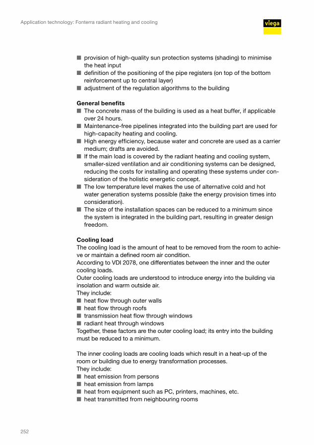
Cooling load The cooling load is the amount of heat to be removed from the room to achie-ve or maintain a defined room air condition.According to VDI 2078, one differentiates between the inner and the outer cooling loads.Outer cooling loads are understood to introduce energy into the building via insolation and warm outside air.They include:
■ heat flow through outer walls ■ heat flow through roofs ■ transmission heat flow through windows ■ radiant heat through windows
Together, these factors are the outer cooling load; its entry into the building must be reduced to a minimum.
The inner cooling loads are cooling loads which result in a heat-up of the room or building due to energy transformation processes.They include:
■ heat emission from persons ■ heat emission from lamps ■ heat from equipment such as PC, printers, machines, etc. ■ heat transmitted from neighbouring rooms
252

Calculation processThe VDI 2078 offers two different calculation processes, a simple and a de-tailed one. They are not used to calculate the room cooling load for any point in time but for a special maximum value.The cooling load of every single room is calculated repeatedly at intervals of one hour on an exemplary day in a particularly hot month (e.g. July 11:00 a.m., 12:00 noon, ... 4:00 p.m., 5:00 p.m. etc.).
To calculate the cooling load of the building, the results of the temperatures of the single rooms measured in hourly intervals are added up (all 11:00 a.m. results of the respective day, all 12:00 noon results, etc. are added up).The highest of all these results is the cooling load of the building.
Control and manifolds In cooling mode, so-called comfort ranges should be defined for regulation of the room temperature. The self-regulation effect of thermally active surfaces can be used as a basis; this means that the energy transport is effected au-tomatically because of the existing differences between the temperatures of the room air and of the surfaces. The building should also be divided into dif-ferent control zones based on utilisation, exposure to insolation, etc. Special attention must be paid to dew point monitoring – in particular of the system components – since they may require diffusion resistant insulation.In heating mode, an automatic system (control) dependent on the outside temperature is required according to Section 14 of EnEV 2014 to reduce and switch off the heat supply and to switch electrical drives on and off. Further-more, overheating of the room due to internal loads must be avoided.
Usually, manifolds can be installed at partitions or in suspended ceilings or raised screed floors subject to the subsequent accessibility of the installation site.
Fonterra Active | General
253

Application technology: Fonterra radiant heating and cooling
Planning
System descriptionFonterra Active is intended specifically for use in concrete ceilings (on top of the bottom reinforcement, up to the central layer).This protected position in the core of the concrete layer ensures maximum freedom of design to meet the architect's or building owner's requirements.
Fonterra Active can ■ be adjusted on site to the requirements of the specific building site; ■ be flexibly connected to a manifold or a zone valve; ■ also be installed in a Tichelmann system with T-pieces.
Fig. 212: Fonterra Active, construction site photo
Features ■ Guaranteed drilling depth thanks to mounting of the pipe register on top of the bottom reinforcement or up to the central layer; thus, independent of taboo zones and partitions
■ Covering the main load ■ Use of oxygen-seal pipes, 17 x 2.0 mm or 20 x 2.0 mm, acc. to DIN 4726 ■ Connection lines are unthreaded upwards or downwards by means of floor lead-in
■ Mounted in the course of formwork or concrete pouring ■ Supply lines can be integrated in the regular ceiling construction ■ Direct manifold connection possible ■ With larger heating circuits, connection can be made by means of T-pieces to a collector pipe laid in the Tichelmann system
Fonterra Active, construction site photo
254
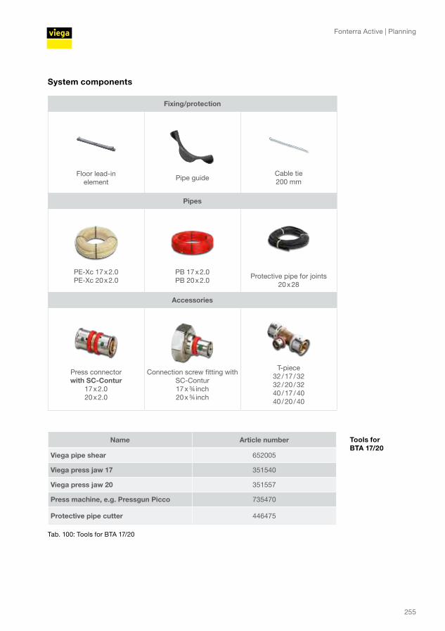
System components
Fixing/protection
Floor lead-in element
Pipe guideCable tie 200 mm
Pipes
PE-Xc 17 x 2.0 PE-Xc 20 x 2.0
PB 17 x 2.0PB 20 x 2.0
Protective pipe for joints20 x 28
Accessories
Press connector with SC-Contur
17 x 2.0 20 x 2.0
Connection screw fitting with SC-Contur 17 x ¾ inch 20 x ¾ inch
T-piece32 / 17 / 3232 / 20 / 3240 / 17 / 4040 / 20 / 40
Name Article number
Viega pipe shear 652005
Viega press jaw 17 351540
Viega press jaw 20 351557
Press machine, e.g. Pressgun Picco 735470
Protective pipe cutter 446475
Tab. 100: Tools for BTA 17/20
Tools for BTA 17/20
Fonterra Active | Planning
255
Application technology: Fonterra radiant heating and cooling
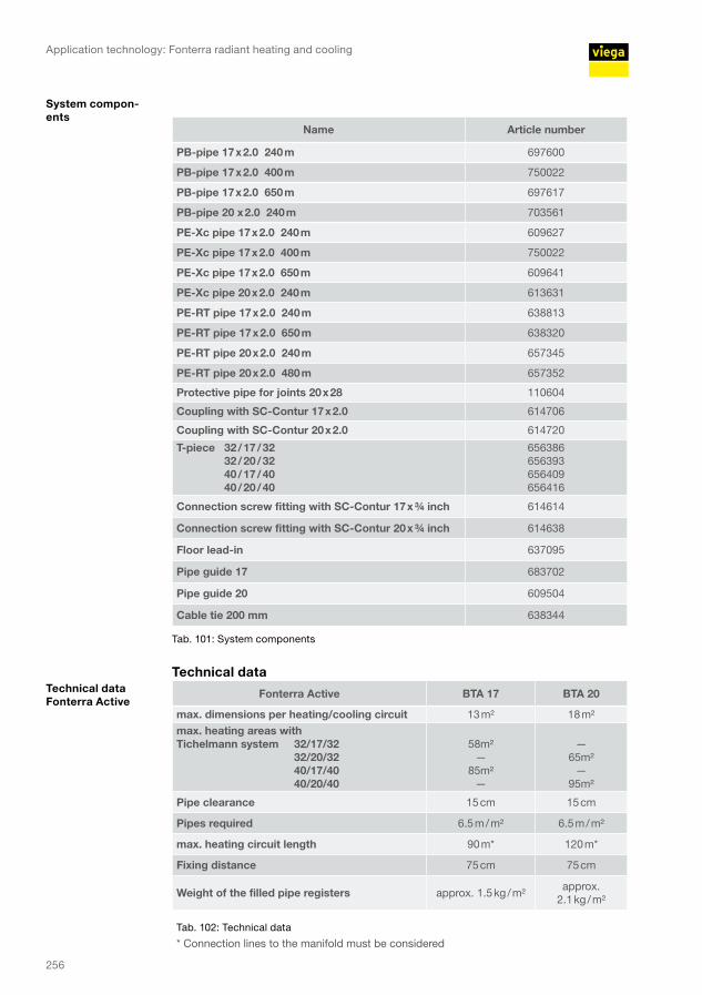
Name Article number
PB-pipe 17 x 2.0 240 m 697600
PB-pipe 17 x 2.0 400 m 750022
PB-pipe 17 x 2.0 650 m 697617
PB-pipe 20 x 2.0 240 m 703561
PE-Xc pipe 17 x 2.0 240 m 609627
PE-Xc pipe 17 x 2.0 400 m 750022
PE-Xc pipe 17 x 2.0 650 m 609641
PE-Xc pipe 20 x 2.0 240 m 613631
PE-RT pipe 17 x 2.0 240 m 638813
PE-RT pipe 17 x 2.0 650 m 638320
PE-RT pipe 20 x 2.0 240 m 657345
PE-RT pipe 20 x 2.0 480 m 657352
Protective pipe for joints 20 x 28 110604
Coupling with SC-Contur 17 x 2.0 614706
Coupling with SC-Contur 20 x 2.0 614720
T-piece 32 / 17 / 32 32 / 20 / 32 40 / 17 / 40 40 / 20 / 40
656386 656393 656409 656416
Connection screw fitting with SC-Contur 17 x ¾ inch 614614
Connection screw fitting with SC-Contur 20 x ¾ inch 614638
Floor lead-in 637095
Pipe guide 17 683702
Pipe guide 20 609504
Cable tie 200 mm 638344
Tab. 101: System components
Technical data
Fonterra Active BTA 17 BTA 20
max. dimensions per heating/cooling circuit 13 m² 18 m²max. heating areas with Tichelmann system 32/17/32
32/20/32 40/17/40 40/20/40
58m²
— 85m²
—
—
65m² —
95m²
Pipe clearance 15 cm 15 cm
Pipes required 6.5 m / m² 6.5 m / m²
max. heating circuit length 90 m* 120 m*
Fixing distance 75 cm 75 cm
Weight of the filled pipe registers approx. 1.5 kg / m²approx.
2.1 kg / m²
Tab. 102: Technical data
* Connection lines to the manifold must be considered
System compon-ents
Technical data Fonterra Active
256
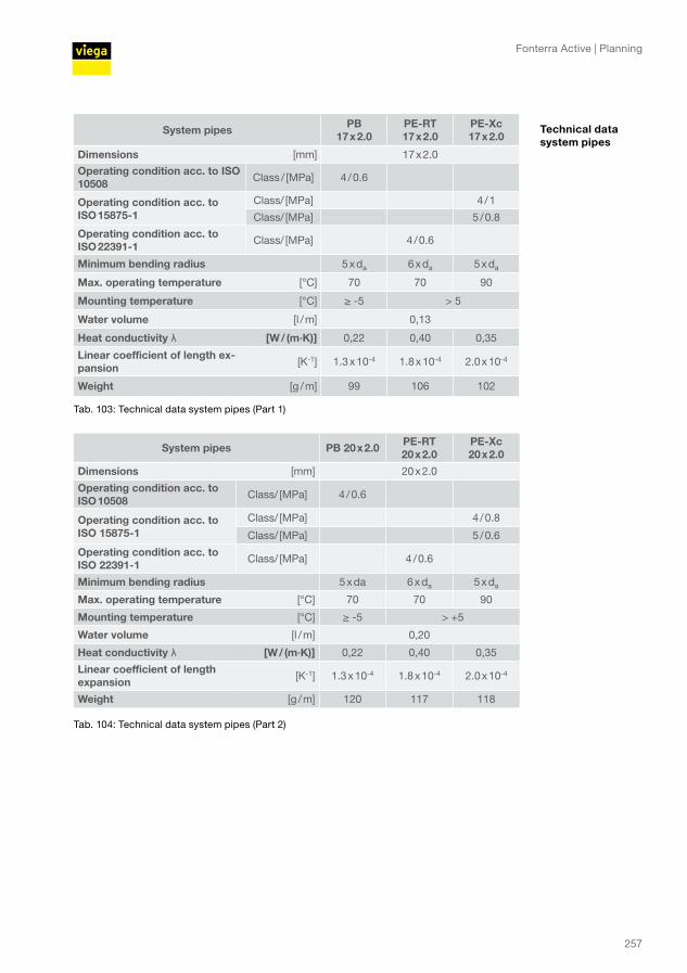
System pipes PB 17 x 2.0
PE-RT 17 x 2.0
PE-Xc 17 x 2.0
Dimensions [mm] 17 x 2.0
Operating condition acc. to ISO 10508 Class / [MPa] 4 / 0.6
Operating condition acc. to ISO 15875-1
Class/ [MPa] 4 / 1
Class/ [MPa] 5 / 0.8
Operating condition acc. to ISO 22391-1 Class/ [MPa] 4 / 0.6
Minimum bending radius 5 x da 6 x da 5 x da
Max. operating temperature [°C] 70 70 90
Mounting temperature [°C] ≥ -5 > 5
Water volume [l / m] 0,13
Heat conductivity λ [W / (m·K)] 0,22 0,40 0,35
Linear coefficient of length ex-pansion [K-1] 1.3 x 10⁻⁴ 1.8 x 10⁻⁴ 2.0 x 10⁻⁴
Weight [g / m] 99 106 102
Tab. 103: Technical data system pipes (Part 1)
System pipes PB 20 x 2.0 PE-RT 20 x 2.0
PE-Xc 20 x 2.0
Dimensions [mm] 20 x 2.0
Operating condition acc. to ISO 10508 Class/ [MPa] 4 / 0.6
Operating condition acc. to ISO 15875-1
Class/ [MPa] 4 / 0.8
Class/ [MPa] 5 / 0.6
Operating condition acc. to ISO 22391-1 Class/ [MPa] 4 / 0.6
Minimum bending radius 5 x da 6 x da 5 x da
Max. operating temperature [°C] 70 70 90
Mounting temperature [°C] ≥ -5 > +5
Water volume [l / m] 0,20
Heat conductivity λ [W / (m·K)] 0,22 0,40 0,35
Linear coefficient of length expansion [K-1] 1.3 x 10⁻⁴ 1.8 x 10⁻⁴ 2.0 x 10⁻⁴
Weight [g / m] 120 117 118
Tab. 104: Technical data system pipes (Part 2)
Technical data system pipes
Fonterra Active | Planning
257
Application technology: Fonterra radiant heating and cooling
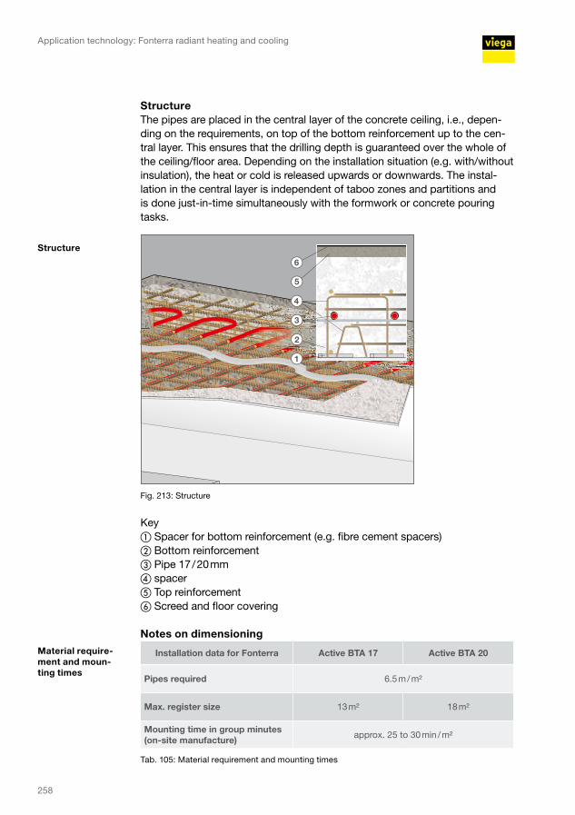
Structure The pipes are placed in the central layer of the concrete ceiling, i.e., depen-ding on the requirements, on top of the bottom reinforcement up to the cen-tral layer. This ensures that the drilling depth is guaranteed over the whole of the ceiling/floor area. Depending on the installation situation (e.g. with/without insulation), the heat or cold is released upwards or downwards. The instal-lation in the central layer is independent of taboo zones and partitions and is done just-in-time simultaneously with the formwork or concrete pouring tasks.
Fig. 213: Structure
Key ① Spacer for bottom reinforcement (e.g. fibre cement spacers)② Bottom reinforcement③ Pipe 17 / 20 mm④ spacer⑤ Top reinforcement⑥ Screed and floor covering
Notes on dimensioning
Installation data for Fonterra Active BTA 17 Active BTA 20
Pipes required 6.5 m / m²
Max. register size 13 m² 18 m²
Mounting time in group minutes (on-site manufacture) approx. 25 to 30 min / m²
Tab. 105: Material requirement and mounting times
Structure
Material require-ment and moun-ting times
258
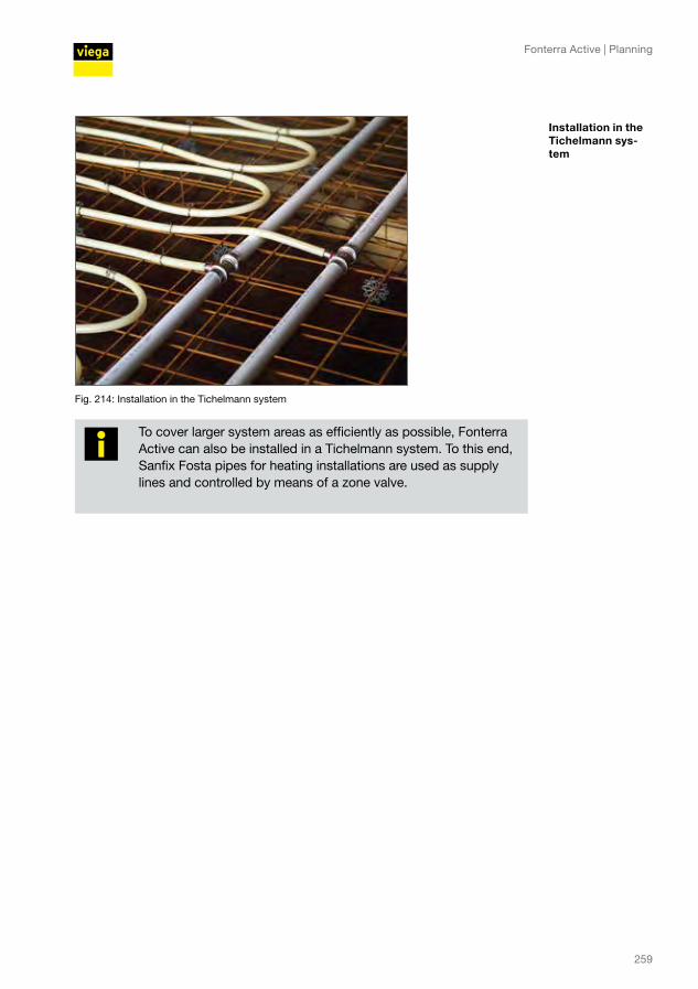
Fig. 214: Installation in the Tichelmann system
To cover larger system areas as efficiently as possible, Fonterra Active can also be installed in a Tichelmann system. To this end, Sanfix Fosta pipes for heating installations are used as supply lines and controlled by means of a zone valve.
Installation in the Tichelmann sys-tem
Fonterra Active | Planning
259

Application technology: Fonterra radiant heating and cooling
Performance dataPerformance of the Fonterra Active with different installation situations
Operating mode Heating at 20 °C
Cooling at 26 °C
Supply temperature /return temperature [°C] 29 / 26 16 / 19mean surface temperature ceiling [°C] approx. 24 approx. 22mean surface temperature floor [°C] approx. 21 approx. 25static performance over ceiling [W / m2] approx. 28 approx. 44static performance over floor [W / m2] approx. 6 approx. 6Total performance of the system [W / m2] approx. 34 approx. 50
Tab. 106: Installation with 25 mm insulation under screed
Fig. 215: Cut with 25 mm insulation
Key ① Floor covering② Screed③ Insulation④ Concrete
Operating mode Heating at 20 °C
Cooling at 26 °C
Supply temperature /return temperature [°C] 29 / 26 16 / 19
mean surface temperature ceiling [°C] approx. 24 approx. 22
mean surface temperature floor [°C] approx. 22 approx. 24
static performance over ceiling [W / m2] approx. 26 approx. 41
static performance over floor [W / m2] approx. 17 approx. 16
Total performance of the system [W / m2] approx. 43 approx. 57
Tab. 107: Installation without insulation
Installation with 25 mm insulation under screed
1
2
3
4
Cut with 25 mm insulation
Installation wit-hout insulation
260
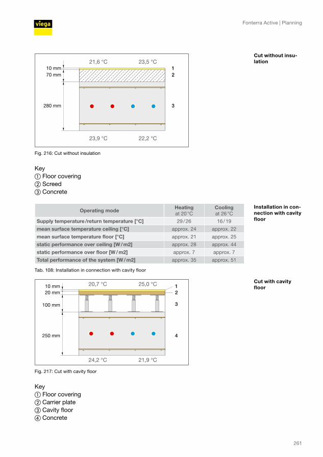
Fig. 216: Cut without insulation
Key ① Floor covering② Screed③ Concrete
Operating mode Heating at 20 °C
Cooling at 26 °C
Supply temperature /return temperature [°C] 29 / 26 16 / 19
mean surface temperature ceiling [°C] approx. 24 approx. 22
mean surface temperature floor [°C] approx. 21 approx. 25
static performance over ceiling [W / m2] approx. 28 approx. 44
static performance over floor [W / m2] approx. 7 approx. 7
Total performance of the system [W / m2] approx. 35 approx. 51
Tab. 108: Installation in connection with cavity floor
Fig. 217: Cut with cavity floor
Key ① Floor covering② Carrier plate③ Cavity floor④ Concrete
12
3
Cut without insu-lation
Installation in con-nection with cavity floor
12
3
4
Cut with cavity floor
Fonterra Active | Planning
261

Application technology: Fonterra radiant heating and cooling
Fig. 218: Pressure loss diagram for Fonterra pipes 17 x 2.0 and 20 x 2.0 mm
Key ① Pressure gradient R in [Pa/m]② Mass flow m in [kg/h] (fluid: water)
Pa/m
kg/h
1
2
Pressure loss diagram for pipes 17 x 2.0 and 20 x 2.0 mm
262
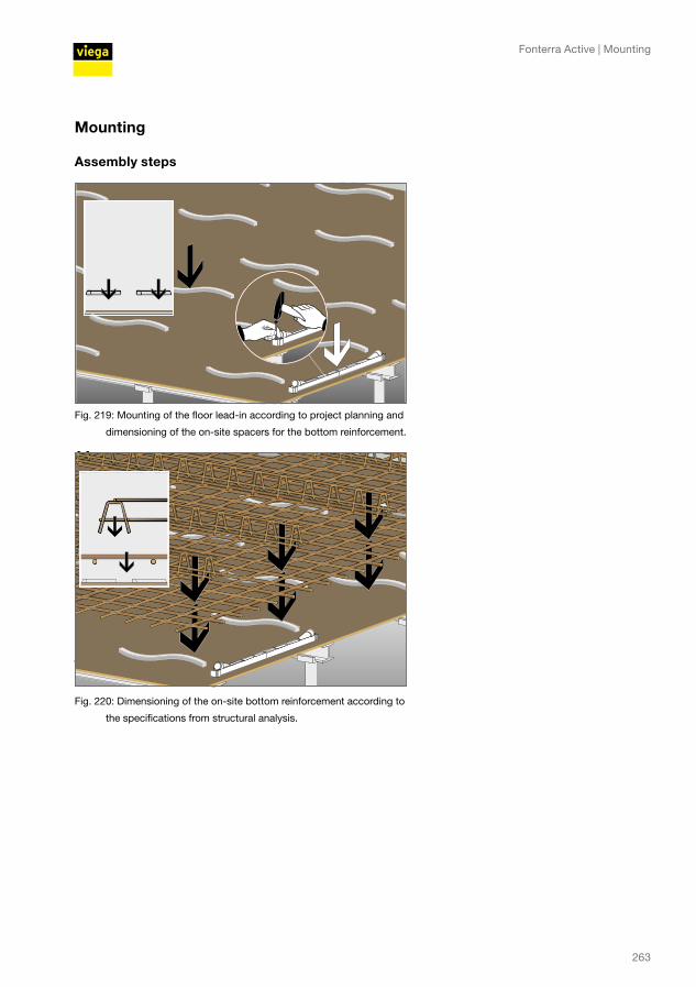
Mounting
Assembly steps
Fig. 219: Mounting of the floor lead-in according to project planning and
dimensioning of the on-site spacers for the bottom reinforcement.
Fig. 220: Dimensioning of the on-site bottom reinforcement according to
the specifications from structural analysis.
Fonterra Active | Mounting
263

Application technology: Fonterra radiant heating and cooling
Fig. 221: Dimensioning of the spacers for receiving the pipelines.
Fig. 222: Installation of the circuits according to project planning and
leading the connection pipes through the floor lead-in.
Fig. 223: Dimensioning of the spacers for receiving the top reinforcement.
264

Fig. 224: Dimensioning of the top reinforcement according to the specifications from structural
analysis.
Final assembly of the floor lead-inAfter stripping the formwork of the ceiling structure, the connection pipes can simply be pulled down from the floor lead-in. To simplify this process for the trade professionals, a tab is provided in the ceiling element which indicates the direction in which the pipe has been pushed in.
Fig. 225: Pulling the connection pipelines from the floor lead-in.
Fonterra Active | Mounting
265

Application technology: Fonterra radiant heating and cooling
Fig. 226: Connecting the Fonterra Active registers to the manifold, flushing he
registers, and commissioning the system after completion of the
building shell
During construction, be sure to avoid any deterioration of the fire protection characteristics of the ceiling and the reinforcements in the ceiling; if necessary, additional measures must be taken. To prevent any carry-over of fire and smoke, the remaining empty pipes must be closed up by filling them completely with Viega fire protection putty (model 4920.9). A calcium silicate plate can be put on top as an additional smoke barrier. Viega recommends to coordinate the design before execution with the person responsible for fire protection and with the appro-ving authority.
Pressure test Before the start of concrete pouring, the system must be checked for leak tightness according to the pressure test records.The pressure defined then must be maintained and documented during the whole concrete pouring process.
266
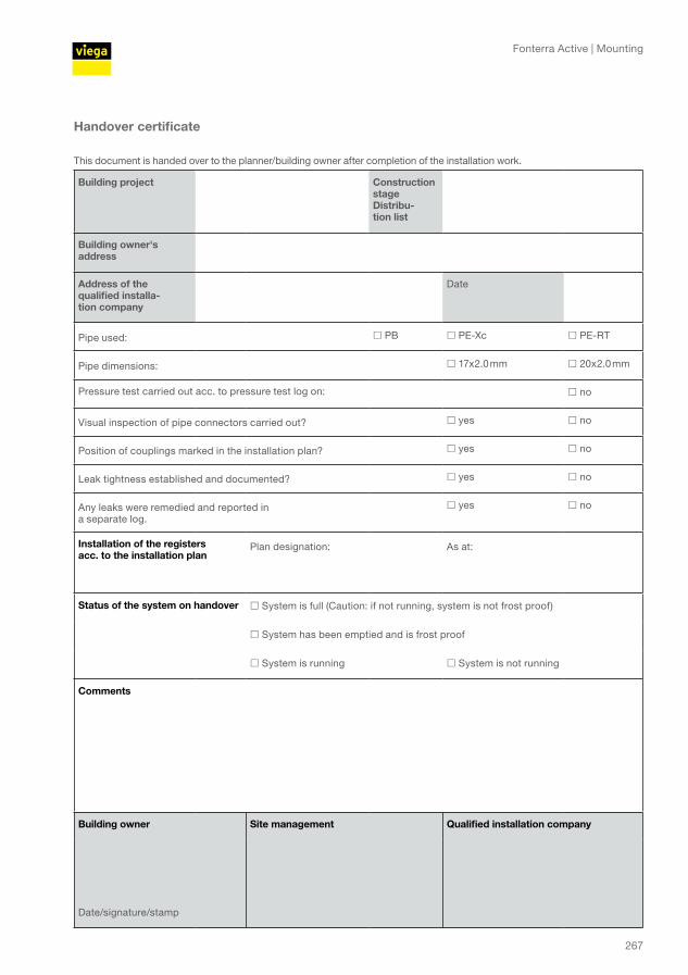
Handover certificate
This document is handed over to the planner/building owner after completion of the installation work.
Building project Construction stage Distribu-tion list
Building owner's address
Address of the qualified installa-tion company
Date
Pipe used: PB PE-Xc PE-RT
Pipe dimensions: 17x2.0 mm 20x2.0 mm
Pressure test carried out acc. to pressure test log on: no
Visual inspection of pipe connectors carried out? yes no
Position of couplings marked in the installation plan? yes no
Leak tightness established and documented? yes no
Any leaks were remedied and reported in a separate log.
yes no
Installation of the registers acc. to the installation plan
Plan designation: As at:
Status of the system on handover System is full (Caution: if not running, system is not frost proof)
System has been emptied and is frost proof
System is running System is not running
Comments
Building owner Site management Qualified installation company
Date/signature/stamp
Fonterra Active | Mounting
267

Application technology: Fonterra radiant heating and cooling
Pressure test
This document must be handed over to the planner/building owner after completed pressure test.
We recommend to retain the document.Building project Construc-
tion stage
manifoldBuilding owner's address
Address of the qualified instal-lation company
Date
Before pouring the concrete, the leak tightness of the heating circuits is tested with water. The leakage test is carried out at the finished but not yet covered pipelines.Notes on the test procedure
■ Fill the system with filtered water and vent it completely.
■ In case of major differences (~10 K) between the ambient temperature and the filling water temperature, wait for 30 minu-
tes after filling the system for the temperatures to adjust.
■ Carry out the leakage test at a pressure of 0.4 MPa (4 bar), max. 0.6 MPa (6 bar). When handing the subsection over to the
subsequent companies and when pouring the concrete, this pressure must be maintained.
■ System units not designed for these pressure levels (e.g. safety valves, expansion vessels etc.) must be exempted from
the test.
■ Visual inspection of the piping system/check per manometer*.
■ Take suitable measures to exclude freezing, for example room heating or addition of anti-freeze to the heating water.
■ If the anti-freeze is not required for normal operation, the system must be cleaned by emptying and flushing with at least
three water exchanges.
■ The water temperature must be kept constant during the test. * Pressure gauges must be used which clearly indicate pressure changes of 0.01 MPa.
Materials used Pipes: 17 x 2.0 mm 20 x 2.0 mm
Pipe connectors: Pressing Clamping
Log of the pressure test
Start of the pressure test: Start pressure: Water temperature [°C]:
End of the pressure test: Final pressure: Water temperature [°C]:
Visual inspection of pipe connectors carried out? yes no
Position of couplings marked in the installation plan? yes no
Leak tightness was established, no permanent form changes identified in any component?
yes no
Has the operating pressure been set on system handover? yes no
Comments
Building owner Site management Qualified installation company
Date/signature/stamp
268

INT ∙ 709 365 ∙ 2018-05 ∙ VPN 170369
Viega Technology GmbH & Co. KGViega Platz 157439 AttendornGermany
Phone +49 (0) 2722 61-0
viega.com


![*HEOlVHXQWHUVW W]WH +HL]N|USHU … · VDI 2078. Grundlagen Kühlleistungen Die Kühlleistungen der Unterflurkonvektoren Ascotherm eco wurden nach E DIN EN 16430 „Gebläseunterstützte](https://static.fdocuments.in/doc/165x107/5ba0684a09d3f2c2598cb957/heolvhxqwhuvw-wwh-hlnushu-vdi-2078-grundlagen-kuehlleistungen-die-kuehlleistungen.jpg)


![*HEOlVHXQWHUVW W]WH +HL]N|USHU .RQYHNWRUHQ XQG ... · VDI 2078. Grundlagen Kühlleistungen Die Kühlleistungen der Unterflurkonvektoren Ascotherm eco wurden nach E DIN EN 16430 „Gebläseunterstützte](https://static.fdocuments.in/doc/165x107/60e5605f3f84fe123e3ceefa/heolvhxqwhuvw-wwh-hlnushu-rqyhnwruhq-xqg-vdi-2078-grundlagen-khlleistungen.jpg)