Volume 2, Issue 8, August 2013 ISSN 2319 - 4847 Edged ... Journal of Application or Innovation in...
5
International Journal of Application or Innovation in Engineering & Management (IJAIEM) Web Site: www.ijaiem.org Email: [email protected], [email protected] Volume 2, Issue 8, August 2013 ISSN 2319 - 4847 Volume 2, Issue 8, August 2013 Page 86 ABSTRACT In this Paper we analysied about Edge detection characteristics and different ways of finding an edge in an image and we have implemented Sobel operator way to find the edge detection in an image. Here we have written the core processor Microblaze is designed in VHDL (VHSIC hardware description language), implemented using XILINX ISE 10.1 Design suite the algorithm is written in system C Language and tested in SPARTAN-3 FPGA kit by interfacing a test circuit with the PC using the RS232 cable. The test results are seen to be satisfactory. The area taken and the speed of the algorithm are also evaluated. Keywords: UART, VHDL,Softcore, Microblaze, Edge detection,Sobel Operator 1. INTRODUCTION Edge detection refers to the method of distinctive and locating sharp discontinuities in a picture. The discontinuities square measure abrupt changes in element intensity that characterize boundaries of objects during a scene. Classical strategies of edge detection involve convolving the image with associate operator (a 2-D filter), that is built to be sensitive to massive gradients within the image whereas returning values of zero in uniform regions. there's a particularly sizable amount of edge detection operators accessible, every designed to be sensitive to bound styles of edges. Variables concerned within the choice of a Edge detection operator include: 1.1 Edge orientation: The pure mathematics of the operator determines a characteristic direction within which it's most sensitive. 1.2 Noise environment: Edge detection is tough in clattery pictures, since each the noise and therefore the edges contain high-frequency content. tries to scale back the noise end in blurred and distorted edges. Operators used on clattery pictures area unit usually larger in scope, in order that they will average enough information to discount localized clattery pixels. This leads to less correct localization of the detected edge. 1.3 Edge structure: Not all edges involve a step modification in intensity. Effects like refraction or poor focus may result in objects with boundaries outlined by a gradual modification in intensity. The operator has to be chosen to be conscious of such a gradual modification in those cases. Newer wavelet-based techniques really characterize the character of the transition for every approach order to tell apart, for instance, edges related to hair from edges related to a face.There square measure many ways to perform edge detection. However, the bulk of various ways is also classified into 2 categories 1.4 Gradient: The gradient technique detects the sides by yearning for the utmost and minimum within the differential coefficient of the image. 1.5 Laplacian:The Laplacian technique searches for zero crossings within the second by-product of the image to seek out edges. 2.EDGE DETECTION TECHNIQUES Majorly Edge detection can be done using three operators Prewitt operator Sobel Operator Canny Opeartor In this Paper we are going to implement Sobel operator for finding an Edge detected image. Sobel Operator The operator consists of a pair of 3×3 convolution kernels as shown in Figure 1. One kernel is simply the other rotated by 90°. Edged Detection Algorithm implemented in Sobel Operator in hardware M.kalyani, 1 K.Amarnath 2 1 PG Student, VRS&YRN College of Engineering and Technology, From JNTUK, affiliated to AICTE, Chirala. 2 Professor,HOD, VRS&YRN College of Engineering and Technology, From JNTUK, affiliated to AICTE, Chirala
Transcript of Volume 2, Issue 8, August 2013 ISSN 2319 - 4847 Edged ... Journal of Application or Innovation in...

International Journal of Application or Innovation in Engineering & Management (IJAIEM) Web Site: www.ijaiem.org Email: [email protected], [email protected]
Volume 2, Issue 8, August 2013 ISSN 2319 - 4847
Volume 2, Issue 8, August 2013 Page 86
ABSTRACT
In this Paper we analysied about Edge detection characteristics and different ways of finding an edge in an image and we have implemented Sobel operator way to find the edge detection in an image. Here we have written the core processor Microblaze is designed in VHDL (VHSIC hardware description language), implemented using XILINX ISE 10.1 Design suite the algorithm is written in system C Language and tested in SPARTAN-3 FPGA kit by interfacing a test circuit with the PC using the RS232 cable. The test results are seen to be satisfactory. The area taken and the speed of the algorithm are also evaluated. Keywords: UART, VHDL,Softcore, Microblaze, Edge detection,Sobel Operator 1. INTRODUCTION Edge detection refers to the method of distinctive and locating sharp discontinuities in a picture. The discontinuities square measure abrupt changes in element intensity that characterize boundaries of objects during a scene. Classical strategies of edge detection involve convolving the image with associate operator (a 2-D filter), that is built to be sensitive to massive gradients within the image whereas returning values of zero in uniform regions. there's a particularly sizable amount of edge detection operators accessible, every designed to be sensitive to bound styles of edges. Variables concerned within the choice of a Edge detection operator include: 1.1 Edge orientation: The pure mathematics of the operator determines a characteristic direction within which it's most sensitive. 1.2 Noise environment: Edge detection is tough in clattery pictures, since each the noise and therefore the edges contain high-frequency content. tries to scale back the noise end in blurred and distorted edges. Operators used on clattery pictures area unit usually larger in scope, in order that they will average enough information to discount localized clattery pixels. This leads to less correct localization of the detected edge. 1.3 Edge structure: Not all edges involve a step modification in intensity. Effects like refraction or poor focus may result in objects with boundaries outlined by a gradual modification in intensity. The operator has to be chosen to be conscious of such a gradual modification in those cases. Newer wavelet-based techniques really characterize the character of the transition for every approach order to tell apart, for instance, edges related to hair from edges related to a face.There square measure many ways to perform edge detection. However, the bulk of various ways is also classified into 2 categories 1.4 Gradient: The gradient technique detects the sides by yearning for the utmost and minimum within the differential coefficient of the image. 1.5 Laplacian:The Laplacian technique searches for zero crossings within the second by-product of the image to seek out edges. 2.EDGE DETECTION TECHNIQUES Majorly Edge detection can be done using three operators
Prewitt operator Sobel Operator Canny Opeartor
In this Paper we are going to implement Sobel operator for finding an Edge detected image. Sobel Operator The operator consists of a pair of 3×3 convolution kernels as shown in Figure 1. One kernel is simply the other rotated by 90°.
Edged Detection Algorithm implemented in Sobel Operator in hardware
M.kalyani,1 K.Amarnath2
1PG Student, VRS&YRN College of Engineering and Technology, From JNTUK, affiliated to AICTE, Chirala.
2Professor,HOD, VRS&YRN College of Engineering and Technology,
From JNTUK, affiliated to AICTE, Chirala
International Journal of Application or Innovation in Engineering & Management (IJAIEM) Web Site: www.ijaiem.org Email: [email protected], [email protected]
Volume 2, Issue 8, August 2013 ISSN 2319 - 4847
Volume 2, Issue 8, August 2013 Page 87
These kernels are designed to respond maximally to edges running vertically and horizontally relative to the pixel grid, one kernel for each of the two perpendicular orientations. The kernels can be applied separately to the input image, to produce separate measurements of the gradient component in each orientation (call these Gx and Gy). These can then be combined together to find the absolute magnitude of the gradient at each point and the orientation of that gradient. The gradient magnitude is given by:
Typically, an approximate magnitude is computed using:
which is much faster to compute.
The angle of orientation of the edge (relative to the pixel grid) giving rise to the spatial gradient is given by:
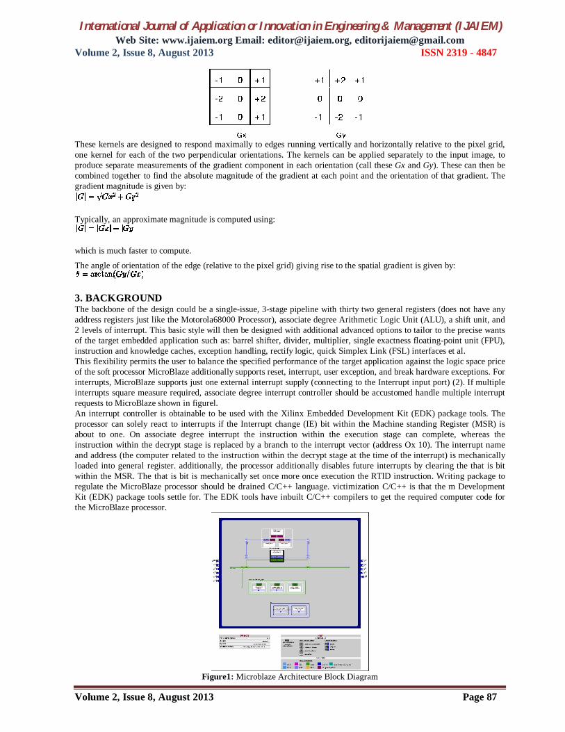
3. BACKGROUND The backbone of the design could be a single-issue, 3-stage pipeline with thirty two general registers (does not have any address registers just like the Motorola68000 Processor), associate degree Arithmetic Logic Unit (ALU), a shift unit, and 2 levels of interrupt. This basic style will then be designed with additional advanced options to tailor to the precise wants of the target embedded application such as: barrel shifter, divider, multiplier, single exactness floating-point unit (FPU), instruction and knowledge caches, exception handling, rectify logic, quick Simplex Link (FSL) interfaces et al. This flexibility permits the user to balance the specified performance of the target application against the logic space price of the soft processor MicroBlaze additionally supports reset, interrupt, user exception, and break hardware exceptions. For interrupts, MicroBlaze supports just one external interrupt supply (connecting to the Interrupt input port) (2). If multiple interrupts square measure required, associate degree interrupt controller should be accustomed handle multiple interrupt requests to MicroBlaze shown in figurel. An interrupt controller is obtainable to be used with the Xilinx Embedded Development Kit (EDK) package tools. The processor can solely react to interrupts if the Interrupt change (IE) bit within the Machine standing Register (MSR) is about to one. On associate degree interrupt the instruction within the execution stage can complete, whereas the instruction within the decrypt stage is replaced by a branch to the interrupt vector (address Ox 10). The interrupt name and address (the computer related to the instruction within the decrypt stage at the time of the interrupt) is mechanically loaded into general register. additionally, the processor additionally disables future interrupts by clearing the that is bit within the MSR. The that is bit is mechanically set once more once execution the RTlD instruction. Writing package to regulate the MicroBlaze processor should be drained C/C++ language. victimization C/C++ is that the m Development Kit (EDK) package tools settle for. The EDK tools have inbuilt C/C++ compilers to get the required computer code for the MicroBlaze processor.
Figure1: Microblaze Architecture Block Diagram

International Journal of Application or Innovation in Engineering & Management (IJAIEM) Web Site: www.ijaiem.org Email: [email protected], [email protected]
Volume 2, Issue 8, August 2013 ISSN 2319 - 4847
Volume 2, Issue 8, August 2013 Page 88
Due to the advancement within the fabrication technology and therefore the increase within the density of logic blocks on FPGA, the utilization of FPGA isn't restricted any longer to debugging and prototyping digital electronic circuits. attributable to the large correspondence doable on FPGA and therefore the increasing density of logic blocks, it's getting used currently as a replacement to ASIC solutions in a very few applications wherever the time to plug is important and conjointly entire embedded processor systems area unit enforced on these devices with soft core processors embedded within the system. With the advancement of Field Programmable Gate Arrays (FPGAs), like addition of considerable amounts of memory, a brand new trend has emerged within the style community to implement the microprocessors on the FPGAs. These reasonably processors enforced on a reconfigurable material area unit referred to as soft-processors or soft cores because the style of the microchip is on the market within the type of computer code bitstream ost popular methodology by the general public and is that the format that the Xilinx Embedded which may be downloaded on FPGA by the user. The users have the selection of choosing the resources on the processor and therefore the memory hierarchy. Soft cores area unit designed to fulfill minimum performance specifications over a variety of technology implementations, despite the fact that core performance varies across technologies. Soft cores area unit technology freelance and need solely simulation and temporal order verification when synthesized to a target technology. This reduces {the style|the planning|the look} cycle development time by a serious issue as compared to the event cycle for a tough core processor and has the advantage of customizing the soft core design for a particular application. presently there area unit variety of soppy cores out there within the markets that area unit developed by giants within the field of reconfigurable devices like Xilinx. Xilinx has their own design named MicroBlaze during this arena and that they have conjointly ported the favored PowerPC design to be used in embedded systems. These soft cores area unit out there within the type of synthesized alpha-lipoprotein modules logic gate level netlists. System designers will plant these cores into their styles and optionally add peripherals to the core. 4. EXPERIMENTAL SETUP A. Xilinx Platform Studio The Xilinx Platform Studio (XPS) is that the development setting or graphical user interface used for planning the hardware portion of your embedded processor system. B. Embedded Development Kit Xilinx Embedded Development Kit (EDK) is associate degree integrated software package tool suite for developing embedded systems with Xilinx MicroBlaze and PowerPC CPUs. EDK includes a range of tools associate degreed applications to help the designer to develop associate degree embedded system right from the hardware creation to final implementation of the system on an FPGA. System style consists of the creation of the hardware and software package parts of the embedded processor system and therefore the creation of a verification element is facultative. A typical embedded system style project involves: hardware platform creation, hardware platform verification (simulation), software package platform creation, software package application creation, and software package verification. BaseSystem Builder is that the wizard that's accustomed mechanically generate a hardware platform in keeping with the user specifications that's defmed by the MHS (Microprocessor Hardware Specification) file. The MHS file defines the system design, peripherals and embedded processors]. The Platform Generation tool creates the hardware platform victimization the MHS file as input. The software package platform is defmed by MSS (Microprocessor software package Specification) file that defines driver and library customization parameters for peripherals, processor customization parameters, normal one hundred ten devices, interrupt handler routines, and different software package connected routines. The MSS file is associate degree input to the Library Generator tool for personalisation of drivers, libraries and interrupts handlers
. Figure2: Embedded Development Kit Design Flow
International Journal of Application or Innovation in Engineering & Management (IJAIEM) Web Site: www.ijaiem.org Email: [email protected], [email protected]
Volume 2, Issue 8, August 2013 ISSN 2319 - 4847
Volume 2, Issue 8, August 2013 Page 89
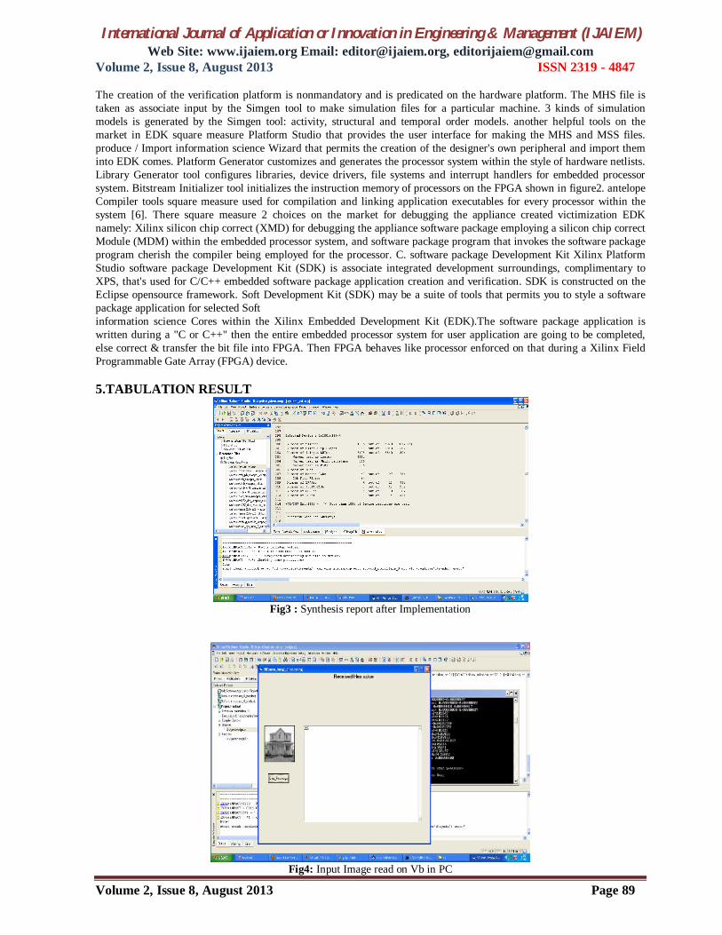
The creation of the verification platform is nonmandatory and is predicated on the hardware platform. The MHS file is taken as associate input by the Simgen tool to make simulation files for a particular machine. 3 kinds of simulation models is generated by the Simgen tool: activity, structural and temporal order models. another helpful tools on the market in EDK square measure Platform Studio that provides the user interface for making the MHS and MSS files. produce / Import information science Wizard that permits the creation of the designer's own peripheral and import them into EDK comes. Platform Generator customizes and generates the processor system within the style of hardware netlists. Library Generator tool configures libraries, device drivers, file systems and interrupt handlers for embedded processor system. Bitstream Initializer tool initializes the instruction memory of processors on the FPGA shown in figure2. antelope Compiler tools square measure used for compilation and linking application executables for every processor within the system [6]. There square measure 2 choices on the market for debugging the appliance created victimization EDK namely: Xilinx silicon chip correct (XMD) for debugging the appliance software package employing a silicon chip correct Module (MDM) within the embedded processor system, and software package program that invokes the software package program cherish the compiler being employed for the processor. C. software package Development Kit Xilinx Platform Studio software package Development Kit (SDK) is associate integrated development surroundings, complimentary to XPS, that's used for C/C++ embedded software package application creation and verification. SDK is constructed on the Eclipse opensource framework. Soft Development Kit (SDK) may be a suite of tools that permits you to style a software package application for selected Soft information science Cores within the Xilinx Embedded Development Kit (EDK).The software package application is written during a "C or C++" then the entire embedded processor system for user application are going to be completed, else correct & transfer the bit file into FPGA. Then FPGA behaves like processor enforced on that during a Xilinx Field Programmable Gate Array (FPGA) device. 5.TABULATION RESULT
Fig3 : Synthesis report after Implementation
Fig4: Input Image read on Vb in PC
International Journal of Application or Innovation in Engineering & Management (IJAIEM) Web Site: www.ijaiem.org Email: [email protected], [email protected]
Volume 2, Issue 8, August 2013 ISSN 2319 - 4847
Volume 2, Issue 8, August 2013 Page 90
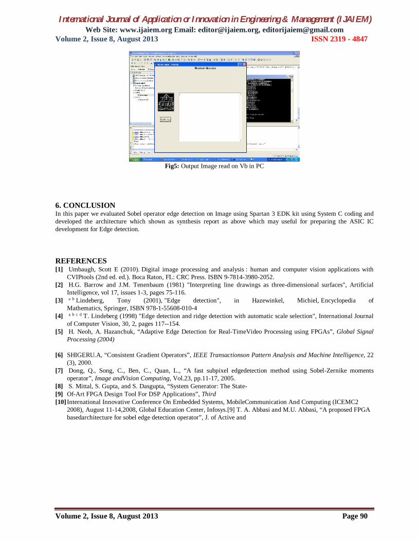
Fig5: Output Image read on Vb in PC
6. CONCLUSION In this paper we evaluated Sobel operator edge detection on Image using Spartan 3 EDK kit using System C coding and developed the architecture which shown as synthesis report as above which may useful for preparing the ASIC IC development for Edge detection. REFERENCES [1] Umbaugh, Scott E (2010). Digital image processing and analysis : human and computer vision applications with
CVIPtools (2nd ed. ed.). Boca Raton, FL: CRC Press. ISBN 9-7814-3980-2052. [2] H.G. Barrow and J.M. Tenenbaum (1981) "Interpreting line drawings as three-dimensional surfaces", Artificial
Intelligence, vol 17, issues 1-3, pages 75-116. [3] a b Lindeberg, Tony (2001), "Edge detection", in Hazewinkel, Michiel, Encyclopedia of
Mathematics, Springer, ISBN 978-1-55608-010-4 [4] a b c d T. Lindeberg (1998) "Edge detection and ridge detection with automatic scale selection", International Journal
of Computer Vision, 30, 2, pages 117--154. [5] H. Neoh, A. Hazanchuk, “Adaptive Edge Detection for Real-TimeVideo Processing using FPGAs”, Global Signal
Processing (2004)
[6] SHIGERU.A, “Consistent Gradient Operators”, IEEE Transactionson Pattern Analysis and Machine Intelligence, 22 (3), 2000.
[7] Dong, Q., Song, C., Ben, C., Quan, L., “A fast subpixel edgedetection method using Sobel-Zernike moments operator”, Image andVision Computing, Vol.23, pp.11-17, 2005.
[8] S. Mittal, S. Gupta, and S. Dasgupta, “System Generator: The State- [9] Of-Art FPGA Design Tool For DSP Applications”, Third [10] International Innovative Conference On Embedded Systems, MobileCommunication And Computing (ICEMC2
2008), August 11-14,2008, Global Education Center, Infosys.[9] T. A. Abbasi and M.U. Abbasi, “A proposed FPGA basedarchitecture for sobel edge detection operator”, J. of Active and