VOLTERRA’ S SOLUTION OF THE WAVE EQUATION ‘ AS APPLIED …
28
-- s..- .. -- _.. I.- REPORT No. 889 ), VOLTERRA’S SOLUTION OF THE WAVE EQUATION ‘AS APPLIED TO THREE-DIMENSIONAL SUPERSONIC AIRFOIL PROBLEMS BY MAX. A.HEASLET,~~ARV~~~D LoMAx, and ARTtiuR L JONli& --- _. _. , . -^ .,,__. ._ _.. -.. _ ._ 1947 For aale by the Superintendent of Documen(s. U. S. Government Printing OIfxce. Waahinglon~25. D. C. - - - - L - - - - - Price 20 cents
Transcript of VOLTERRA’ S SOLUTION OF THE WAVE EQUATION ‘ AS APPLIED …

-- s..- . . -- _.. I.-
REPORT No. 889
),
VOLTERRA’S SOLUTION OF THE WAVE EQUATION ‘AS APPLIED TO THREE-DIMENSIONAL
SUPERSONIC AIRFOIL PROBLEMS
BY MAX. A.HEASLET,~~ARV~~~D LoMAx, and ARTtiuR L JONli& --- _. _. , .
-^ .,,__. ._ _.. -.. _ ._
1947
For aale by the Superintendent of Documen(s. U. S. Government Printing OIfxce. Waahinglon~25. D. C. - - - - L - - - - - Price 20 cents

W g
m I
S St0 G b c A
v
P
L
D
DO
Df
8
.C
AERONAUTIC SYMBOLS ‘1. FUNDAMENTAL AND DERIVED UNITS
Metric ‘. English
Symbol unit
I AbsP- unit .-
Power,--i-- P Speed __--_-- V
horsepower (metric)~- _ _ _ _ _ _ _ &..-- _ hqrsepower- _ _ _ __ _____ kilometers per hour ------, miles per hour- _ _ _____ meters per second- _ ___-_ mps feet per second ________
2. GEtiERfi SYMBOLS
ft (0; qli) set ,(or hr) ,Ib .
1. hI,
g:”
Standard acceleration of -&avity=9.80665 m/s’ : p’ Weight=mg Einematic viscosity
Density (mass per -unit volume) ’ Standard density of dry air, 0.12497 kg-m-*-s2 at 15’ C or 32.1740 it&e?
&ass,!c .: . 1. and 760 mm; or.0.002378 lb-ft-* set’ SpecXc weight of “standard” air, 1.2255 kg/ma or
Moment! of-- inertia=m!?. (Indicate axis. of 0.07651 lb/cu ft ’ ~*‘.’ “--- -radius.of gyration k bi proper subscript:)
Coefficient of viscosity : S. AERODYNAMIC SYMBOLk
Area Area of wing Gap Span Chord Aspect ratio, i True air speed
. Go Angle of setting of win&I (relative to thrust line) . *1 y$e)of stabilizer settmg (relative to thrust
& Resultant moment P Resultant angular velocity
R Reynolds number, p$ where I is a linear dimen- -’
. @-name press’ure, 2~ lvs
Lift, absolute coefficient O!=$
Drag, absolute coefficient OD=$
Pro6l.e drag, absolute coefficient CQ,=$
Induced drag, absolute coefficient CB1=g
Parasite drag, absolute coefficient C=,=K~
Cr&-wind force, absolute coefficient Oc=$,
sion (e.g., for a.n airfoil of 1.0 ft chord, 100 mph, standard pressure at 15’ C, the corresponding Reynolds number is 935,400; or for an airfoil of 1.0 m chord, 100 ,mps, the corresponding : Reynolds number is 6,865,OOO)
Angle of attack Angle of downwash Angle of attack, infinite aspect ratio Angle of attack, induced Anglo of attack, absolute (measured from zero-
lift po&ion) Flight-path angle
REPORT No.889
VOLTERRA’S SOLUTION OF THE WAVE EQUATION AS APPLIED TO THREE-DIMENSIONAL
SUPERSONIC AIRFOIL PROBLEMS
By MAX. A. HEASLET, HARVARD LOMAX, and ARTHUR L. JONES
Ames Aeronautical Laboratory Moffett Field, Calif.
I
1) - ..-.-.-.-.- ._... --
National Advisory Committee for Aeronautics Headquarters, 1724 F Street NW, Washington 25, D. C.
Created by act of Congress approved March 3, 1915, for the supervision and direction of the scientific study of the problems of flight (U. S. Code, title 49, sec. 241). Its membership was increased to 15 by act approved March 2, 1929. The members are appointed by the President, and serve as such without compensation.
JEROME C. HUNSAKER, SC. D., Cambridge, Mass., Chairman
ALEXANDER WETMORE, SC. D., Secretary, Smithsonian Institution, Vice Chairman
HON. JOHN R. ALISON, Assistant Secretary of Commerce. VANNEVAR BUSH, SC. D., Chairman, Research and Development
Board, Department of National Defense. EDWARD U. CONDON, PH. D., Director, Kational Bureau of
Standards. DONALD B. DUNCAN, Vice Admiral, Deputy Chief of h’aval
Operations (Air). R. M. HAZEN, B. S., Chief Engineer, Allison Division, General
Motors Corp. WILLIAM LITTLEWOOD, M. E., Vice President, Engineering,
American Airlines System. THEODORE C. LONNQUEST, Rear Admiral, Assistant Chief for
Research and Development, Bureau of Aeronautics, Kavy Department.
EDWARD M. POWERS, Major Gene:;al, United States Air Force, Deputy Chief of Staff, Materiel.
ARTHUR E. RAYMOND, M. S., Vice President, Engineering, Douglas Aircraft Co.
FRANCIS W. REICHELDERFER, SC. D., Chief, United States Weather Bureau.
CARL SPAATZ, General, Chief of Staff, United States Air Force. ORVILLE WRIQHT, SC. D., Dayton, Ohio. THEODORE P. WRIGHT, SC. D., Administrator of Civil Aero-
nautics, Department of Commerce.
HUGH L. DRYDEN, PH. D., Director of Aeronautical Research JOHN F. VICTORY, LLM., Executive Secretary
JOHN W. CRO~LEY, JR., B. S., Associate Director of Aeronautical Research E. H. CHAMBERLIN, Executive Oficer
HENRY J. E. REID, SC. D., Director, Langley Memorial Aeronautical Laboratory, Langley Field, Va.
SMITH J. DEFRANCE, B. S., Director Ames Aeronautical Laboratory, Moffett Field, Calif.
EDWARD R. SHARP, LL. B., Director, Flight Propulsion Research Laboratory, Cleveland Airport, Cleveland, Ohio
TECHNICAL COMMITTEES
AERODYNAMICS OPERATING PROBLEMS POWER PLANTS FOR AIRCRAFT SELF-PROPELLED GUIDED MISSILES AIRCRAFT CONSTRUCTION INDUSTRY CONSULTING
Coordination of Research Needs of Military and Civil Aviation Preparation of Research Programs
Allocation of Problems Prevention of Duplication
Consideration of Inventions
LANGLEY R~EMORIAL AERONAUTICAL LABORATORY, AMES AERONAUTICAL LABORATORY, Langley Field, Va. Moffett Field, Calif.
FLIGHT PROPULSION RESEARCH LABORATORY, Cleveland Airport, Cleveland, Ohio
Conduct, under unified control, for all agencies, of scientific research on the fundamental problems of flight
OFFICE OF AERONAUTICAL INTELLIGENCE, Washington, D. C.
Collection, classification, compilation, and dissemination of scientific and technical information on aeronautics
II
_ _ . _. . _ ..- - _ . . . _. _ - . II
REPORT No. 889
VOLTiitiliA’S SOLUTION OF THE WAVE EQUATION AS APPLIED TO THREE-DIMENSIONAL SUPERSONIC AIRFOIL PROBLEMS
By MAX. A. HEASLET, HARVARD LOMAX, and ARTHUR L. JONES
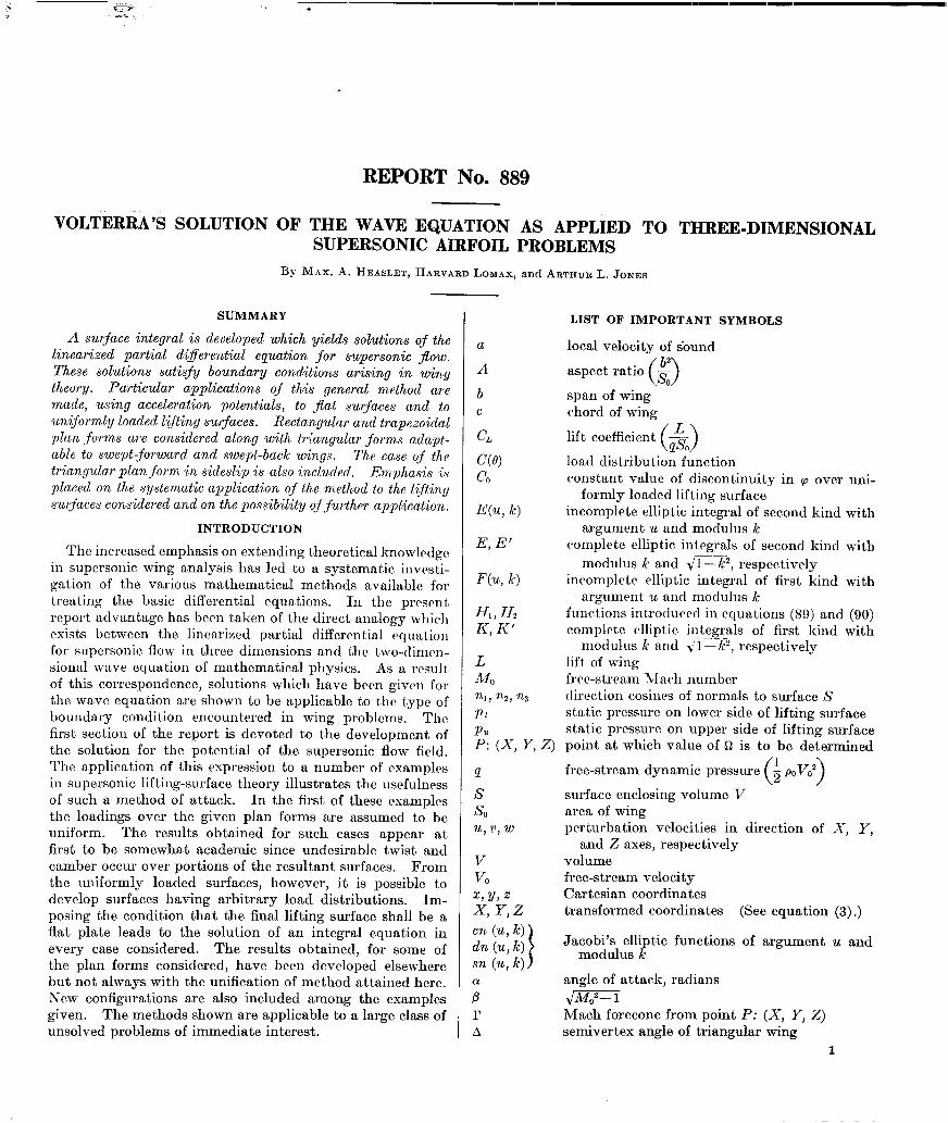
SUMMARY LIST OF IMPORTANT SYMBOLS
A surface integral is developed which yields solutions qf the linearized partial diIerentia1 equation for supersonic sow. These solutions satisfy boundary conditions arising in wing theory. Particular applications of this general method are made, using acceleration potentials, to flat surfaces and to uniformly loaded lifting surfaces. Rectangular and trapezoidal plan -forms are considered along with triangular forms adapt- able to swept-forward and swept-back wings. The case of the triangular plan form in sideslip is also included, Emphasis is placed on the systematic application of the method to the liftincg surfaces considered and on the possibility of further application..
a
A
local velocity of sound
b c
aspect rat,io b2 0 RI span of wing chord of wing
INTRODUCTION
The increased emphasis on extending theoretical knowledge in supersonic wing analysis has led to a systematic invcsti- gation of the various mathematical methods available for treating the basic differential equations. In the present report advantage has been taken of the direct analogy which exists between the linearized partial differential equation for supersonic flow in three dimensions and the two-dimcn- sional wave equation of mathematical physics. As a result of this correspondence, solutions which have been given for the wave equation are shown to be applicable to the type of boundary condition encountered in wing problems. The first section of the report is devoted to the development of the solution for the potential of the supersonic flow field. The application of this expression to a number of examples in supersonic lifting-surface theory illustrates the usefulness of such a method of attack. In the first of these examples the loadings over the given plan forms are assumed to be uniform. The results obtained for such cases appear at first to be somewhat academic since undesirable twist and camber occur over portions of the resultant surfaces. From the uniformly loaded surfaces, however, it is possible to develop surfaces having arbitrary load distributions. Im- posing the condition that the final lifting surface shall be a flat plate leads to the solution of an integral equation in every case considered. The results obtained, for some of the plan forms considered, have been developed elsewhere but not always with the unification of method attained here. New configurations are also included among the examples given. The methods shown are applicable to a large class of unsolved problems of immediate interest.
c(e) CO
E(u, k)
E, E’
- lift coefficient $
( > 0 load distribution function constant value of discontinuity in cp over uni-
formly loaded lifting surface incomplete elliptic integral of second kind with
argument u and modulus k complete elliptic integrals of second kind with
F(u, 4
f-f,, Hz K, K’
L Ml nl, n.2, n3 Pl PU P: (X, Y, z)
moclulus k and 41 -k2, respectively incomplete elliptic integral of first kind with
argument u and modulus k functions introducccl in equations (89) and (90) complete elliptic integrals of first kind with
modulus k and t/l- k2, respectively lift of wing frrc-stream $1 a& number direction cosines of normals to surface S static pressure on lower side of lifting surface static pressure on upper side of lifting surface point at which value of Q is to be determined
P S SO u, v, w
free-stream dynamic pressure (i p,V02)
surface enclosing volume V area of wing perturbation velocities in direction of X, Y,
V VO X,Y,Z x y,z en (u, W dn (u, k) 8% (u, k)
; r A
and Z axes, respectively volume free-stream velocity Cartesian coordinates transformed coordinates (See equation (3) .)
Jacobi’s elliptic functions of argument u and modulus k
angle of attack, radians &iQ? Mach forecone from point P: (X, Y, Z) semivertex angle of triangular wing
1

REPORT NO. 88!?-NATIONAL ADVISORY COMMITTEE FOR AERONAUTICS
pressure differential (p I-p,) angle measured from X axis conical flow coordinate (See equations (27)
and (30).) p tan 6 Jacobi’s theta function cylinder of infinitesimal radius enclosing axis
of forecone r surface at which stream enters induced field of
wing angle of sideslip
Mach angle of the free stream (
p=arc sin ,2)1- 0 >
direction cosines of conormal v to surface S incomplete elliptic integral of third kind with
argument u, parameter y, and modulus k density in the free stream variables representing either the acceleration
potential, the velocity potential, or any of the three perturbation velocity components
surface on which boundary conditions are given vrlocity potential accchration potfntial value of acceleration potential on upper side
of lifting surface value of acceleration potential on lower side of
lifting surface
1-z
THEORY
LINEARIZATION OF DIFFERENTIAL EQUATION FOR COMPRESSIBLE FLOW
The quasi-linear (i. e., linear in the derivates of highest order) differential equation for the velocity-potential + in the case of compressible fluid flow in three dimensions, is expressible in the form
where a rcpresenk the local velocity of souutl in the mctlium and Cartesian coordinates arc used. Untlrr the nssump- tions of small perturbation theory (refcrcnccs I and 2). this equation is modified so that it is linear in form and consequently more amenable to mathematical analysis. Denoting by the variable Q either the acceleration potential, the velocity potential, or any of the three perturbation velocity components, the linearized expression for equation (1) is
Cl -Mc12)n,+n,,+8,,=0 (2)
where &IO is the Mach number of the free stream and thus equal to the ratio of free-stream velocity and the correspond- ing speed of sound.
By means of the affine transformation
x=x
Y= Ji- (1 -M&y
1
(3)
z= J* (l-A&?) 2
equation (2) can be put into standard forms. Thus, when Afo< 1 the plus signs are chosen in the radicals of equation (3) and equation (2) becomes
fbx+fhT+~%%=o (4) while for MO,>1 t.he minus signs are used and, as a conse- quence,
fi~~--oyy--~~~=o (5) Fcr the case of subsonic Aow (M,<l) the linearized equation is thereby reduced to the well-known Laplace equation in three dimensions. Similarly, in supersonic flow (iU,>l) equation (2) is again reduced to classical type with the re- placement of the space coordinate X by a time variable T to give t.he two-dimensional wave equation of mathematical physics. The linearization of the general differential cqua- tion for compressible fluid flow therefore makes available, in both subsonic and supersonic studies, the results of the ex- tensive work carried out in previous research on problems related to equations (4) ancl (5).
APPLICATION OF GREEN’S THEOREM TO LINEARIZED COMPRESSIBLE FLOW EQUATION
Methods of solution for partial differential equations of the type considered here may be classified into two principal categories: methods which express the solutions in terms of orthogonal functions ancl methods which are based on the use of Green’s theorem. Volterra’s solution, discussions of which may be found in references 3, 4, and 5, applies the latter approach to the two-dimensional wave equation and, as a consequence, his results may be adapted to the study of supersonic flow and specific solutions of equation (5).
If the functional notation
is used, the analytic form of Green’s theorem for equation (5), relating a volume integral over the region I’ to a surface irtcgral over the surfn.cc S enclosing V, may be written in t 11~ form
* .
JJJ
6 [aL(62) 4L(a)JdV=- *
JJ ’ (aD,n-f2D,a)d!3
where u, Q are any two functions which, together with their first and second derivatives, are finite and single valued throughout the region considered, and
where nl, nz, n3 are direction cosines of inward normals to the surface S.
The expression for 0,~ is, of course, a directional deriva- t,ive. The corresponding term appearing in Green’s theorem
.._ .
VOLTERRA’S SOLUTION OF WAVE EQUATION AS APPLIED TO THREE-DIMENSIONAL SUPERSONIC AIRFOIL PROBLEMS 3
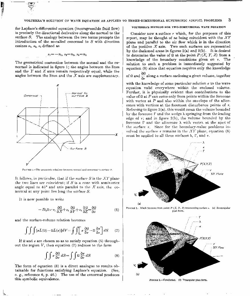
for Laplace’s differential equation (incompressible fluid flow) is precisely the directional derivative along the normal to the surface S. The analogy between tbe two terms prompts the introduction of the so-called conormal to S with direction cosines vl, v2, v3 defined as
VI= -nl, v2=n2, va=na
The geometrical connection between the normal and the co- normal is indicated in figure 1; the angles between the lines and the. Y and Z axes remain respectively equal, while the angles between the lines and the X axis are supplementary.
It follows, in particular, tbat if tbc surface S is the SY plant the two lines are coincident.; if S is a cone with semivert.cx angle equal to 45’ and axis parallel to the X axis, the co- normal at any point lies long the surfa.ce S.
It is now possible to write
and the surface-volume relation becomes
J fJ[uL(Q) --nL(u)ldV= f f[ u g-n gJ&s (7) . .
If Q and u are chosen so as to satisfy equation (5) through- out the region V, then equation (7) reduces to the form
SS aEdS= bV ss c$$dS (8)
The form of equation (8) is a direct analogue to results ob- tainable for functions satisfying Laplace’s equation. (See, e. g., reference 6, p. 46.) The use of the conormd produces this symbolic equivalence.
VOLTERRA’S METHOD FOR TWO-DIMENSIONAL WAVE EQUATION
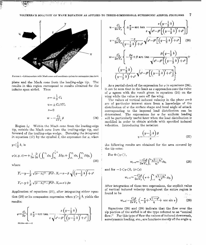
Consider now a surface 7 which, for the purposes of this report, may be thought of as being coincident with the XY plane and parallel to the air flow which is in the direction of the positive X axis. Two such surfaces are represented by the darkened areas in figures 2 (a) and 2 (b) . It is desired to determine the value of fi at the point P:(X, Y, 2) from a knowledge of the boundary conditions given on 7. The solution to such a problem is immediately suggested by equation (8) since that equation requires only the knowledge
an of D and z along a surface enclosing a given volume, together
with the knowledge of some particular solution u to the wave equation valid everywhere within the enclosed volume. Further, it is physically evident that contributions to the value of fi at P can come only from points within the forecone with vertex at P and also within the envelope of the after- cones with vertices at the foremost disturbance points of 7. Referring to figure 2 (a), this would mean the volume bounded by the foreconc r and the wcclge x springing from the leading edge of r; and in figure 2(b), the volume bounded by the foreconc r and the a.fterconc x with vertex at the apex of t.hc surfncc 7. Yinco for tbc bounclary-value problems in- volvecl the surface 7 remains in the XI’ plane, equation (8) must bc applied to all three surfaces X, I’, and 7.
,.._.._ _- h -K --l-
,’
. . ';
FIOURE 2.-Mach forecone from point P (X, Y. Z) intersecting surface r. (n) Rectangular plan form.
(b) -7
FIGURE Z.-Concluded. (b) Triangular plan form.

4 REPORT NO. 889---NATIONAL ADVISOTY COMMITTEE FOR AERONAUTICS
Since there is no way of determining Q and g along r the
attempted solution will be especially difficult unless the particular solution u and its derivative with respect to the conormal vanish everywhere on r. But this is in fact the essential part of Volterra’s method of solution. Thus the proper choice of u is
(This relation, incidentally, is the indefinite integral of the fundamental solution representing a supersonic source in three dimensions [(X-XJ2- (Y- YJ- (Z-Z:1)2]-1/2.) The value of c is equal to zero on the forecone I? since the equa- tion of this cone is
(X-X,)2- (Y-Y,)2- (Z-2,)2=0
and further, since the conormal is always directed along the
forecone, 2 is the gradient of CT along I’ and is also zero.
Equation (8) provides an equality for the distribution of
~2 and z+ over x and T, provided D and n satisfy equation (5)
throughout the enclosed volume mentioned. However, al- though (r satisfies equation (5) everywhere in the enclosed volume opposite T from P (under the XY plane in fig. 2), along the line (Y-YJ*+(Z-ZJ*=O (above the XI’ plane in fig 2) u is infinite and does not satisfy the assumpt.ions made in establishing Green’s theorem. If this line is ex- cluded, however, by means of a cylinder K of radius e, with axis lying along the line (Y-Y,)*+ (Z--Z1)2=0, then equation (8) may be applied to the region outside K and yet within the space bounded by X, 7: and F. In fact equation (8) can then be written
where r1 is the portion of T bounding the region of integration. If R= ,i(Y- Yl)2+ (Z-Z,)z and cylindrical coordinates E, #, and (X-X,) are used, an element of area on the cylinder K is dS= - edJld(X-Xl), while
so that
If this result is applied to equation (9), one gets
and, after differentiating equation (11) with respect to X,
PROCEDURE FOR LIFTING SURFACES AND SYMMETRIC WINGS
When the region considered is that bounded by the surface 7, r, and x’, the portion of X on the opposite side of T from the point P, then u is finite throughout the region and, as a direct consequence of equation (9),
1 a o=-&rx ss ( (13 71+X’ where fi’ is the value of the potential function on the side of 7 opposite P and V’ is in the opposite direction to v on T. Adding equations (12) and (13),
The integrations over T are now in a form which may be interpreted directly in terms of known conditions over bodies with given load or symmetrical section. The integration over X and X’ can be disposrd of by discussing the two cases shown in figure 2. When Q is identified with the velocity potential, its value can be shown to bc zero on X and X’ regardless of whether the leading edge is swept ahead of or behind the Mach cone. When D represents acceleration potential or any of the perturbation velocity components, a discontinuity exists in the value of D for leading edges swept ahead of the Mach cone as in figure 2 (a). Analysis of this case, however, reveals that for all wing problems the inte- gration over X just cancels the integration over X’. When the leading edge is swept behind the Mach cone as in figure 2 (b) the value of Sz is again zero. Thus in any case there results the fundamental equation:
(14)
The counterpart of equation (14) for incompressible fluid flow is well known. (See, e. g., p. 60 reference 6.)
Under the particular conditions for which
aa &a’ -=-7 bV bV (15)

VOLTERRA’S SOLUTION OF WAVE EQUATION AS APPLIED TO THREE-DIMENSIONAL SUPERSONIC AIRFOIL PROBLEMS 5
over the surface 7 equation (14) becomes
(Q-n’) & dS (16)
The restrictions imposed in equation (15) can be given physical significance after the functions Q, W, and the surface r have -been given specific meanings. Consider first the case where 7 is a lifting surface. Obviously the normal induced velocity w is a continuous function across 7. If fi and W are velocity potentials associated with the lifting surface,
and equation (15) is satisfied. If D denotes acceleration po- tential or perturbation velocity U, it is necessary to show that on the lifting surface
au au’ -=-- bV bV’
This relation holds, however, for since w(X, Y, 2) =w’(X, Y, 2) along 7, it follows that
bw bw’ --- ax axi
and from the condition of irrotationality it is possible to ex- press the gradient of w in the X direction as the gradient of u normal to the surface, that is, in the directions of v and v’.
Equation (16) is thus applicable directly to lifting-surface theory in conjunction with either velocity or acceleration potentials. Application can also be made to the determina- tion of pressure distribution over the surface of a symmetric airfoil at zero angle of attack. In this so-called nonlifting case the function 0 is set equal to the induced velocity w, 7 is the plane of symmetry of the airfoil, and equation (16)
can be used to establish the boundary conditions, provided equation (15) is satisfied. For this to be so 3wJbv must equal - bw’lbv’. But conditions of symmetry give w(Z)= - w’( - 2) from which the equality is seen to hold.
RETRANSFORMATION OF COORDINATES
Since
direct substitution into equation (16) yields
Q(X, Y,Z)=
1 b I-S (S-Q’) (x-x,) (Z--Z&LWY,
2?r ax. r, [(Y-Y,)2+(2--2,)2] -&x-xl)2-(y- yJ”-(~--2,)2
This solution applies to equation (5) and, in order to relate problems to the linearized equation (2), it is necessary to use the transformation of equations (3). If the point X,, Y1, 2, transforms to the point ~1, yl, zl, it follows that
Qc?y,4=
1 a
ss
(Q--Q’) (x-xl) (z-q)dqdy1 -- 2r ax 71 ICY-YlY4 (~-~1)21J(~-~1)2-PZ~~Y-Y1)2+ (~-in
where (17)
/?“=M&-1
APPLICATIONS GENERAL REMARKS
Applications in lifting-surface theory may proceed along two possible lines depending upon the boundary conditions specified. In what is usually referred to as the direct problem, or problem of the first kind, the loading is given over the wing and the potential function of the flow field field is calculated. From the potential function the shape of the aerodynamic surface supporting this load can be found relatively easily. The inverse problem, or problem of the second kind, concerns itself with the determination of the loading over a wing surface from a knowledge of the surface shape. In the following sections both of these cases will be considered. The direct problem will be discussed for various plan forms, the analysis proceeding directly from the expression for the potential function given in equation (17). The detailed discussion of the direct problem is justi- fied by its application to the inverse problem where the load- ing over flat plates with rectangular, trapezoidal, and tri- angular plan forms is determined. The mathematics of the inverse problem is less straightforward since the analysis involves the introduction of elemental lifting surfaces with constant loading and the solution of an integrai equation for each plan form.
UNIFORMLY LOADED LIFTING SURFACES JN SUPERSONIC FLOW
Infinite span wing.-Iu order to determine the induced velocities on the surface of an infinite span, uniformly loaded, supersonic lifting surface by means of the methods derived in the preceding section, it is convenient to set Q equal to the acceleration potential cp (reference 2). The lifting surface is, in this case, a surface of discontinuity for the function cp and corresponds to the surface 71 in equation (17). The discontinuity in the value of (o between the upper and lower surface is equal to
where
p, density in the free stream PI static pressure on lower surface p, static pressure on upper surface
It follows that for the uniformly loaded wing in the plane zl=O the discontinuity in the acceleration potential is a constant, say C,. From equation (17)
p(x y +c” 4 ss
(x-xJzdx,d~, 2 t 27r ax t(Y-Y1)2+~21J(~--sl)2-~2~~Y-Yl)2+~21 (1%

REPORT NO. 889-NATIONAL ADVISORY COMMITTEE FOR AERONAUTICS
MO
FIGCRE 3.-Regions of integration for infinite span unswept wing.
A sketch of the airfoil plan form is given in figure 3 and two possible regions of integration are indicated. In all cases the integration with respect to y is performed between the limits at which the radical
vanishes while the integration with respect to x dcpcnds upon the manner in which the forcconc of the point I’ intersrcats the discontinuity surface. Denoting the chord length of the airfoil by c, the following relations are obtained:
cp=O when r~lpz<O
p=&f Co when O=x~/Iz<c
cp=O when c<sFpz
(1%
(When double signs are used, the upper sign refers always to the case where z>O and the lower sign corresponds to z<O.)
The value of the acceleration potential is thus seen to bc zero at all points in space except for those points lying within the region between the wedges extending back from the leading and trailing edges of the airfoil.
It is now possible to determine the induced velocities associated with the acceleration potential just obtained. Since, in linear perturbation theory (rrfercncc 2),
where U, 0, w are respectively the s, y, z components of the perturbation velocities, it follows that
b l 1 r=ay
s _m v; co(x,, Y, z)dx,
w=;J’- :, cp(x1, Y, z)dx,
The induced velocities for the infinite span airfoil result immediately from equations (19) and (21). If the upper sign of a double sign is again referred to the z>O case, the results may be written in the form
1 -1 for 05xTPz<C (22)
Since the vertical induced velocities are constant, it follows that the supersonic airfoil of infinite aspect ratio and uni- form load distribution is a flat plate. The relations between this loading and angle of attack will be considered later.
Lifting surface with rectangular plan forms-The complete discussion of the supersonic lifting surface with uniform loading and rectangular plan form is lengthened considerably by the fact that in calculating the acceleration potential at the point P with coordinates J, y, z it is necessary to distin- guish between several regions in space in which the point may be located. These regions arise from consideration of the manner in which the forecone of the point P cuts the surface of discontinuity. The value of q can be found with approximately equal faci1it.y in each of these regions hut, since this paper is concerned primarily with effects on the surface of the airfoil, the solutions for pertinent regions only will be given here.
Figure 4 shows the rectangular plan form LL’T’T together with the coordinate system to be used. The dimensions of the wing are chosen so that, the Mach cones extending back from the leading edge will not intersect within the boundaries of the wing. This restriction, which is not, necessary but merely simplifirs the analysis, implies that if b is the span of the wing and c the chord length, then
(23)
is the so-called 14ach angle of the
stream and equal to the scmivrrles angles of the Mach cones. The loading over thr> rrct angular plan form is to be uniform
so the expression p,&-(pL is set equal to (TO for -; bi& b
and O&&C. Thr accrlcration potential, cxprcsscd as a function of x, y, Z, is thus obtainable from equation (17) and the limits of integration must be determined from the position of P. From reasons of symmetry, only the portion of space for which y>O need be considered. Once the acceleration potential has been calculated, equations (21) may be used to calculate induced velocities. The results of such calcula- tions are given and the same convention for double signs is used.
Region I,: Behind the leading-edge wedge, ahead of the trailing-edge wedge, and bounded laterally by the y=O
VOLTERRA’S SOLUTION OF WAVE EQUATION AS APPLIED TO THREE-DIMENSIONAL SUPERSONIC AIRFOIL PROBLEMS 7
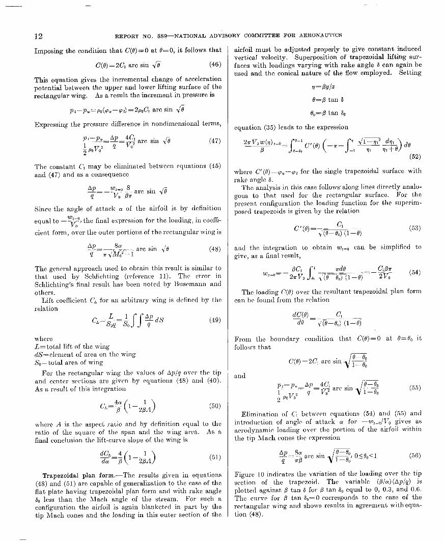
F~cnm 4.-Lifting surface with Mach cones and coordinate system for rectangular f&m form
plane and the Mach cone from the leading-edge tip. The results in this region correspond to results obtained for the infinite span airfoil. Thus
.=&If C O
Region IZ: Within the Mach cone from the leading-edge tip, outside the Mach cone from the trailing-edge tip, and forward of the trailing-edge wedge. Denoting the integrand in equation (17) by the symbol 1, the expression for ‘p, when
y<i b, is
cp(x,y, z,=+& ;p, (~~y~dxlJ:~b Idyl+J~dx,J~Idyl)
(25) where
Y1=y-$ 1/(x-x1)2--p% x1=x--p &-f b)2+z2
y,=y+j J(J:-x1)2-p% X2=xrfPz
Application of equations (21), after integrating either equa-
tion (25) or its companion expression when 1~>$ b, yields the
results:
$+; *;-arc tan x (Y-; b)
-[(y-f b)‘+z2]
CO u=2?rvo *g-arc tan
x(x+) ,\
z ox’+ [(y-i by++
‘=2%(&y+z, +-2+‘[(y-; by+zz] (26)
co W=wo ,(,-; b) -‘+’ arc tan ,,z [(y-$ b).+,$!,+
(‘;’ 1> (y-z 6) +z2
,/i-a’ [(y-; by+$]]
As a partial check of the expression for cp in equations (26), it can be seen that in the limit as z approaches zero the value of cp agrees with the result given in equation (24) on the wing while the value is zero off the wing.
The values of vertical induced velocity in the plane z=O are of particular interest since from a knowledge of the distribution of w the surface shape and local angle of attack corresponding to the imposed load distribution can be determined. The expressions for w for uniform loading will be particularly useful later when the load distribution is modified in order to obtain airfoils with specified induced velocities. Introducing the notation
(27)
the following results are obtained for the area covered by the tip cone:
For O<q<l, __-
--COP .J1--T12dq1 __- - wz=o= 2uv, 1 S 1112 (28)
and for -l<o<O, (x<c)
- COP wz=o= 2rJ7, ?r+ ( s rl JF;;;’ -19,2 dv, > After integration of these two expressions, the explicit value of vertical induced velocity throughout the entire region is found to be 2- ,I
COP wz=o=2?rvo ?r+Ji=? ---% q + arc sin 7 (29)
Equations (28) and (29) indicate that the flow over the tip portion of the airfoil is of the type referred to as “conical flow.” For this type of flow the values of induced downwash, aerodynamic loading, etc., are functions merely of the angle q.
83118441t-2

8 REPORT NO. 889--NATIONAL ADVISORY COMMITTEE FOR AERONAUTICS
Busemann (reference 7)) Stewart (reference S), and Lager- Strom (reference 9) have developed analyses for certain plan forms which are postulated on the existence of this type of solution. In all cases for which the flow field is conical the problem is effectively two-dimensional. Such a simplifica- tion reduces the analysis in this report to a consideration of a single integral equation while in the references just men- tioned complex variable theory can be applied directly.
Tip of swept-forward lifting surface.-Consider the tip of a swept-forward supersonic lifting surface with uniform loading (fig. 5)) the angle 6. between the leading edge and the x axis and the angle a1 between the trailing edge and the x axis both being less than the free-stream iMach angle I*.
FIGURE 5.-Tip of swept forward lifting surface with traces of Mach CO~PR, cwrdinatr systrm, and rrgions definrd for equations (.32) and (.%I.
In carrying out the integrations it is nrcessary to distinguish between the type in which the tip boundaries are behind the Mach cones and the type in which the tip boundaries are ahead. The analyses of these two cases are of equivalent complexity, however, and can be handled with equal facility by the methods outlined. For all surfaces whose leading edges form an apex, only the case where the wing bounclaries are behind the Mach cone will be considered. A Cartesian coordinate system is chosen as shown so that the origin
lies at the apex, the positive x axis extending downstream, the y axis extending laterally, and the z axis being directed normal to the plane of the plan form and to the free-stream direction. The equations of the sides of the lifting surface are
y=o
y= -x tan so= -!! x P
and
y=-(x-c) tan S,=--$ (x-c)
The calculation of (o(z) y, z) again must be divided into cases depending upon the location of the point P: (x, y, z). In the results listed below arc included the explicit expressions for cp (T, y, z); the induced velocities, however, are given only in the plane z=O, as the integration to obtain a general expression is difficult. The velocities in the z=O plane, which are sufficient for the purpose of this investigation, can be obtained from a simpler integration since. for the integral involved,
lim z-0 I(x,y,z)dr= S S l(r,y,O)ds
This simplification was used in the analysis of most of the lifting surfaces investigated. As before, it is assumed that the discontinuity in p is equal to Co. hioreover, the es- pressions for wzEo are given in terms of the variables 11 and w where
PY 11=- 2 and w=l -4 (30)
In this manner the solution is shown to bc conical in the rcxgion ahcatl of tht trailing-tip 11~11 cone (fig. 5). For points behind this ,1Iach conr the Aow is not conical but a function of both 11 and W.
Region J1: Inside the Irading-tip 1lach cone and ahead of t hc trailing-tip h\lach cone. Integration of equation (17) yields the result
co I xy+x2 tln-pz2eo
p=FiL -arctan --. 22
zI.‘i2-/?2(y2+zq +arc tan- ..__P-
%2’X2- p2(y2+ 2) J
and, after further calculation, (31)

VOLTERRA’S SOLUTION OF WAVE EQUATION AS APPLIED ‘I’0 THREE-DIMENSIONAL SUPERSONIC AlRFOIL PROBLEMS 9
Region I?: Inside bot,h tip Mach cones. The solution in this region is simplified through use of the fact that for linear differential equations any algebraic sum of solutions will be another solution of the equation. Since the differential equation for the acceleration potential is linear, this property can be applied to obtain a solution for the region I2 by sub- tracting from the expressions given for region Ii correspond- ing expressions in which t,he variable & replaces & and (X-C) replaces 5. Thus
q=c” [
-arc tan XY xy+x2 $--8z2eo
2lr 2. Jx” - p2 ( y2 + 2) +arc tan - -+
21/x2--p2(y2+z2j
e (x-c)y+(x-c)“+&3,
arc tan (x--c)Y P 21/(x-c)2-p2(y2+22) -arC tan z,/(2-c)Lpyy2+22) 1
and for -l<q<l (33)
W COP Jl-q” 1 Zc”=27rv; q [-
--e 0 arc cash ji-i+
Jr’ eo2 (I+ eoq) e.
~--. arc cash I-~o+~),-- -; tiJmTj2 + i
e1 arc cash Ifi-
-Ji - e,2 -- arc cash p/y-j 6
(34)
Lifting surface with trapezoidal plan form.-The linear property of the differential equation may bc used to advan- tage in determining the flow about a trapezoidal lifting sur- face with uniform lift distribution, since the boundary conditions within the plan form of the airfoil arc obviously satisfied when the acceleration potential for a triangular tip is subtracted from tlic poteutial for tlic rcctangulai surface.
Supposc (fig. 6) the nnglc of rakr of the trapczoitl is 6. and that a0 is less than the Mach angle p. Thr acceleration potential will bc identical, over the central portion of the surface, to that for the lifting surface of infinite aspect ratio. Over the parts of the surface which arc blanketed by the tip Mach cones the flow will, howcvcr, be modified. Because of symmetry the determination of this modification need only be carried out on one side of thr figure.
If the coordinate axes arc chosen as shown in figure 6, the lateral boundary of thr lifting surface is
y= -x tall &“= -!@ P
It has been shown that both the rectangular plan form and the triangular plan form experience conical-type flow over the region within the tip Mach cones. Thus, the variable 77 clefined in equation (30) may bc used.
Region II: Inside the Mach cone originating at the leading- edge tip, outside the Mach cone from the trailing-edge tip, forward of the trailing-edge wedge, and to the left of the y=O plane.
For - l<q<O:
COP =2?rv,
-- ;+ --- arc tan dlyr12 +$ arc cash .ii -
Ji=@ e. arc cash #$$#I (35)
FI(:~K& Ii.-Trniweoidal lifting surlncr with traces of Mach cones, coordinate system, and regions deAned for equation (35).
Swept-back lifting surface.-As another example of the way in which the linearity of the differential equation may be ut,ilizetl to obtain further solutions, the induced vertical velocities for a swept-back wing will be determined for the cast in which the leading and trailing edges lie behind their rcspcctivc ;\ Iach cones (fig. 7). The boundaries of the plan form arc given by the equations
4 y=-p (x-c), Y=$ (J-C)
The flow will be conical ahead of the trailing-edge Mach COIN where the induced velocities can be expressed in terms of the variable 7. Behind the trailing-edge Mach cone the flow will not be conical but will bc expressible in terms of the variables 7 and w= 1-c.
X
Consider first the region of conical flow. In order to determine wZZo for a given value of 1 it is possible to con- sider separately the induced effects produced by each half of the surface. But in the region ahead of the trailing-edge Mach cone, the induced velocities arising from one half of the surface are given by the formula for a similar region on the swept-forward surface. For reasons of symmetry the results for thr entire swept-back lifting surface need only be given for values of 7 within the limits - l<v<O.
.-

11111~11111l11l1l llllllllllll
10 REPORT NO. 889--NATIONAL ADVISORY COMMITTEE FOR AERONAUTICS
I MO
i
Leading-edge Mach cone -,.
FIGURE 7.-Swept-back lifting surface with traces of Mach cones, coordinate system, and regions defined for equations (36) and (37).
In the region where the flow is not conical the solution will be built up of a combination of solutions obtained from the regions of conical flow.
Region I1 : Inside the leading-edge Mach cone, outside the trailing-edge Mach cone, and to the left of the y=O plane. For -l<r]<O
arc cash L+----- 41 -eo2 1171 00 arc cash (wq 0 v2 1
-Region Iz: Inside both Mach cones and to the left of the y= 0 plane. The solution in this region can be produced by subtracting from the value of wZCo given for region 1, the value of wZno g iven for the same region except that in the latter case &, is replaced by 61 and z by (x-c). Thus,
Although the uniformly loaded lifting surface was the only prescribed loading analyzed, it should be noted that the basic integration leading to a solution of this type of prob- lem (equation (17)) is in no way restricted to a uniform load. Arbitrary loadings that may or may not be analytic functions of x and y can be specified and the problem therefore becomes
one of technique in integration. The solutions for the uni- formly loaded surfaces, however, are particularly useful. By methods of superposition these solutions can be used to ob- tain the surface loading for specified plan forms (the inverse problem) as will be illustrated in the following section.
LOAD DISTRIBUTIONS ON FLAT-PLATE LIFTING SURFACES IN SUPERSONIC FLOW
Infinite span wing.-Since the vertical induced velocity is constant for the supersonic airfoil of infinite aspect ratio (equation (22)) and uniform load, it follows that the airfoil is a flat plate. This property distinguishes the infinite aspect ratio problem from all other plan forms considered, for the load distribution must be modified in the latter cases so that twist and camber are removed from the wing to obtain a flat plate.
Denoting the angle of attack of the airfoil by CL,
we0 (y=-- --=a2 dM= vo (38)
Moreover,
and, setting P1--Pu=Po((Pu-(Pl) ‘POQO
P~--P~-AP ____- 1 v2 P KPO 0
it follows that
(39
Eliminating Co between equations (38) and (39),
Ap 4a --=- -- P ,lMo’-1 (49)
The result given in equation (40) is the well-known Ackeret expression developed in reference 10. The derivation here follows the approach of Prandtl (reference 2).
Rectangular plan form.-Since the vertical induced velocity for the uniformly loaded supersonic airfoil of rectangular plan form is not constant over the portion of the wing covered by the tip biach cones, it is necessary to modify the load distribution within this region in order to get a flat plate. The determination of the required load distribution will be shown to depend on the solution of an integral equation and subsequent problems dealing with other plan forms will, from a mathematical st.andpoint, be similar in form.
The rectangular plan form will be thought of as being built of superimposed trapezoidal lifting surfaces with variable angles of rake (fig. 8), each t)rapezoidal surface having a. uni- form load distribution but. with loading allowed to vary with the variable rake angle 6.
Since the flow over the part of the airfoil within the Mach cone is conical, it. is possible to express wZEo as a function of q where
+! X
Setting p t.an 6=8

-.. h- )- pgy---
VOLTERRA’S SOLUTION OF WAVE EQUATION AS APPLIED TO THREE-DIMENSIONAL SUPERSONIC AIRFOIL PRORLICMS 11
and using equation (35)
where C’(0)=cpu-(ot for the single trapezoidal surface with rake angle 6.
The solution of the problem depends on the determination of a function C’ (0) which, when substituted in equation (41), will yield a constant value of w,=,(~); that is, a value of w,=~ independent of the variable 7. Imposing the condition that
dWZ=ll-o dv
the problem is resolved into one of solving the equation
By means of the notation
the integral equation is written in t,he form
where the singularity in the integrand necessitates the USC of the infinitesimal E. The evaluation of the derivative thus leads to the expression
e
FIQURE Q.-Region of intogrntion showing line of singularity for equation (44).
It can be shown from equation (35) that, if C’(O) is a con- tinuous function,
Hence o= JGZ 1 CYe)de
71 S o fl+e (42)
and the solution of this equation is
c’ (6 = aej- (43)
where C, is a constant to be determined later. Substituting from equation (43) into equation (41)
(44)
The region of integration in the v1O plane for the double integral of equation (44) is shown as the cross-hatched area of figure 9, a singularity in the integrand occurring along the lint e= -111. Rewriting the equation and reversing the order of integration in the double integral,
~z?rvowbf~z=o~ P4
- - 2~ arc sin@ ];-ljzJ”l F d7,
-q-c de h+e 483 1
The bracketed expression in this equation can be shown to vanish for all values of Q between zero and -1 so that, finally,
wzzo=~ 27r arc sin 43 1 1 - ClPT =p 2vo (45)
0
Since the trapezoidal lifting surfaces are superimposed, the loading C(O) over the resultant rectangular plan form satisfies the relation
13. .- ___. -_ - . . . . . I . , . I , - . - - . . _ .
- -
12 REPORT NO. 889-NATIONAL ADVISORY COMMITTEE FOR AERONAUTICS
Imposing the condition that C(S)=0 at 0=0, it follows that
C(e) = 2C, arc sin fi (46)
This equation gives the incremental change of acceleration potential between the upper and lower lifting surface of the rectangular wing. As a result the increment in pressure is
pl-pu=p,(cp,--cpl)=2poC~ arc sin JB
Expressing the pressure difference in nondimensional terms,
P~P,-AP-~C, 1 4 VO”
arc sin Je 2 PoVo2
(47)
The constant Cl may be eliminated between equations (45) and (47) and as a consequence
AP WZ4 8 -=-- ~- P VII Pa
arc sin JS
Since the angle of attack O( of the airfoil is by definition
equal to w’~f, the final expression for the loading, in coeffi- --v 0 cient form, over the outer portions of the rectangular wing is
AP 8a (1
.=. arc sin T’e T>‘M)*- 1
The general approach used to obtain this result is similar to that used by Schlichting (reference 11). The error in Schlichting’s final result has been noted by Busemann and others.
Lift coefficient CL for an arbitrary wing is dcfinccl by the relation
(49)
where L= total lift of the wing dS=element of area on the wing So= total area of wing
For the rectangular wing the values of Ap/a over the tip and center sections arc given by equations (48) and (40). As a result of this integration
where A is the aspect ratio and by definition equal to the ratio of the square of the span and the wing arca. As a final conclusion the lift-curve slope of the wing is
(51)
Trapezoidal plan form.-The results given in equations (48) and (51) are capable of generalization to the case of the flat plate having trapezoidal plan form and with rake angle & less than the Alach angle of the stream. For such a configuration the airfoil is again blanketed in part by the tip Mach cones and the loading in this outer section of the
airfoil must be adjusted properly to give constant induced vertical velocity. Superposition of trapezoidal lifting sur- faces with loadings varying with rake angle 6 can again be used and the conical nature of the flow employed. Setting
rl= OYlX
e=p tan 6
e,=p tan ?io
equation (35) leads to the expression
(52)
where cI(e)=pu-‘pl for the single trapezoidal surface with rake angle 6.
The analysis in this case follows along lines directly analo- gous to that used for the rectangular surface. For the present configuration the loading function for the superim- posed trapezoids is given by the relation
and the integration to obtain wZcO can be simplified to give, as a final result,
PC1 l S Tde _-- -~ wz=n=-2~~~ ea I’(epYI&j (1-e)
_ Cl@ 2Vo (54)
The loading P(0) over the resultant trapezoidal plan form can be found from the relation
From the boundary condition that C(e)=0 at e=eo it follows that
c(e) =2C, n.rc sin e--e0 21-- i-e0
nncl P~-P,,-AP 4c, - ; Po1/;12
P = v7 arc sin
.- (55)
Elimination of CL bctwcen equations (54) and (55) and introduction of angle of attack LY for -w,=,/Vo gives as aerodynamic loaclin, v over the portion of the airfoil within the tip Mach cones the expression
(56)
Figure 10 indicates the variation of the loading over the tip section of the trapezoid. The variable @/a)(Ap/p) is plotted against P tan 6 for P tan a0 equal to 0, 0.3, and 0.6. The curve for p tan &=O corresponds to the case of the rectangular wing and shows results in agreement withequa- tion (48).

I” x-v+- ,.. -. -, I-.-I -6 ,. , .i
VOLTERRA’S SOLUTION OF WAVE EQUATION AS APPLIED TO THREE-DIMENSIONAL SUPERSONIC AIRFOIL PROBLEMS 13
By means of equation (49) togct.hcr with equations (56) and (40) the lift cocfficicnt of the tmpczoitlal wing is cxprcs- sihlc in the form
CL=“;; ( 1 -!“b tall 50-,$ tan ,u
1-i tan 60 1
(57)
Introducing the aspect ratio A of the wing where
&/&--.Jm c 1-d tan 60
( >
one gets for lift coefficient the relation
(5%
From equation (57),
--=--- (
c c dC, 4 l--z6 tan 6o-26 tan p
da P l--i tan 60 (5%
In figure 1 1, p ‘2 is plotted as a function of Ap for &=O, it
and 1. The curve for Bo=O agrees with results given by equation (51) for the rectangular wing. All curves are
0 2 4 6 8 IO
tcrminatctl at values of AID for which thr Lip AIach cones intrrscct on the trailing edge of the wing.
Triangular plan form, type l.-The pressure distribution over triangular lifting surfaces with constant induced vertical velocities will bc devcloprd in the following three sections. These plan forms arc indicated in figures 12(a), 12(b), and 12(c) and shall bc denoted, respectively, as types 1, 2, and 3. Types 1 and 2 are actually special casts of type 3; namely, the cases where one leading rdgc is parallel to the free stream, and where both leading edges make equal angles with the stream direction. Type 3 includes any plan form which has leading edges swept behind the Mach cone but on opposite sides of an axis drawn through the vertex of the triangle and parallel t,o the free stream; and, further, has a trailing edge such that the Mach cones from either tip do not cross the surface of the wing. The principal reason for considering the three types separately is to show the manner in which the spanwise loading appears in the solution of t,he problem. In types 1 and 2 the proper load distribution is found readily while the final type requires a more careful treatment.
In order to determine the load distribution over the airfoil it will be convenient to use a differential element over which the loading is uniform. The elements may then be summed and the distribution of loading adjusted so that the induced vertical velocity at any point on the total lifting surface is
8. -

14 REPORT NO. 889-NATIONAL ADVISORY COMMITTEE FOR AERONAUTICS
klo 1
*Y
8’ ,’
,’ \ I’ ‘\
‘\ #’
1 X
PI
Ilr, I
WY
#’ I’
.’ /’
a’ #’
6’ #’
\
FIGURE la.-Triangular flat platr lifting surfaces. (a) Type 1. (b) Type 2. (cl Type 3.
constant. For the triangular plan forms it is possible to assume that conical flow exists and the analysis may be carried out using the angular coordinates that have already been introduced.
If the elements are summed over the type 1 triangular wing, induced vertical velocity is
Figure 13 shows the elemental lifting surface to be used. The sides of the element extend back from the tip of the Mach cone; making angles 6 and S+ A6 with the positive x axis or free-stream direction. Corresponding to previous notation, the relations 0=fl tan 6 and e-j-Ae=/3 tan (h/-As) are used. The vertical velocity induced by the element of surface may be denoted by Aw and it follows that
(63)
where c(e)=p,-pol for the element at 6=arc tan - ;. If
wzEo is constant, then
Aw=w(e+Ae, 9) -w(e, 1) and from this criterion the function C(0) will be determined.
where w(e, 7) and w(0+ A0,v) arc the velocities induced by the triangular-tip surfaces with uniform loading and with tip angles equal to 6 and s+As, respectively. Applying a limiting process,
lim gxlim w(e+ae, d-w(e, l?)=* A0+0 A0 A9+0 ae be 030)
It follows that wLsO for the resultant lifting surface will be evaluated by an integration with respect to 0. If bw,,olbe can be expressed in the form of an integral with respect to 7, t.he relation for wzzo will then be similar to those given in equations (41) and (52) for the previous plan forms and the expectation will be that the function C(0) can he deter- mined to give constant induced vertical velocity.
The method of attack just outlined is postulated on the existence of an integral expression for aw,=,/dB. Such a,n expression is, however, obtainable directly from the integrals in equat,ion (32). Integrating these relations by parts after first differentiating by 0, leads one to the formulas:
For -l<q<O
bW,=O -=2$o[g&+J be
and for 0 <V < 1

VOLTERRA’S SOLUTION OF WAVE EQUATION AS APPLIED TO THREE-DIMENSIONAL SUPERSONIC AIRFOIL PliOBLEMS 15
Thus, using methods similar to those introduced in the development of equation (42),
(+g Jl-12 1 *o C(e)de __ __ aa 8 s
f%l a@ de+- 0 v-i-e 7%--172 o 17+e s
=a- S 00 C(e)de .-a~ o q+e (64)
The general solution of this equation is
where Cl and 6, are constants. Since, however, the Kutta- Joukowski condition requires that loading vanish along the edge 0=0, it follows that C,=O and the required loading takes the form
(65)
If equation (65) is substituted into equation (63), vertical induced velocity can bc calculated from the cspression
(66)
The region of integration in the ~1, 0 plane for the double integral of equation (66) is shown in figure 14 for the case in which -&<q<O. A singularity in the integrand of the double integral exists along the line O+ql=O. Reversing the order of integration, equation (66) may bc rewritten as
27rvow,=o ea de -au pc, =-I
/yimq2 I’ _ _ .~_ _ --.- - (e+d &Yeo-e) S - -c!!.
0 -1 qldl--1112
S 00 de *‘) dq, S eo de 0 (e+d &Ye,- f9 --Ba q1 Jiq 0 (e+d4@Ff3
(67)
The single integral in equation (67) has a singularity at 0= -1) since -O,<q<O and 9 therefore lies inside the region
e
FIGURE l?.-Region of integration showing line of singularity for equations (66) and (78).
of integration. A corresponding singularity occurs in the second of the double integrals at e=-ql. Consider, there- fore, the integral
S e0 de =lim 17s
-q--c 0 (e-tq) @@F@ c+~ 0
‘90 J
de 1 -?fc (e+q) -&&F8j (68)
The indefinite integral is
1 J-qeo--112
ln -qeo+eeo+2qe-2~(-qeo-q2)e(eo-e) e+q
so that the definite integral is
The value of this expression is 0 ant1 equation (67) therefore bccomcs
2aVowz,o pc, =- J
‘-ea 80 de -L ..-. .z (69) -, .(e+q,) ~e69,-e)
Since, in this region of integration, -l<q<-0, it follows that
S ec de 0 (e+d liw-44)
1 --17,eo+-eeo+2~1~ 00 1 --ii- l.~qleos-d arc2 ‘all~~i(~~~+q,eo)e(eo-e) o =x(x+l7, and
The integral of equation (70) can be transformed by means of purely algebraic substitutions into a form that integrates immediately into complete elliptic integrals of the first and second kind. However, in the consideration of the type 3 plan form it will be necessary to resort to other methods of transformation, so that a more uniform approach, employing Jacobian elliptic functions, will be used throughout. (See reference 12.)
The quartic under t.he radical in equation (70) is first re- duced to an expression of the type appearing in elliptic in- tegrals of canonical form. This is accomplished by succes- sive application of the transformations
k+ls ql=--- and s=:
where k and 1 are chosen so as to destroy the odd powers of the variable. By means of these transformations, induced velocity becomes

16 REPORT NO. 88W-NATIONAL ADVISORY COMMITTEE FOR AERONAUTICS
PC1 (1-k2)k2 S ;
___- wz=o=m z(Bo-k) (1 -k2)
[t2+(k-i) t-l]dt (71)
1 (1 -k2t2) J(1 -t”) (k2tL 1,
where k=l- l/F@
e.
The integration of equation (71) will be performed after first considering two parts such that w~=~=w~~w~ where
PC, (1-k2)k2 i wl=~o Ti.(o,,-k) (l-k? s 1 (l-kk2t2)1/(l--t2)(k2t2-1)
and
w2= -PC, (1 -P)dt ____ __ 2vo dk(o,-k)(l-k2) (1 -k*P) v’n?F)pt2- 1)
This separation is prompted by the fact that the integral for w1 is expressibIe in terms of eIementary functions after the simple transformation t*= z. The results of such an integra- tion lead to a value that is zero at the lower limit and infinite at the upper limit. However, an inspection of the original integral in equation (70) shows that wZZo is finite so the infinity obtained for w, must be canceled by a corresponding infinity of equal magnitude in w2. The actual proof of this statement necessitates, of course, treating the combined expressions as an indeterminate form where the upper Iimits
of the integrals for w1 and w2 are replaced by i+ e and the
limit is taken as E approaches zero. Introduce now in the integration of w2 Jacobian elliptic
functions and set
so that t=sn(u, k) =snu
dt=cnu dnu du
The expression for w2 becomes
PC1 (l-kkz)k2i I’ K+ie’ ‘)
w2’m dk(e,-k)(i-kz) K E du
where K and K’ are the complete elliptic integrals of the first kind with respective moduli k and k’= l/l -k2. Intc- grating and combining with wl, one has
PC, (l-kk2)k2i _-. 2Vo &(e,-k)(l-k2y
where E(u) is the incomplete elliptic integral of the second kind. After substitution of the limits, induced vertical velocity is
PC1 (I-k2)E’ wp=o=-21/To J@jo-k) (l-k*) (72)
where E’ is the complete elliptic integral of the second kind with modulus k’= Jl - k2. Equation (72) can be further simplified by writing k in terms of B. so that
PC1 wz=o= -2vo J
al+ J1-eo2) E, eo2 (73)
where the modulus of E’ is 41-k~ and k= i- Ji-eo2 B
P
For the loading in question
and
PI-PU=PO('P,r-'93=poC~ e J so--e
pF Tj PoVo2
By means of equation (73) the constant C, may be eliminated and
Ap 2a /2e(i-Ji-eo2) P PE’T eo--8
I 6
.I I I I I ‘7” ’
I _ L
0 .2 .4 .6 .8 I.0 P fan 6
FIGURE X-Load distribution over triangular plan forms of type 1.
(74)
VOLTERRA’S SOLUTION OF WAVE EQUATION AS APPLIED TO THREE-DIMENSIONAL SUPERSONIC AIRFOIL PROBLEMS 17
Figure 15 shows the variation of E ? with P tan 6 for values
of p tan & equal to 0.3, 0.6, and 0.9. From equations (74) and (49) the lift coefficient of the right
triangle wing with trailing edge normal to the free-stream direction can be determined. It follows that
or, since C(e) = C(- e) ,
.: G’~~2(l-Jl-s,z) (75)
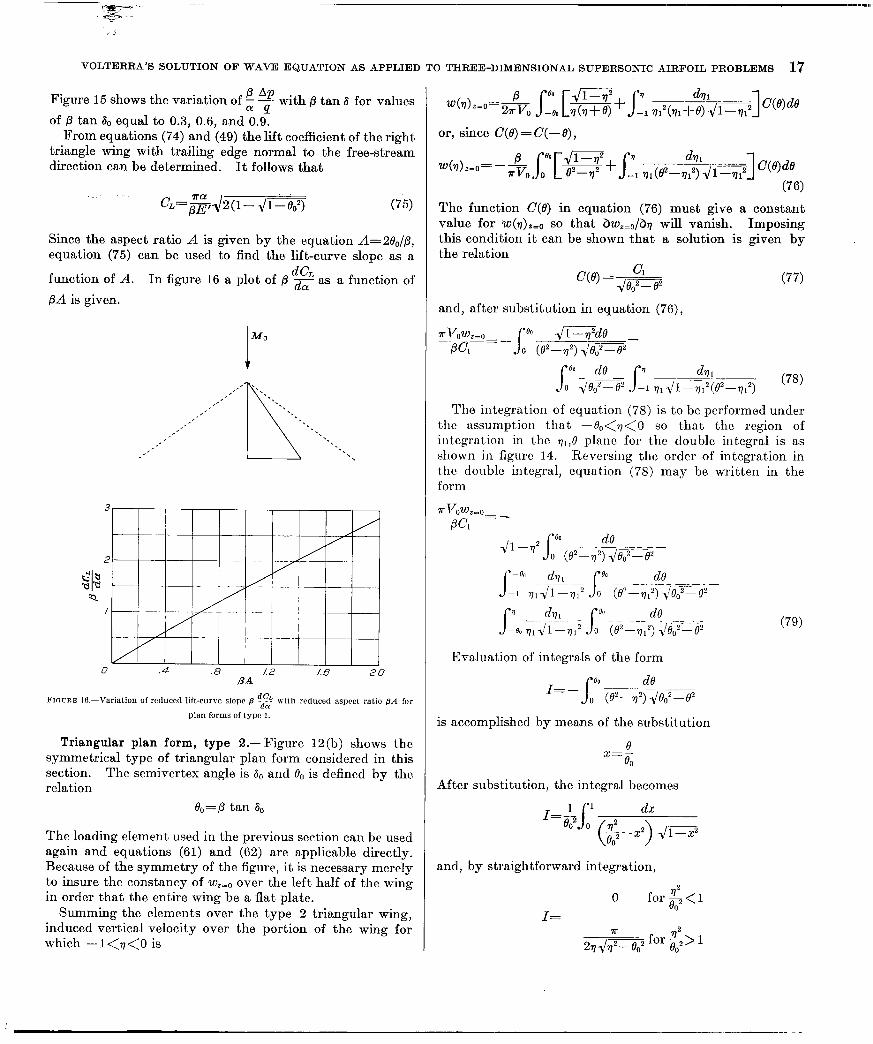
Since the aspect ratio A is given by the equation A=ae,/p, equation (75) can be used to find the lift-curve slope as a
function of A. In figure 16 a plot of /3 ‘2 as a function of
@A is given.
MO
t
,e’ ‘. ,’ ‘\ ,’ -.
,’ -. I’ . .
,’ . . ,’
L
. . ,’ *. ,’ -. I ‘. ,*’ -. ,’ ‘. ‘.
.4 .8 L2 2.0 R-4
F~nrm It!-Variation of reduced lift-curve slope B cd2 with reduced aspect ratio p.4 101
plan forms Of type 1.
Triangular plan form, type 2.-Figure 12(b) shows the symmetrical type of triangular plan form considered in this section. The semivertex angle is & and B0 is defined by the relation
e, = p tan A0
The loading element used in the previous section can be used again and equations (61) and (62) are applicable directly. Because of the symmetry of the figure, it is necessary merely to insure the constancy of wzso over the left half of the wing in order that the entire wing be a flat plate.
Summing the elements over the type 2 triangular wing, induced vertical velocity over the portion of the wing for which - 1 <‘I <0 is
The function C(0) in equation (76) must give a constant value for ~(7)~~~ so that dw,,,/brl will vanish. Imposing this condition it ca.n be shown that a solution is given by the relation
(77)
and, after substitution in equation (76),
?rvow,=o J’ eo --
-,iC?de -p4-
_ 0 (e2-g) Jeo2-e*
a0 de r ~~-:
7 dm - c 0 Jeo2-e2 s -I v1 J1-T(e2-q12) (78)
The integration of equation (78) is to be performed under the assumption that -e,<~<O so that the region of integration in the 91,e plane for the double integral is as shown in figure 14. Reversing the order of integration in t.hc double integral, equation (78) may be written in the form
TVoW,=o PC1
Evaluation of integrals of the form
I=- ea S de o (e+q) Jeo2-82
is accomplished by means of the substitution
s=!- e. After substitution, the integral becomes
and, by straightforward integration,
0 for $j<l I=
77 2
211J$-eo2 for $> l

18 REPORT NO. 889-NATIONAL ADVISORY COMMITTEE FOR AERONAUTICS
This result shows that the second double integral of equation (79) vanishes (since f&2>v12) as does also the single integral in the equation. For the remaining double integral, however, e,2<q12 and
equation (71) transforms to
1 PC, x S z2dz
wz=“=-zv, 1 J(z’-l)(l-T?j
Introducing the modulus k=& and making the substitution
z=sn(u, k) =snu
one gets the expression
$Cl S IC+iK’ %=o=q K sn2udu
BG E’ =--- 2Vok2
where the prime again refers to the complementary modulus .~ k’= Jl-k2 of the complete elliptic integral. Since k = B.
PG E’ wz=o= - 2vo~02
where k’ = 1/l - eo2
(81)
For the loading in question
PC--P, AP 2G =-= 1 2 PoVo2
(1 Voz ,leP
so that, eliminat,ing C, between this equat,ion and equation (81).
AP 4aeo2 Q=pJp=$ E’ (82)
Figure 17 shows the variation of $ F with P tan 6 for values
of /3 tan so equal to 0.3, 0.6, and 0.9. From equations (82) and (49) it is possible to find the
expression for lift coefficient of a triangular or delta wing. Thus:
(y =2Aar = PE’ (83j
Since aspect ratio of the wing is
*2!-0 P
lift coefficient becomes
FIGURE li.-Load distribution over triangular plan forms of type 2.
where the modulus of E’ is k’= J l- htP This result 16 ’ agrees with tha.t obtained in another manner by Stewart,
(reference S). In figure 18 a plot is given of p $2 as a
function of pii. Triangular plan form, type 3.-Figure 12 (c) shows the
plan form now to be considered. Relative to the J: axis or free-stream direction the sides of the triangle form the angles 6. and 61 so that the total vertex angle is 60+61==2A. The variables B. and e1 are also introduced satisfying the relations e,=p tan 6,, e,=p tan 6,. The same loading element that was used for type 1 and type 2 triangles may be used and equations (61) and (62) apply. It will then be necessary to determine the distribution of load so that the induced vertical velocity over the plan form is a constant. Since this induced velocity must be the same on both sides of the 6=0 axis. two equations result:
For -l<q<O

VOLTERRA’S SOLUTION OF WAVE EQUATION AS APPLIED TO THREE-DIMENSIONAL SUPERSONIC AIRFOIL PROBLEMS 19
I MO
.* ‘. I’ L’ *. -. .- *. .’ ,’ *.
.. A
.’ *. .’ *.
,’ -. -’ ‘.
I’ ‘I I’ ‘.
.’ ‘. . *-.
4
/ 3 I ,I I I I I/ I I I
I
.I % & I 9
0 .8 I.6 2.4 3.2 AA
d CL
and for O<q<l
S/l for
From the solutions to the problems of type 1 and type 2 it is possible to construct a solution of the more general problem by expressing the loading function in the form
(87)
where A and B are constants that can be detcrmincd in terms of wzEo from equations (85) and (86). Equation (87), in conjunction with equations (85) md (86), yields the oxpres- sions
where
The evaluation of Z&(0,, 0,) and H,(O,, 0,) is accomplished in the same mamer as has been used previously: first, a reduction of the quartic under the radical to canonical form and second, transformation by means of Jacobian elliptic functions followed by direct integration. Since the cacu- lations for both equations are quite similar, only in the case of H,(O,, e,) will the details be mentioned.
By means of the transformations ~l,~~:: and a=:, where
a= i-e,e,-J(i-eo2j(i-e,2)
eo+el
The introduction of the symbols R and k defined as
equation (89) reduces to
1 Hl=a2Rk I--- S [P+t(a-b)-l]dt
1 (1 - a’P) Jct’-lFkFj
(91)
(92)
(93)
(94)
(95)
The integrand clivides naturally into two parts, one containing even powers ant1 one containing odd powers of t in the nu- merator. The lat terpart integrates into elementary functions nftcr substituting t=u2 and equation (9.5) thereby becomes
Setting
1
s
5 12=
(t’- I)dt 1 (1-u2t2) J(t’-1) (l-k2t2)
and substituting
one gets x=sn(u, k) =snu
ri+irc 12=i
s [ l+(a’-1) 13;n2u du
K 1 If sn y=i, I2 now may be written as
or
I,--K’--i dny s
K+iK’ k2snycny K
k~ewyn$dw;;2u &
I,=-K’-i J
where TI(u,y) is the fundamental elliptic integral of the third kind.
lb: . __.. - , , . . , , . . , , . , . ,m.--mm-.

20 REPORT NO. 88+-NATIONAL ADVISORY COMMITTEE FOR AERONAUTICS
The evaluation of II(U, Ic) is best achieved by means of its expression in terms of theta functions and zeta functions. Thus
fl(% Y) =; 1% e(uSr) e(“-r) +uz(y>
and the bracketed term in equation (88) is
1 e(K+iK’-4e(K+r) IT(K+iK’,y)--nK,y)=Zlog B(&-r)B(K+iK’+rJ+
iK’Z(r)
The theta functions are quasi-periodic, that is, they satisfy the relations
e(U+2K)=e(u)
0(u+2iK’)=-e g (I.?-iu)
8 (u)
From this property, together with the fact that e(u) is an even function, it follows that
Moreover, since
there results
~(K+iK’,r)--nK,Y)=iK’El(r)--ir
and
The expression for equation (96) can now be written
where the moduli are k for the nonprimed funcbions and k’= 41-k’ for the primed functions. By definition, y=arc
sn;=F 4, k ( >
where F is the inromplctc elliptic integral of
the first kind with argument $and modulus k.
In the same notation, the equation for Hz is as follows:
Htzb&+ {d(&k2)K’-((l--a’)&‘+k2) $;& [K
E(,) -y F +; (g-l)] 1 (100)
Formulas (99) and (100) can now be combined with equa- tions (79) to give
and (101)
I I I Iif I‘ II/l I II I//I I
-I
vow, 0 B= ---pi 280e,
where
(103)
and E’ is the complete elliptic integral of the second kind with modulus &i-G 2
From equations (87;, (lOl), and (102)
(104)
It should be remarked that the slope of the loading curve is zero at e=o. Figures 19 (a), 19 (I)), and 19 (c) show the
variation of z A+ with p tan 6 for values of /3 tan A1 equal to
0.3, 0.6, and 0.9, respectively, and for /3 tan So equal to 0, 0.3, 0.6, and 0.9.

VOLTERRA’S ‘SOLUTION OF WAVE EQUATION AS APPLIED TO THREE-DIMENSIONAL SUPERSONIC AIRFOIL PROBLEMS 21
s
.4 .8
FIGURE lg.-Continued. (6) B tall &=0.6.
From equations (49) and (104) the lift coefficient for a type 3 plan form is obtainable. Two cases will be developed here: first, when the trailing edge of the wing is perpendicular to the stream direction; second, when the trailing edge of the wing is perpendicular to the line of symmetry. The first configuration may be referred to as a skewed wing while the second configuration may be referred to as a symmetrical delta wing at an angle of sicleslip. Thus for a skewccl wing
(105)
where G is given by equation (103) and E' has the modulus &??. This result agrees with that given by R. C. Roberts in an abstract in reference 13.
For the more practical case of the delta wing at an angle of sideslip, figure 12 (c), the lift coefficient can be expressed as
&=2$i cos a J
G tan A ~
P 006)
FrGcrtE 19.-concluded. (c) 0 tan *,=".!I.
where A is the angle of sideslip and 24 the angle between the leading edges, and G is expressed in terms of e,, and e1 which are, in turn, expressed in terms of A and A by the following equations
S,=p tan (A+A) ) O,=p tan (A-A) j (107)
Since the pressure distribution has been computed only for wings with leading edges behind the Mach cone springing from the apex and with a trailing edge ahead of the Mach cones from the wing tips, formula (106) is valid only for cases where
p+ A<W’
A+A<, (108) A-A>0 I
These restrictions are practically always met, however, for angles of sideslip likely to be encountered in flight.
. ._ ..--. -.

II!!!
22 REPORT NO. 88%--NATIONAL ADVISORY COMMITTEE FOR AERONAUTICS
I I I I _ _ - - - - - - - - - p =/,/x=45” /3=.5, ,z = 63.5’
4
3 I _____ .____.,__ - _____________._____________ 30' 2.31
I
/ ----- ---- . ____ - _____ _ ____ I p:t $4 IO’.- .h--
0 4 8 I2 I6 20 A, degrees
FIGURE !20.--Variation of reduced lift-curve slope p “2 with angle of sidrslip A for swnc
plan form5 ?,I type 3.
dC, . Equation (106) is plotted in figure 20 where P x 1s
shown as a function of sideslip and A. The figure shows
that up to 15O of sideslip p dg remains practically constant.
AMES AERONAUTICAL LABORATORY, NATIONAL ADVISORY COMMITTEE FOR AERONAUTICS,
MOFFETT FIELD, CALIF., April 14, 1947.
REFERENCES
1. Prandtl, L.: General Considerations on the Flow of Compressible Fluids. NACA TM No. 805, 1936.
2. Prandtl, L.: Theorie der flugzeugtragfliigel in zusammendriick- baren medium. Luftfahrtforschung, Bd. 13, Oct. 1936.
3. Bateman, H.: Partial Differential Equations of Mathematical Physics. Dover Publications (New York), 1944.
4. Webster, Arthur Gordan: Partial Differential Equations of Mathe- matical Physics. G. E. Stechert & Co. (New York), 1933.
5. Hadamard, J.: Lectures on Cauchp’s Problem in Linear Partial Differential Equations. Yale University Press, 1928.
6. Lamb, Horace: Hydrodynamics. Dover Publications (New York), 1945.
7. Buseman, A.: Infinitesimal Conical Supersonic Flow. NACA TM No. 1100, 7947.
S. Stewart, H. J. The Lift of a Delta Wing at Supersonic Speeds. Quarterly of Applied Mathematics, Vol. IV, So. 3, Oct. 1946, pp. 246-254.
9. Lagerstrom, P. A.: The Application of Analytic Extension in the Solution of Problems in Supersonic Conical Flows. Abst. No. 7, pub. No. 3, JPL, GALCIT, 1946.
10. Ackert, J.: Air Forces on Airfoils Moving Faster than Sound. NACA TM No. 317, 1925.
11. Schlichting, H.: Airfoil Theory at Supersonic Speed. NACA TM No. 897, 1939.
12. Whittaker, E. T., and Watson, G. N.: A Course of Modern Analysis. 4th Edition, Cambridge University Press, 1940.
13. Roberts, R. C.: On the Lift of a Triangular Wing at Supersonic Speeds. Abst. No. 382, Bulletin of the American Mathematical Society, Vol. 52, No. 11, pt. 1, Nov. 1946.

Positive directions of axes and angles (forces and moments) are shown by arrowa
Force Moment about axis
Sym- Designation bol Positive direction
Angle
Roll _________ + Pitch _______ Yaw ________ s
Velocities I
Absolute coefficients of moment +L C,=M c,=N
Angle of set of control surface (relative to neutr01 position), 6. (Indicate surface by proper subscript.)
(r0l.Z; PS (pitchmg) @S
(yawing) 4. PROPELLER SYMBOLS
D Diameter P Geometric pitch P Power, absolute coefficient OF=---&
P/D Pitch ratio
Fa’ Inflow velocity 0, Speed-power coefEcient = b pp
J pn2
Slipstream velocity 9 Efficiency T Thrust, absolute coefficient CT=---& 12 Revolutions per second, rps
Q Torque, absolute coefficient &=---& * Effective helii .angle = tan-’
1 hp=76.04 kg-m/s=550 ft-lb/see 1 metric horsepower=0.9863 hp 1 mph=O.4470 mps 1 mps=2.2369 mph
5. NUMERICAL RELATIONS
i lb=O.4536 kg 1 kg=2.2046 lb 1 m i= 1,609.35 m=5,280 ft 1 m=3.2808 ft
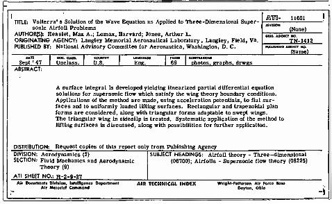
I TITLE: Volterra' s Solution of the Wave Equation as Applied to Three-Dimensional Super-
sonic Airfoil Problems AUTHORS): Heaslet, Max A.; Lomax, Harvard; Jones, Arthur L. ORIGINATING AGENCY: Langley Memorial Aeronautical Laboratory , Langley, Field, Va. PUBLISHED BY: National Advisory Committee for Aeronautics, Washington, D. C.
&T0- 11601
(None) <MIO. AOEMCT NO.
TW-1412 PU0USM1MO AGENCY NO.
(Same)
Sept ' 47 Unclass. U.S. Eng. rAaa 69
11LUSTOA110MS
photos, graphs, drwgs ABSTRACT:
A surface integral is developed yielding linearized partial differential equation solutions for supersonic flow which satisfy the wing theory boundary conditions. Applications of the method are made, using acceleration potentials, to flat sur- faces and to uniformly loaded lifting surfaces. Rectangular and trapezoidal plan forms are considered, along with triangular forms adaptable to swept wings. The triangular wing in sideslip is treated. Systematic application of the method to lifting surfaces is discussed, along with possibilities for further application.
DISTRIBUTION: Request copies of this report only from Publishing Agency DIVISION: Aerodynamics (2) SECTION: Fluid Mechanics and Aerodynamic
Theory (0)
ATI SHEET NO.: R-2-9-27
SUBJECT HEADINGS: Airfoil theory - Three-dimensional (06700); Airfoils - Supersonic flow theory (08225)
Air Documonti Division, Intotligonco Doportmont Air Materiel Command
AID. TECHNICAL INDEX Wright-Pattoreon Air Forco Bato Dayton, Ohio