Voltage suppler..
24
PROJECT REPORTONAVOLTAGE SUPPLIER 24.12. 2014 SECOND YEAR SECOND SEMESTER. DEPT. OF APPLIED PHYSICS , ELECTRONICS & COMMUNICATION ENGINEERING
-
Upload
bangabandhu-sheikh-mujibur-rahman-science-and-technology-university -
Category
Engineering
-
view
38 -
download
3
Transcript of Voltage suppler..

PROJECT REPORT ON A VOLTAGE SUPPLIER 24.12. 2014
SECOND YEAR SECOND SEMESTER.
DEPT. OF APPLIED PHYSICS , ELECTRONICS & COMMUNICATION ENGINEERING

GROUP 2
1. MD. RUBEL SARKAR
(200121102004)
1. MD. ABBAS ALI
(20121102001)
3.TAUHIDUR RAHMAN
(20121102023)
4. MD. BURHAN UDDIN
(2012120205..)
JIBON KRISHNA MODAK
LECTURER DEPT OF
APECE,BSMRSTU
GOPALGONJ
a
SUBMITTED BY, SUBMITTED TO,

SL NO Name of process Page no.
01 Abstruct 01
02 Introduction 01
03 Circuit Operation 02
04 Description each component 02-10
05 Application 11
06 FEATURES & MAXIMUM RATINGS 10
07 List of component 11
08 Refernce 12
CONTENT
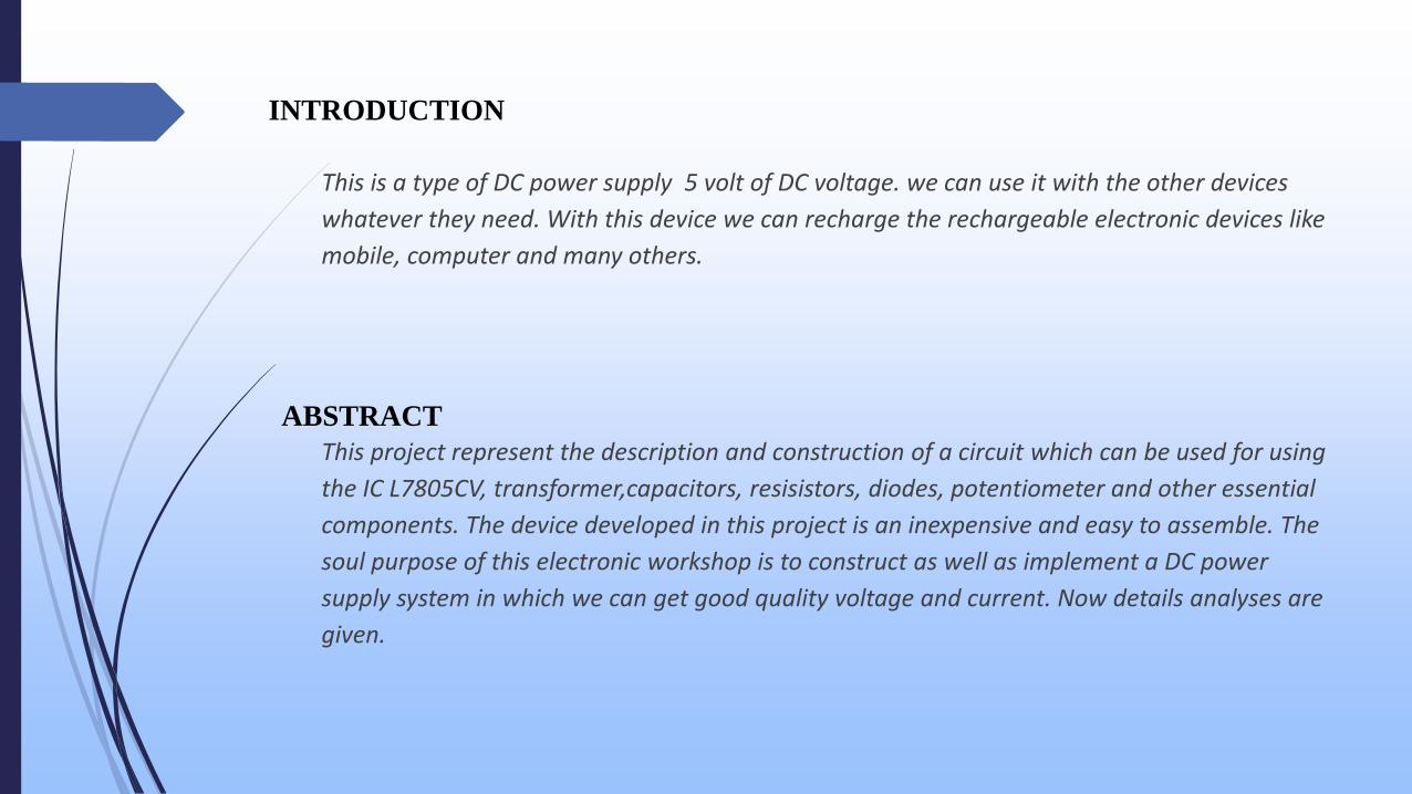
INTRODUCTION
This is a type of DC power supply 5 volt of DC voltage. we can use it with the other devices
whatever they need. With this device we can recharge the rechargeable electronic devices like
mobile, computer and many others.
ABSTRACT
This project represent the description and construction of a circuit which can be used for using
the IC L7805CV, transformer,capacitors, resisistors, diodes, potentiometer and other essential
components. The device developed in this project is an inexpensive and easy to assemble. The
soul purpose of this electronic workshop is to construct as well as implement a DC power
supply system in which we can get good quality voltage and current. Now details analyses are
given.
T1
10:1C1
470µF
C2
1µFC3
0.47µF
V1
220Vpk 50Hz 0°
R1
1.0kΩ
LED1
D1
1B4B42
3
1
4
2
U1
LM7805KC
LINE VREG
COMMON
VOLTAGE
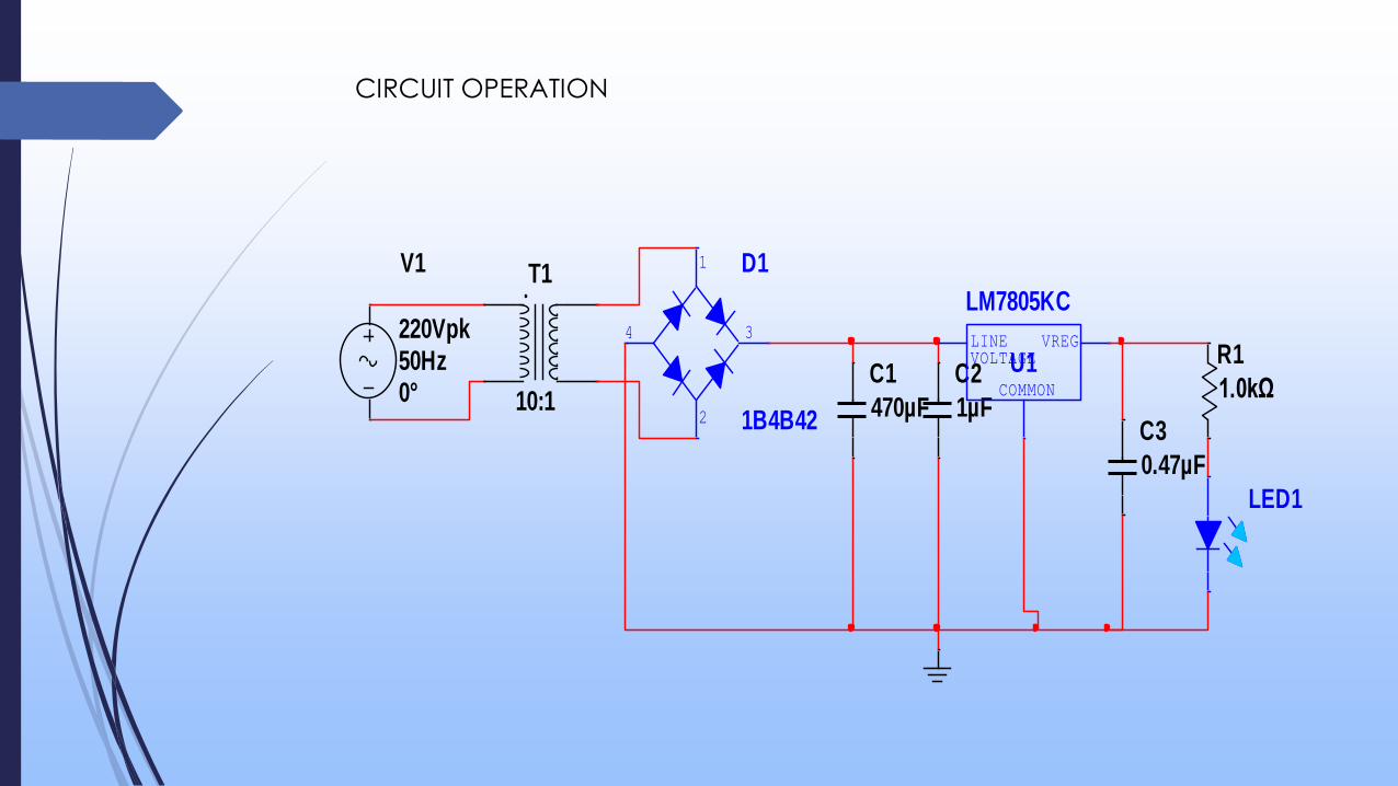
CIRCUIT OPERATION

The output generated from the unregulated DC output is susceptible to the fluctuations of the input signal. IC voltage regulator is connected with bridge
rectifier in series in these project so to steady the DC output against the variations in the input DC voltage. To obtain a stable output of 5V, IC 7805 is attached with 6-0-
6V along with 500mA step down transformer as well as with rectifier. To suppress the
oscillation which might generate in the regulator IC, C2 capacitor of 0.1 uF value is
used. When the power supply filter is far away from the regulated IC capacitor C2 is used. Ripple rejection in the regulator is been improved by C4 capacitor(35uf) by
avoiding the ripple voltage to be amplified at the regulator output .The output
voltage is strengthen and deduction of the output voltage is done capacitor
C3(0.1uF). To avoid the chance of the input get shorted D5 diode is used to save the
regulator. If D5 is not presented in the circuit, the output capacitor can leave its
charge immediately during low impedance course inside the regulators. 7805 is a
5V fixed three terminal positive voltage regulator IC. The IC has features such as safe
operating area protection, thermal shut down, internal current limiting which makes
the IC very rugged. Output currents up to 1A can be drawn from the IC provided
that there is a proper heat sink. A 9V transformer steps down the main voltage, 1A
bridge rectifies it and capacitor C1 filters it and 7805 regulates it to produce a steady
5Volt DC.
DESCRIPTION OF EACH COMPONENT
ICL7805CV
A regulated power supply is very much essential for several electronic devices due to
the semiconductor material employed in them have a fixed rate of current as well as
voltage. The device may get damaged if there is any deviation from the fixed rate.
The AC power supply gets converted into constant DC by this circuit. By the help of a
voltage regulator DC, unregulated output will be fixed to a constant voltage. The
circuit is made up of linear voltage regulator 7805 along with capacitors and resistors
with bridge rectifier made up from diodes. From giving an unchanging voltage supply
to building confident that output reaches uninterrupted to the appliance, the diodes
along with capacitors handle elevated efficient signal conveyal.
Description:
As we have previously talked about that regulated power supply is a device that
mechanized on DC voltages and also it can uphold its output accurately at a fixed
voltage all the time although if there is a significant alteration in the DC input
voltage.
ICs regulator is mainly used in the circuit to maintain the exact voltage which is followed by
the power supply. A regulator is mainly employed with the capacitor connected in parallel to
the input terminal and the output terminal of the IC regulator. For the checking of gigantic
alterations in the input as well as in the output

filter, capacitors are used. While the bypass capacitors are used to check the small
period spikes on the input and output level. Bypass capacitors are mainly of small
values that are used to bypass the small period pulses straightly into the Earth.As we
have made the whole circuit till now to be operated on the 5V DC supply, so we have
to use an IC regulator for 5V DC. And the most generally used IC regulators get into
the market for 5V DC regulation use is 7805. So we are connecting the similar IC in the
circuit as U1.
IC 7805 is a DC regulated IC of 5V. This IC is very flexible and is widely employed in all
types of circuit like a voltage regulator. It is a three terminal device and mainly called
input , output and ground. Pin diagram of the IC 7805 is shown in the diagram below.

PIN
NO. PIN DESCRIPTION
1 INPUT In this pin of the IC positive unregulated voltage is
given in regulation.
2 GROUND In this pin where the ground is given. This pin is
neutral for equally the input and output.
3 OUTPUT The output of the regulated 5V volt is taken out at
this pin of the IC regulator.
In the circuit diagram C2 as well as C3 are filter capacitor while bypass capacitors are the C1
and C4.The electrolytic polarized capacitors are employed for this purpose. For the purpose
of filter capacitors normally 10mfd value of the capacitor used. And in these projects we
also used 100mfd value of the capacitor. While in all kinds of circuit the value of bypass
capacitor is 0.1 mfd. And in generally un-polarized mainly disc capacitors employed for this
purpose.Currently we have the circuit for the 5V DC positive regulation and we are also
familiar with the component values used in the circuit. In the table below we have
mentioned the value in detail of all the components used in the circuit of 5V DC positive
regulator
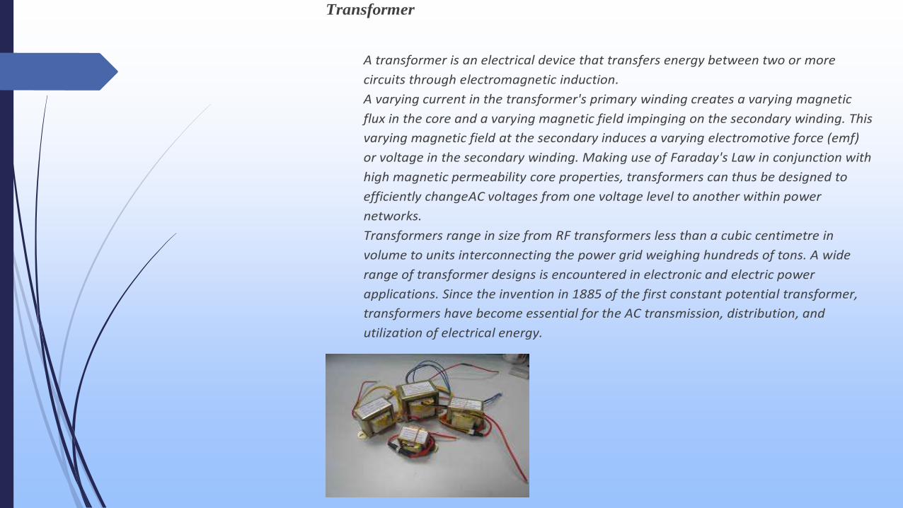
Transformer
A transformer is an electrical device that transfers energy between two or more
circuits through electromagnetic induction.
A varying current in the transformer's primary winding creates a varying magnetic
flux in the core and a varying magnetic field impinging on the secondary winding. This
varying magnetic field at the secondary induces a varying electromotive force (emf)
or voltage in the secondary winding. Making use of Faraday's Law in conjunction with
high magnetic permeability core properties, transformers can thus be designed to
efficiently changeAC voltages from one voltage level to another within power
networks.
Transformers range in size from RF transformers less than a cubic centimetre in
volume to units interconnecting the power grid weighing hundreds of tons. A wide
range of transformer designs is encountered in electronic and electric power
applications. Since the invention in 1885 of the first constant potential transformer,
transformers have become essential for the AC transmission, distribution, and
utilization of electrical energy.

Function:
transform power,convert voltage,insulation
Application:
almost all the electrinic product such as power switching, computer peripherals,video
equipments, measuring equipments ,industrial control,communicating
equipments,medical facilities,automobiles and other fields
Shape of transformer's core:E type
Material:
the cores are lapped by high quality silicon steel slate and have been treated by
insulation,utilizing the fuse wire fully assures the safty of connecting equipment
the input lead wire is clearly marked by red,the length of which depends on our
clients' favor .
Characteristic:
Forge the combition of convenient installation ,high cost performance, low
consumption,and nice appearance.
with lamination size range of EI28/35/41/48/66/76/96/133 to match with the resquested power

Specification of transformers:
Various rated input option:100-240VAC,50/60Hz
Output power:1W,
Maximus ripple voltage:250mV
converting efficiency:50%
line regulation:10%
load regulation:10%
Protection:
over temperature protection:130degree centigrate
Security test including overload test, hi-pot test, insulation test,line production
test,humidity test
Comform to different countries’ Safety standards such as ,UL,GS,CE,ROHS ,CCC and
more
Manufacturer of this type of transformers:established in1993.
You will get trustful professional resarchers in the field of transformers to customise
what you need...
Diode
A diode is a specialized electronic component with two electrodes called
the anode and thecathode. Most diodes are made with semiconductor materials such
as silicon, germanium, or selenium. Some diodes are comprised of metal electrodes in
a chamber evacuated or filled with a pure elemental gas at low pressure. Diodes can
be used as rectifiers, signal limiters, voltage regulators, switches, signal modulators,
signal mixers, signal demodulators, and oscillators.
The fundamental property of a diode is its tendency to conduct electric current in only
one direction. When the cathode is negatively charged relative to the anode at
a voltage greater than a certain minimum called forward breakover, then current
flows through the diode. If the cathode is positive with respect to the anode, is at the
same voltage as the anode, or is negative by an amount less than the forward
breakover voltage, then the diode does not conduct current. This is a simplistic view,
but is true for diodes operating as rectifiers, switches, and limiters. The forward
breakover voltage is approximately six tenths of a volt (0.6 V) for silicon devices, 0.3 V
for germanium devices, and 1 V for selenium devices.
The above general rule notwithstanding, if the cathode voltage is positive relative to
the anode voltage by a great enough amount, the diode will conduct current. The
voltage required to produce this phenomenon, known as the avalanche voltage,
varies greatly depending on the nature of the semiconductor material from which the
device is fabricated. The avalanche voltage can range from a few volts up to several
hundred volts.
When an analog signal passes through a diode operating at or near its forward breakover
point, the signal waveform is distorted. This nonlinearity allows for

modulation, demodulation, and signal mixing. In addition, signals are generated
at harmonics, or integral multiples of the input frequency. Some diodes also have a
characteristic that is imprecisely termed negative resistance. Diodes of this type, with
the application of a voltage at the correct level and the polarity, generate analog
signals at microwave radio frequencies.
Semiconductor diodes can be designed to produce direct current (DC) when visible
light,infrared transmission (IR), or ultraviolet (UV) energy strikes them. These diodes
are known as photovoltaic cells and are the basis for solar electric energy systems and
photosensors. Yet another form of diode, commonly used in electronic and computer
equipment, emits visible light or IR energy when current passes through it. Such a
device is the familiar light-emitting diode (LED).

CAPACITOR
Capacitor is a passive two terminal electrical component used to store energy electro
statically in an electric field. The forms of practical capacitors vary widely, but all
contain at least two electrical conductors separated by a dielectric (i.e. insulator). The
conductors can be thin films, foils or conductive electrolyte etc. The "no conducting"
dielectric acts to increase the capacitor's charge capacity. A dielectric can be glass,
ceramic, plastic film, air, vacuums, paper, oxide layer etc. Capacitors are widely used
as parts of electrical circuits in many common electrical devices. Unlike a resistor, an
ideal capacitor does not dissipate energy. Instead, a capacitor stores energy in the
form of an electrostatic field between its plates. An ideal capacitor is characterized by
a single constant value for its capacitance. Capacitance is expressed as the ratio of
the electric charge Q on each conductor to the potential difference V between them.
The SI unit of capacitance is the farad (F). Capacitors are widely used in electronic
circuits for blocking direct current while allowing alternating current to pass. In
analog filter networks, they smooth the output of power supplies. In resonant circuits
they tune radios to particular frequencies. In electric power transmission systems,
they stabilize voltage and power flow.
RESISTOR
A resistor is a passive two-terminal electrical component that implements electrical
resistance as a circuit element. Resistors act to reduce current flow, at the same time,
act to lower voltage levels within circuits. In electronic circuits resistors are used to
limit current flow, to adjust signal levels, bias active elements, terminate transmission
lines among other uses. High-power resistors that can dissipate many watts of
electrical power as heat may be used as part of motor controls, in power distribution
systems, or as test loads for generators. Resistors may have fixed resistances that
only change a little with temperature. Variable resistors can be used to adjust circuit
elements (such as a volume control or a lamp dimmer), or as sensing devices for heat,
light, humidity, force, or chemical activity.
Resistors are common elements of electrical networks and electronic circuits .
Practical resistors as discrete components can be composed of various compounds
and forms. Resistors are also implemented within integrated circuits.
The electrical function of a resistor is specified by its resistance: common commercial
resistors are manufactured over a range of more than nine orders of magnitude. The
nominal value of the resistance will fall within a manufacturing tolerance.

Figure: Resistor
LED
A typical high-flux LED device is capable of producing a few to tens of lumens. The
updated design can be integrated more LED in a single device, or install multiple
devices in a single assembly, thus making a considerable number of lumens output
small incandescent lamps. For example, a monochromatic high-power 12 chips LED
device can output 200lm light energy, the consumed power is between 10 ~ 15W.
Application of LED light source is very flexible. LED can be made of points, lines,
surfaces and other various forms of portable products; the controlling of LED is
extremely convenient, only need to adjust the current, you can freely adjust the light;
different combinations of light color will various. Through circuit timing control, we
can get better and variety of dynamic effects. LED lighting has been widely used in
various devices, such as battery-powered flash, miniature voice-activated lights,
security lights, outdoor and indoor stair lighting roads and buildings and mark the
continuous lighting.
The appearance of the white LED is substantial steps that the function of LED turns
identifying to lighting. White LED is the closest to the sunshine, better reflect the true color
of the object, so from a technical standpoint, LED white LED is undoubtedly the
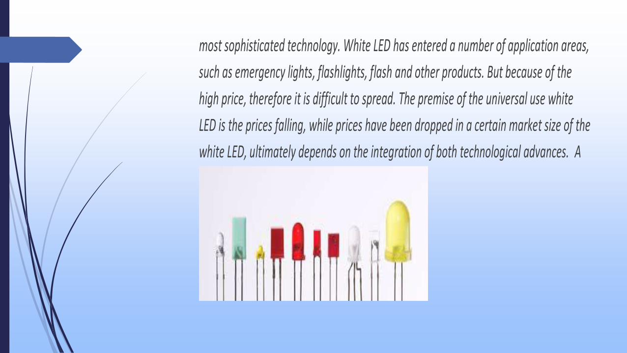
most sophisticated technology. White LED has entered a number of application areas,
such as emergency lights, flashlights, flash and other products. But because of the
high price, therefore it is difficult to spread. The premise of the universal use white
LED is the prices falling, while prices have been dropped in a certain market size of the
white LED, ultimately depends on the integration of both technological advances. A
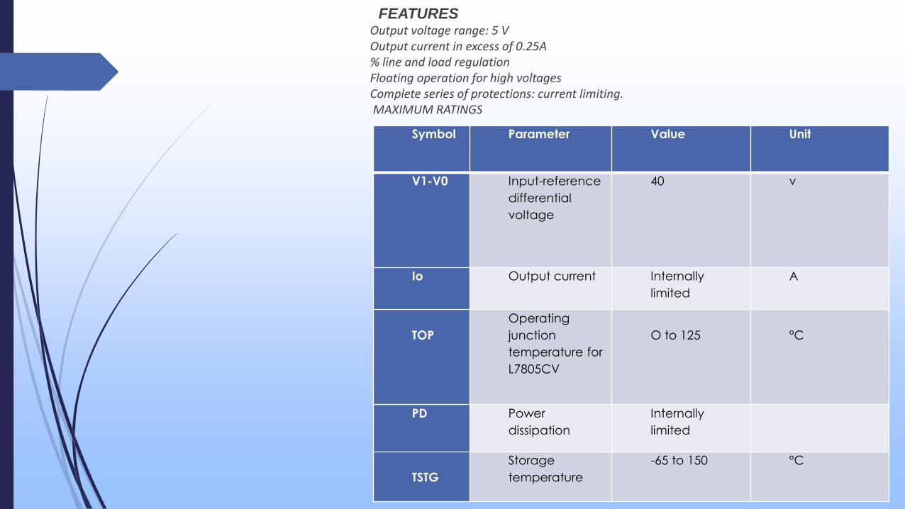
Symbol Parameter Value Unit
V1-V0 Input-reference
differential
voltage
40 v
Io Output current Internally
limited
A
TOP
Operating
junction
temperature for
L7805CV
O to 125 °C
PD Power
dissipation
Internally
limited
TSTG
Storage
temperature
-65 to 150 °C
FEATURESOutput voltage range: 5 VOutput current in excess of 0.25A% line and load regulationFloating operation for high voltagesComplete series of protections: current limiting. MAXIMUM RATINGS

APPLICATION
1. Low current consumption
2. Overvoltage/ Short-circuit protection
3. Reverse polarity protection
4. Overtemperature protection
5. Load protection
6. Pin-to-pin compatible to
7. industry standard parts
8. High input voltage rating: Up
to 45V
9. Very low dropout voltage
10. Temp. range: –40°C up
to +125°C
11. Use as a voltage supplyer
12. Use as a mobile charger

SL
N
O.
Name of the
component
Quantity Price(Taka)
01 ICL78O5CV 1 10
02 Transformer 1 110
03 Diode 4 8
04 Capacitor 3 15
05 Resistor 1 2
06 PCB Board 1 30
07 LED 1 1
08 Total 13 176
LIST OF COMPONENT AND
COST
REFFERENCE
1. http://www.electronics-tutorials.ws/diode/diode_6.html
2. Electronic Circuits: Fundamentals and Applications, 3rd Ed.
3. Lowe, Doug (2013). "Electronics Components: Diodes". Electronics All-In-One Desk
Reference For Dummies. John Wiley & Sons. Retrieved January 4, 2013
4. Lowe, Doug (2013). "Electronics Components: Diodes". Electronics All-In-One Desk
Reference For Dummies. John Wiley & Sons. Retrieved January 4, 2013
5. The first LEDs were infrared (invisible)". Smithsonian National Museum of American
History. October 2007. Retrieved July 24, 2013
6. Quantum-dot LED may be screen of choice for future electronics Massachusetts
Institute of Technology News Office, December 18, 2002
7. Knowlton, A.E. (Ed.) (1949). Standard Handbook for Electrical Engineers (8th ed.).
McGraw-Hill. p. 597, Fig. 6–42.
8. Lane, Keith (2007). "The Basics of Large Dry-Type Transformers". EC&M.
Retrieved 29 January2013.
9.www.wikipedia.com
10.www.goole .co

End.
Thank you to all…