Voltage Sags Mitigation Techniques...
21
VOLTAGE SAGS MITIGATION TECHNIQUES ANALYSIS NORSHAFINASH BINTI SAUDIN A project report submitted in partial fulfillment of the requirements for the award of the degree of Master of Engineering (Electrical – Power) Faculty of Electrical Engineering Universiti Teknologi Malaysia JUNE 2007
Transcript of Voltage Sags Mitigation Techniques...
VOLTAGE SAGS MITIGATION TECHNIQUES ANALYSIS
NORSHAFINASH BINTI SAUDIN
A project report submitted in partial fulfillment of the
requirements for the award of the degree of
Master of Engineering (Electrical – Power)
Faculty of Electrical Engineering
Universiti Teknologi Malaysia
JUNE 2007

iii
To my beloved husband

iv
ACKNOWLEDGEMENT
I would like to express my gratitude to Allah S.W.T. for giving me the
opportunity to complete this Master’s Project. I am deeply indebted to individuals who,
directly or indirectly, are responsible for this project.
I am most grateful to the most kindheartedness supervisor Dr Ahmad Safawi bin
Mokhtar for his guidance in this project and to panel of seminar presentation, PM. Dr.
Mohd Wazir bin Mustafa and PM. Md. Shah Majid, with their superior guidance,
information and ideas for this project become abundance.
My admiration falls upon En. Saudin bin Mat, my father, and especially to my
mother, Pn. Siah binti Taharin for them to bear with me my absence in the family. Your
encouragement, pray and support are very much appreciated.
I would also like to express my sincere thanks to my entire friend for their
support and ideas during the development of the project.
And last but not the least, to my husband, thanks.
v
ABSTRACT
For some decades, power quality did not cause any problem, because it had no
effect on most of the loads connected to the electric distribution system. When an
induction motor is subjected to voltage sag, the motor still operates but with a lower
output until the sag ends. With the increased use of sophisticated electronics, high
efficiency variable speed drive, and power electronic controller, power quality has
become an increasing concern to utilities and customers. Voltage sags is the most
common type of power quality disturbance in the distribution system. It can be caused
by fault in the electrical network or by the starting of a large induction motor. Although
the electric utilities have made a substantial amount of investment to improve the
reliability of the network, they cannot control the external factor that causes the fault,
such as lightning or accumulation of salt at a transmission tower located near to sea.
This project intends to investigate mitigation technique that is suitable for different type
of voltage sags source with different type of loads. The simulation will be using
PSCAD/EMTDC software. The mitigation techniques that will be studied are such as
Dynamic Voltage Restorer (DVR), Distribution Static Compensator (DSTATCOM) and
Solid State Transfer Switch (SSTS). All the mitigation techniques will be tested on
different type of faults. The analysis will focus on the effectiveness of these techniques
in mitigating the voltage sags. The study will also investigate the effects of using the
techniques to phase shift. At the end of the project it is expected that a few suggestions
can be made on the suitability of the techniques.
vi
ABSTRAK
Beberapa dekad yang lalu, kualiti kuasa tidak menjadi permasalahan kerana ia
tidak memberi kesan yang sangat nyata kepada beban yang bersambung dengan sistem
pengagihan. Apabila motor aruhan mengalami voltan lendut, motor tersebut masih
berfungsi tetapi dengan keluaran yang lebih rendah sehingga kejatuhan voltan tamat.
Walau bagaimanapun, dengan peningkatan penggunaan peralatan elektronik yang maju,
pemacu pelbagai halaju berkecekapan tinggi, dan pengawal elektronik kuasa, kualiti
kuasa mula menjadi perhatian kepada utiliti dan pelanggan. Di mana, voltan lendut
adalah gangguan kualiti kuasa yang seringkali terjadi terhadap sistem pengagihan yang
disebabkan oleh kerosakan pada rangkaian elektrik dan pemulaan yang besar untuk
motor aruhan. Walaupun utiliti telah membuat pelaburan untuk memperbaiki
keboleharapan rangkaian, faktor luaran yang menyebabkan kerosakan masih tidak dapat
dikawal, contohnya kilat dan pengumpulan garam pada menara penghantaraan yang
terletak berhampiran dengan laut. Oleh itu, projek ini bertujuan mengkaji kesesuaian
teknik mitigasi untuk pelbagai punca voltan lendut pada beban yang berbeza di mana
perisian PSCAD/EMTDC digunakan sebagai bantuan untuk simulasi. Teknik - teknik
mitigasi yang dikaji adalah seperti Dynamic Voltage Restorer (DVR), Distribution Static
Compensator (DSTATCOM), dan Solid State Transfer Switch (SSTS). Teknik - teknik ini
akan diuji dengan pelbagai kerosakan yang menyebabkan voltan lendut. Tumpuan akan
diberikan kepada keberkesanan teknik-teknik tersebut untuk mengatasi voltan lendut dan
kesannya terhadap anjakan fasa. Di akhir projek ini, beberapa cadangan akan diutarakan
berkenaan kesesuaian teknik - teknik tersebut digunakan untuk mengatasai voltan lendut.
vii
TABLE OF CONTENTS
CHAPTER TITLE PAGE
DECLARATION ii
DEDICATION iii
ACKNOWLEDGEMENT iv
ABSTRACT v
ABSTRAK vi
TABLE OF CONTENTS vii
LIST OF TABLES xi
LIST OF FIGURES xii
LIST OF ABBREVIATIONS xv
LIST OF APPENDICES xvi
I INTRODUCTION 1
1.1 Introduction 1
1.2 Problem Statement 3
1.3 Project Objectives 6
1.4 Project Scope 6

viii
II VOLTAGE SAGS 7
2.1 Introduction 7
2.2 Definition of Voltage Sags 8
2.3 Standards Associated with Voltage Sags 9
2.3.1 IEEE Standard 10
2.3.2 Industry Standard 12
2.3.2.1 SEMI 12
2.3.2.2 CBEMA (ITI) Curve 14
2.4 General Causes and Effects of Voltage Sags 15
2.4.1 Voltage Sags due to Faults 15
2.4.2 Voltage Sags due to Motor Starting 17
2.4.3 Voltage Sags due to Transformer Energizing 18
III PSCAD/EMTDC SOFTWARE 19
3.1 Introduction 19
3.2 Characteristics of Software 20
3.3 Example of Circuit 22
3.4 Conclusion 25
ix
IV VOLTAGE SAG MITIGATION TECHNIQUES 26
4.1 Introduction 26
4.2 Dynamic Voltage Restorer (DVR) 28
4.2.1 Principles of DVR Operation 28
4.3 Distribution Static Compensator (DSTATCOM) 30
4.2.1 Basic Configuration and Function of
DSTATCOM 31
4.4 Solid State Transfer Switch (SSTS) 34
4.4.1 Basic Configuration and Function of SSTS 35
V MITIGATION TECNIQUES REALIZATION 39
5.1 Sinusoidal PWM-Based Control Scheme 39
5.2 Test System 42
5.3 Dynamic Voltage Restorer 43
5.4 Distribution Static Compensator 45
5.5 Solid State Transfer Switch 47
x
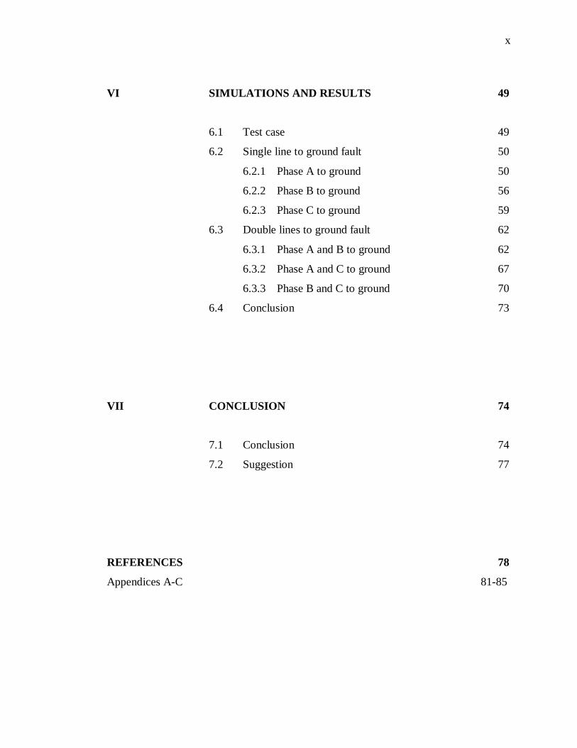
VI SIMULATIONS AND RESULTS 49
6.1 Test case 49
6.2 Single line to ground fault 50
6.2.1 Phase A to ground 50
6.2.2 Phase B to ground 56
6.2.3 Phase C to ground 59
6.3 Double lines to ground fault 62
6.3.1 Phase A and B to ground 62
6.3.2 Phase A and C to ground 67
6.3.3 Phase B and C to ground 70
6.4 Conclusion 73
VII CONCLUSION 74
7.1 Conclusion 74
7.2 Suggestion 77
REFERENCES 78
Appendices A-C 81-85
xi
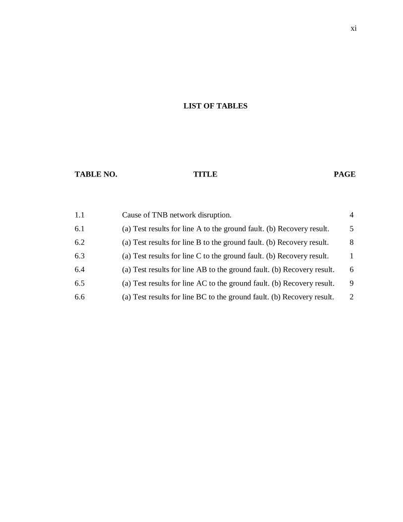
LIST OF TABLES
TABLE NO. TITLE PAGE
1.1 Cause of TNB network disruption. 4
6.1 (a) Test results for line A to the ground fault. (b) Recovery result. 5
6.2 (a) Test results for line B to the ground fault. (b) Recovery result. 8
6.3 (a) Test results for line C to the ground fault. (b) Recovery result. 1
6.4 (a) Test results for line AB to the ground fault. (b) Recovery result. 6
6.5 (a) Test results for line AC to the ground fault. (b) Recovery result. 9
6.6 (a) Test results for line BC to the ground fault. (b) Recovery result. 2

xii
LIST OF FIGURES
FIGURE NO. TITLE PAGE
1.1 Demarcation of the various power quality issues defined
by IEEE Std. 1159-1995 2
2.1 Depiction of voltage sag 9
2.2 Immunity curve for semiconductor manufacturing
equipment according to SEMI F47 13
2.3 Revised CBEMA curve, ITIC curve, 1996 14
2.4 Voltage sag due to a cleared line-ground fault 16
2.5 Voltage sag due to motor starting 17
2.6 Voltage sag due to transformer energizing 18
3.1 DVR with main components in PSCAD 23
3.2 The Wye-Connected DVR in PSCAD 24
4.1 Different protection options for improving performance during
power quality variation. 27
4.2 Principle of DVR with a response time of less than one
millisecond 29
4.3 Schematic diagram of the DSTATCOM as a custom
power controller 30
4.4 Building blocks of DSTATCOM 32
4.5 Operation modes of a DSTATCOM 33

xiii
4.6 Schematic representations of the SSTS as a custom power device. 34
4.7 Solid State Transfer Switch systems 35
4.8 Thyristors of the SSTS conducting in the positive and
negative half cycle of the preferred source. 37
4.9 Thyristors on the alternate supply are turned ON on sensing
a disturbance on the preferred source. 38
5.1 Control scheme for the test system implemented in
PSCAD/EMTDC to carry out the DSTATCOM and DVR
simulations. 40
5.2 The test system implemented in PSCAD/EMTDC 42
5.3 One line diagram of the DVR test system 43
5.4 Schematic diagram of the DVR 44
5.5 Schematic diagram of the test system with DVR connected
to the system. 44
5.6 One line diagram of the DSTATCOM test system. 45
5.7 Schematic diagram of the test system with DSTATCOM
connected to the system. 46
5.8 One line diagram of the SSTS test system. 47
5.9 SSTS switches implemented in PSCAD/EMTDC 48
5.10 Schematic diagram of the test system with SSTS connected
to the system. 48
6.1 (a) Phase shift for line A to the ground fault
(b) Rms voltage drop 50
6.2 (a) Corrected phase with DVR
(b) Compensated voltage sag with DVR 51
6.3 (a) Corrected phase using DSTATCOM
(b) Compensated voltage sag using DSTATCOM 53
6.4 (a) Corrected phase using SSTS
(b) Compensated voltage sag using SSTS 54
6.5 Phase shift of line B to the ground fault. 56

xiv
6.6 (a) Phase correction using DVR
(b) Phase correction using DSTATCOM; line B to
the ground fault. 57
6.7 Phase shift of line B to the ground fault. 59
6.8 (a) Phase correction using DVR
(b) Phase correction using DSTATCOM; line C to
the ground fault. 60
6.9 (a) Phase shift for line A and B to the ground fault
(b) Rms voltage drop 63
6.10 (a) Phase correction using DVR,
(b) Phase correction using DSTATCOM; line A and B
to the ground fault. 64
6.11 (a) Compensated voltage sag using DVR
(b) Compensated voltage sag using DSTATCOM;
Line A and B to the ground fault. 65
6.12 Phase shift for line A and C to the ground fault 67
6.13 (a) Phase correction using DVR,
(b) Phase correction using DSTATCOM; line A and C
to the ground fault. 68
6.14 Phase shift for line B and C to the ground fault. 70
6.15 (a) Phase correction using DVR,
(b) Phase correction using DSTATCOM; line B and C
to the ground fault. 71

xv
LIST OF ABBREVIATIONS
CBEMA - Computer Business Equipment Manufacturers Association
DSTATCOM - Distribution Static Compensator
DVR - Dynamic Voltage Restorer
EMTDC - Electromagnetic Transient Program with DC Analysis
ERM - Electronic Restart Modules
Hz - Hertz
IEC - International Electrotechnical Commission
IEEE - Institute of Electrical and Electronics Engineers
ITIC - Information Technology Industry Council
kV - kilovolt
MVA - megavolt ampere
MVAR - mega volt amps reactive
MW - megawatt
p.u. - per unit
PCC - point of common coupling
PSCAD - Power System Aided Design
PWM - Pulse Width Modulation
RMS - root mean square
SEMI - Semiconductor Equipment and Materials International
SSTS - Solid State Transfer Switch
TNB - Tenaga Nasional Berhad
TRV - transient recovery voltage
xvi
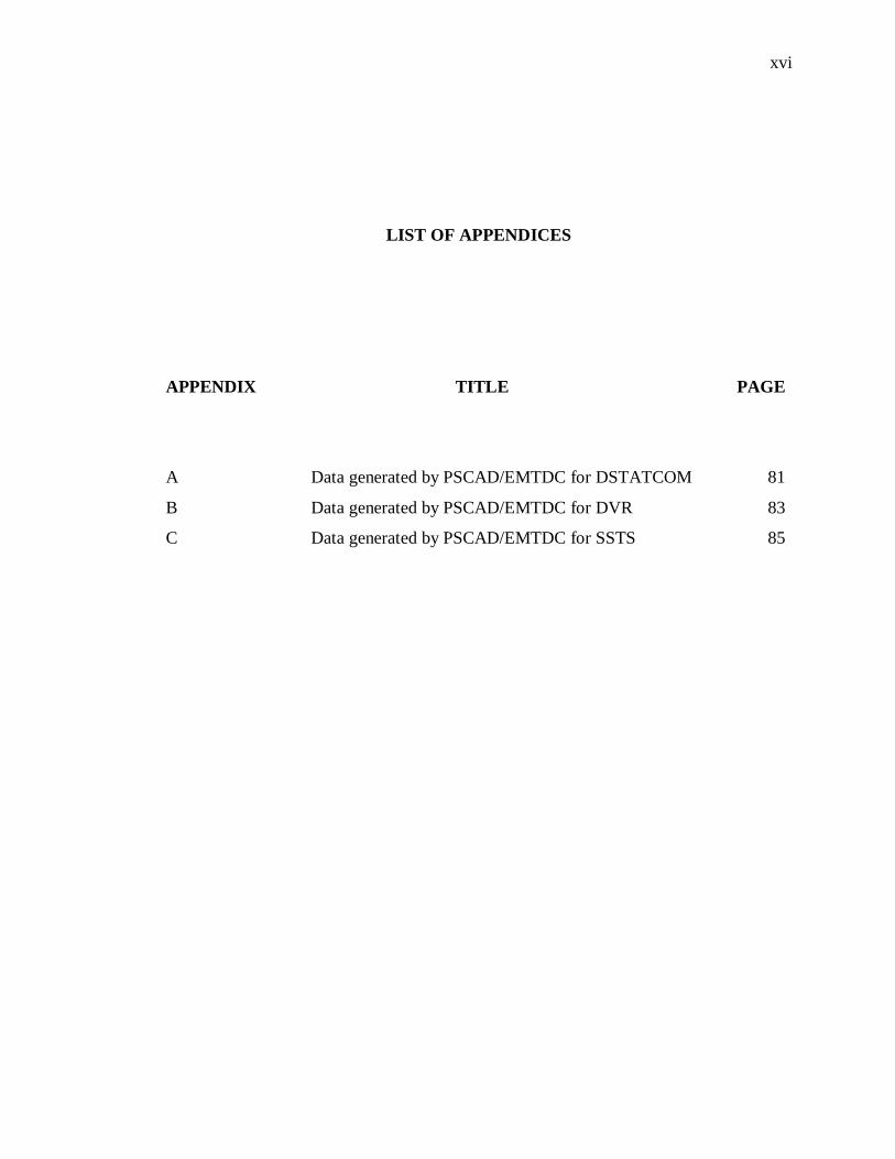
LIST OF APPENDICES
APPENDIX TITLE PAGE
A Data generated by PSCAD/EMTDC for DSTATCOM 81
B Data generated by PSCAD/EMTDC for DVR 83
C Data generated by PSCAD/EMTDC for SSTS 85

CHAPTER I
INTRODUCTION
1.1 Introduction
Both electric utilities and end users of electrical power are becoming increasingly
concerned about the quality of electric power. The term power quality has become one
of the most prolific buzzword in the power industry since the late 1980s [1]. The issue in
electricity power sector delivery is not confined to only energy efficiency and
environment but more importantly on quality and continuity of supply or power quality
and supply quality. Electrical Power quality is the degree of any deviation from the
nominal values of the voltage magnitude and frequency. Power quality may also be
defined as the degree to which both the utilization and delivery of electric power affects
the performance of electrical equipment [2]. From a customer perspective, a power
quality problem is defined as any power problem manifested in voltage, current, or
frequency deviations that result in power failure or disoperation of customer of
equipment [3].

2
Power quality problems concerning frequency deviation are the presence of
harmonics and other departures from the intended frequency of the alternating supply
voltage. On the other hand, power quality problems concerning voltage magnitude
deviations can be in the form of voltage fluctuations, especially those causing flicker.
Other voltage problems are the voltage sags, short interruptions and transient over
voltages. Transient over voltage has some of the characteristics of high-frequency
phenomena. In a three-phase system unbalanced voltages also is a power quality
problem [2]. Among them, two power quality problems have been identified to be of
major concern to the customers are voltage sags and harmonics, but this project will be
focusing on voltage sags.
Figures 1.1 describe the demarcation of the various power quality issues defined
by IEEE Std. 1159-1995. [4]
Figure 1.1 Demarcation of the various power quality issues defined by IEEE
Std. 1159-1995[4]
3
Three factors that are driving interest and serious concerns in power quality are
[1]:
i. Increased load sensitivity and production automation. The focus on
power quality is therefore more of voltage quality as the momentary drop
in voltage disrupts automated manufacturing processes.
ii. Automation and efficiency relies on digital components which requires dc
supply. As public utilities supply ac power, dc power supplies powered
by ac are needed by the dc loads.
iii. As more dc power supply are needed the converters that convert ac to dc
cause harmonics to be injected into the system and hence reduce wave
form quality
1.2 Problem Statement
With the increased use of sophisticated electronics, high efficiency variable
speed drive, and power electronic controller, power quality has become an increasing
concern to utilities and customers. Voltage sags is the most common type of power
quality disturbance in the distribution system. It can be caused by fault in the electrical
network or by the starting of a large induction motor. Although the electric utilities have
made a substantial amount of investment to improve the reliability of the network, they
cannot control the external factor that causes the fault, such as lightning or accumulation
of salt at a transmission tower located near to sea.
4
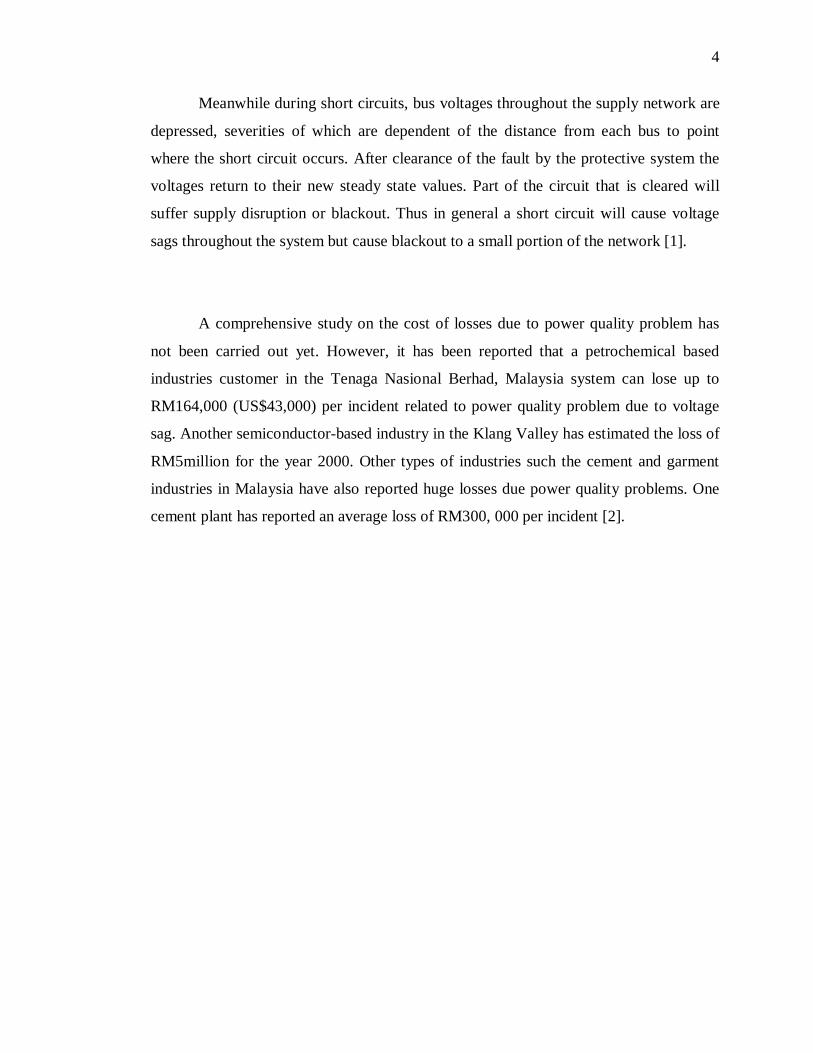
Meanwhile during short circuits, bus voltages throughout the supply network are
depressed, severities of which are dependent of the distance from each bus to point
where the short circuit occurs. After clearance of the fault by the protective system the
voltages return to their new steady state values. Part of the circuit that is cleared will
suffer supply disruption or blackout. Thus in general a short circuit will cause voltage
sags throughout the system but cause blackout to a small portion of the network [1].
A comprehensive study on the cost of losses due to power quality problem has
not been carried out yet. However, it has been reported that a petrochemical based
industries customer in the Tenaga Nasional Berhad, Malaysia system can lose up to
RM164,000 (US$43,000) per incident related to power quality problem due to voltage
sag. Another semiconductor-based industry in the Klang Valley has estimated the loss of
RM5million for the year 2000. Other types of industries such the cement and garment
industries in Malaysia have also reported huge losses due power quality problems. One
cement plant has reported an average loss of RM300, 000 per incident [2].

5
Table 1.1 Cause of TNB network disruption [2]
In general, voltage sags can causes:
i. Motor load to stall/stop
ii. Digital devices to reset causing loss of data
iii. Equipment damage and/or failure
iv. Materials Spoilage
v. Lost production due to downtime
vi. Additional costs
vii. Product reworks
viii. Product quality impacts
ix. Impacts on customer relations such as late delivery and lost of sales
x. Cost of investigations into problem
Therefore, this project intends to investigate mitigation technique that is suitable
for different type of voltage sags source with different type of loads.
6
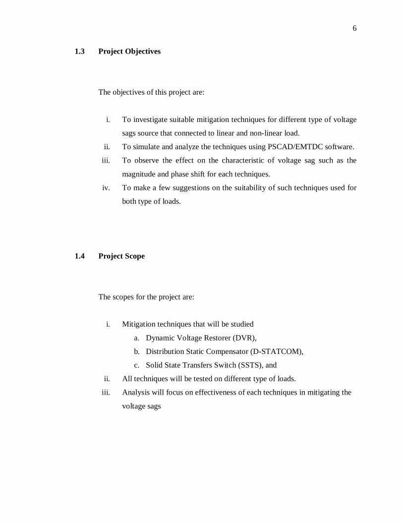
1.3 Project Objectives
The objectives of this project are:
i. To investigate suitable mitigation techniques for different type of voltage
sags source that connected to linear and non-linear load.
ii. To simulate and analyze the techniques using PSCAD/EMTDC software.
iii. To observe the effect on the characteristic of voltage sag such as the
magnitude and phase shift for each techniques.
iv. To make a few suggestions on the suitability of such techniques used for
both type of loads.
1.4 Project Scope
The scopes for the project are:
i. Mitigation techniques that will be studied
a. Dynamic Voltage Restorer (DVR),
b. Distribution Static Compensator (D-STATCOM),
c. Solid State Transfers Switch (SSTS), and
ii. All techniques will be tested on different type of loads.
iii. Analysis will focus on effectiveness of each techniques in mitigating the
voltage sags