Voltage Relay REU610REU610€¦ · The voltage relay REU610 is a versatile multifunction protection...
132
Voltage Relay REU610 REU610 Technical Reference Manual
Transcript of Voltage Relay REU610REU610€¦ · The voltage relay REU610 is a versatile multifunction protection...

Voltage RelayREU610REU610
Technical Reference Manual


3
Contents
Copyrights ................................................................................. 5
1. Introduction..............................................................71.1. This manual.............................................................. 71.2. Use of symbols ......................................................... 71.3. Intended audience ..................................................... 71.4. Product documentation ............................................... 81.5. Document conventions ............................................... 81.6. Document revisions.................................................... 9
2. Safety information................................................... 11
3. Product overview....................................................133.1. Use of the relay....................................................... 133.2. Features................................................................. 13
4. Application .............................................................154.1. Requirements.......................................................... 154.2. Configuration .......................................................... 15
5. Technical description ..............................................175.1. Functional description............................................... 17
5.1.1. Product functions ......................................... 175.1.1.1. Protection functions ....................... 175.1.1.2. Inputs .......................................... 175.1.1.3. Outputs........................................ 185.1.1.4. Disturbance recorder...................... 185.1.1.5. Front panel................................... 185.1.1.6. Non-volatile memory ...................... 195.1.1.7. Self-supervision............................. 195.1.1.8. Time synchronization ..................... 20
5.1.2. Measurements ............................................ 215.1.3. Configuration............................................... 225.1.4. Protection ................................................... 24
5.1.4.1. Block diagram............................... 245.1.4.2. Overvoltage protection ................... 245.1.4.3. Undervoltage protection.................. 265.1.4.4. Residual overvoltage protection ....... 295.1.4.5. Circuit-breaker failure protection....... 305.1.4.6. Inverse definite minimum time
characteristics............................... 305.1.4.7. Settings ....................................... 365.1.4.8. Technical data on protection
functions ...................................... 465.1.5. Trip-circuit supervision .................................. 47
Voltage Relay
Technical Reference Manual
REU610REU6101MRS755769
Issued: 31.01.2006Version: F/18.11.2011

5.1.6. Trip lockout function ..................................... 495.1.7. Trip counters for circuit-breaker condition
monitoring .................................................. 505.1.8. Indicator LEDs and operation indication
messages................................................... 505.1.9. Demand values ........................................... 515.1.10. Commissioning tests .................................... 515.1.11. Disturbance recorder .................................... 52
5.1.11.1. Function....................................... 525.1.11.2. Disturbance recorder data............... 525.1.11.3. Control and indication of
disturbance recorder status ............. 535.1.11.4. Triggering..................................... 535.1.11.5. Settings and unloading ................... 545.1.11.6. Event code of the disturbance
recorder ....................................... 545.1.12. Recorded data of the last events .................... 545.1.13. Communication ports.................................... 555.1.14. IEC 60870-5-103 remote communication
protocol...................................................... 575.1.15. Modbus remote communication protocol .......... 60
5.1.15.1. Profile of Modbus .......................... 615.1.16. DNP 3.0 remote communication protocol ......... 73
5.1.16.1. Protocol parameters....................... 735.1.16.2. DNP 3.0 point list .......................... 735.1.16.3. DNP 3.0 device profile ................... 765.1.16.4. Specific DNP features .................... 82
5.1.17. SPA bus communication protocol parameters ... 855.1.17.1. Event codes ................................. 98
5.1.18. Self-supervision (IRF) system .......................1025.1.19. Relay parameterization ................................104
5.2. Design description ..................................................1045.2.1. Input/output connections ..............................1045.2.2. Serial communication connections ................. 1105.2.3. Technical data ............................................ 116
6. Ordering information ............................................. 121
7. Check lists ........................................................... 123
8. Abbreviations ....................................................... 129
4
REU610REU610 Voltage Relay
Technical Reference Manual
1MRS755769

5
CopyrightsThe information in this document is subject to change without notice and should notbe construed as a commitment by ABB Oy. ABB Oy assumes no responsibility forany errors that may appear in this document.
In no event shall ABB Oy be liable for direct, indirect, special, incidental orconsequential damages of any nature or kind arising from the use of this document,nor shall ABB Oy be liable for incidental or consequential damages arising fromthe use of any software or hardware described in this document.
This document and parts thereof must not be reproduced or copied without writtenpermission from ABB Oy, and the contents thereof must not be imparted to a thirdparty nor used for any unauthorized purpose.
The software or hardware described in this document is furnished under a licenseand may be used, copied or disclosed only in accordance with the terms of suchlicense.
© Copyright 2011 ABB Oy
All rights reserved.
Trademarks
ABB is a registered trademark of ABB Group. All other brand or product namesmentioned in this document may be trademarks or registered trademarks of theirrespective holders.
Guarantee
Please inquire about the terms of guarantee from your nearest ABB representative.
Voltage Relay
Technical Reference Manual
REU610REU6101MRS755769

6

7
1. Introduction
1.1. This manual
This manual provides thorough information on the voltage relay REU610 and itsapplications, focusing on giving a technical description of the relay.
Refer to the Operator’s Manual for instructions on how to use the human-machineinterface (HMI) of the relay, also known as the man-machine interface (MMI), andto the Installation Manual for installation of the relay.
1.2. Use of symbols
This publication includes the following icons that point out safety-related conditionsor other important information:
The electrical warning icon indicates the presence of a hazard whichcould result in electrical shock.
The warning icon indicates the presence of a hazard which could resultin personal injury.
The caution icon indicates important information or warning related tothe concept discussed in the text. It might indicate the presence of ahazard which could result in corruption of software or damage toequipment or property.
The information icon alerts the reader to relevant facts and conditions.
The tip icon indicates advice on, for example, how to design yourproject or how to use a certain function.
Although warning hazards are related to personal injury, it should be understoodthat operation of damaged equipment could, under certain operational conditions,result in degraded process performance leading to personal injury or death.Therefore, comply fully with all warning and caution notices.
1.3. Intended audience
This manual is intended for operators and engineers to support normal use of aswell as configuration of the product.
Voltage Relay
Technical Reference Manual
REU610REU6101MRS755769

1.4. Product documentation
In addition to the relay and this manual, the delivery contains the following relay-specific documentation:
Table 1.4.-1 REU610 product documentation
Name Document ID
Certificate of verification 1MRS081662
Installation Manual 1MRS752265-MUM
Operator’s Manual 1MRS755770
Table 1.4.-2 Other reference documentation for REU610
Name Document ID
Modicon Modbus Protocol Reference Guide, Rev. E PI-MBUS-300
1.5. Document conventions
The following conventions are used for the presentation of material:
* Push button navigation in the human-machine interface (HMI) menu structure ispresented by using the push button icons, for example:
To navigate between the options, use and .
* HMI menu paths are presented as follows:
Use the arrow buttons to select CONFIGURATION\COMMUNICATION\SPASETTINGS\PASSWORD SPA.
* Parameter names, menu names, relay indication messages and relay's HMI viewsare shown in a Courier font, for example:
Use the arrow buttons to monitor other measured values in the menus DEMANDVALUES and HISTORY DATA.
* HMI messages are shown inside quotation marks when it is good to point outthem for the user, for example:
When you store a new password, the relay confirms the storage by flashing “- --” once on the display.
8
REU610REU610 Voltage Relay
Technical Reference Manual
1MRS755769

9
1.6. Document revisions
Version IEDRevision
Date History
A A 01.02.2006 Document created
B C 30.11.2006 Content updated
C C 01.10.2007 Content updated
D C 12.12.2007 Added information related to orderingparts and accessories.
E C 22.05.2009 Content updated
F C 18.11.2011 Language sets updated.
Voltage Relay
Technical Reference Manual
REU610REU6101MRS755769

10

11
2. Safety information
Dangerous voltages can occur on the connectors, even though theauxiliary voltage has been disconnected.
Non-observance can result in death, personal injury or substantialproperty damage.
Only a competent electrician is allowed to carry out the electricalinstallation.
National and local electrical safety regulations must always befollowed.
The frame of the device has to be carefully earthed.
When the plug-in unit has been detached from the case, do not touchthe inside of the case. The relay case internals may contain highvoltage potential and touching these may cause personal injury.
The device contains components which are sensitive to electrostaticdischarge. Unnecessary touching of electronic components musttherefore be avoided.
Breaking the sealing tape on the upper handle of the device will resultin loss of guarantee and proper operation will no longer be insured.
Voltage Relay
Technical Reference Manual
REU610REU6101MRS755769

12

13
3. Product overview
3.1. Use of the relay
The voltage relay REU610 is a versatile multifunction protection relay mainlydesigned for overvoltage and undervoltage protection and for supervision ofmedium voltage distribution networks. The relay can also be used for protectinggenerators, motors and transformers.
The relay is based on a microprocessor environment. A self-supervision systemcontinuously monitors the operation of the relay.
The HMI includes a liquid crystal display (LCD) which makes the local use of therelay safe and easy.
Local control of the relay via serial communication can be carried out with acomputer connected to the front communication port. Remote control can be carriedout via the rear connector connected to the control and monitoring system throughthe serial communication bus.
3.2. Features
* Overvoltage protection with definite-time or IDMT characteristic, low-set stage* Overvoltage protection with definite-time or IDMT characteristic, high-set stage
* Based on phase-to-phase voltage measurement or negative phase-sequence(NPS) voltage
* Undervoltage protection with definite-time or IDMT characteristic, low-set stage* Can also be used as alarm stage
* Undervoltage protection with definite-time or IDMT characteristic, high-setstage* Based on phase-to-phase voltage measurement or positive phase-sequence
(PPS) voltage* Residual overvoltage protection with definite-time characteristic, low-set stage* Residual overvoltage protection with definite-time characteristic, high-set stage* Circuit-breaker failure protection* Trip counters for circuit-breaker condition monitoring* Trip-circuit supervision with possibility to route the warning signal to a signal
output* Trip lockout function* Four accurate voltage inputs
* User-selectable rated voltage 100/110/115/120 V* User-selectable rated frequency 50/60 Hz* Three normally open power output contacts* Two change-over signal output contacts and three additional change-over signal
output contacts on the optional I/O module* Output contact functions freely configurable for wanted operation
Voltage Relay
Technical Reference Manual
REU610REU6101MRS755769

* Two galvanically isolated digital inputs and three additional galvanically isolateddigital inputs on the optional I/O module
* Disturbance recorder:* Recording time up to 80 seconds* Triggering by one or several internal or digital input signals* Records four analog channels and up to eight user-selectable digital channels* Adjustable sampling rate
* Non-volatile memory for:* Up to 100 event codes with time stamp* Setting values* Disturbance recorder data* Recorded data of the five last events with time stamp* Number of starts for protection stages* Operation indication messages and LEDs showing the status at the moment of
power failure* HMI with an alphanumeric LCD and navigation buttons
* Eight programmable LEDs* Multi-language support* User-selectable password protection for the HMI* Display of primary voltage values* All settings can be modified with a PC* Optical front communication connection: wirelessly or via cable* Optional rear communication module with plastic fibre-optic, combined fibre-
optic (plastic and glass) or RS-485 connection for system communication usingthe SPA-bus, IEC 60870-5-103 or Modbus (RTU and ASCII) communicationprotocol
* Optional DNP 3.0 rear communication module with RS-485 connection forsystem communication using the DNP 3.0 communication protocol
* Battery back-up for real-time clock* Time synchronization via a digital input* Battery charge supervision* Continuous self-supervision of electronics and software
* At an internal relay fault, all protection stages and outputs are locked* Detachable plug-in unit
14
REU610REU610 Voltage Relay
Technical Reference Manual
1MRS755769

15
4. ApplicationREU610 is a versatile multifunction voltage relay which is used in general voltagesupervision applications. It complements the range of feeder protection relayREF610 and motor protection relay REM610 in industrial outgoing feeder andmotor feeder applications. The relay can also be used as back-up protection forindustrial as well as utility applications.
The large number of integrated protection functions, including two-stageovervoltage protection, two-stage undervoltage protection and two-stage residualovervoltage protection, makes the relay a complete protection against variousvoltage fault conditions.
The large number of digital inputs and output contacts allows a wide range ofapplications.
4.1. Requirements
To secure correct and safe operation of the relay, preventive maintenance isrecommended to be performed every five years when the relay is operating underthe specified conditions; see Table 4.1.-1 and Section 5.2.3. Technical data.
When being used for real-time clock or recorded data functions, the battery shouldbe changed every five years.
Table 4.1.-1 Environmental conditions
Recommended temperature range (continuous) -10...+55°C
Limit temperature range (short-term) -40...+70°C
Temperature influence on the operation accuracy of the voltage relaywithin the specified service temperature range
0.1%/°C
Transport and storage temperature range -40...+85°C
4.2. Configuration
The appropriate configuration of the output contact matrix enables the use of thesignals from the protection stages as contact functions. The start signals can be usedfor blocking co-operating protection relays and signalling.
The Fig. 4.2.-1 represents the relay with trip lockout function and external resetswitch.
Voltage Relay
Technical Reference Manual
REU610REU6101MRS755769

� � � �� ��� �� ��
��
��
���
���
���
���
���
� � � � � �� ��
� �
� �
� �
� �
� �
��
���������
��
���������
��
���
� �
� �
� �
�
��
� � � � � �� ���
��
� � � � � �� ���
��
� � � � � �� ��
�
��
� � � � � �� ���
��
� � � � � �� ���
��
� � � � � �� ���
��
� � � � � �� ��
�
��
� �
� � � �� ��� �� ��
��
�� � �
� � � �� ��� �� �� ��
�� � �
� � � �� ��� �� �� ��
�� � �
� � � �� ��� �� ��
��
�� � �
����
���������������������������������������������
����
��
���
��
������������������������������������������������������������������������������������������������������������
����������������������
��
��
��
����
���������������������������������������
�������������������������������������������������
�� �� ��
���������������
�����
��
��
��
��
��
!
�"
#�#"
� �� �
� �� �
� �� �
� �� �
� �� �
� �� �
� �� �
� �� �
�
�$
%
%
&
&&
���
���
���������
���������
'$�
'$�
'$�
'$�
'$�
�()*+"�,
)�-)
.-*(
�,+/0*"1
)�-)
.-*(
�,+/0*"1
$"#*/�)*+"2�/,3�-3#
��)(�)�/+")�/)2��",�)/43#
536
+-*73#�8�,�32�/,3�-3#
3))*"1�1-+�(�23,3/)*+"
.*63�29"/
:�)3-"�,�.-*(
:�)3-"�,�)-*(
�,+/0*"1
�,+/0*"1
)�-)
.-*(
�,+/0*"1
)�-)
.-*(
:�)3-"�,�.-*113-*"1
323)
.-*(�,+/0+�)
�()*+"�,
:�)3-"�,�.-*113-*"1
.-*(
;�-"*"1
.-*(�,+/0+�)
3,<%2�(3-8*2*+"
$ �
�,+/0*"1
$ �
)�-)
.-*(
)�-)
.-*(
&
%
=���/)+-9�#3<��,)
=�:��6(,3�23))*"12
A051474_2
Fig. 4.2.-1 Connection diagram
16
REU610REU610 Voltage Relay
Technical Reference Manual
1MRS755769

17
5. Technical description
5.1. Functional description
5.1.1. Product functions
5.1.1.1. Protection functions
Table 5.1.1.1.-1 IEC symbols and IEEE device numbers
Function description IEC symbol IEEE devicenumber
Overvoltage protection, low-set stage U> 59P-1
Overvoltage protection, high-set stage U>> 59P-2
Negative phase-sequence overvoltage protection U2> 47
Undervoltage protection, low-set stage U< 27P-1
Undervoltage protection, high-set stage U<< 27P-2
Positive phase-sequence undervoltage protection U1< 27D
Residual overvoltage protection, low-set stage U0> 59N-1
Residual overvoltage protection, high-set stage U0>> 59N-2
Circuit-breaker failure protection CBFP CBFAIL
Lockout relay 86
For protection function descriptions, refer to Section 5.1.4. Protection.
5.1.1.2. Inputs
The relay is provided with four energizing inputs, two digital inputs and threeoptional digital inputs controlled by an external voltage. Three of the energizinginputs are for the phase-to-phase voltages and one for the residual voltage.
The relay is mainly designed to measure phase-to-phase voltages, but itcan be used for measuring phase-to-earth voltages as well. However,the relay does not convert the voltage from phase-to-earth voltage tophase-to-phase voltage.
The functions of the digital inputs are determined with the SGB switches. Fordetails, refer to Section 5.2.1. Input/output connections and Table 5.1.4.7.-7,Table 5.2.1.-1 and Table 5.2.1.-5.
Voltage Relay
Technical Reference Manual
REU610REU6101MRS755769

5.1.1.3. Outputs
The relay is provided with:
* Three power output contacts PO1, PO2 and PO3* Two signal output contacts SO1 and SO2* Three optional signal output contacts SO3, SO4 and SO5
Switchgroups SGR1...8 are used for routing internal signals from the protectionstages and the external trip signal to the wanted signal or power output contact. Theminimum pulse length can be configured to be 40 or 80 ms and the power outputcontacts can be configured to be latched.
5.1.1.4. Disturbance recorder
The relay includes an internal disturbance recorder which records the momentarymeasured values or the RMS curves of the measured signals, and up to eight user-selectable digital signals: the digital input signals and the internal signals from theprotection stages. Any digital signal can be set to trigger the recorder on either thefalling or rising edge.
5.1.1.5. Front panel
The front panel of the relay contains:
* Alphanumeric 2 × 16 characters’ LCD with backlight and automatic contrastcontrol
* Threeindicator LEDs (green, yellow, red) with fixed functionality* Eight programmable indicator LEDs (red)* HMI push-button section with four arrow buttons and buttons for clear/cancel
and enter, used in navigating in the menu structure and in adjusting setting values* Optically isolated serial communication port with an indicator LED.
There are two levels of HMI passwords; main HMI setting password for all settingsand HMI communication password for communication settings only.
The HMI passwords can be set to protect all user-changeable values from beingchanged by an unauthorized person. Both the HMI setting password and the HMIcommunication password remain inactive and are not required for altering parametervalues until the default HMI password is replaced.
Entering the HMI setting or communication password successfully canbe selected to generate an event code. This feature can be used toindicate interaction activities via the local HMI.
For further information on the HMI, refer to the Operator’s Manual.
18
REU610REU610 Voltage Relay
Technical Reference Manual
1MRS755769

19
5.1.1.6. Non-volatile memory
The relay can be configured to store various data in a non-volatile memory, whichretains its data also in case of loss of auxiliary voltage (provided that the battery hasbeen inserted and is charged). Operation indication messages and LEDs, disturbancerecorder data, event codes and recorded data can all be configured to be stored in thenon-volatile memory whereas setting values and trip counters are always stored inthe EEPROM. The EEPROM does not require battery backup.
5.1.1.7. Self-supervision
The self-supervision system of the relay manages run-time fault situations andinforms the user about an existing fault. There are two types of fault indications;internal relay fault (IRF) indications and warnings. Internal relay faults prevent relayoperation. Warnings are less severe faults and continued relay operation with full orreduced functionality is allowed.
Internal relay fault (IRF)
When the self-supervision system detects a permanent internal relay fault, the greenindicator LED starts to flash. At the same time, the IRF contact (also referred to asthe IRF relay), which is normally picked up, drops off. The text INTERNAL FAULTand a fault code appear on the display.
$!.: ! ��� ��.� ��.���':��>�
A040278
Fig. 5.1.1.7.-1 Permanent IRF
Warning
In case of a less severe fault (warning), the relay continues to operate except forthose protection functions possibly affected by the fault. At this type of fault, thegreen indicator LED remains lit as during normal operation, but the text WARNINGwith a fault code or a text message indicating the fault type appears on the LCD. Incase of a warning due to an external fault in the trip circuit detected by the trip-circuit supervision, SO2 is activated (if SGF1/8=1).
Voltage Relay
Technical Reference Manual
REU610REU6101MRS755769

; !$!�� ..: ?���;
A040279
Fig. 5.1.1.7.-2 Warning with text message
; !$!�� ��.���':>������
A040280
Fig. 5.1.1.7.-3 Warning with numeric code
For fault codes, refer to 5.1.18. Self-supervision (IRF) system
5.1.1.8. Time synchronization
Time synchronization of the relay’s real-time clock can be realized in two differentways: via serial communication using a communication protocol or via a digitalinput.
When time synchronization is realized via serial communication, the time is writtendirectly to the relay’s real-time clock.
Any digital input can be configured for time synchronization and used for eitherminute-pulse or second-pulse synchronization. The synchronization pulse isautomatically selected and depends on the time range within which the pulse occurs.Two detected pulses within acceptable time range are required before the relayactivates pulse synchronization. Respectively, if the synchronization pulsesdisappear, the relay takes time that corresponds to the time range of four pulsesbefore de-activating pulse synchronization. The time must be set once, either viaserial communication or manually via the HMI.
When the time is set via serial communication and minute-pulse synchronization isused, only year-month-day-hour-minute is written to the relay’s real-time clock, andwhen second-pulse synchronization is used, only year-month-day-hour-minute-second is written. The relay’s real-time clock will be rounded to the nearest wholesecond or minute, depending on whether second- or minute-pulse synchronization isused. When the time is set via the HMI, the entire time is written to the relay’s real-time clock.
20
REU610REU610 Voltage Relay
Technical Reference Manual
1MRS755769

21
If the synchronization pulse differs more than ±0.05 seconds for second-pulse or ±2seconds for minute-pulse synchronization from the relay’s real-time clock, thesynchronization pulse is rejected.
Time synchronization is always triggered on the rising edge of the digital inputsignal. The time is adjusted by accelerating or decelerating the relay's clock. By thisway the clock neither stops nor makes sudden jumps during the time adjustment.The typical accuracy achievable with time synchronization via a digital input is ±2.5milliseconds for second-pulse and ±5 milliseconds for minute-pulsesynchronization.
The pulse length of the digital input signal does not affect timesynchronization.
If time synchronization messages are received from a communicationprotocol as well, they have to be synchronized within ±0.5 minutes atminute-pulse or ±0.5 seconds at second-pulse synchronization.Otherwise the time difference may appear as rounding errors. If it ispossible that the synchronization messages from the communicationprotocol are delayed more than 0.5 seconds, minute-pulsesynchronization must be used.
When the minute-pulse synchronization is active and long time formatis sent via a communication protocol, the protocol's second andmillisecond part is ignored. The protocol's minute part is rounded tothe nearest minute. Short time format is ignored altogether.
When the second-pulse synchronization is active and long or short timeformat is sent via a communication protocol, the protocol's millisecondpart is ignored. The protocol's second-part is rounded to the nearestsecond.
5.1.2. Measurements
The table below presents the measured values which can be accessed through theHMI.
Table 5.1.2.-1 Measured values
Indicator Description
U12 Measured phase-to-phase voltage U12
U23 Measured phase-to-phase voltage U23
U31 Measured phase-to-phase voltage U31
U0 Measured residual voltage U0
U1s Positive phase-sequence voltage
U2s Negative phase-sequence voltage
Voltage Relay
Technical Reference Manual
REU610REU6101MRS755769

Indicator Description
Ū 1_min The average voltage of the three phase-to-phase voltages during one minute
Ū n_min The average voltage of the three phase-to-phase voltages during the specified time range
Max Ū The maximum of one-minute average voltage ofthe Ū n_min
Umax The maximum voltage of the three phase-to-phase voltages since the last reset (withtimestamp)
Umin The minimum voltage of the three phase-to-phase voltages since the last reset (withtimestamp)
5.1.3. Configuration
The Fig. 5.1.3.-1 illustrates how the internal and digital input signals can beconfigured to obtain the required protection functionality.
22
REU610REU610 Voltage Relay
Technical Reference Manual
1MRS755769

23
� � � �� �� ��
�� ��
��
�� �
�� �
�� �
�� �
�� �
����
�����������������������������������
�����
� � � � ��
��
����
����
����
����
����
���
���
���
����������������������������������������������������������������������������������������������������������
����������������������
��
���������
��
���������
��
��
�
����
����
���
���
����
���
����
��������������������������������������
�
��
� � � � ��
��� ��
� � � � ��
���
��
� � � � ��
��
� ��
� � � � ��
��
�
��
� � � � ��
���
��
� � � � �� ��
� ��
� � � � ��
���
��
� �
� � � �� ��
�� ��
��
�� � �
� � � �� ��
�� �� ��
�� � �
� � � �� ��
�� ��
��
�� � �
� � � �� �� ��
��
��
�� � �
� ��
���
���
��������
�
�
���
���
��� �
��
��
��
��
��
� �� �
� �� �
� �� �
� �� �
� �� �
� �� �
� �� �
� �� �
���������
���������
'$�
'$�
'$�
'$�
'$�
�()*+"�,
)�-)
.-*(
�,+/0*"1
)�-)
.-*(
�,+/0*"1
$"#*/�)*+"2�/,3�-3#
��)(�)�/+")�/)2��",�)/43#
536
+-*73#�8�,�32�/,3�-3#
3))*"1�1-+�(�23,3/)*+"
.*63�29"/
:�)3-"�,�.-*(
:�)3-"�,�)-*(
�,+/0*"1
�,+/0*"1
)�-)
.-*(
�,+/0*"1
)�-)
.-*(
:�)3-"�,�.-*113-*"1
323)
.-*(�,+/0+�)
�()*+"�,
:�)3-"�,�.-*113-*"1
.-*(
;�-"*"1
.-*(�,+/0+�)
3,<%2�(3-8*2*+"
$ �
�,+/0*"1
$ �
)�-)
.-*(
)�-)
.-*(
=���/)+-9�#3<��,)
A051475_2
Fig. 5.1.3.-1 Signal diagram
Voltage Relay
Technical Reference Manual
REU610REU6101MRS755769

The functions of the relay are selected with the switches of switchgroups SGF, SGB,SGR and SGL. The checksums of the switchgroups are found under SETTINGS inthe HMI menu. The functions of the switches are explained in detail in thecorresponding SG_ tables.
5.1.4. Protection
5.1.4.1. Block diagram
��������������������������������
���������
�� �����
�
��������
���������
����������
����
���������
�
�+
�+
�+� �+��
��
��
���������
���������
!���
!�
��
�� !�"##"$%&���'
�(')*�$"+,&��&, �-&�.��"+"% !�/�*0�) ���-(!()"%�,1"++&%'2
31&�-"'1&-�%(+&�(+-(,")&'� 0)( +"%�4*+,)( +"%()5�
�2��%&"��(+-(,")( +' $5�)1&�-(!()"%�(+0*)�'(!+"%�2��%&"��(+-(,")( +'�"+-�*+%"),1� *)0*)�, +)",)' $5�)1&����-(!()"%�(+0*)�'(!+"%�2��&'&)�(+-(,")( +'�"+-�#&# �(6&- 7"%*&'8 *+%"),1� *)0*)����, +)",)' $5�)1&�-(!()"%�(+0*)�'(!+"%
�0)( +"%�-(!()"%(+0*)'
.9���# -*%&2
�(!()"%�(+0*)' �9��9��9��9��9�
�:(),1!� *0' 4 �-(!()"%�(+0*)' �� )&,)( +��&%"5�4*+,)( +'
;+"% !�(+0*)'
�:(),1!� *0' 4 �0� !�"##"$%&����'
���)�-)���.-*(������� )�-)������� .-*(���)�-)���.-*(������� )�-)������� .-*(�� )�-)�� .-*(��� )�-)��� .-*(
���.-*(������� .-*(���.-*(������� .-*(�� .-*(��� .-*(.-*(�,+/0+�)'$�'$�'$�'$�'$�
323)�� �@
323)�� �@
323)�� �@
3))*"1�1-+�(.*63�29"/:�) .-*(:�) .-*1�����:�) .-*1�.-*(�,+/0+�).-*(�,+/0+�)�-323)�,+/0����,+/0���������,+/0����,+/0���������,+/0 ���,+/0 ���
'$�'$�'$�'$�'$�
)�-).-*(
���:�.�. $� ���
�,+/0)�-).-*(
�,+/0
�,+/0)�-).-*(
�,+/0
�,+/0)�-).-*(
.-*(�,+/0+�)
.-*(�,+/0+�)
:�) .-*1 323)���
�,+/0
)�-).-*(
)�-).-*(
�����.-*(' �.-*113-3#
A�'
������������������������
��������
�(!()"%� *)0*)'.�*)0*)�, +)",)'2
9���9<�9�;39�<�3;�3�;�;�=�9<�9�;39�<3�9��9<�9�;39�<
9���(+-(,")( +�����.!�&&+2�)"�)�;%"�#�.5&%% :2�"+-)�(0�.�&-2�(+-(,")( +����'
���)�-)���.-*(������� )�-)������� .-*(���)�-)���.-*(������� )�-)������� .-*(�� )�-)�� .-*(��� )�-)��� .-*(�>) 3� (0
�:(),1!� *0' 4 � *)0*)�, +)",)'
3� (0�% ,? *)
�()*+"�,�#*1*)�,+�)(�)2
B$���6+#�,3@
@"�+(+!
$ �
A051476_2
Fig. 5.1.4.1.-1 Block diagram
5.1.4.2. Overvoltage protection
The overvoltage protection can be based on either conventional voltagemeasurement or calculated negative phase-sequence voltage.
The low-set overvoltage stage U> is based on conventional voltage measurement.
The high-set overvoltage stage U>> can be set to be based on either
* Conventional voltage measurement (U>> mode selected), or* Calculated negative phase-sequence voltage (U2> mode selected).
24
REU610REU610 Voltage Relay
Technical Reference Manual
1MRS755769

25
The selection between these modes is made either by using HMI or parameter S7,the default setting being conventional measurement. Stage U1< (PPS) and U2>(NPS) cannot be used at the same time.
Stage U>> can be set out of operation in SGF3/1. This state is indicated by dasheson the LCD and by “999” when the set start value is read via serial communication.
It is possible to block the tripping of an overvoltage stage by applyinga digital input signal to the relay.
Overvoltage protection based on conventional voltagemeasurement
Both the low-set and the high-set overvoltage stage can independently be set to startand trip when one of the three voltages or all the voltages rise above the set startvalue. By default, both stages operate when one of the three voltages rise above theset start value. The selection is made in SGF4/5 and SGF4/6.
When the phase-to-phase voltage values exceed the set start value of the low-setstage, U>, the stage generates a start signal after a ~ 60 ms’ start time. When the setoperate time at definite-time characteristic or the calculated operate time at IDMTcharacteristic elapses, the stage generates a trip signal.
Stage U> has a settable resetting time (both at definite-time and IDMTcharacteristics), tr>, for reset coordination with existing electromechanical relays orfor reducing fault clearance times of recurring, transient faults. If stage U> hasstarted and the phase-to-phase voltages fall below the set start value of the stage, thestart of the stage remains active for the set resetting time. If the phase-to-phasevoltages exceed the set start value again while the timer is running, the timer iscleared and the start of the stage remains active.
Consequently, the set resetting time ensures that when the stage starts because ofvoltage spikes, it is not immediately reset. If stage U> has already tripped, the stageis reset in 70 ms after the phase-to-phase voltages have fallen below 0.5 times the setstart value of the stage. However, if stage U> has already tripped and the phase-to-phase voltages have fallen below the set start value of the stage, but not below 0.5times the set start value, the stage is reset when the set resetting time is expired.
When the conventional protection mode is selected and the phase-to-phase voltagesexceed the set start value of the high-set stage, U>>, the stage generates a startsignal after a ~ 50 ms’ start time. When the set operate time at definite-timecharacteristic or the calculated operate time at IDMT characteristic elapses, the stagegenerates a trip signal. The stage is reset in 70 ms after the phase-to-phase voltageshave fallen below the set start value of the stage.
The conventional overvoltage stages have a settable drop-off/pick-up ratio, which isadjustable between 0.95...0.99, the default being 0.97.
Voltage Relay
Technical Reference Manual
REU610REU6101MRS755769

The settable drop-off/pick-up ratio enables the voltage protection tosatisfactorily work with a voltage regulator, for instance, such as a tapchanger. The tap changer step is often 1.67%, which is less than thedrop-off/pick-up ratio of voltage relays. This can cause a situationwhere the voltage protection remains active even though the tapchanger already has changed the voltage.
Overvoltage protection based on negative phase-sequencevoltage
When the calculated negative phase-sequence voltage value U2s exceeds the set startvalue of the stage U2>, the stage generates a start signal after a 50 ms' start time.When the set operate time at definite-time characteristics or the calculated operatetime at IDMT characteristics elapses, the stage generates a trip signal. The stage isreset in 70 ms after the calculated negative phase-sequence voltage value has fallenbelow the set start value of the stage.
The negative phase-sequence voltage is calculated as follows:
U2s = + × + ×U a U a U122
23 31
3(1)
a = 1∠ 120°a2 = 1∠ -120°
The negative phase-sequence value is scaled to the amplitude of the measuredvoltage. On a network with a reverse phase order, the calculated negative phase-sequence value has the same amplitude as the measured voltage signal.
Stage U2> can be set to be blocked when one of the measured phase-to-phasevoltages falls below 0.15 × Un. The selection is made in SGF4.
Stage U2> has a fixed drop-off/pick-up ratio of 0.96.
5.1.4.3. Undervoltage protection
The undervoltage protection can be based on either conventional voltagemeasurement or the calculated positive phase-sequence voltage.
The low-set undervoltage stage U< is based on conventional voltage measurement.The low-set stage can also be used for alarm purposes.
The high-set undervoltage stage U<< can be set to be based on either:
* Conventional voltage measurement (U<< mode selected) or* Calculated positive phase-sequence voltage (U1< mode selected).
26
REU610REU610 Voltage Relay
Technical Reference Manual
1MRS755769

27
The selection between these modes is made either by using HMI or parameter S7,the default setting being conventional measurement. Stage U1< (PPS) and U2>(NPS) cannot be used at the same time.
The undervoltage stages can be set to be blocked when one of the measured voltagesfall below 0.15 × Un. The blocked stage is reset after the set resetting time. Thisfeature can be used to avoid unnecessary starts and trips during, for example, anauto-reclose sequence. In addition, the tripping of stage U< can be set to be blockedby the stage U<< start. The selection is made in SGF4.
Stage U<< can be set out of operation in SGF3/2. This state is indicated by dasheson the LCD and by 999 when the set start value is read via serial communication.
It is possible to block the tripping of an undervoltage stage by applyinga digital input signal to the relay.
Undervoltage protection based on conventional voltagemeasurement
Both the low-set and the high-set undervoltage stage can independently be set tostart and trip when one of the three voltages or all the voltages fall below the set startvalue. By default, the low-set undervoltage stage operates when one of the threevoltages fall below the set start value and the high-set undervoltage stage operateswhen all the voltages fall below the set start value. The selection is made in SGF4/7and SGF4/8.
When the phase-to-phase voltage values fall below the set start value of the low-setstage, U<, the stage generates a start signal after a ~ 80 ms’ start time. When the setoperate time at definite-time characteristic or the calculated operate time at IDMTcharacteristic elapses, the stage generates a trip signal.
Stage U< has a settable resetting time (both at definite-time and IDMTcharacteristics), tr<, for reset coordination with existing electromechanical relays orfor reducing fault clearance times of recurring, transient faults. If stage U< hasstarted and the phase-to-phase voltages exceed the set start value of the stage, thestart of the stage remains active for the set resetting time. If the phase-to-phasevoltages fall below the set start value again while the timer is running, the timer iscleared and the start of the stage remains active.
Consequently, the set resetting time ensures that when the stage starts because ofvoltage drops, it is not immediately reset. If stage U< has already tripped, the stageis reset in 70 ms after the phase-to-phase voltages have fallen below 0.15 × Un.However, if stage U< has already tripped and the phase-to-phase voltages haveexceeded the set start value of the stage, the stage is reset when the set resetting timehas expired.
Stage U< tripping can be set to be blocked by the start of stage U<< or U1<.
Voltage Relay
Technical Reference Manual
REU610REU6101MRS755769

Stage U< can also be configured to be used for alarm purposes. When a trip signal isgenerated for alarm purposes, the Start/Alarm indicator LED is lit and the fault isindicated as an alarm instead of a trip.
When stage U< is configured to be used for alarm purposes:
* Start signal of stage is not generated* Trip signal of stage is generated, but it is indicated as an alarm* Stage cannot be used for triggering CBFP* Number of starts is increased instead of number of trips
When the conventional protection mode is selected and the voltages fall below theset start value of the high-set stage, U<<, the stage generates a start signal after a ~50 ms’ start time. When the set operate time at definite-time characteristic or thecalculated operate time at IDMT characteristic elapses, the stage generates a tripsignal. The stage is reset in 70 ms after the phase-to-phase voltages have exceededthe set start value of the stage.
The undervoltage stages have a settable drop-off/pick-up ratio, which is adjustablebetween 1.01...1.05, the default being 1.03.
Undervoltage protection based on positive phase-sequencevoltage
The undervoltage protection based on calculated positive phase-sequence voltagecan be applied to disconnecting a smaller power plant from the outside network, forinstance in situations where there is a fault in the network which can be critical forthe power plant, such as a short circuit either at the transmission or distributionnetwork level.
A situation of this kind can be critical for different reasons. The power plant can beleft to feed an isolated network due to a trip caused by a fault. In this case, there is arisk that the isolated network, which is in asynchronous state compared to the rest ofthe network, is reconnected to the network as a result of an autoreclosure, forinstance. In addition, the power plant can also fall into an asynchronous state in afault situation. These critical situations can be prevented by disconnecting the powerplant from the network fast enough by tripping the connecting circuit breaker.
The benefit of this function is that the voltage value measured during or after anetwork fault is a good measure of how critical the fault is for a smaller power plant.When the positive phase-sequence voltage value falls below the critical limit, thepower plant has to be disconnected from the network.
REU610 measuring the positive phase-sequence voltage complements othermethods used to disconnect smaller power plants. The application of these methodsis based on frequency and voltage measurement. The undervoltage protection basedon calculated positive phase-sequence voltage requires that the relay is in three-phase use.
28
REU610REU610 Voltage Relay
Technical Reference Manual
1MRS755769

29
When the calculated positive phase-sequence voltage value U1s falls below the setstart value of the stage U1<, the stage generates a start signal after a ~ 50 ms’ starttime. When the set operate time at definite-time characteristic or the calculatedoperate time at IDMT characteristic elapses, the stage generates a trip signal. Thestage is reset in 70 ms after the calculated positive phase-sequence voltage value hasexceeded the set start value of the stage.
The positive phase-sequence voltage is calculated as follows:
U1s = + × + ×U a U a U12 232
31
3(2)
a = 1∠ 120°a2 = 1∠ -120°
On a symmetrical network, this formula scales the positive phase-sequence value tothe same amplitude as the measured voltage signal.
Stage U<< can be set to be blocked when the measured voltage values fall below0.15 × Un. In addition, the tripping of stage U< can be set to be blocked by stageU<< start. The selection is made in SGF4.
Stage U1< has a fixed drop-off/pick-up ratio of 1.04.
5.1.4.4. Residual overvoltage protection
The residual overvoltage protection detects residual voltages caused by earth faults.
When the residual voltage exceeds the set start value of the low-set stage U0>, thestage generates a start signal after a ~ 70 ms’ start time. When the set operate timeelapses, the stage generates a trip signal.
Stage U0> has a settable resetting time t0r> for reset coordination with existingelectromechanical relays or for reducing fault clearance times of recurring, transientfaults. If stage U0> has started and the residual voltage falls below the set start valueof the stage, the start of the stage remains active for the set resetting time. If theresidual voltage exceeds the set start value again while the timer is running, thetimer is cleared and the start of the stage remains active.
Consequently, the set resetting time ensures that when the stage starts because ofvoltage spikes, it is not immediately reset. If stage U0> has already tripped, the stageis reset in 50 ms after the residual voltage falls below 0.5 times the set start value ofthe stage. However, if stage U0> has already tripped and the residual voltage hasfallen below the set start value of the stage, but not below 0.5 times the set startvalue, the stage is reset after the set resetting time (t0r>) has expired.
When the residual voltage exceeds the set start value of the high-set stage U0>>, thestage generates a start signal after a ~ 60 ms’ start time. When the set operate timehas elapsed, the stage generates a trip signal.
Voltage Relay
Technical Reference Manual
REU610REU6101MRS755769

If stage U0>> has started and the residual voltage falls below the set start value ofthe stage, the start of the stage remains active for 100 ms. If the residual voltageexceeds the set start value again while the timer is running, the timer is cleared andthe start of the stage remains active. If stage U0>> has already tripped, the stage isreset in 50 ms after the residual voltage falls below 0.5 times the set start value ofthe stage. However, if stage U0>> has already tripped and the residual voltage hasfallen below the set start value of the stage, but not below 0.5 times the set startvalue, the stage is reset after the 100 ms’ resetting time has expired.
Stage U0> can be set out of operation in SGF3/3 and stage U0>> can be set out ofoperation in SGF3/4. This state is indicated by dashes on the LCD and by 999when the set start value is read via serial communication.
It is possible to block the tripping of a residual overvoltage stage byapplying a digital input signal to the relay.
5.1.4.5. Circuit-breaker failure protection
The circuit-breaker failure protection (CBFP) detects situations where the tripremains active although the circuit breaker should have operated.
The CBFP unit generates a trip signal via output PO2 when the set operate time ofCBFP expires.
The CBFP can be triggered internally via protection functions. All the signals,except external trip, routed to output PO1 trigger the CBFP. If the fault situation isnot cleared when the set operate time has elapsed, the CBFP generates a trip signalvia output PO2.
The CBFP can also be selected to be triggered externally by applying a digital inputsignal to the relay, if the maximum of all three phase-to-phase voltages is above 0.15× Un. If the fault situation is not cleared when the set operate time has elapsed, theCBFP generates a trip signal via output PO2.
Internal triggering is selected by activating the CBFP in SGF1/6 and externaltriggering by activating the CBFP in SGB1...5/7.
Normally, the CBFP controls the upstream circuit breaker. However, it can also beused for tripping via redundant trip circuits of the same circuit breaker.
5.1.4.6. Inverse definite minimum time characteristics
Each of the overvoltage and undervoltage stages can be given either a definite-timeor an inverse definite minimum time (IDMT) characteristic. The following settingparameters determine the operation mode of the overvoltage and undervoltageprotection stages:
30
REU610REU610 Voltage Relay
Technical Reference Manual
1MRS755769

31
Table 5.1.4.6.-1 Operation mode setting parameters
Protectionstage
Parameter Setting
U> S3 0 = definite time1 = curve A2 = curve B
U>>/U2> S11 0 = definite time1 = curve A2 = curve B
U< S15 0 = definite time1 = curve C
U<</U1< S22 0 = definite time1 = curve C
At IDMT characteristic, the operate time of the stage is dependent on the voltagevalue: the greater the deviation from the setting value, the shorter the operate time.Three time/voltage curve groups are available: A, B and C.
An overvoltage stage starts when the measured voltage exceeds the setting value ofthe stage. An undervoltage stage starts when the measured voltage drops below thesetting value of the stage. However, the IDMT calculation does not start until thedeviation between the measured voltage and the setting value exceeds 3 percent.The operate time accuracy stated in technical data applies when the deviation is 10percent or higher.
Characteristics of the overvoltage stages
The IDMT characteristic curve groups A and B are designed for overvoltage stagesU> and U>>/U2>. Stages U> and U>>/U2> can be configured to use differentcharacteristics. The relationship between time and voltage at IDMT characteristiccan be expressed as follows:
t[s]=k 480
32 U U>
U>0.5
+ 0.05p
×
×⎛⎝⎜
⎞⎠⎟
− − (3)
t = operate timek = time multiplier k> or k>>U = measured voltageU> = set start value U> or U>>/U2>p = constant (see Table 5.1.4.6.-2)
The A- and B-type characteristics are illustrated in Fig. 5.1.4.6.-1 and Fig. 5.1.4.6.-2.
If the ratio between the voltage and the set value is higher than 1.6, theoperate time is the same as when the ratio is 1.6.
Voltage Relay
Technical Reference Manual
REU610REU6101MRS755769

Characteristic of the undervoltage stages
The IDMT characteristic curve group C is designed for undervoltage stages U< andU<</U1<. Stages U< and U<</U1< can be configured to use differentcharacteristics. The relationship between time and voltage at IDMT characteristiccan be expressed as follows:
t[s]=k 480
32 U< U
U<0.5
p
×
×⎛⎝⎜
⎞⎠⎟
− − (4)
t = operate timek = time multiplier k< or k<<U = measured voltageU< = set start value U< or U<</U1<p = constant (see Table 5.1.4.6.-2)
The C-type characteristic is illustrated in Fig. 5.1.4.6.-3.
If the ratio between the voltage and the set value is lower than 0.3, theoperate time is the same as when the ratio is 0.3.
Table 5.1.4.6.-2 Values of constant p
Time/voltagecharacteristic
A B C
p 2 3 2
32
REU610REU610 Voltage Relay
Technical Reference Manual
1MRS755769

33
�
�
�
�
��
��
� ��� ��� ��� ��� ��� ���
0�A0��
��
���
��
��
��
��
��
����A�����A��2����
)�2
A052084
Fig. 5.1.4.6.-1 Characteristics of type A
Voltage Relay
Technical Reference Manual
REU610REU6101MRS755769

�
�
�
�
��
��
� ��� ��� ��� ��� ��� �������A�����A��2����
0�A0��
���������������
)�2
A052086
Fig. 5.1.4.6.-2 Characteristics of type B
34
REU610REU610 Voltage Relay
Technical Reference Manual
1MRS755769

35
0�A0��
��
���
��
��
��
��
��
�������������������A�����A��2����
�
�
�
�
��
��
)�2
A052088
Fig. 5.1.4.6.-3 Characteristics of type C
Voltage Relay
Technical Reference Manual
REU610REU6101MRS755769

5.1.4.7. Settings
There are two alternative setting groups available, setting groups 1 and 2. Either ofthese setting groups can be used as the actual settings, one at a time. Both groupshave their related registers. By switching between the setting groups, a whole groupof settings can be changed at the same time. This can be done in any of thefollowing ways:
* Via the HMI* Entering SPA parameter V150 via serial communication* Via a digital input
Switching between setting groups via a digital input has a higherpriority than via the HMI or with the parameter V150.
The setting values can be altered via the HMI or with a PC provided with RelaySetting Tool.
Before the relay is connected to a system it must be assured that the relay has beengiven the correct settings. If there is any doubt, the setting values should be readwith the relay trip circuits disconnected or tested with current injection; refer toChapter 7. Check lists for additional information.
Table 5.1.4.7.-1 Setting values
Setting Description Setting range Default setting
U> Start value of stage U> 0.60…1.40 × Un 1.2
t> Operate time of stage U> 0.06…600 s 0.06
IDMT U> IDMT operation mode setting for U> 0 = definite time1 = curve A2 = curve B
0
k> IDMT time multiplier, k> 0.05…2.00 0.05
tr> Resetting time of stage U> 0.07...60.0 s 0.07
D/P> Drop-off/pick-up ratio of stage U> 0.95…0.99 0.97
U1s/U2s Mode U1s/U2s mode setting of stages U>> and U<< 0 = U>> and U<<1 = U>> and U1<2 = U2> and U<<
0
U>> Start value of stage U>> 0.80…1.60 × Un 1.2
U2> Start value of stage U2> 0.05…1.00 × Un 0.05
t>> Operate time of stage U>> 0.05…600 s 0.05
IDMT U>>/U2s IDMT operation mode setting for U>>/U2s 0 = definite time1 = curve A2 = curve B
0
k>> IDMT time multiplier, k>> 0.05…2.00 0.05
U< Start value of stage U< 0.20…1.20 × Un 0.2
t< Operate time of stage U< 0.10…600 s 0.1
IDMT U< IDMT operation mode setting for U< 0 = definite time1 = curve C
0
k< IDMT time multiplier, k< 0.10…2.00 0.1
36
REU610REU610 Voltage Relay
Technical Reference Manual
1MRS755769

37
Setting Description Setting range Default setting
tr< Resetting time of stage U< 0.07...60.0 s 0.07
D/P< Drop-off/pick-up ratio of stage U< 1.01…1.05 1.03
U<< Start value of stage U<< 0.20…1.20 × Un 0.2
U1< Start value of stage U1< 0.20…1.20 × Un 0.3
t<< Operate time of stage U<< 0.10…600 s 0.1
IDMT U<</U1s IDMT operation mode setting for U<</U1s 0 = definite time1 = curve C
0
k<< IDMT time multiplier, k<< 0.10…2.00 0.1
U0> Start value of stage U0> 2.0…80.0% Un 2.0
t0> Operate time of stage U0> 0.10…600 s 0.1
t0r> Resetting time of stage U0> 0.07...60.0 s 0.07
U0>> Start value of stage U0>> 2.0…80.0% Un 2.0
t0>> Operate time of stage U0>> 0.10…600 s 0.1
CBFP Operate time of CBFP 0.10…60.0 s 0.10
Switchgroups and parameter masks
The settings can be altered and the functions of the relay selected in the SG_ selectorswitchgroups. The switchgroups are software based and thus not physical switchesto be found in the hardware of the relay.
A checksum is used for verifying that the switches have been properly set. TheFig. 5.1.4.7.-1 shows an example of manual checksum calculation.
Voltage Relay
Technical Reference Manual
REU610REU6101MRS755769

������C � =
�����������������������
=======================�
�
�
�
�
�
�
�
�
�
�
�
�����������������������������������
����������������������������������������������������������������������������������
���������
���
���
���
�����
�����
������
������
������
D*)/4"�6E3-
�+2*)*+" ;3*14)*"1<�/)+-
F�,�3
/43/02�6
A051892
Fig. 5.1.4.7.-1 Example of calculating the checksum of a SG_ selector switchgroup
When the checksum, calculated according to the example above, equals thechecksum of the switchgroup, the switches in the switchgroup are properly set.
The factory default settings of the switches and the corresponding checksums arepresented in the following tables.
SGF1...SGF5
Switchgroups SGF1...SGF5 are used for configuring the wanted function asfollows:
38
REU610REU610 Voltage Relay
Technical Reference Manual
1MRS755769

39
Table 5.1.4.7.-2 SGF1
Switch Function Default setting
SGF1/1 Selection of the latching feature for PO1 0
SGF1/2 Selection of the latching feature for PO2 0
SGF1/3 Selection of the latching feature for PO3* When the switch is in position 0 and the measuring signal which caused the trip falls belowthe set start value, the output contact returns to its initial state.
* When the switch is in position 1, the output contact remains active although the measuringsignal which caused the trip falls below the set start value.
A latched output contact can be unlatched either via the HMI, a digital input or the serial bus.
0
SGF1/4 Minimum pulse length for SO1 and SO2 and optional SO3, SO4 and SO5* 0 = 80 ms* 1 = 40 ms
0
SGF1/5 Minimum pulse length for PO1, PO2 and PO3* 0 = 80 ms* 1 = 40 ms
The latching feature being selected for PO1, PO2 and PO3 overrides thisfunction.
0
SGF1/6 CBFP* 0 = CBFP is not in use* 1 = the signal to PO1 starts a timer which generates a delayed signal to PO2, provided thatthe fault is not cleared before the CBFP operate time has elapsed
0
SGF1/7 Trip lockout function* 0 = the trip lockout function is not in use. PO3 works as a normal power output relay.* 1 = the trip lockout function is in use. PO3 is dedicated to this function.
0
SGF1/8 External fault warning* When the switch is in position 1, the warning signal from the trip-circuit supervision is routedto SO2.
0
ΣSGF1 0
Table 5.1.4.7.-3 SGF2
Switch Function Default setting
SGF2/1 Operation mode of the start indication of stage U>a) 0
SGF2/2 Operation mode of the trip indication of stage U> 1
SGF2/3 Operation mode of the start indication of stage U>> or U2>a) 0
SGF2/4 Operation mode of the trip indication of stage U>> or U2> 1
SGF2/5 Operation mode of the start indication of stage U<a) 0
SGF2/6 Operation mode of the trip indication of stage U< 1SGF2/7 Operation mode of the start indication of stage U<< or U1<
a) 0
SGF2/8 Operation mode of the trip indication of stage U<< or U1< 1
SGF2/9 Operation mode of the start indication of stage U0>a) 0
SGF2/10 Operation mode of the trip indication of stage U0> 1
SGF2/11 Operation mode of the start indication of stage U0>>a) 0
SGF2/12 Operation mode of the trip indication of stage U0>>* 0 = the trip indication is automatically cleared after the fault has disappeared.* 1 = latching. The trip indication remains active although the fault has disappeared.
1
ΣSGF2 2730
Voltage Relay
Technical Reference Manual
REU610REU6101MRS755769

Switch Function Default settinga) When the switch is on, the phase(s) that caused the start are shown on LCD.
Table 5.1.4.7.-4 SGF3
Switch Function Default setting
SGF3/1 Inhibition of stage U>> or U2> 0
SGF3/2 Inhibition of stage U<< or U1< 0
SGF3/3 Inhibition of stage U0> 0
SGF3/4 U0>>* When the switch is in position 1, the stage is inhibited.
0
ΣSGF3 0
Table 5.1.4.7.-5 SGF4
Switch Function Default setting
SGF4/1 Selecting single-phase or three-phase use* 0 = three-phase use* 1 = single-phase use a)
When single-phase use is selected, the measured voltage has to be connectedto inputs X2.1-1 and X2.1-2. Additionally, the U1s/U2s mode setting S7 isoverridden and the negative phase-sequence protection mode and positivephase-sequence protection mode are not in use.
0
SGF4/2 Internal blocking of start and trip of stage U< when one of the measured phase-to-phasevoltages fall below 0.15 ×Un* 0 = internal blocking of start and trip of stage U<* 1 = no internal blocking of start and trip of stage U<
0
SGF4/3 Internal blocking of start and trip of stage U<< or U1< when one of the measured phase-to-phase voltages falls below 0.15 × Un* 0 = internal blocking of start and trip of stage U<< or U1<* 1 = no internal blocking of start and trip of stage U<< or U1<
0
SGF4/4 Blocking of stage U< tripping by the start of stage U<< or U1<* 0 = tripping of stage U< is not blocked* 1 = tripping of stage U< is blocked
0
SGF4/5 Start and trip criteria for stage U>a)
* 0 = stage operates when one of the phase-to-phase voltages rise above the set start value.* 1 = stage operates when all the phase-to-phase voltages rise above the set start value
0
SGF4/6 Start and trip criteria for stage U>>a)
* 0 = stage operates when one of the phase-to-phase voltages rise above the set start value.* 1 = stage operates when all the phase-to-phase voltages rise above the set start value.
This switch has no effect if the stage U>> is based on negative phase-sequencecalculation.
0
SGF4/7 Start and trip criteria for stage U<a)
* 0 = stage operates when one of the phase-to-phase voltages falls below the set start value.* 1 = stage operates when all the phase-to-phase voltages fall below the set value.
0
40
REU610REU610 Voltage Relay
Technical Reference Manual
1MRS755769

41
Switch Function Default setting
SGF4/8 Start and trip criteria for stage U<<a)
* 0 = stage operates when one of the phase-to-phase voltages falls below the set start value.* 1 = stage operates when all the phase-to-phase voltages fall below the set value.
This switch has no effect if stage U<< is based on positive-phase-sequencecalculation.
1
SGF4/9 U< Alarm mode selection* 0 = normal operation of stage U<, used for tripping purposes* 1 = stage U< operates as U< Alarm.
The alarm signal is routed to stage U< trip in relay matrix, and the start signal of stage U< isinhibited. When the alarm signal is active, the start LED is lit.
0
SGF4/10 Internal blocking of start and trip of stage U2> when one of the measured phase-to-phasevoltages falls below 0.15 × Un.* 0 = internal blocking of start and trip of stage U2>* 1 = no internal blocking of start and trip of stage U2>
0
ΣSGF4 128a) If the switch SGF4/1 is set to 1, the switches SGF4/5...8 are overridden. Thereby all the stages use only phase U12 as input, and other phasesare not checked or used.
Table 5.1.4.7.-6 SGF5
Switch Function Default setting
SGF5/1 Selection of the latching feature for programmable LED1 0
SGF5/2 Selection of the latching feature for programmable LED2 0
SGF5/3 Selection of the latching feature for programmable LED3 0
SGF5/4 Selection of the latching feature for programmable LED4 0
SGF5/5 Selection of the latching feature for programmable LED5 0
SGF5/6 Selection of the latching feature for programmable LED6 0
SGF5/7 Selection of the latching feature for programmable LED7 0SGF5/8 Selection of the latching feature for programmable LED8
* When the switch is in position 0 and the signal routed to the LED is reset, the programmableLED is cleared.
* When the switch is in position 1, the programmable LED remains lit although the signalrouted to the LED is reset.
A latched programmable LED can be cleared either via the HMI, a digital input or the serial bus.
0
ΣSGF5 0
SGB1...SGB5
The DI1 signal is routed to the functions below with the switches of switchgroupSGB1, the DI2 signal with those of SGB2, and so forth.
Voltage Relay
Technical Reference Manual
REU610REU6101MRS755769

Table 5.1.4.7.-7 SGB1...SGB5
Switch Function Default setting
SGB1...5/1 * 0 = indications are not cleared by the digital input signal* 1 = indications are cleared by the digital input signal
0
SGB1...5/2 * 0 = indications are not cleared and latched output contacts are not unlatched by the digitalinput signal
* 1 = indications are cleared and latched output contacts are unlatched by the digital inputsignal
0
SGB1...5/3 * 0 = indications and memorized values are not cleared and latched output contacts are notunlatched by the digital input signal
* 1 = indications and memorized values are cleared and latched output contacts are unlatchedby the digital input signal
0
SGB1...5/4 Switching between setting groups 1 and 2 by using the digital input* 0 = the setting group cannot be changed using the digital input* 1 = the setting group is changed by using the digital input. When the digital input is energized,setting group 2 is activated, if not, setting group 1 is activated.
When SGB1...5/4 is set to 1, it is important that the switch has the same settingin both setting groups.
0
SGB1...5/5 Time synchronization by the digital input signal 0
SGB1...5/6 External tripping by the digital input signal 0
SGB1...5/7 External triggering of the CBFP by the digital input signal 0
SGB1...5/8 External triggering of the trip lockout by the digital input signal 0
SGB1...5/9 Resetting of the trip lockout by the digital input signal 0
SGB1...5/10 Blocking of tripping of stage U> by the digital input signal 0
SGB1...5/11 Blocking of tripping of stage U>> or U2> by the digital input signal 0
SGB1...5/12 Blocking of tripping of stage U< by the digital input signal 0
SGB1...5/13 Blocking of tripping of stage U<< or U1< by the digital input signal 0
SGB1...5/14 Blocking of tripping of stage U0> by the digital input signal 0
SGB1...5/15 Blocking of tripping of stage U0>> by the digital input signal 0
ΣSGB1...5 0
SGR1...SGR8
The start, trip and alarm signals from the protection stages and the external tripsignal are routed to the output contacts with the switches of switchgroups SGR1...SGR8.
The signals are routed to PO1...PO3 with the switches of switchgroup SGR1...SGR3and to SO1...SO5 with those of SGR4...SGR8.
The matrix below can be of help when making the wanted selections. The start, tripand alarm signals from the protection stages and the external trip signal arecombined with the output contacts by encircling the wanted intersection point. Eachintersection point is marked with a switch number, and the corresponding weightingfactor of the switch is shown to the right in the matrix. The switchgroup checksum isobtained by vertically adding the weighting factors of all the selected switches of theswitchgroup.
42
REU610REU610 Voltage Relay
Technical Reference Manual
1MRS755769

43
The trip lockout signal is always routed to PO3.
The trip signal from CBFP is always routed to PO2.
The external fault warning is always routed to SO2.
PO1 PO2 PO3 SO1 SO2 SO3 SO4U>
t>
U>>/U2>
t>>
U<
U<</U1<
U0>
t0>
U0>>
t0>>
1
2
4
8
16
32
64
128
256
512
1024
2048
4096
ΣSG
R1
ΣSG
R2
ΣSG
R3
ΣSG
R4
ΣSG
R5
ΣSG
R6
ΣSG
R7
SGR1...8/1
SGR1...8/2
SGR1...8/3
SGR1...8/4
SGR1...8/5a)
SGR1...8/6a)
SGR1...8/7
SGR1...8/8
SGR1...8/9
SGR1...8/10
SGR1...8/11
SGR1...8/12
SGR1...8/13
1 1 1 1 1 1 1
2 2 2 2 2 2 2
3 3 3 3 3 3 3
4 4 4 4 4 4 4
5 5 5 5 5 5 5
6 6 6 6 6 6 6
7 7 7 7 7 7 7
8 8 8 8 8 8 8
9 9 9 9 9 9 9
10 10 10 10 10 10 10
11 11 11 11 11 11 11
12 12 12 12 12 12 12
13 13 13 13 13 13 13
SO5
ΣSG
R8
1
2
3
4
5
6
7
8
9
10
11
12
13
t<
t<<
Weightingfactor
Checksum
Optional I/O card
Ext.Trip
A051477
Fig. 5.1.4.7.-2 Output signal matrixa) When stage U< is used for alarm purposes (SGF4/9 = 1), only trip is generated.
Voltage Relay
Technical Reference Manual
REU610REU6101MRS755769
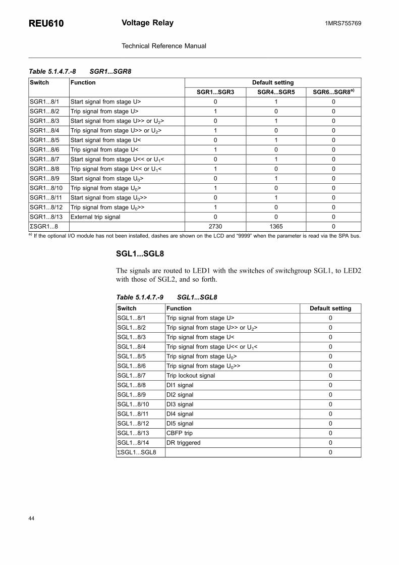
Table 5.1.4.7.-8 SGR1...SGR8
Switch Function Default setting
SGR1...SGR3 SGR4...SGR5 SGR6...SGR8a)
SGR1...8/1 Start signal from stage U> 0 1 0
SGR1...8/2 Trip signal from stage U> 1 0 0
SGR1...8/3 Start signal from stage U>> or U2> 0 1 0
SGR1...8/4 Trip signal from stage U>> or U2> 1 0 0
SGR1...8/5 Start signal from stage U< 0 1 0
SGR1...8/6 Trip signal from stage U< 1 0 0
SGR1...8/7 Start signal from stage U<< or U1< 0 1 0
SGR1...8/8 Trip signal from stage U<< or U1< 1 0 0
SGR1...8/9 Start signal from stage U0> 0 1 0
SGR1...8/10 Trip signal from stage U0> 1 0 0
SGR1...8/11 Start signal from stage U0>> 0 1 0
SGR1...8/12 Trip signal from stage U0>> 1 0 0
SGR1...8/13 External trip signal 0 0 0
ΣSGR1...8 2730 1365 0a) If the optional I/O module has not been installed, dashes are shown on the LCD and “9999” when the parameter is read via the SPA bus.
SGL1...SGL8
The signals are routed to LED1 with the switches of switchgroup SGL1, to LED2with those of SGL2, and so forth.
Table 5.1.4.7.-9 SGL1...SGL8
Switch Function Default setting
SGL1...8/1 Trip signal from stage U> 0
SGL1...8/2 Trip signal from stage U>> or U2> 0
SGL1...8/3 Trip signal from stage U< 0
SGL1...8/4 Trip signal from stage U<< or U1< 0
SGL1...8/5 Trip signal from stage U0> 0
SGL1...8/6 Trip signal from stage U0>> 0
SGL1...8/7 Trip lockout signal 0
SGL1...8/8 DI1 signal 0
SGL1...8/9 DI2 signal 0
SGL1...8/10 DI3 signal 0
SGL1...8/11 DI4 signal 0
SGL1...8/12 DI5 signal 0
SGL1...8/13 CBFP trip 0
SGL1...8/14 DR triggered 0
ΣSGL1...SGL8 0
44
REU610REU610 Voltage Relay
Technical Reference Manual
1MRS755769

45
New trip indication timer
The new trip indication timer can be configured to allow a second trip indication onthe LCD. When several protection stages trip, the first trip indication is displayeduntil the time, as specified by the NEW TRIP IND. setting value, has expired. Afterthis, a new trip indication can displace the old one. The basic protection functionsare not affected by the NEW TRIP IND. setting.
Table 5.1.4.7.-10 New trip indication timer
Setting Description Setting range Default setting
New tripindication
New trip indication timer in minutes 0...998 60
No new trip indication allowed until theprevious one has been manuallycleared.
999 -
Non-volatile memory settings
Non-volatile memory is backed up by a battery; the battery must beinserted and charged.
The table below presents data which can be configured to be stored in the non-volatile memory. All of the functions mentioned below can be selected separatelywith switches 1...5 either via the HMI or the SPA bus.
Table 5.1.4.7.-11 Memory settings
Setting Switch Function Default setting
Non-volatilememory settings
1 * 0 = operation indication messages andLEDs are cleared
* 1 = operation indication messages andLEDs are retaineda)
1
2 * 1 = disturbance recorder data is retained a) 1
3 * 1 = event codes are retaineda) 1
4 * 1 = recorded data and information on thenumber of starts of the protection stagesare retaineda)
1
5 * 1 = the real-time clock is running alsoduring loss of auxiliary voltagea)
1
Σ 31a) The prerequisite is that the battery has been inserted and is charged.
When all switches are set to zero, the battery supervision is disabled.
Voltage Relay
Technical Reference Manual
REU610REU6101MRS755769

5.1.4.8. Technical data on protection functions
Table 5.1.4.8.-1 Overvoltage protection, stages U>, U>> and U2>
Feature Stage U> Stage U>> Stage U2>
Set start value U>, U>> and U2>:
-at definite-time characteristic 0.60...1.40 × Un 0.80...1.60 × Un 0.05...1.00 × Un
-at IDMT characteristic 0.60...1.25 × Una) 0.80...1.25 × Un
a) 0.05...1.00 × Un
Start time, typical 60 ms 50 ms 50 ms
Time/voltage characteristic:
-definite-time operate time, t>, t>> 0.06...600 s 0.05...600 s 0.05...600 s
-IDMT curve A curve A curve A
curve B curve B curve B
time multiplier, k>, k>> 0.05...2.00 0.05...2.00 0.05...2.00
Resetting time, typical/maximum 70/80 msb) 70/80 ms 70/80 ms
Retardation time, typical 30 ms 30 ms 50 ms
Set resetting time, tr> 0.07...60.0 - -
Drop-off/pick-up ratio, D/P> 0.95...0.99 0.95...0.99 0.96
Operate time accuracy:
-at definite-time characteristic ±2% of the setoperate time or±25 ms
±2% of the setoperate time or±25 ms
±2% of the setoperate time or±25 ms
-at IDMT characteristic ±25 ms + theaccuracyappearing whenthe measuredvoltage varies±3%
±25 ms + theaccuracyappearing whenthe measuredvoltage varies±3%
±25 ms + theaccuracyappearing whenthe measuredvoltage varies±3%
Operation accuracy ±1.5% of the setstart value
±1.5% of the setstart value
-
-0.05...0.15 × Un - - ±10% of the setstart value
-0.15...1.00 × Un - - ±5% of the setstart value
a) Because of the maximum measured voltage (2 × Un), the setting value 1.25 is used for the IDMTcalculation if the set value is greater than 1.25. This makes the operate time faster than the theoreticalIDMT curve. However, the stage always starts according to the set value.
b) Resetting time of the trip signal.
Table 5.1.4.8.-2 Undervoltage protection, stages U<, U<< and U1<
Feature Stage U< Stage U<< Stage U1<
Set start value U<, U<< and U1<:
-at definite-time characteristic 0.20...1.20 × Un 0.20...1.20 × Un 0.20...1.20 × Un
-at IDMT characteristic 0.20...1.20 × Un 0.20...1.20 × Un 0.20...1.20 × Un
Start time, typical 80 ms 50 ms 50 ms
Time/voltage characteristic:
-at definite operate time, t<, t<< 0.10...600 s 0.10...600 s 0.10...600 s
-IDMT curve C curve C curve C
time multiplier, k<, k<< 0.10...2.00 0.10...2.00 0.10...2.00
Resetting time, typical/maximum 70/80 msa) 70/80 ms 70/80 ms
46
REU610REU610 Voltage Relay
Technical Reference Manual
1MRS755769

47
Feature Stage U< Stage U<< Stage U1<
Retardation time, typical 30 ms 30 ms 50 ms
Set resetting time, tr< 0.07...60.0 s - -
Drop-off/pick-up ratio, D/P< 1.01...1.05 1.01...1.05 1.04
Operate time accuracy:
-at definite-time characteristic ±2% of the setoperate time or±25 ms
±2% of the setoperate time or±25 ms
±2% of the setoperate time or±25 ms
-at IDMT characteristic ±25 ms + theaccuracyappearing whenthe measuredvoltage varies±3%
±25 ms + theaccuracyappearing whenthe measuredvoltage varies±3%
±25 ms + theaccuracyappearing whenthe measuredvoltage varies±3%
Operation accuracy ±1.5% of the setstart value
±1.5% of the setstart value
±5% of the setstart value
a) Resetting time of the trip signal.
Table 5.1.4.8.-3 Residual overvoltage protection, stages U0> and U0>>
Feature Stage U0> Stage U0>>
Set start value U0> and U0>>:
-at definite-time characteristic 2.0...80% Un 2.0...80% Un
Start time, typical 70 ms 60 ms
Time/voltage characteristic:
-definite-time operate time, t0>, t0>> 0.10...600 s 0.10...600 s
Resetting time, typical/maximum 30/50 msa) 30/50 msa)
Retardation time, typical 30 ms 30 ms
Set resetting time, t0r> 0.07...60.0 s 100 ms
Drop-off/pick-up ratio, typical 0.96 0.96
Operate time accuracy:
-at definite-time characteristic ±2% of the set operatetime or ±25 ms
±2% of the set operatetime or ±25 ms
Operation accuracy ±1.5% of the set startvalue or ±0.05% Un
±1.5% of the set startvalue or ±0.05% Un
a) Resetting time of the trip signal.
Table 5.1.4.8.-4 CBFP
Feature Value
Set operate time 0.10...60.0 s
Phase-to-phase voltage threshold forexternal triggering of the CBFP:
-pick-up/drop-off 0.15/0.10 × Un
5.1.5. Trip-circuit supervision
The trip-circuit supervision (TCS) detects open circuits, both when the circuitbreaker is open and closed, and trip-circuit supply failure.
Voltage Relay
Technical Reference Manual
REU610REU6101MRS755769

The trip-circuit supervision is based on a constant current injection principle: byapplying operating voltage for the circuit breaker, a constant current is forced toflow through the external trip circuit. If the resistance of the trip circuit exceeds acertain limit, due to oxidation or a bad contact, for instance, the trip-circuitsupervision is activated and a warning appears on the LCD together with a faultcode. The warning signal from the trip-circuit supervision can also be routed to SO2by setting switch SGF1/8 to 1.
Under normal operating conditions, the applied external voltage is divided betweenthe relay’s internal circuit and the external trip circuit so that at least 20 V remainsover the relay’s internal circuit. If the external trip circuit’s resistance is too high orthe internal circuit’s too low, due to welded relay contacts, for instance, the voltageover the relay’s internal circuit falls below 20 V (15...20 V), which activates the trip-circuit supervision.
The operation condition is:
U - R +R +R I 20 V AC/DCc ext int s tc( )× ≥ (5)
Uc = operating voltage over the supervised trip circuitIc = current flowing through the trip circuit, ~1.5 mARext = external shunt resistorRint = internal shunt resistor, 1 kΩRs = trip coil resistance
The external shunt resistor is used to enable trip-circuit supervision also when thecircuit breaker is open.
The resistance of the external shunt resistor is to be calculated so that it does notcause malfunction of the trip-circuit supervision or affect the operation of the tripcoil. Too high resistance causes too high voltage drop, which in turn results in theoperation conditions not being fulfilled, whereas too low resistance may causefaulty operation of the trip coil.
The following values are recommended for the external resistor, Rext:
Table 5.1.5.-1 Recommended values for Rext
Operating voltage, Uc Shunt resistor Rext
48 V DC 1.2 kΩ, 5 W
60 V DC 5.6 kΩ, 5 W
110 V DC 22 kΩ, 5 W
220 V DC 33 kΩ, 5 W
The circuit breaker is to be provided with two external contacts, one opening andone closing contact. The closing contact is to be connected in parallel with theexternal shunt resistor, which enables trip-circuit supervision when the circuitbreaker is closed. The opening contact, on the contrary, is to be connected in serieswith the external shunt resistor, which enables trip-circuit supervision when thecircuit breaker is open; see Fig. 5.1.5.-1.
48
REU610REU610 Voltage Relay
Technical Reference Manual
1MRS755769

49
Trip-circuit supervision can be selected either via the HMI or with SPA parameterV113.
&
%
�&>)�(+)
3��
A@�@
����
�'
��
�
��
��
��� �
�
�
A=9
���
������
. $�%�$ ��$.��: F$$�!
.��. .:��; !$!�
A040329_2
Fig. 5.1.5.-1 Connecting the trip-circuit supervision using two external contacts andthe external resistor in the trip circuit
5.1.6. Trip lockout function
The trip lockout function is used to prevent accidental closing of the circuit breakerafter a trip. The trip lockout function must be locally reset with a separate resetcommand before the circuit breaker can be closed again. This function is usefulwhen the trip output contact of the relay is latched or the open circuit of the circuitbreaker remains activated.
The trip lockout function is selected in SGF1. When selected, PO3 is dedicated tothis function. As long as no trip occurs, PO3 is closed.
Every signal which has been routed to PO3 via the output signal matrix activates thetrip lockout function and opens the contacts of PO3. When the contacts haveopened, they are locked into the open state.
The trip lockout function can also be activated externally, via a digital input. Thetrip lockout function can be reset via a digital input, the HMI or SPA parameterV103, but not before the signal which activated the function has been reset.
Voltage Relay
Technical Reference Manual
REU610REU6101MRS755769

In case of loss of auxiliary power when the trip lockout function is in use, thecontacts of PO3 return to the same state as before the loss, provided that the batteryhas been inserted and is charged. If no battery has been inserted, the trip lockoutfunction is activated and the contacts of PO3 remain open when the auxiliary poweris switched on again.
5.1.7. Trip counters for circuit-breaker condition monitoring
The trip counters for circuit-breaker condition monitoring provide history data,which can be used for circuit-breaker service scheduling. With this information, theservice cycle can be estimated for the future.
The monitoring function consists of four counters, which count the number of tripsignals generated to the circuit breaker by the relay. Every time a stage generates atrip signal, the corresponding counter value is increased by one. The number of tripsis stored in the non-volatile EEPROM memory.
There are separate counters for the different protection stages. The overvoltagestages (U>, U>> and U2>), undervoltage stages (U<, U<< and U1<) and residualovervoltage stages (U0> and U0>>) have a common trip counter each, whereas thereis an own trip counter for the external trip.
The counters can be read via the HMI or SPA parameters V9...V12 and cleared viaSPA parameter V166. When a counter reaches its maximum value, it rolls over.
In case several stages trip during the same fault sequence, only thecounter of the stage which tripped first is increased by one.
5.1.8. Indicator LEDs and operation indication messages
The operation of the relay can be monitored via the HMI by means of LEDindications and text messages on the LCD. On the front panel of the relay there arethree indicator LEDs with fixed functionality:
* Green indicator LED (ready)* Yellow indicator LED (start/alarm)* Red indicator LED (trip)
In addition, there are eight programmable LEDs and an indicator LED for frontcommunication. Refer to the Operator’s Manual for a more thorough presentation.
The indication messages on the LCD have a certain priority order. If different typesof indications are activated simultaneously, the message with the highest priorityappears on the LCD.
50
REU610REU610 Voltage Relay
Technical Reference Manual
1MRS755769

51
The priority order of the operation indication messages:
1. CBFP
2. Trip
3. Start/Alarm
5.1.9. Demand values
The relay provides three different kinds of demand values.
The first value shows the average voltage of all three phase-to-phase voltagesmeasured during one minute. The value is updated once a minute.
The second value shows the average voltage during an adjustable time range,ranging from 0 to 999 minutes, with an accuracy of one minute. This value isupdated at the expiration of each time range.
The third value shows the highest one-minute average voltage value measuredduring the previous time range. However, if the time range is set to zero, only theone-minute and the maximum average voltage value is shown. The maximum valueis the highest one-minute mean value since the last reset.
The demand voltage values can be set to zero through serial communication usingSPA parameter V102. The average voltage values are also reset if SPA parameterV105 is changed or the relay is reset.
5.1.10. Commissioning tests
The following two product functions can be used during the commissioning of therelay: function test and digital input test.
The function test is used for testing the configuration as well as the connectionsfrom the relay. By selecting this test, the internal signals from the protection stages,the motor start-up signal, the external trip signal and the IRF function can beactivated one by one. Provided that the signals have been set to be routed to theoutput contacts (PO1...PO3 and SO1...SO5) with the switches of SGR1...SGR8, theoutput contacts are activated and their corresponding event codes are generatedwhen the test is run. However, activation of the internal signals from the protectionstages, the external trip signal and the IRF function do not generate an event code.
The digital input test is used for testing the connections to the relay. The state of thedigital inputs can be monitored via the HMI.
Refer to the Operator’s Manual for instructions on how to perform the tests.
Voltage Relay
Technical Reference Manual
REU610REU6101MRS755769

5.1.11. Disturbance recorder
5.1.11.1. Function
The relay features an integrated disturbance recorder which continuously capturesthe curve forms of the voltages as well as the status of both internal signals and theexternal digital input signals and stores these in the memory.
Triggering of the recorder generates an event code. After the recorder has beentriggered, it continues to record data for a pre-defined post-triggering time. Anasterisk is shown on the LCD on completion of the recording. The status of therecording can also be viewed using SPA parameter V246.
As soon as the recorder has been triggered and the recording has finished, therecording can be uploaded and analyzed by means of a PC provided with a specialprogram.
5.1.11.2. Disturbance recorder data
One recording contains data from the four analog channels and up to eight digitalchannels. The analog channels, whose data is stored either as RMS curves or asmomentary measured values, are the voltages measured by the relay. The digitalchannels, referred to as digital signals, are start and trip signals from the protectionstages and the digital input signals linked to the relay.
The user can select up to eight digital signals to be recorded. If more than eightsignals are selected, the first eight signals are stored, beginning with the internalsignals followed by the digital input signals.
The digital signals to be stored are selected with parameters V238 and V243; seeTable 5.1.17.-5 and Table 5.1.17.-6.
The recording length varies according to the selected sampling frequency. The RMScurve is recorded by selecting the sampling frequency to be the same as the nominalfrequency of the relay. The sampling frequency is selected with SPA parameter M15;see the table below for details.
Table 5.1.11.2.-1 Sampling frequency
Nominal frequency Hz Sampling frequency Hz Cycles
50 800 250
400 500
50a) 4000
60 960 250
480 500
60a) 4000a) RMS curve.
Recording length:
52
REU610REU610 Voltage Relay
Technical Reference Manual
1MRS755769

53
s =Cycles
Nominal frequency [Hz][ ] (6)
Changing the setting values of parameters M15, V238 and V243 is allowed onlywhen the recorder is not triggered.
The post-triggering recording length defines the time during which the recordercontinues to store data after it has been triggered. The length can be changed withSPA parameter V240. If the post-triggering recording length is defined to be thesame as the total recording length, no data stored prior to the triggering is retained inthe memory. By the time the post-triggering recording finishes, a completerecording is created.
Triggering of the recorder immediately after it has been cleared or the auxiliaryvoltage connected may result in a shortened total recording length. Disconnection ofthe auxiliary voltage after the recorder has been triggered, but before the recordinghas finished, on the other hand, may result in a shortened post-triggering recordinglength. This, however, does not affect the total recording length.
At a power reset, triggered recorder data is retained in the memory provided that ithas been defined non-volatile.
5.1.11.3. Control and indication of disturbance recorder status
It is possible to control and monitor the recording status of the disturbance recorderby writing to and reading SPA parameters M1, M2 and V246. Reading SPAparameter V246 returns either the value 0 or 1, indicating whether the recorder hasnot been triggered or triggered and ready to be uploaded. Event code E31 isgenerated the moment the disturbance recorder is triggered. If the recorder is readyto be uploaded, this is also indicated by an asterisk shown in the lower right-handcorner of the LCD when it is in the idle mode. Indication can also be routed toprogrammable LEDs.
Writing the value 1 to SPA parameter M2 clears the recorder memory and enablesthe triggering of the recorder. Recorder data can be cleared by performing a masterreset, that is, clearing indications and memorized values and unlatching outputcontacts.
Writing the value 2 to SPA parameter V246 restarts the unloading process by settingthe time stamp and the first data ready to be read.
5.1.11.4. Triggering
The user can select one or several internal or external digital input signals to triggerthe disturbance recorder, either on the rising or falling edge of the signal(s).Triggering on the rising edge means that the post-triggering recording sequencestarts when the signal is activated. Correspondingly, triggering on the falling edgemeans that the post-triggering recording sequence starts when the active signal isreset.
Voltage Relay
Technical Reference Manual
REU610REU6101MRS755769

The trigger signal(s) and the edge are selected with SPA parameters V236...V237and V241...V242; see Table 5.1.17.-5 and Table 5.1.17.-6. The recorder can also betriggered manually with SPA parameter M1.
Triggering of the disturbance recorder is only possible if the recorder is not alreadytriggered.
5.1.11.5. Settings and unloading
The setting parameters for the disturbance recorder are V parameters V236...V238,V240...V243 and V246, and M parameters M15, M18, M20 and M80...M83.
Unloading correct information from the recorder requires that M80 and M83 havebeen set. Unloading is done by using a PC application. The uploaded recorder datais stored in separate files defined by the comtrade® format.
5.1.11.6. Event code of the disturbance recorder
The disturbance recorder generates an event code on triggering (E31) and clearing(E32) the recorder. The event mask is determined using SPA parameter V155.
5.1.12. Recorded data of the last events
The relay records up to five events. This enables the user to analyze the last fivefault conditions in the electrical power network. Each event includes the measuredvoltages, start durations and time stamp, for instance. Additionally, information onthe number of starts of the stages and trips is provided.
Recorded data is non-volatile by default, provided that the battery has been insertedand is charged. A master reset, that is, clearing of indications and memorized valuesand unlatching of output contacts, erases the contents of the stored events and thenumber of starts of the stages.
The number of trips is stored in the non-volatile memory (EEPROM)and is thereby not cleared when performing a master reset. The numberof trips can be erased by entering the value 1 into parameter V166.
The relay collects data during fault conditions. When all start signals have been resetor a stage trips, the collected data and time stamp is stored as EVENT1 and thepreviously stored events move one step forward. When a sixth event is stored, theoldest event is cleared.
54
REU610REU610 Voltage Relay
Technical Reference Manual
1MRS755769

55
Table 5.1.12.-1 Recorded data
REGISTER Data description
EVENT1 * Phase-to-phase voltage U12 measured at a time of trip as a multiple of therated voltage, Un. The same applies to phase-to-phase voltages U23 andU31.
* Residual voltage U0 measured at a time of trip as a percentage of the ratedvoltage Un.
* Maximum voltage value of the phase-to-phase voltages during the last faultconditions in the network, measured as a multiple of the rated voltage Un
* Minimum voltage value of the phase-to-phase voltages during the last faultconditions in the network, measured as a multiple of the rated voltage Un.
* Maximum voltage value of the negative phase-sequence voltage during thelast fault conditions in the network, measured as a multiple of the ratedvoltage Un. If stage U>> is not based on negative phase-sequence voltageU2s, dashes are shown on the LCD and "999" when read via serialcommunication.
* Minimum voltage value of the positive phase-sequence voltage during thelast fault conditions in the network, measured as a multiple of the ratedvoltage Un. If stage U<< is not based on positive phase-sequence voltageU1s, dashes are shown on the LCD and "999" when read via serialcommunication.
* Maximum voltage value of the residual voltage U0 during the last faultconditions in the network, measured as a percentage of the rated voltage Un.
* Duration of the last start of stages U>, U>>/U2>, U<, U<</U1<, U0>, U0>>and of the external trip, shown as a percentage of the set operate time, or ofthe calculated operate time at IDMT characteristic. A value other than zeroindicates that the corresponding stage has started whereas a value which is100% of the set or calculated operate time indicates that the operate time ofthe stage has elapsed, that is, the stage has tripped. If the operate time of astage has elapsed but the stage is blocked, the value is 99% of the set orcalculated operate time.
* Time stamp for the event. The time when the collected data was stored. Thetime stamp is displayed in two registers, one including the date expressed asyy-mm-dd, and the other including the time expressed as HH.MM;SS.sss.
EVENT 2 Same as EVENT 1.
EVENT 3 Same as EVENT 1.
EVENT 4 Same as EVENT 1.
EVENT 5 Same as EVENT 1.
Number ofstarts
The number of times each protection stage U>, U>>/U2<, U<, U<</U1<, U0>,U0>> has started, counting up to 999.
Number oftrips
Number of trips:* Overvoltage stages U>, U>> and U2>* Undervoltage stages U<, U<< and U1<* Residual overvoltage stages U0> and U0>>* External tripWhen the counters reach their maximum values (65535), they roll over.
5.1.13. Communication ports
The relay is provided with an optical communication port (infrared) on the frontpanel. Rear communication is optional and requires a communication module,which can be provided with either a plastic fibre-optic, combined fibre-optic (plastic
Voltage Relay
Technical Reference Manual
REU610REU6101MRS755769

and glass) or RS-485 connection. The relay is connected to an automation systemvia the rear connection. The optional rear communication module allows the use ofeither the SPA bus, IEC 60870-5-103 or Modbus communication protocol.
For connection to the DNP 3.0 communication system, the relay can be providedwith an optional DNP 3.0 rear communication module with RS-485 connection. Forfurther information on optional rear communication module connections, refer toSection 5.2.2. Serial communication connections.
A051551
Fig. 5.1.13.-1 Communication port
1) Front connection for local communication
The relay is connected to a PC used for local parameterization via the infrared porton the front panel. The front connection allows the use of the SPA bus protocol only.
The optical front connection galvanically isolates the PC from the relay. The frontconnection can be used in two different ways: wirelessly using a PC compatible tothe IrDA®‚ Standard specifications or using a specific front communication cable(refer to Section 6. Ordering information). The cable is connected to the serial RS-232 port of the PC. The optical stage of the cable is powered by RS-232 controlsignals. The cable has a fixed baud rate of 9.6 kbps.
The following serial communication parameters are to be set for RS-232:
* Number of data bits: 7* Number of stop bits: 1* Parity: even* Baud rate: 9.6 kbps
Relay data such as events, setting values and all input data and memorized valuescan be read via the front communication port.
When setting values are altered via the front communication port, the relay checksthat the entered parameter values are within the permitted setting range. If an enteredvalue is too high or too low, the setting value remains unchanged.
56
REU610REU610 Voltage Relay
Technical Reference Manual
1MRS755769
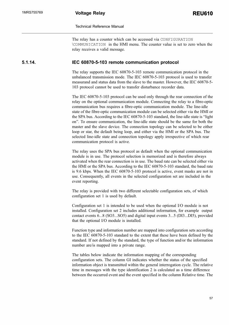
57
The relay has a counter which can be accessed via CONFIGURATION\COMMUNICATION in the HMI menu. The counter value is set to zero when therelay receives a valid message.
5.1.14. IEC 60870-5-103 remote communication protocol
The relay supports the IEC 60870-5-103 remote communication protocol in theunbalanced transmission mode. The IEC 60870-5-103 protocol is used to transfermeasurand and status data from the slave to the master. However, the IEC 60870-5-103 protocol cannot be used to transfer disturbance recorder data.
The IEC 60870-5-103 protocol can be used only through the rear connection of therelay on the optional communication module. Connecting the relay to a fibre-opticcommunication bus requires a fibre-optic communication module. The line-idlestate of the fibre-optic communication module can be selected either via the HMI orthe SPA bus. According to the IEC 60870-5-103 standard, the line-idle state is “lighton”. To ensure communication, the line-idle state should be the same for both themaster and the slave device. The connection topology can be selected to be eitherloop or star, the default being loop, and either via the HMI or the SPA bus. Theselected line-idle state and connection topology apply irrespective of which rearcommunication protocol is active.
The relay uses the SPA bus protocol as default when the optional communicationmodule is in use. The protocol selection is memorized and is therefore alwaysactivated when the rear connection is in use. The baud rate can be selected either viathe HMI or the SPA bus. According to the IEC 60870-5-103 standard, the baud rateis 9.6 kbps. When the IEC 60870-5-103 protocol is active, event masks are not inuse. Consequently, all events in the selected configuration set are included in theevent reporting.
The relay is provided with two different selectable configuration sets, of whichconfiguration set 1 is used by default.
Configuration set 1 is intended to be used when the optional I/O module is notinstalled. Configuration set 2 includes additional information, for example outputcontact events 6...8 (SO3...SO5) and digital input events 3...5 (DI3...DI5), providedthat the optional I/O module is installed.
Function type and information number are mapped into configuration sets accordingto the IEC 60870-5-103 standard to the extent that these have been defined by thestandard. If not defined by the standard, the type of function and/or the informationnumber are/is mapped into a private range.
The tables below indicate the information mapping of the correspondingconfiguration sets. The column GI indicates whether the status of the specifiedinformation object is transmitted within the general interrogation cycle. The relativetime in messages with the type identification 2 is calculated as a time differencebetween the occurred event and the event specified in the column Relative time. The
Voltage Relay
Technical Reference Manual
REU610REU6101MRS755769

measurand multiplied by the normalize factor is proportional to the rated value.Therefore, the maximum value of each measurand is the normalize factor multipliedby the rated value.
Table 5.1.14.-1 Information mapping of configuration set 1 and 2
Event reason
Eventcode
Configurationset1
Configurationset2
Functiontype
Inform
ationnumber
GI
Relativetime
Typeidentification
Disturbance recorder Triggered/Cleared 0E31/0E32
X X 178 100 - - 1
HMI Setting password Opened/Closed 0E33/0E34
X X 178 101 - - 1
HMI Communication password Opened/Closed 0E35/0E36
X X 178 102 - - 1
U> Start/Reset 1E1/1E2
X X 165 84 X 1E1 2
U> Trip/Reset 1E3/1E4
X X 165 90 - 1E1 2
U>> or U2> Start/Reset 1E5/1E6
X X 165 94 X 1E5 2
U>> or U2> Trip/Reset 1E7/1E8
X X 165 91 - 1E5 2
U< Start/Reset 1E9/1E10
X X 166 84 X 1E9 2
U< Trip/Reset 1E11/1E12
X X 166 90 - 1E9 2
U<< or U1< Start/Reset 1E13/1E14
X X 166 94 X 1E13 2
U<< or U1< Trip/Reset 1E15/1E16
X X 166 91 - 1E13 2
U0> Start/Reset 1E17/1E18
X X 170 84 X 1E17 2
U0> Trip/Reset 1E19/1E20
X X 170 90 - 1E17 2
U0>> Start/Reset 1E21/1E22
X X 170 94 X 1E21 2
U0>> Trip/Reset 1E23/1E24
X X 170 91 - 1E21 2
Trip Lockout/Reset 1E25/1E26
X X 10 223 X - 1
External Trip/Reset 1E27/1E28
X X 10 222 - - 1
CBFP Activated/Reset 1E29/1E30
X X 160 85 - - 1
PO1 Activated/Reset 2E1/2E2
X X 251 27 X - 1
58
REU610REU610 Voltage Relay
Technical Reference Manual
1MRS755769

59
Event reason
Eventcode
Configurationset1
Configurationset2
Functiontype
Inform
ationnumber
GI
Relativetime
Typeidentification
PO2 Activated/Reset 2E3/2E4
X X 251 28 X - 1
PO3 Activated/Reset 2E5/2E6
X X 251 29 X - 1
SO1 Activated/Reset 2E7/2E8
X X 251 30 X - 1
SO2 Activated/Reset 2E9/2E10
X X 251 31 X - 1
SO3 Activated/Reset 2E11/2E12
- X 251 32 X - 1
SO4 Activated/Reset 2E13/2E14
- X 251 33 X - 1
SO5 Activated/Reset 2E15/2E16
- X 251 34 X - 1
DI1 Activated/Deactivated 2E17/2E18
X X 249 231 X - 1
DI2 Activated/Deactivated 2E19/2E20
X X 249 232 X - 1
DI3 Activated/Deactivated 2E21/2E22
- X 249 233 X - 1
DI4 Activated/Deactivated 2E23/2E24
- X 249 234 X - 1
DI5 Activated/Deactivated 2E25/2E26
- X 249 235 X - 1
Table 5.1.14.-2 Information mapping of configuration set 1 and 2
Measurand
Norm
aliz
efactor
Ratedvalue
Configurationset1
Configurationset2
Functiontype
Inform
ationnumber
Typeidentification
Voltage U12 2.40 Un X X 135 143 9
Voltage U23 2.40 Un X X
Voltage U31 2.40 Un X X
Voltage U0 2.40 Un X X
Voltage U1s 2.40 Un X X
Voltage U2s 2.40 Un X X
Voltage Relay
Technical Reference Manual
REU610REU6101MRS755769

5.1.15. Modbus remote communication protocol
The master/slave protocol Modbus was first introduced by Modicon Inc. and iswidely accepted as a communication standard for industrial device controllers andPLCs. For the protocol definition, refer to Section 1.4. Product documentation.
The implementation of the Modbus protocol in the relay supports both the RTU andthe ASCII link mode. Both the link mode and the line setting parameters are user-configurable. The character codings of the link modes follow the protocoldefinition. The RTU character format is presented in Table 5.1.15.-1 and the ASCIIcharacter format in Table 5.1.15.-2:
Table 5.1.15.-1 RTU character format
Coding system 8-bit binary
Bits percharacter
1 start bit8 data bits, the least significant bit is sent first1 bit for even/odd parity; no bit if parity is not used1 stop bit if parity is used; 2 stop bits if parity is not used
Table 5.1.15.-2 ASCII character format
Coding system Two ASCII characters representing a hexadecimal number
Bits percharacter
1 start bit7 data bits, the least significant bit is sent first1 bit for even/odd parity; no bit if parity is not used1 stop bit if parity is used; 2 stop bits if parity is not used
The turnaround time (response time) of the relay depends on theamount of data requested in a query. Therefore, the turnaround timecan vary between approximately 20 and 100 ms. However, aturnaround timeout no lower than 150 ms is recommended for theModbus master.
The data address range in the Modbus network follows the protocoldefinition and starts from 0. Consequently, the data addresses inTable 5.1.15.1.-5...Table 5.1.15.1.-13 are decreased by one whentransferred over the network.
The Modbus data type digital input (DI) is commonly also referred toas 1X, coils as 0X, input register (IR) as 3X and holding register (HR)as 4X, of which the former is used here. Thus, HR 123, for instance,can also be referred to as register 400123.
60
REU610REU610 Voltage Relay
Technical Reference Manual
1MRS755769

61
5.1.15.1. Profile of Modbus
The Modbus protocol (ASCII or RTU) is selected via the HMI and can be used onlythrough the rear connection of the relay on the optional communication module.Modbus line settings, that is, parity, CRC byte order and baud rate, can be adjustedeither via the HMI or the SPA bus.
The implementation of the Modbus protocol in REU610 supports the followingfunctions:
Table 5.1.15.1.-1 Supported application functions
Function code Function description
01 Read coil statusReads the status of discrete outputs.
02 Read digital input statusReads the status of discrete inputs.
03 Read holding registersReads the contents of output registers.
04 Read input registersReads the contents of input registers.
05 Force single coilSets the status of a discrete output.
06 Preset single registerSets the value of a holding register.
08 DiagnosticsChecks the communication system between themaster and the slave.
15 Force multiple coilsSets the status of multiple discrete outputs.
16 Preset multiple registersSets the value of multiple holding registers.
23 Read/write holding registersExchanges holding registers in one query.
Table 5.1.15.1.-2 Supported diagnostic subfunctions
Code Name Description
00 Return query data The data in the query data field is returned (looped back)in the response. The entire response is to be identical tothe query.
01 Restartcommunicationoption
The slave’s peripheral port is initialized and restartedand the communication event counters are cleared.Before this, a normal response will be sent provided thatthe port is not in the listen only mode. However, if theport is in the listen only mode, no response will be sent.
04 Force listen onlymode
The slave is forced to enter the listen only mode forModbus communication.
10 Clear counters anddiagnostic register
All counters and the diagnostic register are cleared.
11 Return busmessage count
The number of messages in the communications systemdetected by the slave since its last restart, clear countersoperation or power up is returned in the response.
Voltage Relay
Technical Reference Manual
REU610REU6101MRS755769

Code Name Description
12 Return buscommunication errorcount
The number of CRC errors encountered by the slavesince its last restart, clear counters operation or powerup is returned in the response.
13 Return busexception errorcount
The number of Modbus exception responses sent by theslave since its last restart, clear counters operation orpower up is returned in the response.
14 Return slavemessage count
The number of messages addressed to the slave orbroadcast which the slave has processed since its lastrestart, clear counters operation or power up is returnedin the response.
15 Return slave noresponse count
The number of messages addressed to the slave forwhich a response (neither a normal response nor anexception response) has not been sent since its lastrestart, clear counters operation or power up is returnedin the response.
16 Return slave NACKresponse count
The number of messages addressed to the slave forwhich a NACK response has been sent is returned in theresponse.
18 Return buscharacter overruncount
The number of messages addressed to the slave forwhich it has not been able to send a response due to acharacter overrun since its last restart, clear countersoperation or power up is returned in the response.
Sending other subfunction codes than those listed above cause anIllegal data value response.
The Modbus protocol provides the following diagnostic counters:
Table 5.1.15.1.-3 Diagnostic counters
Name Description
Bus message count The number of messages in the communicationssystem detected by the slave since its last restart,clear counters operation or power up.
Bus communication error count The number of CRC or LRC errors encountered by theslave since its last restart, clear counters operation orpower up.
Bus exception error count The number of Modbus exception responses sent bythe slave since its last restart, clear counters operationor power up.
Slave message count The number of messages addressed to the slave orbroadcast which the slave has processed since its lastrestart, clear counters operation or power up.
62
REU610REU610 Voltage Relay
Technical Reference Manual
1MRS755769

63
Name Description
Slave no response count The number of messages addressed to the slave forwhich a response (neither a normal response nor anexception response) has not been sent since its lastrestart, clear counters operation or power up.
Slave NACK response count The number of messages addressed to the slave forwhich a NACK response has been sent.
Bus character overrun count The number of messages addressed to the slave forwhich it has not been able to send a response due to acharacter overrun since its last restart, clear countersoperation or power up.
The following exception codes may be generated by the Modbus protocol:
Table 5.1.15.1.-4 Possible exception codes
Code Name Description
01 Illegal function The slave does not support the requested function.
02 Illegal data address The slave does not support the data address or thenumber of items in the query is incorrect.
03 Illegal data value A value contained in the query data field is out of range.
04 Slave device failure An unrecoverable error has occurred while the slavewas attempting to perform the requested task.
If an Illegal data value exception response is generated whenattempting to preset multiple registers, the contents of the register towhich an illegal value has been imposed and of the following registersis not changed. Registers which have already been preset are notrestored.
User-defined registers
Reading of unwanted data in a data block wastes bandwidth and complicates datainterpretation. For optimum efficiency in Modbus communication, data hastherefore been organized into consecutive blocks. In addition, a set of programmableuser-defined registers (UDR) has been defined in the holding register area.
The first sixteen holding registers, that is, HR1...16, are user-defined registers. TheUDRs can be linked to any holding register, except for HR721...727, using SPAparameters 504V1...504V16. However, one UDR cannot be linked to another, thatis, linking cannot be nested. Each parameter contains the address of the holdingregister to which the UDR is linked.
If a UDR is linked to a non-existent holding register, reading from the register failsand an Illegal address exception response is sent. Giving the link addressthe value 0 disables the UDR. If the master reads from a disabled UDR, the value 0is returned.
Voltage Relay
Technical Reference Manual
REU610REU6101MRS755769

The UDRs are mirrored in HR385…400.
Fault records
The data recorded during a fault sequence is called a fault record (FR). The slavestores the five latest fault records. When a sixth record is stored, the oldest record isdeleted.
To read a fault record:
1. Write a preset single register command (function 06) to HR601 using a selectioncode as data value.
2. Read the selected fault record (function 04) from HR601, register count 28.
Selection code 1: the master reads the oldest unread record
Status register 3 (HR403) informs whether there are unread fault records (seeFig. 5.1.15.1.-2). If there is one or several unread fault records, the master can readthe contents using selection code 1.
The fault record contains a sequence number which makes it possible for the masterto determine whether one or several unread fault records have been deleted due tooverflow. The master compares the sequence number to that of the previously readfault record.
The slave keeps track of which fault record is currently the oldest unread. Themaster can continue reading fault records for as long as Status register 3 indicatesthat there are unread records.
* Special case 1: If there are no unread fault records, the contents of the last readrecord is returned. If the buffer is empty, however, the registers contain onlyzeros. This is the only time when sequence number zero appears.
* Special case 2: If the master tries to read the next unread fault record withoutentering selection code 1 again, the contents of the last read record will bereturned.
Selection code 2: the master reads the oldest stored record
By resetting the read pointer using selection code 2, the master can read the oldeststored fault record. After this, the master can continue reading the following recordsusing selection code 1, irrespective of whether they have been read before.
Resetting the read pointer does not affect the sequence number of thefault record.
A master reset, that is, clearing of indications and memorized valuesand unlatching of output contacts, clears the fault records, after whichthe sequence number starts from 1 again.
64
REU610REU610 Voltage Relay
Technical Reference Manual
1MRS755769

65
Event records
Modbus events are derived from SPA events. With a few exceptions, SPA eventsupdate binary points in the DI and the packed HR area. Simultaneously, acorresponding Modbus event record is generated. The event record contains theModbus DI/CO data point address and the value to which the point has changed (0or 1). SPA events lacking a corresponding DI/CO data point are shown as SPAchannel and event code (informative event) in the event record. The maximumcapacity of the Modbus event buffer is 99 events. The time stamp of Modbus eventsis extended to contain complete information, from date to millisecond.
To read an event record:
1. Write a preset single register command (function 06) to HR671 using a selectioncode as data value.
2. Read the selected fault record (function 04) from HR672, register count 8.
Alternatively, a fault record can be read using one command (function 23) only.
Selection code 1: reading the oldest unread record
Status register 3 (HR403) informs whether there are unread event records (seeFig. 5.1.15.1.-2). If there is one or several unread event records, the master can readthe contents using selection code 1.
The event record contains a sequence number which makes it possible for the masterto determine whether one or several unread event records have been deleted due tooverflow by comparing it to the sequence number of the previously read eventrecord.
The slave keeps track of which event record is currently the oldest unread. Themaster can continue reading event records for as long as Status register 3 indicatesthat there are unread records.
* Special case 1: If there are no unread event records, the contents of the last readrecord is returned. If the buffer is empty, however, the registers contain onlyzeros. This is the only time when sequence number zero appears.
* Special case 2: If the master tries to read the next unread event record withoutentering selection code 1 again, the contents of the last read record is returned.
Selection code 2: reading the oldest stored record
By resetting the read pointer using selection code 2, the master can read the oldeststored event record. After this, the master can continue reading the followingrecords using selection code 1, irrespective of whether they have been read before.
Resetting the read pointer does not affect the sequence number of theevent record.
Voltage Relay
Technical Reference Manual
REU610REU6101MRS755769

Selection code -1...-99
With selection code -1...-99, the master can move backwards from the newest eventas many events as defined by the selection code and read that specific event record.After this, the master can continue reading the following records using selectioncode 1, irrespective of whether they have been read before.
* Special case: If there is not as many events in the buffer as specified by theselection code, the oldest stored event is read.
Selection code 3
The Modbus event buffer is cleared with selection code 3. Clearing the buffer doesnot require any read operation to follow.
Digital inputs
As the master may not detect the state changes of all digital signals when scanning,an additional change detect (CD) indication bit is created for every momentaryindication point; see the example below.
= #&+)"�5
="')&���&"-'
="')&���&"-'
="')&���&"-'
="')&���&"-'
�1"+!&�-&)&,)
A040332
Fig. 5.1.15.1.-1 Change detection bit
If the momentary value of an indication bit has changed two or more times since themaster last read it, the CD bit is set to one. When the CD bit has been read, it is setto zero.
The momentary and the CD bit of a certain indication point always occur as a pair inthe Modbus memory map.
66
REU610REU610 Voltage Relay
Technical Reference Manual
1MRS755769

67
Modbus data mapping
There are two types of monitoring data: digital indications and measurands. Forconvenience and efficiency, the same data can be read from different data areas.Measurands and other 16-bit values can be read either from the IR or HR (read-only) area and digital indication values from either the DI or coil (read-only) area. Itis also possible to read the status of the DIs as packed 16-bit registers from both theIR and the HR area.
Consequently, all monitoring data can be read as consecutive blocks of data fromthe IR or HR area.
The register and bit addresses are presented in the tables below. Some registerstructures are presented in separate sections below.
The HR and IR values are unsigned 16-bit integers unless otherwisespecified.
Table 5.1.15.1.-5 Mapping of Modbus data: user-defined registers
Description HR/IR address(.bit)
DI/Coil bitaddress
Writeable Value range Comment
UDR 1 1 or 385
UDR 2 2 or 386
UDR 3 3 or 387
UDR 4 4 or 388
UDR 5 5 or 389
UDR 6 6 or 390
UDR 7 7 or 391
UDR 8 8 or 392
UDR 9 9 or 393
UDR 10 10 or 394
UDR 11 11 or 395
UDR 12 12 or 396
UDR 13 13 or 397
UDR 14 14 or 398
UDR 15 15 or 399
UDR 16 16 or 400
Table 5.1.15.1.-6 Mapping of Modbus data: status registers
Description HR/IR address(.bit)
DI/Coil bitaddress
Writeable Value range Comment
Status register 1 401 IRF code See Structure 1
Status register 2 402 Warningcodes
See Structure 1
Status register 3 403 See Structure 1
Voltage Relay
Technical Reference Manual
REU610REU6101MRS755769

Table 5.1.15.1.-7 Mapping of Modbus data: analog data
Description HR/IR address(.bit)
DI/Coil bitaddress
Writeable Value range Comment
Phase-to-phase voltage U12 404 0...200 0...2 × Un
Phase-to-phase voltage U23 405 0...200 0...2 × Un
Phase-to-phase voltage U31 406 0...200 0...2 × Un
Residual voltage U0 407 0...200 0...200% Un
Positive phase-sequence voltage 408 0...200 0...2 × Un
Negative phase-sequence voltage 409 0...200 0...2 × Un
Table 5.1.15.1.-8 Mapping of Modbus data: digital data
Description HR/IR address (.bit) DI/Coil bitaddress
Writeable Valuerange
Comment
Start signal from stage U> 410.00 1 0/1 1 = activated
Start signal from stage U> CD 410.01 2
Trip signal from stage U> 410.02 3 0/1 1 = activated
Trip signal from stage U> CD 410.03 4
Start signal from stage U>> 410.04 5 0/1 1 = activated
Start signal from stage U>> CD 410.05 6
Trip signal from stage U>> 410.06 7 0/1 1 = activated
Trip signal from stage U>> CD 410.07 8
Start signal from stage U< 410.08 9 0/1 1 = activated
Start signal from stage U< CD 410.09 10
Trip signal from stage U< 410.10 11 0/1 1 = activated
Trip signal from stage U< CD 410.11 12
Start signal from stage U<< 410.12 13 0/1 1 = activated
Start signal from stage U<< CD 410.13 14
Trip signal from stage U<< 410.14 15 0/1 1 = activated
Trip signal from stage U<< CD 410.15 16
Start signal from stage U0> 411.00 17 0/1 1 = activated
Start signal from stage U0> CD 411.01 18
Trip signal from stage U0> 411.02 19 0/1 1 = activated
Trip signal from stage U0> CD 411.03 20
Start signal from stage U0>> 411.04 21 0/1 1 = activated
Start signal from stage U0>> CD 411.05 22
Trip signal from stage U0>> 411.06 23 0/1 1 = activated
Trip signal from stage U0>> CD 411.07 24
Trip lockout 411.08 25 0/1 1 = activated
Trip lockout CD 411.09 26
External trip 411.10 27 0/1 1 = activated
External trip CD 411.11 28
CBFP 411.12 29 0/1 1 = activated
CBFP CD 411.13 30
PO1 contact 411.14 31 0/1 1 = activated
PO1 contact CD 411.15 32
PO2 contact 412.00 33 0/1 1 = activated
68
REU610REU610 Voltage Relay
Technical Reference Manual
1MRS755769

69
Description HR/IR address (.bit) DI/Coil bitaddress
Writeable Valuerange
Comment
PO2 contact CD 412.01 34
PO3 contact 412.02 35 0/1 1 = activated
PO3 contact CD 412.03 36
SO1 contact 412.04 37 0/1 1 = activated
SO1 contact CD 412.05 38
SO2 contact 412.06 39 0/1 1 = activated
SO2 contact CD 412.07 40
SO3 contact 412.08 41 0/1 1 = activated
SO3 contact CD 412.09 42
SO4 contact 412.10 43 0/1 1 = activated
SO4 contact CD 412.11 44
SO5 contact 412.12 45 0/1 1 = activated
SO5 contact CD 412.13 46
DI1 412.14 47 0/1 1 = activated
DI1 CD 412.15 48
DI2 413.00 49 0/1 1 =activated
DI2 CD 413.01 50
DI3 413.02 51 0/1 1 = activated
DI3 CD 413.03 52
DI4 413.04 53 0/1 1 = activated
DI4 CD 413.05 54
DI5 413.06 55 0/1 1 = activated
DI5 CD 413.07 56
Disturbance recorder 413.08 57 0/1 1 = triggered
Disturbance recorder CD 413.09 58
HMI Setting password 413.10 59 0/1 1 = opened0 = closed
HMI Setting password CD 413.11 60
IRF 413.12 61 0/1 1 = activated
IRF CD 413.13 62
Warning 413.14 63 0/1 1 = activated
Warning CD 413.15 64
SPA event overflow 414.00 65 0/1 1 = activated
SPA event overflow CD 414.01 66 Only the CDbit is activatedin case ofoverflow.
HMI Communication password 414.02 67 0/1 1 = opened0 = closed
HMI Communication password CD 414.03 68
Voltage Relay
Technical Reference Manual
REU610REU6101MRS755769
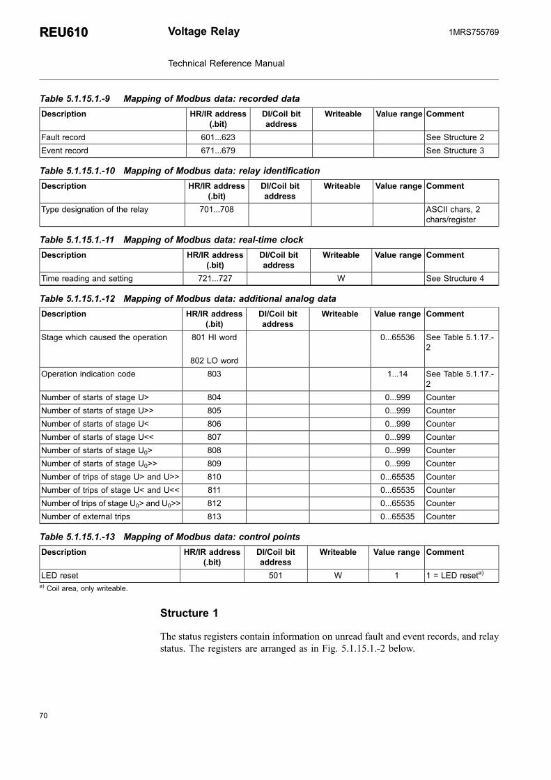
Table 5.1.15.1.-9 Mapping of Modbus data: recorded data
Description HR/IR address(.bit)
DI/Coil bitaddress
Writeable Value range Comment
Fault record 601...623 See Structure 2
Event record 671...679 See Structure 3
Table 5.1.15.1.-10 Mapping of Modbus data: relay identification
Description HR/IR address(.bit)
DI/Coil bitaddress
Writeable Value range Comment
Type designation of the relay 701...708 ASCII chars, 2chars/register
Table 5.1.15.1.-11 Mapping of Modbus data: real-time clock
Description HR/IR address(.bit)
DI/Coil bitaddress
Writeable Value range Comment
Time reading and setting 721...727 W See Structure 4
Table 5.1.15.1.-12 Mapping of Modbus data: additional analog data
Description HR/IR address(.bit)
DI/Coil bitaddress
Writeable Value range Comment
Stage which caused the operation 801 HI word 0...65536 See Table 5.1.17.-2
802 LO word
Operation indication code 803 1...14 See Table 5.1.17.-2
Number of starts of stage U> 804 0...999 Counter
Number of starts of stage U>> 805 0...999 Counter
Number of starts of stage U< 806 0...999 Counter
Number of starts of stage U<< 807 0...999 Counter
Number of starts of stage U0> 808 0...999 Counter
Number of starts of stage U0>> 809 0...999 Counter
Number of trips of stage U> and U>> 810 0...65535 Counter
Number of trips of stage U< and U<< 811 0...65535 Counter
Number of trips of stage U0> and U0>> 812 0...65535 Counter
Number of external trips 813 0...65535 Counter
Table 5.1.15.1.-13 Mapping of Modbus data: control points
Description HR/IR address(.bit)
DI/Coil bitaddress
Writeable Value range Comment
LED reset 501 W 1 1 = LED reseta)
a) Coil area, only writeable.
Structure 1
The status registers contain information on unread fault and event records, and relaystatus. The registers are arranged as in Fig. 5.1.15.1.-2 below.
70
REU610REU610 Voltage Relay
Technical Reference Manual
1MRS755769

71
��
��
��
�� � �
�&'&�7&-
@"�+(+!�, -&
9���, -&
�&'&�7&-�� �� �� =�
A040333
Fig. 5.1.15.1.-2 Status registers
When the value of the FR/ER bit is 1, there is one or several unread fault/eventrecords. If time synchronization is realized via a digital input, either the SP (second-pulse) or MP (minute-pulse) bit will be activated.
Refer to Table 5.1.18.-1 for IRF codes and Table 5.1.18.-2 for warning codes.
Structure 2
This structure contains data recorded during a fault sequence. Refer to Fault recordsearlier in this section for the reading method.
Table 5.1.15.1.-14 Fault record
Address Signal name Range Comment
601 Latest selection codea) 1...2 1 = read oldest unread record2 = read oldest stored record
602 Sequence number 1...255
603 Unread records left 0...6
604 Time stamp of the recorded data, date 2 bytes: YY.MM
605 Time stamp of the recorded data, date and time 2 bytes: DD.HH
606 Time stamp of the recorded data, time 2 bytes: MM.SS
607 Time stamp of the recorded data, time 0...999 0...999 ms
608 Phase-to-phase voltage U12 0...200 0...2 × Un
609 Phase-to-phase voltage U23 0...200 0...2 × Un
610 Phase-to-phase voltage U31 0...200 0...2 × Un
611 Residual voltage U0
0...200 0...200% Un
612 Maximum pickup phase-to-phase voltage 0...200 0...2 × Un
613 Minimum pickup phase-to-phase voltage 0...2000...2 × Un
614 Maximum pickup negative phase-sequence voltage U2s 0...2000...2 × Un
b)
615 Minimum pickup positive phase-sequence voltage U1s 0...200 0...2 × Unb)
616 Maximum residual voltage U0 0...200 0...200% Un
617 Start duration of stage U> 0...100 0...100%
618 Start duration of stage U>> 0...100 0...100%
619 Start duration of stage U< 0...100 0...100%
620 Start duration of stage U<< 0...100 0...100%
Voltage Relay
Technical Reference Manual
REU610REU6101MRS755769

Address Signal name Range Comment
621 Start duration of stage U0> 0...100 0...100%
622 Start duration of stage U0>> 0...100 0...100%
623 Start duration of external trip 0/100 0/100%a) Readable and writeable register.b) If not in use, the value 655 is returned.
Structure 3
This structure contains Modbus event records. Refer to Event records earlier in thissection for the reading method.
Table 5.1.15.1.-15 Event record
Address Signal name Range Comment
671 Latest selection codea) 1...3 1 = read oldest unread record2 = read oldest stored record3 = clear Modbus event buffer
-1...-99 -1...-99 = move to the nthnewest record
672 Sequence number 1...255
673 Unread records left 0...99
674 Time stamp of the event, date 2 bytes: YY.MM
675 Time stamp of the event, date and time 2 bytes: DD.HH
676 Time stamp of the event, time 2 bytes: MM.SS
677 Time stamp of the event, time 0...999 0...999 ms
678 Event data See Table 5.1.15.1.-16 forModbus DI-point events andTable 5.1.15.1.-17 forinformative events
679
a) Readable and writeable register.
Table 5.1.15.1.-16 Modbus DI-point event
Address Name Range Comment
678 0 Modbus DI-point 1...99 MSB = 0
679 Modbus DI value 0...1
Table 5.1.15.1.-17 Informative event
Address Name Range Comment
678 1 SPA channel 0...3 MSB = 1
679 SPA event 0...63
Structure 4
The relay's real-time clock is stored in this structure. It can be updated by presettingthe whole register structure in one Modbus transaction.
72
REU610REU610 Voltage Relay
Technical Reference Manual
1MRS755769

73
Table 5.1.15.1.-18 Real-time clock structure
Address Description Range
721 Year 0...99
722 Month 1...12
723 Day 1...31
724 Hour 0...23
725 Minute 0...59
726 Second 0...59
727 Hundredth of a second 0...99
5.1.16. DNP 3.0 remote communication protocol
The DNP 3.0 protocol was developed by Harris Control based on the early versionsof the IEC 60870-5 standard telecontrol protocol specifications. Today, the DNPprotocol specifications are controlled by the DNP Users Group.
The DNP protocol supports the ISO OSI (Open System Interconnection) basedmodel, which only specifies physical, data link and application layers. This reducedprotocol stack is referred to as Enhanced Performance Architecture (EPA). Tosupport advanced RTU functions and messages larger than the maximum framelength as defined in the IEC 60870-1, the DNP 3.0 Data Link is to be used with atransport pseudo-layer. As a minimum, the transport pseudo-layer implementsmessage assembly and disassembly services.
5.1.16.1. Protocol parameters
The DNP parameters can all be adjusted using Relay Setting Tool. For the DNPparameters, refer to Table 5.1.17.-13.
Storing DNP 3.0 parameters
All DNP parameters are stored on the external DNP 3.0 module. Afterparameterization with Relay Setting Tool, REU610 must be switched to the rearcommunication mode for at least 10 seconds in order for the DNP parameters to bereplicated and stored onto the DNP module. However, this is necessary only if theDNP parameters have been altered.
5.1.16.2. DNP 3.0 point list
The DNP data points (binary, analog and counters) of the relay, presented inTable 5.1.16.2.-1...Table 5.1.16.2.-3, are all in use as default.
The default class settings of the DNP points within the different event object groupsare:
Voltage Relay
Technical Reference Manual
REU610REU6101MRS755769

* Binary inputs change events: class 1* Analog inputs change events: class 2* Counter change events: class 3
All static data points belong to class 0.
Unsolicited reporting is enabled for all event objects as default. However, the point-specific enable/disable parameters are meaningless unless unsolicited reporting hasbeen enabled with SPA parameter 503V24.
The pointers to the scaling factors for analog objects are all 0 as default.Consequently, the DNP and Modbus analog values of the relay are identical asdefault.
All DNP process points can be edited using Relay Setting Tool. Editing featuresinclude:
* Re-organizing, adding and removing DNP points* Assigning event classes to specific DNP points* DNP point-specific enabling/disabling of unsolicited reporting* Defining deadbands for event reporting* Defining scaling factors for analog values
Table 5.1.16.2.-1 Binary data
Description DNP pointaddress
Event class UR enable Value range Comment
Start signal from stage U> 0 1 1 0/1 1 = activated
Trip signal from stage U> 1 1 1 0/1 1 = activated
Start signal from stage U>> 2 1 1 0/1 1 = activated
Trip signal from stage U>> 3 1 1 0/1 1 = activated
Start signal from stage U< 4 1 1 0/1 1 = activated
Trip signal from stage U< 5 1 1 0/1 1 = activated
Start signal from stage U<< 6 1 1 0/1 1 = activated
Trip signal from stage U<< 7 1 1 0/1 1 = activated
Start signal from stage U0> 8 1 1 0/1 1 = activated
Trip signal from stage U0> 9 1 1 0/1 1 = activated
Start signal from stage U0>> 10 1 1 0/1 1 = activated
Trip signal from stage U0>> 11 1 1 0/1 1 = activated
Trip lockout signal 12 1 1 0/1 1 = activated
External trip signal 13 1 1 0/1 1 = activated
CBFP 14 1 1 0/1 1 = failure
PO1 15 1 1 0/1 1 = activated
PO2 16 1 1 0/1 1 = activated
PO3 17 1 1 0/1 1 = activated
SO1 18 1 1 0/1 1 = activated
SO2 19 1 1 0/1 1 = activated
SO3 20 1 1 0/1 1 = activated
SO4 21 1 1 0/1 1 = activated
74
REU610REU610 Voltage Relay
Technical Reference Manual
1MRS755769

75
Description DNP pointaddress
Event class UR enable Value range Comment
SO5 22 1 1 0/1 1 = activated
DI1 23 1 1 0/1 1 = activated
DI2 24 1 1 0/1 1 = activated
DI3 25 1 1 0/1 1 = activated
DI4 26 1 1 0/1 1 = activated
DI5 27 1 1 0/1 1 = activated
Disturbance recorder 28 1 1 0/1 1 = triggered0 = cleared
HMI Setting password 29 1 1 0/1 1 = opened0 = closed
IRF 30 1 1 0/1 1 = activated
Warning 31 1 1 0/1 1 = activated
SPA event overflow 32 1 1 0/1 1 = activated
HMI Communication password 33 1 1 0/1 1 = opened0 = closed
Table 5.1.16.2.-2 Analog data
Description DNP pointaddress
Event class UR enable Deadband Value range Internalscaling
factor (ix = 0)
Phase-to-phase voltage U12 0 2 0 1 0...200 100
Phase-to-phase voltage U23 1 2 0 1 0...200 100
Phase-to-phase voltage U31 2 2 0 1 0...200 100
Residual voltage U0 3 2 0 1 0...200 100
Positive phase-sequence voltage 4 2 0 1 0...200 100
Negative phase-sequence voltage 5 2 0 1 0...200 100
Table 5.1.16.2.-3 Counters
Description DNP pointaddress
Event class UR enable Deadband Value range
Number of starts of stage U> 0 3 0 1 0...999
Number of starts of stage U>>/U2> 1 3 0 1 0...999
Number of starts of stage U< 2 3 0 1 0...999
Number of starts of stage U<</U1< 3 3 0 1 0...999
Number of starts of stage U0> 4 3 0 1 0...999
Number of starts of stage U0>> 5 3 0 1 0...999
Number of trips of stage U> and U>>/U2> 6 3 0 1 0...65535
Number of trips of stage U< and U<</U1< 7 3 0 1 0...65535
Number of trips of stage U0> and U0>> 8 3 0 1 0...65535
Number of external trips 9 3 0 1 0...65535
Voltage Relay
Technical Reference Manual
REU610REU6101MRS755769

5.1.16.3. DNP 3.0 device profile
DNP V3.00
DEVICE PROFILE DOCUMENT
Vendor Name: ABB Oy, Distribution Automation, Vaasa, Finland
Device Name: REU610
Highest DNP Level Supported Device Function
For Requests L2 Slave
For Responses L2
Notable objects, functions, and/or qualifiers supported in addition to the Highest DNP LevelsSupported (the complete list is described in the attached table):Additions to level 2 are marked as shaded in the implementation table
Maximum Data Link Frame Size (octets) Maximum Application Fragment Size (octets)
Transmitted 292 Transmitted 2048
Received 292 Received 2048
Maximum Data Link Re-tries: Maximum Application Layer Re-tries:
Configurable, range from 0 to 255 withprimary data link layer retransmission count
Configurable, range from 0 to 255 withapplication layer retransmission count
Requires Data Link Layer Confirmation:Configurable, with confirmation type selector, default NO ACK
Requires Application Layer Confirmation
Configurable with confirmation type selector when reporting Event Data (Slave devicesonly)
Always after response to reset request
Always when sending multi-fragment responses (Slave devices only)
Configurable, with confirmation type selector
Timeouts while waiting for:
Data Link Confirm Configurable with primary data link layertimeout, not relevant when NO ACK
Complete Appl. Fragment No, multi-fragment application frames notsupported
Application Confirm Configurable with application layer timeout
Complete Appl. Response No, not relevant in slave
Sends/Executes Control Operations
WRITE Binary Outputs Never
SELECT/OPERATE Never
DIRECT OPERATE Never
DIRECT OPERATE - NO ACK Never
Count Never
Code Never
Trip/Close Never
Pulse On Never
Queue Never
Clear Queue Never
FILL OUT THE FOLLOWING ITEMS FOR SLAVE DEVICES ONLY:
Reports Digital Input Change Events when nospecific variation requested
Reports time-tagged Digital Input ChangeEvents when no specific variation requested
76
REU610REU610 Voltage Relay
Technical Reference Manual
1MRS755769

77
Never Never
Only time-tagged Binary Input Change With Time
Only non-time-tagged Binary Input Change With Relative Time
Configurable to send both, one or the other(depends on default variation)
Configurable, depends on objects basicvariation (variation used at initialization)
Sends Unsolicited Responses Sends Static Data in Unsolicited Responses
Never Never
Configurable When Device Restarts
Only certain objects When Status Flags Change
Sometimes (attach explanation)
ENABLE/DISABLE UNSOLICITEDFunction codes supported
No other options are permitted.
Default Counter Object/Variation Counters Roll Over at
No Counters Reported No Counters Reported
Configurable, default object and variation Configurable (attach explanation)
Default Object 20Default Variation 2
16 Bits (Counters 6...9)
Point-by-point list attached 32 Bits, but roll-over bits not used
Other value: 999 (Counters 0...5) and 255(Counters 10...21)
Point-by-point list attached
Sends Multi-Fragment Responses Yes No
Table 5.1.16.3.-1 Supported function codes
Code Function Description Supported
Transfer Function Codes
0 Confirm Message fragment confirmationNo response
Yes
1 Read Request objects from outstationRespond with requested objects
Yes
2 Write Store specified objects to outstationRespond with status of operation
Yes
Control Function Codes
3 Select Select output point of outstationRespond with status of control point
No
4 Operate Set previously selected outputRespond with status of control point
No
5 Direct operate Set output directlyRespond with status of control point
No
6 Direct operate NO ACK Set output directlyNo response
No
Freeze Function Codes
7 Immediate Freeze Copy specified objects to freeze bufferRespond with status of operation
Yes
8 Immediate Freeze NO ACK Copy specified objects to freeze bufferNo response
Yes
Voltage Relay
Technical Reference Manual
REU610REU6101MRS755769

Code Function Description Supported
9 Freeze and Clear Copy specified objects to freeze buffer and clear objectsRespond with status of operation
Yesa)
10 Freeze and Clear NO ACK Copy specified objects to freeze buffer and clear objectsNo response
Yesa)
11 Freeze with time Copy specified objects to freeze buffer at specified timeRespond with status of operation
No
12 Freeze with time NO ACK Copy specified objects to freeze buffer at specified timeNo response
No
Application Control Function Codes
13 Cold Restart Perform desired reset sequenceRespond with a time object
Yes
14 Warm Restart Perform desired partial reset operationRespond with a time object
Yes
15 Initialize Data to Defaults Initialize the specified data to defaultRespond with status of operation
No
16 Initialize Application Set the specified application ready to be runRespond with status of operation
No
17 Start Application Start the specified application to runRespond with status of operation
Yes
18 Stop Application Stop the specified application to runRespond with status of operation
Yes
Configuration Function Codes
19 Save configuration Save configurationRespond with status of operation
No
20 Enable Unsolicited Messages Enable Unsolicited MessagesRespond with status of operation
Yes
21 Disable Unsolicited Messages Disable Unsolicited MessagesRespond with status of operation
Yes
22 Assign Class Assign specified objects to a classRespond with status of operation
Yes
Time Synchronization Function Codes
23 Delay Measurement Perform propagation delay measurement Yes
Response Function Codes
0 Confirm Message fragment confirmation Yes
129 Response Response to request message Yes
130 Unsolicited Message Spontaneous message without request Yesa) Counters of the relay cannot be cleared by using the DNP 3.0 protocol.
Table 5.1.16.3.-2 Supported objects
OBJECT REQUEST(slave must parse)
RESPONSE(master must parse)
Objectgroup
Variation Description Functioncodes (dec)
Qualifiercodes (hex)
Functioncodes (dec)
Qualifiercodes (hex)
1 0 Binary Input, all variations 1, 20, 21, 22 00, 01, 06, 07,08, 17, 28
129 00, 01, 17, 28
1 1 Binary Input 1, 20, 21, 22 00, 01, 06, 07,08, 17, 28
129 00, 01, 17, 28
1 2 Binary Input with Status 1, 20, 21, 22, 00, 01, 06, 07,08 17, 28
129 00, 01, 17, 28
78
REU610REU610 Voltage Relay
Technical Reference Manual
1MRS755769

79
OBJECT REQUEST(slave must parse)
RESPONSE(master must parse)
Objectgroup
Variation Description Functioncodes (dec)
Qualifiercodes (hex)
Functioncodes (dec)
Qualifiercodes (hex)
2 0 Binary Input Change, all variation 1 06, 07, 08
2 1 Binary Input Change without Time 1 06, 07, 08 129, 130 17, 28
2 2 Binary Input Change with Time 1 06, 07, 08 129, 130 17, 28
2 3 Binary Input Change with RelativeTime
10 0 Binary Output, all variations
10 1 Binary Output
10 2 Binary Output with Status
12 0 Control Block, all variations
12 1 Control Relay Output Block
12 2 Pattern Control Block
12 3 Pattern Mask
20 0 Binary Counter, all variations 1, 7, 8, 20, 21,22
00, 01, 06, 07,08, 17, 28
129 00, 01, 17, 28
20 1 32-Bit Binary Counter 1, 7, 8, 20, 21,22
00, 01, 06, 07,08, 17, 28
129 00, 01, 17, 28
20 2 16-Bit Binary Counter 1, 7, 8, 20, 21,22
00, 01, 06, 07,08, 17, 28
129 00, 01, 17, 28
20 3 32-Bit Delta Counter
20 4 16-Bit Delta Counter
20 5 32-Bit Binary Counter without Flag
20 6 16-Bit Binary Counter without Flag
20 7 32-Bit Delta Counter without Flag
20 8 16-Bit Delta Counter without Flag
21 0 Frozen Counter, all variations 1 00, 01, 06, 07,08, 17, 28
129 00, 01, 17, 28
21 1 32-Bit Frozen Counter 1 00, 01, 06, 07,08, 17, 28
129 00, 01, 17, 28
21 2 16-Bit Frozen Counter 1 00, 01, 06, 07,08, 17, 28
129 00, 01, 17, 28
21 3 32-Bit Frozen Delta Counter
21 4 16-Bit Frozen Delta Counter
21 5 32-Bit Frozen Counter with Time ofFreeze
1 00, 01, 06, 07,08, 17, 28
129 00, 01, 17, 28
21 6 16-Bit Frozen Counter with Time ofFreeze
1 00, 01, 06, 07,08, 17, 28
129 00, 01, 17, 28
21 7 32-Bit Frozen Delta Counter withTime of Freeze
21 8 16-Bit Frozen Delta Counter withTime of Freeze
21 9 32-Bit Frozen Counter without Flag
21 10 16-Bit Frozen Counter without Flag
21 11 32-Bit Frozen Delta Counterwithout Flag
Voltage Relay
Technical Reference Manual
REU610REU6101MRS755769

OBJECT REQUEST(slave must parse)
RESPONSE(master must parse)
Objectgroup
Variation Description Functioncodes (dec)
Qualifiercodes (hex)
Functioncodes (dec)
Qualifiercodes (hex)
21 12 16-Bit Frozen Delta Counterwithout Flag
22 0 Counter Change Event, allvariations
1 06, 07, 08 129, 130 17, 28
22 1 32-Bit Counter Change Eventwithout Time
1 06, 07, 08 129, 130 17, 28
22 2 16-Bit Counter Change Eventwithout Time
1 06, 07, 08 129, 130 17, 28
22 3 32-Bit Delta Counter Change Eventwithout Time
22 4 16-Bit Delta Counter Change Eventwithout Time
22 5 32-Bit Counter Change Event withTime
1 06, 07, 08 129, 130 17, 28
22 6 16-Bit Counter Change Event withTime
1 06, 07, 08 129, 130 17, 28
22 7 32-Bit Delta Counter Change Eventwith Time
22 8 16-Bit Delta Counter Change Eventwith Time
23 0 Frozen Counter Event, allvariations
23 1 32-Bit Frozen Counter Eventwithout Time
23 2 16-Bit Frozen Counter Eventwithout Time
23 3 32-Bit Frozen Delta Counter Eventwithout Time
23 4 16-Bit Frozen Delta Counter Eventwithout Time
23 5 32-Bit Frozen Counter Event withTime
23 6 16-Bit Frozen Counter Event withTime
23 7 32-Bit Frozen Delta Counter Eventwith Time
23 8 16-Bit Frozen Delta Counter Eventwith Time
30 0 Analog Input, all variations 1, 20, 21, 22 00, 01, 06, 07,08 17, 28
129 00, 01, 17, 28
30 1 32-Bit Analog Input 1, 20, 21, 22 00, 01, 06, 07,08 17, 28
129 00, 01, 17, 28
30 2 16-Bit Analog Input 1, 20, 21, 22 00, 01, 06, 07,08 17, 28
129 00, 01, 17, 28
30 3 32-Bit Analog Input without Flag 1, 20, 21, 22 00, 01, 06, 07,08 17, 28
129 00, 01, 17, 28
80
REU610REU610 Voltage Relay
Technical Reference Manual
1MRS755769

81
OBJECT REQUEST(slave must parse)
RESPONSE(master must parse)
Objectgroup
Variation Description Functioncodes (dec)
Qualifiercodes (hex)
Functioncodes (dec)
Qualifiercodes (hex)
30 4 16-Bit Analog Input without Flag 1, 20, 21, 22 00, 01, 06, 07,08 17, 28
129 00, 01, 17, 28
31 0 Frozen Analog Input, all variations
31 1 32-Bit Frozen Analog Input
31 2 16-Bit Frozen Analog Input
31 3 32-Bit Frozen Analog Input withTime of Freeze
31 4 16-Bit Frozen Analog Input withTime of Freeze
31 5 32-Bit Frozen Analog Input withoutFlag
31 6 16-Bit Frozen Analog Input withoutFlag
32 0 Analog Change Event, all variations 1 06, 07, 08 129, 130 17, 28
32 1 32-Bit Analog Change Eventwithout Time
1 06, 07, 08 129, 130 17, 28
32 2 16-Bit Analog Change Eventwithout Time
1 06, 07, 08 129, 130 17, 28
32 3 32-Bit Analog Change Event withTime
1 06, 07, 08 129, 130 17, 28
32 4 16-Bit Analog Change Event withTime
1 06, 07, 08 129, 130 17, 28
33 0 Frozen Analog Event, all variations
33 1 32-Bit Frozen Analog Event withoutTime
33 2 16-Bit Frozen Analog Event withoutTime
33 3 32-Bit Frozen Analog Event withTime
33 4 16-Bit Frozen Analog Event withTime
40 0 Analog Output Status, all variations
40 1 32-Bit Analog Output Status
40 2 16-Bit Analog Output Status
41 0 Analog Output Block, all variations
41 1 32-Bit Analog Output Block
41 2 16-Bit Analog Output Block
50 0 Time and Date, all variations 1 06, 07, 08 129 17, 28
50 1(def)
Time and Date 1 06, 07, 08 129 17, 28
50 1(def)
Time and Date 2 06, 07, 08 129
50 2 Time and Date with Interval
51 0 Time and Date CTO, all variations
51 1 Time and Date CTO
Voltage Relay
Technical Reference Manual
REU610REU6101MRS755769
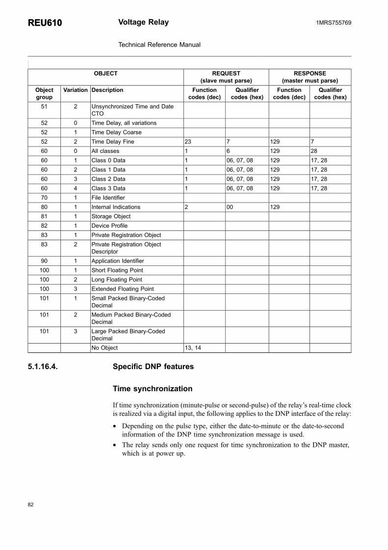
OBJECT REQUEST(slave must parse)
RESPONSE(master must parse)
Objectgroup
Variation Description Functioncodes (dec)
Qualifiercodes (hex)
Functioncodes (dec)
Qualifiercodes (hex)
51 2 Unsynchronized Time and DateCTO
52 0 Time Delay, all variations
52 1 Time Delay Coarse
52 2 Time Delay Fine 23 7 129 7
60 0 All classes 1 6 129 28
60 1 Class 0 Data 1 06, 07, 08 129 17, 28
60 2 Class 1 Data 1 06, 07, 08 129 17, 28
60 3 Class 2 Data 1 06, 07, 08 129 17, 28
60 4 Class 3 Data 1 06, 07, 08 129 17, 28
70 1 File Identifier
80 1 Internal Indications 2 00 129
81 1 Storage Object
82 1 Device Profile
83 1 Private Registration Object
83 2 Private Registration ObjectDescriptor
90 1 Application Identifier
100 1 Short Floating Point
100 2 Long Floating Point
100 3 Extended Floating Point
101 1 Small Packed Binary-CodedDecimal
101 2 Medium Packed Binary-CodedDecimal
101 3 Large Packed Binary-CodedDecimal
No Object 13, 14
5.1.16.4. Specific DNP features
Time synchronization
If time synchronization (minute-pulse or second-pulse) of the relay’s real-time clockis realized via a digital input, the following applies to the DNP interface of the relay:
* Depending on the pulse type, either the date-to-minute or the date-to-secondinformation of the DNP time synchronization message is used.
* The relay sends only one request for time synchronization to the DNP master,which is at power up.
82
REU610REU610 Voltage Relay
Technical Reference Manual
1MRS755769

83
Unsolicited reporting start up
Due to implementation differences in DNP master devices, the following alternativeunsolicited reporting (SPA parameter 503V24) start ups are available in the relay:
* 1 = Unsolicited reporting starts immediately, without permission from the master.* 2 = The relay sends an empty unsolicited response message when
communication begins, which the master confirms. After this, the relay starts tosend unsolicited responses.
* 3 = The relay sends an empty unsolicited response message whencommunication begins, which the master confirms. After this, the master enablesunsolicited reporting for certain or all classes using function 20. Classes whichare not enabled remain disabled.
Only the last alternative is compliant with the DNP 3.0 standard.
Event handling
The maximum capacity of the DNP event buffer is 100 events. When unsolicitedreporting has been enabled (SPA parameter 503V24), the event reporting uses thefollowing SPA parameters, called send throttle parameters:
503V18 Class 1 Event delay
503V19 Class 1 Event count
503V20 Class 2 Event delay
503V21 Class 2 Event count
503V22 Class 3 Event delay
503V23 Class 3 Event count
Example:
(class 1)
The events are reported when the event delay (SPA parameter 503V18) haselapsed or the defined amount of events (SPA parameter 503V19) aregenerated for class 1.
If send throttles are not wanted, the event delay should be set to 0 and theevent count to 1. In this case, the class events are sent to the host immediatelyas they occur.
Event buffer overflow
DNP 3.0 event buffer overflow is indicated with the internal indication IIN2.3, asdefined by the standard. IIN2.3 can also indicate event buffer overflow in theinternal communication between the DNP3.0 module and the main CPU module ofthe relay. In this case, the relay automatically activates and resets the IIN2.3 bit.
Voltage Relay
Technical Reference Manual
REU610REU6101MRS755769

As events have been lost in both cases, the DNP 3.0 master should perform anintegrity scan after the IIN2.3 bit has been reset.
DNP counters and frozen counters
DNP counters in use have a corresponding frozen counter. The frozen counters inobject group 21 have the same DNP point index as the ordinary DNP counters.Further, frozen counters can only be read as static objects, and frozen counter events(object group 23) are not supported.
Collision avoidance and detection
The relay supports both collision avoidance and detection. Collision detection canbe enabled or disabled with SPA parameter 503V235. Collision avoidance occursbefore message transmission. When preparing to transmit and the link is busy, therelay first waits until the link becomes idle. After this, a backoff time starts. Whenthe backoff time elapses, the relay checks the link again. If the link is not busy, therelay starts the transmission. The backoff time is calculated as follows:
backoff time = silent interval + random delay
The silent interval is set with SPA parameter 503V232 and the maximum randomdelay with SPA parameters 503V233 (the width of a single time slot inmilliseconds) and 503V234 (the maximum number of time slots). By setting thetime-slot width to 10 milliseconds and the maximum number of time slots to 10, forinstance, the maximum random delay is 100 milliseconds.
In a network consisting of several slaves, the priority between thedevices are defined with SPA parameters 503V233 and 503V234. Adevice with shorter silent interval and maximum random delay hashigher sending priority than a device with longer silent interval andmaximum random delay.
Collision detection is always active during transmission (provided that it has beenenabled). While sending a message, the relay supervises collisions on the link. If acollision is detected, the transmission is immediately cancelled. After this, the relaytries to transmit the message again, using collision avoidance before sending themessage.
Scaling DNP analog values
The DNP analog values can be scaled using either an internal (fixed) or a user-defined scaling factor. If the scaling factor index for a certain analog value is set to0, the internal scaling factor is used. If set to 1...5, the user-defined scaling factor ofthe corresponding scaling factor parameter, SPA parameter 503V (100+index), isused:
84
REU610REU610 Voltage Relay
Technical Reference Manual
1MRS755769

85
503V101 Scaling factor 1
503V102 Scaling factor 2
503V103 Scaling factor 3
503V104 Scaling factor 4
503V105 Scaling factor 5
Example:
Phase-to-phase voltage U12 0...2 × Un
Internal scaling factor 100
Default DNP range 0...200
To show the analog value in primary units, and if Un = 20000 V:
1. Take any unused scaling factor and set it to 20000.
2. Set the scaling index pointer of the analog value to point at the scaling factor.
3. The value range is now 0.00 × 20000...2.00 × 20000 = 0...20000 V.
DNP analog values deadband
The deadband is always defined in units of the original value when scaled using theinternal (fixed) scaling factor, irrespective of whether the internal scaling factor isused for value presentation or not.
Example:
For a deadband of 2% Un when the internal scaling factor is 100, thedeadband value is set as follows: 0.02 × 100 = 2. If the scaling factor is set to20 kV, the scaled deadband is 20 kV × 0.02 = 400 V
5.1.17. SPA bus communication protocol parameters
Altering parameter values via serial communication requires the use of the SPApassword in some cases. The password is a user-defined number within the range1...999, the default value being 001. SPA parameters are found on channels 0...5,503...504, 507 and 601...603.
To enter the setting mode, enter the password into parameter V160. To exit thesetting mode, enter the same password into parameter V161. The passwordprotection is also reactivated in case of loss of auxiliary voltage.
The password can be changed with parameter V162, but it is not possible to readthe password via this parameter. Abbreviations used in the following tables:
* R = readable data* W = writeable data* P = password protected writeable data
Voltage Relay
Technical Reference Manual
REU610REU6101MRS755769

Settings
Table 5.1.17.-1 Settings
Variable Actual settings (R),channel 0
Group/Channel 1(R, W, P)
Group/Channel 2(R, W, P)
Setting range
Start value of stage U> S1 1S1 2S1 0.60…1.40 × Un
Operate time of stage U> S2 1S2 2S2 0.06…600 s
IDMT operation mode setting forstage U>
S3 1S3 2S3 0…2
IDMT time multiplier k> S4 1S4 2S4 0.05…2.00
Resetting time of stage U> S5 1S5 2S5 0.07...60.0 s
Drop-off/pickup ratio D/P> S6 1S6 2S6 0.95…0.99
U1s/U2s mode setting of stages U>>and U<<
S7 1S7 2S7 0 = U>> and U<<1 = U>> and U1<2 = U2> and U<<
Start value of stage U>> S8a) 1S8 2S8 0.80…1.60 × Un
Start value of stage U2> S9a) 1S9 2S9 0.05…1.00 × Un
Operate time of stage U>> S10 1S10 2S10 0.05…600 s
IDMT operation mode setting forstage U>>
S11 1S11 2S11 0…2
IDMT time multiplier k>> S12 1S12 2S12 0.05…2.00
Start value of stage U< S13 1S13 2S13 0.20…1.20 × Un
Operate time of stage U< S14 1S14 2S14 0.10…600 s
IDMT operation mode setting forstage U<
S15 1S15 2S15 0…1
IDMT time multiplier k< S16 1S16 2S16 0.10…2.00
Resetting time of stage U< S17 1S17 2S17 0.07...60.0 s
Drop-off/pickup ratio D/P< S18 1S18 2S18 1.01…1.05
Start value of stage U<< S19a) 1S19 2S19 0.20…1.20 × Un
Start value of stage U1< S20a) 1S20 2S20 0.20...1.20× Un
Operate time of stage U<< S21 1S21 2S21 0.10...600 s
IDMT operation mode setting forstage U<<
S22 1S22 2S22 0…1
IDMT time multiplier k<< S23 1S23 2S23 0.10…2.00
Start value of stage U0> S24 1S24 2S24 2.0…80.0% Un
Operate time of stage U0> S25 1S25 2S25 0.10…600 s
Resetting time of stage U0> S26 1S26 2S26 0.07...60.0 s
Start value of stage U0>> S27a) 1S27 2S27 2.0…80.0% Un
Operate time of stage U0>> S28 1S28 2S28 0.10…600 s
Predefined time of CBFP S29 1S29 2S29 0.10…60.0 s
Checksum, SGF 1 S61 1S61 2S61 0…255
Checksum, SGF 2 S62 1S62 2S62 0…4095
Checksum, SGF 3 S63 1S63 2S63 0…15
Checksum, SGF 4 S64 1S64 2S64 0…1023
Checksum, SGF 5 S65 1S65 2S65 0…255
Checksum, SGB 1 S71 1S71 2S71 0…32767
86
REU610REU610 Voltage Relay
Technical Reference Manual
1MRS755769

87
Variable Actual settings (R),channel 0
Group/Channel 1(R, W, P)
Group/Channel 2(R, W, P)
Setting range
Checksum, SGB 2 S72 1S72 2S72 0…32767
Checksum, SGB 3 S73b) 1S73 2S73 0…32767
Checksum, SGB 4 S74b) 1S74 2S74 0…32767
Checksum, SGB 5 S75b) 1S75 2S75 0…32767
Checksum, SGR 1 S81 1S81 2S81 0…8191
Checksum, SGR 2 S82 1S82 2S82 0…8191
Checksum, SGR 3 S83 1S83 2S83 0…8191
Checksum, SGR 4 S84 1S84 2S84 0…8191
Checksum, SGR 5 S85 1S85 2S85 0…8191
Checksum, SGR 6 S86c) 1S86 2S86 0…8191
Checksum, SGR 7 S87c) 1S87 2S87 0…8191
Checksum, SGR 8 S88c) 1S88 2S88 0…8191
Checksum, SGL 1 S91 1S91 2S91 0...16383
Checksum, SGL 2 S92 1S92 2S92 0...16383
Checksum, SGL 3 S93 1S93 2S93 0...16383
Checksum, SGL 4 S94 1S94 2S94 0...16383
Checksum, SGL 5 S95 1S95 2S95 0...16383
Checksum, SGL 6 S96 1S96 2S96 0...16383
Checksum, SGL 7 S97 1S97 2S97 0...16383
Checksum, SGL 8 S98 1S98 2S98 0...16383a) If the protection stage is out of operation, the number indicating the currently used value will be displaced by “999” when the parameter is readvia the SPA bus and by dashes on the LCD.
b) If the optional I/O module has not been installed, a dash will be shown on the LCD and “99999” when the parameter is read via the SPA bus.c) If the optional I/O module has not been installed, a dash will be shown on the LCD and “9999” when the parameter is read via the SPA bus.
Recorded data
Parameter V1 shows the stage and phase which caused the trip or U< Alarm.Parameter V2 shows the trip indication code.
Parameters V3...V8 show the number of starts of the protection stages, parametersV9...V12 the number of trips of the protection stages.
Voltage Relay
Technical Reference Manual
REU610REU6101MRS755769

Table 5.1.17.-2 Recorded data: Channel 0
Recorded data Parameter (R) Value
Stage/phase which caused the trip V1 1 = U> (U31)2 = U> (U23)4 = U> (U12)8 = U0>16 = U>> (U31)32 = U>> (U23)64 = U>> (U12)128 = U0>>256 = U< (U31)512 = U< (U23)1024 = U< (U12)2048 = U<< (U31)4096 = U<< (U23)8192 = U<< (U12)16384 = U2s
32768 = U1s
65536 = External trip
Trip indication code V2 0 = - - -1 = U> Start2 = U> Trip3 = U>> Start4 = U>> Trip5 = U< Start6 = U< Trip7 = U<< Start8 = U<< Trip9 = U0> Start10 = U0> Trip11 = U0>> Start12 = U0>> Trip13 = External Trip14 = CBFP15 = U< Alarm
Number of starts of stage U> V3 0...999
Number of starts of stage U>> V4 0...999
Number of starts of stage U< V5 0...999
Number of starts of stage U<< V6 0...999
Number of starts of stage U0> V7 0...999
Number of starts of stage U0>> V8 0...999
Number of trips of stages U> and U>>/U2>
V9 0...65535
Number of trips of stages U< and U<</U1<
V10 0...65535
Number of trips of stages U0> and U0>> V11 0...65535
Number of external trips V12 0...65535
The last five recorded values can be read with parameters V1...V18 on channels1...5. Event n denotes the last recorded value, n-1 the next one, and so forth.
88
REU610REU610 Voltage Relay
Technical Reference Manual
1MRS755769

89
Table 5.1.17.-3 Recorded data: Channels 1...5
Recorded data Event (R) Value
n Channel 1 n-1 Channel 2 n-2 Channel 3 n-3 Channel 4 n-4 Channel 5
Phase-to-phasevoltage U12
1V1 2V1 3V1 4V1 5V1 0...2 × Un
Phase-to-phasevoltage U23
1V2 2V2 3V2 4V2 5V2 0...2 × Un
Phase-to-phasevoltage U31
1V3 2V3 3V3 4V3 5V3 0...2 × Un
Residual voltage U0 1V4 2V4 3V4 4V4 5V4 0…200% Un
Maximum pickupphase-to-phasevoltage
1V5 2V5 3V5 4V5 5V5 0...2 × Un
Minimum pickupphase-to-phasevoltage
1V6 2V6 3V6 4V6 5V6 0...2 × Un
Maximum pickupnegative phase-sequence voltage U2s
1V7 2V7 3V7 4V7 5V7 0...2 × Una)
Minimum pickuppositive phase-sequence voltage U1s
1V8 2V8 3V8 4V8 5V8 0...2 × Unb)
Maximum residualvoltage U0
1V9 2V9 3V9 4V9 5V9 0...200% Un
Start duration of stageU>
1V10 2V10 3V10 4V10 5V10 0…100%
Start duration of stageU>>
1V11 2V11 3V11 4V11 5V11 0…100%
Start duration of stageU<
1V12 2V12 3V12 4V12 5V12 0…100%
Start duration of stageU<<
1V13 2V13 3V13 4V13 5V13 0…100%
Start duration of stageU0>
1V14 2V14 3V14 4V14 5V14 0…100%
Start duration of stageU0>>
1V15 2V15 3V15 4V15 5V15 0…100%
Start duration ofexternal trip
1V16 2V16 3V16 4V16 5V16 0/100%
Time stamp of therecorded data, date
1V17 2V17 3V17 4V17 5V17 YY-MM-DD
Time stamp of therecorded data, time
1V18 2V18 3V18 4V18 5V18 HH.MM;SS.sss
a) If stage U>> is not based on negative phase-sequence voltage U2s, dashes are shown on the LCD and "999" when read via serialcommunication.
b) If stage U<< is not based on positive phase-sequence voltage U1s, dashes are shown on the LCD and "999" when read via serialcommunication.
Voltage Relay
Technical Reference Manual
REU610REU6101MRS755769

Disturbance recorder
Table 5.1.17.-4 Parameters for the disturbance recorder
Description Parameter (channel 0) R, W Value
Remote triggering M1a) W 1
Clear recorder memory M2 W 1
Sampling rate M15b) R, W 800/960 Hz400/480 Hz50/60 Hz
Station identification/unit number M18 R, W 0...9999
Rated frequency M19 R 50 or 60 Hz
Name of the station M20 R, W Max 16 characters
Digital channel texts M40...M47 R -
Analog channel texts M60...M63 R -
Analog channel conversion factor and unitfor primary voltage transformer(s)
M80c)d) R, W Factor 0.00...600, unit (V,kV), e.g. 20.0,kV
M81 and R
M82 R
Analog channel conversion factor and unitfor residual voltage U0
M83c) R, W Factor 0.00...600, unit (V,kV), e.g. 20.0,kV
Internal trigger signals' checksum V236 R, W 0...4095
Internal trigger signal's edge V237 R, W 0...4095
Checksum of internal signal storing mask V238b) R, W 0...4095
Post-triggering recording length V240 R, W 0...100%
External trigger signal's checksum V241 R, W 0...31
External trigger signal's edge V242 R, W 0...31
Checksum of external signal storing mask V243b) R, W 0...31
Triggering state, clearing and restart V246 R, W R:0 = Recorder not triggered1 = Recorder triggeredand recording stored inthe memoryW:0 = Clear recordermemory2 = Download restart; setsthe first information andthe time stamp fortriggering ready to be read4 = Manual triggering
a) M1 can be used for broadcast triggering by using the unit address “900”.b) Parameters can be written if the recorder has not been triggered.c) The disturbance recorder requires this parameter to be set. The conversion factor is the transformation ratio multiplied by the rated of therelay.If this parameter is set to zero, the disturbance recorder data cannot be analyzed and dashes are shown on the LCD instead of theprimary values.
d) This value is copied to parameters M81 and M82.
90
REU610REU610 Voltage Relay
Technical Reference Manual
1MRS755769

91
Table 5.1.17.-5 Disturbance recorder internal triggering and storing
Event Weightingfactor
Default value oftriggeringmask, V236
Default valueof triggeringedge, V237a)
Default value ofstoring mask,
V238
Start of stage U> 1 0 0 0
Trip of stage U> 2 1 0 1
Start of stage U>> orU2>
4 0 0 1
Trip of stage U>> orU2>
8 1 0 1
Start of stage U< 16 0 0 0
Trip of stage U< 32 1 0 1
Start of stage U<< orU1<
64 0 0 1
Trip of stage U<< orU1<
128 1 0 1
Start of stage U0> 256 0 0 0
Trip of stage U0> 512 1 0 1
Start of stage U0>> 1024 0 0 0
Trip of stage U0>> 2048 1 0 0
Σ 682 0 751a) 0 = rising edge; 1 = falling edge.
Table 5.1.17.-6 Disturbance recorder external triggering and storing
Event Weighting factor Default value oftriggering mask,
V241
Default value oftriggering edge,
V242a)
Default value ofstoring mask,
V243
DI1 1 0 0 0
DI2 2 0 0 0
DI3 4 0 0 0
DI4 8 0 0 0
DI5 16 0 0 0
Σ 0 0 0a) 0 = rising edge; 1 = falling edge.
Table 5.1.17.-7 Control parameters
Description Parameter R, W, P Value
Reading of the event buffer L R Time, channel number and event code
Re-reading of the event buffer B R Time, channel number and event code
Reading of relay state data C R 0 = Normal state1 = The relay has been subject to anautomatic reset2 = Overflow of the event buffer3 = Both 1 and 2
Resetting of relay state data C W 0 = Reset E50 and E511 = Reset only E502 = Reset only E514 = Reset all events including E51 except forE50
Time reading and setting T R, W SS.sss
Voltage Relay
Technical Reference Manual
REU610REU6101MRS755769

Description Parameter R, W, P Value
Date and time reading and setting D R, W YY-MM-DD HH.MM;SS.sss
Type designation of the relay F R REU610
Unlatching output contacts V101 W 1 = Unlatch
Clearing indications and memorized values andunlatching contacts (master reset)
V102 W 1 = Clear and unlatch
Resetting of trip lockout V103 W 1 = Reset
Rated frequency V104 R, W (P) 50 or 60 Hz
Time setting range for demand values inminutes
V105 R, W 0...999 min
Non-volatile memory settings V106 R, W 0...31
Time setting for disabling new trip indications onthe LCD
V108 R, W (P) 0...999 min
Testing the self-supervision V109 W (P) 1 = Self-supervision output contact isactivated and the READY indicator LEDstarts to blink0 = Normal operation
LED test for start and trip indicators V110 W (P) 0 = Start and trip LEDs off1 = Trip LED on, start LED off2 = Start LED on, trip LED off3 = Start and trip LEDs on
LED test for programmable LEDs V111 W (P) 0...255
Trip-circuit supervision V113 R, W 0 = Not in use1 = In use
Store countera) V114 R 0...65535
Nominal voltage V134 R, W (P) 0 = 100 V1 = 110 V2 = 115 V3 = 120 V
Remote control of setting group V150 R, W 0 = Setting group 11 = Setting group 2
Event mask for E31...E34 V155 R, W 0...63
Event mask for 1E1...1E16 1V155 R, W 0...65535
Event mask for 1E17…1E24 1V156 R, W 0...255
Event mask for 1E25…1E30 1V157 R, W 0...63
Event mask for 2E1...2E16 2V155 R, W 0...65535
Event mask for 2E17...2E26 2V156 R, W 0...1023
Entering the SPA password for settings V160 W 1...999
Changing the SPA password or taking thepassword protection into use
V161 W (P) 1...999
Changing the HMI Setting password V162 W 1...999
Changing the HMI Communication password V163 W 1...999
Clearing trip counters U> and U>>; U< and U<<;U0> and U0>>; External trips
V166 W (P) 1 = Clear trip counters
Restoring factory settings V167 W (P) 2 = Restore factory settings for CPU3 = Restore factory settings for DNP
Warning code V168 R 0...63b)
IRF code V169 R 0...255b)
Unit address of the relay V200 R, W 1...254
92
REU610REU610 Voltage Relay
Technical Reference Manual
1MRS755769

93
Description Parameter R, W, P Value
Data transfer rate (SPA), kbps V201 R, W 9.6/4.8
Rear communication V202 W 1 = Rear connector activated
Rear communication protocol V203c) R, W 0 = SPA1 = IEC_1032 = Modbus RTU3 = Modbus ASCII4 = DNP 3.0 (read-only)
Connection type V204 R, W 0 = Loop1 = Star
Line-idle state V205 R, W 0 = Light off1 = Light on
Optional communication module V206 R, W (P) 0 = Not in use1 = In used)
HMI language set information V226 R 00...99
CPU software number V227 R 1MRS118513
CPU software revision V228 R A...Z
CPU build number V229 R XXX
DNP protocol name 2V226 R DNP 3.0
DNP software number 2V227 R 1MRS118531
DNP software revision 2V228 R A...Z
DNP build number 2V229 R XXX
Relay serial number V230 R BAxxxxxx
CPU serial number V231 R ACxxxxxx
DNP serial number V232 R AKxxxxxx
Test date V235 R YYMMDD
Date reading and setting V250 R, W YY-MM-DD
Time reading and setting V251 R, W HH.MM;SS.sssa) The store counter can be used for monitoring parameter changes, for instance. The store counter is incremented by one on each parameterchange via the HMI or serial communication. When the counter reaches its maximum value, it will roll over. If the factory settings are restored,the counter is cleared.
b) In case of a warning, the value 255 is stored in V169. This enables the master to continuously read only V169.c) If the optional DNP 3.0 module has been installed, the DNP 3.0 communication protocol is automatically selected.d) If the optional communication module is not installed, a warning of a faulty communication module appears on the LCD together with the faultcode.
The measured voltages can be read with parameters I1...I4, the positive phase-sequence voltage with parameter I5, the negative phase-sequence voltage withparameter I6 and the status of the digital inputs with parameters I7...I11.
Table 5.1.17.-8 Input signals
Description Channel Parameter (R) Value
Measured phase-to-phase voltage U12 0 I1 0...2 × Un
Measured phase-to-phase voltage U23 0 I2 0...2 × Un
Measured phase-to-phase voltage U31 0 I3 0...2 × Un
Measured phase-to-phase voltage U0 0 I4 0...200% Un
Calculated positive phase-sequencevoltage
0 I5 0...2 × Un
Calculated negative phase-sequencevoltage
0 I6 0...2 × Un
Voltage Relay
Technical Reference Manual
REU610REU6101MRS755769

Description Channel Parameter (R) Value
DI1 status 0,2 I7 0/2a)
DI2 status 0,2 I8 0/2a)
DI3 status 0,2 I9 0/2a)b)
DI4 status 0,2 I10 0/2a)b)
DI5 status 0,2 I11 0/2a)b)
a) When the value is 1, the digital input is energized.b) If the optional I/O module has not been installed, a dash is shown on the LCD and "9" when theparameter is read via the SPA bus.
Each protection stage has its internal output signal. These signals can be read withparameters O1...O15 and the recorded functions with parameters O61...O75. Thestate of the output contacts can be read or changed with parameters O41...O49 andthe recorded functions read with parameters O101...O109.
Table 5.1.17.-9 Output signals
Status of theprotectionstages
Channel State of stage(R)
Recordedfunctions (R)
Value
Start of stageU>
0,1 O1 O61 0/1
Trip of stage U> 0,1 O2 O62 0/1
Start of U>> orU2>
0,1 O3 O63 0/1
Trip of stageU>> or U2>
0,1 O4 O64 0/1
Start of stage U< 0,1 O5 O65 0/1
Trip of stage U< 0,1 O6 O66 0/1 ;
Start of stageU<< or U1<
0,1 O7 O67 0/1
Trip of stage 0,1 O8 O68 0/1
Start of stageU0>
0,1 O9 O69 0/1
Trip of stage U0> 0,1 O10 O70 0/1
Start of stageU0>>
0,1 O11 O71 0/1
Trip of stageU0>>
0,1 O12 O72 0/1
External trip 0,1 O13 O73 0/1
Trip lockout 0,1 O14 O74 0/1
CBFP trip 0,1 O15 O75 0/1
94
REU610REU610 Voltage Relay
Technical Reference Manual
1MRS755769

95
Table 5.1.17.-10 Outputs
Operation ofoutputcontact
Channel State ofoutput (R, W,
P)
Recordedfunctions (R)
Value
Output PO1 0,2 O41 O101 0/1
Output PO2 0,2 O42 O102 0/1
Output PO3a) 0,2 O43 O103 0/1b)
Output SO1 0,2 O44 O104 0/1
Output SO2 0,2 O45 O105 0/1
Output PO3(trip lockout)c)
0,2 O46 - 0/1b)
Output SO3 0,2 O47 O107 0/1d)
Output SO4 0,2 O48 O108 0/1d)
Output SO5 0,2 O49 O109 0/1d)
Enablingactivation ofoutputcontacts PO1,PO2, PO3,SO1, SO2,SO3, SO4 andSO5 via theSPA bus
0,2 O51 - 0/1
a) State of output when the trip lockout function is not in use.b) Either O43/O103 or O46 is to be used at a time.c) State of output when the trip lockout function is in use.d) If the optional I/O module has not been installed, a dash is shown on the LCD and “9” when theparameter is read via the SPA bus.
Parameters O41...O49 and O51 control the physical output contactswhich can be connected to circuit breakers, for instance.
Parameters for IEC 60870-5-103 remote communication protocol
Table 5.1.17.-11 Settings
Description Parameter(channel 507)
R, W, P Value
Unit address of the relay 507V200 R, W 1...254
Data transfer rate (IEC 60870-5-103), kbps
507V201 R, W (P) 9.6/4.8
Voltage Relay
Technical Reference Manual
REU610REU6101MRS755769

Parameters for Modbus remote communication protocol
Table 5.1.17.-12 Settings
Description Parameter(channel 504)
R, W, P Value
User-defined register 1 504V1 R, W 0...65535a)
User-defined register 2 504V2 R, W 0...65535a)
User-defined register 3 504V3 R, W 0...65535a)
User-defined register 4 504V4 R, W 0...65535a)
User-defined register 5 504V5 R, W 0...65535a)
User-defined register 6 504V6 R, W 0...65535a)
User-defined register 7 504V7 R, W 0...65535a)
User-defined register 8 504V8 R, W 0...65535a)
User-defined register 9 504V9 R, W 0...65535a)
User-defined register 10 504V10 R, W 0...65535a)
User-defined register 11 504V11 R, W 0...65535a)
User-defined register 12 504V12 R, W 0...65535a)
User-defined register 13 504V13 R, W 0...65535a)
User-defined register 14 504V14 R, W 0...65535a)
User-defined register 15 504V15 R, W 0...65535a)
User-defined register 16 504V16 R, W 0...65535a)
Unit address of the relay 504V200 R, W 1...254
Data transfer rate (Modbus),kbps
504V201 R, W 9.6/4.8/2.4/1.2/0.3
Modbus link parity 504V220 R, W 0 = even1 = odd2 = no parity
CRC order of Modbus RTU link 504V221 R, W 0 = low/high1 = high/low
a) The default value is 0.
96
REU610REU610 Voltage Relay
Technical Reference Manual
1MRS755769

97
Parameters for DNP 3.0 remote communication protocol
Table 5.1.17.-13 Settings
Description SPAparameter
(channel 503)
R, W Value range Default Explanation
Unit address 503V1 R, W 0...65532 1 Address of the relay in the DNP 3.0network
Master address 503V2 R, W 0...65532 2 Address of the master station (destinationaddress for unsolicited responses)
Primary data link timeout 503V3 R, W 0 = no data linktimeout used1...65535 ms
0 Used when the relay sends data usingservice 3
Primary data link layerretransmission count
503V4 R, W 0...255 0 Number of retransmissions on data linklayer
Application layerconfirmation timeout
503V6 R, W 0...65535 ms 5000 Used when the relay sends messageswith confirmation request
Application layerretransmission count
503V7 R, W 0...255 0 Number of retransmissions on theapplication layer when the relay sendsmessages with confirmation request
Confirmation on applicationlayer
503V9 R, W 0 = enabled onlyfor eventmessages1 = enabled for allmessages
0 Used to enforce inclusion of confirmationrequest in all application messages(DNP 3.0 standard requires inclusion ofconfirmation request in event messagesonly)
Default variation of binaryinput objects
503V10 R, W 1...2 2
Default variation of binaryinput change event objects
503V11 R, W 1...2 2
Default variation of analoginput objects
503V15 R, W 1...4 2
Default variation of analoginput change event objects
503V16 R, W 1...4 2
Default variation of counterobjects
503V13 R, W 1...2 2
Default variation of counterchange event objects
503V14 R, W 1, 2, 5, 6 2
Default variation of frozencounter objects
503V30 R, W 1, 2, 5, 6 2
Class 1 event delay 503V18 R, W 0...255 s 0
Class 1 event count 503V19 R, W 0...255 1
Class 2 event delay 503V20 R, W 0...255 s 0
Class 2 event count 503V21 R, W 0...255 1
Class 3 event delay 503V22 R, W 0...255 s 0
Class 3 event count 503V23 R, W 0...255 1
Unsolicited reporting mode 503V24 R, W 0 = UR disabled1 = immediate2 = empty UR3 = empty UR andenable UR
0 Refer to Unsolicited reporting start up inSection 5.1.16.4. Specific DNP features.
Voltage Relay
Technical Reference Manual
REU610REU6101MRS755769

Description SPAparameter
(channel 503)
R, W Value range Default Explanation
Scaling factor 1 503V101 R, W 0...4294967295 1
Scaling factor 2 503V102 R, W 0...4294967295 1
Scaling factor 3 503V103 R, W 0...4294967295 1
Scaling factor 4 503V104 R, W 0...4294967295 1
Scaling factor 5 503V105 R, W 0...4294967295 1
Baud rate 503V211 R, W 4.8/9.6/19.2/38.4 9.6
Number of stop bits 503V212 R, W 1...2 1
Parity 503V230 R, W 0 = no parity1 = odd2 = even
0
Silent interval 503V232 R, W 0...65535 ms 20
Time slot width 503V233 R, W 0...255 ms 10
Number of time slots 503V234 R, W 0...255 8
Collision detection enabled 503V235 R, W 0 = disabled1 = enabled
0
DNP module warningregister
503V168 R Bit coded0 = OK
DNP module statusregister
503V169 R Bit coded0 = OK
Measurements
Table 5.1.17.-14 Measured values
Description Parameter(channel 0)
R, W, P Value
One-minute average voltage value V61 R 0...2 × Una)
Average voltage value during the specifiedtime range
V62 R 0...2 × Una)
Maximum one-minute average voltagevalue during the specified time range
V63 R 0...2 × Una)
Maximum voltage of the three phase-to-phase voltages since last reset
V64 R 0...2 × Un
Date of maximum voltage V65 R YY-MM-DD
Time of maximum voltage V66 R hh.mm;ss.sss
Minimum voltage of three phase-to-phasevoltages since last reset
V67 R 0...2 × Un
Date of minimum voltage V68 R YY-MM-DD
Time of minimum voltage V69 R hh.mm;ss.sssa) If the demand value is reset and the specified time has not elapsed, dashes are shown on the LCD and“999” when the parameter is read via the SPA bus.
5.1.17.1. Event codes
Special codes are determined to represent certain events, such as start and trippingof protection stages and different states of output signals.
98
REU610REU610 Voltage Relay
Technical Reference Manual
1MRS755769

99
The events are stored in the event buffer of the relay. The maximum capacity of thebuffer is 100 events. Under normal conditions the buffer is empty.
The contents of the buffer can be read using the L command, 5 events at a time.Using the L command erases the previously read events from the buffer, with theexception of events E50 and E51 which have to be reset by using the C command. Ifa fault occurs and reading fails for example in data communication, the events canbe re-read by using the B command. If needed, the B command can also be repeated.
The L and B commands are only available on channel 0.
Events to be included in the event reporting are marked with the multiplier 1. Theevent mask is formed by the sum of the weighting factors of all those events whichare to be included in event reporting.
Table 5.1.17.1.-1 Event masks
Event mask Code Setting range Default setting
V155 E31...E36 0...63 1
1V155 1E1...1E16 0...65535 21845
1V156 1E17...1E24 0...255 85
1V157 1E25...1E30 0...63 1
2V155 2E1...2E16 0...65535 3
2V156 2E17...2E26 0...1023 0
Channel 0
Events always included in the event reporting:
Table 5.1.17.1.-2 Event codes E1...E4
Channel Event Description
0 E1 IRF
0 E2 IRF disappeared
0 E3 Warning
0 E4 Warning disappeared
Table 5.1.17.1.-3 Event codes E50...E51
Channel Event Description
0 E50 Relay restart
0 E51 Event buffer overflow
Events possible to mask out:
Voltage Relay
Technical Reference Manual
REU610REU6101MRS755769

Table 5.1.17.1.-4 Event codes E31...E36
Channel Event Description Weightingfactor
Defaultvalue
0 E31 Disturbance recorder triggered 1 1
0 E32 Disturbance recorder memory cleared 2 0
0 E33 HMI Setting password opened 4 0
0 E34 HMI Setting password closed 8 0
0 E35 HMI Communication password opened 16 0
0 E36 HMI Communication password closed 32 0
Default value of event mask V155 1
Channel 1
Table 5.1.17.1.-5 Event codes E1...E16
Channel Event Description Weightingfactor
Defaultvalue
1 E1 Start signal from stage U> activated 1 1
1 E2 Start signal from stage U> reset 2 0
1 E3 Trip signal from stage U> activated 4 1
1 E4 Trip signal from stage U> reset 8 0
1 E5 Start signal from stage U>> or U2> activated 16 1
1 E6 Start signal from stage U>> or U2> reset 32 0
1 E7 Trip signal from stage U>> or U2> activated 64 1
1 E8 Trip signal from stage U>> or U2> reset 128 0
1 E9 Start signal from stage U< activated 256 1
1 E10 Start signal from stage U< reset 512 0
1 E11 Trip signal from stage U< activated 1024 1
1 E12 Trip signal from stage U< reset 2048 0
1 E13 Start signal from stage U<< or U1< activated 4096 1
1 E14 Start signal from stage U<< or U1< reset 8192 0
1 E15 Trip signal from stage U<< or U1< activated 16384 1
1 E16 Trip signal from stage U<< or U1< reset 32768 0
Default value of event mask 1V155 21845
Table 5.1.17.1.-6 Event codes E17...E24
Channel Event Description Weightingfactor
Defaultvalue
1 E17 Start signal from stage U0> activated 1 1
1 E18 Start signal from stage U0> reset 2 0
1 E19 Trip signal from stage U0> activated 4 1
1 E20 Trip signal from stage U0> reset 8 0
1 E21 Start signal from stage U0>> activated 16 1
1 E22 Start signal from stage U0>> reset 32 0
1 E23 Trip signal from stage U0>> activated 64 1
1 E24 Trip signal from stage U0>> reset 128 0
Default value of event mask 1V156 85
100
REU610REU610 Voltage Relay
Technical Reference Manual
1MRS755769

101
Table 5.1.17.1.-7 Event codes E25...E30
Channel Event Description Weightingfactor
Defaultvalue
1 E25 Trip lockout activated 1 1
1 E26 Trip lockout reset 2 0
1 E27 External trip activated 4 0
1 E28 External trip reset 8 0
1 E29 CBFP activated 16 0
1 E30 CBFP reset 32 0
Default value of event mask 1V157 1
Channel 2
Table 5.1.17.1.-8 Event codes E1...E16
Channel Event Description Weightingfactor
Defaultvalue
2 E1 PO1 activated 1 1
2 E2 PO1 reset 2 1
2 E3 PO2 activated 4 0
2 E4 PO2 reset 8 0
2 E5 PO3 activated 16 0
2 E6 PO3 reset 32 0
2 E7 SO1 activated 64 0
2 E8 SO1 reset 128 0
2 E9 SO2 activated 256 0
2 E10 SO2 reset 512 0
2 E11 SO3 activated 1024 0
2 E12 SO3 reset 2048 0
2 E13 SO4 activated 4096 0
2 E14 SO4 reset 8192 0
2 E15 SO5 activated 16384 0
2 E16 SO5 reset 32768 0
Default value of event mask 2V155 3
Table 5.1.17.1.-9 Event codes E17...E26
Channel Event Description Weightingfactor
Defaultvalue
2 E17 DI1 activated 1 0
2 E18 DI1 deactivated 2 0
2 E19 DI2 activated 4 0
2 E20 DI2 deactivated 8 0
2 E21 DI3 activated 16 0
2 E22 DI3 deactivated 32 0
2 E23 DI4 activated 64 0
2 E24 DI4 deactivated 128 0
2 E25 DI5 activated 256 0
Voltage Relay
Technical Reference Manual
REU610REU6101MRS755769
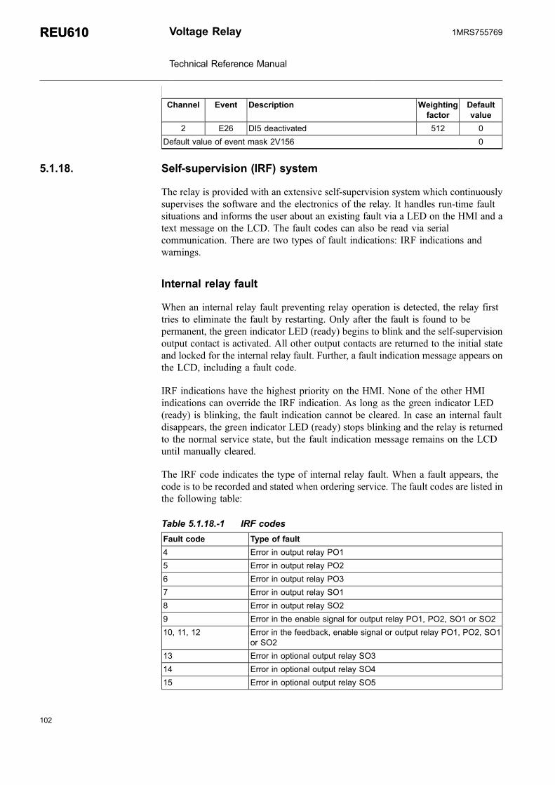
Channel Event Description Weightingfactor
Defaultvalue
2 E26 DI5 deactivated 512 0
Default value of event mask 2V156 0
5.1.18. Self-supervision (IRF) system
The relay is provided with an extensive self-supervision system which continuouslysupervises the software and the electronics of the relay. It handles run-time faultsituations and informs the user about an existing fault via a LED on the HMI and atext message on the LCD. The fault codes can also be read via serialcommunication. There are two types of fault indications: IRF indications andwarnings.
Internal relay fault
When an internal relay fault preventing relay operation is detected, the relay firsttries to eliminate the fault by restarting. Only after the fault is found to bepermanent, the green indicator LED (ready) begins to blink and the self-supervisionoutput contact is activated. All other output contacts are returned to the initial stateand locked for the internal relay fault. Further, a fault indication message appears onthe LCD, including a fault code.
IRF indications have the highest priority on the HMI. None of the other HMIindications can override the IRF indication. As long as the green indicator LED(ready) is blinking, the fault indication cannot be cleared. In case an internal faultdisappears, the green indicator LED (ready) stops blinking and the relay is returnedto the normal service state, but the fault indication message remains on the LCDuntil manually cleared.
The IRF code indicates the type of internal relay fault. When a fault appears, thecode is to be recorded and stated when ordering service. The fault codes are listed inthe following table:
Table 5.1.18.-1 IRF codes
Fault code Type of fault
4 Error in output relay PO1
5 Error in output relay PO2
6 Error in output relay PO3
7 Error in output relay SO1
8 Error in output relay SO2
9 Error in the enable signal for output relay PO1, PO2, SO1 or SO2
10, 11, 12 Error in the feedback, enable signal or output relay PO1, PO2, SO1or SO2
13 Error in optional output relay SO3
14 Error in optional output relay SO4
15 Error in optional output relay SO5
102
REU610REU610 Voltage Relay
Technical Reference Manual
1MRS755769

103
Fault code Type of fault
16 Error in the enable signal for optional output relay SO3, SO4 or SO5
17, 18, 19 Error in the feedback, enable signal or optional output relay SO3,SO4 or SO5
20, 21 Auxiliary voltage dip
30 Faulty program memory
50, 59 Faulty work memory
51, 52, 53a), 54, 56 Faulty parameter memoryb)
55 Faulty parameter memory, calibration parameters
80 Optional I/O module missing
81 Optional I/O module unknown
82 Optional I/O module configuration error
85 Power supply module faulty
86 Power supply module unknown
90 Hardware configuration error
95 Communication module unknown
104 Faulty configuration set (for IEC 60870-5-103)
131, 139, 195, 203,222, 223
Internal reference voltage error
253 Error in the measuring unita) Can be corrected by restoring factory settings for CPU.b) All settings will be zero during the fault.
For further information on internal relay faults, refer to the Operator’s Manual.
Warnings
In case of a warning, the relay continues to operate except for those protectionfunctions possibly affected by the fault, and the green indicator LED (ready)remains lit as during normal operation. Further, a fault indication message, whichdepending on the type of fault includes a fault code, appears on the LCD. If morethan one type of fault occur at the same time, one single numeric code whichindicates all the faults is displayed. The fault indication message cannot be manuallycleared but it disappears with the fault.
When a fault appears, the fault indication message is to be recorded and stated whenordering service. The fault codes are listed in the following table:
Table 5.1.18.-2 Warning codes
Fault Weight value
Battery low 1
Trip-circuit supervisiona) 2
Power supply module temperature high 4
Communication module faulty or missing 8
DNP 3.0 configuration errorb) 16
DNP 3.0 module faulty 32
∑ 63
Voltage Relay
Technical Reference Manual
REU610REU6101MRS755769

Table footnotes from previous page
a) The external fault warning can be routed to SO2 with SGF1/8.b) Can be corrected by restoring factory settings for DNP
For further information on warnings, refer to the Operator’s Manual.
5.1.19. Relay parameterization
The parameters of the relay can be set either locally via the HMI or externally viaserial communication with Relay Setting Tool.
Local parameterization
When the parameters are set locally, the setting parameters can be chosen via thehierarchical menu structure. The wanted language can be selected for parameterdescriptions. Refer to the Operator’s Manual for further information.
External parameterization
Relay Setting Tool is used for parameterizing the relay units. Adjusting theparameter values using Relay Setting Tool is done off-line, after which theparameters can be downloaded to the relay via a communication port.
5.2. Design description
5.2.1. Input/output connections
All external circuits are connected to the terminals on the rear panel of the relay.
* Terminals X2.1-_ are dimensioned for one 0.5...6.0 mm2 ( 20-8) wire or two max2.5 mm2 ( 24-12) wires
* Terminals X3.1-_ and X4.1-_ are dimensioned for one 0.2...2.5 mm2 wire or two0.2...1.0 mm2 ( 24-16) wires.
The energizing phase-to-phase voltages of the relay are connected to terminals:
* X2.1/1-2* X2.1/3-4* X2.1/5-6
For inputs for phase-to-phase voltages and residual voltage, refer to Table 5.2.1.-1.
The relay can also be used in single or two-phase applications byleaving one or two energizing inputs unoccupied. However, at leastterminals X2.1/1-2 must be connected.
104
REU610REU610 Voltage Relay
Technical Reference Manual
1MRS755769

105
The energizing residual voltage of the relay is connected to terminals X2.1/7-8, seeTable 5.2.1.-1.
The input terminals of the optional I/O module are located on connection socketX3.1, see Table 5.2.1.-4 and Table 5.2.1.-5.
When connection socket X3.1 is used, the optional I/O module must beinstalled.
The nominal voltage (100/110/115/120 V) of the matchingtransformers has to be selected with SPA parameter V134.
Terminals X4.1/21-24 and X3.1/1-6 (optional) are digital input terminals, seeTable 5.2.1.-5. The digital inputs can be used to generate a blocking signal, tounlatch output contacts or for remote control of relay settings, for instance. Therequested functions are selected separately for each input in switchgroups SGB1...5.The digital inputs can also be used to trigger the disturbance recorder; this functionis selected with SPA parameter V243.
The auxiliary voltage of the relay is connected to terminals X4.1/1-2, seeTable 5.2.1.-2. At DC supply, the positive lead is connected to terminal X4.1/1. Thepermitted auxiliary voltage range of the relay is marked on the front panel of therelay under the handle of the plug-in unit.
Output contacts PO1, PO2 and PO3 are heavy-duty trip contacts capable ofcontrolling most circuit breakers, see Table 5.2.1.-4.The signals to be routed toPO1...PO3 are selected with the switches of switchgroups SGR1...SGR3. Ondelivery from the factory, the trip signals from all the protection stages are routed toPO1, PO2 and PO3.
Output contacts SO1...SO5 can be used for signalling on start and tripping of therelay, see Table 5.2.1.-4.Output contacts SO3...SO5 are optional and available onlyif the optional I/O module has been installed. The signals to be routed to SO1...SO5are selected with the switches of switchgroups SGR4...SGR8. On delivery from thefactory, the start and alarm signals from all the protection stages are routed to SO1and SO2.
The IRF contact functions as an output contact for the self-supervision system of thevoltage relay, see Table 5.2.1.-3. Under normal operating conditions, the relay isenergized and the contact is closed (X4.1/3-5). When a fault is detected by the self-supervision system or the auxiliary voltage is disconnected, the output contact dropsoff and the contact closes (X4.1/3-4).
Fig. 5.2.1.-1...Fig. 5.2.1.-3 present a rear view of the relay, showing four connectingsockets: one for measuring transformers, one for the optional I/O module, one forpower supply and one for optional serial communication.
Voltage Relay
Technical Reference Manual
REU610REU6101MRS755769

�����������������������������������
�����������������������������������
��������
��������������
��������
��������
��������������
�������
������
�������
�����
��� ��� �
����
�������B��
��C��
���
�����
����
���C
�������
���
��
����
����
�����
D
.�
�
����
����
.�
�
A051555
Fig. 5.2.1.-1 Rear view of the relay with the fibre-optic communication module for plastic and glass fibre
106
REU610REU610 Voltage Relay
Technical Reference Manual
1MRS755769

107
�������B��
��C��
���
�����
����
���C
�������
���
��
����
����
�����
D
�����������������������������������
�����������������������������������
��������
��������������
��������
��������
��������������
�������
������
�������
�����
��� �
�� �
�� �
�� �
������
A040187
Fig. 5.2.1.-2 Rear view of the relay with the RS-485 communication module
Voltage Relay
Technical Reference Manual
REU610REU6101MRS755769

�����������������������������������
�����������������������������������
��������
��������������
��������
��������
��������������
�������
������
�������
�����
��� ��� �
����
�������B��
��C��
���
�����
����
���C
�������
���
��
����
����
�����
D
��
�������
A040189
Fig. 5.2.1.-3 Rear view of the relay with the DNP 3.0 communication module for RS-485
The wiring of Uab, Ubc, and Uca has to be done identically for each ofthe matching transformer used.
Table 5.2.1.-1 Inputs for phase-to-phase voltages and residual voltage
Terminal Function
REU610AVVxxxx
X2.1-1X2.1-2
U12
108
REU610REU610 Voltage Relay
Technical Reference Manual
1MRS755769

109
Terminal Function
REU610AVVxxxx
X2.1-3X2.1-4
U23
X2.1-5X2.1-6
U31
X2.1-7X2.1-8
U0
The wiring of U12, U23 and U31 has to be done identically for each ofthe matching transformer used.
Table 5.2.1.-2 Auxiliary supply voltage
Terminal Function
X4.1-1 Input, +
X4.1-2 Input, -
Table 5.2.1.-3 IRF contact
Terminal Function
X4.1-3 IRF, common
X4.1-4 Closed; IRF, or Uaux disconnected
X4.1-5 Closed; no IRF, and Uaux connected
Table 5.2.1.-4 Output contacts
Terminal Function
X3.1-16 SO5, commona)
X3.1-17 SO5, NCa)
X3.1-18 SO5, NOa)
X3.1-19 SO4, commona)
X3.1-20 SO4, NCa)
X3.1-21 SO4, NOa)
X3.1-22 SO3, commona)
X3.1-23 SO3, NCa)
X3.1-24 SO3, NOa)
X4.1-6 SO2, common
X4.1-7 SO2, NC
X4.1-8 SO2, NO
X4.1-9 SO1, common
X4.1-10 SO1, NC
X4.1-11 SO1, NO
X4.1-12 PO3 (trip lockout relay), NO
X4.1-13
X4.1-14 PO2, NO
Voltage Relay
Technical Reference Manual
REU610REU6101MRS755769

Terminal Function
X4.1-15
X4.1-16 PO1, NO
X4.1-17
X4.1-18 PO1 (TCS), NO
X4.1-19
X4.1-20 -a) Optional.
Table 5.2.1.-5 Digital inputs
Terminal Function
X4.1-23 DI1
X4.1-24
X4.1-21 DI2
X4.1-22
X3.1-1 DI3a)
X3.1-2
X3.1-3 DI4a)
X3.1-4
X3.1-5 DI5a)
X3.1-6a) Optional.
5.2.2. Serial communication connections
The optical front connection of the relay is used to connect the relay to the SPA busvia the front communication cable, refer to Section 6. Ordering information. If a PCcompatible to the IrDA® Standard specifications is used, wireless communication ispossible as well. The maximum wireless operating distance depends on thetransceiver of the PC.
Rear communication of the relay is optional and the physical connection varies withthe communication option.
Plastic fibre-optic connection
If the relay is provided with the optional fibre-optic communication module forplastic fibre, the fibre-optic cables are connected to terminals as follows:
Table 5.2.2.-1 Plastic fibre-optic rear connection
Terminal Function
X5.3-TX Transmitter
X5.3-RX Receiver
110
REU610REU610 Voltage Relay
Technical Reference Manual
1MRS755769

111
RS-485 connection
If the relay is provided with the optional RS-485 communication module, the cableis connected to terminals X5.5/1-2 and X5.5/4-6. The connection socket is a 6-pinheader-type socket and the terminals are of screw compression type.
The RS-485 communication module follows the TIA/EIA-485 standard and isintended to be used in a daisy-chain bus wiring scheme with 2-wire, half-duplex,multi-point communication.
The maximum number of devices (nodes) connected to the bus wherethe relay is being used is 32, and the maximum length of the bus is1200 meters.
When connecting the relay to the bus, a quality twisted pair shielded cable is to beused. The conductors of the pair are connected to A and B. If signal ground is beingused for balancing potential differences between devices/nodes, a quality dualtwisted pair shielded cable is to be used. In this case, one pair is connected to A andB, and one of the conductors of the other pair to signal ground. When connectingone device to another, A is connected to A and B to B.
The cable shield is to be connected directly to earth (shield GND) in one point/device of the bus. Other devices connected to the bus should have the cable shieldconnected to earth via a capacitor (shield GND via capacitor).
Signal ground can only be used for balancing potential differencesbetween devices/nodes if all devices connected to the bus have isolatedRS-485 interfaces.
The RS-485 communication module is provided with jumpers for setting bustermination and fail-safe biasing. The bus is to be terminated at both ends, whichcan be done by using the internal termination resistor on the communicationmodule. The termination resistor is selected by setting jumper X5 to the ONposition. If the internal termination resistor of 120 Ω is used, the impedance of thecable should be the same.
The bus is to be biased at one end to ensure fail-safe operation, which can be doneusing the pull-up and pull-down resistors on the communication module. The pull-up and pull-down resistors are selected by setting jumpers X3 and X4 to the ONposition.
The jumpers have been set to no termination (X5 in the OFF position) and nobiasing (X3 and X4 in the OFF position) as default.
Voltage Relay
Technical Reference Manual
REU610REU6101MRS755769

X3
X4
X5offon
offon
offon
A040334
Fig. 5.2.2.-1 Jumper location on the RS-485 communication module
Table 5.2.2.-2 RS-485 rear connector
Terminal Function
X5.5-6 Data A (+)
X5.5-5 Data B (-)
X5.5-4 Signal GND (for potential balancing)
X5.5-3 -
X5.5-2 Shield GND (via capacitor)
X5.5-1 Shield GND
Combined fibre-optic connection (plastic and glass)
If the relay is provided with the optional fibre-optic communication module forplastic and glass fibre, the plastic fibre-optic cables are connected to terminals X5.3-RX (Receiver) and X5.3-TX (Transmitter) and the glass fibre-optic cables toterminals X5.4-RX (Receiver) and X5.4-TX (Transmitter).
The fibre-optic interface is selected with jumpers X6 and X2 located on the PCB ofthe communication module (see Fig. 5.2.2.-2).
112
REU610REU610 Voltage Relay
Technical Reference Manual
1MRS755769
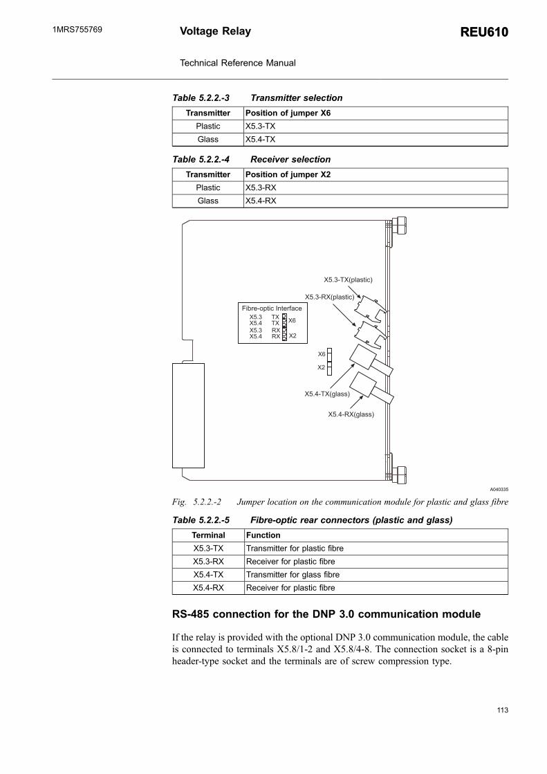
113
Table 5.2.2.-3 Transmitter selection
Transmitter Position of jumper X6
Plastic X5.3-TX
Glass X5.4-TX
Table 5.2.2.-4 Receiver selection
Transmitter Position of jumper X2
Plastic X5.3-RX
Glass X5.4-RX
��
��
��������
.�
.� ��
����������
� �
����% �B1,�22@
����%.�B1,�22@
�*E-3%+()*/�$")3-<�/3
����%.�B(,�2)*/@
����% �B(,�2)*/@
A040335
Fig. 5.2.2.-2 Jumper location on the communication module for plastic and glass fibre
Table 5.2.2.-5 Fibre-optic rear connectors (plastic and glass)
Terminal Function
X5.3-TX Transmitter for plastic fibre
X5.3-RX Receiver for plastic fibre
X5.4-TX Transmitter for glass fibre
X5.4-RX Receiver for plastic fibre
RS-485 connection for the DNP 3.0 communication module
If the relay is provided with the optional DNP 3.0 communication module, the cableis connected to terminals X5.8/1-2 and X5.8/4-8. The connection socket is a 8-pinheader-type socket and the terminals are of screw compression type.
Voltage Relay
Technical Reference Manual
REU610REU6101MRS755769

The DNP communication module follows the DNP standard and is intended to beused in a daisy-chain bus wiring scheme with 2- or 4-wire, half-duplex, multi-pointcommunication.
The maximum number of devices (nodes) connected to the bus wherethe relay is being used is 32, and the maximum length of the bus is1200 meters in optimum conditions and with slow communicationspeed.
When connecting the relay to the bus, a quality twisted pair shielded cable is to beused. The conductors of the pair are connected to A and B. If signal ground is beingused for balancing potential differences between devices/nodes, a quality dualtwisted pair shielded cable is to be used. In this case, one pair is connected to A andB, and one of the conductors of the other pair to signal ground. When connectingone device to another, A is connected to A and B to B.
When using a 4-wire bus, one pair is connected to +RX and -RX and the other to+TX and -TX. If signal ground is being used, a quality cable with three or severalpairs is to be used and one of the conductors of a pair connected to signal ground.
The cable shield is to be connected directly to earth (shield GND) in one point/device of the bus. Other devices connected to the bus should have the cable shieldconnected to earth via a capacitor (shield GND via capacitor).
Signal ground can only be used for balancing potential differencesbetween devices/nodes if all devices connected to the bus have isolatedDNP interfaces.
The DNP communication module is provided with jumpers for setting bustermination and fail-safe biasing. The bus is to be terminated at both ends, whichcan be done by using the internal termination resistor on the DNP communicationmodule. The termination resistor is selected by setting jumper X6 or/and X12 to theON position. If the internal termination resistor of 120Ω is used, the impedance ofthe cable should be the same.
The bus is to be biased at one end to ensure fail-safe operation, which can be doneusing the pull-up and pull-down resistors on the communication module. The pull-up and pull-down resistors are selected by setting jumpers X8, X7, X13 and X11 tothe ON position.
The 2-wire bus is selected by default (jumper X14) without termination or biasing.The jumpers X6, X7, X8 and X12 are in OFF position. The jumpers X11 and X13are in ON position.
114
REU610REU610 Voltage Relay
Technical Reference Manual
1MRS755769

115
Table 5.2.2.-6 RS-485 rear connector (DNP 3.0)
Terminal Function
X5.8-8 Data A (+ RX)
X5.8-7 Data B (- RX)
X5.8-6 Data A (+ TX)
X5.8-5 Data B (- TX)
X5.8-4 Signal GND (for potential balancing)
X5.8-3 -
X5.8-2 Shield GND (via capacitor)
X5.8-1 Shield GND
Table 5.2.2.-7 Jumper numbering
Terminal Function Signal
X8 Pull-up Data A (+ TX)
X6 Termination TX
X7 Pull-down Data B (- TX)
X13 Pull-up Data A (+ RX)
X12 Termination RX
X11 Pull-down Data B (- RX)
X14 4-wire/2-wire -
���
���
���
���
��
��
���!
�!
�!
�!
�!
�!
�%;*-3�%;*-3
A040357_2
Fig. 5.2.2.-3 Jumper location on the DNP 3.0 communication module
Voltage Relay
Technical Reference Manual
REU610REU6101MRS755769

5.2.3. Technical data
Table 5.2.3.-1 Dimensions (for dimension drawings, refer to the Installa-tion Manual)
Width, frame 177 mm, case 164 mm
Height, frame 177 mm (4U), case 160 mm
Depth, case 149.3 mm
Weight of the relay ~3.5 kg
Weight of the spare unit ~1.8 kg
Table 5.2.3.-2 Power supply
Uaux rated:
-REU610CVVHxxx Ur = 100/110/120/220/240 V ACUr = 110/125/220/250 V DC
-REU610CVVLxxx Ur = 24/48/60 V DC
Uaux variation (temporary):
-REU610CVVHxxx 85...110% of Ur (AC)80...120% of Ur (DC)
-REU610CVVLxxx 80...120% of Ur (DC)
Burden of auxiliary voltage supply under quiescent(Pq)/operating condition
<9 W/13 W
Ripple in the DC auxiliary voltage Max 12% of the DC value (atfrequency of 100 Hz)
Interruption time in the auxiliary DC voltage withoutresetting the relay
<50 ms at Uaux rated
Time to trip from switching on the auxiliary voltagea) <350 ms
Internal over temperature limit +100°C
Fuse type T2A/250 Va) Time to trip of stage U>>.
Table 5.2.3.-3 Energizing inputs
Rated frequency 50/60 Hz ±5 Hz
Rated voltage, Un 100/110/115/120 V
Thermal withstand capability:* continuously 2 × Un (240 V)* for 10 s 3 × Un (360 V)
Burden at rated voltage <0.5 VA
Table 5.2.3.-4 Measuring range
Measured phase-to-phase voltages U12, U23
and U31 as multiples of the rated voltages of theenergizing inputs
0...2 × Un
Measured residual voltage (U0) as a multiple ofthe rated voltage of the energizing input
0...2 × Un
116
REU610REU610 Voltage Relay
Technical Reference Manual
1MRS755769

117
Table 5.2.3.-5 Digital inputs
Rated voltage: DI1...DI2 DI3...DI5 (optional)
REU610CVVHxxx 110/125/220/250 V DC
Activating threshold Max. 88 V DC (110 V DC -20%)
REU610CVVLxxx 24/48/60/110/125/220/250 V DC
Activating threshold Max. 19,2 V DC (24 V DC -20%)
REU610CVVxxLx 24/48/60/110/125/220/250 V DC
Activating threshold Max. 19,2 V DC (24 V DC -20%)
REU610CVVxxHx 110/125/220/250 V DC
Activating threshold Max. 88 V DC (110 V DC -20%)
Operating range ±20% of the rated voltage
Current drain 2...18 mA
Power consumption/input ≤0.9 W
Table 5.2.3.-6 Signal output SO1 and optional SO4 and SO5
Rated voltage 250 V AC/DC
Continuous carry 5 A
Make and carry for 3.0 s 15 A
Make and carry for 0.5 s 30 A
Breaking capacity when the control-circuit time constantL/R <40 ms, at 48/110/220 V DC
1 A/0.25 A/0.15 A(5 A/3 A/1 A for series connectionof SO4 and SO5)
Minimum contact load 100 mA at 24 V AC/DC
Table 5.2.3.-7 Signal output SO2, optional SO3, and IRF output
Rated voltage 250 V AC/DC
Continuous carry 5 A
Make and carry for 3.0 s 10 A
Make and carry for 0.5 s 15 A
Breaking capacity when the control-circuit time constantL/R <40 ms, at 48/110/220 V DC
1 A/0.25 A/0.15 A
Minimum contact load 100 mA at 24 V AC/DC
Table 5.2.3.-8 Power outputs (PO1, PO2, PO3)
Rated voltage 250 V AC/DC
Continuous carry 5 A
Make and carry for 3.0 s 15 A
Make and carry for 0.5 s 30 A
Breaking capacity when the control-circuit time constant L/R <40 ms, at 48/110/220 V DC (PO1 with both contactsconnected in series)
5 A/3 A/1 A
Minimum contact load 100 mA at 24 V AC/DC
Trip-circuit supervision (TCS):* Control voltage range 20...265 V AC/DC
Voltage Relay
Technical Reference Manual
REU610REU6101MRS755769

* Current drain through the supervision circuit ~1.5 mA* Minimum voltage over a contact 20 V AC/DC (15...20 V)
Table 5.2.3.-9 Enclosure class of the flush-mounted relay
Front side IP 54 Category 2
Rear side, top of the relay IP 40
Rear side, connection terminals IP 20
Table 5.2.3.-10 Environmental tests and conditions
Recommended service temperature range (continuous) -10...+55°C
Humidity < 95% RH
Limit temperature range (short-term) -40...+70°C
Transport and storage temperature range -40...+85°C according toIEC 60068-2-48
Dry heat test (humidity <50%) According to IEC 60068-2-2
Dry cold test According to IEC 60068-2-1
Damp heat test, cyclic (humidity >93%) According to IEC 60068-2-30
Atmospheric pressure 86...106 kPa
Table 5.2.3.-11 Electromagnetic compatibility tests
EMC immunity test level meets the requirements listed below:
1 MHz burst disturbance test, class III According to IEC 60255-22-1, IEC 61000-4-18
* Common mode 2.5 kV* Differential mode 1.0 kV
Electrostatic discharge test, class IV According to IEC 61000-4-2, IEC 60255-22-2and ANSI C37.90.3-2001
* For contact discharge 8 kV* For air discharge 15 kV
Radio frequency interference tests:* Conducted, common mode According to IEC 61000-4-6 and IEC 60255-
22-6 (2000)10 V (rms), f = 150 kHz...80 MHz
* Radiated, amplitude-modulated According to IEC 61000-4-3 and IEC 60255-22-3 (2000)10 V/m (rms), f = 80...1000 MHz
* Radiated, pulse-modulated According to the ENV 50204 and IEC 60255-22-3 (2000)10 V/m, f = 900 MHz
Fast transient disturbance tests According to IEC 60255-22-4 and IEC 61000-4-4
* Power outputs, energizing inputs, powersupply
4 kV
* I/O ports 2 kV
Surge immunity test According to IEC 61000-4-5 and IEC 60255-22-5
* Power outputs, energizing inputs, powersupply
4 kV, line-to-earth2 kV, line-to-line
* I/O ports 2 kV, line-to-earth1 kV, line-to-line
118
REU610REU610 Voltage Relay
Technical Reference Manual
1MRS755769

119
Power frequency (50 Hz) magnetic fieldIEC 61000-4-8
300 A/m continuous
Power frequency immunity test: According to IEC 60255-22-7 and IEC 61000-4-16
REU610CVVHxxx and REU610CVVxxHx Class A* Common mode 300 V rms* Differential mode 150 V rms
REU610CVVLxxx and REU610CVVxxLx Class B* Common mode 300 V rms* Differential mode 100 V rms
Voltage dips and short interruptions According to IEC 61000-4-11
30%/10 ms
60%/100 ms
60%/1000 ms
>95%/5000 ms
Electromagnetic emission tests According to the EN 55011* Conducted, RF-emission (Mains terminal) EN 55011, class A, IEC 60255-25* Radiated RF-emission EN 55011, class A, IEC 60255-25
CE approval Complies with the EMC directive EMC 2004/108/EC and the LV directive LV 2006/95/EC
Table 5.2.3.-12 Standard tests
Insulation tests:
Dielectric tests According to IEC 60255-5* Test voltage 2 kV, 50 Hz, 1 min
Impulse voltage test According to IEC 60255-5* Test voltage 5 kV, unipolar impulses, waveform
1.2/50 μs, source energy 0.5 J
Insulation resistance measurements According to IEC 60255-5* Isolation resistance >100 MΩ, 500 V DC
Mechanical tests:
Vibration tests (sinusoidal) According to IEC 60255-21-1, class I
Shock and bump test According to IEC 60255-21-2, class I
Table 5.2.3.-13 Data communication
Rear interface:* Fibre-optic or RS-485 connection* SPA bus, IEC 60870-5-103, DNP 3.0 or Modbus protocol* 9.6 or 4.8 kbps (additionally 2.4, 1.2 or 0.3 kbps for Modbus)
Front interface:* Optical connection (infrared): wirelessly or via the front communication cable(1MRS050698)
* SPA bus protocol* 9.6 or 4.8 kbps (9.6 kbps with front communication cable)
Voltage Relay
Technical Reference Manual
REU610REU6101MRS755769
Optional communication modules and protocols
* SPA-bus, IEC 60870-5-103, Modbus® (RTU and ASCII):* Plastic fibre* Plastic and glass fibre* RS485
* DNP 3.0:* RS485 including DNP 3.0 protocol
Auxiliary voltage
The relay requires a secured auxiliary voltage supply to operate. The internal powersupply of the relay forms the voltages required by the relay electronics. The powersupply is a galvanically isolated (flyback-type) DC/DC converter. When theauxiliary voltage is connected, the green indicator LED (ready) on the front panel islit. For detailed information on power supply, refer to Table 5.2.3.-2.
The primary side of the power supply is protected with a fuse located on the printedcircuit board of the relay.
120
REU610REU610 Voltage Relay
Technical Reference Manual
1MRS755769

121
6. Ordering informationWhen ordering voltage relays and/or accessories, specify the following:
* Order number* HMI language set number* Quantity
The order number identifies the voltage relay type and hardware as described in thefigures below and is labelled on the marking strip under the lower handle of therelay.
Use the ordering key information in Fig. 6.-1 to generate the order number whenordering complete voltage relays.
Language set:01 = (IEC) English, Svenska, Suomi02 = (IEC) English, Deutsch, Francais, Italiano, Español, Polski03 = (IEC) English, Español, Português, Francais11 = (ANSI) English, Español, Português
REU610CVVHCNP 01
Communication module:P = plastic fiberG = plastic and glass fiberR = RS-485D = RS-485 including DNP 3.0 protocolN = none
I/O extension module:H = 3xSO and 3xDI (110/125/220/250 V DC)L = 3xSO and 3xDI (24/48/60/110/125/220/250 V DC)N = none
Power supply:H = 100-240 V AC/110-250 V DC, 2xDI (110/125/220/250 V DC), 3xPO 2xSOL = 24-60 V DC, 2xDI (24/48/60/110/125/220/250 V DC), 3xPO, 2xSO
Residual voltage input:V = rated voltages (100/110/115/120 V)
Phase-to-phase voltage inputs:V = rated voltages (100/110/115/120 V)
RevisionA052080_3
Fig. 6.-1 Ordering key for complete relays
Use the ordering key information in Fig. 6.-2 to generate the order number whenordering spare units.
Voltage Relay
Technical Reference Manual
REU610REU6101MRS755769

REU610CVVHSNS 01
I/O extension module:H = 3xSO and 3xDI (110/125/220/250 V DC)L = 3xSO and 3xDI (24/48/60/110/125/220/250 V DC)N = none
Power supply:H = 100-240 V AC/110-250 V DC, 2xDI (110/125/220/250 V DC), 3xPO 2xSOL = 24-60 V DC, 2xDI (24/48/60/110/125/220/250 V DC), 3xPO, 2xSO
Residual voltage input:V = rated voltages (100/110/115/120 V)
Phase-to-phase voltage inputs:V = rated voltages (100/110/115/120 V)
Language set:01 = (IEC) English, Svenska, Suomi02 = (IEC) English, Deutsch, Francais, Italiano, Español, Polski03 = (IEC) English, Español, Português, Francais11 = (ANSI) English, Español, Português
A052093_3
Fig. 6.-2 Ordering key for spare units
The following accessories are available:
Item Order number
Semi-flush mounting kit 1MRS050696
Inclined (/ 25º) semi-flush mounting kit 1MRS050831
Wall mounting kit 1MRS050697
19” Rack mounting kit, two relays side-by-side 1MRS050695
19" Rack mounting kit, single relay 1MRS050694
19" Rack mounting kit, single relay and RTXP18 (REU610) 1MRS090937
19" equipment frame mounting kit (Combiflex), single relayand RTXP18 (REU610)
1MRS090936
19" equipment frame mounting kit (Combiflex), single relay 1MRS050779
Front communication cable 1MRS050698
Communication modules:* Plastic fibre 1MRS050889* RS-485 1MRS050892* Plastic and glass fibre 1MRS050891* RS-485 including DNP 3.0 protocol 1MRS050887
122
REU610REU610 Voltage Relay
Technical Reference Manual
1MRS755769

123
7. Check lists
Table 7.-1 Setting group 1
Variable Group/Channel 1
(R, P)
Setting range Defaultsetting
Customer'ssetting
Start value of stage U> 1S1 0.60…1.40 × Un 1.2 × Un
Operate time of stage U> 1S2 0.06…600 s 0.06 s
IDMToperation mode setting forstage U>
1S3 0…2 0
IDMT time multiplier, k> 1S4 0.05…2.00 0.05
Resetting time of stage U> 1S5 0.07...60.0 s 0.07 s
Drop-off/pick-up ratio D/P> 1S6 0.95…0.99 0.97
U1s/U2s mode setting of stagesU>> and U<<
1S7 0...2 0
Start value of stage U>> 1S8 0.80…1.60 × Un 1.20 × Un
Start value of stage U2> 1S9 0.05…1.00 × Un 0.05 × Un
Operate time of stage U>> 1S10 0.05…600 s 0.05 s
IDMToperation mode setting forstage U>>
1S11 0…2 0
IDMT time multiplier, k>> 1S12 0.05…2.00 0.05
Start value of stage U< 1S13 0.20…1.20 × Un 0.20 × Un
Operate time of stage U< 1S14 0.10…600 s 0.10 s
IDMToperation mode setting forstage U<
1S15 0…1 0
IDMT time multiplier, k< 1S16 0.10…2.00 0.10
Resetting time of stage U< 1S17 0.07...60.0 s 0.07 s
Drop-off/pick-up ratio D/P< 1S18 1.01…1.05 1.03
Start value of stage U<< 1S19 0.20…1.20 × Un 0.20 × Un
Start value of stage U1< 1S20 0.20…1.20 × Un 0.20 × Un
Operate time of stage U<< 1S21 0.10…600 s 0.10 s
IDMToperation mode setting forstage U<<
1S22 0…1 0
IDMT time multiplier, k<< 1S23 0.10…2.00 0.10
Start value of stage U0> 1S24 2.0…80.0% Un 2.0% Un
Operate time of stage U0> 1S25 0.10…600 s 0.10 s
Resetting time of stage U0> 1S26 0.07...60.0 s 0.07s
Start value of stage U0>> 1S27 2.0…80.0% Un 2.0% Un
Operate time of stage U0>> 1S28 0.10…600 s 0.10 s
Predefined time of CBFP 1S29 0.10…60.0 s 0.10 s
Checksum, SGF1 1S61 0…255 0
Checksum, SGF2 1S62 0…4095 2730
Checksum, SGF3 1S63 0…15 0
Checksum, SGF4 1S64 0…1023 128
Checksum, SGF5 1S65 0…255 0
Checksum, SGB1 1S71 0…32767 0
Checksum, SGB2 1S72 0…32767 0
Voltage Relay
Technical Reference Manual
REU610REU6101MRS755769

Variable Group/Channel 1
(R, P)
Setting range Defaultsetting
Customer'ssetting
Checksum, SGB3 1S73 0…32767 0
Checksum, SGB4 1S74 0…32767 0
Checksum, SGB5 1S75 0…32767 0
Checksum, SGR1 1S81 0…8191 2730
Checksum, SGR2 1S82 0…8191 2730
Checksum, SGR3 1S83 0…8191 2730
Checksum, SGR4 1S84 0…8191 1365
Checksum, SGR5 1S85 0…8191 1365
Checksum, SGR6 1S86 0…8191 0
Checksum, SGR7 1S87 0…8191 0
Checksum, SGR8 1S88 0…8191 0
Checksum, SGL1 1S91 0…16383 0
Checksum, SGL2 1S92 0…16383 0
Checksum, SGL3 1S93 0…16383 0
Checksum, SGL4 1S94 0…16383 0
Checksum, SGL5 1S95 0…16383 0
Checksum, SGL6 1S96 0…16383 0
Checksum, SGL7 1S97 0…16383 0
Checksum, SGL8 1S98 0…16383 0
Table 7.-2 Setting group 2
Variable Group/Channel 2
(R, P)
Setting range Defaultsetting
Customer'ssetting
Start value of stage U> 2S1 0.60…1.40 × Un 1.2 × Un
Operate time of stage U> 2S2 0.06…600 s 0.06 s
IDMToperation mode setting forstage U>
2S3 0…2 0
IDMT time multiplier, k> 2S4 0.05…2.00 0.05
Resetting time of stage U> 2S5 0.07...60.0 s 0.07 s
Drop-off/pick-up ratio D/P> 2S6 0.95…0.99 0.97
U1s/U2s mode setting of stagesU>> and U<<
2S7 0...2 0
Start value of stage U>> 2S8 0.80…1.60 × Un 1.20× Un
Start value of stage U2> 2S9 0.05…1.00 × Un 0.05 × Un
Operate time of stage U>> 2S10 0.05…600 s 0.05 s
IDMToperation mode setting forstage U>>
2S11 0…2 0
IDMT time multiplier, k>> 2S12 0.05…2.00 0.05
Start value of stage U< 2S13 0.20…1.20 × Un 0.20 × Un
Operate time of stage U< 2S14 0.10…600 s 0.10 s
IDMToperation mode setting forstage U<
2S15 0…1 0
IDMT time multiplier, k< 2S16 0.10…2.00 0.10
124
REU610REU610 Voltage Relay
Technical Reference Manual
1MRS755769

125
Variable Group/Channel 2
(R, P)
Setting range Defaultsetting
Customer'ssetting
Resetting time of stage U< 2S17 0.07...60.0 s 0.07 s
Drop-off/pick-up ratio D/P< 2S18 1.01…1.05 1.03
Start value of stage U<< 2S19 0.20…1.20 × Un 0.20 × Un
Start value of stage U1< 2S20 0.20…1.20 × Un 0.20 × Un
Operate time of stage U<< 2S21 0.10…600 s 0.10 s
IDMToperation mode setting forstage U<<
2S22 0…1 0
IDMT time multiplier, k<< 2S23 0.10…2.00 0.10
Start value of stage U0> 2S24 2.0…80.0% Un 2.0% Un
Operate time of stage U0> 2S25 0.10…600 s 0.10 s
Resetting time of stage U0> 2S26 0.07...60.0 s 0.07 s
Start value of stage U0>> 2S27 2.0…80.0% Un 2.0% Un
Operate time of stage U0>> 2S28 0.10…600 s 0.10 s
Predefined time of CBFP 2S29 0.10…60.0 s 0.10 s
Checksum, SGF1 2S61 0…255 0
Checksum, SGF2 2S62 0…4095 2730
Checksum, SGF3 2S63 0…15 0
Checksum, SGF4 2S64 0...1023 128
Checksum, SGF5 2S65 0…255 0
Checksum, SGB1 2S71 0…32767 0
Checksum, SGB2 2S72 0…32767 0
Checksum, SGB3 2S73 0…32767 0
Checksum, SGB4 2S74 0…32767 0
Checksum, SGB5 2S75 0…32767 0
Checksum, SGR1 2S81 0…8191 2730
Checksum, SGR2 2S82 0…8191 2730
Checksum, SGR3 2S83 0…8191 2730
Checksum, SGR4 2S84 0…8191 1365
Checksum, SGR5 2S85 0…8191 1365
Checksum, SGR6 2S86 0…8191 0
Checksum, SGR7 2S87 0…8191 0
Checksum, SGR8 2S88 0…8191 0
Checksum, SGL1 2S91 0…16383 0
Checksum, SGL2 2S92 0…16383 0
Checksum, SGL3 2S93 0…16383 0
Checksum, SGL4 2S94 0…16383 0
Checksum, SGL5 2S95 0…16383 0
Checksum, SGL6 2S96 0…16383 0
Checksum, SGL7 2S97 0…16383 0
Checksum, SGL8 2S98 0…16383 0
Voltage Relay
Technical Reference Manual
REU610REU6101MRS755769

Table 7.-3 Control parameters
Variable Parameter(channel 0)
Setting range Defaultsetting
Custo-mer'ssetting
Network frequency V104 50 or 60 Hz 50 Hz
Trip-circuit supervision V113 0/1 0
Nominal voltage V134 0 = 100 V1 = 110 V2 = 115 V3 = 120 V
0
Data communication address ofthe relay
V200 1…254a) 1
Data transfer rate for SPA V201 4.8/9.6 9.6
Rear communication protocol V203 0 = SPA1 = IEC 1032 = Modbus RTU3 = ModbusASCII
0
Connection type selection (loop/star)
V204 0/1 0
Line-idle state selection (light-off/light-on)
V205 0/1 0
Rear communication moduleenabled/disabled
V206 1/0 0
a) For all the protocols except for DNP 3.0.
Table 7.-4 Disturbance recorder parameters
Variable Parameter(channel 0)
Setting range Defaultsetting
Custo-mer'ssetting
Sampling rate M15 800/960 Hz400/480 Hz50/60 Hz
800/960 Hz
Station identification/unitnumber
M18 0…9999 0
Station name M20 Max 16characters
-ABB-
Analog channel conversionfactor and units
M80, M81,M82
Factor 0.00…600, unit (V, kV),e.g. 20.0 kV
0.01, VT
Analog channel conversionfactor and units
M83 Factor 0.00…600, unit (V, kV),e.g. 20.0 kV
0.01, VT
Internal trigger signals’checksum
V236 0…4095 2730
Internal trigger signal’s edge V237 0…4095 0
Checksum of internal signalstoring mask
V238 0…4095 2798
Post-trigger time in percent V240 0...100% 50
126
REU610REU610 Voltage Relay
Technical Reference Manual
1MRS755769

127
Variable Parameter(channel 0)
Setting range Defaultsetting
Custo-mer'ssetting
External trigger signal'schecksum
V241 0...31 0
External trigger signal’s edge V242 0...31 0
Checksum of external signalstoring mask
V243 0...31 0
Voltage Relay
Technical Reference Manual
REU610REU6101MRS755769

128

129
8. Abbreviations
Abbreviation Description
ASCII American Standard Code for Information Interchange
CBFAIL Circuit-breaker failure protection
CBFP Circuit-breaker failure protection
CD Change detect; compact disk
CPU Central processing unit
CRC Cyclical redundancy check
DI Digital input
EEPROM Electrically Erasable Programmable Read-Only Memory
EMC Electromagnetic compatibility
EPA Enhanced Performance Architecture
ER Event records
FR Fault record
GI General interrogation
HMI Human-machine interface
HR Holding register
IDMT Inverse definite minimum time characteristic
IEC International Electrotechnical Commission
IEC_103 Standard IEC 60870-5-103
IED Intelligent electronic device
IEEE Institute of Electrical and Electronics Engineers, Inc.
IR Input register
IRF Internal relay fault
ISO International Organization for Standardization
LCD Liquid crystal display
LED Light-emitting diode
LRC Longitudinal redundancy check
MP Minute-pulse
MSB Most significant bit
NACK Negative acknowledgments
NC Normally closed
NO Normally open
NPS Negative-phase-sequence
OSI Open System Interconnection
PC Personal computer
PCB Printed circuit board
PLC Programmable logical controller
PO Power output, process object
RMS Root mean square
RTU Remote terminal unit
SGB Switchgroup for digital inputs
Voltage Relay
Technical Reference Manual
REU610REU6101MRS755769

SGL Switchgroup for LEDs
SGR Switchgroup for output contacts
SO Signal output
SP Second-pulse
SPA Data communication protocol developed by ABB
TCS Trip-circuit supervision
UDR User-defined register
UR Unsolicited reporting
VT Voltage transformer
130
REU610REU610 Voltage Relay
Technical Reference Manual
1MRS755769


ABB OyDistribution AutomationP.O. Box 699FI-65101 VaasaFINLAND+358 10 2211+358 10 224 1094www.abb.com/substationautomation
1MRS755769
EN
11/2011